ICOM orporated 279100 VHF Air Band Transceiver User Manual IC A24 A6 instruction manual
ICOM Incorporated VHF Air Band Transceiver IC A24 A6 instruction manual
Contents
- 1. Users Manual
- 2. User Manual
- 3. User manual
Users Manual
INSTRUCTION MANUAL
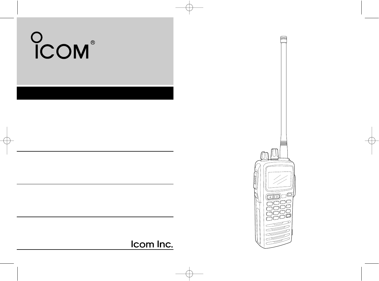
iA6
iA24
VHF AIR BAND TRANSCEIVER
This device complies with Part 15 of the FCC
Rules. Operation is subject to the condition
that this device does not cause harmful inter-
ference.
IC-A24-Nocl.qxd 04.9.1 5:50 PM Page i
i
SAFETY TRAINING INFORMATION
Your Icom radio generates RF electromagnetic energy during
transmit mode. This radio is designed for and classified as
“Occupational Use Only”, meaning it must be used only dur-
ing the course of employment by individuals aware of the haz-
ards, and the ways to minimize such hazards. This radio is
NOT intended for use by the “General Population” in an un-
controlled environment.
This radio has been evaluated for compliance at the distance of 2.5 cm with
the FCC RF exposure limits for “Occupational Use Only”. In addition, your Icom
radio complies with the following Standards and Guidelines with regard to RF
energy and electromagnetic energy levels and evaluation of such levels for ex-
posure to humans:
• FCC OET Bulletin 65 Edition 97-01 Supplement C, Evaluating Compliance
with FCC Guidelines for Human Exposure to Radio Frequency Electro-
magnetic Fields.
• American National Standards Institute (C95.1-1992), IEEE Standard for
Safety Levels with Respect to Human Exposure to Radio Frequency Elec-
tromagnetic Fields, 3 kHz to 300 GHz.
• American National Standards Institute (C95.3-1992), IEEE Recommended
Practice for the Measurement of Potentially Hazardous Electromagnetic
Fields– RF and Microwave.
• The following accessories are authorized for use with this product. Use of
accessories other than those specified may result in RF exposure levels
exceeding the FCC requirements for wireless RF exposure.; Belt Clip (MB-
86/103), Rechargeable Ni-MH Battery Pack (BP-210N) and Alkaline Bat-
tery Case (BP-208N).
To ensure that your expose to RF electromagnetic en-
ergy is within the FCC allowable limits for occupational
use, always adhere to the following guidelines:
WARNING
• DO NOT operate the radio without a proper antenna attached, as this may
damaged the radio and may also cause you to exceed FCC RF exposure
limits. A proper antenna is the antenna supplied with this radio by the man-
ufacturer or antenna specifically authorized by the manufacturer for use
with this radio.
• DO NOT transmit for more than 50% of total radio use time (“50% duty
cycle”). Transmitting more than 50% of the time can cause FCC RF expo-
sure compliance requirements to be exceeded. The radio is transmitting
when “ ” appears on the function display. You can cause the radio to
transmit by pressing the “PTT” switch.
• ALWAYS keep the antenna at least 2.5 cm (1 inch) away from the body
when transmitting and only use the Icom belt-clips which are listed on
page 31 when attaching the radio to your belt, etc., to ensure FCC RF ex-
posure compliance requirements are not exceeded. To provide the recipi-
ents of your transmission the best sound quality, hold the antenna at least
5 cm (2 inches) from your mouth, and slightly off to one side.
The information listed above provides the user with the information needed to
make him or her aware of RF exposure, and what to do to assure that this radio
operates with the FCC RF exposure limits of this radio.
Electromagnetic Interference/Compatibility
During transmissions, your Icom radio generates RF energy that can possibly
cause interference with other devices or systems. To avoid such interference,
turn off the radio in areas where signs are posted to do so. DO NOT operate
the transmitter in areas that are sensitive to electromagnetic radiation such as
hospitals and blasting sites.
Occupational/Controlled Use
The radio transmitter is used in situations in which persons are exposed as
consequence of their employment provided those persons are fully aware of
the potential for exposure and can exercise control over their exposure.
CAUTION
IC-A24-Nocl.qxd 04.9.1 5:50 PM Page ii
ii
FOREWORD
Thank you for purchasing this Icom product. The IC-A24/A6
VHF AIR BAND TRANSCEIVER is designed and built with
Icom’s state of the art technology and craftsmanship. With
proper care this product should provide you with years of
trouble-free operation.
IMPORTANT
READ ALL INSTRUCTIONS carefully and completely
before using the transceiver.
SAVE THIS INSTRUCTION MANUAL—This in-
struction manual contains important operating instructions for
the IC-A24/A6.
EXPLICIT DEFINITIONS
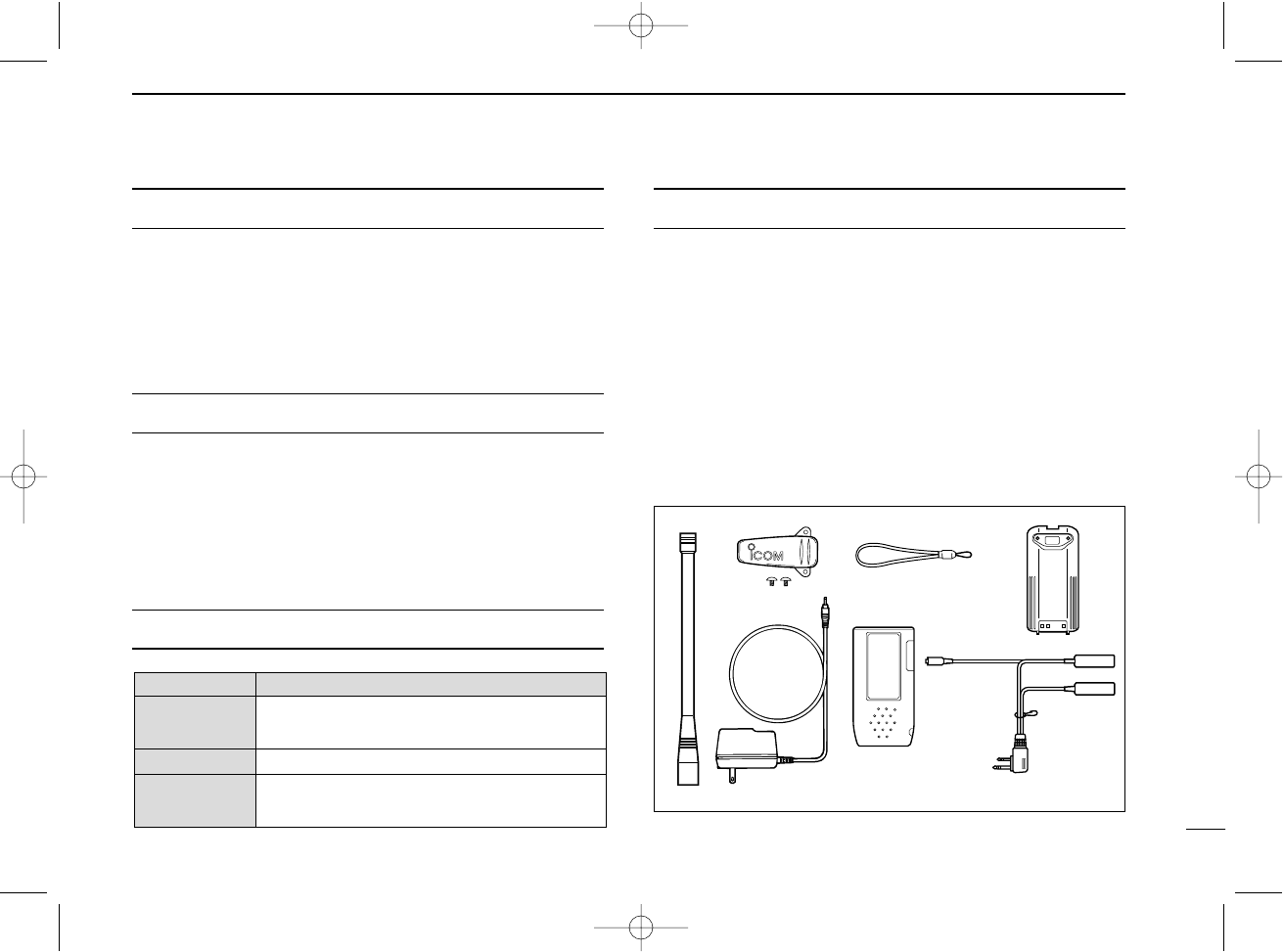
SUPPLIED ACCESSORIES
Accessories included with the transceiver: Qty.
qAntenna .......................................................................... 1
wBelt clip ........................................................................... 1
eHandstrap ....................................................................... 1
rBattery pack* or battery case .......................................... 1
tWall charger* .................................................................. 1
yCarrying case* ................................................................ 1
uHeadset adapter* ........................................................... 1
*The battery pack, wall charger, headset adapter or carrying case
may differ depending on version. Some versions do not include a
battery pack, wall charger, headset adapter or carrying case.
WORD DEFINITION
RWARNING
CAUTION
NOTE
Personal injury, fire hazard or electric shock
may occur.
If disregarded, inconvenience only. No risk
of personal injury, fire or electric shock.
Equipment damage may occur.
qw e
t
r
y
u
IC-A24-Nocl.qxd 04.9.1 5:50 PM Page iii

iii
PRECAUTIONS
RWARNING! NEVER hold the transceiver so that the
antenna is very close to, or touching exposed parts of the
body, especially the face or eyes, while transmitting. The
transceiver will perform best if the microphone is 5 to 10 cm
away from the lips and the transceiver is vertical.
RWARNING! NEVER operate the transceiver with a
headset or other audio accessories at high volume levels.
Hearing experts advise against continuous high volume op-
eration. If you experience a ringing in your ears, reduce the
volume level or discontinue use.
NEVER connect the transceiver to an AC outlet or to a
power source of more than 12 V DC. Such a connection will
damage the transceiver.
NEVER connect the transceiver to a power source that is
DC fused at more than 5 A. Accidental reverse connection will
be protected by this fuse, higher fuse values will not give any
protection against such accidents and the transceiver will be
ruined.
NEVER short the terminals of the battery pack. Also, cur-
rent may flow into nearby metal objects, such as a necklace,
etc. Therefore, be careful when carrying with, or placing near
metal objects, carrying in handbags, etc.
DO NOT allow children to play with any radio equipment
containing a transmitter.
DO NOT operate the transceiver near unshielded electrical
blasting caps or in an explosive atmosphere.
AVOID using or placing the transceiver in direct sunlight or
in areas with temperatures below –10°C (+14°F) or above
+60°C (+140°F).
The use of non-Icom battery packs/chargers may impair
transceiver performance and invalidate the warranty.
Even when the transceiver power is OFF, a slight current still
flows in the circuits. Remove the battery pack or case from
the transceiver when not using it for a long time. Otherwise,
the battery pack or installed dry cell batteries will become ex-
hausted.
Icom, Icom Inc. and the logo are registered trademarks of Icom Incor-
porated (Japan) in the United States, the United Kingdom, Germany, France,
Spain, Russia and/or other countries.
FCC caution: Changes or modifications to this transceiver, not
expressly approved by Icom Inc., could void your authority to
operate this transceiver under FCC regulations. (U.S.A. only)
IC-A24-Nocl.qxd 04.9.1 5:50 PM Page iv

iv
SAFETY TRAINING INFORMATION ............................................... i
FOREWORD ................................................................................... ii
IMPORTANT .................................................................................... ii
EXPLICIT DEFINITIONS ................................................................. ii
SUPPLIED ACCESSORIES ............................................................ ii
PRECAUTIONS............................................................................... iii
TABLE OF CONTENTS ................................................................. iv
1 PANEL DESCRIPTION ........................................................ 1 – 6
■Panel description ................................................................... 1
■Function display ..................................................................... 5
2 ACCESSORY ATTACHMENT .................................................. 7
3 BASIC OPERATION .......................................................... 8 – 11
■Setting a frequency ................................................................ 8
■Setting a squelch level ........................................................... 8
■Selecting a weather channel................................................... 8
■Receiving ............................................................................... 9
■Transmitting ........................................................................... 9
■ANL function ........................................................................... 9
■Low battery indicator ............................................................ 10
■Recall function ..................................................................... 10
■Setting weather alert function................................................ 11
■Accessing 121.5 MHz emergency frequency ....................... 11
■Lock function ........................................................................ 11
■Side tone function ................................................................ 11
■Setting beep tone ................................................................. 11
■Backlighting .......................................................................... 11
4 MEMORY OPERATION ................................................... 12 – 15
■Memory channel selection ................................................... 12
■Transferring memory contents ............................................. 12
■Programming a memory channel ......................................... 13
■Memory names .................................................................... 14
■Clearing the memory contents ............................................. 14
5 SCAN OPERATION ......................................................... 16 – 17
■Scan types ........................................................................... 16
■COM band scan ................................................................... 16
■Memory scan ....................................................................... 16
■Weather channel scan (U.S.A. version only) ............................ 17
■“TAG” channels ................................................................... 17
6 VOR NAVIGATION (IC-A24 only) .................................... 18 – 24
■VOR indications ................................................................... 18
■VOR functions ...................................................................... 19
■Flying to a VOR station ........................................................ 20
■Entering a desired course .................................................... 22
■Crosschecking position ........................................................ 22
■Duplex operation (U.S.A. version only) .................................... 24
7 BATTERY PACKS ........................................................... 25 – 27
■Battery charging ................................................................... 25
■Battery cautions ................................................................... 25
■Optional battery case ........................................................... 26
■Optional battery chargers ..................................................... 27
8 CLONING ................................................................................ 28
9 TROUBLESHOOTING ............................................................ 29
10 SPECIFICATIONS .................................................................. 30
11 OPTIONS ................................................................................ 31
12 QUICK REFERENCE ...................................................... 32 – 33
13 OPTIONAL HEADSET CONNECTION .................................. 34
TABLE OF CONTENTS
IC-A24-Nocl.qxd 04.9.1 5:50 PM Page v
1
1PANEL DESCRIPTION
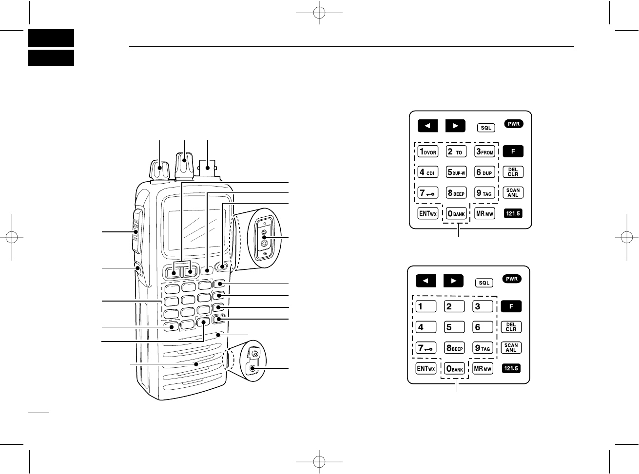
■Panel description
ert
u
y
i
o
Microphone
Speaker
!6
!5
!7
q
w
!1
!0
!2
!3
!4
!7
IC-A24
!7
IC-A6
IC-A24-Nocl.qxd 04.9.1 7:02 PM Page 2
2
1
2
3
4
5
6
7
8
9
10
11
12
13
14
15
16
qBACKLIGHT SWITCH [LIGHT] (p. 11)
Turns the backlight for display and keypad ON or OFF.
wPTT SWITCH [PTT] (p. 9)
Push and hold to transmit; release to receive.
•“ ” appears on the function display while transmitting.
eVOLUME [VOL] (p. 9)
Adjusts the audio level.
rTUNING DIAL [DIAL] (pgs. 8–12)
➥Rotate [DIAL] to select the desired frequency, WX chan-
nel number, BANK number and memory channel.
➥Rotate [DIAL] to set the squelch level and beep tone
level.
tANTENNA CONNECTOR [ANT] (p. 7)
Connects the supplied antenna.
yRECALL CHANNEL UP/DOWN KEYS [ΩΩ]/[≈≈] (p. 10)
➥Push to enter the recall function mode.
➥Push to call the stored frequency in the recall
mode.
➥Push , then push [Ω]/[≈]to replace stored re-
call frequencies to back or front.
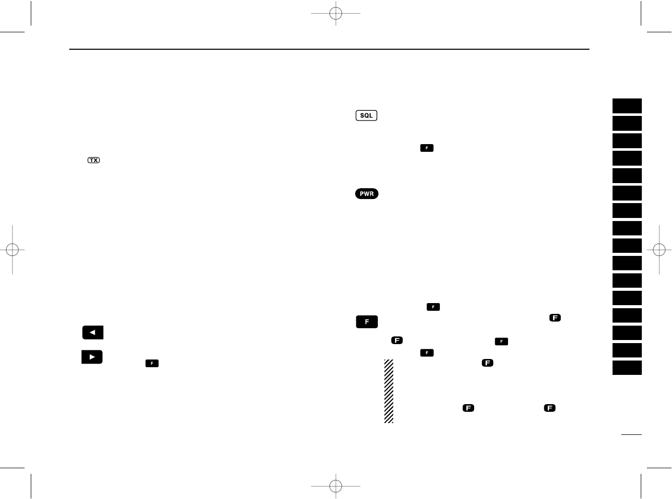
uSQUELCH KEY [SQL•WX-ALERT] (p. 8)
➥Push [SQL•WX-ALERT], then rotate [DIAL] to se-
lect the squelch level.
• 24 squelch levels and squelch open (0) are available.
➥Push , then push [SQL•WX-ALERT] to turn
the WX-alert function ON or OFF.
iPOWER SWITCH [PWR] (pgs. 9, 28)
➥Push and hold for 2 sec. to turn the power ON
or OFF.
➥While pushing and holding [MR•MW], push
[PWR] to enter the cloning function mode.
oEXTERNAL SPEAKER AND MICROPHONE JACKS
[MIC/SP] (p. 34)
Connects an OPC-499 HEADSET ADAPTER and headset, if
desired.
!0 FUNCTION KEY
Push to call up the function indicator, “”, then
push another key to access its secondary function.
•“ ” appears for 3 sec. after is pushed; at this time
pushing again cancels the indication.
NOTE: In general, “” disappears when an-
other key is pushed to activate a secondary
function. However, some keys which have more
than one secondary function, (such as [DUP]),
do not cancel “”. In this case, “” disap-
pears automatically after 3 sec.
1
PANEL DESCRIPTION
IC-A24-Nocl.qxd 04.9.1 5:50 PM Page 3
3
1PANEL DESCRIPTION
!1 CLEAR KEY [CLR•DEL] (pgs. 8–17)
➥Push to turn to the frequency mode, when WX
channel, 121.5 MHz, squelch level setting or
beep tone setting is selected.
➥Push , then push [CLR•DEL] to delete a re-
call frequency data.
➥Push to clear the entered comment of memory
name while programming.
➥Push to stop the scan function to turn to the fre-
quency mode while the scan function is operat-
ing.
!2 ANL KEY [ANL•SCAN] (pgs. 9, 16, 17)
➥Push to turn the ANL function ON or OFF.
➥Push , then push [ANL•SCAN] to start the
scan function.
!3 EMERGENCY KEY [121.5 MHz] (p. 11)
Push for 2 sec. to select the 121.5 MHz emergency
frequency.
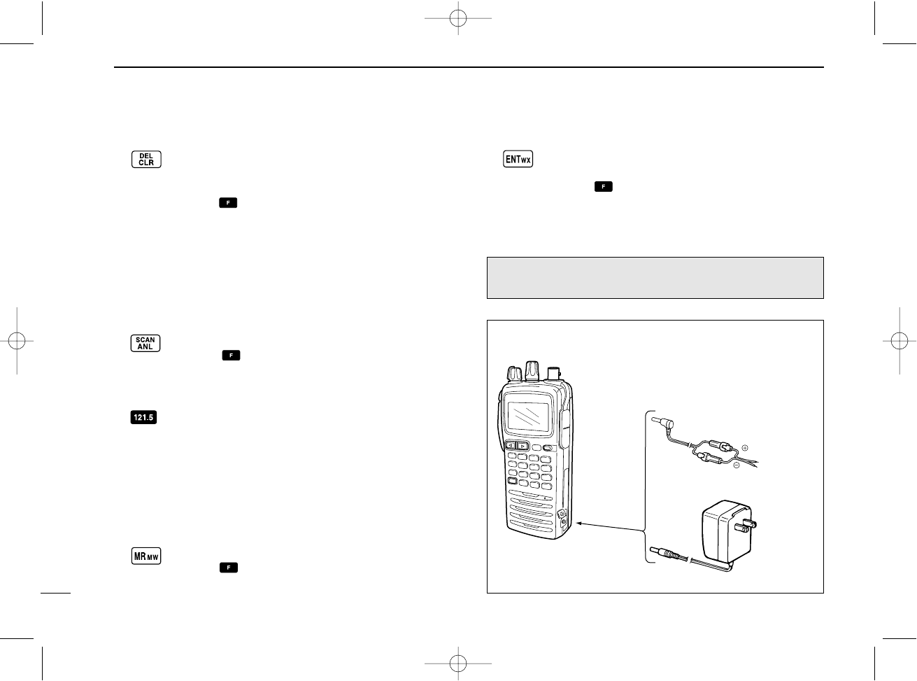
!4 DC POWER JACK
Connect the AC adapter or optional cable to charge the
battery pack or to operate by external power supply. (see
right illustration)
!5 MEMORY MODE KEY [MR•MW] (pgs. 12–15)
➥Push to call the memory channel mode.
➥Push , then push [MR•MW] to program the
contents into the memory channels.
!6 ENTER KEY [ENT•WX] (pgs. 8, 14)
➥Push to enter the numeral input. Enters con-
secutive zero digits. (p. 8)
➥Push , then push [ENT•WX] to enter the
weather channel selection mode (U.S.A. version
only). (p. 8)
➥Push to program the memory name. (p. 14)
NOTE: Some functions may not be available depending on
versions. Ask your dealer for details.
Wall charger
OPC-254L
(optional)
To
[DC POWER
JACK]
white
black
IC-A24/A6
To a 11 V DC
power source
• DC POWER CONNECTION
IC-A24-Nocl.qxd 04.9.1 5:50 PM Page 4
4
1
PANEL DESCRIPTION
1
2
3
4
5
6
7
8
9
10
11
12
13
14
15
16
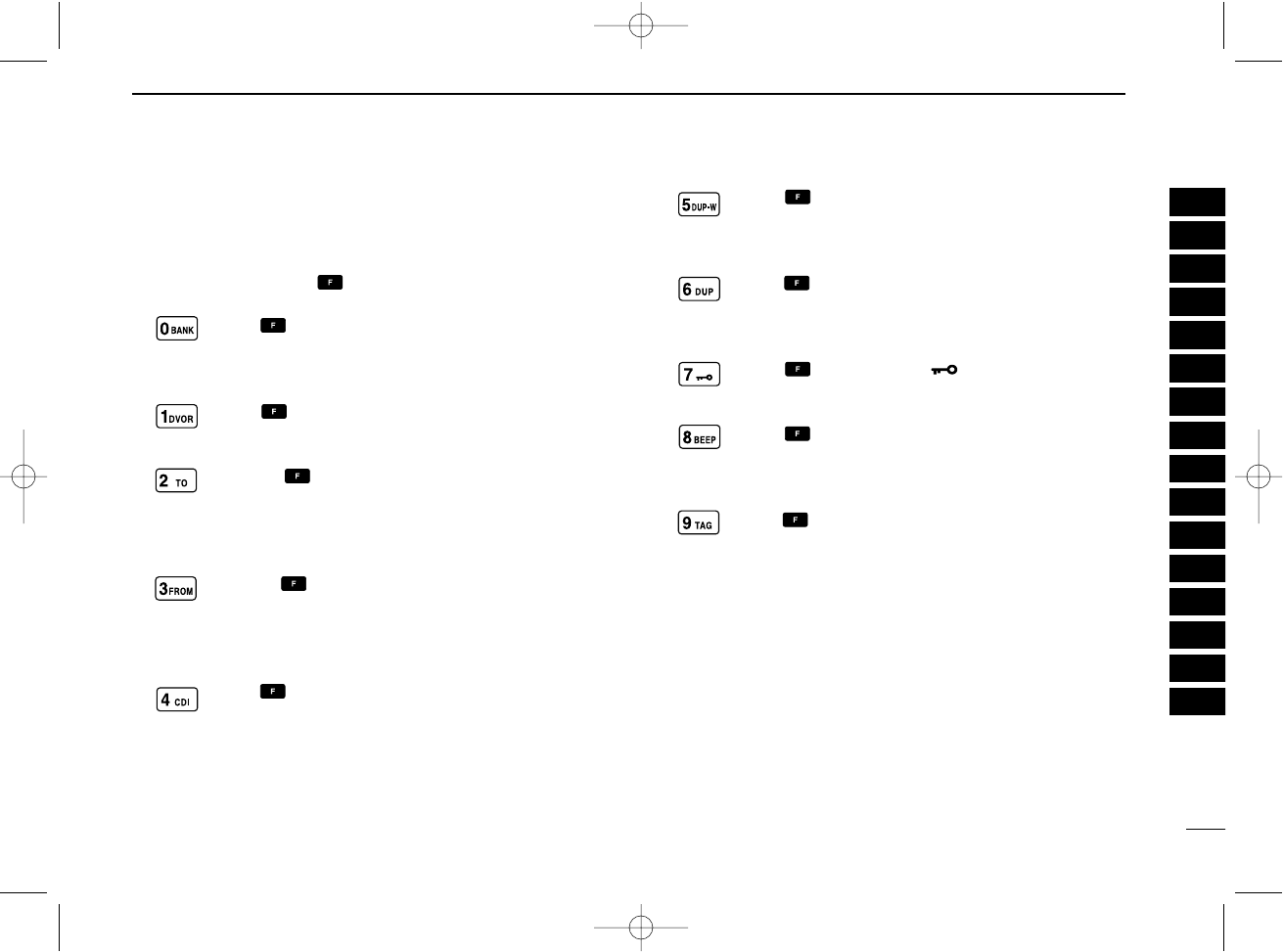
!7 DIGIT KEYS
➥Input the specified digit during frequency input, memory
channel selection, etc.
➥In addition, each key has one or more secondary func-
tion after pushing as follows:
Push , then push [0•BANK] to select the mem-
ory BANK number to rotate [DIAL] on the memory
operation. (p. 12)
Push , then push [1•DVOR] to select the DVOR
display from the CDI display in NAV band. (p. 19)*1
➥Push , then push [2•TO] to change the
course indicator characteristics to “TO” flag in
the DVOR display in NAV band. (p. 19)*1
➥Corrects the deviation while using “TO” flag. *1
➥Push , then push [3•FROM] to change the
course indicator characteristics to “FROM” flag
in the DVOR display in NAV band. (p. 19)*1
➥Corrects the deviation while using “FROM” flag. *1
Push , then push [4•CDI] to select the CDI dis-
play from the CDI display in NAV band. (p. 19)*1
Push , then push [5•DUP-W] to set the duplex
frequency in NAV band for U.S.A. version only.
(p. 24)*1
Push , then push [6•DUP] to turn the duplex
function ON and OFF in NAV band for U.S.A. ver-
sion only. (p. 24)*1
Push , then push [7•] to turn the key lock
function ON and OFF. (p. 11)
Push , then push [8•BEEP] to turn the beep
tone setting mode ON (p. 11).
•Adjustable level; 0 to 9
Push , then push [9•TAG] to set the displayed
memory or weather channel as a “TAG” channel.
(p. 17)
*1These functions available on the IC-A24 only.
IC-A24-Nocl.qxd 04.9.1 5:50 PM Page 5
5
1PANEL DESCRIPTION
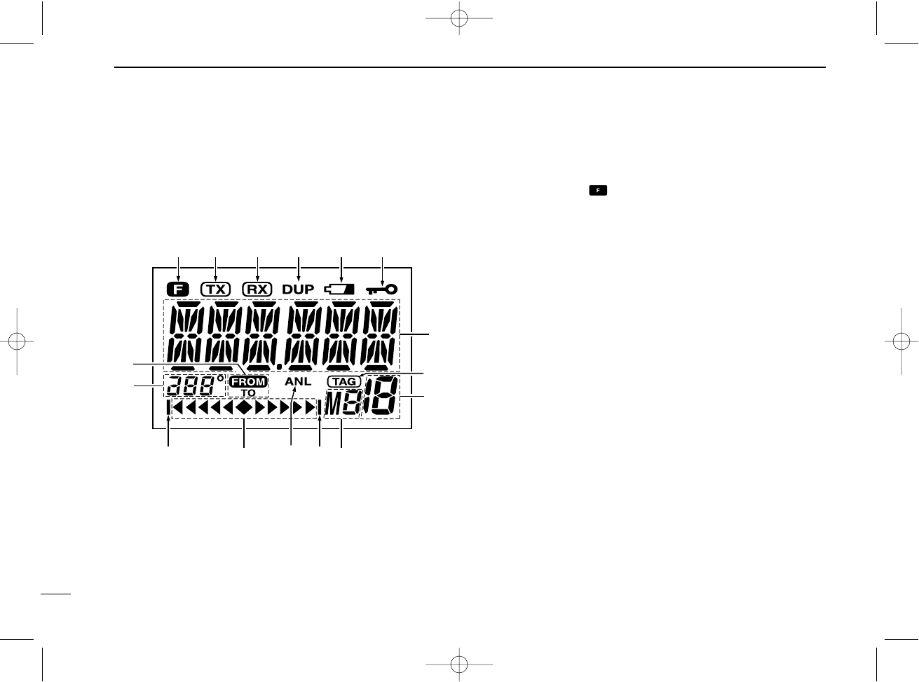
■Function display
qFUNCTION INDICATOR (p. 2)
Appears when is pushed.
wTX INDICATOR (p. 9)
Appears while transmitting.
eRX INDICATOR (p. 9)
Appears when receiving a signal or when the squelch
opens.
rDUPLEX INDICATOR (IC-A24 only) (p. 24)
➥“DUP” appears when the duplex function is activated in
NAV mode.
➥“DUP” blinks while setting the duplex frequency.
tLOW BATTERY INDICATOR (p. 10)
➥Appears when the battery is nearing exhaustion. The at-
tached battery pack requires recharging.
➥Appears and flashes when battery replacement is nec-
essary.
yLOCK INDICATOR (p. 11)
Appears while the lock function is in use.
uFREQUENCY DISPLAY (pgs. 8, 14)
➥Shows the operating frequency.
➥Shows the channel name when the memory name func-
tion is selected.
i
qw e r t y
o
!0
!1!1 !2!3
!4
u
!5
IC-A24-Nocl.qxd 04.9.1 5:50 PM Page 6

6
1
PANEL DESCRIPTION
1
2
3
4
5
6
7
8
9
10
11
12
13
14
15
16
iTAG CHANNEL INDICATOR (p. 17)
“” appears when the memory channel is set as a TAG
channel.
oMEMORY CHANNEL INDICATOR (pgs. 12–15)
Shows the memory channel number.
!0 MEMORY BANK NUMBER INDICATOR (p. 12)
Shows the selected memory bank number.
!1 OVERFLOW INDICATOR (IC-A24 only) (pgs. 18–22)
Appears when the deviation between the desired course
and flying course is over 10 degrees.
!2 ANL INDICATOR (p. 9)
Appears while the ANL (Automatic Noise Limiter) function
is in use.
!3 COURSE DEVIATION NEEDLES (IC-A24 only)
(pgs. 18–22)
Indicates the deviation between the desired course and
your actual flying course every 2 degrees.
!4 COURSE INDICATORS (IC-A24 only) (p. 19)
➥Indicates where your aircraft is located on a VOR radial
in DVOR mode.
➥Indicates where your desired course is located on a
VOR radial in CDI mode.
!5 TO-FROM INDICATOR (IC-A24 only) (p. 19)
Indicates whether the VOR navigation information is
based on a course leading to the VOR station or leading
away from the VOR station.
IC-A24-Nocl.qxd 04.9.1 5:50 PM Page 7
7
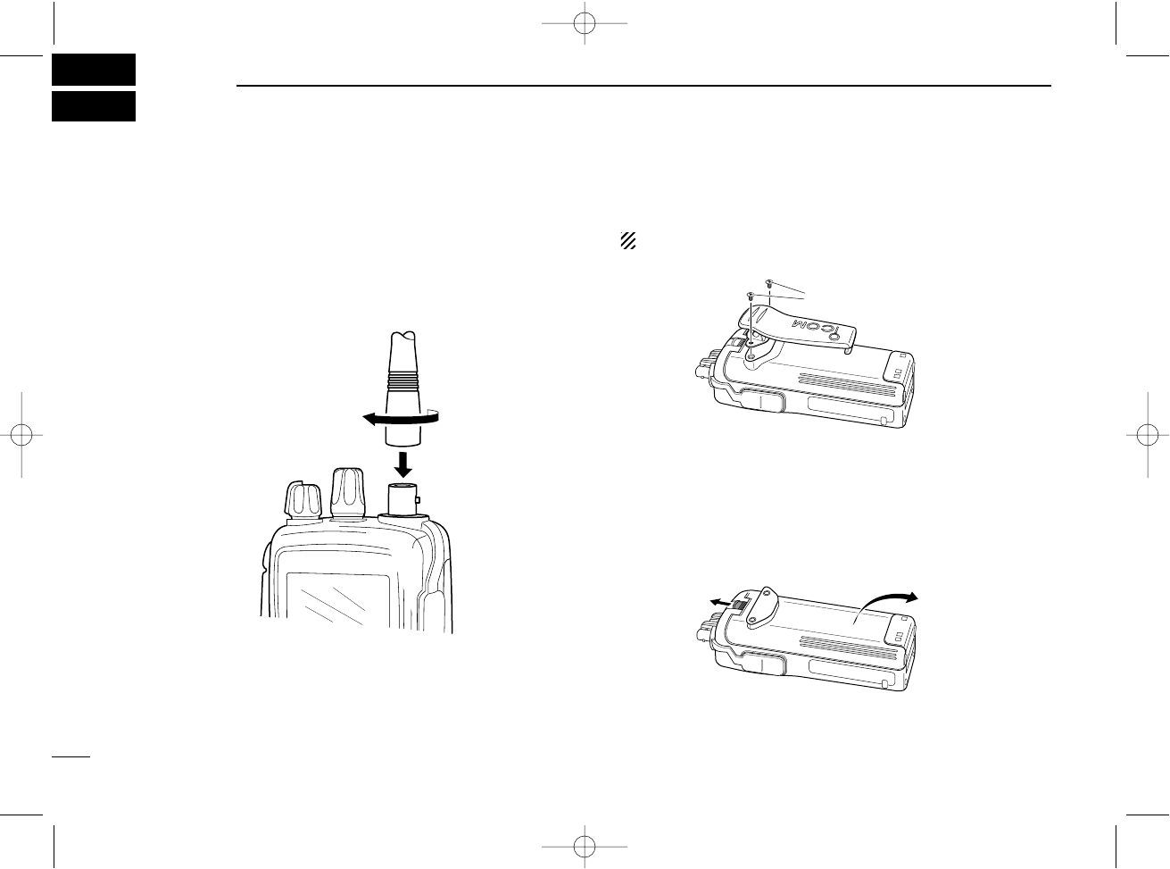
DAntenna
CAUTION: DO NOT transmit without an antenna. Other-
wise the transceiver may be damaged.
Insert the supplied antenna into the antenna connector and
screw down the antenna as shown below.
DBelt clip
Conveniently attaches to your belt.
Attach the belt clip with the supplied screws as below.
NOTE: Use the supplied screws only.
DBattery pack replacement
Before replacing the battery pack, push [PWR] for 2 sec. to
turn the power OFF.
Slide the battery release button forward, then pull the battery
pack upward with the transceiver facing away from you.
Supplied screws
2ACCESSORY ATTACHMENT
IC-A24-Nocl.qxd 04.9.1 5:50 PM Page 8
8
3
BASIC OPERATION
■Setting a frequency
ïUsing keypad
qPush [PWR] for 2 sec. to turn power ON, then push
[CLR•DEL] to select the frequency mode when memory CH
number or WX CH number appears on the function dis-
play.
wPush 5 appropriate digit keys to input the frequency.
•Push [1]* as the 1st digit.
• When a wrong digit is input, push [CLR•DEL] to clear,
then repeat step wagain.
•Push [ENT•WX] to enter consecutive zero digits.
•Only [2]*, [5]*, [7•] and [0•BANK] can be entered as the
5th and final digit.
[EXAMPLE]
• 111.225 MHz: Push
• 117.250 MHz: Push
• 120.000 MHz: Push
• 125.300 MHz: Push
ïUsing the tuning dial
qPush [PWR] for 2 sec. to turn power ON, then push
[CLR•DEL] to select the frequency mode when memory CH
number or WX CH number appears on the function dis-
play.
wRotate [DIAL] to set the desired frequency.
• To select the 1 MHz tuning step, push , then rotate
[DIAL]. Push again to return the normal tuning.
■Setting a squelch level
The transceiver has a noise squelch circuit to mute undesired
noise while receiving no signal.
qPush [SQL•WX-ALERT], then rotate [DIAL] to select the
squelch level.
• ‘SQL--0’is loose squelch and ‘SQL--24’is tight squelch.
•Appears “” while the squelch is open.
wPush [SQL•WX-ALERT] or [CLR•DEL] to exit the squelch
set mode.
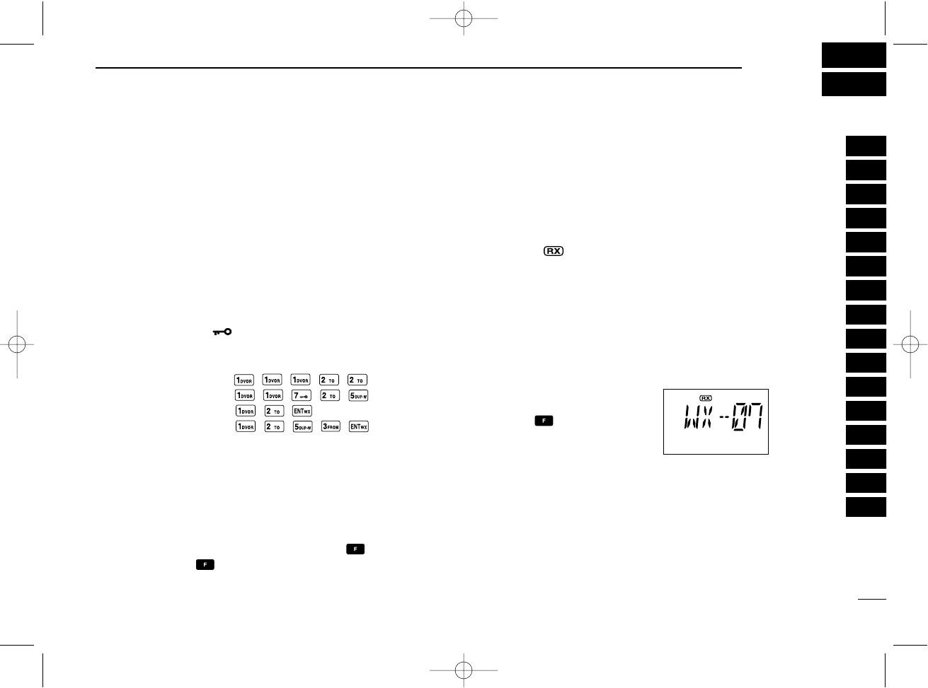
■Selecting a weather channel
(U.S.A. version only)
The U.S.A. version has VHF marine WX (weather) channel
receiving capability for flight
planning.
qPush ,then push
[ENT•WX] to select WX
channel mode.
•“WX--” and previously se-
lected channel number appears.
wRotate [DIAL] to select the desired WX channel.
ePush [CLR•DEL] to exit the WX channel mode and return
to frequency mode.
1
2
3
4
5
6
7
8
9
10
11
12
13
14
15
16
IC-A24-Nocl.qxd 04.9.1 5:50 PM Page 9
9
3BASIC OPERATION
■Receiving
qPush [PWR] to turn the power ON.
wPush [SQL•WX-ALERT], then rotate [DIAL] counterclock-
wise to select the squelch level 0.
eRotate [VOL] to adjust the audio level.
rPush [SQL•WX-ALERT], then rotate [DIAL] clockwise until
the noise is muted.
•“ ” indicator disappears.
tSet the desired frequency using [DIAL] or keypad.
yPush [ANL•SCAN] to reduce pulse noise such as that
caused by engine ignition systems, if necessary.
•“ ” appears on the display.
uWhen a signal is received on the set frequency:
•“ ” indicator appears.
• Squelch opens and audio is emitted from the speaker.
When [SQL] control is too “deep,” squelch may not open for
weak signals. To receive weak signals, set the squelch to a
“loose.”
■Transmitting
qSet the desired frequency in COM band using [DIAL] or
keypad.
•COM band frequency range: 118.00–136.975 MHz
wPush and hold [PTT] to transmit.
•“ ” indicator appears.
eSpeak into the microphone at a normal voice level.
•DO NOT hold the transceiver too close to your mouth or speak
too loudly. This may distort the signal.
rRelease [PTT] to return to receive.
■ANL function
The ANL (Automatic Noise Limiter) function reduces noise
components while receiving.
• Push [ANL•SCAN] to turn the ANL function ON/OFF.
“” appears on the display while the ANL function is ON.
CAUTION: Transmitting without an antenna may damage
the transceiver.
NOTE: To prevent interference, listen on the frequency be-
fore transmitting. If the frequency is busy, wait until the
channel is clear.
IC-A24-Nocl.qxd 04.9.1 5:50 PM Page 10
10
3
BASIC OPERATION
■Low battery indicator
Low battery indicator appears
when the battery power has de-
creased to a specified level. The
attached battery pack requires
recharging.
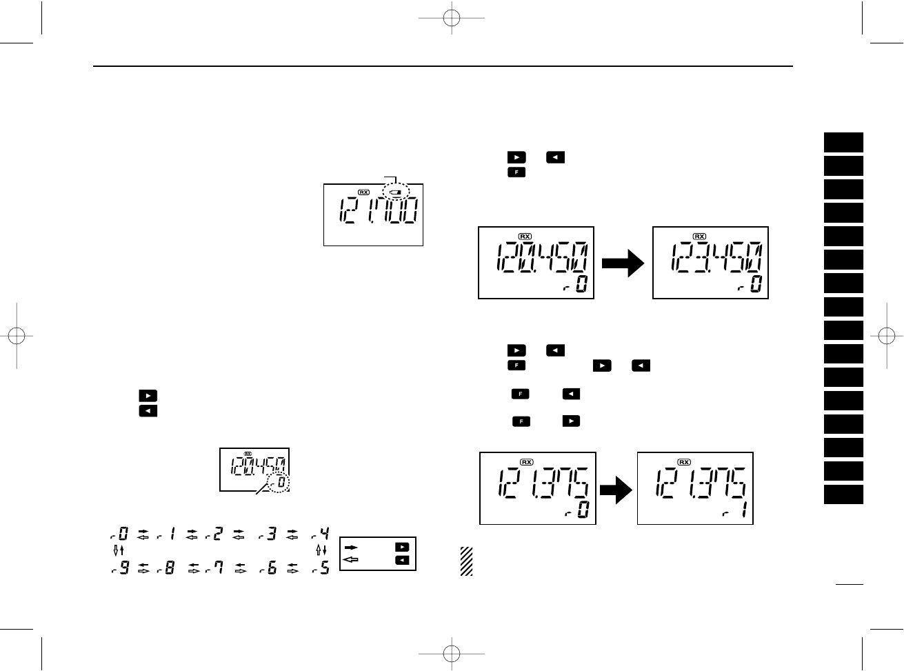
■Recall function
The recall function stores the 10 of recently used frequencies.
The function stores frequencies when operating some func-
tion at the transceiver (except memory, weather and emer-
gency channels).
DCalling the stored frequencies
➥Push , then call the stored 1st used frequency.
➥Push , then call the stored 10th used frequency.
DDeletes the stored recall channel
qPush or to select the deleting recall channel.
wPush , then push [CLR•DEL] for 2 sec. to delete it.
• (e.g.) Deletes “r0” recall channel which is stored 120.450 MHz,
and “r1” recall channel stores 123.450 MHz.
DReplaces the stored recall channel
qPush or to select the replacing recall channel.
wPush , then push or to replace it.
• Replaces the selected channel into the previous channel when
push , then .
• Replaces the selected channel into the behind channel when
push , then .
• (e.g.) Replaces “r0” which is stored 121.375 MHz into “r1”.
NOTE: Deletes in order of old
recall
channel automatically
when stored frequencies exceeds 10 channels.
Low battery indicator
Appears recall number.
: Push
: Push
• Recall number rotation
1
2
3
4
5
6
7
8
9
10
11
12
13
14
15
16
IC-A24-Nocl.qxd 04.9.1 7:03 PM Page 11
11
3BASIC OPERATION
■
Setting weather alert function
An NOAA broadcast station transmits a weather alert tone be-
fore any important weather announcements. When the
weather alert function is turned ON, the transceiver detects
the alert, and sounds a beep tone until the transceiver is op-
erated. The previously selected (used) weather channel is
checked any time during standby, or while scanning.
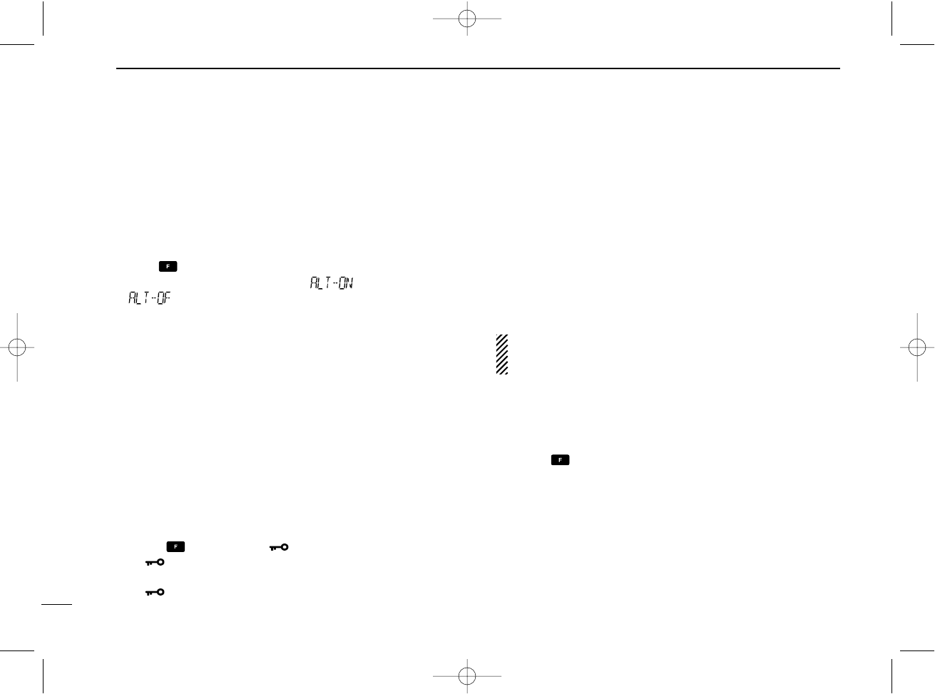
•Push , then push [SQL•WX-ALERT] to turns the weather
alert function ON (Indicates “”)/OFF (Indicates
“”).
■Accessing 121.5 MHz
emergency frequency
The IC-A24 and IC-A6 can quickly access to the 121.5 MHz
emergency frequency. This function can be activated even
when the key lock function is in use.
qPush [121.5] for 2 sec. to call the emergency frequency.
wPush [CLR•DEL] to exit from the emergency frequency.
■Lock function
The lock function prevents accidental frequency changes and
accidental function activation.
qPush , then push [7•] to turn the lock function ON.
•“ ” appears.
wTo turn the function OFF, repeat step qabove.
•“ ” disappears.
■Side tone function
When using an optional headset, the transceiver outputs your
transmitted voice to the headset for monitoring. Connect the
optional headset with the transceiver when using this function
(OPC-499 HEADSET ADAPTER and headset are required).
(p. 34)
DSetting the side tone level
qPush [PTT] to turn the transmit mode ON.
wDuring transmit mode, rotate [DIAL] to adjust the monitor-
ing level.
• ‘ST--0’is OFF and ‘ST--10’is Max. level.
NEVER operate the transceiver with a headset at high vol-
ume levels for long period. A ringing in your ears may
occur. If so, reduce the monitor level or discontinue use.
■Setting beep tone
The beep tone which sounds at the push of a switch can be
set, if desired.
qPush , then push [8•BEEP] to enter the beep tone
setting mode.
wRotate [DIAL] to set the beep level.
• ‘BEP-- 0’is OFF and ‘BEP-- 9’is Max. level.
ePush [CLR•DEL] to exit the beep tone set mode.
■Backlighting
Push [LIGHT] to turn the display and keypad backlighting ON
or OFF.
IC-A24-Nocl.qxd 04.9.1 5:50 PM Page 12
12
4
MEMORY OPERATION
■Memory channel selection
The transceiver has 200 memory channels for storage of
often-used frequencies along with 6-character notes.
qPush [MR•MW] to select memory mode.
•Memory BANK number and memory CH. number appears.
Using [DIAL]:
wPush [0•BANK], then rotate [DIAL] to select the desired
memory BANK number, then push [0•BANK] (or
[CLR•DEL]) to exit the BANK selection mode.
• “BANK” appears.
eRotate [DIAL] to select the desired memory CH. number.
•If no memory CH. is programmed in the selected BANK, no
memory CH. selection is available.
Using the Keypad:
wPush [0•BANK], then push appropriate digit key ([0•BANK]
to [9•TAG]) to select the desired memory BANK number,
then push [0•BANK] (or [CLR•DEL]) to exit the BANK-se-
lection mode.
• “BANK” appears.
ePush 2 appropriate digit key (00 to 19) to select the de-
sired memory CH. number.
•If no memory CH. is programmed in the selected BANK, no
memory CH. selection is available.
NOTE: Comments appear first when programmed, how-
ever, the transceiver can be programmed by your dealer to
show the operating frequency first. Push [MR•MW] to dis-
play the comment in this case.
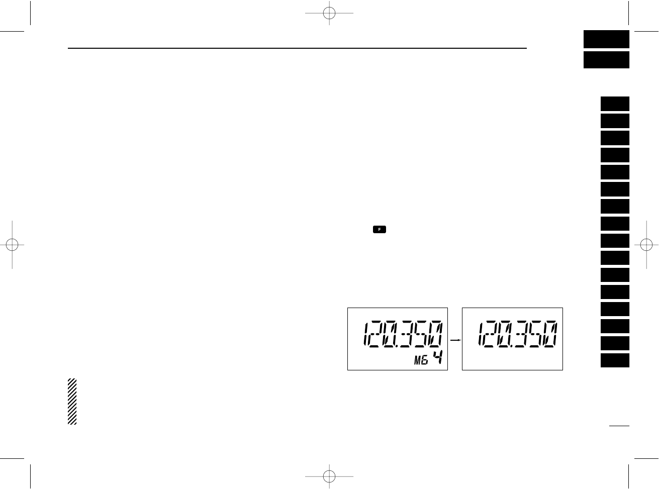
■Transferring memory
contents
This function transfers a memory channel’s contents into the
frequency mode. This is useful when searching for signals
around a memory channel’s frequency.
qPush [MR•MW] to select memory mode.
wSelect the desired memory channel to be transferred using
[DIAL] or keypad.
ePush , then push [MR•MW] to transfer the memory
channel’s contents into the frequency mode.
•BANK number and memory CH. number disappears as
frequency mode is automatically selected and the mem-
ory contents are transferred.
Memory mode Frequency mode
1
2
3
4
5
6
7
8
9
10
11
12
13
14
15
16
IC-A24-Nocl.qxd 04.9.1 5:50 PM Page 13
13
4MEMORY OPERATION
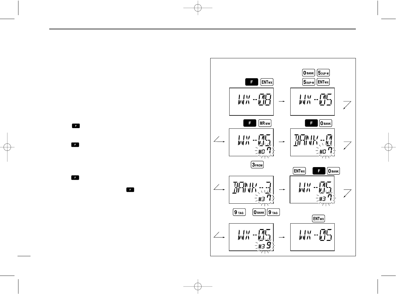
■Programming a memory
channel
The transceiver has 200 (20 CH. ×10 BANK) memory chan-
nels for storage of often-used frequencies.
qPush [CLR•DEL] to select the frequency mode, if neces-
sary.
wSelect the desired frequency.
• Push , then push [ENT•WX] to select a weather channel.*
•Set the desired frequency or weather channel* using [DIAL] or
keypad.
ePush , then push [MR•MW] to program the contents
into the selected memory channel.
•Memory BANK and memory channel number appears.
rRotate [DIAL] to select the desired memory channel num-
ber.
•Push , then push [0•BANK] to select the BANK number if de-
sired.
• Push [CLR•DEL], [ENT•WX] or , then push [0•BANK] to exit
the BANK selection mode.
•“M,” BANK and memory numbers are blinks.
tPush [ENT•WX] to program the information into the chan-
nel and return to the frequency mode.
*Weather channel: U.S.A. version only.
(or rotate [DIAL])
(or rotate [DIAL])
Push
Push
Push
Push
Push
or
or
Push
Push
Push
or
• EXAMPLE: Programming WX-05* into memory BANK 3/
memory channel 9.
IC-A24-Nocl.qxd 04.9.1 5:50 PM Page 14
14
4
MEMORY OPERATION
■Memory names
ïProgramming memory names
The memory channel can display a 6-character names in-
stead of the programmed frequency.
qRotate [DIAL] to select the desired frequency in the fre-
quency mode.
wPush ,then push [MR•MW] to program the contents
into the selected memory channel.
eRotate [DIAL] to select the desired memory channel to be
programmed.
•Push [0•BANK] to select the BANK number if desired. Push
[CLR•DEL] to exit the BANK selection mode.
rPush [MR•MW] to enter the memory name programming
mode.
•“-- -- -- -- -- -- ” appears on the display.
tPush the appropriate digit key several times to select the
desired character as listed at right.
•To erase a character, overwrite with a space (displayed as _).
•To move the cursor forwards or backwards, use [DIAL].
yPush [ENT•WX] to program the name.
•Flashing the memory name stops.
•When no name is programmed, the display shows the operating
frequency.
•To clear the programmed memory names, push [CLR•DEL] be-
fore pushing [ENT•WX].
■
Clearing the memory contents
Unwanted memory channels can be cleared. Programming
over a memory channel also clears the previously pro-
grammed contents. Memory channel 1 cannot be cleared.
qSelect the memory channel to be cleared.
wPush , then push and hold [CLR•DEL] for 1 sec.
•“-- -- -- -- -- --” appears momentarily, then the next selec-
table channel appears.
Key Character Key Character Key Character
1 1, Q, Z 2 2, A, B, C 3 3, D, E, F
4 4, G, H, I 5 5, J, K, L 6 6, M, N, O
7 7, P, R, S 8 8, T, U, V 9 9, W, X, Y
ENT Program 0 0, space, -
1
2
3
4
5
6
7
8
9
10
11
12
13
14
15
16
IC-A24-Nocl.qxd 04.9.1 5:50 PM Page 15
15
4MEMORY OPERATION
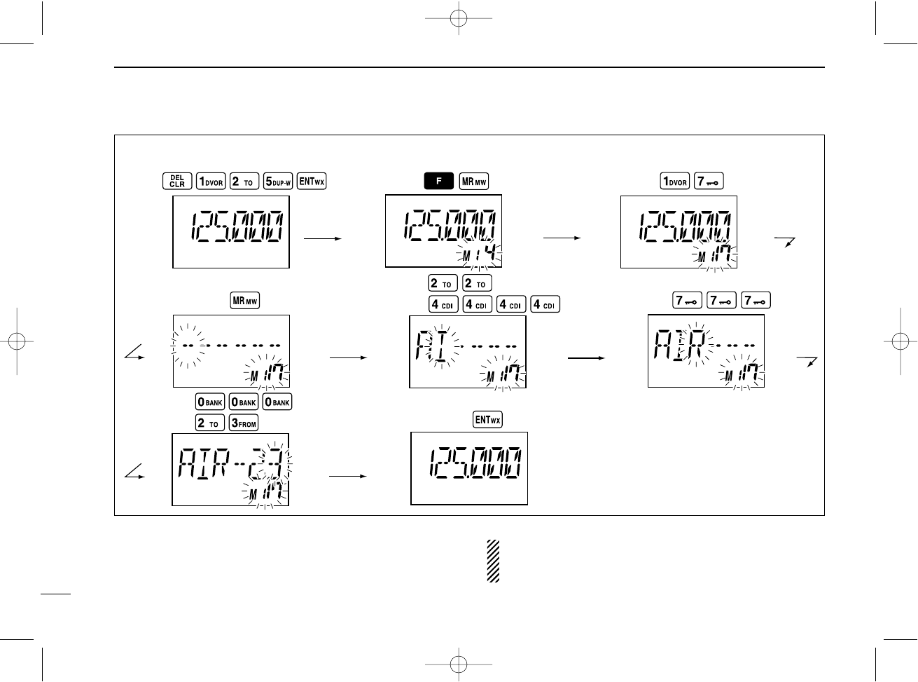
Push
Push
Push PushPush
Push
Push Push
Push Push
• EXAMPLE: Programming 125.000 MHz into memory BANK 1/ memory channel 17 with “AIR-23” as a comment.
NOTE: Push [0•BANK], then rotate [DIAL] to select the
BANK number, if desired. Push [CLR•DEL] to continue
memory name programming.
IC-A24-Nocl.qxd 04.9.1 5:50 PM Page 16
16
5
SCAN OPERATION
■Scan types
The U.S.A. version has 3 scan types to suit your needs. The
non-U.S.A. versions have 2 scan types.
■COM band scan
qPush [CLR•DEL] to select the frequency mode.
wPush [SQL•WX-ALERT] to set the squelch level to the point
where noise is just muted.
ePush , then push [ANL•SCAN] to start the scan.
• When a signal is received, the scan pauses until it disappears.
•To change the scanning direction, rotate [DIAL].
rTo stop the scan, push [CLR•DEL].
■Memory scan
qPush [MR•MW] to select memory mode.
wPush [SQL•WX-ALERT] to set the squelch level to the point
where noise is just muted.
ePush , then push [ANL•SCAN] to start the scan.
• When a signal is received, the scan pauses until it disappears.
•To change the scanning direction, rotate [DIAL].
rTo stop the scan, push [CLR•DEL].
WEATHER CHANNEL SCAN
Repeatedly scans all “TAG” weather channels. Weather
channels are available for the U.S.A. version only.
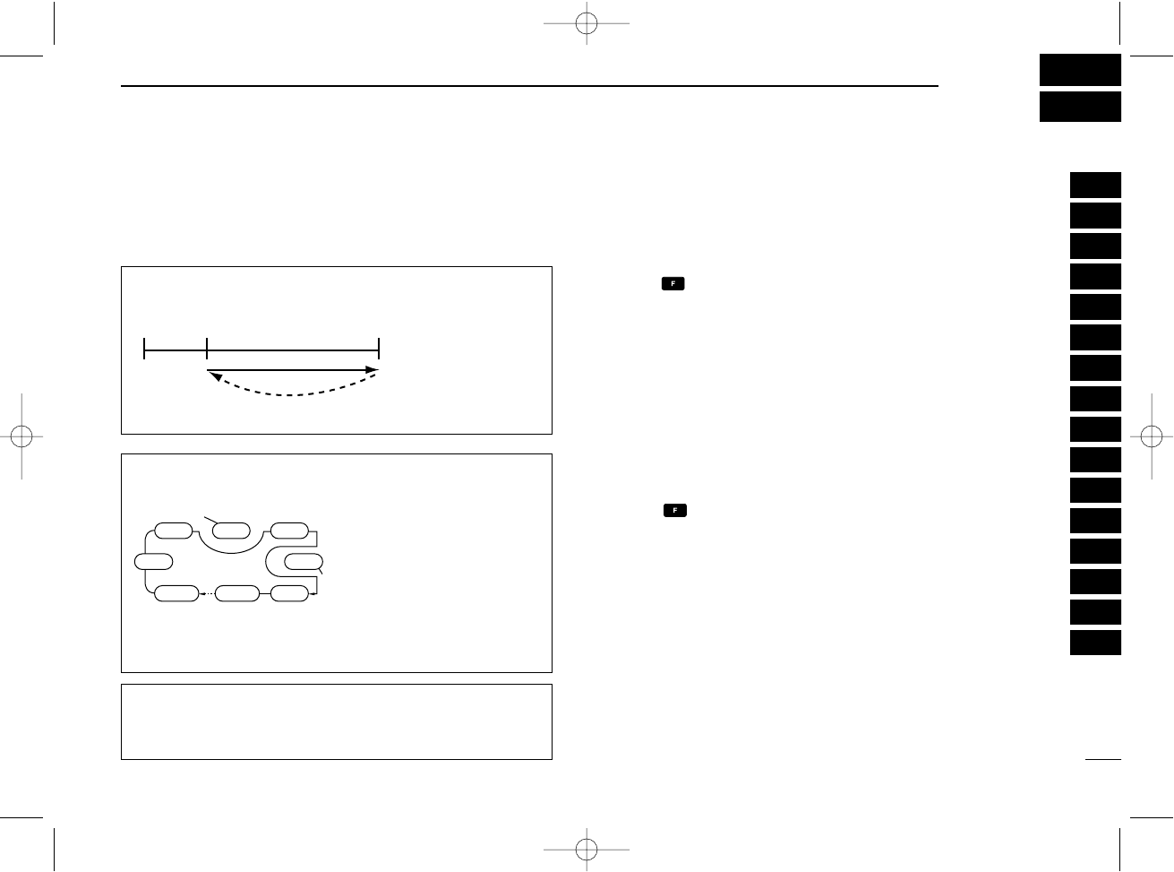
MEMORY SCAN
Repeatedly scans all
“TAG” memory chan-
nels. Used for checking
often-used channels
and bypassing usually
busy channels such as
control-tower frequen-
cies.
COM BAND SCAN
Repeatedly scans
all frequencies
over the entire
COM band.
108.00
MHz
Scan
Jump
118.00
MHz
136.975
MHz
non-TAG
channel
non-TAG channel
Mch 2 Mch 4 Mch 6
Mch 7Mch 1
Mch 8Mch 10Mch 19
1
2
3
4
5
6
7
8
9
10
11
12
13
14
15
16
IC-A24-Nocl.qxd 04.9.1 5:50 PM Page 17
17
5SCAN OPERATION
■Weather channel scan
(U.S.A. version only)
qPush , then push [ENT•WX] to select a weather chan-
nel.
wSet squelch to the point where noise is just muted.
ePush , then push [ANL•SCAN] to start the scan.
• When a signal is received, the scan pauses until it disappears.
•To change the scanning direction, rotate [DIAL].
rTo stop the scan, push [CLR•DEL].
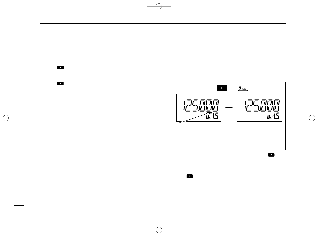
■“TAG” channel setting
Memory and weather channels* can be specified to be
skipped for the memory and weather channel* scans respec-
tively. The “TAG” channel function is only available during
scan operation.
qPush [MR•MW] to select memory mode; or, push , then
push [ENT•WX] to select a weather channel.*
wSelect the desired memory channel to be a “TAG” chan-
nel.
ePush ,then push [9•TAG] to set a “TAG.”
•“TAG” appears.
•Non-“TAG” channels are skipped during scan.
rTo cancel the “TAG” setting, repeat above steps.
*Weather channel: U.S.A. version only.
Memory channel 15 is
scanned during memory
scan.
Memory channel 15 is
skipped during scan.
Push then
Appears the “TAG” indicator.
IC-A24-Nocl.qxd 04.9.1 5:50 PM Page 18
18
6
VOR NAVIGATION (IC-A24 ONLY)
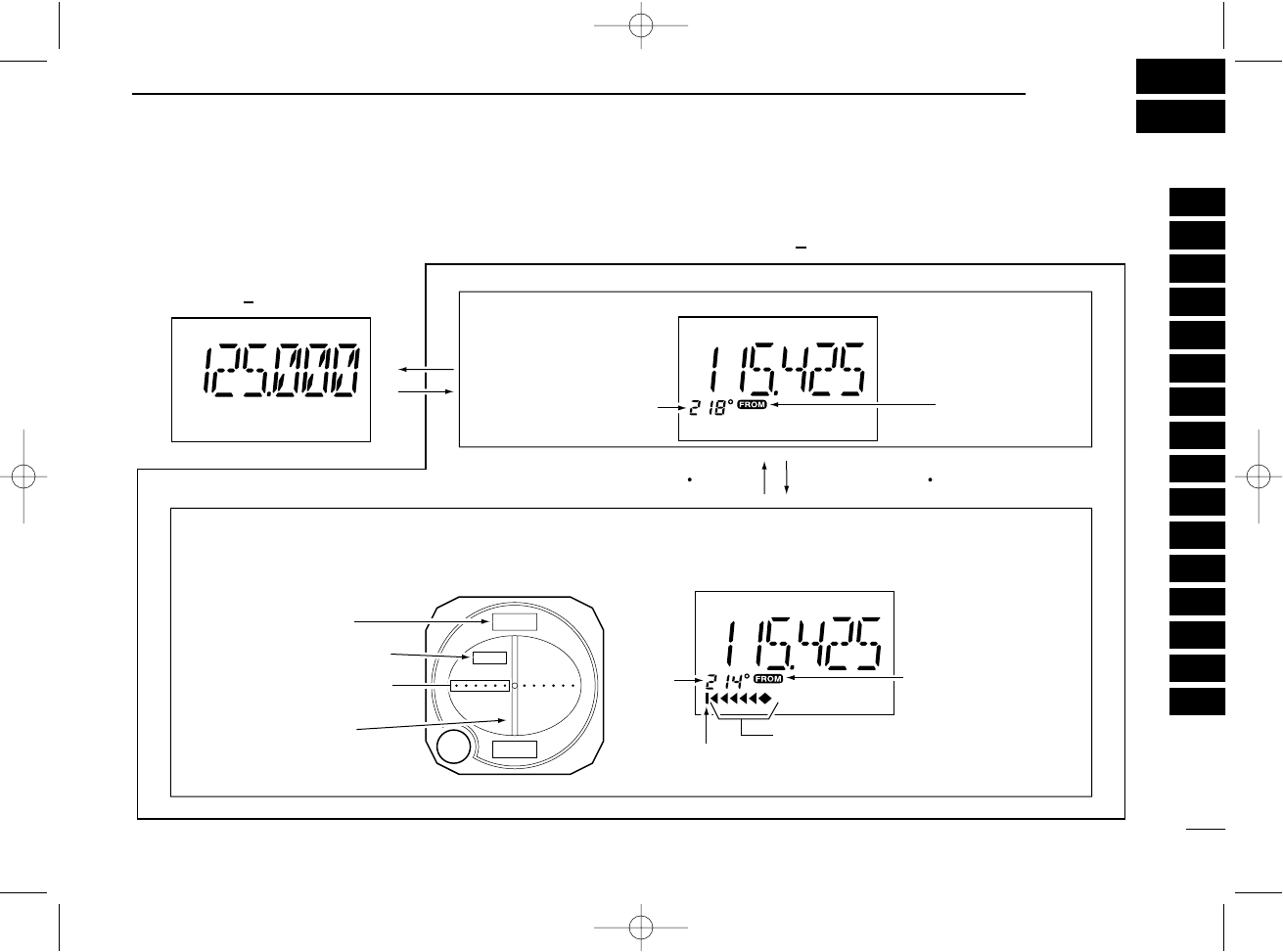
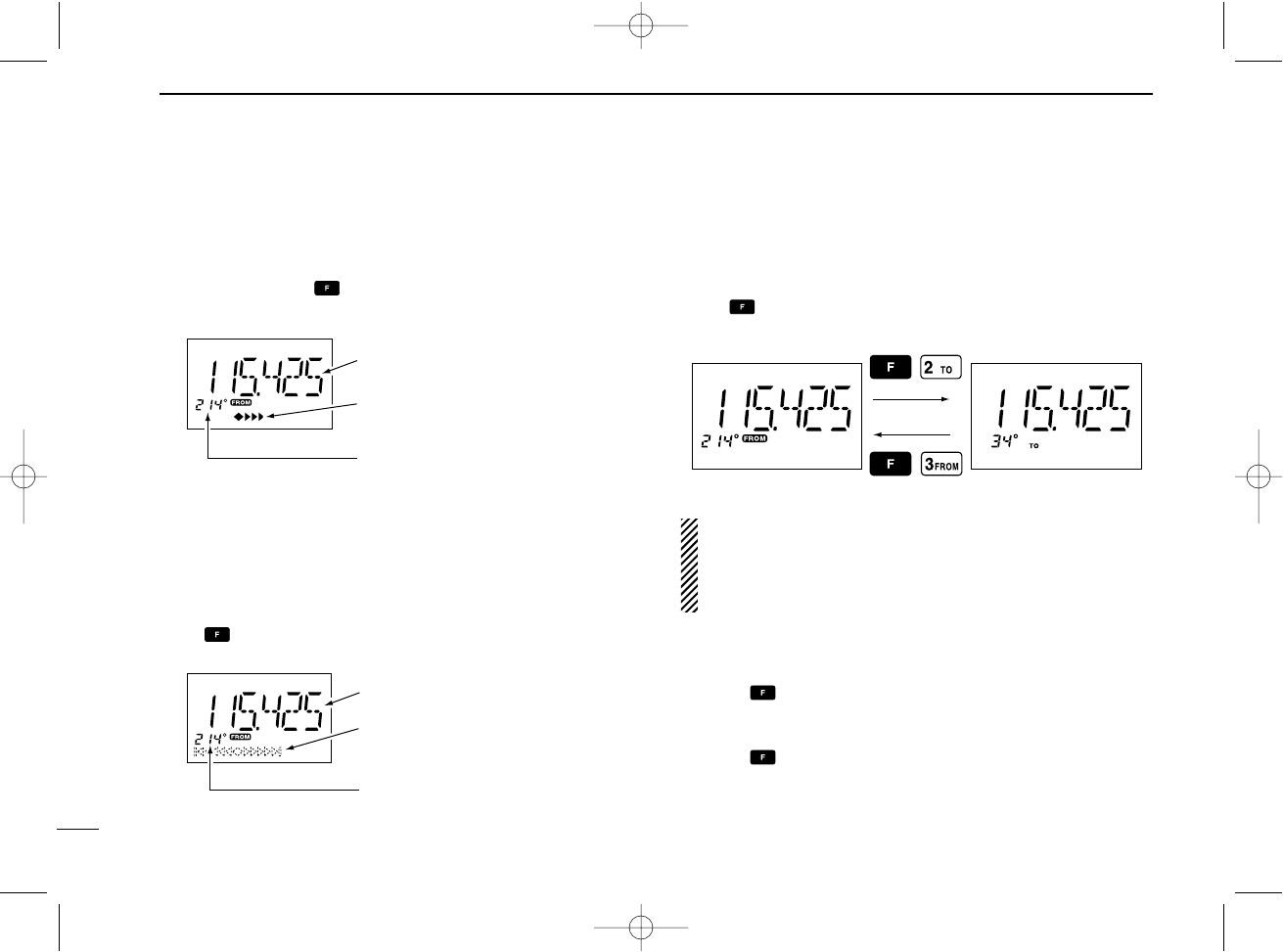
■VOR indicators
214
34
FROM
COM BAND
(118.00 136.975 MHz)
NAV BAND (108.00 117.975 MHz)
DVOR MODE
Function display of the IC-A24General VOR equipment
To-from flag
indicator
CDI MODE
Course indicator
Course
indicator
Course deviation needles
Overflow indicator
Push [F] then [4 CDI].Push [F] then [1 DVOR].
To-from flag indicator
Course indicator
Course deviation
needle
To-from flag indicator
Two-degree deviation
marks
1
2
3
4
5
6
7
8
9
10
11
12
13
14
15
16
IC-A24-Nocl.qxd 04.9.1 5:50 PM Page 19
19
6VOR NAVIGATION (IC-A24 ONLY)
■VOR functions
DTo select the CDI mode
To show the deviation between your flying course and the de-
sired course, push , then push [4•CDI] to select the CDI
mode.
DTo select the DVOR mode
When entering the NAV band, 108.000–117.975 MHz, the
IC-A24 selects the DVOR mode automatically.
To show your aircraft’s direction to (or from) the VOR station,
push , then push [1•DVOR] to select the DVOR mode.
D‘TO’or ‘FROM’flag selection
The to-from flag indicators indicate whether the VOR naviga-
tion information is based on a course leading to the VOR sta-
tion or leading away from the VOR station.
Push , then push [3•FROM] or [2•TO] to change the flag
from ‘TO’to ‘FROM’or vice versa, respectively.
NOTE:
•When using the ‘TO’flag and passing through the VOR station,
the ‘TO’flag changes to the ‘FROM’flag automatically.
•When turning power ON, the ‘FROM’flag is selected automati-
cally.
DSelecting the next VOR station when using
CDI mode (when using the course deviation needle)
qPush , then push [1•DVOR] to select the DVOR mode.
wPush the keypad or rotate [DIAL] to set the next VOR sta-
tion’s frequency.
ePush , then push [4•CDI] to select the CDI mode.
•Select ‘TO’or ‘FROM’flag, if desired.
Operating frequency can not be
changed.
Each course deviation arrow
indicates a two-degree deviation.
Course indicator is fixed, but it
can be changed with the tuning
dial or keypad.
Operating frequency can not be
changed.
Course deviation needle does not
appear.
Course indicator shows your
direction to (or from) the VOR
station.
IC-A24-Nocl.qxd 04.9.1 5:50 PM Page 20
20
6
VOR NAVIGATION (IC-A24 ONLY)
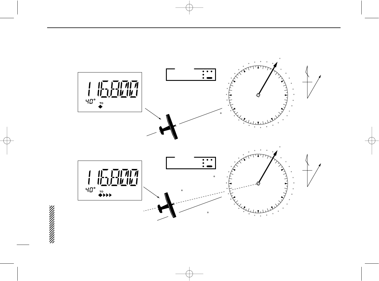
■Flying to a VOR station
The IC-A24 shows the deviation from a VOR station.
qSelect a VOR station on your aeronautical chart and push
the keypad or rotate [DIAL] to set the frequency of the sta-
tion.
•The course indicator indicates where you are located on a radial
from the VOR station.
•The course indicator shows ‘- -’when either aircraft is too far
away from the VOR station or the frequency is not set correctly at
the VOR station.
wSelect the ‘TO’flag when flying to the VOR station, or se-
lect the ‘FROM’flag when flying away from the VOR sta-
tion.
• Push ,then push [2•TO] to select ‘TO’.
• Push ,then push [3•FROM] to select ‘FROM’.
ePush , then push [4•CDI] to select the CDI (Course De-
viation Indicator) mode.
•The course indicator shows ‘OF’when the desired VOR signal
cannot be received.
NOTE: When the CDI mode is selected, the operating fre-
quency cannot be changed. To set the operating fre-
quency, select the DVOR mode in advance.
rThe course deviation needle appears when your aircraft is
off course from the VOR station.
•‘Ω’or ‘≈’appears to indicate your aircraft is off course to the right
or left, respectively. Correct your course until ‘Ω’or ‘≈’disap-
pears. Each arrow represents a two-degree deviation.
tPush , then push [1•DVOR] to exit the CDI mode.
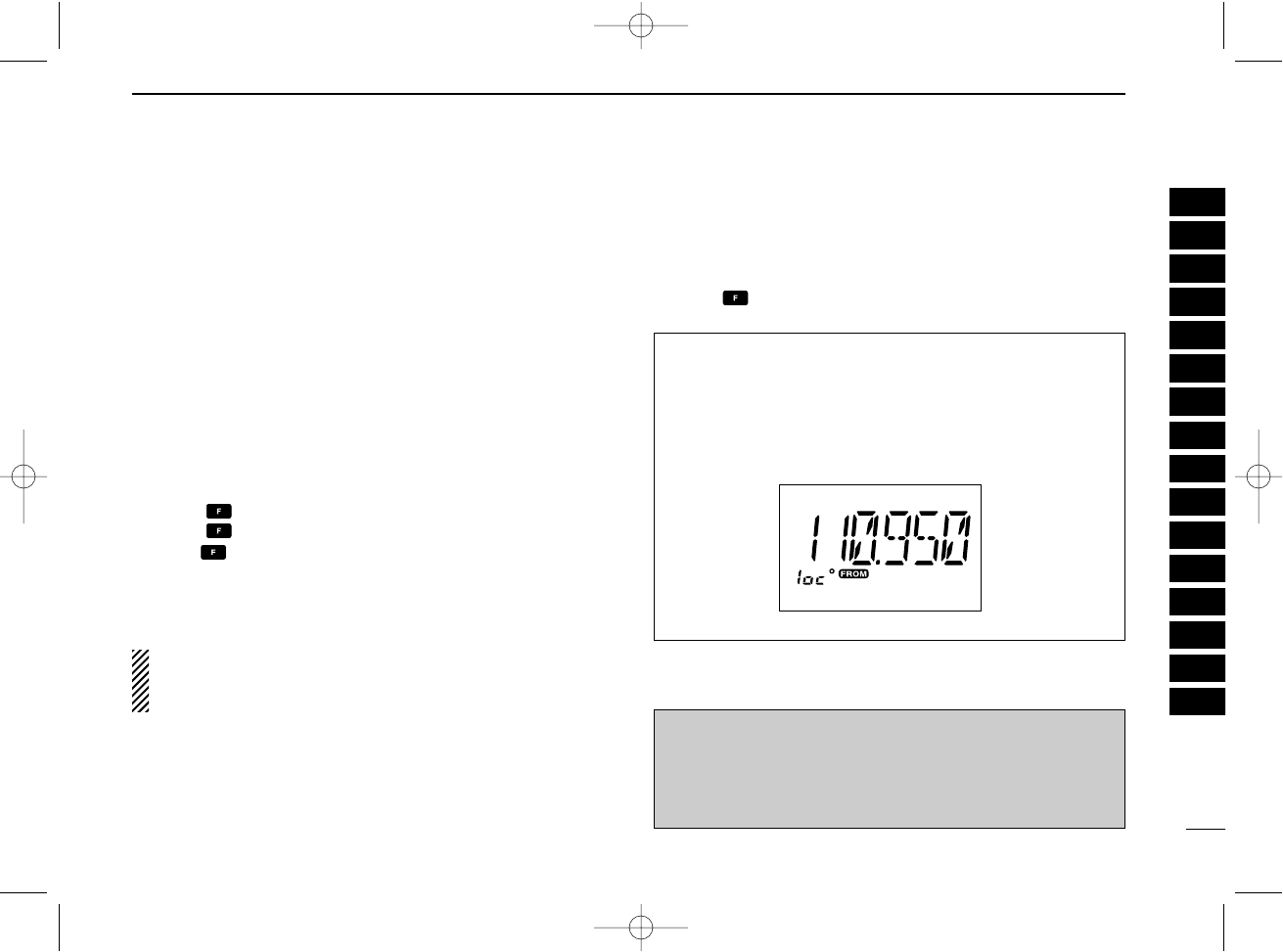
VOR INDICATOR NOTE
‘loc’appears on the function display as shown below when
a localizer signal is received.
However, the function display does not indicate additional
information about the localizer signal.
NOTE: For U.S.A. version only
IC-A24’s VOR and CDI Navigation features are supplemen-
tal aids to navigation only, and are not intended to be a sub-
stitute for accurate (primary) VOR/CDI or landing service
equipment.
1
2
3
4
5
6
7
8
9
10
11
12
13
14
15
16
IC-A24-Nocl.qxd 04.9.1 5:50 PM Page 21
21
6VOR NAVIGATION (IC-A24 ONLY)
VOR
station
0
10
20
30
40
50
60
70
80
90
100
110
120
130
140
150
160
170
180
190
200
210
220
230
240
250
260
270
280
290
300
310 320 330 340
350
NMagnetic
north
Desired course
Aircraft heading 40
123.65
VORTAC
SEATTLE
116.8 Ch 115 SEA
THE AIRCRAFT IS ON COURSE
VOR
station
0
10
20
30
40
50
60
70
80
90
100
110
120
130
140
150
160
170
180
190
200
210
220
230
240
250
260
270
280
290
300
310 320 330 340
350
NMagnetic
north
Aircraft should be
heading 40
Aircraft heading 46
(6 off course)
Flown course
123.65
VORTAC
SEATTLE
116.8 Ch 115 SEA
THE AIRCRAFT IS OFF COURSE
NOTE: The course deviation indica-
tor appears when the aircraft is off
course. In this example, the aircraft is
6 degrees off course to the left. The
pilot must turn more than 6 degrees
right to get back on course.
IC-A24-Nocl.qxd 04.9.1 5:50 PM Page 22
22
6
VOR NAVIGATION (IC-A24 ONLY)
■Entering a desired course
The IC-A24 shows not only the deviation from the VOR sta-
tion but the deviation from the desired course.
qPush the keypad or rotate [DIAL] to set the frequency for
the desired VOR station.
•Push ,then push [2•TO] or [3•FROM] to change the to-from
flag.
wPush , then push [4•CDI] to select CDI mode.
eSet the desired course to the VOR station using the tun-
ing dial or keypad.
•‘Ω’or ‘≈’appears on the function display when your aircraft is off
the desired course.
•When your heading is correct, the ABSS function (see right col-
umn for detail) may be useful instead of course input.
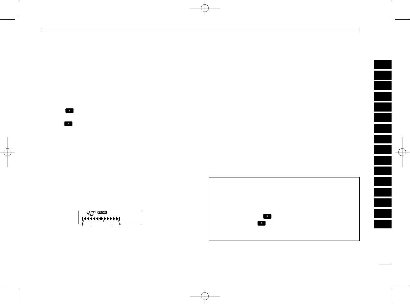
rThe course deviation needle points to the right when your
aircraft is off course to the left.
•To get back on course, fly right more than the number of degrees
indicated by the CDI arrows.
•If the overflow indicator appears on the right side, select a head-
ing plus 10 degrees to the desired course; if the overflow indica-
tor appears on the left side, select a heading minus 10 degrees.
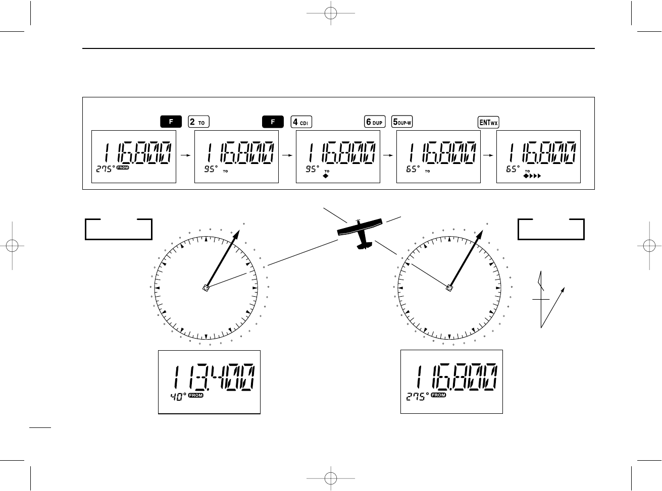
■Crosschecking position
qSelect 2 VOR stations on your aeronautical chart.
wPush the keypad or rotate [DIAL] to set the frequency of
one of the VOR station in the DVOR mode.
•The course indicator shows course deviation from the VOR ra-
dial. Note the radial you are on.
ePush the keypad or rotate [DIAL] to set the frequency of
the other VOR station in DVOR mode.
•Note the radial from the station you are on.
rExtend the radials from each VOR station on the chart.
Your aircraft is located at the point where the lines inter-
sect.
ABSS FUNCTION
In the CDI mode, the Auto Bearing Set System (ABSS)
adds or subtracts the number of degrees indicated by the
CDI arrows from the Omni Bearing Selector (OBS).
To use ABSS, push , then push [2•TO] while using the
‘TO’flag; or, push , then push [3•FROM] while using the
‘FROM’flag.
q
w
Overflow indicator (left)
Overflow indicator (right)
Course deviation needles (left)
e
r
Course deviation needles (right)
wer
q
1
2
3
4
5
6
7
8
9
10
11
12
13
14
15
16
IC-A24-Nocl.qxd 04.9.1 5:50 PM Page 23
23
6VOR NAVIGATION (IC-A24 ONLY)
EXAMPLE: Entering the desired course bearing 65°to a VOR station.
VOR
station
0
10
20
30
40
50
60
70
80
90
100
110
120
130
140
150
160
170
180
190
200
210
220
230
240
250
260
270
280
290
300
310 320 330 340
350
NMagnetic
north
VOR
station
0
10
20
30
40
50
60
70
80
90
100
110
120
130
140
150
160
170
180
190
200
210
220
230
240
250
260
270
280
290
300
310 320 330 340
350
113.4 Ch 81 OLM
VORTAC
OLYMPIA
116.8 Ch 115 SEA
123.65
VORTAC
SEATTLE
CROSSCHECKING POSITION
IC-A24-Nocl.qxd 04.9.1 5:50 PM Page 24
24
6
VOR NAVIGATION (IC-A24 ONLY)
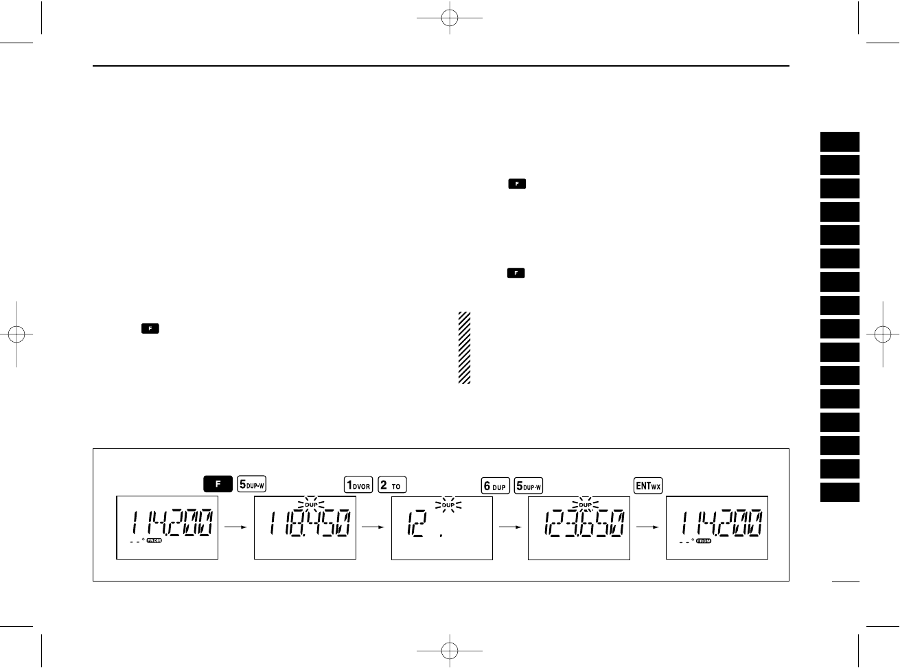
■Duplex operation
(U.S.A. version only)
The duplex function allows you to call a flight service station
while receiving a VOR station. The duplex function requires
frequency programming for the flight service station in ad-
vance.
DProgramming a duplex frequency
qPush [CLR•DEL] to select the frequency mode.
wSet a NAV band frequency using the tuning dial or keypad.
•NAV band frequency range: 108.00–117.975 MHz
ePush , then push [5•DUP-W].
•“DUP” flashes and transmit frequency appears.
rSet the frequency of the flight service station using the tun-
ing dial or keypad. When using the tuning dial, push
[ENT•WX] after setting a frequency.
•The displayed frequency returns to the NAV band frequency.
DOperating the duplex function
qSet the desired frequency in NAV band.
•NAV band frequency range: 108.00–117.975 MHz
wPush , then push [6•DUP] to turn the duplex function
ON.
•“DUP” appears on the function display.
ePush and hold [PTT] to transmit at the pre-programmed
transmit frequency.
rRelease [PTT] to return to receive.
tPush , then push [6•DUP] to cancel the function.
•“DUP” disappears on the function display.
NOTE: A duplex frequency can be programmed into each
memory channel independently. Set a duplex frequency
before programming the memory channel, if desired. The
duplex ON/OFF setting can also be programmed into a
memory channel.
EXAMPLE: Programming 123.65 MHz as the transmit frequency in the duplex function.
1
2
3
4
5
6
7
8
9
10
11
12
13
14
15
16
IC-A24-Nocl.qxd 04.9.1 5:50 PM Page 25

25
7BATTERY PACKS
■Battery charging
Prior to using the transceiver for the first time, the battery
pack must be fully charged for optimum life and operation.
CAUTION: To avoid damage to the transceiver, turn the
power OFF while charging.
• Recommended temperature range for charging:
+10°C to +40°C (+50°F to +104°F)
- The Li-Ion battery is functioning within –20°C to +60°C
(–4°F to +140°F)
• Use the supplied AC adapter on regular charging. NEVER
use another manufacture’s adapters.
• Use the specified chargers (BC-119N, BC-121N and BC-
144N). NEVER use another manufacture’s charger.
NEVER connect DC power to the transceiver when in-
stalling Alkaline batteries. Such a connection will damage
the transceiver.
DRecycling information (U.S.A. only)
The product that you have purchased contains a
rechargeable battery. The battery is recyclable.
At the end of its life, under various state and
local laws, it may be illegal to dispose of this bat-
tery into the municipal waste stream. Call 1-800-
822-8837 for battery recycling options in your
area or contact your dealer.
■Battery cautions
CAUTION! NEVER insert battery pack/transceiver
(with the battery pack attached) with wet or soiled into the
charger. This may result in corrosion of the charger terminals
or damage to the charger. The charger is not waterproof and
water can easily get into it.
NEVER incinerate used battery packs. Internal battery gas
may cause an explosion.
NEVER immerse battery pack in water. If the battery pack
becomes wet, be sure to wipe it dry immediately (particularly
the battery terminals BEFORE attaching it to the transceiver.
NEVER short the terminals of the battery pack. Also, cur-
rent may flow into nearby metal objects, such as a necklace,
etc. Therefore, be careful when carrying with, or placing near
metal objects, carrying in handbags, etc.
If your battery pack seem to have no capacity even after
being charged, completely discharge them by leaving the
power ON overnight. Then, fully charge the battery pack
again. If the batteries still do not retain a charge (or very little),
new battery pack must be purchased.
Turn the transceiver power OFF when charging the battery
pack. Otherwise, the battery pack may not become full-
charging or may not charge properly.
IC-A24-Nocl.qxd 04.9.1 5:50 PM Page 26
26
7
BATTERY PACKS
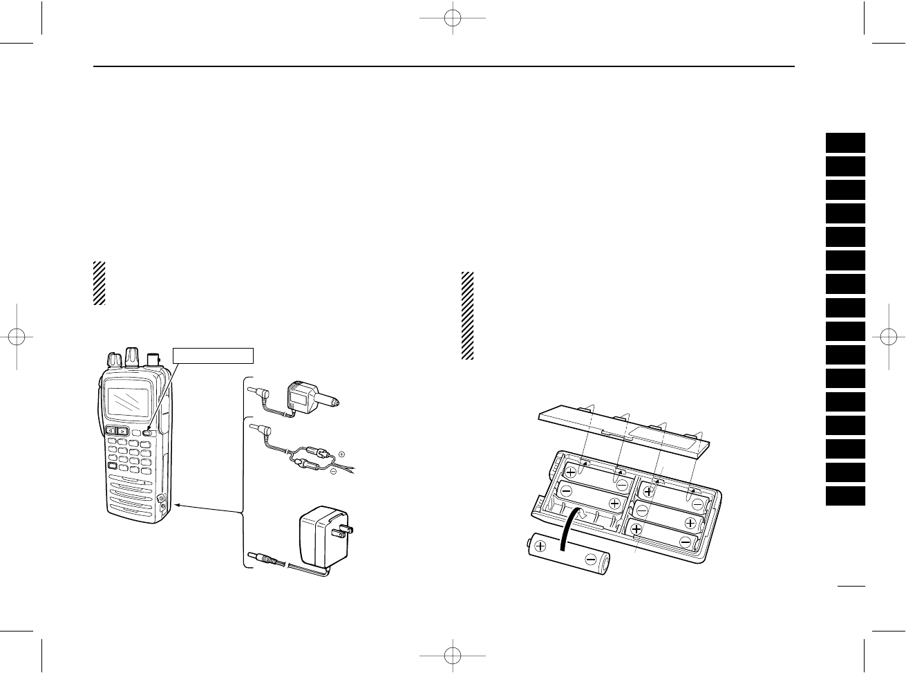
DRegular charging
qAttach the battery pack to the transceiver.
wBe sure to turn the transceiver power OFF.
eConnect the Wall charger or optional cable (CP-12L, CP-
20 or OPC-254L) as shown below.
rCharging the battery pack approx. 8 hours, depending on
the remaining power condition.
DO NOT charge BP-210N more than 12 hours. Otherwise,
BP-210N will be damaged. BP-210N must be charged for
8–12 hours only.
■Optional battery case
When using a battery case attached to the transceiver, install
6 ×AA(R6) size Alkaline batteries as illustrated below.
qRemove the battery case from the transceiver.
wInstall 6 ×AA(R6) size Alkaline batteries.
•Be sure to observe the correct polarity.
CAUTION:
•When installing batteries, make sure they are all the same
brand, type and capacity. Also, do not mix new and old
batteries together.
•Keep battery contacts clean. It’s a good idea to clean bat-
tery terminals once a week.
Wall charger
OPC-254L
(optional)
To
[DC POWER
JACK]
white
black
IC-A24/A6 with at-
tached battery pack
To a 12 to 14 V DC
power source
CP-12L (for 12 V) or
CP-20 (for 24 V)
(optional) To the cigarette
lighter socket
Turn power OFF
1
2
3
4
5
6
7
8
9
10
11
12
13
14
15
16
IC-A24-Nocl.qxd 04.9.1 5:50 PM Page 27
27
7BATTERY PACKS
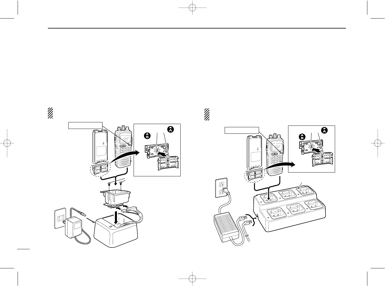
■Optional battery chargers
DRapid charging with the BC-119N+AD-101
The optional BC-119N provides rapid charging of battery
packs. The following are additionally required.
• AD-101 charger adapter.
• An AC adapter (may be supplied with BC-119N depending on ver-
sions) or the DC power cable (OPC-254L/CP-17L).
NOTE: Attach the spacer (Spacer B/C) to the adapter (Spacer
A) with orientation as illustrated below.
DRapid charging with the BC-121N+AD-101
The optional BC-121N allows up to 6 battery packs to be
charged simultaneously. The following are additionally re-
quired.
• Six AD-101 charger adapters.
• An AC adapter (BC-124) or the DC power cable (OPC-656).
NOTE: Attach the spacer (Spacer B/C) to the adapter (Spacer
A) with orientation as illustrated below.
AD-99 (supplied
with AD-101)
AD-101
(optional)
Supplied screws
with AD-101.
BC-119N
(optional)
IC-A24/A6
BP-209N/BP-210N/
BP-211N
Turn power OFF
Spacer A
Spacer B/C
Check orientation
and
IC-A24/A6
BP-209N/BP-210N/
BP-211N
AC adapter
(BC-124:
Purchase
separately)
AD-101 charger adapters are
installed in each slot.
DC power cable (OPC-656)
(Connect with the DC power supply;
13.8 V/at least 7 A)
Turn power OFF
AD-99 (supplied
with AD-101)
Spacer A
Spacer B/C
Check orientation
and
IC-A24-Nocl.qxd 04.9.1 5:50 PM Page 28
28
8
CLONING
Cloning allows you to quickly and easily transfer the
programmed data from one transceiver to another
transceiver, or, data from PC to a transceiver using the
optional CS-A24 cloning software.
DTransceiver to transceiver cloning
qConnect the OPC-474 CLONING CABLE with adapter plugs
to [SP/MIC] jack of the master and slave transceivers.
•The master transceiver is used to send data to the slave trans-
ceiver.
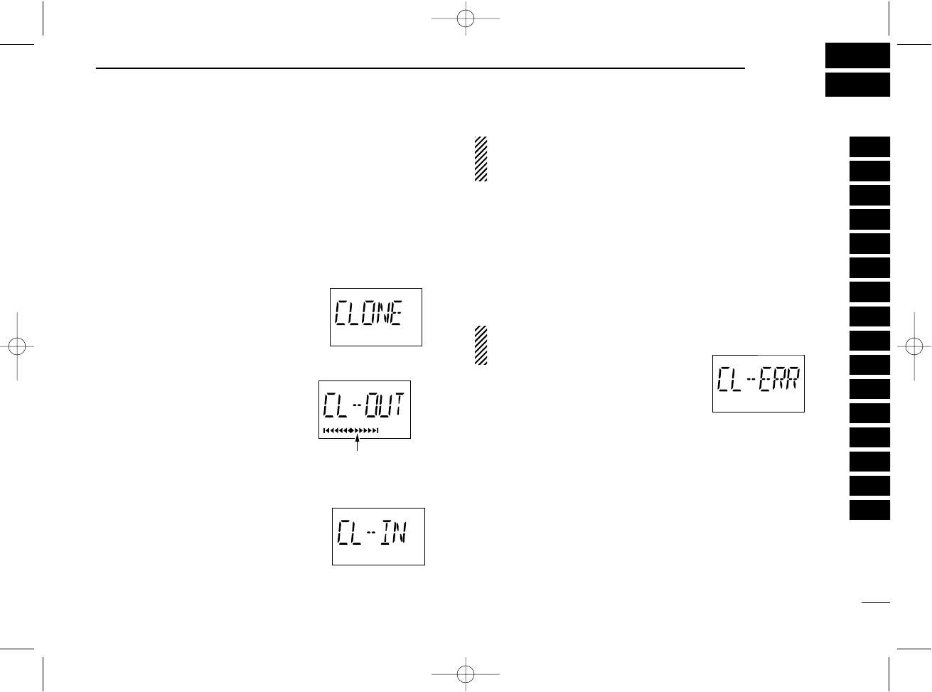
wWhile push and holding [MR•MW],
push [PWR] to enter cloning mode
(for operating the master transceiver
only).
•“CLONE” appears and the transceivers
enter the clone standby condition.
ePush [MR•MW] on the master trans-
ceiver.
•“CL-OUT” appears in the master trans-
ceiver’s display.
• “COURSE DEVIATION NEEDLES”
shows that cloning is taking place
•“CL-IN” appears automatically in the
slave transceiver’s display.
rWhen cloning is finished, turn power OFF, then ON again
to exit cloning mode.
NOTE: DO NOT transfer the data from IC-A24 to IC-A6,
when the data contains the NAV band data. In such case,
cloning error may occur.
DCloning using PC
Data can be cloned to and from a PC (Microsoft®, Windows®
98/98SE/Me/2000/XP) using the optional CS-A24 CLONING
SOFTWARE and the optional OPC-478 (RS-232C type) or
OPC-478U (USB type) CLONING CABLE. Consult the CS-A24
CLONING SOFTWARE HELP file for details.
DCloning error
NOTE: DO NOT push [ENT•WX] on the slave transceiver
during cloning. This will cause a
cloning error.
When the display at right appears, a
cloning error has occurred.
In this case, both transceivers automatically return to the
clone standby condition and cloning must be repeated.
Microsoft and Windows are registered trademarks of Mi-
crosoft Corporation in the U.S.A. and other countries.
1
2
3
4
5
6
7
8
9
10
11
12
13
14
15
16
“COURSE DEVIATION
NEEDLES” shows that
cloning is taking place.
IC-A24-Nocl.qxd 04.9.1 5:50 PM Page 29
29
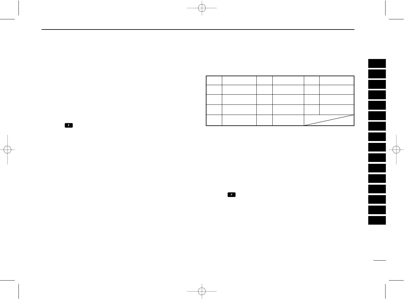
9TROUBLESHOOTING
If your transceiver seems to be malfunctioning, please check
the following points before sending it to a service center.
PROBLEM POSSIBLE CAUSE SOLUTION REF.
No power comes on. • The battery is exhausted. • Recharge the battery pack. pgs. 7,
• Bad connection for the battery pack. • Check the connection to the transceiver. 25–27
No sound comes from • Squelch level is too deep. • Set squelch to the threshold point. pgs. 8, 9
the speaker. • Volume level is too low. • Set [VOL] to a suitable level.
Transmitting impossible. • Some channels are receive only. • Change channels. p. 8
• The battery is exhausted. • Recharge the battery pack. p. 25–27
The display channel • Lock function is activated. • Push , then push [7•]. p. 11
can not be selected.
Scan does not start. • All memory channels are not programmed • Set the “TAG” settings of desired p. 17
programmed as “TAG” channels. channels.
No beep sounds. • Beep tones turned OFF. • Push , then push [8•BEEP] to adjust p. 11
the beep tone level
IC-A24-Nocl.qxd 04.9.1 5:50 PM Page 30

30
10
SPECIFICATIONS
DGeneral
•Frequency coverage (MHz): TX 118.000 to 136.975
RX 108.000 to 136.975*1
WX 161.650 to 163.275*2
*1: IC-A24 only, IC-A6; 118.000 to 136.975 MHz
*2: U.S.A. version only.
•Mode : 6K00A3E
16K0G3E (161.65 to 163.275 MHz)
•Channel spacing : 25 kHz
•Number of memory channels : 200 (20 CH. ×10 BANK)
•Power supply requirement : Specified battery packs/case or
11.0 V DC at external DC jack
•Usable temp. range : –10˚C to +60˚C (+14°F to +140°F)
•Current drain :
Tx 1.5 A typical
Rx 70 mA typical (at stand by)
300 mA typical.(at AF max.)
•Antenna connector : BNC 50 Ω(nominal)
•Dimensions : 54(W)×129.3(H)×35.5(D) mm
(projections not incl.)
21⁄8(W) ×53⁄32(H) ×113⁄32(D) inch
•Weight : Approx. 180 g (6.35 oz)
(Without the battery pack and antenna.)
DTransmitter
•Output power : 5 W (PEP) typical
1.5 W (CW) typical
•Modulation : Low level modulation
•Modulation limiting : 70 to 100%
•Audio harmonic distortion :
Less than 10% (at60 % mod.)
•Hum and noise ratio : More than 35 dB
•Spurious emissions : More than 46 dB (except oper-
ating frequency ±6.25 Hz range)
•Microphone connector : 3-conductor 2.5(d) mm (1/10˝)/
more than 100 kΩ
DReceiver
•Receive system : Double conversion
superheterodyne
•Intermediate frequencies : 1st 30.05 MHz
2nd 450 kHz
•Sensitivity
VOR (AM 6dB S/N)
: Less than –3 dBµ typical
COM (AM 6dB S/N)
: Less than –6 dBµ typical
WX (FM 12dB SINAD)
: Less than –13 dBµ typical
•Squelch sensitivity : AM Less than 0 dBµ
FM Less than –7 dBµ
•Selectivity : More than 7.5 kHz/–6 dB)
Less than 25 kHz/–60 dB)
•Spurious response : AM More than 60 dB
rejection FM More than 30 dB
•Audio output power : More than 500 mW typical
(at 10% distortion with an 8 Ω
load, 30% mod.)
•Noise and hum : More than 40 dB at 30% mod.
•External SP connector : 3-conductor 3.5 (d) mm
(1/8˝)/8 Ω
All stated specifications are subject to change without
notice or obligation.
1
2
3
4
5
6
7
8
9
10
11
12
13
14
15
16
IC-A24-Nocl.qxd 04.9.1 5:50 PM Page 31

31
11 OPTIONS
DBATTERY CASE AND PACKS
•BP-208N
BATTERY CASE
Battery case for 6 ×AA (R6) Alkaline cells.
•BP-209N Ni-Cd
BATTERY PACK
7.2 V/1100 mAh Ni-Cd battery pack.
•BP-210N Ni-MH
BATTERY PACK
7.2 V/1650 mAh Ni-MH battery pack.
•BP-211N Li-Ion
BATTERY PACK
7.4 V/1800 mAh Li-Ion battery pack.
DCHARGERS
•BC-110AR/DR
WALL CHARGER
The same as supplied with the transceiver.
•BC-119N
DESKTOP CHARGER
+ AD-101
CHARGER ADAPTER
+ BC-145
AC ADAPTER
For rapid charging of battery packs. An AC adapter is supplied with
the charger depending on versions. Charging time: approx. 1.5 to 2
hours.
•BC-121N
MULTI
-
CHARGER
+ AD-101
CHARGER ADAPTER
(6 pcs.)
+ BC-124
AC ADAPTER
For rapid charging of up to 6 battery packs (six AD-101’s are re-
quired) simultaneously. An AC adapter should be purchased sepa-
rately. Charging time: approx. 1.5 to 2 hours.
•BC-144N
DESKTOP CHARGER
For rapid charging of BP-209N (Ni-Cd) and BP-210N (Ni-MH).
DBELT CLIPS
•MB-103
BELT CLIP
The same as supplied with the transceiver.
•MB-86
SWIVEL BELT CLIP
Belt clip for swivel type.
•MB-96F/96N
LEATHER BELT HANGER
➥MB-96F: Attaches with the supplied belt clip (Fixed type).
➥MB-96N: Belt hanger for swivel type.
DDC CABLES
•CP-17L
CIGARETTE LIGHTER CABLE
Allows to charge the battery pack through a 12 V cigarette lighter
socket. (For BC-119N)
•OPC-254L
DC POWER CABLE
For operation and charging via an external power supply.
•OPC-656
DC POWER CABLE FOR
BC-121N
WITH DC
Allows to charge the battery pack using 13.8 V power source in-
stead of the AC adapter for BC-121N.
DOTHER OPTIONS
•OPC-499
HEADSET ADAPTER CABLE
When using an optional headset, such as those from the David
Clark Co. via the adapter, the transceiver outputs your transmitted
voice to the headset for monitoring.
•LC-159
CARRYING CASE
Helps protect the transceiver from scratches, etc.
Usable options are depended on versions. Ask your dealer
or distributor for details.
IC-A24-Nocl.qxd 04.9.1 5:50 PM Page 32
OPERATION GUIDE
iA24/A6
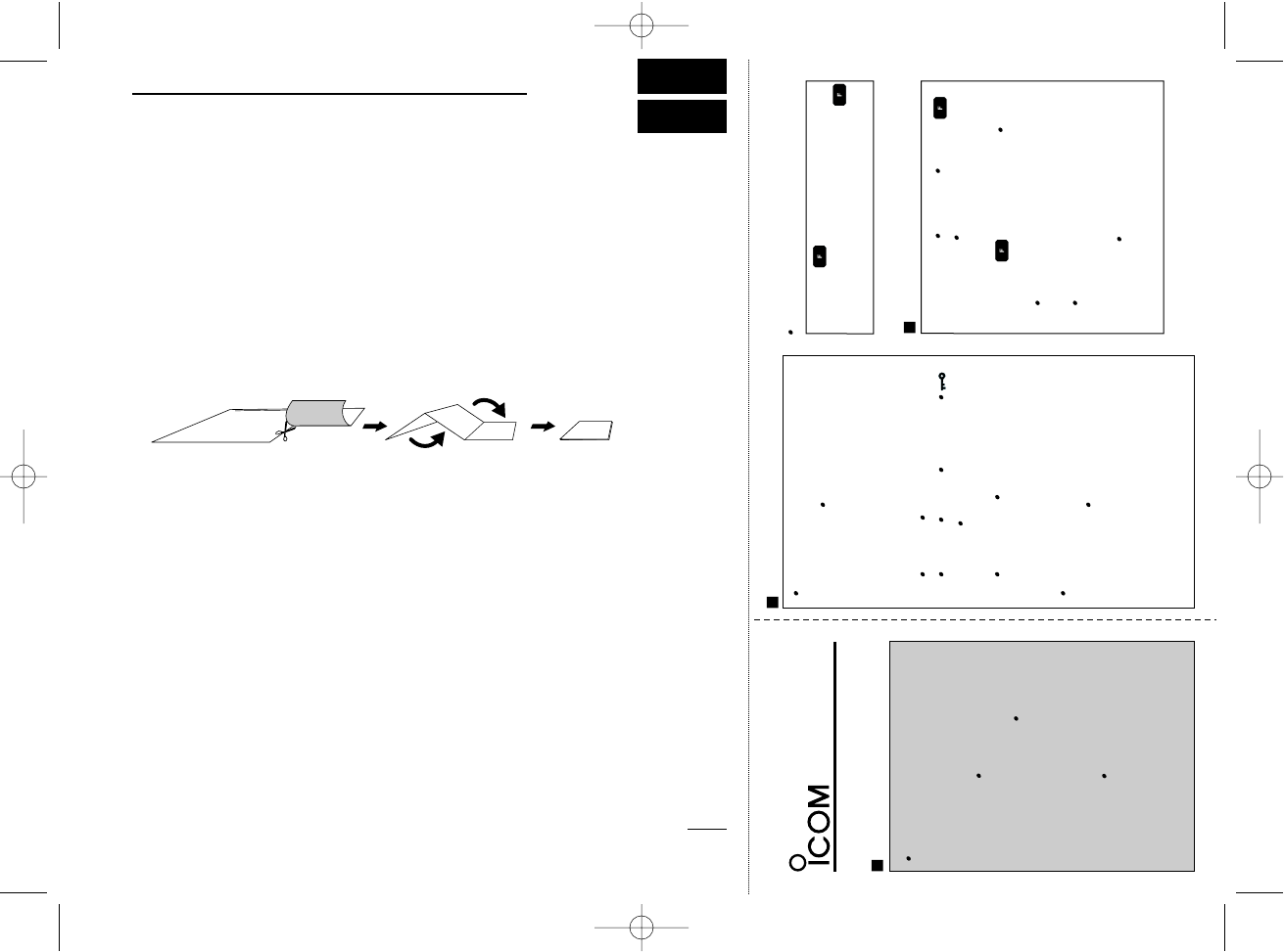
SETTING A FREQUENCY (p. 8)
BEGINNING OPERATION
(p. 9)
Using the keypad
Turning the power ON.
q
w
Push [CLR
DEL
] to select the fre-
quency mode when memory CH or
WX CH* appears on the display.
Rotate [DIAL] to select the desired
frequency.
q
w
e
r
Push [PWR] for 2 sec. to turn
the power ON or OFF.
Push [SQL
WX-ALERT
], then ro-
tate [VOL] to adjust the squelch
level ‘0.’ Push [SQL
WX-ALERT
]
to exit the squelch set mode.
Rotate [VOL] to adjust the de-
sired audio level.
Push [SQL
WX-ALERT
], then ro-
tate
[VOL]
to adjust the squelch
level.
Push [CLR
DEL
] to select the fre-
quency mode when memory CH or
WX CH* appears on the display.
Push 5 appropriate digit keys to in-
put the frequency.
Enter [1
DVOR
] as the 1st digit.
Only [2
TO
], [5
DUP-W
], [7
]
and [0
BANK
] can be entered as
the 5th and final digit.
Push [CLR
DEL
] , when a digit is
mistakenly input.
Using [DIAL]
q
w
Push , then rotate [DIAL] to se-
lect the 1 MHz tuning step. Push
to cancel the function.
e
SETTING A FREQUENCY
Using [DIAL] (Continued)
SCAN (pgs. 16, 17)
q
w
e
Push [CLR
DEL
], [MR
MW
] or ,
then [ENT
WX
]* to select the fre-
quency, memory or WX CH* mode.
Push , then push [ANL
SCAN
]
to start scanning.
Decimal point blinks during scan-
ning.
Rotate [DIAL] to change the scan-
ning direction.
Push [CLR
DEL
] to cancel the scan-
ning.
32
12
QUICK REFERENCE
Important operating instructions are summed up in this and the following page
for your simple reference.
By cutting along the line and folding on the dotted line, it will become a card
sized operating guide which can easily be carried in a card case or wallet,
etc.
q Cut w Fold e Complete
<CUT HERE>
IC-A24-Nocl.qxd 04.9.1 5:50 PM Page 33
33
12 QUICK REFERENCE
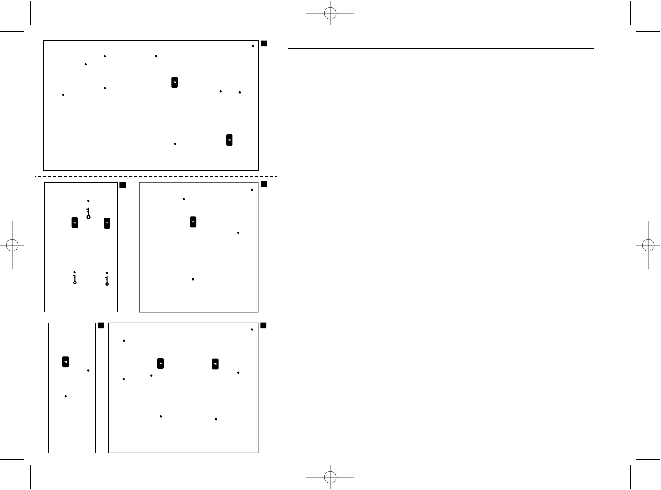
Transferring memory contents
MEMORY OPERATION (p. 13) MEMORY OPERATION (p. 12)
q
w
e
r
t
Push [CLR
DEL
] to select the fre-
quency mode or push , then
push [ENT
WX
] to select WX CH*
mode.
Select the desired frequency or WX
CH.*
Push , then push [MR
MW
] to
enter memory programming mode.
“M”, BANK and memory numbers
blink on the display.
Rotate [DIAL] (or push keypad) to
select a desired memory CH num-
ber (0 to 19).
Push [0
BANK
], then select the
BANK number if desired. Push
[0
BANK
] to exit the BANK selec-
tion mode.
Push [ENT
WX
] to program the
memory contents.
q
w
e
Push [MR
MW
] to enter memory
mode.
Select the desired channel to be
transferred.
Push , then push [MR
MW
].
BANK number and memory CH
number disappears as frequency
mode is automatically selected
and the memory contents are
transferred.
MEMORY OPERATION (p. 12)
TAG CHANNELS (p. 17)
q
w
Push [MR
MW
] to select the mem-
ory mode.
Push , then [9
TAG
] to turn the
channel “TAG” ON and OFF.
LOCK FUNCTION (p. 9)
Push ,Then push [7 ] to turn
the key lock function ON.
“ ” appears on the display.
Push ,Then push [7 ] to turn
the keylock function OFF.
q
w
Memory programming
*WX CH available U.S.A. version only.
Memory BANK/CH selection
Push [MR•
MW
] to enter the mem-
ory CH mode.
Push , then push [0
BANK
] to
enter the BANK selection mode.
Push keypad (or rotate [DIAL]) to
select the desired BANK number
(BANK 0 to 9).
Push , then push [0
BANK
] (or
push [ENT
WX
]) to set the BANK
number and exit the BANK selec-
tion mode.
Push [CLR
DEL
] to exit the BANK
selection mode.
q
w
e
IC-A24-Nocl.qxd 04.9.1 5:50 PM Page 34
34
13
OPTIONAL HEADSET CONNECTION
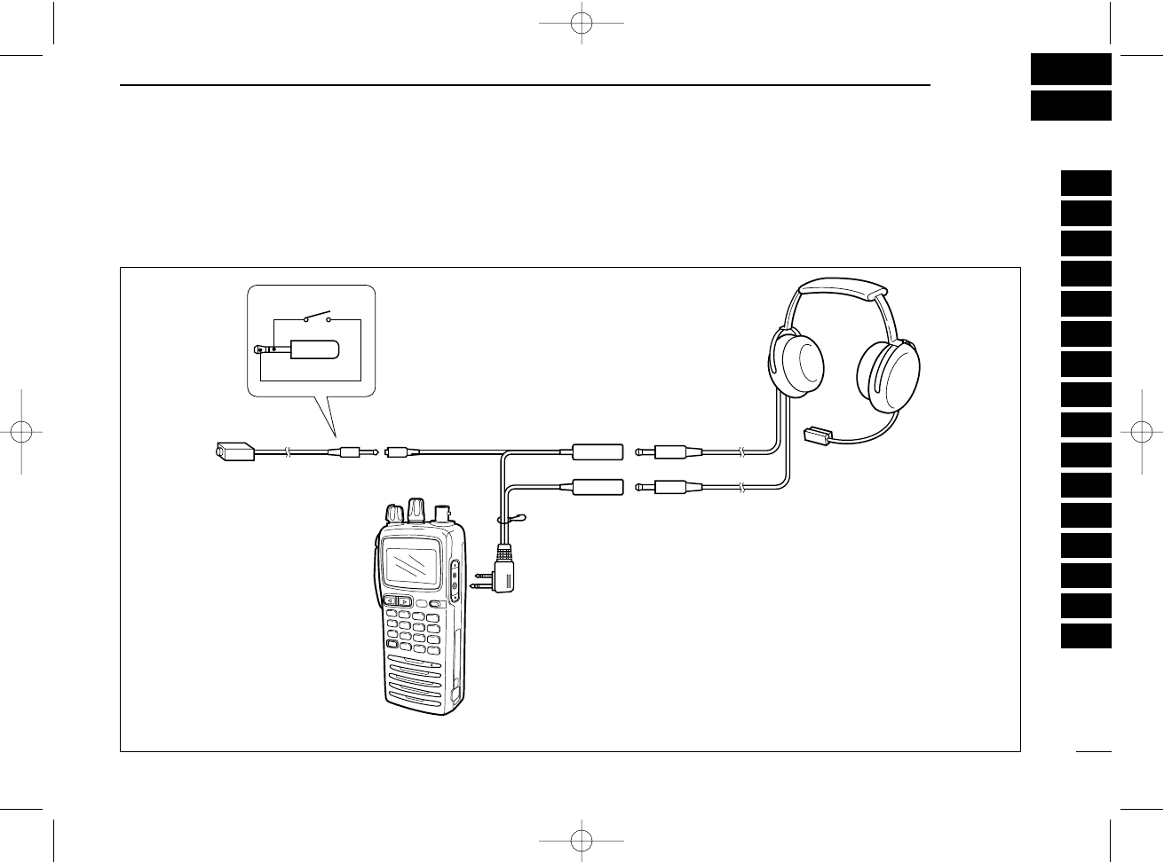
DOPC-499 (HEADSET ADAPTER) connection
When using a headset, such as those from the David Clark Co. via the OPC-499 HEADSET ADAPTOR adapter, the transceiver out-
puts your transmitted voice to the headset for monitoring. See “■Side tone function “(p. 11) when setting the side tone level.
PTT
OPC-499
IC-A24/A6
PTT switch
HEADSET
(Must be purchased
separately)
Use a PTT switch with a
3.5 mm (1/8") diameter
plug, if required.
1
2
3
4
5
6
7
8
9
10
11
12
13
14
15
16
IC-A24-Nocl.qxd 04.9.1 5:50 PM Page 35
1-1-32 Kamiminami, Hirano-ku, Osaka 547-0003 Japan
A-6403D-1EX
Printed in Japan
© 2004 Icom Inc.
IC-A24-Nocl.qxd 04.9.1 5:50 PM Page 36