ICOM orporated 279501 IC-M90 VHF Marine Transceiver User Manual IC M90 instruction manual
ICOM Incorporated IC-M90 VHF Marine Transceiver IC M90 instruction manual
UserManual.wiki
>
ICOM orporated
>
279501 User Manual
User Manual
Navigation menu
Upload a User Manual
Namespaces
Wiki Guide
HTML
PDF
Info
Views
User Manual
Discussion / Help
Navigation
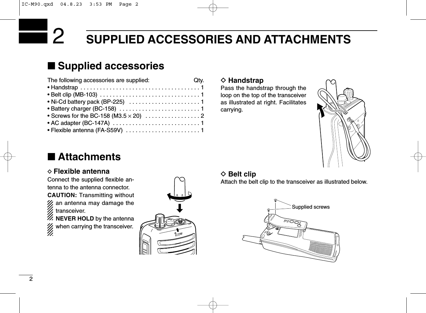
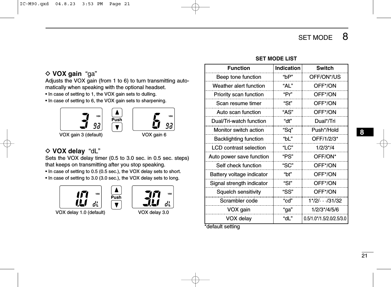
![4PANEL DESCRIPTION3■Front, top and side panelsqVOLUME CONTROL [VOL]Turns power ON and adjusts the audio level.wMICROPHONE CONNECTOR [SP MIC]Connects the optional external microphone.NOTE: Attach the [SP MIC] cap when the optionalspeaker-microphone is not used.eANTENNA CONNECTORConnects the supplied antenna.rTRANSMIT/RECEIVE INDICATORLights green while receiving a signal or when the squelchis open; lights red while transmitting.tCHANNEL/WEATHER CHANNEL SWITCH[CH/WX•U/I/C/L]•Selects and toggles the regular channels and weatherchannel when pushed. (p. 8)•Selects one of 4 regular channels in sequence whenpushed for 1 sec. (pgs. 8, 15)- U.S.A., International, Canadian and Land channels areavailable.•Push to return to the condition before selecting the chan-nel when the priority channel or the call channel is se-lected.ySCAN SWITCH [SCAN•DUAL]•Starts and stops normal or priority scan when pushed.(pgs. 12, 13)•Enters watch mode when pushed for 1 sec. (p. 14)MIC /SPqerytwiuo!1!0IC-M90.qxd 04.8.23 3:53 PM Page 4](https://usermanual.wiki/ICOM-orporated/279501/User-Guide-474596-Page-10.png)
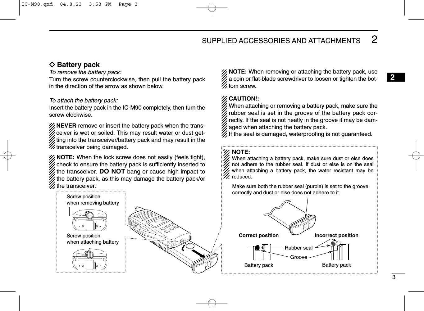
![53PANEL DESCRIPTIONuTRANSMIT POWER/LOCK SWITCH [Hi/Lo•]•Selects high, middle or low power when pushed. (p. 9)•Toggles the lock function ON/OFF when pushed for1 sec. (p. 10)iCHANNEL 16 SWITCH [16•9]•Selects Channel 16 when pushed. (p. 7)• Selects call channel when pushed for 1 sec. (p. 7)• Enters call channel write mode when the call channel isselected and this switch is pushed for 3 sec. (p. 10)oCHANNEL UP/DOWN SWITCHES [YY]/[ZZ]•Selects an operating channel. (pgs. 7–9)•Selects the SET mode condition of the item. (p. 16)•Selects the SET mode item when pushed with [SQL].(p. 16)• Checks tag channels or changes scanning direction dur-ing scan. (p. 13)!0 SQUELCH SWITCH [SQL•MONI]•Push this switch, then adjust the squelch level with[YY]/[ZZ]. (p. 11)• Manually opens the squelch for monitoring the channelwhile pushed and held. (p. 10)•While pushing this switch, turn power ON to enter the setmode. (p. 16)!1 PTT SWITCH [PTT]Push and hold to transmit; release to receive.■Function displayqSIGNAL STRENGTH INDICATOR (pgs. 10, 20)Shows the relative signal strength while receiving signals.wTRANSMIT POWER INDICATOR• “LOW” appears when low power is selected.• “MID” appears when middle power is selected.• No indication appears when high power is selected.eTAG CHANNEL INDICATOR (p. 13)Appears when tag channel is selected.rSQUELCH LEVEL INDICATOR (p. 11)Show the squelch level.q r t yw e!4!6!5uio!0!1!2!3!8!73IC-M90.qxd 04.8.23 3:53 PM Page 5](https://usermanual.wiki/ICOM-orporated/279501/User-Guide-474596-Page-11.png)
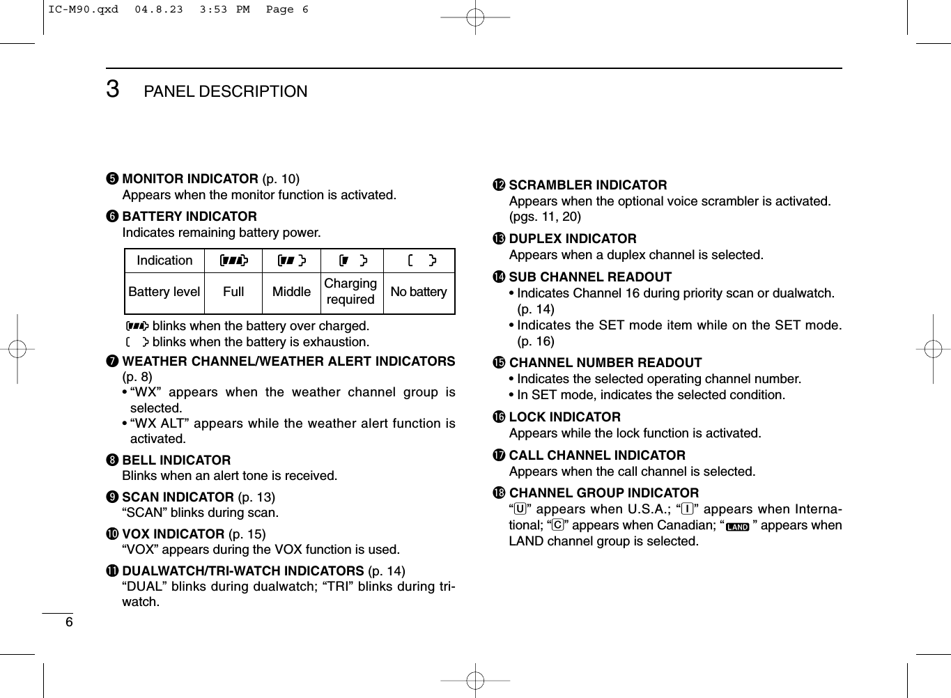
![74BASIC OPERATION34■Channel selectionIMPORTANT!: Prior to using the transceiver for the firsttime, the battery pack must be fully charged for optimumlife and operation. To avoid damage to the transceiver, turnthe power OFF while charging.DChannel 16Channel 16 (Distress channel) is used for establishing initialcontact with another station and for emergency communica-tions. Channel 16 is automatically monitored during bothdualwatch and tri-watch. While standing by, you must monitorChannel 16.qPush [16•9] to select Channel 16.wPush [CH/WX•U/I/C/L] to return to the condition before se-lecting Channel 16, or push [Y]/[Z] to select the operatingchannel.DChannel 9 (Call channel)Channel 9 is the leisure-use call channel. Each regularchannel group has separate call channels. In addition, the callchannel is monitored during tri-watch. The call channels canbe re-programmed (p. 10) and are used to store your mostoften used channels in each channel group for quick recall.qPush [16•9] to select the call channel.•“CALL” and the call channel number appear.•Call channel can be re-programmed. See the “Call channelprogramming” on p. 10 for details.wPush [CH/WX•U/I/C/L] to return to the condition before se-lecting Channel 9 (call channel), or push [Y]/[Z] to selectthe operating channel.PushPushIC-M90.qxd 04.8.23 3:53 PM Page 7](https://usermanual.wiki/ICOM-orporated/279501/User-Guide-474596-Page-13.png)
![Push for 1 sec.U.S.A. channelsInternational channels Canadian channels*84BASIC OPERATIONDU.S.A., International and Canadian channelsThe IC-M90 has 57 U.S.A., 57 International and 61 Canadianchannels. These channel groups may be specified for the op-erating area.qPush [CH/WX•U/I/C/L] to select the regular channel.•If the weather channel appears, push [CH/WX•U/I/C/L] again.wPush [Y]/[Z] to select a channel.•“DUP” appears for duplex channels.eTo change the channel group, push [CH/WX•U/I/C/L] for 1sec.•U.S.A., International and Canadian channels can be selected insequence. Depending on the setting, LAND channel can be se-lected. See the “LAND CHANNEL OPERATION” on p. 15 for de-tails.DWeather channelsThe IC-M90 are 10 weather channels. They are used formonitoring weather channels from the NOAA (NationalOceanographic and Atmospheric Administration) broadcasts(reception of weather channels possible in U.S.A. only).qPush [CH/WX•U/I/C/L] to select the weather channel group.wPush [Y]/[Z] to select a weather channel.ePush [CH/WX•U/I/C/L] to return to the condition before se-lecting the weather channel group.✔CONVENIENT!The IC-M90 can detect a weather alert tone on theselected weather channel while in another channel (when thepower save function is turned ON) or during scanning. Seethe “SET mode items” on p. 17 for details.PushIC-M90.qxd 04.8.23 3:53 PM Page 8](https://usermanual.wiki/ICOM-orporated/279501/User-Guide-474596-Page-14.png)
![94BASIC OPERATION4■Receiving and transmittingqRotate [VOL] clockwise to turn power ON.wUseSet the volume and squelch level.➥Push [SQL•MONI], and push [√] to open the squelch.➥Push [SQL•MONI] to stop “SQL” indicator blinking, thenrotate [VOL] to set the volume level.➥Push [SQL•MONI], and push [∫]/[√] to set the squelchlevel.ePush [Y]/[Z] to select the desired channel.- When receiving a signal, the [TRANSMIT/RECEIVE] indicatorlights green while audio is emitted from the speaker.- Further adjustment of [VOL] may be necessary at this point.rPush [Hi/Lo•] to select the output power if necessary.- “LOW” appears when low power is selected; “MID” appearswhen middle power is selected; no indication when high power isselected.- Choose low power to conserve battery power, choose highpower for longer distance communications.- Some channels are for low power only.tPush and hold [PTT] to transmit, then speak into themicrophone.- The [TRANSMIT/RECEIVE] indicator lights red whiletransmitting.- Channel 70 cannot be used for transmission.yRelease [PTT] to receive.IMPORTANT: To maximize the readability of your trans-mitted signal, pause a few sec. after pushing [PTT], holdthe microphone 5 to 10 cm (2 to 4 inches) from your mouthand speak into the microphone at a normal voice level.NOTE: The transceiver has a power save function to con-serve the battery power. The power save function activatesautomatically when no signal is received for 5 sec.To prevent accidental prolonged transmission, etc., the IC-M90 has a time-out timer function. This timer cuts a trans-mission OFF after 5 min. of continuous transmission.CAUTION: Transmitting without an antenna maydamage the transceiver.MIC /SPq Power ONe Set volumeSpeakery Push to transmitu Release to receiver Set channelw Set the squelch levelw Set the squelch levele Set volumeMicrophonet Set output powerIC-M90.qxd 04.8.23 3:53 PM Page 9](https://usermanual.wiki/ICOM-orporated/279501/User-Guide-474596-Page-15.png)
![104BASIC OPERATION■Call channel programmingThe call channel switch is used to select Channel 9 by de-fault, however, you can program your most often-used chan-nel in each channel group for quick recall.qPush [CH/WX•U/I/C/L] for 1 sec. toseveral times to select the desiredchannel group (USA, INT, CAN) tobe programmed.wPush [16•9] for 1 sec. to select thecall channel.•“CALL” and call channel numberappear.ePush [16•9] again for 3 sec. (until along beep changes to 2 short beeps)to enter call channel programmingcondition.•Call channel number to be programmedflashes.rPush [Y]/[Z] to select the desiredchannel.tPush [16•9] to program the displayedchannel as the call channel.•The call channel number stopflashing.■Lock functionThis function electronically locks all switches (except for[PTT], [SQL•MONI] and [Hi/Lo•]) to prevent accidentalchannel changes and function access.➥Push [Hi/Lo•] for 1 sec. to turn the lock function ONand OFF.■Signal strength indicatorfunctionThe received signal strength level is indicated by number ofbars as below.This indicator can be hided in set mode (p. 20) if desired.■Monitor functionThe monitor function releases the noise squelch mute tocheck the volume level. See p. 18 for details of the monitorswitch action.➥Push [SQL•MONI] for 1 sec. to activate the monitor function.•“ ” appears and audio is emitted.IndicationStrong Middle Weak No signal or very weakSignalstrengthAppears while the lock function is used.IC-M90.qxd 04.8.23 3:53 PM Page 10](https://usermanual.wiki/ICOM-orporated/279501/User-Guide-474596-Page-16.png)
![114BASIC OPERATION4■Adjusting the squelch levelThe IC-M90 has a squelch level adjustment, even though thereis no control knob for it. In order to receive signals properly, aswell as for the scan to function effectively, the squelch must beadjusted to the proper level.qPush [SQL•MONI], then adjust the squelch level with [Y]/[Z].- “SQL” indicator starts blinking.- There are 11 squelch levels to choose from: OP is completelyopen; 10 is tight squelch; 1 is loose squelch level.- When no switch is pushed for 5 sec., the transceiver returns tonormal condition.wPush [SQL•MONI] again to return to normal condition.■Backlighting functionThis function is convenient for nighttime operation. The back-lighting brightness can be adjusted in the SET mode. (p. 18)➥Push any switch except for [PTT] to turn the backlightingON.•The backlighting is automatically turned OFF after 5 sec. ofinactivity.■Voice scrambler operation DActivating the scramblerThe voice scrambler provides private communications. Inorder to receive or send scrambled transmissions, you mustactivate the scrambler function first.qSelect an operatingchannel except Channel16, 70 or weather chan-nels.wWhile pushing andholding [SQL•MONI],push [SCAN•DUAL].•“SCRM” appears.eTo turn the scramblerfunction OFF, repeatstep w.•“SCRM” disappears.DProgramming scramble codesThere are 32 codes (1 to 32) available for programming. Setthe code on the SET mode. In order to understand each other,all transceivers in your group must have the same scramblecode, as well as the same scrambler unit. See p. 20for “Scram-bler code” setting details.Appears when the voice scrambler function is in use.Blinks during the squelch level adjutment.Indicates the squelch level.PushIC-M90.qxd 04.8.23 3:53 PM Page 11](https://usermanual.wiki/ICOM-orporated/279501/User-Guide-474596-Page-17.png)
![135SCAN OPERATION5■Setting tag channelsFor more efficient scanning, add desired channels as tagchannels or clear the tag for unwanted channels.Non-tag channels will be skipped during scanning.qSelect the desired channel to set as a tag channel.wPush both [Y] and [Z] for 1 sec. to set the displayed chan-nel as a tag channel.•“ ” appears in the function display.eTo cancel the tag channel setting, push both [Y] and [Z]for 1 sec.•“ ” disappears.✔Clearing all tag channels in the selected channel groupWhile pushing and holding both [Y] and [Z], turn power ONto clear all tag channels in the channel group.■Starting a scanSet the weather alert function, priority scan function, scan re-sume timer and auto scan function in advance, using the SETmode. (pgs. 17, 18)qSelect the desired channel group (USA, CAN, INT) bypushing [CH/WX•U/I/C/L] for 1 sec., if desired.•When the weather alert function is in use, select the desiredweather channel with [CH/WX•U/I/C/L] and [Y]/[Z].wPush [SCAN•DUAL]to start priority or normal scan.•“SCAN” blinks in the function display.•“16” appears on the sub channel readout during priority scan.•When a signal is received, scan pauses until the signal disap-pears or resumes after pausing 5 sec. according to scan resumetimer setting. (Channel 16 is still monitored during priority scan.)•Push [Y]/[Z] to check the scanning tag channels, change thescanning direction or resume the scan manually.eTo stop the scan, push [SCAN•DUAL].•“SCAN” disappears.•Pushing [PTT], [16•9] or [CH/WX•U/I/C/L] also stops the scan.[Example]: Starting a normal scan.Scan starts.Pushto stop the scanReceiving a signal and audio is emitted.for 1 sec.PushIC-M90.qxd 04.8.23 3:53 PM Page 13](https://usermanual.wiki/ICOM-orporated/279501/User-Guide-474596-Page-19.png)
![14DUALWATCH/TRI-WATCH6■DescriptionDualwatch monitors Channel 16 while you are receiving another channel; tri-watch monitors Channel 16 and the callchannel while receiving another channel.■OperationqSelect the desired operating channel.wPush [SCAN•DUAL]for 1 sec. to start dualwatch or tri-watch(depending on the SET mode setting).•“DUAL” blinks during dualwatch; “TRI” blinks during tri-watch.•A beep tone sounds when a signal is received on Channel 16.•Tri-watch becomes dualwatch when receiving a signal on the callchannel.eTo cancel dualwatch/tri-watch, push [SCAN•DUAL]again.DUALWATCH/TRI-WATCH SIMULATION•If a signal is received on Channel 16, dualwatch/tri-watchpauses on Channel 16 until the signal disappears.•If a signal is received on the call channel during tri-watch,tri-watch becomes dualwatch until the signal disappears.•To transmit on the selected channel during dualwatch/tri-watch, push and hold [PTT].Dualwatch Tri-watchCall channel[Example]: Operating tri-watch on INT channel 07.Pushfor 1 sec.Signal is received on the call channel.Signal ireceived on Channel 16 takes priority.Tri-watch resumes after the signal disappears.Tri-watch starts.IC-M90.qxd 04.8.23 3:53 PM Page 14](https://usermanual.wiki/ICOM-orporated/279501/User-Guide-474596-Page-20.png)
![157LAND CHANNEL OPERATION67■LAND channel groupA max. of 100 programmable LAND mobile channels (allo-cated 146.000 to 174.000 MHz) can be programmed into theLAND channel group for simple communication with LMRtransceivers in the VHF band.Moreover, any of the marine channels in the USA, INT andCAN channel groups can be programmed.The default setting of the LAND channel group is the sameas that of the INT channel group. Ask your local Icom dealerfor the LAND channel group setting and LMR frequency pro-gramming details.qPush [CH/WX•U/I/C/L] to select a regular channel.•If weather channel appears, push [CH/WX•U/I/C/L] again.wTo change the channel group, push [CH/WX•U/I/C/L] for1 sec. several times.•“ ” appears when LAND channel group is selected.ePush [Y]/[Z] to select a channel.•“DUP” appears for duplex channels.NOTE: The default settings (e.g. call channel program-ming) of the LAND channel group are same as the U.S.A.,International and Canadian channels. Refer to the appro-priate pages for details.■CTCSS and DTCS displayWhen DTCS or CTCSS is set, the display shows the indica-tions as below.■VOX functionThe VOX function (voice operated transmission) starts trans-mission without pushing [PTT] when you speak into micro-phone; then automatically returns to receive when you stopspeaking (hands-free operation becomes possible).NOTE: An optional headset and optional headset adapteris required for the VOX operation.➥Push and hold [SQL•MONI], then push [Hi/Lo•] to turnthe VOX function ON/OFF while connecting the headsetand optional headset adapter to [SP MIC] connector.• “VOX” appears on the LCD while the VOX function turns ON.• The “VOX gain” and “VOX delay” can be set on the SET mode.(p. 21)Push for 1 sec.Appears when DTCS is set.Appears when CTCSS is set.IC-M90.qxd 04.8.23 3:53 PM Page 15](https://usermanual.wiki/ICOM-orporated/279501/User-Guide-474596-Page-21.png)
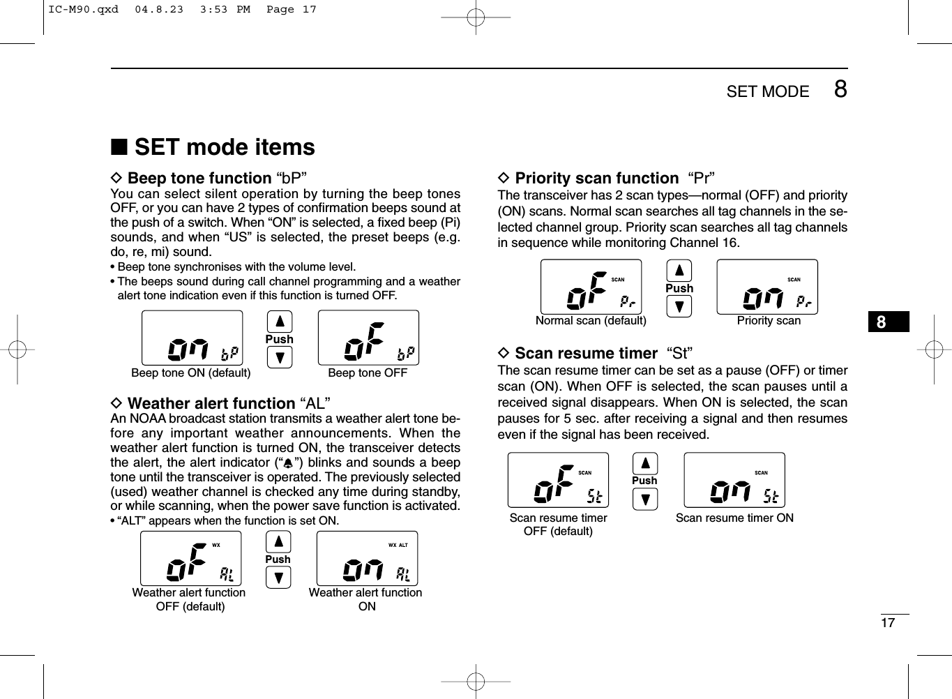
![16SET MODE8■SET mode programmingSET mode is used to change the condition of 17 transceiverfunctions: beep tone function, weather alert function, priorityscan function, scan resume timer, auto scan function, dual/tri-watch function, monitor switch action, automatic backlighting,LCD contrast selection, auto power save function, self checkfunction, battery voltage indicator, signal strength indicator,squelch sensitivity, scrambler code, VOX gain and VOXdelay.DSET mode operationqTurn power OFF.wWhile pushing [SQL•MONI], turn power ON to enter theSET mode.• “bp” (Beep tone function setting) appears.ePush [SQL•MONI] or [SQL•MONI] and [Y]/[Z] to select thedesired item, if necessary.rPush [Y]/[Z] to select the desired condition of the item.tTo exit the SET mode, push [16•9].DSET MODE ITEMS The displays show the default settings, and the selected item is displayed in the dotted circle. VOX delay VOX gain: Push: Push andStarting item Push and Scrambler code Squelch sensitivity Signal strength meter Battery voltage Self check Power save LCD contrast Backlighting Dual/Tri-watch Monitor switch Auto scan Scan resume timer Priority scan Weather alert Beep toneIC-M90.qxd 04.8.23 3:53 PM Page 16](https://usermanual.wiki/ICOM-orporated/279501/User-Guide-474596-Page-22.png)
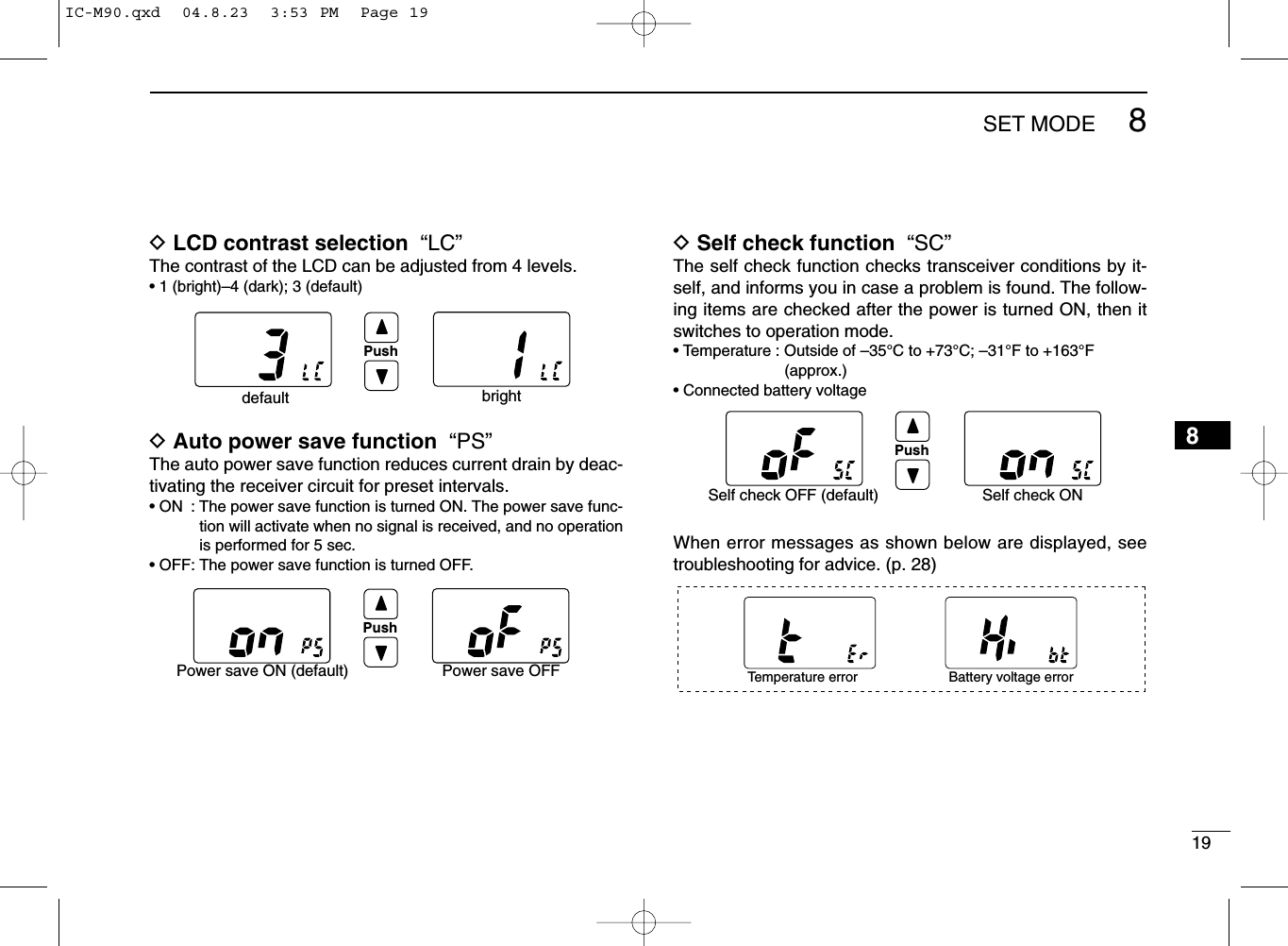
![188SET MODEDAuto scan function “AS”The Auto scan function starts the desired scan automaticallywhen no signal is received, and no operation is performed for30 sec.DDual/Tri-watch function “dt”This item selects dual or tri-watch as desired. See p. 14 fordetails.DMonitor switch action “Sq”The monitor switch action cuts off the squelch function tem-porarily. This switch action contains PUSH (Pu) or HOLD (Ho)settings as shown below.• Pu (PUSH): After pushing [SQL•MONI] for 1 sec., the squelch opensand emits audio. The squelch is held open while con-tinuously pushing and holding [SQL]. (default)• Ho (HOLD): After pushing [SQL•MONI] for 1 sec., the squelch opensand emits audio even [SQL•MONI] is released. To closethe squelch, push any switch.DBacklighting function “bL”This function is convenient for nighttime operation. The back-lighting brightness can be adjusted from OFF, 1 (dark)–3(bright); 3 (default). Select 1–3 to turn this function ON.• The automatic backlighting turns the backlighting ON when anyswitch except for [PTT] is pushed.• The backlighting is automatically turned OFF after 5 sec. of inactivity.PushAuto scan OFF (default) Auto scan ONPushDualwatch function (default) Tri-watch functionPushPush setting (default) Hold settingPushBacklighting ON (default) Backlighting OFFIC-M90.qxd 04.8.23 3:53 PM Page 18](https://usermanual.wiki/ICOM-orporated/279501/User-Guide-474596-Page-24.png)
![2711OPTIONAL SPEAKER-MICROPHONE1011■HM-125 DescriptionsNEVER immerse the connector in water. If the connector be-comes wet, be sure to dry BEFORE attaching it to the trans-ceiver.NOTE: The microphone is located at the top of thespeaker-microphone, as shown in the diagram above. Tomaximize the readability of your transmitted signal (voice),hold the microphone approx. 2.5 cm (1 inch) from yourmouth, and speak in a normal voice level.■AttachmentInsert the connector of the speaker-microphone into [SP MIC]connector on the transceiver and rotate (screw) the connectorcover as shown in the diagram below. IMPORTANT: KEEP [SP MIC] connector cap attached(transceiver) when the speaker-microphone is not in use.Water will not get into the transceiver even if the cover isnot attached, however, the terminals (pins) will becomerusty, or the transceiver will function abnormally if the con-nector has become wet.Alligator type clipTo attach the speaker-mic.to your shirt or collar, etc.PTT switchTransmits during push.Receives during release.MicrophoneSpeakerSet the triangle mark to the front side.CAUTION: Attach the speaker-microphone’sconnector securely to prevent accidentaldropping, or water intrusion in the connector.Detaching:Pull up the capin the directionof the arrow todetach it.Attaching:Attach the capin the directionof the arrowcompletely.IC-M90.qxd 04.8.23 3:54 PM Page 27](https://usermanual.wiki/ICOM-orporated/279501/User-Guide-474596-Page-33.png)
![28TROUBLESHOOTING12The transceiver doesnot turn ON.No sound from thespeaker.Transmitting is impos-sible, or high powercan not be selected.The displayed channelcannot be changed.Scan does not start.No beeps.Self check error.(Temperature)Self check error.(Battery voltage)•The battery is exhausted.•Bad connection to the battery pack.•Squelch level is too deep.•Volume level is too low.•Speaker has been exposed to water.• Water has entered to [SP MIC] connector.•Some channels are for low power or re-ceive only.•The battery is exhausted.•The battery over charged.•The output power is set to low.•Lock function is activated.•“TAG” channels are not programmed.•Beep tones are turned OFF.•The temperature is outside of –35°C to+73°C; –31°F to +163°F (approx)•The connected battery pack’s voltage ismore than 11 V.•Recharge the battery pack.•Check the connection to the transceiver.•Set squelch to the threshold point.•Rotate [VOL] to set a suitable level.•Drain water from the speaker.• Dry [SP MIC] connector.•Change channels.•Recharge the battery pack.•Verify the battery voltage is correct.•Push [Hi/Lo•] to select high power.•Push [Hi/Lo•] for 1 sec. to cancel thefunction.•Set the desired channels as “TAG” channels.•Set the beep tones to ON (Fix Beep/UserBeep) on the SET mode.•Leave the transceiver at room temperaturefor a while. Turn the power ON to check if theinternal temperature has returned to normal.•Verify the battery voltage is correct.p. 22p. 3p. 9p. 9——pgs. 8,9, 29p. 23—p. 9p. 10p. 13p. 17——PROBLEM POSSIBLE CAUSE SOLUTION REF.IC-M90.qxd 04.8.23 3:54 PM Page 28](https://usermanual.wiki/ICOM-orporated/279501/User-Guide-474596-Page-34.png)
![30SPECIFICATIONS14GENERAL• Frequency coverage[Marine] TX : 156.025–157.425 MHzRX 156.050–163.275 MHz[LMR] TX/RX 146.000–174.000 MHz• Mode[Marine] : 16K0G3E (Wide)[LMR] : 16K0F3E (Wide)/8K50F3E (Narrow)• Channel spacing : 25 kHz (Wide)12.5 kHz (Narrow; LMR only)• Number of programmable ch. : 100 channels• Power supply requirement : BP-223, BP-224 or BP-225 only• Current drain (at 7.5 V DC) : TX High (5 W) 1.6 A typicalTX Mid. (3 W) 1.2 A typicalTX Low (1 W) 0.7 A typicalPower save 20 mA typical• Useable temperature range[Marine] : –20°C to +60°C; –4°F to +140°F[LMR] : –30°C to +60°C; –22°F to +140°F• Frequency stability : ±5 ppm(–30°C to +60°C;–22°F to +140°F)• Antenna impedance : 50 Ω• Dimensions : 65(W) ×145(H) ×44(D) mm(Projections not included) 29⁄16(W) ×523⁄32(H) ×13⁄4(D) inch• Weight (with BP-225) : Approx. 410 g (14.46 oz)TRANSMITTER• Output power (at 7.5 V DC) : 5 W (Hi), 3 W (Middle) and 1 W (Low)• Modulation system : Variable reactance frequencymodulation• Microphone impedance : 2 kΩ• Max. frequency deviation[Marine] : ±5 kHz[LMR] : ±5 kHz (Wide), ±2.5 kHz (Narrow)• Adjacent channel power[Marine] : 70 dB[LMR] : 70 dB (Wide), 60 dB (Narrow)• Spurious emissions : Less than –70 dBc typicalRECEIVER• Receive system : Double-conversion superheterodyne• Sensitivity (12 dB SINAD) : 0.25 µV typical• Squelch sensitivity : Less than 0.35 µV typical(at threshold)• Intermodulation rejection ratio : 70 dB typical• Spurious response rejection ratio : 70 dB typical• Adjacent channel selectivity (Typical)[Marine] : 70 dB[LMR] : 70 dB (Wide), 60 dB (Narrow)• Audio output power : 0.35 W typical at 10% distor-tion with an 8 ΩloadAll stated specifications are subject to change without notice orobligation.IC-M90.qxd 04.8.23 3:54 PM Page 30](https://usermanual.wiki/ICOM-orporated/279501/User-Guide-474596-Page-36.png)
![Channel 16 (p. 7) CHANNEL SELECTION (pgs. 7, 8, 10) Weather channel (p. 8)OPERATION GUIDEiM90 IN CASE OF EMERGENCYDISTRESS CALL PROCEDURE USING CHANNEL 161.2.3.4.5.6.MAYDAY MAYDAY MAYDAY.THIS IS (name of vessel)Your call sign or other indi-cation of the vessel.LOCATED AT (your position)The nature of the distress and assistance required.Any other information which might facilitate the rescue. Channel 9/Call channel (p. 7) Call channel programming (p. 10)Push [16 9] to select the call chan-nel.Push [16 9] for 3 sec. (until long beep changes to 2 short beeps)Push [Y]/[Z] to select the desired channel.Push [16 9] to program the dis-played channel as the call channel.qwer USA/International/Canadian/LAND channels (p. 8)Push PushPushPushfor 1 sec.for 1 sec.3115QUICK REFERENCEImportant operating instructions are summed up in this and the following pagefor your simple reference.By cutting along the line and folding on the dotted line, it will become a cardsized operating guide which can easily be carried in a card case or wallet,etc.q Cut w Fold e Complete<CUT HERE>IC-M90.qxd 04.8.23 3:54 PM Page 31](https://usermanual.wiki/ICOM-orporated/279501/User-Guide-474596-Page-37.png)
![TAG CHANNELS (p. 13)q wPush [Y]/[Z] to select the desired channel.Push [Y]/[Z] for 1 sec. to change the TAG setting ON and OFF. WEATHER ALERT (pgs. 8, 17)q wTurn the weather alert item in the SET mode ON (p. 17).Select WX channel; or start scan-ning. SET MODE (pgs. 16 21)q werWhile pushing [SQL MONI], turn power ON.Push [SQL MONI] again to select an item.Push [Y]/[Z] to select the desired condition.Push [16 9] to return to regular op-erating mode.Refer to pgs. 15 20 for setmode item. DUALWATCH/TRI-WATCH (p. 14)Select dual or tri-watch in the SET mode (p. 18).Push [Y]/[Z] to select the desired channel.Push [SCAN D/T] for 1 sec. to start dualwatch or tri-watch (depending on SET mode).To cancel dualwatch/tri-watch, push [SCAN D/T] again.qwer LOCK FUNCTION (p. 10)Push [Hi/Lo ] for 1 sec. to turn the lock function ON and OFF. SQUELCH LEVEL (p. 11)Push [SQL MONI], then adjust the squelch level with [Y]/[Z].Select monitor switch action in SET mode (p. 18).Push [SQL MONI] for 1sec. to ac-tive the monitor function.qw MONITOR FUNCTION (p. 10) SCAN (pgs. 12, 13)Push [SCAN DIAL] to start/stop scanning.32IC-M90.qxd 04.8.23 3:54 PM Page 32](https://usermanual.wiki/ICOM-orporated/279501/User-Guide-474596-Page-38.png)