ICOM orporated 279501 IC-M90 VHF Marine Transceiver User Manual IC M90 instruction manual
ICOM Incorporated IC-M90 VHF Marine Transceiver IC M90 instruction manual
User Manual
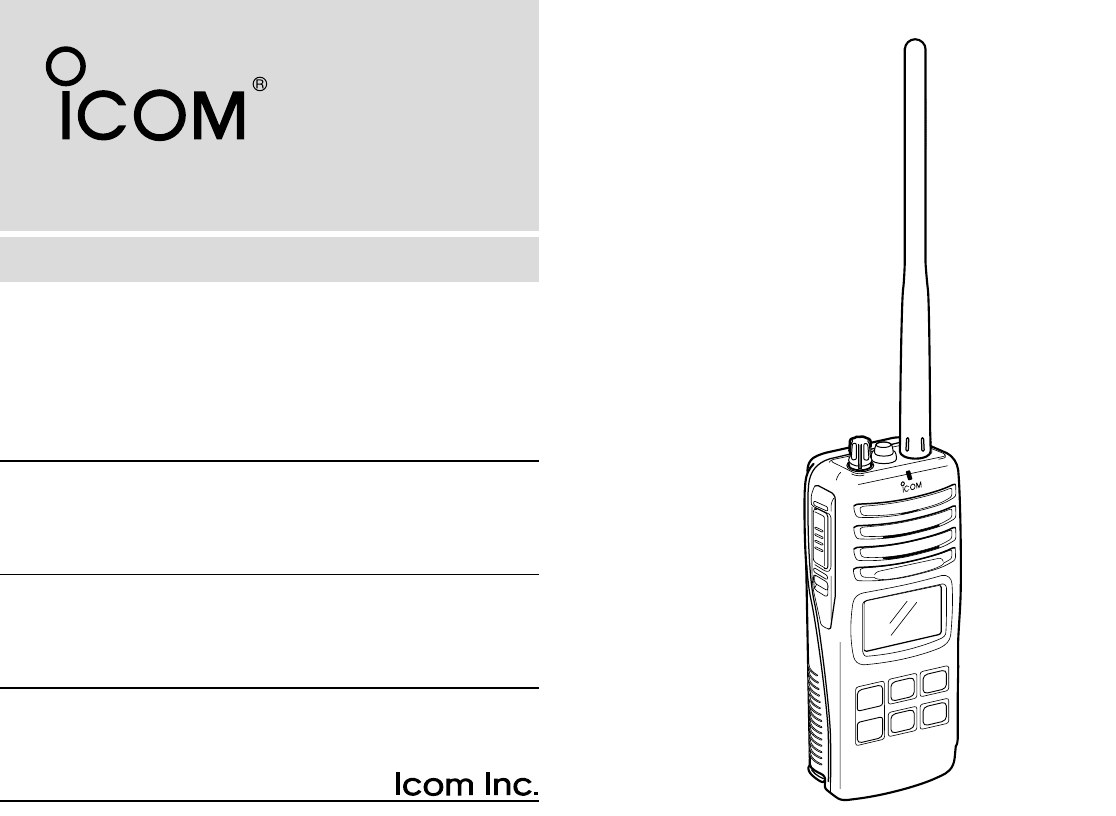
INSTRUCTION MANUAL
iM90
VHF MARINE TRANSCEIVER
This device complies with Part 15 of the FCC
Rules. Operation is subject to the condition that
this device does not cause harmful interference.
IC-M90.qxd 04.8.23 3:53 PM Page A

i
SAFETY TRAINING INFORMATION
Your Icom radio generates RF electromagnetic energy during
transmit mode. This radio is designed for and classified as
“Occupational Use Only”, meaning it must be used only dur-
ing the course of employment by individuals aware of the haz-
ards, and the ways to minimize such hazards. This radio is
NOT intended for use by the “General Population” in an un-
controlled environment.
This radio has been evaluated for compliance at the distance of 2.5 cm with
the FCC RF exposure limits for “Occupational Use Only”. In addition, your Icom
radio complies with the following Standards and Guidelines with regard to RF
energy and electromagnetic energy levels and evaluation of such levels for ex-
posure to humans:
• FCC OET Bulletin 65 Edition 97-01 Supplement C, Evaluating Compliance
with FCC Guidelines for Human Exposure to Radio Frequency Electro-
magnetic Fields.
• American National Standards Institute (C95.1-1992), IEEE Standard for
Safety Levels with Respect to Human Exposure to Radio Frequency Elec-
tromagnetic Fields, 3 kHz to 300 GHz.
• American National Standards Institute (C95.3-1992), IEEE Recommended
Practice for the Measurement of Potentially Hazardous Electromagnetic
Fields– RF and Microwave.
• The following accessories are authorized for use with this product. Use of
accessories other than those specified may result in RF exposure levels
exceeding the FCC requirements for wireless RF exposure.; Belt Clip (MB-
86/103), Rechargeable Ni-Cd Battery Pack (BP-225) and Alkaline Battery
Case (BP-223).
To ensure that your expose to RF electromagnetic en-
ergy is within the FCC allowable limits for occupational
use, always adhere to the following guidelines:
CAUTION
WARNING
• DO NOT operate the radio without a proper antenna attached, as this may
damaged the radio and may also cause you to exceed FCC RF exposure
limits. A proper antenna is the antenna supplied with this radio by the man-
ufacturer or antenna specifically authorized by the manufacturer for use
with this radio.
• DO NOT transmit for more than 50% of total radio use time (“50% duty
cycle”). Transmitting more than 50% of the time can cause FCC RF expo-
sure compliance requirements to be exceeded. The radio is transmitting
when the “TX indicator” lights red. You can cause the radio to transmit by
pressing the “PTT” switch.
• ALWAYS keep the antenna at least 2.5 cm (1 inch) away from the body
when transmitting and only use the Icom belt-clips which are listed on
page 33 when attaching the radio to your belt, etc., to ensure FCC RF ex-
posure compliance requirements are not exceeded. To provide the recipi-
ents of your transmission the best sound quality, hold the antenna at least
5 cm (2 inches) from your mouth, and slightly off to one side.
The information listed above provides the user with the information needed to
make him or her aware of RF exposure, and what to do to assure that this radio
operates with the FCC RF exposure limits of this radio.
Electromagnetic Interference/Compatibility
During transmissions, your Icom radio generates RF energy that can possibly
cause interference with other devices or systems. To avoid such interference,
turn off the radio in areas where signs are posted to do so. DO NOT operate
the transmitter in areas that are sensitive to electromagnetic radiation such as
hospitals, aircraft, and blasting sites.
Occupational/Controlled Use
The radio transmitter is used in situations in which persons are exposed as
consequence of their employment provided those persons are fully aware of
the potential for exposure and can exercise control over their exposure.
IC-M90.qxd 04.8.23 3:53 PM Page i
ii
IN CASE OF EMERGENCY
If your vessel requires assistance, contact other vessels and
the Coast Guard by sending a distress call on Channel 16.
❍USING CHANNEL 16
DISTRESS CALL PROCEDURE
1. “MAYDAY MAYDAY MAYDAY.”
2. “THIS IS ...........................” (name of vessel)
3. Your call sign or other indication of the ves-
sel.
4. “LOCATED AT .....................” (your position)
5. The nature of the distress and assistance re-
quired.
6. Any other information which might facilitate
the rescue.
RECOMMENDATION
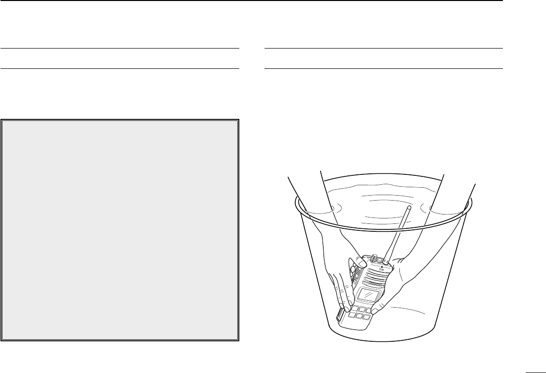
CLEAN THE TRANSCEIVER THOROUGHLY WITH FRESH
WATER after exposure to saltwater, and dry it before opera-
tion. Otherwise, the transceiver’s keys, switches and con-
trollers may become inoperable due to salt crystallization.
MIC
/SP
IC-M90.qxd 04.8.23 3:53 PM Page ii

FOREWORD
Thank you for purchasing this Icom product. The IC-M90 VHF
MARINE TRANSCEIVER is designed and built with Icom’s state
of the art technology and craftsmanship. With proper care this
product should provide you with years of trouble-free operation.
IMPORTANT
READ ALL INSTRUCTIONS carefully and com-
pletely before using the transceiver.
SAVE THIS INSTRUCTION MANUAL—This in-
struction manual contains important operating instructions for
the IC-M90.
EXPLICIT DEFINITIONS
FEATURES
☞Waterproof construction
Built tough to withstand the punishing marine environ-
ment, the IC-M90 meets JIS waterproof specification
grade 7 while using BP-223 (option) or BP-225.
☞Dualwatch and tri-watch functions
Convenient functions which allow you to monitor the dis-
tress channel (Ch 16) while receiving a channel of your
choice—dualwatch; or monitor the distress channel and
another channel while receiving a channel of your
choice—tri-watch.
☞Large, easy-to-read LCD
With dimensions of 19(H) ×35(W) mm; 3⁄4(H) ×13⁄8(W) inch,
the IC-M90’s function display is easy to read and shows op-
erating conditions at a glance. Backlighting and contrast
can be adjusted to suit your preferences.
☞Simple operation
6 large buttons on the front panel provide user-friendly op-
eration. The independent volume and channel buttons are
located on the front panel for convenient one-hand opera-
tion.
iii
WORD DEFINITION
RWARNING
CAUTION
NOTE
Personal injury, fire hazard or electric shock
may occur.
If disregarded, inconvenience only. No risk
of personal injury, fire or electric shock.
Equipment damage may occur.
IC-M90.qxd 04.8.23 3:53 PM Page iii

iv
PRECAUTION
RWARNING! NEVER connect the transceiver to an
AC outlet. This may pose a fire hazard or result in an electric
shock.
RWARNING! NEVER hold the transceiver so that the
antenna is closer than 2.5 cm (1 inch) from exposed parts of
the body, especially the face or eyes, while transmitting. The
transceiver will perform best if the microphone is 5 to 10 cm
(2 to 4 inches) away from the lips and the transceiver is verti-
cal.
NEVER connect the transceiver to a power source other
than the BP-225 or BP-223. Such a connection will ruin the
transceiver.
AVOID using or placing the transceiver in direct sunlight or
in areas with temperatures below –20°C (–4°F) or above
+60°C (+140°F): MARINE, –30°C (–22°F) or above +60°C
(+140°F): LMR.
KEEP the transceiver out of the reach of children.
KEEP the transceiver at least 0.9 meters (3.0 ft) away from
your vessel’s magnetic navigation compass.
MAKE SURE the flexible antenna and battery pack are
securely attached to the transceiver, and that the antenna and
battery pack are dry before attachment. Exposing the inside
of the transceiver to water will result in serious damage to the
transceiver.
BE CAREFUL! The IC-M90 employs waterproof con-
struction, which corresponds to JIS waterproof specification,
Grade 7 (1 m; 3 ft depth for 30 min.). However, once the
transceiver has been dropped, waterproofing cannot be guar-
anteed due to the fact that the transceiver may be cracked,
or the waterproof seal damaged, etc.
For U.S.A. only
CAUTION: Changes or modifications to this device, not
expressly approved by Icom Inc., could void your authority to
operate this device under FCC regulations.
Icom, Icom Inc. and the logo are registered trademarks of Icom Incor-
porated (Japan) in the United States, the United Kingdom, Germany, France,
Spain, Russia and/or other countries.
IC-M90.qxd 04.8.23 3:53 PM Page iv

v
SAFETY TRAINING INFORMATION ............................................... i
IN CASE OF EMERGENCY ........................................................... ii
RECOMMENDATION ...................................................................... ii
FOREWORD .................................................................................. iii
IMPORTANT ................................................................................... iii
EXPLICIT DEFINITIONS ................................................................ iii
FEATURES ..................................................................................... iii
PRECAUTION ................................................................................ iv
TABLE OF CONTENTS .................................................................. v
1 OPERATING RULES ................................................................. 1
2 SUPPLIED ACCESSORIES AND ATTACHMENTS ............... 2–3
■Supplied accessories............................................................... 2
■Attachments............................................................................. 2
3 PANEL DESCRIPTION .......................................................... 4–6
■Front, top and side panels ....................................................... 4
■Function display ...................................................................... 5
4 BASIC OPERATION ............................................................. 7–11
■Channel selection ................................................................... 7
■Receiving and transmitting ...................................................... 9
■Call channel programming .................................................... 10
■Lock function ......................................................................... 10
■Signal strength indicator function .......................................... 10
■Monitor function .................................................................... 10
■Adjusting the squelch level .................................................... 11
■Automatic backlighting .......................................................... 11
■Voice scrambler operation ..................................................... 11
5 SCAN OPERATION ........................................................... 12–13
■Scan types ............................................................................ 12
■Setting tag channels ............................................................. 13
■Starting a scan ...................................................................... 13
6 DUALWATCH/TRI-WATCH ...................................................... 14
■Description ............................................................................ 14
■Operation .............................................................................. 14
7 LAND CHANNEL OPERATION ............................................... 15
■LAND channel group ............................................................. 15
■CTCSS and DTCS display .................................................... 15
■VOX function ......................................................................... 15
8 SET MODE ......................................................................... 16–21
■SET mode programming ....................................................... 16
■SET mode items ................................................................... 17
9 BATTERY CHARGING ....................................................... 22–25
■Battery charging .................................................................... 22
■Battery cautions .................................................................... 22
■Optional battery case ............................................................ 23
■Optional battery chargers ...................................................... 24
10 OPTIONAL SWIVEL BELT CLIP ............................................. 26
■MB-86 contents ..................................................................... 26
■Attachment ............................................................................ 26
■Detachment ........................................................................... 26
11 OPTIONAL SPEAKER-MICROPHONE .................................. 27
■Descriptions .......................................................................... 27
■Attachment ............................................................................ 27
12 TROUBLESHOOTING ............................................................. 28
13 VHF MARINE CHANNEL LIST ............................................... 29
14 SPECIFICATIONS ................................................................... 30
15 QUICK REFERENCE .............................................................. 31
16 OPTIONS ................................................................................. 33
TABLE OF CONTENTS
IC-M90.qxd 04.8.23 3:53 PM Page v

1
1
OPERATING RULES
DPriorities
• Read all rules and regulations pertaining to priorities and
keep an up-to-date copy handy. Safety and distress calls
take priority over all others.
• You must monitor Channel 16 when you are not operating
on another channel.
• False or fraudulent distress calls are prohibited under law.
DPrivacy
• Information overheard but not intended for you cannot law-
fully be used in any way.
• Indecent or profane language is prohibited.
DRadio licenses
(1) SHIP STATION LICENSE
When your craft is equipped with a VHF FM transceiver, you
must have a current radio station license before using the
transceiver. It is unlawful to operate a ship station which is not
licensed.
Inquire through your dealer or the appropriate government
agency for a Ship-Radiotelephone license. This license in-
cludes the call sign which is your craft’s identification for radio
purposes.
(2) OPERATOR’S LICENSE
A restricted Radiotelephone Operator Permit is the license
most often held by small vessel radio operators when a radio
is not required for safety purposes.
The Restricted Radiotelephone Operator Permit must be
posted near the transceiver or be kept with the operator. Only
a licensed radio operator may operate a transceiver.
However, non-licensed individuals may talk over a transceiver
if a licensed operator starts, supervises, ends the call and
makes the necessary log entries.
A current copy of the applicable government rules and regu-
lations is only required to be on hand for vessels in which a
radio telephone is compulsory. However, even if you are not
required to have these on hand it is your responsibility to be
thoroughly acquainted with all pertinent rules and regulations.
NOTE: Even though the IC-M90 is capable of operation
on VHF marine channels 3, 21, 23, 61, 64, 81, 82 and 83,
according to FCC regulations these simplex channels can-
not be lawfully used by the general occupational in USA
waters.
1
IC-M90.qxd 04.8.23 3:53 PM Page 1
2
SUPPLIED ACCESSORIES AND ATTACHMENTS
2
■Supplied accessories
The following accessories are supplied: Qty.
• Handstrap . . . . . . . . . . . . . . . . . . . . . . . . . . . . . . . . . . . . . 1
• Belt clip (MB-103) . . . . . . . . . . . . . . . . . . . . . . . . . . . . . . . 1
• Ni-Cd battery pack (BP-225) . . . . . . . . . . . . . . . . . . . . . . 1
• Battery charger (BC-158) . . . . . . . . . . . . . . . . . . . . . . . . . 1
• Screws for the BC-158 (M3.5 ×20) . . . . . . . . . . . . . . . . . 2
• AC adapter (BC-147A) . . . . . . . . . . . . . . . . . . . . . . . . . . . 1
• Flexible antenna (FA-S59V) . . . . . . . . . . . . . . . . . . . . . . . 1
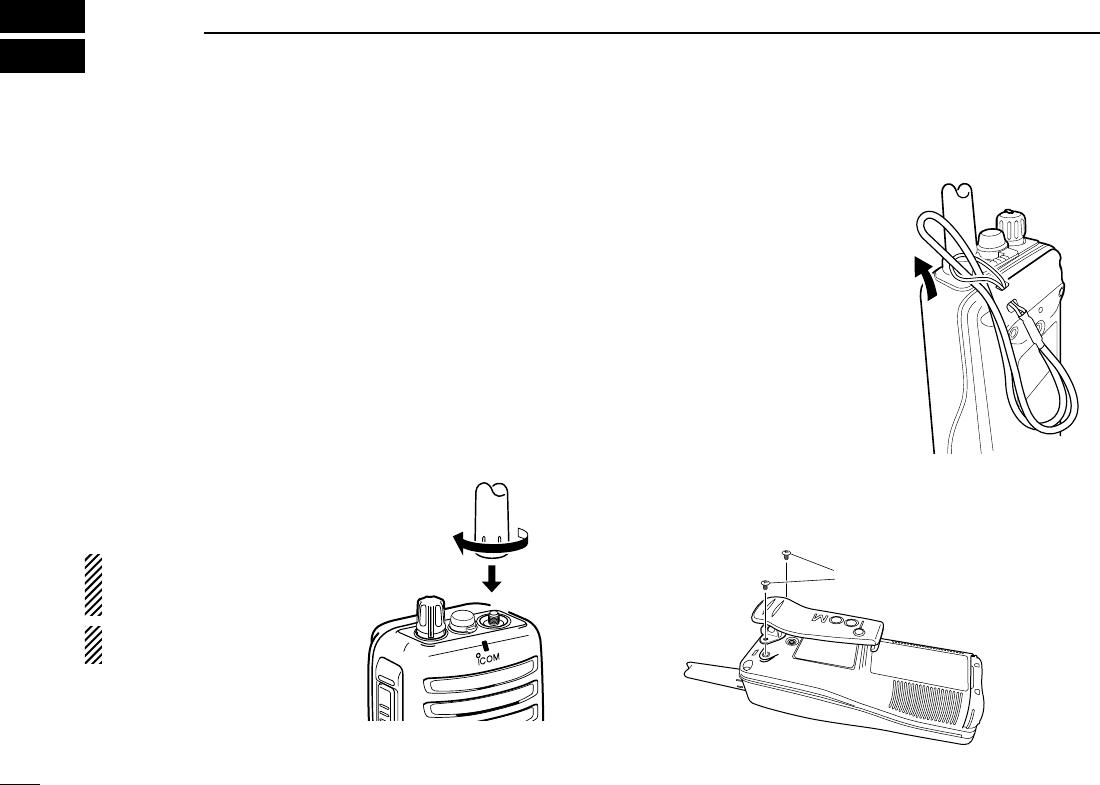
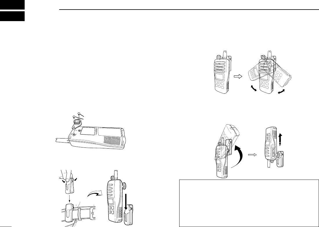
■Attachments
DFlexible antenna
Connect the supplied flexible an-
tenna to the antenna connector.
CAUTION: Transmitting without
an antenna may damage the
transceiver.
NEVER HOLD by the antenna
when carrying the transceiver.
DHandstrap
Pass the handstrap through the
loop on the top of the transceiver
as illustrated at right. Facilitates
carrying.
DBelt clip
Attach the belt clip to the transceiver as illustrated below.
Supplied screws
MIC
/SP
IC-M90.qxd 04.8.23 3:53 PM Page 2
3
2
SUPPLIED ACCESSORIES AND ATTACHMENTS
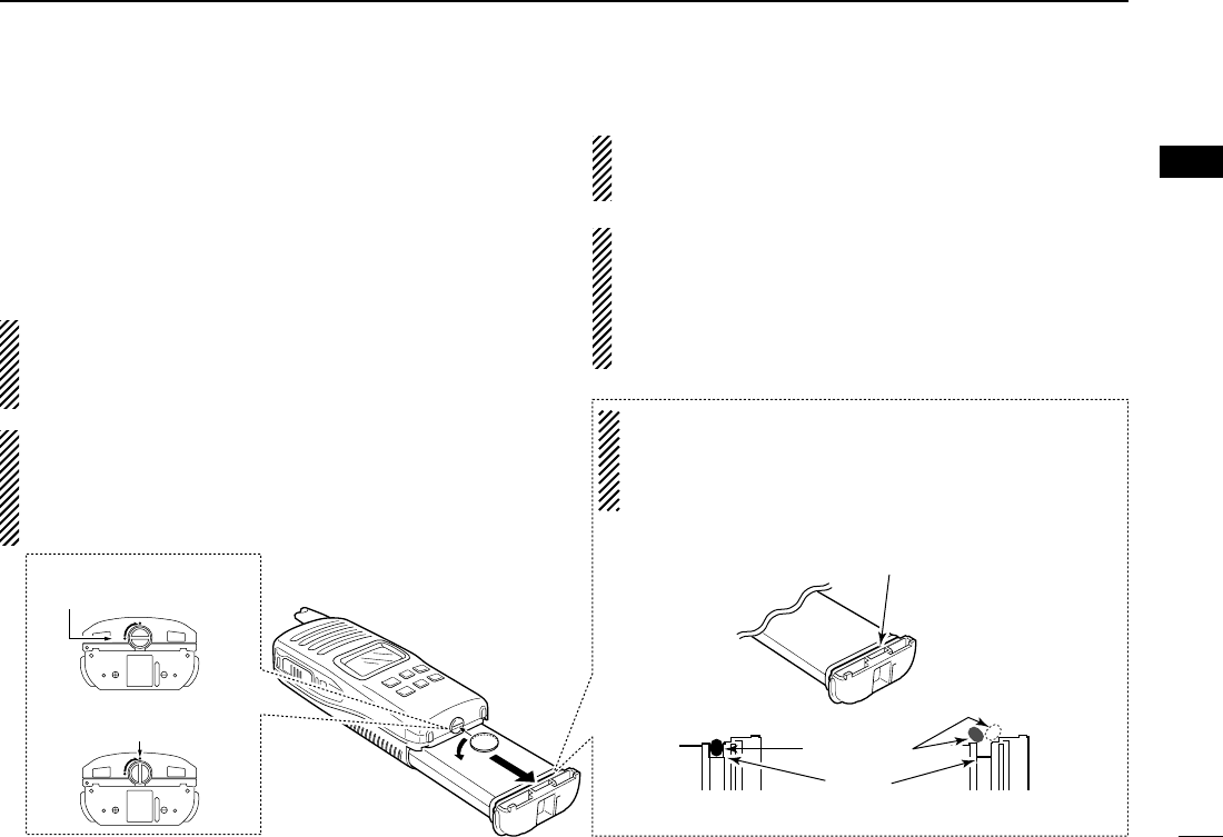
ïBattery pack
To remove the battery pack:
Turn the screw counterclockwise, then pull the battery pack
in the direction of the arrow as shown below.
To attach the battery pack:
Insert the battery pack in the IC-M90 completely, then turn the
screw clockwise.
NEVER remove or insert the battery pack when the trans-
ceiver is wet or soiled. This may result water or dust get-
ting into the transceiver/battery pack and may result in the
transceiver being damaged.
NOTE: When removing or attaching the battery pack, use
a coin or flat-blade screwdriver to loosen or tighten the bot-
tom screw.
CAUTION!:
When attaching or removing a battery pack, make sure the
rubber seal is set in the groove of the battery pack cor-
rectly. If the seal is not neatly in the groove it may be dam-
aged when attaching the battery pack.
If the seal is damaged, waterproofing is not guaranteed.
OPEN
LOCK
Screw position
when removing battery
Screw position
when attaching battery
OPEN
LOCK
Make sure both the rubber seal (purple) is set to the groove
correctly and dust or else does not adhere to it.
Battery pack Battery pack
Rubber seal
Groove
Correct position Incorrect position
NOTE:
When attaching a battery pack, make sure dust or else does
not adhere to the rubber seal. If dust or else is on the seal
when attaching a battery pack, the water resistant may be
reduced.
2
NOTE: When the lock screw does not easily (feels tight),
check to ensure the battery pack is sufficiently inserted to
the transceiver. DO NOT bang or cause high impact to
the battery pack, as this may damage the battery pack/or
the transceiver.
IC-M90.qxd 04.8.23 3:53 PM Page 3
4
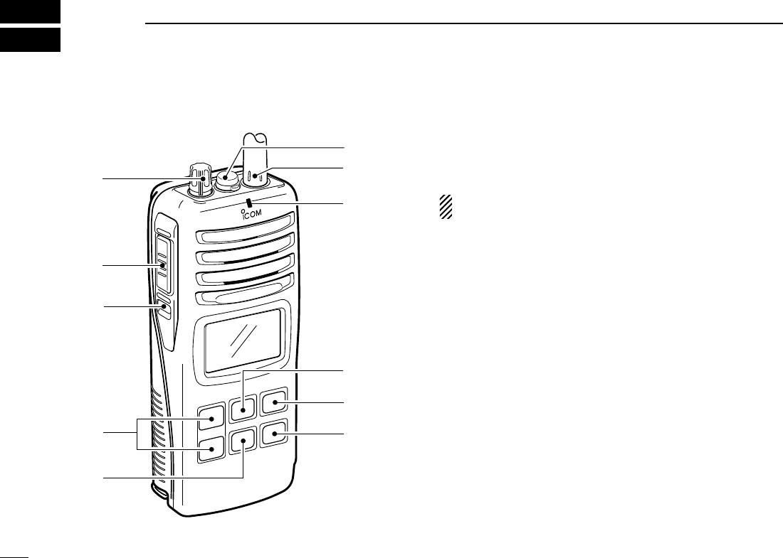
PANEL DESCRIPTION
3
■Front, top and side panels
qVOLUME CONTROL [VOL]
Turns power ON and adjusts the audio level.
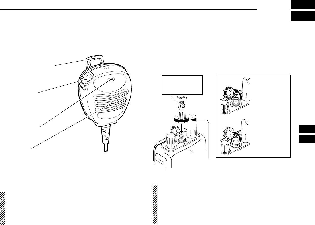
wMICROPHONE CONNECTOR [SP MIC]
Connects the optional external microphone.
NOTE: Attach the [SP MIC] cap when the optional
speaker-microphone is not used.
eANTENNA CONNECTOR
Connects the supplied antenna.
rTRANSMIT/RECEIVE INDICATOR
Lights green while receiving a signal or when the squelch
is open; lights red while transmitting.
tCHANNEL/WEATHER CHANNEL SWITCH
[CH/WX•U/I/C/L]
•Selects and toggles the regular channels and weather
channel when pushed. (p. 8)
•Selects one of 4 regular channels in sequence when
pushed for 1 sec. (pgs. 8, 15)
- U.S.A., International, Canadian and Land channels are
available.
•Push to return to the condition before selecting the chan-
nel when the priority channel or the call channel is se-
lected.
ySCAN SWITCH [SCAN•DUAL]
•Starts and stops normal or priority scan when pushed.
(pgs. 12, 13)
•Enters watch mode when pushed for 1 sec. (p. 14)
MIC
/SP
qe
r
y
t
w
i
u
o
!1
!0
IC-M90.qxd 04.8.23 3:53 PM Page 4
5
3
PANEL DESCRIPTION
uTRANSMIT POWER/LOCK SWITCH [Hi/Lo•]
•Selects high, middle or low power when pushed. (p. 9)
•Toggles the lock function ON/OFF when pushed for
1 sec. (p. 10)
iCHANNEL 16 SWITCH [16•9]
•Selects Channel 16 when pushed. (p. 7)
• Selects call channel when pushed for 1 sec. (p. 7)
• Enters call channel write mode when the call channel is
selected and this switch is pushed for 3 sec. (p. 10)
oCHANNEL UP/DOWN SWITCHES [YY]/[ZZ]
•Selects an operating channel. (pgs. 7–9)
•Selects the SET mode condition of the item. (p. 16)
•Selects the SET mode item when pushed with [SQL].
(p. 16)
• Checks tag channels or changes scanning direction dur-
ing scan. (p. 13)
!0 SQUELCH SWITCH [SQL•MONI]
•Push this switch, then adjust the squelch level with
[YY]/[ZZ]. (p. 11)
• Manually opens the squelch for monitoring the channel
while pushed and held. (p. 10)
•While pushing this switch, turn power ON to enter the set
mode. (p. 16)
!1 PTT SWITCH [PTT]
Push and hold to transmit; release to receive.
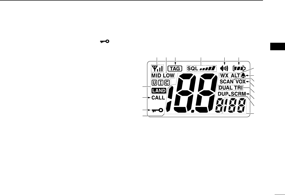
■Function display
qSIGNAL STRENGTH INDICATOR (pgs. 10, 20)
Shows the relative signal strength while receiving signals.
wTRANSMIT POWER INDICATOR
• “LOW” appears when low power is selected.
• “MID” appears when middle power is selected.
• No indication appears when high power is selected.
eTAG CHANNEL INDICATOR (p. 13)
Appears when tag channel is selected.
rSQUELCH LEVEL INDICATOR (p. 11)
Show the squelch level.
q r t yw e
!4
!6
!5
u
i
o
!0
!1
!2
!3
!8
!7
3
IC-M90.qxd 04.8.23 3:53 PM Page 5
6
3PANEL DESCRIPTION
tMONITOR INDICATOR (p. 10)
Appears when the monitor function is activated.
yBATTERY INDICATOR
Indicates remaining battery power.
uWEATHER CHANNEL/WEATHER ALERT INDICATORS
(p. 8)
• “WX” appears when the weather channel group is
selected.
• “WX ALT” appears while the weather alert function is
activated.
iBELL INDICATOR
Blinks when an alert tone is received.
oSCAN INDICATOR (p. 13)
“SCAN” blinks during scan.
!0 VOX INDICATOR (p. 15)
“VOX” appears during the VOX function is used.
!1 DUALWATCH/TRI-WATCH INDICATORS (p. 14)
“DUAL” blinks during dualwatch; “TRI” blinks during tri-
watch.
!2 SCRAMBLER INDICATOR
Appears when the optional voice scrambler is activated.
(pgs. 11, 20)
!3 DUPLEX INDICATOR
Appears when a duplex channel is selected.
!4 SUB CHANNEL READOUT
• Indicates Channel 16 during priority scan or dualwatch.
(p. 14)
• Indicates the SET mode item while on the SET mode.
(p. 16)
!5 CHANNEL NUMBER READOUT
• Indicates the selected operating channel number.
• In SET mode, indicates the selected condition.
!6 LOCK INDICATOR
Appears while the lock function is activated.
!7 CALL CHANNEL INDICATOR
Appears when the call channel is selected.
!8 CHANNEL GROUP INDICATOR
“U” appears when U.S.A.; “I” appears when Interna-
tional; “C” appears when Canadian; “” appears when
LAND channel group is selected.
Indication
Full Middle Charging
required No battery
Battery level
blinks when the battery is exhaustion.
blinks when the battery over charged.
IC-M90.qxd 04.8.23 3:53 PM Page 6
7
4
BASIC OPERATION
3
4
■Channel selection
IMPORTANT!: Prior to using the transceiver for the first
time, the battery pack must be fully charged for optimum
life and operation. To avoid damage to the transceiver, turn
the power OFF while charging.
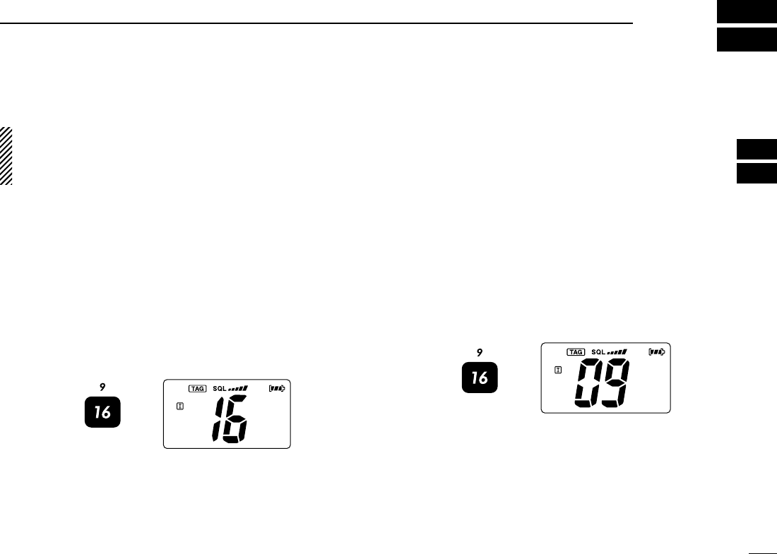
DChannel 16
Channel 16 (Distress channel) is used for establishing initial
contact with another station and for emergency communica-
tions. Channel 16 is automatically monitored during both
dualwatch and tri-watch. While standing by, you must monitor
Channel 16.
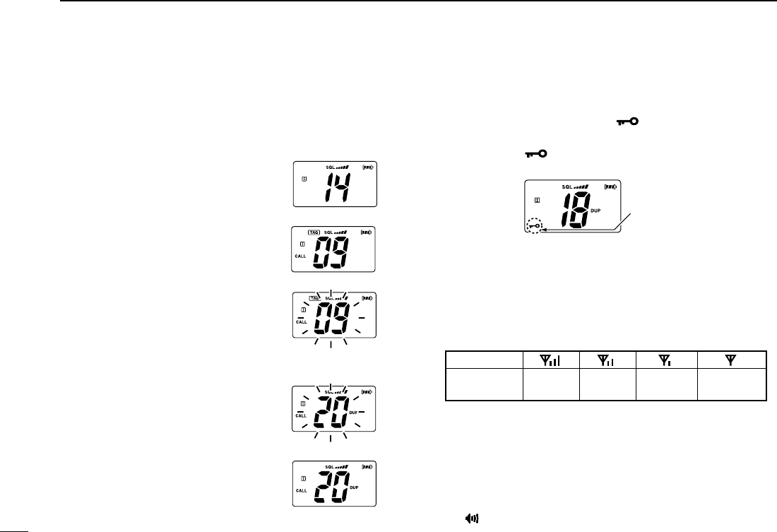
qPush [16•9] to select Channel 16.
wPush [CH/WX•U/I/C/L] to return to the condition before se-
lecting Channel 16, or push [Y]/[Z] to select the operating
channel.
DChannel 9 (Call channel)
Channel 9 is the leisure-use call channel. Each regular
channel group has separate call channels. In addition, the call
channel is monitored during tri-watch. The call channels can
be re-programmed (p. 10) and are used to store your most
often used channels in each channel group for quick recall.
qPush [16•9] to select the call channel.
•“CALL” and the call channel number appear.
•Call channel can be re-programmed. See the “Call channel
programming” on p. 10 for details.
wPush [CH/WX•U/I/C/L] to return to the condition before se-
lecting Channel 9 (call channel), or push [Y]/[Z] to select
the operating channel.
Push
Push
IC-M90.qxd 04.8.23 3:53 PM Page 7
Push for 1 sec.
U.S.A. channels
International channels Canadian channels*
8
4BASIC OPERATION
D
U.S.A., International and Canadian channels
The IC-M90 has 57 U.S.A., 57 International and 61 Canadian
channels. These channel groups may be specified for the op-
erating area.
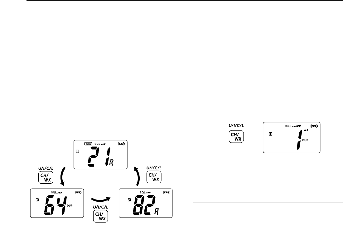
qPush [CH/WX•U/I/C/L] to select the regular channel.
•If the weather channel appears, push [CH/WX•U/I/C/L] again.
wPush [Y]/[Z] to select a channel.
•“DUP” appears for duplex channels.
eTo change the channel group, push [CH/WX•U/I/C/L] for 1
sec.
•U.S.A., International and Canadian channels can be selected in
sequence. Depending on the setting, LAND channel can be se-
lected. See the “LAND CHANNEL OPERATION” on p. 15 for de-
tails.
DWeather channels
The IC-M90 are 10 weather channels. They are used for
monitoring weather channels from the NOAA (National
Oceanographic and Atmospheric Administration) broadcasts
(reception of weather channels possible in U.S.A. only).
qPush [CH/WX•U/I/C/L] to select the weather channel group.
wPush [Y]/[Z] to select a weather channel.
ePush [CH/WX•U/I/C/L] to return to the condition before se-
lecting the weather channel group.
✔
CONVENIENT!
The IC-M90 can detect a weather alert tone on the
selected weather channel while in another channel (when the
power save function is turned ON) or during scanning. See
the “SET mode items” on p. 17 for details.
Push
IC-M90.qxd 04.8.23 3:53 PM Page 8
9
4
BASIC OPERATION
4
■Receiving and transmitting
qRotate [VOL] clockwise to turn power ON.
wUseSet the volume and squelch level.
➥Push [SQL•MONI], and push [√] to open the squelch.
➥Push [SQL•MONI] to stop “SQL” indicator blinking, then
rotate [VOL] to set the volume level.
➥Push [SQL•MONI], and push [∫]/[√] to set the squelch
level.
ePush [Y]/[Z] to select the desired channel.
- When receiving a signal, the [TRANSMIT/RECEIVE] indicator
lights green while audio is emitted from the speaker.
- Further adjustment of [VOL] may be necessary at this point.
rPush [Hi/Lo•] to select the output power if necessary.
- “LOW” appears when low power is selected; “MID” appears
when middle power is selected; no indication when high power is
selected.
- Choose low power to conserve battery power, choose high
power for longer distance communications.
- Some channels are for low power only.
tPush and hold [PTT] to transmit, then speak into the
microphone.
- The [TRANSMIT/RECEIVE] indicator lights red while
transmitting.
- Channel 70 cannot be used for transmission.
yRelease [PTT] to receive.
IMPORTANT: To maximize the readability of your trans-
mitted signal, pause a few sec. after pushing [PTT], hold
the microphone 5 to 10 cm (2 to 4 inches) from your mouth
and speak into the microphone at a normal voice level.
NOTE: The transceiver has a power save function to con-
serve the battery power. The power save function activates
automatically when no signal is received for 5 sec.
To prevent accidental prolonged transmission, etc., the IC-
M90 has a time-out timer function. This timer cuts a trans-
mission OFF after 5 min. of continuous transmission.
CAUTION: Transmitting without an antenna may
damage the transceiver.
MIC
/SP
q Power ON
e Set volume
Speaker
y Push to transmit
u Release to receive
r Set channel
w Set the squelch level
w Set the squelch level
e Set volume
Microphone
t Set output power
IC-M90.qxd 04.8.23 3:53 PM Page 9
10
4BASIC OPERATION
■Call channel programming
The call channel switch is used to select Channel 9 by de-
fault, however, you can program your most often-used chan-
nel in each channel group for quick recall.
qPush [CH/WX•U/I/C/L] for 1 sec. to
several times to select the desired
channel group (USA, INT, CAN) to
be programmed.
wPush [16•9] for 1 sec. to select the
call channel.
•“CALL” and call channel number
appear.
ePush [16•9] again for 3 sec. (until a
long beep changes to 2 short beeps)
to enter call channel programming
condition.
•Call channel number to be programmed
flashes.
rPush [Y]/[Z] to select the desired
channel.
tPush [16•9] to program the displayed
channel as the call channel.
•The call channel number stop
flashing.
■Lock function
This function electronically locks all switches (except for
[PTT], [SQL•MONI] and [Hi/Lo•]) to prevent accidental
channel changes and function access.
➥Push [Hi/Lo•] for 1 sec. to turn the lock function ON
and OFF.
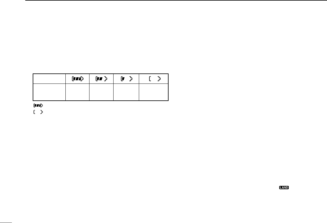
■Signal strength indicator
function
The received signal strength level is indicated by number of
bars as below.
This indicator can be hided in set mode (p. 20) if desired.
■Monitor function
The monitor function releases the noise squelch mute to
check the volume level. See p. 18 for details of the monitor
switch action.
➥Push [SQL•MONI] for 1 sec. to activate the monitor function.
•“ ” appears and audio is emitted.
Indication
Strong Middle Weak No signal or
very weak
Signal
strength
Appears while the lock
function is used.
IC-M90.qxd 04.8.23 3:53 PM Page 10
11
4
BASIC OPERATION
4
■Adjusting the squelch level
The IC-M90 has a squelch level adjustment, even though there
is no control knob for it. In order to receive signals properly, as
well as for the scan to function effectively, the squelch must be
adjusted to the proper level.
qPush [SQL•MONI], then adjust the squelch level with [Y]/[Z].
- “SQL” indicator starts blinking.
- There are 11 squelch levels to choose from: OP is completely
open; 10 is tight squelch; 1 is loose squelch level.
- When no switch is pushed for 5 sec., the transceiver returns to
normal condition.
wPush [SQL•MONI] again to return to normal condition.
■Backlighting function
This function is convenient for nighttime operation. The back-
lighting brightness can be adjusted in the SET mode. (p. 18)
➥Push any switch except for [PTT] to turn the backlighting
ON.
•The backlighting is automatically turned OFF after 5 sec. of
inactivity.
■Voice scrambler operation
DActivating the scrambler
The voice scrambler provides private communications. In
order to receive or send scrambled transmissions, you must
activate the scrambler function first.
q
Select an operating
channel except Channel
16, 70 or weather chan-
nels.
wWhile pushing and
holding [SQL•MONI],
push [SCAN•DUAL].
•“SCRM” appears.
eTo turn the scrambler
function OFF, repeat
step w.
•“SCRM” disappears.
DProgramming scramble codes
There are 32 codes (1 to 32) available for programming. Set
the code on the SET mode. In order to understand each other,
all transceivers in your group must have the same scramble
code, as well as the same scrambler unit. See p.
20
for “Scram-
bler code” setting details.
Appears when the voice
scrambler function is in use.
Blinks during the squelch
level adjutment.
Indicates the
squelch level.
Push
IC-M90.qxd 04.8.23 3:53 PM Page 11
12
SCAN OPERATION
5
■Scan types
Scanning is an efficient way to locate signals quickly over a
wide frequency range. The transceiver has priority scan and
normal scan.
In addition, the “Weather alert” and “Auto scan” functions are
available for standby convenience. These functions can be
activated simultaneously, depending on the settings on the
SET mode. (pgs. 17, 18)
Set the tag channels (scanned channel) before scanning.
Clear the tag channels which inconveniently stop scanning,
such as digital communications.
Choose priority or normal scan on the SET mode. (p. 17)
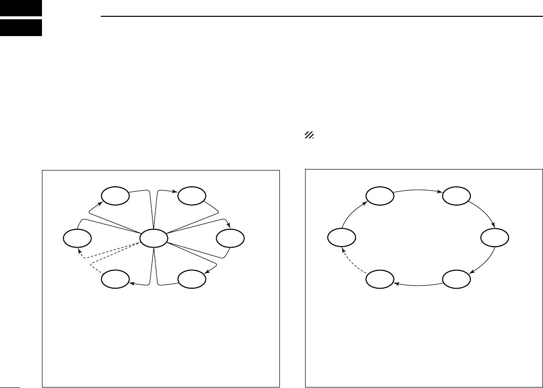
PRIORITY SCAN
Priority scan searches through all tag channels in sequence
while monitoring Channel 16. When a signal is detected on
Channel 16, scan pauses until the signal disappears; when
a signal is detected on a channel other than Channel 16,
scan becomes dualwatch until the signal disappears.
WX*
CH 01
CH 16
CH 02
CH 05 CH 04
CH 03
* Previously selected weather channel
when weather alert function is ON
NORMAL SCAN
Normal scan, like priority scan, searches through all tag
channels in sequence. However, unlike priority scan, Chan-
nel 16 is not checked unless Channel 16 is set as a tag
channel.
CH 01 CH 02
WX*
CH 05 CH 04
CH 03
* Previously selected weather channel
when weather alert function is ON.
IC-M90.qxd 04.8.23 3:53 PM Page 12
13
5
SCAN OPERATION
5
■Setting tag channels
For more efficient scanning, add desired channels as tag
channels or clear the tag for unwanted channels.
Non-tag channels will be skipped during scanning.
qSelect the desired channel to set as a tag channel.
wPush both [Y] and [Z] for 1 sec. to set the displayed chan-
nel as a tag channel.
•“ ” appears in the function display.
eTo cancel the tag channel setting, push both [Y] and [Z]
for 1 sec.
•“ ” disappears.
✔Clearing all tag channels in the selected channel group
While pushing and holding both [Y] and [Z], turn power ON
to clear all tag channels in the channel group.
■Starting a scan
Set the weather alert function, priority scan function, scan re-
sume timer and auto scan function in advance, using the SET
mode. (pgs. 17, 18)
qSelect the desired channel group (USA, CAN, INT) by
pushing [CH/WX•U/I/C/L] for 1 sec., if desired.
•When the weather alert function is in use, select the desired
weather channel with [CH/WX•U/I/C/L] and [Y]/[Z].
wPush [SCAN•DUAL]to start priority or normal scan.
•“SCAN” blinks in the function display.
•“16” appears on the sub channel readout during priority scan.
•When a signal is received, scan pauses until the signal disap-
pears or resumes after pausing 5 sec. according to scan resume
timer setting. (Channel 16 is still monitored during priority scan.)
•Push [Y]/[Z] to check the scanning tag channels, change the
scanning direction or resume the scan manually.
eTo stop the scan, push [SCAN•DUAL].
•“SCAN” disappears.
•Pushing [PTT], [16•9] or [CH/WX•U/I/C/L] also stops the scan.
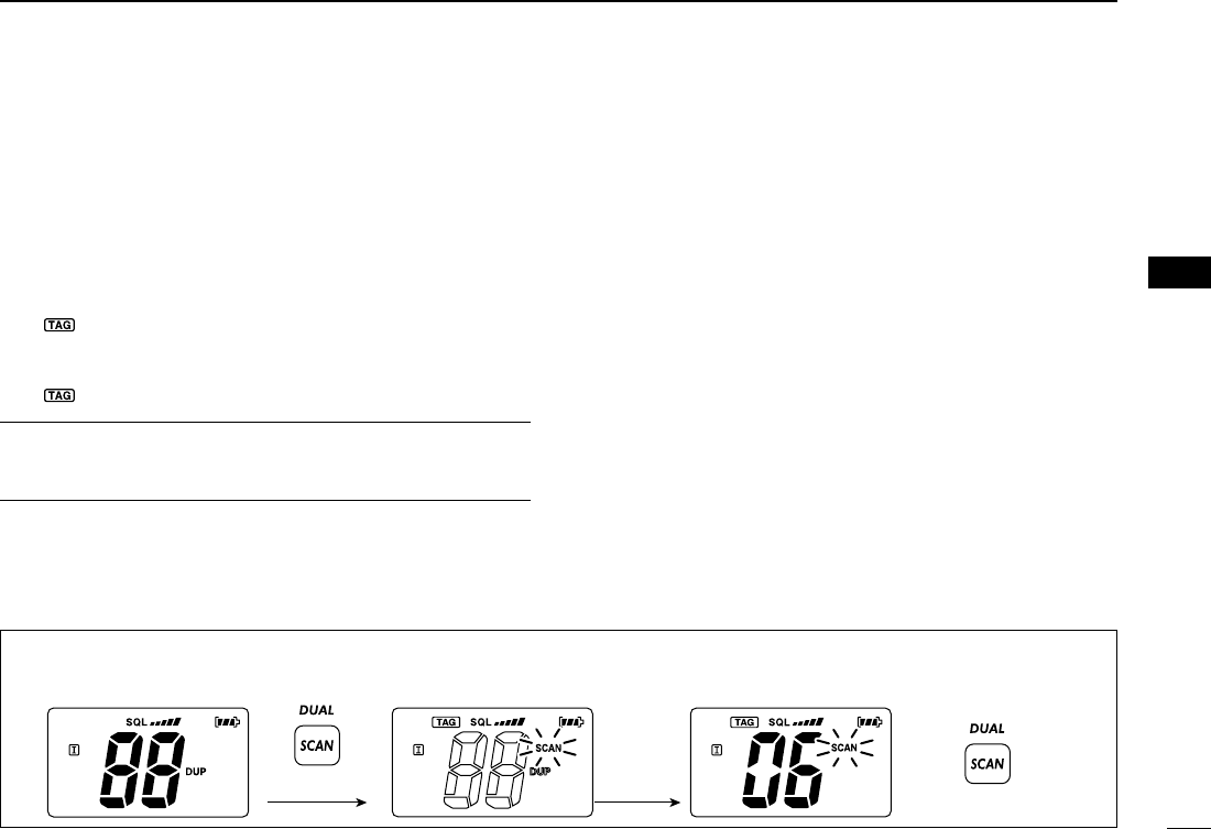
[Example]: Starting a normal scan.
Scan starts.
Push
to stop the scan
Receiving a signal
and audio is emitted.
for 1 sec.
Push
IC-M90.qxd 04.8.23 3:53 PM Page 13
14
DUALWATCH/TRI-WATCH
6
■Description
Dualwatch monitors Channel 16 while you are receiving
another channel; tri-watch monitors Channel 16 and the call
channel while receiving another channel.
■Operation
qSelect the desired operating channel.
wPush [SCAN•DUAL]for 1 sec. to start dualwatch or tri-watch
(depending on the SET mode setting).
•“DUAL” blinks during dualwatch; “TRI” blinks during tri-watch.
•A beep tone sounds when a signal is received on Channel 16.
•Tri-watch becomes dualwatch when receiving a signal on the call
channel.
eTo cancel dualwatch/tri-watch, push [SCAN•DUAL]again.
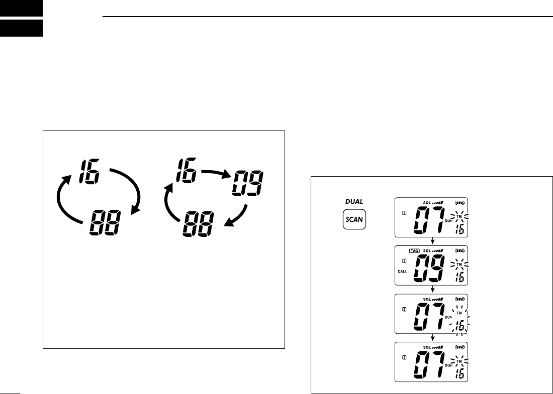
DUALWATCH/TRI-WATCH SIMULATION
•If a signal is received on Channel 16, dualwatch/tri-watch
pauses on Channel 16 until the signal disappears.
•If a signal is received on the call channel during tri-watch,
tri-watch becomes dualwatch until the signal disappears.
•To transmit on the selected channel during dualwatch/tri-
watch, push and hold [PTT].
Dualwatch Tri-watch
Call channel
[Example]: Operating tri-watch on INT channel 07.
Push
for 1 sec.
Signal is received
on the call channel.
Signal ireceived on
Channel 16 takes
priority.
Tri-watch resumes
after the signal
disappears.
Tri-watch starts.
IC-M90.qxd 04.8.23 3:53 PM Page 14
15
7
LAND CHANNEL OPERATION
6
7
■LAND channel group
A max. of 100 programmable LAND mobile channels (allo-
cated 146.000 to 174.000 MHz) can be programmed into the
LAND channel group for simple communication with LMR
transceivers in the VHF band.
Moreover, any of the marine channels in the USA, INT and
CAN channel groups can be programmed.
The default setting of the LAND channel group is the same
as that of the INT channel group. Ask your local Icom dealer
for the LAND channel group setting and LMR frequency pro-
gramming details.
qPush [CH/WX•U/I/C/L] to select a regular channel.
•If weather channel appears, push [CH/WX•U/I/C/L] again.
wTo change the channel group, push [CH/WX•U/I/C/L] for
1 sec. several times.
•“ ” appears when LAND channel group is selected.
ePush [Y]/[Z] to select a channel.
•“DUP” appears for duplex channels.
NOTE: The default settings (e.g. call channel program-
ming) of the LAND channel group are same as the U.S.A.,
International and Canadian channels. Refer to the appro-
priate pages for details.
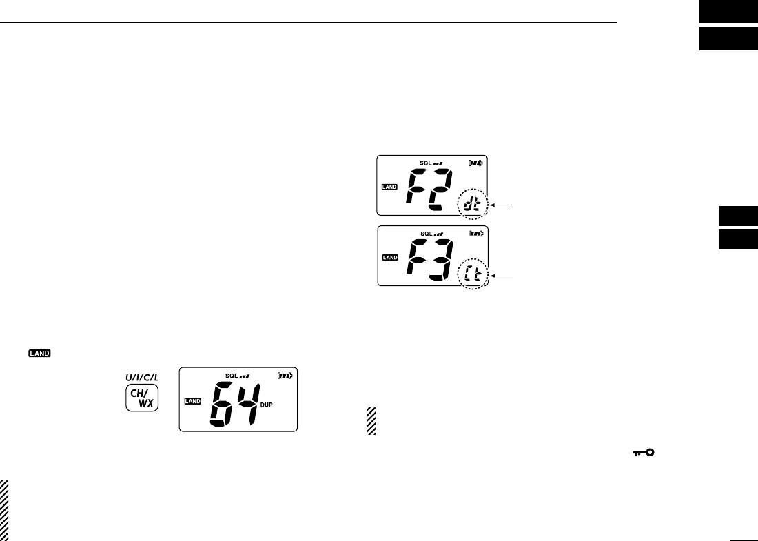
■CTCSS and DTCS display
When DTCS or CTCSS is set, the display shows the indica-
tions as below.
■VOX function
The VOX function (voice operated transmission) starts trans-
mission without pushing [PTT] when you speak into micro-
phone; then automatically returns to receive when you stop
speaking (hands-free operation becomes possible).
NOTE: An optional headset and optional headset adapter
is required for the VOX operation.
➥Push and hold [SQL•MONI], then push [Hi/Lo•] to turn
the VOX function ON/OFF while connecting the headset
and optional headset adapter to [SP MIC] connector.
• “VOX” appears on the LCD while the VOX function turns ON.
• The “VOX gain” and “VOX delay” can be set on the SET mode.
(p. 21)
Push for 1 sec.
Appears when DTCS is set.
Appears when CTCSS is set.
IC-M90.qxd 04.8.23 3:53 PM Page 15

16
SET MODE
8
■SET mode programming
SET mode is used to change the condition of 17 transceiver
functions: beep tone function, weather alert function, priority
scan function, scan resume timer, auto scan function, dual/tri-
watch function, monitor switch action, automatic backlighting,
LCD contrast selection, auto power save function, self check
function, battery voltage indicator, signal strength indicator,
squelch sensitivity, scrambler code, VOX gain and VOX
delay.
DSET mode operation
qTurn power OFF.
wWhile pushing [SQL•MONI], turn power ON to enter the
SET mode.
• “bp” (Beep tone function setting) appears.
ePush [SQL•MONI] or [SQL•MONI] and [Y]/[Z] to select the
desired item, if necessary.
rPush [Y]/[Z] to select the desired condition of the item.
tTo exit the SET mode, push [16•9].
DSET MODE ITEMS The displays show the default settings, and the selected item is displayed in the dotted circle.
VOX delay VOX gain
: Push
: Push and
Starting item
Push and
Scrambler code
Squelch sensitivity
Signal strength
meter Battery voltage Self check Power save LCD contrast Backlighting
Dual/Tri-watch
Monitor switch
Auto scan Scan resume timer Priority scan Weather alert Beep tone
IC-M90.qxd 04.8.23 3:53 PM Page 16

17
8
SET MODE
8
■SET mode items
DBeep tone function “bP”
You can select silent operation by turning the beep tones
OFF, or you can have 2 types of confirmation beeps sound at
the push of a switch. When “ON” is selected, a fixed beep (Pi)
sounds, and when “US” is selected, the preset beeps (e.g.
do, re, mi) sound.
• Beep tone synchronises with the volume level.
• The beeps sound during call channel programming and a weather
alert tone indication even if this function is turned OFF.
DWeather alert function “AL”
An NOAA broadcast station transmits a weather alert tone be-
fore any important weather announcements. When the
weather alert function is turned ON, the transceiver detects
the alert, the alert indicator (“”) blinks and sounds a beep
tone until the transceiver is operated. The previously selected
(used) weather channel is checked any time during standby,
or while scanning, when the power save function is activated.
•“ALT” appears when the function is set ON.
DPriority scan function “Pr”
The transceiver has 2 scan types—normal (OFF) and priority
(ON) scans. Normal scan searches all tag channels in the se-
lected channel group. Priority scan searches all tag channels
in sequence while monitoring Channel 16.
DScan resume timer “St”
The scan resume timer can be set as a pause (OFF) or timer
scan (ON). When OFF is selected, the scan pauses until a
received signal disappears. When ON is selected, the scan
pauses for 5 sec. after receiving a signal and then resumes
even if the signal has been received.
Scan resume timer
OFF (default)
Scan resume timer ON
Push
Push
Beep tone ON (default) Beep tone OFF
Push
Normal scan (default) Priority scan
Push
Weather alert function
OFF (default)
Weather alert function
ON
IC-M90.qxd 04.8.23 3:53 PM Page 17

18
8SET MODE
DAuto scan function “AS”
The Auto scan function starts the desired scan automatically
when no signal is received, and no operation is performed for
30 sec.
DDual/Tri-watch function “dt”
This item selects dual or tri-watch as desired. See p. 14 for
details.
DMonitor switch action “Sq”
The monitor switch action cuts off the squelch function tem-
porarily. This switch action contains PUSH (Pu) or HOLD (Ho)
settings as shown below.
• Pu (PUSH): After pushing [SQL•MONI] for 1 sec., the squelch opens
and emits audio. The squelch is held open while con-
tinuously pushing and holding [SQL]. (default)
• Ho (HOLD): After pushing [SQL•MONI] for 1 sec., the squelch opens
and emits audio even [SQL•MONI] is released. To close
the squelch, push any switch.
DBacklighting function “bL”
This function is convenient for nighttime operation. The back-
lighting brightness can be adjusted from OFF, 1 (dark)–3
(bright); 3 (default). Select 1–3 to turn this function ON.
•
The automatic backlighting turns the backlighting ON when any
switch except for [PTT] is pushed.
•
The backlighting is automatically turned OFF after 5 sec. of inactivity.
Push
Auto scan OFF (default) Auto scan ON
Push
Dualwatch function (default) Tri-watch function
Push
Push setting (default) Hold setting
Push
Backlighting ON (default) Backlighting OFF
IC-M90.qxd 04.8.23 3:53 PM Page 18

19
8
SET MODE
8
DLCD contrast selection “LC”
The contrast of the LCD can be adjusted from 4 levels.
•
1 (bright)–4 (dark); 3 (default)
DAuto power save function “PS”
The auto power save function reduces current drain by deac-
tivating the receiver circuit for preset intervals.
• ON : The power save function is turned ON. The power save func-
tion will activate when no signal is received, and no operation
is performed for 5 sec.
• OFF: The power save function is turned OFF.
DSelf check function “SC”
The self check function checks transceiver conditions by it-
self, and informs you in case a problem is found. The follow-
ing items are checked after the power is turned ON, then it
switches to operation mode.
• Temperature : Outside of –35°C to +73°C; –31°F to +163°F
(approx.)
• Connected battery voltage
When error messages as shown below are displayed, see
troubleshooting for advice. (p. 28)
Push
default bright
Push
Power save ON (default) Power save OFF
Push
Self check OFF (default) Self check ON
Temperature error Battery voltage error
IC-M90.qxd 04.8.23 3:53 PM Page 19

20
8SET MODE
DBattery voltage indicator “bt”
This function contains display or non-display settings of the
voltage of the connected battery pack when the power is ON.
•
The voltage of the connected battery pack is displayed for 2 sec.
after power is turned ON.
DSignal strength indicator “Sl”
The signal strength indicator displays received signal strength
as “S-meter”. This function is convenient to check the signal
strength visually.
•
The strength is displayed at 4 steps.
• The antenna mark and 3 bars appear when receiving strong signals.
• The antenna mark only appears when receiving no signal.
DSquelch sensitivity function “SS”
When this function is turned ON, blocking against noise is im-
proved. Therefore the squelch is not easily affected by noise.
DScrambler code “cd”
There are 32 codes (1 to 32) available for programming. In
order to understand each other, all transceivers in your group
must have the same scrambler code.
Push
Battery voltage
indication OFF (default)
Battery voltage
indication ON
Push
Signal strength indication OFF
(default)
Signal strength indication ON
Push
Squelch sensitivity OFF (default) Squelch sensitivity ON
Push
Scrambler code 1 (default) Scrambler code 32
IC-M90.qxd 04.8.23 3:53 PM Page 20
21
8
SET MODE
8
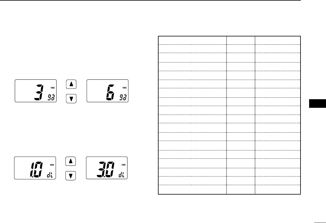
DVOX gain “ga”
Adjusts the VOX gain (from 1 to 6) to turn transmitting auto-
matically when speaking with the optional headset.
• In case of setting to 1, the VOX gain sets to dulling.
• In case of setting to 6, the VOX gain sets to sharpening.
DVOX delay “dL”
Sets the VOX delay timer (0.5 to 3.0 sec. in 0.5 sec. steps)
that keeps on transmitting after you stop speaking.
• In case of setting to 0.5 (0.5 sec.), the VOX delay sets to short.
• In case of setting to 3.0 (3.0 sec.), the VOX delay sets to long.
SET MODE LIST
*default setting
Push
VOX gain 3 (default) VOX gain 6
Push
VOX delay 1.0 (default) VOX delay 3.0
Function Indication Switch
Beep tone function “bP”OFF/ON*/US
Weather alert function “AL”OFF*/ON
Priority scan function “Pr”OFF*/ON
Scan resume timer “St”OFF*/ON
Auto scan function “AS”OFF*/ON
Dual/Tri-watch function “dt”Dual*/Tri
Monitor switch action “Sq”Push*/Hold
Backlighting function “bL”OFF/1/2/3*
LCD contrast selection “LC”1/2/3*/4
Auto power save function “PS”OFF/ON*
Self check function “SC”OFF*/ON
Battery voltage indicator “bt”OFF*/ON
Signal strength indicator “SI”OFF*/ON
Squelch sensitivity “SS”OFF*/ON
Scrambler code “cd”1*/2/· · ·/31/32
VOX gain “ga”1/2/3*/4/5/6
VOX delay “dL”
0.5/1.0*/1.5/2.0/2.5/3.0
IC-M90.qxd 04.8.23 3:53 PM Page 21

22
BATTERY CHARGING
9
■Battery charging
Prior to using the transceiver for the first time, the battery
pack must be fully charged for optimum life and operation.
CAUTION: To avoid damage to the transceiver, turn the
power OFF while charging.
• Recommended temperature range for charging:
+10°C to +40°C (+50°F to +104°F)
• Use the specified chargers (BC-158, BC-119N and
BC-121N). NEVER use another manufacture’s charger.
• Use the supplied AC adapter for the BC-158. NEVER use
another manufacture’s adapters.
NEVER connect DC power to the battery case when in-
stalling Alkaline batteries. Such a connection will damage
the transceiver.
DRecycling information
The product that you have purchased contains a
rechargeable battery. The battery is recyclable.
At the end of its life, under various state and
local laws, it may be illegal to dispose of this bat-
tery into the municipal waste stream. Call 1-800-
822-8837 for battery recycling options in your
area or contact your dealer.
■Battery cautions
CAUTION! NEVER insert battery pack/transceiver
(with the battery pack attached) with wet or soiled into the
charger. This may result in corrosion of the charger terminals
or damage to the charger. The charger is not waterproof and
water can easily get into it.
NEVER incinerate used battery packs. Internal battery gas
may cause an explosion.
NEVER immerse battery pack in water. If the battery pack
becomes wet, be sure to wipe it dry immediately (particularly
the battery terminals BEFORE attaching it to the transceiver.
NEVER short the terminals of the battery pack. Also, cur-
rent may flow into nearby metal objects, such as a necklace,
etc. Therefore, be careful when carrying with, or placing near
metal objects, carrying in handbags, etc.
If your battery pack seem to have no capacity even after
being charged, completely discharge them by leaving the
power ON overnight. Then, fully charge the battery pack
again. If the batteries still do not retain a charge (or very little),
new battery pack must be purchased.
Turn power OFF the transceiver when charging the battery
pack with the transceiver. Otherwise, the battery pack may
not become full-charging or may not charge properly.
IC-M90.qxd 04.8.23 3:53 PM Page 22
23
9
BATTERY CHARGING
9
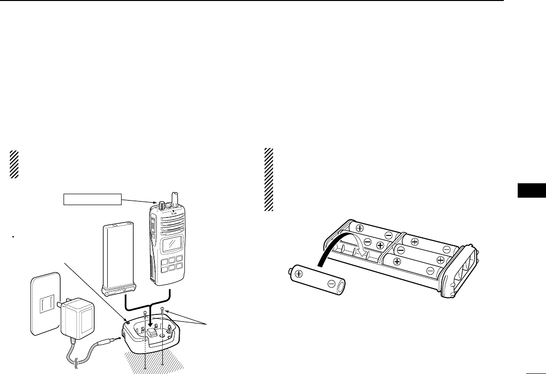
ïCharging connections
qAttach the BC-158 to a flat surface, such as a desk or
cabin, etc., if desired.
wConnect the AC adapter as shown below.
eInsert the battery pack with/without the transceiver into the
charger.
• The charge indicator lights green.
rCharge the battery pack approx. 12 hours, depending on
the remaining power condition.
DO NOT charge BP-225 more than 18 hours. Other-
wise, BP-225 will be damaged. BP-225 must be
charged for 12–18 hours only.
■Optional battery case
When using a battery case attached to the transceiver, install
6 ×AA(R6) size Alkaline batteries as illustrated below.
qRemove the battery case from the transceiver.
wInstall 6 ×AA(R6) size Alkaline batteries.
•Be sure to observe the correct polarity.
CAUTION:
•When installing batteries, make sure they are all the
same brand, type and capacity. Also, do not mix new and
old batteries together.
•Keep battery contacts clean. It’s a good idea to clean bat-
tery terminals once a week.
AC adapter
IC-M90
Turn power OFF
BP-225
BC-158
Supplied
screws
Charge indicator
Lights green when the
BP-225 (with/without
IC-M90) is inserted.
MIC
/SP
IC-M90.qxd 04.8.23 3:53 PM Page 23
24
9BATTERY CHARGING
■Optional battery chargers
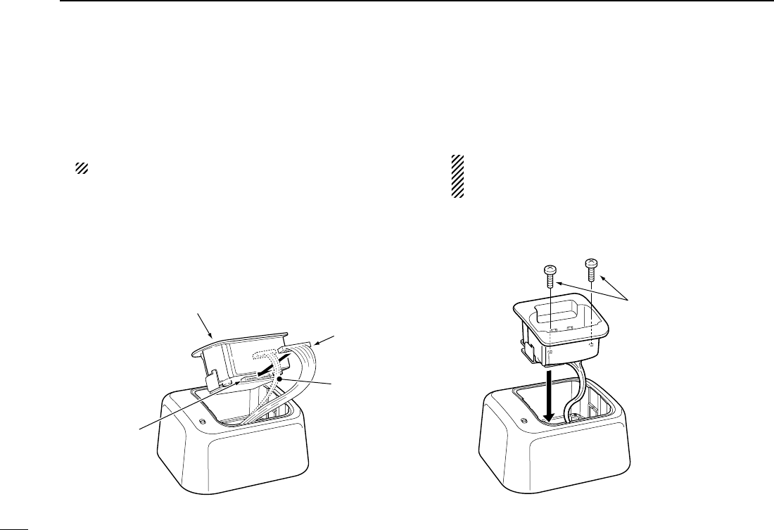
ïAD-109 installation
qConnect the 10-pins connector of the charger to the
AD-109 desktop charger adapter’s plug.
NOTE: The 3-pins connector is not used.
wInstall the adapter into the charger in the direction of the
arrow, then screw supplied 2 screws to fix the charger
adapter with the charger.
NOTE: BE CAREFUL not to catch the unused 3-pins
plug between the charger and the charger
adapter.
Supplied screws
Desktop charger adapter
10-pins connector
Plug
Not used
(3-pins connector)
IC-M90.qxd 04.8.23 3:53 PM Page 24
25
9
BATTERY CHARGING
9
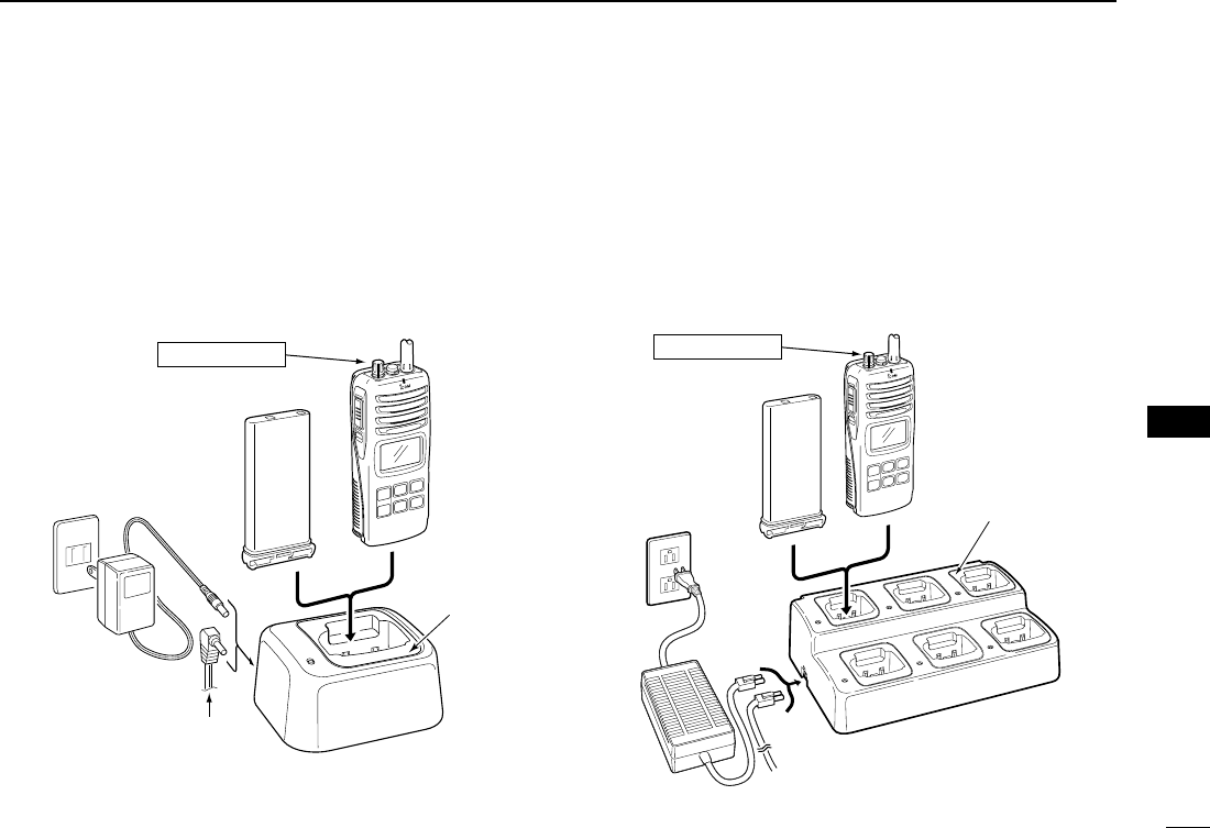
ïRapid charging with the BC-119N+AD-109
The optional BC-119N provides rapid charging of battery
packs. The following are additionally required.
• AD-109 charger adapter
• An AC adapter (BC-147A) or the DC power cable (OPC-
515L/CP-17L).
ïRapid charging with the BC-121N+AD-109
The optional BC-121N allows up to 6 battery packs to be
charged simultaneously. The following are additionally re-
quired.
• Six AD-109 charger adapters
• An AC adapter (BC-124) or the DC power cable (OPC-656)
MIC
/SP
IC-M90
BP-225
AC adapter
(Purchase
separately)
AD-109 charger adapters
are installed in each slot.
DC power cable (OPC-656)
(Connect with the DC power supply;
13.8 V/at least 7 A)
Turn power OFF
AD-109 charger
adapter is installed
in BC-119N.
AC adapter
(Not supplied with
some versions.)
Optional OPC-515L (for 13.8 V power
source) or CP-17L (for 12 V cigarette
lighter socket) can be used instead of
the AC adapter.
IC-M90
BP-225
MIC
/SP
Turn power OFF
IC-M90.qxd 04.8.23 3:53 PM Page 25
26
OPTIONAL SWIVEL BELT CLIP
10
■MB-86 contents
Qty.
Belt clip ………………………………………………………… 1
Base clip ……………………………………………………… 1
Supplied screws ……………………………………………… 2
■Attachment
qScrew the supplied 2 screws to fix the base clip with the
back of the transceiver as illustrated below.
wClip the belt clip to a part of your belt and insert the trans-
ceiver into the belt clip until the base clip fitting into the
groove.
eOnce the transceiver is locked in place, it swivels as illus-
trated below.
■Detachment
➥Turn the transceiver upside down in the direction of the
arrow and pull out from the belt clip.
Supplied screws
PTT
SQL
MONI
RRCAUTION!
HOLD THE TRANSCEIVER TIGHTLY, WHEN HANGING
OR DETACHING THE TRANSCEIVER FROM THE BELT
CLIP.
Otherwise the transceiver may not be attached to the belt
clip or swivelled properly if the transceiver is accidentally
dropped and the base clip is scratched or damaged.
IC-M90.qxd 04.8.23 3:54 PM Page 26
27
11
OPTIONAL SPEAKER-MICROPHONE
10
11
■HM-125 Descriptions
NEVER immerse the connector in water. If the connector be-
comes wet, be sure to dry BEFORE attaching it to the trans-
ceiver.
NOTE: The microphone is located at the top of the
speaker-microphone, as shown in the diagram above. To
maximize the readability of your transmitted signal (voice),
hold the microphone approx. 2.5 cm (1 inch) from your
mouth, and speak in a normal voice level.
■Attachment
Insert the connector of the speaker-microphone into [SP MIC]
connector on the transceiver and rotate (screw) the connector
cover as shown in the diagram below.
IMPORTANT: KEEP [SP MIC] connector cap attached
(transceiver) when the speaker-microphone is not in use.
Water will not get into the transceiver even if the cover is
not attached, however, the terminals (pins) will become
rusty, or the transceiver will function abnormally if the con-
nector has become wet.
Alligator type clip
To attach the speaker-mic.
to your shirt or collar, etc.
PTT switch
Transmits during push.
Receives during release.
Microphone
Speaker
Set the triangle
mark to the front
side.
CAUTION: Attach the speaker-microphone’s
connector securely to prevent accidental
dropping, or water intrusion in the connector.
Detaching:
Pull up the cap
in the direction
of the arrow to
detach it.
Attaching:
Attach the cap
in the direction
of the arrow
completely.
IC-M90.qxd 04.8.23 3:54 PM Page 27

28
TROUBLESHOOTING
12
The transceiver does
not turn ON.
No sound from the
speaker.
Transmitting is impos-
sible, or high power
can not be selected.
The displayed channel
cannot be changed.
Scan does not start.
No beeps.
Self check error.
(Temperature)
Self check error.
(Battery voltage)
•The battery is exhausted.
•Bad connection to the battery pack.
•Squelch level is too deep.
•Volume level is too low.
•Speaker has been exposed to water.
• Water has entered to [SP MIC] connector.
•Some channels are for low power or re-
ceive only.
•The battery is exhausted.
•The battery over charged.
•The output power is set to low.
•Lock function is activated.
•“TAG” channels are not programmed.
•Beep tones are turned OFF.
•The temperature is outside of –35°C to
+73°C; –31°F to +163°F (approx)
•The connected battery pack’s voltage is
more than 11 V.
•Recharge the battery pack.
•Check the connection to the transceiver.
•Set squelch to the threshold point.
•Rotate [VOL] to set a suitable level.
•Drain water from the speaker.
• Dry [SP MIC] connector.
•Change channels.
•Recharge the battery pack.
•Verify the battery voltage is correct.
•Push [Hi/Lo•] to select high power.
•Push [Hi/Lo•] for 1 sec. to cancel the
function.
•Set the desired channels as “TAG” channels.
•Set the beep tones to ON (Fix Beep/User
Beep) on the SET mode.
•Leave the transceiver at room temperature
for a while. Turn the power ON to check if the
internal temperature has returned to normal.
•Verify the battery voltage is correct.
p. 22
p. 3
p. 9
p. 9
—
—
pgs. 8,
9, 29
p. 23
—
p. 9
p. 10
p. 13
p. 17
—
—
PROBLEM POSSIBLE CAUSE SOLUTION REF.
IC-M90.qxd 04.8.23 3:54 PM Page 28

29
13
VHF MARINE CHANNEL LIST
12
13
Channel number
USA CAN
Transmit
Receive
Frequency (MHz)
INT
Channel number Frequency (MHz)
USA CAN
Transmit
ReceiveINT
Channel number Frequency (MHz)
USA CAN
Transmit
ReceiveINT
Channel number Frequency (MHz)
USA CAN
Transmit
ReceiveINT
WX channel Frequency (MHz)
Transmit Receive
01 156.050 160.650
01A 156.050 156.050
02 156.100 160.700
03 156.150 160.750
03A 156.150 156.150
156.200 160.800
04A 156.200 156.200
156.250 160.850
05A 05A 156.250 156.250
06 06 156.300 156.300
156.350 160.950
07A 07A 156.350 156.350
08 08 156.400 156.400
09 09 156.450 156.450
10 10 156.500 156.500
11 11 156.550 156.550
12 12 156.600 156.600
13*13*156.650 156.650
14 14 156.700 156.700
15*15*156.750 156.750
16 16 156.800 156.800
17*17*156.850 156.850
156.900 161.500
18A 18A 156.900 156.900
01
02
03
04
05
06
07
08
09
10
11
12
13
14
15*
16
17
18
156.950 161.550
19A 19A 156.950 156.950
20 20*157.000 161.600
21 157.050 161.650
21A 21A 157.050 157.050
157.100 161.700
22A 22A 157.100 157.100
23 157.150 161.750
23A 157.150 157.150
24 24 157.200 161.800
25 25 157.250 161.850
26 26 157.300 161.900
27 27 157.350 161.950
28 28 157.400 162.000
60 156.025 160.625
156.075 160.675
61A 61A 156.075 156.075
156.125 160.725
62A 156.125 156.125
156.175 160.775
63A 156.175 156.175
64 156.225 160.825
64A 64A 156.225 156.225
19
20
21
22
23
24
25
26
27
28
60
61
62
63
64
20A 157.000 157.000
66A 66A*
156.325 160.925
67*67 156.375 156.375
68 68 156.425 156.425
69 69 156.475 156.475
70 70 156.525
71 71 156.575 156.575
72 72 156.625 156.625
73 73 156.675 156.675
74 74 156.725 156.725
77*77*156.875 156.875
156.925 161.525
78A 78A 156.925 156.925
156.975 161.575
79A 79A 156.975 156.975
157.025 161.625
80A 80A 157.025 157.025
157.075 161.675
81A 81A 157.075 157.075
157.125 161.725
82A 82A 157.125 157.125
66
67
68
69
70
71
72
73
74
77
78
79
80
81
82
156.325 156.32566A
85 85 157.275 161.875
85A 157.275 157.275
86 86 157.325 161.925
86A 157.325 157.325
87 87 157.375 161.975
87A 157.375 157.375
88 88 157.425 162.025
88A 157.425 157.425
85
86
87
88
21b Rx only
Rx only
161.650
25b Rx only 161.850
28b Rx only 162.000
83b Rx only 161.775
4
1 RX only 162.550
2 RX only 162.400
3 RX only 162.475
5 RX only 162.450
6 RX only 162.500
7 RX only 162.525
8 RX only 161.650
9 RX only 161.775
10 RX only 163.275
RX only 162.425
156.275 160.875
65A 65A 156.275 156.275
65
65A 84A
83 157.175 161.775
83A 83A 157.175 157.175
84 84 157.225 161.825
83
84
157.225 157.225
*Low power only.
NOTE: Simplex channels 3, 21, 23, 61, 64, 81, 82 and 83 CANNOT
be lawfully used by the general occupational in USA waters.
IC-M90.qxd 04.8.23 3:54 PM Page 29

30
SPECIFICATIONS
14
GENERAL
• Frequency coverage
[Marine] TX : 156.025–157.425 MHz
RX 156.050–163.275 MHz
[LMR] TX/RX 146.000–174.000 MHz
• Mode
[Marine] : 16K0G3E (Wide)
[LMR] :
16K0F3E (Wide)/8K50F3E (Narrow)
• Channel spacing : 25 kHz (Wide)
12.5 kHz (Narrow; LMR only)
• Number of programmable ch. : 100 channels
• Power supply requirement : BP-223, BP-224 or BP-225 only
• Current drain (at 7.5 V DC) : TX High (5 W) 1.6 A typical
TX Mid. (3 W) 1.2 A typical
TX Low (1 W) 0.7 A typical
Power save 20 mA typical
• Useable temperature range
[Marine] : –20°C to +60°C; –4°F to +140°F
[LMR] :
–30°C to +60°C; –22°F to +140°F
• Frequency stability : ±5 ppm
(–30°C to +60°C;
–22°F to +140°F)
• Antenna impedance : 50 Ω
• Dimensions : 65(W) ×145(H) ×44(D) mm
(Projections not included) 29⁄16(W) ×523⁄32(H) ×13⁄4(D) inch
• Weight (with BP-225) : Approx. 410 g (14.46 oz)
TRANSMITTER
• Output power (at 7.5 V DC) : 5 W (Hi), 3 W (Middle) and
1 W (Low)
• Modulation system : Variable reactance frequency
modulation
• Microphone impedance : 2 kΩ
• Max. frequency deviation
[Marine] : ±5 kHz
[LMR] :
±5 kHz (Wide), ±2.5 kHz (Narrow)
• Adjacent channel power
[Marine] : 70 dB
[LMR] : 70 dB (Wide), 60 dB (Narrow)
• Spurious emissions : Less than –70 dBc typical
RECEIVER
• Receive system : Double-conversion
superheterodyne
• Sensitivity (12 dB SINAD) : 0.25 µV typical
• Squelch sensitivity : Less than 0.35 µV typical
(at threshold)
• Intermodulation rejection ratio : 70 dB typical
• Spurious response rejection ratio : 70 dB typical
• Adjacent channel selectivity (Typical)
[Marine] : 70 dB
[LMR] : 70 dB (Wide), 60 dB (Narrow)
• Audio output power : 0.35 W typical at 10% distor-
tion with an 8 Ωload
All stated specifications are subject to change without notice or
obligation.
IC-M90.qxd 04.8.23 3:54 PM Page 30
Channel 16 (p. 7)
CHANNEL SELECTION (pgs. 7, 8, 10)
Weather channel (p. 8)
OPERATION GUIDE
iM90
IN CASE OF EMERGENCY
DISTRESS CALL PROCEDURE
USING CHANNEL 16
1.
2.
3.
4.
5.
6.
MAYDAY MAYDAY MAYDAY.
THIS IS (name of vessel)
Your call sign or other indi-
cation of the vessel.
LOCATED AT (your position)
The nature of the distress
and assistance required.
Any other information which
might facilitate the rescue.
Channel 9/Call channel (p. 7)
Call channel programming (p. 10)
Push [16 9] to select the call chan-
nel.
Push [16 9] for 3 sec. (until long
beep changes to 2 short beeps)
Push [
Y
]/[
Z
] to select the desired
channel.
Push [16 9] to program the dis-
played channel as the call channel.
q
w
e
r
USA/International/Canadian/LAND
channels (p. 8)
Push Push
Push
Push
for 1 sec.
for 1 sec.
31
15
QUICK REFERENCE
Important operating instructions are summed up in this and the following page
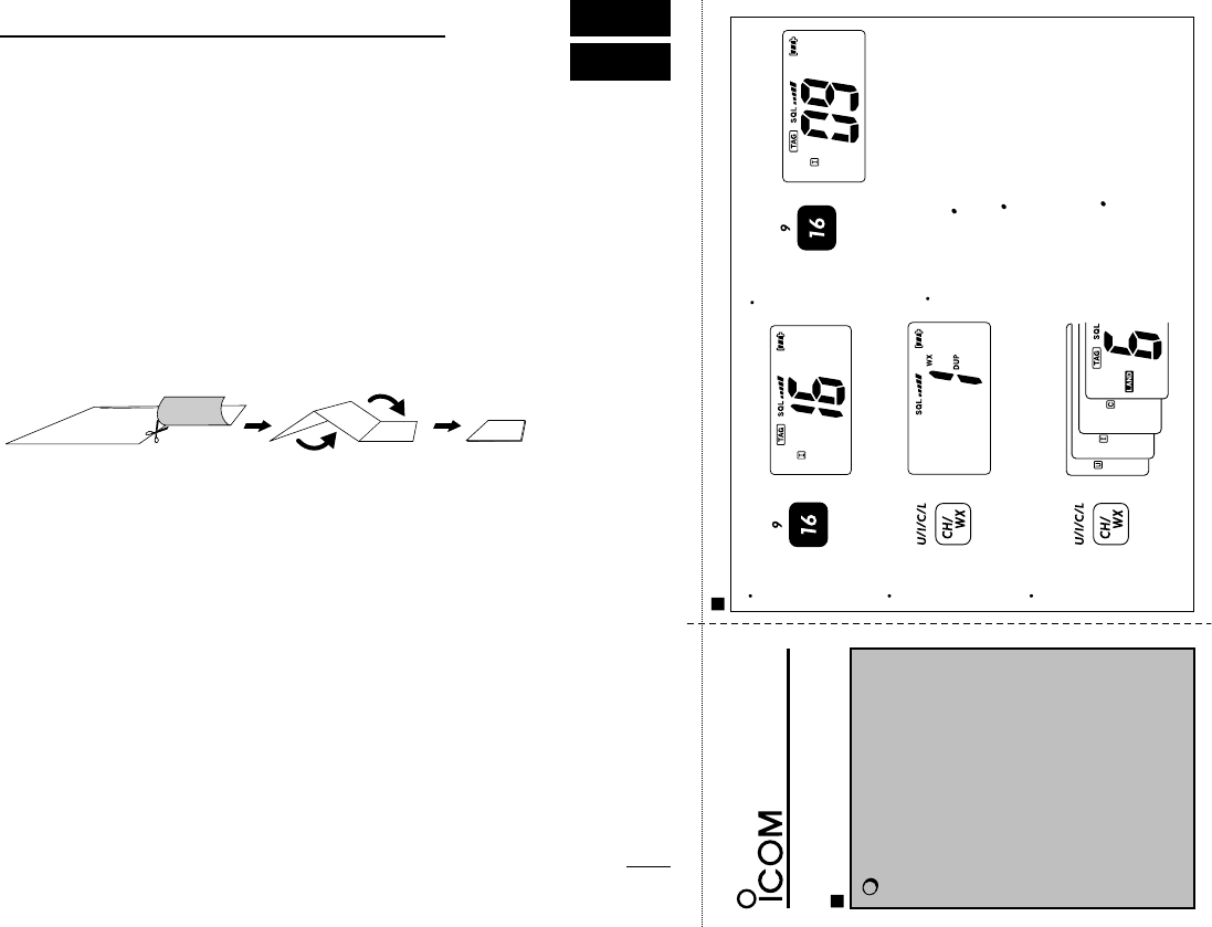
for your simple reference.
By cutting along the line and folding on the dotted line, it will become a card
sized operating guide which can easily be carried in a card case or wallet,
etc.
q Cut w Fold e Complete
<CUT HERE>
IC-M90.qxd 04.8.23 3:54 PM Page 31
TAG CHANNELS (p. 13)
q
w
Push [
Y
]/[
Z
] to select the desired
channel.
Push [
Y
]/[
Z
] for 1 sec. to change
the TAG setting ON and OFF.
WEATHER ALERT (pgs. 8, 17)
q
w
Turn the weather alert item in the
SET mode ON (p. 17).
Select WX channel; or start scan-
ning.
SET MODE (pgs. 16 21)
q
w
e
r
While pushing
[SQL MONI],
turn power ON.
Push [SQL
MONI
]
again to select an
item.
Push [
Y
]/[
Z
]
to select the desired
condition.
Push [16
9
] to return to regular op-
erating mode.
Refer to pgs. 15 20 for set
mode item.
DUALWATCH/TRI-WATCH (p. 14)
Select dual or tri-watch in the SET
mode (p. 18).
Push [
Y
]/[
Z
] to select the desired
channel.
Push [SCAN
D/T
] for 1 sec. to start
dualwatch or tri-watch (depending
on SET mode).
To cancel dualwatch/tri-watch,
push [SCAN
D/T
] again.
q
w
e
r
LOCK FUNCTION (p. 10)
Push [Hi/Lo ]
for 1 sec. to turn
the lock function
ON and OFF.
SQUELCH LEVEL (p. 11)
Push [SQL
MONI
], then adjust the
squelch level with [
Y
]/[
Z
].
Select monitor switch action in
SET mode (p. 18).
Push [SQL
MONI
] for 1sec. to ac-
tive the monitor function.
q
w
MONITOR FUNCTION (p. 10)
SCAN (pgs. 12, 13)
Push [SCAN
DIAL
] to start/stop
scanning.
32
IC-M90.qxd 04.8.23 3:54 PM Page 32

33
16
OPTIONS
16
DBATTERY CASE AND PACK
•BP-225 Ni-Cd
BATTERY PACK
7.2 V/1100 mAh Ni-Cd battery pack.
•BP-224 Ni-Cd
BATTERY PACK
7.2 V/750 mAh Ni-Cd battery pack.
•BP-223
BATTERY CASE
Battery case for 6 ×AA (R6) Alkaline cells.
DCHARGERS
•BC-119N
DESKTOP CHARGER
+ AD-109
CHARGER ADAPTER
+ BC-145A
AC ADAPTER
For rapid charging of battery packs. An AC adapter is supplied with
the charger depending on versions. Charging time: approx. 2.2 to
2.8 hours
•BC-121N
MULTI
-
CHARGER
+ AD-109
CHARGER ADAPTER
(6 pcs.)
+ BC-124
AC ADAPTER
For rapid charging of up to 6 battery packs (six AD-109’s are re-
quired) simultaneously. An AC adapter should be purchased sepa-
rately. Charging time: approx. 2.2 to 2.8 hours.
•BC-158
DESKTOP CHARGER
+ BC-147A
AC ADAPTER
Used for regular charging of battery pack. The same as supplied
with the transceiver. Charging time: approx. 12 hours
DBELT CLIPS
•MB-103
BELT CLIP
The same as supplied with the transceiver.
•MB-86
SWIVEL BELT CLIP
Belt clip for swivel type.
•MB-96F/96N
BELT HANGER
➥MB-96F: Attaches with the supplied belt clip (Not swivel type).
➥MB-96N: Belt hanger for swivel type.
DDC CABLES
•CP-17L
CIGARETTE LIGHTER CABLE
Allows to charge the battery pack through a 12 V cigarette lighter
socket. (For BC-119N)
•OPC-515L/OPC-656
DC POWER CABLES
Allows to charge the battery pack using 13.8 V power source in-
stead of the AC adapter.
OPC-515L: For BC-119N
OPC-656 : For BC-121N
DOTHER OPTIONS
•HM-125
SPEAKER
-
MICROPHONE
Full sized waterproof (JIS grade 7; 1m/30 min.) speaker-microphone
including alligator clip to attach to your shirt or collar. etc.
•HS-94/HS-95/HS-97
HEADSET
+ OPC-1392
HEADSET CABLE
HS-94: Ear-piece type
HS-95: Neck-arm type
HS-97: Throat microphone
Usable options are depended on versions. Ask your conve-
nient dealers or distributors for details.
IC-M90.qxd 04.8.23 3:54 PM Page 33

1-1-32 Kamiminami, Hirano-ku, Osaka 547-0003, Japan
A-6383H-1EX
Printed in Japan
©2004 Icom Inc.
IC-M90.qxd 04.8.23 3:54 PM Page 34