ICOM orporated 279521 VHF Marine Transceiver (GMDSS) User Manual IC GM1600 Instruction manual
ICOM Incorporated VHF Marine Transceiver (GMDSS) IC GM1600 Instruction manual
UserManual.wiki
>
ICOM orporated
>
279521 User Manual
>
Users Manual
Contents
1.
Users Manual
2.
Users manual
Users Manual
Navigation menu
Upload a User Manual
Namespaces
Wiki Guide
HTML
PDF
Info
Views
User Manual
Discussion / Help
Navigation
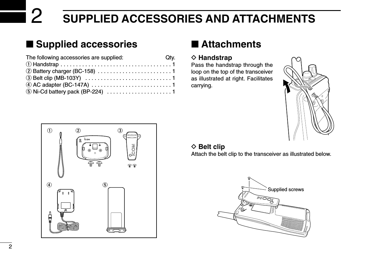
![4PANEL DESCRIPTION3■Front, top and side panelsqVOLUME CONTROL [VOL]Turns power ON and adjusts the audio level.wMICROPHONE CONNECTOR [SP MIC]Connects the optional external microphone.NOTE: Attach the [SP MIC] cap when the optionalspeaker-microphone is not used.eANTENNArTRANSMIT/RECEIVE INDICATORLights green while receiving a signal or when the squelchis open; lights red while transmitting (lights orange whileVOX function is used).tCALL CHANNEL SWITCH [CALL]➥Selects the call channel when pushed. (p. 7)- Channel 9 is factory default.➥Push for 3 sec. to enter call channel programming con-dition. (p. 9)yCHANNEL SWITCH [CH]Push to return the previous conditon when priolity channelor call channel is selected. (p. 7)uTRANSMIT POWER/LOCK SWITCH [Hi/Lo•]➥Selects high or low power when pushed. (p. 8)➥Toggles the lock function ON/OFF when pushed for1 sec. (p. 10)MIC /SPoq!1!0iytuerw](https://usermanual.wiki/ICOM-orporated/279521.Users-Manual/User-Guide-478667-Page-9.png)
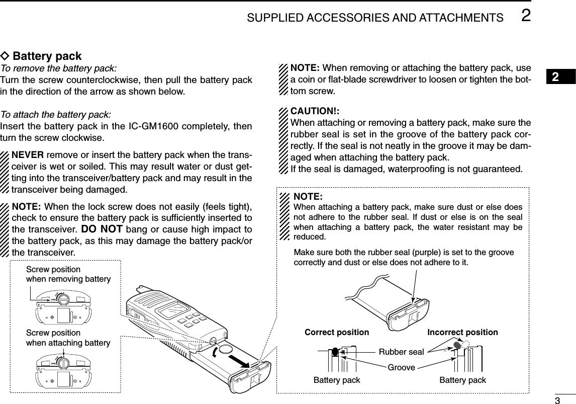
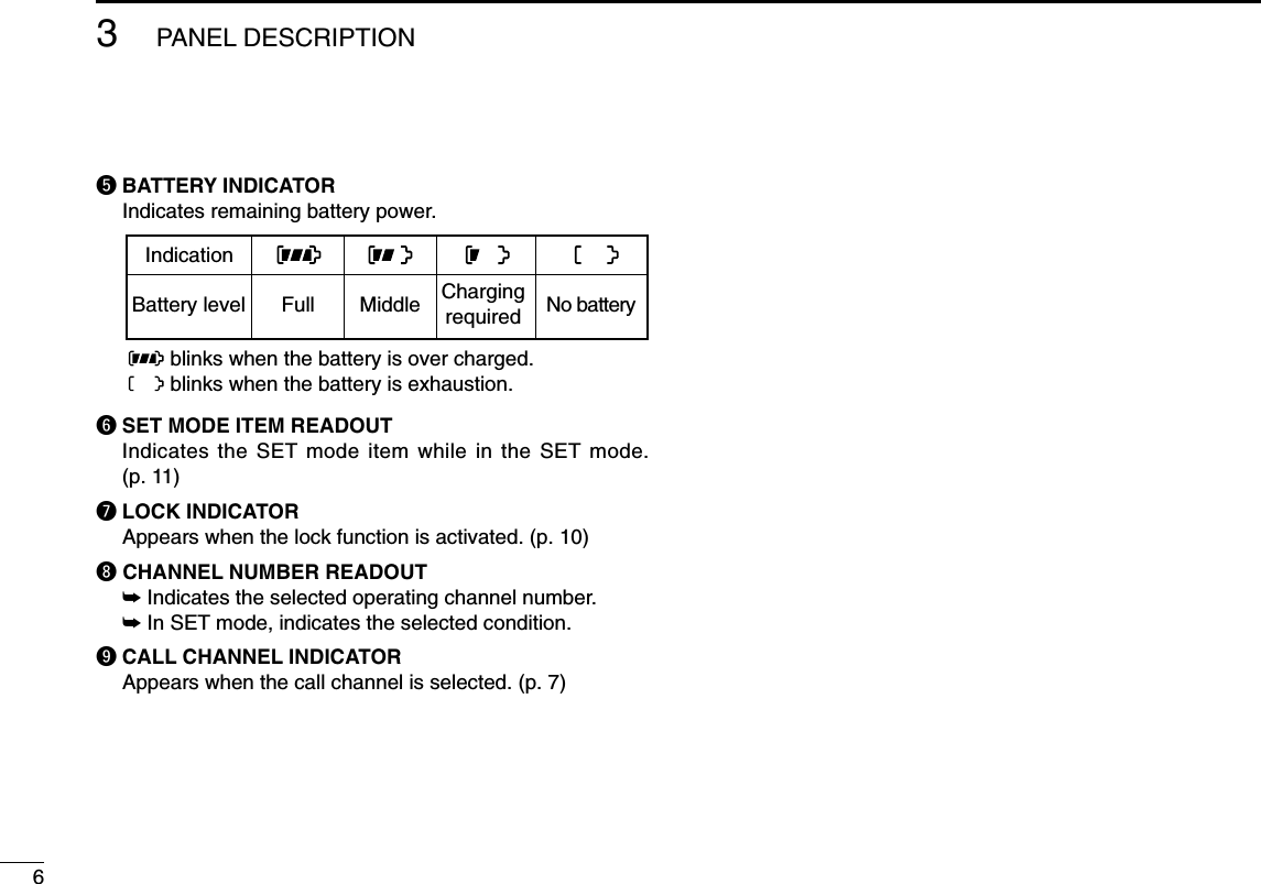
![53PANEL DESCRIPTIONiCHANNEL 16 SWITCH [16]Selects Channel 16 when pushed. (p. 7)oCHANNEL UP/DOWN SWITCHES [YY]/[ZZ]➥Selects an operating channel. (pgs. 7–8)➥Selects the SET mode condition of the item. (p. 11)➥Selects the SET mode item when pushed with [SQL].switch (p. 11)!0 SQUELCH SWITCH [SQL•MONI]➥Push this switch, then adjust the squelch level with[YY]/[ZZ]. (p. 9)➥Manually opens the squelch for monitoring the channelwhile pushed and held. (p. 10)➥While pushing this switch, turn power ON to enter theset mode. (p. 11)!1 PTT SWITCH [PTT]Push and hold to transmit; release to receive.■Function displayqSIGNAL STRENGTH INDICATOR (pgs. 10, 14)Shows the relative signal strength while receiving signals.wTRANSMIT POWER INDICATOR (p. 8)➥“LOW” appears when low power is selected.➥No indication appears when high power is selected.eSQUELCH LEVEL INDICATOR (p. 9)Show the squelch level.rMONITOR INDICATOR (p. 10)Appears when the monitor function is activated.qw r teyuio3](https://usermanual.wiki/ICOM-orporated/279521.Users-Manual/User-Guide-478667-Page-10.png)
![74BASIC OPERATION34■Channel selectionIMPORTANT!: Prior to using the transceiver for the firsttime, the battery pack must be fully charged for optimumlife and operation. To avoid damage to the transceiver, turnthe power OFF while charging.DChannel 16Channel 16 (Distress channel) is used for establishing initialcontact with another station and for emergency communica-tions. While standing by, you must monitor Channel 16.qPush [16] to select Channel 16.wPush [CH] to return to the condition before selecting Chan-nel 16, or push [Y]/[Z] to select the operating channel.DChannel 9 (Call channel)Channel 9 is the leisure-use call channel. The call channelscan be re-programmed (p. 9) and may be used to store yourmost often used channels for quick recall.qPush [CALL] to select the call channel.•“CALL” and the call channel number appear.•Call channel can be re-programmed. See the “Call channelprogramming” on p. 9 for details.wPush [CH] to return to the condition before selecting Chan-nel 9 (call channel), or push [Y]/[Z] to select the operatingchannel.PushPush](https://usermanual.wiki/ICOM-orporated/279521.Users-Manual/User-Guide-478667-Page-12.png)
![84BASIC OPERATION■Receiving and transmittingqRotate [VOL] clockwise to turn power ON.wSet the volume and squelch level.➥Push [SQL•MONI], and push [√] to open the squelch.➥Push [SQL•MONI] to stop “SQL” indicator blinking, thenrotate [VOL] to set the volume level.➥Push [SQL•MONI], and push [∫]/[√] to set the squelchlevel.ePush [Y]/[Z] to select the desired channel.- When receiving a signal, the [TRANSMIT/RECEIVE] indicatorlights green while audio is emitted from the speaker.- Further adjustment of [VOL] may be necessary at this point.rPush [Hi/Lo•] to select the output power if necessary.- “LOW” appears when low power is selected; no indication whenhigh power is selected.- Choose low power to conserve battery power, choose highpower for longer distance communications.- Some channels are for low power only.tPush and hold [PTT] to transmit, then speak into themicrophone.- The [TRANSMIT/RECEIVE] indicator lights red whiletransmitting.yRelease [PTT] to receive.IMPORTANT: To maximize the readability of your trans-mitted signal, pause a few sec. after pushing [PTT], holdthe microphone 5 to 10 cm (2 to 4 inches) from your mouthand speak into the microphone at a normal voice level.NOTE: The transceiver has a power save function to con-serve the battery power. The power save function activatesautomatically when no signal is received for 5 sec.CAUTION: Transmitting without an antenna maydamage the transceiver.MIC /SPq Power ONw Set volumer Set output power Speakert Push to transmity Release to receivew Set the squelch levele Set channelw Set the squelch levelMicrophone](https://usermanual.wiki/ICOM-orporated/279521.Users-Manual/User-Guide-478667-Page-13.png)
![94BASIC OPERATION4■Call channel programmingThe call channel switch is used to select Channel 9 by de-fault, however, you can program your most often-used chan-nel for quick recall.qPush [CALL] for 1 sec. to select thecall channel.•“CALL” and call channel numberappear.wPush [CALL] again for 3 sec. (until along beep changes to 2 short beeps)to enter call channel programmingcondition.•Call channel number to be programmedflashes.ePush [Y]/[Z] to select the desiredchannel.rPush [CALL] to program the dis-played channel as the call channel.•The call channel number stop flashing.■Adjusting the squelch levelTo adjust the IC-GM1600’s squelch level, use the [Y]/[Z] keysas desired below. In order to receive signals properly, as wellas for the scan to function effectively, the squelch must be ad-justed to the proper level.qPush [SQL•MONI], then adjust the squelch level with [Y]/[Z].- “SQL” indicator starts blinking.- There are 11 squelch levels to choose from: OP is completelyopen; 10 is tight squelch; 1 is loose squelch level.- When no switch is pushed for 5 sec., the transceiver returns tonormal condition.wPush [SQL•MONI] again to return to normal condition.Blinks during the squelch level adjutment.Indicates the squelch level.Push](https://usermanual.wiki/ICOM-orporated/279521.Users-Manual/User-Guide-478667-Page-14.png)
![104BASIC OPERATION■Lock functionThis function electronically locks all switches (except for[PTT], [SQL•MONI] and [Hi/Lo•]) to prevent accidentalchannel changes and function access.➥Push [Hi/Lo•] for 1 sec. to turn the lock function ONand OFF.■Signal strength indicatorfunctionThe received signal strength level is indicated by number ofbars as below.This indicator can be hidden by using the set mode (p. 14) ifdesired.■Monitor functionThe monitor function releases the noise squelch mute tocheck the volume level. See p. 12 for details of the monitorswitch action.➥Push [SQL•MONI] for 1 sec. to activate the monitor function.•“ ” appears and audio is emitted.■Backlighting functionThis function is convenient for nighttime operation. The back-lighting brightness can be adjusted in the SET mode. (p. 12)➥Push any switch except for [PTT] to turn the backlightingON.•The backlighting is automatically turned OFF after 5 sec. ofinactivity.IndicationStrong Middle Weak No signal or very weakSignalstrengthAppears while the lock function is used.Pushfor 1 sec.](https://usermanual.wiki/ICOM-orporated/279521.Users-Manual/User-Guide-478667-Page-15.png)
![115SET MODE45■SET mode programmingSET mode is used to change the condition of 9 transceiverfunctions: beep tone function, monitor switch action, back-lighting function, LCD contrast selection, auto power savefunction, self check function, battery voltage indicator, signalstrength indicator and squelch sensitivity function.DSET mode operationqTurn power OFF.wWhile pushing [SQL•MONI], turn power ON to enter theSET mode.• “bp” (Beep tone function setting) appears.ePush [SQL•MONI] or [SQL•MONI] and [Y]/[Z] to select thedesired item, if necessary.rPush [Y]/[Z] to select the desired condition of the item.tTo exit the SET mode, push [16].DSET MODE ITEMS The displays show the default settings, and the selected item is displayed in the dotted circle. Battery voltage Signal strength indicator Beep tone Monitor switch Backlighting LCD contrast Auto power save Self check Squelch sensitivity: Push: Push andStarting item Push and](https://usermanual.wiki/ICOM-orporated/279521.Users-Manual/User-Guide-478667-Page-16.png)
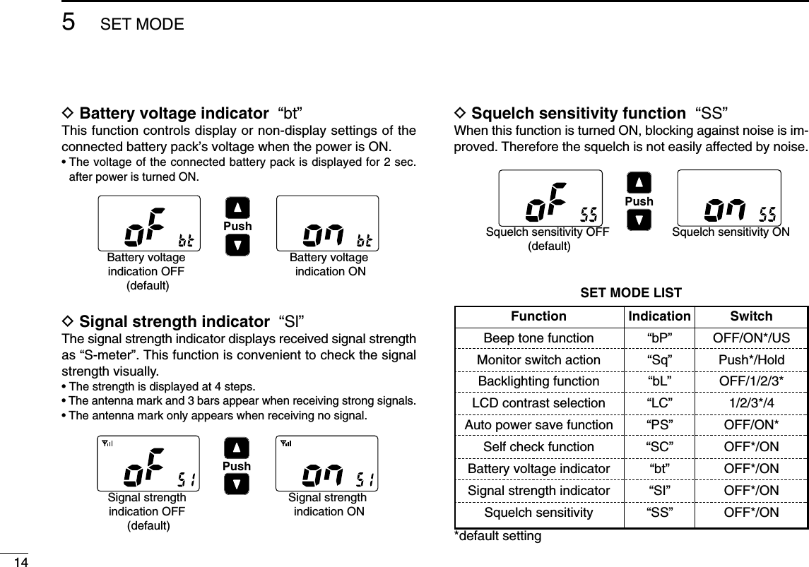
![125SET MODE■SET mode itemsDBeep tone function “bP”You can select silent operation by turning the beep tonesOFF, or you can have 2 types of confirmation beeps sound atthe push of a switch. When “ON” is selected, a fixed beep (Pi)sounds, and when “US” is selected, the preset beeps (e.g.do, re, mi) sound.• Beep tone synchronises with the volume level.• The beeps sound during call channel programming and a weatheralert tone indication even if this function is turned OFF.DMonitor switch action “Sq”The monitor switch action cuts off the squelch function tem-porarily. This switch action contains PUSH (Pu) or HOLD (Ho)settings as shown below.• Pu (PUSH): After pushing [SQL•MONI] for 1 sec., the squelch opensand emits audio. The squelch is held open while con-tinuously pushing and holding [SQL]. (default)• Ho (HOLD): After pushing [SQL•MONI] for 1 sec., the squelch opensand emits audio even [SQL•MONI] is released. To closethe squelch, push any switch.DBacklighting function “bL”This function is convenient for nighttime operation. The back-lighting brightness can be adjusted from OFF, 1 (dark)–3(bright); 3 (default). Select 1–3 to turn this function ON.• The automatic backlighting turns the backlighting ON when anyswitch except for [PTT] is pushed.• The backlighting is automatically turned OFF after 5 sec. of inactivity.DLCD contrast selection “LC”The contrast of the LCD can be adjusted from 4 levels.• 1 (bright)–4 (dark); 3 (default)PushBeep tone ON (default) Beep tone OFFPushPush setting (default) Hold settingPushBacklighting ON(default)Backlighting OFFPushMiddle contrast (default)Low contrast](https://usermanual.wiki/ICOM-orporated/279521.Users-Manual/User-Guide-478667-Page-17.png)

![30OPTIONAL SPEAKER-MICROPHONE9■HM-125 descriptionsNEVER immerse the connector in water. If the connector be-comes wet, be sure to dry BEFORE attaching it to the trans-ceiver.NOTE: The microphone is located at the top of thespeaker-microphone, as shown in the diagram above. Tomaximize the readability of your transmitted signal (voice),hold the microphone approx. 2.5 cm (1 inch) from yourmouth, and speak in a normal voice level.■AttachmentInsert the speaker-mic connector on to [SP MIC] connectorand carefully screw it tight, as shown in the diagram below.Be careful not to cross thread the connection.IMPORTANT: KEEP the transceiver’s [SP MIC] connectorcap attached when the speaker-microphone is not in use.Water will not get into the transceiver even if the cover isnot attached, however, the terminals (pins) will becomerusty, or the transceiver will function abnormally if the con-nector has become wet.Alligator type clipTo attach the speaker-mic.to your shirt or collar, etc.PTT switchTransmits during push.Receives during release.MicrophoneSpeakerSet the triangle mark to the front side.CAUTION: Attach the speaker-microphone’sconnector securely to prevent accidentaldropping, or water intrusion in the connector.Detaching:Pull up the capin the directionof the arrow todetach it.Attaching:Attach the capin the directionof the arrowcompletely.](https://usermanual.wiki/ICOM-orporated/279521.Users-Manual/User-Guide-478667-Page-25.png)
![3110TROUBLESHOOTING AND SURVIVAL CHANNELS910The transceiver doesnot turn ON.No sound from thespeaker.Transmitting is impos-sible, or high powercan not be selected.The displayed channelcannot be changed.No beeps.Self check error.(Temperature)Self check error.(Battery voltage)•The battery is exhausted.•Bad connection to the battery pack.•Squelch level is too deep.•Volume level is too low.•Speaker has been exposed to water.• Water has entered to [SP MIC] connector.•Some channels are for low power or re-ceive only.•The battery is exhausted.•The battery is over charged.•The output power is set to low.•Lock function is activated.•Beep tones are turned OFF.•The temperature is outside of –35°C to+80°C; –31°F to +173°F (approx.).•The connected battery pack’s voltage ismore than 11 V.•Recharge the battery pack.•Check the connection to the transceiver.•Set squelch to the threshold point.•Rotate [VOL] to set a suitable level.•Drain water from the speaker.• Dry [SP MIC] connector.•Change channels.•Recharge the battery pack.•Verify the battery voltage is correct.•Push [Hi/Lo•] to select high power.•Push [Hi/Lo•] for 1 sec. to cancel thefunction.•Set the beep tones to ON (Fix Beep/UserBeep) on the SET mode.•Leave the transceiver at room temperaturefor a while. Turn the power ON to check if theinternal temperature has returned to normal.•Verify the battery voltage is correct.p. 22p. 3p. 9p. 8——pgs. 8,29p. 22—p. 8p. 10p. 12——PROBLEM POSSIBLE CAUSE SOLUTION REF.• TROUBLESHOOTING• SURVIVAL CHANNELSCH TX/RX CH TX/RX CH TX/RX CH TX/RX CH TX/RX CH TX/RX CH TX/RX CH TX/RX06 156.300 08 156.400 09 156.450 10 156.500 11 156.550 12 156.600 13 156.650 14 156.70015* 156.750 16 156.800 17* 156.850 67 156.375 68 156.425 69 156.475 71 156.575 72 156.62573 156.675 74 156.725 77 156.875 *Low power onlyUnit: MHz](https://usermanual.wiki/ICOM-orporated/279521.Users-Manual/User-Guide-478667-Page-26.png)