ICOM orporated 279521 VHF Marine Transceiver (GMDSS) User Manual IC GM1600 FCC TX HPF
ICOM Incorporated VHF Marine Transceiver (GMDSS) IC GM1600 FCC TX HPF
UserManual.wiki
>
ICOM orporated
>
279521 User Manual
>
Users manual
Contents
1.
Users Manual
2.
Users manual
Users manual
Navigation menu
Upload a User Manual
Namespaces
Wiki Guide
HTML
PDF
Info
Views
User Manual
Discussion / Help
Navigation


![iiiRECOMMENDATIONCLEAN THE TRANSCEIVER THOROUGHLY WITH FRESH WATER after exposure to saltwater, and dry it before operat-ing. Otherwise, the transceiver's keys, switches and control-lers may become unusable, due to salt crystallization, and/or the charging terminals of the battery pack may rust.NOTE: DO NOT wash the transceiver in water if there is any reason to suspect the waterproofing may not be effective. For example, in cases where the [SP MIC] jack cover is damaged, the transceiver/battery pack is cracked or broken, or has been dropped, or when the battery pack is detached from the transceiver.FOREWORDThank you for purchasing this Icom radio. The IC-GM1600 SURVIVAL CRAFT 2-WAY RADIO is designed and built with Icom’s state of the art technology and craftsmanship. With proper care, this product should provide you with years of trou-ble-free operation.MIC /SP](https://usermanual.wiki/ICOM-orporated/279521.Users-manual/User-Guide-3216250-Page-4.png)


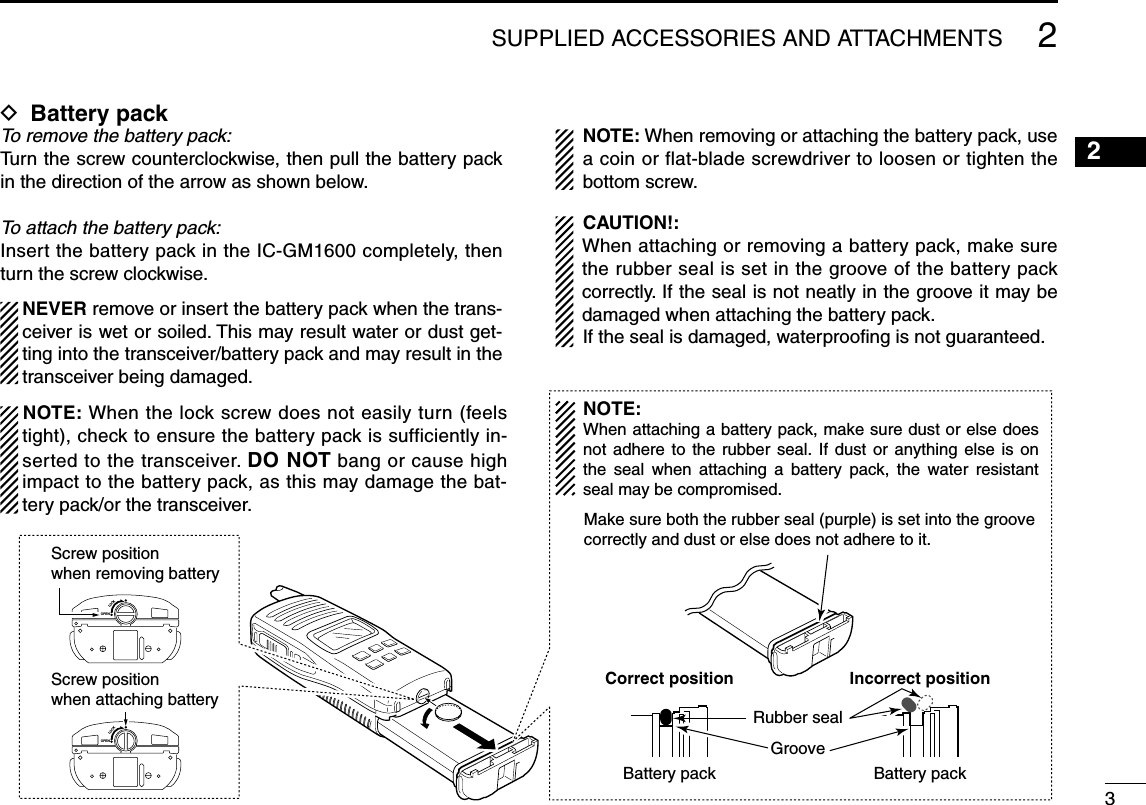
![New20014PANEL DESCRIPTION■ Front, top and side panelsq VOLUME CONTROL [VOL] Turns power ON and adjusts the audio level.w MICROPHONE CONNECTOR [MIC/SP] Connects the optional external microphone. NOTE: Attach the [MIC/SP] cap when the optional speak-er-microphone is not used.e ANTENNA Fixed type.r TRANSMIT/RECEIVE INDICATOR Lights green while receiving a signal or when the squelch is open; lights red while transmitting.t CALL CHANNEL KEY [CALL] ➥ Selects the call channel when pushed. (p. 7) • Channel 9* is factory default. *Channel 16 is set as factory default by version. ➥ Push for 3 sec. to enter call channel programming con-dition. (p. 9)y CHANNEL KEY [CH] Push to return the previous condition when distress chan-nel or call channel is selected. (p. 7)u TRANSMIT POWER/LOCK KEY [Hi/Lo• ] ➥ Selects high or low power when pushed. (p. 8) ➥ Toggles the lock function ON/OFF when pushed for 1 sec. (p. 10)3MIC /SPoq!1!0iytuerw](https://usermanual.wiki/ICOM-orporated/279521.Users-manual/User-Guide-3216250-Page-12.png)
![3PANEL DESCRIPTION35i CHANNEL 16 KEY [16] Selects Channel 16 when pushed. (p. 7)o CHANNEL UP/DOWN KEYS [Y]/[Z] ➥ Selects an operating channel. (pgs. 7–8) ➥ Selects the SET mode condition of the item. (p. 11) ➥ Selects the SET mode item when pushed with [SQL]. (p. 11)!0 SQUELCH SWITCH [SQL•MONI] ➥ Push this switch, then adjust the squelch level with [Y]/[Z]. (p. 9) ➥ Manually opens the squelch for monitoring the channel while pushed and held. (p. 10) ➥ While pushing this switch, turn power ON to enter the SET mode. (p. 11)!1 PTT SWITCH [PTT] Push and hold to transmit; release to receive.](https://usermanual.wiki/ICOM-orporated/279521.Users-manual/User-Guide-3216250-Page-13.png)
![4■ Channel selectionD Channel 16Channel 16 (Distress channel) is used for establishing initial contact with another station and for emergency communica-tions. While standing by, you must monitor Channel 16.q Push [16] to select Channel 16.w Push [CH] to return to the condition before selecting Channel 16, or push [Y]/[Z] to select the operating chan-nel.PushD Call channelThe call channels can be re-programmed (p. 9) and may be used to store your most often used channels for quick recall.q Push [CALL] to select the call channel. • “CALL” and the call channel number appear. • Call channel can be re-programmed. See the “Call channel programming” on p. 9 for details.w Push [CH] to return to the condition before selecting the call channel, or push [Y]/[Z] to select the operating chan-nel.Push74BASIC OPERATION](https://usermanual.wiki/ICOM-orporated/279521.Users-manual/User-Guide-3216250-Page-15.png)
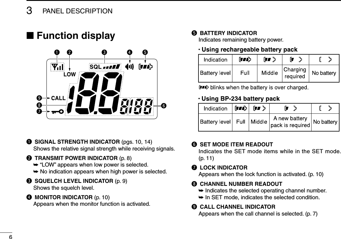
![4BASIC OPERATION8■ Receiving and transmittingq Rotate [VOL] clockwise to turn power ON.w Set the volume and squelch level. ➥ Push [SQL•MONI], and push [Z] to open the squelch. ➥ Push [SQL•MONI] to stop the “SQL” indicator blinking, then rotate [VOL] to set the volume level. ➥ Push [SQL•MONI], and push [Y]/[Z] to set the squelch level.e Push [Y]/[Z] to select the desired channel. - When receiving a signal, the [TRANSMIT/RECEIVE] indicator lights green while audio is emitted from the speaker. - Further adjustment of [VOL] may be necessary at this point.r Push [Hi/Lo• ] to select the output power if necessary. - “LOW” appears when low power is selected; no indication when high power is selected. - Choose low power to conserve battery power, choose high power for longer distance communications. - Some channels are for low power only.t Push and hold [PTT] to transmit, then speak into the microphone. - The [TRANSMIT/RECEIVE] indicator lights red while transmitting.y Release [PTT] to receive. IMPORTANT: To maximize the readability of your transmit-ted signal, pause a moment after pushing [PTT], hold the microphone 5 to 10 cm (2 to 4 inches) from your mouth and speak into the microphone at a normal voice level. NOTE: The transceiver has a power save function to con-serve the battery power. The power save function acti-vates automatically when no signal is received for 5 sec.MIC /SPq Power ONw Set volumer Select output power Speakert Push to transmity Release to receivew Set the squelch levele Select channelw Set the squelch levelMicrophone](https://usermanual.wiki/ICOM-orporated/279521.Users-manual/User-Guide-3216250-Page-16.png)
![4BASIC OPERATION94■ Call channel programmingThe call channel switch is used to select Channel 9* by de-fault, however, you can program your most often-used chan-nel for quick recall.*The channel number depends on version.q Push [CALL] to select the call chan-nel. • “CALL” and call channel number appear.w Push [CALL] again for 3 sec. (until a long beep changes to 2 short beeps) to enter call channel pro-gramming condition. • Call channel number to be pro-grammed flashes.e Push [Y]/[Z] to select the desired channel.r Push [CALL] to program the dis-played channel as the call channel. • The call channel number stops flash-ing.■ Adjusting the squelch levelTo adjust the IC-GM1600’s squelch level, use the [Y]/[Z] keys. In order to receive signals properly, the squelch must be ad-justed to the proper level.q Push [SQL•MONI], then adjust the squelch level with [Y]/[Z]. - “SQL” indicator starts blinking. - There are 11 squelch levels to choose from: OP is completely open; 10 is tight squelch; 1 is loose squelch level.w Push [SQL•MONI] again to return to normal condition. - When no switch is pushed for 5 sec., the transceiver returns to normal condition.Blinks during the squelch level adjutment.Indicates the squelch level.Push](https://usermanual.wiki/ICOM-orporated/279521.Users-manual/User-Guide-3216250-Page-17.png)
![4BASIC OPERATION10■ Lock functionThis function electronically locks all keys (except for [PTT], [SQL•MONI] and [Hi/Lo• ]) to prevent accidental channel changes and function access.➥ Push [Hi/Lo• ] for 1 sec. to turn the lock function ON and OFF.■ Signal strength indicatorThe received signal strength level is indicated by number of bars as below.• Only the antenna mark appears when receiving no signal or a very weak signal when the signal strength indicator is set to ON in the SET mode (p. 14).• This indicator can be hidden by using the SET mode (p. 14) if de-sired.■ Monitor functionThe monitor function releases the noise squelch mute to check the volume level. See p. 12 for details of the monitor switch action.➥ Push [SQL•MONI] for 1 sec. and keep holding to activate the monitor function. • “ ” appears and audio is emitted.■ Backlit functionThis function is convenient for night time operation. The backlit brightness can be adjusted in the SET mode. (p. 12)➥ Push any key except for [PTT] to turn the backlit ON. • “ ” appears and audio is emitted. The backlit is automatically turned OFF after 5 sec. of inactivity.IndicationStrong Middle Weak No signal orVery weakSignalstrengthAppears while the lock function is used.Pushfor 1 sec.](https://usermanual.wiki/ICOM-orporated/279521.Users-manual/User-Guide-3216250-Page-18.png)
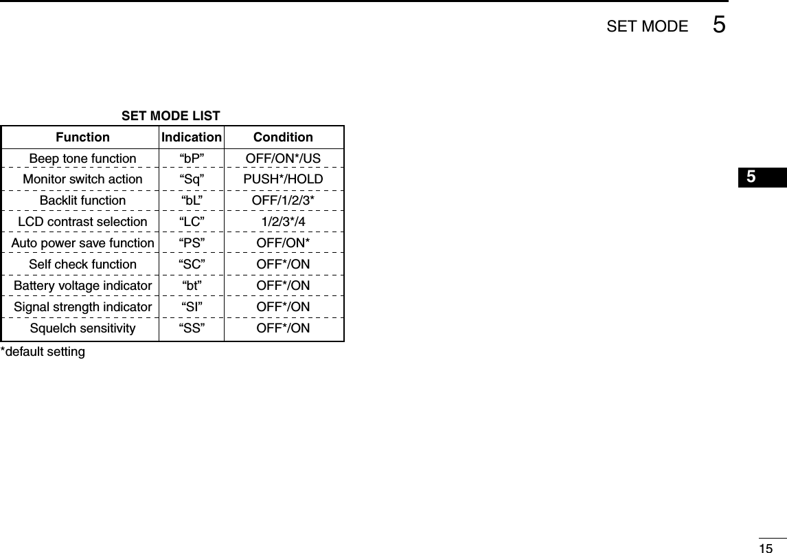
![5■ SET mode programmingSET mode is used to change the condition of 11 transceiver functions: beep tone function, monitor switch action, backlit function, LCD contrast selection, auto power save function, self check function, battery voltage indicator, signal strength indicator and squelch sensitivity function.D SET mode operationq Turn power OFF.w While pushing [SQL•MONI], turn power ON to enter the SET mode. • “bp” (Beep tone function setting) appears.e Push [SQL•MONI] or [SQL•MONI] and [Y]/[Z] to select the desired item, if necessary.r Push [Y]/[Z] to select the desired condition of the item.t Push [16] to exit the SET mode.D SET MODE ITEMS The displays show the default settings, and the selected item is displayed in the dotted circle.11 Beep tone Monitor switch: Push: Push andStarting item Push and Battery voltage Backlighting Auto power save Self check Squelch sensitivity LCD contrast Signal strength indicator5SET MODE](https://usermanual.wiki/ICOM-orporated/279521.Users-manual/User-Guide-3216250-Page-19.png)
![5SET MODE12■ SET mode itemsD Beep tone function “bP”You can select silent operation by turning the beep tones OFF, or you can have 2 types of confirmation beeps sound at the push of a key. When “ON” is selected, a fixed beep (Pi) sounds, and when “US” is selected, the preset beeps (e.g. do, re, mi) sound.• Beep tone synchronizes with the volume level.• The beeps sound during call channel programming even if this function is turned OFF.D Monitor switch action “Sq”The monitor switch action cuts off the squelch function tem-porarily. This switch action contains PUSH (Pu) or HOLD (Ho) settings as shown below.• PU (PUSH): After pushing [SQL•MONI] for 1 sec., the squelch opens and emits audio. The squelch is held open while continuously pushing and holding [SQL•MONI]. (default)• HO (HOLD): After pushing [SQL•MONI] for 1 sec., the squelch opens and emits audio even if [SQL•MONI] is re-leased. To close the squelch, push any switch.D Backlit function “bL”This function is convenient for nighttime operation. The back-lit brightness can be adjusted from OFF, 1 (dark)–3 (bright); 3 (default). Select 1–3 to turn this function ON.• The automatic backlit turns the backlit ON when any switch except for [PTT] is pushed.• The backlit is automatically turned OFF after 5 sec. of inactivity.D LCD contrast selection “LC”The contrast of the LCD can be adjusted from 4 levels.• 1 (bright)–4 (dark); 3 (default)PushBeep tone ON (default) Beep tone OFFPushPUSH setting (default) HOLD settingPushBacklighting ON(default)Backlighting OFFPushMiddle contrast (default)Low contrast](https://usermanual.wiki/ICOM-orporated/279521.Users-manual/User-Guide-3216250-Page-20.png)


![101121The transceiver does not turn ON.No sound from the speaker.Transmitting is impos-sible, or high power can not be selected.The displayed channel cannot be changed.No beeps.Self check error.(Temperature)Self check error.(Battery voltage)• The battery is exhausted.• Bad connection to the battery pack.• Squelch level is too deep.• Volume level is too low.• Speaker has been exposed to water.• Water has entered the [MIC/SP] connector.• Some channels are for low power or re-ceive only.• The battery is exhausted.• The output power is set to low.• Lock function is activated.• Beep tones are turned OFF.• The temperature is outside of –35°C to +80°C; –31°F to +173°F (approx.).• The connected battery pack’s voltage is more than 11 V.• Change to a new battery pack (Survival).• Recharge the battery pack (On-board).• Check the connection to the transceiver.• Set squelch to the threshold point.• Rotate [VOL] to set a suitable level.• Drain water from the speaker.• Dry [MIC/SP] connector.• Change channels.• Change to a new battery pack (Survival).• Recharge the battery pack (On-board).• Push [Hi/Lo• ] to select high power.• Push [Hi/Lo• ] for 1 sec. to cancel the function.• Set the beep tones to ON (Fix Beep/User Beep) on the SET mode.• Leave the transceiver at room temperature for a while. Turn the power ON to check if the internal temperature has returned to normal.• Verify the battery voltage is correct.p. 16pgs. 17–20p. 3p. 9p. 8——pgs. 8, 23p. 16pgs. 17–20p. 8p. 10p. 12—— PROBLEM POSSIBLE CAUSE SOLUTION REF�10TROUBLESHOOTING](https://usermanual.wiki/ICOM-orporated/279521.Users-manual/User-Guide-3216250-Page-29.png)
![22SPECIFICATIONS11D GENERAL• Frequency coverage (TX/RX) : 156.300–156.875 MHz• Mode : 16K0G3E• Channel spacing : 25 kHz• Power supply requirement : Battery packs (BP-234 or BP-252)• Current drain (approx.) : TX High (2 W) 1.0 A at 7.5 V DC [USA] TX Low (1 W) 700 mA at 7.2 V DC [GEN] Max. audio 200 mA• Usable temperature range : [USA] –20°C to +60°C; –4°F to +140°F [GEN] –20°C to +55°C; –4°F to +131°F• Antenna impedance : 50 Ω• Dimensions : 65(W) × 145(H) × 44(D) mm (Projections not included) 29/16(W) × 523/32(H) × 13/4(D) inch• Weight (with BP-234) : Approx. 385 g (13.6 oz)D TRANSMITTER• Output power : 2 W (Hi) and 1 W (Low) at 7.5 V DC [USA] at 7.2 V DC [GEN] • Modulation system : Variable reactance frequency modulation• Frequency error : [USA] ±5.0 ppm (–20°C to +60°C; –4°F to +140°F) [GEN] ±1.5 kHz (–20°C to +55°C; –4°F to +131°F)• Microphone impedance : 2 kΩ• Max. frequency deviation : ±5.0 kHz• Adjacent channel power : 70 dB• Audio harmonics distortion : 10% at 60% deviation• FM hum and noise : 40 dB • Spurious emissions : [USA] –70 dBc typical [GEN] 0.25 µW (30 MHz to 1 GHz) 1 µW (1–2 GHz)D RECEIVER• Receive system : Double-conversion superheterodyne• Sensitivity : [USA] (at 12 dB SINAD) 0.25 µV typical [GEN] (at 20 dB SINAD) –2 dBµ EMF typical• Squelch sensitivity (at threshold) : [USA] 0.35 µV typical [GEN] –6 dBµ EMF typical• Intermodulation rejection ratio : [USA] 70 dB [GEN] 68 dB• Spurious response rejection ratio : 70 dB• Adjacent channel selectivity : 70 dB• Hum and noise : 40 dB• Audio output power : [USA] 0.35 W typical at 10% distor-tion with an 8 Ω load. [GEN] 0.20 W at 10% distortion with an 8 Ω load.All stated specifications are subject to change without notice or obligation�](https://usermanual.wiki/ICOM-orporated/279521.Users-manual/User-Guide-3216250-Page-30.png)