ICOM orporated 284400 Scanning Receiver User Manual IC R9500 manual
ICOM Incorporated Scanning Receiver IC R9500 manual
UserManual.wiki
>
ICOM orporated
>
284400 User Manual
>
Users Manual 1
Contents
1.
Users Manual 1
2.
Users Manual 2
3.
Users Manual 3
Users Manual 1
Navigation menu
Upload a User Manual
Namespaces
Wiki Guide
HTML
PDF
Info
Views
User Manual
Discussion / Help
Navigation
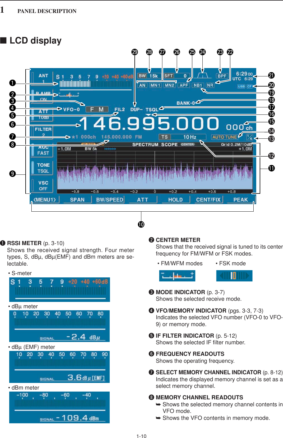
![iiPRECAUTIONSRWARNING! NEVER operate the receiver with aheadset or other audio accessories at high volumelevels. Hearing experts advise against continuous highvolume operation. If you experience a ringing in yourears, reduce the volume or discontinue use.RCAUTION! NEVER change the internal set-tings of the receiver. This may reduce receiver perfor-mance and/or damage to the receiver.The receiver warranty does not cover any problemscaused by unauthorized internal adjustment.RCAUTION! The receiver weighs approx. 20 kg(44 lb). Always have two people available to carry, liftor turn over the receiver. RCAUTION! The line-voltage receptacle must benear the receiver and must be easily accessible. Avoidextension cords.RACHTUNG! Die Steckdose muß nabe beidiesem Gerät angebracht und zugänglich sein.RNEVER let metal, wire or other objects protrudeinto the receiver or into connectors on the rear panel.This may result in an electric shock.RNEVER block any cooling vents on the top, rearor bottom of the receiver.RNEVER expose the receiver to rain, snow or anyliquids.RNEVER install the receiver in a place without ad-equate ventilation. Heat dissipation may be reduced,and the receiver may be damaged.RNEVER operate or touch the receiver with wethands. This may result in an electric shock or damageto the receiver.DO NOTuse chemical agents such as benzine or al-cohol when cleaning the IC-R9500, as they can dam-age the receiver’s surfaces.AVOID using or storing the receiver in areas with tem-peratures below ±0°C (+32°F) or above +50°C(+122°F).AVOID placing the receiver in excessively dusty envi-ronments or in direct sunlight.AVOID placing the receiver against walls or puttinganything on top of the receiver. This may overheat thereceiver.Always place unit in a secure place to avoid inadver-tent use by children.The LCD display may have cosmetic imperfections thatappear as small dark or light spots. This is not a mal-function or defect, but a normal characteristic of LCDdisplays.During maritime mobile operation, keep the receiver asfar away as possible from the magnetic navigationcompass to prevent erroneous indications.Turn [I/O] switch (on the rear panel) OFF and/or dis-connect the AC power cable from the AC outlet whenyou will not use the receiver for a long period of time.For U.S.A. onlyCAUTION: Changes or modifications to this device,not expressly approved by Icom Inc., could void yourauthority to operate this device under FCC regulations.ABOUT APCO PROJECT 25This device made under license under one or more ofthe following US patents: #4,590,473, #4,636,791,#5,148,482, #5,185,796, #5,271,017, #5,377,229.The IMBE™ voice coding technology embodied in thisproduct is protected by intellectual property rightsincluding patent rights, copyrights and trade secrets ofDigital Voice Systems, Inc. This voice codingTechnology is licensed solely for use within this com-munications equipment. The user of this technology isexplicitly prohibited from attempting to decompile,reverse engineer, or disassemble the object code, orin any other way convert the object code into ahuman-readable form. U.S. Pat. nos. #5,870,405,#5,826,222, #5,754,974, #5,701,390, #5,715,365,#5,649,050, #5,630,011, #5,581,656, #5,517,511,#5,491,772, #5,247,579, #5,226,084, #5,195,166.P25 digital mode is available when the optional UT-122 DIGITAL UNIT is installed.](https://usermanual.wiki/ICOM-orporated/284400.Users-Manual-1/User-Guide-760164-Page-3.png)
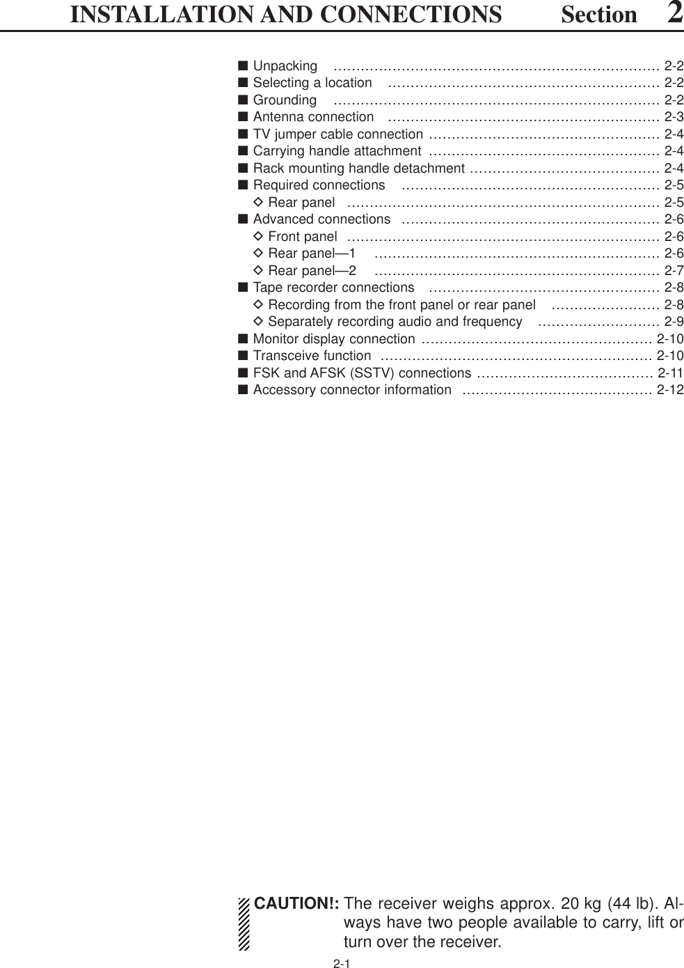
![vi■Noise reduction ………………………………………………………… 5-16■Notch function ………………………………………………………… 5-16■Autotune function ……………………………………………………… 5-17■AFC function …………………………………………………………… 5-17Section 6 VOICE RECORDER FUNCTIONS■About digital voice recorder …………………………………………… 6-2■Recording a received audio …………………………………………… 6-3DRegular recording …………………………………………………… 6-3■Playing the recorded audio …………………………………………… 6-3DRegular playing ……………………………………………………… 6-3■Erasing the recorded contents ………………………………………… 6-4■Selecting the CF memory card or USB-Memory …………………… 6-4■Short recording ………………………………………………………… 6-5DRecording …………………………………………………………… 6-5DPlaying back ………………………………………………………… 6-5■Voice set mode ………………………………………………………… 6-6Section 7 MEMORY OPERATION■Memory channels ……………………………………………………… 7-2■Memory channel selection …………………………………………… 7-3DUsing the [M-CH]/[BANK] selectors ……………………………… 7-3DUsing the keypad …………………………………………………… 7-3■Memory channel programming ……………………………………… 7-4DProgramming in VFO mode ………………………………………… 7-4DProgramming in memory mode …………………………………… 7-4■Frequency transferring ………………………………………………… 7-5DTransferring in VFO mode ………………………………………… 7-5DTransferring in memory mode ……………………………………… 7-5■Memory names ………………………………………………………… 7-6DEditing (programming) memory names …………………………… 7-6■Memory clearing ………………………………………………………… 7-6■Memory list screen ……………………………………………………… 7-7DSelecting a memory channel using the memory list screen …… 7-7DConfirming programmed memory channels ……………………… 7-7DMemory bank set …………………………………………………… 7-8Section 8 SCANS■Scan types ……………………………………………………………… 8-2■Preparation ……………………………………………………………… 8-3■Voice squelch control function ………………………………………… 8-3■Scan set mode ………………………………………………………… 8-4■Priority scan ……………………………………………………………… 8-5DSetting ………………………………………………………………… 8-5DPriority scan operation ……………………………………………… 8-5■Programmed scan ……………………………………………………… 8-6DSetting ………………………………………………………………… 8-6DProgram scan operation …………………………………………… 8-7■∂F scan ………………………………………………………………… 8-8DSetting ………………………………………………………………… 8-8D∂F scan operation …………………………………………………… 8-8■Fine programmed scan/fine ∂F scan operation……………………… 8-9■Auto memory write scan operation…………………………………… 8-10TABLE OF CONTENTS](https://usermanual.wiki/ICOM-orporated/284400.Users-Manual-1/User-Guide-760164-Page-7.png)
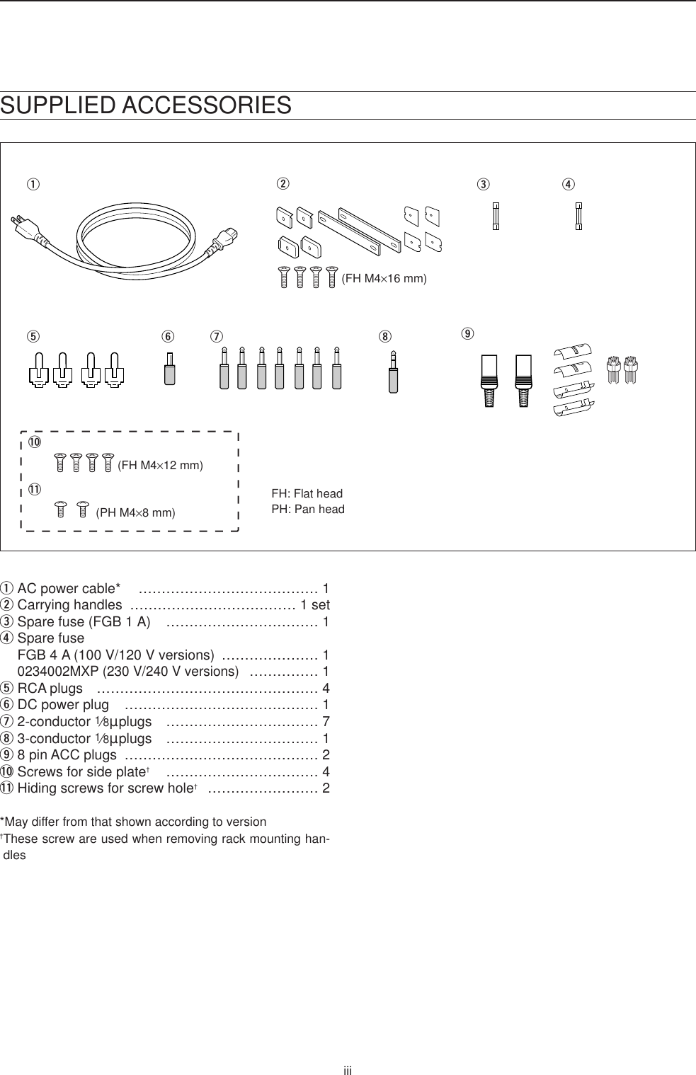
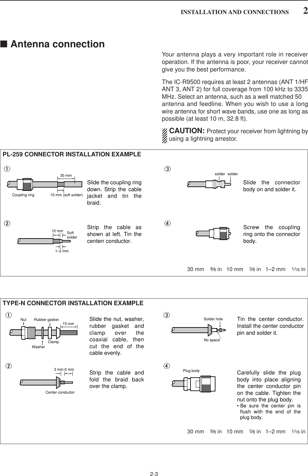
![1-2■Front panelqPOWER SWITCH [POWER] (p. 3-2)➥Push to turn the receiver power ON.• The [POWER] indicator above this switch lights greenwhen powered ON.➥Push for 1 sec. to turn the receiver power OFF.• The [POWER] indicator lights orange when the re-ceiver is OFF when the internal power supply isswitched ON.wREMOTE CONTROL SWITCH [LOCAL]Push to cancel remote control operation from a PCvia a CI-V data.• The [REMOTE] indicator lights yellow while in remotecontrol operation.• When the [REMOTE] indicator lights yellow, all dials,keys or switches other than this switch are disabled.ePANEL LOCK SWITCH [PANEL LOCK] (p. 9-2)Push to turn the panel lock function ON or OFF. Thepanel lock function locks all dials, keys and switchesother than [POWER] and [PANEL LOCK]. • The [PANEL LOCK] indicator above this switch lightsyellow when the timer is in use.• The dial lock function is also available.rTIMER SWITCH [TIMER] (p. 10-3)➥Turns the sleep or daily timer function ON orOFF.• The [TIMER] indicator above this switch lights greenwhen the timer is in use.➥Enters timer set mode when pushed and held for1sec.tRECORDER REMOTE JACK [REC REMOTE]Controls the operation of a tape recorder for record-ing. Connects to the REMOTE jack on a taperecorder.yRECORDER JACK [REC OUT]Outputs an audio signal. Connect to the AUX orLINE IN jack on a tape recorder.uHEADPHONE JACK [PHONES]Accepts standard 3.5 (d) mm (1⁄8) stereo head-phones.• Output power: 40 mW with an 8 load.• When headphones are connected, the internal speakeror connected external speaker does not function.iSQUELCH CONTROL [SQUELCH] (p. 3-8)Adjusts the squelch threshold level. The squelchdisables output from the speaker (closed condition)when no signal is received.• The squelch control is particularly effective for FM orAM. It is also available for other modes.• 11 to 12 o’clock position is recommended for any set-ting of the [SQL] control.DeepDeepS-metersquelchNoise squelchSquelchis open.SquelchthresholdShallow ShallowTurn the internal power supply ON before turning theunit ON from the front panel. The internal power sup-ply switch is located on the rear panel. (p. 3-2)1PANEL DESCRIPTIONi!0qwertyuo!1 !2!3 !4 !5 !8!6 !7](https://usermanual.wiki/ICOM-orporated/284400.Users-Manual-1/User-Guide-760164-Page-12.png)
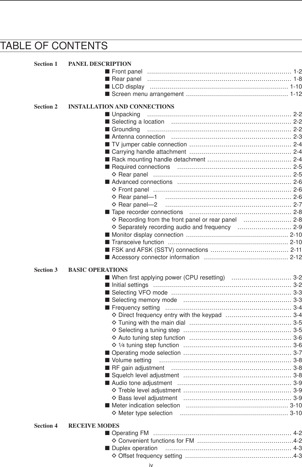
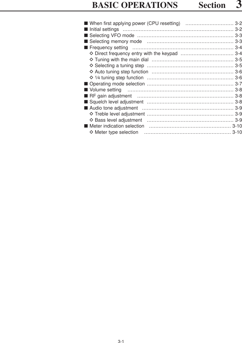
Adjusts the IF filter “passband width” via the DSP. • Passband width and shift frequency are shown on themultifunction display.• Push and hold [PBT CLEAR] for 1 sec. to clear the PBTsettings.• Variable range is set to half of the IF filter passbandwidth. 25 Hz steps and 50 Hz steps are available inSSB, CW and FSK modes.✔What is the PBT control?The PBT function electronically modifies the IF passbandwidth to reject interference. This receiver uses the DSP cir-cuit for the PBT function.!0 PBT CLEAR SWITCH [PBT CLEAR] (p. 5-11)Push and hold for 1 sec. to clear the PBT settings.• The [PBT CLEAR] indicator above this switch lightswhen PBT is in use.!1 AGC CONTROL [AGC] (p. 5-10)Adjusts the continuously-variable AGC circuit timeconstant.• To use [AGC] control, push the appropriate band’s[AGC VR/OFF] ([AGC VR] indicator lights green).!2 AGC SWITCH [AGC VR/OFF] (p. 5-10)➥Push to toggle [AGC] control usage ON or OFF.• Use [AGC] control to set the AGC time constant whenswitched ON.• The [AGC VR] indicator above this switch lightsgreen when the control is ON.➥Turns the AGC function OFF when pushed andheld for 1 sec.!3 AUTO NOTCH SWITCH [ANF] (p. 5-16)➥Turns the auto notch function ON or OFF whenpushed in SSB, AM, FM and WFM mode.• “ ” appears when auto notch is in use.!4 MANUAL NOTCH SWITCHES[NOTCH1]/[NOTCH2] (p. 5-16)➥Turns the manual notch function ON or OFFwhen pushed in SSB, CW, AM and FSK mode.• “ ” or “ ” appear when manual notch is in use.➥Switches the manual notch characteristics be-tween wide, middle and narrow when pushedand held for 1 sec. ✔What is the notch function?The notch function eliminates unwanted CW or AM carriertones while preserving the desired voice signal. The DSP cir-cuit automatically adjusts the notch frequency to effectivelyeliminate unwanted tones.!5 MANUAL NOTCH FILTER CONTROLS[NOTCH1]/[NOTCH2] (p. 5-16)Varies the “notch” frequency of the manual notch fil-ter to reject an interfering signal while the manualnotch function is ON.• Notch filter center frequency:SSB : –1060 Hz to 4040 HzCW : CW pitch freq. + 2540 Hz to CW pitch freq.–2540 Hz AM : –5100 Hz to 5100 Hz!6 AUDIO PEAK FILTER/TWIN PEAK FILTERSWITCH [APF/TPF]➥Push to turn the audio peak filter ON or OFF dur-ing CW mode operation. (p. 4-10)➥Push to turn the twin peak filter ON or OFF dur-ing FSK mode operation. (p. 4-12)• “ ” appears when audio peak filter is in use.• “ ” appears when twin peak filter is in use.➥During CW mode operation, push and hold for1 sec. to select the APF passband width from 80,160 and 320 Hz. (p. 4-10)!7 NOISE BLANKER SWITCH [NB] (p. 5-15)➥Selects from noise blanker 1, 2, or OFF whenpushed. The noise blanker reduces pulse-typenoise such as that generated by automobile igni-tion systems. This function cannot be used forFM/WFM, P25 modes or non-pulse-type noise.• The [NB] indicator above this switch lights green and“NB1” or “NB2” appears on the display when thefunction is activated.➥Enters blank-width set mode when pushed andheld for 1 sec.!8 NOISE REDUCTION SWITCH [NR] (p. 5-16)Push to switch the DSP noise reduction ON or OFF.• The [NR] indicator above this switch lights green whenthe function is activated.TPFAPFHigherfrequencyNOTCH1NOTCH2LowerfrequencyMN2MN1ANSlowFastLow cutHigh cut Center–+(PBT1) (PBT2)1PANEL DESCRIPTION](https://usermanual.wiki/ICOM-orporated/284400.Users-Manual-1/User-Guide-760164-Page-13.png)
![1-4■Front panel (continued)!9 NOISE REDUCTION LEVEL CONTROL[NR LEVEL] (outer control; p. 5-16)Adjusts the DSP noise reduction level when noisereduction is in use. Set for maximum readability.• To use this control, noise reduction must be ON.@0 NOISE BLANKER CONTROL [NB LEVEL](inner control; p. 5-15)Adjust the noise blanker threshold level.• To use this control, either noise blanker must be ON.@1 RF GAIN CONTROL [RF] (outer control; p. 3-8)Adjusts the RF gain level. While rotating the RF gain control, you may hearnoise. This comes from the DSP unit and doesnot indicate a malfunction.@2 AF CONTROL [AF] (inner control; p. 3-8)Varies the audio output level of the speaker orheadphones.@3 BASS RESPONSE CONTROL [BASS] (outer control; p. 3-9)Adjusts the bass response of the audio output.@4 TREBLE RESPONSE CONTROL [TREBLE] (inner control; p. 3-9)Adjusts the treble response of the audio output.Treble levelincreasesTreble leveldecreasesBass levelincreasesBass leveldecreasesAudio outputincreasesAudio outputdecreasesSensitivityincreasesSensitivitydecreasesDeepShallowIncreasesDecreases1PANEL DESCRIPTION@7@6 @8 @9#0!9@1@2@0@3@4@5#1 #2](https://usermanual.wiki/ICOM-orporated/284400.Users-Manual-1/User-Guide-760164-Page-14.png)
![1-5@5 MULTIFUNCTION SWITCHESPush to select the functions indicated in the LCDdisplay to the right of these switches.• Functions vary depending on the operating condition.➥While operating HF bands, selects the an-tenna connector from HF ANT 1, HF ANT2 and HF ANT 3 when pushed. (p. 9-3)• During 30–1150 MHz operation, only ANT 1is available.• During 1150–3335 MHz operation, only ANT2 is available.➥Turns the antenna control voltage ON andOFF form [ANT SEL] when pushed andheld for 1 sec. (p. 9-3)➥Selects one of 2 receive RF preamps orbypasses them. (p. 5-9)• “P. AMP1” activates 10 dB preamp.•“P. AMP2” activates 16 dB high-gain preamp.✔What is the preamp?The preamp amplifies received signals in the front end cir-cuit to improve S/N ratio and sensitivity. Select “P. AMP1” or“P. AMP2” when receiving weak signals.➥Selects the attenuator when pushed.(p. 5-9)• HF bands: 6, 12, 18, 24, 30 dB.• 30–1150 MHz,: 10, 20, 30 dB.• 1150–3335 MHz: 20 dB only.➥Turns OFF the attenuator when pushedand held for 1 sec. (p. 5-9)✔What is the attenuator?The attenuator prevents a desired signal from distortingwhen very strong signals are near the receiving frequency,or when very strong electric fields, such as from a broad-casting station, are near your location.➥Selects one of 3 IF filter settings.➥Enters the filter set screen when pushedand held for 1 sec.➥Activates and selects fast, middle or slowAGC time constant when pushed. (p. 5-10)• In FM/WFM or P25 mode, only “FAST” isavailable.• “VR (volume)” indicates that AGC time con-stant depends on [AGC] control.➥Enters the AGC set mode when pushedand held for 1 sec. (p. 5-10)AGC time constant can be set from 0.1 to 8.0 sec.(depends on mode), or turned OFF. When AGC is“OFF,” the S-meter does not function.✔What is the AGC?The AGC controls receiver gain to produce a constant audiooutput level, even when the received signal strength variesdramatically. Select “FAST” for tuning and then select “MID”or “SLOW” depending on the receiving conditions.➥Switches between the tone squelch,DTCS squelch function and no-tone oper-ation when pushed in FM mode. (p. 4-4)➥Enters the tone set mode when pushedand held for 1 sec. in FM/FSK mode.(pgs. 4-4, 4-16)➥Push to toggle the CW pitch settingscreen ON and OFF in CW mode. (p.4-10)(Requires optional UT-122)➥Switches the digital squelch betweenNAC squelch, selective squelch and OFFin P25 mode. (p. 4-19)➥Enters the code set mode when pushedand held for 1 sec. in P25 mode. (p. 4-19)➥Push to switch the voice squelch controlfunction ON and OFF; useful for scan-ning.@6 LCD FUNCTION DISPLAY (p. 1-10)Shows the operating frequency, function switchmenus, spectrum scope screen, memory channelscreen, set mode settings, etc.@7 RECEIVE INDICATOR [RECEIVE]Lights green while receiving a signal and when thesquelch is open.@8 REMOTE CONTROL INDICATOR [REMOTE]Lights yellow when a command is received from aPC via CI-V data.• When this indicator lights yellow, all dials, keys orswitches other than [LOCAL] are disabled.• This indicator goes OFF, when [LOCAL] is pushed.@9 DIAL LOCK INDICATOR [LOCK] (p. 9-2)Lights orange when the dial lock function is acti-vated.#0 LCD FUNCTION SWITCHES [F-1]–[F-7]Push to select the function indicated in the LCD dis-play above these switches.• Functions vary depending on the operating condition.#1 MINI SPECTRUM SCOPE SWITCH [M.SCOPE](p. 5-6)Turns the mini spectrum scope screen ON or OFF.• The mini spectrum scope screen can be displayed withanother screen, such as memory or set mode screen,simultaneously.#2 DISPLAY SWITCH [DISPLAY]➥Push to toggle the external input screen betweenmini TV screen, full TV screen, or OFF.• If no signal inputs from [VIDEO IN], black screen ap-pears.➥Enter the display set mode menu screen whenpushed and held for 1 sec.1PANEL DESCRIPTION](https://usermanual.wiki/ICOM-orporated/284400.Users-Manual-1/User-Guide-760164-Page-15.png)
![1-6■Front panel (continued)#3 TUNING STEP SWITCHES [▲UP]/[▼DOWM](p. 3-5)➥Select the tuning step for the main dial. Push[▲UP] to select a larger tuning step; push[▼DOWN] to select a smaller tuning step.• 1 Hz, 10 Hz, 100 Hz, 1 kHz, 2.5 kHz, 5 kHz, 6.25kHz, 9 kHz, 10 kHz, 12.5 kHz, 20 kHz, 25 kHz, 100kHz and 1 MHz are selectable.• Programmable tuning steps can be set between 0.1and 999.9 kHz in 0.1 kHz steps.➠To set programmable tuning steps, enter the de-sired steps via the keypad, then push [YUP] or[ZDOWN].➥Push and hold [▲UP] (or [▼DOWN]) for 1 sec.to enter the tuning step select screen.• Unwanted tuning step for each operating mode canbe skipped in the tuning step select.#4 MEMORY TRANSFER SWITCH [M≈V] (p. 7-5)Transfers the memory contents to VFO whenpushed and held for 1 sec.• This function is available both in VFO and memorymodes.#5 MEMORY SWITCH [MEMO] (p.7-3)➥Selects the memory mode when pushed.• After pushing one to three digit (0 to 999), pushingthe switch selects a memory channel.➥Memory bank limit function ON or OFF whenpushed and held for 1 sec. #6 VFO SWITCH [VFO]Selects the VFO mode when pushed. (p. 3-3)• After pushing a digit switch (0 to 9), push this switch se-lects a VFO mode (VFO-0 to VFO-9).#7 KEYPAD (pgs. 3-3, 3-4, 7-3)Enters a frequency or memory channel. Pushing[ENT], [VFO] or [MEMO] ends keypad input.• e.g. to enter 14.195 MHz, push [1] [4] [•] [1] [9] [5][ENT].#8 ENTER SWITCH [ENT]Enters input frequency. (pgs. 3-4)#9 MEMORY WRITE SWITCH [MW] (p. 7-4)Stores the selected readout frequency and operat-ing mode into the displayed memory channel whenpushed and held for 1 sec.• This function is available both in VFO and memorymodes.$0 MEMORY CLEAR SWITCH [M-CL] (p. 7-7)Push and hold to clear the contents of displayedmemory channel.$1 SPEAKEROutputs audio signals.$2 1/4-SPEED TUNING SWITCH [1/4]➥Push to turn the 1⁄4-speed tuning function ON orOFF in CW and FSK modes. (p. 3-6)•“1⁄4” appears when 1⁄4function is in use.•1⁄4function sets dial rotation to 1⁄4of normal speedfor fine tuning.➥Push and hold to turn the dial click function ONor OFF. (p. 9-3)$3 AUTOMATIC TUNING SWITCH [AUTOTUNE]Turns the automatic tuning function ON or OFF inAM, SSB and CW modes.1PANEL DESCRIPTION$8 $9 %1$5$4 $6 $7#3 #6 $1#5#4 #8 #9 $0 $2 $3#7%9^0%2 %4 %5 %6%3 %7 %8%0](https://usermanual.wiki/ICOM-orporated/284400.Users-Manual-1/User-Guide-760164-Page-16.png)
![1-7$4 MODE SWITCHESSelects the desired mode. (p. 3-7)• Announces selected mode via the speech synthesizer.(p. 11-11)➥Selects FM mode.➥Selects WFM mode.➥Selects AM and S-AM modes alternately.➥Switches S-AM(D), S-AM(U) and S-AM(L) mode when pushed and held for1 sec. in S-AM mode.➥Switches between SSB and CW mode.➥Switches between LSB and USB modewhen pushed and held for 1 sec. in SSBmode.➥Switches between CW and CW-R (CWreverse) mode when pushed and held for1 sec. in CW mode.➥Selects FSK and FSK-R (FSK reverse)modes alternately.➥Selects Digital (P25) mode. (Requiresoptional UT-122.)$5 DIMMER SWITCH [DIMMER] (p.11-26)➥Push to turn the dimmer function ON or OFF.• When this function is ON, LEDs and LCD backlightbecome dim according to the preset setting.➥Push and hold for 1 sec. to reset the LCD settingto the default value with the dimmer function ONand OFF.$6 LCD SET SWITCH [LCD SET] (p. 11-26)➥Push to toggle the LCD setting screen ON or OFF.• LCD contrast and backlight’s brightness can be set.$7 DUPLEX SWITCH [DUP] (p. 4-3)➥Push to select the duplex function (DUP–, DUP+and OFF).➥Push and hold for 1 sec. to enter the offset fre-quency set mode.$8 VOICE MEMORY RECORD SWITCH [REC] ➥Short recording; Push momentarily to record thesignal received for tge preset time period before[REC] was pushed. (p.6-5)• Starts recording again automatically.➥Regular recording; Push and hold for 1 sec. torecord the received signal until recording isstopped. (p. 6-3)• Push and hold this switch for 1 sec. to stop recording.$9 SHORT VOICE MEMORY PLAY BACK SWITCH[PLAY] (p. 6-5)➥Plays back the audio previously recorded duringthe preset time period when pushed.➥Plays back all of the previously recorded audiowhen pushed and held for 1 sec.%0 EXIT/SET SWITCH [EXIT/SET]➥Push to exit, or return to the previous screen dur-ing spectrum scope, memory, scan or set modescreen display.➥Displays set mode menu screen when pushedand held for 1 sec.%1 MONITOR SWITCH [MONI] (pgs. 3-8, 4-4, 4-19)➥Push and hold to open the squelch manually.• The [MONI] indicator appears on the display.%2 MAIN DIALChanges the displayed frequency, selects set modesetting, etc.%3 LOCK SWITCH [LOCK] (p. 9-2)Push to turn the dial lock function ON or OFF. %4 SPEECH SWITCH [SPCH] (p. 9-2)➥Push to announce the S-meter indication and theselected readout frequency.➥The selected operating mode is also announcedwhen pushed and held for 1 sec.%5 MEMORY DIAL [M-CH] (inner control; p. 7-3)Rotate to select the desired memory channel.• Memory channels can be selected both in VFO andmemory modes.%6 MEMORY BANK DIAL [BANK](outer control; p. 7-3)Rotate to select the desired memory bank.• Memory banks can be selected both in VFO and mem-ory modes.%7 SCAN SPEED CONTROL [SPEED](inner control; p. 8-18)Rotate to adjust the scan speed.%8 SCAN DELAY CONTROL [DELAY](outer control; p. 8-18)Rotate to adjust the desired scan delay time.• This setting is effective when “DELAY” is selected for thescan resume condition (%6).• Scan delay time is adjustable between 2 sec. to 20 sec.%9 SCAN RESUME SWITCHES [OFF]/[DELAY]/[](p. 8-17)Push to select a scan resume condition.• The [SCAN RESUME] indicator lights green above theselected switch.^0 SCAN START SWITCHES (pgs. 8-5, 8-7 to 8-11, 8-13, 8-14)Push to start the desired scan.DIGITALFSKSSB/CWWFMIMPORTANT!When receiving a weak signal, or receiving a sig-nal with interference, the automatic tuning func-tion may tune the receiver to an undesired signal.1PANEL DESCRIPTION](https://usermanual.wiki/ICOM-orporated/284400.Users-Manual-1/User-Guide-760164-Page-17.png)
Connects an external speaker (4–8 ), if desired.wDC OUTPUT JACK [DC OUTPUT] (p. 2-6)Outputs regulated 15 V DC (approx.) for externalequipment. Connected in parallel with 13.8 V out-puts of [ACC]. (max. 1 A total)eACCESSORY SOCKET [ACC] (p. 2-6)Enables connection of external equipment such asan automatic antenna selector, a TNC for data com-munications, etc.• See p. 2-12 for socket information.rANTENNA SELECTOR VOLTAGE OUTPUTJACK [ANT SEL] Outputs regulated 13.8 V DC (max. 100 mA) for ex-ternal preamplifier or antenna selector, etc.tREFERENCE SIGNAL INPUT/OUTPUT TERMINAL [REF I/O 10MHz–10dBm]Inputs/outputs a 10 MHz reference signal.ySPEECH OUTPUT JACK [SPEECH OUT] (p. 2-9)Outputs an operating frequency, mode, S-meter in-dication and time with a synthesized voice whenpushing [SPCH] or scan stopped.• Turn ON the “REC SPCH” in the others set mode to ac-tivate this jack when scan stopped. (p. 11-11)• Output level can be adjusted in ACC set mode. (p. 11-7)uLINE OUTPUT JACK [LINE OUT]Audio output jack for tape recorder. The fixed audiooutput level is set for a tape recorder AUX jack. iRECORDER REMOTE JACK [REC REMOTE]Controls the operation of a tape recorder for record-ing. Connects to the REMOTE jack on a taperecorder.oDETECTOR OUTPUT JACK [DET OUT]Outputs the detector output signal.!0 VIDEO INPUT JACK [VIDEO IN]Accepts video signals for display on the LCD moni-tor when the [DISPLAY] switch is ON.!1 VIDEO OUTPUT JACK [VIDEO OUT]Outputs video signals when TV frequencies withWFM mode are received. The NTSC M, PAL B/G,PAL I, PAL D and SECAM K system can be ac-cepted.!2 SPARE JACK [SPARE] (p. 2-3)No connection.!3 IF OUTPUT JACK [IF OUT] (p. 2-3)Outputs a 10.7 MHz IF signal.Output level is the same level as an antenna inputsignal or below (when the AGC function is activatedor attenuator is ON.)!4 DC-DC POWER SOCKET [DC-DC IN] (p. 2-6)Accepts a regulated 13.5 to 15 V DC input. Thissocket does not accept voltage from a non-regu-lated power source such as a vehicle’s battery.+__1PANEL DESCRIPTIONqw e r t yuio!0 !1 !2 !3 !4 !5 !6 !7@9 @7 @3@4@5@6 !9 !8@0@1@2@8](https://usermanual.wiki/ICOM-orporated/284400.Users-Manual-1/User-Guide-760164-Page-18.png)
![1-9!5 FUSE HOLDER [FUSE] (p. 12-8)Holds a 4 A fuse (100 V/120 V versions) or 2 A fuse(230 V/240 V versions) for internal AC power sup-ply protection. Cuts off the AC input when over-cur-rent occurs.CAUTION: Always use the correct fuse for ACinput power. Using a fuse rated for a differentinput power may damege your house electricalsystem or the receiver. !6 AC POWER SOCKET [AC] (p. 2-5)Connects the supplied AC power cable to an ACline-voltage receptacle.!7 MAIN POWER SWITCH [I/O] (p. 3-2)Turns the internal power supply ON or OFF.!8 GROUND TERMINAL [GND] (p. 2-2)Connect this terminal to a ground to prevent electri-cal shocks, TVI, BCI and other problems.!9 HF ANTENNA CONNECTOR 1 [HF ANT 1] (p. 2-5)Accepts a 50 antenna for HF bands with a PL-259 plug connector.@0 HF ANTENNA CONNECTOR 2 [HF ANT 2] (p. 2-5)Accepts a 50 antenna for HF band with an RCAconnector.@1 USB CONNECTOR [USB]Connects USB equipment such as a memorymedia, hub or keyboard.@2 S/P DIF OUTPUT TERMINAL [S/P DIF OUT] (p. 2-7)Connects external equipment that supports S/P DIFoutput.@3 HF ANTENNA CONNECTOR 3/ANTENNA CON-NECTOR 1 [ANT 1/HF ANT 3] (p. 2-5)Accepts a 50 antenna with a Type-N connector.Covers the HF bands and 30–1150 MHz frequencyrange.@4 ETHERNET CONNECTOR [LAN] (pgs. 2-7, 15-6)Connects to a PC through a LAN (Local Area Net-work).@5 ANTENNA CONNECTOR 2 [ANT 2] (p. 2-5)Accepts a 50 antenna with a Type-N connector.Covers the 1150–3335 MHz frequency range.@6 EXTERNAL DISPLAY TERMINAL[EXT-DISPLAY] (p. 2-10)Connects to an external display monitor.• At least 800×600 pixel display is necessary.@7 RS-232C TERMINAL [RS-232C] (p. 2-6)Connects to a PC using a D-sub 9-pin RS-232Ccable.Can be used for remote control of the IC-R9500without the optional CT-17, or the FSK decoded sig-nal output. The [RS-232C] interface is wired as amodem (DCE).@8 CI-V REMOTE CONTROL JACK [REMOTE] (p. 2-6)➥Connects a PC via the optional CT-17 CI-V LEVELCONVERTER for external control of the receiver.➥Used for transceive operation with another IcomCI-V transceiver or receiver.@9 DATA SOCKET [DATA IN] (pgs. 2-10, 2-12)Outputs LCD monitor signals (NTSC system). 1PANEL DESCRIPTION](https://usermanual.wiki/ICOM-orporated/284400.Users-Manual-1/User-Guide-760164-Page-19.png)
![1-111PANEL DESCRIPTIONoMULTIFUNCTION SWITCH GUIDEIndicates the function of the multifunction switches.!0 LCD FUNCTION SWITCH GUIDEIndicates the function of the LCD function switches([F-1] – [F-7]).!1 MULTIFUNCTION SCREENShows the screens for the spectrum scope, voicerecorder, memory channel list, scan, FSK decoder,IF filter selection or set modes, etc.!2 TUNING STEP INDICATOR (p. 3-5)Shows the selected tuning step.!3 1/4 FUNCTION INDICATOR (p. 3-6)Appears when the 1/4-speed tuning function is acti-vated in CW and FSK modes.!4 AUTOMATIC TUNE INDICATOR (p. 5-17)“ ”blinks during automatic tuning. Thisfeature is active in AM, SSB and CW mode.!5 MEMORY CHANNEL INDICATOR (p. 7-3)Indicates the selected memory channel number.!6 TUNING DIGIT INDICATOR (p. 3-5)Shows the tuneable digit when rotating the maindial.!7 TONE/DTCS/NAC/SELECTIVE SQUELCH INDICATOR➥“TSQL” or “DTCS” appears when the tonesquelch or DTCS squelch is set in FM mode.(p. 4-4)➥“NAC” or “SEL” appears when the NAC squelchor selective squelch is selected in P25 mode.(Requires optional UT-122.) (p.4-19)!8 BANK INDICATOR (p. 7-3)Appears when the bank limit function is in use andindicates the selected bank number.• BANK-0 to BANK-9, BANK-A (AUTO MW), BANK-S(SKIP) and BANK-P (SCAN EDGE) are selectable.!9 NOISE BLANKER INDICATOR (p. 5-15)“NB1” or “NB2” appears when either noise blanker 1or noise blanker 2 is ON. This function is not avail-able for FM/WFM or P25 mode.@0 CF CARD/USB-MEMORY INDICATOR (p. 11-16)➥“ ” appears when CF card is correctly con-nected and blinks while CF card is active.• This indicator is normally stayed ON.➥“ ” appears when USB equipment (USB-Memory or keyboard, etc) is connected, andblinks while it is active.@1 CLOCK READOUT (p. 10-2)Shows the current time. Local and UTC time can in-dicate at the same time.@2 NOISE REDUCTION INDICATOR (p. 5-16)Appears when noise reduction function is in use.@3 BANDPASS FILTER INDICATORAppears when the narrow filter (500 Hz or less) isselected during CW or FSK operation.@4 PASSBAND WIDTH INDICATOR (p. 5-11)Graphically displays the passband width for twinPBT operation and center frequency for IF shift op-eration.@5 AUDIO PEAK FILTER INDICATOR (p. 4-10)Appears when the audio peak filter function is in use.This function is available in CW mode@6 SHIFT FREQUENCY INDICATOR (p. 5-11)Shows the shift frequency of the IF filter.@7 NOTCH FILTER INDICATOR (p. 5-16)➥“ ” appears when the auto notch function is inuse. This function is available in FM, WFM, AMand SSB modes.➥“ ” or “ ” appears when the manual notchfilter function is in use. This function is available inAM, SSB, CW and FSK mode.@8 BAND WIDTH INDICATOR (p. 5-11)Shows the passband width of the IF filter.@9 DUPLEX INDICATOR (p. 4-3)“DUP–” or “DUP+” appears when the negative duplexor positive duplex operation is selected, respectively.MN2MN1ANUSBCFAUTO TUNE](https://usermanual.wiki/ICOM-orporated/284400.Users-Manual-1/User-Guide-760164-Page-21.png)
![1-121PANEL DESCRIPTION■Screen menu arrangementThe following screens can be selected from the startup screen. Choose the desired screen using the fol-lowing chart.Pushing [EXIT/SET] several times returns to the startup screen. See p. 11-3 for set mode arrangement.• Spectrum scope screen (p. 5-2)• Voice recorder screen (p. 6-3)• FSK decoder screen (p. 4-14)• Memory channel screen (p. 7-4)• Scan screen (p. 5-5)• Set mode menu screen (p. 11-2)](https://usermanual.wiki/ICOM-orporated/284400.Users-Manual-1/User-Guide-760164-Page-22.png)
![2-2■UnpackingAfter unpacking, immediately report any damage to thedelivering carrier or dealer. Keep the shipping cartons.For a description and a diagram of accessory equip-ment included with the IC-R9500, see ‘Supplied ac-cessories’ on p. iii of this manual.■Selecting a locationSelect a location for the receiver that allows adequateair circulation and access to the front and rear panels.Do not place in areas subject to extreme heat, cold, orvibrations, or near TV sets, radios and other electro-magnetic sources.■GroundingTo prevent electrical shock, television interference(TVI), broadcast interference (BCI) and other prob-lems, ground the receiver through the GROUND ter-minal on the rear panel.For best results, connect a heavy gauge wire or strapto a long earth-sunk copper rod. Make the distance be-tween the [GND] terminal and ground as short as pos-sible.RWARNING: NEVER connect the [GND]terminal to a gas or electric pipe, since the connec-tion could cause an explosion or electric shock.2INSTALLATION AND CONNECTIONS](https://usermanual.wiki/ICOM-orporated/284400.Users-Manual-1/User-Guide-760164-Page-24.png)
![2-42INSTALLATION AND CONNECTIONS■TV jumper cable connectionConnect the RCA cable between [VIDEO IN] and[VIDEO OUT].When connecting external video equipment, connectthe unit between [VIDEO IN] and [VIDEO OUT] con-nectors.■Carrying handle attachmentAttach the supplied Carrying handles as shown at left.■Rack mounting handle detachmentWhen removing the rack mounting handles, use thesupplied screws for attach the side plates.qRemove the 6 screws from the rack mounting han-dles from both side. And remove the rack mountinghandles and side plates.wAttach the removed side plates to original position,then tighten the supplied 4 screws (FH M4×12).Tighten the supplied 2 screw (PH M4×8) for hidingscrew holes for both side.CAUTION: NEVER replace the any other thanspecified screws for side plate atachment or hid-ing screw holes. If long screw is used, it iscaused to damage the receiver‘s inside board.FH M4×12 mmFH M4×16 mmPH M4×8 mmqwPH: Pan headFH: Flat head](https://usermanual.wiki/ICOM-orporated/284400.Users-Manual-1/User-Guide-760164-Page-26.png)
![■Required connectionsDRear panelHF Antenna 1, 2, 3 (p. 2-3)Antenna 1, 2 (p. 2-3)Connects the VHF, UHF wide band anten-nas.ANT1: 30–1150 MHz,ANT2: 1150–3335 MHzThe optional AH-7000 is available for 25 MHz to 1.3 GHz coverage. Select the active antenna connector. (p.9-3)[Example]: HF ANT1 for 1.8–18 MHz bands, HF ANT 2 for 21–28 bands, ANT3 for 50 MHz band.Ground (p. 2-2)Ground connectionAC outletR WARNING:Use the supplied AC power cable only.[VIDEO IN], [VIDEO OUT]TV jumper cable must be con-nected when internal TV tuner and LCD are in use.2-52INSTALLATION AND CONNECTIONS](https://usermanual.wiki/ICOM-orporated/284400.Users-Manual-1/User-Guide-760164-Page-27.png)
![2-62INSTALLATION AND CONNECTIONS■Advanced connectionsDFront panelDRear panel—1External speaker (p. 14-4)ACC socket(pgs.2-12)DATA socket(pgs.2-12)Antenna 1, 2Connects a pre-amplifier, converter, etc.SP-20(option)[REMOTE], [RS-232C] (p. 13-2)Used for computer control and transceive operation.The optional CT-17 is required when con-necting a PC to [REMOTE].[DC OUTPUT]Outputs regulated 15 V (approx.) DC for external equipment power supply. (max. 1 A capacity)Connects an external pow-er supply (DC 13.5–15 V at least 8 A).Only regulated DC power may be connected.[DC-DC IN][REC REMOTE], [REC OUT] (p. 2-8)Connects a tape re-corder or other au-dio equipment.Accepts headphones with 4–16 1 impe-dance.Headphones](https://usermanual.wiki/ICOM-orporated/284400.Users-Manual-1/User-Guide-760164-Page-28.png)
![2-72INSTALLATION AND CONNECTIONSDRear panel—212345678External DisplayConnects a PC-style monitor display (at least 800×600 resolution).Video output signal can be turned ON and OFF in set mode (p. 11-9) Video equipmentConnects a video re-corder, etc. Connects a PC for audio signal data input/output.Connects a USB equipment such as memory, hub or keyboard.48 kHz, 16-bit output[S/P DIF IN/OUT] [USB]Connects a PC via a LAN for CPU firmware update.[METER]Connects an external meter, etc.MeterEthernet connector (p. 15-6)MOUTGND [ACC]ANT SELWhen the [ANT] switch is ON:13.8 V DC output 100 mA max.](https://usermanual.wiki/ICOM-orporated/284400.Users-Manual-1/User-Guide-760164-Page-29.png)
![2-82INSTALLATION AND CONNECTIONS■Tape recorder connectionsDRecording from the front panel or rear panelFRONT• Recording from the front panel• Recording from the rear panelREAR[RECREMOTE][REC OUT]350 mVrms4.7 k1[LINE OUT]350 mVrms4.7 k1[AUX IN] or[LINE IN] jack[REMOTE] jack[AUX IN] or [LINE IN] jack[REMOTE] jack[REC REMOTE]When you wish to control a tape recorder via the REMOTE jack.When you wish to control a tape recorder via the REMOTE jack.The [REC REMOTE] jack is grounded when a signalis received and squelch opens. If a tape recorder hasa control terminal, this jack can be used for recordingcontrol. (2 A/DC max.)The [REC OUT] or [LINE OUT] jack has 350 mVrms/4.7 koutput for connection to other audio equip-ment.The [REC REMOTE] jack is grounded when a signalis received and squelch opens. If a tape recorderhas a control terminal, this jack can be used forrecording control. (2 A/DC max.)The [REC OUT] or [LINE OUT] jack has 350 mVrms/4.7 koutput for connection to other audioequipment.](https://usermanual.wiki/ICOM-orporated/284400.Users-Manual-1/User-Guide-760164-Page-30.png)
![2-92INSTALLATION AND CONNECTIONSDSeparately recording audio and frequencyWhen using a stereo tape recorder for recording,received audio and a frequency with a synthesizedvoice can be separately recorded.When recording this way, you can search ahead ofthe audio signal recorded in the tape recorder usingthe frequency recording channel search.• Be sure the “REC SPEECH” item is turned ON, and “SPEECH Mix” item is select OFF in the others setmode (p. 11-11).REAR[LINE OUT]350 mVrms4.7 k1[SPEECH OUT]350 mVrms4.7 k1[AUX IN] jacks L and R[REMOTE] jack[REC REMOTE]When you wish to control a tape recorder via the REMOTE jack.](https://usermanual.wiki/ICOM-orporated/284400.Users-Manual-1/User-Guide-760164-Page-31.png)
![2-102INSTALLATION AND CONNECTIONS■Transceive functionIcom CI-V transceivers or receivers can be connect-ed via the [REMOTE] jack. The frequency and modesettings will follow* when either radio is changed.* When a set frequency is out-of-range for one of the con-nected transceivers or receivers, the connected radio’sfrequency/mode does not change.Connect to [REMOTE] jack[ACC]Pin 3 Connect [ACC] socket when the IC-R9500 is connected with transceiver. This connection mutes the IC-R9500 when transceiver transmits.• Be sure the “CI-V Transceive” item is turned ON in the others set mode (p. 11-14).■Monitor display connectionA monitor display can be connected to the IC-R9500via the [DATA IN] socket and [EXT-DISPLAY]. Youcan monitor the LCD monitor information on a largesize display.The IC-R9500 includes a picture signal decoder.When connecting a TV set equipped with a VIDEO INjack, you can monitor TV signals such as amateurTV. NOTE: Video output from [DATA IN] is available anNTSC system only.External DisplayConnects a PC-style monitor display (at least 800×600 resolution).Video output signal can be turned ON and OFF in display set mode. (p. 11-9) 12345678TV setVideo output signal can be selec-ted ‘VIDEO IN’ or ‘LCD’ in display set (Video) mode. (p. 11-25) *[EXT-DISPLAY]VIDEOGND[DATA IN] [VIDEO OUT][VIDEO IN]TV signal only*LCD output including TV signalor](https://usermanual.wiki/ICOM-orporated/284400.Users-Manual-1/User-Guide-760164-Page-32.png)
![2-112INSTALLATION AND CONNECTIONSTo connect a terminal unit, TNC or scan converter,refer to the diagram below.qConnect a terminal unit as below.wSelect FSK mode (or USB, CW modes for HFband data communications).eSet the receiver to the desired frequency as shownto the right.rSet the connected terminal unit to the appropriatesettings.• Refer to the terminal unit’s instructions.The narrow filter settings may not pass FSK sig-nals. Be sure to select the appropriate IF filters cor-responding to the signal width. (p. 5-12)• Frequency settings depend on the mode used.FM mode: [Setting frequency (displayed freq.)] = [Desired freq.]USB mode: [Setting frequency (displayed freq.)] =[Desired freq.] – [Center of Mark and Space freq.]CW narrow mode: [Setting frequency (displayed freq.)] = [Desired freq.]– [Center of Mark and Space freq.] + [600 Hz]LSB mode (for amateur RTTY): [Setting frequency (displayed freq.)] = [Desired freq.]+ [Mark freq.]■FSK and AFSK (SSTV) connectionsRS-232CConnect to serial port, parallel port, speaker jack, and line IN/OUT jack, etc.See the instruction manual of the application for details.• When using a PC application• When using a TNC12345678Rear panel viewAFGNDSQLSAUDIO INPUTGNDSQELCH IN12345678Rear panel view[ACC][ACC]AFGNDSQLSAUDIO INPUTGNDSQELCH INTNC or scan converterPersonal computer](https://usermanual.wiki/ICOM-orporated/284400.Users-Manual-1/User-Guide-760164-Page-33.png)
![2-12■Accessory connector information2INSTALLATION AND CONNECTIONSACCPIN No.NAME DESCRIPTION SPECIFICATIONSNOTE: If the beep level limit is in use, the beep tonedecreases from the fixed level when the [AF] con-trol is rotated above a specified level. (p. 11-6)1234567812345678ANTSGNDSENDNCAFSQLS13.8 VMOUTOutputs 5 V when the [ANTENNA]switch is ON.Connects to ground.When grounded, attenuator activatesand then audio is muted.No connectionAF detector output.Fixed, regardless of [AF] position indefault settings. (see notes below)Squelch output.Goes to ground when squelch opens.13.8 V output when power is ON.Output S-meter level.Output current : Less than 100 µAOutput impedance : 10 kGROUND level : –0.5 to +0.8 VInput current : Less than 20 mAOutput impedance : 47 kOutput level : 100–300 mV rmsSquelch open : Less than 0.3 V/5 mASquelch closed : More than 6.0 V/100 µAOutput current : 100 mAOutput voltage : 0 to approx. 4 VOutput impedance : 10 kOutput level : 1 V p-p ±0.2 VOutput impedance : 75 DATA INPIN No.NAME DESCRIPTION SPECIFICATIONS123456781234567, 8DATAINGNDVIDEOGNDNCDATAOUTNC—Connects to video ground.Video signal output. (NTSC system only)—No connection—No connection](https://usermanual.wiki/ICOM-orporated/284400.Users-Manual-1/User-Guide-760164-Page-34.png)
![3-2■When first applying power (CPU resetting)Before first applying power, make sure all connectionsrequired for your system are complete by referring toSection 2. Then, reset the receiver using the followingprocedure.Resetting CLEARS all programmed contents inmemory channels and returns programmed valuesin set mode to default values.qTurn the main power ON with [I/O] on the rearpanel.• The receiver power is still OFF and the [POWER] indi-cator lights orange.wWhile pushing and holding [CE] and [M-CL], push[POWER] to turn power ON.• The CPU is reset.• The CPU start-up takes approx. 5 sec.• The receiver displays its initial VFO frequencies whenresetting is complete.eChange the set mode settings after resetting, if de-sired.In cooler temperatures, the LCD may appear darkand unstable after turning power ON. This is normaland does not indicate any equipment malfunction.■Initial settingsAfter resetting the receiver, set controls as shown inthe figure below.[AF]: Max. counter clockwise[RF]: Max. clockwise[AGC]: 12 o’clock[NR LEVEL]: Max. counter clockwise[NB LEVEL]: Max. counter clockwise[NOTCH1]/[NOTCH2]: 12 o’clock[TREBLE]/[BASS]: 12 o’clock[SQL]: Max. counter clockwise[CE] [M-CL][I/O][Power indicator][POWER]3BASIC OPERATIONS](https://usermanual.wiki/ICOM-orporated/284400.Users-Manual-1/User-Guide-760164-Page-36.png)
![■Selecting VFO modeVFO is an abbreviation of Variable Frequency Oscilla-tor, and is commonly referred to as a main tuning func-tion. Frequency, mode and other receiver settings arestored as a set of VFO data.The main dial is often called the “VFO knob.”The IC-R9500 stores ten sets of VFO data. You canuse the desired VFO to call up a frequency and oper-ating mode for operation.➥Push [VFO] to select (last selected) VFO mode.• One of “VFO-0” to “VFO-9” appears when in VFO mode.➥Push the desired VFO number (0 to 9) using thekeypad, then push [VFO] to select the desired VFOmode.• One of “VFO-0” to “VFO-9” appears when in VFO mode.■Selecting memory mode➥Push [MEMO] to select memory mode.• The memory indicator appears when in memory mode.• Pushing and holding [M≈V] for 1 sec. transfers the con-tents of the selected memory channel to VFO*. (p. 7-5)*Only last selected VFO (VFO-0 to VFO-9) is overwrit-ten.Memory indicator Memory channelnumber[MEMO][M≈V]“VFO” indicatorVFO number[VFO]3-33BASIC OPERATIONS](https://usermanual.wiki/ICOM-orporated/284400.Users-Manual-1/User-Guide-760164-Page-37.png)
![■Frequency settingThere are two ways to set a frequency: with the maindial or keypad. Use both in combination for quick tun-ing.• If the panel lock function is activated, the panellock indicator lights, and any switches, keys andcontrols do not function. In this case, push [PANELLOCK] to deactivate the panel lock function. (seep. 9-2 for details) • The dial lock function also locks the main dial. Todeactivate the dial lock function, push [LOCK].DDirect frequency entry with the keypadThe receiver has a keypad for direct frequency entryas described below.qInput the desired frequency.• Push [•] to input “. (decimal point)” between the MHzunits and kHz units.wPush [ENT] to set the input frequency.• To cancel the input, push [CE] instead of [ENT].[EXAMPLE]145.000000 MHzPush1296.24000 MHz850 kHz (0.85 MHz)PushPush1296.24000 MHz 1296.36000 MHzPushKeypad [ENT]3-43BASIC OPERATIONS](https://usermanual.wiki/ICOM-orporated/284400.Users-Manual-1/User-Guide-760164-Page-38.png)
![3-53BASIC OPERATIONSDTuning with the main dialRotate the main dial to change the frequency.• The frequency changes in increments determined bythe selected tuning step (see below).qPush the desired VFO number (0 to 9) and [VFO].• 10 different sets of VFO data can be selected.wSelect the desired operating mode. (p.3-7)• 10 different sets of VFO data can be selected.ePush [▲UP] or [▼DOWN] to select the desired tun-ing step.• Selectable tuning steps can be changed for each oper-ating mode as shown below.rRotate the main dial to set the desired frequency.DSelecting a tuning step14 preset tuning steps plus 1 programmable tuningstep are available. As a default setting, selectable tun-ing steps can be programmed, depending on the op-erating mode. Selectable tuning steps can be changedin TS select screen.• Selecting selectable tuning stepsqPush and hold [▲UP] or [▼DOWN] for 1 sec. toenter the TS select screen to set the selectable tun-ing steps for each operating mode.wSelect the desired operating mode. (p.3-7)ePush [F-1 ▲] or [F-2 ▼] to select the desired tuningstep.•1 Hz, 10 Hz, 100 Hz, 1 kHz, 2.5 kHz, 5 kHz, 6.25 kHz,9 kHz, 10 kHz, 12.5 kHz, 20 kHz, 25 kHz, 100 kHz,1 MHz and programmable are selectable.rRotate the main dial to set the tuning step as theselectable tuning step if desired.• Push and hold [F-4•DEF] for 1 sec. to select the defaultsetting.tRepeat steps eto rto choose the selectable tun-ing steps.yRepeat steps wto rto set the selectable tuningsteps for each operating mode.uPush [EXIT/SET] (or [▲UP]/[▼DOWN]) to exit theTS select screen.[F-1•Y] [F-2•Z] [F-4•DEF] [EXIT/SET] Main dialTUNING STEP [DOWNZ]/[YUP]Number key[VFO]Main dialTUNING STEP [DOWNZ]/[YUP]Default settingsFM : All ONWFM : 20 k, 25 k, 100 k, 1 M, ProgTSAM : 1 k, 5k, 9 k, 10 k, 1 MHzSSB : 1, 10, 1 k, 1 MHzCW : 1, 10, 1 k, 1 MHzFSK : 1, 10, 1 k, 1 MHzP25 : 1 k, 2.5 k, 5 k, 6.25 k, 10 k, 12.5 k, 20 k, 25 k, 100 k, 1 MHz](https://usermanual.wiki/ICOM-orporated/284400.Users-Manual-1/User-Guide-760164-Page-39.png)
![3-63BASIC OPERATIONS• Setting the programmable tuning stepqPush the numeral keys on the keypad that corre-spond to the tuning step you wish to program.•Programmable tuning steps can be set between 0.1 and999.9 kHz in 0.1 kHz steps.➠To set programmable tuning steps, enter the desiredsteps via the keypad, then push [YUP]or [ZDOWN].wPush [▲UP] or [▼DOWN] to set the programmabletuning step.•Programmable tuning step is automatically selected asthe active tuning step.DAuto tuning step functionWhen rotating the main dial rapidly, the tuning speedaccelerates automatically.qPush [EXIT/SET] several times to close a multi-function screen, if necessary.wPush [F-7•SET] to select set mode menu screen.• Pushing and holding [EXIT/SET] for 1 sec. also selectsset mode menu screen.ePush [F-5•OTHERS] to enter the others set mode.rPush [F-1•Y] or [F-2•Z] to select “MAIN DIAL AutoTS.”tRotate main dial to select the desired condition fromHIGH, LOW or OFF.yPush [EXIT/SET] to exit the set mode.• HIGN: Approx. 5 times faster• LOW: Approx. twice faster• OFF : Auto tuning step is turned OFF.D1⁄4tuning step functionWhen operating in CW or FSK, the 1⁄4tuning functionis available. Dial rotation is reduced to 1⁄4of normalspeed when the 1⁄4tuning function is ON for finer tun-ing control.➥Push [1/4] to toggle the 1⁄4tuning function ON orOFF.• “ ” appears when the 1⁄4tuning function is ON.1⁄4[1/4][F-1•Y] [F-2•Z] [EXIT/SET][F5•OTHERS] [F-7•SET]Number keyTUNING STEP [DOWNZ]/[YUP]](https://usermanual.wiki/ICOM-orporated/284400.Users-Manual-1/User-Guide-760164-Page-40.png)
![3-73BASIC OPERATIONS■Operating mode selectionFM, WFM, AM, Synchronous-AM (S-AM(D)/S-AM(U)/S-AM(L)), SSB (USB/LSB), CW, CW reverse(CW-R), FSK, FSK reverse (FSK-R) and DIGITAL(P25*) modes are available in the IC-R9500. Select thedesired operation mode as follows. * P25 requires op-tional UT-122.To select a mode of operation, push the desired modeswitch momentarily. Push the switch again to togglebetween AM and S-AM(D)/S-AM(U)/S-AM(L),USB/LSB and CW/CW-R, if desired. Push and hold theswitch for 1 sec. to toggle between S-AM(D), S-AM(U)and S-AM(L), USB and LSB, CW and CW-R, FSK andFSK-R, if desired. See the diagram below left for the order of selection.• Selecting FM mode➥Push [FM] to select FM.• Selecting WFM mode➥Push [WFM] to select WFM.• Selecting AM mode➥Push [AM] to select AM or S-AM.• After AM or S-AM is selected, push [AM] to toggle be-tween AM and S-AM.• After S-AM is selected, push and hold [AM] for 1 sec. totoggle between S-AM(DSB), S-AM(USB) and S-AM(LSB).• Selecting SSB/CW mode➥Push [SSB/CW] to select SSB or CW.• After SSB or CW is selected, push [SSB/CW] to togglebetween SSB and CW.• After SSB or CW is selected, push [SSB/CW] for 1 sec.to toggle between USB and LSB, or, CW and CW re-verse mode, respectively.• Selecting FSK mode➥Push [FSK] to select FSK.• After FSK is selected, push [FSK] to toggle betweenFSK and FSK reverse mode.• Selecting DIGITAL mode (Requires optional U-122)➥Push [DIGITAL] to select digital (P25) mode.Push and holdmode switch for 1 sec.Push mode switchmomentarily.USB LSB CW CW-RFSK FSK-RAMFMWFMDIGITAL(P25)S-AM(D) S-AM(U)S-AM(L)DIGITALFSKSSB/CWWFMAMFM[FM] [WFM] [AM] [SSB/CW] [FSK] [DIGITAL]](https://usermanual.wiki/ICOM-orporated/284400.Users-Manual-1/User-Guide-760164-Page-41.png)
![■Volume setting➥Rotate [AF] control clockwise to increase, counter-clockwise to decrease the audio output level.• Set a suitable audio level.■RF gain adjustment➥Rotate [RF] control clockwise to increase, counter-clockwise to decrease the receiver sensitivity.NOTE:• When [RF] control is adjusted CCW in FM mode,audio output decreases then disappears. This isnormal, not a malfunction.• When WFM mode is selected, RF gain is fixedMAX regardless of any [RF] control settings.■Squelch level adjustmentThe squelch disables output from the speaker (closedposition) when no signal is received.➥When no signal is received, rotate [SQUELCH] con-trol fully counterclockwise first, then rotate[SQUELCH] clockwise to the point that the noisejust disappears.• Push and hold [MONI] to open the squelch temporarily.[SQUELCH]S-metersquelchNoise squelch (Recommended level; FM/AM mode only)Squelch is openSensitivityincreasesSensitivitydecreases[RF]Audio outputincreasesAudio outputdecreases[AF]3-83BASIC OPERATIONS](https://usermanual.wiki/ICOM-orporated/284400.Users-Manual-1/User-Guide-760164-Page-42.png)
![3-9■Audio tone adjustmentDTreble level adjustment➥Rotate [TREBLE] control clockwise to increase,counterclockwise to decrease the treble level of theaudio tone.DBass level adjustment➥Rotate [BASS] control clockwise to increase, coun-terclockwise to decrease the bass level of the audiotone.Tone levelincreasesTone leveldecreases[BASS]Tone levelincreasesTone leveldecreases[TREBLE]3BASIC OPERATIONS](https://usermanual.wiki/ICOM-orporated/284400.Users-Manual-1/User-Guide-760164-Page-43.png)
![■Meter indication selectionDMeter type selectionA total of 4 meter types are available in the IC-R9500— S-meter, dBµ, dBµ(EMF) and dBm meters. Follow the instructions below for the meter type selec-tion.qPush [EXIT/SET] several times to return to normalscreen, if necessary.wPush [F-7•SET], then push [F-3•DISPLAY] to selectthe display set mode.ePush [F-1•Y] or [F-2•Z] to select “Signal Meter”item.rRotate main dial to select the desired meter typefrom “S,” “dBµ,” “dBµ(EMF)” and “dBm.”tPush [EXIT/SET] to exit the display set mode.• S meter• dBµ meter• dBµ[EMF] meter• dBm meter[F-1•Y] [F-2•Z] [EXIT/SET][F-7•SET][F-3•DISPLAY]3-103BASIC OPERATIONSSignal meter squelch indicator“∫” indicates the signal meter squelch level andappears while [SQUELCH] control is rotating.Appears](https://usermanual.wiki/ICOM-orporated/284400.Users-Manual-1/User-Guide-760164-Page-44.png)
![4-24RECEIVE MODES■Operating FMqEdit the desired frequency using the keypad.wPush [FM] to select FM.• “FM” indicator appears.eRotate the main dial to tune the desired frequency.• [RX] indicator lights green and the S-meter indicates re-ceived signal strength when signal is received.• 10 kHz tuning step is preset for the FM mode.• Push [FILTER] several times to select the desired filterwidth.rRotate [AF] to set audio to a comfortable listeninglevel.DConvenient functions for FMAppearsKeypad[RX] indicator[FILTER][AF] [FM] Main dial• Preamp (p. 5-9)➥Push [P.AMP] several times to set the preampOFF, preamp 1 ON or preamp 2 ON. OnlyON/OFF is available above 30 MHz.• “P.AMP1” or “P.AMP2” appears when the preamp 1 orpreamp 2 is ON below 30 MHz. “P.AMP ON” appearsabove 30 MHz.• Attenuator (p. 5-9)➥Push [ATT] several times to set the attenuator in6 dB steps for HF bands, or 10 dB step for30–1150 MHz. Only 20 dB is available for1150–3335 MHz.• “ATT” and attenuation level appear when the attenu-ator is ON.• Auto notch filter (p. 5-16)➥Push [NOTCH] switch to turn the auto notch func-tion ON or OFF.• Notch indicator (above [NOTCH] switch) lights wheneither the manual notch is ON.• VSC (voice squelch control) (p. 8-3)➥Push [VSC] to turn the VSC function ON or OFF.• The VSC indicator appears when the voice squelchfunction is set to ON.• AFC (Auto Frequency Control) (p. 5-17)➥Push [AFC] to turn the AFC function ON or OFF.• The AFC indicator appears when the AFC function isset to ON.](https://usermanual.wiki/ICOM-orporated/284400.Users-Manual-1/User-Guide-760164-Page-46.png)
![4-34RECEIVE MODES■Duplex operationDuplex operation uses two different frequencies fortransmitting and receiving. Generally, duplex is used incommunication through a repeater, some utility com-munications, etc.During repeater operation, the transmit station fre-quency is shifted from the receive station frequency bythe offset frequency. Repeater information (offset fre-quency and shift direction) can be programmed intomemory channels.qEdit the desired receive frequency (repeater outputfrequency) using the keypad.wPush [FM] to select FM.• “FM” indicator appears.ePush [DUP] several times to select the duplex di-rection.• “DUP–” or “DUP+” appears on the LCD.rPush and hold [DUP] for 1 sec. to enter the offsetfrequency setting screen, then rotate the main dialto set the desired offset frequency or edit the de-sired offset frequency directly with the keypad.tPush and hold [MONI] to monitor the transmit sta-tion frequency (repeater input frequency) directly.yTo return to simplex, push [DUP] once or twice.DOffset frequency settingqPush and hold [DUP] for 1 sec. to enter offset fre-quency set mode.wRotate the main dial to select the desired offset fre-quency or edit the desired offset frequency directlywith the keypad.ePush [EXIT/SET] to return to the previous indica-tion.[EXIT/SET][DUP] Main dialKeypadAppears[EXIT/SET] [MONI][FM] [DUP] Main dial](https://usermanual.wiki/ICOM-orporated/284400.Users-Manual-1/User-Guide-760164-Page-47.png)
![■Tone /DTCS squelch operationThe tone or DTCS squelch opens only when receivinga signal containing a matching subaudible tone orDTCS code. You can silently wait for calls from groupmembers using the same tone.qSet the desired frequency and select FM mode.wPush [TONE] several times to turn the tone orDTCS squelch function ON.• “TSQL” appears when the tone squelch function is ON.• “DTCS” appears when the DTCS squelch function isON.ePush and hold [TONE] for 1 sec. to enter tone fre-quency set mode.rPush [F-1•Y] or [F-2•Z] to select the items, “T-SQLTONE” or “DTCS CODE.”tRotate the main dial to select the desired tone fre-quency or DTCS code.• Push and hold [F-4•DEF] for 1 sec. to select the defaultsetting.yPush [EXIT/SET] to return to the previous indica-tion.uWhen the received signal includes a matching tone(or DTCS code), squelch opens and the signal canbe heard.• When the received signal’s tone (or DTCS code) doesnot match, tone (DTCS) squelch does not open, how-ever, the S-indicator shows signal strength.iTo open the squelch manually, push [MONI].• The squelch opens temporarily while pushing and hold-ing [MONI].oTo cancel the tone squelch or DTCS squelch, push[TONE] several times to clear the tone or DTCSsquelch.• “TSQL” or “DTCS” disappears.• Available tone frequencies (unit: Hz)• Available DTCS codes[EXIT/SET] [MONI][FM] Main dial[TONE][F-1•Y] [F-2•Z][F-4•DEF]4-44RECEIVE MODES67.069.371.974.477.079.782.5085.4088.5091.5094.8097.4100.0103.5107.2110.9114.8118.8123.0127.3131.8136.5141.3146.2151.4156.7159.8162.2165.5167.9171.3173.8177.3179.9183.5186.2189.9192.8196.6199.5203.5206.5210.7218.1225.7229.1233.6241.8250.3254.1150.0023025026031032036043047051053054065071072073074114115116122125131132134143145152155156162165172174205212223225226243244245246251252255261263265266271274306311315325331332343346351356364365371411412413423431432445446452454455462464465466503506516523526532546565606612624627631632654662664703712723731732734743754](https://usermanual.wiki/ICOM-orporated/284400.Users-Manual-1/User-Guide-760164-Page-48.png)
![4-54RECEIVE MODES■Operating WFMqEdit the desired frequency using the keypad.wPush [WFM] to select WFM.• “WFM” indicator appears.eRotate the main dial to tune the desired frequency.• [RX] indicator lights green and the S-meter indicates re-ceived signal strength when signal is received.• 25 kHz tuning step is preset for the WFM mode.rRotate [AF] to set audio to a comfortable listeninglevel.DConvenient functions for WFMAppearsKeypad[RX] indicator[AF] [WFM] Main dial• Preamp (p. 5-9)➥Push [P.AMP] several times to set the preampOFF, preamp 1 ON or preamp 2 ON. OnlyON/OFF is available above 30 MHz.• “P.AMP1” or “P.AMP2” appears when the preamp 1 orpreamp 2 is ON below 30 MHz. “P.AMP ON” appearsabove 30 MHz.• Attenuator (p. 5-9)➥Push [ATT] several times to set the attenuator in6 dB steps for HF bands, or 10 dB step for30–1150 MHz. Only 20 dB is available for1150–3335 MHz.• “ATT” and attenuation level appear when the attenu-ator is ON.• Auto notch filter (p. 5-16)➥Push [NOTCH] switch to turn the auto notch func-tion ON or OFF.• Notch indicator (above [NOTCH] switch) lights wheneither the manual notch is ON.• VSC (voice squelch control) (p. 8-3)➥Push [VSC] to turn the VSC function ON or OFF.• The VSC indicator appears when the voice squelchfunction is set to ON.• AFC (Auto Frequency Control) (p. 5-17)➥Push [AFC] to turn the AFC function ON or OFF.• The AFC indicator appears when the AFC function isset to ON.](https://usermanual.wiki/ICOM-orporated/284400.Users-Manual-1/User-Guide-760164-Page-49.png)
![4-64RECEIVE MODES■TV channel operationA TV tuner is built-in to the IC-R9500, and connects tothe [VIDEO IN] and [VIDEO OUT] on the rear panelusing a TV jumper cable to monitor the TV programs.If you would rather use your TV tuner, connect the ex-ternal tuner to [VIDEO IN] on the rear panel.qPush [DISPLAY] once or twice to turn ON the de-sired TV screen.• Push once to turn ON the mini TV screen, push againto turn ON the full TV screen and push again to closethe TV screen.wSet the desired frequency and select WFM mode.ePush [DISPLAY] to close the TV screen.The TV display settings can be adjusted in displayset (Video) mode. (p. 11-24)DConvenient functions for TV operation[DISPLAY] [WFM]• Preamp (p. 5-9)➥Push [P.AMP] several times to set the preampOFF, preamp 1 ON or preamp 2 ON. OnlyON/OFF is available above 30 MHz.• “P.AMP1” or “P.AMP2” appears when the preamp 1 orpreamp 2 is ON below 30 MHz. “P.AMP ON” appearsabove 30 MHz.• Attenuator (p. 5-9)➥Push [ATT] several times to set the attenuator in6 dB steps for HF bands, or 10 dB step for30–1150 MHz. Only 20 dB is available for1150–3335 MHz.• “ATT” and attenuation level appear when the attenu-ator is ON.• Auto notch filter (p. 5-16)➥Push [NOTCH] switch to turn the auto notch func-tion ON or OFF.• Notch indicator (above [NOTCH] switch) lights wheneither the manual notch is ON.• VSC (voice squelch control) (p. 8-3)➥Push [VSC] to turn the VSC function ON or OFF.• The VSC indicator appears when the voice squelchfunction is set to ON.• AFC (Auto Frequency Control) (p. 5-17)➥Push [AFC] to turn the AFC function ON or OFF.• The AFC indicator appears when the AFC function isset to ON.](https://usermanual.wiki/ICOM-orporated/284400.Users-Manual-1/User-Guide-760164-Page-50.png)
![4-74RECEIVE MODES■Operating AMqEdit the desired frequency using the keypad.wPush [AM] to select AM.• “AM” indicator appears.• After AM mode is selected, push and hold [AM] for 1sec. to toggle between AM and S-AM modes.eRotate the main dial to tune the desired frequency.• [RX] indicator lights green and the S-meter indicates re-ceived signal strength when signal is received.rRotate [AF] to set audio to a comfortable listeninglevel.DConvenient functions for AMAppearsKeypad[RX] indicator[AF] [AM] Main dial• Preamp (p. 5-9)➥Push [P.AMP] several times to set the preampOFF, preamp 1 ON or preamp 2 ON. OnlyON/OFF is available above 30 MHz.• “P.AMP1” or “P.AMP2” appears when the preamp 1 orpreamp 2 is ON below 30 MHz. “P.AMP ON” appearsabove 30 MHz.• Attenuator (p. 5-9)➥Push [ATT] several times to set the attenuator in6 dB steps for HF bands, or 10 dB step for30–1150 MHz. Only 20 dB is available for1150–3335 MHz.• “ATT” and attenuation level appear when the attenu-ator is ON.• Noise blanker (p. 5-15)➥Push [NB] switch to turn the noise blanker ONand OFF, and then rotate [NB] control to adjustthe threshold level.• Noise blanker indicator (above [NB] switch) lightswhen the noise blanker is ON.• Push [NB] for 1 sec. to enter noise blanker set mode.• Noise reduction (p. 5-16)➥Push [NR] switch to turn the noise reduction ONand OFF.• Rotate [NR] control to adjust the noise reductionlevel.• Noise reduction indicator (above [NR] switch) lightswhen the noise reduction is ON.• Twin PBT (passband tuning) (p. 5-11)➥Rotate [TWIN PBT] controls (inner/outer).• Push [PBT CLEAR] to clear the settings.• Auto notch filter (p. 5-16)➥Push [ANF] switch to turn the auto notch functionON or OFF.• Notch indicator (above [ANF] switch) lights when theauto notch is ON.• Manual notch filter (p. 5-16)➥Push [NOTCH1] or [NOTCH2] switch to turn themanual notch function ON or OFF.• Rotate [NOTCH] control to set the notch frequency.• Notch indicator (above [NOTCH1] or [NOTCH2]switch) lights when either the manual notch is ON.• AGC (auto gain control) (p. 5-10)➥Push [AGC] switch several times to selectAGC FAST, AGC MID or AGC SLOW.➥Push [AGC VR] to turn the AGC time constantmanual setting ON or OFF.• Rotate [AGC] control to adjust the time constant.• Auto tuning function (p. 5-17)➥Push [AUTOTUNE] to turn the auto tuning func-tion ON or OFF.• The receiver automatically tunes the desired signalwithin ±5 kHz range.IMPORTANT!When receiving a weak signal, or receiving a signalwith interference, the automatic tuning function maynot tune, or may tune to an undesired signal.](https://usermanual.wiki/ICOM-orporated/284400.Users-Manual-1/User-Guide-760164-Page-51.png)
![4-8■Operating SSBqEdit the desired frequency using the keypad.wPush [SSB/CW] to select SSB (LSB or USB).• After SSB mode is selected, push and hold [SSB/CW]for 1 sec. to toggle between LSB and USB modes.• “LSB” or “USB” appears.eRotate the main dial to tune a desired signal.• [RX] indicator lights green and the S-meter indicates re-ceived signal strength when signal is received.rRotate [AF] to set audio to a comfortable listeninglevel.DConvenient functions for SSBAppearsKeypad[RX] indicator[AF] [SSB/CW] Main dial4RECEIVE MODES• Preamp (p. 5-9)➥Push [P.AMP] several times to set the preampOFF, preamp 1 ON or preamp 2 ON. OnlyON/OFF is available above 30 MHz.• “P.AMP1” or “P.AMP2” appears when the preamp 1 orpreamp 2 is ON below 30 MHz. “P.AMP ON” appearsabove 30 MHz.• Attenuator (p. 5-9)➥Push [ATT] several times to set the attenuator in6 dB steps for HF bands, or 10 dB step for30–1150 MHz. Only 20 dB is available for1150–3335 MHz.• “ATT” and attenuation level appear when the attenu-ator is ON.• Noise blanker (p. 5-15)➥Push [NB] switch several times to select thenoise blanker 1 ON, noise blanker 2 ON andnoise blanker OFF, and then rotate [NB] control toadjust the threshold level.• Noise blanker indicator (above [NB] switch) lightswhen the noise blanker is ON.• Push [NB] for 1 sec. to enter noise blanker set mode.• Twin PBT (passband tuning) (p. 5-11)➥Rotate [TWIN PBT] controls.• Push [PBT CLEAR] to clear the settings.• Noise reduction (p. 5-16)➥Push [NR] switch to turn the noise reduction ONand OFF.• Rotate [NR] control to adjust the noise reductionlevel.• Noise reduction indicator (above [NR] switch) lightswhen the noise reduction is ON.• Auto notch filter (p. 5-16)➥Push [ANF] switch to turn the auto notch functionON or OFF.• Notch indicator (above [ANF] switch) lights when theauto notch is ON.• Manual notch filter (p. 5-16)➥Push [NOTCH1] or [NOTCH2] switch to turn themanual notch function ON or OFF.• Rotate [NOTCH] control to set the attenuating fre-quency.• Notch indicator (above [NOTCH1] or [NOTCH2]switch) lights when either the manual notch is ON.• AGC (auto gain control) (p. 5-10)➥Push [AGC] switch several times to selectAGC FAST, AGC MID or AGC SLOW.➥Push [AGC VR] to turn the AGC time constantmanual setting ON or OFF.• Rotate [AGC] control to adjust the time constant.• VSC (voice squelch control) (p. 8-3)➥Push [VSC] to turn the VSC function ON or OFF.• The VSC indicator appears when the voice squelchfunction is set to ON.• Auto tuning function (p. 5-17)➥Push [AUTOTUNE] to turn the auto tuning func-tion ON or OFF.• The receiver automatically tunes the desired signalwithin ±5 kHz range.IMPORTANT!When receiving a weak signal, or receiving a signalwith interference, the automatic tuning function maynot tune, or may tune to an undesired signal.](https://usermanual.wiki/ICOM-orporated/284400.Users-Manual-1/User-Guide-760164-Page-52.png)
![4-94RECEIVE MODES■Operating CWqEdit the desired frequency using the keypad.wPush [SSB/CW] to select CW.• After CW mode is selected, push and hold [SSB/CW] for1 sec. to toggle between CW and CW-R modes.• “CW” or “CW-R” appears.eRotate the main dial to tune a desired signal.• Try to match the specified signal’s tone to the side tonefrequency.• [RX] indicator lights green and the S-meter indicates re-ceived signal strength when signal is received.rRotate [AF] to set audio to a comfortable listeninglevel.DConvenient functions for CWAppearsKeypad[RX] indicator[AF] [SSB/CW] Main dial• Preamp (p. 5-9)➥Push [P.AMP] several times to set the preampOFF, preamp 1 ON or preamp 2 ON. OnlyON/OFF is available above 30 MHz.• “P.AMP1” or “P.AMP2” appears when the preamp 1 orpreamp 2 is ON below 30 MHz. “P.AMP ON” appearsabove 30 MHz.• Attenuator (p. 5-9)➥Push [ATT] several times to set the attenuator in6 dB steps for HF bands, or 10 dB step for30–1150 MHz. Only 20 dB is available for1150–3335 MHz.• “ATT” and attenuation level appear when the attenu-ator is ON.• Noise blanker (p. 5-15)➥Push [NB] switch to turn the noise blanker ONand OFF, and then rotate [NB] control to adjustthe threshold level.• Noise blanker indicator (above [NB] switch) lightswhen the noise blanker is ON.• Push [NB] for 1 sec. to enter noise blanker set mode.• Noise reduction (p. 5-16)➥Push [NR] switch to turn the noise reduction ONand OFF.• Rotate [NR] control to adjust the noise reductionlevel.• Noise reduction indicator (above [NR] switch) lightswhen the noise reduction is ON.• Twin PBT (passband tuning) (p. 5-11)➥Rotate [TWIN PBT] controls (inner/outer).• Push [PBT CLEAR] to clear the settings.• Manual notch filter (p. 5-16)➥Push [NOTCH1] or [NOTCH2] switch to turn themanual notch function ON or OFF.• Rotate [NOTCH] control to set the notch frequency.• Notch indicator (above [NOTCH1] or [NOTCH2]switch) lights when either the manual notch is ON.• AGC (auto gain control) (p. 5-10)➥Push [AGC] switch several times to selectAGC FAST, AGC MID or AGC SLOW.➥Push [AGC VR] to turn the AGC time constantmanual setting ON or OFF.• Rotate [AGC] control to adjust the time constant.•1⁄4function (p. 3-6)➥Push [1/4] to turn the 1⁄4function ON or OFF.• Auto tuning function (p. 5-17)➥Push [AUTOTUNE] to turn the auto tuning func-tion ON or OFF.• The receiver automatically tunes the desired signalwithin a ±500 Hz range.IMPORTANT!When receiving a weak signal, or receiving a signalwith interference, the automatic tuning function maynot tune properly, or tune onto an undesired signal.](https://usermanual.wiki/ICOM-orporated/284400.Users-Manual-1/User-Guide-760164-Page-53.png)
![4-104RECEIVE MODESDAPF (Audio Peak Filter) operationThe APF changes the audio frequency response byboosting a particular frequency to enhance a desiredCW signal. The audio filter shape is also selectable from “SOFT”and “SHARP” in the others set mode. (p. 11-13)qDuring CW mode, push [APF/TPF] to turn the audiopeak filter ON and OFF.• “ ” appears in the display and [APF/TPF] indicatorabove this switch lights green.wPush and hold [APF/TPF] for 1 sec. several timesto select the desired audio filter width.• 320, 160 and 80 Hz filters are available.DAbout CW reverse modeCW-R (CW Reverse) mode uses the opposite sideband to receive CW signals.Use when interfering signals are near a desired signaland you want to use CW-R to reduce the interference.➥During CW mode, push and hold [SSB/CW] for 1sec. to select CW and CW-R mode.DAbout CW pitch controlThe received CW audio pitch can be adjusted to suityour preference (from 300 to 900 Hz in 5 Hz steps).This does not change the operating frequency.qDuring CW mode, push [PITCH] to turn the CWpitch setting screen ON and OFF.wRotate the main dial to suit your preference.• Adjustable within 300 to 900 Hz in 5 Hz steps.• Push and hold [F-4•DEF] for 1 sec. to return to the de-fault setting.[PITCH] [F-4•DEF] Main dialPushBFOCW-R mode (USB side)BFODesired signalCW mode (LSB side)Interference Desired signalInterferenceAPF[APF/TPF]Sets the desired CW pitch within 300 to 900 Hz in5 Hz steps. (default: 800 Hz)CW Pitch800](https://usermanual.wiki/ICOM-orporated/284400.Users-Manual-1/User-Guide-760164-Page-54.png)
![4-114RECEIVE MODES■Operating FSKA DSP-based high-quality Baudot FSK decoder is built-in to the IC-R9500.If you would rather use your FSK terminal or TNC, con-sult the manual that comes with the FSK terminal orTNC.qEdit the desired frequency using the keypad.wPush [FSK] to select FSK.• After FSK mode is selected, push and hold [FSK] for1 sec. to toggle between FSK and FSK-R modes.• “FSK” or “FSK-R” appears.ePush [F-3•DECODE] to display the decoder screen.• The IC-R9500 has a built-in Baudot decoder.rTo tune the desired signal, aim for a symmetricalwave form and ensure the signal peaks align withthe mark (2125 Hz) and shift (170 Hz) frequencylines in the FFT scope. • [RX] indicator lights green and the S-meter indicates re-ceived signal strength when signal is received.FFT scopeRX contents screenWater-fallAppearsKeypad[RX] indicator[F-3•DECODE] [FSK] Main dial](https://usermanual.wiki/ICOM-orporated/284400.Users-Manual-1/User-Guide-760164-Page-55.png)
![4-124RECEIVE MODESDConvenient functions for FSKDAbout FSK reverse modeReceived characters are occasionally garbled whenthe received signal has Mark and Space tones re-versed. This reversal can be caused by incorrect TNCconnections, setting, commands, etc. To receive re-versed FSK signals correctly, select FSK-R mode.➥During FSK mode, push and hold [FSK] for 1 sec.to select FSK and FSK-R mode.DTwin peak filterThe twin peak filter changes audio frequency responseby boosting the mark and space frequencies (2125 and2295 Hz) for better reception of FSK signals.➥During FSK mode, push [APF/TPF] to turn the twinpeak filter ON and OFF.• “ ” appears in the LCD and the [APF/TPF] indicatorabove this switch lights green while the filter is in use.NOTE: When the twin peak filter is in use, the re-ceived audio output may increase. This is normal,not a malfunction.TPF[APF/TPF]FSK FSK-Rf1 f2BFOf1 f2BFOSHIFT TONESHIFTTONE• Preamp (p. 5-9)➥Push [P.AMP] several times to set the preampOFF, preamp 1 ON or preamp 2 ON. OnlyON/OFF is available above 30 MHz.• “P.AMP1” or “P.AMP2” appears when the preamp 1 orpreamp 2 is ON below 30 MHz. “P.AMP ON” appearsabove 30 MHz.• Attenuator (p. 5-9)➥Push [ATT] several times to set the attenuator in6 dB steps for HF bands, or 10 dB step for30–1150 MHz. Only 20 dB is available for1150–3335 MHz.• “ATT” and attenuation level appear when the attenu-ator is ON.• Noise blanker (p. 5-15)➥Push [NB] switch to turn the noise blanker ONand OFF, and then rotate [NB] control to adjustthe threshold level.• Noise blanker indicator (above [NB] switch) lightswhen the noise blanker is ON.• Push [NB] for 1 sec. to enter noise blanker set mode.• Twin PBT (passband tuning) (p. 5-11)➥Rotate [TWIN PBT] controls (inner/outer).• Push [PBT CLEAR] to clear the settings.• Noise reduction (p. 5-16)➥Push [NR] switch to turn the noise reduction ONand OFF.• Rotate [NR] control to adjust the noise reductionlevel.• Noise reduction indicator (above [NR] switch) lightswhen the noise reduction is ON.• Manual notch filter (p. 5-16)➥Push [NOTCH1] or [NOTCH2] switch to turn themanual notch function ON or OFF.• Rotate [NOTCH] control to set the notch frequency.• Notch indicator (above [NOTCH1] or [NOTCH2]switch) lights when either the manual notch is ON.• AGC (auto gain control) (p. 5-10)➥Push [AGC] switch several times to selectAGC FAST, AGC MID or AGC SLOW.➥Push [AGC VR] to turn the AGC time constantmanual setting ON or OFF.• Rotate [AGC] control to adjust the time constant.•1⁄4function (p. 3-6)➥Push [1/4] to turn the 1⁄4function ON or OFF.](https://usermanual.wiki/ICOM-orporated/284400.Users-Manual-1/User-Guide-760164-Page-56.png)
![4-134RECEIVE MODESDFunctions for the FSK decoder indicationqPush [FSK] to select FSK.• After FSK mode is selected, push and hold [FSK] for1 sec. to toggle between FSK and FSK-R modes.• “FSK” or “FSK-R” appears.wPush [F-3•DECODE] to display the decoder screen.• When tuned into an FSK signal, decoded characters aredisplayed in the contents screen.ePush [F-2•HOLD/CLR] to freeze the current screen.• “ ” appears while the function is in use.• Push [F-2•HOLD/CLR] again to release the function.rPush and hold [F-2•HOLD/CLR] for 1 sec. to clearthe displayed characters.•“ ” indicator disappears at the same time when thehold function is in use.tPush [F-7•WIDE] to toggle the FSK decode screensize from normal and wide.yPush [EXIT/SET] to close the FSK decode screen.• Wide screen indicationDSetting the decoder threshold levelAdjust the FSK decoder threshold level if some char-acters are displayed when no signal is received.qSelect the FSK decoder screen as described above.wPush [F-5•ADJ] to select the threshold level settingcondition.eRotate the main dial to adjust the FSK decoderthreshold level.• Push and [F-6•DEF] for 1 sec. to select the default set-ting.rPush [F-5•ADJ] to exit from the threshold level set-ting condition.The UnShift On Space (USOS) function and newline code can be set in the FSK set mode. (p. 4-14)HOLDHOLD[EXIT/SET][FSK][F-2•HOLD/CLR] [F-7•WIDE]](https://usermanual.wiki/ICOM-orporated/284400.Users-Manual-1/User-Guide-760164-Page-57.png)
![4-144RECEIVE MODESDFSK decode set modeThis set mode is used to set the decode USOS func-tion, time stamp setting, etc.• Setting contentsqDuring FSK mode operation, push [F-3•DECODE]to select FSK decode screen.wPush [F-1•MENU1] to select FSK decode menu2, then push [F-6•SET] to select FSK decode setmode.• Push [F-7•WIDE] to toggle the screen size from normaland wide.ePush [F-1•Y] or [F-2•Z] to select the desired setitem.rSet the desired condition using the main dial.• Push and hold [F-4•DEF] for 1 sec. to select a defaultcondition or value.• Push [F-3•Ω≈] to select the set contents for someitems.tPush [EXIT/SET] to exit from set mode.[EXIT/SET] Main dial[F-1•Y] [F-2•Z][F-3•Ω ≈][F-4•DEF][F-7•WIDE]• FSK decode set mode screenTurn letter code decoding after receiving a “space”(USOS; UnShift On Space function) capability ONand OFF.• ON : Decode as letter code.• OFF : Decode as character code.Selects the new line code of the internal FSK de-coder.CR: Carriage Return, LF: Line Feed• CR,LF,CR;LF : Makes new line with any codes.• CR+LF : Makes new line with CR+LF codeonly.FSK Decode USOSONFSK Decode New Line CodeCR,LF,CR+LFSet the FFT scope waveform averaging function from2 to 4 and OFF. (default: OFF) Recommendation!If you use the FFT scope waveform for tuning, use ofthe default, or smaller number setting is recom-mended.FSK FFT Scope AveragingOFFSet the color for the FFT scope waveform.• The color is set in RGB format.• The set color is indicated in the box beside the RGB scale.• Push [F-3•Ω≈] to select R (Red), G (Green) and B (Blue),and then rotate the main dial to set the ratio from 0 to 255.FSK FFT Scope Waveform Color51 153 255](https://usermanual.wiki/ICOM-orporated/284400.Users-Manual-1/User-Guide-760164-Page-58.png)
![4-154RECEIVE MODESDFSK decode set mode (continued)Selects the clock indication for time stamp usage.NOTE: The time will be displayed when [F-4•TIME] ispushed in “FSK DECODE” screen as at page4-13.• Local : Selects the time that set in “Time (Now).”• UTC* : Selects the time that set in “CLOCK2.”*The name of choice may differ according to“CLOCK2 Name” setting (p, 10-2). “UTC” is thedefault name of CLOCK2. FSK Time Stamp (Time)LocalSelects the operating frequency indication for timestamp usage. • ON : Displays the operating frequency. (default)• OFF : No operating frequency displays.Set the text color for received characters.• The color is set in RGB format.• The set color is indicated in the box beside the RGB scale.• Push [F-3•Ω≈] to select R (Red), G (Green) and B (Blue),and then rotate the main dial to set the ratio from 0 to 255.FSK Time Stamp (Frequency)ONFSK Font Color (Receive)128 255 128Set the text color for time stamp indication.• The color is set in RGB format.• The set color is indicated in the box beside the RGB scale.• Push [F-3•Ω≈] to select R (Red), G (Green) and B (Blue),and then rotate the main dial to set the ratio from 0 to 255.FSK Font Color (Time Stamp)0155 189DTime stamp functionTime stamp function is used to add the time or fre-quency information when receiving a signal. Frequencyinformation can be turned OFF in FSK decode setmode.qSelect the FSK decoder screen as described onpage 4-13.wPush [F-4•TIME] to add the time stamp information.• Frequency , date and time information are added on thedecoder screen.eContinue receiving.Frequency Date Time[F-4•TIME]](https://usermanual.wiki/ICOM-orporated/284400.Users-Manual-1/User-Guide-760164-Page-59.png)
![4-164RECEIVE MODESSelects the FSK mark frequency. FSK mark frequencyis switched between 1275, 1615 and 2125 Hz. (default: 2125 Hz)FSK Tone Frequency2125Selects the FSK shift width. There are 3 selectablevalues: 170, 200 and 425 Hz. (default: 170 Hz)FSK Shift Width170DSetting FSK tone frequencySelect the FSK tone frequency and adjust the FSK shiftwidth.qSelect the FSK decoder screen as described onpage 4-13.wPush [TONE] on the multifunction menu to enterFSK tone set mode.ePush [F-1•Y] or [F-2•Z] to select the items, “FSKTone Frequency” or “FSK Shift Width.”rRotate the main dial to select the desired tone fre-quency or shift width.• Push and hold [F-4•DEF] for 1 sec. to select the defaultsetting.tPush [EXIT/SET] to return to the previous indication.DSetting FSK baud rateThe data transfer rate can be selected from twospeeds, 45 bps and 50 bps.qSelect the FSK decoder screen as described onpage 4-13.wPush [F-1•MENU1] to select the second FSK de-code menu.ePush [F-2•BAUD] to select the desired data trans-fer rate.• 45 bps and 50 bps are available.50 bps Selected baud rate appears[F-1•MENU1][F-2•BAUD]Selects the FSK receive frequency from Mark/SpaceCenter and Mark(Space). (default: Mark/Space Center)• Mark/Space Center: Displayed frequency is set tothe center of Mark and Space.• Mark(Space): Displayed frequecy is set as Mark(FSK mode) or Space (FSK-R mode).FSK RX FrequencyMark/Space Center](https://usermanual.wiki/ICOM-orporated/284400.Users-Manual-1/User-Guide-760164-Page-60.png)
![4-174RECEIVE MODESDData savingThe contents of the received signal can be saved inthe CF memory card.qIn the FSK decode screen, push [F-1•<MENU1>] toselect the second FSK decode menu.wPush [F-5•SAVE] to select decode file save screen.eChange the following conditions if desired.• File name:zPush [F-4•EDIT] to select file name edit con-dition.• Push [F-1• DIR/FILE] several times to select thefile name, if necessary.xPush [ABC], [123] or [Symbol] to select thecharacter group, then rotate the main dial toselect the character.• Push [123] or [Symbol] to toggle numerals andsymbols.• [ABC] : A to Z (capital letters); [123]: 0 to 9 (nu-merals); [Symbol]: ! # $ % & ‘ ` ^ – ( ) { } _ ~ @can be selected.• Push [F-1•Ω] to move the cursor left, push [F-2•≈]to move the cursor right, [F-3•DEL] delete a char-acter and push [F-4•SPACE] to insert a space.cPush [EXIT/SET] to set the file name.• File formatzPush [F-5•OPTION] to enter save optionscreen.xRotate the main dial to select the save formatfrom Text or HTML.• “Text” is the default setting.• Push and hold [F-4•DEF] for 1 sec. to select thedefault setting.cPush [EXIT/SET] to return to the previous in-dication.• Saving locationzPush [F-1•DIR/FILE] to select tree viewscreen.xSelect the desired directory or folder in the CFmemory card.• Push [F-4•Ω≈] to select the upper directory.• Push [F-2•Y] or [F-3•Z] to select folder in thesame directory.• Push and hold [F-4•Ω≈] for 1 sec. to select afolder in the directory.• Push [F-5•REN/DEL] to rename the folder.• Push and hold [F-5•REN/DEL] for 1 sec. to deletethe folder.• Push and hold [F-6•MAKE] for 1 sec. to making anew folder. (Edit the name in the same manner asthe “• File name” above.)cPush [F-1•DIR/FILE] twice to select the filename.rPush [F-6•SAVE].• After the save is completed, returns to FSK decodemenu 2 automatically.[F-1•DIR/FILE] Main dial[EXIT/SET][F-6•SAVE] [F-7•WIDE][F-5•OPTION][F-4•EDIT]• Decode file save screen• Decode file save screen— file name edit• Save option screen✔For your convenience!Two formats, Text and HTML, are available for storageof data to your PC.When USB-Memory is Inserted:Push and hold [F-1•DIR/FILE] for 1 sec. to selectthe USB-Memory, or push and hold [F-1•DIR/FILE]for 1 sec. again to return to CF memory card whenselecting the saving location.](https://usermanual.wiki/ICOM-orporated/284400.Users-Manual-1/User-Guide-760164-Page-61.png)
![4-184RECEIVE MODES■Operating P25 (Requires optional UT-122)qEdit the desired frequency using the keypad.wPush [DIGITAL] to select P25.• “P25” indicator appears.eRotate the main dial to tune the desired frequency.• [RX] indicator lights green and the S-meter indicates re-ceived signal strength when signal is received.rRotate [AF] to set audio to a comfortable listeninglevel.DConvenient functions for P25AppearsKeypad[RX] indicator[AF] [DIGITAL] Main dial• Preamp (p. 5-9)➥Push [P.AMP] several times to set the preampOFF, preamp 1 ON or preamp 2 ON. OnlyON/OFF is available above 30 MHz.• “P.AMP1” or “P.AMP2” appears when the preamp 1 orpreamp 2 is ON below 30 MHz. “P.AMP ON” appearsabove 30 MHz.• Attenuator (p. 5-9)➥Push [ATT] several times to set the attenuator in6 dB steps for HF bands, or 10 dB step for30–1150 MHz. Only 20 dB is available for1150–3335 MHz.• “ATT” and attenuation level appear when the attenu-ator is ON.• Twin PBT (passband tuning) (p. 5-11)➥Rotate [TWIN PBT] controls (inner/outer).• Push [PBT CLEAR] to clear the settings.](https://usermanual.wiki/ICOM-orporated/284400.Users-Manual-1/User-Guide-760164-Page-62.png)