ICOM orporated 284401 Scanning Receiver User Manual IC R9500 manual
ICOM Incorporated Scanning Receiver IC R9500 manual
UserManual.wiki
>
ICOM orporated
>
284401 User Manual
>
User Manual 2
Contents
1.
User Manual 1
2.
User Manual 2
3.
User Manual 3
User Manual 2
Navigation menu
Upload a User Manual
Namespaces
Wiki Guide
HTML
PDF
Info
Views
User Manual
Discussion / Help
Navigation
![4-194RECEIVE MODES■Digital squelch operationWhile in P25 mode operation, 2 types of digitalsquelch, NAC or Selective, are available.qSet the desired frequency and select P25 mode.wPush [D.SQL] to turn the digital squelch functionON.• “NAC” or “SEL”appears when the digital squelch func-tion is ON.ePush and hold [D.SQL] for 1 sec. to enter P25 digi-tal squelch set mode.rPush [F-1•Y] or [F-2•Z] to select the items, “NAC,”“TGID” or “Unit ID.”tPush [F-5•EDIT] to enter digital code programming.• A cursor appears and blinks.• Push [F-1•Ω] or [F-2•≈] for cursor movement.• Push [F-3•DEL] to delete the selected code.• Using the receiver’s keypad, [0]–[9], can also enter nu-merals.• Multifunction switch guide changes to the additionalkeys, [A]–[F], for hexadecimal input.yPush [F-5•SET] to input and set the code.• The cursor disappears.uPush [EXIT/SET] to return to the previous indica-tion.iWhen the received signal includes a matching code,squelch opens and the signal can be heard.• When the received signal’s code does not match, digitalsquelch does not open, however, the S-indicator showssignal strength.oTo open the digital squelch manually, push [MONI].• The digital squelch opens temporarily while pushing andholding [MONI].!0 To cancel digital squelch, push [D.SQL] severaltimes to clear the digital squelch.• “NAC” or “SEL” disappears and “OFF” appears.• Digital squelch set mode[EXIT/SET] [MONI][DIGITAL] Main dial[D.SQL][F-1•Y] [F-2•Z][F-5•EDIT]](https://usermanual.wiki/ICOM-orporated/284401.User-Manual-2/User-Guide-761725-Page-1.png)
![5-2■Spectrum scope screenThis DSP-based spectrum scope allows you to displaythe conditions on the selected band, as well as relativestrengths of signals. The IC-R9500 has two modes forthe spectrum indication— one is center mode, and an-ther one is fixed mode. In addition, the IC-R9500 has a mini-scope screen tosave screen space.DCenter modeDisplays signals around the set frequency within theselected span. The set frequency is always displayedat the center of the screen.qPush [EXIT/SET] several times to close a multi-function screen, if necessary.wPush [F-1•SCOPE] to select the scope screen.• The spectrum scope shows the peak level holding func-tion. Peak levels are displayed in the background of thecurrent spectrum in a different color until the receive fre-quency changes. This can be deactivated and the wave-form color can be set in scope set mode. (p. 5-7)ePush [F-6•CENT/FIX] to select the center mode.• “ ” is displayed when center mode is selected.rPush [F-2•SPAN] once.• Multifunction switch guide changes to the span settingguide.tPush [SPAN+] or [SPAN–] several times to selectthe scope span.• ±2.5 k, ±5.0 k, ±10 k, ±25 k, ±50 k, ±100 k, ±250 k,±500 k, ±1 M, ±2.5 M and ±5 MHz are available.yPush [F-3•BW/SPEED] once.• Multifunction switch guide changes to the resolutionband width/speed setting guide.uPush [BW+] or [BW–] several times to select theresolution band width.• 0.2 k, 0.5 k, 1 k, 2 k, 5 k, 10 k and 20 kHz are available.iPush [SPEED–] or [SPEED+] several times to se-lect the sweep speed.oPush [F-4•ATT] several times to activate an attenu-ator or turn the attenuator OFF.• 10, 20 and 30 dB attenuators are available.!0 Push [F-5•HOLD] to freeze the current spectrumwaveform.• “ ” appears while the function is in use.• The peak hold function can be deactivated in scope setmode.!1 Push [EXIT/SET] to exit the scope screen.NOTE: If a strong signal is received, a ghost wave-form may appear. Push [F-4•ATT] several times toactivate the spectrum scope attenuator in this case.Spurious signal waveforms may be displayed if gen-erated in the internal scope circuit and do not indi-cate a receiver malfunction.HOLDCENTER[EXIT/SET][F-5][F-3][F-2][F-1][F-6][F-5][F-3][F-2][F-1] [F-6][F-4] [F-7]SPANBW/SPEEDCENT/FIXPEAKSETMENU1ATT HOLDW-BPFMENU25RECEIVE FUNCTIONS• Observed indication example](https://usermanual.wiki/ICOM-orporated/284401.User-Manual-2/User-Guide-761725-Page-4.png)
![5-35RECEIVE FUNCTIONSDFixed frequency modeDisplays signals within the specified frequency range.The selected frequency band conditions can be ob-served at a glance when using this mode.qPush [EXIT/SET] several times to close a multi-function screen, if necessary.wPush [F-1•SCOPE] to select the scope screen.• The spectrum scope shows the peak level holding func-tion. Peak levels are displayed in the background of thecurrent spectrum in a different color until the receive fre-quency changes. This can be deactivated and thewaveform color can be set in scope set mode. (p. 5-7)ePush [F-6•CENT/FIX] to select the fixed mode.• “ ” is displayed when fix mode is selected.rPush [F-2•EDGE] once.• Multifunction switch guide changes to the resolutionband width/speed setting guide.tPush [START] then edit the desired frequency usingthe keypad to set the lower frequency edge, andpush [STOP] then edit the desired frequency usingthe keypad to set the higher frequency edge.yPush [F-3•BW/SPEED] once.• Multifunction switch guide changes to the resolutionband width/speed setting guide.uPush [BW+] or [BW–] several times to select theresolution band width.• 0.2 k, 0.5 k, 1 k, 2 k, 5 k, 10 k and 20 kHz are availabledepends on the frequency range.iPush [SPEED–] or [SPEED+] several times to se-lect the sweeping speed.oPush [F-4•ATT] several times to activate an attenu-ator or turn the attenuator OFF.• 10, 20 and 30 dB attenuators are available.!0 Push [F-5•HOLD] to freeze the current spectrumwaveform.• “ ” appears while the function is in use.• The peak hold function can be deactivated in scope setmode.!1 Push [EXIT/SET] to exit the scope screen.NOTE: If a strong signal is received, a ghost wave-form may appear. Push [F-4•ATT] several times toactivate the spectrum scope attenuator in this case.HOLDFIX[F-5][F-3][F-2][F-1] [F-6][F-4] [F-7]EDGEBW/SPEEDCENT/FIXPEAKSETMENU1ATT HOLDW-BPFMENU2[EXIT/SET][F-5][F-3][F-2][F-1][F-6]](https://usermanual.wiki/ICOM-orporated/284401.User-Manual-2/User-Guide-761725-Page-5.png)
![5-45RECEIVE FUNCTIONSDPeak marker functionThe peak marker function can display the frequenciesof several peaks in order.qPush [EXIT/SET] several times to close a multi-function screen, if necessary.wPush [F-1•SCOPE] to select the scope screen.• The spectrum scope shows the peak level holding func-tion. Peak levels are displayed in the background of thecurrent spectrum in a different color until the receive fre-quency changes. This can be deactivated and thewaveform color can be set in scope set mode. (p. 5-7)ePush [F-6•CENT/FIX] to select center or fixedmode.rPush [F-7•PEAK] once.• Multifunction switch guide changes to the peak selec-tion guide.tPush [PEAK] to place the marker on the first peak.• Push [NEXT level] to search for the next peak level.• Push [NEXTΩ] to search for the next peak level of lowerfrequency.• Push [NEXT≈] to search for the next peak level ofhigher frequency.• Push and hold [➔RX] to overwrite the peak level fre-quency as the new center frequency.• Push [OFF] to turn OFF the maker.• “<<” or “>>” appears when the marker is out of range.yPush [EXIT/SET] to return to the previous screen.Peak frequencyPeak indicator[EXIT/SET]Multi-function switch [F-7•PEAK]](https://usermanual.wiki/ICOM-orporated/284401.User-Manual-2/User-Guide-761725-Page-6.png)
![5-55RECEIVE FUNCTIONSDWide band-pass filter selectionThe wide band-pass filter function can change the RFband pass filter and the select the wide band-pass filterqDuring spectrum scope display ON, push [F-1•MENU1] to select the second scope menu.wPush [F-2•W-BPF] once or twice to select the wideband-pass filter setting ON, AUTO or OFF.• “W-BPF” appears when ON is selected, “W-BPF AUTO”appears when AUTO is selected or no indication ap-pears when OFF is selected.• While W-BPF AUTO is activate, the wide band pass filteris automatically selected when wider than 500 kHz spanis selected.ePush [EXIT/SET] to return to the previous screen.NOTE: The RF filter circuit is commonly used for thescope signal and received signal. When W-BPF isselected, or W-BPF AUTO is selected with wider than500 kHz span, interference may heard due to thereceived signal passing through the high pass filterinstead of the specified band-pass filters. [EXIT/SET][F-2][F-1]DWide band scope functionThe wide band scope function is available to sweep awide frequency range (max. ±500 MHz). While thisfunction is active, AF monitor is not available.qDuring spectrum scope display ON, push [F-2•SPAN] to select the span setting condition.• Multifunction switch guide changes to the span selec-tion guide.wPush [WIDE] to select the wide band scope functionON or OFF.• When ON is selected, audio disappears.ePush [SPAN+] or [SPAN–] several times to selectthe scope span.• ±5.0 M, ±10 M, ±25 M, ±50 M, ±100 M, ±250 M and±500 M are available.rPush [EXIT/SET] to return to the previous screen.[EXIT/SET][F-2][F-1]](https://usermanual.wiki/ICOM-orporated/284401.User-Manual-2/User-Guide-761725-Page-7.png)
![5-6DMini scope screen indicationThe mini scope screen can be displayed with anotherscreen display, such as set mode menu, decoderscreen, memory list screen, etc. simultaneously.qSet the scope mode (center or fixed), marker, at-tenuator, span, etc. in advance. (pgs. 5-2, 5-3)wPush [M.SCOPE] to toggle the mini scope indica-tion ON and OFF.[M.SCOPE]5FUNCTIONS FOR RECEIVEDScope set modeThis set mode is used to set the waveform color, cen-ter frequency indication for center mode, etc.qDuring spectrum scope display ON, push [F-1•MENU1] to select the second scope menu.wPush [F-7•SET] to enter scope set mode screen.• Push [F-7•WIDE] to toggle the screen size between nor-mal and wide.ePush [F-1•Y] or [F-2•Z] to select the desired setitem.rSet the desired condition using the main dial.• Push and hold [F-4•DEF] for 1 sec. to select the defaultcondition or value.• Push [F-3•Ω≈] to select the set contents for someitems.tPush [EXIT/SET] to exit from set mode.[EXIT/SET] Main dial[F-1•Y] [F-2•Z][F-3•Ω ≈][F-4•DEF][F-7•WIDE]](https://usermanual.wiki/ICOM-orporated/284401.User-Manual-2/User-Guide-761725-Page-8.png)
![5-7DScope set mode (continued)5RECEIVE FUNCTIONSTurn the peak level holding function ON or OFF. Max HoldONSelect the center frequency of the spectrum scopeindication (center mode only). • Filter center : Shows the selected filter’s centerfrequency at the center.• Carrier Point Center: Shows the selected operatingmode carrier point frequency atthe center.• Carrier Point Center (Abs. Freq.): In addition to the carrier pointcenter setting above, the actualfrequency is displayed at the bot-tom of the scope.Center Type DisplayFilter CenterSet the waveform color for the currently received sig-nals. • The color is set in RGB format.• Push [F-3•Ω≈] to select R (Red), G (Green) and B(Blue), and rotate the ratio from 0 to 255 range.• The set color is indicated in the box beside the RGBscale.Waveform Color (Current)161 185 221Set the waveform color for the receiving signals max-imum level. • The color is set in RGB format.• Push [F-3•Ω≈] to select R (Red), G (Green) and B(Blue), and rotate the ratio from 0 to 255 range.• The set color is indicated in the box beside the RGBscale.Waveform Color (Max Hold)130 66 176Set the marker color for the displayed frequency whilethe fix mode. • The color is set in RGB format.• Push [F-3•Ω≈] to select R (Red), G (Green) and B(Blue), and rotate the ratio from 0 to 255 range.• The set color is indicated in the box beside the RGBscale.Marker Color (RX)255 150 50Set the marker color for the peak frequency of the re-ceiving signals. • The color is set in RGB format.• Push [F-3•Ω≈] to select R (Red), G (Green) and B(Blue), and rotate the ratio from 0 to 255 range.• The set color is indicated in the box beside the RGBscale.Waveform Color (Max Hold)130 66 176](https://usermanual.wiki/ICOM-orporated/284401.User-Manual-2/User-Guide-761725-Page-9.png)
![5-85RECEIVE FUNCTIONSSet the next peak excursion level from 0 to 80 dB in1 dB steps. (default: 6 dB)If the difference between the signal peak and adja-cent minimum values is less than the set level, it willnot be found as the next peak level when [NEXTΩ] or[NEXT≈] is pushed.Peak Excursion6dBSet the next peak threshold level from 0 to –100 dBin 1 dB steps. (default: –90dB)If the difference between the signal and last peak sig-nal values is more than the set level, it will not befound as the next peak level when [NEXTΩ] or[NEXT≈] is pushed.Peak Threshold–90dBDScope set mode (continued)](https://usermanual.wiki/ICOM-orporated/284401.User-Manual-2/User-Guide-761725-Page-10.png)
![5-9■PreamplifierThe preamp amplifies received signals in the receiverfront end, to improve the S/N ratio and sensitivity. Setthis to preamp 1 or preamp 2 when receiving weak sig-nals.➥Push [P.AMP] several times to set the preamp OFF,preamp 1 ON or preamp 2 ON.✔About the “P.AMP2”The “P.AMP 2” is a high gain receive amplifier. Whenthe “P.AMP 2” is used when strong signal are present,distortion sometimes results. If this occurs, use the re-ceiver with the “P.AMP 1” or “P.AMP OFF” setting.The “P.AMP 2” is most effective when:• Used on bands above 24 MHz and when signals areweak.• Receive sensitivity is insufficient during low gain, orwhile using a narrow band antenna (such as smallloop, a Beverage antenna or a short Yagi antenna). ■AttenuatorThe attenuator prevents a desired signal from beingdistorted by a very strong signals are near the desiredfrequency or when very strong electric fields, such asfrom broadcasting stations, are near your location.➥Push [ATT] several times to select the desired at-tenuator or attenuator OFF.• During HF bands operation, 6, 12, 18, 24, 30 dB areavailable.• During 30–1150 MHz operation, 10, 20, 30 dB are available.• During 1150–3335 MHz operation, only 20 dB is avail-able.➥Push and hold [ATT] for 1 sec. to turn OFF the at-tenuator, when it’s ON.[ATT][P.AMP]5RECEIVE FUNCTIONS• HF bands6dBattenuation12 dBattenuation18 dBattenuation24 dBattenuation30 dBattenuation• 30–1150 MHz10 dBattenuation20 dBattenuation30 dBattenuation• 1150–3335 MHz20 dBattenuationDuring 1150–3335 MHz (ANT2) operation, either thepreamplifier or attenuator is activate exclusively.• Below 30 MHzFor all HF bandsHigh-gain pre-amp for 24 MHzband and above• Above 30 MHzOnly ON/OFFis available](https://usermanual.wiki/ICOM-orporated/284401.User-Manual-2/User-Guide-761725-Page-11.png)
![■AGC functionThe AGC (auto gain control) controls receiver gain toproduce a constant audio output level even when thereceived signal strength varies greatly.The receiver has 3 preset AGC characteristics (timeconstant: fast, mid, slow) for non-FM/WFM or P25mode.The FM/WFM or P25 mode AGC time constant isfixed as ‘FAST’ (0.1 sec.) and AGC time constantcannot be selected.DSelecting the preset value qSelect non-FM/WFM or P25 mode.wPush [AGC] several times to select AGC fast, AGCmedium (MID) or AGC slow.• Push and hold [AGC VR/OFF] for 1 sec. to turn the AGCfunction OFF. DAdjusting the AGC time constant qSelect non-FM/WFM or P25 mode.wPush [AGC VR/OFF] once or twice to select AGCvolume (VR), then rotate [AGC] control to adjust theAGC time constant.• [AGC VR] indicator lights green and “VR” appears in-stead of “FAST,” “MID” or “SLOW.”DSetting the AGC time constant preset valueqSelect the desired mode (not FM/WFM or P25mode).wPush and hold [AGC] for 1 sec. to enter AGC setmode.ePush [AGC] several times to select FAST time con-stant.rRotate the main dial to set the desired time constantfor ‘AGC FAST.’• AGC time constant can be set between 0.1 to 8.0 sec.(depends on mode) or turned OFF.• Push and hold [F-4•DEF] for 1 sec. to select a defaultvalue.tPush [AGC] to select medium time constant.yRotate the main dial to set the desired time constantfor ‘AGC MID.’• AGC time constant can be set between 0.1 to 8.0 sec.(depends on mode) or turned OFF.• Push and hold [F-4•DEF] for 1 sec. to select a default value.uPush [AGC] to select slow time constant.iRotate the main dial to set the desired time constantfor ‘AGC SLOW.’• AGC time constant can be set between 0.1 to 8.0 sec.(depends on mode) or turned OFF.• Push and hold [F-4•DEF] for 1 sec. to select a default value.oSelect another mode (not FM/WFM or P25). Repeatsteps eto iif desired.!0 Push [EXIT/SET] to exit the AGC set mode screen.[AGC][AGC] control[AGC VR] indicator[AGC VR/OFF]5-105RECEIVE FUNCTIONSMode Default Selectable AGC time constantFM 0.1 (FAST) FixedWFM 0.1 (FAST) Fixed3.0 (FAST) 0.3, 0.5, 0.8, 1.2, 1.6, 2.0, 2.5, 3.0, AM 5.0 (MID) 4.0, 5.0, 6.0, 7.0, 8.07.0 (SLOW)0.3 (FAST) 0.1, 0.2, 0.3, 0.5, 0.8, 1.2, 1.6, 2.0, SSB 2.0 (MID) 2.5, 3.0, 4.0, 5.0, 6.06.0 (SLOW)0.1 (FAST) 0.1, 0.2, 0.3, 0.5, 0.8, 1.2, 1.6, 2.0, CW 0.5 (MID) 2.5, 3.0, 4.0, 5.0, 6.01.2 (SLOW)0.1 (FAST) 0.1, 0.2, 0.3, 0.5, 0.8, 1.2, 1.6, 2.0, FSK 0.5 (MID) 2.5, 3.0, 4.0, 5.0, 6.01.2 (SLOW)P25 0.1 (FAST) Fixed• Selectable AGC time constant (unit: sec.)](https://usermanual.wiki/ICOM-orporated/284401.User-Manual-2/User-Guide-761725-Page-12.png)
![5-115RECEIVE FUNCTIONS■Twin PBT operationPBT (Passband Tuning) electronically narrows the IFpassband width by shifting the IF frequency slightlyoutside of the IF filter passband, rejecting interference.The IC-R9500 uses DSP for the PBT function. Movingboth [TWIN PBT] controls to the same position shiftsthe IF.➥The LCD shows the passband width and shift fre-quency graphically.➥Push and hold [FILTER] for 1 sec. to enter the filterset screen. Current passband width and shift fre-quency is displayed in the filter set screen.➥To set the [TWIN PBT] controls to the center posi-tions, push and hold [PBT CLR] for 1 sec.The variable range depends on the passband widthand mode. The edge of the variable range is half of thepassband width, and PBT is adjustable in 25 or 50 Hzsteps.• [TWIN PBT] should normally be set to the center posi-tions (PBT setting is cleared) when there is no interfer-ence.• When PBT is used, the audio tone may be changed.• Not available for FM/WFM or P25 mode.• While rotating [TWIN PBT], noise may occur. This comesfrom the DSP unit and does not indicate an equipmentmalfunction.• PBT operation example(PBT1) (PBT2) (PBT1) (PBT2) (PBT1) (PBT2)IF center frequency Interference Desired signalPassbandBoth controls at center position Reducing a lower passband Reducing both higher and lower passbandsInterference InterferenceDesired signalPassbandorShows filter width, shifting value and condition[TWIN PBT] for lower[PBT CLEAR][TWIN PBT] for higher](https://usermanual.wiki/ICOM-orporated/284401.User-Manual-2/User-Guide-761725-Page-13.png)
![■IF filter selectionThe receiver has 3 passband width IF filters for eachmode.For FM mode, the passband width is fixed and 3 pass-band widths are available.For WFM and P25 mode, the passband width is fixed.For AM mode, the passband width can be set within200 Hz to 10 kHz in 200 Hz steps. A total of 50 pass-band widths are available.For SSB and CW modes, the passband width can beset within 50 to 3600 Hz in 50 or 100 Hz steps. A totalof 41 passband widths are available. For FSK mode, the passband width can be set within50 to 2700 Hz in 50 or 100 Hz steps. A total of 32 pass-band widths are available.The filter selection is automatically memorized ineach mode.The PBT shift frequencies are automatically memo-rized for each filter.DIF filter selection qSelect the desired mode.wPush [FILTER] several times to select the IF filter 1,2 or 3.• The selected passband width and filter number is dis-played in the LCD.DFilter passband width setting (except FM/WFM or P25 mode)qPush and hold [FILTER] for 1 sec. to enter filter setscreen.wSelect any mode except FM/WFM or P25 mode.• Passband widths for FM modes are fixed and cannot be set.ePush [FILTER] several times to select the desired IFfilter.rWhile pushing [F-1•BW], rotate the main dial to setthe desired passband width.• In AM mode, the passband width can be set within thefollowing range.200 Hz to 10 kHz 200 Hz steps• In SSB and CW modes, the passband width can be setwithin the following range.50 to 500 Hz 50 Hz steps600 to 3600 Hz 100 Hz steps• In FSK mode, the passband width can be set within thefollowing range.50 to 500 Hz 50 Hz steps600 to 2700 Hz 100 Hz steps• Push and hold [F-4•DEF] for 1 sec. to select the default value.tRepeat steps wto rif desired.yPush [EXIT/SET] to exit filter set screen.The PBT shift frequencies are cleared when thepassband width is changed.This filter set screen graphically displays the PBTshift frequencies and operations.[FIL]5-125RECEIVE FUNCTIONS](https://usermanual.wiki/ICOM-orporated/284401.User-Manual-2/User-Guide-761725-Page-14.png)
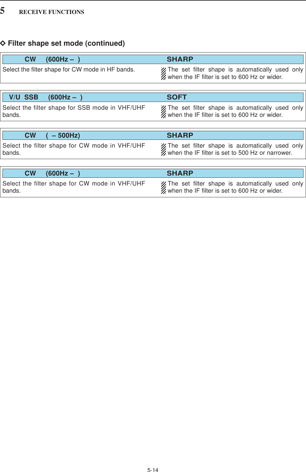
![5-135RECEIVE FUNCTIONSDRoofing filter selection The IC-R9500 has 3, 6 15 and 50 kHz roofing filters atthe 1st IF frequency. The roofing filter provides inter-ference reduction from nearby strong signals.qPush and hold [FILTER] for 1 sec. to enter filter setscreen.wSelect any mode except FM/WFM or P25 mode.ePush [F-6•ROOFING] to select the desired filterwidth from 50 kHz, 15 kHz (default), 6 kHz and3kHz.• Push and hold [F-4•DEF] for 1 sec. to select a defaultvalue.rPush [EXIT•SET] to exit filter set screen.DDSP filter shape The type of DSP filter shape for each SSB, SSB dataand CW can be selected independently from soft andsharp.qPush and hold [FILTER] for 1 sec. to enter filter setscreen.wSelect SSB, SSB data or CW mode.ePush [F-7•SHAPE] to select the desired filter shapefrom soft and sharp.rPush [EXIT•SET] to exit filter set screen.The filter shape can be set for each band (HF and50 MHz bands), mode, and passband width (CW only)independently as your default setting in filter shape setmode.DFilter shape set mode The type of DSP filter shape for each SSB and CWcan be selected independently from soft and sharp.qPush and hold [FILTER] for 1 sec. to enter filter setscreen.wPush and hold [F-7•SHAPE] for 1 sec. to enter filtershape set mode.ePush [F-1•Y] or [F-2•Z] to select the desired item.rRotate the main dial to select the filter shape fromsoft and sharp.tPush [EXIT/SET] to exit filter shape set mode.Select the filter shape for SSB mode in HF bands. The set filter shape is automatically used onlywhen the IF filter is set to 600 Hz or wider.HF SSB (600Hz – )SOFTSelect the filter shape for CW mode in HF bands. The set filter shape is automatically used onlywhen the IF filter is set to 500 Hz or narrower. CW ( – 500Hz)SHARP](https://usermanual.wiki/ICOM-orporated/284401.User-Manual-2/User-Guide-761725-Page-15.png)
![5-155RECEIVE FUNCTIONS■Noise blankerThe noise blanker eliminates pulse-type noise such asthe noise from car ignitions. The noise blanker is notavailable for FM/WFM or P25 mode.qPush [NB] several times to select the noise blankerfunction, NB1 or NB2, and OFF.• [NB] indicator above this switch lights green.• “NB1” or “NB2” appears on the display when either isON.wRotate [NB] control to adjust the noise blankerthreshold level.When using the noise blanker, received signals maybe distorted if they are excessively strong or thenoise type is other than pulsing. Turn the noiseblanker OFF, or rotate [NB] control to a shallow po-sition in this case.DNB set mode To deal with various type of noises, attenuation leveland noise width can be set in NB set mode. Two ofnoise blanker, NB1 and NB2, can be set indepen-dently.qTurn ON the desired noise blanker, NB1 or NB2.• When entering NB1 set mode, this step can be skipped.wPush and hold [NB] for 1 sec. to enter NB1 (or NB2)set mode.ePush [F-1•Y] or [F-2•Z] to select the desired item.rRotate the main dial to set the desired level or value. • Push and hold [F-4•DEF] for 1 sec. to select a defaultvalue.tPush [EXIT/SET] to exit NB1 (or NB2) set mode.[NB][NB] controlSet the noise attenuation level from 1 to 10.NB1 Depth8Set the noise pulse width from 1 to 100.NB1 Width40%• NB1 set mode Set the noise attenuation level from 1 to 10.NB2 Depth8Set the noise pulse width from 1 to 100.NB2 Width80%• NB2 set mode](https://usermanual.wiki/ICOM-orporated/284401.User-Manual-2/User-Guide-761725-Page-17.png)
![5-165RECEIVE FUNCTIONS■Noise reductionThe noise reduction function reduces random noisecomponents and enhances desired signals which areburied in noise. The DSP performs the random noisereduction function.qPush the [NR] to turn the noise reduction ON.• [NR] indicator above this switch lights green.wRotate the [NR] control to adjust the noise reductionlevel.ePush the [NR] switch to turn the noise reductionOFF.• [NR] indicator lights off.Setting the [NR] control too high can result in audiosignal masking or distortion. Set the [NR] control formaximum readability.■Notch functionThis receiver has auto and manual notch functions. The auto notch function uses DSP to automatically at-tenuates up to 3 beat tones, tuning signals, etc., even ifthey are moving. The manual notch can be set to at-tenuate a frequency via the [NOTCH1]/[NOTCH2] con-trols.The auto notch can be used in SSB, AM, FM and WFMmodes.The manual notch can be used in SSB, CW, FSK andAM modes.• Auto notch indication➥Push [ANF] to turn the auto notch function ON andOFF in FM, WFM, AM and SSB modes.• [ANF] indicator above this switch lights green.• “ ” appears when auto notch is in use.• Manual notch indication➥Push [NOTCH1] or [NOTCH2] to turn the manualnotch function ON and OFF, manual and OFF inAM, SSB, CW and FSK modes.• [NOTCH1]/[NOTCH2] indicators above these switcheslight green.• Push and hold [NOTCH1] or [NOTCH2] for 1 sec. to se-lect the notch filter width for manual notch from wide,middle and narrow.• Set to attenuate a frequency for manual notch via the[NOTCH1] or [NOTCH2] controls.• “ ” or “ ” appear when manual notch is in use.While tuning the manual notch, noise may be heard.This comes from the DSP unit and does not indicatean equipment malfunction.MN2MN1AN[ANF][NOTCH1] control [NOTCH2] control[NOTCH1] [NOTCH2][NR][NR] control](https://usermanual.wiki/ICOM-orporated/284401.User-Manual-2/User-Guide-761725-Page-18.png)
![5-175RECEIVE FUNCTIONS■Autotune functionThe Automatic tuning function tunes the displayed fre-quency (max. ±5 kHz) automatically when an off fre-quency signal is received. This function is active whilein AM, SSB or CW is selected.➥Push [AUTOTUNE] (AFC) to toggle the autotunefunction ON or OFF.• “ ” blinks when autotune function is acti-vate.• After 30 sec. has passed, the autotune function stopstuning automatically even it’s still off frequency.AppearsAUTO TUNE[AFC•AUTOTUNE]■AFC functionThe AFC stands for Automatic Frequency Control. TheAFC function tunes the displayed frequency automati-cally when an off-center frequency is received. It acti-vates in FM or WFM mode only.➥Push [AFC] to toggle the autotune function ON orOFF.• “AFC” appears when AFC function is active.The AFC limit can be set in the others set mode.While the AFC limit is ON, AFC stops tuning whenthe received frequency leaves the out of the fre-quency limit range. Appears[AFC•AUTOTUNE]](https://usermanual.wiki/ICOM-orporated/284401.User-Manual-2/User-Guide-761725-Page-19.png)
![6-2■About digital voice recordingThe IC-R9500 has two types of digital voice recorders.One is a regular voice recorder for which a continuouslong recording is available. And the other is a short recorder which temporarilystores the previous period. A maximum messagelength of 30 sec. can be recorded into a RAM.• Example— Regular recording• Example— Short recording• Playing back the all contents for short recording • Playing back the end of 5 sec.* for short recordingPush for 1 sec.(starts recording)Or, push for 1 sec.Push for 1 sec.(stops recording)Push momentarily(starts recording) Push momentarily(starts recording)Push momentarily.Push momentarily.15 sec.(default)30 sec. (max.) Not playing back Play back (5 sec.; default)3 sec.Push [REC] momentarily records the contents of the previous 15 sec.*When [REC] is pushed momentarily again within 15 sec.* from the last [REC] operation, all the contents between [REC] operations will be recorded.*The recording time period can be changed with “Short Rec Time” in voice set mode (p. 6-6).*The playing back time period can be changed with “Short Play Time” in voice set mode (p. 6-6).NOTE: The contents will be overwritten, and previous recorded contents are erased.NOTE: The recording time period differ depends on the recording sound quality and memory capacity.6VOICE RECORDER FUNCTIONS](https://usermanual.wiki/ICOM-orporated/284401.User-Manual-2/User-Guide-761725-Page-22.png)
![6-3■Recording received audioThis voice recorder records not only the receivedaudio, but also information such as operating fre-quency, mode, and the recording time for your futurereference.DRegular recordingqPush [EXIT/SET] several times to close a multifunc-tion screen, if necessary.wSelect the desired mode.ePush [F-2•VOICE] to call up the voice recorderscreen.• Push and hold [F-6•CF/USB] for 1 sec. once or twice toselect the CF card or USB-Memory, when USB memoryis Inserted.• The recording sound quality can be set in voice setmode. (p. 6-6)rPush and hold [REC] for 1 sec. to start recording.• The operating frequency, mode and current date/timeare programmed as the memory names automatically.tPush and hold [REC] for 1 sec. to stop recording.yPush [EXIT/SET] to exit the voice recorder screen.If you do not change any recording setting, you canstart or stop recording from the normal screen, justpush and hold [REC] for 1 sec.■Playing the recorded audioDRegular playingqPush [EXIT/SET] several times to close a multifunc-tion screen, if necessary.wPush [F-2•VOICE] to call up the voice recorderscreen.• Push and hold [F-6•CF/USB] for 1 sec. once or twice toselect the CF card or USB-Memory, when USB memoryis Inserted.ePush [F-1•Y] or [F-2•Z] to select the desired voicememory to playback.rPush [F-3•PLAY] to start playback.• “ ” indicators appear on the voice recorderscreen and display’s right edge, and the timer countsdown.• Push [F-1•<<<] when you want to rewind for 15 sec.• Push [F-2•<<] when you want to rewind for 5 sec.• Push [F-3•>>] when you want to fast forward for 5 sec.• Push [F-4•>>>] when you want to fast forward for 15 sec.• Push and hold above keys to continue rewinding or fastforwarding, respectively.• Push [F-5•PAUSE] when you want to pause playingback.tPush [F-6•STOP] to stop playback, if desired.• Playback is terminated automatically when all of therecorded contents in the channel are played.yPush [EXIT/SET] to exit the voice recorder screen.≈PLAYAppearCounts down[F-1•Y] [F-2•Z] [F-3•PLAY][EXIT/SET][REC][F-2•VOICE]6VOICE RECORDER FUNCTIONS](https://usermanual.wiki/ICOM-orporated/284401.User-Manual-2/User-Guide-761725-Page-23.png)
![6-4■Erasing the recorded contentsThe recorded contents can be erased independentlyby channel.qCall up the voice recorder screen.• Push and hold [F-6•CF/USB] for 1 sec. once or twice toselect the CF card or USB-Memory, when USB memoryis Inserted.wPush [F-1•Y] or [F-2•Z] to select the desired voicememory to be erased.ePush and hold [F-4•DEL] for 1 sec. to erase the con-tents.rPush [EXIT/SET] to exit the voice recorder screen.■Select the CF memory card or USB-MemoryThe voice recorder can record into CF memory card orUSB-Memory, when USB-Memory is inserted.qCall up the voice recorder screen.wPush and hold [F-6•CF/USB] for 1 sec. to select thedesired CF card or USB-Memory.eOperate the voice recorder as desired.rPush [EXIT/SET] to exit the voice recorder screen.[F-6•CF/USB][F-1•Y] [F-2•Z] [F-4•DEL]6VOICE RECORDER FUNCTIONS](https://usermanual.wiki/ICOM-orporated/284401.User-Manual-2/User-Guide-761725-Page-24.png)
![6-5■Short recordingTo record the receiving signal contents temporarily andimmediately, short recording is available. This shortrecording function records the 15 sec. (max.) of audioprior to when [REC] is pushed into RAM. Content isonly saved when the receiver’s power is ON and lostwhen power is removed.This short recording is useful when you miss hearingimportant information from the receiver, you can listento the important information once more. This functioncan be used while you are recording into CF memorycard or USB-Memory as regular recording.DRecording➥Push [REC] momentarily to save the previous15 sec. audio.• No indication appears.• The recordable time period can be set in voice set mode.(p. 6-6)DPlaying back• Short time play➥Push [PLAY] momentarily to play back the last5 sec. of the short recording audio.• “ ” indicator appears on the display’s right edge.• Playback is terminated automatically when all of therecorded contents, or after 5 sec.• The playback time period can be set in voice set mode.(p. 6-6)• Full time play➥Push and hold [PLAY] for 1 sec. to play back theshort recording audio for full time.• “ ” indicator appears on the display’s right edge.• Playback is terminated automatically when all of therecorded contents are played.≈PLAY≈PLAY[PLAY][REC]6VOICE RECORDER FUNCTIONS](https://usermanual.wiki/ICOM-orporated/284401.User-Manual-2/User-Guide-761725-Page-25.png)
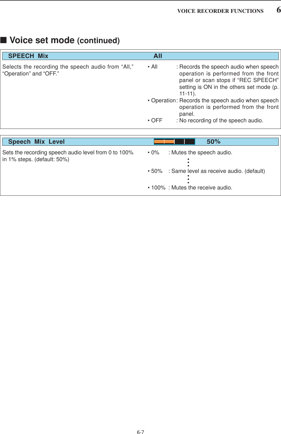
![6-6■Voice set modeSets the automatic monitor function, short play andnormal recording times for voice recorder.qPush [EXIT/SET] several times to close a multifunc-tion screen, if necessary.wPush [F-2•VOICE] to call up the voice recorderscreen.ePush [F-7•SET] to enter the voice set mode screen.rPush [F-1•Y] or [F-2•Z] to select the desired item.tRotate main dial to set the desired condition orvalue.• Push and hold [F-4•DEF] for 1 sec. to select the defaultcondition or value.yPush [EXIT/SET] to exit the voice set mode screen.[F-1•Y] [F-2•Z] [F-4•DEF] [EXIT/SET][F-7•SET] Main dial6VOICE RECORDER FUNCTIONSSet the desired time period for the short play back(when [PLAY] is pushed momentarily). • 3 to 10 sec. in 1 sec. steps can be set. (default: 5 sec.)Short Play Time5sSet the desired time period for one-touch recording(when [REC] is pushed momentarily). • 5 to 30 sec. in 1 sec. steps can be set. (default: 15 sec.)Short Rec Time15sSet the recording sound quality. The sampling ratesetting is expressed in samples per second, and de-termines the sound quality.Although a higher sampling rate provides a betterquality sound than a lower sampling rate, the file sizebecomes larger.• SQ1 (8kHz), SQ2 (12kHz), HQ1 (16KHz), HQ2(24kHz), SHQ (48kHz) can be set. (default: HQ1(16kHz))Sound Quality (Sampling Rate)HQ1(16kHz)Turns the recording control signal ON or OFF. (de-fault: OFF) • OFF : Continues recording even when receivedsignal disappears or squelch closes. (de-fault)• ON : Records only when received signal ap-pears or squelch opens and stops record-ing when received signal disappears orsquelch closes.REC RemoteOFF](https://usermanual.wiki/ICOM-orporated/284401.User-Manual-2/User-Guide-761725-Page-26.png)
![7-1MEMORY OPERATION Section 7■Memory channels ……………………………………………………… 7-2■Memory channel selection …………………………………………… 7-3DUsing the [M-CH]/[BANK] selectors ……………………………… 7-3DUsing the keypad …………………………………………………… 7-3■Memory channel programming ……………………………………… 7-4DProgramming in VFO mode ………………………………………… 7-4DProgramming in memory mode …………………………………… 7-4■Frequency transferring ………………………………………………… 7-5DTransferring in VFO mode ………………………………………… 7-5DTransferring in memory mode ……………………………………… 7-5■Memory names ………………………………………………………… 7-6DEditing (programming) memory names …………………………… 7-6■Memory clearing ………………………………………………………… 7-6■Memory list screen ……………………………………………………… 7-7DSelecting a memory channel using the memory list screen …… 7-7DConfirming programmed memory channels ……………………… 7-7DMemory bank set …………………………………………………… 7-8](https://usermanual.wiki/ICOM-orporated/284401.User-Manual-2/User-Guide-761725-Page-29.png)
![7-2■Memory channelsThe receiver has 1220 memory channels. Memorymode is very useful for quickly changing to often-usedfrequencies.All 1220 memory channels are tuneable which meansthe programmed frequency can be tuned temporarilywith the main dial, etc. in memory mode.memory chan-nel.7MEMORY OPERATIONMEMORYCHANNELRegular memorychannelsAuto write mem-ory channelsSkip memorychannelsScan edge mem-orychannelsMEMORYCHANNELNUMBER0–999(0–999)A00–A99(1000–1099)S00–S99(1100–1199)P0A–P9B(1200–1219)CAPABILITYFor normal use. Frequency, mode, tuningstep, name, P.AMP/ATT information and etc.can be programmed.Frequencies detected during auto memorywrite scan are memorized into this bank insequence. Mode and tuning step are writtenat the same time. Note that when “Auto MWScan Memory Clear” in scan set mode is setas “ON” and auto write scan is started, allmemories in this bank are cleared.Undesired signals such as from beacons, con-trol-coded signals, etc., can be programmedto be skipped during programmed scan andauto memory write scan. When [MW] ispushed and held for 1 sec. while scan ispaused, the displayed frequency is pro-grammed into this bank regardless of theselected bank.Memorize scan edge frequencies. 10 pairs ofscan edges (P0A to P9B) are programmable(upper and lower scan edges). Mode and tun-ing step are automatically equalized to the lastprogrammed channel in a pair.TRANSFERTO VFOYESYESYESYESOVER-WRITINGYESYESYESYESCLEARYESYESYESYES](https://usermanual.wiki/ICOM-orporated/284401.User-Manual-2/User-Guide-761725-Page-30.png)
![7-3■Memory channel selectionDUsing the [M-CH]/[BANK] selectors qPush [MEMO] to select memory mode.wRotate [BANK] to select the desired memory bank.eRotate [M-ch] to select the desired memory channel.rTo return to VFO mode, push [VFO].• Last operated VCO appears.• Or push numeral key (0–9) and [VCO] to return to thedesired VCO.✔Bank limit functionWhile rotating the [M-CH] selector, memory channelsare selectable in the current bank only (Bank limit ON);or selectable from all banks (Bank limit OFF). ➥Push and hold [MEMO] for 1 sec. to turn the banklimit function ON (default) or OFF.• “BANK” indicator appears or disappears.DUsing the keypadqPush [MEMO] to select memory mode.wPush the desired memory channel number using thekeypad.• Enter 0 to 999 to select the regular memory channels.• Enter 1000 to 1099 to select the auto write memorychannels A00 to A99. (Push “10” before entering mem-ory number instead of A.• Enter 1100 to 1199 to select the skip memory channelsS00 to S99. (Push “11” before entering memory numberinstead of S.• Enter 1200 to 1219 to select the scan edge channelsP0A to P9B.ePush [MEMO] to select the desired memory chan-nel.[EXAMPLE]To select the memory channel 3;- Push [3], then push [MEMO].To select the memory channel 520;- Push [5], [2], [0], then push [MEMO].To select the auto write memory channel A24;- Push [1], [0], [2], [4], then push [MEMO].To select the skip channel S65;- Push [1], [1], [6], [5], then push [MEMO].To select the scan edge channel P3B;- Push [1], [2], [0], [7], then push [MEMO].[MEMO] Keypad[MEMO] [M-CH][BANK]7MEMORY OPERATION1200 (P0A)1201 (P0B)1202 (P1A)1203 (P1B)1204 (P2A)1205 (P2B)1206 (P3A)1207 (P3B)1208 (P4A)1209 (P4B)1210 (P5A)1211 (P5B)1212 (P6A)1213 (P6B)1214 (P7A)1215 (P7B)1216 (P8A)1217 (P8B)1218 (P9A)1219 (P9B)](https://usermanual.wiki/ICOM-orporated/284401.User-Manual-2/User-Guide-761725-Page-31.png)
![7-47MEMORY OPERATION■Memory channel programmingMemory channel programming can be performed ei-ther in VFO mode or in memory mode.DProgramming in VFO modeqSet the desired frequency, operating mode and fil-ter width in VFO mode.wRotate [M-CH] (and [BANK]) to select the desiredmemory channel.• Memory list screen is convenient for selecting the de-sired channel.• Memory channel contents appear in the memory chan-nel readout (below the frequency readout).• “--.---.--” appears if the selected memory channel is ablank channel (and does not have contents).ePush and hold [MW] for 1 sec. to program the dis-played frequency, operating mode, etc., into thememory channel.DProgramming in memory modeqSelect the desired memory channel with [M-CH] inmemory mode.• Memory channel contents appear in the memory chan-nel readout (below the frequency readout).• “--.---.--” appears if the selected memory channel is ablank channel (and does not have contents).wSet the desired frequency and operating mode inmemory mode.• To program a blank channel, use direct frequency entrywith the keypad.ePush and hold [MW] for 1 sec. to program the dis-played frequency and operating mode into the mem-ory channel.[MW] [M-CH][BANK]Push for 1 sec.BeepBeepBeepRotate[EXAMPLE]: Programming 7.088 MHz/LSB into mem-ory channel 12.Push for 1 sec.BeepBeepBeepRotate[EXAMPLE]: Programming 21.280 MHz/USB into mem-ory channel 18.](https://usermanual.wiki/ICOM-orporated/284401.User-Manual-2/User-Guide-761725-Page-32.png)
![7-57MEMORY OPERATION■Frequency transferringThe frequency and operating mode in a memory chan-nel can be transferred to the VFO.Frequency transferring can be performed in either VFOmode or memory mode.DTransferring in VFO modeThis is useful for transferring programmed contents toVFO.qSelect VFO mode with [VFO].wSelect the memory channel to be transferred with[M-CH] (and [BANK]).• Memory list screen is convenient for selecting the de-sired channel.• Memory channel contents appear in the memory chan-nel readout (below the frequency readout).• “--.---.--” appears if the selected memory channel is ablank channel. In this case transferring is impossible.ePush and hold [M≈V] for 1 sec. to transfer the fre-quency and operating mode.• Transferred frequency and operating mode appear onthe frequency readout.DTransferring in memory modeThis is useful for transferring frequency and operatingmode while operating in memory mode.When you have changed the frequency or operat-ing mode in the selected memory channel:•Displayed frequency, mode and filter setting aretransferred.•Programmed frequency and mode in the memorychannel are not transferred, and they remain in thememory channel.qSelect the memory channel to be transferred with[M-CH] (and [BANK]) in memory mode.• And, set the frequency or operating mode if required.wPush and hold [M≈V] for 1 sec. to transfer the fre-quency and operating mode.• Displayed frequency and operating mode are transferredto the VFO.eTo return to VFO mode, push [VFO] momentarily.TRANSFERRING EXAMPLE IN VFO MODEOperating frequency : 21.320 MHz/USB (VFO)Contents of M-ch 16 : 14.018 MHz/CWTRANSFERRING EXAMPLE IN MEMORY MODEOperating frequency : 21.320 MHz/USB (M-ch 16)Contents of M-ch 16 : 14.018 MHz/CWPush for 1 sec.BeepBeepBeepRotatePush for 1 sec.BeepBeepBeepProgrammed contents appear.](https://usermanual.wiki/ICOM-orporated/284401.User-Manual-2/User-Guide-761725-Page-33.png)
![7-67MEMORY OPERATION■Memory namesAll memory channels (including scan edges) can betagged with alphanumeric names of up to 10 charac-ters each.Capital letters, small letters, numerals, some symbols(! # $ % & ¥ ? " ’ ` ^ + – ✱/ . , : ; = < > ( ) [ ] { } | _ ~@)and spaces can be used.DEditing (programming) memory namesqPush [EXIT/SET] several times to close a multifunc-tion screen, if necessary.wPush [F-4•MEMORY] to select memory list screen.eSelect the desired memory channel.rPush [F-4•NAME] to edit memory channel name.• A cursor appears and blinks.• Memory channel names of blank channels cannot beedited.tInput the desired character by rotating the main dialor by editing the keypad for number input.• Push [ABC] or [abc] to toggle capital and small letters.• Push [123] or [Symbol] to toggle numerals and symbols.• Push [F-1•Ω] or [F-2•≈] for cursor movement.• Push [F-3•DEL] to delete the selected character.• Push [F-4•SPACE] to input a space.• Using the receiver’s keypad, [0]–[9], can also enter nu-merals.yPush [EXIT/SET] to input and set the name.• The cursor disappears.uRepeat steps eto yto program another memorychannel’s name, if desired.iPush [EXIT/SET] to exit memory list screen.■Memory clearingAny unused memory channels can be cleared. Thecleared memory channels become blank channels.qSelect memory mode with [MEMO].wPush [F-4•MEMORY] to select memory list screen.eSelect the desired memory channel with [M-CH].rPush and hold [M-CL] for 1 sec. to clear the con-tents.• The programmed frequency and operating mode disap-pear.tTo clear other memory channels, repeat steps eand r.Push for 1 sec.BeepBeepBeep(CLR)[M-CL][F-1•Ω] [F-2•≈][F-4•SPACE][F-3•DEL]Keypad[ABC]/[abc] [123]/[Symbol]](https://usermanual.wiki/ICOM-orporated/284401.User-Manual-2/User-Guide-761725-Page-34.png)
![7-77MEMORY OPERATION■Memory list screenThe memory list screen simultaneously shows 9 mem-ory channels and their programmed contents. 15 mem-ory channels can be displayed in the wide memory listscreen.You can select a desired memory channel from mem-ory list screen.DSelecting a memory channel using the memory list screenqPush [EXIT/SET] several times to close a multifunc-tion screen, if necessary.wPush [F-4•MEMORY] to select memory list screen.• [F-7•WIDE] switches the standard and wide screens.eWhile pushing [F-1•ROLL], rotate the main dial toselect the desired memory channel.• [M-CH] can also be used.rPush [EXIT/SET] to exit memory list screen.• Memory list screenDConfirming programmed memory channelsqSelect memory list screen as described above.wWhile pushing [F-1•ROLL], rotate the main dial toscroll the screen.ePush [F-2•SET] to select the highlighted memorychannel, if desired.•“≈” appears beside the selected memory channel num-ber in the memory list screen and the selected memorychannel contents are displayed below the frequencyreadout.rPush [EXIT/SET] to exit memory list screen.Main dial[F-1•ROLL] [F-2•SET] [EXIT/SET][M-CH]Main dial[F-1•ROLL] [F-4•MEMORY] [EXIT/SET][F-7•WIDE]](https://usermanual.wiki/ICOM-orporated/284401.User-Manual-2/User-Guide-761725-Page-35.png)
![7-87MEMORY OPERATIONDMemory bank setSetting bank limit function for memory channel selec-tion, for memory scan can be set in bank set mode orprogramming bank name.qSelect memory list screen as described at previouspage.wPush and hold [F-6•EDT/BANK] for 1 sec. to displaythe memory bank set mode.ePush [F-1•Y] or [F-2•Z] to select the desired item.rRotate the main dial to set the desired setting. • Push and hold [F-4•DEF] for 1 sec. to select a defaultvalue.tPush [EXIT/SET] to return to memory list screen.Main dial[F-1•Y] [F-2•Z][EXIT/SET][F-6•EDT/BANK][F-4•DEF]Selects the bank limit function for memory channelselection from ON and OFF. (default: ON)BANK (Memory Channels)ONSelects the bank limit function for memory scan fromON and OFF. (default: ON)BANK (Memory Scan)ON• Programming bank namesCapital letters, small letters, numerals, some symbols(! # $ % & ¥ ? " ’ ` ^ + – ✱/ . , : ; = < > ( ) [ ] { } | _ ~@)and spaces can be used for bank name programming.qPush [F-1•Y] or [F-2•Z] to select the desired mem-ory bank.wPush [F-5•EDIT] to edit memory bank name.• A cursor appears and blinks.eInput the desired character by rotating the main dialor by editing the keypad for number input.• Push [ABC] or [abc] to toggle capital and small letters.• Push [123] or [Symbol] to toggle numerals and symbols.• Push [F-1•Ω] or [F-2•≈] for cursor movement.• Push [F-3•DEL] to delete the selected character.• Push [F-4•SPACE] to input a space.• Using the receiver’s keypad, [0]–[9], can also enter nu-merals.rPush [EXIT/SET] to input and set the name.• The cursor disappears.tRepeat steps qto rto program another memorybank’s name, if desired.yPush [EXIT/SET] to return to memory list screen.[F-1•Ω] [F-2•≈][F-4•SPACE][F-3•DEL]Keypad[ABC]/[abc] [123]/[Symbol]](https://usermanual.wiki/ICOM-orporated/284401.User-Manual-2/User-Guide-761725-Page-36.png)
![8-38SCANS■Preparation• ChannelsFor programmed scan: Program scan edge frequencies into scan edge mem-ory channels PxA and PxB.For∂F scan:Set the ∂F span (∂F scan range) in the scan screen.For memory scan: Program 2 or more memory channels except scanedge memory channels.For select memory scan: Designate 2 or more memory channels as select mem-ory channels. To designate the channel as a selectmemory channel, choose a memory channel, thenpush [F-3•SELECT] in the scan screen (memorymode) or in the memory list screen.• Scan resume ON/OFFYou can select the scan to resume or cancel when asignal is detected. Scan resume ON/OFF must be setbefore activating a scan. See p. 8-17 for ON/OFF set-ting and scan resume condition details.• Scan speedScan speed can be adjusted by [SPEED] controller.See p. 8-18 for details.• Squelch conditionSQUELCHCLOSEDSQUELCHOPENScan stops when a signal is detected.If you set ‘SCAN RESUME’ to ‘DELAY,’ thescan pauses according to [DELAY] controlwhen detecting a signal, then resumes.When a signal disappears while scan ispaused, scan resumes 2–20 sec. later.The scan continuesuntil it is stoppedmanually, and doesnot pause even if itdetects signals.Scan pauses oneach channel whenthe scan resume isON; not applicablewhen OFF.SCAN PROGRAMMEDSTARTS SCAN MEMORY SCANWITH■Voice squelch control functionThis function is useful when you don’t want unmodu-lated signals pausing or cancelling a scan. When thevoice squelch control function is activated, the receiverchecks received signals for voice components.If a receiver signal includes voice components, and thetone of the voice components changes within 1 sec.,scan pauses (or stops). If the received signal includesno voice components or the tone of the voice compo-nents does not change within 1 sec., scan resumes.➥While a phone mode (FM, WFM, SSB, AM) is se-lected, push [VSC] to switch the VSC (VoiceSquelch Control) function ON and OFF.• “VSC” appears when the function is activated.• The VSC function activates for any scan.• The VSC function resumes the scan on unmodu-lated signals, regardless of whether the scan re-sume condition is set to ON or OFF.[VSC]](https://usermanual.wiki/ICOM-orporated/284401.User-Manual-2/User-Guide-761725-Page-39.png)
![8-48SCANS■Scan set modeThis set mode is used to set the skip scan setting,memory clear condition for auto memory write chan-nels and appearing scan screen setting.qPush [F-5•SCAN] to select scan screen.wPush [F-7•SET] to select scan set mode.ePush [F-1•Y] or [F-2•Z] to select the desired item.rRotate the main dial to select the desired condition.• Push and hold [F-4•DEF] for 1 sec. to select the defaultsetting.tPush [EXIT/SET] to return to scan menu.[F-1•Y] [F-2•Z] [F-4•DEF] [EXIT/SET] Main dialSelect the skip scan function ON or OFF. • ON : Scan skips the programmed memory channelin the skip memory bank while scanning (de-fault)• OFF : Skip function OFFSKIP FunctionONSet the clearing condition for the auto memory writescan’s memories channels. • ON : Auto memory channels are cleared whenstarting the auto memory write scan.• [AUTO] Long Push: Auto memory channels are cleared whenpushing and holding [AUTO]. (default)• OFF : Auto memory channels must be cleared man-ually and auto memory write scan stops when100 channels (A00 to A99) are wrote.Auto MW SCAN Memory Clear[AUTO] Long PushSet the automatic scan screen ON function whenstarting a scan. • ON : When starting a scan, scan screen appearsautomatically. (default)• OFF : Scan screen does not appear until [F-5•SCAN] is pushed.Auto SCAN Screen (SCAN Start)ON](https://usermanual.wiki/ICOM-orporated/284401.User-Manual-2/User-Guide-761725-Page-40.png)
![8-58SCAN■Priority scanPriority scan monitors a specified frequency (the prior-ity channel) once every 1–16 sec. (programmable) dur-ing any operation, such as receiving, scanning otherchannels, etc. A total of 10 priority channels can beprogrammed.DSettingqPush [EXIT/SET] several times to close a multifunc-tion screen, if necessary.wPush [F-5•SCAN] to select scan setting screen.ePush [F-1•PRIO] once to enter priority channel se-lection.rRotate the main dial to select priority channel num-ber.• No.1 to No.9 are available.tPush [F-1•PRIO], then rotate main dial to select thedesired memory channel as priority channel.yPush [F-1•PRIO] to set the priority scan.uSet the desired VFO or memory channel.[F-1•PRIO] [EXIT/SET] Main dial [BANK]DPriority scan operationqPush [EXIT/SET] several times to close a multifunc-tion screen, if necessary.wSelect the desired VFO or memory channel.eSelect the desired operating mode when VFO is se-lected.• The operating mode can also be changed while scan-ning.rSet [SQUELCH] control open or closed.• See page 9-2 for squelch condition.tPush [PRIO] to start the priority scan.• “ ” blinks while scan screen is dis-played.• “PRIO” blinks while monitoring the priority channel.yTo cancel the scan, push [PRIO].• Pushing [F5•STOP] also cancels the scan.• Pushing [EXIT/SET] closes the scan screen, if displayed.PRIORITY SCANScan indicator and Priority scan number appearPriority channel indicator[EXIT/SET] [PRIO][SQUELCH]• Monitoring the Priority channelqPush and hold [PRIO] for 1 sec. to monitor thepriority channel.• “PRIO” blinks while monitoring the priority channel.wTo cancel the monitoring, push [PRIO].](https://usermanual.wiki/ICOM-orporated/284401.User-Manual-2/User-Guide-761725-Page-41.png)
![8-68SCANS■Programmed scanProgrammed scan searches for signals within a speci-fied frequency range, using the selected tuning step in-crements. The result is like ‘automatically’ rotating ofthe main dial.DSettingqPush [EXIT/SET] several times to close a multifunc-tion screen, if necessary.wPush [F-5•SCAN] to select scan setting screen.ePush [F-2•PROG] once to enter the programmedscan selection mode.rRotate the main dial to select the desired scanedges.• A pair of P0A and P0B to P9A and P9B are available.tPush [F-2•PROG] to enter the start edge frequencyprogramming, then edit the desired frequency usingthe keypad.yPush [F-2•PROG] to enter the end edge frequencyprogramming, then edit the desired frequency usingthe keypad.uPush [F-2•PROG] to enter the operating mode se-lection, then rotate main dial to select the desiredoperating mode.iPush [F-2•PROG] to enter the filter selection, thenrotate main dial to select the desired filter.oPush [F-2•PROG] to enter the tuning steps selec-tion, then rotate main dial or edit using the keypad toselect the desired tuning steps.!0 Push [F-2•PROG] to set the programmed scan.[F-2•PROG] [EXIT/SET] Main dialKeypad](https://usermanual.wiki/ICOM-orporated/284401.User-Manual-2/User-Guide-761725-Page-42.png)
![8-78SCANSDProgrammed scan operationqPush [EXIT/SET] several times to close a multifunc-tion screen, if necessary.wSelect the desired VFO or memory channel.eSelect the desired operating mode.• The operating mode can also be changed while scan-ning.rSet [SQUELCH] control open or closed.• See page 8-3 for squelch condition.tPush [PROG] to start the programmed scan.• Scan screen appears.• “ ” and decimal points blink whilescanning.• Push numeral key (0–9) to change to the other edges.yWhen the scan detects a signal, the scan stops,pauses or ignores it depending on the resume set-ting and the squelch condition.uTo cancel the scan, push [PROG].• Pushing [F5•STOP] also cancels the scan.• Pushing [EXIT/SET] closes the scan screen.iPush and hold [F-6•RECALL] for 1 sec. to recall thefrequency that is set before starting the scan, if de-sired.If the same frequencies are programmed into thescan edge memory channel PxA and PxB, pro-grammed scan does not start.✔For your convenienceTen programmed scans can be selected directly fromthe keypad. Then the scan starts immediately. ➥Push numeral key (0–9) then push [PROG] to startthe desired programmed scan.PROGRAM SCANScan indicator and Program scan number appear[EXIT/SET][SQUELCH] [PROG]](https://usermanual.wiki/ICOM-orporated/284401.User-Manual-2/User-Guide-761725-Page-43.png)
![8-88SCANS■∂F scan∂F scan scans a small range of frequencies around anoperating frequency. ∂F scan center frequency can beset as specific frequency or as the operating frequency.DSettingqPush [EXIT/SET] several times to close a multifunc-tion screen, if necessary.wPush [F-5•SCAN] to select scan setting screen.ePush [F-3•∂F] once to enter the center frequencysetting.rRotate the main dial to select the ∂F scan centerfrequency to fixed frequency or variable frequency.• Displayed frequency can be changed using the keypad.• When fixed frequency is selected, frequency appears.When variable frequency is selected,“---,---,--- MHz” ap-pears.tPush [F-3•∂F] then rotate the main dial to set the∂F span.• ±5 kHz, ±10 kHz, ±20 kHz, ±50 kHz, ±100 kHz,±500 kHz and ±1000 kHz are selectable.yPush [F-3•∂F] to set the ∂F scan.[F-2•:F] [EXIT/SET] Main dialD∂F scan operationqPush [EXIT/SET] several times to close a multifunc-tion screen, if necessary.wSelect the desired VFO or memory channel.eSelect the desired operating mode.• The operating mode can also be changed while scan-ning.rSet [SQUELCH] control open or closed.• See page 9-2 for squelch condition.tPush [∂F] to start the ∂F scan.• Scan screen appears.• “ ” and decimal points blink while scanning.• When the center frequency is fixed and the operatingfrequency exceeds the scanning range, ∂F scan jumpsto the fixed center frequency.yWhen the scan detects a signal, the scan stops,pauses or ignores it depending on the resume set-ting and the squelch condition.uTo cancel the scan, push [∂F].• Pushing [F5•STOP] also cancels the scan.• Pushing [EXIT/SET] closes the scan screen.iPush and hold [F-6•RECALL] for 1 sec. to recall thefrequency that was set before starting the scan, ifdesired.:F SCANScan indicator and ∂F scan indicator appear[EXIT/SET][SQUELCH] [:F]](https://usermanual.wiki/ICOM-orporated/284401.User-Manual-2/User-Guide-761725-Page-44.png)
![8-98SCANS■Fine programmed scan/fine ∂F scan operationIn fine scan (programmed or ∂F), the scan speed de-creases when the squelch opens, but the receiverkeeps scanning. The scanning tuning step shifts from50 Hz to 10 Hz when the squelch opens.qPush [EXIT/SET] several times to close a multifunc-tion screen, if necessary.wPush [F-5•SCAN] to select the scan screen.eSet for programmed scan or ∂F scan as describedat p.8-6 and p.8-8.rPush [PROG] or [∂F] to start a scan.• “ ” or “ ” and decimalpoints blink while scanning.tPush [FINE] to start a fine scan.• “ ” or “ ” blinks in-stead of “ ” or “ ,” respec-tively.yWhen the scan detects a signal, the scan speed de-creases but scan does not stop.uPush [PROG] or [∂F] to stop the scan; push [FINE]to cancel the fine scan.• Pushing [F5•STOP] also cancels the scan.• Pushing [EXIT/SET] closes the scan screen.iPush and hold [F-6•RECALL] for 1 sec. to recall thefrequency that is set before starting the scan, if de-sired.:F SCANPROGRAM SCANFINE :F SCANFINE PROGRAM SCAN:F SCANPROGRAM SCAN[EXIT/SET][SQUELCH] [:F][PROG] [FINE]](https://usermanual.wiki/ICOM-orporated/284401.User-Manual-2/User-Guide-761725-Page-45.png)
![8-108SCANS■Auto memory write scan operationAuto memory write scan operates in the same way asprogrammed scan. However, when a signal is re-ceived, the received frequency is automatically writteninto a memory channel in the auto write bank(A00–A99).qPush [EXIT/SET] several times to close a multifunc-tion screen, if necessary.wSelect the desired VFO or memory channel.eSelect the desired operating mode.• The operating mode can also be changed while scan-ning.rSet [SQUELCH] control open or closed.• See page 8-3 for squelch condition.tPush [AUTO] to start the auto memory write scan.• Selected programmed scan start.• Scan screen appears.• “ ” and decimal pointsblink while scanning.• Push numeral key (0–9) to change to the other edges.yWhen the scan detects a signal, the scan stops,pauses or ignores it depending on the resume set-ting and the squelch condition.• The received frequency is automatically written into ablank memory channel in the auto write bank.uTo cancel the scan, push [AUTO].• Pushing [F5•STOP] also cancels the scan.• Pushing [EXIT/SET] closes the scan screen.iPush and hold [F-6•RECALL] for 1 sec. to recall thefrequency that was set before starting the scan, ifdesired.✔For your convenienceTen auto memory write scans can be selected directlyfrom the keypad. Then the scan starts immediately. ➥Push numeral key (0–9) then push [AUTO] to startthe desired programmed scan.The memory clear setting of the auto write bank canbe selected from the starting auto memory writescan, by pushing and holding [AUTO], or manually.See scan set mode (p. 8-4) for Auto MW SCANMemory Clear details.AUTO MEMORY WRITE SCANScan indicator and Auto memory write scan number appear[EXIT/SET][SQUELCH] [AUTO]](https://usermanual.wiki/ICOM-orporated/284401.User-Manual-2/User-Guide-761725-Page-46.png)
![8-118SCANS■Memory scanAll memory channels (except skip channels) in the se-lected bank are scanned at up to 40 ch/sec.DSettingqPush [EXIT/SET] several times to close a multifunc-tion screen, if necessary.wPush [F-5•SCAN] to select scan setting screen.ePush [F-4•MEMO] once to enter the bank selection.rRotate the main dial to select the bank limit setting.• Selected bank number or OFF (Bank OFF) appears.tOr rotate [BANK] to select the other bank.yPush [F-4•MEMO], then rotate main dial to selectthe edge channel.uPush [F-4•MEMO], then rotate main dial to selectthe other edge channel.iPush [F-4•MEMO], then rotate main dial to selectthe desired select memory channel group for selectmemory scan.•‘★1’ to ‘★9’ and ‘ALL’ are available.oPush [F-4•MEMO] to set the memory scan.[F-4•MEMO] [EXIT/SET] Main dial [BANK]DMemory scan operationqPush [EXIT/SET] several times to close a multifunc-tion screen, if necessary.wSet the [SQUELCH] control open or closed.• See page 8-3 for squelch condition.ePush [MEMO] to start the memory scan.• Scan screen appears and memory mode is selected au-tomatically.• “ ” and decimal points blink duringmemory scan.rWhen the scan detects a signal, the scan stops,pauses or ignores it depending on the resume set-ting and the squelch condition.tTo cancel the scan, push [MEMO].• Pushing [F5•STOP] also cancels the scan.• Pushing [EXIT/SET] closes the scan screen.2 or more memory channels must be programmedfor memory scan to start.MEMORY SCAN[EXIT/SET] [MEMO][SQUELCH]](https://usermanual.wiki/ICOM-orporated/284401.User-Manual-2/User-Guide-761725-Page-47.png)
![8-128SCANSDProgramming the select memory scan settingqPush [EXIT/SET] several times to close a multifunc-tion screen, if necessary.wPush [F-4•MEMORY] to select memory list screen.eWhile pushing and holding [F-1•ROLL] or [F-2•SET],rotate the main dial to select the desired memorychannel.• [M-CH] (or [BANK]) control and direct keypad selectioncan be used.rPush and hold [F-3•SELECT] for 1 sec. to displaythe memory-select window.tRotate the main dial to select the desired selectmemory channel group.•★1 to ★9 are selectable.• Memory-select window yPush [F-3•SELECT] to set the select setting ON.• Push [F-3•SELECT] again to select the select settingOFF.uRepeat steps eto yto program another memorychannel as a select memory channel, if desired.• If you want to set a same select channel group, skipsteps rand t.iPush [EXIT/SET] to exit the memory list screen.DErasing the select scan settingqPush [EXIT/SET] several times to close a multifunc-tion screen, if necessary.wPush [F-4•MEMORY] to select memory list screen.ePush and hold [F-3•SELECT] for 1 sec. to displaymemory-select window.rRotate the main dial to select the desired selectmemory channel group to be erased.tPush and hold [F-2• ALL CLR] for 1 sec. to clear allselect scan settings.yPush [EXIT/SET] to exit the memory list screen.](https://usermanual.wiki/ICOM-orporated/284401.User-Manual-2/User-Guide-761725-Page-48.png)
![8-138SCANSDSelect memory scan operationSelect memory scan allows you to increase scan effi-ciency by searching for specified channels group only.qPush [EXIT/SET] several times to close a multifunc-tion screen, if necessary.wSet the [SQUELCH] control open or closed.• See page 8-3 for squelch condition.ePush [SEL] to start the select memory scan.• Scan screen appears and memory mode is selected au-tomatically.• “ ” and decimal points blinkduring select memory scan.• Push numeral key (0–9) to change to the other groups.rWhen the scan detects a signal, the scan stops,pauses or ignores it depending on the resume set-ting and the squelch condition.tTo cancel the scan, push [MEMO].• Pushing [F5•STOP] also cancels the scan.• Pushing [EXIT/SET] closes the scan screen.2 or more memory channels must be designated asselect memory channels, as well as the same selectscan number, for select memory scan to start.✔For your convenienceTen select memory scans can be selected directly fromthe keypad. Then the scan starts immediately. ➥Push numeral key (0–9) then push [SEL] to start thedesired select memory scan.Scan indicator and select memory group number appearSELECT MEMORY SCAN[EXIT/SET] [SEL][SQUELCH]](https://usermanual.wiki/ICOM-orporated/284401.User-Manual-2/User-Guide-761725-Page-49.png)
![8-148SCANSDMode select memory scan operationTo operate memory scan in a specific mode (ignoringother modes), the mode select memory scan is avail-able.qPush [EXIT/SET] several times to close a multifunc-tion screen, if necessary.wSet the [SQUELCH] control open or closed.• See page 8-3 for squelch condition.eSelect the desired operating mode.• The operating mode can also be changed while scan-ning.rPush [MODE] to start the mode select memoryscan.• Scan screen appears and memory mode is selected au-tomatically.• “ ” and decimal pointsblink during mode select memory scan.tWhen the scan detects a signal, the scan stops,pauses or ignores it depending on the resume set-ting and the squelch condition.yTo cancel the scan, push [MODE].• Pushing [F5•STOP] also cancels the scan.• Pushing [EXIT/SET] closes the scan screen.2 or more memory channels with same operatingmode must be programmed for mode select mem-ory scan to start.MODE SELECT MEMORY SCANScan indicator appears[EXIT/SET] [MODE][SQUELCH]](https://usermanual.wiki/ICOM-orporated/284401.User-Manual-2/User-Guide-761725-Page-50.png)
![8-158SCANS■Skip scanYou can set the selected memory channel as a skipchannel which is skipped during memory scan. Its fre-quency is also skipped during programmed and automemory write scans. This setting is useful to speed upthe scan speed.DSpecifying skip channelsqPush [EXIT/SET] several times to close a multifunc-tion screen, if necessary.wPush [F-4•MEMORY] to select memory list screen.eWhile pushing and holding [F-1•ROLL] or [F-2•SET],rotate the main dial to select the memory channel tobe specified as a skip channel.• [M-CH] (or [BANK]) control and direct keypad selectioncan be used.rPush [F-5•SKIP] to select the skip setting ON.• “SKIP” indicator appears.• Push [F-5•SKIP] again to select the skip setting OFF.tRepeat steps eto rto program another memorychannel as a skip channel, if desired.yPush [EXIT/SET] to exit the memory list screen.DProgramming skip frequencies (for programming scan)qStart programming scan as described on page 8-7.wWhen the scan pauses on an undesired signal, pushand hold [MW] for 1 sec.• The frequency is memorized into the skip bank as a skipfrequency.DSkip scan settingqPush [F-5•SCAN] to select scan screen.wPush [F-7•SET] to select scan set mode.ePush [F-1•Y] to select “SKIP Function.”rRotate the main dial to select the desired condition.• Push and hold [F-4•DEF] for 1 sec. to select the defaultsetting.tPush [EXIT/SET] to return to scan menu.[F-1•Y] [F-4•DEF] [EXIT/SET] Main dial[MW]](https://usermanual.wiki/ICOM-orporated/284401.User-Manual-2/User-Guide-761725-Page-51.png)
![8-168SCANS■Tone scanThe receiver can detect subaudible tones or the DTCScode in a received signal. By monitoring a signal that isbeing operated with tone or DTCS squelch function,you can determine the tone frequency or DTCS codenecessary to open a squelch.qSet the desired frequency or memory channel to bechecked for a tone frequency.wPush [FM] to select FM mode.ePush and hold [TONE] for 1 sec. to enter tone fre-quency screen.rPush [F-1•Y] or [F-2•Z] to check the tone squelchfrequency or DTCS code, respectively.tPush [F-6•T-SCAN] to start the tone scan.• “SCAN” blinks while scanning.yWhen the tone frequency is detected, the tone scanpauses.• The tone frequency is set temporarily on a memorychannel. Program into the memory channel to store thetone frequency permanently.• The decoded tone frequency is used for the tonesquelch frequency or DTCS squelch code.uTo stop the scan, push [F-6•T-SCAN].• Push and hold [F-4•DEF] for 1 sec. to select the defaultfrequency.iPush [EXIT/SET] to exit tone frequency screen.[EXIT/SET][FM][TONE][F-1•Y] [F-2•Z] [F-6•T-SCAN][F-4•DEF]](https://usermanual.wiki/ICOM-orporated/284401.User-Manual-2/User-Guide-761725-Page-52.png)
![8-178SCANS■Scan resume conditionScan pauses when finding a signal, and then resumesor is cancelled depending on the selected scan resumecondition. There are 3 resume conditions.• Scan resume OFFScan pauses until signal disappears, then resumesafter 2 sec.➥Push [OFF] to set the scan pause timer to OFF.• Scan resume indicator above this switch lights green.• Scan resume ON with specified time periodScan pauses for the adjusted delay period after re-ceiving a signal, then resumes. When the received sig-nal disappears, scan resumes after 2 to 20 sec.➥Push [DELAY] to set the scan pause timer to speci-fied time period according to [DELAY] control. (Seenext page for setting scan delay.)• Scan resume indicator above this switch lights green.• Scan delay time can be set 2 to 20 sec.• Scan cancelScan is cancelled when a signal is found during scan.➥Push [] to set the scan pause timer to infinity (scancancel).• Scan resume indicator above this switch lights green.Signal no signalscanning scan is cancelled receiving a signal no signalScanSignal no signalscanning scanningpausingdelay timereceiving a signal no signalScanSignal no signalscanning scanningpausing2 sec.receiving a signal no signalScan[OFF] ['][DELAY]](https://usermanual.wiki/ICOM-orporated/284401.User-Manual-2/User-Guide-761725-Page-53.png)
![8-188SCANS■Scan speed➥Rotate [SPEED] to adjust the scan speed.[SPEED]■Scan delay➥Rotate [DELAY] to adjust the scan pause time whenthe scan resume setting is set to ‘DELAY.’• Scan delay time can be set 2 to 20 sec.[DELAY]](https://usermanual.wiki/ICOM-orporated/284401.User-Manual-2/User-Guide-761725-Page-54.png)
![9-29OTHER FUNCTIONS■Voice synthesizer operationThe IC-R9500 has a built-in voice synthesizer to an-nounce the frequency, mode, etc. (S-meter level canalso be announced—p. 11-10) in clear, electronically-generated voice, in English (or Japanese).➥Push [SPCH] to announce the currently selectedfrequency, etc.• Push [SPCH] for 1 sec. to additionally announce the se-lected mode.➥Pushing a mode switch also announces the appro-priate mode. (p. 11-11)The output level of the voice synthesizer can be ad-justed in level set mode. (p. 11-6)■Lock functionThe IC-R9500 has two kinds of lock functions: dial lockand panel lock. The dial lock function locks only themain dial, and panel lock function locks all front paneloperation.DDial lock functionThe dial lock function prevents frequency changes byaccidental movement of the tuning dial. The lock func-tion electronically locks the dial.➥Push [LOCK] to toggle the dial lock function ON orOFF.• The [LOCK] indicator lights orange when the dial lockfunction is in use.DPanel lock functionTo prevent accidental frequency changes and unnec-essary function access, use the panel lock function.This function is also available with display sleep mode➥Push [PANEL LOCK] to toggle the panel lock func-tion ON or OFF.• The [PANEL LOCK] indicator lights green when thepanel lock function is in use.➥Push and hold [PANEL LOCK] for 1 sec. to turn thepanel lock with display sleep function ON.• Pushing [PANEL LOCK] turns OFF the function.• The [PANEL LOCK] indicator lights green and the dis-play turns OFF when the sleep function is in use.[PANEL LOCK] indicator[PANEL LOCK][LOCK] indicator[LOCK][SPCH]](https://usermanual.wiki/ICOM-orporated/284401.User-Manual-2/User-Guide-761725-Page-56.png)
![9-39OTHER FUNCTIONS■Dial click functionThe IC-R9500 can turn the dial click function ON andOFF. And the auto dial click setting is also available inthe others set mode (p. 11-12).➥Push and hold [1/4] for 1 sec. to turn the dial clickfunction ON and OFF manually.• “CLICK” appears.[1/4]■Antenna selectionThe IC-R9500 has 3 antenna connectors for bandsbelow 30 MHz which are [HF ANT1], [HF ANT2] and[ANT1/HF ANT3]. And antenna control voltage is alsooutput from [ANT SEL] connector for using externalpreamplifier or antenna selector.For each operating band the IC-R9500 covers, thereis a band memory which can memorize a selected an-tenna. When you change the operating frequency be-yond a band, the previously used antenna is automat-ically selected (see left) for the new band. This functionallows automatic switching of 3 separate antennas forHF bands operation.After an antenna has been selected for use (by push-ing [ANT]), the antenna is automatically selectedwhenever that band is used.[EXAMPLE]: a 3.5/7 MHz antenna is connected to[HF ANT1], a 14/18 MHz antenna is connected to [HFANT2], a 24/28 MHz antenna is connected to [HFANT3]. After each antenna is selected, an antenna isautomatically selected when changing bands.• Antenna selection➥Push [ANT] to select the antenna from “ANT HF 1,”“ANT HF 2” and “ANT HF 3.”• The antenna indicator turns ON when other than defaultantenna (ANT1) is selected.➥Push and hold [ANT] for 1 sec to turn the antennacontrol voltage ON and OFF from [ANT SEL] con-nector.• When it’s ON, “★” appears. Then the receiver output13.8 V/100 mA max. from [ANT SEL] connector.[ANT]IC-R95001150~3335MHz帯 30~1150MHz帯 HF ANT1HF ANT2HF ANT3](https://usermanual.wiki/ICOM-orporated/284401.User-Manual-2/User-Guide-761725-Page-57.png)
![10-2■Time set modeThe IC-R9500 has a built-in calendar and 24-hourclock with daily power ON/OFF timer functions. Beforeoperating these timer functions, set the current dateand time.qPush [EXIT/SET] to close multifunction screen, ifnecessary.wPush [F-7•SET] to select set mode menu screen.ePush [F-4•TIME] to select time set mode.rPush [F-1•Y] or [F-2•Z] to select the desired item.tRotate the main dial to set or select the desiredvalue or condition.yPush [EXIT/SET] to exit time set mode.[F-1•Ω] [F-2•≈]Main dial[EXIT/SET][F-4•DEL][F-5•EDIT]/[F-5•SET][ABC]/[abc][123]/[Symbol][F-3•Ω≈]10 CLOCK AND TIMERSSets the date. zPush [F-3•Ω≈] to select between the year and themonth/day, then rotate the main dial to select them.• The date setting and “DATE-set Push [SET]” indicationblink.xPush [F-5•SET] to set the date.Date2000 – 1 – 1 ( Sat )Sets the local time. zRotate the main dial to set the local time.• The time setting and “TIME-set Push [SET]” indicationblink.xPush [F-5•SET] to set the time.Time (Now)1:23Turns the clock 2 display ON and OFF.The clock 2 is convenient to indicate UTC or anothercountry’s local time, etc.• ON : Clock 2 is displayed below the local time dis-play.• OFF : The clock 2 is not displayed.CLOCK2 FunctionONSets the desired offset time period for clock 2 within–24:00 to +24:00 in 5 min. steps.• Push and hold [F-4•DEF] for 1 sec. to select the defaultvalue.CLOCK2 Offset0:00Sets the desired 3-character name for clock 2.Capital letters, small letters, numerals, some symbols(! # $ % & ¥ ? " ’ ` ^ + – ✱/ . , : ; = < > ( ) [ ] { } | _ ~@)and spaces can be used.zPush [F-5•EDIT] to select the name edit condition.• The cursor under the 1st character blinks.xPush [ABC], [abc], [123] or [Symbol] to select thecharacter group, then rotate the main dial to selectthe character.• Push [ABC] or [abc] to toggle capital and small letters.• Push [123] or [Symbol] to toggle numerals and sym-bols.• Push [F-1•Ω] or [F-2•≈] for cursor movement.• Push [F-3•DEL] to delete the selected character.• Push [F-4•SPACE] to input a space.• Using the receiver’s keypad, [0]–[9], can also enter nu-merals.cPush [EXIT/SET] to set the name.CLOCK2 NameUTC](https://usermanual.wiki/ICOM-orporated/284401.User-Manual-2/User-Guide-761725-Page-60.png)
![10-3■Daily timer settingThe receiver turns power ON and/or OFF automaticallyat the specified day and time, with the specified fre-quency settings.qPush [EXIT/SET] several times to close multifunc-tion screen, if necessary.wPush [TIMER] for 1 sec. to select timer set screen.ePush one of [F-1•TIMER1] to [F-5•TIMER5] to se-lect the desired timer.rRotate the main dial to select the timer action ONand OFF.tPush [F-2•≈] to select the “DAY” cell, then rotate themain dial to select the desired day of the week.• Select “– – –” not to specify daily operation and activatethe timer every day.• Once a day of the week is selected, push [F-4•CLR] for1 sec. to select “– – –.” yPush [F-2•≈] to select the “REPEAT” cell, then ro-tate the main dial to select the repeat function ONor OFF.• ON : The timer functions every selected day of theweek. (repeats)• OFF : The timer does not repeat.uPush [F-2•≈] to select the “ON” cell, then rotate themain dial to set the desired receiver power ON time.• When using power OFF timer only, push [F-4•CLR] for1 sec. to select “– – –.” iPush [F-2•≈] to select the “OFF” cell, then rotate themain dial to set the desired receiver power OFFtime.• When using power ON timer only, push [F-4•CLR] for1 sec. to select “– – –.” oPush [F-2•≈] to select the “MAIN” cell, then rotatethe main dial to select the desired memory channelnumber in the main readout.• If using the currently set VFO condition in main readout,push [F-4•CLR] for 1 sec. to select “– – –.” !0 Push [F-7•SET] to set the timer.• The timer indicator above [TIMER] switch lights green.!1 Repeat steps eto !0 to set other timers, if desired.!2 Push [EXIT/SET] to exit timer set screen.[EXIT/SET][F-4•TIMER4]/[F-4•CLR][F-3•TIMER3][TIMER][F-7•SET][F-1•TIMER1]/[F-1•Ω][F-2•TIMER2]/[F-2•≈]Main dial10CLOCK AND TIMERS](https://usermanual.wiki/ICOM-orporated/284401.User-Manual-2/User-Guide-761725-Page-61.png)
![10-4■Setting sleep timerThe sleep timer turns the receiver power OFF auto-matically after a set period. The timer can be set to5–120 min. in 5 min. steps.The sleep timer function counts the ‘minute’ unit,and does not count the ‘second’ unit. For example,when the sleep timer is started at 12:00 59, first oneminute past for just 1 sec. That is way it has max.59 sec. an error. This is normal, not a malfunction.qPush [EXIT/SET] several times to close a multifunc-tion screen, if necessary.wPush [TIMER] for 1 sec. to select timer set screen.ePush [F-7•SLEEP] to select the sleep timer set con-dition.• “– – –” blinks.rSet the desired time period using the main dial.• “TIMER–set Push [SET]” blinks.• Push [F-4•CLR] to select “– – –” to cancel the setting.tPush [F-7•SET] to set the time.• Push [EXIT/SET] to cancel the setting.• The timer indicator above [TIMER] switch lights green.yPush [EXIT/SET] to exit timer set screen.uThe receiver emits 10 beeps and turns OFF afterthe sleep timer period elapses.• The timer indicator blinks while beeping.• Push [TIMER] momentarily to cancel the sleep timer, ifdesired.■Timer operationqPreset the daily timer as described previously.wPush [TIMER] momentarily to turn the timer functionON.• The timer indicator above this switch lights green whenthe timer function is ON.ePush and hold [POWER] for 1 sec. to turn the powerOFF.• The timer indicator lights continuously.rWhen the set time arrives, the power is automati-cally turned ON.tThe receiver emits 10 beeps and turns OFF afterthe power-off period elapses.• The timer indicator blinks while beeping.• Push [TIMER] momentarily to cancel the sleep timer, ifdesired.The timer action in timer set screen must be turnedON to enable the timer operation, described above“Setting sleep timer” steps r.[TIMER] [POWER][EXIT/SET][TIMER] Main dial[F-4•CLR][F-7•SLEEP]/[F-7•SET]10 CLOCK AND TIMERS](https://usermanual.wiki/ICOM-orporated/284401.User-Manual-2/User-Guide-761725-Page-62.png)