ICOM orporated 284401 Scanning Receiver User Manual IC R9500 manual
ICOM Incorporated Scanning Receiver IC R9500 manual
UserManual.wiki
>
ICOM orporated
>
284401 User Manual
>
User Manual 3
Contents
1.
User Manual 1
2.
User Manual 2
3.
User Manual 3
User Manual 3
Navigation menu
Upload a User Manual
Namespaces
Wiki Guide
HTML
PDF
Info
Views
User Manual
Discussion / Help
Navigation
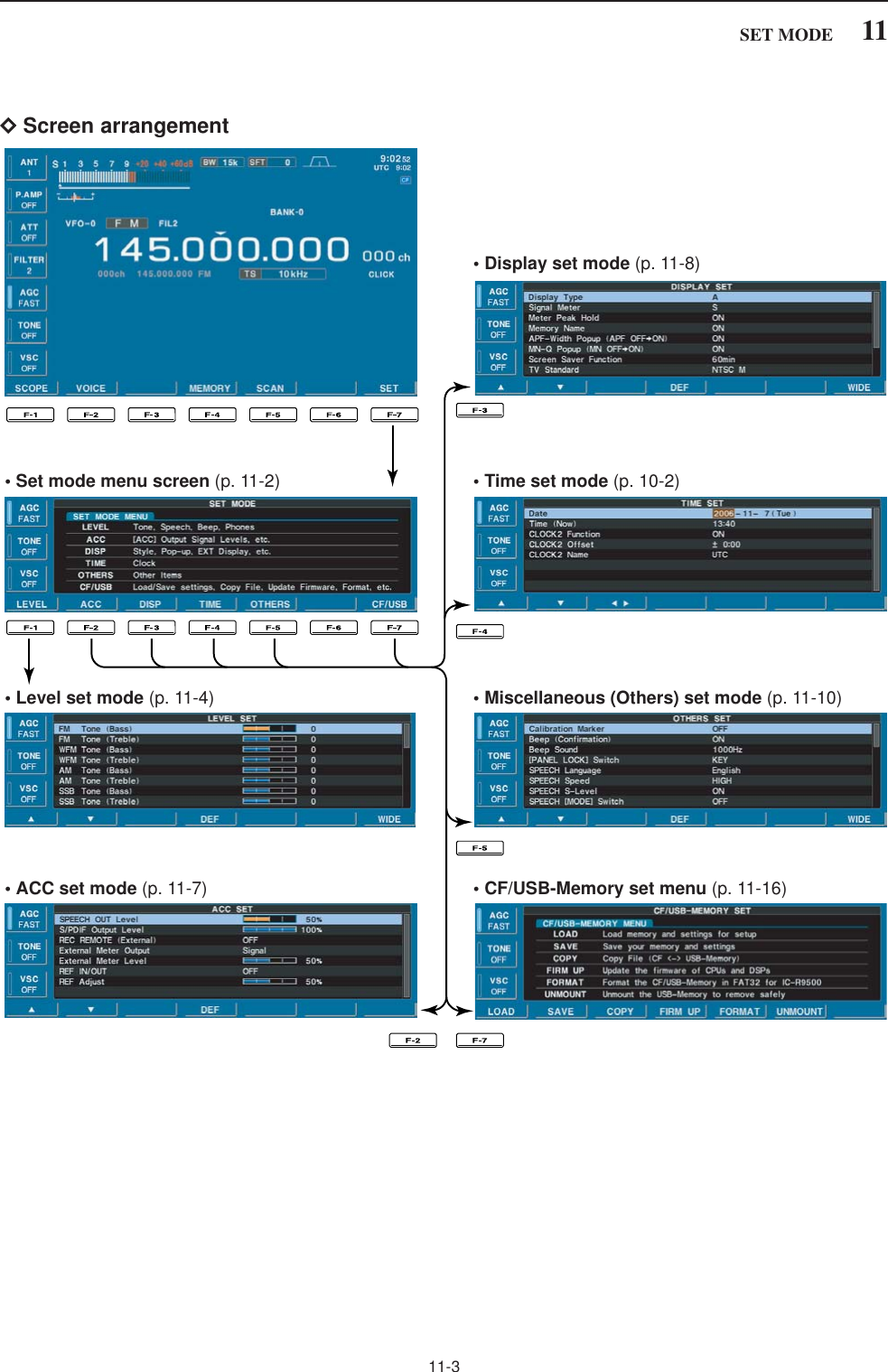
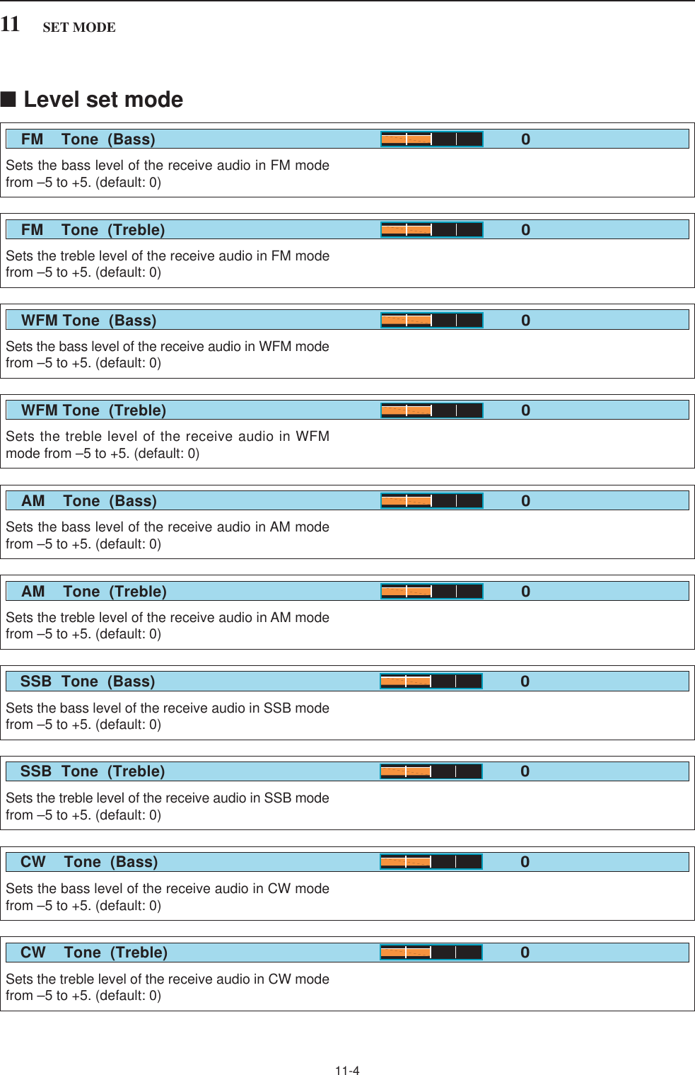
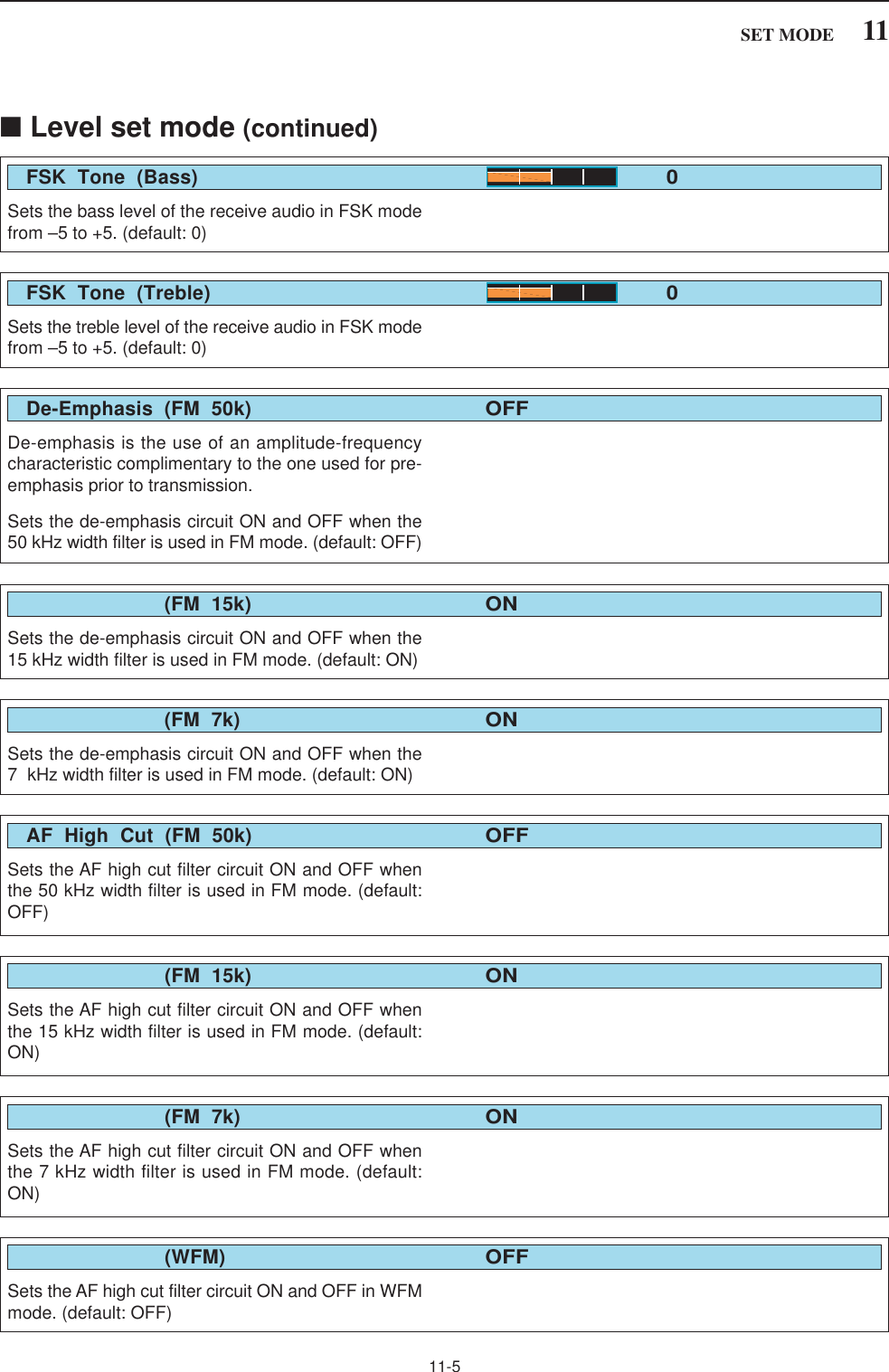
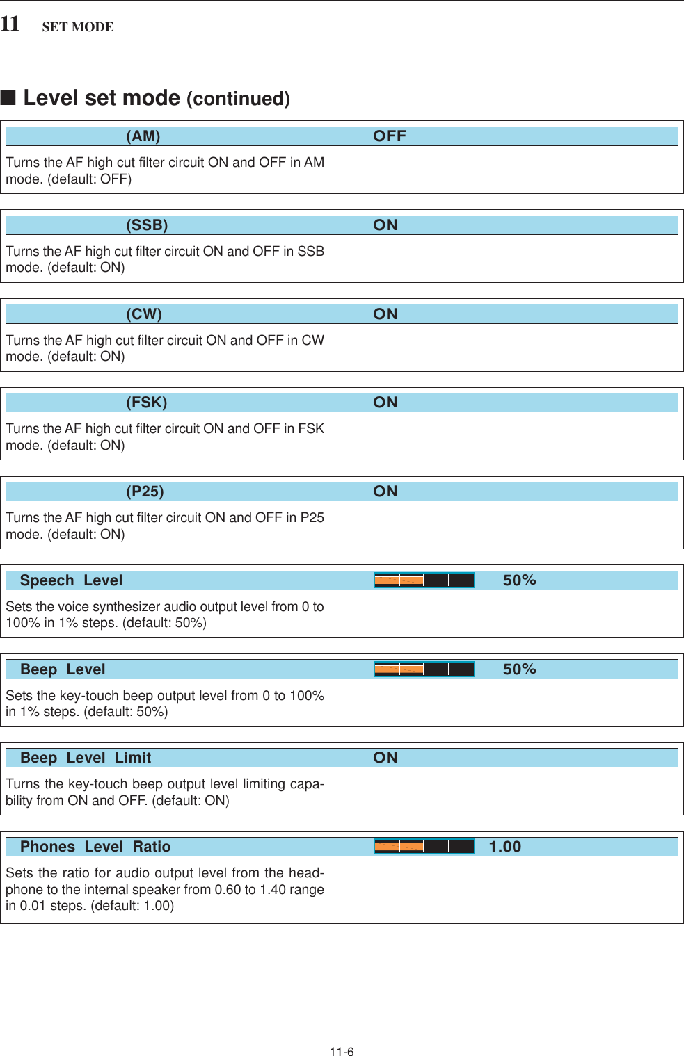
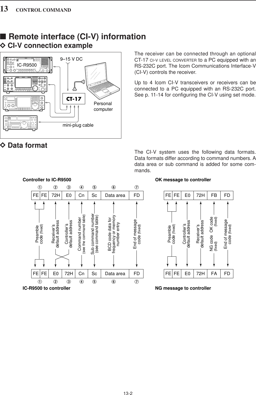
![11-2■Set mode descriptionSet mode is used for programming infrequentlychanged values or conditions of functions. The IC-R9500 has a level set mode, display set mode, timerset mode, accessory set mode, others set mode andCF/USB-Memory set mode.DSet mode operationqPush [EXIT/SET] several times to close a multi-function screen, if necessary.wPush [F-7•SET] to select set mode menu screen.• Pushing and holding [EXIT/SET] for 1 sec. also selectsset mode menu screen.ePush [F-1•LEVEL], [F-2•ACC], [F-3•DISP], [F-4•TIME], [F-5•OTHERS] or [F-7•CF/USB] toenter the desired set mode.rFor level, accessory, display and others set mode,push [F-7•WIDE] to toggle wide and normal screen.tPush [F-1•Y] or [F-2•Z] to select the desired item,then rotate main dial to adjust/select the desiredvalue or condition.• Pushing [F-3•Ω≈] operation may be necessary forsome items.yPush [EXIT/SET] twice to exit set mode.[EXIT/SET] Main dial[F-1•LEVEL][F-2•ACC] [F-3•DISP][F-5•OTHERS][F-4•TIME][F-7•CF/USB]11 SET MODE](https://usermanual.wiki/ICOM-orporated/284401.User-Manual-3/User-Guide-761726-Page-2.png)
![11-711SET MODE■ACC set mode Sets the speech audio output level from [SPEECHOUT] from 0 to 100% in 1% steps.• Outputs approx. 200 mV at 50% (default) setting.SPEECH OUT Level50%Sets the desired output level of [S/P DIF OUT], from 0to 100% in 1% steps. (default: 100%)S/PDIF Output Level100%Sets the output level for an external meter indicationfrom 0 to 100% range in 1% steps.• Approx. 2.5 V at 50% (default) setting for full-scale indica-tion. (4.7 kimpedance)External Meter Level50%External Meter Level50%Selects the receiver’s reference signal condition fromIN, OFF and OUT. • IN : Use an external reference signal for the IC-R9500.• OFF : No input or output of the reference signal. (default)• OUT : Outputs the IC-R9500 reference signal toexternally connected equipment(s) for theirreference.NOTE: If the applied reference signal is off-fre-quency, or no signal is applied with “IN” selection,the IC-R9500 will not work properly. Select “OFF”or “OUT” then reboot the IC-R9500.External Meter Level50%Reference IN/OUTOFFAdjusts the internal reference frequency within 0 to100% in 1% steps during frequency calibration. NOTE: Default setting is different for each receiver.REF Adjust40%Turns the control signal of external equipment outputcapability ON and OFF. (default: OFF) • OFF : No signal output from [REC REMOTE]jacks. (default)• ON : The [REC REMOTE] jacks shorts toground when receiving a signal or thesquelch is open.REC Remote (External)OFFSelects the squelch condition output for an externalmeter indication from pin 8 of [ACC]. • Signal : Outputs the receiving signal strengthlevel during receiving. (default)• Signal+SQL: Outputs the receiving signal strengthlevel during receiving and outputssquelch open/close condition.External Meter OutputSignal](https://usermanual.wiki/ICOM-orporated/284401.User-Manual-3/User-Guide-761726-Page-7.png)
![Selects the desired display type from A and B. (default: A)Display TypeA■Display set mode Selects the desired signal meter type from “S,” “dBµ,”“dBµ[EMF]” and “dBm.”(default: S)Signal MeterSTurns the meter peak hold function ON or OFF. (default: ON)This function is used for the bar meter only.Meter Peak HoldONSets the memory name indication, during memorymode operation, ON and OFF. (default: ON) • ON : The programmed memory name is displayedabove the frequency indication.• OFF : No memory name is displayed even a mem-ory name is programmed.Memory NameON11-811 SET MODESelects the pop-up indication of the APF filter widthON and OFF when the APF function is turned ON.(default: ON)APF-Width Popup (APF OFF➞ON)ONSelects the pop-up indication of the received ID inP25 mode ON and OFF. (default: ON) • ON (Hex): The received ID code (hexadecimal indi-cation) is displayed when an ID code isreceived.• ON (Dec): The received ID code (decimal indication)is displayed when an ID code is received.(default)• OFF : No ID code is displayed when an ID codeis displayed.P25 RX ID PopupON (Dec)Selects the pop-up indication of the notch filter widthON and OFF when the notch filter is turned ON. (default: ON)MN-Q Popup (MN OFF➞ON)ONTurns the screen saver function ON (15, 30 or 60 min-utes) and OFF. (default: 60 min.) The screen saver will activate when no operation isperformed for the selected time period to protect theLCD from “burn-in.”Screen Saver Function60minNOTE: “Display set (Video) mode” is described on page 11-24.](https://usermanual.wiki/ICOM-orporated/284401.User-Manual-3/User-Guide-761726-Page-8.png)
![11-911SET MODESets the introductory text, up to 10-character long,displayed in the opening screen.Capital letters, small letters, numerals, some symbols(– / . @) and spaces can be used.zPush [F-5•EDIT] to select the name edit condition.• The cursor under the 1st character blinks.xPush [ABC], [abc], [123] or [Symbol] to select thecharacter group, then rotate the main dial to selectthe character.• Push [ABC] or [abc] to toggle capital and small letters.• Push [123] or [Symbol] to toggle numerals and sym-bols.• Push [F-1•Ω] or [F-2•≈] for cursor movement.• Push [F-3•DEL] to delete the selected character.• Push [F-4•SPACE] to input a space.• Using the receiver’s keypad, [0]–[9], can also enter nu-merals.cPush [EXIT/SET] to set the name.Opening CommentSelect “ON” when the external display is connected. (default: OFF)• At least 800×600 pixel resolution is required for the dis-play.External DisplayOFFSelects the suitable pulse level for the connected ex-ternal display from H and L. (default: H)External Display Sync PulseHTurns the opening message screen indication capa-bility ON and OFF. (default: ON)Opening MessageON■Display set mode (continued)](https://usermanual.wiki/ICOM-orporated/284401.User-Manual-3/User-Guide-761726-Page-9.png)
![11-1011 SET MODE■Others set mode This item is used for a simple frequency check of thereceiver. (default: OFF)See p. 12-5 for calibration procedure.NOTE: Turn the calibration marker OFF afterchecking the frequency of the receiver.Calibration MarkerOFFA beep sounds each time a switch is pushed to con-firm it. This function can be turned OFF for silent op-eration. (default: ON)The beep output level can be set in level set mode.(p. 11-6)Beep (Confirmation)ONSets the desired key-touch beep sound frequencyfrom 500 to 2000 Hz in 10 Hz steps. (default:1000 Hz)Beep Sound1000HzSelects the Panel lock function activity from “ALL” and“KEY.” (default: ALL)[PANEL LOCK] SWITCHALLSelects the speech language from English and Japan-ese. (default: English)SPEECH LanguageEnglishSelects the speech speed from HIGH (faster) andLOW (slower). (default: HIGH)SPEECH SpeedHighThe IC-R9500 speech processor has frequency,mode and signal level announcement. Signal level an-nouncement can be deactivated if desired.(default: ON)When “OFF” is selected, the signal level is not an-nounced.SPEECH S-LevelON](https://usermanual.wiki/ICOM-orporated/284401.User-Manual-3/User-Guide-761726-Page-10.png)
![11-1111SET MODESelects the frequency speech capability when scanstops; ON or OFF.NOTE: Output jacks are selected depending on“SPEECH Mix” settings. See the combination of“REC SPEECH” and “SPEECH Mix” settings in thetable below.• ON : The frequency is announced through the[REC OUT]/[LINE OUT] or [SPEECH OUT]when scan stops.• OFF : No speech audio outputs when scan stops.REC SPEECHOFFSelects the speech audio output from the [REC OUT]or [LINE OUT].NOTE: See the combination of “REC SPEECH”and “SPEECH Mix” settings below table.• All : Outputs the speech audio when speechoperation is performed from the frontpanel or depends on above “RECSPEECH” setting. (default)• Operation: Outputs the speech audio when speechoperation is performed from the frontpanel.• OFF : No speech audio outputs from [RECOUT] or [LINE OUT].SPEECH MixAllSelects the operating mode speech capability when amode switch is pushed; ON or OFF. (default: OFF)When “ON” is selected, the selected operating modeis announced when a mode switch is pushed.SPEECH [MODE] SWITCHOFF■Others set mode (continued)Switch setting Speech operation from front panel Scan stopsRECSPEECHOFFONSPEECHMixAllOperationOFFAllOperationOFFInternalSpeaker✔✔–✔✔–[REC OUT] /[LINE OUT]✔✔–✔✔–[SPEECH OUT]✔✔✔✔✔✔InternalSpeaker–––✔✔–[REC OUT] /[LINE OUT]–––✔––[SPEECH OUT]–––✔✔✔• Combination of REC SPEECH and SPEECH Mix settings](https://usermanual.wiki/ICOM-orporated/284401.User-Manual-3/User-Guide-761726-Page-11.png)
![11-1411 SET MODESets the CI-V data transfer rate. 300, 1200, 4800,9600, 19200 bps and “Auto” are available. (default:Auto)When “Auto” is selected, the baud rate is automati-cally set according to the data rate of connected con-troller.CI-V Baud RateAuto■Others set mode (continued)Transceive operation is possible with the IC-R9500connected to other Icom transceivers or receivers.When “ON” is selected, changing the frequency, op-erating mode, etc. on the IC-R9500 automaticallychanges those of connected transceivers (or re-ceivers) and vice versa.CI-V TransceiveONSelect [RS-232C] connector output data format fromCI-V and Decode. • CI-V : Outputs data in CI-V format. (default)• Decode : Outputs decoded contents in ASCII codeformat.RS-232C FunctionCI-VSelects data transmission speed (Baud rate) when“Decode” is selected in “RS-232C Function” above;settings are 300, 1200, 4800, 9600 and 19200 bps. (default: 9600)Decode Baud Rate9600To distinguish equipment, each CI-V transceiver or re-ceiver has its own Icom standard address in hexa-decimal code. The IC-R9500’s address is 72h.When 2 or more IC-R9500’s are connected to an op-tional CT-17 CI-V LEVEL CONVERTER, rotate the main dialto select a different address for each IC-R9500; therange is 01h to 7Fh.CI-V Address72hSelects the connected keyboard type from Japanese,English, United Kingdom, French, French (Canadian),German, Portuguese, Portuguese (Brazilian), Span-ish, Spanish (Latin American) and Italian. (default: English)Keyboard TypeEnglish](https://usermanual.wiki/ICOM-orporated/284401.User-Manual-3/User-Guide-761726-Page-14.png)
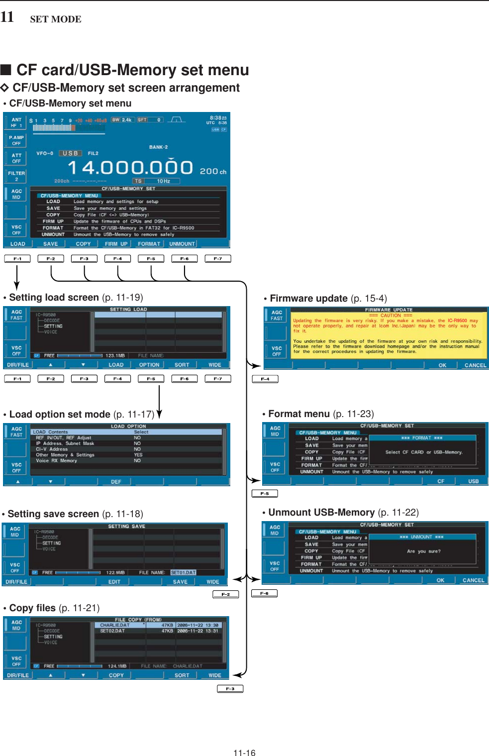
![11-1811 SET MODE■File savingMemory channel contents, set mode settings, etc. canbe saved into the CF (Compact Flash) memory card orUSB-memory for backup.qDuring set mode menu screen indication, push [F-7•CF/USB] to select CF/USB-Memory set menuscreen.wPush [F-2•SAVE] to select setting save screen.eChange the following conditions if desired.• File name:zPush [F-4•EDIT] to select file name edit con-dition.• Push [F-1• DIR/FILE] several times to select thefile name, if necessary.xPush [ABC], [123] or [Symbol] to select thecharacter group, then rotate the main dial toselect the character.• Push [123] or [Symbol] to toggle numerals andsymbols.• [ABC] : A to Z (capital letters); [123]: 0 to 9 (nu-merals); [Symbol]: ! # $ % & ‘ ` ^ + – = ( ) [ ] { } _ ~@ can be selected.• Push [F-1•Ω] to move the cursor left, push [F-2•≈]to move the cursor right, push [F-3•DEL] to deletea character and push [F-4•SPACE] to insert aspace.cPush [EXIT/SET] to set the file name.• Saving locationzPush [F-1•DIR/FILE] to select tree viewscreen.• Push and hold [F-1•DIR/FILE] for 1 sec. once ortwice to select the CF card or USB-Memory, whenUSB memory is Inserted.xSelect the desired directory or folder in the CFmemory card.• Push [F-4•Ω≈] to select the upper directory.• Push [F-2•Y] or [F-3•Z] to select folder in thesame directory.• Push and hold [F-4•Ω≈] for 1 sec. to select afolder in the directory.• Push [F-5•REN/DEL] to rename the folder.• Push and hold [F-5•REN/DEL] for 1 sec. to deletethe folder.• Push and hold [F-6•MAKE] for 1 sec. to making anew folder. (Edit the name with the same manneras the “• File name” above.)cPush [F-1•DIR/FILE] twice to select the filename.rPush [F-6•SAVE].• Confirmation screen appears.tPush [F-6•OK] to save.• After saving is completed, return to CF/USB-Memory setmenu automatically.[F-1•DIR/FILE][F-4•EDIT][F-6•SAVE]/[F-6•OK][F-7•WIDE]/[F-7•CANCEL][EXIT/SET] Main dial](https://usermanual.wiki/ICOM-orporated/284401.User-Manual-3/User-Guide-761726-Page-18.png)
![11-1911SET MODE■File loadingBy loading the saved setting file from the CF memorycard or USB-Memory, you can easily set up anotherIC-R9500—several operators settings can easily beapplied to one IC-R9500.qDuring set mode menu screen indication, push [F-7•CF/USB] to select CF/USB-Memory set menuscreen.wPush [F-1•LOAD] to select setting load screen.ePush [F-5•OPTION] to select load option set mode,then set the desired loading conditions, if desired.• See page 11-17 for details.rPush and hold [F-1•DIR/FILE] for 1 sec. once ortwice to select the CF card or USB-Memory, whenUSB memory is Inserted.tPush [F-2•Y] or [F-3•Z] to select the desired set-ting file.yPush [F-4•LOAD].• Confirmation screen appears.uPush [F-6•OK] to starts loading.• After the loading is completed, the message dialog, “Re-boot the IC-R9500,” appears.iTurn the receiver power OFF then ON to make thesetting effective.[F-1•DIR/FILE][F-5•OPTION][F-4•LOAD][F-6•SORT]/[F-6•OK][F-7•WIDE]/[F-7•CANCEL][F-3•Z][F-2•Y][EXIT/SET]](https://usermanual.wiki/ICOM-orporated/284401.User-Manual-3/User-Guide-761726-Page-19.png)
![11-2011 SET MODE■Changing the file nameThe file name, saved in the CF memory card or USB-memory, can be re-named from the receiver as de-sired.qDuring setting save screen display, push [F-1•DIR/FILE] to select tree view screen.• Push and hold [F-1•DIR/FILE] for 1 sec. once or twiceto select the CF card or USB-Memory, when USB mem-ory is Inserted.• Push [F-2•Y] or [F-3•Z] to select the desired folder.• “DECODE,” “SETTING” and “VOICE” folders are avail-able as the default.• After the folder is selected, push and hold [F-4•Ω≈] for1 sec. to display content folder(s), if available.wPush [F-1•DIR/FILE] to select file list screen.ePush [F-2•Y] or [F-3•Z] to select the desired file.rPush [F-5•REN/DEL] momentarily to select the filename edit condition.tPush [ABC], [123] or [Symbol] to select the charac-ter group, then rotate the main dial to select thecharacter.• Push [123] or [Symbol] to toggle numerals and symbols.• [ABC] : A to Z (capital letters); [123]: 0 to 9 (numerals);[Symbol]: ! # $ % & ‘ ` ^ + – = ( ) [ ] { } _ ~ @ can be se-lected.• Push [F-1•Ω] to move the cursor left, push [F-2•≈] tomove the cursor right, push [F-3•DEL] to delete a char-acter and push [F-4•SPACE] to insert a space.• Using the receiver’s keypad, [0]–[9], can also enter nu-merals.yPush [EXIT/SET] to set the file name.[F-1•DIR/FILE][F-5•REN/DEL][F-4•Ω≈][F-7•WIDE][F-3•Z][F-2•Y][EXIT/SET]](https://usermanual.wiki/ICOM-orporated/284401.User-Manual-3/User-Guide-761726-Page-20.png)
![11-2111SET MODE■File copyingMemory channel contents, set mode settings, etc. inCF card or USB-Memory can be copied betweenmemory devices for backup.qDuring set mode menu screen indication, push [F-7•CF/USB] to select CF/USB-Memory set menuscreen.wPush [F-3•COPY] to select file copy screen.• Select the original file(Example Copying CF card to USB-Memory)zPush [F-1•DIR/FILE] to select tree view screen.• Push and hold [F-1•DIR/FILE] for 1 sec. to select theCF card, if USB-Memory is selected.• Push [F-2•Y] or [F-3•Z] to select the desired folder.• After the folder is selected, push and hold [F-4•Ω≈]for 1 sec. to display content folder(s), if available.xPush [F-1•DIR/FILE] to select file list screen.cPush [F-2•Y] or [F-3•Z] to select the desired file.vPush [F-4•COPY] to select the file.• Saving location zPush and hold [F-1•DIR/FILE] for 1 sec. to selectthe USB-Memory.xSelect the desired directory or folder in the USB-Memory.• Push [F-4•Ω≈] to select the upper directory.• Push [F-2•Y] or [F-3•Z] to select folder in the samedirectory.• Push and hold [F-4•Ω≈] for 1 sec. to select a folderin the directory.• Push [F-5•REN/DEL] to rename the folder.• Push and hold [F-5•REN/DEL] for 1 sec. to delete thefolder.• Push [F-6•MAKE] for 1 sec. to making a new foldercPush [F-1•DIR/FILE] twice to select the filename.ePush [F-6•SAVE].• After saving is completed, return to CF/USB-Memory setmenu automatically.[F-1•DIR/FILE][F-4•EDIT][F-6•SAVE][F-7•WIDE][EXIT/SET] Main dial[F-4•COPY]](https://usermanual.wiki/ICOM-orporated/284401.User-Manual-3/User-Guide-761726-Page-21.png)
![11-2211 SET MODE■Deleting a file RECOMMENDATION! Deleting the setting file is ir-reversible. Confirm the contents before deleting asetting file!qDuring setting save screen display, push [F-1•DIR/FILE] to select tree view screen.• Push [F-2•Y] or [F-3•Z] to select the desired folder.• “DECODE,” “SETTING” and “VOICE” folders are avail-able as the default.• After the folder is selected, push and hold [F-2•Ω≈] for1 sec. to display content folder(s), if available.wPush [F-1•DIR/FILE] to select file list screen.ePush [F-2•Y] or [F-3•Z] to select the desired file tobe deleted.rPush and hold [F-5•REN/DEL] for 1 sec. • Confirmation screen appears.tPush [F-6•OK] to delete.• After the deleting, return to setting save screen auto-matically.■Unmount an USB-MemoryCAUTION! When removing the USB-Memory, un-mount operation is necessary. Unless otherwise in-side data of USB-Memory may be dameged.qPush and hold [F-6•UNMOUNT] for 1 sec.• Confirmation screen appears.wPush [F-6•OK] to unmount the USB-Memory.eAfter “ ” indication disappers, remove the USB-Memory.USB](https://usermanual.wiki/ICOM-orporated/284401.User-Manual-3/User-Guide-761726-Page-22.png)
![11-2311SET MODE■Formatting the CF card or USB-MemorySaved data in the CF card or USB-Memory can beerased.IMPORTANT! Formatting erases all saved data inthe CF card/USB-Memory. Backing up your memorydevice on your PC is recommended.qDuring CF/USB-Memory set menu display, pushand hold [F-4•FORMAT] for 1 sec.• Selection screen appears.wPush [F-6•CF] or [F-7•USB] to select CF card orUSB-Memory, respectively.ePush [F-6•FAT] or [F-7•FAT32] to select the formattype, FAT or FAT32, respectively.• Confirmation screen appears.rPush [F-6•OK] to format.• Push [F-7•CANCEL] to cancel.tReturns to CF card set menu indication automati-cally.NOTE: If no USB-Memory is inserted and [F-7•USB]is selected as in step w, an error message appears.](https://usermanual.wiki/ICOM-orporated/284401.User-Manual-3/User-Guide-761726-Page-23.png)
![11-2411 SET MODE■Display set (Video) modeThis set mode is used to set the HSB (Hue,Saturation, Brightness) color setting for video input oroutput, etc.NOTE: “Display set mode” is described on page 11-8.qPush [DISPLAY] momentarily to turn the mini TVscreen, if necessary.wPush and hold [DISPLAY] for 1 sec. to select thedisplay set (Video) mode.ePush [F-1•Y] or [F-2•Z] to select the desired setitem.rSet the desired condition using the main dial.• Push and hold [F-4•DEF] for 1 sec. to select a defaultcondition or value.tPush [EXIT/SET] to exit from set mode.NOTE: Video output from [DATA IN] is available anNTSC system only.[EXIT/SET][DISPLAY] Main dial[F-1•Y] [F-2•Z][F-4•DEF]Adjusts the saturation (vibrancy of the color) of thevideo signal from [VIDEO IN] jack. Adjustable rangeis 0 (shade of gray) to 100% (vivid color) in 1% steps.(default: 50%)Adjusts the hue (color type) of the video signal from[VIDEO IN] jack. Adjustable range is 0 (red) to 100(green) in 1 steps. (default: 50)NOTE: This setting is available when NTSC sys-tem signal is input from [VIDEO IN] connector.VIDEO IN Saturation50%VIDEO IN Hue (NTSC)50%Adjusts the LCD contrast of the video signal from[VIDEO IN] jack. Adjustable range is 0 (low contrast)to 100% (high contrast) in 1% steps. (default: 50%)VIDEO IN Contrast50%Adjusts the LCD brightness of the video signal from[VIDEO IN] jack. Adjustable range is 0 (dark) to 100%(bright) in 1% steps. (default: 50%)VIDEO IN Bright50%Selects the TV system of your local area from “NTSCM,” “PAL B/G,” “PAL I,” “PAL D” and “SECAM K.” NOTE: Default setting is different depending onversions.TV StandardNTSC M](https://usermanual.wiki/ICOM-orporated/284401.User-Manual-3/User-Guide-761726-Page-24.png)
![11-2511SET MODETrims the frame of the video signal from [VIDEO IN]jack. (default: ON) OFF : Displays the entire area of video signal.ON : Cuts the frame area (each 4% width of upper,bottom, left and right areas) and expands therest of area.Selects the wide screen capability ON and OFF. NOTE: This setting is effective for the full screenonly.VIDEO IN TrimmingONVIDEO IN Wide (Full)ON■Display set (Video) mode (continued)Selects the output video signal from pin 2 of [DATAIN] socket. (default: VIDEO IN) VIDEO IN : Outputs a video signal that is the same asthe input from [VIDEO IN] jack.LCD : Outputs a video signal that is the same asthe LCD.Adjusts the horizontal width of the output video signalfrom pin 2 of [DATA IN] socket. Adjustable range is 1(narrow) to 4 (wide) in 1 steps. (default: 1)VIDEO (DATA IN) OutputVIDEO INVIDEO Out Horizontal Size1Selects the setup level of the output video signal frompin 2 [DATA IN] socket. Selectable items are 0IRE(JPN NTSC) or 7.5IRE (USA NTSC).NOTE: Default setting is different depending onversions.Adjusts the saturation (vibrancy of the color) of theoutput video signal from pin 2 of [DATA IN] jack. Ad-justable range is 0 (shade of gray) to 100% (vividcolor) in 1% steps. (default: 80%)VIDEO Out Setup Level7.5IREVIDEO Out Saturation80%Adjusts the hue (color type) of the output video signalfrom pin 2 of [DATA IN] jack. Adjustable range is 0(red) to 100 (green) in 1 steps. (default: 50)VIDEO Out Hue50%](https://usermanual.wiki/ICOM-orporated/284401.User-Manual-3/User-Guide-761726-Page-25.png)
![11-2611 SET MODE■LCD set modeThis set mode is used to set the LCD contrast, bright-ness and other settings for 2 condition of the dimmerfunction ON and OFF.qPush [LCD SET] to select LCD set mode.wPush [DIMMER] once or twice to select the dimmerfunction ON or OFF.ePush [F-1•Y] or [F-2•Z] to select the desired setitem.rSet the desired condition using the main dial.• Push and hold [F-4•DEF] for 1 sec. to select a defaultcondition or value.• Push and hold [DIMMER] for 1 sec. to reset to a defaultcondition or value for all items at the same time.tPush [DIMMER] once to select the other dimmersetting, and repeat steps eand r.• Dimmer function OFF yPush [EXIT/SET] to exit from set mode.• Dimmer function ON[EXIT/SET][DIMMER] [LCD SET] Main dial[F-1•Y] [F-2•Z][F-4•DEF]Adjusts the brightness of LCD unit from 0 (dark) to100% (bright) range in 1% steps. Default setting:Dimmer function OFF : 50%Dimmer function ON : 50%Adjusts the brightness of switch indicators from 1(dark) to 100 (bright) range in 1 steps. Default setting:Dimmer function OFF : 50%Dimmer function ON : 25%LCD Unit Bright50%Backlight (Switches)50%Adjusts the contrast of the LCD from 0 (low contrast)to 100% (high contrast) range in 1% steps. Default setting:Dimmer function OFF : 75%Dimmer function ON : 25%Contrast (LCD)75%Adjusts the brightness of the LCD from 0 (dark) to100% (bright) range in 1% steps. Default setting:Dimmer function OFF : 100%Dimmer function ON : 25%Bright (LCD)100%](https://usermanual.wiki/ICOM-orporated/284401.User-Manual-3/User-Guide-761726-Page-26.png)
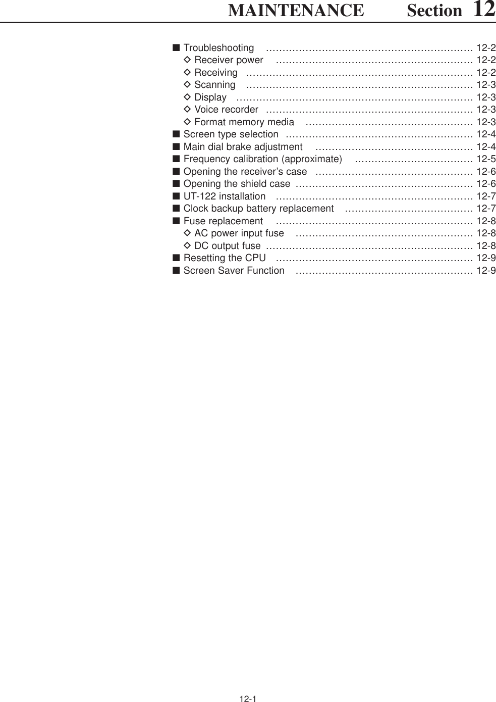
![■TroubleshootingThe following chart is designed to help you correctproblems which are not equipment malfunctions.If you are unable to locate the cause of a problem orsolve it through the use of this chart, contact you near-est Icom Dealer or Service Center.DReceiver powerDReceivingPROBLEM POSSIBLE CAUSE SOLUTION REF.No sounds come out fromthe speaker.Sensitivity is too low, andonly strong signals areaudible.Received audio is unclearor distorted.The [ANT] switch does notfunction[AFC] cannot be turnedON.[AUTOTUNE](AFC) can-not be turned ON.[VSC] cannot be turnedON.[ANF] cannot be turnedON.[NOTCH1]/[NOTCH2]cannot be turned ON.The filter width cannot bechanged.A synthesized voice is notemitted when pushing[SPCH].• Volume level is too low.• The squelch is closed.• The RF gain is too decreases sensitivity.• The antenna is not connected properly.• The attenuator is activated.• A different antenna for HF band is selected.• Wrong operating mode is selected.• PBT function is activated.• Noise blanker is turned ON when receiving astrong signal.• Preamp is activated.• The noise reduction is activated and the [NR]control is too far clockwise.• The selected frequency is above 30 MHz.• The operating mode is not set in FM or WFMmode.• The operating mode is set in FM, WFM, FSKor P25 mode.• The operating mode is set in CW, FSK or P25mode.• The operating mode is not set in FM or WFMmode.• The operating mode is set in FM, WFM or P25mode.• The operating mode is set in WFM or P25mode.• “SPEECH Mix” in the others set mode is OFF.• Rotate [AF] clockwise to obtain a suitable lis-tening level.• Turn [SQL] to 10 o’clock position to open thesquelch.• Rotate [RF GAIN] clockwise to obtain anenough sensitivity.• Re-connect the antenna.• Push [ATT] several times to select “ATT OFF.”• Push [ANT] several times to select the correctantenna for the HF band.• Select a suitable operating mode.• Push [PBT CLR] for 1 sec. to reset the function.• Push [NB] to turn the noise blanker OFF.• Push [P.AMP] once or twice to turn the functionOFF.• Set the [NR] control for maximum readability.• Select a frequency below 30 MHz.• Select FM or WFM mode to activate AFC.• Select AM, SSB or CW mode to activate AUTO-TUNE.• Select FM, WFM, AM or SSB mode to activateVSC.• Select FM or WFM mode to activate ANF.• Select AM, SSB, CW and FSK mode to activateMN1/MN2.• Select FM, AM, SSB, CW and FSK mode.• Set “SPEECH Mix” to All or Operation in the setmode.p. 3-8p. 3-8p. 3-8—p. 5-9p. 9-3p. 3-7p. 5-11p. 5-15p. 5-9p. 5-16pgs. 3-4, 9-3pgs. 3-7, 5-17pgs. 3-7, 5-17pgs. 3-7, 8-3pgs. 3-7, 5-16pgs. 3-7, 5-16pgs. 3-7, 5-12p. 11-11PROBLEM POSSIBLE CAUSE SOLUTION REF.12-212 MAINTENANCEPower does not come onwhen the [POWER] switchis pushed.• Power cable is improperly connected.• The internal power supply is turned OFF.• The fuse is blown.• Re-connect the AC power cable correctly.• Turn the internal power supply ON.• Check for the cause, then replace the fuse.—p. 3-2p.12-8](https://usermanual.wiki/ICOM-orporated/284401.User-Manual-3/User-Guide-761726-Page-28.png)
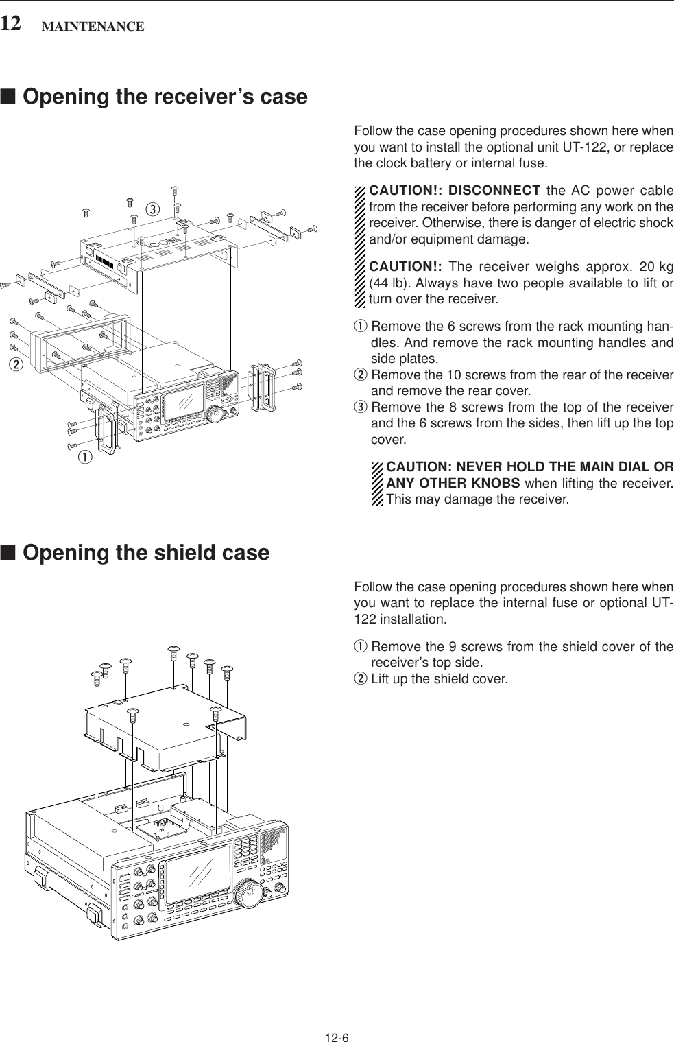
![DScanningDDisplayDVoice recorderDFormat memory media12-312MAINTENANCEPROBLEM POSSIBLE CAUSE SOLUTION REF.Programmed scan doesnot stop.Scan does not start.(Programmed scan)(Memory scan)(Select memory scan)(Mode select memory scan)(∂F scan)(Auto memory write scan)• Squelch is open.•The same frequencies have been programmedin scan edge memory channels PxA and PxB.• 2 or more memory channels have not beenprogrammed.• 2 or more memory channels have not beendesignated as select channels.• 2 or more memory channels with desiredmode have not been programmed.• The center frequency for ∂F scan does notprogrammed.• Auto write bank is full.• Readjust the [SQL] threshold.• Program different frequencies in scan edgememory channel PxA and PxB.• Program more than 2 memory channels.• Designate more than 2 memory channels asselect channels for the scan.• Program more than 2 memory channels withdesired operating mode.• Program the center frequency for ∂F scan.• Clear the memory channels of auto write bank.pgs. 3-8, 8-3p. 8-6pgs. 7-4, 8-11p. 8-12pgs. 7-4, 8-14p. 8-8pgs. 7-7, 8-4PROBLEM POSSIBLE CAUSE SOLUTION REF.The displayed frequencydoes not change properly.The key operation on thefront panel does not func-tion.• The dial lock function is activated.• The panel lock function is activated.•Push [LOCK] to turn the function OFF.• Push [PANEL LOCK] to turn the function OFF.p. 9-2p. 9-2PROBLEM POSSIBLE CAUSE SOLUTION REF.The voice recorder cannotrecord.The voice recorder stopsrecording.• The selected memory media is full.• The recording memory media is full.• The recording file size is at maximum (2 GB).•Select a different memory media or clear theunnecessary files.•Select a different memory media or clear theunnecessary files.• Select a lower sound quality for long durationrecording.p. 6-4p. 6-4p. 6-6PROBLEM POSSIBLE CAUSE SOLUTION REF.Format error appearswhen formatting in FAT32Format error appearswhen formatting in FAT• The inserted memory media capacity is small-er than 64 MB.• The inserted memory media capacity is largerthan 2 GB.•Insert a memory media larger than 64 MB orselect the FAT format.•Insert a memory media smaller than 2 GB orselect the FAT32 format.p. 11-23p. 11-23](https://usermanual.wiki/ICOM-orporated/284401.User-Manual-3/User-Guide-761726-Page-29.png)
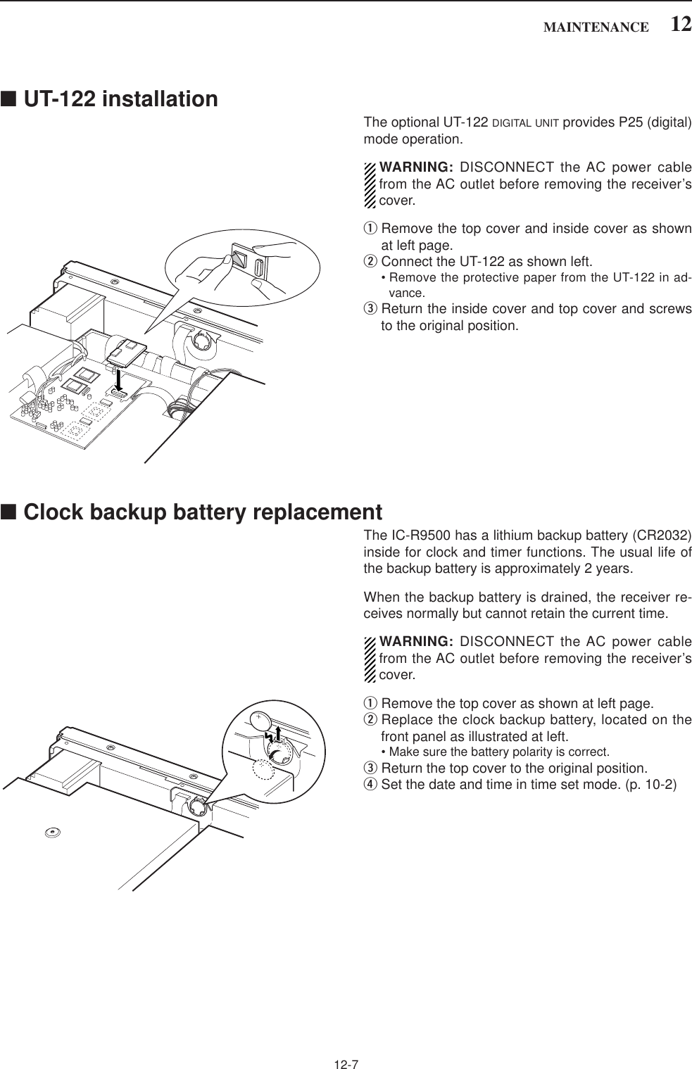
![12-4■Screen type selection2 types of screen images are available in the IC-R9500.qPush [EXIT/SET] several times to close multifunc-tion screen, if necessary.wPush [F-7•SET] to select set mode menu screen.ePush [F-3•DISP] to enter the display set mode.rPush [F-1•Y] or [F-2•Z] to select “Display Type”item.tRotate the main dial to select the desired screenimage.• Screen image is selectable from A and B.yPush [EXIT/SET] twice to exit from the display setmode.(Blue display)• Screen image example— type B(Black display)■Main dial brake adjustmentThe tension of the main dial may be adjusted to suityour preference.The brake adjustment is located on the bottom side ofthe front panel. See the figure at left.Slide the brake adjustment to a comfortable tensionlevel while turning the dial continuously and evenly inone direction.LightHeavy[MAIN DIAL]Brakeadjustment12 MAINTENANCE• Screen image example— type A (default)](https://usermanual.wiki/ICOM-orporated/284401.User-Manual-3/User-Guide-761726-Page-30.png)
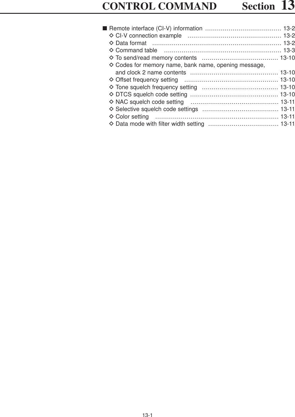
![12-5■Frequency calibration (approximate)A very accurate frequency counter is required to cali-brate the frequency of the receiver. However, a roughcheck may be performed by receiving radio stationWWV, WWVH, or other standard frequency signals.CAUTION: The IC-R9500 has been thoroughly ad-justed and tested at the factory before beingshipped. You should not have to re-calibrate it.qPush [SSB] to select USB mode.wPush and hold [PBT CLEAR] for 1 sec. to clear thePBT setting.eSet the frequency to the standard frequency stationminus 1 kHz.• When receiving WWV or WWVH (at 15.00000 MHz) asa standard frequency, set the operating frequency for14.99900 MHz.• Other standard frequencies can be used.rPush [EXIT/SET] several times to close a multi-function screen, if necessary.tPush [F-7•SET] to select set mode menu screen.• Calibration marker item yPush [F-5•OTHERS] to enter the others set mode.uPush [F-1•Y] several times to select the “Calibra-tion Marker” item.iRotate the main dial clockwise to turn the calibra-tion marker ON.oPush [EXIT/SET] once to return to set mode menuscreen.!0 Push [F-2•ACC] to enter accessory set mode.!1 Push [F-2•Z] several times to select the “REF Ad-just” item.!2 Rotate the main dial to adjust for a zero beat withthe received standard signal as shown at left.• Zero beat means that two signals are exactly the samefrequency, resulting in a single tone being emitted.• REF Adjust item !3 Turn the calibration marker OFF in the others setmode.!4 Push [EXIT/SET] twice to exit set mode.[F-1•Y][F-2•ACC]/[F-2•Z]Main dial[EXIT/SET][F-4•DEF] [F-7•SET][F-5•OTHERS]12MAINTENANCE](https://usermanual.wiki/ICOM-orporated/284401.User-Manual-3/User-Guide-761726-Page-31.png)
![12-812 MAINTENANCE■Fuse replacementIC-R9500 has two fuses for receiver protection.AC power input : 4 A (for 100/120 V AC versions)2 A (for 230/240 V AC versions)DC output jack : 1 AIf the fuse blows or the receiver stops functioning, findthe sources of the problem, if possible, and replace thedamaged fuse with a new fuse of the same rating.WARNING: DISCONNECT the AC power cablefrom the AC outlet before removing the receiver’scover. This can prevent shock to the user or dam-age to the receiver. DAC power input fuse The AC power input fuse is held in the [FUSE] holder.qUnscrew the [FUSE] holder using a standard screwdriver.wReplace the open fuse with a new, properly ratedone as shown at left.DDC output fuse When no external DC output is available from [EXTDC] and ACC connector, the internal fuse may beopen. Replace the fuse in this case.qRemove the top cover and shield case as shown atpage 12-6.wReplace the open fuse with a new, properly ratedone (FGB 1 A) as shown at left.eReplace the shield case and top cover.](https://usermanual.wiki/ICOM-orporated/284401.User-Manual-3/User-Guide-761726-Page-34.png)
![12-912MAINTENANCE■Resetting the CPUqTurn the main power switch on the rear panel ON.• Make sure the receiver power is still OFF.wWhile pushing and holding [CE] and [M-CL], push[POWER] to turn power ON.• The internal CPU is reset.• The CPU start-up takes approx. 5 sec.• The receiver displays its initial VFO frequencies whenresetting is complete.eCorrect the set mode settings after resetting, if de-sired.NOTE: Resetting CLEARS all programmed con-tents in memory channels and returns programmedvalues in set mode to default values.■Screen saver functionThe IC-R9500 has a screen saver function to protectthe LCD from the “burn-in” effect.qPush [EXIT/SET] several times to close a multi-function screen, if necessary.wPush [F-7•SET] to select set mode menu screen.ePush [F-3•DISP] to enter the display set mode.rPush [F-1•Y]/[F-2•Z] several times to select the“Screen Saver Function” item.tRotate main dial to select the desired time periodfor the screen saver activation from 15, 30, 60 min.and OFF.• Deactivate the screen saver with “OFF” selection.yPush [EXIT/SET] twice to exit the set mode.[F-1•Y] [F-2•Z]Main dial[EXIT/SET][F-4•DEF] [F-7•SET]/[F-7•WIDE][F-3•DISP][F-5•PREVIEW][CE] [M-CL][POWER]ALL CLEARiR9500](https://usermanual.wiki/ICOM-orporated/284401.User-Manual-3/User-Guide-761726-Page-35.png)
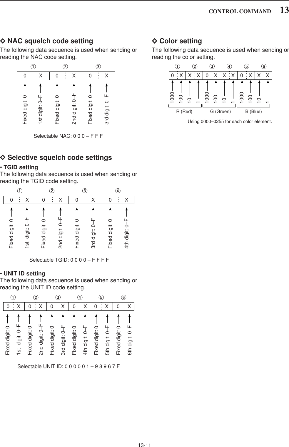
![13-3DCommand table13CONTROL COMMAND00 — Send frequency data01 Same as Send mode datacommand 0602 — Read upper/lower frequencies forselected band03 — Read operating frequency04 — Read operating mode05 — Set operating frequency 06 00 Select LSB01 Select USB02 Select AM03 Select CW04 Select FSK05 Select FM07 Select CW-R08 Select FSK-R11 Select S-AM(D)14 Select S-AM(L)15 Select S-AM(U)16 Select P2507 — Select (Last selected) VFO mode08 — Select memory mode0–1219* Select memory channel*0–999, 1000–1099 (A00–A99),1100–1199 (S00–S99),1200–1219 (P0A–P9A)0–12* Select memory bank*0–9, 10 (Bank-A), 11 (Bank-S),12 (Bank-P)09 — Memory write0A — Memory to VFO0B — Memory clear0C — Read offset frequency (see p. 13-10 for details)0D — Set offset frequency (see p. 13-10 for details)0E 00 Scan stop01 Programmed scan (Prog 0)/memory scan start02 Programmed scan (Prog 0) start03 ∂F scan start04 Auto memory write scan start12 Fine programmed scan start13 Fine ∂F scan start22 Memory scan start23 Select memory scan start24 Mode select memory scan start42 Priority scan (Prio 0) startA0 Set ∂F scan Fixed frequency ON AA Set ∂F scan Fixed frequency OFFA1–A7 Set ∂F scan span (A1=±5 kHz;A2=±10 kHz; A3=±20 kHz;A4=±50 kHz; A5=±100 kHz; A6=±500 kHz; A7=±1 MHz)B0 Set as non-select channelB1 Set as select channel (1–9=★(SEL)1–9; when no datacommand is specified, the previous-ly set number or “★1” is selected)B2 Set the number for select memoryscan (0=ALL; 1–9=★(SEL)1–9D0 Set scan resume OFF0E D1 Set scan resume ON(Close Timer)D3 Set scan resume ON(Close and Delay)10 Turn duplex OFF. (Simplex)11 Turn duplex ON. (DUP–)12 Turn duplex ON. (DUP+)10 00 Select 1 Hz tuning step01 Select 10 Hz tuning step02 Select 100 Hz tuning step03 Select 1 kHz tuning step04 Select 2.5 kHz tuning step05 Select 5 kHz tuning step06 Select 6.25 kHz tuning step07 Select 9 kHz tuning step08 Select 10 kHz tuning step09 Select 12.5 kHz tuning step10 Select 20 kHz tuning step11 Select 25 kHz tuning step12 Select 100 kHz tuning step13 Select 1 MHz tuning step14 Select Prog tuning step11 — Select/read attenuator (00=OFF;06=6 dB; 10=10 dB; 12=12 dB;18=18 dB; 20=20 dB; 24=24 dB;30=30 dB)12 00 Select/read the antenna below 01 30 MHz. (00=HF ANT1,02 01=HF ANT2, 02=HF ANT3) 13 00 Announce with voice synthesizer01 (00=all data; 01=frequency and 02 S-meter level; 02=receive mode)14 01 + Level data [AF] level setting (0=max. CCW to 255=max. CW)02 + Level data [RF] level setting (0=max. CCW to 255=11 o’clock)03 + Level data [SQL] level setting (0=11 o’clock to 255=max. CW)06 + Level data [NR] level setting (0=min. to 255=max.)07 + Level data Left [TWIN PBT] setting or IF shiftsetting (0=max. CCW, 128=center,255=max. CW)08 + Level data Right [TWIN PBT] setting (0=max. CCW, 128=center,255=max. CW)09 + Level data [CW PITCH] setting (0=300 Hz, 128=600 Hz,255=900 Hz; 5 Hz steps)0D + Level data [NOTCH1] setting (0=low freq. to 255=high freq.)11 + Level data [AGC] control setting (0=max.CCW to 255=max. CW)12 + Level data [NB] control setting (0=max. CCW to 255=max. CW)18 + Level data [CONTRAST] setting (0=max.CCW to 255=max. CW)19 + Level data [BRIGHT] setting (0=max. CCW to 255=max. CW)1A + Level data [NOTCH2] setting (0=low freq. to 255=high freq.)1B + Level data [BASS] setting (0=max. CCW to 255=max. CW)1C + Level data [TREBLE] setting (0=max. CCW to 255=max. CW)Command Sub command Description Command Sub command Description](https://usermanual.wiki/ICOM-orporated/284401.User-Manual-3/User-Guide-761726-Page-39.png)
![13-4DCommand table (continued)13 CONTROL COMMAND14 1D + Level data [SCAN SPEED] setting (0=max. CCW to 255=max. CW)1E + Level data [SCAN DELAY] setting (0=max. CCW to 255=max. CW)15 01 Read squelch status02 Read signal (S-meter) level03+Sign+M-type Read signal (dB meter) levelSign: 0/1=+/–, M-type 0/1/2=dBµ,dBµ[EMF], dBm04 Read center meter level16 02 Preamp (0=OFF; 1=preamp 1;2=preamp 2)12 AGC selection (0=OFF; 1=Fast;2=Mid; 3=Slow)22 Noise blanker (0=OFF, 1=NB1, 2=NB2)32 Audio peak filter (APF type isSHARP; 0=OFF, 1=320 Hz,2=160 Hz, 3=80 Hz), (APF type isSOFT; 0=OFF, 1=WIDE, 2=MID,3=NAR)40 Noise reduction (0=OFF; 1=ON)41 Auto notch (0=OFF; 1=ON)43 Tone squelch (0=OFF; 1=ON)48 Manual notch1 (0=OFF; 1=ON)4A AFC (0=OFF; 1=ON)4B DTCS squelch (0=OFF; 1=ON)4C VSC (0=OFF; 1=ON)4D Manual AGC (0=OFF; 1=ON)4F Twin peak filter (0=OFF; 1=ON)50 Dial lock (0=OFF; 1=ON)51 Manual notch2 (0=OFF; 1=ON)52 P25 Digital squelch (0=OFF; 1=NAC, 2=SEL)19 00 Read the receiver information1A 00 Send/read memory contents (seep. 13-10 for details)03 Send/read the selected filter width(AM: 0=200 Hz to 49=10 kHz;SSB, CW: 0=50 Hz to 40=3600 Hz;FSK: 0=50 Hz to 31=2700 Hz)04 Send/read the selected AGC timeconstant (AM: 0=OFF, 1=0.3 sec.to 13=8.0 sec., SSB, CW, FSK:0=OFF, 1=0.1 sec. to 13=6.0 sec.)050001 Send/read FM Tone (Bass) level(0=–15 to 30=+15)050002 Send/read FM Tone (Treble) level(0=–15 to 30=+15)050003 Send/read WFM Tone (Bass)level (0=–15 to 30=+15)050004 Send/read WFM Tone (Treble)level (0=–15 to 30=+15)050005 Send/read AM Tone (Bass) level(0=–15 to 30=+15)050006 Send/read AM Tone (Treble) level(0=–15 to 30=+15)050007 Send/read SSB Tone (Bass) level(0=–15 to 30=+15)050008 Send/read SSB Tone (Treble)level (0=–15 to 30=+15)050009 Send/read CW Tone (Bass) level(0=–15 to 30=+15)050010 Send/read CW Tone (Treble) level(0=–15 to 30=+15)1A 050011 Send/read FSK Tone (Bass) level(0=–15 to 30=+15)050012 Send/read FSK Tone (Treble)level (0=–15 to 30=+15)050013 Send/read De-emphasis (FM 50k)(0=OFF, 1=ON)050014 Send/read De-emphasis (FM 15k)(0=OFF, 1=ON)050015 Send/read De-emphasis (FM 7k)(0=OFF, 1=ON)050016 Send/read AF high-cut filter (FM50k) (0=OFF, 1=ON)050017 Send/read AF high-cut filter (FM15k) (0=OFF, 1=ON)050018 Send/read AF high-cut filter (FM7k) (0=OFF, 1=ON)050019 Send/read AF high-cut filter(WFM) (0=OFF, 1=ON)050020 Send/read AF high-cut filter (AM)(0=OFF, 1=ON)050021 Send/read AF high-cut filter (SSB)(0=OFF, 1=ON)050022 Send/read AF high-cut filter (CW)(0=OFF, 1=ON)050023 Send/read AF high-cut filter (FSK)(0=OFF, 1=ON)050024 Send/read AF high-cut filter (P25)(0=OFF, 1=ON)050025 Send/read speech level (0=0% to 255=100%)050026 Send/read beep gain (0=0% to 255=100%)050027 Send/read beep gain limit (0=OFF, 1=ON)050028 Send/read headphones outputratio (0=0.60 to 255=1.40)050029 Send/read SPEECH OUTPUTlevel (0=0% to 255=100%)050030 Send/read S/P DIF output level(0=0% to 255=100%)050031 Send/read REC REMOTE output(0=OFF, 1=ON)050032 Send/read external meter outputselection(0=Signal, 1=Signal+SQL)050033 Send/read external meter outputlevel(0=0% to 255=100%)050034 Send/read reference signal in/outsetting (0=IN, 1=OFF, 2=OUT)050035 Send/read reference signal fre-quency setting (0=0% to 255=100%)050036 Send/read screen image type(0=A, 1=B)050037 Send/read signal meter type (0=S,1=dBµ, 2=dBµ[EMF], 3=dBm050038 Send/read meter peak hold set (0=OFF, 1=ON)050039 Send/read memory name indica-tion setting (0=OFF, 1=ON)050040 Send/read audio peak filter widthpop-up indication setting (0=OFF, 1=ON)050041 Send/read manual notch widthpop-up indication setting(0=OFF, 1=ON)Command Sub command Description Command Sub command Description](https://usermanual.wiki/ICOM-orporated/284401.User-Manual-3/User-Guide-761726-Page-40.png)
050082 Send/read the LCD brightness ofthe video signal from [VIDEO IN](0=0% to 255=100%)050083 Send/read the saturation of thevideo signal from [VIDEO IN](0=0% to 255=100%)050084 Send/read the hue of the videosignal from [VIDEO IN] (0=0% to 255=100%)050085 Send/read the frame trimming ofthe video signal from [VIDEO IN].(0=OFF, 1=ON)050086 Send/read the wide screen set.(0=OFF, 1=ON)050087 Send/read the output video signalfrom [DATA IN](0=VIDEO IN, 1=LCD)050088 Send/read the width of the outputvideo signal from [DATA IN](0=1 (narrow) to 3=4 (wide))050089 Send/read setup of the outputvideo signal from [DATA IN](0=0IRE (JPN NTSC), 1=7.5IRE(USA NTSC))050090 Send/read output saturation levelfrom [DATA IN](0=0% to 255=100%)050091 Send/read output hue level from[DATA IN]. (0=0% to 255=100%)050092 Send/read the LCD contrast withdimmer OFF condition(0=0% to 255=100%)050093 Send/read the LCD brightnesswith dimmer OFF condition(0=0% to 255=100%)Command Sub command Description Command Sub command Description](https://usermanual.wiki/ICOM-orporated/284401.User-Manual-3/User-Guide-761726-Page-41.png)
![13-6DCommand table (continued)13 CONTROL COMMAND1A 050094 Send/read the LCD unit brightnesswith dimmer OFF condition(0=0% to 255=100%)050095 Send/read the key backlight withdimmer OFF condition(0=0% to 255=100%)050096 Send/read the LCD contrast withdimmer ON condition(0=0% to 255=100%)050097 Send/read the LCD brightnesswith dimmer ON condition(0=0% to 255=100%)050098 Send/read the LCD unit brightnesswith dimmer ON condition(0=0% to 255=100%)050099 Send/read the key backlight withdimmer ON condition(0=0% to 255=100%)050100 Send/read scope max. hold(0=OFF, 1=ON)050101 Send/read scope center frequen-cy set (0=Filter center, 1=Carrierpoint center, 2=Carrier point cen-ter (Abs. Freq.))050102 Send/read waveform color forreceiving signal (see p. 13-11 for details)050103 Send/read waveform color formax. hold(see p. 13-11 for details)050104 Send/read marker color for receiv-ing signal(see p. 13-11 for details)050105 Send/read marker color for max.hold (see p. 13-11 for details)050106 Send/read scope peak excursion(0=0 dB to 80=80 dB)050107 Send/read scope peak threshold(0=–100 dB to 100=0 dB)050108 Send/read voice recorder’s shortplay time (3=3 sec. to 10=10 sec.)050109 Send/read voice recorder shortrecord time (5=5 sec. to 30=30 sec.)050110 Send/read voice recorder’srecording quality(0=SQ1 (8 kHz), 1=SQ2 (12 kHz),2=HQ1 (16 kHz) 3=HQ2(24 kHz)4=SHQ (48 kHz))050111 Send/read REC remote set(0=OFF, 1=ON)050112 Send/read SPEECH Mix set(0=OFF, 1=Operation, 2=All)050113 Send/read speech mix level(0=0% (Receive audio only) to255=100% (Speech audio only))050114 Send/read memory bank limit setfor memory channel selection(0=OFF, 1=ON)050115 Send/read memory bank limit setfor memory scan (0=OFF, 1=ON)050116 Send/read memory bank name(Bank-0) (see p. 13-10 for details)050117 Send/read memory bank name(Bank-1) (see p. 13-10 for details)1A 050118 Send/read memory bank name(Bank-2) (see p. 13-10 for details)050119 Send/read memory bank name(Bank-3) (see p. 13-10 for details)050120 Send/read memory bank name(Bank-4) (see p. 13-10 for details)050121 Send/read memory bank name(Bank-5) (see p. 13-10 for details)050122 Send/read memory bank name(Bank-6) (see p. 13-10 for details)050123 Send/read memory bank name(Bank-7) (see p. 13-10 for details)050124 Send/read memory bank name(Bank-8) (see p. 13-10 for details)050125 Send/read memory bank name(Bank-9) (see p. 13-10 for details)050126 Send/read memory bank name(Bank-A) (see p. 13-10 for details)050127 Send/read memory bank name(Bank-S) (see p. 13-10 for details)050128 Set/read FFT scope averaging setfor FSK decoder (0=OFF, 1=2, 2=3, 3=4)050129 Set/read FFT scope waveformcolor set for FSK decoder (see p. 13-11 for details)050130 Send/read FSK decode USOS(0=OFF, 1=ON)050131 Send/read FSK decode new linecode(0=CR,LF,CR+LF, 1=CR+LF)050132 Send/read clock selection for timestamp (0=Local time, 1=Clock 2)050133 Send/read frequency stamp(0=OFF, 1=ON)050134 Send/read FSK received text fontcolor (see p. 13-11 for details)050135 Send/read time stamp text fontcolor (see p. 13-11 for details)050136 Send/read skip scan set(0=OFF, 1=ON)050137 Send/read auto memory scanmemory clear set (0=OFF,1=[AUTO] Long Push, 2=ON)050138 Send/read auto scan screen setwhen scan start (0=OFF, 1=ON)050139 Send/read NB1 depth (0=1 to 9=10)050140 Send/read NB1 width (0=0 to 255=100)050141 Send/read NB2 depth (0=1 to 9=10)050142 Send/read NB2 width (0=0 to 255=100)050143 Send/read TS (1 Hz) as selectabletuning step for FM(0=OFF, 1=ON)050144 Send/read TS (10 Hz) as selec-table tuning step for FM(0=OFF, 1=ON)050145 Send/read TS (100 Hz) as selec-table tuning step for FM(0=OFF, 1=ON)050146 Send/read TS (1 kHz) as selec-table tuning step for FM(0=OFF, 1=ON)Command Sub command Description Command Sub command Description](https://usermanual.wiki/ICOM-orporated/284401.User-Manual-3/User-Guide-761726-Page-42.png)
![13-1013 CONTROL COMMANDDTo send/read memory contentsWhen sending or reading memory contents, additionalcodes must be added to appoint the memory channelas follows.➥Additional code: 0000–1219• Memory channel code • Memory bank code DCodes for memory name, bank name,opening message and clock 2 namecontentsTo send or read the desired memory name settings,the character codes as follows are used. •Character’s code•Character’s code— Symbols DOffset frequency settingThe following data sequence is used when sending orreading the offset frequency setting.DTone squelch frequency settingThe following data sequence is used when sending orreading the tone frequency setting.DDTCS squelch code settingThe following data sequence is used when sending orreading the DTCS code setting.DTCS Polarity†, ‡: 0. 1100 digit: 0–710 digit: 0–71 digit: 0–7Fixed digit: 0†Fixed digit: 0q†00X X XweX†Not necessary when normal is set.‡0=Normal, 1=Reverse100Hz digit: 0–210 Hz digit: 0–91 Hz digit: 0–90.1 Hz digit: 0–9Fixed digit: 0*Fixed digit: 0*q*00XXXweX*Not necessary when setting a frequency.1 kHz digit: 0–9100 Hz digit: 0 (fixed)100 kHz digit: 0–910 kHz digit: 0–910 MHz digit: 0–91 MHz digit: 0–4q0XXXXXXwe r01 GHz digit: 0 (fixed)100 MHz digit: 0–4Character ASCII code Description0–9 30–39 NumeralsA–Z 41–5A Alphabetical charactersa–z 61–7A Alphabetical charactersspace 20 Word spaceCharacter ASCII code Character ASCII code!21#23$24%25&26¥5C?3F” 22’27`60^5E+2B–2D✱2A/2F.2E,2C:3A;3B=3D<3C>3E(28)29[5B]5D{7B}7D|7C_5F–7E @ 40Code Bank number Memory Cnannel0000–0999 Bank-0–Bank-9 0–9991000–1099 Bank-A (Auto) A00–A991100–1199 Bank-S (Skip) S00–S991200–1219 Bank-P (Scan edge) P0A–P9BCode Bank number00–09 Bank-0–Bank-910 Bank-A (Auto)11 Bank-S (Slip)12 Bank-P (Scan edge)](https://usermanual.wiki/ICOM-orporated/284401.User-Manual-3/User-Guide-761726-Page-46.png)
![14-2■SpecificationsDGeneral• Frequency coverage (unit: MHz) :USA 0.005000–821.999999, 851.000000–866.999999896.000000–3335.000000France 0.050000–29.999999, 50.200000–51.200000,87.500000–108.000000, 144.000000–146.000000,430.000000–440.000000, 1240.000000–1300.000000Europe, U.K., Canada, EXP, Australia 0.005000–3335.000000• Operating mode : USB, LSB, CW, FSK, AM, FM, WFM, P25• Number of memory channels : 1220 (1000 regular channels, 100 auto memory writechannels, 100 skip channels, 20 scan edge channels)• Antenna connector : Type-N×2 (antenna impedance: 50 ),SO-239×1 (antenna impedance: 50 ),Phono (RCA)×1 (antenna impedance: 500 )• Operating temperature range : 0˚C to +50˚C; +32˚F to +122˚F• Frequency stability : Less than ±0.05 ppm (approx. 5 min. after from turn themain power, [I/O], ON, 0–50˚C; 32–122˚F)• Frequency resolution : 1Hz• Power supply requirement : 100 V, 120 V, 230 V, 240 V AC• Power consumption :Receive Stand-by Less than 100 VAMax. audio Less than 100 VA• Dimensions (projections not included) :424×149×340 mm; 1611⁄16×57⁄8×133⁄8in• Weight : Approx. 20 kg; 44 lb• ACC connector : 8-pin DIN connector• DATA IN connector : 8-pin DIN connector• Display*:7-inch (diagonal) TFT color LCD (800×480)• EXT-DISPLAY connector : D-sub 15S • RS-232C connector : D-sub 9-pin• VIDEO IN connector : Phono (RCA)• VIDEO OUT connector : Phono (RCA)• SPEECH OUT connector : Phono (RCA)• LINE OUT connector : Phono (RCA)• USB connector : USB (Universal Serial Bus)1.1/2.0• CI-V connector : 2-conductor 3.5 (d) mm (1⁄8w)• ANT-SEL connector : 3-conductor 3.5 (d) mm (1⁄8w)• DET OUT connector : 3-conductor 3.5 (d) mm (1⁄8w)• EXT-SP connectors : 2-conductor 3.5 (d) mm (1⁄8w)/8 • REC REMOTE connector : 3-conductor 3.5 (d) mm (1⁄8w)×2(Front and rear panels)• REC OUT connector : 3-conductor 3.5 (d) mm (1⁄8w)• PHONES connector : 3-conductor 3.5 (d) mm (1⁄8w)14 SPECIFICATIONS AND OPTIONSAll stated specifications are typical and subject to change without notice or obligation.](https://usermanual.wiki/ICOM-orporated/284401.User-Manual-3/User-Guide-761726-Page-50.png)
![15-3■PreparationDFirmware and firm utility The latest firmware and the firm utility can be down-loaded from the Icom home page via the INTERNET.Access the following URL to download the firm utilityand the latest firmware.http://www.icom.co.jp/world/download/index.htmFor updating from the USB-MemoryWhen updating the firmware from the USB-Memory,copy the downloaded firmware data (e.g. 9500xxxx.dat)to the USB-Memory (in “IC-R9500” folder) using an avail-able USB port (USB hub may be required; purchased sep-arately from your PC dealer).DFile downloadingqAccess the following URL directly.http://www.icom.co.jp/world/download/index.htm• No link is available from the top page.wRead “Regarding this Download Service” carefully,then click [AGREE].eClick “IC-R9500” link then click the firmware file link.rClick [Save] in the displayed File Download dialog.tSelect the desired location to whichyou want tosave the firmware, then click [Save] in the displayedFile Download dialog.• File download starts.yAfter download is completed, extract the file.• The firmware and the firm utility are compressed in “zip”format, respectively.• When updating the receiver using with the USB-Mem-ory, copy the extracted firmware (e.g. 9500xxxx.dat) tothe USB-Memory IC-R9500 folder.• The USB-Memory must have been formatted by the IC-R9500 (p. 11-23).Select the savinglocationClick9500xxxx.datClickClickRead carefully15UPDATING THE FIRMWARE](https://usermanual.wiki/ICOM-orporated/284401.User-Manual-3/User-Guide-761726-Page-55.png)
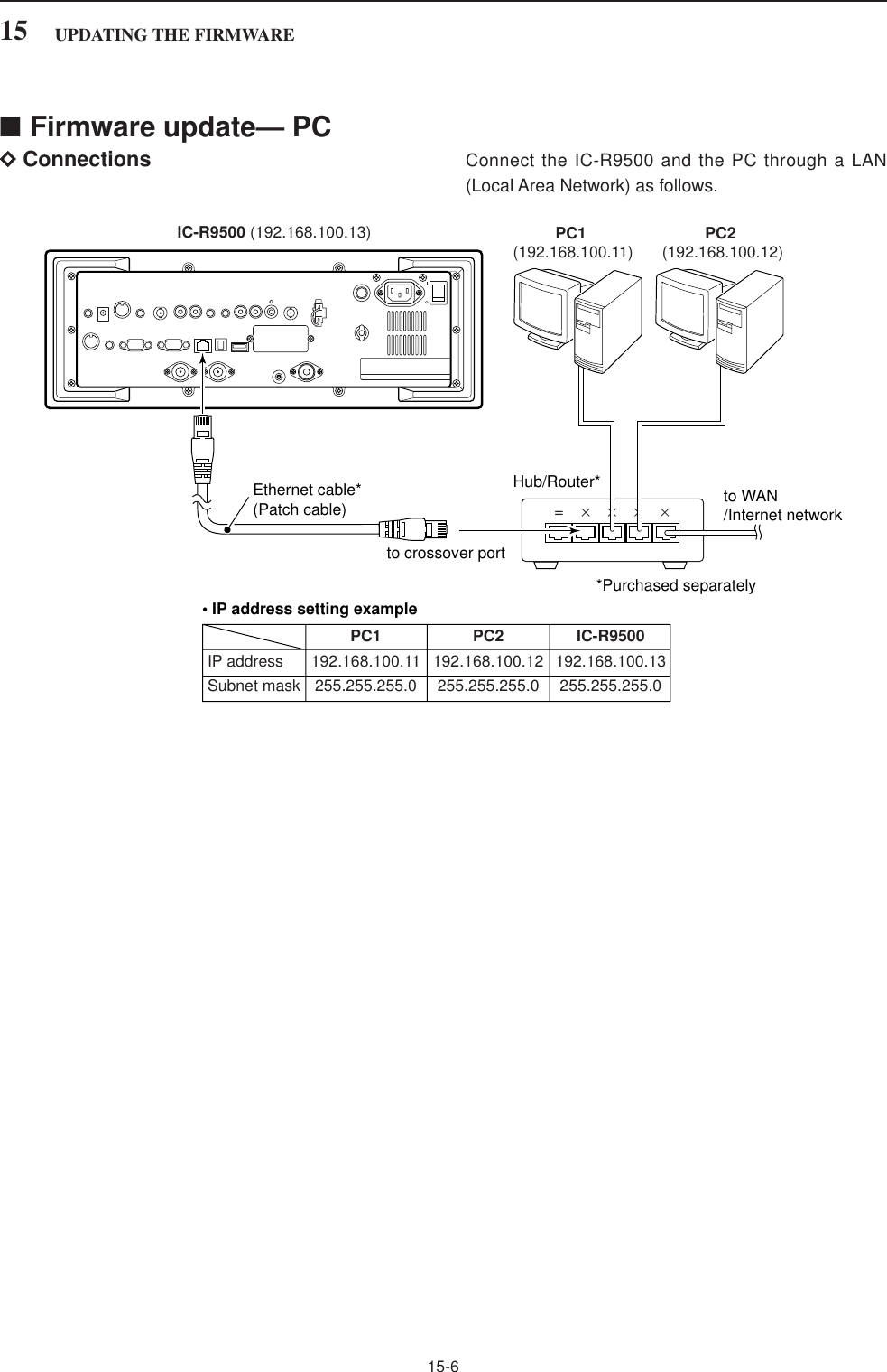
![15-4■Firmware update—USB-MemoryWhen updating the firmware with the CF card or USB-Memory, no IP address or subnet mask settings arenecessary. qCopy the downloaded firmware data into the USB-Memory (“IC-R9500” folder).• The USB-Memory must have been formatted by the IC-R9500.wInsert the USB-Memory into the USB connector.ePush [EXIT/SET] several times to close a multi-function screen, if necessary.rPush [F-7•SET] to select set mode menu screen.tPush [F-7•CF/USB] to select CF/USB-Memory setmenu.yPush and hold [F-3•FIRM UP] for 1 sec.uRead the displayed precautions carefully.• Push [F-1•Y] or [F-2•Z] to scroll the text.• Push [F-7•CANCEL] to cancel firmware updating.iAfter you read and understand all of the precau-tions, push [F-6•OK].• [F-6•OK] appears only following the precautions.• Push [F-7•CANCEL] to cancel the firmware updating.oPush [F-2•Y] or [F-3•Z] to select the firmware file,then push [F-4•FIRM UP].• Push and hold [F-1•DIR/FILE] for 1 sec. to select theUSB-Memory, if CF card is selected.!0 Read the displayed precautions carefully.!1 If you agree, push [F-6•OK] for 1 sec. to start thefirmware update.• Push [F-7•CANCEL] to cancel firmware updating.!2 While loading the firmware from the CF memorycard, the dialog at left is displayed.[EXIT/SET][F-2•Z]/[F-2•Y][F-3•FIRM UP]/[F-3•Z] [F-6•OK][F-1•Y]/[F-1•DIR/FILE][F-7•SET]/[F-7•CF/USB]/[F-7•CANCEL][F-4•FIRM UP]15 UPDATING THE FIRMWARE](https://usermanual.wiki/ICOM-orporated/284401.User-Manual-3/User-Guide-761726-Page-56.png)
![15-5!3 After firmware loading is completed, the receiverstarts the update automatically and the dialog at leftis displayed.RWARNING!: NEVER turn the IC-R9500 powerOFF at this stage.The receiver firmware will be damaged.!4 When the dialog disappears, the precaution as atleft is displayed.!5 Read the precaution carefully, and then push [F-6•OK].• Return to CF/USB-Memory set menu.!6 Push [POWER] to turn the IC-R9500 power OFF,then ON again.!7 Depending on the status of the update process, ei-ther of dialogs at left will appears in sequence.RWARNING!: NEVER turn the IC-R9500 powerOFF at this stage.The receiver firmware will be corrupted.!8 After the dialog disappears, the firmware update iscompleted and the normal operation screen ap-pears.RX-DSP UPDATING...Please wait for 20sec.WARNING! NEVER turn power OFF.Please wait for 45sec.WARNING! NEVER turn power OFF.15UPDATING THE FIRMWARE](https://usermanual.wiki/ICOM-orporated/284401.User-Manual-3/User-Guide-761726-Page-57.png)
![15-7DIP address settingIMPORTANT!: A fixed (static) IP address is used forthe IC-R9500.When you connect the IC-R9500 to a LAN, ask thenetwork manager about a usable/assignable IPaddress and the subnet mask in advance.NEVER use an IP address that has already beenallocated to another device in the network. If the IPaddress is duplicated, the network will crash.qPush [EXIT/SET] several times to close a multi-function screen, if necessary.wPush [F-7•SET] to select set mode menu screen.ePush [F-5•OTHERS] to select the others set mode.rPush [F-1•Y]/[F-2•Z] several times to select “IP Ad-dress.”tPush [F-3•Ω≈] to select the desired segment thenrotate main dial to set the desired or specified IP ad-dress.• “192.168.0.1” is the default setting.yPush [F-2•Z] to select “Subnet Mask” item.uRotate main dial to set the desired or specified sub-net mask.• “255.255.255.0” is the default setting.iPush [POWER] to turn the receiver power OFF,then ON to accept the new IP address and subnetmask settings.[EXIT/SET][F-2•Z][F-1•Y][F-3•Ω≈][F-5•OTHERS] [F-7•SET]When updating the firmware from the USB-Memory,setting the IP address is not necessary.15UPDATING THE FIRMWARE](https://usermanual.wiki/ICOM-orporated/284401.User-Manual-3/User-Guide-761726-Page-59.png)
![15-8DUpdating from the PCqStart up the IC-R9500 Firm Utility.• The window as at left appears.wRead the caution in the window carefully.eClick [Yes] if you agree and to continue the firmwareupdating.rSelect the firmware file with the “dat” extension (e.g.:9500xxxx.dat).• Click […], then select the file, as well as the location.tType the IC-R9500’s IP address into “IC-R9500 IPAddress” text box.yClick [Start].uThe window at left appears.Read the precaution in the window carefully. iClick [Yes] if you want to start the firmware update.Updating the main CPU firmware first.It will take approx. 1 minute.DO NOT turn the IC-R9500 power OFF until "Completed" dialog is displayed.Depending on the updated contents, the sub CPU and/or DSP firmware will automatically be updated when rebooting the IC-R9500 and this will take approx. 2 minutes. DO NOT turn the IC-R9500 power OFF until the normal operational screen appears, in such case.Do you wish to start the firmware update?Click to start thefirmware updateiR9500COMMUNICATIONS RECEIVERIC-R9500 IP AddressVersion 1.00(C) 2006 Icom Inc.Firmware File NameTurn the IC-R9500 power ON.When the normal operational screen appears, set the firmware file nameand IP address, then click [Start] button.IC-R9500 Firm UtilityClick […] to select the firmware file.Type the IC-R9500’s IP address here.Do you agree to all of the above?iR9500COMMUNICATIONS RECEIVERFirm Utility===CAUTION===Updating the firmware is very risky. If you make a mistake, the IC-R9500 may not operate properly, and repair at Icom Inc.(Japan) may be the only way to fix it.You undertake the updating of the firmware at you own risk and responsibility, Please refer to the firmware download homepage and/or the instruction manual for the correct procedures in updating the firmware.Also all preciously set conditions, the memory contents, etc will be lost when making a firmware update.Making a backup file of programmed contents and settings onto the CF/USB-Memory before updating is recommended.Click tocontinue15 UPDATING THE FIRMWARE](https://usermanual.wiki/ICOM-orporated/284401.User-Manual-3/User-Guide-761726-Page-60.png)
![15-9oThe screen at left is displayed.• The following dialog appears in the IC-R9500 display.RWARNING!: NEVER turn the IC-R9500 powerOFF at this stage.The receiver firmware will be corrupted.!0 Click [OK] to finish the firmware update.• The “FIRMWARE UPDATING” dialog as above disap-pears.!1 Push [POWER] to turn the IC-R9500 power OFF,then ON again.!2 Depending on the status of the update process, ei-ther of dialogs at left will appear in sequence.RWARNING!: NEVER turn the IC-R9500 powerOFF at this stage.The receiver firmware will be corrupted.!3 After the dialog disappears, the firmware update iscompleted and the normal operation screen ap-pears.RX-DSP UPDATING...Please wait for 20sec.WARNING! NEVER turn power OFF.Please wait for 45sec.WARNING! NEVER turn power OFF.Firmware up dating for the main CPU is completed.The sub CPU and/or DSP firmware update will start automatically depending on the updated contents, and this will take approx. 2 minutes.Turn the IC-R9500 power OFF, then ON again with [POWER] switch.After turning the power ON, the IC-R9500 will work with the updated firmware.DO NOT turn the IC-R9500 power OFF until the normal operational screen appears.Click [OK] to finish the firmware update.iR9500COMMUNICATIONS RECEIVERIC-R9500 IP AddressIC-R9500 IP AddressFirmware File NameVersion 1.00(C) 2006 Icom Inc.Firmware File NameConnecting to the IC-R9500.Connected to the IC-R9500.Transfer in progress...Transfer successful.Start update.Please wait a while.IC-R9500 Firm Utility15UPDATING THE FIRMWARE](https://usermanual.wiki/ICOM-orporated/284401.User-Manual-3/User-Guide-761726-Page-61.png)