ICOM orporated 288000 Communications Receiver User Manual IC PCR1500
ICOM Incorporated Communications Receiver IC PCR1500
UserManual.wiki
>
ICOM orporated
>
288000 User Manual
>
User Manual 2
Contents
1.
User Manual 1
2.
User Manual 2
User Manual 2
Navigation menu
Upload a User Manual
Namespaces
Wiki Guide
HTML
PDF
Info
Views
User Manual
Discussion / Help
Navigation
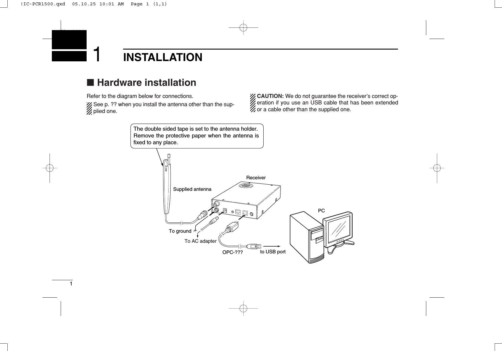
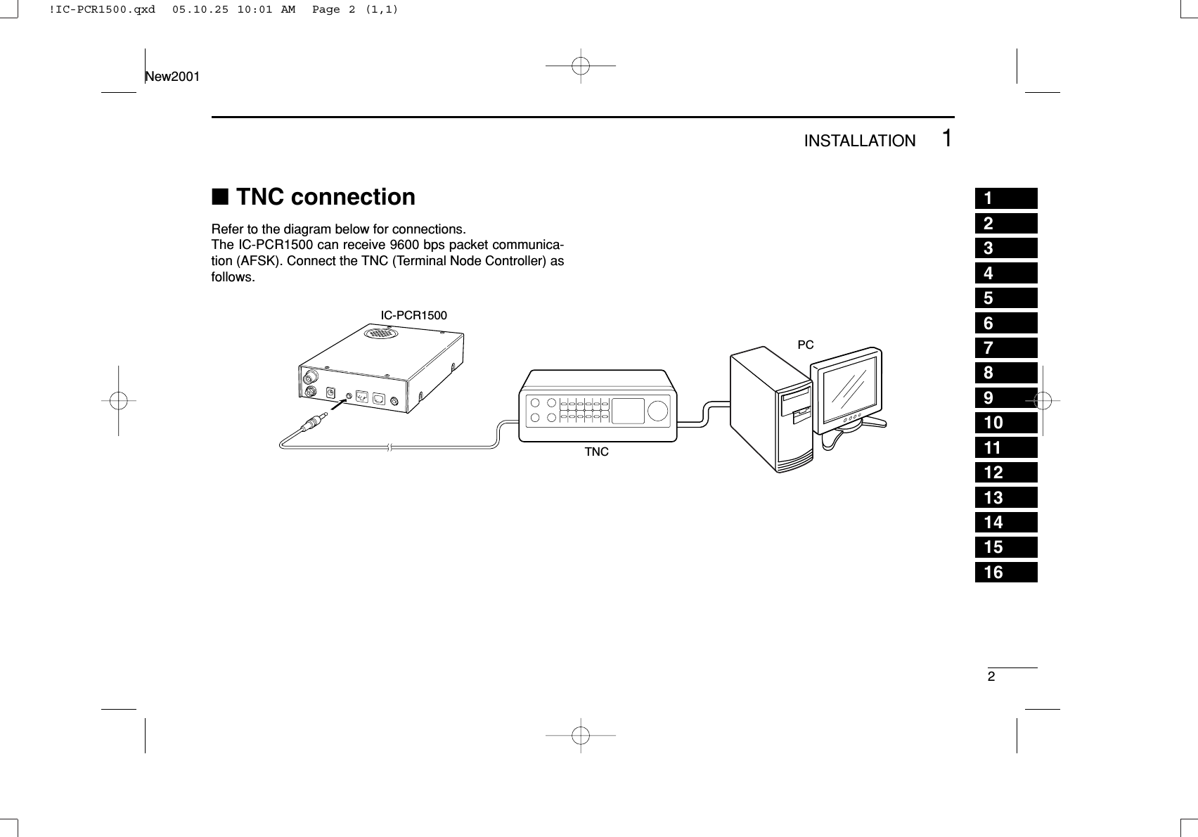
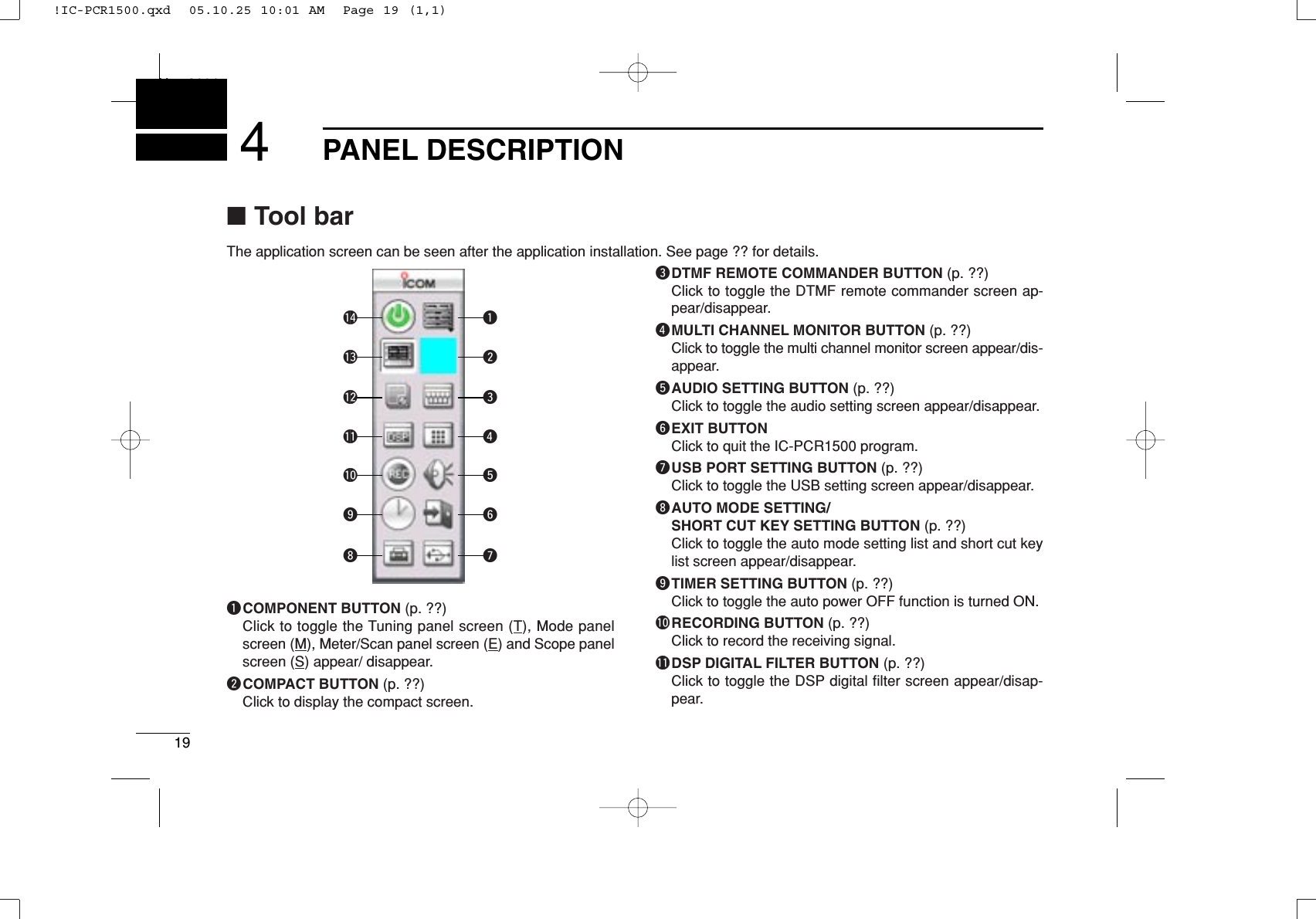
![51INSTALLATIONNew2001■Mouse property settingThe IC-PCR1500 uses left and right buttons to rotate a con-trol knob on the multi-function receiver screen or to call up theshortcut menu from the simple function receiver screen. De-pending on the mouse property setting of the control panel,main and sub mouse button functions are alternated.In this instruction manual, the operation is described withsetting for right-handed (Windows®default setting).DSetting the button configurationqSelect ‘Settings’ from the [Start] menu and click ‘ControlPanel.’wOpen the mouse control panel.eSelect the button configuration to right- or left-handed.rClick [OK] to set and exit the control panel.!IC-PCR1500.qxd 05.10.25 10:01 AM Page 5 (1,1)](https://usermanual.wiki/ICOM-orporated/288000.User-Manual-2/User-Guide-623734-Page-8.png)
![62DRIVER INSTALLATION12345678910111213141516The displayed dialog boxes or indications may differslightly from the following instructions according to yoursystem conditions, or environment.■Microsoft®Windows®XPqConnect the IC-PCR1500 to the desired USB port.• Push [POWER] to turn the power ON.• “Found New Hardware” appears as below.wThe “Found New Hardware Wizard” will come up as below.Insert the supplied CD into the CD drive, select “Install thesoftware automatically (Recommended),” then click[Next>].!IC-PCR1500.qxd 05.10.25 10:01 AM Page 6 (1,1)](https://usermanual.wiki/ICOM-orporated/288000.User-Manual-2/User-Guide-623734-Page-9.png)
![72DRIVER INSTALLATIONNew2001eThe wizard starts searching for the driver and shows thedialog below during search.rAfter the driver is found, the “Hardware Installation” dialogbox appears as below. Click [Continue Anyway] to start the installation.tWindows starts installing the USB driver.yAfter the installation is completed, click [Finish].!IC-PCR1500.qxd 05.10.25 10:01 AM Page 7 (1,1)](https://usermanual.wiki/ICOM-orporated/288000.User-Manual-2/User-Guide-623734-Page-10.png)
![82DRIVER INSTALLATIONNew200112345678910111213141516uThe “Found New Hardware Wizard” will come up again toinstall the USB serial port driver.Select “Install the software automatically (Recommended),”then click [Next>].iAfter the driver is found, the “Hardware Installation” dialogbox appears as below. Click [Continue Anyway] to start the installation.oWindows starts installing the USB driver.!IC-PCR1500.qxd 05.10.25 10:01 AM Page 8 (1,1)](https://usermanual.wiki/ICOM-orporated/288000.User-Manual-2/User-Guide-623734-Page-11.png)
![92DRIVER INSTALLATIONNew2001!0After the installation is completed, click [Finish].!1After clicking [Finish], the dialog appears as below.!2Eject the CD.• Rebooting the PC is recommended.■Microsoft®Windows®98SE/ MeqConnect the IC-PCR1500 to the desired USB port.• Push [POWER] to turn the power ON.• “New Hardware is found” dialog box appears.wThe “New Hardware Found” will come up as below. Click[Browse...].eInsert the supplied CD into the drive.rClick [Z] to select the appropriate CD-ROM drive then click“Driver” folder. After the driver is found, click [OK].!IC-PCR1500.qxd 05.10.25 10:01 AM Page 9 (1,1)](https://usermanual.wiki/ICOM-orporated/288000.User-Manual-2/User-Guide-623734-Page-12.png)
![102DRIVER INSTALLATIONNew200112345678910111213141516tClick [OK].• The driver installation starts.yAfter the installation, eject the CD.• Rebooting the PC is recommended.■Microsoft®Windows®2000qConnect the IC-PCR1500 to the desired USB port.• Push [POWER] to turn the power ON.• “Found New Hardware” dialog box appears below.wThe “Found New Hardware Wizard” will come up as below.Click [Next>].!IC-PCR1500.qxd 05.10.25 10:01 AM Page 10 (1,1)](https://usermanual.wiki/ICOM-orporated/288000.User-Manual-2/User-Guide-623734-Page-13.png)
![112DRIVER INSTALLATIONNew2001eSelect “Search for a suitable driver for my device (recom-mended),” then click [Next>].rSelect “CD-ROM drives,” and insert the supplied CD intothe CD drive, then click [Next>].!IC-PCR1500.qxd 05.10.25 10:01 AM Page 11 (1,1)](https://usermanual.wiki/ICOM-orporated/288000.User-Manual-2/User-Guide-623734-Page-14.png)
![122DRIVER INSTALLATIONNew200112345678910111213141516tWhen the driver is found, the following dialog is displayed.Click [Next>] to start the installation.NOTE: When the appropriate driver is not found, a differ-ent dialog is displayed. In such case, click [<Back], select“Specify a location,” click [Next>], then type “D:\driver” inthe text box to select the “Driver” folder in the CD (if CDdrive is D).yAfter the installation is completed, click [Finish].uThe “Found New Hardware” wizard appears again.!IC-PCR1500.qxd 05.10.25 10:01 AM Page 12 (1,1)](https://usermanual.wiki/ICOM-orporated/288000.User-Manual-2/User-Guide-623734-Page-15.png)
![132DRIVER INSTALLATIONNew2001iClick [Next>]. oSelect “Search for a suitable driver for my device (recom-mended),” then click [Next>].!IC-PCR1500.qxd 05.10.25 10:01 AM Page 13 (1,1)](https://usermanual.wiki/ICOM-orporated/288000.User-Manual-2/User-Guide-623734-Page-16.png)
![142DRIVER INSTALLATIONNew200112345678910111213141516!0Select “CD-ROM drives,” then click [Next>]. !1When the driver is found, the following dialog is displayed.Click [Next>] to start the installation.NOTE: When the appropriate driver is not found, a differ-ent dialog is displayed. In such case, click [<Back], select“Specify a location,” click [Next>], then type “D:\driver” inthe text box to select the “Driver” folder in the CD (if CDdrive is D).!IC-PCR1500.qxd 05.10.25 10:01 AM Page 14 (1,1)](https://usermanual.wiki/ICOM-orporated/288000.User-Manual-2/User-Guide-623734-Page-17.png)
![152DRIVER INSTALLATIONNew2001!2After the installation is completed, click [Finish].!3Eject the CD.• Rebooting the PC is recommended.■COM port confirmationAfter the driver installation, confirm the driver availability andthe port number are recommended.In this section, screen shots of Windows XP are used for in-struction example. However, the instructions are similar to an-other operating systems, Windows 98SE, Me and 2000.qBoot up the Windows.wSelect the “Control Panel” in the Start menu.• Control panel appears as shown in the next step below.eClick the “Performance and Maintenance.” • Performance and Maintenance menu appears.rClick the “System,” then click the “Hardware” tab in the dis-played System Properties screen.!IC-PCR1500.qxd 05.10.25 10:01 AM Page 15 (1,1)](https://usermanual.wiki/ICOM-orporated/288000.User-Manual-2/User-Guide-623734-Page-18.png)
![162DRIVER INSTALLATIONNew200112345678910111213141516tClick the [Device Manager]. • Device Manager screen appears as below.yClick “ ” of the “Ports (COM & LPT)” to display the usableCOM port and the port number.uConfirm the USB serial port availability and the COM portnumber.• The COM port number is used for the COM port setup. (p. ??)iClose the Device Manager, System Properties screen andthen Control panel.!IC-PCR1500.qxd 05.10.25 10:01 AM Page 16 (1,1)](https://usermanual.wiki/ICOM-orporated/288000.User-Manual-2/User-Guide-623734-Page-19.png)
![17APPLICATION INSTALLATIONNew20013qInsert the CD into the CD drive.wOpen the CD drive contents via “My computer” or “Win-dows Explorer.”• “Driver” and “ICPCR1500” folders are available.eDouble click “Setup.exe” file in “IC-PCR1500” folder.• The “InstallShield®Wizard” starts preparing the installation.rAfter the preparation, the following dialog is displayed.Click [Next>].!IC-PCR1500.qxd 05.10.25 10:01 AM Page 17 (1,1)](https://usermanual.wiki/ICOM-orporated/288000.User-Manual-2/User-Guide-623734-Page-20.png)
![183APPLICATION INSTALLATIONNew200112345678910111213141516tConfirm the location, then click [Next>] to start the installa-tion.• Click [Browse...] then type the desired location if you specifyingthe installation location.yAfter the installation is completed, click [Finish].uEject the CD.• The IC-PCR1500 shortcut icon is created on the desktop.• Rebooting the PC is recommended.!IC-PCR1500.qxd 05.10.25 10:01 AM Page 18 (1,1)](https://usermanual.wiki/ICOM-orporated/288000.User-Manual-2/User-Guide-623734-Page-21.png)
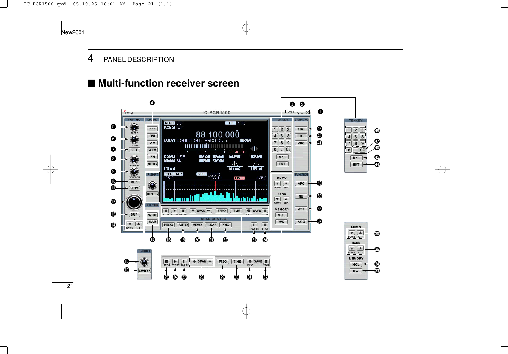
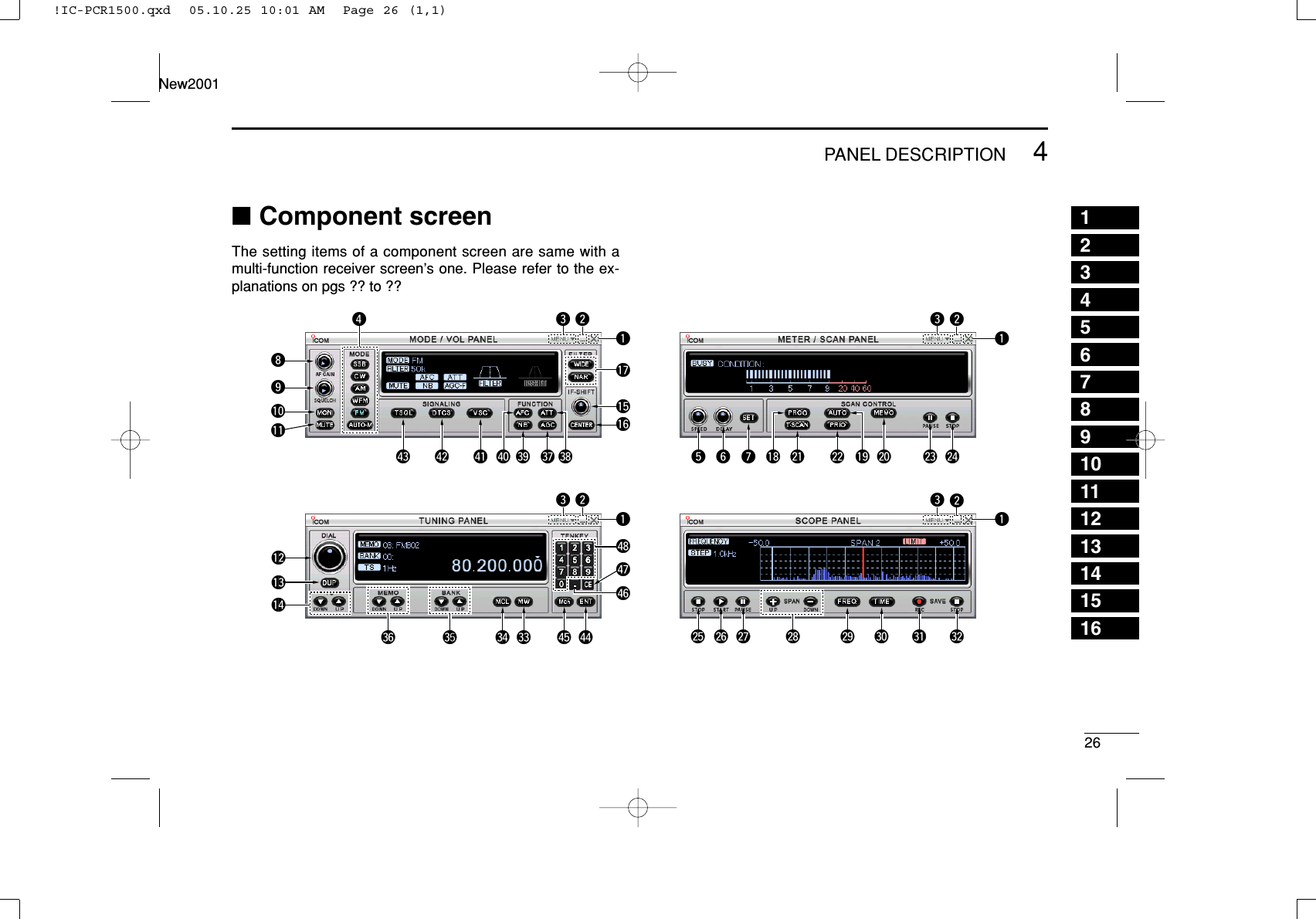
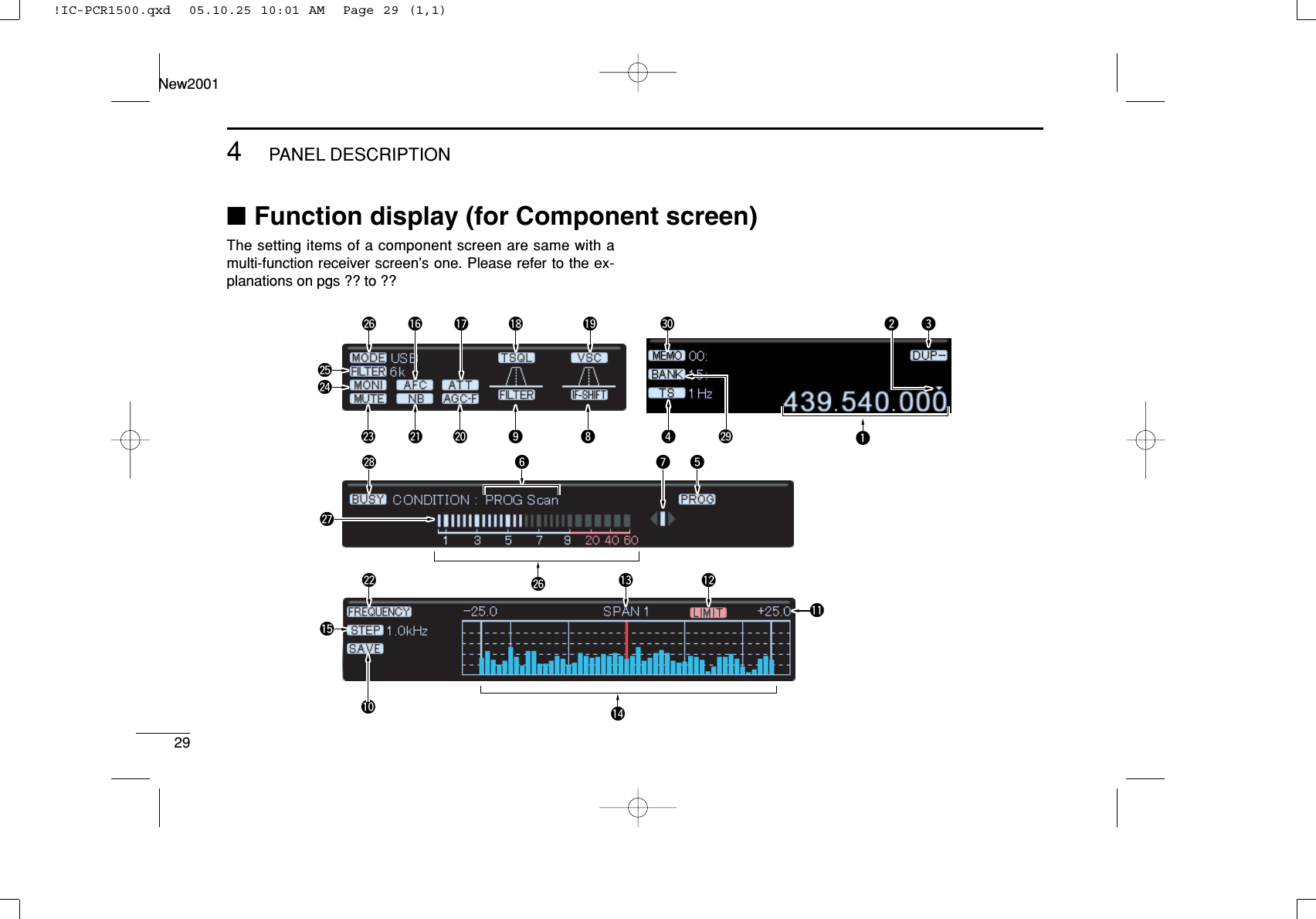
![224PANEL DESCRIPTIONNew200112345678910111213141516qCLOSE BUTTONClick to quit and exit the application screen.wMINIMIZE BUTTONClick to minimize the application screen.eMENU LISTClick to display the menu list to perform the following oper-ation.• Turning the receiver power ON/OFF• Creating a new file• Opening a file• Saving (over-write or with different file name) the set con-tents.• Quitting the applicationrRECEIVE MODE BUTTONS [SSB], [CW], [AM], [WFM],[FM], [AUTO-M] (pgs. ??, ??)Click to select a receive mode.• When using [AUTO-M] (automatic mode), a receive mode, IFfilter passband width, tuning step, etc., are selected automaticallyafter inputting a frequency. (p. ??)tSCAN SPEED CONTROL [SPEED] (p. ??)Click to set the speed at which scans search through fre-quencies/memories for signals.• Right-click to increase the speed level.• Left-click to decrease the speed level.ySCAN DELAY TIME CONTROL [DELAY] (p. ??)Click to set the period in which a scan pauses after receiv-ing a signal.• Right-click to increase the period.• Left-click to decrease the period.uSET BUTTON [SET]Click to show the [Scan Delay] screen.This screen is used for the settings of the scan function,band scope function, the automatic mode select function,etc.iAUDIO FREQUENCY GAIN CONTROL [AF GAIN]Click to adjust the audio output level.• Right-click to increase the audio output level.• Left-click to decrease the audio output level.oSQUELCH CONTROL [SQUELCH] (p. ??)Click to adjust the squelch threshold level.The squelch removes noise output from the speaker(closed condition) when no signal is received.• Right-click to close the squelch.• Left-click to open the squelch.!0MONITOR BUTTON [MONI] (p. ??)Click to turn the monitor function ON or OFF.The monitor function is used to temporarily open thesquelch to listen to weak signal.!1MUTE BUTTON [MUTE] (p. ??)Click to turn the mute function ON or OFF.This function is used to temporarily mute audio output.!IC-PCR1500.qxd 05.10.25 10:01 AM Page 22 (1,1)](https://usermanual.wiki/ICOM-orporated/288000.User-Manual-2/User-Guide-623734-Page-25.png)
![234PANEL DESCRIPTIONNew2001■Multi-function receiver screen (Continued)!2TUNING DIAL (p. ??)Click to set the receive frequency with the selected tuningstep.• Right-click to increase the frequency.• Left-click to decrease the frequency.!3DUPLEX BUTTON [DUP] (p. ??)➥Right-click to display the offset frequency setting screen.➥Left-click to set the duplex direction from OFF (noindication), DUP –, and DUP +.!4TUNING STEP UP/DOWN BUTTONS [Y]/[Z](p. ??)➥Right-click to display the tuning step setting screen.➥Left-click to select the tuning steps in order.!5IF-SHIFT CONTROL (p. ??)Click to set a signal passband position.• Right-click to increase the signal passband position.• Left-click to decrease the signal passband position.!6CENTER KEY [CENTER] (p. ??)After moving a signal passband position with clicking theIF-shift control, click to return to the center position.!7IF FILTER BUTTONS [WIDE]/[NAR] (p. ??)Click to change the IF filter in use.• Click [WIDE] to select a wide filter.• Click [NAR] to select a narrow filter.*Usable IF filter is according to the receive mode.!8PROGRAMMED SCAN BUTTON [PROG] (p. ??)Click to start/stop a programmed scan.• “PROG Scan” blinks during scanning.!9AUTO MEMORY WRITE SCAN BUTTON [AUTO] (p. ??)Click to start/stop an auto memory write scan.• “AUTO Scan” blinks during scanning.@0MEMORY SCAN BUTTON [MEMO] (p. ??)Click to start/stop a memory scan.• “MEMO Scan” blinks during scanning.@1TONE SCAN BUTTON [T-SCAN] (p. ??)Click to start/stop a tone scan.• “TONE Scan” blinks during scanning.@2PRIORITY SCAN BUTTON [PRIO] (p. ??)Click to start/stop a priority scan.• “PRIO Scan” blinks during scanning.@3WEATHER ALERT BUTTON [WX] (p. ??)Push to start the weather alert function.@3SCAN PAUSE BUTTON [PAUSE] (p. ??)Push to pause/resume a scan.• “Pause” blinks during scan is pausing.@4SCAN STOP BUTTON [STOP] (p. ??)Push to cancel a scan operation.@5SWEEP STOP BUTTON [■](p. ??)Click to stop a band scope function.@6SWEEP START BUTTON [≈≈](p. ??)Click to start the band scope function which is used toobserve signal conditions around the receive frequency.!IC-PCR1500.qxd 05.10.25 10:01 AM Page 23 (1,1)](https://usermanual.wiki/ICOM-orporated/288000.User-Manual-2/User-Guide-623734-Page-26.png)
Click to pause/resume a band scope sweeping.NOTE: While using the band scope function, audio isnot output. To monitor the frequency, push [❙❙] to pausethe function, or push [■] to cancel the function.@8SPAN (TIME) UP/DOWN BUTTON [Y]/[Z](p. ??)When “FREQUENCY” table is displayed;Click to select the band scope edge frequency.When “TIME” table is displayed;Click to select the time interval to show the receivingsignal.@9FREQUENCY BUTTON [FREQ]Click to show the receiving signal relative to signalstrength.#0TIME BUTTON [TIME]Click to show the receiving signal condition on that time.#1REC BUTTONClick to start recording of the receiving signal contents.#2STOP BUTTONClick to stop recording.#3MEMORY WRITE BUTTON [MW] (p. ??)Click to write the current receive frequency into theselected memory channel.#4MEMORY CLEAR BUTTON [MCL] (p. ??)Click to clear the unneeded (displayed??) memory channelcontents.#5BANK UP/DOWN BUTTONS [Y]/[Z](p. ??)Click to change the memory bank.#6MEMORY CHANNEL UP/DOWN BUTTONS [Y]/[Z](p. ??)Click to change a memory channel.#7AUTOMATIC GAIN CONTROL BUTTON [AGC] (p. ??)Click to turn the AGC (Automatic Gain Control) function ONor OFF.• “AGC” appears when the AGC function is turned ON.#8ATTENUATOR BUTTON [ATT] (p. ??)Click to turn the ATT (Attenuator) function ON or OFF.• “ATT” appears when the ATT function is turned ON.#9NOISE BLANKER BUTTON [NB] (p. ??)Click to turn the NB (Noise Blanker) function ON or OFF.• “NB” appears when the NB function is turned ON.$0AUTOMATIC FREQUENCY CONTROL BUTTON [AFC](p. ??)Click to turn the AFC (Automatic Frequency Control)function ON or OFF.• “AFC” appears when the AFC function is turned ON.!IC-PCR1500.qxd 05.10.25 10:01 AM Page 24 (1,1)](https://usermanual.wiki/ICOM-orporated/288000.User-Manual-2/User-Guide-623734-Page-27.png)
![254PANEL DESCRIPTIONNew2001■Multi-function receiver screen (Continued)$1VOICE SCAN CONTROL BUTTON [VSC] (p. ??)Click to turn the VSC (Voice Scan Control) function ON orOFF.• “VSC” appears when the VSC function is turned ON.$2DTCS SETTING BUTTON [DTCS] (p. ??)➥Click to display the DTCS code setting screen, then click[Z]to select the desired code.➥Click the polarity radio button to select the polarity fromNormal or Reverse.• Available only when FM mode is selected.• “DTCS” appears when the DTCS code and polarity are set.• Click again to cancel the DTCS setting.$3CTCSS SETTING BUTTON [TSQL] (p. ??)Click to display the tone squelch frequency setting screen,then click [Z]to select the desired frequency.• Available only when FM mode is selected.• “CTCSS” appears when the tone squelch frequency is set.• Click again to cancel the CTCSS setting.$4ENTER KEY [ENT]Click to enter the frequency when the desired receivefrequency is input via the 10 keypad.$5MEMORY CHANNEL KEY [Mch]Click to call the memory channel when the desired channelnumber is input via the 10 keypad.$6TENKEY— DECIMAL BUTTON [.]Click to set the MHz digit when inputting a frequency viathe 10 keypad.$7TENKEY— CLEAR BUTTON [CE]Click to clear the mistake while inputting a receivefrequency or memory channel number via the 10 keypad.$8TENKEY— NUMERAL BUTTONS [1] to [0]The numeral buttons can be used for several functions asbelow:• Direct receive frequency input.• Memory channel input.!IC-PCR1500.qxd 05.10.25 10:01 AM Page 25 (1,1)](https://usermanual.wiki/ICOM-orporated/288000.User-Manual-2/User-Guide-623734-Page-28.png)
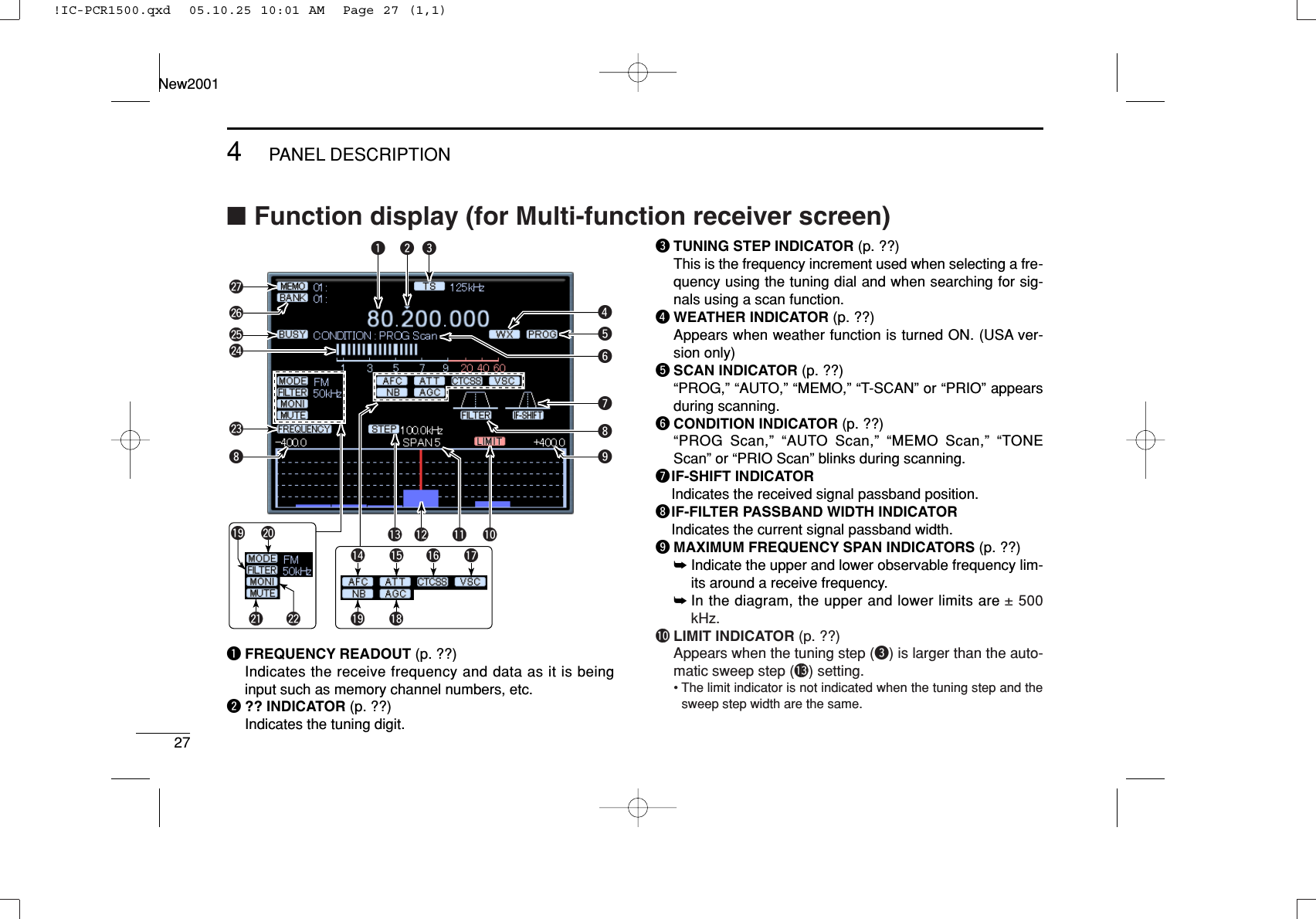
![284PANEL DESCRIPTIONNew200112345678910111213141516!1 FREQUENCY SPAN INDICATOR (p. ??)Indicates the frequency span selected with the [SPAN Y]or [SPAN Z] button.!2 CENTER FREQUENCY INDICATOR (p. ??)Indicates the center frequency of the frequency span; thisis for the currently received frequency.!3 SWEEP STEP INDICATOR (p. ??)Indicates band scope sweep step.!4AFC INDICATOR [AFC] (p. ??)Appears when the AFC (Automatic Frequency Control)function is ON.!5 ATTENUATOR INDICATOR [ATT] (p. ??)Appears when the ATT (Attenuator) function is ON.!6CTCSS/DTCS INDICATOR [CTCSS]/[DTCS] (p. ??)➥“CTCSS” appears when the tone squelch frequency is set.➥“DTCS” appears when DTCS code and the polarity are set.!7VSC INDICATOR [VSC] (p. ??)Appears when the VSC (Voice Scan Control) function is ON.!8NB INDICATOR [NB] (p. ??)Appears when the NB (Noise Blanker) function is ON.!9AGC INDICATOR [AGC] (p. ??)Appears when the AGC (Automatic Gain Control) functionis ON.@1 IF FILTER INDICATOR (p. ??)Indicates the selected IF filter.@2 RECEIVE MODE INDICATORS (p. ??)Indicate the current receive mode.• “WFM” lights in red when receiving a stereo broadcast program.@1 MUTE INDICATOR (p. ??)Appears when the squelch circuit mute the received audiosignal.@1 MONI INDICATOR (p. ??)Appears during monitoring the operating frequency.@0 FREQUENCY/TIME INDICATOR [FREQUENCY]/[TIME](p. ??)➥“FREQUENCY” appears when the receiving signalrelative to signal strength is displayed.➥“TIME” appears when the receiving signal condition onthat time is displayed.@3 S (SIGNAL) METER (pgs. ??, ??)Indicates the receive signal strength. Also indicates theS-meter squelch receive level set via the [SQUELCH] con-trol.@4 BUSY INDICATOR [BUSY]Appears when receiving a signal or when signal noiseopens the squelch.@5 MEMORY BANK INDICATOR (p. ??)Indicates the memory bank number (and name if it is set)being received.@6 MEMORY CHANNEL INDICATOR (p. ??)Indicates the memory channel number (and name if it isset) being received.• The name darkens when the receive frequency changes fromthe stored one.!IC-PCR1500.qxd 05.10.25 10:01 AM Page 28 (1,1)](https://usermanual.wiki/ICOM-orporated/288000.User-Manual-2/User-Guide-623734-Page-31.png)
![304PANEL DESCRIPTIONNew200112345678910111213141516■Rear PanelqANTENNA CONNECTOR [ANT]Connects a 50 Ωantenna with a BNC connector and a 50Ωcoaxial cable.wEXTERNAL SPEAKER JACK [EXT SP]Connects an 8 Ωexternal speaker.• Audio output power is more than 0.5 W.eUSB RECEPTACLE [USB]Connects to a PC via an extension cable.rCONTROLLER [CONTROLLER]Connects to a controller via an extension cable.tDATA SOCKET [PACKET]Connects a TNC (Terminal Node Controller), etc. for datacommunications. The receiver can receive 9600 bpspacket communication (AFSK.)• See p. ? for connection information.yPOWER RECEPTACLE [DC IN]Accepts 12 V DC ±15% with the supplied DC power cable.☞NOTE: DO NOT use a cigarette lighter socket as apower source when operating in a vehicle. The plugmay cause voltage drops and ignition noise may be su-perimposed onto receive audio.uGROUND TERMINAL [GND]Connect this terminal to a ground.quy t r ew!IC-PCR1500.qxd 05.10.25 10:01 AM Page 30 (1,1)](https://usermanual.wiki/ICOM-orporated/288000.User-Manual-2/User-Guide-623734-Page-33.png)
![31BASIC OPERATIONNew2001New20015■Launching the IC-PCR1500qBefore launching the IC-PCR1500 program, make sure thereceiver’s power ON. Then launch the IC-PCR1500 pro-gram. (p. ??)wClick “ ” on the tool bar to turn the IC-PCR1500 ON.eClick the desired icon (multi-function receiver, componentor simple) on the tool bar to select the receiver screen thatyou want to use.■Changing the receiver screenClick the desired tool bar icon that you want to use.• Click [Receiver] for the multi-function receiver screen.• Click [Comp] for the component screen.• Click [Simple] for the simple screen.!IC-PCR1500.qxd 05.10.25 10:01 AM Page 31 (1,1)](https://usermanual.wiki/ICOM-orporated/288000.User-Manual-2/User-Guide-623734-Page-34.png)
![325BASIC OPERATION12345678910111213141516New2001■Closing the IC-PCR1500DUsing the multi-function receiver screen orcomponent screenClick [Close] in the menu list, or close button ([X]) to quit theIC-PCR1500 program.• Click [Close] in the menu list, or close button (X) in each [TUNINGPANEL], [MODE/VOL PANEL], [METER/SCAN PANEL] and[SCOPE PANEL] when the component screen is displayed.DSimple screenClick ■Quitting the IC-PCR1500DUsing the multi-function receiver screen orcomponent screenClick “ ” on the tool bar or [Power OFF] in the menu list toquit the IC-PCR1500.DSimple screenClick !IC-PCR1500.qxd 05.10.25 10:01 AM Page 32 (1,1)](https://usermanual.wiki/ICOM-orporated/288000.User-Manual-2/User-Guide-623734-Page-35.png)
![335BASIC OPERATIONNew2001■ReceivingMake sure the hardware installation is finished. (p. ??)DUsing the multi-function receiver screen orcomponent screenqClick “ ” to turn power ON.wClick [AF GAIN] to set the audio level.• Right-click to increase the audio level.• Left-click to decrease the audio level.• When clicking and holding [AF GAIN], the audio level scrolls upor down.• Push the PC‘s [↑] (UP) or [↓] (DOWN) key also sets the audiolevel.eClick [SQUELCH] to set the squelch level.• Right-click to increase the squelch level (tight squelch).• Left-click to decrease the squelch level (loose squelch).• When clicking and holding [SQUELCH], the squelch level scrollsup or down.rSet the receive frequency and mode. (pgs. ??, ??)tWhen receiving a signal on the set frequency, squelchopens and the receiver emits audio.• “BUSY” appears and the S-meter indicator shows the relativesignal strength for the received signal.■Setting a frequencyDepending on the situation, the receive frequency can be setusing the following methods. Frequencies can be set from0.01000 to 3299.00000 MHz.DUsing the tuning dial➥Click [DIAL] to set the receive frequency with the selectedtuning step.• Right-click to increase the frequency.• Left-click to decrease the frequency.• The frequency changes according to the preset tuning steps. Seep. ?? for selecting the tuning step.• When clicking and holding either button the frequency scrolls upor down.DUsing the 10-keypad➥Click the desired numeral buttons, then click [ENT] to setthe frequency.• When making a mistake while inputting a frequency, click [CE] toclear the input and return to the previous frequency.• When you want to change the 100 kHz digit and below, click [•]first, then the numeral buttons and then [ENT].• When you want to set the 100 kHz digit and below to 0, input theMHz digits and then click [ENT].• When inputting a frequency outside of the allowed receive fre-quency range, the previously selected frequency is automaticallyselected after clicking [ENT].!IC-PCR1500.qxd 05.10.25 10:06 AM Page 33 (1,1)](https://usermanual.wiki/ICOM-orporated/288000.User-Manual-2/User-Guide-623734-Page-36.png)
![345BASIC OPERATIONNew200112345678910111213141516DUsing the PC keyboard➥Push the desired numeral keys on the PC keyboard, thenpush [Enter] to set the frequency.• When inputting from the keyboard, click anywhere in the receiverscreen first, then begin inputting from the keyboard.• When making a mistake while inputting a frequency, click [CE]on the receiver screen to clear the input and return to the previ-ous frequency.• When you want to change the 100 kHz digit and below, push [•]first, then the numeral keys and then [Enter].• When you want to set the 100 kHz digit and below to 0, input theMHz digits and then push [Enter].• When inputting a frequency outside of the allowed receive fre-quency range, the previously selected frequency is automaticallyselected after clicking [Enter].■Squelch level settingThe squelch function sets a minimum receive signal levelbelow which no audio is emitted from the speaker. This con-veniently prevents noise and static from being emitted whenreceiving weak signals or no signals at all.Further setting of squelch removes weak signals. The removelevel is displayed on the S-meter (S-meter squelch). Thesquelch does not open if a signal below the set S-meter levelis received.DUsing the multi-function receiver screen orcomponent screen➥Click [SQUELCH] to set the squelch level.• Right-click to increase the squelch level (tight squelch).• Left-click to decrease the squelch level (loose squelch).• When clicking and holding [SQUELCH], the audio level scrollsup or down.• The S-meter squelch level is displayed in the function display.DUsing the simple function receiver screenqClick [MENU] and select the ‘Function controller’ when itis not displayed.wClick [SQL J] or [SQL K] on the function controller to se-lect the desired squelch level.• The S-meter squelch level is displayed under the frequency in-dication.!IC-PCR1500.qxd 05.10.25 10:01 AM Page 34 (1,1)](https://usermanual.wiki/ICOM-orporated/288000.User-Manual-2/User-Guide-623734-Page-37.png)
![355BASIC OPERATIONNew2001■Setting a tuning stepWhen using the tuning dial to change the frequency, or whena scan function is activated, the frequency changes in incre-ments determined by the set tuning step. This can bechanged if desired.The following tuning step are available.• 1 Hz • 10Hz • 20 Hz • 50 Hz • 100 Hz• 500Hz • 1 kHz • 2.5 kHz • 5 kHz • 6.25 kHz• 8.33 kHz • 9 kHz • 10 kHz • 12.5 kHz • 15 kHz• 20 kHz • 25 kHz • 30 kHz • 50 kHz • 100 kHz• 125 kHz • 150 kHz • 200 kHz • 500 kHz • 1 MHz• 10 MHz • USER**When “USER” is selected, the tuning step, set in “USER TS Setting”screen, is selected.DTuning step selection➥Right-click [TS YY]or [TS ZZ]to display a tuning step list,then select the desired tuning step.➥Left-click [TS YY]or [TS ZZ]to set the desired tuning step inorder.• The selected tuning step is displayed in the function display.DSetting the user tuning step➥Right-click [TS YY]or [TS ZZ]to display a tuning step list,then select “USER TS Setting.” You can edit the desiredtuning step from 0.001 kHz–9999.998 kHz (in 0.001 step)directly.■Receive mode selectionReceive modes are determined by the physical properties ofthe radio signals. The receiver has 6 receive modes: SSBLSB, CW, AM, WFM and FM modes. The mode selection isstored independently in each memory channels.Typically, AM mode is used for the AM broadcast stations(0.495–1.620 MHz) and air band (118–135.995 MHz), andWFM is used for FM broadcast stations (76–107.9 MHz).When using [AUTO-M] (automatic mode), a receive mode, IFfilter passband width, tuning step, etc., are selectedautomatically after inputting a frequency. (p. ??)➥Click [SSB], [CW], [AM], [WFM], [FM] or [AUT-M] to selectthe desired receive mode.• Clicking [SSB] toggles the USB and LSB mode.!IC-PCR1500.qxd 05.10.25 10:01 AM Page 35 (1,1)](https://usermanual.wiki/ICOM-orporated/288000.User-Manual-2/User-Guide-623734-Page-38.png)
![365BASIC OPERATIONNew200112345678910111213141516■Automatic mode selectionAn automatic mode function is available to automatically setthe receive mode, IF filter passband width, tuning step, etc.after inputting a frequency.Each click of the [AUTO-M] button toggles the automaticmode function ON and OFF.DSetting the automatic mode functionThe default setting for the automatic mode function can beadded to, changed or deleted. Up to 20 ranges can be mem-orized into the automatic mode function settings.qClick “ ” on the tool bar to call up the [Setting] screen if itis not displayed.wClick the [Auto Mode] tab to display the automatic modelist.eClick a cell in the [Freq Low] column and the desired line.rInput the lower frequency of the frequency range from thekeyboard, then push [Enter].• When nothing is input into the [Freq Low] or [Freq High] column,settings for other columns cannot be made.• When inputting a new frequency, other data automatically ap-pears in the other column.• To delete a frequency range setting, enter [0] or [Space] into the[Freq Low] column from the keyboard.tInput the higher frequency of the frequency range into the[Freq High] column, push the [Enter] key.ySet other data such as mode, tuning step, etc., if desired.• Double-click the desired cell, select the desired item and double-click the selection.uClick the close button ([X]) to close the setting screen.!IC-PCR1500.qxd 05.10.25 10:01 AM Page 36 (1,1)](https://usermanual.wiki/ICOM-orporated/288000.User-Manual-2/User-Guide-623734-Page-39.png)
![375BASIC OPERATIONNew2001■Monitor functionThis function is used to listen to weak signals without disturb-ing the squelch setting or to open the squelch manually evenwhen mute functions such as the tone squelch are in use.➥Click [MONI] to monitor the operating frequency.• “MONI” appears.■Mute functionThis function is used to mutes the received audio signal.➥Click [MUTE] to temporarily mute audio output.• “MUTE” appears.!IC-PCR1500.qxd 05.10.25 10:01 AM Page 37 (1,1)](https://usermanual.wiki/ICOM-orporated/288000.User-Manual-2/User-Guide-623734-Page-40.png)

![39OTHER FUNCTIONSNew2001New20016■Duplex operationDuplex communication uses 2 different frequencies for trans-mitting and receiving. Generally, duplex is used in communi-cation through a repeater, some utility communications, etc.During duplex operation, the transmit station frequency isshifted from the receive station frequency by the offset fre-quency. Repeater information (offset frequency and shift di-rection) can be programmed into memory channels. (p. ??)qSet the receive frequency (repeater output frequency).tRight-click [DUP] to display the offset frequency settingscreen.ySet the desired offset frequency within 0.000000–1000.000000 MHz range, then click [OK].wLeft-click [DUP] to set the duplex direction from OFF (noindication,) DUP–, or DUP+.eClick [MONI] to monitor the transmit station frequency (re-peater input frequency). The displayed frequency shifts the offset frequency whenmonitor function is in use.■IF filter selectionIncreasing or decreasing the width of incoming signals canhelp eliminate interference. Available filters vary according tothe receive mode. See the table below.K: Available; –: Not available➥Click the [WIDE] or [NAR] buttons to toggle between filterwidths.■Attenuator functionStrong signals (such as from broadcast stations, pocket beep-ers, nearby amateur radio stations, etc.) can cause distortionof receive signals. The attenuator function can reduce signalstrength of interfering signals by approx. 20 dB.➥Click [ATT] to turn the ATT (Attenuator) function ON orOFF.• “ATT” appears when the ATT function is turned ON.2.8 kHz 6 kHzIF filter 15 kHz 50 kHzKAM K—KK230 kHzKUSB/LSB K————FM KKK —KCW K————WFM — — KK!IC-PCR1500.qxd 05.10.25 10:01 AM Page 39 (1,1)](https://usermanual.wiki/ICOM-orporated/288000.User-Manual-2/User-Guide-623734-Page-42.png)
![406OTHER FUNCTIONS12345678910111213141516New2001■AFC functionThe AFC (Automatic Frequency Control) function tunes thedisplayed frequency automatically when an off-center fre-quency is received. It activates in FM/WFM modes only.➥Click [AFC] to turn the AFC (Automatic Frequency Control)function ON or OFF.• “AFC” appears when the AFC function is turned ON■NB functionThe NB (noise blanker) function removes pulse-type noisewhen USB, LSB, CW or AM mode is selected.➥Click [NB] to turn the NB (noise blanker) function ON or OFF.• “NB” appears when the NB function is turned ON.■AGC functionThe AGC (Automatic Gain Control) function controls receivergain to produce a constant audio output level even when thereceived signal strength is varied by fading, etc.➥Click [AGC] to turn the AGC (Automatic Gain Control) func-tion ON or OFF.• “AGC” appears when the AGC function is turned ON.■VSC functionWhen the VSC (Voice Scan Control) function is ON, the re-ceived signals while scanning or when selecting a station andwhich open the squelch but are not modulated (contain novoice or music, etc. components) are muted. The BUSY indi-cator still lights even no audio is emitted.➥Click [VSC] to turn the VSC (Voice Scan Control) functionON or OFF.• “VSC” appears when the AFC function is turned ON.■IF shift functionThe IF shift function electronically changes the center of theIF (intermediate frequency) passband frequency to reject in-terference. It activates in SSB/CW modes only.qAdjust the [SHIFT] control for a minimum interference sig-nal level.• The audio tone may be changed while the IF shift is in use.wSet the shift control to its center position when there is nointerference.!IC-PCR1500.qxd 05.10.25 10:01 AM Page 40 (1,1)](https://usermanual.wiki/ICOM-orporated/288000.User-Manual-2/User-Guide-623734-Page-43.png)
![41MEMORY CHANNELSNew2001New20017■GeneralThe receiver has 2600 memory channels for storage of often-used frequencies. Total of 26 memory banks are available forusage by group, etc., and 100 channels are assigned into abank.DMemory channel contentsThe following information can be programmed into memorychannels:• Memory channel name • Operating frequency (p. ??)• Duplex direction (p. ??)• Offset frequency (p. ??)• Receive mode (p. ??)• IF filter selection (p. ??)• Attenuator ON/OFF (p. ??)• Tuning step (p. ??)• Select memory scan setting (p. ??)• Memory skip scan setting (p. ??)• Squelch control system ON/OFF and it’s frequency orcode (p. ??)• Remark (memory channel comment) (p. ??)■Bank name programmingEach memory bank can be programmed with an alphanu-meric bank name for easy recognition and can be indicatedindependently. Names can be a maximum of 20 characters.qClick “ ” on the tool bar to call up the [Memory ChannelEditor] screen if it is not displayed.wClick [YY]or [ZZ]to select a memory bank.eClick the bank name dialog box.• A cursor starts blinking.rProgram the desired bank name (up to 20-character) fromthe PC keyboard, then push [Enter].• The programmed name is displayed on the function display.tAfter programming, click close button ([X]) to close thememory channel list screen.!IC-PCR1500.qxd 05.10.25 10:01 AM Page 41 (1,1)](https://usermanual.wiki/ICOM-orporated/288000.User-Manual-2/User-Guide-623734-Page-44.png)
![427MEMORY CHANNELS12345678910111213141516New2001■Memory channel selectionDUsing the YY/ZZbutton on the multi-functionreceiver screen or component screenqClick [BANK YY]or [BANK ZZ]to select the desired mem-ory bank.wClick [MEMO YY]or [MEMO ZZ]to select the desired mem-ory channel.DUsing the [Mch] button on the multi-functionreceiver screen or component screenClick numeral buttons (1 to 0) to input the desired memorychannel number, then click [Mch] to select the memory chan-nel.• When making a mistake while inputting a memory channel, click[CE] to clear the input and return to the previous frequency indica-tion.DUsing the simple function receiver screenqClick the [BANK] button and select a desired memorybank.wClick a numeral button, [1] – [5], to select memory chan-nels 1 – 5.• Use the memory list screen to select memory channels 6to 50.DUsing the memory channel list screenqClick “ ” on the tool bar to call up the [Memory ChannelEditor] screen if it is not displayed.wClick [YY]or [ZZ]or select a bank name with [ZZ] to select amemory bank.eClick the desired memory channel to be called up, thenclick [RX Entry] to set the edited data to the multi-functionreceiver screen or component screen.!IC-PCR1500.qxd 05.10.25 10:01 AM Page 42 (1,1)](https://usermanual.wiki/ICOM-orporated/288000.User-Manual-2/User-Guide-623734-Page-45.png)
![437MEMORY CHANNELSNew2001■Memory channel clearingDUsing the multi-function receiver screen orcomponent screenqClick [BANK YY]or [BANK ZZ]to select the memory bank,including the unneeded memory channel.wClick [MEMO YY]or [MEMO ZZ]to select the unneededmemory channel to be cleared.eClick the [MCL] to clear the memory channel contents.DUsing the memory channel list screenqClick “ ” on the tool bar to call up the [Memory ChannelEditor] screen if it is not displayed.wClick [YY]or [ZZ]or select a bank name with [ZZ] to select amemory bank.eRight-click the cell on the unneeded memory channel to becleared, then click [Clear] to clear the memory channelcontents.!IC-PCR1500.qxd 05.10.25 10:01 AM Page 43 (1,1)](https://usermanual.wiki/ICOM-orporated/288000.User-Manual-2/User-Guide-623734-Page-46.png)
![447MEMORY CHANNELSNew200112345678910111213141516■Memory channel programming100 memory channels are assigned into a memory bank (0to 25), and the following information can be stored.• Bank name, memory name, frequency, duplex direction, offset fre-quency, mode, filter, attenuator, tuning step, select memory scan,skip channel, tone squelch and remark.DUsing the multi-function receiver screen orcomponent screenqClick [BANK YY]or [BANK ZZ]to select a memory bank tobe programmed.wClick [MEMO YY]or [MEMO ZZ], or click numeral buttons (1to 0) to input the desired memory channel number, thenclick [Mch] to select a memory channel to be programmed.eSet a frequency, mode, etc. that you want to memorize.rClick the [MW] to program the displayed frequency into theselected memory channel.DUsing the memory channel list screenqClick “ ” on the tool bar to call up the [Memory ChannelEditor] screen if it is not displayed.wClick [YY]or [ZZ], or select the bank name (p. ??) with [ZZ] toselect the desired memory bank.eClick [Frequency] cell on the desired memory channel, andset the receive frequency from the keyboard. Then push[Enter].Program the receive frequency first, otherwise no settingcan be done except for the name.rDouble-click the desired cell directory, or right-click the cellthen click [Edit... Enter] to set other items such as duplexdirection, mode, tuning step, etc., if desired.• You can click the pull down menu to select and change the chan-nel setting depends on the item.• You can edit it directly.rClick the [RX Entry] to set the edited data to the multi-function receiver screen or component screen.tAfter editing, click close button ([X]) to close the memorychannel list screen.!IC-PCR1500.qxd 05.10.25 10:01 AM Page 44 (1,1)](https://usermanual.wiki/ICOM-orporated/288000.User-Manual-2/User-Guide-623734-Page-47.png)
![457MEMORY CHANNELSNew2001DEditing the memory nameqClick “ ” on the tool bar to call up the [Memory ChannelEditor] screen if it is not displayed.wClick [YY]or [ZZ], or select the bank name (p. ??) with [ZZ] toselect the desired memory bank.eSelect the desired memory channel.eDouble-click [Name] cell on the desired memory channel.• A cursor starts blinking.rEdit the desired memory name (up to ??-character) fromthe PC keyboard, then push [Enter] to input.DProgram the edited data to the receiverscreenqClick “ ” on the tool bar to call up the [Memory ChannelEditor] screen if it is not displayed.wClick [YY]or [ZZ], or select the bank name (p. ??) with [ZZ] toselect the desired memory bank.eSelect the desired memory channel.rClick the [RX Entry], or right-click the cell then click [RXEntry] to program the edited data to the multi-function re-ceiver screen or component screen.DCalling up the memory channel data fromthe receiverqClick “ ” on the tool bar to call up the [Memory ChannelEditor] screen if it is not displayed.wClick [YY]or [ZZ], or select the bank name (p. ??) with [ZZ] toselect the desired memory bank.eSelect the desired memory channel.eClick the [MW] to call up the displayed memory channeldata on the multi-function receiver screen or componentscreen.DMemory channel insert/deleteInsert:New blank channels can be inserted into the channel list.Channels, below the cursor, are shifted down automatically.Delete:Unnecessary channels can be deleted from the list.Channels, below the cursor, are shifted up automatically.qClick “ ” on the tool bar to call up the [Memory ChannelEditor] screen if it is not displayed.wClick [YY]or [ZZ]or select a bank name with [ZZ] to select amemory bank.eRight-click a cell on the desired channel that you want toinsert/delete, then click [Insert] or [Delete] from the list toinsert/delete the channel at the selected position.■Editing the memory channel list screen!IC-PCR1500.qxd 05.10.25 10:01 AM Page 45 (1,1)](https://usermanual.wiki/ICOM-orporated/288000.User-Manual-2/User-Guide-623734-Page-48.png)
![467MEMORY CHANNELSNew200112345678910111213141516■Saving memory channel dataThe memory channels can be stored as a PC file.DUsing the multi-function receiver screen orcomponent screen➥Select [Save] or [Save As] on the [File] menu to back upmemory channel data.DUsing the simple function receiver screen➥Select [Save] or [Save As] in the [File] menu on the short-cut menu to back up memory channel data.■Opening memory channel dataThe stored memory channel data into the PC can be loaded.DUsing the multi-function receiver screen orcomponent screen➥Select [Open] on the [File] menu to open memory channeldata.DUsing the simple function receiver screen➥Select [Open] in the [File] menu on the shortcut menu toopen memory channel data.!IC-PCR1500.qxd 05.10.25 10:01 AM Page 46 (1,1)](https://usermanual.wiki/ICOM-orporated/288000.User-Manual-2/User-Guide-623734-Page-49.png)
![477MEMORY CHANNELSNew2001■Creating a new memorychannel data fileThe new memory channel data file can be created.DUsing the multi-function receiver screen orcomponent screen➥Select [New] on the [File] menu to make a new file formemory channel data.DUsing the simple function receiver screen➥Select [New] in the [File] menu on the shortcut menu tomake a new file for memory channel data.!IC-PCR1500.qxd 05.10.25 10:01 AM Page 47 (1,1)](https://usermanual.wiki/ICOM-orporated/288000.User-Manual-2/User-Guide-623734-Page-50.png)
![49SCAN OPERATIONNew20018■Scan types Up to 25 programmed scan ranges, memory scan, memoryselect scan, memory skip scan, mode select memory scanand auto memory write scan provide scanning versatility.PROGRAMMED SCAN(p. ??)Repeatedly scans between two user-programmed fre-quencies. Used for checking for frequencies within a specified range such as re-peater output frequencies, etc.ScanJumpScan edgesScan edge Scan edgeSELECT MEMORY SCAN(p. ??)Repeatedly scans only select memory channels within a memory bank. This function can be turned ON/OFF in [Memory SCAN] tab. Select channels can be set in the memory list screen.Not yetprogrammedch 50ch 1 ch 2 ch 3ch 4ch 5ch 6ch 49Not yet programmedch 50ch 1 ch 2 ch 3ch 4ch 5ch 6ch 49MEMORY SKIP SCAN(p. ??)Skips unwanted memory channels that inconveniently stop scanning. This function can be turned ON/OFF in [Memory SCAN] tab. Skip channels can be set in the memory list screen.Not yetprogrammedch 50ch 1 ch 2 ch 3ch 4ch 5ch 6ch 49MEMORY SCAN (p. ??)Repeatedly scans memory channels within a memory bank (0–25).Not yetprogrammedSKIPch 50ch 1 ch 2 ch 3SELSELSKIPSELSELSELSELMODE SELECT MEMORY SCAN (p. ??)Repeatedly scans only se-lected mode channels within a memory bank. This func-tion can be set in [Memory SCAN] tab of the setting screen.FMAMFMFMFMFMFMch 5ch 6ch 49ch 4AUTO MEMORY WRITESCAN (p. ??)The frequencies that the programmed scan stops are automatically programmed into a selected memory bank.ch 1 ch 2PauseProgram ProgramPauseScan!IC-PCR1500.qxd 05.10.25 10:01 AM Page 49 (1,1)](https://usermanual.wiki/ICOM-orporated/288000.User-Manual-2/User-Guide-623734-Page-52.png)
![508SCAN OPERATIONNew200112345678910111213141516■Scan resume conditionWhen receiving a signal, scan automatically pauses on thatsignal. The scan resume condition sets the time that the scanpauses before resuming or whether scan stops instead ofpausing.DUsing the multi-function receiver screen orcomponent screenqClick the [SET] button to call up the [Scan Delay] screen ifit is not displayed.wSelect the scan delay condition from “Pause until SignalDisappears”, “Delay Volume” or “Scan Stop.”(a) ‘Pause until Signal disappears’Scan pauses when receiving a signal and remains pauseduntil the signal disappears.(b) ‘Delay Volume’When setting a delay time using the [DELAY] control (onmulti-function receiver screen or component screen), scanpauses when receiving a signal and then resumes after thespecified delay.(c) ‘Scan Stop’When a signal is received during scan, scan stops anddoes not resume.eSelect a restart delay time from [Restart Delay]. This set-ting is valid when selecting (a) or (b) in step w.• 0 Sec. : Scan resumes immediately after the signal dis-appears.• 1 Sec. : Scan resumes 1 sec. after the signal disappears.• 2 Sec. : Scan resumes 2 sec. after the signal disappears.rClick the close ([X]) button to close the setting screen.!IC-PCR1500.qxd 05.10.25 10:01 AM Page 50 (1,1)](https://usermanual.wiki/ICOM-orporated/288000.User-Manual-2/User-Guide-623734-Page-53.png)
![518SCAN OPERATIONNew2001■Scan speed settingThe searching speed of frequencies or memory channels isvariable.➥Click the [SPEED] control (on multi-function receiverscreen or component screen) to set the speed at whichscans search through frequencies/memories for signals.• Right-click to increase the speed level.• Left-click to decrease the speed level.• When clicking and holding the control, the scan speed increasesor decreases continuously.• When clicking and holding [SPEED], the scan speed scrolls up ordown.■Programmed scanProgrammed scan automatically searches for signals withina specified frequency range.For programmed scan, scan edges must be programmedin advance. See the next step for details.DSetting scan edgesSettings such as frequency range, receive mode, tuning step,etc. must be set in advance. Up to 50 settings can be pro-grammed.qRight-click the [PROG] button to call up the Program Scansetting screen if it is not displayed.wClick the [Program Scan] tab to show the program list.eInput the start frequency into [Freq Low] cell from the key-board, then push [Enter].Other items are set automatically when [Freq Low] cell isentered.Program the start frequency first, otherwise no settingcan be done except for the name.rSet data into other cells if desired, then click the close ([X])button to close the setting screen.!IC-PCR1500.qxd 05.10.25 10:01 AM Page 51 (1,1)](https://usermanual.wiki/ICOM-orporated/288000.User-Manual-2/User-Guide-623734-Page-54.png)
![528SCAN OPERATIONNew200112345678910111213141516DStarting a programmed scanqMake sure the squelch is set to the threshold point. (closedcondition)wRight-click the [PROG] button to call up the Program Scansetting screen if it is not displayed.eClick the [Program Scan] tab to show the program list.rEnter the programmed scan range number to be scannedin [Program No], then click the close ([X]) button to closethe setting screen.tClick the [PROG] button to start programmed scan.• “PROG Scan” blinks while scanning.yTo stop the scan, click [STOP] or [PROG].• When the frequency is changed after cancelling a scan and anew scan is activated, scan starts from the starting frequency ofthe specified frequency range. When the frequency is notchanged, scan starts from the previously stopped frequency.!IC-PCR1500.qxd 05.10.25 10:01 AM Page 52 (1,1)](https://usermanual.wiki/ICOM-orporated/288000.User-Manual-2/User-Guide-623734-Page-55.png)
![538SCAN OPERATIONNew2001■Auto memory write scanAuto memory write scan does the same as the programmedscan and then writes paused signal frequencies into memorychannels of a specified memory bank. Scan edges must beprogrammed in advance. (p. ??)DUsing the multi-function receiver screen orcomponent screenqMake sure the squelch is set to the threshold point. (closedcondition)wRight-click the [AUTO] button to call up the Auto MW Scansetting screen if it is not displayed.eEnter the programmed scan range number to be scannedin [Program No].rSelect a memory bank to be written, then click the close([X]) button to close the setting screen.• To clear the selected memory bank contents, click [All Clear].tClick the [AUTO] button to start auto memory write scan.• “AUTO Scan” blinks while scanning.yTo stop the scan, click [STOP] or [AUTO].!IC-PCR1500.qxd 05.10.25 10:01 AM Page 53 (1,1)](https://usermanual.wiki/ICOM-orporated/288000.User-Manual-2/User-Guide-623734-Page-56.png)
![548SCAN OPERATIONNew200112345678910111213141516■Memory/bank scanThis function searches all memory channels in a selectedmemory bank.DUsing the multi-function receiver screen orcomponent screenqMake sure the squelch is set to the threshold point. (closedcondition)wClick [BANK YY]or [BANK ZZ]to select the desired mem-ory bank.• When using the memory list screen, click [YY]or [ZZ], or select abank name with [ZZ] to select a memory bank.eRight-click the [MEMO] button to call up the Memory Scansetting screen if it is not displayed.rSelect the bank scan condition from “Current Bank”, “Se-lect Bank” or “All Bank.”(a) ‘Current Bank’Scans memory channels within the current bank.(b) ‘Select Bank’Scans memory channels within the selected bank (“Sel”setting is turned ON in this screen).(c) ‘All Bank’Scans memory channels within all banks.tMake sure the check boxes are not checked (✔), then clickthe close ([X]) button to close the setting screen.yClick the [MEMO] button to start memory scan.• “MEMO Scan” blinks while scanning.uTo stop the scan, click [STOP] or [MEMO].!IC-PCR1500.qxd 05.10.25 10:01 AM Page 54 (1,1)](https://usermanual.wiki/ICOM-orporated/288000.User-Manual-2/User-Guide-623734-Page-57.png)
![558SCAN OPERATIONNew2001■Versatile memory scanYou can set the memory scan conditions using the MemoryScan setting screen.qRight-click the [MEMO] button to call up the Memory Scansetting screen if it is not displayed.wCheck the desired check boxes, then click the close ([X])button to close the setting screen.• When selecting the [SEL] box (select memory scan), only se-lected memory channels (“SEL” setting is turned ON in memorychannel list screen) are scanned.• When selecting the [SKIP] box (memory skip scan), skip chan-nels (“SKIP” setting is turned ON in memory channel list screen)are not scanned.• When selecting the [MODE SEL] box (mode select memoryscan), only memory channels that receive mode setting arematched to [Select Mode] selection as below are scanned.eClick the [MEMO] button to start the desired memory scan.rTo stop the scan, click [STOP] or [MEMO].• All settings can be used simultaneously.• SEL, SKIP and receive mode can be set in the memorylist screen.• At least 2 memory channels must be programmed withthe desired condition for scan to proceed.!IC-PCR1500.qxd 05.10.25 10:01 AM Page 55 (1,1)](https://usermanual.wiki/ICOM-orporated/288000.User-Manual-2/User-Guide-623734-Page-58.png)

![57PRIORITY WATCHNew2001New20019■Priority watch typesPriority watch checks for signals on the frequency every5 sec. while operating on a VFO frequency or scanning. Thereceiver has 2 priority watch types to suit your needs.The watch resumes according to the selected scan resumecondition. See p. ?? for details.NOTE: If the pocket beep function is activated, the receiverautomatically selects the tone squelch function when pri-ority watch starts.■Priority watch operationDUsing the multi-function receiver screen orcomponent screenqSet the receive frequency. (pgs. ??, ??)wRight-click the [PRIO] button to call up the Priority Scansetting screen if it is not displayed.eSet the watching channel in [Scan Channel].rSet the watching interval from 2 to 60 sec in [Priority Inter-val], then click the close ([X]) button to close the settingscreen.tClick the [PRIO] button to start priority scan.• “PRIO Scan” blinks while scanning.• The receiver checks the memory channel according to the set-ting interval.• The watch resumes according to the selected scan resume con-dition. (p. ??)• While the watch is pausing, pushing [??] resumes the watchmanually.yTo stop the scan, click [STOP] or [PRIO].MEMORY CHANNEL WATCHWhile operating on a frequency,priority watch checks for a signalon the selected memory channelevery 2 to 60 sec.• A memory channel with skip infor-mation can be watched.5 sec.VFOfrequencyMemorychannel!IC-PCR1500.qxd 05.10.25 10:01 AM Page 57 (1,1)](https://usermanual.wiki/ICOM-orporated/288000.User-Manual-2/User-Guide-623734-Page-60.png)

![59TONE SQUELCH OPERATIONNew200110■Tone/DTCS squelch operationThe tone or DTCS squelch opens only when receiving a sig-nal with the same pre-programmed subaudible tone or DTCScode, respectively in FM mode. You can silently wait for thespecified signal using the same tone.DTone squelch frequency settingqClick [FM] to select FM mode.wClick [TSQL] to turn the tone squelch ON.• “TSQL” appears in the function display.eRight-click [TSQL] to display the [TSQL] setting screen.rClick [ZZ]to select the desired tone squelch frequency.• 51 tone frequencies from 67.0 to 254.1 Hz are available.tCheck the [Reverse Action] check box to mute the receivedaudio signal when the received signal’s tone is matched.•“”appears in the function display.yClick the close button ([X]) to close the [TSQL] settingscreen.uWhen the received signal includes a matching tone,squelch opens and the signal can be heard.• When the [Reverse Action] check box is checked in step t, thereceived audio signal is muted.• When the received signal’s tone does not match, tone squelchdoes not open, however, the S-indicator shows signal strength.iClick [TSQL] again to cancel the tone squelch.• “TSQL” disappears.•Available tone squelch frequencies list67.069.371.071.974.477.079.782.585.488.591.594.8097.4100.0103.5107.2110.9114.8118.8123.0127.3131.8136.5141.3146.2151.4156.7159.8162.2165.5167.9171.3173.8177.3179.9183.5186.2189.9192.8196.6199.5203.5206.5210.7218.1225.7229.1233.6241.8250.3254.1!IC-PCR1500.qxd 05.10.25 10:01 AM Page 59 (1,1)](https://usermanual.wiki/ICOM-orporated/288000.User-Manual-2/User-Guide-623734-Page-62.png)
![6010TONE SQUELCH OPERATIONNew200112345678910111213141516DDTCS code settingqClick [FM] to select FM mode.wClick [DTCS] to turn the DTCS squelch ON.• “DTCS” appears in the function display.eRight-click [DTCS] to display the [DTCS] setting screen.rClick the [ZZ]to select the desired DTCS code.• 104 DTCS code from 023 to 754 are available.tCheck the [Reverse Action] check box to mute the receivedaudio signal when the received signal’s tone is matched.•“”appears in the function display.yClick the close button ([X]) to close the [DTCS] settingscreen.uWhen the received signal includes a matching code,squelch opens and the signal can be heard.• When the [Reverse Action] check box is checked in step t, thereceived audio signal is muted.• When the received signal’s code does not match, tone squelchdoes not open, however, the S-indicator shows signal strength.iClick [DTCS] again to cancel the DTCS squelch.• “DTCS” disappears.•Available DTCS code list023025026031032036043047051053125131132134143145152155156162245246251252255261263265266271356364365371411412413423431432506516523526532546565606612624054065071072073074114115116122165172174205212223225226243244274306311315325331332343346351445446452454455462464465466503627631632654662664703712723731732734743754!IC-PCR1500.qxd 05.10.25 10:01 AM Page 60 (1,1)](https://usermanual.wiki/ICOM-orporated/288000.User-Manual-2/User-Guide-623734-Page-63.png)
![6110 TONE SQUELCH OPERATIONNew2001■DTCS polarity settingAs well as a code setting, the polarity setting is also availablefor the DTCS operation. When a different polarity is set, theDTCS never releases audio mute even when a signal with amatching code number is received.qClick [FM] to select FM mode.wClick [DTCS] to turn the DTCS squelch ON.• “DTCS” appears in the function display.eRight-click [DTCS] to display the [DTCS] setting screen.rSelect the DTCS polarity from “Normal” and “Reverse” in[Polarity].tClick the close button ([X]) to close the [DTCS] settingscreen.■Pocket beep operationThis function uses subaudible tones for calling and can beused as a “common pager” to inform you that someone hascalled while you were away from the receiver.qClick [FM] to select FM mode.wClick [TSQL]/[DTCS] to turn the tone/DTCS squelch ON.• “TSQL”/“DTCS” appears in the function display.eRight-click [TSQL]/[DTCS] to display the [TSQL]/[DTCS]setting screen.rCheck the [P.Beep] check box to turn the pocket beep func-tion ON.•“”appears in the function display.tClick the close button ([X]) to close the [TSQL]/[DTCS] set-ting screen.!IC-PCR1500.qxd 05.10.25 10:01 AM Page 61 (1,1)](https://usermanual.wiki/ICOM-orporated/288000.User-Manual-2/User-Guide-623734-Page-64.png)
![6211BAND SCOPE12345678910111213141516■OperationThe band scope function allows you to visually check a spec-ified frequency range or receiving signal condition on thespecified time period.Receive audio is muted while monitoring the band scope.Push the pause button ([❙❙]) to pause sweeping and re-ceive the audio.DUsing the frequency indication on the multi-function receiver screen or componentscreenqClick [FREQ] to select the indication of the receiving signalrelative to signal strength while sweeping.wClick the sweep start button ([≈≈]) to begin a sweep; signalconditions appear starting from the center of the range.• Conditions over the entire set frequency span can be observedaround the center frequency of the currently received frequency.eClick [SPAN +] or [SPAN –]to select the sweep widththrough SPAN1 (±25.0 kHz) to SPAN6 (±500 kHz).rClick [TS YY]or [TS ZZ]to select the sweep tuning step.• “LIMIT” appears when a tuning step larger than the sweep steprange is selected.tClick the waveform to select the frequency of the signal.• Click [❙❙] to pause a sweep and monitor the frequency. Repeatto resume the sweep.• While pausing the band scope, you can select the frequency byclicking the waveform. The current receive frequency is markedby a dotted line and the previous receive frequency is displayedat center.yClick the sweep stop button ([‘]) to stop a sweep.DAbout the limit indicatorWhen using the band scope function and the selected tuningstep (TS) is outside the automatic sweep step setting, [LIMIT]appears in the band scope display. This indicates that the tun-ing step (TS) and the sweep step width are not the same.!IC-PCR1500.qxd 05.10.25 10:01 AM Page 62 (1,1)](https://usermanual.wiki/ICOM-orporated/288000.User-Manual-2/User-Guide-623734-Page-65.png)
![6311 BAND SCOPENew2001DUsing the time indication on the multi-function receiver screen or componentscreenqClick [TIME] to select the indication of the receiving signalcondition on the specified time period while sweeping.wClick the sweep start button ([≈≈]) to begin a sweep; signalconditions appear starting from the center of the range.• Conditions over the entire set frequency span can be observedaround the center frequency of the currently received frequency.eClick [TIME +] or [TIME –]to select the time intervalthrough 100 min to 50 min, 30 min to 15 min, 10 min to 5min and 3 min to 1.5 min.tClick the waveform to select the frequency of the signal.• Click [❙❙] to pause a sweep and monitor the frequency. Repeatto resume the sweep.• While pausing the band scope, you can also select the frequencyby clicking the waveform. The current receive frequency ismarked by a dotted line and the previous receive frequency isdisplayed at center.yClick the sweep stop button ([‘]) to stop a sweep.■Changing the automaticsweep step limitThe frequency steps used while sweeping are automaticallyset according to the tuning step. However, these steps canbe defined using the [BAND Scope] tab on the setting screen.qRight-click the [FREQ] button to call up the Band Scopesetting screen if it is not displayed.wClick the desired frequency step range from in the [Auto-matic Sweep Step Limit].• The sweep step range can be selected from one of 1 kHz to 100kHz, 1 kHz to 50 kHz or 1 kHz to 25 kHz.rClick the close ([X]) button to close the setting screen.!IC-PCR1500.qxd 05.10.25 10:01 AM Page 63 (1,1)](https://usermanual.wiki/ICOM-orporated/288000.User-Manual-2/User-Guide-623734-Page-66.png)
![6411BAND SCOPENew200112345678910111213141516■Band scope optionThe following optional functions are available for the bandscope function. These settings can be defined using the[Band Scope] screen.●WFM Monitor functionThe band scope function is normally used in AM and FMmodes only. this function allows it to be used as waveformmonitor in WFM mode.●1/2 sweep step functionThis function sets the sweep step in half of the tuning step,doubling the sweep resolution.qRight-click the [FREQ] button to call up the Band Scopesetting screen if it is not displayed.wCheck the desired check boxes in [Option], then click theclose ([X]) button to close the setting screen.eClick the close ([X]) button to close the setting screen.■Pick up signal functionWhen you find a signal you want to listen to when using theband scope function, click over the signal location in the bandscope display. The receive frequency moves to that fre-quency.While pausing the band scope, you can also select the dis-played signal frequency by clicking the waveform. In thiscase, the receive frequency is marked by a dotted line andthe previously received frequency is displayed at center.!IC-PCR1500.qxd 05.10.25 10:01 AM Page 64 (1,1)](https://usermanual.wiki/ICOM-orporated/288000.User-Manual-2/User-Guide-623734-Page-67.png)
![6511 BAND SCOPENew2001■Saving the sweeping dataThe band scope sweep data can be stored as a PC file.DUsing the multi-function receiver screen orcomponent screenqClick the recording start button ([●]) to start recording thereceiving signal contents while sweeping.• You can save the recording contents with the desired file name inthe [File Name] box.• The following data are saved.- Recording start day and time- Center frequency- Sweeping frequency- Sweeping time- Electrolytic strengthwClick the recording stop button ([‘]) to stop recording.!IC-PCR1500.qxd 05.10.25 10:01 AM Page 65 (1,1)](https://usermanual.wiki/ICOM-orporated/288000.User-Manual-2/User-Guide-623734-Page-68.png)
![6612DTMF OPERATION12345678910111213141516■OperationThe computer can be remotely controlled using DTMF codesin FM mode. When receiving a programmed DTMF code, theIC-PCR1500 displays a message, activates a program/screensaver or plays a Windows' sound file.qSelect FM mode.wClick “ ” on the tool bar to call up the [DTMF RemoteCommander] screen if it is not displayed.eClick [ON/OFF] on the DTMF Remote Commander screento toggle the DTMF decoder circuit ON and OFF (the LEDlights when the function is ON).rClick the [REMOTE] button to toggle the DTMF remotefunction ON and OFF (the LED lights when the function isON).NOTE: When receiving a signal including a DTMF code,the received code is displayed in the DTMF indicator win-dow. Up to 24 digits of the latest received DTMF code aredisplayed.DSetting the DTMF receive codeqClick “ ” on the tool bar to call up the [DTMF RemoteCommander] screen if it is not displayed.wClick [SET] to call up the receive code setting screen.eClick the desired tab from [1] to [5] for the receive codesetting.rEnter the desired key code in the [Receive CODE] fieldusing the keyboard.• 0 to 9, A, B, C, D, E (∗) and F (#) can be used.tSelect the desired action from “Display Message”, “ActionExecute File” or “Play.WAV File” when the received code ismatched to the [Receive CODE] setting.(a) ‘Display Message’To display a entered message in the text box.(b) ‘Action Execute File’To execute a file, enter the file name, including full pathname, or select a desired file after pushing the [..] but-ton.(c) ‘Play.WAV File’To play a file, enter the file name, including full pathname, or select a desired file after pushing the [..] but-ton.yClick the close button ([X]) to close the DTMF RemoteCommander screen.!IC-PCR1500.qxd 05.10.25 10:01 AM Page 66 (1,1)](https://usermanual.wiki/ICOM-orporated/288000.User-Manual-2/User-Guide-623734-Page-69.png)
![67AUDIO SETTING SCREENNew2001New200113■OperationThe Audio Setting screen can be set the AF gain for the re-ceiver/PC, mute function ON/OFF, beep emission conditionand beep emission type.DTo calling up the audio setting screen➥Click “ ” on the tool bar to call up the [Audio Setting]screen if it is not displayed.■The AF gain/mute settingqCall up the [Audio Setting] screen if it is not displayed as atleft.wClick [Receiver] or [PC] radio button to select the AF gainsetting for the receiver or PC.eClick [Ω]/[≈] to adjust the AF gain level.rCheck the [Mute] check box to turn the mute functionON/OFF. When this function is turned ON, the receivedaudio signal is muted.• “MUTE” appears.tClick the close button ([X]) to close the Audio Settingscreen.!IC-PCR1500.qxd 05.10.25 10:01 AM Page 67 (1,1)](https://usermanual.wiki/ICOM-orporated/288000.User-Manual-2/User-Guide-623734-Page-70.png)
![6813AUDIO SETTING SCREEN12345678910111213141516New2001■Beep settingqCall up the [Audio Setting] screen if it is not displayed as atleft.wCheck the [Write/Clear/Error Beep] check box to turn thebeep emission ON when memory write, memory clear anderror.eClick [...] to select the wave file to set the beep emissiontype.rEnter the beep repeat time period in [Repeat (1–60)] from 1to 60.tClick the close button ([X]) to close the Audio Settingscreen.!IC-PCR1500.qxd 05.10.25 10:01 AM Page 68 (1,1)](https://usermanual.wiki/ICOM-orporated/288000.User-Manual-2/User-Guide-623734-Page-71.png)
![69SHORTCUT KEY OPERATIONNew2001New200114■OperationShortcut keys will help you to provide an easier and usuallyquicker operation from a PC key board.DTo assign a shortcut keyqClick “ ” on the tool bar to call up the [Setting] screen if itis not displayed.wClick [Hotkey Setting] tab to display the shortcut key list.eSelect the category from “General”, “Tuning”, “Mode”,“Scan” and “Recording” in [Category].rSelect the desired action in [Action].• Selectable items are differ according to [Category] setting.tEnter the desired shortcut key or combination of keys thatexecutes a specific function in [Key].• [Ctrl], [Shift] and [Alt] keys act as shortcut key with another keycombination.• Some keys cannot be set as shortcut key.• [Add] : Add the assigned shortcut key to the list.• [Set] : Set the changing of the shortcut key content.• [Sort] : Sort the shortcut key in the list in order.• [Delete] : Delete the shortcut key from the list.• [Default] : Reset the shortcut list to the default setting.[Example]: Assign “AM mode selection” to [Ctrl] + [A] keyqSelect “Mode” in [Category].wSelect “AM” in [Action].eClick [Key] dialog box, then push [Ctrl] and [A] key.• “Ctrl + A” is indicated in the [Key] dialog box.rClick [Add] to add the shortcut combination keys to the list.!IC-PCR1500.qxd 05.10.25 10:01 AM Page 69 (1,1)](https://usermanual.wiki/ICOM-orporated/288000.User-Manual-2/User-Guide-623734-Page-72.png)
![7015MULTI CHANNEL MONITOR12345678910111213141516New2001The receiver has 250 multi channels. Total of 10 memorybanks are available for usage by group, etc., and 25 chan-nels are assigned into a bank.Repeatedly scans only the channels that has been entered inthe multi channel monitor screen, and makes you to checkthe received signals visually.qClick “ ” on the tool bar to call up the [Multi CH Monitor]screen if it is not displayed.qClick [SET] to display the [Multi CH Monitor] list screen,then program the desired items.tClick the close button ([X]) to close the [Multi CH Monitor]list screen.• The channel name, frequency and S-meter are displayed on theprogrammed channel.tClick the close button ([X]) to close the [Multi CH Monitor]screen.DMulti channel programming detailsThe multi channel programming is same as the memorychannels. See the following pages for the multi channel pro-gramming details.• Bank name programming (p. ??)• Editing the memory channel list screen (p. ??)• Saving memory channel data (p. ??)• Opening memory channel data (p. ??)• Creating a new memory channel data file (p. ??)■Multi channel monitor programming!IC-PCR1500.qxd 05.10.25 10:01 AM Page 70 (1,1)](https://usermanual.wiki/ICOM-orporated/288000.User-Manual-2/User-Guide-623734-Page-73.png)
![7115 MULTI CHANNEL MONITORNew2001■Multi channel monitor operationqClick “ ” on the tool bar to call up the [Multi CH Monitor]screen if it is not displayed.• The channel name, frequency and S-meter are displayed on theprogrammed channel.wClick [ZZ]to select the desired bank.eClick the [START] button to start a scan.• “SCANNING” blinks in the dialog box.• The [START] button changes to the [STOP] button.• The background color is according to the receiving signal level.- Black: Non programmed channel.- Dark gray: S-meter level is below S3.- Pale gray: S-meter level is above S3/below S9.- Red: S-meter level is above S9.rClick the desired channel screen to monitor.• Scan is cancelled.tClick [STOP] button to stop the scan.!IC-PCR1500.qxd 05.10.25 10:01 AM Page 71 (1,1)](https://usermanual.wiki/ICOM-orporated/288000.User-Manual-2/User-Guide-623734-Page-74.png)