ICOM orporated 288000 Communications Receiver User Manual IC PCR1500
ICOM Incorporated Communications Receiver IC PCR1500
Contents
- 1. User Manual 1
- 2. User Manual 2
User Manual 2

INSTRUCTION MANUAL
New2001
iPCR1500
COMMUNICATIONS RECEIVER
!IC-PCR1500.qxd 05.10.25 10:01 AM Page A (1,1)

i
New2001
FOREWORD
Thank you for purchasing this Icom product. The IC-PCR1500
COMMUNICATIONS RECEIVER
is designed and built with Icom’s
state of the art technology and craftsmanship. With proper care,
this product should provide you with years of trouble-free oper-
ation.
We want to take a couple of moments of your time to thank
you for making your IC-PCR1500 your radio of choice, and
hope you agree with Icom’s philosophy of “technology first.”
Many hours of research and development went into the de-
sign of your IC-PCR1500.
DD
FEATURES
❍Wide frequency coverage with all mode re-
ceive
❍Real-time bandscope function
❍IF shift function function
❍
ANF and NR functions available (Only when
the DSP unit is installed.)
IMPORTANT
READ ALL INSTRUCTIONS carefully and completely
before using the receiver.
SAVE THIS INSTRUCTION MANUAL— This in-
struction manual contains important operating instructions for
the IC-PCR1500.
EXPLICIT DEFINITIONS
Icom, Icom Inc. and the logo are registered trademarks of Icom Incor-
porated (Japan) in the United States, the United Kingdom, Germany, France,
Spain, Russia and/or other countries.
WORD DEFINITION
RWARNING!
CAUTION
NOTE
Personal injury, fire hazard or electric shock
may occur.
Equipment damage may occur.
Recommended for optimum use. No risk of
personal injury, fire or electric shock.
!IC-PCR1500.qxd 05.10.25 10:01 AM Page i (1,1)
ii
New2001
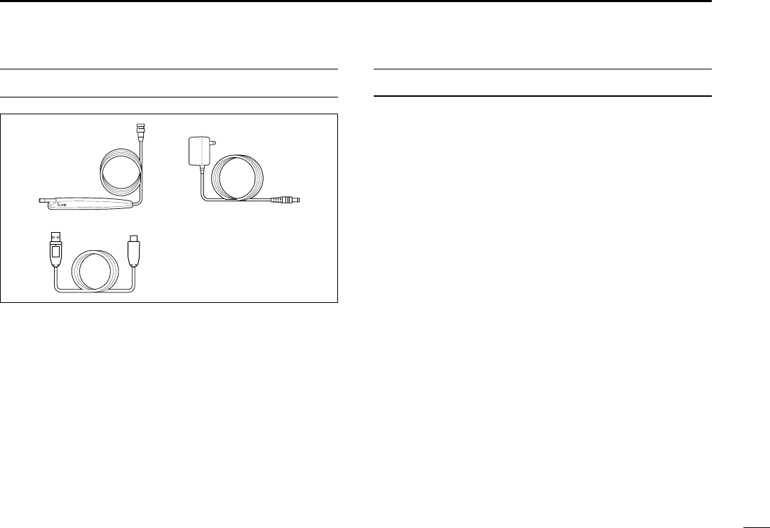
SUPPLIED ACCESSORIES
qAntenna …………………………………………………… 1
wAC adapter ………………………………………………… 1
eUSB cable ………………………………………………… 1
rCD ………………………………………………………… 1
tLeg pad …………………………………………………… 1
SYSTEM REQUIREMENTS
PC
• Microsoft®Windows®98SE/Me/2000/XP is installed
• With USB port
qw
e
IBM is registered trademark of International Business Machines Corporation in
the U.S.A. and other countries. Microsoft®and Windows®are registered trade-
marks of Microsoft Corporation in the U.S.A and other countries. Screen shots
produced with permission from Microsoft Corporation. All other products or
brands are registered trademarks or trademarks of their respective holders.
!IC-PCR1500.qxd 05.10.25 10:01 AM Page ii (1,1)

iii
New2001
RWARNING RF EXPOSURE! This device emits Radio
Frequency (RF) energy. Extreme caution should be observed when
operating this device. If you have any questions regarding RF expo-
sure and safety standards please refer to the Federal Communica-
tions Commission Office of Engineering and Technology’s report on
Evaluating Compliance with FCC Guidelines for Human Radio fre-
quency Electromagnetic Fields (OET Bulletin 65).
RWARNING! NEVER connect the receiver to an AC outlet.
This may pose a fire hazard or result in an electric shock.
RWARNING! NEVER operate the receiver while driving a
vehicle. Safe driving requires your full attention—anything less may
result in an accident.
NEVER connect the receiver to a power source of more than 16 V
DC. This will damage the receiver.
NEVER connect the receiver to a power source using reverse po-
larity. This will damage the receiver.
NEVER cut the DC power cable between the DC plug and fuse
holder. If an incorrect connection is made after cutting, the receiver
may be damaged.
NEVER expose the receiver to rain, snow or any liquids. The re-
ceiver may be damaged.
NEVER operate or touch the receiver with wet hands. This may
result in an electric shock or damage the receiver.
NEVER place the receiver where normal operation of the vehicle
may be hindered or where it could cause bodily injury.
NEVER let objects impede the operation of the cooling fan on the
rear panel.
AVOID using or placing the receiver in direct sunlight or in areas
with temperatures below –10°C (+14°F) or above +60°C (+140°F).
BE CAREFUL! The receiver will become hot when operating it
continuously for long periods.
AVOID setting the receiver in a place without adequate ventilation.
Heat dissipation may be affected, and the receiver may be damaged.
AVOID the use of chemical agents such as benzine or alcohol
when cleaning, as they can damage the receiver’s surfaces.
USE Icom microphones only (supplied or optional). Other manu-
facturer’s microphones have different pin assignments and may dam-
age the receiver if attached.
For U.S.A. only
CAUTION: Changes or modifications to this device, not ex-
pressly approved by Icom Inc., could void your authority to
operate this device under FCC regulations.
PRECAUTION
!IC-PCR1500.qxd 05.10.25 10:01 AM Page iii (1,1)

iv
New2001
FOREWORD ………………………………… i
IMPORTANT ………………………………… i
EXPLICIT DEFINITIONS …………………… i
PRECAUTION ……………………………… ii
SUPPLIED ACCESSORIES ……………… iii
TABLE OF CONTENTS …………………… iii
QUICK REFERENCE GUIDE …………… I–X
■Installation ……………………………… I
■Your first contact …………………… VII
■Repeater operation ………………… IX
■Programming memory channels ……X
1 PANEL DESCRIPTION ……………… 1–5
■Front panel— controller ……………… 1
■Function display ……………………… 3
■Rear panel …………………………… 5
2 SETTING A FREQUENCY ………… 6–8
■Turning power ON/OFF ……………… 6
■Mode selection ………………………… 6
■Tuning step selection ………………… 7
■Setting a frequency …………………… 7
■Receive mode selection ……………… 8
■Lock function 8
3 BASIC OPERATION ……………… 9–11
■Receiving ……………………………… 9
■Monitor function ……………………… 9
■Squelch attenuator ………………… 10
■AFC function ………………………… 10
■NB function …………………………… 11
■AGC function ………………………… 11
■VSC function ………………………… 11
TABLE OF CONTENTS
!IC-PCR1500.qxd 05.10.25 10:01 AM Page iv (1,1)
1
INSTALLATION
New2001
1
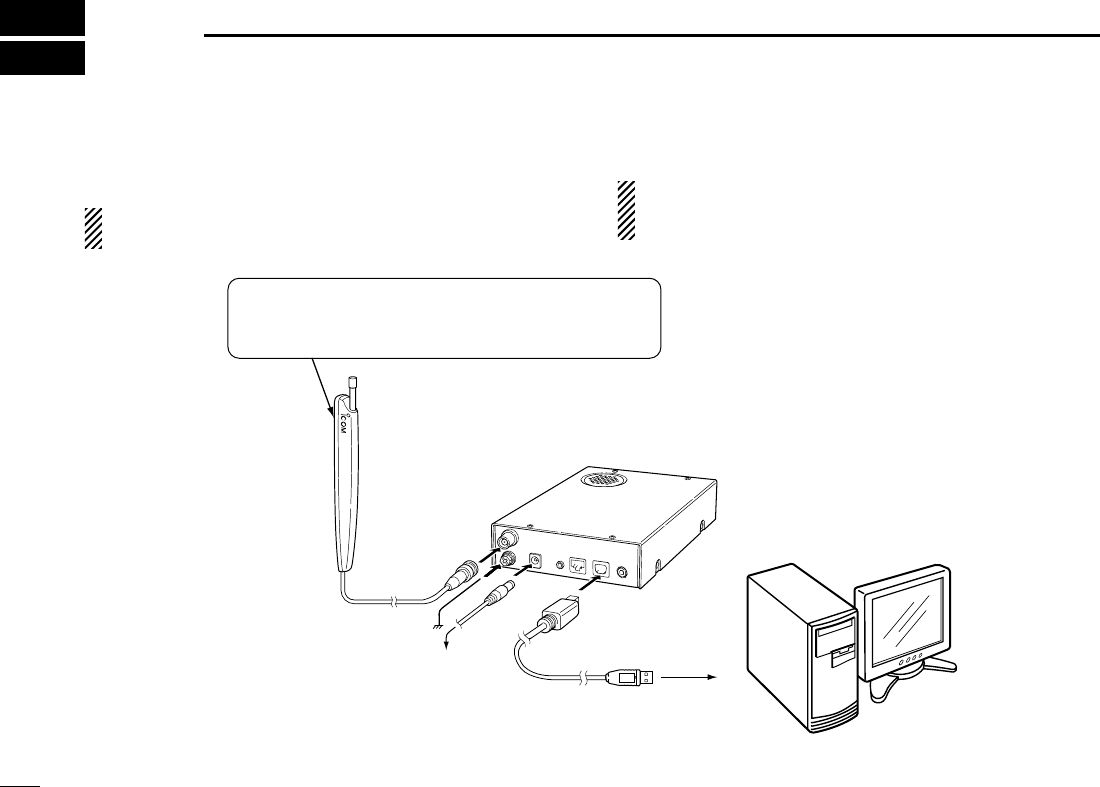
■Hardware installation
Refer to the diagram below for connections.
See p. ?? when you install the antenna other than the sup-
plied one.
CAUTION: We do not guarantee the receiver’s correct op-
eration if you use an USB cable that has been extended
or a cable other than the supplied one.
Receiver
To ground
Supplied antenna
PC
To AC adapter
to USB port
OPC-???
The double sided tape is set to the antenna holder.
Remove the protective paper when the antenna is
fixed to any place.
!IC-PCR1500.qxd 05.10.25 10:01 AM Page 1 (1,1)
2
1
INSTALLATION
New2001
1
2
3
4
5
6
7
8
9
10
11
12
13
14
15
16
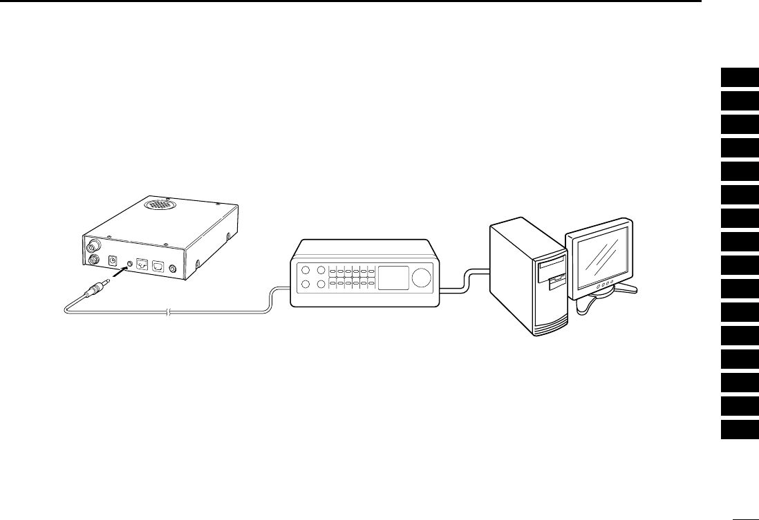
■TNC connection
Refer to the diagram below for connections.
The IC-PCR1500 can receive 9600 bps packet communica-
tion (AFSK). Connect the TNC (Terminal Node Controller) as
follows.
TNC
IC-PCR1500
PC
!IC-PCR1500.qxd 05.10.25 10:01 AM Page 2 (1,1)

5
1INSTALLATION
New2001
■Mouse property setting
The IC-PCR1500 uses left and right buttons to rotate a con-
trol knob on the multi-function receiver screen or to call up the
shortcut menu from the simple function receiver screen. De-
pending on the mouse property setting of the control panel,
main and sub mouse button functions are alternated.
In this instruction manual, the operation is described with
setting for right-handed (Windows®default setting).
DSetting the button configuration
qSelect ‘Settings’ from the [Start] menu and click ‘Control
Panel.’
wOpen the mouse control panel.
eSelect the button configuration to right- or left-handed.
rClick [OK] to set and exit the control panel.
!IC-PCR1500.qxd 05.10.25 10:01 AM Page 5 (1,1)

6
2
DRIVER INSTALLATION
1
2
3
4
5
6
7
8
9
10
11
12
13
14
15
16
The displayed dialog boxes or indications may differ
slightly from the following instructions according to your
system conditions, or environment.
■Microsoft®Windows®XP
qConnect the IC-PCR1500 to the desired USB port.
• Push [POWER] to turn the power ON.
• “Found New Hardware” appears as below.
wThe “Found New Hardware Wizard” will come up as below.
Insert the supplied CD into the CD drive, select “Install the
software automatically (Recommended),” then click
[Next>].
!IC-PCR1500.qxd 05.10.25 10:01 AM Page 6 (1,1)

7
2DRIVER INSTALLATION
New2001
eThe wizard starts searching for the driver and shows the
dialog below during search.
rAfter the driver is found, the “Hardware Installation” dialog
box appears as below.
Click [Continue Anyway] to start the installation.
tWindows starts installing the USB driver.
yAfter the installation is completed, click [Finish].
!IC-PCR1500.qxd 05.10.25 10:01 AM Page 7 (1,1)

8
2
DRIVER INSTALLATION
New2001
1
2
3
4
5
6
7
8
9
10
11
12
13
14
15
16
uThe “Found New Hardware Wizard” will come up again to
install the USB serial port driver.
Select “Install the software automatically (Recommended),”
then click [Next>].
iAfter the driver is found, the “Hardware Installation” dialog
box appears as below.
Click [Continue Anyway] to start the installation.
oWindows starts installing the USB driver.
!IC-PCR1500.qxd 05.10.25 10:01 AM Page 8 (1,1)

9
2DRIVER INSTALLATION
New2001
!0After the installation is completed, click [Finish].
!1After clicking [Finish], the dialog appears as below.
!2Eject the CD.
• Rebooting the PC is recommended.
■Microsoft®Windows®98SE/ Me
qConnect the IC-PCR1500 to the desired USB port.
• Push [POWER] to turn the power ON.
• “New Hardware is found” dialog box appears.
wThe “New Hardware Found” will come up as below. Click
[Browse...].
eInsert the supplied CD into the drive.
rClick [Z] to select the appropriate CD-ROM drive then click
“Driver” folder. After the driver is found, click [OK].
!IC-PCR1500.qxd 05.10.25 10:01 AM Page 9 (1,1)

10
2
DRIVER INSTALLATION
New2001
1
2
3
4
5
6
7
8
9
10
11
12
13
14
15
16
tClick [OK].
• The driver installation starts.
yAfter the installation, eject the CD.
• Rebooting the PC is recommended.
■Microsoft®Windows®2000
qConnect the IC-PCR1500 to the desired USB port.
• Push [POWER] to turn the power ON.
• “Found New Hardware” dialog box appears below.
wThe “Found New Hardware Wizard” will come up as below.
Click [Next>].
!IC-PCR1500.qxd 05.10.25 10:01 AM Page 10 (1,1)

11
2DRIVER INSTALLATION
New2001
eSelect “Search for a suitable driver for my device (recom-
mended),” then click [Next>].
rSelect “CD-ROM drives,” and insert the supplied CD into
the CD drive, then click [Next>].
!IC-PCR1500.qxd 05.10.25 10:01 AM Page 11 (1,1)

12
2
DRIVER INSTALLATION
New2001
1
2
3
4
5
6
7
8
9
10
11
12
13
14
15
16
tWhen the driver is found, the following dialog is displayed.
Click [Next>] to start the installation.
NOTE: When the appropriate driver is not found, a differ-
ent dialog is displayed. In such case, click [<Back], select
“Specify a location,” click [Next>], then type “D:\driver” in
the text box to select the “Driver” folder in the CD (if CD
drive is D).
yAfter the installation is completed, click [Finish].
uThe “Found New Hardware” wizard appears again.
!IC-PCR1500.qxd 05.10.25 10:01 AM Page 12 (1,1)

13
2DRIVER INSTALLATION
New2001
iClick [Next>]. oSelect “Search for a suitable driver for my device (recom-
mended),” then click [Next>].
!IC-PCR1500.qxd 05.10.25 10:01 AM Page 13 (1,1)

14
2
DRIVER INSTALLATION
New2001
1
2
3
4
5
6
7
8
9
10
11
12
13
14
15
16
!0Select “CD-ROM drives,” then click [Next>]. !1When the driver is found, the following dialog is displayed.
Click [Next>] to start the installation.
NOTE: When the appropriate driver is not found, a differ-
ent dialog is displayed. In such case, click [<Back], select
“Specify a location,” click [Next>], then type “D:\driver” in
the text box to select the “Driver” folder in the CD (if CD
drive is D).
!IC-PCR1500.qxd 05.10.25 10:01 AM Page 14 (1,1)

15
2DRIVER INSTALLATION
New2001
!2After the installation is completed, click [Finish].
!3Eject the CD.
• Rebooting the PC is recommended.
■COM port confirmation
After the driver installation, confirm the driver availability and
the port number are recommended.
In this section, screen shots of Windows XP are used for in-
struction example. However, the instructions are similar to an-
other operating systems, Windows 98SE, Me and 2000.
qBoot up the Windows.
wSelect the “Control Panel” in the Start menu.
• Control panel appears as shown in the next step below.
eClick the “Performance and Maintenance.”
• Performance and Maintenance menu appears.
rClick the “System,” then click the “Hardware” tab in the dis-
played System Properties screen.
!IC-PCR1500.qxd 05.10.25 10:01 AM Page 15 (1,1)

16
2
DRIVER INSTALLATION
New2001
1
2
3
4
5
6
7
8
9
10
11
12
13
14
15
16
tClick the [Device Manager].
• Device Manager screen appears as below.
yClick “ ” of the “Ports (COM & LPT)” to display the usable
COM port and the port number.
uConfirm the USB serial port availability and the COM port
number.
• The COM port number is used for the COM port setup. (p. ??)
iClose the Device Manager, System Properties screen and
then Control panel.
!IC-PCR1500.qxd 05.10.25 10:01 AM Page 16 (1,1)

17
APPLICATION INSTALLATION
New2001
3
qInsert the CD into the CD drive.
wOpen the CD drive contents via “My computer” or “Win-
dows Explorer.”
• “Driver” and “ICPCR1500” folders are available.
eDouble click “Setup.exe” file in “IC-PCR1500” folder.
• The “InstallShield®Wizard” starts preparing the installation.
rAfter the preparation, the following dialog is displayed.
Click [Next>].
!IC-PCR1500.qxd 05.10.25 10:01 AM Page 17 (1,1)

18
3
APPLICATION INSTALLATION
New2001
1
2
3
4
5
6
7
8
9
10
11
12
13
14
15
16
tConfirm the location, then click [Next>] to start the installa-
tion.
• Click [Browse...] then type the desired location if you specifying
the installation location.
yAfter the installation is completed, click [Finish].
uEject the CD.
• The IC-PCR1500 shortcut icon is created on the desktop.
• Rebooting the PC is recommended.
!IC-PCR1500.qxd 05.10.25 10:01 AM Page 18 (1,1)
19
PANEL DESCRIPTION
New2001
4
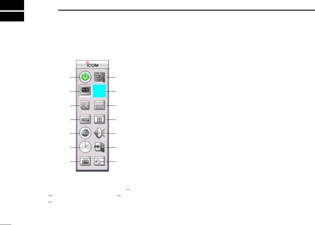
qCOMPONENT BUTTON (p. ??)
Click to toggle the Tuning panel screen (T), Mode panel
screen (M), Meter/Scan panel screen (E) and Scope panel
screen (S) appear/ disappear.
wCOMPACT BUTTON (p. ??)
Click to display the compact screen.
eDTMF REMOTE COMMANDER BUTTON (p. ??)
Click to toggle the DTMF remote commander screen ap-
pear/disappear.
rMULTI CHANNEL MONITOR BUTTON (p. ??)
Click to toggle the multi channel monitor screen appear/dis-
appear.
tAUDIO SETTING BUTTON (p. ??)
Click to toggle the audio setting screen appear/disappear.
yEXIT BUTTON
Click to quit the IC-PCR1500 program.
uUSB PORT SETTING BUTTON (p. ??)
Click to toggle the USB setting screen appear/disappear.
iAUTO MODE SETTING/
SHORT CUT KEY SETTING BUTTON (p. ??)
Click to toggle the auto mode setting list and short cut key
list screen appear/disappear.
oTIMER SETTING BUTTON (p. ??)
Click to toggle the auto power OFF function is turned ON.
!0RECORDING BUTTON (p. ??)
Click to record the receiving signal.
!1DSP DIGITAL FILTER BUTTON (p. ??)
Click to toggle the DSP digital filter screen appear/disap-
pear.
!0
o
i
!1
!2
!3
!4 q
w
e
r
t
y
u
■Tool bar
The application screen can be seen after the application installation. See page ?? for details.
!IC-PCR1500.qxd 05.10.25 10:01 AM Page 19 (1,1)

20
4
PANEL DESCRIPTION
New2001
1
2
3
4
5
6
7
8
9
10
11
12
13
14
15
16
!2MEMORY CHANNEL BUTTON (p. ??)
Click to toggle the memory channel screen appear/disap-
pear.
!3COMMUNICATION RECEIVER BUTTON (p. ??)
Click to display the communication receiver screen.
!4POWER BUTTON (p. ??)
Click to turn the PCR-1500 interface unit receive circuit and
program ON or OFF.
!IC-PCR1500.qxd 05.10.25 10:01 AM Page 20 (1,1)
21
4PANEL DESCRIPTION
New2001
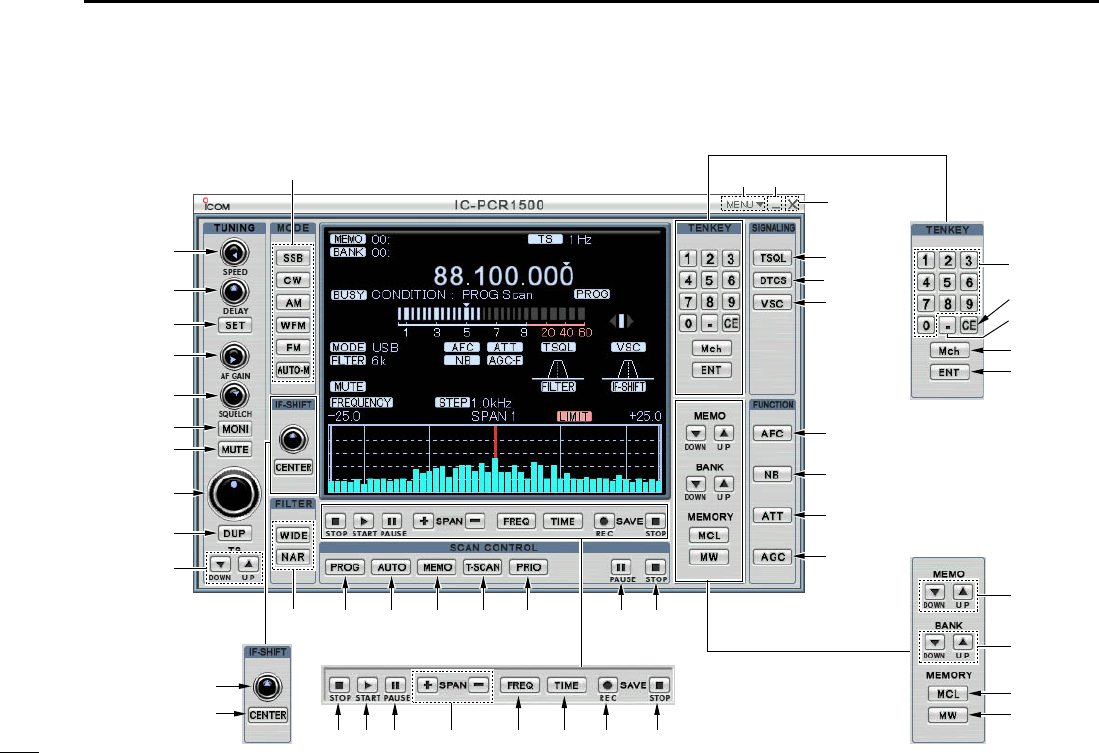
■Multi-function receiver screen
!5
!6
!4
@1
@9@8@7 #1 #2
#6
#5
$4
$5
q
#4
#3
@6@5 #0
@2
!7
$8
rwe
$7
$6
y
u
i
o
t
!0
!1
!2
!3
!8 !9 @0 @3 @4
#7
#8
#9
$0
$1
$2
$3
!IC-PCR1500.qxd 05.10.25 10:01 AM Page 21 (1,1)

22
4
PANEL DESCRIPTION
New2001
1
2
3
4
5
6
7
8
9
10
11
12
13
14
15
16
qCLOSE BUTTON
Click to quit and exit the application screen.
wMINIMIZE BUTTON
Click to minimize the application screen.
eMENU LIST
Click to display the menu list to perform the following oper-
ation.
• Turning the receiver power ON/OFF
• Creating a new file
• Opening a file
• Saving (over-write or with different file name) the set con-
tents.
• Quitting the application
rRECEIVE MODE BUTTONS [SSB], [CW], [AM], [WFM],
[FM], [AUTO-M] (pgs. ??, ??)
Click to select a receive mode.
• When using [AUTO-M] (automatic mode), a receive mode, IF
filter passband width, tuning step, etc., are selected automatically
after inputting a frequency. (p. ??)
tSCAN SPEED CONTROL [SPEED] (p. ??)
Click to set the speed at which scans search through fre-
quencies/memories for signals.
• Right-click to increase the speed level.
• Left-click to decrease the speed level.
ySCAN DELAY TIME CONTROL [DELAY] (p. ??)
Click to set the period in which a scan pauses after receiv-
ing a signal.
• Right-click to increase the period.
• Left-click to decrease the period.
uSET BUTTON [SET]
Click to show the [Scan Delay] screen.
This screen is used for the settings of the scan function,
band scope function, the automatic mode select function,
etc.
iAUDIO FREQUENCY GAIN CONTROL [AF GAIN]
Click to adjust the audio output level.
• Right-click to increase the audio output level.
• Left-click to decrease the audio output level.
oSQUELCH CONTROL [SQUELCH] (p. ??)
Click to adjust the squelch threshold level.
The squelch removes noise output from the speaker
(closed condition) when no signal is received.
• Right-click to close the squelch.
• Left-click to open the squelch.
!0MONITOR BUTTON [MONI] (p. ??)
Click to turn the monitor function ON or OFF.
The monitor function is used to temporarily open the
squelch to listen to weak signal.
!1MUTE BUTTON [MUTE] (p. ??)
Click to turn the mute function ON or OFF.
This function is used to temporarily mute audio output.
!IC-PCR1500.qxd 05.10.25 10:01 AM Page 22 (1,1)

23
4PANEL DESCRIPTION
New2001
■Multi-function receiver screen (Continued)
!2TUNING DIAL (p. ??)
Click to set the receive frequency with the selected tuning
step.
• Right-click to increase the frequency.
• Left-click to decrease the frequency.
!3DUPLEX BUTTON [DUP] (p. ??)
➥Right-click to display the offset frequency setting screen.
➥Left-click to set the duplex direction from OFF (no
indication), DUP –, and DUP +.
!4TUNING STEP UP/DOWN BUTTONS [Y]/[Z](p. ??)
➥Right-click to display the tuning step setting screen.
➥Left-click to select the tuning steps in order.
!5IF-SHIFT CONTROL (p. ??)
Click to set a signal passband position.
• Right-click to increase the signal passband position.
• Left-click to decrease the signal passband position.
!6CENTER KEY [CENTER] (p. ??)
After moving a signal passband position with clicking the
IF-shift control, click to return to the center position.
!7IF FILTER BUTTONS [WIDE]/[NAR] (p. ??)
Click to change the IF filter in use.
• Click [WIDE] to select a wide filter.
• Click [NAR] to select a narrow filter.
*Usable IF filter is according to the receive mode.
!8PROGRAMMED SCAN BUTTON [PROG] (p. ??)
Click to start/stop a programmed scan.
• “PROG Scan” blinks during scanning.
!9AUTO MEMORY WRITE SCAN BUTTON [AUTO] (p. ??)
Click to start/stop an auto memory write scan.
• “AUTO Scan” blinks during scanning.
@0MEMORY SCAN BUTTON [MEMO] (p. ??)
Click to start/stop a memory scan.
• “MEMO Scan” blinks during scanning.
@1TONE SCAN BUTTON [T-SCAN] (p. ??)
Click to start/stop a tone scan.
• “TONE Scan” blinks during scanning.
@2PRIORITY SCAN BUTTON [PRIO] (p. ??)
Click to start/stop a priority scan.
• “PRIO Scan” blinks during scanning.
@3WEATHER ALERT BUTTON [WX] (p. ??)
Push to start the weather alert function.
@3SCAN PAUSE BUTTON [PAUSE] (p. ??)
Push to pause/resume a scan.
• “Pause” blinks during scan is pausing.
@4SCAN STOP BUTTON [STOP] (p. ??)
Push to cancel a scan operation.
@5SWEEP STOP BUTTON [■](p. ??)
Click to stop a band scope function.
@6SWEEP START BUTTON [≈≈](p. ??)
Click to start the band scope function which is used to
observe signal conditions around the receive frequency.
!IC-PCR1500.qxd 05.10.25 10:01 AM Page 23 (1,1)

24
4
PANEL DESCRIPTION
New2001
1
2
3
4
5
6
7
8
9
10
11
12
13
14
15
16
@7SWEEP PAUSE BUTTON [❙❙](p. ??)
Click to pause/resume a band scope sweeping.
NOTE: While using the band scope function, audio is
not output. To monitor the frequency, push [❙❙] to pause
the function, or push [■] to cancel the function.
@8SPAN (TIME) UP/DOWN BUTTON [Y]/[Z](p. ??)
When “FREQUENCY” table is displayed;
Click to select the band scope edge frequency.
When “TIME” table is displayed;
Click to select the time interval to show the receiving
signal.
@9FREQUENCY BUTTON [FREQ]
Click to show the receiving signal relative to signal
strength.
#0TIME BUTTON [TIME]
Click to show the receiving signal condition on that time.
#1REC BUTTON
Click to start recording of the receiving signal contents.
#2STOP BUTTON
Click to stop recording.
#3MEMORY WRITE BUTTON [MW] (p. ??)
Click to write the current receive frequency into the
selected memory channel.
#4MEMORY CLEAR BUTTON [MCL] (p. ??)
Click to clear the unneeded (displayed??) memory channel
contents.
#5BANK UP/DOWN BUTTONS [Y]/[Z](p. ??)
Click to change the memory bank.
#6MEMORY CHANNEL UP/DOWN BUTTONS [Y]/[Z]
(p. ??)
Click to change a memory channel.
#7AUTOMATIC GAIN CONTROL BUTTON [AGC] (p. ??)
Click to turn the AGC (Automatic Gain Control) function ON
or OFF.
• “AGC” appears when the AGC function is turned ON.
#8ATTENUATOR BUTTON [ATT] (p. ??)
Click to turn the ATT (Attenuator) function ON or OFF.
• “ATT” appears when the ATT function is turned ON.
#9NOISE BLANKER BUTTON [NB] (p. ??)
Click to turn the NB (Noise Blanker) function ON or OFF.
• “NB” appears when the NB function is turned ON.
$0AUTOMATIC FREQUENCY CONTROL BUTTON [AFC]
(p. ??)
Click to turn the AFC (Automatic Frequency Control)
function ON or OFF.
• “AFC” appears when the AFC function is turned ON.
!IC-PCR1500.qxd 05.10.25 10:01 AM Page 24 (1,1)

25
4PANEL DESCRIPTION
New2001
■Multi-function receiver screen (Continued)
$1VOICE SCAN CONTROL BUTTON [VSC] (p. ??)
Click to turn the VSC (Voice Scan Control) function ON or
OFF.
• “VSC” appears when the VSC function is turned ON.
$2DTCS SETTING BUTTON [DTCS] (p. ??)
➥Click to display the DTCS code setting screen, then click
[Z]to select the desired code.
➥Click the polarity radio button to select the polarity from
Normal or Reverse.
• Available only when FM mode is selected.
• “DTCS” appears when the DTCS code and polarity are set.
• Click again to cancel the DTCS setting.
$3CTCSS SETTING BUTTON [TSQL] (p. ??)
Click to display the tone squelch frequency setting screen,
then click [Z]to select the desired frequency.
• Available only when FM mode is selected.
• “CTCSS” appears when the tone squelch frequency is set.
• Click again to cancel the CTCSS setting.
$4ENTER KEY [ENT]
Click to enter the frequency when the desired receive
frequency is input via the 10 keypad.
$5MEMORY CHANNEL KEY [Mch]
Click to call the memory channel when the desired channel
number is input via the 10 keypad.
$6TENKEY— DECIMAL BUTTON [.]
Click to set the MHz digit when inputting a frequency via
the 10 keypad.
$7TENKEY— CLEAR BUTTON [CE]
Click to clear the mistake while inputting a receive
frequency or memory channel number via the 10 keypad.
$8TENKEY— NUMERAL BUTTONS [1] to [0]
The numeral buttons can be used for several functions as
below:
• Direct receive frequency input.
• Memory channel input.
!IC-PCR1500.qxd 05.10.25 10:01 AM Page 25 (1,1)
26
4
PANEL DESCRIPTION
New2001
1
2
3
4
5
6
7
8
9
10
11
12
13
14
15
16
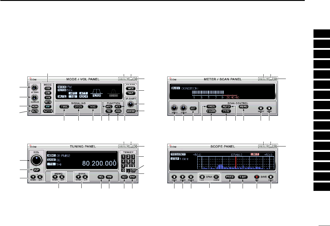
■Component screen
The setting items of a component screen are same with a
multi-function receiver screen’s one. Please refer to the ex-
planations on pgs ?? to ??
#6
q
w
e
q
w
e
w
e
q
w
e
r
i
o
!0
!1
$1 #7 #8#9$0
!5
!6
!7
!2
!3
!4
#65 #4
tyu @0@1 @2 @3 @4!8 !9
@8@5 @7@6 @9 #1 #2#0
q
$7
$6
$8
$5 $4#3
$3 $2
!IC-PCR1500.qxd 05.10.25 10:01 AM Page 26 (1,1)
27
4PANEL DESCRIPTION
New2001
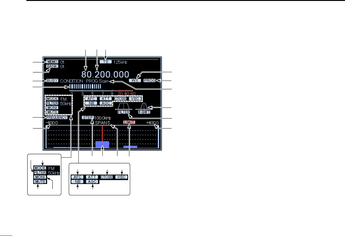
qFREQUENCY READOUT (p. ??)
Indicates the receive frequency and data as it is being
input such as memory channel numbers, etc.
w?? INDICATOR (p. ??)
Indicates the tuning digit.
eTUNING STEP INDICATOR (p. ??)
This is the frequency increment used when selecting a fre-
quency using the tuning dial and when searching for sig-
nals using a scan function.
rWEATHER INDICATOR (p. ??)
Appears when weather function is turned ON. (USA ver-
sion only)
tSCAN INDICATOR (p. ??)
“PROG,” “AUTO,” “MEMO,” “T-SCAN” or “PRIO” appears
during scanning.
yCONDITION INDICATOR (p. ??)
“PROG Scan,” “AUTO Scan,” “MEMO Scan,” “TONE
Scan” or “PRIO Scan” blinks during scanning.
uIF-SHIFT INDICATOR
Indicates the received signal passband position.
iIF-FILTER PASSBAND WIDTH INDICATOR
Indicates the current signal passband width.
oMAXIMUM FREQUENCY SPAN INDICATORS (p. ??)
➥Indicate the upper and lower observable frequency lim-
its around a receive frequency.
➥In the diagram, the upper and lower limits are ±500
kHz.
!0 LIMIT INDICATOR (p. ??)
Appears when the tuning step (e) is larger than the auto-
matic sweep step (!3) setting.
• The limit indicator is not indicated when the tuning step and the
sweep step width are the same.
w
!2
@7
@5
@3
@4
@6
i
!0!1!3
i
o
t
u
q e
r
y
!4 !7!6!5
!9 !8
@0
@1 @2
!9
■Function display (for Multi-function receiver screen)
!IC-PCR1500.qxd 05.10.25 10:01 AM Page 27 (1,1)

28
4
PANEL DESCRIPTION
New2001
1
2
3
4
5
6
7
8
9
10
11
12
13
14
15
16
!1 FREQUENCY SPAN INDICATOR (p. ??)
Indicates the frequency span selected with the [SPAN Y]
or [SPAN Z] button.
!2 CENTER FREQUENCY INDICATOR (p. ??)
Indicates the center frequency of the frequency span; this
is for the currently received frequency.
!3 SWEEP STEP INDICATOR (p. ??)
Indicates band scope sweep step.
!4AFC INDICATOR [AFC] (p. ??)
Appears when the AFC (Automatic Frequency Control)
function is ON.
!5 ATTENUATOR INDICATOR [ATT] (p. ??)
Appears when the ATT (Attenuator) function is ON.
!6CTCSS/DTCS INDICATOR [CTCSS]/[DTCS] (p. ??)
➥“CTCSS” appears when the tone squelch frequency is set.
➥“DTCS” appears when DTCS code and the polarity are set.
!7VSC INDICATOR [VSC] (p. ??)
Appears when the VSC (Voice Scan Control) function is ON.
!8NB INDICATOR [NB] (p. ??)
Appears when the NB (Noise Blanker) function is ON.
!9AGC INDICATOR [AGC] (p. ??)
Appears when the AGC (Automatic Gain Control) function
is ON.
@1 IF FILTER INDICATOR (p. ??)
Indicates the selected IF filter.
@2 RECEIVE MODE INDICATORS (p. ??)
Indicate the current receive mode.
• “WFM” lights in red when receiving a stereo broadcast program.
@1 MUTE INDICATOR (p. ??)
Appears when the squelch circuit mute the received audio
signal.
@1 MONI INDICATOR (p. ??)
Appears during monitoring the operating frequency.
@0 FREQUENCY/TIME INDICATOR [FREQUENCY]/[TIME]
(p. ??)
➥“FREQUENCY” appears when the receiving signal
relative to signal strength is displayed.
➥“TIME” appears when the receiving signal condition on
that time is displayed.
@3 S (SIGNAL) METER (pgs. ??, ??)
Indicates the receive signal strength. Also indicates the
S-meter squelch receive level set via the [SQUELCH] con-
trol.
@4 BUSY INDICATOR [BUSY]
Appears when receiving a signal or when signal noise
opens the squelch.
@5 MEMORY BANK INDICATOR (p. ??)
Indicates the memory bank number (and name if it is set)
being received.
@6 MEMORY CHANNEL INDICATOR (p. ??)
Indicates the memory channel number (and name if it is
set) being received.
• The name darkens when the receive frequency changes from
the stored one.
!IC-PCR1500.qxd 05.10.25 10:01 AM Page 28 (1,1)
29
4PANEL DESCRIPTION
New2001
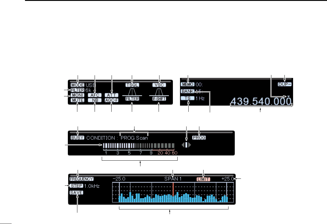
■Function display (for Component screen)
The setting items of a component screen are same with a
multi-function receiver screen’s one. Please refer to the ex-
planations on pgs ?? to ??
@5
@4
@7
!5
@3
!0
@1 @0 o
@6
i r
#0 e!6 !7 !8 !9@6
@8
@2 !2!3
y tu
@9
!4
q
w
!1
!IC-PCR1500.qxd 05.10.25 10:01 AM Page 29 (1,1)
30
4
PANEL DESCRIPTION
New2001
1
2
3
4
5
6
7
8
9
10
11
12
13
14
15
16
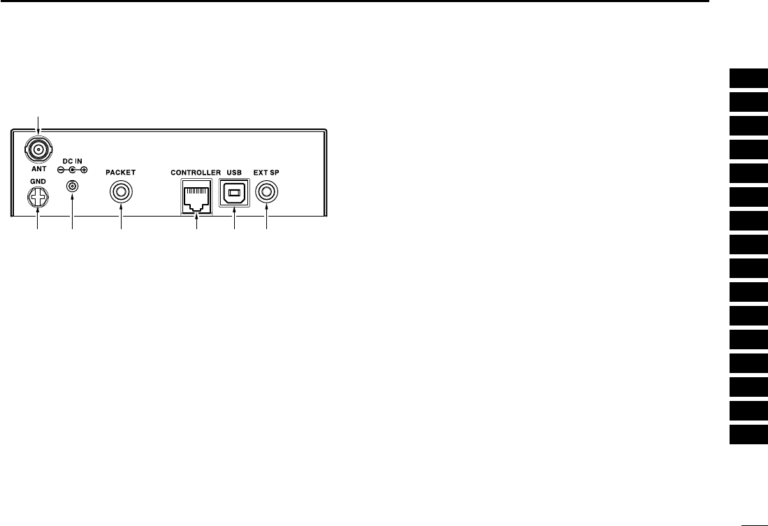
■Rear Panel
qANTENNA CONNECTOR [ANT]
Connects a 50 Ωantenna with a BNC connector and a 50
Ωcoaxial cable.
wEXTERNAL SPEAKER JACK [EXT SP]
Connects an 8 Ωexternal speaker.
• Audio output power is more than 0.5 W.
eUSB RECEPTACLE [USB]
Connects to a PC via an extension cable.
rCONTROLLER [CONTROLLER]
Connects to a controller via an extension cable.
tDATA SOCKET [PACKET]
Connects a TNC (Terminal Node Controller), etc. for data
communications. The receiver can receive 9600 bps
packet communication (AFSK.)
• See p. ? for connection information.
yPOWER RECEPTACLE [DC IN]
Accepts 12 V DC ±15% with the supplied DC power cable.
☞NOTE: DO NOT use a cigarette lighter socket as a
power source when operating in a vehicle. The plug
may cause voltage drops and ignition noise may be su-
perimposed onto receive audio.
uGROUND TERMINAL [GND]
Connect this terminal to a ground.
q
uy t r ew
!IC-PCR1500.qxd 05.10.25 10:01 AM Page 30 (1,1)

31
BASIC OPERATION
New2001New2001
5
■Launching the IC-PCR1500
qBefore launching the IC-PCR1500 program, make sure the
receiver’s power ON. Then launch the IC-PCR1500 pro-
gram. (p. ??)
wClick “ ” on the tool bar to turn the IC-PCR1500 ON.
eClick the desired icon (multi-function receiver, component
or simple) on the tool bar to select the receiver screen that
you want to use.
■Changing the receiver screen
Click the desired tool bar icon that you want to use.
• Click [Receiver] for the multi-function receiver screen.
• Click [Comp] for the component screen.
• Click [Simple] for the simple screen.
!IC-PCR1500.qxd 05.10.25 10:01 AM Page 31 (1,1)

32
5
BASIC OPERATION
1
2
3
4
5
6
7
8
9
10
11
12
13
14
15
16
New2001
■Closing the IC-PCR1500
DUsing the multi-function receiver screen or
component screen
Click [Close] in the menu list, or close button ([X]) to quit the
IC-PCR1500 program.
• Click [Close] in the menu list, or close button (X) in each [TUNING
PANEL], [MODE/VOL PANEL], [METER/SCAN PANEL] and
[SCOPE PANEL] when the component screen is displayed.
DSimple screen
Click
■Quitting the IC-PCR1500
DUsing the multi-function receiver screen or
component screen
Click “ ” on the tool bar or [Power OFF] in the menu list to
quit the IC-PCR1500.
DSimple screen
Click
!IC-PCR1500.qxd 05.10.25 10:01 AM Page 32 (1,1)

33
5BASIC OPERATION
New2001
■Receiving
Make sure the hardware installation is finished. (p. ??)
DUsing the multi-function receiver screen or
component screen
qClick “ ” to turn power ON.
wClick [AF GAIN] to set the audio level.
• Right-click to increase the audio level.
• Left-click to decrease the audio level.
• When clicking and holding [AF GAIN], the audio level scrolls up
or down.
• Push the PC‘s [↑] (UP) or [↓] (DOWN) key also sets the audio
level.
eClick [SQUELCH] to set the squelch level.
• Right-click to increase the squelch level (tight squelch).
• Left-click to decrease the squelch level (loose squelch).
• When clicking and holding [SQUELCH], the squelch level scrolls
up or down.
rSet the receive frequency and mode. (pgs. ??, ??)
tWhen receiving a signal on the set frequency, squelch
opens and the receiver emits audio.
• “BUSY” appears and the S-meter indicator shows the relative
signal strength for the received signal.
■Setting a frequency
Depending on the situation, the receive frequency can be set
using the following methods. Frequencies can be set from
0.01000 to 3299.00000 MHz.
DUsing the tuning dial
➥Click [DIAL] to set the receive frequency with the selected
tuning step.
• Right-click to increase the frequency.
• Left-click to decrease the frequency.
• The frequency changes according to the preset tuning steps. See
p. ?? for selecting the tuning step.
• When clicking and holding either button the frequency scrolls up
or down.
DUsing the 10-keypad
➥Click the desired numeral buttons, then click [ENT] to set
the frequency.
• When making a mistake while inputting a frequency, click [CE] to
clear the input and return to the previous frequency.
• When you want to change the 100 kHz digit and below, click [•]
first, then the numeral buttons and then [ENT].
• When you want to set the 100 kHz digit and below to 0, input the
MHz digits and then click [ENT].
• When inputting a frequency outside of the allowed receive fre-
quency range, the previously selected frequency is automatically
selected after clicking [ENT].
!IC-PCR1500.qxd 05.10.25 10:06 AM Page 33 (1,1)

34
5
BASIC OPERATION
New2001
1
2
3
4
5
6
7
8
9
10
11
12
13
14
15
16
DUsing the PC keyboard
➥Push the desired numeral keys on the PC keyboard, then
push [Enter] to set the frequency.
• When inputting from the keyboard, click anywhere in the receiver
screen first, then begin inputting from the keyboard.
• When making a mistake while inputting a frequency, click [CE]
on the receiver screen to clear the input and return to the previ-
ous frequency.
• When you want to change the 100 kHz digit and below, push [•]
first, then the numeral keys and then [Enter].
• When you want to set the 100 kHz digit and below to 0, input the
MHz digits and then push [Enter].
• When inputting a frequency outside of the allowed receive fre-
quency range, the previously selected frequency is automatically
selected after clicking [Enter].
■Squelch level setting
The squelch function sets a minimum receive signal level
below which no audio is emitted from the speaker. This con-
veniently prevents noise and static from being emitted when
receiving weak signals or no signals at all.
Further setting of squelch removes weak signals. The remove
level is displayed on the S-meter (S-meter squelch). The
squelch does not open if a signal below the set S-meter level
is received.
DUsing the multi-function receiver screen or
component screen
➥Click [SQUELCH] to set the squelch level.
• Right-click to increase the squelch level (tight squelch).
• Left-click to decrease the squelch level (loose squelch).
• When clicking and holding [SQUELCH], the audio level scrolls
up or down.
• The S-meter squelch level is displayed in the function display.
DUsing the simple function receiver screen
qClick [MENU] and select the ‘Function controller’ when it
is not displayed.
wClick [SQL J] or [SQL K] on the function controller to se-
lect the desired squelch level.
• The S-meter squelch level is displayed under the frequency in-
dication.
!IC-PCR1500.qxd 05.10.25 10:01 AM Page 34 (1,1)

35
5BASIC OPERATION
New2001
■Setting a tuning step
When using the tuning dial to change the frequency, or when
a scan function is activated, the frequency changes in incre-
ments determined by the set tuning step. This can be
changed if desired.
The following tuning step are available.
• 1 Hz • 10Hz • 20 Hz • 50 Hz • 100 Hz
• 500Hz • 1 kHz • 2.5 kHz • 5 kHz • 6.25 kHz
• 8.33 kHz • 9 kHz • 10 kHz • 12.5 kHz • 15 kHz
• 20 kHz • 25 kHz • 30 kHz • 50 kHz • 100 kHz
• 125 kHz • 150 kHz • 200 kHz • 500 kHz • 1 MHz
• 10 MHz • USER*
*When “USER” is selected, the tuning step, set in “USER TS Setting”
screen, is selected.
DTuning step selection
➥Right-click [TS YY]or [TS ZZ]to display a tuning step list,
then select the desired tuning step.
➥Left-click [TS YY]or [TS ZZ]to set the desired tuning step in
order.
• The selected tuning step is displayed in the function display.
DSetting the user tuning step
➥Right-click [TS YY]or [TS ZZ]to display a tuning step list,
then select “USER TS Setting.” You can edit the desired
tuning step from 0.001 kHz–9999.998 kHz (in 0.001 step)
directly.
■Receive mode selection
Receive modes are determined by the physical properties of
the radio signals. The receiver has 6 receive modes: SSB
LSB, CW, AM, WFM and FM modes. The mode selection is
stored independently in each memory channels.
Typically, AM mode is used for the AM broadcast stations
(0.495–1.620 MHz) and air band (118–135.995 MHz), and
WFM is used for FM broadcast stations (76–107.9 MHz).
When using [AUTO-M] (automatic mode), a receive mode, IF
filter passband width, tuning step, etc., are selected
automatically after inputting a frequency. (p. ??)
➥Click [SSB], [CW], [AM], [WFM], [FM] or [AUT-M] to select
the desired receive mode.
• Clicking [SSB] toggles the USB and LSB mode.
!IC-PCR1500.qxd 05.10.25 10:01 AM Page 35 (1,1)

36
5
BASIC OPERATION
New2001
1
2
3
4
5
6
7
8
9
10
11
12
13
14
15
16
■Automatic mode selection
An automatic mode function is available to automatically set
the receive mode, IF filter passband width, tuning step, etc.
after inputting a frequency.
Each click of the [AUTO-M] button toggles the automatic
mode function ON and OFF.
DSetting the automatic mode function
The default setting for the automatic mode function can be
added to, changed or deleted. Up to 20 ranges can be mem-
orized into the automatic mode function settings.
qClick “ ” on the tool bar to call up the [Setting] screen if it
is not displayed.
wClick the [Auto Mode] tab to display the automatic mode
list.
eClick a cell in the [Freq Low] column and the desired line.
rInput the lower frequency of the frequency range from the
keyboard, then push [Enter].
• When nothing is input into the [Freq Low] or [Freq High] column,
settings for other columns cannot be made.
• When inputting a new frequency, other data automatically ap-
pears in the other column.
• To delete a frequency range setting, enter [0] or [Space] into the
[Freq Low] column from the keyboard.
tInput the higher frequency of the frequency range into the
[Freq High] column, push the [Enter] key.
ySet other data such as mode, tuning step, etc., if desired.
• Double-click the desired cell, select the desired item and double-
click the selection.
uClick the close button ([X]) to close the setting screen.
!IC-PCR1500.qxd 05.10.25 10:01 AM Page 36 (1,1)

37
5BASIC OPERATION
New2001
■Monitor function
This function is used to listen to weak signals without disturb-
ing the squelch setting or to open the squelch manually even
when mute functions such as the tone squelch are in use.
➥Click [MONI] to monitor the operating frequency.
• “MONI” appears.
■Mute function
This function is used to mutes the received audio signal.
➥Click [MUTE] to temporarily mute audio output.
• “MUTE” appears.
!IC-PCR1500.qxd 05.10.25 10:01 AM Page 37 (1,1)

38
5
BASIC OPERATION
New2001
1
2
3
4
5
6
7
8
9
10
11
12
13
14
15
16
!IC-PCR1500.qxd 05.10.25 10:01 AM Page 38 (1,1)
39
OTHER FUNCTIONS
New2001New2001
6
■Duplex operation
Duplex communication uses 2 different frequencies for trans-
mitting and receiving. Generally, duplex is used in communi-
cation through a repeater, some utility communications, etc.
During duplex operation, the transmit station frequency is
shifted from the receive station frequency by the offset fre-
quency. Repeater information (offset frequency and shift di-
rection) can be programmed into memory channels. (p. ??)
qSet the receive frequency (repeater output frequency).
tRight-click [DUP] to display the offset frequency setting
screen.
ySet the desired offset frequency within 0.000000–
1000.000000 MHz range, then click [OK].
wLeft-click [DUP] to set the duplex direction from OFF (no
indication,) DUP–, or DUP+.
eClick [MONI] to monitor the transmit station frequency (re-
peater input frequency).
The displayed frequency shifts the offset frequency when
monitor function is in use.
■IF filter selection
Increasing or decreasing the width of incoming signals can
help eliminate interference. Available filters vary according to
the receive mode. See the table below.
K: Available; –: Not available
➥Click the [WIDE] or [NAR] buttons to toggle between filter
widths.
■Attenuator function
Strong signals (such as from broadcast stations, pocket beep-
ers, nearby amateur radio stations, etc.) can cause distortion
of receive signals. The attenuator function can reduce signal
strength of interfering signals by approx. 20 dB.
➥Click [ATT] to turn the ATT (Attenuator) function ON or
OFF.
• “ATT” appears when the ATT function is turned ON.
2.8 kHz 6 kHzIF filter 15 kHz 50 kHz
KAM K—KK
230 kHz
KUSB/LSB K———
—FM KKK —
KCW K———
—WFM — — KK
!IC-PCR1500.qxd 05.10.25 10:01 AM Page 39 (1,1)

40
6
OTHER FUNCTIONS
1
2
3
4
5
6
7
8
9
10
11
12
13
14
15
16
New2001
■AFC function
The AFC (Automatic Frequency Control) function tunes the
displayed frequency automatically when an off-center fre-
quency is received. It activates in FM/WFM modes only.
➥Click [AFC] to turn the AFC (Automatic Frequency Control)
function ON or OFF.
• “AFC” appears when the AFC function is turned ON
■NB function
The NB (noise blanker) function removes pulse-type noise
when USB, LSB, CW or AM mode is selected.
➥Click [NB] to turn the NB (noise blanker) function ON or OFF.
• “NB” appears when the NB function is turned ON.
■AGC function
The AGC (Automatic Gain Control) function controls receiver
gain to produce a constant audio output level even when the
received signal strength is varied by fading, etc.
➥Click [AGC] to turn the AGC (Automatic Gain Control) func-
tion ON or OFF.
• “AGC” appears when the AGC function is turned ON.
■VSC function
When the VSC (Voice Scan Control) function is ON, the re-
ceived signals while scanning or when selecting a station and
which open the squelch but are not modulated (contain no
voice or music, etc. components) are muted. The BUSY indi-
cator still lights even no audio is emitted.
➥Click [VSC] to turn the VSC (Voice Scan Control) function
ON or OFF.
• “VSC” appears when the AFC function is turned ON.
■IF shift function
The IF shift function electronically changes the center of the
IF (intermediate frequency) passband frequency to reject in-
terference. It activates in SSB/CW modes only.
qAdjust the [SHIFT] control for a minimum interference sig-
nal level.
• The audio tone may be changed while the IF shift is in use.
wSet the shift control to its center position when there is no
interference.
!IC-PCR1500.qxd 05.10.25 10:01 AM Page 40 (1,1)

41
MEMORY CHANNELS
New2001New2001
7
■General
The receiver has 2600 memory channels for storage of often-
used frequencies. Total of 26 memory banks are available for
usage by group, etc., and 100 channels are assigned into a
bank.
DMemory channel contents
The following information can be programmed into memory
channels:
• Memory channel name
• Operating frequency (p. ??)
• Duplex direction (p. ??)
• Offset frequency (p. ??)
• Receive mode (p. ??)
• IF filter selection (p. ??)
• Attenuator ON/OFF (p. ??)
• Tuning step (p. ??)
• Select memory scan setting (p. ??)
• Memory skip scan setting (p. ??)
• Squelch control system ON/OFF and it’s frequency or
code (p. ??)
• Remark (memory channel comment) (p. ??)
■
Bank name programming
Each memory bank can be programmed with an alphanu-
meric bank name for easy recognition and can be indicated
independently. Names can be a maximum of 20 characters.
qClick “ ” on the tool bar to call up the [Memory Channel
Editor] screen if it is not displayed.
wClick [YY]or [ZZ]to select a memory bank.
eClick the bank name dialog box.
• A cursor starts blinking.
rProgram the desired bank name (up to 20-character) from
the PC keyboard, then push [Enter].
• The programmed name is displayed on the function display.
tAfter programming, click close button ([X]) to close the
memory channel list screen.
!IC-PCR1500.qxd 05.10.25 10:01 AM Page 41 (1,1)

42
7
MEMORY CHANNELS
1
2
3
4
5
6
7
8
9
10
11
12
13
14
15
16
New2001
■Memory channel selection
DUsing the YY/ZZbutton on the multi-function
receiver screen or component screen
qClick [BANK YY]or [BANK ZZ]to select the desired mem-
ory bank.
wClick [MEMO YY]or [MEMO ZZ]to select the desired mem-
ory channel.
DUsing the [Mch] button on the multi-function
receiver screen or component screen
Click numeral buttons (1 to 0) to input the desired memory
channel number, then click [Mch] to select the memory chan-
nel.
• When making a mistake while inputting a memory channel, click
[CE] to clear the input and return to the previous frequency indica-
tion.
DUsing the simple function receiver screen
qClick the [BANK] button and select a desired memory
bank.
wClick a numeral button, [1] – [5], to select memory chan-
nels 1 – 5.
• Use the memory list screen to select memory channels 6
to 50.
DUsing the memory channel list screen
qClick “ ” on the tool bar to call up the [Memory Channel
Editor] screen if it is not displayed.
wClick [YY]or [ZZ]or select a bank name with [ZZ] to select a
memory bank.
eClick the desired memory channel to be called up, then
click [RX Entry] to set the edited data to the multi-function
receiver screen or component screen.
!IC-PCR1500.qxd 05.10.25 10:01 AM Page 42 (1,1)

43
7MEMORY CHANNELS
New2001
■M
emory channel
clearing
DUsing the multi-function receiver screen or
component screen
qClick [BANK YY]or [BANK ZZ]to select the memory bank,
including the unneeded memory channel.
wClick [MEMO YY]or [MEMO ZZ]to select the unneeded
memory channel to be cleared.
eClick the [MCL] to clear the memory channel contents.
DUsing the memory channel list screen
qClick “ ” on the tool bar to call up the [Memory Channel
Editor] screen if it is not displayed.
wClick [YY]or [ZZ]or select a bank name with [ZZ] to select a
memory bank.
eRight-click the cell on the unneeded memory channel to be
cleared, then click [Clear] to clear the memory channel
contents.
!IC-PCR1500.qxd 05.10.25 10:01 AM Page 43 (1,1)

44
7
MEMORY CHANNELS
New2001
1
2
3
4
5
6
7
8
9
10
11
12
13
14
15
16
■
Memory channel programming
100 memory channels are assigned into a memory bank (0
to 25), and the following information can be stored.
• Bank name, memory name, frequency, duplex direction, offset fre-
quency, mode, filter, attenuator, tuning step, select memory scan,
skip channel, tone squelch and remark.
DUsing the multi-function receiver screen or
component screen
qClick [BANK YY]or [BANK ZZ]to select a memory bank to
be programmed.
wClick [MEMO YY]or [MEMO ZZ], or click numeral buttons (1
to 0) to input the desired memory channel number, then
click [Mch] to select a memory channel to be programmed.
eSet a frequency, mode, etc. that you want to memorize.
rClick the [MW] to program the displayed frequency into the
selected memory channel.
DUsing the memory channel list screen
qClick “ ” on the tool bar to call up the [Memory Channel
Editor] screen if it is not displayed.
wClick [YY]or [ZZ], or select the bank name (p. ??) with [ZZ] to
select the desired memory bank.
eClick [Frequency] cell on the desired memory channel, and
set the receive frequency from the keyboard. Then push
[Enter].
Program the receive frequency first, otherwise no setting
can be done except for the name.
rDouble-click the desired cell directory, or right-click the cell
then click [Edit... Enter] to set other items such as duplex
direction, mode, tuning step, etc., if desired.
• You can click the pull down menu to select and change the chan-
nel setting depends on the item.
• You can edit it directly.
rClick the [RX Entry] to set the edited data to the multi-
function receiver screen or component screen.
tAfter editing, click close button ([X]) to close the memory
channel list screen.
!IC-PCR1500.qxd 05.10.25 10:01 AM Page 44 (1,1)

45
7MEMORY CHANNELS
New2001
DEditing the memory name
qClick “ ” on the tool bar to call up the [Memory Channel
Editor] screen if it is not displayed.
wClick [YY]or [ZZ], or select the bank name (p. ??) with [ZZ] to
select the desired memory bank.
eSelect the desired memory channel.
eDouble-click [Name] cell on the desired memory channel.
• A cursor starts blinking.
rEdit the desired memory name (up to ??-character) from
the PC keyboard, then push [Enter] to input.
DProgram the edited data to the receiver
screen
qClick “ ” on the tool bar to call up the [Memory Channel
Editor] screen if it is not displayed.
wClick [YY]or [ZZ], or select the bank name (p. ??) with [ZZ] to
select the desired memory bank.
eSelect the desired memory channel.
rClick the [RX Entry], or right-click the cell then click [RX
Entry] to program the edited data to the multi-function re-
ceiver screen or component screen.
DCalling up the memory channel data from
the receiver
qClick “ ” on the tool bar to call up the [Memory Channel
Editor] screen if it is not displayed.
wClick [YY]or [ZZ], or select the bank name (p. ??) with [ZZ] to
select the desired memory bank.
eSelect the desired memory channel.
eClick the [MW] to call up the displayed memory channel
data on the multi-function receiver screen or component
screen.
DMemory channel insert/delete
Insert:
New blank channels can be inserted into the channel list.
Channels, below the cursor, are shifted down automatically.
Delete:
Unnecessary channels can be deleted from the list.
Channels, below the cursor, are shifted up automatically.
qClick “ ” on the tool bar to call up the [Memory Channel
Editor] screen if it is not displayed.
wClick [YY]or [ZZ]or select a bank name with [ZZ] to select a
memory bank.
eRight-click a cell on the desired channel that you want to
insert/delete, then click [Insert] or [Delete] from the list to
insert/delete the channel at the selected position.
■Editing the m
emory channel
list screen
!IC-PCR1500.qxd 05.10.25 10:01 AM Page 45 (1,1)

46
7
MEMORY CHANNELS
New2001
1
2
3
4
5
6
7
8
9
10
11
12
13
14
15
16
■
Saving memory channel data
The memory channels can be stored as a PC file.
DUsing the multi-function receiver screen or
component screen
➥Select [Save] or [Save As] on the [File] menu to back up
memory channel data.
DUsing the simple function receiver screen
➥Select [Save] or [Save As] in the [File] menu on the short-
cut menu to back up memory channel data.
■
Opening memory channel data
The stored memory channel data into the PC can be loaded.
DUsing the multi-function receiver screen or
component screen
➥Select [Open] on the [File] menu to open memory channel
data.
DUsing the simple function receiver screen
➥Select [Open] in the [File] menu on the shortcut menu to
open memory channel data.
!IC-PCR1500.qxd 05.10.25 10:01 AM Page 46 (1,1)

47
7MEMORY CHANNELS
New2001
■
Creating a new memory
channel data file
The new memory channel data file can be created.
DUsing the multi-function receiver screen or
component screen
➥Select [New] on the [File] menu to make a new file for
memory channel data.
DUsing the simple function receiver screen
➥Select [New] in the [File] menu on the shortcut menu to
make a new file for memory channel data.
!IC-PCR1500.qxd 05.10.25 10:01 AM Page 47 (1,1)

48
7
MEMORY CHANNELS
New2001
1
2
3
4
5
6
7
8
9
10
11
12
13
14
15
16
!IC-PCR1500.qxd 05.10.25 10:01 AM Page 48 (1,1)
49
SCAN OPERATION
New2001
8
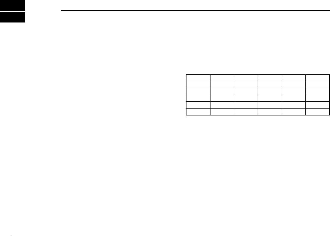
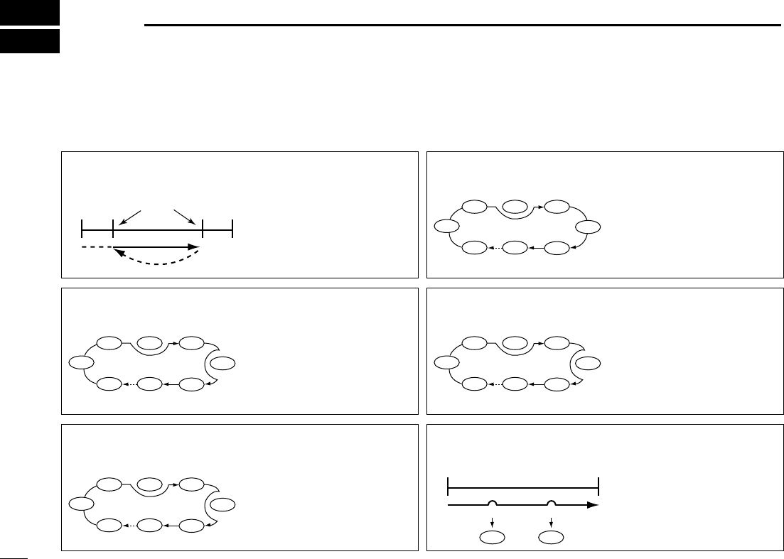
■Scan types Up to 25 programmed scan ranges, memory scan, memory
select scan, memory skip scan, mode select memory scan
and auto memory write scan provide scanning versatility.
PROGRAMMED SCAN
(p. ??)
Repeatedly scans between
two user-programmed fre-
quencies. Used for checking
for frequencies within a
specified range such as re-
peater output frequencies,
etc.
Scan
Jump
Scan edges
Scan edge Scan edge
SELECT MEMORY SCAN
(p. ??)
Repeatedly scans only select
memory channels within a
memory bank. This function
can be turned ON/OFF in
[Memory SCAN] tab. Select
channels can be set in the
memory list screen.
Not yet
programmed
ch 50
ch 1 ch 2 ch 3
ch 4
ch 5
ch 6ch 49
Not yet programmed
ch 50
ch 1 ch 2 ch 3
ch 4
ch 5
ch 6ch 49
MEMORY SKIP SCAN
(p. ??)
Skips unwanted memory
channels that inconveniently
stop scanning. This function
can be turned ON/OFF in
[Memory SCAN] tab. Skip
channels can be set in the
memory list screen.
Not yet
programmed
ch 50
ch 1 ch 2 ch 3
ch 4
ch 5
ch 6ch 49
MEMORY SCAN
(p. ??)
Repeatedly scans memory
channels within a memory
bank (0–25).
Not yet
programmed
SKIP
ch 50
ch 1 ch 2 ch 3
SEL
SEL
SKIP
SELSEL
SEL
SEL
MODE SELECT MEMORY
SCAN (p. ??)
Repeatedly scans only se-
lected mode channels within
a memory bank. This func-
tion can be set in [Memory
SCAN] tab of the setting
screen.
FM
AM
FMFMFM
FM
FM
ch 5
ch 6ch 49
ch 4
AUTO MEMORY WRITE
SCAN (p. ??)
The frequencies that the
programmed scan stops are
automatically programmed
into a selected memory
bank.
ch 1 ch 2
Pause
Program Program
Pause
Scan
!IC-PCR1500.qxd 05.10.25 10:01 AM Page 49 (1,1)

50
8
SCAN OPERATION
New2001
1
2
3
4
5
6
7
8
9
10
11
12
13
14
15
16
■Scan resume condition
When receiving a signal, scan automatically pauses on that
signal. The scan resume condition sets the time that the scan
pauses before resuming or whether scan stops instead of
pausing.
DUsing the multi-function receiver screen or
component screen
qClick the [SET] button to call up the [Scan Delay] screen if
it is not displayed.
wSelect the scan delay condition from “Pause until Signal
Disappears”, “Delay Volume” or “Scan Stop.”
(a) ‘Pause until Signal disappears’
Scan pauses when receiving a signal and remains paused
until the signal disappears.
(b) ‘Delay Volume’
When setting a delay time using the [DELAY] control (on
multi-function receiver screen or component screen), scan
pauses when receiving a signal and then resumes after the
specified delay.
(c) ‘Scan Stop’
When a signal is received during scan, scan stops and
does not resume.
eSelect a restart delay time from [Restart Delay]. This set-
ting is valid when selecting (a) or (b) in step w.
• 0 Sec. : Scan resumes immediately after the signal dis-
appears.
• 1 Sec. : Scan resumes 1 sec. after the signal disappears.
• 2 Sec. : Scan resumes 2 sec. after the signal disappears.
rClick the close ([X]) button to close the setting screen.
!IC-PCR1500.qxd 05.10.25 10:01 AM Page 50 (1,1)

51
8SCAN OPERATION
New2001
■Scan speed setting
The searching speed of frequencies or memory channels is
variable.
➥Click the [SPEED] control (on multi-function receiver
screen or component screen) to set the speed at which
scans search through frequencies/memories for signals.
• Right-click to increase the speed level.
• Left-click to decrease the speed level.
• When clicking and holding the control, the scan speed increases
or decreases continuously.
• When clicking and holding [SPEED], the scan speed scrolls up or
down.
■Programmed scan
Programmed scan automatically searches for signals within
a specified frequency range.
For programmed scan, scan edges must be programmed
in advance. See the next step for details.
DSetting scan edges
Settings such as frequency range, receive mode, tuning step,
etc. must be set in advance. Up to 50 settings can be pro-
grammed.
qRight-click the [PROG] button to call up the Program Scan
setting screen if it is not displayed.
wClick the [Program Scan] tab to show the program list.
eInput the start frequency into [Freq Low] cell from the key-
board, then push [Enter].
Other items are set automatically when [Freq Low] cell is
entered.
Program the start frequency first, otherwise no setting
can be done except for the name.
rSet data into other cells if desired, then click the close ([X])
button to close the setting screen.
!IC-PCR1500.qxd 05.10.25 10:01 AM Page 51 (1,1)

52
8
SCAN OPERATION
New2001
1
2
3
4
5
6
7
8
9
10
11
12
13
14
15
16
DStarting a programmed scan
qMake sure the squelch is set to the threshold point. (closed
condition)
wRight-click the [PROG] button to call up the Program Scan
setting screen if it is not displayed.
eClick the [Program Scan] tab to show the program list.
rEnter the programmed scan range number to be scanned
in [Program No], then click the close ([X]) button to close
the setting screen.
tClick the [PROG] button to start programmed scan.
• “PROG Scan” blinks while scanning.
yTo stop the scan, click [STOP] or [PROG].
• When the frequency is changed after cancelling a scan and a
new scan is activated, scan starts from the starting frequency of
the specified frequency range. When the frequency is not
changed, scan starts from the previously stopped frequency.
!IC-PCR1500.qxd 05.10.25 10:01 AM Page 52 (1,1)

53
8SCAN OPERATION
New2001
■Auto memory write scan
Auto memory write scan does the same as the programmed
scan and then writes paused signal frequencies into memory
channels of a specified memory bank. Scan edges must be
programmed in advance. (p. ??)
DUsing the multi-function receiver screen or
component screen
qMake sure the squelch is set to the threshold point. (closed
condition)
wRight-click the [AUTO] button to call up the Auto MW Scan
setting screen if it is not displayed.
eEnter the programmed scan range number to be scanned
in [Program No].
rSelect a memory bank to be written, then click the close
([X]) button to close the setting screen.
• To clear the selected memory bank contents, click [All Clear].
tClick the [AUTO] button to start auto memory write scan.
• “AUTO Scan” blinks while scanning.
yTo stop the scan, click [STOP] or [AUTO].
!IC-PCR1500.qxd 05.10.25 10:01 AM Page 53 (1,1)

54
8
SCAN OPERATION
New2001
1
2
3
4
5
6
7
8
9
10
11
12
13
14
15
16
■Memory/bank scan
This function searches all memory channels in a selected
memory bank.
DUsing the multi-function receiver screen or
component screen
qMake sure the squelch is set to the threshold point. (closed
condition)
wClick [BANK YY]or [BANK ZZ]to select the desired mem-
ory bank.
• When using the memory list screen, click [YY]or [ZZ], or select a
bank name with [ZZ] to select a memory bank.
eRight-click the [MEMO] button to call up the Memory Scan
setting screen if it is not displayed.
rSelect the bank scan condition from “Current Bank”, “Se-
lect Bank” or “All Bank.”
(a) ‘Current Bank’
Scans memory channels within the current bank.
(b) ‘Select Bank’
Scans memory channels within the selected bank (“Sel”
setting is turned ON in this screen).
(c) ‘All Bank’
Scans memory channels within all banks.
tMake sure the check boxes are not checked (✔), then click
the close ([X]) button to close the setting screen.
yClick the [MEMO] button to start memory scan.
• “MEMO Scan” blinks while scanning.
uTo stop the scan, click [STOP] or [MEMO].
!IC-PCR1500.qxd 05.10.25 10:01 AM Page 54 (1,1)

55
8SCAN OPERATION
New2001
■Versatile memory scan
You can set the memory scan conditions using the Memory
Scan setting screen.
qRight-click the [MEMO] button to call up the Memory Scan
setting screen if it is not displayed.
wCheck the desired check boxes, then click the close ([X])
button to close the setting screen.
• When selecting the [SEL] box (select memory scan), only se-
lected memory channels (“SEL” setting is turned ON in memory
channel list screen) are scanned.
• When selecting the [SKIP] box (memory skip scan), skip chan-
nels (“SKIP” setting is turned ON in memory channel list screen)
are not scanned.
• When selecting the [MODE SEL] box (mode select memory
scan), only memory channels that receive mode setting are
matched to [Select Mode] selection as below are scanned.
eClick the [MEMO] button to start the desired memory scan.
rTo stop the scan, click [STOP] or [MEMO].
• All settings can be used simultaneously.
• SEL, SKIP and receive mode can be set in the memory
list screen.
• At least 2 memory channels must be programmed with
the desired condition for scan to proceed.
!IC-PCR1500.qxd 05.10.25 10:01 AM Page 55 (1,1)

56
8
SCAN OPERATION
New2001
1
2
3
4
5
6
7
8
9
10
11
12
13
14
15
16
!IC-PCR1500.qxd 05.10.25 10:01 AM Page 56 (1,1)
57
PRIORITY WATCH
New2001New2001
9
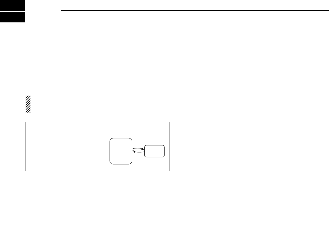
■Priority watch types
Priority watch checks for signals on the frequency every
5 sec. while operating on a VFO frequency or scanning. The
receiver has 2 priority watch types to suit your needs.
The watch resumes according to the selected scan resume
condition. See p. ?? for details.
NOTE: If the pocket beep function is activated, the receiver
automatically selects the tone squelch function when pri-
ority watch starts.
■Priority watch operation
DUsing the multi-function receiver screen or
component screen
qSet the receive frequency. (pgs. ??, ??)
wRight-click the [PRIO] button to call up the Priority Scan
setting screen if it is not displayed.
eSet the watching channel in [Scan Channel].
rSet the watching interval from 2 to 60 sec in [Priority Inter-
val], then click the close ([X]) button to close the setting
screen.
tClick the [PRIO] button to start priority scan.
• “PRIO Scan” blinks while scanning.
• The receiver checks the memory channel according to the set-
ting interval.
• The watch resumes according to the selected scan resume con-
dition. (p. ??)
• While the watch is pausing, pushing [??] resumes the watch
manually.
yTo stop the scan, click [STOP] or [PRIO].
MEMORY CHANNEL WATCH
While operating on a frequency,
priority watch checks for a signal
on the selected memory channel
every 2 to 60 sec.
• A memory channel with skip infor-
mation can be watched.
5 sec.
VFO
frequency
Memory
channel
!IC-PCR1500.qxd 05.10.25 10:01 AM Page 57 (1,1)

58
9
PRIORITY WATCH
1
2
3
4
5
6
7
8
9
10
11
12
13
14
15
16
New2001
!IC-PCR1500.qxd 05.10.25 10:01 AM Page 58 (1,1)

59
TONE SQUELCH OPERATION
New2001
10
■Tone/DTCS squelch operation
The tone or DTCS squelch opens only when receiving a sig-
nal with the same pre-programmed subaudible tone or DTCS
code, respectively in FM mode. You can silently wait for the
specified signal using the same tone.
DTone squelch frequency setting
qClick [FM] to select FM mode.
wClick [TSQL] to turn the tone squelch ON.
• “TSQL” appears in the function display.
eRight-click [TSQL] to display the [TSQL] setting screen.
rClick [ZZ]to select the desired tone squelch frequency.
• 51 tone frequencies from 67.0 to 254.1 Hz are available.
tCheck the [Reverse Action] check box to mute the received
audio signal when the received signal’s tone is matched.
•“”appears in the function display.
yClick the close button ([X]) to close the [TSQL] setting
screen.
uWhen the received signal includes a matching tone,
squelch opens and the signal can be heard.
• When the [Reverse Action] check box is checked in step t, the
received audio signal is muted.
• When the received signal’s tone does not match, tone squelch
does not open, however, the S-indicator shows signal strength.
iClick [TSQL] again to cancel the tone squelch.
• “TSQL” disappears.
•Available tone squelch frequencies list
67.0
69.3
71.0
71.9
74.4
77.0
79.7
82.5
85.4
88.5
91.5
94.8
097.4
100.0
103.5
107.2
110.9
114.8
118.8
123.0
127.3
131.8
136.5
141.3
146.2
151.4
156.7
159.8
162.2
165.5
167.9
171.3
173.8
177.3
179.9
183.5
186.2
189.9
192.8
196.6
199.5
203.5
206.5
210.7
218.1
225.7
229.1
233.6
241.8
250.3
254.1
!IC-PCR1500.qxd 05.10.25 10:01 AM Page 59 (1,1)

60
10
TONE SQUELCH OPERATION
New2001
1
2
3
4
5
6
7
8
9
10
11
12
13
14
15
16
DDTCS code setting
qClick [FM] to select FM mode.
wClick [DTCS] to turn the DTCS squelch ON.
• “DTCS” appears in the function display.
eRight-click [DTCS] to display the [DTCS] setting screen.
rClick the [ZZ]to select the desired DTCS code.
• 104 DTCS code from 023 to 754 are available.
tCheck the [Reverse Action] check box to mute the received
audio signal when the received signal’s tone is matched.
•“”appears in the function display.
yClick the close button ([X]) to close the [DTCS] setting
screen.
uWhen the received signal includes a matching code,
squelch opens and the signal can be heard.
• When the [Reverse Action] check box is checked in step t, the
received audio signal is muted.
• When the received signal’s code does not match, tone squelch
does not open, however, the S-indicator shows signal strength.
iClick [DTCS] again to cancel the DTCS squelch.
• “DTCS” disappears.
•Available DTCS code list
023
025
026
031
032
036
043
047
051
053
125
131
132
134
143
145
152
155
156
162
245
246
251
252
255
261
263
265
266
271
356
364
365
371
411
412
413
423
431
432
506
516
523
526
532
546
565
606
612
624
054
065
071
072
073
074
114
115
116
122
165
172
174
205
212
223
225
226
243
244
274
306
311
315
325
331
332
343
346
351
445
446
452
454
455
462
464
465
466
503
627
631
632
654
662
664
703
712
723
731
732
734
743
754
!IC-PCR1500.qxd 05.10.25 10:01 AM Page 60 (1,1)

61
10 TONE SQUELCH OPERATION
New2001
■DTCS polarity setting
As well as a code setting, the polarity setting is also available
for the DTCS operation. When a different polarity is set, the
DTCS never releases audio mute even when a signal with a
matching code number is received.
qClick [FM] to select FM mode.
wClick [DTCS] to turn the DTCS squelch ON.
• “DTCS” appears in the function display.
eRight-click [DTCS] to display the [DTCS] setting screen.
rSelect the DTCS polarity from “Normal” and “Reverse” in
[Polarity].
tClick the close button ([X]) to close the [DTCS] setting
screen.
■Pocket beep operation
This function uses subaudible tones for calling and can be
used as a “common pager” to inform you that someone has
called while you were away from the receiver.
qClick [FM] to select FM mode.
wClick [TSQL]/[DTCS] to turn the tone/DTCS squelch ON.
• “TSQL”/“DTCS” appears in the function display.
eRight-click [TSQL]/[DTCS] to display the [TSQL]/[DTCS]
setting screen.
rCheck the [P.Beep] check box to turn the pocket beep func-
tion ON.
•“”appears in the function display.
tClick the close button ([X]) to close the [TSQL]/[DTCS] set-
ting screen.
!IC-PCR1500.qxd 05.10.25 10:01 AM Page 61 (1,1)

62
11
BAND SCOPE
1
2
3
4
5
6
7
8
9
10
11
12
13
14
15
16
■Operation
The band scope function allows you to visually check a spec-
ified frequency range or receiving signal condition on the
specified time period.
Receive audio is muted while monitoring the band scope.
Push the pause button ([❙❙]) to pause sweeping and re-
ceive the audio.
DUsing the frequency indication on the multi-
function receiver screen or component
screen
qClick [FREQ] to select the indication of the receiving signal
relative to signal strength while sweeping.
wClick the sweep start button ([≈≈]) to begin a sweep; signal
conditions appear starting from the center of the range.
• Conditions over the entire set frequency span can be observed
around the center frequency of the currently received frequency.
eClick [SPAN +] or [SPAN –]to select the sweep width
through SPAN1 (±25.0 kHz) to SPAN6 (±500 kHz).
rClick [TS YY]or [TS ZZ]to select the sweep tuning step.
• “LIMIT” appears when a tuning step larger than the sweep step
range is selected.
tClick the waveform to select the frequency of the signal.
• Click [❙❙] to pause a sweep and monitor the frequency. Repeat
to resume the sweep.
• While pausing the band scope, you can select the frequency by
clicking the waveform. The current receive frequency is marked
by a dotted line and the previous receive frequency is displayed
at center.
yClick the sweep stop button ([‘]) to stop a sweep.
DAbout the limit indicator
When using the band scope function and the selected tuning
step (TS) is outside the automatic sweep step setting, [LIMIT]
appears in the band scope display. This indicates that the tun-
ing step (TS) and the sweep step width are not the same.
!IC-PCR1500.qxd 05.10.25 10:01 AM Page 62 (1,1)

63
11 BAND SCOPE
New2001
DUsing the time indication on the multi-
function receiver screen or component
screen
qClick [TIME] to select the indication of the receiving signal
condition on the specified time period while sweeping.
wClick the sweep start button ([≈≈]) to begin a sweep; signal
conditions appear starting from the center of the range.
• Conditions over the entire set frequency span can be observed
around the center frequency of the currently received frequency.
eClick [TIME +] or [TIME –]to select the time interval
through 100 min to 50 min, 30 min to 15 min, 10 min to 5
min and 3 min to 1.5 min.
tClick the waveform to select the frequency of the signal.
• Click [❙❙] to pause a sweep and monitor the frequency. Repeat
to resume the sweep.
• While pausing the band scope, you can also select the frequency
by clicking the waveform. The current receive frequency is
marked by a dotted line and the previous receive frequency is
displayed at center.
yClick the sweep stop button ([‘]) to stop a sweep.
■Changing the automatic
sweep step limit
The frequency steps used while sweeping are automatically
set according to the tuning step. However, these steps can
be defined using the [BAND Scope] tab on the setting screen.
qRight-click the [FREQ] button to call up the Band Scope
setting screen if it is not displayed.
wClick the desired frequency step range from in the [Auto-
matic Sweep Step Limit].
• The sweep step range can be selected from one of 1 kHz to 100
kHz, 1 kHz to 50 kHz or 1 kHz to 25 kHz.
rClick the close ([X]) button to close the setting screen.
!IC-PCR1500.qxd 05.10.25 10:01 AM Page 63 (1,1)

64
11
BAND SCOPE
New2001
1
2
3
4
5
6
7
8
9
10
11
12
13
14
15
16
■Band scope option
The following optional functions are available for the band
scope function. These settings can be defined using the
[Band Scope] screen.
●WFM Monitor function
The band scope function is normally used in AM and FM
modes only. this function allows it to be used as waveform
monitor in WFM mode.
●1/2 sweep step function
This function sets the sweep step in half of the tuning step,
doubling the sweep resolution.
qRight-click the [FREQ] button to call up the Band Scope
setting screen if it is not displayed.
wCheck the desired check boxes in [Option], then click the
close ([X]) button to close the setting screen.
eClick the close ([X]) button to close the setting screen.
■Pick up signal function
When you find a signal you want to listen to when using the
band scope function, click over the signal location in the band
scope display. The receive frequency moves to that fre-
quency.
While pausing the band scope, you can also select the dis-
played signal frequency by clicking the waveform. In this
case, the receive frequency is marked by a dotted line and
the previously received frequency is displayed at center.
!IC-PCR1500.qxd 05.10.25 10:01 AM Page 64 (1,1)

65
11 BAND SCOPE
New2001
■
Saving the sweeping data
The band scope sweep data can be stored as a PC file.
DUsing the multi-function receiver screen or
component screen
qClick the recording start button ([●]) to start recording the
receiving signal contents while sweeping.
• You can save the recording contents with the desired file name in
the [File Name] box.
• The following data are saved.
- Recording start day and time
- Center frequency
- Sweeping frequency
- Sweeping time
- Electrolytic strength
wClick the recording stop button ([‘]) to stop recording.
!IC-PCR1500.qxd 05.10.25 10:01 AM Page 65 (1,1)

66
12
DTMF OPERATION
1
2
3
4
5
6
7
8
9
10
11
12
13
14
15
16
■Operation
The computer can be remotely controlled using DTMF codes
in FM mode. When receiving a programmed DTMF code, the
IC-PCR1500 displays a message, activates a program/screen
saver or plays a Windows' sound file.
qSelect FM mode.
wClick “ ” on the tool bar to call up the [DTMF Remote
Commander] screen if it is not displayed.
eClick [ON/OFF] on the DTMF Remote Commander screen
to toggle the DTMF decoder circuit ON and OFF (the LED
lights when the function is ON).
rClick the [REMOTE] button to toggle the DTMF remote
function ON and OFF (the LED lights when the function is
ON).
NOTE: When receiving a signal including a DTMF code,
the received code is displayed in the DTMF indicator win-
dow. Up to 24 digits of the latest received DTMF code are
displayed.
DSetting the DTMF receive code
qClick “ ” on the tool bar to call up the [DTMF Remote
Commander] screen if it is not displayed.
wClick [SET] to call up the receive code setting screen.
eClick the desired tab from [1] to [5] for the receive code
setting.
rEnter the desired key code in the [Receive CODE] field
using the keyboard.
• 0 to 9, A, B, C, D, E (∗) and F (#) can be used.
tSelect the desired action from “Display Message”, “Action
Execute File” or “Play.WAV File” when the received code is
matched to the [Receive CODE] setting.
(a) ‘Display Message’
To display a entered message in the text box.
(b) ‘Action Execute File’
To execute a file, enter the file name, including full path
name, or select a desired file after pushing the [..] but-
ton.
(c) ‘Play.WAV File’
To play a file, enter the file name, including full path
name, or select a desired file after pushing the [..] but-
ton.
yClick the close button ([X]) to close the DTMF Remote
Commander screen.
!IC-PCR1500.qxd 05.10.25 10:01 AM Page 66 (1,1)

67
AUDIO SETTING SCREEN
New2001New2001
13
■Operation
The Audio Setting screen can be set the AF gain for the re-
ceiver/PC, mute function ON/OFF, beep emission condition
and beep emission type.
DTo calling up the audio setting screen
➥Click “ ” on the tool bar to call up the [Audio Setting]
screen if it is not displayed.
■The AF gain/mute setting
qCall up the [Audio Setting] screen if it is not displayed as at
left.
wClick [Receiver] or [PC] radio button to select the AF gain
setting for the receiver or PC.
eClick [Ω]/[≈] to adjust the AF gain level.
rCheck the [Mute] check box to turn the mute function
ON/OFF. When this function is turned ON, the received
audio signal is muted.
• “MUTE” appears.
tClick the close button ([X]) to close the Audio Setting
screen.
!IC-PCR1500.qxd 05.10.25 10:01 AM Page 67 (1,1)

68
13
AUDIO SETTING SCREEN
1
2
3
4
5
6
7
8
9
10
11
12
13
14
15
16
New2001
■Beep setting
qCall up the [Audio Setting] screen if it is not displayed as at
left.
wCheck the [Write/Clear/Error Beep] check box to turn the
beep emission ON when memory write, memory clear and
error.
eClick [...] to select the wave file to set the beep emission
type.
rEnter the beep repeat time period in [Repeat (1–60)] from 1
to 60.
tClick the close button ([X]) to close the Audio Setting
screen.
!IC-PCR1500.qxd 05.10.25 10:01 AM Page 68 (1,1)

69
SHORTCUT KEY OPERATION
New2001New2001
14
■Operation
Shortcut keys will help you to provide an easier and usually
quicker operation from a PC key board.
DTo assign a shortcut key
qClick “ ” on the tool bar to call up the [Setting] screen if it
is not displayed.
wClick [Hotkey Setting] tab to display the shortcut key list.
eSelect the category from “General”, “Tuning”, “Mode”,
“Scan” and “Recording” in [Category].
rSelect the desired action in [Action].
• Selectable items are differ according to [Category] setting.
tEnter the desired shortcut key or combination of keys that
executes a specific function in [Key].
• [Ctrl], [Shift] and [Alt] keys act as shortcut key with another key
combination.
• Some keys cannot be set as shortcut key.
• [Add] : Add the assigned shortcut key to the list.
• [Set] : Set the changing of the shortcut key content.
• [Sort] : Sort the shortcut key in the list in order.
• [Delete] : Delete the shortcut key from the list.
• [Default] : Reset the shortcut list to the default setting.
[Example]: Assign “AM mode selection” to [Ctrl] + [A] key
qSelect “Mode” in [Category].
wSelect “AM” in [Action].
eClick [Key] dialog box, then push [Ctrl] and [A] key.
• “Ctrl + A” is indicated in the [Key] dialog box.
rClick [Add] to add the shortcut combination keys to the list.
!IC-PCR1500.qxd 05.10.25 10:01 AM Page 69 (1,1)

70
15
MULTI CHANNEL MONITOR
1
2
3
4
5
6
7
8
9
10
11
12
13
14
15
16
New2001
The receiver has 250 multi channels. Total of 10 memory
banks are available for usage by group, etc., and 25 chan-
nels are assigned into a bank.
Repeatedly scans only the channels that has been entered in
the multi channel monitor screen, and makes you to check
the received signals visually.
qClick “ ” on the tool bar to call up the [Multi CH Monitor]
screen if it is not displayed.
qClick [SET] to display the [Multi CH Monitor] list screen,
then program the desired items.
tClick the close button ([X]) to close the [Multi CH Monitor]
list screen.
• The channel name, frequency and S-meter are displayed on the
programmed channel.
tClick the close button ([X]) to close the [Multi CH Monitor]
screen.
DMulti channel programming details
The multi channel programming is same as the memory
channels. See the following pages for the multi channel pro-
gramming details.
• Bank name programming (p. ??)
• Editing the memory channel list screen (p. ??)
• Saving memory channel data (p. ??)
• Opening memory channel data (p. ??)
• Creating a new memory channel data file (p. ??)
■Multi channel monitor programming
!IC-PCR1500.qxd 05.10.25 10:01 AM Page 70 (1,1)

71
15 MULTI CHANNEL MONITOR
New2001
■Multi channel monitor operation
qClick “ ” on the tool bar to call up the [Multi CH Monitor]
screen if it is not displayed.
• The channel name, frequency and S-meter are displayed on the
programmed channel.
wClick [ZZ]to select the desired bank.
eClick the [START] button to start a scan.
• “SCANNING” blinks in the dialog box.
• The [START] button changes to the [STOP] button.
• The background color is according to the receiving signal level.
- Black: Non programmed channel.
- Dark gray: S-meter level is below S3.
- Pale gray: S-meter level is above S3/below S9.
- Red: S-meter level is above S9.
rClick the desired channel screen to monitor.
• Scan is cancelled.
tClick [STOP] button to stop the scan.
!IC-PCR1500.qxd 05.10.25 10:01 AM Page 71 (1,1)

73
SPECIFICATIONS AND OPTIONS
New2001New2001
16
■Specifications
DDGENERAL
• Frequency coverage (MHz)
U.S.A : 851.000–866.9999
896.000–1299.9999
1300.000–1810.9999
1852.000–1867.9999
1897.000–2811.9999
2853.000–2868.9999
2898.000–3299.9999
France : 50.200–51.2000
87.500–108.000
144.000–146.000
430.000–440.000
1240.000–1300.000
Other than above : 0.010–3299.9999
*Guaranteed: 0.495–3000.000 MHz range only
• Type of emission : FM, AM, WFM, USB, LSB, CW
• Number of memory channels : 1050 (incl. 50 scan edges )
• Frequency resolution : 1 Hz, 10 Hz, 20 Hz, 50 Hz, 100 Hz,
500 Hz, 1 kHz, 2.5 kHz, 5 kHz, 6.25 kHz,
8.33 kHz, 9 kHz, 10 kHz, 12.5 kHz,
15 kHz, 20 kHz, 25 kHz, 30 kHz, 50 kHz,
100 kHz, 125 kHz, 150 kHz, 200 kHz,
500 kHz, 1 MHz, 10 MHz
• Operating temperature range : –10°C to +60°C; +14˚F to +140˚F
• Frequency stability : ±3 ppm (–10°C to +60°C)
• Power supply requirement : 12.0 V DC ±15%
• Current drain
(at 12.0 V DC: approx.) : standby 0.65 A (typical)
max. audio 1.2 A
• Antenna connector : BNC (50 Ω)
• Dimensions (proj. not included) : 146(W) ×41(H) ×206(D) mm
53⁄4(W)×15⁄8(H)×81⁄8(D) in
• Weight (approx.) : 1.2 kg; 2 lb 10 oz
DDRECEIVER
• Receive system : Triple-conversion superheterodyne and
down converter
• Intermediate frequencies : 1st: 266.700 MHz, 2nd: 10.700 MHz
3rd: 450 kHz (except for WFM mode)
• Sensitivity:
FM (1 kHz/3.5 kHz Dev.; 12 dB SINAD)
28.000–29.999 MHz : Less than 0.63 µV
30.000–49.999 MHz : Less than 0.63 µV
50.000–239.999 MHz : Less than 0.5 µV
240.000–279.999 MHz : Less than 0.5 µV
280.000–299.999 MHz : Less than 0.5 µV
300.000–699.999 MHz : Less than 0.5 µV
700.000–1299.999 MHz : Less than 0.63 µV
1300.000–2299.999 MHz : Less than 5.6 µV
2300.000–3000.000 MHz : Less than 18 µV
WFM (1 kHz/52.5 kHz Dev.; 12 dB SINAD)
50.000–699.999 MHz : Less than 1.4 µV
700.000–1299.999 MHz : Less than 1.8 µV
1300.000–2299.999 MHz : Less than 18 µV
2300.000–3000.000 MHz : Less than 56 µV
AM (1 kHz/30% MOD.; 10 dB S/N)
0.495–1.799 MHz : Less than 25 µV
1.800–14.999 MHz : Less than 2.5 µV
15.000–49.999 MHz : Less than 2.5 µV
50.000–299.999 MHz : Less than 2 µV
300.000–699.999 MHz : Less than 2 µV
700.000–1299.999 MHz : Less than 2.5 µV
!IC-PCR1500.qxd 05.10.25 10:01 AM Page 73 (1,1)

74
16
SPECIFICATIONS AND OPTIONS
1
2
3
4
5
6
7
8
9
10
11
12
13
14
15
16
New2001
SSB/CW (10 dB S/N)
0.495–1.799 MHz : Less than 5 µV
1.800–14.999 MHz : Less than 0.5 µV
15.000–49.999 MHz : Less than 0.5 µV
50.000–699.999 MHz : Less than 0.4 µV
700.000–1299.999 MHz : Less than 0.5 µV
• Sensitivity (threshold) :
FM (1 kHz/3.5 kHz Dev.; 12 dB SINAD)
28.000–29.999 MHz : Less than 0.63 µV
30.000–49.999 MHz : Less than 0.63 µV
50.000–239.999 MHz : Less than 0.5 µV
240.000–279.999 MHz : Less than 0.5 µV
280.000–299.999 MHz : Less than 0.5 µV
300.000–699.999 MHz : Less than 0.5 µV
700.000–1299.999 MHz : Less than 0.63 µV
1300.000–2299.999 MHz : Less than 5.6 µV
2300.000–3000.000 MHz : Less than 18 µV
WFM (1 kHz/52.5 kHz Dev.; 12 dB SINAD)
50.000–699.999 MHz : Less than 5.6 µV
700.000–1299.999 MHz : Less than 7.1 µV
1300.000–2299.999 MHz : Less than 71 µV
2300.000–3000.000 MHz : Less than 220 µV
AM (1 kHz/30% MOD.; 10 dB S/N)
0.495–1.799 MHz : Less than 18 µV
1.800–14.999 MHz : Less than 0.89 µV
15.000–49.999 MHz : Less than 0.89 µV
50.000–299.999 MHz : Less than 0.71 µV
300.000–699.999 MHz : Less than 0.71 µV
700.000–1299.999 MHz : Less than 0.89 µV
SSB/CW (10 dB S/N)
0.495–1.799 MHz : Less than 71 µV
1.800–14.999 MHz : Less than 7.1 µV
15.000–49.999 MHz : Less than 7.1 µV
50.000–699.999 MHz : Less than 5.6 µV
700.000–1299.999 MHz : Less than 7.1 µV
• Selectivity :
SSB/CW/AM More than 2.8 kHz/–6 dB (typical)
SSB/CW/AM/FM More than 6.0 kHz/–6 dB (typical)
AM/FM More than 15 kHz/–6 dB (typical)
AM/FM/WFM More than 50 kHz/–6 dB (typical)
WFM More than 230 kHz/–6 dB (typical)
• AF output power (at 12.0 V DC) : More than 0.5 W at 10% distortion with an 8 Ω
load
• Ext. speaker connectors : 2-conductor 3.5 (d) mm (1⁄8″)/8 Ω
• Data connectors : 2-conductor 3.5 (d) mm (1⁄8″)/100 K Ω
!IC-PCR1500.qxd 05.10.25 10:01 AM Page 74 (1,1)

1-1-32 Kamiminami, Hirano-ku, Osaka 547-0003, Japan
A-????-1EX
Printed in Japan
©2005 Icom Inc.
New2001
<Intended Country of Use>
■GER ■■FRA ■ESP ■SWE
■AUT ■NED ■POR ■DEN
■■GBR ■BEL ■ITA ■FIN
■IRL ■LUX ■GRE ■SUI
■NOR
<Intended Country of Use>
■■GER ■■FRA ■■ESP ■■SWE
■■AUT ■■NED ■■POR ■■DEN
■GBR ■■BEL ■■ITA ■■FIN
■■IRL ■■LUX ■■GRE ■■SUI
■■NOR
#22 Europe
#23 U.K.
<Intended Country of Use>
■■GER ■FRA ■■ESP ■■SWE
■■AUT ■■NED ■■POR ■■DEN
■■GBR ■■BEL ■■ITA ■■FIN
■■IRL ■■LUX ■■GRE ■■SUI
■■NOR
#26 France
!IC-PCR1500.qxd 05.10.25 10:01 AM Page 75 (1,1)