ICOM orporated 288800 Amateur Transmitter with Scanning Receiver User Manual
ICOM Incorporated Amateur Transmitter with Scanning Receiver
UserManual.wiki
>
ICOM orporated
>
288800 User Manual
User Manual
Navigation menu
Upload a User Manual
Namespaces
Wiki Guide
HTML
PDF
Info
Views
User Manual
Discussion / Help
Navigation
![■Auto power ON ……………………………………………… 118■Time-out timer ……………………………………………… 118■PTT lock ……………………………………………………… 118■Cloning function …………………………………………… 119■[MIC/SP] jacks ……………………………………………… 119■Resetting …………………………………………………… 12013 HM-75A REMOTE CONTROL MICROPHONE …………… 12114 TROUBLESHOOTING ……………………………………… 12215 SPECIFICATIONS ……………………………………… 123–12416 OPTIONS ………………………………………………… 125–126SUPPLIED ACCESSORIESThe following accessories are supplied with the transceiver.qHand strap ………………………………………………… 1wAntenna …………………………………………………… 1eBattery pack* ……………………………………………… 1rBattery charger* …………………………………………… 1tBelt clip (with screws) ………………………………… 1 set*Not supplied with some versions.reqtwv](https://usermanual.wiki/ICOM-orporated/288800/User-Guide-649683-Page-6.png)
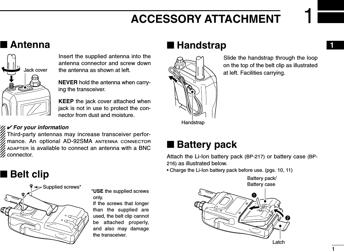
![2PANEL DESCRIPTION2■Front, top and side panelsqANTENNA CONNECTOR (p. 1)Connects the supplied antenna.• An optional AD-92SMA adapter (p. 00) is available for connect-ing an antenna with a BNC connector.wTX/RX INDICATOR [TX/RX] (p. 24)Lights green while receiving a signal or when the squelchis open; lights red while transmitting.ePTT SWITCH [PTT] (p. 24)Push and hold to transmit, release to receive.rSQUELCH KEY [SQL]➥Push and hold to open the squelch temporarily andmonitor the operating frequency. (p. 22)➥While pushing and holding this key, rotate [DIAL] to ad-just the squelch level. (p. 21)tMENU/LOCK KEY [MENU/LOCK]➥Push to toggle menu screen indication ON and OFF.(p. 85)➥Push and hold for 1 sec. to toggle the lock function ONand OFF. (p. 25)yPOWER KEY [PWR]Push and hold for 1 sec. to turn the transceiver power ONand OFF. uMAIN/DUAL KEY [MAIN/DUAL]➥Push to select the main band between A and B bands.(p. 26)➥Push and hold for 1 sec. to toggle the dualwatch func-tion ON and OFF. (p. 25)iKEYPAD (pgs. 4, 5)qw!5Function displayInternal microphoneSpeaker!2!6ertyui!4!3o!0!1!7](https://usermanual.wiki/ICOM-orporated/288800/User-Guide-649683-Page-8.png)
![32PANEL DESCRIPTION2oCALL/RX➝CS KEY [CALL/RX➝CS]➥Push to select the call channel/TV channel/weatherchannel. (p. 16)➥During DV mode operation, push and hold for 1 sec. toset the received call signs (station and repeaters) for op-eration. (p. 47)➥Enters or sends the DTMF code “C.” (p. 105)!0MEMORY/SELECT MEMORY WRITE KEY [MR/S.MW]➥Push to select memory mode. (p. 15)➥During memory mode operation, push to toggle be-tween memory and memory bank mode. (p. 68)➥Push and hold for 1 sec. to enter select memory writemode. (p. 64)➥Enters or sends the DTMF code “B.” (p. 105)!1VFO/MHz KEY [VFO/MHz]➥Push to toggle select VFO mode. (p. 15)➥During VFO mode operation, push and hold for 1 sec. toselect and toggle 1 MHz and 10 MHz tuning steps(p. 18)!2BAND KEY [BAND]➥During VFO mode operation, push to select an operat-ing frequency band. (pgs. 16, 17)➥During memory mode, push to select a memory bank.(p. 68)➥Enters or sends the DTMF code “D.” (p. 105)!3EXTERNAL DC IN JACK [DC IN]➥Connects the supplied wall charger, BC-167, to chargethe attached battery pack. (p. 10)➥Connect an external DC power supply through the op-tional CP-12L or CP-19R for external DC operation.(p. 13)!4DATA JACK [DATA]Connects a PC through the optional data communicationcable, OPC-1529, for slow-speed data communication orcontrol the transceiver remotely using with the operationalRS-91 (OPC-1529 is supplied). (p. 56)!5VOLUME CONTROL [VOL]Rotate to adjust the audio output level. (p. 20)!6CONTROL DIAL [DIAL]➥Rotate to tune the operating frequency. (p. 18)➥While pushing and holding [BAND], selects the operat-ing band in VFO mode. (p. 18)➥While scanning, changes the scanning direction. (p. 75)➥While pushing and holding [SQL], sets the squelchlevel. (p. 21)➥While pushing and holding [BAND], selects the pro-grammed bank in memory mode. (p. 68)!7EXTERNAL SPEAKER/MICROPHONE JACK [MIC/SP]Connect an optional speaker-microphone or headset, if de-sired.See pgs. 125 and 126 for a list of available options.](https://usermanual.wiki/ICOM-orporated/288800/User-Guide-649683-Page-9.png)
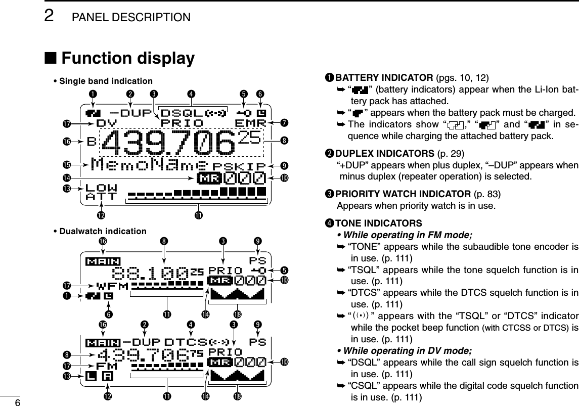
![42PANEL DESCRIPTIONDDKEYPADKEY Pushed momentarily Pushed and held for 1 sec.• Inputs digit ‘1’ for frequency input, memory channel selection,etc.• While pushing [PTT], this key sends the DTMF code “1.”• Inputs digit ‘2’ for frequency input, memory channel selection,etc.• While pushing [PTT], this key sends the DTMF code “2.”• Inputs digit ‘3’ for frequency input, memory channel selection,etc.• While pushing [PTT], this key sends the DTMF code “3.”• Inputs digit ‘4’ for frequency input, memory channel selection,etc.• While pushing [PTT], this key sends the DTMF code “4.”• Inputs digit ‘5’ for frequency input, memory channel selection,etc.• While pushing [PTT], this key sends the DTMF code “5.”• Inputs digit ‘6’ for frequency input, memory channel selection,etc.• While pushing [PTT], this key sends the DTMF code “6.”• Displays the simple band scope and sweeps once. (p. 23)• Starts a scan. (p. 75)• Toggles the transmit output power between high and low. (p. 24)- “LOW” appears when low power is selected.- While pushing and holding this key, with [DIAL] operation alsoselects the output power.• Activates the following duplex functions in order.- Minus duplex operation— “–DUP” appears.- Plus duplex operation— “+DUP” appears.- Simplex operation— no duplex indicator appears.- While pushing and holding this key, with [DIAL] operation alsoselects the duplex function.• Turn the frequency skip function ON and OFF in VFO mode(p. 28), or set the memory channel as the following skip chan-nel in memory mode in order. (p. 28)- Skip channel— “SKIP” appears.- Frequency skip channel— “PSKIP” appears.- Non-skip channel— no skip indicator appears.• Turn the memory name, bank name indication ON and OFF.(p. 70)](https://usermanual.wiki/ICOM-orporated/288800/User-Guide-649683-Page-10.png)
![52PANEL DESCRIPTION2KEY Pushed momentarily Pushed and held for 1 sec.• Inputs digit ‘7’ for frequency input, memory channel selection,etc.• While pushing [PTT], this key sends the DTMF code “7.”• Inputs digit ‘8’ for frequency input, memory channel selection,etc.• While pushing [PTT], this key sends the DTMF code “8.”• Inputs digit ‘9’ for frequency input, memory channel selection,etc.• While pushing [PTT], this key sends the DTMF code “9.”• Inputs digit ‘0’ for frequency input, memory channel selection,etc.• While pushing [PTT], this key sends the DTMF code “0.”• Inputs MHz digit for frequency input.• While pushing [PTT], this key sends the DTMF code “F (#).”• During DV mode operation, selects the record track for voicememory. (p. 62)• While pushing [PTT], this key sends the DTMF code “E (✱).”• During FM/FM-N mode operation, selects repeater tone, tonesquelch, DTCS squelch and no tone operation in sequence.(p. 111)• During DV mode operation, selects digital call sign, digital codeand no tone operation in sequence. (p. 111)• Selects tuning step selection. (p. 18)• During FM/FM-N mode operation, starts tone scan function.(p. 114)• During DV mode operation, selects break-in operation mode.(p. 51)• During DV mode operation, set “CQCQCQ” for station’s call signfor operation.• Select DTMF memory mode. (p. 106)• During DV mode operation, keep pushing and holding until 3short and 1 long beeps are emitted to turn the EMR mode oper-ation ON. (p. 56)• Selects the operating mode.](https://usermanual.wiki/ICOM-orporated/288800/User-Guide-649683-Page-11.png)
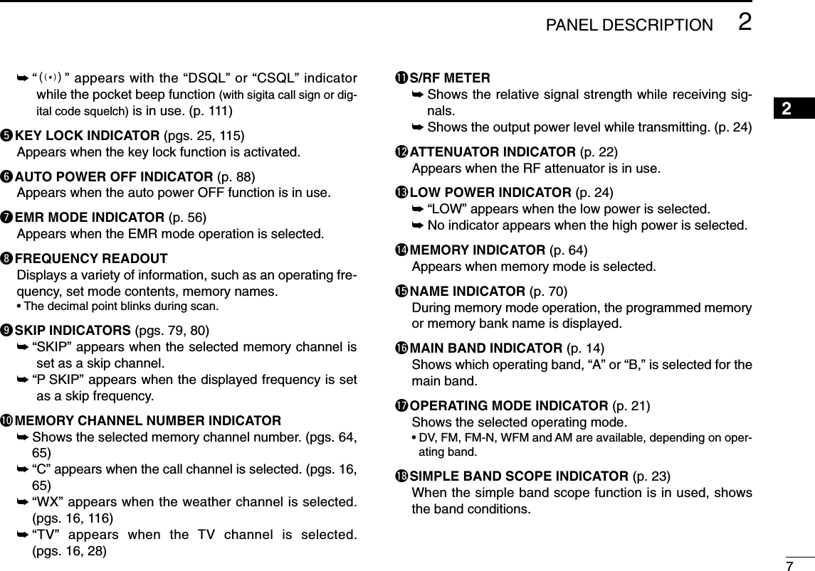
![103BATTERY CHARGING■Regular chargingPrior to using the transceiver for the first time, the batterypack must be fully charged for optimum life and operation.DDBattery indicatorsThe indicators show “ ,” “ ” and “ ” in sequencewhile charging, and both indicators disappear when com-pletely charged.DDCharging note• Be sure to turn the transceiver power OFF.Otherwise the battery pack will not be charged completely or takeslonger charging time periods.• External DC power operation becomes possible when usingan optional CP-12L, CP-19R or OPC-254L. The attachedbattery pack is also charged, except during transmit, simul-taneously. (see p. 11 for more details)• The external DC power supply voltage must within 10–16 Vto charge the battery pack and operation when using an op-tional OPC-254L.• BC-167A/D• CP-12L (Optional)• CP-19R (Optional)• OPC-254L (Optional)to AC outletto cigarette lightersocket (12 V DC)to 12 V DC(power supply)White: +Black: _Transceiverto [DC IN]Turn power OFF while charging the battery pack.• Charging time period: Approx. 5 hours](https://usermanual.wiki/ICOM-orporated/288800/User-Guide-649683-Page-16.png)
![113BATTERY CHARGING3■Rapid chargingThe optional BC-139 provides rapid charging of the batterypack.• Charging period: 2.5 hours (with BP-217)DDCharging note• Be sure to turn the transceiver power OFF.Detach the battery pack from the transceiver then chargethe battery pack itself, or charge the battery with regularcharging when the transceiver power cannot be turned OFF.Otherwise the battery pack will not be charged (charging indi-cator on the BC-139 blinks orange).• The desktop charger, BC-139, can only be charged BP-217,other types of rechargeable battery, Ni-Cd or Ni-MH, cannotbe charged.• If the charging indicator blinks orange, there may be a prob-lem with the battery pack (or charger). Reinsert the batterypack or contact your dealer.ATransceiver(with battery pack)Turn power OFF.Check the orientation.Battery packto AC outletBC-139 (optional)Desktop chargerto [AC ADAPTER]Adapter (suppliedwith BC-139)Charging indicatorCharging : OrangeFinished : GreenCharging terminalBC-123(suppliedwith BC-139)](https://usermanual.wiki/ICOM-orporated/288800/User-Guide-649683-Page-17.png)
![133BATTERY CHARGING3■External DC power operationAn optional cigarette lighter cable (CP-12L or CP-19R; for 12 Vcigarette lighter socket) or external DC power cable (OPC-254L)can be used for external power operation. DDOperating note• Power supply range is between 10.0–16.0 V DC. NEVER CONNECT OVER 16 V DC directly into [DC IN]jack of the transceiver.•BE SURE to use CP-12L,CP-19R or OPC-254L when con-necting regulated 12 V DC power supply.Purchase extra DC-DC converter if connecting the trans-ceiver through optional CP-12L, CP-19R or OPC-254L to a24 V DC power source.• The voltage of the external power supply must be within10–16 V DC when using either CP-12L, CP-19R or OPC-254L, otherwise, the attached battery pack’s power may beused for operation.• Up to 5 W (approx.) of maximum output power is providedwith the external DC power operation, however, when thesupplied voltage exceeds 14 V, the built-in protection circuitactivates to reduce the transmit output power to 0.5 W (ap-prox.).• Disconnect the cables from the transceiver when not usingit. Otherwise, the vehicle battery will become exhausted.• The power save function is deactivated automatically duringexternal DC power operation (more than 10 V DC).• CP-12L (Optional)• CP-19R (Optional)• OPC-254L (Optional)to cigarette lightersocket (12 V DC)to 12 V DC(power supply)White: +Black: _Transceiverto [DC IN]](https://usermanual.wiki/ICOM-orporated/288800/User-Guide-649683-Page-19.png)
![14FREQUENCY AND CHANNEL SETTING4■Main band selectionThe IC-91A/91AD has two independent operating band as Aband (VFO A) and B band (VFO B). A band (VFO A) can operate0.495 MHz to 999.990 MHz*, and B band (VFO B) can operate118 MHz to 174 MHz and 350 MHz to 470 MHz. *Some frequency ranges are prohibited for the USA version due tolocal regulation.DDHow to change the main band➥Push [MAIN/DUAL] to toggle between A and B band.➥Push and hold [MAIN/DUAL] for 1 sec. to turn the dual-watch operation ON and OFF.• While dualwatch operation, the display indicates the upper sideas A band and lower side as B band.➥During dualwatch operation, push [MAIN/DUAL] to selectupper side (A band) or lower side (B band) as main band (op-erating band) alternately.DTCSDTCSWPSEMWPSFMFMPRIOPRIO+DUP+DUP+DUP+DUPFM1460104400002550µ000000µ000000DTCSDTCSWPSEMEMWPSFMFMPRIOPRIO+DUP+DUP+DUP+DUPFM1460104400002550µ000000µ000000AMemoNameµPRIOPRIO WXWX EMREMRDTCSDTCSFMFMLOWLOWATTATT146010PSKIPSKIP+DUP+DUP2525000MemoNameµPRIOPRIO WXWX EMREMRDTCSDTCSFMFMBLOWLOWATTATT440000PSKIPSKIP+DUP+DUP2525000Push Push• Selecting A band • Selecting upper side as main band• Selecting lower side as main band• Selecting B bandPushDTCSDTCSWPSEMWPSFMPRIOPRIO+DUP+DUPFM146 010440 0002550µ000µ000DTCSDTCSWPSEMWPSFMPRIOPRIO+DUP+DUPFM146 010440 0002550µ000µ000AMemoNameµPRIO WX EMRDTCSFMLOWATT146010P SKIP+DUP25000MemoNameµPRIO WX EMRDTCSFMBLOWATT440000P SKIP+DUP25000Single band operation Dualwatch operationfor 1 sec.](https://usermanual.wiki/ICOM-orporated/288800/User-Guide-649683-Page-20.png)
![154FREQUENCY AND CHANNEL SETTING 4■Mode selectionDDVFO modeVFO mode is used for the desired frequency setting within thefrequency coverage.➥Push [VFO/MHz] to select VFO mode.What is VFO?VFO is an abbreviation of Variable Frequency Oscillator. Fre-quencies for both transmitting and receiving are generatedand controlled by the VFO.DDMemory modeMemory mode is used for operation of memory channelswhich have programmed frequencies.qPush [MR/S.MW] to select memory mode.•“µµ” appears when memory mode is selected.wRotate [DIAL] to select the desired memory channel.• Only programmed memory channels can be selected.• Direct memory channel entering selects the desired memorychannel. (p. 64)• See p. 66 for memory programming details.AMemoNameµPRIOPRIO WXWX EMREMRDTCSDTCSFMFMLOWLOWATTATT146010PSKIP+DUP+DUP25000000• Memory mode indicationAppearAMemoNameMemoNameµPRIOPRIO WXWX EMREMRDTCSDTCSFMFMLOWLOWATTATT146010PSKIP+DUP+DUP25000000• VFO mode indication](https://usermanual.wiki/ICOM-orporated/288800/User-Guide-649683-Page-21.png)
![164FREQUENCY AND CHANNEL SETTING DDCall/TV*/Weather†channelsCall channels are used for most-often used frequencies forquick recall. *Appears only when TV channels are programmed via theoptional RS-91. Also available for A band operation only.†Available for the USA version only.qPush [CALL/RX➝CS] several times to select call chan-nels/TV channels (A band only)/Weather channels.•Call/TV/Weather channels can be selected in sequence.wRotate [DIAL] to select the desired channel.■Operating band selectionThe transceiver can receive the AM broadcast, HF bands,50 MHz, FM broadcast, VHF air, 144 MHz, 300 MHz,400 MHz or 800 MHz* bands. (Some bands are not selectablefor B band operation. See next page for details.)➥In VFO mode, push [BAND] several times to select the de-sired frequency band.•If the other than VFO mode is selected, such as a memory chan-nel/call channel/TV channel/Weather channel, push [VFO/MHz]to select VFO mode first, then push [BAND] to select the desiredband.➥While pushing and holding [BAND], rotating [DIAL] alsoselects frequency band.Available frequency bands are different depending on ver-sion. See the specification for details. (pgs. 123, 124)*Some frequency ranges are prohibited for the USA ver-sion due to local regulation.AMemoNameµPRIOPRIO WXWX EMREMRDTCSDTCSFMFMLOWLOWATTATT146010PSKIP+DUP+DUP25000000[DIAL][DIAL]AMemoNameMemoNameµPRIOPRIO WXWX EMREMRDTCSDTCSFMFMLOWLOWATTATT146010PSKIP+DUP+DUP25C0C0TVTVAMemoNameMemoNameµPRIOPRIO WXWX EMREMRDTCSDTCSWFMWFMLOWLOWATTATT10 chPSKIP+DUP+DUP25WXWXAMemoNameMemoNameµPRIOPRIO WXWX EMREMRDTCSDTCSWFMWFMLOWLOWATTATT1PSKIP+DUP+DUP25• Call channel indication• TV channel indication• Weather channel indication](https://usermanual.wiki/ICOM-orporated/288800/User-Guide-649683-Page-22.png)
![174FREQUENCY AND CHANNEL SETTING 12345678910111213141516171819• Available frequency bandsAMemoNamePRIOPRIO WXWX EMREMRDTCSDTCSAMAM118000PSKIP+DUP+DUP25AMemoNameMemoNamePRIOPRIO WXWX EMREMRDTCSDTCSAMAMB118000PSKIP+DUP+DUP25AMemoNamePRIOPRIO WXWX EMREMRDTCSDTCSFMFMB146010PSKIP+DUP+DUP25AMemoNameMemoNamePRIOPRIO WXWX EMREMRDTCSDTCSFMFMB370000PSKIP+DUP+DUP25AMemoNamePRIOPRIO WXWX EMREMRDTCSDTCSFMFMB440000PSKIP+DUP+DUP25AMemoNameMemoNamePRIOPRIO WXWX EMREMRDTCSDTCSFMFM850000PSKIP+DUP+DUP25AMemoNameMemoNamePRIOPRIO WXWX EMREMRDTCSDTCSFMFM440000PSKIP+DUP+DUP25AMemoNameMemoNamePRIOPRIO WXWX EMREMRDTCSDTCSAMAM370000PSKIP+DUP+DUP25AMemoNameMemoNamePRIOPRIO WXWX EMREMRDTCSDTCSFMFM146010PSKIP+DUP+DUP25AMemoNameMemoNamePRIOPRIO WXWX EMREMRDTCSDTCSAMAM001620PSKIP+DUP+DUP25AMemoNamePRIOPRIO WXWX EMREMRDTCSDTCSAMAM005000PSKIP+DUP+DUP25AMemoNameMemoNamePRIOPRIO WXWX EMREMRDTCSDTCSFMFM051 000PSKIP+DUP+DUP25AMemoNamePRIOPRIO WXWX EMREMRDTCSDTCSWFMWFM076 000PSKIP+DUP+DUP25AM broadcast band HF band• A band• B band50 MHz band800 MHz band400 MHz band400 MHz bandFM broadcast bandVHF air bandVHF air band144 MHz band144 MHz band300 MHz band300 MHz band: Push: Rotating [DIAL] while pushingInitial frequencies shown differ according to version.](https://usermanual.wiki/ICOM-orporated/288800/User-Guide-649683-Page-23.png)
![184FREQUENCY AND CHANNEL SETTING ■Setting a tuning stepThe tuning step can be selected for each frequency band.The following tuning steps are available for the IC-91A/91AD.•5.0 kHz* •6.25 kHz* •8.33 kHz†•9.0 kHz‡•10.0 kHz•12.5 kHz •15.0 kHz •20.0 kHz •25.0 kHz •30.0 kHz•50.0 kHz •100.0 kHz • 125.0 kHz • 200.0 kHz* Appears for below the 600 MHz bands only. †Appears for the VHF air band only.‡Appears for the AM broadcast band only.DDTuning step selectionqPush [VFO/MHz] to select VFO mode, if necessary.wPush [BAND] to select the desired frequency band.•Or, while pushing and holding [BAND], rotate [DIAL] to selectthe desired frequency band.ePush and hold [8/TS] for 1 sec. to enter tuning step set mode.rRotate [DIAL] to select the desired tuning step.tPush [8/TS] (or [VFO/MHz]) to return to VFO mode.■Setting a frequencyDDUsing the dialqPush [VFO/MHz] to select VFO mode, if necessary.wSelect the desired frequency band with [BAND].•Or, while pushing and holding [BAND], rotate [DIAL] to selectthe desired frequency band.eRotate [DIAL] to select the desired frequency.•The frequency changes according to the preset tuning steps.See the left section for setting the tuning step.•Push and hold [VFO/MHz] for 1 sec. then rotate [DIAL] tochange the frequency in 1 MHz steps, or push and hold for 1 sec.again then rotate [DIAL] to change the frequency in 10 MHzsteps. (Each pushing and holding for 1 sec. toggles 1 MHz or10 MHz tuning steps.)APRIOPRIO WXWX EMREMRDTCSDTCSFMFM146010+DUP+DUP25APRIOPRIO WXWX EMREMRDTCSDTCSFMFM146010+DUP+DUP25[DIAL][DIAL] changes the fre-quency according to the se-lected tuning step.After pushing and holding [VFO/MHz] for 1 sec., [DIAL] changes the frequency in 1 MHz/10 MHz steps.APRIOPRIO WXWX EMREMRDTCSDTCSFMFM146010P+DUP+DUP25SET-TS:5.0kHzµ000000SKIP[DIAL]5 kHz tuning step](https://usermanual.wiki/ICOM-orporated/288800/User-Guide-649683-Page-24.png)
![194FREQUENCY AND CHANNEL SETTING 12345678910111213141516171819DDUsing the keypadThe frequency can be directly set via numeralkeys.•When editing a frequency outside of the fre-quency range, the previously displayed frequencyis automatically recalled after editing last digit.qPush [VFO/MHz] to select VFO mode, ifnecessary.wEnter the desired frequency via the keypad.APRIO WXDTCSFM730 000+DUP2525APRIO WXDTCSFM790000+DUP2525APRIO WXDTCSFM079 300+DUP2525APRIO WXDTCSFM079300+DUP2525APRIO WXDTCSFM079 300+DUP2525APRIO WXDTCSFM079 300+DUP2525APRIO WXDTCSFM146 520+DUP2525APRIO WXDTCSFM146520+DUP2525APRIO WXDTCSFM146520+DUP2525APRIO WXDTCSFM146 520+DUP2525APRIO WXDTCSFM146520+DUP2525APRIO WXDTCSFM146520+DUP2525APRIO WXDTCSFM146240+DUP2525APRIO WXDTCSFM000684+DUP2525APRIO WXDTCSFM146240+DUP2525APRIO WXDTCSFM146 240+DUP2525APRIO WXDTCSFM146240+DUP2525• Editting to 146.520 MHz• Editting to 79.3 MHz• Editting to 684 kHz• Changing 100 kHz and below.Editting 146.520 MHz to 146.240 MHzDepending on the tuning step setting, 1kHz digit may not acceptable to input. Inthis case, enter “0” as 1 kHz digit, then ro-tate [DIAL] to set the desired frequency.](https://usermanual.wiki/ICOM-orporated/288800/User-Guide-649683-Page-25.png)
![20BASIC OPERATION5■ReceivingMake sure charged battery pack (BP-217) or brand new al-kaline batteries (into BP-216) are installed (pgs. 1, 12).qPush and hold [PWR] for 1 sec. to turn power ON.wRotate [VOL] to set the desired audio level. •The frequency display shows the volume level while setting. Seethe section at right for details.eSet the receiving frequency. (p. 18)rSet the squelch level. (p. 21)•While pushing and holding [SQL], rotate [DIAL].•The first click of [DIAL] indicates the current squelch level.•“LEVEL 1” is loose squelch (for weak signals) and “LEVEL 9” istight squelch (for strong signals).•“AUTO” indicates automatic level adjustment by a noise pulsecounting system.•Push and hold [SQL] to open the squelch manually.tWhen a signal is received:•Squelch opens and audio is emitted.•The S/RF-meter shows the relative signal strength level.■Setting audio volume➥Rotate [VOL]to adjust the audio level. •If squelch is closed, push and hold [SQL] to verify the audiolevel.•The display shows the volume level while setting.µ000000VOLVOLµ000000VOLVOLµ000000VOLVOLAMemoNameµPRIOPRIO WXWX EMREMRDTCSDTCSFMFMLOWLOWATTATT146010PSKIPPSKIPPSKIPPSKIP+DUP+DUP25000000Minimum setting(no audio)Volume level indicatorMaximum setting[VOL]q [PWR]e Set frequencyr Set squelch levelw Set audio levele Select bandr Push for setting the squelch (Push to monitor)](https://usermanual.wiki/ICOM-orporated/288800/User-Guide-649683-Page-26.png)
![215BASIC OPERATION12345678910111213141516171819■Setting squelch levelThe squelch circuit mutes the received audio signal depend-ing on the signal strength. The receiver has 9 squelch levels,a continuously open setting and an automatic squelch setting.➥While pushing and holding [SQL], rotate [DIAL] to selectthe squelch level.•“LEVEL 1” is loose squelch (for weak signals) and “LEVEL 9” istight squelch (for strong signals).•“AUTO” indicates automatic level adjustment by a noise pulsecounting system.•“OPEN” indicates continuously open setting.■Operating mode selectionOperating modes are determined by the modulation of theradio signals. The transceiver has total 5 operating modes (Aband: FM, WFM and AM modes, B band FM, FM-N, AM andDV modes). The mode selection is stored independently ineach band and memory channels.Typically, AM mode is used for the AM broadcast stations(0.495–1.620 MHz) and air band (118–136.995 MHz), andWFM is used for FM broadcast stations (76–107.9 MHz).WFM mode cannot be selected above 810 MHz bands forUSA version.➥Push and hold [REC/MODE] for 1 sec. several times to se-lect the desired operating mode.AFMFM14601025AWFMWFM176 00025AAMAM11800025FM modeWFM modeAM mode• Display exampleAMemoNameMemoNameµPRIOPRIO WXWX EMREMRDTCSDTCSFMFMLOWLOWATTATT146010PSKIP+DUP+DUP25000000SQUELCH:LEVEL9µ000000PSKIPSQUELCH:AUTOµ000000PSKIPAutomatic squelchMaximum level[DIAL]](https://usermanual.wiki/ICOM-orporated/288800/User-Guide-649683-Page-27.png)
![225BASIC OPERATION■Monitor functionThis function is used to listen to weak signals without disturb-ing the squelch setting or to open the squelch manually evenwhen mute functions such as the tone squelch are in use.➥Push and hold [SQL] to monitor the operating frequency.•The 1st segment of the S-meter blinks.The [SQL] key can be set to ‘sticky’operation in set mode.See page 89 for details.■Attenuator functionThe attenuator prevents a desired signal from distorting whenvery strong signals are near the desired frequency or whenvery strong electric fields, such as from a broadcasting station,are near your location. The attenuator gain is about 10 dB.qEnter “ATTENUATOR” in set mode. (p. ?88wRotate [DIAL]†to select “ON” or “OFF.”ePush [5/SKIP](ï)(or [4/DUP](ΩΩ))to return to set mode,and push [MENU/LOCK] to return to frequency indication.• “ATT” appears on the function display when “ON” is selected.†[DIAL] ↔[2/SCAN](∫∫)/[8/TS](√√) [5/SKIP](ï)↔[6/M.N](≈≈)AMemoNameµPRIOPRIO WXWX EMREMRDTCSDTCSFMFMLOWLOWATTATT146010PSKIP+DUP+DUP25000000[DIAL]Appears.MENU screen➪SET MODE➪ATTENUATOR(Push [MENU/LOCK]) (Rotate [DIAL]†, then push [5/SKIP](ï)†.)AMemoNameMemoNameµPRIOPRIO WXWX EMREMRDTCSDTCSFMFMLOWLOWATTATT146010PSKIP+DUP+DUP25000000The 1st segment blinks](https://usermanual.wiki/ICOM-orporated/288800/User-Guide-649683-Page-28.png)
![235BASIC OPERATION12345678910111213141516171819■Band scopeThe band scope function allows you to visually check a spec-ified frequency range around the center frequency. About the sweeping steps: The specified tuning step ineach frequency band (in VFO mode) is used duringsweep.DDSingle sweepingqSet the desired frequency as band scope center frequency.wPush and hold [1/SCOPE] for 1 sec. to start single sweep-ing.•1 short and 1 long beeps sound.•Signal conditions (strengths) appear starting from the center ofthe range.eRotate [DIAL] to set the highlighted cursor to the desiredwaveform and set the frequency of the signal.rPush [VFO/MHz] to return to normal condition.DDContinuous sweepingqSet the desired frequency as band scope center frequency.wPush and hold [1/SCOPE] for 3 sec. to start continuoussweeping.•2 short beeps sound after 1 short and 1 long beeps.•Signal conditions (strengths) appear starting from the center ofthe range.ePush and hold [1/SCOPE] for 1 sec. to cancel sweeping.•Pushing [SQL] also cancels sweeping.The receive audio during sweeping can be muted insounds set mode. See page 102 for details.PRIOPRIO WXWX EMREMRDTCSDTCSFMFMBA145780P SKIPP SKIP+DUP+DUP25µ000000PRIO WX EMRDTCSFMBA145780P SKIPP SKIP+DUP2525µ000Sweep markerBand scope indication](https://usermanual.wiki/ICOM-orporated/288800/User-Guide-649683-Page-29.png)
![245BASIC OPERATION■TransmittingNOTE: To prevent interference, listen on the channel be-fore transmitting by pushing and holding [SQL].qSet the operating frequency. (pgs. 18, 19)•Transmission is available on the 144 MHz/440 MHz amateurbands only.•Select output power if desired. See the section at right for details.wPush and hold [PTT] to transmit.•Tx/Rx indicator lights red.•S/RF meter shows the output power level.eSpeak into the microphone using your normal voice level.•DO NOT hold the transceiver too close to your mouth or speaktoo loudly. This may distort the signal.rRelease [PTT] to return to receive.■Transmit power selectionThe transceiver has two output power levels to suit your op-erating requirements. Low output power during short-rangecommunications may reduce the possibility of interference toother stations and will reduce current consumption.➥Push and hold [3/LOW] for 1 sec. to toggle the transmit out-put power between High and Low.•“LOW” appears when the low power is selected.AMemoNameµPRIOPRIO WXWX EMREMRDTCSDTCSFMFMLOWLOWLOWLOWLOWLOWATTATT146010PSKIP+DUP+DUP25000000AppearsLow power transmissionHigh power transmissionTx/Rx indicatorMicrophoneCAUTION: Transmitting without an antenna will damagethe transceiver.](https://usermanual.wiki/ICOM-orporated/288800/User-Guide-649683-Page-30.png)
![255BASIC OPERATION12345678910111213141516171819■Lock functionTo prevent accidental frequency changes and unnecessaryfunction access, use the lock function. ➥Push and hold [MENU/LOCK] for 1 sec. to turn the lockfunction ON and OFF.•“ ” appears while the lock function is activated.•The squelch control and volume control can be used while thelock function is in use with default setting. Either or both thesquelch control and volume control can also be locked in setmode. (p. 90)■Dualwatch operationDualwatch operation monitors two frequencies simultane-ously. The IC-91A/91AD has two independent receiver cir-cuits as A band and B band (available frequency band oroperating mode are different depending on bands). DDDualwatch operation➥Push and hold [MAIN/DUAL] for 1 sec. to turn the dual-watch operation ON and OFF.•While dualwatch operation, the display indicates the upper sideas A band and lower side as B band.DTCSDTCSDTCSDTCSWPSPSEMWPSPSFMPRIOPRIOPRIOPRIO+DUP+DUPFMFM14601044000025255050µ000µ000AMemoNameµPRIOPRIO WXWX EMREMRDTCSDTCSFMFMLOWLOWATTATT146010PSKIP+DUP+DUP25000000AMemoNameMemoNameµPRIOPRIO WXWX EMREMRDTCSDTCSFMFMLOWLOWATTATT146010PSKIP+DUP+DUP25000000Appears](https://usermanual.wiki/ICOM-orporated/288800/User-Guide-649683-Page-31.png)
![265BASIC OPERATIONDDMain band selection➥Push [MAIN/DUAL] to select A band (upper side) or Bband (lower side) as main band (operating band) alter-nately.DDSetting audio volumeThe audio level for dualwatch operation can be adjusted bothof A band and B band synchronously (default). This setting can be set to separately for each band in soundsset mode. qPush and hold [MAIN/DUAL] for 1 sec. to enter the dual-watch operation, if necessary.wRotate [VOL] to adjust the audio level for the main band. •If squelch is closed, push and hold [SQL] to verify the audiolevel.•The display shows the volume level while setting.DTCSDTCSDTCSDTCSWPSPSEMWPSPSFMPRIOPRIOPRIOPRIO+DUP+DUPFMFM14601044000025255050µ000µ000DTCSDTCSWPSEMEMWPSPRIOPRIO+DUP+DUP+DUP+DUP2575µ000000µ000000146010DTCSDTCSWEMEMWPSPRIOPRIO+DUP+DUP+DUP+DUP2575µ000000µ000000440000FMFM440000PSPSFM146010VOLVOLVOLVOL[VOL]Setting for A band (upper side)Setting for B band (lower side)DTCSDTCSDTCSDTCSWPSPSEMWPSPSFMPRIOPRIOPRIOPRIO+DUP+DUPFMFM14601044000025255050µ000µ000DTCSDTCSDTCSDTCSWPSPSEMWPSPSFMPRIOPRIOPRIOPRIO+DUP+DUPFMFM14601044000025255050µ000µ000](https://usermanual.wiki/ICOM-orporated/288800/User-Guide-649683-Page-32.png)
![275BASIC OPERATION12345678910111213141516171819DDVolume setting for dualwatchThe volume setting for dualwatch can be select the adjust-ment both bands synchronously or each band separately insounds set mode.qEnter “VOLUME SELECT” in sounds set mode. (p. 102)wRotate [DIAL]†to select “BOTH” or “SEPARATE.”ePush [5/SKIP](ï)(or [4/DUP](ΩΩ))to return to sounds setmode, and push [MENU/LOCK] to return to frequency in-dication.DDSetting squelch levelqPush and hold [MAIN/DUAL] for 1 sec. to enter the dual-watch operation, if necessarywWhile pushing and holding [SQL], rotate [DIAL] to adjustthe main band’s squelch level.•“LEVEL 1” is loose squelch and “LEVEL 9” is tight squelch.•“AUTO” indicates automatic level adjustment with a noise pulsecount system.•“OPEN” indicates continuously open setting.DTCSDTCSWPSEMEMWPSPRIOPRIO+DUP+DUP+DUP+DUP2575µ000000µ000000SQUELCH:AUTO146010DTCSDTCSWEMEMWPSPRIOPRIO+DUP+DUP+DUP+DUP2575µ000000µ000000SQUELCH:LEVEL6440000FMFM440000PSPSFM146010DTCSDTCSDTCSDTCSWPSPSEMWPSPSFMPRIOPRIOPRIOPRIO+DUP+DUPFMFM14601044000025255050µ000µ000Setting for A band (Upper)Setting for B band (Lower)[DIAL]MENU screen➪SOUNDS➪VOLUME SELECT(Push [MENU/LOCK]) (Rotate [DIAL]†, then push [5/SKIP](ï)†.)†[DIAL] ↔[2/SCAN](∫∫)/[8/TS](√√) [5/SKIP](ï)↔[6/M.N](≈≈)](https://usermanual.wiki/ICOM-orporated/288800/User-Guide-649683-Page-33.png)
![285BASIC OPERATION■TV channel operationTV channel operation is available only when TV channels areprogrammed using the optional RS-91. (p. 125) Also availablefor A band operation only.DTV channel receivingqPush [CALL/RX➝CS] several times to select TV chan-nels.•“TV” and channel number appear.wRotate [DIAL] to select the desired channel.•While pushing and holding [BAND], rotating [DIAL] selects theall channels including skip channel.DSkip channel settingUnwanted channels can be skipped for rapid selection, etc.qPush [CALL/RX➝CS] several times to select TV chan-nels.•“TV” and channel number appear.wRotate [DIAL] to select the channel to be skipped.•To clear the skip setting, rotate [DIAL] while pushing and holding[BAND] to select a skip channel.ePush and hold [5/SKIP] for 1 sec. to toggle the skip set-ting ON and OFF.•“SKIP” appears when the channel is set as skip channel.DAutomatic TV channel programmingTV channels can be programmed automatically.qPush [CALL/RX➝CS] sev-eral times to select TV chan-nels.•“TV” and channel number ap-pear.wPush [2/SCAN] to start TVchannel programming.•The programming will automatically stop when scanning allchannels.TVTVAMemoNameµPRIOPRIO WXWX EMREMRDTCSDTCSWFMWFMLOWLOWATTATT2chPSKIP+DUP+DUP25TVTVAMemoNameµPRIOPRIO WXWX EMREMRDTCSDTCSWFMWFMLOWLOWATTATT12 chPSKIP+DUP+DUP25[DIAL] AppearsTVTVAMemoNameMemoNameµPRIOPRIO WXWX EMREMRDTCSDTCSWFMWFMLOWLOWATTATT10 chPSKIP+DUP+DUP25TV mode indicationChannel indication[DIAL]](https://usermanual.wiki/ICOM-orporated/288800/User-Guide-649683-Page-34.png)
![296REPEATER AND DUPLEX OPERATIONS12345678910111213141516171819■Repeater operationWhen using a repeater, the transmit frequency is shifted fromthe receive frequency by the offset frequency. (p. 97) It is con-venient to program repeater information into memory chan-nels. (p. 66)qSet the receive frequency (repeater output frequency).wSet the shift direction of the transmit frequency. (–DUP or+DUP; see p. 31 for details.)•When the auto repeater function is in use (U.S.A. and Koreanversions only), this selection and step eare not necessary.(p. 32)ePush and hold [7/DSQ/TONE] for1 sec. to activate the subaudibletone encoder, according to re-peater requirements.•“TONE” appears.Refer to p. 113 for tone frequencysettings.rPush and hold [PTT] to transmit.•The displayed frequency automati-cally changes to the transmit frequency (repeater input fre-quency).•If “OFF” appears, check the offset frequency or shift direction.(p. 30)tRelease [PTT] to receive.yPush and hold [SQL] to check whether the other station’stransmit signal can be directly received or not.U.S.A. and Korean versions:Auto repeater function uses the settings of the repeatertone frequency and offset frequency.ATONEFM145PSKIP-DUPATONEFM144700PSKIP-DUP300ATONETONEFMFM145300-DUP-DUP“–DUP”or “+DUP” appears.Station A Station BRepeater145.300 MHz144.700 MHz 144.700 MHz145.300 MHzUplinkDownlink(transmitting freq.)(receiving freq.)](https://usermanual.wiki/ICOM-orporated/288800/User-Guide-649683-Page-35.png)
![306REPEATER AND DUPLEX OPERATIONSDChecking the repeater input signalThe transceiver can check whether the other station’s trans-mit signal can be received directly or not.➥Push and hold [SQL] to check whether the other station’stransmit signal can be directly received or not.•When the other station’s signal can be directly received, moveto a non-repeater frequency with simplex. (duplex OFF)DDOff band indicationIf the transmit frequency is out of the amateur band, the offband indication, “OFF,” appears on the display when [PTT] ispushed. Check the offset frequency or duplex direction in thiscase. (p. 31)U.S.A. and Korean versions:Auto repeater function uses the setting of the offset fre-quency.✔CONVENIENT!Tone scan function: When you don’t know the subaudibletone used for a repeater, the tone scan is convenient for de-tecting the tone frequency.➥Push and hold [9/BK/T.SCAN] for 1 sec. to start the tonescan. See p. 114 for more information.AOFFOFFTONETONEFMFMPSKIPSKIP-DUP-DUPIndication while receiving.Receives –0.6 MHz shift frequency.Blinks while pushing and holding [SQL].ATONEFM145300PSKIP-DUPATONEFM144700PSKIP-DUPPush and hold](https://usermanual.wiki/ICOM-orporated/288800/User-Guide-649683-Page-36.png)
![316REPEATER AND DUPLEX OPERATIONS12345678910111213141516171819■Duplex operationDSetting offset frequencyqEnter “OFFSET FREQ” in DUP/TONE… set mode. (p. 97)wRotate [DIAL]†to set offset frequency.ePush [5/SKIP](ï)(or [4/DUP](ΩΩ))to return to DUP/TONE…set mode, and push [MENU/LOCK] to return to frequencyindication.DSetting duplex direction➥Push and hold [4/DUP] for 1 sec. to select “–DUP” or“+DUP”.•“–DUP” or “+DUP” indicates the transmit frequency for minusshift or plus shift, respectively.•When offset frequency is 0.6 MHz.U.S.A. and Korean versions:Auto repeater function has priority over the manual duplexsetting. If the frequency changes after setting, the auto re-peater function may have changed the duplex setting.–Duplex example +Duplex exampleReceivingTransmittingATONETONEFMFM145300PSKIPSKIP-DUP-DUPATONETONEFMFM144700PSKIPSKIP-DUP-DUPReceivingTransmittingATONETONEFMFM145300PSKIPSKIP+DUP+DUPATONETONEFMFM145900PSKIPSKIP+DUP+DUP 5.000.00 5.000.00OFFSET FREQ 0.000.00 0.000.00OFFSET FREQMENU screen➪DUP/TONE…➪OFFSET FREQ(Push [MENU/LOCK]) (Rotate [DIAL]†, then push [5/SKIP] (ï)†.)Although [DIAL] and [5/SKIP](ï)are used for descriptionin this section, [2/SCAN](∫∫)/[8/TS](√√)and [6/M.N](≈≈)areavailable instead of [DIAL] and [5/SKIP](ï).†[DIAL] ↔[2/SCAN](∫∫)/[8/TS](√√) [5/SKIP](ï)↔[6/M.N](≈≈)](https://usermanual.wiki/ICOM-orporated/288800/User-Guide-649683-Page-37.png)
![326REPEATER AND DUPLEX OPERATIONS■Auto repeater functionThe U.S.A. and Korean versions automatically activate the re-peater settings (duplex ON/OFF, duplex direction, tone encoderON/OFF) when the operating frequency falls within or outsideof the general repeater output frequency range. The offsetand repeater tone frequencies are not changed by the autorepeater function, reset these frequencies, if necessary.DFrequency range and offset direction•U.S.A. version•Korean versionqEnter “AUTO RPT” in set mode. (p. 89)wRotate [DIAL]†to select the auto repeater setting.• Push to [U.S.A. version]:•“RPT1”: Activates duplex only. (default)•“RPT2”: Activates duplex and tone.•“OFF”: Auto repeater function is turned OFF.[Korean version]:•“ON”: Activates duplex and tone. (default)•“OFF”: Auto repeater function is turned OFF.ePush [5/SKIP](ï)(or [4/DUP](ΩΩ))to return to set mode,and push [MENU/LOCK] to return to frequency indication.MENU screen➪SET MODE➪AUTO RPT(Push [MENU/LOCK]) (Rotate [DIAL]†, then push [5/SKIP] (ï)†.)U.S.A./KOREAN versions onlyFREQUENCY RANGE SHIFT DIRECTION439.000–440.000 MHz “–DUP” appearsFREQUENCY RANGE SHIFT DIRECTION147.000–147.395 MHz “+DUP” appears442.000–444.995 MHz “+DUP” appears447.000–449.995 MHz “–DUP” appears145.200–145.495 MHz146.610–146.995 MHz “–DUP” appears](https://usermanual.wiki/ICOM-orporated/288800/User-Guide-649683-Page-38.png)
 for 1 sec. to selectDTMF memory.wRotate [DIAL]†counter-clockwise until “T-CALL” appears.ePush [VFO/MHz] to exit DTMF memory.rSet the receive frequency (repeater output frequency).tSet the shift direction of the transmit frequency. (–DUP or+DUP; see p. 31 for details.)yWhile pushing [PTT], push [SQL] to transmit a 1750 Hztone burst signal.•If “OFF” appears, check the offset frequency or shift direction. (p. 97)•The displayed frequency automatically changes to the transmitfrequency (repeater input frequency).uPush and hold [PTT] to transmit.iRelease [PTT] to receive.oPush and hold [SQL] to check whether the other station’stransmit signal can be received directly or not.rT-CALLT-CALLDTMF MEMORYrCh01Ch01DTMF MEMORY†[DIAL] ↔[2/SCAN](∫∫)/[8/TS](√√) [5/SKIP](ï)↔[6/M.N](≈≈)](https://usermanual.wiki/ICOM-orporated/288800/User-Guide-649683-Page-39.png)
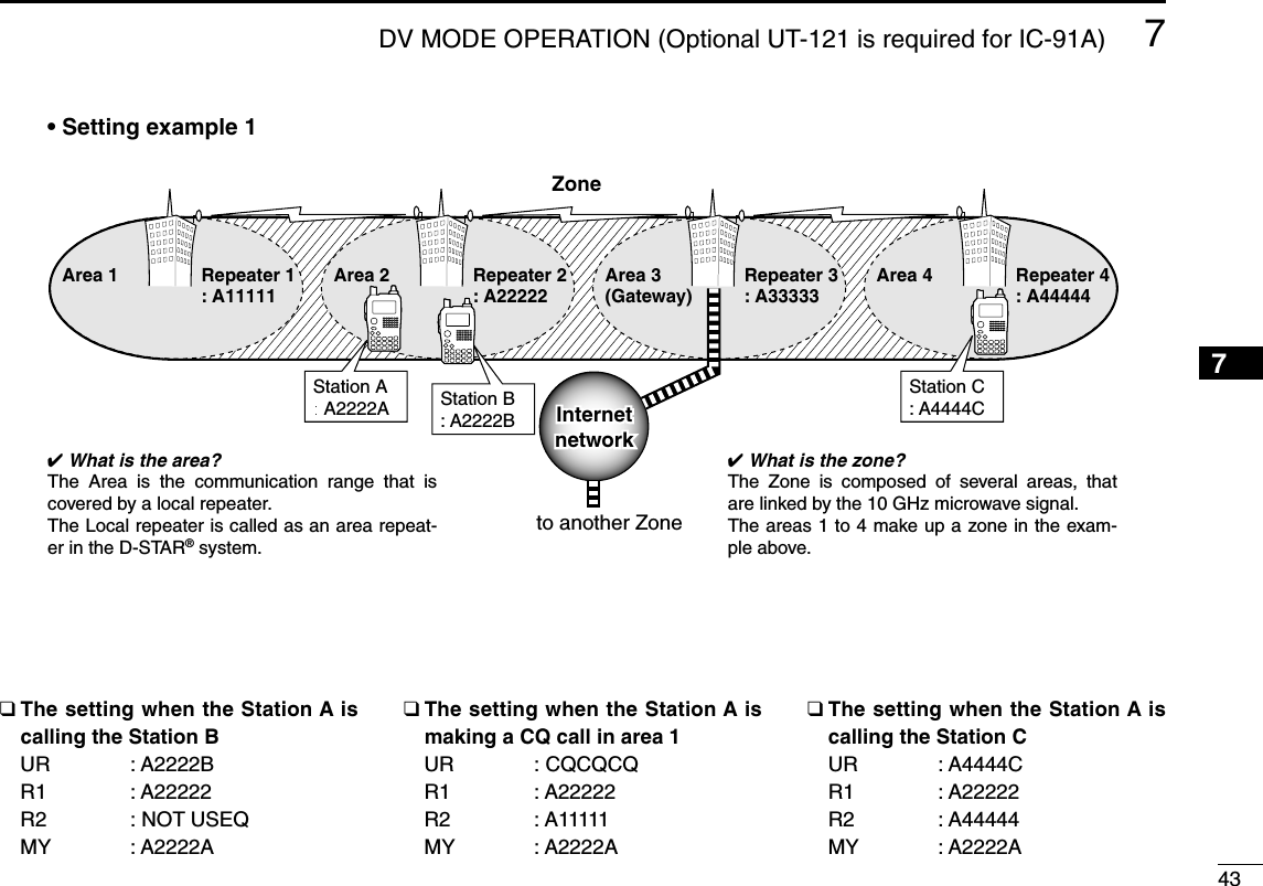
![34DV MODE OPERATION (Optional UT-121 is required for IC-91A)7■Digital mode operationThe IC-91A*/91AD can be operated for digital voice modeand slow-speed data operation for both transmit and receive.It can also be connected to a GPS receiver (compatible with anRS-232 output/NMEA format/38400 bps) and transmit/receive po-sition data.*The optional UT-121 is required for the IC-91A.■Call sign programmingFour types of call sign memories are available for your owncall sign “MY CALL SIGN,” other station call sign “YOURCALL SIGN,” repeater call sign “RPT1 CALL SIGN” and“RPT2 CALL SIGN.” “MY CALL SIGN” can store up to 6 callsigns, “YOUR CALL SIGN” can store up to 60 call signs and“RPT1/2 CALL SIGN” can store up to 60 call signs, and eachcall sign can be programmed with up to 8 characters.DDYour own call sign programmingYour own call sign must be programmed for both digital voiceand slow-speed data communications (including GPS transmis-sion).qSelect B band as the main band. (p. 14)wEnter “MY” in call sign set mode.•MY CALL SIGN screen is displayed.eRotate [DIAL]†to select the desired call sign memory,“M01” to “M06.” rPush [6/M.N](≈≈)to enter call sign programming mode.•The 1st digit blinks.tRotate [DIAL]†to select the desired character or code.•Push [3/LOW](A/a) to change the character group from “AB” (al-phabetical characters; capital letters), “12” (numbers) and “/”(symbols) in sequence.M01M01 † /MY CALL SIGNr:SET:SET:SEL:SEL:CUR:CURCLR:CLRCLR:CLRA/a:CHARA/a:CHARABM01M01 /:SET:BACK:SEL:EDITCLR:CLRMY CALL SIGNrMENU screen➪CALL SIGN➪MY(Push [MENU/LOCK]) (Rotate [DIAL]†, then push [5/SKIP](ï)†.)Although [DIAL] and [5/SKIP](ï)are used for descriptionin this section, [2/SCAN](∫∫)/[8/TS](√√)and [6/M.N](≈≈)areavailable instead of [DIAL] and [5/SKIP](ï).](https://usermanual.wiki/ICOM-orporated/288800/User-Guide-649683-Page-40.png)
to select 2nd digit, then rotate [DIAL]†toselect the desired character or code.•Push [6/M.N](≈≈)to move the cursor right; push [4/DUP](ΩΩ)tomove the cursor left.•2nd digit blinks (1st digit stops blinking).uRepeat the steps tand yto enter your own call sign.•Up to a 8-digit of call sign can be set.•If un-necessary character is entered, push [6/M.N](≈≈)or[4/DUP](ΩΩ)to select the character, then push [1/SCOPE](CLR)to erase the selected character, or push and hold[1/SCOPE](CLR) for 1 sec. to erase following all characters fromthe cursor.•When programming a note (Up to a 4-digit for operating radiotype or area, etc.), go to step !0.iPush [6/M.N](≈≈)several times to set the cursor beside “/”indication.oRepeat steps tto yto program the desired 4-characternote.!0 Push [5/SKIP](ï)to store the programmed call sign withnote and returns to MY CALL SIGN screen.!1 Push [MENU/LOCK] to return to frequency indication.M01M01 MYCALL MYCALL /IC91 /IC91:SET:BACK:SEL:EDITCLR:CLRMY CALL SIGNrM01M01 M† /MY CALL SIGNr:SET:SET:SEL:SEL:CUR:CURCLR:CLRCLR:CLRA/a:CHARA/a:CHARAB1234568910111213141516171819†[DIAL] ↔[2/SCAN](∫∫)/[8/TS](√√) [5/SKIP](ï)↔[6/M.N](≈≈)](https://usermanual.wiki/ICOM-orporated/288800/User-Guide-649683-Page-41.png)
![367DV MODE OPERATION (Optional UT-121 is required for IC-91A)DDStation call sign programming Station call sign must be programmed for the specified sta-tion call as well as repeater operation in both digital voice andslow-speed data communications.qSelect B band as the main band. (p. 14)wEnter “UR” in call sign set mode. •YOUR CALL SIGN screen is displayed.eRotate [DIAL]†to select the desired call sign memory,“U01” to “U60.” rPush [6/M.N](≈≈)to enter call sign programming mode.•The 1st digit blinks.tRotate [DIAL]†to select the desired character or code.•Push [3/LOW](A/a) to change the character group from “AB” (al-phabetical characters; capital letters), “12” (numbers) and “/”(symbols) in sequence.yPush [6/M.N](≈≈)to select 2nd digit, then rotate [DIAL]†toselect the desired character or code.•Push [6/M.N](≈≈)to move the cursor right; push [4/DUP](ΩΩ)tomove the cursor left.•2nd digit blinks (1st digit stops blinking).uRepeat the steps tand yto enter the desired station callsign.•Up to an 8-digit of call sign can be set.•If un-necessary character is entered, push [6/M.N](≈≈)or[4/DUP](ΩΩ)to select the character, then push [1/SCOPE](CLR)to erase the selected character, or push and hold[1/SCOPE](CLR) for 1 sec. to erase following all characters fromthe cursor.iPush [5/SKIP](ï)to store the programmed call sign withnote and returns to YOUR CALL SIGN screen.oPush [MENU/LOCK] to return to frequency indication.U01U01 STATION1 STATION1:SET:BACK:SEL:EDITCLR:CLRYOUR CALL SIGNrU01 AB S†:SET:SET:SEL:SEL:CUR:CURCLR:CLRCLR:CLRA/a:CHARA/a:CHAR0:CQ0:CQYOUR CALL SIGNYOUR CALL SIGNrU01U01 ABAB †:SET:SET:SEL:SEL:CUR:CURCLR:CLRCLR:CLRA/a:CHARA/a:CHAR0:CQ0:CQYOUR CALL SIGNYOUR CALL SIGNrU CQCQCQ CQCQCQ:SET:BACK:SEL:EDITCLR:CLRYOUR CALL SIGNrMENU screen➪CALL SIGN➪UR(Push [MENU/LOCK]) (Rotate [DIAL]†, then push [5/SKIP](ï)†.)](https://usermanual.wiki/ICOM-orporated/288800/User-Guide-649683-Page-42.png)
![377DV MODE OPERATION (Optional UT-121 is required for IC-91A)7NOTE: During the call sign programming mode (rto u),push [0/CQ] to set “CQCQCQ,” and push [0/CQ] again toreturn to the previously stored call sign.✔For your informationThe IC-91A/91AD has call sign edit record function.This function selects and store into a blank call sign memorychannel automatically when editing a call sign that stored in acall sign memory, regular memory or call channel with the de-fault setting. (“FULL” is displayed when all call sign memory isprogrammed.)The edited call sign can be over-written when the setting ofthe EDIT RECORD is set to OFF or SELECT. (p. 95)However, the programmed call sign in regular memory andcall channel must be over-write the regular memory and callchannel themselves. (Temporarily operation is possible.)†[DIAL] ↔[2/SCAN](∫∫)/[8/TS](√√) [5/SKIP](ï)↔[6/M.N](≈≈)1234568910111213141516171819](https://usermanual.wiki/ICOM-orporated/288800/User-Guide-649683-Page-43.png)
![387DV MODE OPERATION (Optional UT-121 is required for IC-91A)■Digital voice mode operationqSet the desired frequency in B band. (pgs. 14, 18)•Select output power, if desired. (p. 24)wSelect DV mode. (p. 21)eSet your own call sign for DV operation as follows.zEnter “MY” in call sign set mode.xRotate [DIAL]†to select the desired your own call signchannel (if you have programmed several call signs) thenpush [5/SKIP](ï)to set the call sign and return to CALLSIGN screen.•See page 34 for your own call sign programming details.rSet the desired call sign as described in “When calling thedesired station (p. 39)” or “When sending a CQ (p. 39).” tPush and hold [PTT] to transmit and speak into the micro-phone at normal voice level.•Tx/Rx indicator lights red and the RF meter shows the outputpower.yRelease [PTT] to return to receive.•The other station call sign will be received.•Received call signs can be stored into the received call recordautomatically. See page 93 for details.NOTE: The digital mode operation is vastly different fromFM mode. One of the differences is in digital mode thesquelch does not function as in FM mode. Changing thesquelch setting will not open it to hear the hiss of “WhiteNoise.” It only activates for digital squelch functions suchas CSQL (Digital code squelch) or DSQL (Digital call signsquelch).UR:UR:R1:R1:R2:NOT USE*R2:NOT USE*MY:MYCALLMY:MYCALL /IC91 /IC91CALL SIGNrMENU screen➪CALL SIGN➪MY(Push [MENU/LOCK]) (Rotate [DIAL]†, then push [5/SKIP](ï)†.)](https://usermanual.wiki/ICOM-orporated/288800/User-Guide-649683-Page-44.png)
![397DV MODE OPERATION (Optional UT-121 is required for IC-91A)7DDWhen calling the desired stationContinued instruction from step xon page 38.cRotate [DIAL]†to select “UR,” then push [5/SKIP](ï)†.•YOUR CALL SIGN screen is displayed.vRotate [DIAL]†to select the call sign channel that desiredstation’s call sign is programmed.•See page 36 for station call sign programming details.bPush [5/SKIP](ï)to set the station’s call sign and return toCALL SIGN screen.nPush [MENU/LOCK] to return to frequency indication.mOperate the instruction steps tand yon page 38.DDWhen sending a CQContinued instruction from step xon page 38.cRotate [DIAL]†to select “UR,” then push [5/SKIP](ï)†.•YOUR CALL SIGN screen is displayed.vRotate [DIAL]†to select the call sign channel that “CQC-QCQ” is programmed.Or, select “U” then push [6/M.N](≈≈)and [0/CQ] in se-quence to set “CQCQCQ.”bPush [5/SKIP](ï)to set “CQCQCQ” as the call sign andreturn to CALL SIGN screen.nPush [MENU/LOCK] to return to frequency indication.mOperate the instruction step tand yon page 38.UR:CQCQCQUR:CQCQCQR1:R1:R2:NOT USE*R2:NOT USE*MY:MYCALLMY:MYCALL /IC91 /IC91CALL SIGNrUR:STATION1UR:STATION1R1:R1:R2:NOT USE*R2:NOT USE*MY:MYCALLMY:MYCALL /IC91 /IC91CALL SIGNr†[DIAL] ↔[2/SCAN](∫∫)/[8/TS](√√) [5/SKIP](ï)↔[6/M.N](≈≈)1234568910111213141516171819](https://usermanual.wiki/ICOM-orporated/288800/User-Guide-649683-Page-45.png)
![417DV MODE OPERATION (Optional UT-121 is required for IC-91A)7■Digital repeater operationRepeater call sign must be programmed for repeater opera-tion in both digital voice and slow-speed data communica-tions.DDRepeater call sign programmingqSelect B band as the main band. (p. 00)wEnter “R1” or “R2” in call sign set mode. (p. 00)•RPT1 or RPT2 CALL SIGN screen is displayed.eRotate [DIAL]†to select the desired call sign memory,“R01” to “R60.” rPush [6/M.N](≈≈)to enter call sign programming mode.•The 1st digit blinks.tRotate [DIAL]†to select the desired character or code.•Push [3/LOW](A/a) to change the character group from “AB” (al-phabetical characters; capital letters), “12” (numbers) and “/”(symbols) in sequence.•Set “/” at the 1st digit then set the desired area repeater’s callsign (in different zone) for CQ call (“/” stands for “CQCQCQ”) in adifferent zone operation. (p. 00)yPush [6/M.N](≈≈)to select 2nd digit, then rotate [DIAL]†toselect the desired character or code.•Push [6/M.N](≈≈)to move the cursor right; push [4/DUP](ΩΩ)tomove the cursor left.•2nd digit blinks (1st digit stops blinking).uRepeat the steps tand yto enter the desired repeatercall sign.•Up to an 8-digit of call sign can be set.•Push [7/DSQ/TONE] when setting with the gateway connectionif the set repeater has gateway capability.•If un-necessary character is entered, push [6/M.N](≈≈)or[4/DUP](ΩΩ)to select the character, then push [1/SCOPE](CLR)to erase the selected character, or push and hold[1/SCOPE](CLR) for 1 sec. to erase following all characters fromthe cursor.iPush [5/SKIP](ï)to store the programmed call sign withnote and returns to RPT1 or RPT2 CALL SIGN screen.oPush [MENU/LOCK] to return to frequency indication.R01R01 RPT1AA G RPT1AA G:SET:BACK:SEL:EDITCLR:CLRRPT1 CALL SIGNrMENU screen➪CALL SIGN➪R1/R2(Push [MENU/LOCK]) (Rotate [DIAL]†, then push [5/SKIP](ï)†.)†[DIAL] ↔[2/SCAN](∫∫)/[8/TS](√√) [5/SKIP](ï)↔[6/M.N](≈≈)1234568910111213141516171819](https://usermanual.wiki/ICOM-orporated/288800/User-Guide-649683-Page-47.png)
![427DV MODE OPERATION (Optional UT-121 is required for IC-91A)DDRepeater operation in the same zoneqSet the desired repeater’s frequency, offset and shift direc-tion in B band. (p. 00)•Select DV mode in advance. (p. 00)wSet your own call sign. (p. 00)•See p. 00 for your own call sign programming.eSet the desired station call sign. (pgs. 00, 00)•See p. 00 for station call sign programming.rSet the repeater’s call sign as follows;zEnter “R1” in call sign set mode.xRotate [DIAL]†to select the nearest repeater’s call sign.cPush [5/SKIP](ï)to set the call sign for “R1.”•Return to CALL SIGN screen.vRotate [DIAL]†to select “R2” then push [5/SKIP](ï)†.•RPT2 CALL SIGN screen is displayed.bRotate [DIAL]†to select the desired repeater’s (in thesame zone) call sign.•Select “NOT USE✱” when not operating RPT2.nPush [5/SKIP](ï)to set the call sign for “R2.”•Return to CALL SIGN screen.mPush [MENU/LOCK] to return to frequency indication.tPush [PTT] to transmit; release to receive.UR:CQCQCQUR:CQCQCQR1:RPT1AAR1:RPT1AAR2:NOT USE*R2:NOT USE*MY:MYCALLMY:MYCALL /IC91 /IC91CALL SIGNrMENU screen➪CALL SIGN➪R1(Push [MENU/LOCK]) (Rotate [DIAL]†, then push [5/SKIP](ï)†.)†[DIAL] ↔[2/SCAN](∫∫)/[8/TS](√√) [5/SKIP](ï)↔[6/M.N](≈≈)](https://usermanual.wiki/ICOM-orporated/288800/User-Guide-649683-Page-48.png)
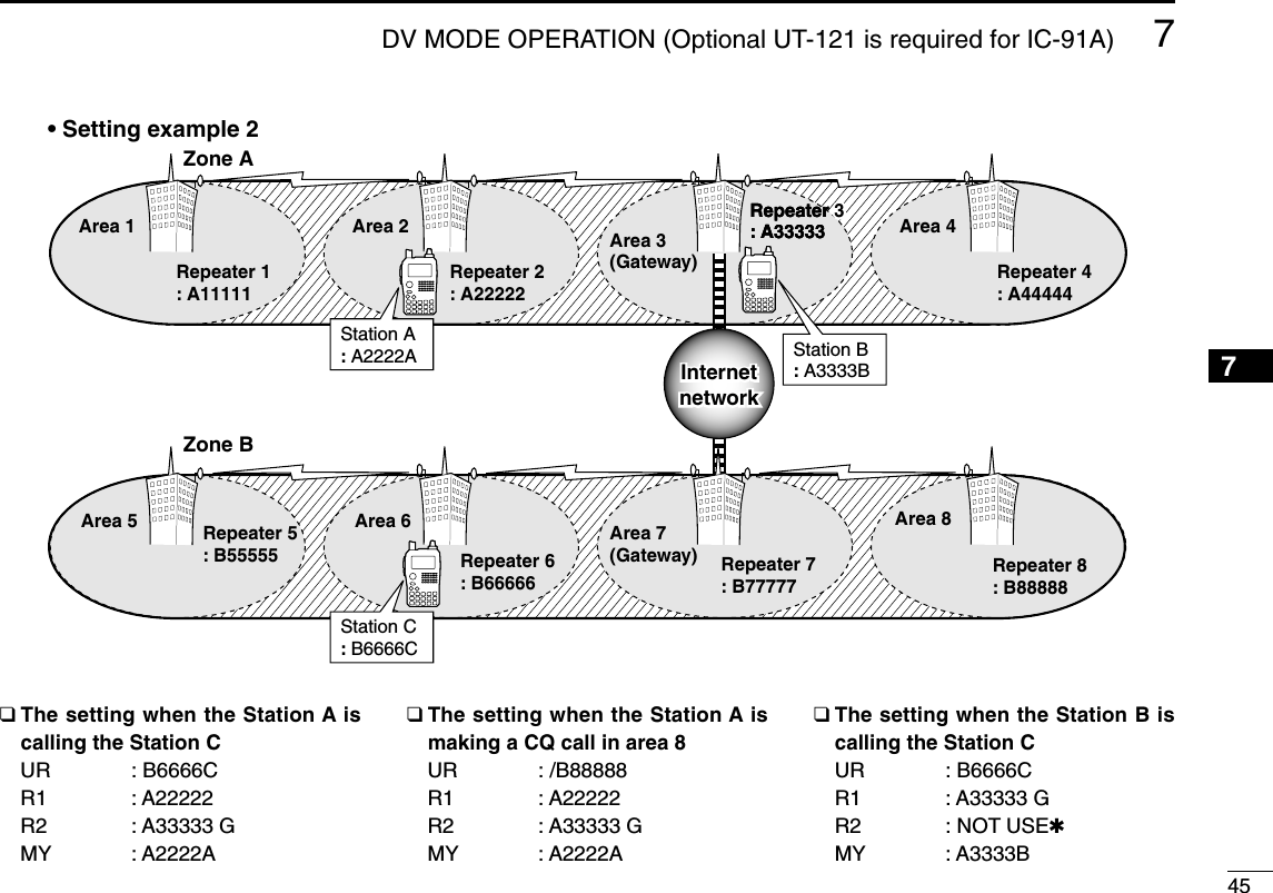
![447DV MODE OPERATION (Optional UT-121 is required for IC-91A)DDRepeater operation into another zoneqSet the desired repeater’s frequency, offset and shift direc-tion in B band. (p. 00)•Select DV mode in advance.wSet your own call sign. (p. 00)•See p. 00 for your own call sign programming.eSet the desired station call sign. (pgs. 00, 00)• When making a CQ callSet the desired repeater’s (in a different zone) call sign thathas “/” symbol at the 1st digit, for the area you want tomake a CQ call, into “UR.”•See p. 00 for station call sign programming.rSet the repeater’s call sign as follows;zEnter “R1” in call sign set mode.xRotate [DIAL]†to select the nearest repeater’s call sign.•If the nearest repeater is gateway repeater, select the re-peater’s call sign with “G” setting at the 8th digit.cPush [5/SKIP](ï)to set the call sign for “R1.”•Return to CALL SIGN screen.vRotate [DIAL]†to select “R2” then push [5/SKIP](ï)†.bRotate [DIAL]†to select the gateway repeater’s (in thesame zone) call sign.•The call sign should have “G” setting at the 8th digit.•When gateway repeater call sign is set in “R1,” select “NOTUSE✱” for “R2” setting.nPush [5/SKIP](ï)to set the call sign for “R2.”•Return to CALL SIGN screen.mPush [MENU/LOCK] to return to frequency indication.tPush [PTT] to transmit; release to receive.UR:CQCQCQUR:CQCQCQR1:RPT1AAR1:RPT1AAR2:NOT USE*R2:NOT USE*MY:MYCALLMY:MYCALL /IC91 /IC91CALL SIGNrMENU screen➪CALL SIGN➪R1(Push [MENU/LOCK]) (Rotate [DIAL]†, then push [5/SKIP](ï)†.)†[DIAL] ↔[2/SCAN](∫∫)/[8/TS](√√) [5/SKIP](ï)↔[6/M.N](≈≈)](https://usermanual.wiki/ICOM-orporated/288800/User-Guide-649683-Page-50.png)
![467DV MODE OPERATION (Optional UT-121 is required for IC-91A)■Received call signWhen a call is received in DV mode, the calling station andusing repeater call signs being used can be stored into thereceived call record. The stored call signs are viewable in thefollowing manner.Up to 20 calls can be recorded.DDDesired call record indicationqEnter RX call sign set mode.•RX CALL SIGN screen is displayed.wRotate [DIAL]†to select the desired record channel.eTo confirm the received call, push [5/SKIP](ï)severaltimes to select the desired call sign from CALLER,CALLED, RXRPT1 and RXRPT2.CALLER : The station call sign that make a call.CALLED : The station call sign that called station from thecaller.RXRPT1 : The repeater call sign near the caller station.RXRPT2 : The repeater call sign linked from the RXRPT1.rPush [MENU/LOCK] to return to frequency indication.NOTE: When a call is received in DV mode during powersave function is activated, the call sign may not be re-ceived correctly. This is normal, not a malfunction, because of header of thecall sign cannot be detected during power save.Turn the power save function OFF (p. 00) if you want to re-ceive a call sign correctly even in stand-by condition.✔For your informationWhen receive a call, the received call signs, station and re-peaters, are automatically displayed and scrolled in sequenceat the bottom line of the function display.This can be turned OFF in display set mode. (p.00)RX01RX01 CALLER: CALLER: AAAAAAAAAAAA /:CALLED :SEL:COPY CLR:CLRRX CALL SIGNrRX01RX01 CALLED: CALLED: CQCQCQCQCQCQ:RXRPT1 :SEL:COPY CLR:CLRRX CALL SIGNrRX01RX01 RXRPT2: RXRPT2: :CALLER :SEL:COPY CLR:CLRRX CALL SIGNrRX01RX01 RXRPT1: RXRPT1: :RXRPT2 :SEL:COPY CLR:CLRRX CALL SIGNrPush• Station call sign • Called station call sign• Repeater 1 call sign• Repeater 2 call signMENU screen➪RX CALL SIGN(Push [MENU/LOCK]) (Rotate [DIAL]†, then push [5/SKIP](ï)†.)†[DIAL] ↔[2/SCAN](∫∫)/[8/TS](√√) [5/SKIP](ï)↔[6/M.N](≈≈)](https://usermanual.wiki/ICOM-orporated/288800/User-Guide-649683-Page-52.png)
![477DV MODE OPERATION (Optional UT-121 is required for IC-91A)7DDOne-touch reply using the call recordThe stored call signs in the call record can be set for opera-tion to reply to the call.qAfter receiving a call, push and hold [CALL/RX➝CS] for1 sec.Or, while pushing and holding [CALL/RX➝CS], rotate[DIAL] to select the desired call sign record•Set your own call sign (MY) in advance. (p. 00)•The call sign stored in “CALLER” is set to “UR,” “RXRPT1” is setto “R2” and “RXRPT2” is set to “R1.”•Error beeps sound when a call sign is received incorrectly, andno call sign is set in this case.wPush [PTT] to transmit; release to receive.✔For your informationWhen the call that is specifying your own call sign is received,the station and the using repeater call signs being used canbe set for operation automatically.•When “Auto Received Call sign Set” (p. 00) is set to ON, thestored station call sign in “CALLER” is set to “UR” automat-ically.•When “Auto Received Repeater Call sign Set” (p. 00) is setto ON, the stored station call sign in “RXRPT1” is set to “R2”and “RXRPT2” is set to “R1” automatically.Important!The set call signs with the “One-touch reply using the callrecord” operation as at below left are for temporary opera-tion only. Therefore, the set call signs will be erased whenanother call sign is set.•Never saved into a call sign memory.If you want to save the set call signs, see “Copying the setcall sign contents for temporary operation” (p. 00) for details.DVDVB439706PSKIPPSKIP-DUP-DUP25AAAAAAThe received call sign is displayed while pushing and holding [CALL/RX➝CS] when [DIAL] is rotated while [CALL/RX➝CS] is pushed.1234568910111213141516171819](https://usermanual.wiki/ICOM-orporated/288800/User-Guide-649683-Page-53.png)
![487DV MODE OPERATION (Optional UT-121 is required for IC-91A)■Copying the call signDDCopying the call sign memory contentsThis function is convenient when saving with additional notesfor areas (for mobile operation) or unit number/initials (if severaltransceivers are available), or modifying a part of the current callsign.NOTE: Make sure that the “EDIT RECORD” item in DV setmode is set to “AUTO” or “SELECT” in advance. (p. 00)qDuring DV mode operation, enter call sign set mode.•CALL SIGN screen is displayed.wRotate [DIAL]†to select “UR,” “R1” or “R2” as desired, thenpush [5/SKIP](ï)†.eRotate [DIAL]†to select the desired call sign channel to becopied.•M01–M06, U01–U60 and R01–R60 are available.• When “AUTO” is set to “EDIT RECORD” itemrPush [6/M.N](≈≈)to select the call sign programming mode.•A blank channel is selected automatically.•The 1st digit of the selected call sign blinks.tEdit or modify the selected call sign as described in “DSta-tion call sign programming” (p. 00) or “DRepeater call signprogramming” (p. 00).yPush [5/SKIP](ï)to store the edited/modified call sign intothe selected blank channel.NOTE: The message “FULL” is displayed when no blankchannel is available in station or repeater call sign mem-ory.Select the desired call sign channel number as describedin step uof “• When “SELECT” is set to “EDIT RECORD”item” at right page in this case.U21 AB †AAAAAAAAAA:SET:SET:SEL:SEL:CUR:CURCLR:CLRCLR:CLRA/a:CHARA/a:CHAR0:CQ0:CQYOUR CALL SIGNYOUR CALL SIGNrA blank channelnumber blinks.MENU screen➪CALL SIGN(Push [MENU/LOCK]) (Rotate [DIAL]†, then push [5/SKIP](ï)†.)](https://usermanual.wiki/ICOM-orporated/288800/User-Guide-649683-Page-54.png)
to select the call sign programming mode.•The 1st digit of the selected call sign blinks.tEdit or modify the selected call sign as described in “DSta-tion call sign programming” (p. 00) or “DRepeater call signprogramming” (p. 00).yPush [5/SKIP](ï).• Call sign channel number blinks.uRotate [DIAL]†to select the desired call sign channel tostore.iPush [5/SKIP](ï)to store the edited/modified call sign intothe selected channel.U21U21 ABAB AAAAA1 AAAAA1:SET:SET:SEL:SEL:CUR:CURCLR:CLRCLR:CLRA/a:CHARA/a:CHAR0:CQ0:CQYOUR CALL SIGNYOUR CALL SIGNrCall sign channelnumber bliks.†[DIAL] ↔[2/SCAN](∫∫)/[8/TS](√√) [5/SKIP](ï)↔[6/M.N](≈≈)1234568910111213141516171819](https://usermanual.wiki/ICOM-orporated/288800/User-Guide-649683-Page-55.png)
to select copy select mode.•COPY SELECT screen is displayed.eRotate [DIAL]†to select the desired call sign to be copiedfrom “ALL,” “RXRPT1” and “RXRPT2.”•“ALL” selection won’t be appeared when either station or re-peater call sign memory has no blank channel.• When “ALL” is selected➥Push [6/M.N](≈≈)to copy the selected record’s contentsinto the appropriate call sign memory.•Returns to RX CALL SIGN screen automatically.• When “CALLER,” “RXRPT1” or “RXRPT2” is selectedzPush [6/M.N](≈≈)then rotate [DIAL]†to select the desiredcondition of call sign memory channel selection to becopied to from “AUTO” and “LIST SEL.”•“AUTO” selection won’t be appeared when the appropriate callsign memory has no blank channel.•Go to step rwhen “AUTO” is selected.xPush [6/M.N](≈≈), then select the desired call sign mem-ory channel to copy to with [DIAL].cPush [6/M.N](≈≈)to copy the call sign into the selectedcall sign memory.•Returns to RX CALL SIGN screen automatically.rPush [MENU/LOCK] to return to frequency indication.RX01RX01AUTOAUTOLIST SELLIST SEL:BACK:BACK:LIST:LISTCOPY SELECTCOPY SELECT:SEL:SELrRX01RX01ALLALL:BACK:BACK:LIST:LIST C:CURRC:CURRCOPY SELECTCOPY SELECT:SEL:SELr†[DIAL] ↔[2/SCAN](∫∫)/[8/TS](√√) [5/SKIP](ï)↔[6/M.N](≈≈)](https://usermanual.wiki/ICOM-orporated/288800/User-Guide-649683-Page-56.png)
![517DV MODE OPERATION (Optional UT-121 is required for IC-91A)7■Break-in communicationThe break-in function allows you to break into a conversation,where the two original stations are communicating with callsign squelch enabled (p. 00).qWhile receiving an another station’s communication, pushand hold [CALL/RX➝CS] for 1 sec. to set the communi-cating station’s call sign.•When a call sign has not been received correctly, error beepssound and no call sign is set. Receive the call sign included in acommunicating signal again, or set the call sign manually in thiscase.wPush and hold [9/T.SCAN/BK] for 1 sec. to turn the break-in function ON.•“BK” appears.eWhen both stations are in standby, push [PTT] to transmita break-in call.•Programmed call sign station receives the break-in call as wellas your call sign.rWait for the reply call from the station who receives thebreak-in call.tAfter receiving the reply call, communicate normally.yTo cancel the break-in, push and hold [9/T.SCAN/BK] for1 sec. to turn OFF.BKBKDVDVBLOWLOWATTATT430712PSKIPPSKIP50 Appears• How to use the break-in?While operating with the call sign squelch (p. 00), thesquelch never opens (no audio sounds) even if a call is re-ceived, unless your own call sign (“MY”) is specified.However, when the call including the “BK ON” signal (break-in call) is received, the squelch will open and audio soundseven if the call is specified for another station.Station A Station BStation C• Station C calling to Station A with “BK OFF”Station A Station BStation C• Station C calling to Station A with “BK ON”Station A and B are communicating us-ing the call sign squelch.Station A and B are communicating us-ing the call sign squelch.Station B never hears that Station C is calling Station A.Station B also hears that Sta-tion C is calling Station A.1234568910111213141516171819](https://usermanual.wiki/ICOM-orporated/288800/User-Guide-649683-Page-57.png)
![527DV MODE OPERATION (Optional UT-121 is required for IC-91A)■Message operationDDTX message programmingTX messages are available for up to 6 channels and eachchannel can be programmed with a message of up to 20characters. Available characters are 0to 9, Ato Z(capital let-ters), ato z(small letters), some symbols and space.A TX message channel “Ch01” must be programmed, if youwant to use the GPS message. The GPS message is trans-mitted from Ch01 only.qEnter “TX MESSAGE” in message/position set mode.•TX MESSAGE screen is displayed.wRotate [DIAL]†to select the desired transmit messagechannel.•Ch01 to Ch06 and OFF are available.•Previously message is displayed if programmed.ePush [6/M.N](≈≈)to select the message edit condition.•The 1st digit of the message blinks.rRotate [DIAL]†to select the desired character or symbol.•Push [3/LOW](A/a) to change the character group from “AB” (al-phabetical characters; capital letters), “ab” (alphabetical charac-ters; small letters), “12” (numbers) and “!”” (symbols) insequence.•If un-necessary character is entered, push [6/M.N](≈≈)or[4/DUP](ΩΩ)to select the character, then push [1/SCOPE](CLR)to erase the selected character, or push and hold[1/SCOPE](CLR) for 1 sec. to erase following all characters fromthe cursor.tPush [6/M.N](≈≈)to select 2nd digit, then rotate [DIAL]†toselect the desired character or code.•Push [6/M.N](≈≈)to move the cursor right; push [4/DUP](ΩΩ)tomove the cursor left.•2nd digit blinks (1st digit stops blinking).yRepeat the steps rand tto enter the desired message.•Up to 20-character message can be set.uPush [5/SKIP](ï)to store the message.iPush [MENU/LOCK] to return to frequency indication.Ch01Ch01 !''Hellow!Hellow!†:SET:SET:SEL:SEL:CUR:CURCLR:CLRCLR:CLRA/a:CHARA/a:CHARTX MESSAGETX MESSAGErCh01Ch01 †:SET:SET :SEL:SEL:BACK:BACKCLR:CLRCLR:CLRTX MESSAGETX MESSAGE:EDIT:EDITrMENU screen➪MESSAGE/POSITION➪TX MESSAGE(Push [MENU/LOCK]) (Rotate [DIAL]†, then push [5/SKIP](ï)†.)](https://usermanual.wiki/ICOM-orporated/288800/User-Guide-649683-Page-58.png)
![537DV MODE OPERATION (Optional UT-121 is required for IC-91A)7DDMessage TransmissionSelect the message transmission function ON (Ch01–06) andOFF. When a message channel is selected, the transceivertransmits a text message (pre-programmed). (default: OFF) qSet the operating frequency, call signs and other settings,such as repeater, as desired in B band. (p. 00)wPerform the steps qto ein “DTX message program-ming” as at left.eRotate [DIAL]†to select the desired message channel.•“Ch01” to “Ch06” available.•See left pages for message programming.rPush [5/SKIP](ï)to set the message for transmission.tPush [PTT] to transmit the selected message.•The message is transmitted each time [PTT] is pushed.•The message is transmitted each 30 sec. automatically duringcontinuous transmission.yRelease [PTT] to return to receive.uWhen the reply call with a message is received, the callsign and the message scrolls at the bottom of the functiondisplay.✔For your informationThe automatic received call sign and/or message indicationcan be turned OFF in display set mode, if desired.➥RX CALL SIGN (p. 00)➥RX MESSAGE (p. 00)NOTE: Only 1 message can be stored in the IC-91A/91AD. The received message is cleared once turningpower OFF, or overwritten when another message is re-ceived.The transmitted message that includes small caps charac-ters from the IC-91A/91AD may not be decoded and dis-played correctly with ID-800H, IC-V82/U82, etc.DVDVB430712PSKIPPSKIP50MSG:Hellow!Scrolls the received message.†[DIAL] ↔[2/SCAN](∫∫)/[8/TS](√√) [5/SKIP](ï)↔[6/M.N](≈≈)1234568910111213141516171819](https://usermanual.wiki/ICOM-orporated/288800/User-Guide-649683-Page-59.png)
![547DV MODE OPERATION (Optional UT-121 is required for IC-91A)DDRX message indicationThe received message can also be checked in DV set mode.qSelect “RX MESSAGE” in message/position set mode.•The received message is displayed in RX MESSAGE screen.wRotate [DIAL] or push [8/TS](√√)to display the station callsign.ePush [5/SKIP](ï)or [4/DUP](ΩΩ)to return to MES-SAGE/POSITION screen.rPush [MENU/LOCK] to return to frequency indication.■Automatic reply functionThe automatic reply function replies to the call that specifiedyour own call sign is received, and the calling station call signis automatically set to reply. 2 types of replying method are available— one is making areply call with your own call sign, and other one is making areply call with reply voice audio that has been recorded in DVvoice memory.DDAutomatic reply function settingqEnter “AUTO REPLY” in DV set mode.•AUTO REPLY screen is displayed.wRotate [DIAL]†to select the desired reply condition.OFF : Deactivate the automatic reply function. (default)ON : Reply to the call with your own call sign.VOICE : Reply to the call with the recorded voice memory.ePush [5/SKIP](ï).•Returns to DV SET MODE screen automatically.rPush [MENU/LOCK] to return to frequency indication.OFFOFFONONVOICEVOICEAUTO REPLYrMENU screen➪DV SET MODE➪AUTO REPLY(Push [MENU/LOCK]) (Rotate [DIAL]†, then push [5/SKIP](ï)†.)CALLER:CALLER: BBBBBB BBBBBB /:MSG:MSG:BACK:BACKRX MESSAGERX MESSAGErMESSAGE:MESSAGE:Hellow!Hellow!:CALLER:CALLER:BACK:BACKRX MESSAGERX MESSAGErMENU screen➪MESSAGE/POSITION➪RX MESSAGE(Push [MENU/LOCK]) (Rotate [DIAL]†, then push [5/SKIP](ï)†.)](https://usermanual.wiki/ICOM-orporated/288800/User-Guide-649683-Page-60.png)
![557DV MODE OPERATION (Optional UT-121 is required for IC-91A)7DDVoice memory recording for automatic replyqEnter “RELY VOICE” in DV voice memo set mode.•REPLY VOICE screen is displayed.wWhile pushing and holding [PTT], speak into the micro-phone.•Up to 10 second message is recordable.•The recording stops after 10 second or when [PTT] is released.ePush [4/DUP](Ω)to return to DV VOICE MEMO screen.rPush [MENU/LOCK] to return to frequency indication.DDPlay-back or erase the voice memoryqPush [MENU/LOCK] to select menu mode indication.wRotate [DIAL]†to select “DV VOICE MEMO,” then push[5/SKIP](ï)†.eRotate [DIAL]†to select “REPLY VOICE,” then push[5/SKIP](ï)†.•REPLY VOICE screen is displayed.rTo play-back the recorded voice memory, push[5/SKIP](ï).•Push [5/SKIP](ï)again to pause, push [6/M.N](≈≈)to cancel theplay-back.tTo erase the recorded voice memory, push and hold[1/SCOPE](CLR) for 1 sec.REPLY VREPLY VPTT:PTT:●:BACK:BACK CLR:CLRCLR:CLRREPLY VOICEREPLY VOICE:rMENU screen➪DV VOICE MEMO➪REPLY VOICE(Push [MENU/LOCK]) (Rotate [DIAL]†, then push [5/SKIP](ï)†.)IMPORTANT!Deactivate the dualwatch function and set minimum [VOL]level when recording the DV voice memo.Otherwise the received audio or unwanted noise from Aband is also recorded into the voice memory.†[DIAL] ↔[2/SCAN](∫∫)/[8/TS](√√) [5/SKIP](ï)↔[6/M.N](≈≈)1234568910111213141516171819](https://usermanual.wiki/ICOM-orporated/288800/User-Guide-649683-Page-61.png)
![567DV MODE OPERATION (Optional UT-121 is required for IC-91A)■EMR communicationThe EMR communication mode is available for digital modeoperation. In the EMR communication mode, no call sign set-ting is necessary. When an EMR communication mode sig-nal is received, the audio (voice) will be sound in the specifiedlevel even the volume setting level is set to minimum level.qSet the desired frequency in 144 or 440 MHz band thenpush and hold [•/EMR/DTMF] until 3 short and 1 longbeeps sound to turn the EMR setting ON.•“EMR” appearswOperate the transceiver normal way.eTo cancel the EMR communication mode, push and hold[•/EMR/DTMF] for 1 sec. to turn OFF.■Slow-speed data communicationIn addition to the digital voice communication, a slow-speeddata communication is available.The optional OPC-1529 DATA COMMUNICATION CABLEand aslow-speed data communication application (purchase locally)are required additionally.The optional RS-91 REMOTE CONTROL SOFTWARE(OPC-1529supplied) also includes a slow-speed data communication ca-pability.DDConnectionConnect the transceiver to your PC using with the optionalOPC-1529 as illustrated below.OPC-1529(optional)to [DATA]jack toRS-232CEMREMRDVDVB430712PSKIPPSKIP50 Appears](https://usermanual.wiki/ICOM-orporated/288800/User-Guide-649683-Page-62.png)
![577DV MODE OPERATION (Optional UT-121 is required for IC-91A)7DDSlow-speed data communication applicationsettingSet the slow-speed data communication application as fol-lows.•Port : The same COM port number as IC-91A/91AD’s•Baud rate : 38.4 kbps (fixed value)•Data : 8 bit•Parity : None•Stop : 1 bit•Flow control : Xon/XoffDDSlow-speed data communication operationqSet your own, station call signs, etc. as described in “■Digital voice mode operation” (p. 00) and “■Digital repeateroperation” (p. 00).wRefer to the instructions of the slow-speed data communi-cation application.ePush and hold [PTT] to transmit.•The set data is transmitted with your voice audio.•Automatic transmission, transmits when text data is input intobuffer, capability is available. See right page for details.rRelease [PTT] to return to receive.DDTransmission condition settingqEnter “DV DATA TX” in DV set mode.wRotate [DIAL]†to select “PTT” or “AUTO.”ePush [5/SKIP](ï)†to set the automatic data transmission,and push [MENU/LOCK] to return to frequency indication.MENU screen➪DV SET MODE➪DV DATA TX(Push [MENU/LOCK]) (Rotate [DIAL]†, then push [5/SKIP](ï)†.)†[DIAL] ↔[2/SCAN](∫∫)/[8/TS](√√) [5/SKIP](ï)↔[6/M.N](≈≈)1234568910111213141516171819](https://usermanual.wiki/ICOM-orporated/288800/User-Guide-649683-Page-63.png)
![587DV MODE OPERATION (Optional UT-121 is required for IC-91A)■GPS operationA GPS receiver (RS-232C output/NMEA format) can be con-nected to [DATA] socket of the IC-91A/91AD to indicate thecurrent position (Latitude and Longitude). The position data canalso be transmitted with a message to another station.DDSentence formatter settingqEnter “GPS MODE” in DV set mode.•GPS MODE screen is displayed.wRotate [DIAL]†to select “ON.”ePush [5/SKIP](ï)†to select GPS SENTENCE screen.rRotate [DIAL]†to select the desired GPS sentence, thenpush [5/SKIP](ï).•A total 5 sentences, RMC, GGA, GLL, GSA and VTG are avail-able.tRotate [DIAL]†to turn the sentence usage ON and OFF.yPush [5/SKIP](ï)to set and return to GPS SENTENCEscreen.uRepeat the steps rto yto set another GPS sentenceusage.•Up to 3 GPS sentences are usable at the same time.iPush [MENU/LOCK] to return to frequency indication.OFFONGPS MODEGPS MODE:SENTENCE:SENTENCErMENU screen➪DV SET MODE➪GPS MODE(Push [MENU/LOCK]) (Rotate [DIAL]†, then push [5/SKIP](ï)†.)OPC-1529(optional)to [DATA]jack to RS-232C port(cross converteris required)GPSreceiver](https://usermanual.wiki/ICOM-orporated/288800/User-Guide-649683-Page-64.png)
to select the message edit condition.•The 1st digit of the message blinks.eRotate [DIAL]†to select the desired character or symbol.•Push [3/LOW](A/a) to change the character group from “AB” (al-phabetical characters; capital letters), “ab” (alphabetical charac-ters; small letters), “12” (numbers) and “!”” (symbols) insequence.rPush [6/M.N](≈≈)to select 2nd digit, then rotate [DIAL]†toselect the desired character or code.•Push [6/M.N](≈≈)to move the cursor right; push [4/DUP](ΩΩ)tomove the cursor left.•2nd digit blinks (1st digit stops blinking).tRepeat the steps rand tto enter the desired message.•Up to 20-character message can be set.yPush [5/SKIP](ï)to store the message.uPush [MENU/LOCK] to return to frequency indication.DATA:DATA: AB Hellow!Hellow!†:SET:SET:SEL:SEL:CUR:CURCLR:CLRCLR:CLRGPS MESSAGEGPS MESSAGEA/a:CHARA/a:CHARrDATA:DATA: ABAB †:SET:SET:SEL:SEL:CUR:CURCLR:CLRCLR:CLRGPS MESSAGEGPS MESSAGEA/a:CHARA/a:CHARrMENU screen➪MESSAGE/POSITION➪GPS(Push [MENU/LOCK]) (Rotate [DIAL]†, then push [5/SKIP](ï)†.)†[DIAL] ↔[2/SCAN](∫∫)/[8/TS](√√) [5/SKIP](ï)↔[6/M.N](≈≈)1234568910111213141516171819](https://usermanual.wiki/ICOM-orporated/288800/User-Guide-649683-Page-65.png)
![607DV MODE OPERATION (Optional UT-121 is required for IC-91A)DDGPS message automatic transmission qEnter “GPS AUTO TX” in DV set mode.•GPS AUTO RX screen is displayed.wRotate [DIAL]†to select the desired position data transmit-ting interval from 5 sec., 10 sec., 30 sec., 1 min., 3 min.,5 min., 10 min., 30 min. and OFF.•The position data won’t be transmitted when OFF is selected, thedata is transmitted in each 5 sec., 10 sec., 30 sec., 1 min.,3 min., 5 min., 10 min. and 30 min. when the appropriate settingis selected.•The GPS message is also transmitted if programmed.ePush [5/SKIP](ï)to set the time interval and return to DVSET MODE screen.rPush [MENU/LOCK] to return to frequency indication.DDPosition indicationqEnter “POSITION” in message/position set mode.•GPS POSITION screen is displayed.wRotate [DIAL]†to select the received position data indica-tion.ePush [5/SKIP](ï)to return to MESSAGE/POSITIONscreen.rPush [MENU/LOCK] to return to frequency indication.MY POSITIONGPS POSITIONGPS POSITIONr34.56.789 N34.56.789 N123.45.678 E123.45.678 E:RX POS:RX POS:BACK:BACKMENU screen➪MESSAGE/POSITION➪POSITION(Push [MENU/LOCK]) (Rotate [DIAL]†, then push [5/SKIP](ï)†.)OFF5SEC5SEC10SEC10SEC30SEC30SEC1MIN1MINGPS AUTO TXGPS AUTO TXrMENU screen➪DV SET MODE➪GPS AUTO TX(Push [MENU/LOCK]) (Rotate [DIAL]†, then push [5/SKIP](ï)†.)](https://usermanual.wiki/ICOM-orporated/288800/User-Guide-649683-Page-66.png)
to return to MESSAGE/POSITIONscreen.ePush [MENU/LOCK] to return to frequency indication.DATA:DATA: Call from Call from Osaka! Osaka!:BACK:BACKRX GPS MESSAGERX GPS MESSAGErMENU screen➪MESSAGE/POSITION➪RX GPS(Push [MENU/LOCK]) (Rotate [DIAL]†, then push [5/SKIP](ï)†.)†[DIAL] ↔[2/SCAN](∫∫)/[8/TS](√√) [5/SKIP](ï)↔[6/M.N](≈≈)](https://usermanual.wiki/ICOM-orporated/288800/User-Guide-649683-Page-67.png)
![627DV MODE OPERATION (Optional UT-121 is required for IC-91A)■Other functions for DV mode operationDDDV voice memoryThe IC-91A/91AD has a DV voice memory that records a total30 second (approx.) of received audio.The DV voice memory is divided into 2 tracks, 15 secondseach in a track, with the default setting.◆Recording received audioqWhile receiving a DV signal, push [REC/MODE].wRotate [DIAL] to select the desired track.•“✱” is displayed beside the track number when the selected trackhas been recorded.ePush [REC/MODE] to start recording.•Track counter (bar meter) is displayed during record.•The recording is paused automatically when the DV signal is in-terrupted or when DV audio synchronous signal cannot be re-ceived correctly. Re-starts the recording when DV audiosynchronous signal is received correctly. rPush [REC/MODE] again to stop recording.•The recording is stops automatically even the track becomes full.◆Track size settingThe track size can be changed with the following instruction.qEnter “TRACK SIZE” in DV voice memo set mode.•TRACK SIZE screen is displayedwRotate [DIAL]†to select the desired track size.10S/3TRACK : Makes 3 tracks and 10 second audio canbe recorded in each track.15S/2TRACK : Makes 2 tracks and 15 second audio canbe recorded in each track.30S/1TRACK : Makes 1 track only and 30 second audiocan be recorded in a track.ePush [5/SKIP](ï)to set the track size and return to DVVOICE MEMO screen.rPush [MENU/LOCK] to return to frequency indication.10S/3TRACK10S/3TRACK15S/2TRACK15S/2TRACK30S/1TRACK30S/1TRACKTRACK SIZETRACK SIZErMENU screen➪DV VOICE MEMO➪TRACK SIZE(Push [MENU/LOCK]) (Rotate [DIAL]†, then push [5/SKIP](ï)†.)DVDVB440012PSKIPPSKIP50qREC TRACK:2](https://usermanual.wiki/ICOM-orporated/288800/User-Guide-649683-Page-68.png)
![637DV MODE OPERATION (Optional UT-121 is required for IC-91A)12345678910111213141516171819◆Playing-back and erasing the recorded audioqEnter “TRACK” in DV voice memo set mode.•TRACK screen is displayedwRotate [DIAL]†to select the desired audio track to be play-back or erased.•“✱” is displayed beside the track number when the selected trackhas been recorded.ePush [5/SKIP](ï)to play-back the recorded audio.•Push [5/SKIP](ï)again to pause, push [6/M.N](≈≈)to stop play-back.rPush and hold [1/SCOPE](CLR) for 1 sec. to erase therecorded audio.tPush [4/DUP](ΩΩ)to return to DV VOICE MEMO screen.yPush [MENU/LOCK] to return to frequency indication.DDDV automatic detectThe “DV” mode indicator blinks when other than DV modesignal is received during DV mode operation. The IC-91A/91AD has DV automatic detection that selectsand monitors in FM mode when other than DV mode signal isreceived.qEnter “AUTO DETECT” in DV set mode.wRotate [DIAL]†to turn the DV automatic detect function ONand OFF.OFF : “DV” mode indicator blinks, however the trans-ceiver receives in DV mode even other than DVmode signal is received. ON : “DV” mode indicator blinks and the transceivermonitors the signal in FM mode.ePush [5/SKIP](ï)to return to DV SET MODE screenrPush [MENU/LOCK] to return to frequency indication.NOTE: The received FM audio may be distorted when re-ceiving an FM signal with DV automatic detect function.MENU screen➪DV SET MODE➪AUTO DETECT(Push [MENU/LOCK]) (Rotate [DIAL]†, then push [5/SKIP](ï)†.)TRACK:1TRACK:1 *::SEL:SEL:BACK:BACK CLR:CLRCLR:CLRTRACKTRACKrMENU screen➪DV VOICE MEMO➪TRACK(Push [MENU/LOCK]) (Rotate [DIAL]†, then push [5/SKIP](ï)†.)†[DIAL] ↔[2/SCAN](∫∫)/[8/TS](√√) [5/SKIP](ï)↔[6/M.N](≈≈)](https://usermanual.wiki/ICOM-orporated/288800/User-Guide-649683-Page-69.png)
![64MEMORY/CALL CHANNELS8■General descriptionThe IC-91A/91AD has 850 memory channels in A band, 450memory channels in B band, and 2 call channels in eachbands. Memory channels in each bands including 50 scanedge memory channels (25 pairs) for storage of often-usedfrequencies, respectively.And a total of 26 memory banks, A to Z, are available in eachbands for storing groups of frequencies, etc. Up to 100 chan-nels can be assigned into a bank.DDMemory channel contentsThe following information can be programmed into memorychannels:•Operating frequency (p. ??)•Operating mode (p. ??)•Duplex direction (+DUP or –DUP) with an offset fre-quency (pgs. ??, ??)•Subaudible tone encoder (p. ??), tone squelch or DTCSsquelch ON/OFF (p. ??)•Subaudible tone frequency (p. ??), tone squelch fre-quency or DTCS code with polarity (pgs. ??, ??)•Scan skip information (p. ??).•Memory bank (p. ??)•Memory name (p. ??)•Tuning step (p. ??)•Call sign squelch or Digital code squelch* (p. ??)•Your call sign* (p. ??)•RPT1/RPT2 call sign* (p. ??)*Available for B band operation only.■Selecting a memory channelDDUsing [DIAL]— Programmed channelsqPush [MR/S.MW] to select memory mode.wRotate [DIAL] to select the desired memory channel.•Only programmed channels are displayed.DDUsing [DIAL]— All channelsqPush [MR/S.MW] to select memory mode.wPush and hold [MR/S.MW] for 1 sec. to enter select mem-ory write mode.•1 short and 1 long beep sound.•“µµ” indicator blinks.eRotate [DIAL] to select the desired memory channel.•All channels are displayed.[DIAL]AµFMFM146010000000AppearsRotate [DIAL] to select the memory channel.](https://usermanual.wiki/ICOM-orporated/288800/User-Guide-649683-Page-70.png)
![658MEMORY/CALL CHANNELS12345678910111213141516171819DDUsing the KEYPADqPush [MR/S.MW] to select memory mode.wPush the KEYPAD to enter 3 digits to select the desiredmemory channel.•The blank channels are also selectable.• Example— selecting memory channel “25”Push [MR/S.MW] then push [0], [2], [5].■Selecting a call channelqPush [CALL/RX➝CS] to select call channel mode.•Pushing [CALL/RX➝CS] toggles call, TV* and weather†chan-nels.wRotate [DIAL] to select the desired call channel.•“C0” and “C1” are selectable.* Available only when the TV channel frequencies are pro-grammed with the optional RS-91 and A band is selected.†USA version only.[DIAL]AFMFM440000C1C1AFMFM146010C0C0VHF band call channelUHF band call channelAppearsAµFMFM145600025025The entered memory channel is selected.KEYPAD[DIAL]146010BANK :---- MNAME:SKIP :OFFFMFMrµ000BlinksRotate [DIAL] to select the memory channel.](https://usermanual.wiki/ICOM-orporated/288800/User-Guide-649683-Page-71.png)
![668MEMORY/CALL CHANNELS■Memory channel programmingqPush [VFO/MHz] to select VFO mode.wSet the desired frequency:➥Select the desired band with [BAND].➥Set the desired frequency with [DIAL].➥Or set the desired frequency with keypad directly.In this case, the band and frequency settings with[BAND] and [DIAL] as above are not required.➥Set other data (e.g. offset frequency, duplex direction,tone squelch, etc.), if desired.ePush and hold [MR/S.MW] for 1 sec. to enter select mem-ory write mode.•1 short and 1 long beep sound.•“µµ” indicator blinks.rRotate [DIAL] to select the desired channel.•Call channels (C0, C1), VFO (VFO) and scan edge channels(0A/0B to 24A/24B), as well as regular memory channels, canbe programmed in this way.tPush and hold [MR/S.MW] for 1 sec. to program.•3 beeps sound.•Memory channel number automatically increases when contin-uing to push and holding [MR/S.MW] for 3 sec. after program-ming.[EXAMPLE]: Programming 145.870 MHz into memory chan-nel 11 (blank channel).[DIAL]146010BANKBANK :----:---- MNAME:MNAME:SKIPSKIP :OFF:OFFFMFMrµ000BANKBANK :----:---- MNAME:MNAME:SKIPSKIP :OFF:OFFrµ011AFMFM145870PSKIPPSKIPAFMFM145870PSKIPPSKIPAµFMFM145870PSKIPPSKIP011VFO modeEnter select memory write mode.Rotate [DIAL] to selectchannel 11.Pushfor 1 sec.Channel 11Push and holdfor 1 sec. to program.Return to the VFO mode](https://usermanual.wiki/ICOM-orporated/288800/User-Guide-649683-Page-72.png)
![678MEMORY/CALL CHANNELS12345678910111213141516171819■Memory bank settingThe IC-91A/91AD has a total of 26 banks (A to Z). Regularmemory channels, 000 to 799 (A band)/000 to 399 (B band),are assigned into the desired bank for easy memory man-agement.qPush and hold [MR/S.MW] for 1 sec. to enter select mem-ory write mode.•1 short and 1 long beep sound.•“µµ” indicator blinks.wRotate [DIAL] to select the desired memory channel.ePush [2/SCAN](∫∫)or [8/TS](√√)to select “BANK.”•Bank group and channel number is displayed if the selected mem-ory channel has already been previously assigned into a bank.rPush [4/DUP](ΩΩ)or [6/M.N](≈≈)several times to select thedesired bank group from “A” to “Z.”tRotate [DIAL] to select the bank channel number from “00”to “99.”•Vacant bank channel numbers will only be displayed.yPush and hold [MR/S.MW] for 1 sec. to set the channelinto the bank.•Return to the previous indication.145870BANK :C-05 MNAME:SKIP :OFFrµ011Bank channel is selec-ted with [DIAL].145870BANK :C-00 MNAME:SKIP :OFFrµ011Bank group is selectedwith or .145870BANK :---- MNAME:SKIP :OFFFMrµ011145870BANK :---- MNAME:SKIP :OFFrµ011[DIAL]Push or](https://usermanual.wiki/ICOM-orporated/288800/User-Guide-649683-Page-73.png)
![688MEMORY/CALL CHANNELS■Memory bank selectionqPush [MR/S.MW] several times to select memory bankmode.wWhile pushing and holding [BAND], rotate [DIAL] to selectthe desired bank (A to Z).•Only programmed banks are displayed.eRotate [DIAL] to select the bank channel.•Only programmed channels are displayed.rPush [MR/S.MW] to return to regular memory condition.AµFMFM145620C01C01Memory bank mode[DIAL]Bank channel is selec-ted with [DIAL].AµFMFM145870011011Memory modeAµFMFM145870C05C05Memory bank modeBank channel is displayed.Memory channel is displayed.[DIAL]](https://usermanual.wiki/ICOM-orporated/288800/User-Guide-649683-Page-74.png)
![698MEMORY/CALL CHANNELS12345678910111213141516171819■Programming memory/bank/scan nameEach memory channel can be programmed with an alphanu-meric channel name for easy recognition and can be indi-cated independently by channel. Names can be a maximumof 8 characters.NOTE: Scan name indication can be turned ON or OFF indisplay set mode. (p. ??)qPush [MR/S.MW] to select memory mode.•When programming a call channel name, push [CALL/RX➝CS]to select call channel mode.wRotate [DIAL] to select the desired memory channel.•Select scan edge channels (0A/0B to 24A/24B) for programminga scan name.ePush and hold [MR/S.MW] for 1 sec. to enter select mem-ory write mode.•1 short and 1 long beep sound.•“µµ” indicator blinks.rPush [2/SCAN](∫∫)or [8/TS](√√)several times to select“BNAME,” “MNAME” or “SNAME” when programming thebank name, the memory name or the scan name, respec-tively.•After selecting the name programming condition, a cursor blinksfor the first digit.tRotate [DIAL] to select the desired character.•The selected character blinks.•Push [3/LOW](A/a) to change the character group from “AB” (al-phabetical characters; capital letters), “ab” (alphabetical characters;small letters), “12” (numbers) and “!''” (symbols) in sequence.•Push [6/M.N](≈≈)to move the cursor right; push [4/DUP](ΩΩ)tomove the cursor left.•Push [1/SCOPE](CLR) to erase the selected character, or pushand hold [1/SCOPE](CLR) for 1 sec. to erase following all char-acters from the cursor.yRepeat step tuntil the desired channel name is pro-grammed.uPush and hold [MR/S.MW] for 1 sec. to program the nameand exit the channel name programming condition.•3 beeps sound.NOTE: Only one bank name can be programmed intoeach bank. Therefore, the previously programmed bankname will be displayed when bank name indication is se-lected. Also, the programmed bank name is assigned forthe other bank channels automatically.DDAvailable charactersABCDEFGHIJKLMNOPQRSTUVWXYZabcdefghijklmnopqrstuvwxyz0123456789! ''#$%&'()*+,-./:;<=>?@[\]^_`{|}~ (Space)](https://usermanual.wiki/ICOM-orporated/288800/User-Guide-649683-Page-75.png)
![708MEMORY/CALL CHANNELS[EXAMPLE]: Programming the bank name “AIR” into thescan edge channel 01A. ■Selecting memory/bank nameindicationDuring memory mode operation, one of the programmedmemory name or bank name can be displayed below the fre-quency indication.NOTE: The programmed scan name is displayed duringthe programmed scan edge channel selection.qPush [MR/S.MW] to select memory mode.wWhile pushing [6 M.N], rotate [DIAL] to select display indi-cation type from bank name, memory name and OFF.AAIRµFMFM12750003AAAirport1µFMFM12750003AAµFMFM12750003A[DIAL]Name indication OFF.Memory name indicationBank name indication127500BANKBANK :A-01:A-01BNAME: BNAME: MNAME:MNAME:SNAME:SNAME:AMAMrµ03AAµAMAM12750003AAµFMFM145870011127500BANKBANK :A-01:A-01BNAME:AIR BNAME:AIR MNAME:MNAME:SNAME:SNAME:AMAMrµ03A127500BANKBANK :A-01:A-01BNAME:AI BNAME:AI MNAME:MNAME:SNAME:SNAME:AMAMrµ03A127500BANKBANK :A-01:A-01BNAME:A BNAME:A MNAME:MNAME:SNAME:SNAME:AMAMrµ03AEnter select memory write mode.Pushfor 1 sec.Push and holdfor 1 sec. to program.Pushto select memory mode.Rotate [DIAL] to selectscan edge channel 03A.Pushto select BNAME *.orScan edge channel 03ARotate [DIAL] to enterA , push . Enter I and Rwith [DIAL] and .*Select when programming the mem-ory name or the scan name, respectively.](https://usermanual.wiki/ICOM-orporated/288800/User-Guide-649683-Page-76.png)
![718MEMORY/CALL CHANNELS12345678910111213141516171819■Copying memory/call contentsThis function transfers a memory channel’s contents to VFO(or another memory/call channel). This is useful when search-ing for signals around a memory channel frequency and forrecalling the offset frequency, subaudible tone frequency etc.DMemory/call➪VFOqSelect the memory (call) channel to be copied.➥Push [MR/S.MW] or [CALL/RX➝CS] to select memorymode or call channel mode, then rotate [DIAL] to selectthe desired channel.wPush and hold [MR/S.MW] for 1 sec. to enter select mem-ory write mode.•1 short and 1 long beep sound.•“µµ” indicator blinks.eRotate [DIAL] to select “VFO.”rPush and hold [MR/S.MW] for 1 sec. to write the selectedchannel contents to VFO mode.•Returns to VFO mode automatically.Pushing [MR/S.MW] for 2 sec. at the step w, will alsocopy the memory contents to VFO. In this case, the stepseand rare not necessary.DMemory/call➪memory/callqSelect the memory (call) channel to be copied.➥Push [MR/S.MW] or [CALL/RX➝CS] to select memorymode or call channel mode, then rotate [DIAL] to selectthe desired memory channel.wPush and hold [MR/S.MW] for 1 sec. to enter select mem-ory write mode.•1 short and 1 long beep sound.•“µµ” indicator blinks.•Do not hold [MR/S.MW] for more than 2 sec. otherwise thememory contents will be copied to VFO.eRotate [DIAL] to select the target memory (call) channel.rPush and hold [MR/S.MW] for 1 sec. again to copy.AFMFM145870PSKIPPSKIPAµFMFM145870011145000FMFMµVFO145870BANKBANK :----:---- MNAME:MNAME:SKIPSKIP :OFF:OFFFMFMrµ011During memory mode, rotate [DIAL] to selectmemory channel 11 .Rotate [DIAL] to selectVFO . Pushfor 1 sec.Pushfor 1 sec.VFO is selected.[EXAMPLE]: Copying memory channel 11 to VFO.](https://usermanual.wiki/ICOM-orporated/288800/User-Guide-649683-Page-77.png)
![728MEMORY/CALL CHANNELS■Memory clearingContents of programmed memories can be cleared (blanked),if desired.qPush and hold [MR/S.MW] for 1 sec. to enter select mem-ory write mode.•1 short and 1 long beeps sound.•“µµ” indicator blinks.•Do not hold [MR/S.MW] for more than 2 sec. otherwise thememory contents will be copied to VFO.wRotate [DIAL] to select the desired memory channel to becleared.ePush [2/SCAN](∫∫)or [8/TS](√√)to select “CLEAR.”rPush and hold [MR S.MW] for 1 sec. to clear the contents.•3 beeps sound.•The cleared channel changes to blank channel•Return to select memory write mode.— “µµ” indicator blinks.Push [VFO/MHz] to exit select memory write mode.NOTE: Be careful!— the contents of cleared memoriesCANNOT be recalled even in bank channel operation.146010BANKBANK :----:---- MNAME:MNAME:SKIPSKIP :OFF:OFFFMFMrµ000145000MNAME:MNAME:SKIPSKIP :OFF:OFFCLEARCLEARrµ005AFMFM145870PSKIPPSKIP145000BANKBANK :----:---- MNAME:MNAME:SKIPSKIP :OFF:OFFrµ005BANKBANK :----:---- MNAME:MNAME:SKIPSKIP :OFF:OFFrµ005AFMFM145870PSKIPPSKIPVFO modeRotate [DIAL] to selectthe desired channel.Push for 1 sec. to clear.Push .Return to the VFO mode.Enter select memory write mode.Pushfor 1 sec.Pushto select CLEAR .or](https://usermanual.wiki/ICOM-orporated/288800/User-Guide-649683-Page-78.png)
![738MEMORY/CALL CHANNELS12345678910111213141516171819■Erasing/transferring bank contentsThe bank contents of programmed memory channels can becleared or reassigned to another memory bank.INFORMATION: Even if the memory bank contents arecleared, the memory channel contents still remain pro-grammed.qSelect the desired bank contents to be transferred orerased from the bank. (p. ??)➥Push [MR/S.MW] several times to select memory bankmode.➥While pushing [BAND], rotate [DIAL] to select the de-sired memory bank group.➥Rotate [DIAL] to select the bank channel.wPush [MR/S.MW] for 1 sec. to enter select memory writemode.•1 short and 1 long beeps sound.•Displays the original memory channel number automatically and“µµ” indicator blinks.•Do not hold [MR/S.MW] for more than 2 sec., otherwise thememory contents will be copied to VFO.ePush [2/SCAN](∫∫)or [8/TS](√√)to select “BANK.”rPush [6/M.N](≈≈)or [4/DUP](ΩΩ)several times to select thedesired bank group to be transferred.•Select “– – – –” indication when erasing the contents from thebank.tRotate [DIAL] to select the desired bank channel.•Skip this step when “––––” indication is selected in step r.yPush [MR/S.MW] for 1 sec. to erase/transfer the bank con-tents.145600BANK :----BNAME: MNAME:SKIP :OFFFMrµ025145600BANK :B-11BNAME: MNAME:SKIP :OFFFMrµ025To transfer the bank contentsto ch 11 in Bank B.To erase[DIAL]Bank channel is displayed.is displayed.AµFM433000001AµFM433000C05AµFM433000C05[DIAL]](https://usermanual.wiki/ICOM-orporated/288800/User-Guide-649683-Page-79.png)
![74SCAN OPERATION9■Scan typesScanning searches for signals automatically and makes iteasier to locate new stations for contact or listening purposes.There are 7 scan types and 4 resume conditions to suit youroperating needs.FULL SCAN (p. 00)Repeatedly scans all frequen-cies over the entire band. Some frequency ranges arenot scanned according to thefrequency coverage of thetransceiver’s version.495kHz999.990MHzScanJumpSELECTED BAND SCAN(p. 00)Repeatedly scans all frequen-cies over the entire selectedband. BandedgeBandedgeScanJumpALL/SELECTED BANKSCAN (p. 00)Repeatedly scans all bankchannels or selected bankchannels. The skip scan isalso available.SKIPSKIPA99 A03A00 A01 A02A04A98A05FREQUENCY/MEMORYSKIP FUNCTION (p. 00)Skips unwanted frequenciesor channels that inconve-niently stop scanning. Thisfunction can be turned ONand OFF by pushing andholding [5/SKIP] in eitherVFO or memory mode.BandedgeBandedgeScanSKIP SKIPJumpPROGRAMMED SCAN(p. 00)Repeatedly scans betweentwo user-programmed fre-quencies. Used for checkingfor frequencies within a speci-fied range such as repeateroutput frequencies, etc.Bandedge xxA xxBBandedgeScan edgesScanJumpMEMORY (SKIP) SCAN(p. 00)Repeatedly scans memorychannels except those set asskip channel. Skip channelscan be turned ON and OFFby pushing and holding [5/SKIP] in memory mode.SKIPSKIPM 0 M 4M 1 M 2 M 3M 5M 199M 6](https://usermanual.wiki/ICOM-orporated/288800/User-Guide-649683-Page-80.png)
![759SCAN OPERATION12345678910111213141516171819■Full/band/programmed scan qPush [VFO/MHz] to select VFO mode.•Select the desired frequency band with [BAND], if desired.wSet the squelch level.eWhile pushing and holding [2/SCAN], rotate [DIAL] to se-lect the desired scanning type.•“ALL” for full scan; “BAND” for band scan, “PROG-xx (or scanname if programmed)” for programmed scan (xx= 0 to 24; pro-grammed scan edges numbers are only displayed), “DUP” forduplex scan.rTo start the scan, release [2/SCAN].•Scan pauses when a signal is received.•Rotate [DIAL] to change the scanning direction, or resumesmanually.•Push [VFO/MHz]to stop the scan.About the scanning steps: The selected tuning step ineach frequency band (in VFO mode) is used during scan.Duplex scan function: Repeatedly scans two frequencies(transmission/reception) during duplex scan operation.FMFMA148800FMFMAPSKIPSKIP PSKIPSKIPP01P01148800• During full/band scan • During programmed scanFMFMA146010SCAN:ALLFMA148800SCAN:BANDFMA148800SCAN:PROG-01PSKIPSKIPPSKIPSKIPPSKIPSKIP• Full scan selection• Programmed scan selection• Band scan selectionSelectable between 00 to 24 if programmed[DIAL]FMFMA148800PSKIPSKIPP01P01FMFMA148800PSKIPSKIPSCAN:SCANNAMEScan nameScan name is not displayed during a programmed scan.Scan edge numberScan name selection](https://usermanual.wiki/ICOM-orporated/288800/User-Guide-649683-Page-81.png)
![769SCAN OPERATION■Scan edges programmingScan edges can be programmed in the same manner asmemory channels. Scan edges are programmed into scanedges, 00A/00B to 24A/24B, in memory channels.qPush [VFO/MHz] to select VFO mode.wSet the desired frequency:➥Select the desired band with [BAND].➥Set the desired frequency with [DIAL].➥Set other data (e.g. offset frequency, duplex direction, tonesquelch, etc.), if desired.ePush and hold [MR/S.MW] for 1 sec. to enter the selectmemory write mode.•1 short and 1 long beeps sound.•“µµ” indicator blinks.rRotate [DIAL] to select the desired programmed scanedge channel from 00A to 24A.tPush and hold [MR/S.MW] for 1 sec.•3 beeps sound.•The other scan edge channel “B,” 00B to 24B, automatically se-lected when continuing to push [MR/S.MW] after programming.yTo program a frequency for the other pair of scan edges,00B to 24B, repeat steps wand r.•If the same frequency is programmed into a pair of scan edges,programmed scan will not function.[DIAL][EXAMPLE]: Programming 145.300 MHz into scan edges 03A.AFMFM145300PSKIPSKIPAFMFM145300PSKIPSKIP03AAFMFM145300PSKIPSKIP146010BANKBANK :----:---- MNAME:MNAME:SKIPSKIP :OFF:OFFFMFMrµ001BANKBANK :----:---- MNAME:MNAME:SNAME:SNAME:FMFMrµ03APush for 1 sec. Rotate [DIAL] Push for 1 sec.](https://usermanual.wiki/ICOM-orporated/288800/User-Guide-649683-Page-82.png)
![779SCAN OPERATION12345678910111213141516171819■Memory scan IMPORTANT!: To perform memory scan, 2 or more mem-ory channels MUST be programmed, otherwise the scanwill not start.qPush [MR/S.MW] to select memory mode.wSet the squelch level.eWhile pushing and holding [2/SCAN], rotate [DIAL] to se-lect the desired scanning type.•“ALL” for full memory scan; “BAND” for band memory scan,“MODE” for mode scan, “DUP” for duplex scan.rRelease [2/SCAN] to start the selected scan.•Scan pauses when a signal is received.•Rotate [DIAL] to change the scanning direction, or resumesmanually.tTo stop the scan, push [VFO/MHz].Duplex scan function: Repeatedly scans two frequencies(transmission/reception) during duplex scan operation.FMAµ012148800• During memory scanFMFMA146010µ088088SCAN:ALLFMA148800µ088088SCAN:BANDFMA148800µ088088SCAN:MODEPSKIPSKIPPSKIPSKIPPSKIPSKIP¥ All memory scan selection¥ Mode scan selection¥ Band memory scan selection[DIAL]](https://usermanual.wiki/ICOM-orporated/288800/User-Guide-649683-Page-83.png)
![789SCAN OPERATION■Memory bank scan IMPORTANT!: To perform memory bank scan, 2 or morebank channels MUST be programmed, otherwise the scanwill not start.qPush [MR/S.MW] several times to select memory bankmode.wSet the squelch level.eWhile pushing and holding [2/SCAN], rotate [DIAL] to se-lect the desired scanning type.•“ALL” for all bank scan; “BANK-LINK” for bank link scan or“BANK-x” for bank scan (x= A to Z; programmed bank groupsare only displayed.), “DUP” for duplex scan.rRelease [2/SCAN] to start the selected scan.•Scan pauses when a signal is received.•Rotate [DIAL] to change the scanning direction, or resumesmanually.tTo stop the scan, push [VFO/MHz].The bank-link setting can be changed in scan set mode.See page 00 for details.Duplex scan function: Repeatedly scans two frequencies(transmission/reception) during duplex scan operation.FMAµ888148800• During all bank/bank link scan • During bank scanFMAµA88148800FMFMA146010µA01A01SCAN:ALLFMA148800µA01A01SCAN:BANK-LINKFMA148800µA01A01SCAN:BANK-APSKIPSKIPPSKIPSKIPPSKIPSKIP¥ All bank scan selection¥ Bank scan selection¥ Bank link scan selectionSelectable between A to Z if programmed[DIAL]](https://usermanual.wiki/ICOM-orporated/288800/User-Guide-649683-Page-84.png)
![799SCAN OPERATION12345678910111213141516171819■Skip channel/frequency settingMemory channels can be set to be skipped for memory skipscan. In addition, memory channels can be set to be skippedfor both memory skip scan and frequency skip scan. Theseare useful to speed up the scan interval.qSelect a memory channel:➥Push [MR/S.MW] to select memory mode.➥Rotate [DIAL] to select the desired channel to be a skipchannel/frequency.wPush and hold [MR/S.MW] for 1 sec. to enter select mem-ory write mode.ePush [2/SCAN](∫∫)or [8/TS](√√)several times to select“SKIP.”rRotate [DIAL] to select the skip condition from “SKIP,” “PSKIP” or “OFF” for the selected channel.•P SKIP: The channel is skipped during memory/bank scan andthe programmed frequency is skipped during VFO scan,such as programmed scan.•SKIP : The channel is skipped during memory or bank scan. •OFF : The channel or programmed frequency is scanned dur-ing any scan.(Continue to the next page.)146010BANK :---- MNAME:SKIP :OFFFMFMrµ012146010 MNAME:SKIP :OFFCLEARFMFMrµ012orseveral times.PushFMFMAµ020020145870[DIAL]](https://usermanual.wiki/ICOM-orporated/288800/User-Guide-649683-Page-85.png)
![809SCAN OPERATIONtPush and hold [MR/S.MW] for 1 sec. to store the skip con-dition into the memory.•“SKIP” or “P SKIP” indicator appears, according to the skip se-lection in the step r.✔CONVENIENT!Also the skip setting can be set with the following operationfor easy setting.qSelect the desired memory channel to be set as a skipchannel/frequency.wWhile pushing [5/SKIP], rotate [DIAL] to select the skip con-dition from “P SKIP,” “SKIP” and “OFF (no indication).”✔CONVENIENT!During VFO scanning, such as programmed scan, the skipsetting can be programmed into the highest blank memorychannel which is automatically selected with the following op-eration.qStart the VFO scan.➥Push [VFO/MHz]to select VFO mode.•Select the desired frequency band with [BAND], if desired.➥ Set the squelch level.➥While pushing and holding [2/SCAN], rotate [DIAL] toselect the desired scanning type.•“ALL” for full scan; “BAND” for band scan, “PROG-xx (or scanname if programmed)” for programmed scan (xx= 0 to 24;programmed scan edges numbers are only displayed), “DUP”for duplex scan.➥ To start the scan, release [2/SCAN].•Scan pauses when a signal is received.•Rotate [DIAL] to change the scanning direction, or resumesmanually.wWhen scan pauses and you want to set the paused fre-quency as a skip frequency.➥ Push and hold [5/SKIP] for 1 sec. to store the pausedfrequency into the highest blank memory channel.•While pushing and holding [5/SKIP], scan pauses; and afterwriting the frequency, scan resumes.FMFMAµSKIPSKIP033033145700FMFMAµPSKIPSKIP033033145700¥ Skip channel setting ¥ Program skip settingSKIP appears P SKIP appears](https://usermanual.wiki/ICOM-orporated/288800/User-Guide-649683-Page-86.png)
![■Scan resume conditionDDScan pause timerThe scan pauses when receiving signals according to thescan pause time. It can be set from 2 to 20 sec. or unlimited.qEnter “PAUSE” in scan set mode. (p. 00)wRotate [DIAL]†to set the desired scan pausing time from2–20 sec. (2 sec. steps) or “HOLD.” •“2SEC”–“20SEC”: Scan pauses for 2–20 sec. while receiving asignal.•“HOLD”: Scan pauses on a received a signal until itdisappears.”ePush [5/SKIP](ï)to set the scan pause timer,and returnto scan set mode.r[MENU/LOCK] to return to frequency indication.DDScan resume timerThe scan restarts after the signal disappears according to theresume time. It can be set from 0–5 sec. or unlimited.qEnter “RESUME” in scan set mode. (p. 00)wRotate [DIAL]†to set the desired scan resume time from0–5 sec. (1 sec. steps) and “HOLD.” •“0SEC”: Scan restarts immediately after the signal dis-appears.•“1SEC”–“5SEC”: Scan restarts 1–5 sec. after the signal disap-pears.•“HOLD”: Scan restarts by rotating [DIAL] only.ePush [5/SKIP](ï)to set the scan pause timer,and returnto scan set mode.r[MENU/LOCK] to return to frequency indication.Scan resume timer must be set shorter than the scanpause timer, otherwise this timer does not activate.¥ Resume timer setting2SEC2SEC4SEC4SEC3SEC3SEC1SEC1SEC5SEC5SECRESUME TIMERrMENU screen➪SCAN➪RESUME(Push [MENU/LOCK]) (Rotate [DIAL]†, then push [5/SKIP](ï)†.)10SEC10SEC6SEC6SEC8SEC8SEC4SEC4SEC12SEC12SECPAUSE TIMERr• Pause timer settingMENU screen➪SCAN➪PAUSE(Push [MENU/LOCK]) (Rotate [DIAL]†, then push [5/SKIP](ï)†.)819SCAN OPERATION12345678910111213141516171819†[DIAL] ↔[2/SCAN](∫∫)/[8/TS](√√)](https://usermanual.wiki/ICOM-orporated/288800/User-Guide-649683-Page-87.png)
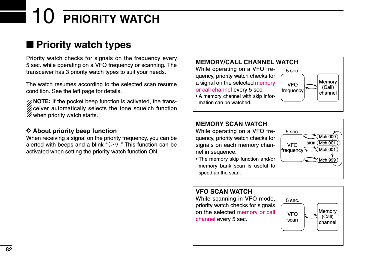
![■Priority watch operationDDMemory/call channel and memory scan watchqSelect VFO mode; then, set an operating frequency.wSet the watching channel(s).For memory channel watch:Select the desired memory channel.For call channel watch:Select the desired call channel.For memory scan watch:Select memory mode, or the desired bank group; then,push and hold [2/SCAN] for 1 sec. to start memory/bankscan.eEnter “PRIO WATCH” in scan set mode. (p. 00)rRotate [DIAL]†to select “ON.”• Select “BELL” if the priority beep function is necessary.tPush [VFO/MHz] to exit scan set mode and start thewatch.•“PRIO” indicator appears.•The transceiver checks the memory/bank channel(s) or callchannel every 5 sec.•The watch resumes according to the selected scan resume con-dition. (p. 00)yPush [VFO/MHz] to cancel the watch.¥ During priority watchMonitors VFO frequency for 5 sec.Pauses on a memory or call channel when a sig-nal is received.¥ During priority watch with priority beepEmits beep and blinks S indicator when a signal is re-ceived on a memory or call channel.PRIOPRIOFMFMA145180µ035035PRIOPRIOFMFMA433260PSKIPSKIPPRIOPRIOFMFMA145180µ035035PRIOPRIOFMFMA433260PSKIPSKIPMENU screen➪SCAN➪PRIO WATCH(Push [MENU/LOCK]) (Rotate [DIAL]†, then push [5/SKIP](ï)†.)Although [DIAL] and [5/SKIP](ï)are used for descriptionin this section, [2/SCAN](∫∫)/[8/TS](√√)and [6/M.N](≈≈)areavailable instead of [DIAL] and [5/SKIP](ï).8310PRIORITY WATCH12345678910111213141516171819†[DIAL] ↔[2/SCAN](∫∫)/[8/TS](√√) [5/SKIP](ï)↔[6/M.N](≈≈)](https://usermanual.wiki/ICOM-orporated/288800/User-Guide-649683-Page-89.png)
![8410 PRIORITY WATCHDDVFO scan watchqSet the watching channel(s).For memory channel watch:Select the desired memory channel.For call channel watch:Select the desired call channel.For memory scan watch:Select memory mode, or the desired bank group; then,push and hold [2/SCAN] for 1 sec. to start memory/bankscan.While scanning memory/bank channels:Starts memory/bank scan first. Memory/bank scan can-not be started after VFO scan is started.wEnter “PRIO WATCH” in scan set mode. (p. 00)eRotate [DIAL]†to select “ON.”• Select “BELL” if the priority beep function is necessary.rPush [VFO/MHz] to exit scan set mode and start thewatch.•“PRIO” indicator appears.tPush and hold [2/SCAN] for 1 sec. to enter scan type se-lection condition.yRotate [DIAL] to select the desired scan type from “ALL,”“BAND” and “PROG-xx (xx= 0–24),” “DUP.” uRelease [2/SCAN] to start the VFO scan watch.•The transceiver checks the memory/bank channel(s) or callchannel every 5 sec.•The watch resumes according to the selected scan resume con-dition. (p. 00)iPush [VFO/MHz] to cancel the watch.¥ During priority watchSearches VFO frequencies for 5 sec.Pauses on a memory or call channel when a sig-nal is received.¥ During priority watch with priority beepEmits beep and blinks S indicator when a signal is re-ceived on a memory or call channel.PRIOPRIOFMFMA145000µ000000PRIOPRIOFMFMA888800PSKIPSKIPPRIOPRIOFMFMA145000µ000000PRIOPRIOFMFMA888800PSKIPSKIPMENU screen➪SCAN➪PRIO WATCH(Push [MENU/LOCK]) (Rotate [DIAL]†, then push [5/SKIP](ï)†.)†[DIAL] ↔[2/SCAN](∫∫)/[8/TS](√√) [5/SKIP](ï)↔[6/M.N](≈≈)](https://usermanual.wiki/ICOM-orporated/288800/User-Guide-649683-Page-90.png)
![8511MENU SCREEN OPERATION12345678910111213141516171819■GeneralMENU screen is used for programming infrequently changedvalues or conditions of functions.DDEntering MENU screen and operatione.g.) Set “AUTO power OFF” to 30 minutes.qPush [MENU/LOCK] to enter MENU screen.wRotate [DIAL]†to select the desired menu group, thenpush [5/SKIP](ï)†.eRotate [DIAL]†to select the desired item, then push[5/SKIP](ï)†.rRotate [DIAL]†to select the desired value or condition,then push [5/SKIP](ï)†to return to the setting item selec-tion mode.tPush [MENU/LOCK] to return to frequency indication, re-peat steps wto rto set another items.[DIAL]OFFOFF30MIN30MIN60MIN60MIN90MIN90MIN120MIN120MINAUTO POWER OFFrOFFOFF30MIN30MIN60MIN60MIN90MIN90MIN120MIN120MINAUTO POWER OFFrAP OFFAP OFFPOWER SAVEPOWER SAVEATTENUATORATTENUATORMONITORMONITORDIAL SPEEDDIAL SPEEDSET MODEr• Setting itemsappear.SET MODESET MODESCANSCANDUP/TONE...DUP/TONE...DISPLAYDISPLAYSOUNDSSOUNDS***** MENU *****r• MENU groupsappear.†[DIAL] ↔[2/SCAN](∫∫)/[8/TS](√√) [5/SKIP](ï)↔[6/M.N](≈≈)](https://usermanual.wiki/ICOM-orporated/288800/User-Guide-649683-Page-91.png)
![8611 MENU SCREEN OPERATION■MENU screen indication forB band*While B band is selected, MENU screen shows following in-dication.select B band by pushing [BAND].*The optional UT-121 is required for IC-91A.■Menu list† Refer to the chapter 7 for details.■Items listDDSet modeAUTO POWER OFFPOWER SAVEATTENUATORMONITORDIAL SPEED-UPAUTO REPEATERMIC SIMPLE MODE ITEMSp. 103p. 103p. 103p. 103p. 103p. 103p. 103REF.AUTO POWER ONLOCKPTT LOCKBUSY LOCKOUTTIME-OUT TIMERACTIVE BAND ITEMSp. 103p. 103p. 103p. 103p. 103p. 103REF.pgs.103–103pgs.103–103pgs.103–103pgs.103–103pgs.103–103————pgs.103–103CALL SIGN†RX CALL SIGN†MESSAGE/POSITION†DV VOICE MEMO†SET MODEMENU REF.DV SET MODESCANDUP/TONE...DISPLAYSOUNDSMENU REF.RX CALL SRX CALL SMESSAGE/POSMESSAGE/POSDV VOICE MDV VOICE MSET MODESET MODEDV SET MODEDV SET MODE***** MENU ********** MENU *****rMENU screen indication for B band.](https://usermanual.wiki/ICOM-orporated/288800/User-Guide-649683-Page-92.png)
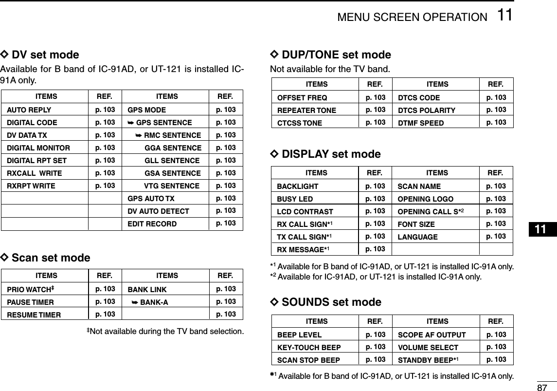
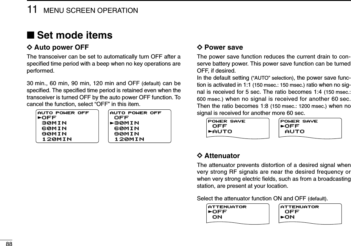
![8911MENU SCREEN OPERATION12345678910111213141516171819DDMonitor key actionThe monitor key, [SQL] , can be set as a ‘sticky’key. Whenset to the sticky condition, each push of [SQL] toggles themonitor function ON and OFF.•PUSH: Pushing and holding [SQL] to monitor the fre-quency. (default)•HOLD : Push [SQL] momentarily to monitor the frequencyand push momentarily again to cancel it.DDDial speed accelerationThe dial speed acceleration automatically speeds up the tun-ing dial speed when rotating [DIAL] rapidly.•OFF : The dial speed acceleration is turned OFF.•ON : The dial speed acceleration is tuned ON. (default)DDAuto repeaterThe auto repeater function automatically turns ON or OFF theduplex operation and tone encoder. The offset and repeatertone is not changed by the auto repeater function. Resetthese frequencies, if necessary.U.S.A. version:•OFF : The auto repeater function is turned OFF.•RPT1 : Activates for duplex only. (default)•RPT2 : Activates for duplex and tone.Korea version:•OFF : Deactivates the function.•ON : Activates duplex and tone. (default)ONONOFFOFFAUTO REPEATERrOFFOFFONONAUTO REPEATERrRPT1RPT1OFFOFFRPT2RPT2AUTO REPEATERrOFFOFFRPT1RPT1RPT2RPT2AUTO REPEATERrU.S.A./KOREAN versions onlyONONOFFOFFDIAL SPEED-UPrOFFOFFONONDIAL SPEED-UP rPUSHPUSHHOLDHOLDMONITORrHOLDHOLDPUSHPUSHMONITORr](https://usermanual.wiki/ICOM-orporated/288800/User-Guide-649683-Page-95.png)
![9011 MENU SCREEN OPERATIONDDMicrophone simple modeMicrophone simple mode is used to change the function as-signments for keys on the optional HM-75AREMOTE CONTROLSPEAKER-MICROPHONE. (p. ??)•SIMPLE•NORM-1 (default)•NORM-2DDWeather alert functionTurns weather alert function ON and OFF. (p.???)(default: OFF)DDAuto power ONAuto power ON function turns the transceiver power ON au-tomatically after passing the set time period from power OFF.Select the desired time period within 30 minutes to 24 hoursin 30 minutes steps and OFF. (default: OFF)DDKey lock TypeWhile the key lock function is ON, [PWR], [PTT], [SQL],[VOL] and [MENU](Lock function only) can still be accessed.Accessible keys can be set to 1 of 4 groups.•NORMAL : [PWR], [PTT], [SQL], [VOL] and [MENU](Lock function only) accessible. (default)•NO SQL : [PWR], [PTT], [SQL], and [MENU] (Lock func-tion only) are accessible.•NO VOL : [PWR], [PTT], [VOL], and [MENU] (Lock func-tion only) are accessible.•ALL : [PWR], [PTT] and [MENU] (Lock function only)are accessible.NORMALNORMALNO SQLNO SQLNO VOLNO VOLALLALLLOCKrNORMALNORMALNO SQLNO SQLNO VOLNO VOLALLALLLOCKrOFFOFFAUTO POWER ON24:0024:00AUTO POWER ONOFFOFFONONWEATHER ALERT WEATHER ALERT rOFFOFFONONWEATHER ALERT rU.S.A. version onlyNORM-1NORM-1SIMPLESIMPLENORM-2NORM-2MIC SIMPLE MODEMIC SIMPLE MODErSIMPLESIMPLENORM-1NORM-1NORM-2NORM-2MIC SIMPLE MODEr](https://usermanual.wiki/ICOM-orporated/288800/User-Guide-649683-Page-96.png)
![9111MENU SCREEN OPERATION12345678910111213141516171819DDPTT lock Turns the PTT lock function ON and OFF.Transmission with [PTT] is inhibited when ON is selected toprevent accidental transmission, etc. (default: OFF)DDBusy lockoutTurns the busy lockout function ON and OFF.This function inhibits transmission while receiving a signal orwhen the squelch is open. (default: OFF)DDTime-out timerTo prevent accidental prolonged transmission, etc., the trans-ceiver has a time-out timer. This function cuts a transmissionOFF after 1, 3, 5 or 10 min. of continuous transmission. Thistimer can be cancelled.•OFF : The time-out timer is turned OFF. (default)•1 to 10 MIN : The transmission is cut OFF after the setperiod elapses.DDActive bandAllows continuous frequency selection of the operating fre-quency across all bands.• SINGLE : The operating frequency can be selectedwithin the current band. Push [BAND] forband selection in this case.•ALL : The operating frequency can be selectedcontinuously. (default)ALLALLSINGLESINGLEACTIVE BAND rALLALLSINGLESINGLEACTIVE BANDrOFFOFF1MIN1MIN3MIN3MIN5MIN5MIN10MIN10MINTIME-OUT TIMERrOFFOFF1MIN1MIN3MIN3MIN5MIN5MIN10MIN10MINTIME-OUT TIMERrOFFOFFONONBUSY LOCKOUT rOFFOFFONONBUSY LOCKOUT rOFFOFFONONPTT LOCK rOFFOFFONONPTT LOCK r](https://usermanual.wiki/ICOM-orporated/288800/User-Guide-649683-Page-97.png)
![9211 MENU SCREEN OPERATION■DV set mode itemsThe following items are selectable by the IC-91AD or optionalUT-121 is installed into the IC-91A.DDAuto replyThis function replies to an individual station call even you areaway from the transceiver.After the manual transmission (pushing [PTT]), the AutoReply setting returns to OFF automatically.• OFF : No reply is performed even a call is received.(default)• ON : Sets caller’s call sign and reply to the call withthe set own call sign automatically.• VOICE : Sets caller’s call sign and reply to the call withthe recorded audio in REPLY VOICE memory ofDV VOICE MEMO.DDDigital codeSets the desired digital code for digital code squelch opera-tion. Total of 100 codes (00–99) are available. (default: 00)DDDV data TXDuring slow-speed data operation, auto data transmissionfunction is available. This function transmits when data hasbeen input from PC via the [DATA] jack. (default: PTT)DDDigital monitorSets the desired monitoring mode during digital mode opera-tion from “Auto,” “Digital” and “Analog.”• AUTO : The transceiver selects monitoring mode fromFM and DV according to the received signal.(default)• DIGITAL : Monitors in DV mode.• ANALOG : Monitors in FM mode.AUTOAUTODIGITALDIGITALANALOGANALOGDIGITAL MONITORrAUTOAUTODIGITALDIGITALANALOGANALOGDIGITAL MONITORrPTTPTTAUTOAUTODV DATA TXPTTPTTAUTOAUTODV DATA TXrr0000DIGITAL CODEDIGITAL CODE9999DIGITAL CODEOFFOFFONONVOICEVOICEAUTO REPLYAUTO REPLYrOFFOFFONONVOICEVOICEAUTO REPLYr](https://usermanual.wiki/ICOM-orporated/288800/User-Guide-649683-Page-98.png)
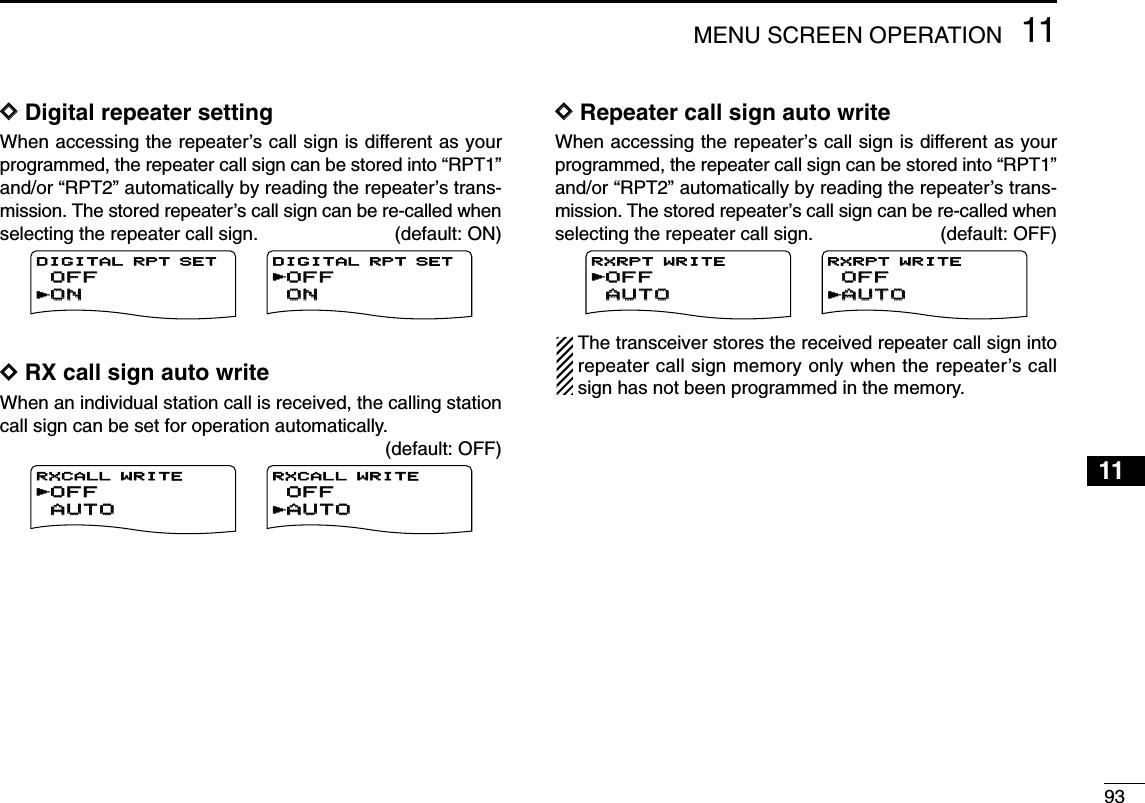
†toenter the sentence formatter setting condition.wRotate [DIAL]†to select the desired sentence formatterthat you want to change setting.•RMC, GGA, GLL, GSA and VTG are selectable.ePush [5/SKIP](ï)†to enter the desired sentence formattersetting condition.rRotate [DIAL]†to select the setting. tRotate [DIAL]†to select next sentence and repeat stepswto r, or push [MENU/LOCK] to return to frequency in-dication.•Only three sentence formatters are activated at same time.OFFOFFONONRMC SENTENCErOFFOFFONONRMC SENTENCErRMC:OFFRMC:OFFGGA:ONGGA:ONGLL:OFFGLL:OFFGSA:OFFGSA:OFFVTG:OFFVTG:OFFGPS SENTENCErRMC:OFFRMC:OFFGGA:ONGGA:ONGLL:OFFGLL:OFFGSA:OFFGSA:OFFVTG:OFFVTG:OFFGPS SENTENCErOFFOFFONON:SENTENCEGPS MODEr:SENTENCEOFFOFFONONGPS MODEr](https://usermanual.wiki/ICOM-orporated/288800/User-Guide-649683-Page-100.png)
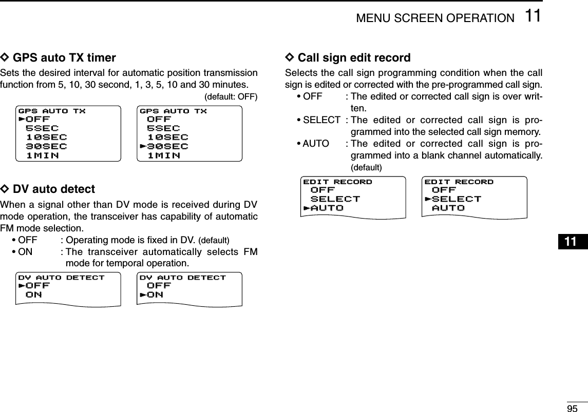
![9611 MENU SCREEN OPERATION■Scan set mode itemsDDPriority watchActivates priority watch or priority watch with alert (Bell).•OFF : The priority watch is turned OFF. (default)•ON : The transceiver checks the memory channel fre-quency every 5 sec.•BELL : The transceiver checks the memory channel fre-quency every 5 sec. You can be alerted withbeeps and blinking “S”.DDScan pause timerSelects the scan pause time. When receiving signals, thescan pauses according to the scan pause time.•2–20 SEC : Scan pauses for 2–20 sec. on a receivedsignal in 2 sec. steps. (default: 10 sec.)•HOLD : Scan pauses on a received signal until it dis-appears. Rotate [DIAL] to resume manually.DDScan resume timerSelects the scan resume time of a paused frequency after thereceived signal disappears.•0 : Scan resumes when a received signal disap-pears.•1–5 SEC : Scan pause 1–5 sec. after a received signaldisappears. (default: 2 sec.)•HOLD : Scan pauses on the received signal even if itdisappears. Rotate [DIAL]†to resume manu-ally.Scan resume timer must be set shorter than scan pausetimer (previous item), otherwise this timer does not activate.2SEC2SEC4SEC4SEC3SEC3SEC1SEC1SEC5SEC5SECRESUME TIMERr3SEC3SEC5SEC5SEC4SEC4SEC2SEC2SECHOLDHOLDRESUME TIMERr10SEC10SEC6SEC6SEC8SEC8SEC4SEC4SEC12SEC12SECPAUSE TIMERr20SEC20SEC16SEC16SEC18SEC18SEC14SEC14SECHOLDHOLDPAUSE TIMERrOFFOFFONONBELLBELLPRIO WATCHPRIO WATCHrOFFOFFONONBELLBELLPRIO WATCHr](https://usermanual.wiki/ICOM-orporated/288800/User-Guide-649683-Page-102.png)
![9711MENU SCREEN OPERATION12345678910111213141516171819DDMemory bank link functionSets the memory bank link function ON (default) and OFF. Thelink function provides continuous bank scan, scanning all con-tents in the selected banks during bank scan.•Bank link settingqRotate [DIAL]†to select the bank that you want to changesetting.wPush [5/SKIP](ï)†to enter the bank setting condition.eRotate [DIAL]†to select the setting. rPush [5/SKIP](ï)†to set and return to the BANK LINKscreen.tRotate [DIAL]† to select next bank and repeat steps wtor, or push [MENU/LOCK] to exit scan set mode.■DUP/TONE set mode itemsDDOffset frequencySets the offset frequency for duplex (repeater) operation within0 to 159.995 MHz range.The default value may differ according to the selected fre-quency band (before accessing DUP/TONE set mode) and trans-ceiver version.The selected tuning step in VFO mode is used for settingthe offset frequency.DDRepeater tone frequencySelects subaudible tone frequency for accessing a repeater,etc. Total of 50 tone frequencies (67.0–254.1 Hz) are available.(default: 88.5) 88.5 88.5REPEATER TONE254.1254.1REPEATER TONE 0.000.00 0.000.00OFFSET FREQ159.995.00159.995.00OFFSET FREQONONOFFOFFBANK-ABANK-ArONONOFFOFFBANK-ArBANK-A:ONBANK-A:ONBANK-D:ONBANK-D:ONBANK-C:ONBANK-C:ONBANK-B:ONBANK-B:ONBANK-E:ONBANK-E:ONBANK LINKBANK LINKrBANK-V:ONBANK-V:ONBANK-Y:ONBANK-Y:ONBANK-X:ONBANK-X:ONBANK-W:ONBANK-W:ONBANK-Z:ONBANK-Z:ONBANK LINK\r](https://usermanual.wiki/ICOM-orporated/288800/User-Guide-649683-Page-103.png)
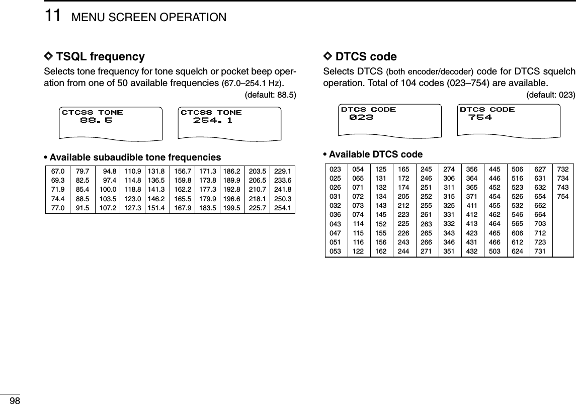
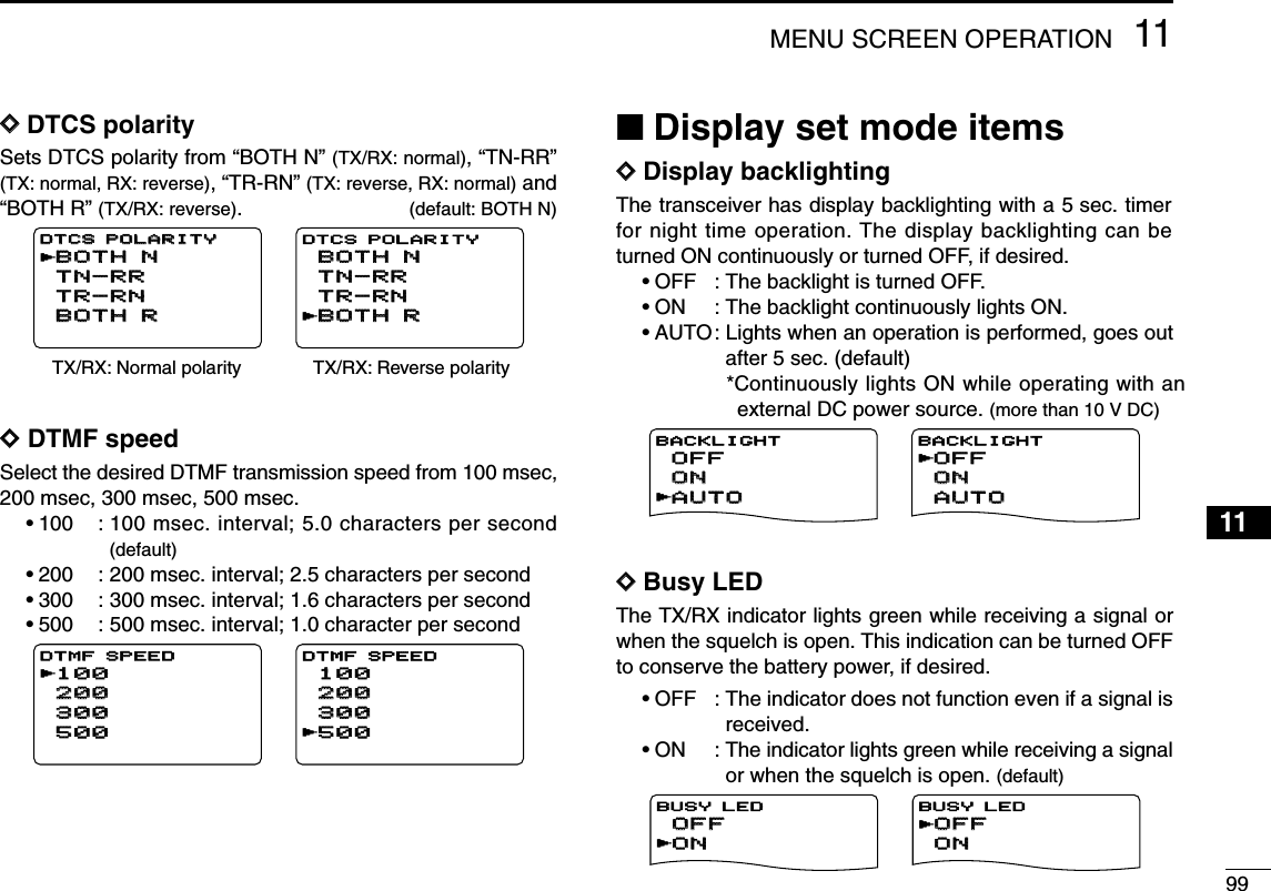
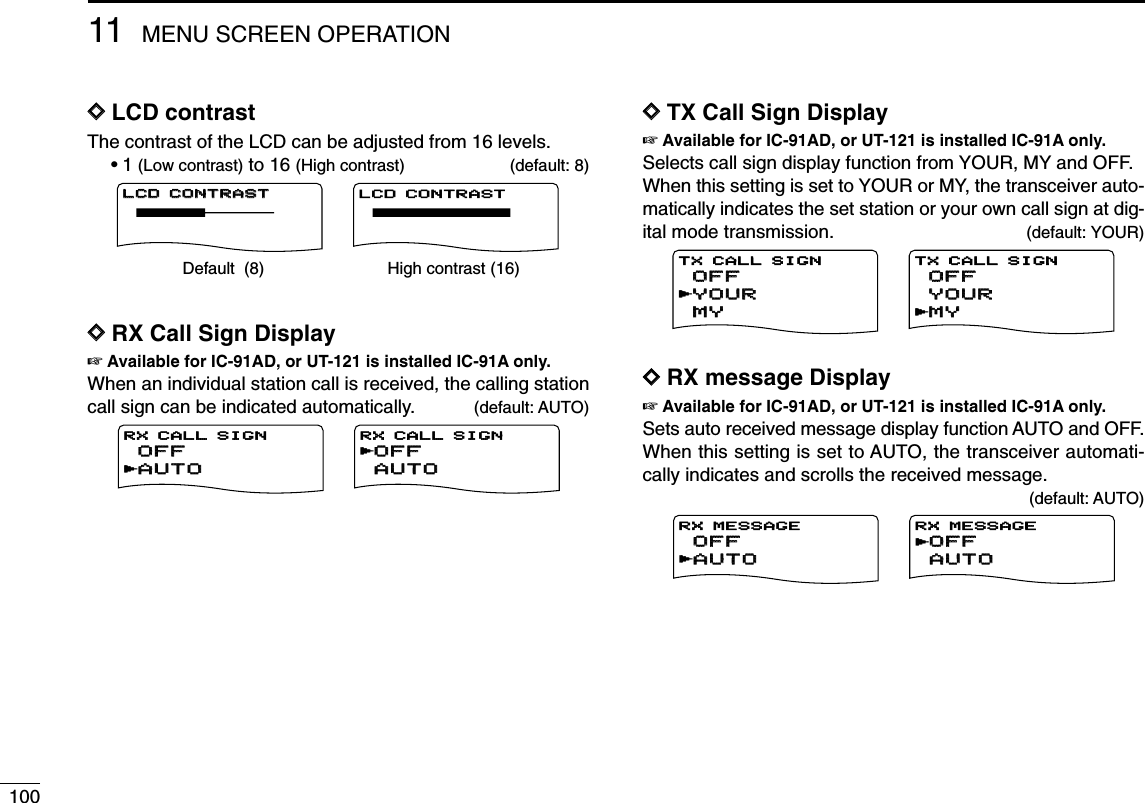
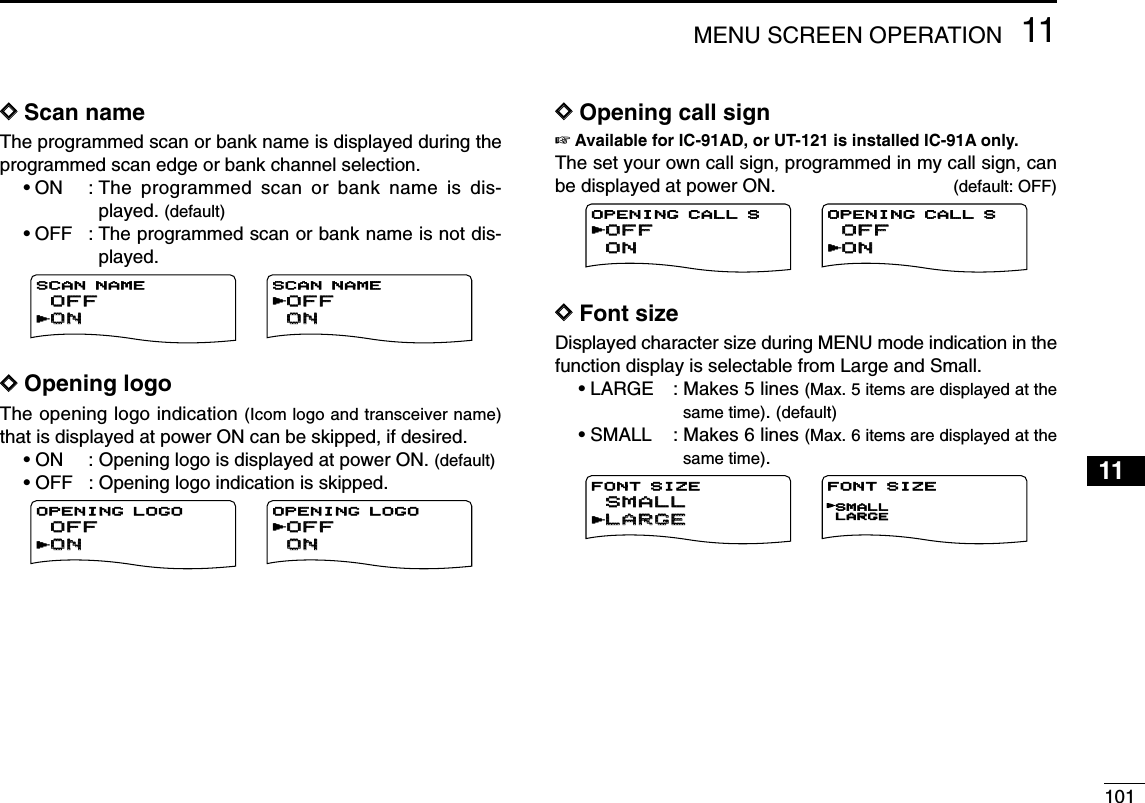
![10211 MENU SCREEN OPERATION■Sounds set mode itemsDDBeep output levelAdjusts the key-touch beep tone level to the desired levelwithin 39 levels.The key-touch beep (below item) must be set to ON to havea beep tone.DDKey-touch beepTurns the key-touch beep ON or OFF. (default: ON)DDScan stop beepTurns the scan stop beep function ON or OFF. (default: OFF) DDScope audio outputSelect the audio output function capability during sweep withband scope function.•ON : The received audio sounds during sweep. (de-fault)•OFF : No audio sounds during sweep.DDVolume selectSelect the volume level adjustment from Both and Separate.•BOTH : Both A and B bands volume level is ad-justed with [VOL] at the same time.(default)•SEPARATE : The Volume setting is adjusted indepen-dently in A and B bands with [VOL].BOTHBOTHSEPARATESEPARATEVOLUME SELECTrSEPARATESEPARATEBOTHBOTHVOLUME SELECTrONONOFFOFFSCOPE AF OUTPUTrOFFOFFONONSCOPE AF OUTPUTrOFFOFFONONSCAN STOP BEEPrONONOFFOFFSCAN STOP BEEPrONONOFFOFFKEY-TOUCH BEEPrOFFOFFONONKEY-TOUCH BEEPrBEEP LEVELBEEP LEVEL BEEP LEVELMinimum level (no audio) Maximum level](https://usermanual.wiki/ICOM-orporated/288800/User-Guide-649683-Page-108.png)
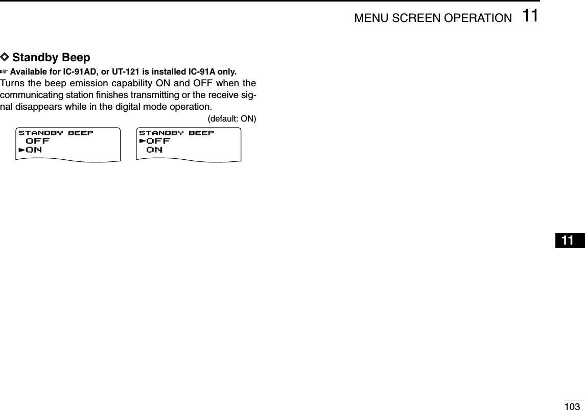
 for 1 sec. to enterDTMF memory.wRotate [DIAL]†to select the desired DTMF memory chan-nel.•“T-CALL” appears when a 1750 Hz tone burst signal is selected.(p. ??)ePush and hold [6/M.N](≈≈)for 1 sec. to enter programmingmode.•Previously programmed DTMF code is cleared.rPush the desired keys to input the characters.•[VFO/MHz](A) inputs “A,”[MR/S.MW](B) inputs “B,”[CALL/RX➝CS](C) inputs “C,”[BAND](D) inputs “D,”[./EMR/DTMF.M](#) inputs “#” and [REC/MODE](✱)inputs “✱”.•Up to 16 digits can be programmed.•Push [MAIN/DUAL] to delete the cursor placed code.•Push and hold [MAIN/DUAL] for 1 sec. to delete the cursorplaced or later codes.tRepeat step runtil the desired code is input.yPush [MENU/LOCK] to program the DTMF code and exitprogramming mode.•Entering 16th digit automatically exits the programming mode.rCh01DTMF MEMORYrCh016DTMF MEMORYCh01Ch01 01234567 01234567 89ABC*#0 89ABC*#0:SET:BACK:SEL:EDITDTMF MEMORYrCh01Ch01 01234567 01234567 89AB 89AB6SQL:SET MAIN:CLR SQL:SET MAIN:CLRDTMF MEMORYrCh01Ch01 012345 01234567 89AB 89ABDTMF MEMORYrrCh01DTMF MEMORYrCh01Ch016DTMF MEMORYCh01 01234567 89ABC*#0:SET:BACK:SEL:EDITDTMF MEMORYCh01 01234567 89AB6SQL:SET MAIN:CLR SQL:SET MAIN:CLRDTMF MEMORYCh01 01234567 89ABDTMF MEMORYrCh01Ch01DTMF MEMORYrCh016DTMF MEMORYCh01 01234567 89ABC*#0:SET:BACK:SEL:EDITDTMF MEMORYCh01 01234567 89AB6SQL:SET MAIN:CLR SQL:SET MAIN:CLRDTMF MEMORYCh01 01234567 89ABDTMF MEMORY](https://usermanual.wiki/ICOM-orporated/288800/User-Guide-649683-Page-110.png)
![10512OTHER FUNCTIONS12345678910111213141516171819■Transmitting a DTMF codeDTransmitting from DTMF memoryThe selected DTMF code is transmitted at each push of the[SQL] switch while transmitting.The transmitting speed at which DTMF memories send in-dividual DTMF characters can be set in “DTMF SPEED”menu. (p. ??)qSet the desired frequency. (p. ??)wPush and hold [./EMR/DTMF.M](#) for 1 sec. to enterDTMF memory.eRotate [DIAL]†to select the desired DTMF memory chan-nel.rPush [VFO/MHz] to exit DTMF memory.tWhile pushing [PTT], push [SQL] to transmit the selectedDTMF code.DTransmitting a DTMF code directlyDTMF code can be transmitted via keypad directly whiletransmitting.qSet the desired frequency. (p. ??)wWhile pushing [PTT], push the desired keys to transmit theDTMF code.•[0/CQ]–[9/BK/T.SCAN] input “0”–“9,” [VFO/MHz](A) inputs “A,”[MR/S.MW](B) inputs “B,”[CALL/RX➝CS](C) inputs “C,”[BAND](D) inputs “D,” [./EMR/DTMF.M](#) inputs “#” and[REC/MODE](✱)inputs “✱.”MemoNamePRIO WX EMRDTCSFMA438500PSKIP+DUP25µ0005D28AB4AFM438500PSKIPMemoNamePRIOPRIO WXWX EMREMRDTCSDTCSFMFMA438500PSKIPPSKIP+DUP+DUP25µ0005D28AB45D28AB4AFM438500P SKIP†[DIAL] ↔[2/SCAN](∫∫)/[8/TS](√√) [5/SKIP](ï)↔[6/M.N](≈≈)](https://usermanual.wiki/ICOM-orporated/288800/User-Guide-649683-Page-111.png)
 for 1 sec. to enterDTMF memory mode.wRotate [DIAL]†to select the desired DTMF memory chan-nel to be cleared.ePush [6/M.N](≈≈)to enter programming mode, and rotate[DIAL] to set cursor to 1st digit.rPush and hold [MAIN/DUAL] for 1 sec. to clear the se-lected DTMF memory channel.•The DTMF memory channel is cleared.tPush [MENU/LOCK] to exit programming mode.■Confirming a DTMF memoryThe DTMF memory can be confirmed with a DTMF tone.qPush and hold [./EMR/DTMF.M](#) for 1 sec. to enterDTMF memory mode.wRotate [DIAL]†to select the desired DTMF memory chan-nel.ePush [SQL] to confirm the DTMF memory contents.Push [SQL], then sounds DTMF codes.Ch01 61234567 89ABSQL:BACK MAIN:CLRDTMF MEMORYCh01 6SQL:BACK MAIN:CLRDTMF MEMORY[DIAL]Ch01Ch01 01234567 01234567 89ABC*#0 89ABC*#0:SET:BACK:SEL:EDITDTMF MEMORYr[DIAL] ••The cursor is blinking.The cursor is blinking.When entering DTMF programming mode.After clearing the DTMF memory.Ch01Ch01 612345671234567 89AB 89ABSQL:BACKSQL:BACK MAIN:CLRMAIN:CLRDTMF MEMORYrCh01Ch01 6SQL:BACKSQL:BACK MAIN:CLRMAIN:CLRDTMF MEMORYrCh01 01234567 89ABC*#0:SET:BACK:SEL:EDITDTMF MEMORY](https://usermanual.wiki/ICOM-orporated/288800/User-Guide-649683-Page-112.png)
![10712OTHER FUNCTIONS12345678910111213141516171819■Setting DTMF transferringspeedThe DTMF transferring speed can be selected.qEnter “DTMF SPEED” in DUP/TONE... set mode. (p. ??)wRotate [DIAL]†to select DTMF transferring speed asbelow.100: Transfer the DTMF data per about 100 msec.200: Transfer the DTMF data per about 200 msec.300: Transfer the DTMF data per about 300 msec.500: Transfer the DTMF data per about 500 msec.ePush [5/SKIP](ï)to set DTMF transferring speed andpush [MENU/LOCK] to return to frequency indication.■Tone frequency and DTCScodeDSubaudible (repeater) toneSome repeaters require subaudible tones to be accessed.Subaudible tones are superimposed over your normal signaland must be set in advance.DTone and DTCS squelchesThe tone squelch (CTCSS) or DTCS squelch opens onlywhen receiving a signal containing a matching subaudibletone or DTCS code, respectively. You can silently wait forcalls from group members using the same tone or code. Sep-arate tone frequencies can be set for repeater and tonesquelch/pocket beep operation.DPocket beepThese functions use subaudible tones or DTCS codes forcalling and can be used as a “common pager” to inform youthat someone has called while you were away from the trans-ceiver. The same code is used for DTCS squelch and beep.MENU screen➪DUP/TONE...➪DTMF SPEED(Push [MENU/LOCK]) (Rotate [DIAL]†, then push [5/SKIP](ï)†.) DV SET MODE SCANrDUP/TONE...***** MENU *****r100100 200200 500500 300300DTMF SPEED†[DIAL] ↔[2/SCAN](∫∫)/[8/TS](√√) [5/SKIP](ï)↔[6/M.N](≈≈)](https://usermanual.wiki/ICOM-orporated/288800/User-Guide-649683-Page-113.png)
![10812 OTHER FUNCTIONS■TONE FREQUENCY AND DTCS CODE (Continued)DSetting subaudible tones for repeater or tonesquelchqEnter “CTCSS TONE” in DUP/TONE… (or RPT TONE) setmode. (p. ??)wRotate [DIAL]†to select the desired repeater or CTCSStone frequency.•Each operating band and each memory channel have indepen-dent settings.ePush [5/SKIP](ï)to set repeater or CTCSS tone fre-quency and push [MENU/LOCK] to return to frequency in-dication.DSetting DTCS code for DTCS squelch orbeepqEnter “DTCS TONE” in DUP/TONE... set mode. (p. ??)wRotate [DIAL]†to select the desired DTCS tone code.•Each operating band and each memory channel have indepen-dent settings.ePush [5/SKIP](ï)to set DTCS tone code and push[MENU/LOCK] to return to frequency indication.DTCS phase mode can be selected in “DTCS POLARITY”menu. (p. ??) DV SET MODE SCANrDUP/TONE...***** MENU ***** 88.5 200 500r300CTCSS TONE 88.5 200 500r300REPEATER TONE DV SET MODE SCANrDUP/TONE...***** MENU ***** 023023 200200 500500r300300DTCS TONEMENU screen➪DUP/TONE...➪DTCS TONE(Push [MENU/LOCK]) (Rotate [DIAL]†, then push [5/SKIP](ï)†.) DV SET MODE SCANrDUP/TONE...***** MENU ***** 88.588.5 200200 500500r300300CTCSS TONECTCSS TONE 88.588.5 200200 500500r300300REPEATER TONE DV SET MODE SCANrDUP/TONE...***** MENU ***** 023 200 500r300DTCS TONEMENU screen➪DUP/TONE...➪CTCSS TONE(Push [MENU/LOCK]) (Rotate [DIAL]†, then push [5/SKIP](ï)†.)](https://usermanual.wiki/ICOM-orporated/288800/User-Guide-649683-Page-114.png)
![10912OTHER FUNCTIONS12345678910111213141516171819DSetting digital code for digital code squelchor beepqPush [MAIN/DUAL] to select B band, then push and hold[REC/MODE] for 1 sec. several times to select DV mode.wEnter “DIGITAL CODE” in DV SET MODE.(p. ??)eRotate [DIAL]†to select the desired digital code.•Each operating band and each memory channel have indepen-dent settings.rPush [5/SKIP](ï)to set digital code and push[MENU/LOCK] to return to frequency indication.DSetting the your and my call signs for callsign squelch or beepqPush [MAIN/DUAL] to select B band, then and hold[REC/MODE] for 1 sec. several times to select DV mode.wEnter “YOUR CALL SIGN” in CALL SIGN set mode. (p. ??)eRotate [DIAL]†to select the desired call sign.•Input the call sign if the desired call sign is not registered in thetransceiver. See p. ?? for detail.rPush [5/SKIP](ï)to set call sign and return to “CALLSIGN” in menu screen.Continue to the next page. DV VOICE M SET MODErDV SET MODE***** MENU ***** 00 200 500r300DIGITAL CODErCALL SIGN RX CALL S MESSAGE/POS***** MENU *****rU01U01 ABCDEFABCDEF 500500r300300YOUR CALL SIGNrM01 GHIJKL 500r300MY CALL SIGNMENU screen➪CALL SIGN➪YOUR CALL SIGN(Push [MENU/LOCK]) (Rotate [DIAL]†, then push [5/SKIP](ï)†.) DV VOICE M SET MODErDV SET MODE***** MENU ***** 0000 200200 500500r300300DIGITAL CODErCALL SIGN RX CALL S MESSAGE/POS***** MENU *****rU01 ABCDEF 500r300YOUR CALL SIGNrM01 GHIJKL 500r300MY CALL SIGNMENU screen➪DV SET MODE➪DIGITAL CODE(Push [MENU/LOCK]) (Rotate [DIAL]†, then push [5/SKIP](ï)†.)■Digital code and call sign setting The optional UT-121 is required for IC-91A†[DIAL] ↔[2/SCAN](∫∫)/[8/TS](√√) [5/SKIP](ï)↔[6/M.N](≈≈)](https://usermanual.wiki/ICOM-orporated/288800/User-Guide-649683-Page-115.png)
![11012 OTHER FUNCTIONSDSetting the your and my call signs for call sign squelch orbeep (Continued)tRotate [DIAL]†to select “MY CALL SIGN” in CALL SIGNset mode, then push [5/SKIP](ï)†to enter “MY CALLSIGN” setting.yRotate [DIAL]†to select the desired call sign.•Input the call sign if the desired call sign is not registered in thetransceiver. See p. ?? for detail.uPush [5/SKIP](ï)†to set call sign and push[MENU/LOCK] to return to frequency indication.CAUTION!: Use digital code squelch function when operat-ing with more than 3 stations. Because the digital call signsquelch function recognizes “MY CALL SIGN”. Therefore,the digital call sign squelch function can be used when op-erating with only one station.NOTE:• The tone/DTCS code squelch opens sometimes whenother stations communicate with adjacent tone frequencyor DTCS code.• Sounds no audio with S-meter swing when receiving a sig-nal which is not included in “MY CALL SIGN” on DVmode. DV VOICE M SET MODErDV SET MODE***** MENU ***** 00 200 500r300DIGITAL CODErCALL SIGN RX CALL S MESSAGE/POS***** MENU *****rU01 ABCDEF 500r300YOUR CALL SIGNrM01M01 GHIJKLGHIJKL 500500r300300MY CALL SIGNMENU screen➪CALL SIGN➪MY CALL SIGN(Push [MENU/LOCK]) (Rotate [DIAL]†, then push [5/SKIP](ï)†.)†[DIAL] ↔[2/SCAN](∫∫)/[8/TS](√√) [5/SKIP](ï)↔[6/M.N](≈≈)](https://usermanual.wiki/ICOM-orporated/288800/User-Guide-649683-Page-116.png)
![11112OTHER FUNCTIONS12345678910111213141516171819■Tone/DTCS squelchqSet the desired operating frequency, CTCSS tone andDTCS code.wPush and hold [7/DSQ/TONE] for 1 sec. several times toactivate the tone or DTCS squelch. (TONE, TSQL orDTCS)•Subaudible tone encoder “TONE,” tone squelch “TSQL,” pocketbeep “TSQLS,” DTCS squelch “DTCS,” DTCS beep“DTCSS” and no tone operation are activated in order.•Rotating [DIAL] while pushing [7/DSQ/TONE] also selects thetone functions.eOperate the transceiver in the normal way.rWhen the received signal includes a matching tone/code,the squelch opens and the signal can be heard.•When the received signal’s tone/code does not match,tone/DTCS squelch does not open, however, the S-indicatorshows signal strength.•To open the squelch manually, push and hold [SQL].■Digital code/digital call signsquelch qSet the desired operating frequency on DV mode, Digitalcode and my call sign.wPush and hold [7/DSQ/TONE] for 1 sec. several times toactivate the digital code or digita call signl squelch. (DSQLor CSQL)•Digital call sign squelch “DSQL,” Digital call sign beep“DSQLS”, Digital code squelch “CSQL,” Digital code beep“CSQLS” and no tone operation are activated in order.•Rotating [DIAL] while pushing [7/DSQ/TONE] also selects thetone functions.eOperate the transceiver in the normal way.rWhen the received signal includes a matching callsign/code, the squelch opens and the signal can be heard.•When the received signal’s call sign/code does not match, digitalcall sign/digital code squelch does not open, however, the S-in-dicator shows signal strength.•To open the squelch manually, push and hold [SQL].BMemoNamePRIO WX EMRDTCSFM145300PSKIP+DUP25BMemoNamePRIO WX EMRTONEFM145300PSKIP+DUP25BMemoNamePRIO WX EMRTSQLFM145300PSKIP+DUP25BMemoNamePRIO WX EMRDTCSFM145300PSKIP+DUP25BMemoNamePRIO WX EMRTSQLFM438500PSKIP+DUP25BMemoNamePRIO WX EMRDTCSFM438500PSKIP+DUP25BMemoNamePRIO WX EMRDTCSFM145300PSKIP+DUP25BMemoNamePRIO WX EMRTSQLFM145300PSKIP+DUP25BMemoNameMemoNamePRIOPRIO WXWX EMREMRDSQLDSQLDVDV145300PSKIPPSKIP+DUP+DUP2525BMemoNameMemoNamePRIOPRIO WXWX EMREMRCSQLCSQLDVDV145300PSKIPPSKIP+DUP+DUP2525BMemoNameMemoNamePRIOPRIO WXWX EMREMRDSQLDSQLDVDV145300PSKIPPSKIP+DUP+DUP2525BMemoNameMemoNamePRIOPRIO WXWX EMREMRCSQLCSQLDVDV145300PSKIPPSKIP+DUP+DUP2525BMemoNamePRIO WX EMRDSQLDV438500PSKIP+DUP25BMemoNamePRIO WX EMRCSQLDV438500PSKIP+DUP25The optional UT-121 is required for IC-91ABMemoNameMemoNamePRIOPRIO WXWX EMREMRDTCSDTCSFMFM145300PSKIPPSKIP+DUP+DUP2525BMemoNameMemoNamePRIOPRIO WXWX EMREMRTONETONEFMFM145300PSKIPPSKIP+DUP+DUP2525BMemoNameMemoNamePRIOPRIO WXWX EMREMRTSQLTSQLFMFM145300PSKIPPSKIP+DUP+DUP2525BMemoNameMemoNamePRIOPRIO WXWX EMREMRDTCSDTCSFMFM145300PSKIPPSKIP+DUP+DUP2525BMemoNamePRIO WX EMRTSQLFM438500PSKIP+DUP25BMemoNamePRIO WX EMRDTCSFM438500PSKIP+DUP25BMemoNameMemoNamePRIOPRIO WXWX EMREMRDTCSDTCSFMFM145300PSKIPPSKIP+DUP+DUP2525BMemoNameMemoNamePRIOPRIO WXWX EMREMRTSQLTSQLFMFM145300PSKIPPSKIP+DUP+DUP2525BMemoNamePRIO WX EMRDSQLDV145300PSKIP+DUP25BMemoNamePRIO WX EMRCSQLDV145300PSKIP+DUP25BMemoNamePRIO WX EMRDSQLDV145300PSKIP+DUP25BMemoNamePRIO WX EMRCSQLDV145300PSKIP+DUP25BMemoNamePRIO WX EMRDSQLDV438500PSKIP+DUP25BMemoNamePRIO WX EMRCSQLDV438500PSKIP+DUP25](https://usermanual.wiki/ICOM-orporated/288800/User-Guide-649683-Page-117.png)
![11212 OTHER FUNCTIONS■Pocket beep functionqSet the desired operating frequency.wSet the desired CTCSS tone, DTCS code, Digital call signor Digital code.ePush and hold [7/DSQ/TONE] for 1 sec. several times toactivate the pocket beep, DTCS beep, Digital call signbeep or Digital code beep. (TSQLS, DTCS S,DSQLSor CSQLS)•Rotating [DIAL] while pushing [7/DSQ/TONE] also selects thetone functions.rWhen a signal with the correct tone, code, digital call signor digital code is received, the transceiver emits beeptones for 30 sec. and blinks “S.”tPush [PTT] to answer or push [SQL] to stop the beepsand blinking.■DTCS polarity settingqEnter “DTCS P” in DUP/TONE... set mode. (p. ??)wRotate [DIAL]†to select the desired DTCS porarity mode.• BOTH H: Normal pahses are used for both TX andRX. (Default)• TN-RR: Normal pahse is used for TX; Reversephase for RX.• TR-RN: Reverse pahse is used for TX; Normalphase for RX.• BOTH R: Reverse pahses are used for both TX andRX.ePush [5/SKIP](ï)to set repeater or CTCSS tone fre-quency and push [MENU/LOCK] to return to frequency in-dication.rRPT TONERPT TONE CTCSS TONECTCSS TONErDTCS CODEDTCS CODEDUP/TONE...rDTCS PDTCS PMENU screen➪DUP/TONE...➪DTCS P(Push [MENU/LOCK]) (Rotate [DIAL]†, then push [5/SKIP](ï)†.)BMemoNamePRIO WX EMRDTCSFM145300PSKIP+DUP25BMemoNamePRIO WX EMRTONEFM145300PSKIP+DUP25BMemoNamePRIO WX EMRTSQLFM145300PSKIP+DUP25BMemoNamePRIO WX EMRDTCSFM145300PSKIP+DUP25BMemoNameMemoNamePRIOPRIO WXWX EMREMRTSQLTSQLFMFM438500PSKIPPSKIP+DUP+DUP2525BMemoNameMemoNamePRIOPRIO WXWX EMREMRDTCSDTCSFMFM438500PSKIPPSKIP+DUP+DUP2525BMemoNamePRIO WX EMRDTCSFM145300PSKIP+DUP25BMemoNamePRIO WX EMRTSQLFM145300PSKIP+DUP25BMemoNamePRIO WX EMRDSQLDV145300PSKIP+DUP25BMemoNamePRIO WX EMRCSQLDV145300PSKIP+DUP25BMemoNamePRIO WX EMRDSQLDV145300PSKIP+DUP25BMemoNamePRIO WX EMRCSQLDV145300PSKIP+DUP25BMemoNameMemoNamePRIOPRIO WXWX EMREMRDSQLDSQLDVDV438500PSKIPPSKIP+DUP+DUP2525BMemoNameMemoNamePRIOPRIO WXWX EMREMRCSQLCSQLDVDV438500PSKIPPSKIP+DUP+DUP2525†[DIAL] ↔[2/SCAN](∫∫)/[8/TS](√√) [5/SKIP](ï)↔[6/M.N](≈≈)](https://usermanual.wiki/ICOM-orporated/288800/User-Guide-649683-Page-118.png)
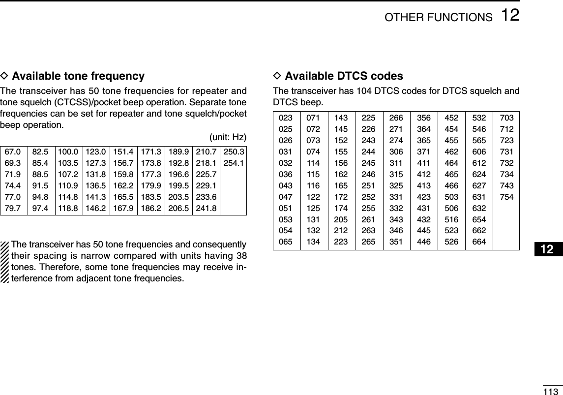
![11412 OTHER FUNCTIONS■Tone scanThe transceiver can detect the subaudible tone frequency andDTCS code in a received signal. By monitoring a signal thatis being transmitted on a repeater input frequency, you candetermine the tone frequency required to access the repeater.qSet the desired frequency or memory channel to bechecked for a tone frequency or DTCS code.wPush and hold [7/DSQ/TONE] for 1 sec. several times toactivate the repeater tone, tone squelch or DTCS squelch.(TONE, TSQL or DTCS)•Rotating [DIAL] while pushing and holding [7/DSQ/TONE] alsoselects the tone functions.ePush and hold [9/BK/T.SCAN] for 1 sec. to start the tonescan.•To change the scanning direction, rotate [DIAL].rWhen the tone frequency or DTCS code is decoded, theset mode contents are programmed with the frequency orcode.•The tone scan pauses approx. 10 sec. when a tone frequencyor DTCS code is detected.•The decoded tone frequency is used for the repeater tone fre-quency when the tone squelch is OFF.•The decoded tone frequency is used for the tone squelch fre-quency when the tone squelch is ON.•The decoded DTCS code is used for the DTCS code when theDTCS squelch is ON.tPush [VFO/MHz] to stop the scan.•If the scan is cancelled before the transceiver detects the tone orcode, the set mode contents are not changed.AMemoNameMemoNamePRIOPRIO WXWX EMREMRDTCSDTCSFMFM1713PSKIPPSKIP+DUP+DUP2525AMemoNameMemoNamePRIOPRIO WXWX EMREMRDTCSDTCSDVDV662PSKIPPSKIP+DUP+DUP2525](https://usermanual.wiki/ICOM-orporated/288800/User-Guide-649683-Page-120.png)
![11512OTHER FUNCTIONS12345678910111213141516171819■Beep tonesYou can select to have confirmation beeps sound at the pushof a switch. The output level can be adjusted within 39 levelsor to the related level of the volume in BEEP LEVEL setmode. (p. ??)You can select silent operation by turning beep tones OFF inKEY-TOUCH B set mode. (p. ??)■Dial speed accelerationThe dial speed acceleration automatically speeds up the tun-ing dial speed when rotating [DIAL] rapidly.This function can be turned ON and OFF in DIAL SPEED setmode. (p. ??)■Key lock effectDLock functionThe lock function prevents accidental frequency changes andaccidental function access.➥Push [MENU/LOCK] for 1 sec. to toggle the lock functionON and OFF.•[PWR], [VOL], [SQL] and [PTT] can still be accessed while thelock function is ON. (default)DKey lock typeWhile the lock function is ON, [PWR], [VOL], [SQL] and[PTT] can still be accessed. Accessible switches can be setto one of 4 groups in LOCK set mode. (p. ??)•“NORMAL”: [PWR], [VOL], [SQL] and [PTT] are accessible.•“NO SQL”: [PWR], [SQL] and [PTT] are accessible.•“NO VOL”: [PWR], [VOL] and [PTT] are accessible.•“ALL”: [PWR] and [PTT] are accessible.MENU screen➪SET MODE➪LOCK(Push [MENU/LOCK]) (Rotate [DIAL]†, then push [5/SKIP](ï)†.)AFMFM439540PSKIPSKIPMENU screen➪SET MODE➪DIAL SPEED(Push [MENU/LOCK]) (Rotate [DIAL]†, then push [5/SKIP](ï)†.)MENU screen➪SOUNDS➪KEY-TOUCH B(Push [MENU/LOCK]) (Rotate [DIAL]†, then push [5/SKIP](ï)†.)MENU screen➪SOUNDS➪BEEP LEVEL(Push [MENU/LOCK]) (Rotate [DIAL]†, then push [5/SKIP](ï)†.)†[DIAL] ↔[2/SCAN](∫∫)/[8/TS](√√) [5/SKIP](ï)↔[6/M.N](≈≈)](https://usermanual.wiki/ICOM-orporated/288800/User-Guide-649683-Page-121.png)
 several times to select weatherchannel mode.•“WX” and the weather channel number appear.wRotate [DIAL] to select the desired weather channel.ePush [VFO/MHz] or [MR/S.MW] to return to the previousfrequency or memory channel.DDWeather alert functionNOAA broadcast stations transmit weather alert tones beforeimportant weather announcements. When the weather alertfunction is turned ON, the selected weather channel is moni-tored every 5 sec. for the announcement. When the alert sig-nal is detected, the “ALT” and the WX channel are displayedalternately and sounds a beep tone until the transceiver is op-erated. The previously selected (used) weather channel ischecked periodically during standby or while scanning.qSelect the desired weather channel.wEnter “WEATHER ALERT” in set mode.(p. ??)eRotate [DIAL]†to select “ON” or “OFF.”rPush [5/SKIP](ï)to set the weather alert function andpush [MENU/LOCK] to return to the weather channel in-dication.tSet the desired stand-by condition.•Select VFO, memory or call channel.•Scan or priority watch operation can also be selected.MENU screen➪SET MODE➪WEATHER ALERT(Push [MENU/LOCK]) (Rotate [DIAL]†, then push [5/SKIP](ï)†.)U.S.A. version onlyAWXWX1WXAWX1WXAWXWX](https://usermanual.wiki/ICOM-orporated/288800/User-Guide-649683-Page-122.png)
![11712OTHER FUNCTIONS12345678910111213141516171819yWhen the alert is detected, a beep sounds and the follow-ing indication will be displayed.uTurn the weather alert function OFF in set mode.NOTE: While receiving a signal (on a frequency other thanthe weather alert ON frequency), the receiving signal oraudio will be interrupted momentarily every 5 sec. (approx.)in the case that the alert function is turned ON. This symp-tom is caused by the WX alert function. To cancel thesesymptoms, set the weather alert item OFF in set mode.■Power saveThe power save function reduces the current drain to con-serve battery power. The power save duty cycle, the ratio of receive circuit on toreceive circuit off while standing by, can be set to automatic(default), 1 : 1 (150 msec. : 150msec.), 1 : 4 (150 msec. :600msec.), 1 : 8 (150 msec. : 1200msec.) or OFF in POWERSAVE set mode. (p. ??)•“AUTO” selects “1 : 4” duty ratio when receiving no signal for 5 sec.,then “1 : 8” 60 sec. after that.When automatic is selected, the power save automaticallyturns OFF while operating with an external DC power sup-ply. (11.0 V DC ± 5 %)150 msec.150 msec.60 sec. 60 sec.600 msec. 1200 msec.No signal5 sec.Circuit ONCircuit OFF∼∼∼∼MENU screen➪SET MODE➪POWER SAVE(Push [MENU/LOCK]) (Rotate [DIAL]†, then push [5/SKIP](ï)†.)AWX1WXAWX1WXWXAWXWXWX†[DIAL] ↔[2/SCAN](∫∫)/[8/TS](√√) [5/SKIP](ï)↔[6/M.N](≈≈)](https://usermanual.wiki/ICOM-orporated/288800/User-Guide-649683-Page-123.png)
![11812 OTHER FUNCTIONS■Auto power OFFThe transceiver can be set to automatically turn OFF after aspecified period with a beep when no switch is pushed.120 min., 90 min., 60 min., 30 min. and OFF can be speci-fied. The specified period is retained even when the trans-ceiver is turned OFF by the auto power-off function. To cancelthe function, select “OFF” in the auto power-off item in setmode.This can be selected in AP OFF set mode. (p. ??)■Auto power ONThe transceiver can be set to automatically turn ON after aspecified period. The timer can be selected within 30 min. to24 hrs. in 30 min. steps.This can be selected in AP ON set mode. (p. ??)When operating with battery pack or case and the batteryis exhausted, auto power-on does not function. ■Time-out timerTo prevent accidental prolonged transmission, etc., the trans-ceiver has a time-out timer. This timer cuts a transmissionOFF after 1, 3, 5 or 10 min. of continuous transmission. Thistimer can be cancelled (default).Approx. 10 sec. before the time-out timer is activated, thetransceiver emits a beep tone as a warning.This can be selected in TOT set mode. (p. ??)■PTT lockTo prevent accidental transmission, etc., the transceiver has aPTT lock function.This can be selected in PTT LOCK set mode. (p. ??)MENU screen➪SET MODE➪PTT LOCK(Push [MENU/LOCK]) (Rotate [DIAL]†, then push [5/SKIP](ï)†.)MENU screen➪SET MODE➪TOT(Push [MENU/LOCK]) (Rotate [DIAL]†, then push [5/SKIP](ï)†.)MENU screen➪SET MODE➪AP ON(Push [MENU/LOCK]) (Rotate [DIAL]†, then push [5/SKIP](ï)†.)MENU screen➪SET MODE➪AP OFF(Push [MENU/LOCK]) (Rotate [DIAL]†, then push [5/SKIP](ï)†.)†[DIAL] ↔[2/SCAN](∫∫)/[8/TS](√√) [5/SKIP](ï)↔[6/M.N](≈≈)](https://usermanual.wiki/ICOM-orporated/288800/User-Guide-649683-Page-124.png)
![11912OTHER FUNCTIONS12345678910111213141516171819■Cloning functionThe IC-91A/91AD has transceiver-to-transceiver data cloningcapability. This function is useful when you want to copy allof the programmed contents from one IC-91A/91AD to an-other.•An optional OPC-474 CLONING CABLE is required.qTurn the transceiver’s power OFF, then connect an op-tional OPC-474 between both [SP] jacks.wWhile pushing [MR/M.SW] and [MENU/LOCK], push andhold [PWR] for 1 sec. to enter cloning mode.•“CLONE” appears.ePush [PTT] on the “master” transceiver.•“CL OUT” appears and the signal indicator shows that cloning istaking place.rPush and hold [PWR] for 1 sec. to turn power OFF.The optional RS-91 REMOTE CONTROLL SOFTWARE is alsoavailable to clone/edit contents with a PC (for Microsoft®Win-dows®98/98SE/ME/2000XP) and using icf format files.Microsoft®and Windows®are registered trademarks of Microsoft Corporation inthe U.S.A. and other countries.■[MIC/SP] jacksTo connect external equipment such as speaker, microphone,TNC, etc. refer to the diagram below.The center terminal of [MIC] outputs 3.0 V DC via 330 Ωregistor.External speakerthe [SP] jackSPSPGNDø3.5 mmplugthe [MIC] jack33 kΩ330 ΩMIC MICGND External microphoneø2.5 mmplugPTT3.0 V (See below)Impedance 8 ΩImpedance 2 kΩMIC3.0 VMIC GNDINTERNAL SPSP (AF OUT)CLONESP GNDOPC-474to the [SP] jack to the [SP] jack](https://usermanual.wiki/ICOM-orporated/288800/User-Guide-649683-Page-125.png)
![12012 OTHER FUNCTIONS■ResettingThe function display may occasionallydisplay erroneous information (e.g.when first applying power). This may becaused externally by static electricity orby other factors.If this problem occurs, turn power OFF.After waiting a few seconds, turn powerON again. If the problem persists, per-form either or both procedures below.•All resetReset the CPU before operating thetransceiver for the first time, or whenthe internal CPU malfunctions to clearand return all programmed contents totheir default settings. •Partial resetIf you want to initialize the operatingconditions (VFO frequency, VFO set-tings, set mode contents) without clear-ing the memory contents, a partialresetting function is available for thetransceiver.DAll resetqPush and hold [PWR] for 2 sec. toturn power OFF.wWhile pushing and holding[VFO/MHz], [MR/S.MW] and[BAND], then turn power ON toreset the CPU.•“ALL RESET” appears when resettingthe CPU (See the below illlustration).CAUTION: Resetting the CPU re-turns all programmed contents totheir default settings.DPartial resetqPush and hold [PWR] for 2 sec. toturn power OFF.wWhile pushing and holding [VFO/MHz],then turn power ON to partially resetthe transceiver.[NOTE]: No message appears on thedisplay after the partially resetting hasdone.ALL RESETPRIO WX EMRDTCSFMBA146010+DUP25PRIO WX EMRDTCSFMBA145000+DUP25PRIO WX EMRDTCSFMBA438550+DUP25ALL RESETALL RESETPRIOPRIO WXWX EMREMRDTCSDTCSFMFMBA146010+DUP+DUP25PRIO WX EMRDTCSFMBA145000+DUP25PRIO WX EMRDTCSFMBA438550+DUP25](https://usermanual.wiki/ICOM-orporated/288800/User-Guide-649683-Page-126.png)
![12113HM-75A REMOTE CONTROL MICROPHONE12345678910111213141516171819The optional HM-75A allows you to remotely select operatingfrequencies, memory channels, etc. Remote control functions can be selected from 3 settings.These can be selected in MIC SIMPLE set mode. (p. ??)The HM-75A has a lock switch on the backside to prevent ac-cidental frequency changes, etc.Be sure to turn power OFF when plugging the HM-75A tothe [MIC/SP] jacks.•NORM-1: (default)•NORM-2: •SIMPLE: VFO mode cannot be selected via the microphone whenSIMPLE mode is selected.SIMPLE mode can select only 3 channels and is useful forgroup operations during touring, etc.AOFF ONLOCKBPTT switchTransmit LEDEarphone jackMicrophoneSpeakerMENU screen➪SET MODE➪MIC SIMPLE(Push [MENU/LOCK]) (Rotate [DIAL]†, then push [5/SKIP](ï)†.)[A] Selects band.[B] Toggles VFO mode and memory mode.[Y] Frequency or memory channel “UP”.[Z] Frequency or memory channel “DOWN”.[A] Toggles the monitor function.[B] Toggles VFO mode and memory mode.[Y] Frequency or memory channel “UP”.[Z] Frequency or memory channel “DOWN”.[A] Toggles the monitor function.[B] Selects call channel C0.[Y]• Selects memory channel 000 in memory mode.• Volume “UP” while operating the monitor function.• Selects memory channel 001 in memory mode.[Z]• Volume “DOWN” while operating the monitor func-tion.OPTIONAL](https://usermanual.wiki/ICOM-orporated/288800/User-Guide-649683-Page-127.png)
![PROBLEMNo power comes ON.No sound comes from thespeaker.Transmitting is impossible.No contact possible withanother station.Frequency can not be set.Program scan functioncan not start.Memory scan function cannot start.The displayed frequency isnot properly.Can not charge the batterywith BC-139 (LED blinksorange).122TROUBLESHOOTING14If your transceiver seems to be malfunctioning, please check the following points before sending it to a service center.POSSIBLE CAUSE• The batteries are exhausted.• The battery polarity is reversed.• Volume level is too low.• Different tone is selected with tone/DTCSsquelch.• The batteries are exhausted.• A frequency outside of the 144/440 MHzamateur bands is set.• Different tone is selected with tone/DTCssquelch.• The lock function is activated.• Memory or call channel is selected.• Memory mode is selected.• Same frequencies are programmed both“✱A” and “✱B” of PROGRAM-CH.• VFO mode is selected.• The programmed memory channel is onlyone.• The CPU is malfunctioned.• Depends on external factors.• Turn the transceiver’s power is ON.SOLUTION• Replace the batteries or chage the battery pack.• Check the battery polarity.• Rotate [VOL] to suitable level.• Check the tone using tone/DTCS scan.• Replace the batteries or charge the battery pack.• Reset the frequency within 144/440 MHz amateurbands.• Check the tone using tone scan.• Push [MENU/LOCK] for 1 sec. to cancel the function.• Push [VFO/MHz] to set VFO mode.• Push [VFO/MHz] to set VFO mode.• Programming different frequencies to “✱A” and “✱B” re-spectively.• Push [MR/S.MW] to set memory mode.• Program more than 2 memory channels.• Reset the transdeiver.• Re-attach the battery pack or battery case.• Turn the transceiver’s power OFF, or insert the batterypack only into BC-139 to chage it.REF.pgs. ?, ??p. ??p. ??p. ??pgs. ??, ??p. ??p. ??p. ??p. ??p. ??p. ??p. ??p. ??p. ??p. ??p. ??](https://usermanual.wiki/ICOM-orporated/288800/User-Guide-649683-Page-128.png)