ICOM orporated 288800 Amateur Transmitter with Scanning Receiver User Manual
ICOM Incorporated Amateur Transmitter with Scanning Receiver
User Manual

This device complies with Part 15 of the FCC Rules. Operation is sub-
ject to the following two conditions: (1) this device may not cause
harmful interference, and (2) this device must accept any interference
received, including interference that may cause undesired operation.
WARNING: MODIFICATION OF THIS DEVICE TO RECEIVE CEL-
LULAR RADIO TELEPHONE SERVICE SIGNALS IS PROHIBITED
UNDER FCC RULES AND FEDERAL LAW.
INSTRUCTION MANUAL
i91A
i91AD
VHF/UHF FM TRANSCEIVER
i
FOREWORD
Thank you for purchasing this Icom product. The IC-91A/91AD
VHF
/
UHF FM TRANSCEIVER
is designed and built with Icom’s su-
perior technology and craftsmanship. With proper care, this
product should provide you with years of trouble-free operation.
We understand making you have a choice of many different
radios in the market place. I want to take a couple of mo-
ments of your time to thank you for making your IC-91A/91AD
your radio of choice, and hope you agree with ICOM’s philos-
ophy of “technology first.” Many hours of research and devel-
opment went into the design of your IC-91A/91AD.
FEATURES
❍DV mode (Digital voice + Slow-speed data
communication) operation is ready
– GPS receiver connection
– Text message and call sign exchange
(Optional UT-121
DIGITAL UNIT
is required for IC-91A.)
❍Simple band scope built-in
❍Dualwatch operation capability
❍Optional PC remote control capability
IMPORTANT
READ ALL INSTRUCTIONS carefully and completely
before using the transceiver.
SAVE THIS INSTRUCTION MANUAL— This in-
struction manual contains important operating instructions for
the IC-91A/91AD.
EXPLICIT DEFINITIONS
WORD DEFINITION
RWARNING!
CAUTION
NOTE
Personal injury, fire hazard or electric shock
may occur.
Equipment damage may occur.
Recommended for optimum use. No risk of
personal injury, fire or electric shock.
Icom, Icom Inc. and the logo are registered trademarks of Icom
Incorporated (Japan) in the United States, the United Kingdom, Ger-
many, France, Spain, Russia and/or other countries.

ii
PRECAUTIONS 1
2
3
4
5
6
7
8
9
10
11
12
13
14
15
16
RWARNING RF EXPOSURE! This device emits
Radio Frequency (RF) energy. Caution should be observed
when operating this device. If you have any questions re-
garding RF exposure and safety standards please refer to the
Federal Communications Commission Office of Engineering
and Technology’s report on Evaluating Compliance with FCC
Guidelines for Human Radio Frequency Electromagnetic
Fields (OET Bulletin 65)
RWARNING!
NEVER hold the transceiver so that the
antenna is very close to, or touching exposed parts of the
body, especially the face or eyes, while transmitting. The
transceiver will perform best if the microphone is 5 to 10 cm (2
to 4 inches) away from the lips and the transceiver is vertical.
RWARNING! NEVER operate the transceiver with a
earphone, headphones or other audio accessories at high
volume levels. Hearing experts advise against continuous
high volume operation. If you experience a ringing in your
ears, reduce the volume level or discontinue use.
RWARNING! NEVER operate the transceiver while
driving a vehicle. Safe driving requires your full attention—
anything less may result in an accident.
NEVER connect the transceiver to a power source of more
than 16 V DC. This will ruin the transceiver.
NEVER connect the transceiver to a power source using
reverse polarity. This will ruin the transceiver.
NEVER expose the transceiver to rain, snow or any liquids.
The transceiver may be damaged.
NEVER operate or touch the transceiver with wet hands.
This may result in an electric shock or damage the trans-
ceiver.
DO NOT operate the transceiver near unshielded electri-
cal blasting caps or in an explosive atmosphere.
DO NOT push the PTT when not actually desiring to transmit.
BE CAREFUL! The transceiver will become hot when op-
erating it continuously for long periods.
AVOID using or placing the transceiver in direct sunlight or
in areas with temperatures below –20°C (–4˚F) or above
+60°C (+140˚F).
Place the unit in a secure place to avoid inadvertent use by
children.
AVOID the use of chemical agents such as benzine or al-
cohol when cleaning, as they can damage the transceiver’s
surfaces.
For U.S.A. only
CAUTION!: Changes or modifications to this device, not
expressly approved by Icom Inc., could void your authority to
operate this device under FCC regulations.
17
18
19

iii
FOREWORD …………………………………………………………… i
FEATURES ……………………………………………………………… i
IMPORTANT …………………………………………………………… i
EXPLICIT DEFINITIONS ……………………………………………… i
PRECAUTIONS ……………………………………………………… ii
TABLE OF CONTENTS ……………………………………………… iii
SUPPLIED ACCESSORIES ………………………………………… v
1 ACCESSORY ATTACHMENT ………………………………… 1
■Antenna ………………………………………………………… 1
■Belt clip ………………………………………………………… 1
■Handstrap ……………………………………………………… 1
■Battery pack …………………………………………………… 1
2 PANEL DESCRIPTION ……………………………………… 2–7
■Front, top and side panels …………………………………… 2
■Function display ……………………………………………… 6
3 BATTERY CHARGING ……………………………………… 8–13
■Caution ………………………………………………………… 8
■Regular charging ……………………………………………… 10
■Rapid charging ……………………………………………… 11
■Optional battery case ………………………………………… 12
■Battery information …………………………………………… 12
■External DC power operation ……………………………… 13
4 FREQUENCY AND CHANNEL SETTING ……………… 14–19
■Main band selection ………………………………………… 14
■Mode selection ……………………………………………… 15
■Operating band selection …………………………………… 16
■Setting a tuning step ………………………………………… 18
■Setting a frequency …………………………………………… 18
5 BASIC OPERATION ……………………………………… 20–28
■Receiving ……………………………………………………… 20
■Setting audio volume ………………………………………… 20
■Setting squelch level ………………………………………… 21
■Operating mode selection …………………………………… 21
■Monitor function ……………………………………………… 22
■Attenuator function …………………………………………… 22
■Band scope …………………………………………………… 23
■Transmitting …………………………………………………… 24
■Transmit power selection …………………………………… 24
■Lock function ………………………………………………… 25
■Dualwatch operation ………………………………………… 25
■TV channel operation ………………………………………… 28
6 REPEATER AND DUPLEX OPERATIONS ……………… 29–33
■Repeater operation …………………………………………… 29
■Duplex operation ……………………………………………… 31
■Auto repeater function ……………………………………… 32
■1750 Hz tone ………………………………………………… 33
7 DV MODE OPERATION
(Optional UT-121 is required for IC-91A) ………………… 34–63
■Digital mode operation ……………………………………… 34
■Call sign programming ……………………………………… 34
■Digital voice mode operation ………………………………… 38
■About D-STAR system ……………………………………… 40
■Digital repeater operation …………………………………… 41
■Received call sign …………………………………………… 46
■Copying the call sign ………………………………………… 48
■Break-in communication …………………………………… 51
■Message operation …………………………………………… 52
■Automatic reply function ……………………………………… 54
TABLE OF CONTENTS

iv
■EMR communication ………………………………………… 56
■Slow-speed data communication …………………………… 56
■GPS operation ………………………………………………… 58
■Other functions for DV mode operation …………………… 62
8 MEMORY/CALL CHANNELS …………………………… 64–73
■General description ………………………………………… 64
■Selecting a memory channel ………………………………… 64
■Selecting a call channel ……………………………………… 65
■Memory channel programming ……………………………… 66
■Memory bank setting ………………………………………… 67
■Memory bank selection ……………………………………… 68
■Programming memory/bank/scan name …………………… 69
■Selecting memory/bank name indication ………………… 70
■Copying memory/call contents ……………………………… 71
■Memory clearing ……………………………………………… 72
■Erasing/transferring bank contents ………………………… 73
9 SCAN OPERATION ………………………………………… 74–81
■Scan types …………………………………………………… 74
■Full/band/programmed scan ………………………………… 75
■Scan edges programming …………………………………… 76
■Memory scan ………………………………………………… 77
■Memory bank scan …………………………………………… 78
■Skip channel/frequency setting ……………………………… 79
■Scan resume condition ……………………………………… 81
10 PRIORITY WATCH ………………………………………… 82–84
■Priority watch types ………………………………………… 82
■Priority watch operation ……………………………………… 83
11 MENU SCREEN OPERATION ………………………… 85–103
■General ………………………………………………………… 85
■MENU screen indication for B band ………………………… 86
■Menu list ……………………………………………………… 86
■Items list ……………………………………………………… 86
■Set mode items ……………………………………………… 88
■DV set mode items …………………………………………… 92
■Scan set mode items ………………………………………… 96
■DUP/TONE set mode items ………………………………… 97
■Display set mode items ……………………………………… 99
■Sounds set mode items …………………………………… 102
12 OTHER FUNCTIONS …………………………………… 104–120
■Programming a DTMF code ……………………………… 104
■Transmitting a DTMF code ………………………………… 105
■Clearing a DTMF memory ………………………………… 106
■Confirming a DTMF memory ……………………………… 106
■Setting DTMF transferring ………………………………… 107
■Tone frequency and DTCS code ………………………… 107
■Digital code and call sign setting ………………………… 109
■Tone/DTCS squelch ………………………………………… 111
■Digital code/digital call sign squelch ……………………… 111
■Pocket beep function ……………………………………… 112
■DTCS polarity setting ……………………………………… 112
■Tone scan …………………………………………………… 114
■Beep tones …………………………………………………… 115
■Dial speed acceleration …………………………………… 115
■Key lock effect ……………………………………………… 115
■Weather channel operation ………………………………… 116
■Power save ………………………………………………… 117
■Auto power OFF …………………………………………… 118
■Auto power ON ……………………………………………… 118
■Time-out timer ……………………………………………… 118
■PTT lock ……………………………………………………… 118
■Cloning function …………………………………………… 119
■[MIC/SP] jacks ……………………………………………… 119
■Resetting …………………………………………………… 120
13 HM-75A REMOTE CONTROL MICROPHONE …………… 121
14 TROUBLESHOOTING ……………………………………… 122
15 SPECIFICATIONS ……………………………………… 123–124
16 OPTIONS ………………………………………………… 125–126
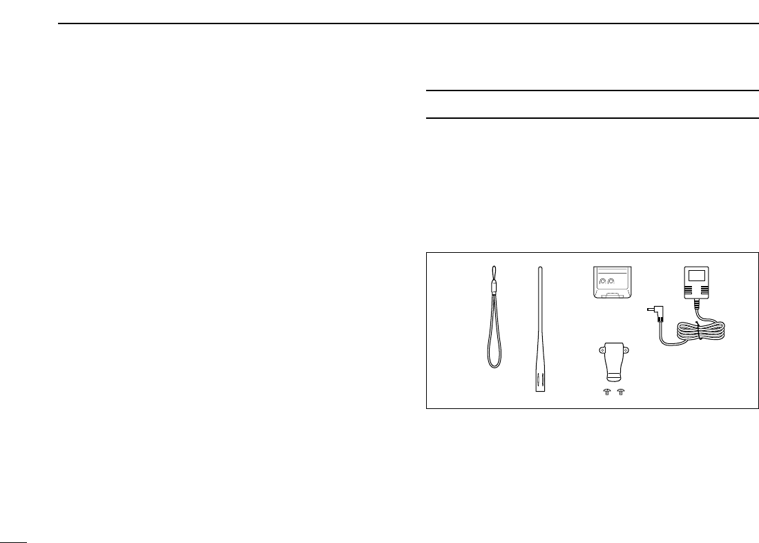
SUPPLIED ACCESSORIES
The following accessories are supplied with the transceiver.
qHand strap ………………………………………………… 1
wAntenna …………………………………………………… 1
eBattery pack* ……………………………………………… 1
rBattery charger* …………………………………………… 1
tBelt clip (with screws) ………………………………… 1 set
*Not supplied with some versions.
re
q
t
w
v
1
1
ACCESSORY ATTACHMENT
1
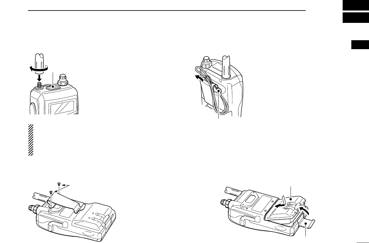
■Antenna
Insert the supplied antenna into the
antenna connector and screw down
the antenna as shown at left.
NEVER hold the antenna when carry-
ing the transceiver.
KEEP the jack cover attached when
jack is not in use to protect the con-
nector from dust and moisture.
✔
For your information
Third-party antennas may increase transceiver perfor-
mance. An optional AD-92SMA
ANTENNA CONNECTOR
ADAPTER
is available to connect an antenna with a BNC
connector.
■Belt clip
■Handstrap
Slide the handstrap through the loop
on the top of the belt clip as illustrated
at left. Facilities carrying.
■Battery pack
Attach the Li-Ion battery pack (BP-217) or battery case (BP-
216) as illustrated below.
• Charge the Li-Ion battery pack before use. (pgs. 10, 11)
Battery pack/
Battery case
Latch
q
w
Handstrap
Supplied screws* *USE the supplied screws
only.
If the screws that longer
than the supplied are
used, the belt clip cannot
be attached properly,
and also may damage
the transceiver.
Jack cover
2
PANEL DESCRIPTION
2
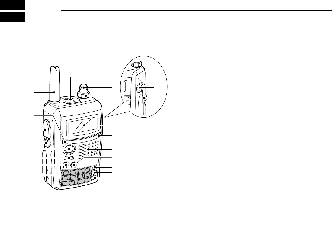
■Front, top and side panels
qANTENNA CONNECTOR (p. 1)
Connects the supplied antenna.
• An optional AD-92SMA adapter (p. 00) is available for connect-
ing an antenna with a BNC connector.
wTX/RX INDICATOR [TX/RX] (p. 24)
Lights green while receiving a signal or when the squelch
is open; lights red while transmitting.
ePTT SWITCH [PTT] (p. 24)
Push and hold to transmit, release to receive.
rSQUELCH KEY [SQL]
➥Push and hold to open the squelch temporarily and
monitor the operating frequency. (p. 22)
➥While pushing and holding this key, rotate [DIAL] to ad-
just the squelch level. (p. 21)
tMENU/LOCK KEY [MENU/LOCK]
➥Push to toggle menu screen indication ON and OFF.
(p. 85)
➥Push and hold for 1 sec. to toggle the lock function ON
and OFF. (p. 25)
yPOWER KEY [PWR]
Push and hold for 1 sec. to turn the transceiver power ON
and OFF.
uMAIN/DUAL KEY [MAIN/DUAL]
➥Push to select the main band between A and B bands.
(p. 26)
➥Push and hold for 1 sec. to toggle the dualwatch func-
tion ON and OFF. (p. 25)
iKEYPAD (pgs. 4, 5)
q
w
!5
Function display
Internal microphone
Speaker
!2
!6
e
r
t
y
u
i
!4
!3
o
!0
!1
!7

3
2
PANEL DESCRIPTION
2
oCALL/RX➝CS KEY [CALL/RX➝CS]
➥Push to select the call channel/TV channel/weather
channel. (p. 16)
➥During DV mode operation, push and hold for 1 sec. to
set the received call signs (station and repeaters) for op-
eration. (p. 47)
➥Enters or sends the DTMF code “C.” (p. 105)
!0MEMORY/SELECT MEMORY WRITE KEY [MR/S.MW]
➥Push to select memory mode. (p. 15)
➥During memory mode operation, push to toggle be-
tween memory and memory bank mode. (p. 68)
➥Push and hold for 1 sec. to enter select memory write
mode. (p. 64)
➥Enters or sends the DTMF code “B.” (p. 105)
!1VFO/MHz KEY [VFO/MHz]
➥Push to toggle select VFO mode. (p. 15)
➥During VFO mode operation, push and hold for 1 sec. to
select and toggle 1 MHz and 10 MHz tuning steps
(p. 18)
!2BAND KEY [BAND]
➥During VFO mode operation, push to select an operat-
ing frequency band. (pgs. 16, 17)
➥During memory mode, push to select a memory bank.
(p. 68)
➥Enters or sends the DTMF code “D.” (p. 105)
!3EXTERNAL DC IN JACK [DC IN]
➥Connects the supplied wall charger, BC-167, to charge
the attached battery pack. (p. 10)
➥Connect an external DC power supply through the op-
tional CP-12L or CP-19R for external DC operation.
(p. 13)
!4DATA JACK [DATA]
Connects a PC through the optional data communication
cable, OPC-1529, for slow-speed data communication or
control the transceiver remotely using with the operational
RS-91 (OPC-1529 is supplied). (p. 56)
!5VOLUME CONTROL [VOL]
Rotate to adjust the audio output level. (p. 20)
!6CONTROL DIAL [DIAL]
➥Rotate to tune the operating frequency. (p. 18)
➥While pushing and holding [BAND], selects the operat-
ing band in VFO mode. (p. 18)
➥While scanning, changes the scanning direction. (p. 75)
➥While pushing and holding [SQL], sets the squelch
level. (p. 21)
➥While pushing and holding [BAND], selects the pro-
grammed bank in memory mode. (p. 68)
!7EXTERNAL SPEAKER/MICROPHONE JACK [MIC/SP]
Connect an optional speaker-microphone or headset, if de-
sired.
See pgs. 125 and 126 for a list of available options.

4
2PANEL DESCRIPTION
DDKEYPAD
KEY Pushed momentarily Pushed and held for 1 sec.
• Inputs digit ‘1’ for frequency input, memory channel selection,
etc.
• While pushing [PTT], this key sends the DTMF code “1.”
• Inputs digit ‘2’ for frequency input, memory channel selection,
etc.
• While pushing [PTT], this key sends the DTMF code “2.”
• Inputs digit ‘3’ for frequency input, memory channel selection,
etc.
• While pushing [PTT], this key sends the DTMF code “3.”
• Inputs digit ‘4’ for frequency input, memory channel selection,
etc.
• While pushing [PTT], this key sends the DTMF code “4.”
• Inputs digit ‘5’ for frequency input, memory channel selection,
etc.
• While pushing [PTT], this key sends the DTMF code “5.”
• Inputs digit ‘6’ for frequency input, memory channel selection,
etc.
• While pushing [PTT], this key sends the DTMF code “6.”
• Displays the simple band scope and sweeps once. (p. 23)
• Starts a scan. (p. 75)
• Toggles the transmit output power between high and low. (p. 24)
- “LOW” appears when low power is selected.
- While pushing and holding this key, with [DIAL] operation also
selects the output power.
• Activates the following duplex functions in order.
- Minus duplex operation— “–DUP” appears.
- Plus duplex operation— “+DUP” appears.
- Simplex operation— no duplex indicator appears.
- While pushing and holding this key, with [DIAL] operation also
selects the duplex function.
• Turn the frequency skip function ON and OFF in VFO mode
(p. 28), or set the memory channel as the following skip chan-
nel in memory mode in order. (p. 28)
- Skip channel— “SKIP” appears.
- Frequency skip channel— “PSKIP” appears.
- Non-skip channel— no skip indicator appears.
• Turn the memory name, bank name indication ON and OFF.
(p. 70)
5
2
PANEL DESCRIPTION
2
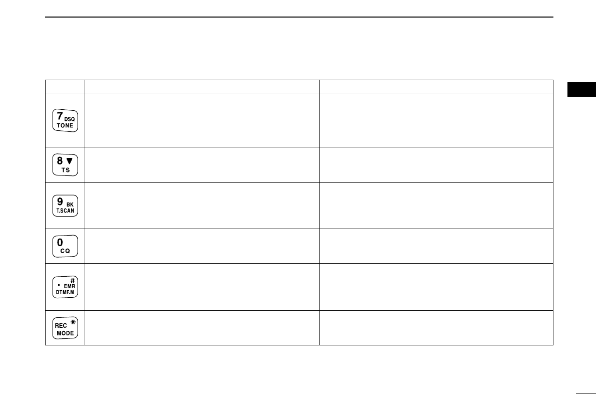
KEY Pushed momentarily Pushed and held for 1 sec.
• Inputs digit ‘7’ for frequency input, memory channel selection,
etc.
• While pushing [PTT], this key sends the DTMF code “7.”
• Inputs digit ‘8’ for frequency input, memory channel selection,
etc.
• While pushing [PTT], this key sends the DTMF code “8.”
• Inputs digit ‘9’ for frequency input, memory channel selection,
etc.
• While pushing [PTT], this key sends the DTMF code “9.”
• Inputs digit ‘0’ for frequency input, memory channel selection,
etc.
• While pushing [PTT], this key sends the DTMF code “0.”
• Inputs MHz digit for frequency input.
• While pushing [PTT], this key sends the DTMF code “F (#).”
• During DV mode operation, selects the record track for voice
memory. (p. 62)
• While pushing [PTT], this key sends the DTMF code “E (✱).”
• During FM/FM-N mode operation, selects repeater tone, tone
squelch, DTCS squelch and no tone operation in sequence.
(p. 111)
• During DV mode operation, selects digital call sign, digital code
and no tone operation in sequence. (p. 111)
• Selects tuning step selection. (p. 18)
• During FM/FM-N mode operation, starts tone scan function.
(p. 114)
• During DV mode operation, selects break-in operation mode.
(p. 51)
• During DV mode operation, set “CQCQCQ” for station’s call sign
for operation.
• Select DTMF memory mode. (p. 106)
• During DV mode operation, keep pushing and holding until 3
short and 1 long beeps are emitted to turn the EMR mode oper-
ation ON. (p. 56)
• Selects the operating mode.
6
2PANEL DESCRIPTION
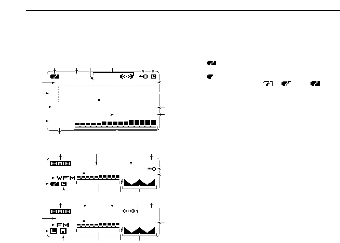
■Function display
qBATTERY INDICATOR (pgs. 10, 12)
➥“ ” (battery indicators) appear when the Li-Ion bat-
tery pack has attached.
➥“ ” appears when the battery pack must be charged.
➥The indicators show “ ,” “ ” and “ ” in se-
quence while charging the attached battery pack.
wDUPLEX INDICATORS (p. 29)
“+DUP” appears when plus duplex, “–DUP” appears when
minus duplex (repeater operation) is selected.
ePRIORITY WATCH INDICATOR (p. 83)
Appears when priority watch is in use.
rTONE INDICATORS
• While operating in FM mode;
➥“TONE” appears while the subaudible tone encoder is
in use. (p. 111)
➥“TSQL” appears while the tone squelch function is in
use. (p. 111)
➥“DTCS” appears while the DTCS squelch function is in
use. (p. 111)
➥“S” appears with the “TSQL” or “DTCS” indicator
while the pocket beep function (with CTCSS or DTCS) is
in use. (p. 111)
• While operating in DV mode;
➥“DSQL” appears while the call sign squelch function is
in use. (p. 111)
➥“CSQL” appears while the digital code squelch function
is in use. (p. 111)
MemoName
µ
PRIO EMR
DSQL
DV
B
LOW
ATT
439706
PSKIP
-DUP
25
000
PS
PRIOPRIO
25
µ
000000
88 100
DTCS
PS
PRIOPRIO
-DUP
75
µ
000000
439706
q
!6 i e o
we r ty
!1
!8!1y !4
!2
!3
!7
q
!4
!5
!6
!7 u
t
!0
!6 w r e o
!8!1!2 !4
!7
i
!3
!0
i
o
!0
• Dualwatch indication
• Single band indication

7
2
PANEL DESCRIPTION
2
➥“S” appears with the “DSQL” or “CSQL” indicator
while the pocket beep function (with sigita call sign or dig-
ital code squelch) is in use. (p. 111)
tKEY LOCK INDICATOR (pgs. 25, 115)
Appears when the key lock function is activated.
yAUTO POWER OFF INDICATOR (p. 88)
Appears when the auto power OFF function is in use.
uEMR MODE INDICATOR (p. 56)
Appears when the EMR mode operation is selected.
iFREQUENCY READOUT
Displays a variety of information, such as an operating fre-
quency, set mode contents, memory names.
• The decimal point blinks during scan.
oSKIP INDICATORS (pgs. 79, 80)
➥“SKIP” appears when the selected memory channel is
set as a skip channel.
➥“P SKIP” appears when the displayed frequency is set
as a skip frequency.
!0MEMORY CHANNEL NUMBER INDICATOR
➥Shows the selected memory channel number. (pgs. 64,
65)
➥“C” appears when the call channel is selected. (pgs. 16,
65)
➥“WX” appears when the weather channel is selected.
(pgs. 16, 116)
➥“TV” appears when the TV channel is selected.
(pgs. 16, 28)
!1S/RF METER
➥Shows the relative signal strength while receiving sig-
nals.
➥Shows the output power level while transmitting. (p. 24)
!2ATTENUATOR INDICATOR (p. 22)
Appears when the RF attenuator is in use.
!3LOW POWER INDICATOR (p. 24)
➥“LOW” appears when the low power is selected.
➥No indicator appears when the high power is selected.
!4MEMORY INDICATOR (p. 64)
Appears when memory mode is selected.
!5NAME INDICATOR (p. 70)
During memory mode operation, the programmed memory
or memory bank name is displayed.
!6MAIN BAND INDICATOR (p. 14)
Shows which operating band, “A” or “B,” is selected for the
main band.
!7OPERATING MODE INDICATOR (p. 21)
Shows the selected operating mode.
• DV, FM, FM-N, WFM and AM are available, depending on oper-
ating band.
!8SIMPLE BAND SCOPE INDICATOR (p. 23)
When the simple band scope function is in used, shows
the band conditions.

8
BATTERY CHARGING
3
■Caution
•RDANGER! Use and charge only specified Icom battery
packs with Icom radios. Only Icom battery packs are tested
and approved for use with Icom radios. Using third-party or
counterfeit battery packs may cause smoke, fire, or cause
the battery to burst.
DDBattery caution
•RDANGER! DO NOT hammer or otherwise impact the bat-
tery. Do not use the battery if it has been severely impacted
or dropped, or if the battery has been subjected to heavy
pressure. Battery damage may not be visible on the outside
of the case. Even if the surface of the battery does not show
cracks or any other damage, the cells inside the battery may
rupture or catch fire.
•RDANGER! NEVER use or leave battery pack in areas
with temperatures above +60˚C (+140˚F). High temperature
buildup in the battery, such as could occur near fires or
stoves, inside a sun heated car, or in direct sunlight may
cause the battery to rupture or catch fire. Excessive temper-
atures may also degrade battery performance or shorten
battery life.
•RDANGER! DO NOT expose the battery to rain, snow,
seawater, or any other liquids. Do not charge or use a wet
battery. If the battery gets wet, be sure to wipe it dry before
using. The battery is not waterproof.
•RDANGER! NEVER incinerate used battery pack since in-
ternal battery gas may cause it to rupture, or may cause an
explosion.
•RDANGER! NEVER solder the battery terminals, or
NEVER modify the battery pack. This may cause heat gen-
eration, and the battery may burst, emit smoke or catch fire.
•RDANGER! Use the battery only with the transceiver for
which it is specified. Never use a battery with any other
equipment, or for any purpose that is not specified in this in-
struction manual.
•RDANGER! If fluid from inside the battery gets in your
eyes, blindness can result. Rinse your eyes with clean
water, without rubbing them, and see a doctor immediately.
•WARNING! Immediately stop using the battery if it emits an
abnormal odor, heats up, or is discolored or deformed. If any
of these conditions occur, contact your Icom dealer or dis-
tributor.
•WARNING! Immediately wash, using clean water, any part
of the body that comes into contact with fluid from inside the
battery.
Misuse of Lithium-Ion batteries may result in the follow-
ing hazards: smoke, fire, or the battery may rupture.
Misuse can also cause damage to the battery or degra-
dation of battery performance.

9
3
BATTERY CHARGING
3
•WARNING! NEVER put the battery in a microwave oven,
high-pressure container, or in an induction heating cooker.
This could cause a fire, overheating, or cause the battery to
rupture.
•CAUTION! Always use the battery within the specified tem-
perature range, –20˚C to +60˚C (–4˚F to +140˚F). Using the
battery out of its specified temperature range will reduce the
battery’s performance and battery life.
•CAUTION! Shorter battery life could occur if the battery is
left fully charged, completely discharged, or in an excessive
temperature environment (above +50˚C; +122˚F) for an ex-
tended period of time. If the battery must be left unused for a
long time, it must be detached from the radio after discharg-
ing. You may use the battery until the battery indicator
shows half-capacity, then keep it safely in a cool dry place
with the temperature between –20˚C to +20˚C (–4˚F to
+68˚F).
DDCharging caution
•RDANGER! NEVER charge the battery pack in areas with
extremely high temperatures, such as near fires or stoves,
inside a sun heated car, or in direct sunlight. In such envi-
ronments, the safety/protection circuit in the battery will acti-
vate, causing the battery to stop charging.
•WARNING! DO NOT charge or leave the battery in the bat-
tery charger beyond the specified time for charging. If the
battery is not completely charged by the specified time, stop
charging and remove the battery from the battery charger.
Continuing to charge the battery beyond the specified time
limit may cause a fire, overheating, or the battery may rup-
ture.
•WARNING! NEVER insert the transceiver (battery attached
to the transceiver) into the charger if it is wet or soiled. This
could corrode the battery charger terminals or damage the
charger. The charger is not waterproof.
•CAUTION! DO NOT charge the battery outside of the spec-
ified temperature range: 0˚C to +35˚C (+32˚F to +95˚F).
Icom recommends charging the battery at +20˚C (+68˚F).
The battery may heat up or rupture if charged out of the
specified temperature range. Additionally, battery perfor-
mance or battery life may be reduced.
10
3BATTERY CHARGING
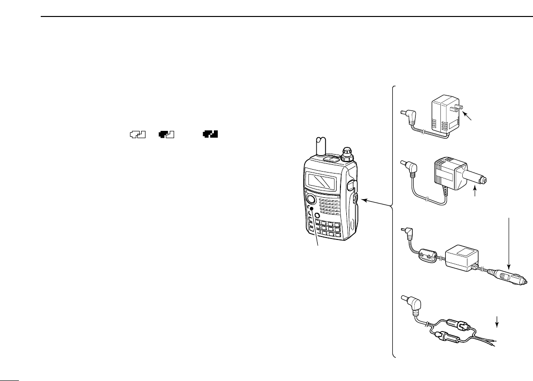
■Regular charging
Prior to using the transceiver for the first time, the battery
pack must be fully charged for optimum life and operation.
DDBattery indicators
The indicators show “ ,” “ ” and “ ” in sequence
while charging, and both indicators disappear when com-
pletely charged.
DDCharging note
• Be sure to turn the transceiver power OFF.
Otherwise the battery pack will not be charged completely or takes
longer charging time periods.
• External DC power operation becomes possible when using
an optional CP-12L, CP-19R or OPC-254L. The attached
battery pack is also charged, except during transmit, simul-
taneously. (see p. 11 for more details)
• The external DC power supply voltage must within 10–16 V
to charge the battery pack and operation when using an op-
tional OPC-254L.
• BC-167A/D
• CP-12L (Optional)
• CP-19R (Optional)
• OPC-254L (Optional)
to AC outlet
to cigarette lighter
socket (12 V DC)
to 12 V DC
(power supply)
White: +
Black: _
Transceiver
to
[DC IN]
Turn power OFF while
charging the battery
pack.
• Charging time period:
Approx. 5 hours
11
3
BATTERY CHARGING
3
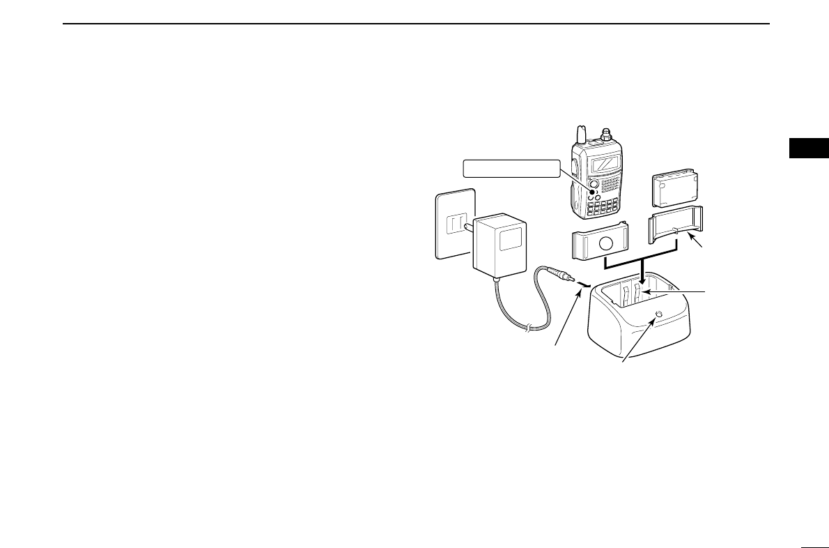
■Rapid charging
The optional BC-139 provides rapid charging of the battery
pack.
• Charging period: 2.5 hours (with BP-217)
DDCharging note
• Be sure to turn the transceiver power OFF.
Detach the battery pack from the transceiver then charge
the battery pack itself, or charge the battery with regular
charging when the transceiver power cannot be turned OFF.
Otherwise the battery pack will not be charged (charging indi-
cator on the BC-139 blinks orange).
• The desktop charger, BC-139, can only be charged BP-217,
other types of rechargeable battery, Ni-Cd or Ni-MH, cannot
be charged.
• If the charging indicator blinks orange, there may be a prob-
lem with the battery pack (or charger). Reinsert the battery
pack or contact your dealer.
A
Transceiver
(with battery pack)
Turn power OFF.
Check the
orientation.
Battery pack
to AC outlet
BC-139 (optional)
Desktop charger
to [AC ADAPTER]
Adapter (supplied
with BC-139)
Charging indicator
Charging : Orange
Finished : Green
Charging
terminal
BC-123
(supplied
with BC-139)
12
3BATTERY CHARGING
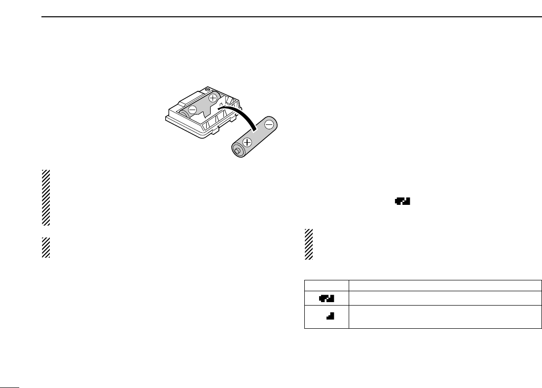
■Optional battery case
➥Install 2 R6 (AA) size alka-
line batteries into the op-
tional BP-216
BATTERY
CASE
.
• Be sure to observe the cor-
rect polarity.
A built-in step-up convertor in the BP-216 increases the
voltage up to 5 V DC.
Approx. 100 mW of output power transmission is possible
with the BP-216 operation. Also, no transmit output power
selection is available.
Keep battery contacts clean. It’s a good idea to clean bat-
tery terminals once a week.
DBattery information
The batteries may seem to have low capacity when used in
low temperatures such as –10°C (+14°F) or below. Keep the
battery case or pack warm in this case.
DBattery replacement
When the batteries become exhausted, the function display
may blink or have a lower contrast. In these cases, replace
all batteries with new, same brand, alkaline batteries.
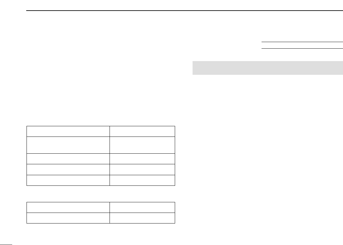
■Battery information
DDBattery life
The transceiver is operatable with the BP-217 as follows.
However, half a hour becomes shorter when DV mode is op-
erated.
•VHF band : Approx. 5 hours
•UHF band : Approx. 4.5 hours
(Tx: Rx: Stand-by=1: 1: 8)
DDBattery indicator
The battery indicator, “ ,” appears only when the BP-217
is attached to the transceiver.
The battery indicator does not appear when turning power
ON after the charging is completed without disconnecting
the battery charger or external DC power.
Indication Battery condition
The battery has ample capacity.
The battery is nearing exhaustion. Charging is neces-
sary.
13
3
BATTERY CHARGING
3
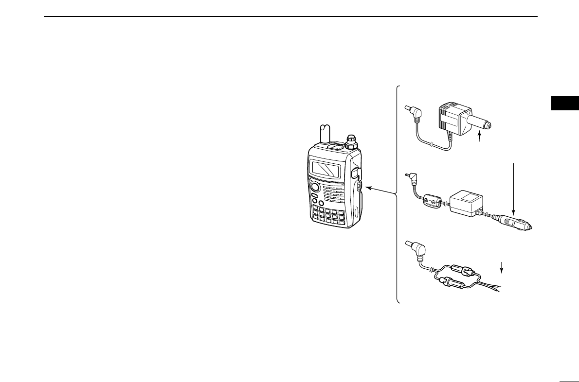
■External DC power operation
An optional cigarette lighter cable (CP-12L or CP-19R; for 12 V
cigarette lighter socket) or external DC power cable (OPC-254L)
can be used for external power operation.
DDOperating note
• Power supply range is between 10.0–16.0 V DC.
NEVER CONNECT OVER 16 V DC directly into [DC IN]
jack of the transceiver.
•BE SURE to use CP-12L,CP-19R or OPC-254L when con-
necting regulated 12 V DC power supply.
Purchase extra DC-DC converter if connecting the trans-
ceiver through optional CP-12L, CP-19R or OPC-254L to a
24 V DC power source.
• The voltage of the external power supply must be within
10–16 V DC when using either CP-12L, CP-19R or OPC-
254L, otherwise, the attached battery pack’s power may be
used for operation.
• Up to 5 W (approx.) of maximum output power is provided
with the external DC power operation, however, when the
supplied voltage exceeds 14 V, the built-in protection circuit
activates to reduce the transmit output power to 0.5 W (ap-
prox.).
• Disconnect the cables from the transceiver when not using
it. Otherwise, the vehicle battery will become exhausted.
• The power save function is deactivated automatically during
external DC power operation (more than 10 V DC).
• CP-12L (Optional)
• CP-19R (Optional)
• OPC-254L (Optional)
to cigarette lighter
socket (12 V DC)
to 12 V DC
(power supply)
White: +
Black: _
Transceiver
to
[DC IN]
14
FREQUENCY AND CHANNEL SETTING
4
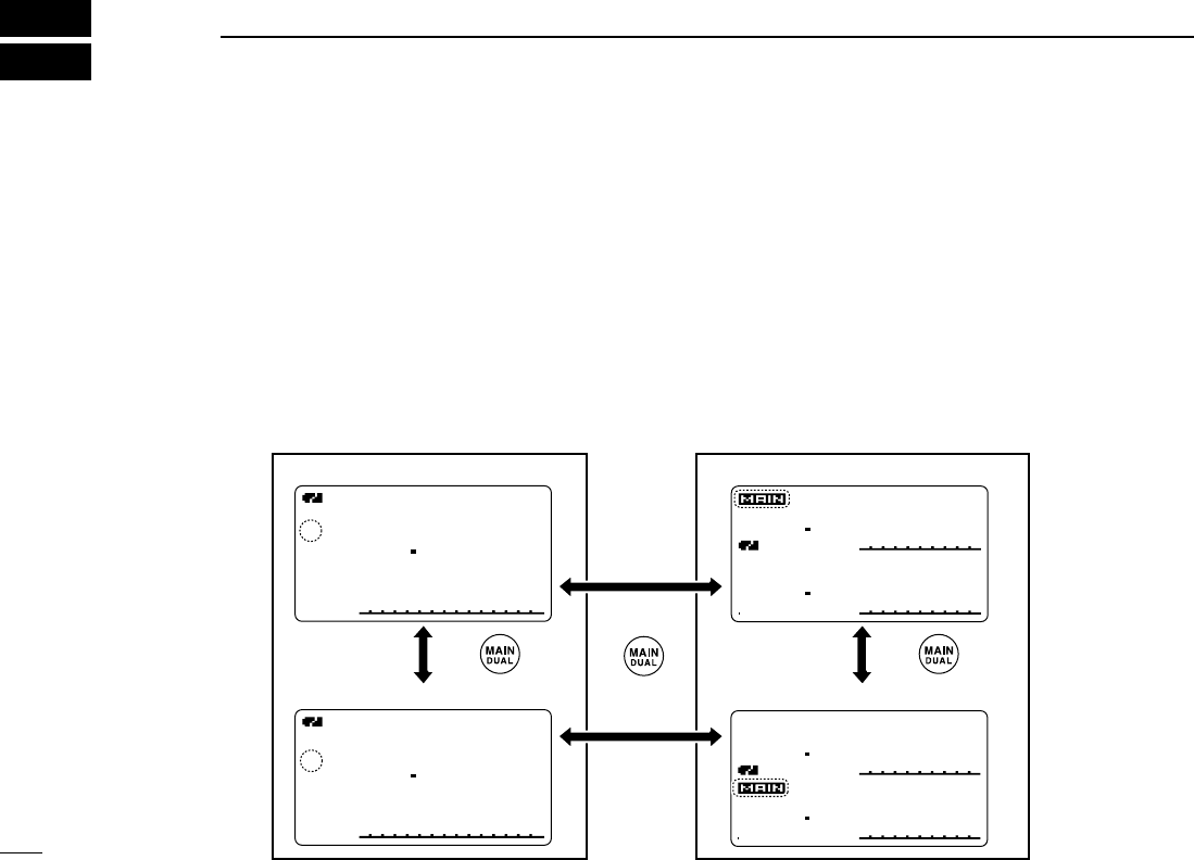
■Main band selection
The IC-91A/91AD has two independent operating band as A
band (VFO A) and B band (VFO B). A band (VFO A) can operate
0.495 MHz to 999.990 MHz*, and B band (VFO B) can operate
118 MHz to 174 MHz and 350 MHz to 470 MHz.
*Some frequency ranges are prohibited for the USA version due to
local regulation.
DDHow to change the main band
➥Push [MAIN/DUAL] to toggle between A and B band.
➥Push and hold [MAIN/DUAL] for 1 sec. to turn the dual-
watch operation ON and OFF.
• While dualwatch operation, the display indicates the upper side
as A band and lower side as B band.
➥During dualwatch operation, push [MAIN/DUAL] to select
upper side (A band) or lower side (B band) as main band (op-
erating band) alternately.
DTCS
DTCS
W
PS
EM
W
PS
FMFM
PRIO
PRIO
+DUP+DUP
+DUP+DUP
FM
146010
440000
25
50
µ
000000
µ
000000
DTCS
DTCS
W
PS
EMEM
W
PS
FMFM
PRIO
PRIO
+DUP+DUP
+DUP+DUP
FM
146010
440000
25
50
µ
000000
µ
000000
A
MemoName
µ
PRIOPRIO WXWX EMREMR
DTCSDTCS
FMFM
LOWLOW
ATTATT
146010
PSKIPSKIP
+DUP+DUP
2525
000
MemoName
µ
PRIOPRIO WXWX EMREMR
DTCSDTCS
FMFM
B
LOWLOW
ATTATT
440000
PSKIPSKIP
+DUP+DUP
2525
000
Push Push
• Selecting A band • Selecting upper side as main band
• Selecting lower side as main band
• Selecting B band
Push
DTCS
DTCS
W
PS
EM
W
PS
FM
PRIO
PRIO
+DUP
+DUP
FM
146 010
440 000
25
50
µ
000
µ
000
DTCS
DTCS
W
PS
EM
W
PS
FM
PRIO
PRIO
+DUP
+DUP
FM
146 010
440 000
25
50
µ
000
µ
000
A
MemoName
µ
PRIO WX EMR
DTCS
FM
LOW
ATT
146010
P SKIP
+DUP
25
000
MemoName
µ
PRIO WX EMR
DTCS
FM
B
LOW
ATT
440000
P SKIP
+DUP
25
000
Single band operation Dualwatch operation
for 1 sec.
15
4
FREQUENCY AND CHANNEL SETTING
4
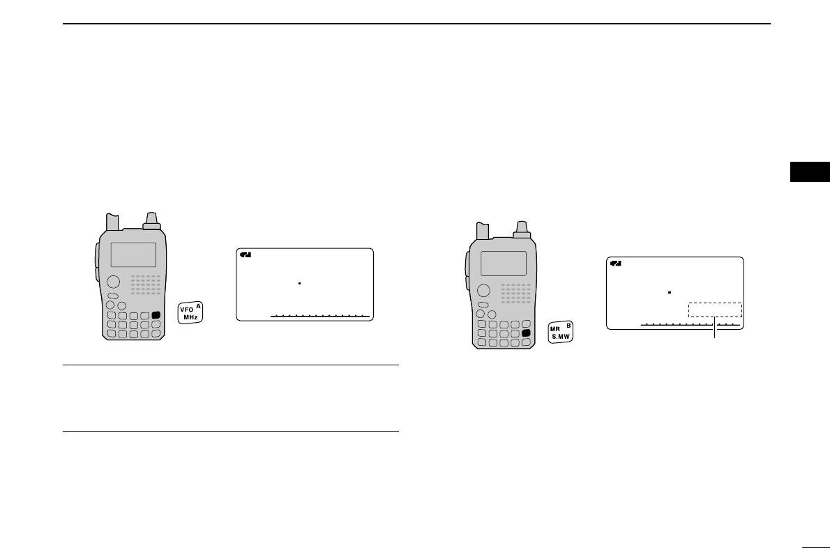
■Mode selection
DDVFO mode
VFO mode is used for the desired frequency setting within the
frequency coverage.
➥Push [VFO/MHz] to select VFO mode.
What is VFO?
VFO is an abbreviation of Variable Frequency Oscillator. Fre-
quencies for both transmitting and receiving are generated
and controlled by the VFO.
DDMemory mode
Memory mode is used for operation of memory channels
which have programmed frequencies.
qPush [MR/S.MW] to select memory mode.
•“
µµ” appears when memory mode is selected.
wRotate [DIAL] to select the desired memory channel.
• Only programmed memory channels can be selected.
• Direct memory channel entering selects the desired memory
channel. (p. 64)
• See p. 66 for memory programming details.
A
MemoName
µ
PRIOPRIO WXWX EMREMR
DTCSDTCS
FMFM
LOWLOW
ATTATT
146010
PSKIP
+DUP+DUP
25
000000
• Memory mode indication
Appear
A
MemoNameMemoName
µ
PRIOPRIO WXWX EMREMR
DTCSDTCS
FMFM
LOWLOW
ATTATT
146010
PSKIP
+DUP+DUP
25
000000
• VFO mode indication
16
4FREQUENCY AND CHANNEL SETTING
DDCall/TV*/Weather†channels
Call channels are used for most-often used frequencies for
quick recall.
*Appears only when TV channels are programmed via the
optional RS-91. Also available for A band operation only.
†Available for the USA version only.
qPush [CALL/RX➝CS] several times to select call chan-
nels/TV channels (A band only)/Weather channels.
•Call/TV/Weather channels can be selected in sequence.
wRotate [DIAL] to select the desired channel.
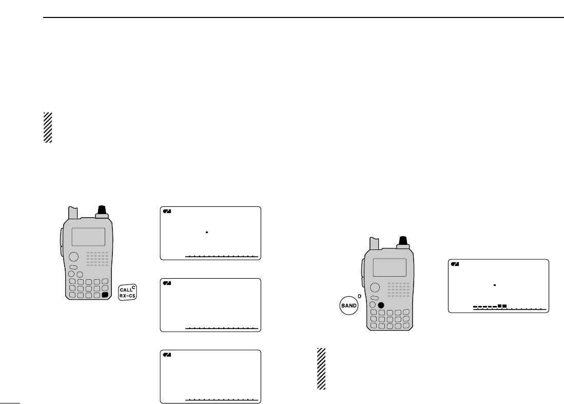
■Operating band selection
The transceiver can receive the AM broadcast, HF bands,
50 MHz, FM broadcast, VHF air, 144 MHz, 300 MHz,
400 MHz or 800 MHz* bands. (Some bands are not selectable
for B band operation. See next page for details.)
➥In VFO mode, push [BAND] several times to select the de-
sired frequency band.
•If the other than VFO mode is selected, such as a memory chan-
nel/call channel/TV channel/Weather channel, push [VFO/MHz]
to select VFO mode first, then push [BAND] to select the desired
band.
➥While pushing and holding [BAND], rotating [DIAL] also
selects frequency band.
Available frequency bands are different depending on ver-
sion. See the specification for details. (pgs. 123, 124)
*Some frequency ranges are prohibited for the USA ver-
sion due to local regulation.
A
MemoName
µ
PRIOPRIO WXWX EMREMR
DTCSDTCS
FMFM
LOWLOW
ATTATT
146010
PSKIP
+DUP+DUP
25
000000
[DIAL]
[DIAL]
A
MemoNameMemoName
µ
PRIOPRIO WXWX EMREMR
DTCSDTCS
FMFM
LOWLOW
ATTATT
146010
PSKIP
+DUP+DUP
25
C0C0
TVTV
A
MemoNameMemoName
µ
PRIOPRIO WXWX EMREMR
DTCSDTCS
WFMWFM
LOWLOW
ATTATT
10 ch
PSKIP
+DUP+DUP
25
WXWX
A
MemoNameMemoName
µ
PRIOPRIO WXWX EMREMR
DTCSDTCS
WFMWFM
LOWLOW
ATTATT
1
PSKIP
+DUP+DUP
25
• Call channel indication
• TV channel indication
• Weather channel indication
17
4
FREQUENCY AND CHANNEL SETTING
1
2
3
4
5
6
7
8
9
10
11
12
13
14
15
16
17
18
19
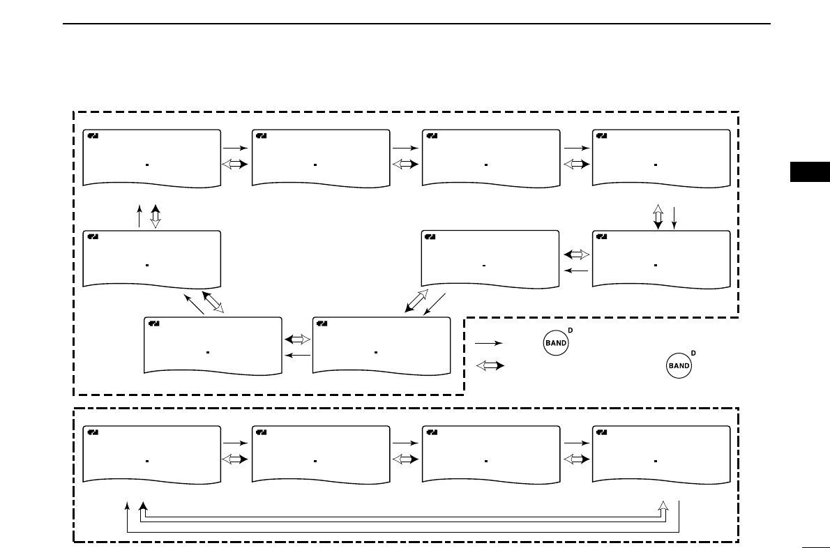
• Available frequency bands
A
MemoName
PRIOPRIO WXWX EMREMR
DTCSDTCS
AMAM
118000
PSKIP
+DUP+DUP
25
A
MemoNameMemoName
PRIOPRIO WXWX EMREMR
DTCSDTCS
AMAM
B
118000
PSKIP
+DUP+DUP
25
A
MemoName
PRIOPRIO WXWX EMREMR
DTCSDTCS
FMFM
B
146010
PSKIP
+DUP+DUP
25
A
MemoNameMemoName
PRIOPRIO WXWX EMREMR
DTCSDTCS
FMFM
B
370000
PSKIP
+DUP+DUP
25
A
MemoName
PRIOPRIO WXWX EMREMR
DTCSDTCS
FMFM
B
440000
PSKIP
+DUP+DUP
25
A
MemoNameMemoName
PRIOPRIO WXWX EMREMR
DTCSDTCS
FMFM
850000
PSKIP
+DUP+DUP
25
A
MemoNameMemoName
PRIOPRIO WXWX EMREMR
DTCSDTCS
FMFM
440000
PSKIP
+DUP+DUP
25
A
MemoNameMemoName
PRIOPRIO WXWX EMREMR
DTCSDTCS
AMAM
370000
PSKIP
+DUP+DUP
25
A
MemoNameMemoName
PRIOPRIO WXWX EMREMR
DTCSDTCS
FMFM
146010
PSKIP
+DUP+DUP
25
A
MemoNameMemoName
PRIOPRIO WXWX EMREMR
DTCSDTCS
AMAM
001620
PSKIP
+DUP+DUP
25
A
MemoName
PRIOPRIO WXWX EMREMR
DTCSDTCS
AMAM
005000
PSKIP
+DUP+DUP
25
A
MemoNameMemoName
PRIOPRIO WXWX EMREMR
DTCSDTCS
FMFM
051 000
PSKIP
+DUP+DUP
25
A
MemoName
PRIOPRIO WXWX EMREMR
DTCSDTCS
WFMWFM
076 000
PSKIP
+DUP+DUP
25
AM broadcast band HF band
• A band
• B band
50 MHz band
800 MHz band
400 MHz band
400 MHz band
FM broadcast band
VHF air band
VHF air band
144 MHz band
144 MHz band
300 MHz band
300 MHz band
: Push
: Rotating [DIAL] while pushing
Initial frequencies shown differ according to version.
18
4FREQUENCY AND CHANNEL SETTING
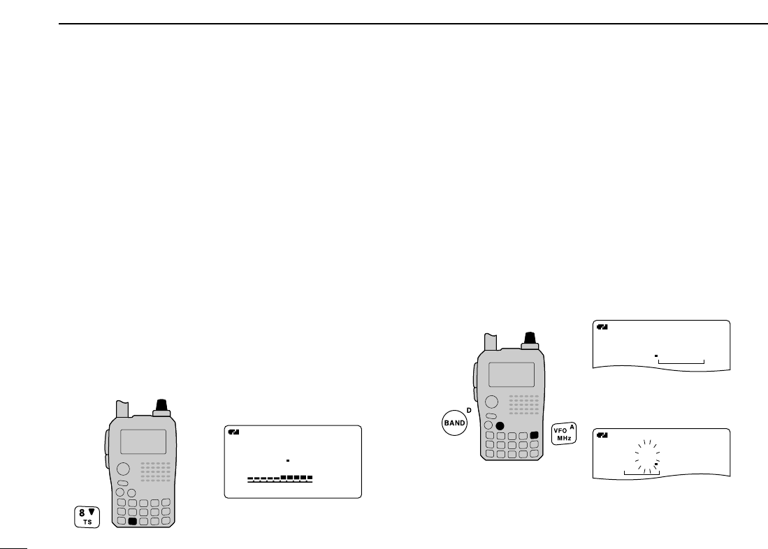
■Setting a tuning step
The tuning step can be selected for each frequency band.
The following tuning steps are available for the IC-91A/91AD.
•5.0 kHz* •6.25 kHz* •8.33 kHz†•9.0 kHz‡•10.0 kHz
•12.5 kHz •15.0 kHz •20.0 kHz •25.0 kHz •30.0 kHz
•50.0 kHz •100.0 kHz • 125.0 kHz • 200.0 kHz
* Appears for below the 600 MHz bands only.
†Appears for the VHF air band only.
‡Appears for the AM broadcast band only.
DDTuning step selection
qPush [VFO/MHz] to select VFO mode, if necessary.
wPush [BAND] to select the desired frequency band.
•Or, while pushing and holding [BAND], rotate [DIAL] to select
the desired frequency band.
ePush and hold [8/TS] for 1 sec. to enter tuning step set mode.
rRotate [DIAL] to select the desired tuning step.
tPush [8/TS] (or [VFO/MHz]) to return to VFO mode.
■Setting a frequency
DDUsing the dial
qPush [VFO/MHz] to select VFO mode, if necessary.
wSelect the desired frequency band with [BAND].
•Or, while pushing and holding [BAND], rotate [DIAL] to select
the desired frequency band.
eRotate [DIAL] to select the desired frequency.
•The frequency changes according to the preset tuning steps.
See the left section for setting the tuning step.
•Push and hold [VFO/MHz] for 1 sec. then rotate [DIAL] to
change the frequency in 1 MHz steps, or push and hold for 1 sec.
again then rotate [DIAL] to change the frequency in 10 MHz
steps. (Each pushing and holding for 1 sec. toggles 1 MHz or
10 MHz tuning steps.)
A
PRIOPRIO WXWX EMREMR
DTCSDTCS
FMFM
146010
+DUP+DUP
25
A
PRIOPRIO WXWX EMREMR
DTCSDTCS
FMFM
146010
+DUP+DUP
25
[DIAL]
[DIAL] changes the fre-
quency according to the se-
lected tuning step.
After pushing and holding
[
VFO/MHz
] for 1 sec., [DIAL]
changes the frequency in 1
MHz/10 MHz steps.
A
PRIOPRIO WXWX EMREMR
DTCSDTCS
FMFM
146010
P
+DUP+DUP
25
SET-TS:5.0kHz
µ
000000
SKIP
[DIAL]
5 kHz tuning step
19
4
FREQUENCY AND CHANNEL SETTING
1
2
3
4
5
6
7
8
9
10
11
12
13
14
15
16
17
18
19
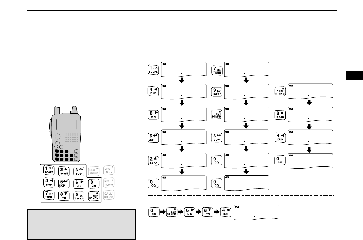
DDUsing the keypad
The frequency can be directly set via numeral
keys.
•When editing a frequency outside of the fre-
quency range, the previously displayed frequency
is automatically recalled after editing last digit.
qPush [VFO/MHz] to select VFO mode, if
necessary.
wEnter the desired frequency via the keypad.
A
PRIO WX
DTCS
FM
730 000
+DUP
2525
A
PRIO WX
DTCS
FM
790000
+DUP
2525
A
PRIO WX
DTCS
FM
079 300
+DUP
2525
A
PRIO WX
DTCS
FM
079300
+DUP
2525
A
PRIO WX
DTCS
FM
079 300
+DUP
2525
A
PRIO WX
DTCS
FM
079 300
+DUP
2525
A
PRIO WX
DTCS
FM
146 520
+DUP
2525
A
PRIO WX
DTCS
FM
146520
+DUP
2525
A
PRIO WX
DTCS
FM
146520
+DUP
2525
A
PRIO WX
DTCS
FM
146 520
+DUP
2525
A
PRIO WX
DTCS
FM
146520
+DUP
2525
A
PRIO WX
DTCS
FM
146520
+DUP
2525
A
PRIO WX
DTCS
FM
146240
+DUP
2525
A
PRIO WX
DTCS
FM
000684
+DUP
2525
A
PRIO WX
DTCS
FM
146240
+DUP
2525
A
PRIO WX
DTCS
FM
146 240
+DUP
2525
A
PRIO WX
DTCS
FM
146240
+DUP
2525
• Editting to 146.520 MHz
• Editting to 79.3 MHz
• Editting to 684 kHz
• Changing 100 kHz
and below.
Editting
146.520 MHz
to 146.240 MHz
Depending on the tuning step setting, 1
kHz digit may not acceptable to input. In
this case, enter “0” as 1 kHz digit, then ro-
tate [DIAL] to set the desired frequency.
20
BASIC OPERATION
5
■Receiving
Make sure charged battery pack (BP-217) or brand new al-
kaline batteries (into BP-216) are installed (pgs. 1, 12).
qPush and hold [PWR] for 1 sec. to turn power ON.
wRotate [VOL] to set the desired audio level.
•The frequency display shows the volume level while setting. See
the section at right for details.
eSet the receiving frequency. (p. 18)
rSet the squelch level. (p. 21)
•While pushing and holding [SQL], rotate [DIAL].
•The first click of [DIAL] indicates the current squelch level.
•“LEVEL 1” is loose squelch (for weak signals) and “LEVEL 9” is
tight squelch (for strong signals).
•“AUTO” indicates automatic level adjustment by a noise pulse
counting system.
•Push and hold [SQL] to open the squelch manually.
tWhen a signal is received:
•Squelch opens and audio is emitted.
•The S/RF-meter shows the relative signal strength level.
■Setting audio volume
➥Rotate [VOL]
to adjust the audio level.
•If squelch is closed, push and hold [SQL] to verify the audio
level.
•The display shows the volume level while setting.
µ
000000
VOLVOL
µ
000000
VOLVOL
µ
000000
VOLVOL
A
MemoName
µ
PRIOPRIO WXWX EMREMR
DTCSDTCS
FMFM
LOWLOW
ATTATT
146010
PSKIP
PSKIP
PSKIP
PSKIP
+DUP+DUP
25
000000
Minimum setting
(no audio)
Volume level indicator
Maximum setting
[VOL]
q [PWR]
e Set frequency
r Set squelch level
w Set audio level
e Select band
r Push for setting
the squelch
(Push to monitor)
21
5
BASIC OPERATION
1
2
3
4
5
6
7
8
9
10
11
12
13
14
15
16
17
18
19
■Setting squelch level
The squelch circuit mutes the received audio signal depend-
ing on the signal strength. The receiver has 9 squelch levels,
a continuously open setting and an automatic squelch setting.
➥While pushing and holding [SQL], rotate [DIAL] to select
the squelch level.
•“LEVEL 1” is loose squelch (for weak signals) and “LEVEL 9” is
tight squelch (for strong signals).
•“AUTO” indicates automatic level adjustment by a noise pulse
counting system.
•“OPEN” indicates continuously open setting.
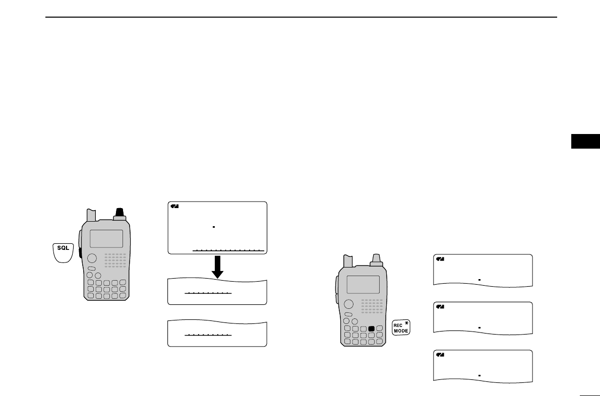
■Operating mode selection
Operating modes are determined by the modulation of the
radio signals. The transceiver has total 5 operating modes (A
band: FM, WFM and AM modes, B band FM, FM-N, AM and
DV modes). The mode selection is stored independently in
each band and memory channels.
Typically, AM mode is used for the AM broadcast stations
(0.495–1.620 MHz) and air band (118–136.995 MHz), and
WFM is used for FM broadcast stations (76–107.9 MHz).
WFM mode cannot be selected above 810 MHz bands for
USA version.
➥Push and hold [REC/MODE] for 1 sec. several times to se-
lect the desired operating mode.
A
FMFM
146010
25
A
WFMWFM
176 000
25
A
AMAM
118000
25
FM mode
WFM mode
AM mode
• Display example
A
MemoNameMemoName
µ
PRIOPRIO WXWX EMREMR
DTCSDTCS
FMFM
LOWLOW
ATTATT
146010
PSKIP
+DUP+DUP
25
000000
SQUELCH:LEVEL9
µ
000000
PSKIP
SQUELCH:AUTO
µ
000000
PSKIP
Automatic squelch
Maximum level
[DIAL]
22
5BASIC OPERATION
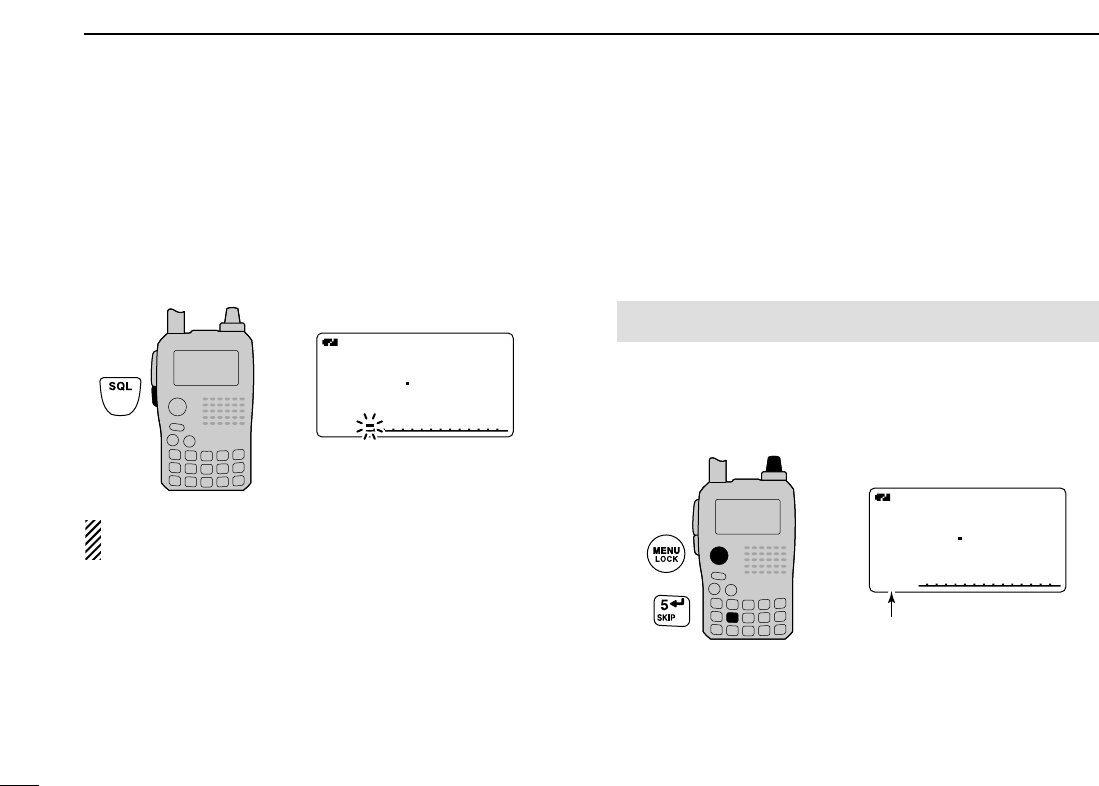
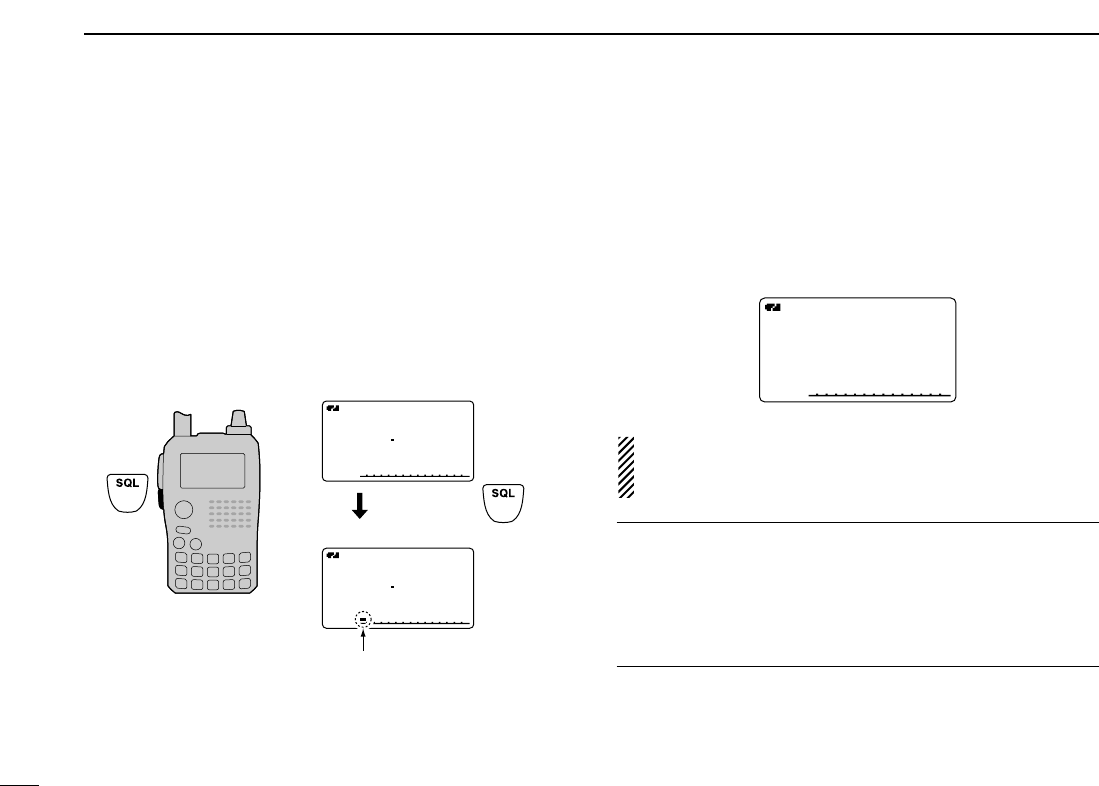
■Monitor function
This function is used to listen to weak signals without disturb-
ing the squelch setting or to open the squelch manually even
when mute functions such as the tone squelch are in use.
➥Push and hold [SQL] to monitor the operating frequency.
•The 1st segment of the S-meter blinks.
The [SQL] key can be set to ‘sticky’operation in set mode.
See page 89 for details.
■Attenuator function
The attenuator prevents a desired signal from distorting when
very strong signals are near the desired frequency or when
very strong electric fields, such as from a broadcasting station,
are near your location. The attenuator gain is about 10 dB.
qEnter “ATTENUATOR” in set mode. (p. ?88
wRotate [DIAL]†to select “ON” or “OFF.”
ePush [5/SKIP](ï)(or [4/DUP](ΩΩ))to return to set mode,
and push [MENU/LOCK] to return to frequency indication.
• “ATT” appears on the function display when “ON” is selected.
†[DIAL] ↔[2/SCAN](∫∫)/[8/TS](√√) [5/SKIP](ï)↔[6/M.N](≈≈)
A
MemoName
µ
PRIOPRIO WXWX EMREMR
DTCSDTCS
FMFM
LOWLOW
ATTATT
146010
PSKIP
+DUP+DUP
25
000000
[DIAL]
Appears.
MENU screen➪SET MODE➪ATTENUATOR
(Push [MENU/LOCK]) (Rotate [DIAL]†, then push [5/SKIP](ï)†.)
A
MemoNameMemoName
µ
PRIOPRIO WXWX EMREMR
DTCSDTCS
FMFM
LOWLOW
ATTATT
146010
PSKIP
+DUP+DUP
25
000000
The 1st segment blinks
23
5
BASIC OPERATION
1
2
3
4
5
6
7
8
9
10
11
12
13
14
15
16
17
18
19
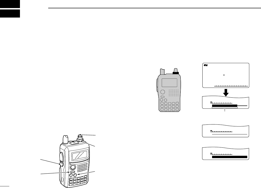
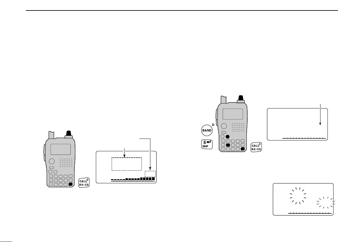
■Band scope
The band scope function allows you to visually check a spec-
ified frequency range around the center frequency.
About the sweeping steps: The specified tuning step in
each frequency band (in VFO mode) is used during
sweep.
DDSingle sweeping
qSet the desired frequency as band scope center frequency.
wPush and hold [1/SCOPE] for 1 sec. to start single sweep-
ing.
•1 short and 1 long beeps sound.
•Signal conditions (strengths) appear starting from the center of
the range.
eRotate [DIAL] to set the highlighted cursor to the desired
waveform and set the frequency of the signal.
rPush [VFO/MHz] to return to normal condition.
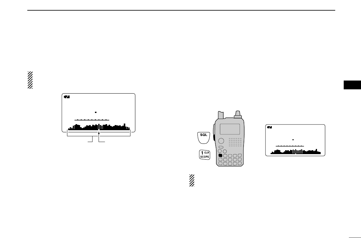
DDContinuous sweeping
qSet the desired frequency as band scope center frequency.
wPush and hold [1/SCOPE] for 3 sec. to start continuous
sweeping.
•2 short beeps sound after 1 short and 1 long beeps.
•Signal conditions (strengths) appear starting from the center of
the range.
ePush and hold [1/SCOPE] for 1 sec. to cancel sweeping.
•Pushing [SQL] also cancels sweeping.
The receive audio during sweeping can be muted in
sounds set mode. See page 102 for details.
PRIOPRIO WXWX EMREMR
DTCSDTCS
FMFM
B
A
145780
P SKIPP SKIP
+DUP+DUP
25
µ
000000
PRIO WX EMR
DTCS
FM
B
A
145780
P SKIPP SKIP
+DUP
2525
µ
000
Sweep markerBand scope indication
24
5BASIC OPERATION
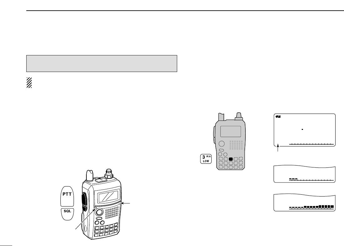
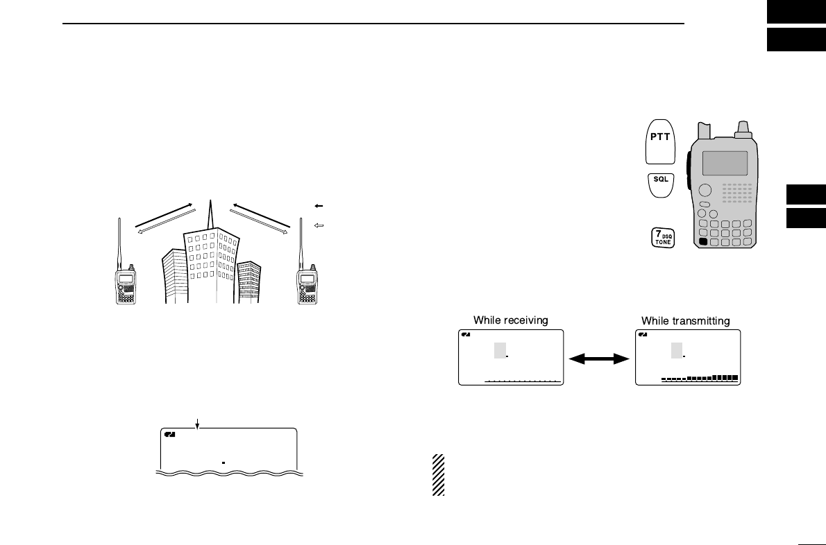
■Transmitting
NOTE: To prevent interference, listen on the channel be-
fore transmitting by pushing and holding [SQL].
qSet the operating frequency. (pgs. 18, 19)
•Transmission is available on the 144 MHz/440 MHz amateur
bands only.
•Select output power if desired. See the section at right for details.
wPush and hold [PTT] to transmit.
•Tx/Rx indicator lights red.
•S/RF meter shows the output power level.
eSpeak into the microphone using your normal voice level.
•DO NOT hold the transceiver too close to your mouth or speak
too loudly. This may distort the signal.
rRelease [PTT] to return to receive.
■Transmit power selection
The transceiver has two output power levels to suit your op-
erating requirements. Low output power during short-range
communications may reduce the possibility of interference to
other stations and will reduce current consumption.
➥
Push and hold [3/LOW] for 1 sec. to toggle the transmit out-
put power between High and Low.
•“LOW” appears when the low power is selected.
A
MemoName
µ
PRIOPRIO WXWX EMREMR
DTCSDTCS
FMFM
LOWLOW
LOWLOW
LOWLOW
ATTATT
146010
PSKIP
+DUP+DUP
25
000000
Appears
Low power transmission
High power transmission
Tx/Rx indicator
Microphone
CAUTION: Transmitting without an antenna will damage
the transceiver.
25
5
BASIC OPERATION
1
2
3
4
5
6
7
8
9
10
11
12
13
14
15
16
17
18
19
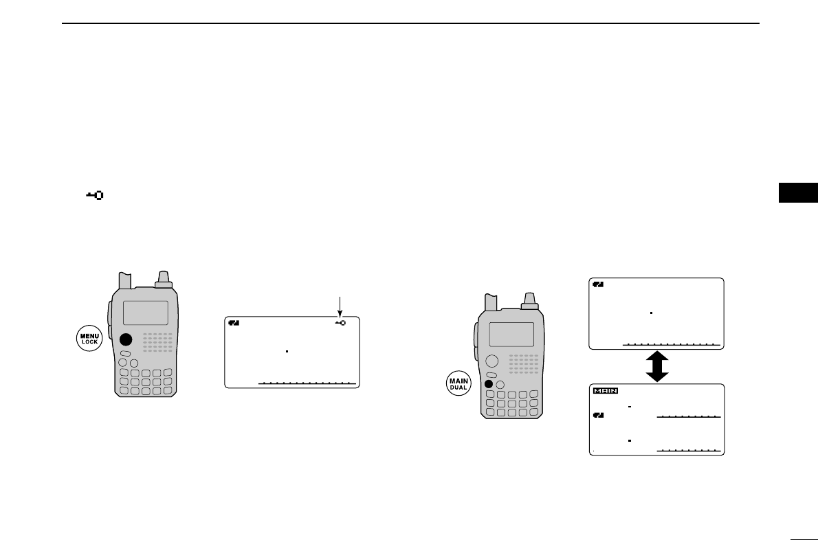
■Lock function
To prevent accidental frequency changes and unnecessary
function access, use the lock function.
➥Push and hold [MENU/LOCK] for 1 sec. to turn the lock
function ON and OFF.
•“ ” appears while the lock function is activated.
•The squelch control and volume control can be used while the
lock function is in use with default setting. Either or both the
squelch control and volume control can also be locked in set
mode. (p. 90)
■Dualwatch operation
Dualwatch operation monitors two frequencies simultane-
ously. The IC-91A/91AD has two independent receiver cir-
cuits as A band and B band (available frequency band or
operating mode are different depending on bands).
DDDualwatch operation
➥Push and hold [MAIN/DUAL] for 1 sec. to turn the dual-
watch operation ON and OFF.
•While dualwatch operation, the display indicates the upper side
as A band and lower side as B band.
DTCSDTCS
DTCSDTCS
W
PSPS
EM
W
PSPS
FM
PRIOPRIO
PRIOPRIO
+DUP
+DUP
FMFM
146010
440000
2525
5050
µ
000
µ
000
A
MemoName
µ
PRIOPRIO WXWX EMREMR
DTCSDTCS
FMFM
LOWLOW
ATTATT
146010
PSKIP
+DUP+DUP
25
000000
A
MemoNameMemoName
µ
PRIOPRIO WXWX EMREMR
DTCSDTCS
FMFM
LOWLOW
ATTATT
146010
PSKIP
+DUP+DUP
25
000000
Appears
26
5BASIC OPERATION
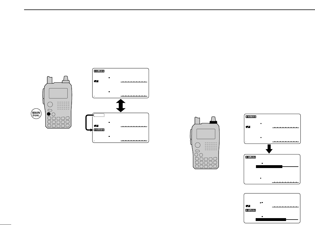
DDMain band selection
➥Push [MAIN/DUAL] to select A band (upper side) or B
band (lower side) as main band (operating band) alter-
nately.
DDSetting audio volume
The audio level for dualwatch operation can be adjusted both
of A band and B band synchronously (default).
This setting can be set to separately for each band in sounds
set mode.
qPush and hold [MAIN/DUAL] for 1 sec. to enter the dual-
watch operation, if necessary.
wRotate
[VOL] to adjust the audio level for the main band.
•If squelch is closed, push and hold [SQL] to verify the audio
level.
•The display shows the volume level while setting.
DTCSDTCS
DTCSDTCS
W
PSPS
EM
W
PSPS
FM
PRIOPRIO
PRIOPRIO
+DUP
+DUP
FMFM
146010
440000
2525
5050
µ
000
µ
000
DTCS
DTCS
W
PS
EMEM
W
PS
PRIO
PRIO
+DUP+DUP
+DUP+DUP
25
75
µ
000000
µ
000000
146010
DTCS
DTCS
W
EMEM
W
PS
PRIO
PRIO
+DUP+DUP
+DUP+DUP
25
75
µ
000000
µ
000000
440000
FMFM
440000
PSPS
FM
146010
VOLVOL
VOLVOL
[VOL]
Setting for A band (upper side)
Setting for B band (lower side)
DTCSDTCS
DTCSDTCS
W
PSPS
EM
W
PSPS
FM
PRIOPRIO
PRIOPRIO
+DUP
+DUP
FMFM
146010
440000
2525
5050
µ
000
µ
000
DTCSDTCS
DTCSDTCS
W
PSPS
EM
W
PSPS
FM
PRIOPRIO
PRIOPRIO
+DUP
+DUP
FMFM
146010
440000
2525
5050
µ
000
µ
000
27
5
BASIC OPERATION
1
2
3
4
5
6
7
8
9
10
11
12
13
14
15
16
17
18
19
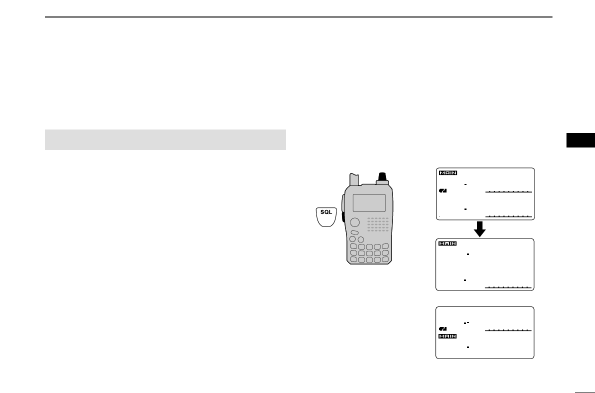
DDVolume setting for dualwatch
The volume setting for dualwatch can be select the adjust-
ment both bands synchronously or each band separately in
sounds set mode.
qEnter “VOLUME SELECT” in sounds set mode. (p. 102)
wRotate [DIAL]†to select “BOTH” or “SEPARATE.”
ePush [5/SKIP](ï)(or [4/DUP](ΩΩ))to return to sounds set
mode, and push [MENU/LOCK] to return to frequency in-
dication.
DDSetting squelch level
qPush and hold [MAIN/DUAL] for 1 sec. to enter the dual-
watch operation, if necessary
wWhile pushing and holding [SQL], rotate [DIAL] to adjust
the main band’s squelch level.
•“LEVEL 1” is loose squelch and “LEVEL 9” is tight squelch.
•“AUTO” indicates automatic level adjustment with a noise pulse
count system.
•“OPEN” indicates continuously open setting.
DTCS
DTCS
W
PS
EMEM
W
PS
PRIO
PRIO
+DUP+DUP
+DUP+DUP
25
75
µ
000000
µ
000000
SQUELCH:AUTO
146010
DTCS
DTCS
W
EMEM
W
PS
PRIO
PRIO
+DUP+DUP
+DUP+DUP
25
75
µ
000000
µ
000000
SQUELCH:LEVEL6
440000
FMFM
440000
PSPS
FM
146010
DTCSDTCS
DTCSDTCS
W
PSPS
EM
W
PSPS
FM
PRIOPRIO
PRIOPRIO
+DUP
+DUP
FMFM
146010
440000
2525
5050
µ
000
µ
000
Setting for A band (Upper)
Setting for B band (Lower)
[DIAL]
MENU screen➪SOUNDS➪VOLUME SELECT
(Push [MENU/LOCK]) (Rotate [DIAL]†, then push [5/SKIP](ï)†.)
†[DIAL] ↔[2/SCAN](∫∫)/[8/TS](√√) [5/SKIP](ï)↔[6/M.N](≈≈)
28
5BASIC OPERATION
■TV channel operation
TV channel operation is available only when TV channels are
programmed using the optional RS-91. (p. 125) Also available
for A band operation only.
DTV channel receiving
qPush [CALL/RX➝CS] several times to select TV chan-
nels.
•“TV” and channel number appear.
wRotate [DIAL] to select the desired channel.
•While pushing and holding [BAND], rotating [DIAL] selects the
all channels including skip channel.
DSkip channel setting
Unwanted channels can be skipped for rapid selection, etc.
qPush [CALL/RX➝CS] several times to select TV chan-
nels.
•“TV” and channel number appear.
wRotate [DIAL] to select the channel to be skipped.
•To clear the skip setting, rotate [DIAL] while pushing and holding
[BAND] to select a skip channel.
ePush and hold [5/SKIP] for 1 sec. to toggle the skip set-
ting ON and OFF.
•“SKIP” appears when the channel is set as skip channel.
DAutomatic TV channel programming
TV channels can be programmed automatically.
qPush [CALL/RX➝CS] sev-
eral times to select TV chan-
nels.
•“TV” and channel number ap-
pear.
wPush [2/SCAN] to start TV
channel programming.
•The programming will automatically stop when scanning all
channels.
TVTV
A
MemoName
µ
PRIOPRIO WXWX EMREMR
DTCSDTCS
WFMWFM
LOWLOW
ATTATT
2ch
PSKIP
+DUP+DUP
25
TVTV
A
MemoName
µ
PRIOPRIO WXWX EMREMR
DTCSDTCS
WFMWFM
LOWLOW
ATTATT
12 ch
PSKIP
+DUP+DUP
25
[DIAL] Appears
TVTV
A
MemoNameMemoName
µ
PRIOPRIO WXWX EMREMR
DTCSDTCS
WFMWFM
LOWLOW
ATTATT
10 ch
PSKIP
+DUP+DUP
25
TV mode indication
Channel indication
[DIAL]
29
6
REPEATER AND DUPLEX OPERATIONS
1
2
3
4
5
6
7
8
9
10
11
12
13
14
15
16
17
18
19
■Repeater operation
When using a repeater, the transmit frequency is shifted from
the receive frequency by the offset frequency. (p. 97) It is con-
venient to program repeater information into memory chan-
nels. (p. 66)
qSet the receive frequency (repeater output frequency).
wSet the shift direction of the transmit frequency. (–DUP or
+DUP; see p. 31 for details.)
•When the auto repeater function is in use (U.S.A. and Korean
versions only), this selection and step eare not necessary.
(p. 32)
ePush and hold [7/DSQ/TONE] for
1 sec. to activate the subaudible
tone encoder, according to re-
peater requirements.
•“TONE” appears.
Refer to p. 113 for tone frequency
settings.
rPush and hold [PTT] to transmit.
•The displayed frequency automati-
cally changes to the transmit frequency (repeater input fre-
quency).
•If “OFF” appears, check the offset frequency or shift direction.
(p. 30)
tRelease [PTT] to receive.
yPush and hold [SQL] to check whether the other station’s
transmit signal can be directly received or not.
U.S.A. and Korean versions:
Auto repeater function uses the settings of the repeater
tone frequency and offset frequency.
A
TONE
FM
145
PSKIP
-DUP
A
TONE
FM
144700
PSKIP
-DUP
300
A
TONETONE
FMFM
145300
-DUP-DUP
“–DUP”or “+DUP” appears.
Station A Station B
Repeater
145.300 MHz
144.700 MHz 144.700 MHz
145.300 MHz
Uplink
Downlink
(transmitting freq.)
(receiving freq.)
30
6REPEATER AND DUPLEX OPERATIONS
DChecking the repeater input signal
The transceiver can check whether the other station’s trans-
mit signal can be received directly or not.
➥Push and hold [SQL] to check whether the other station’s
transmit signal can be directly received or not.
•When the other station’s signal can be directly received, move
to a non-repeater frequency with simplex. (duplex OFF)
DDOff band indication
If the transmit frequency is out of the amateur band, the off
band indication, “OFF,” appears on the display when [PTT] is
pushed. Check the offset frequency or duplex direction in this
case. (p. 31)
U.S.A. and Korean versions:
Auto repeater function uses the setting of the offset fre-
quency.
✔
CONVENIENT!
Tone scan function: When you don’t know the subaudible
tone used for a repeater, the tone scan is convenient for de-
tecting the tone frequency.
➥Push and hold [9/BK/T.SCAN] for 1 sec. to start the tone
scan. See p. 114 for more information.
AOFFOFF
TONETONE
FMFM
PSKIPSKIP
-DUP-DUP
Indication while receiving.
Receives –0.6 MHz shift frequency.
Blinks while pushing and holding [SQL].
A
TONE
FM
145300
PSKIP
-DUP
A
TONE
FM
144700
PSKIP
-DUP
Push and hold
31
6
REPEATER AND DUPLEX OPERATIONS
1
2
3
4
5
6
7
8
9
10
11
12
13
14
15
16
17
18
19
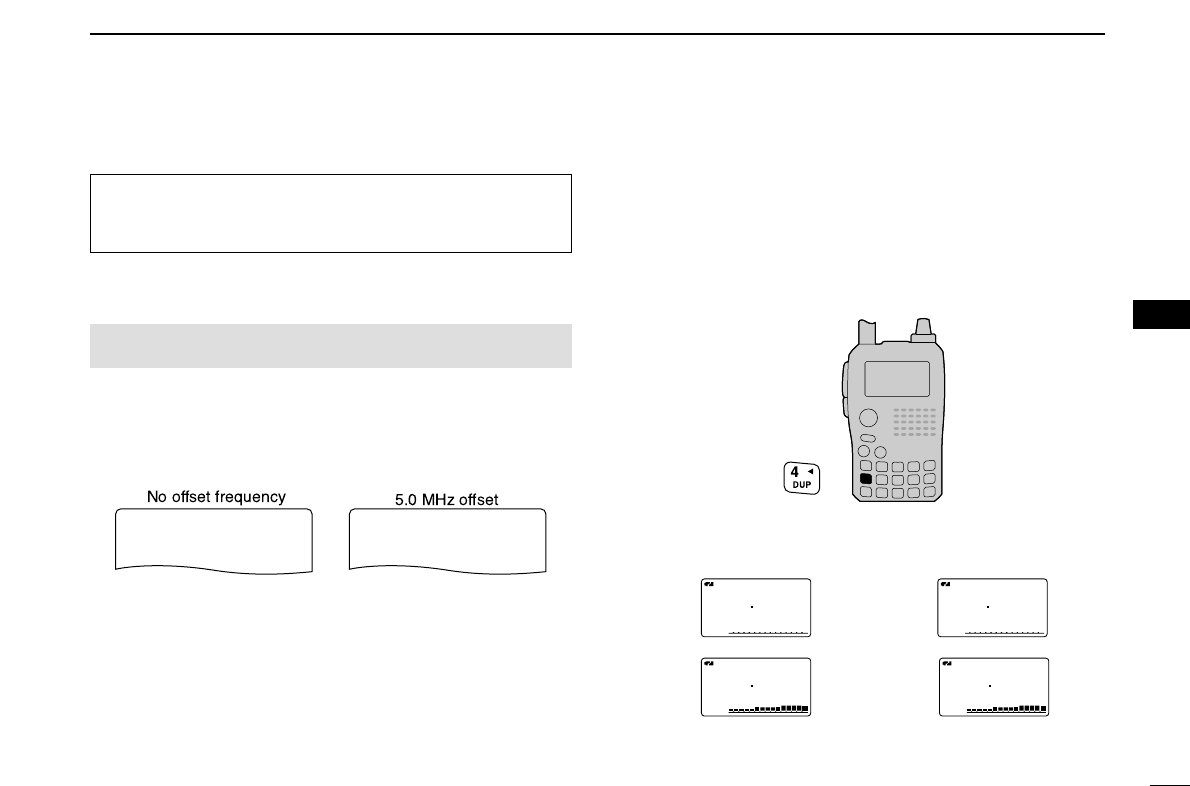
■Duplex operation
DSetting offset frequency
qEnter “OFFSET FREQ” in DUP/TONE… set mode. (p. 97)
wRotate [DIAL]†to set offset frequency.
ePush [5/SKIP](ï)(or [4/DUP](ΩΩ))to return to DUP/TONE…
set mode, and push [MENU/LOCK] to return to frequency
indication.
DSetting duplex direction
➥Push and hold [4/DUP] for 1 sec. to select “–DUP” or
“+DUP”.
•“–DUP” or “+DUP” indicates the transmit frequency for minus
shift or plus shift, respectively.
•When offset frequency is 0.6 MHz.
U.S.A. and Korean versions:
Auto repeater function has priority over the manual duplex
setting. If the frequency changes after setting, the auto re-
peater function may have changed the duplex setting.
–Duplex example +Duplex example
Receiving
Transmitting
A
TONETONE
FMFM
145300
PSKIPSKIP
-DUP-DUP
A
TONETONE
FMFM
144700
PSKIPSKIP
-DUP-DUP
Receiving
Transmitting
A
TONETONE
FMFM
145300
PSKIPSKIP
+DUP+DUP
A
TONETONE
FMFM
145900
PSKIPSKIP
+DUP+DUP
5.000.00 5.000.00
OFFSET FREQ
0.000.00 0.000.00
OFFSET FREQ
MENU screen➪DUP/TONE…➪OFFSET FREQ
(Push [MENU/LOCK]) (Rotate [DIAL]†, then push [5/SKIP] (ï)†.)
Although [DIAL] and [5/SKIP](ï)are used for description
in this section, [2/SCAN](∫∫)/[8/TS](√√)and [6/M.N](≈≈)are
available instead of [DIAL] and [5/SKIP](ï).
†[DIAL] ↔[2/SCAN](∫∫)/[8/TS](√√) [5/SKIP](ï)↔[6/M.N](≈≈)
32
6REPEATER AND DUPLEX OPERATIONS
■Auto repeater function
The U.S.A. and Korean versions automatically activate the re-
peater settings (duplex ON/OFF, duplex direction, tone encoder
ON/OFF) when the operating frequency falls within or outside
of the general repeater output frequency range. The offset
and repeater tone frequencies are not changed by the auto
repeater function, reset these frequencies, if necessary.
DFrequency range and offset direction
•U.S.A. version
•Korean version
qEnter “AUTO RPT” in set mode. (p. 89)
wRotate [DIAL]†to select the auto repeater setting.
• Push to
[U.S.A. version]:
•“RPT1”: Activates duplex only. (default)
•“RPT2”: Activates duplex and tone.
•“OFF”: Auto repeater function is turned OFF.
[Korean version]:
•“ON”: Activates duplex and tone. (default)
•“OFF”: Auto repeater function is turned OFF.
ePush [5/SKIP](ï)(or [4/DUP](ΩΩ))to return to set mode,
and push [MENU/LOCK] to return to frequency indication.
MENU screen➪SET MODE➪AUTO RPT
(Push [MENU/LOCK]) (Rotate [DIAL]†, then push [5/SKIP] (ï)†.)
U.S.A./KOREAN versions only
FREQUENCY RANGE SHIFT DIRECTION
439.000–440.000 MHz “–DUP” appears
FREQUENCY RANGE SHIFT DIRECTION
147.000–147.395 MHz “+DUP” appears
442.000–444.995 MHz “+DUP” appears
447.000–449.995 MHz “–DUP” appears
145.200–145.495 MHz
146.610–146.995 MHz “–DUP” appears

33
6
REPEATER AND DUPLEX OPERATIONS
1
2
3
4
5
6
7
8
9
10
11
12
13
14
15
16
17
18
19
■1750 Hz tone
Some European repeaters require a 1750 Hz tone burst to be
accessed. For such European repeaters, perform the follow-
ing.
•This tone can be use as a ‘Call signal’in countries out of Europe.
qPush and hold [./EMR/DTMF.M](#) for 1 sec. to select
DTMF memory.
wRotate [DIAL]†counter-clockwise until “T-CALL” appears.
ePush [VFO/MHz] to exit DTMF memory.
rSet the receive frequency (repeater output frequency).
tSet the shift direction of the transmit frequency. (–DUP or
+DUP; see p. 31 for details.)
yWhile pushing [PTT], push [SQL] to transmit a 1750 Hz
tone burst signal.
•If “OFF” appears, check the offset frequency or shift direction.
(p. 97)
•The displayed frequency automatically changes to the transmit
frequency (repeater input frequency).
uPush and hold [PTT] to transmit.
iRelease [PTT] to receive.
oPush and hold [SQL] to check whether the other station’s
transmit signal can be received directly or not.
r
T-CALLT-CALL
DTMF MEMORY
r
Ch01Ch01
DTMF MEMORY
†[DIAL] ↔[2/SCAN](∫∫)/[8/TS](√√) [5/SKIP](ï)↔[6/M.N](≈≈)
34
DV MODE OPERATION (Optional UT-121 is required for IC-91A)
7
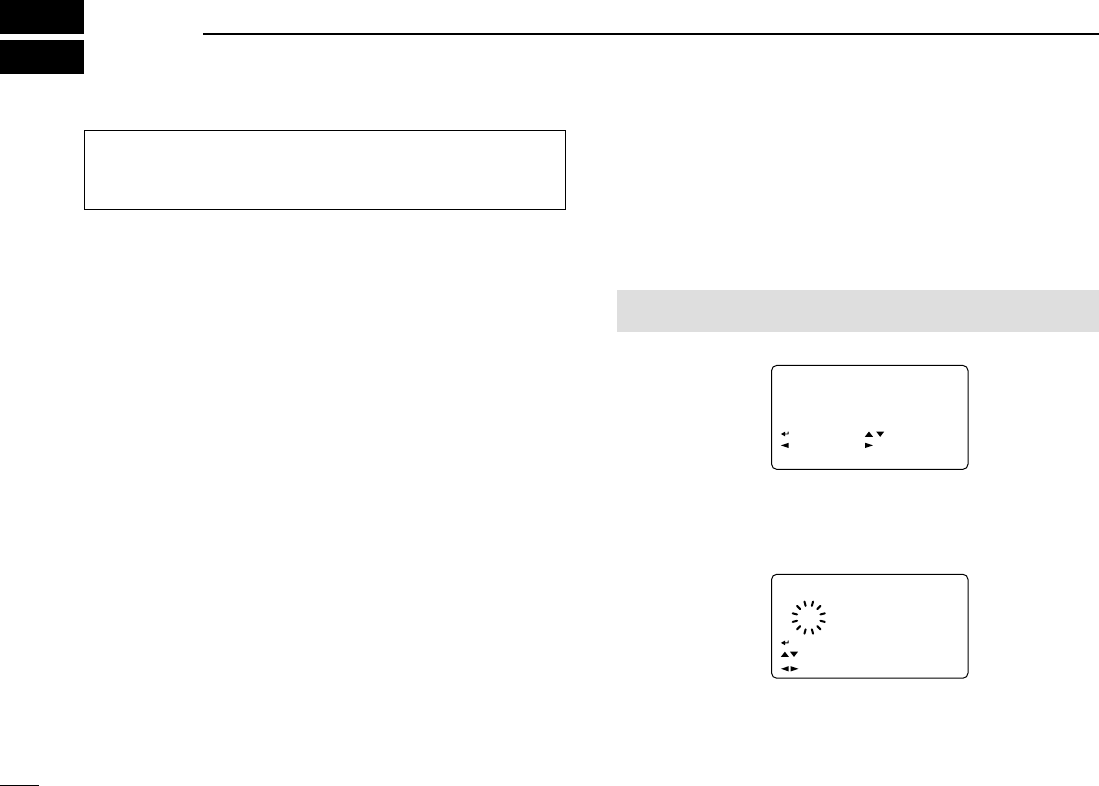
■Digital mode operation
The IC-91A*/91AD can be operated for digital voice mode
and slow-speed data operation for both transmit and receive.
It can also be connected to a GPS receiver (compatible with an
RS-232 output/NMEA format/38400 bps) and transmit/receive po-
sition data.
*The optional UT-121 is required for the IC-91A.
■Call sign programming
Four types of call sign memories are available for your own
call sign “MY CALL SIGN,” other station call sign “YOUR
CALL SIGN,” repeater call sign “RPT1 CALL SIGN” and
“RPT2 CALL SIGN.” “MY CALL SIGN” can store up to 6 call
signs, “YOUR CALL SIGN” can store up to 60 call signs and
“RPT1/2 CALL SIGN” can store up to 60 call signs, and each
call sign can be programmed with up to 8 characters.
DDYour own call sign programming
Your own call sign must be programmed for both digital voice
and slow-speed data communications (including GPS transmis-
sion).
qSelect B band as the main band. (p. 14)
wEnter “MY” in call sign set mode.
•MY CALL SIGN screen is displayed.
eRotate [DIAL]†to select the desired call sign memory,
“M01” to “M06.”
rPush [6/M.N](≈≈)to enter call sign programming mode.
•The 1st digit blinks.
tRotate [DIAL]†to select the desired character or code.
•Push [3/LOW](A/a) to change the character group from “AB” (al-
phabetical characters; capital letters), “12” (numbers) and “/”
(symbols) in sequence.
M01M01
†
/
MY CALL SIGN
r
:SET:SET
:SEL:SEL
:CUR:CUR
CLR:CLRCLR:CLR
A/a:CHARA/a:CHAR
AB
M01M01
/
:SET
:BACK
:SEL
:EDIT
CLR:CLR
MY CALL SIGN
r
MENU screen➪CALL SIGN➪MY
(Push [MENU/LOCK]) (Rotate [DIAL]†, then push [5/SKIP](ï)†.)
Although [DIAL] and [5/SKIP](ï)are used for description
in this section, [2/SCAN](∫∫)/[8/TS](√√)and [6/M.N](≈≈)are
available instead of [DIAL] and [5/SKIP](ï).

35
7
DV MODE OPERATION (Optional UT-121 is required for IC-91A)
7
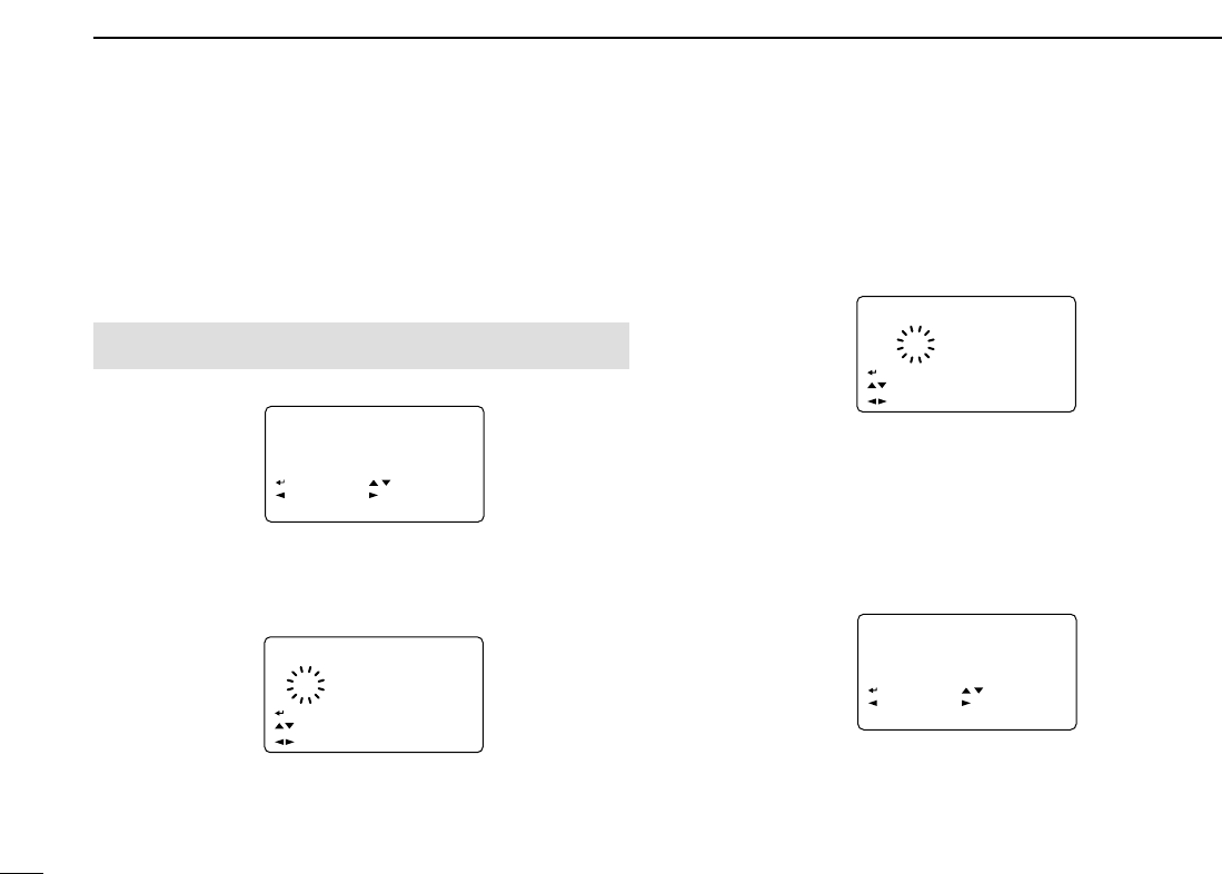
yPush [6/M.N](≈≈)to select 2nd digit, then rotate [DIAL]†to
select the desired character or code.
•Push [6/M.N](≈≈)to move the cursor right; push [4/DUP](ΩΩ)to
move the cursor left.
•2nd digit blinks (1st digit stops blinking).
uRepeat the steps tand yto enter your own call sign.
•Up to a 8-digit of call sign can be set.
•If un-necessary character is entered, push [6/M.N](≈≈)or
[4/DUP](ΩΩ)to select the character, then push [1/SCOPE](CLR)
to erase the selected character, or push and hold
[1/SCOPE](CLR) for 1 sec. to erase following all characters from
the cursor.
•When programming a note (Up to a 4-digit for operating radio
type or area, etc.), go to step !0.
iPush [6/M.N](≈≈)several times to set the cursor beside “/”
indication.
oRepeat steps tto yto program the desired 4-character
note.
!0 Push [5/SKIP](ï)to store the programmed call sign with
note and returns to MY CALL SIGN screen.
!1 Push [MENU/LOCK] to return to frequency indication.
M01M01
MYCALL MYCALL
/IC91 /IC91
:SET
:BACK
:SEL
:EDIT
CLR:CLR
MY CALL SIGN
r
M01M01
M†
/
MY CALL SIGN
r
:SET:SET
:SEL:SEL
:CUR:CUR
CLR:CLRCLR:CLR
A/a:CHARA/a:CHAR
AB
1
2
3
4
5
6
8
9
10
11
12
13
14
15
16
17
18
19
†[DIAL] ↔[2/SCAN](∫∫)/[8/TS](√√) [5/SKIP](ï)↔[6/M.N](≈≈)
36
7DV MODE OPERATION (Optional UT-121 is required for IC-91A)
DDStation call sign programming
Station call sign must be programmed for the specified sta-
tion call as well as repeater operation in both digital voice and
slow-speed data communications.
qSelect B band as the main band. (p. 14)
wEnter “UR” in call sign set mode.
•YOUR CALL SIGN screen is displayed.
eRotate [DIAL]†to select the desired call sign memory,
“U01” to “U60.”
rPush [6/M.N](≈≈)to enter call sign programming mode.
•The 1st digit blinks.
tRotate [DIAL]†to select the desired character or code.
•Push [3/LOW](A/a) to change the character group from “AB” (al-
phabetical characters; capital letters), “12” (numbers) and “/”
(symbols) in sequence.
yPush [6/M.N](≈≈)to select 2nd digit, then rotate [DIAL]†to
select the desired character or code.
•Push [6/M.N](≈≈)to move the cursor right; push [4/DUP](ΩΩ)to
move the cursor left.
•2nd digit blinks (1st digit stops blinking).
uRepeat the steps tand yto enter the desired station call
sign.
•Up to an 8-digit of call sign can be set.
•If un-necessary character is entered, push [6/M.N](≈≈)or
[4/DUP](ΩΩ)to select the character, then push [1/SCOPE](CLR)
to erase the selected character, or push and hold
[1/SCOPE](CLR) for 1 sec. to erase following all characters from
the cursor.
iPush [5/SKIP](ï)to store the programmed call sign with
note and returns to YOUR CALL SIGN screen.
oPush [MENU/LOCK] to return to frequency indication.
U01U01
STATION1 STATION1
:SET
:BACK
:SEL
:EDIT
CLR:CLR
YOUR CALL SIGN
r
U01 AB
S†
:SET:SET
:SEL:SEL
:CUR:CUR
CLR:CLRCLR:CLR
A/a:CHARA/a:CHAR
0:CQ0:CQ
YOUR CALL SIGNYOUR CALL SIGN
r
U01U01 ABAB
†
:SET:SET
:SEL:SEL
:CUR:CUR
CLR:CLRCLR:CLR
A/a:CHARA/a:CHAR
0:CQ0:CQ
YOUR CALL SIGNYOUR CALL SIGN
r
U
CQCQCQ CQCQCQ
:SET
:BACK
:SEL
:EDIT
CLR:CLR
YOUR CALL SIGN
r
MENU screen➪CALL SIGN➪UR
(Push [MENU/LOCK]) (Rotate [DIAL]†, then push [5/SKIP](ï)†.)

37
7
DV MODE OPERATION (Optional UT-121 is required for IC-91A)
7
NOTE: During the call sign programming mode (rto u),
push [0/CQ] to set “CQCQCQ,” and push [0/CQ] again to
return to the previously stored call sign.
✔
For your information
The IC-91A/91AD has call sign edit record function.
This function selects and store into a blank call sign memory
channel automatically when editing a call sign that stored in a
call sign memory, regular memory or call channel with the de-
fault setting. (“FULL” is displayed when all call sign memory is
programmed.)
The edited call sign can be over-written when the setting of
the EDIT RECORD is set to OFF or SELECT. (p. 95)
However, the programmed call sign in regular memory and
call channel must be over-write the regular memory and call
channel themselves. (Temporarily operation is possible.)
†[DIAL] ↔[2/SCAN](∫∫)/[8/TS](√√) [5/SKIP](ï)↔[6/M.N](≈≈)
1
2
3
4
5
6
8
9
10
11
12
13
14
15
16
17
18
19

38
7DV MODE OPERATION (Optional UT-121 is required for IC-91A)
■Digital voice mode operation
qSet the desired frequency in B band. (pgs. 14, 18)
•Select output power, if desired. (p. 24)
wSelect DV mode. (p. 21)
eSet your own call sign for DV operation as follows.
zEnter “MY” in call sign set mode.
xRotate [DIAL]†to select the desired your own call sign
channel (if you have programmed several call signs) then
push [5/SKIP](ï)to set the call sign and return to CALL
SIGN screen.
•See page 34 for your own call sign programming details.
rSet the desired call sign as described in “When calling the
desired station (p. 39)” or “When sending a CQ (p. 39).”
tPush and hold [PTT] to transmit and speak into the micro-
phone at normal voice level.
•Tx/Rx indicator lights red and the RF meter shows the output
power.
yRelease [PTT] to return to receive.
•The other station call sign will be received.
•Received call signs can be stored into the received call record
automatically. See page 93 for details.
NOTE: The digital mode operation is vastly different from
FM mode. One of the differences is in digital mode the
squelch does not function as in FM mode. Changing the
squelch setting will not open it to hear the hiss of “White
Noise.” It only activates for digital squelch functions such
as CSQL (Digital code squelch) or DSQL (Digital call sign
squelch).
UR:UR:
R1:R1:
R2:NOT USE*R2:NOT USE*
MY:MYCALLMY:MYCALL
/IC91 /IC91
CALL SIGN
r
MENU screen➪CALL SIGN➪MY
(Push [MENU/LOCK]) (Rotate [DIAL]†, then push [5/SKIP](ï)†.)

39
7
DV MODE OPERATION (Optional UT-121 is required for IC-91A)
7
DDWhen calling the desired station
Continued instruction from step xon page 38.
cRotate [DIAL]†to select “UR,” then push [5/SKIP](ï)†.
•YOUR CALL SIGN screen is displayed.
vRotate [DIAL]†to select the call sign channel that desired
station’s call sign is programmed.
•See page 36 for station call sign programming details.
bPush [5/SKIP](ï)to set the station’s call sign and return to
CALL SIGN screen.
nPush [MENU/LOCK] to return to frequency indication.
mOperate the instruction steps tand yon page 38.
DDWhen sending a CQ
Continued instruction from step xon page 38.
cRotate [DIAL]†to select “UR,” then push [5/SKIP](ï)†.
•YOUR CALL SIGN screen is displayed.
vRotate [DIAL]†to select the call sign channel that “CQC-
QCQ” is programmed.
Or, select “U” then push [6/M.N](≈≈)and [0/CQ] in se-
quence to set “CQCQCQ.”
bPush [5/SKIP](ï)to set “CQCQCQ” as the call sign and
return to CALL SIGN screen.
nPush [MENU/LOCK] to return to frequency indication.
mOperate the instruction step tand yon page 38.
UR:CQCQCQUR:CQCQCQ
R1:R1:
R2:NOT USE*R2:NOT USE*
MY:MYCALLMY:MYCALL
/IC91 /IC91
CALL SIGN
r
UR:STATION1UR:STATION1
R1:R1:
R2:NOT USE*R2:NOT USE*
MY:MYCALLMY:MYCALL
/IC91 /IC91
CALL SIGN
r
†[DIAL] ↔[2/SCAN](∫∫)/[8/TS](√√) [5/SKIP](ï)↔[6/M.N](≈≈)
1
2
3
4
5
6
8
9
10
11
12
13
14
15
16
17
18
19
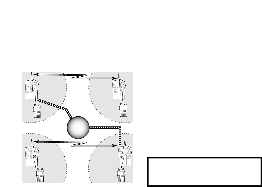
40
7DV MODE OPERATION (Optional UT-121 is required for IC-91A)
■About D-STAR system
In the D-STAR system, repeater linking via a 10 GHz band
backbone and internet network (gateway connection) capa-
bilities are available. This system provides you to with much
wider coverage range during digital voice mode operation.
• D-STAR system outline
For current existing repeater operation, stations that are com-
municating must be in the same repeater’s operating area.
However, in the D-STAR system as in the illustration at left,
the repeaters can be linked via the system repeaters (with a
10 GHz signal). Thus stations A and B can communicate even
though they are in different repeater operating areas.
Also, the D-STAR system repeaters are connectable through
the internet network— gateway connection capability.
For example, when station B uses the gateway connection
station B can communicate with the station C!
By using the gateway connection, long distance communica-
tion like DX operation may be possible with 144 or 440 MHz
digital voice!
In the D-STAR system, an independent repeater’s operating
area is called an Area and a group that linking repeaters via a
10 GHz backbone is called a Zone.
Station
A
Station C Station D
Repeater A
Repeater D
440 MHz
440 MHz
Repeater C
10 GHz
Station
B
Repeater B
10 GHz
440 MHz
440 MHz
Internet
network
Internet
network
About time-out timer function
The IC-91A/91AD has a time-out timer function for digital
repeater operation. The timer limits a continuous transmis-
sion for approx. 10 min. Warning beeps will sound before
30 sec. (approx.) and just before the timer functioning.

41
7
DV MODE OPERATION (Optional UT-121 is required for IC-91A)
7
■Digital repeater operation
Repeater call sign must be programmed for repeater opera-
tion in both digital voice and slow-speed data communica-
tions.
DDRepeater call sign programming
qSelect B band as the main band. (p. 00)
wEnter “R1” or “R2” in call sign set mode. (p. 00)
•RPT1 or RPT2 CALL SIGN screen is displayed.
eRotate [DIAL]†to select the desired call sign memory,
“R01” to “R60.”
rPush [6/M.N](≈≈)to enter call sign programming mode.
•The 1st digit blinks.
tRotate [DIAL]†to select the desired character or code.
•Push [3/LOW](A/a) to change the character group from “AB” (al-
phabetical characters; capital letters), “12” (numbers) and “/”
(symbols) in sequence.
•Set “/” at the 1st digit then set the desired area repeater’s call
sign (in different zone) for CQ call (“/” stands for “CQCQCQ”) in a
different zone operation. (p. 00)
yPush [6/M.N](≈≈)to select 2nd digit, then rotate [DIAL]†to
select the desired character or code.
•Push [6/M.N](≈≈)to move the cursor right; push [4/DUP](ΩΩ)to
move the cursor left.
•2nd digit blinks (1st digit stops blinking).
uRepeat the steps tand yto enter the desired repeater
call sign.
•Up to an 8-digit of call sign can be set.
•Push [7/DSQ/TONE] when setting with the gateway connection
if the set repeater has gateway capability.
•If un-necessary character is entered, push [6/M.N](≈≈)or
[4/DUP](ΩΩ)to select the character, then push [1/SCOPE](CLR)
to erase the selected character, or push and hold
[1/SCOPE](CLR) for 1 sec. to erase following all characters from
the cursor.
iPush [5/SKIP](ï)to store the programmed call sign with
note and returns to RPT1 or RPT2 CALL SIGN screen.
oPush [MENU/LOCK] to return to frequency indication.
R01R01
RPT1AA G RPT1AA G
:SET
:BACK
:SEL
:EDIT
CLR:CLR
RPT1 CALL SIGN
r
MENU screen➪CALL SIGN➪R1/R2
(Push [MENU/LOCK]) (Rotate [DIAL]†, then push [5/SKIP](ï)†.)
†[DIAL] ↔[2/SCAN](∫∫)/[8/TS](√√) [5/SKIP](ï)↔[6/M.N](≈≈)
1
2
3
4
5
6
8
9
10
11
12
13
14
15
16
17
18
19

42
7DV MODE OPERATION (Optional UT-121 is required for IC-91A)
DDRepeater operation in the same zone
qSet the desired repeater’s frequency, offset and shift direc-
tion in B band. (p. 00)
•Select DV mode in advance. (p. 00)
wSet your own call sign. (p. 00)
•See p. 00 for your own call sign programming.
eSet the desired station call sign. (pgs. 00, 00)
•See p. 00 for station call sign programming.
rSet the repeater’s call sign as follows;
zEnter “R1” in call sign set mode.
xRotate [DIAL]†to select the nearest repeater’s call sign.
cPush [5/SKIP](ï)to set the call sign for “R1.”
•Return to CALL SIGN screen.
vRotate [DIAL]†to select “R2” then push [5/SKIP](ï)†.
•RPT2 CALL SIGN screen is displayed.
bRotate [DIAL]†to select the desired repeater’s (in the
same zone) call sign.
•Select “NOT USE✱” when not operating RPT2.
nPush [5/SKIP](ï)to set the call sign for “R2.”
•Return to CALL SIGN screen.
mPush [MENU/LOCK] to return to frequency indication.
tPush [PTT] to transmit; release to receive.
UR:CQCQCQUR:CQCQCQ
R1:RPT1AAR1:RPT1AA
R2:NOT USE*R2:NOT USE*
MY:MYCALLMY:MYCALL
/IC91 /IC91
CALL SIGN
r
MENU screen➪CALL SIGN➪R1
(Push [MENU/LOCK]) (Rotate [DIAL]†, then push [5/SKIP](ï)†.)
†[DIAL] ↔[2/SCAN](∫∫)/[8/TS](√√) [5/SKIP](ï)↔[6/M.N](≈≈)
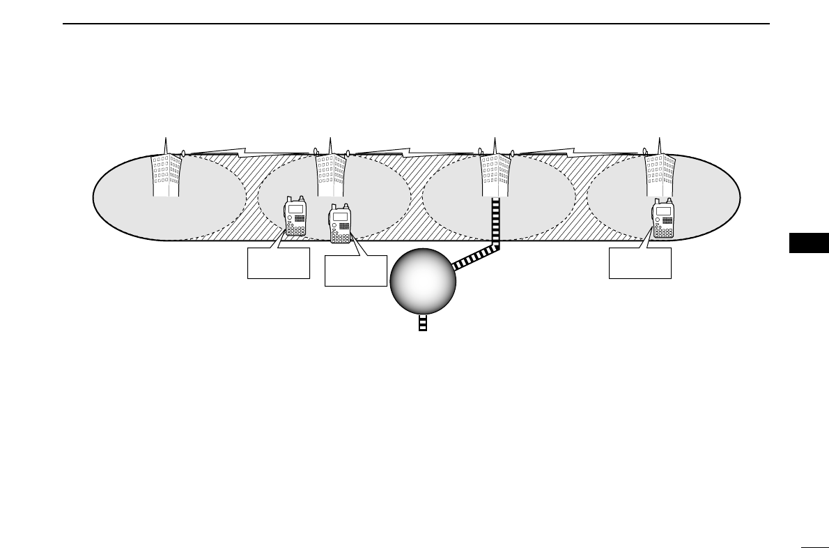
43
7
DV MODE OPERATION (Optional UT-121 is required for IC-91A)
7
Area 1
Zone
to another Zone
• Setting example 1
Repeater 1
: A11111
Area 2 Repeater 2
: A22222
Area 3
(Gateway)
Repeater 3
: A33333
Area 4 Repeater 4
: A44444
✔
What is the area?
The Area is the communication range that is
covered by a local repeater.
The Local repeater is called as an area repeat-
er in the D-STAR® system.
✔
What is the zone?
The Zone is composed of several areas, that
are linked by the 10 GHz microwave signal.
The areas 1 to 4 make up a zone in the exam-
ple above.
Station A
: A2222A Station B
: A2222B
Station C
: A4444C
Internet
network
Internet
network
❑The setting when the Station A is
calling the Station B
UR : A2222B
R1 : A22222
R2 : NOT USEQ
MY : A2222A
❑The setting when the Station A is
making a CQ call in area 1
UR : CQCQCQ
R1 : A22222
R2 : A11111
MY : A2222A
❑The setting when the Station A is
calling the Station C
UR : A4444C
R1 : A22222
R2 : A44444
MY : A2222A
1
2
3
4
5
6
8
9
10
11
12
13
14
15
16
17
18
19

44
7DV MODE OPERATION (Optional UT-121 is required for IC-91A)
DDRepeater operation into another zone
qSet the desired repeater’s frequency, offset and shift direc-
tion in B band. (p. 00)
•Select DV mode in advance.
wSet your own call sign. (p. 00)
•See p. 00 for your own call sign programming.
eSet the desired station call sign. (pgs. 00, 00)
• When making a CQ call
Set the desired repeater’s (in a different zone) call sign that
has “/” symbol at the 1st digit, for the area you want to
make a CQ call, into “UR.”
•See p. 00 for station call sign programming.
rSet the repeater’s call sign as follows;
zEnter “R1” in call sign set mode.
xRotate [DIAL]†to select the nearest repeater’s call sign.
•If the nearest repeater is gateway repeater, select the re-
peater’s call sign with “G” setting at the 8th digit.
cPush [5/SKIP](ï)to set the call sign for “R1.”
•Return to CALL SIGN screen.
vRotate [DIAL]†to select “R2” then push [5/SKIP](ï)†.
bRotate [DIAL]†to select the gateway repeater’s (in the
same zone) call sign.
•The call sign should have “G” setting at the 8th digit.
•When gateway repeater call sign is set in “R1,” select “NOT
USE✱” for “R2” setting.
nPush [5/SKIP](ï)to set the call sign for “R2.”
•Return to CALL SIGN screen.
mPush [MENU/LOCK] to return to frequency indication.
tPush [PTT] to transmit; release to receive.
UR:CQCQCQUR:CQCQCQ
R1:RPT1AAR1:RPT1AA
R2:NOT USE*R2:NOT USE*
MY:MYCALLMY:MYCALL
/IC91 /IC91
CALL SIGN
r
MENU screen➪CALL SIGN➪R1
(Push [MENU/LOCK]) (Rotate [DIAL]†, then push [5/SKIP](ï)†.)
†[DIAL] ↔[2/SCAN](∫∫)/[8/TS](√√) [5/SKIP](ï)↔[6/M.N](≈≈)
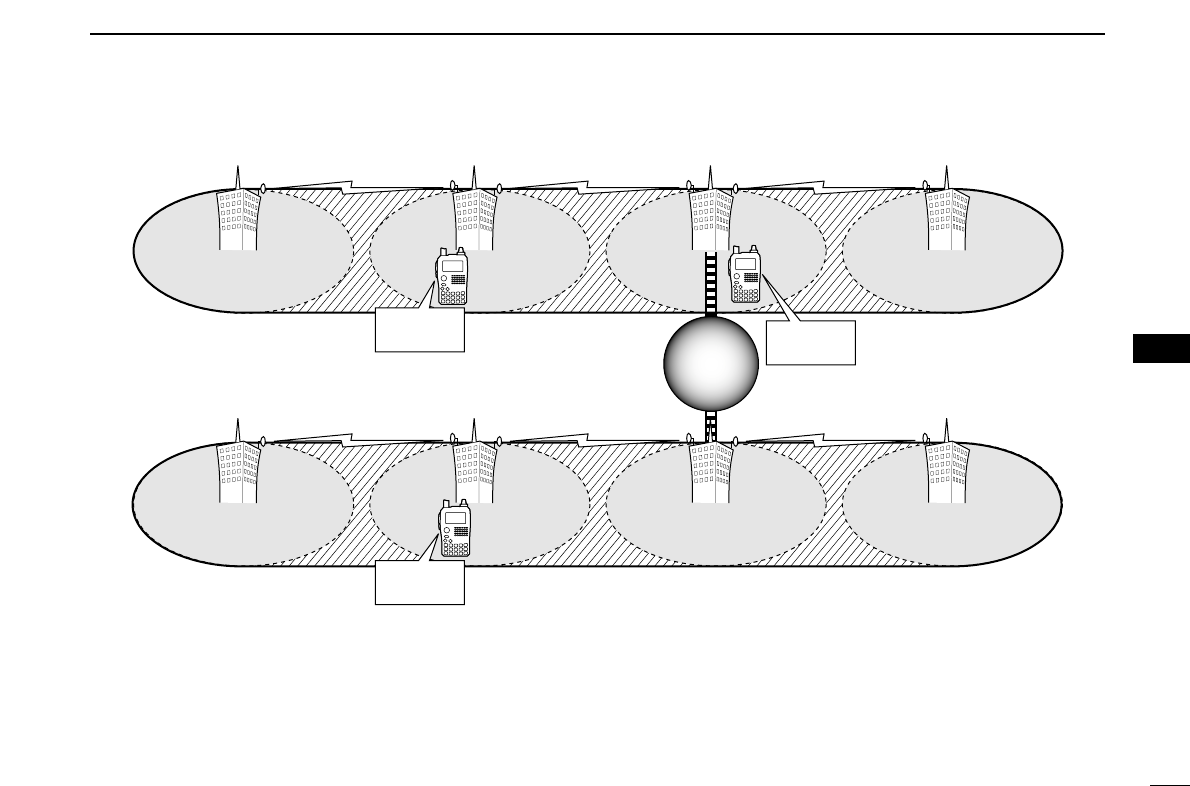
45
7
DV MODE OPERATION (Optional UT-121 is required for IC-91A)
7
Area 1
Zone A
• Setting example 2
Repeater 1
: A11111
Area 2
Repeater 2
: A22222
Area 3
(Gateway)
Repeater 3
: A33333
Repeater 3 3
: A33333
Repeater 3
: A33333 Area 4
Repeater 4
: A44444
Zone B
Area 6
Repeater 6
: B66666
Area 7
(Gateway) Repeater 7
: B77777
Area 8
Repeater 8
: B88888
Area 5 Repeater 5
: B55555
Station C
: B6666C
Station A
: A2222A Station B
: A3333B
Internet
network
Internet
network
❑The setting when the Station A is
calling the Station C
UR : B6666C
R1 : A22222
R2 : A33333 G
MY : A2222A
❑The setting when the Station A is
making a CQ call in area 8
UR : /B88888
R1 : A22222
R2 : A33333 G
MY : A2222A
❑The setting when the Station B is
calling the Station C
UR : B6666C
R1 : A33333 G
R2 : NOT USE✱
MY : A3333B
1
2
3
4
5
6
8
9
10
11
12
13
14
15
16
17
18
19
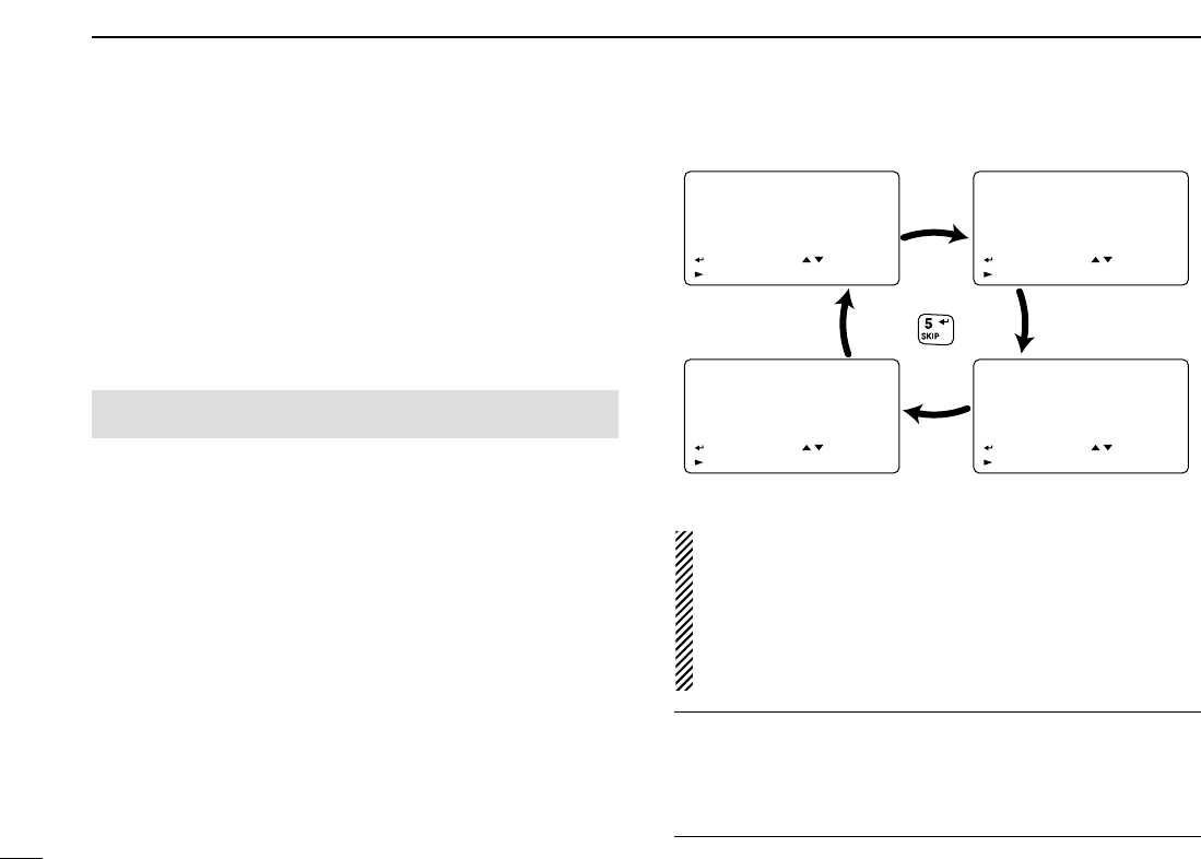
46
7DV MODE OPERATION (Optional UT-121 is required for IC-91A)
■Received call sign
When a call is received in DV mode, the calling station and
using repeater call signs being used can be stored into the
received call record. The stored call signs are viewable in the
following manner.
Up to 20 calls can be recorded.
DDDesired call record indication
qEnter RX call sign set mode.
•RX CALL SIGN screen is displayed.
wRotate [DIAL]†to select the desired record channel.
eTo confirm the received call, push [5/SKIP](ï)several
times to select the desired call sign from CALLER,
CALLED, RXRPT1 and RXRPT2.
CALLER : The station call sign that make a call.
CALLED : The station call sign that called station from the
caller.
RXRPT1 : The repeater call sign near the caller station.
RXRPT2 : The repeater call sign linked from the RXRPT1.
rPush [MENU/LOCK] to return to frequency indication.
NOTE: When a call is received in DV mode during power
save function is activated, the call sign may not be re-
ceived correctly.
This is normal, not a malfunction, because of header of the
call sign cannot be detected during power save.
Turn the power save function OFF (p. 00) if you want to re-
ceive a call sign correctly even in stand-by condition.
✔
For your information
When receive a call, the received call signs, station and re-
peaters, are automatically displayed and scrolled in sequence
at the bottom line of the function display.
This can be turned OFF in display set mode. (p.00)
RX01RX01
CALLER: CALLER:
AAAAAAAAAAAA
/
:CALLED :SEL
:COPY CLR:CLR
RX CALL SIGN
r
RX01RX01
CALLED: CALLED:
CQCQCQCQCQCQ
:RXRPT1 :SEL
:COPY CLR:CLR
RX CALL SIGN
r
RX01RX01
RXRPT2: RXRPT2:
:CALLER :SEL
:COPY CLR:CLR
RX CALL SIGN
r
RX01RX01
RXRPT1: RXRPT1:
:RXRPT2 :SEL
:COPY CLR:CLR
RX CALL SIGN
r
Push
• Station call sign • Called station call sign
• Repeater 1 call sign• Repeater 2 call sign
MENU screen➪RX CALL SIGN
(Push [MENU/LOCK]) (Rotate [DIAL]†, then push [5/SKIP](ï)†.)
†[DIAL] ↔[2/SCAN](∫∫)/[8/TS](√√) [5/SKIP](ï)↔[6/M.N](≈≈)

47
7
DV MODE OPERATION (Optional UT-121 is required for IC-91A)
7
DDOne-touch reply using the call record
The stored call signs in the call record can be set for opera-
tion to reply to the call.
qAfter receiving a call, push and hold [CALL/RX➝CS] for
1 sec.
Or, while pushing and holding [CALL/RX➝CS], rotate
[DIAL] to select the desired call sign record
•Set your own call sign (MY) in advance. (p. 00)
•The call sign stored in “CALLER” is set to “UR,” “RXRPT1” is set
to “R2” and “RXRPT2” is set to “R1.”
•Error beeps sound when a call sign is received incorrectly, and
no call sign is set in this case.
wPush [PTT] to transmit; release to receive.
✔
For your information
When the call that is specifying your own call sign is received,
the station and the using repeater call signs being used can
be set for operation automatically.
•When “Auto Received Call sign Set” (p. 00) is set to ON, the
stored station call sign in “CALLER” is set to “UR” automat-
ically.
•When “Auto Received Repeater Call sign Set” (p. 00) is set
to ON, the stored station call sign in “RXRPT1” is set to “R2”
and “RXRPT2” is set to “R1” automatically.
Important!
The set call signs with the “One-touch reply using the call
record” operation as at below left are for temporary opera-
tion only. Therefore, the set call signs will be erased when
another call sign is set.
•Never saved into a call sign memory.
If you want to save the set call signs, see “Copying the set
call sign contents for temporary operation” (p. 00) for details.
DV
DV
B
439706
PSKIP
PSKIP
-DUP
-DUP
25
AAAAAA
The received call sign is displayed while pushing and
holding [CALL/RX➝CS] when [DIAL] is rotated while
[CALL/RX➝CS] is pushed.
1
2
3
4
5
6
8
9
10
11
12
13
14
15
16
17
18
19
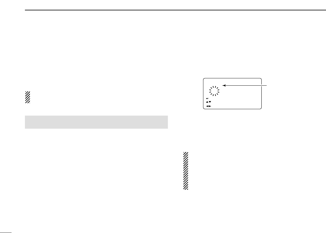
48
7DV MODE OPERATION (Optional UT-121 is required for IC-91A)
■Copying the call sign
DDCopying the call sign memory contents
This function is convenient when saving with additional notes
for areas (for mobile operation) or unit number/initials (if several
transceivers are available), or modifying a part of the current call
sign.
NOTE: Make sure that the “EDIT RECORD” item in DV set
mode is set to “AUTO” or “SELECT” in advance. (p. 00)
qDuring DV mode operation, enter call sign set mode.
•CALL SIGN screen is displayed.
wRotate [DIAL]†to select “UR,” “R1” or “R2” as desired, then
push [5/SKIP](ï)†.
eRotate [DIAL]†to select the desired call sign channel to be
copied.
•M01–M06, U01–U60 and R01–R60 are available.
• When “AUTO” is set to “EDIT RECORD” item
rPush [6/M.N](≈≈)to select the call sign programming mode.
•A blank channel is selected automatically.
•The 1st digit of the selected call sign blinks.
tEdit or modify the selected call sign as described in “DSta-
tion call sign programming” (p. 00) or “DRepeater call sign
programming” (p. 00).
yPush [5/SKIP](ï)to store the edited/modified call sign into
the selected blank channel.
NOTE: The message “FULL” is displayed when no blank
channel is available in station or repeater call sign mem-
ory.
Select the desired call sign channel number as described
in step uof “• When “SELECT” is set to “EDIT RECORD”
item” at right page in this case.
U21 AB
†AAAAAAAAAA
:SET:SET
:SEL:SEL
:CUR:CUR
CLR:CLRCLR:CLR
A/a:CHARA/a:CHAR
0:CQ0:CQ
YOUR CALL SIGNYOUR CALL SIGN
r
A blank channel
number blinks.
MENU screen➪CALL SIGN
(Push [MENU/LOCK]) (Rotate [DIAL]†, then push [5/SKIP](ï)†.)

49
7
DV MODE OPERATION (Optional UT-121 is required for IC-91A)
7
• When “SELECT” is set to “EDIT RECORD” item
rPush [6/M.N](≈≈)to select the call sign programming mode.
•The 1st digit of the selected call sign blinks.
tEdit or modify the selected call sign as described in “DSta-
tion call sign programming” (p. 00) or “DRepeater call sign
programming” (p. 00).
yPush [5/SKIP](ï).
• Call sign channel number blinks.
uRotate [DIAL]†to select the desired call sign channel to
store.
iPush [5/SKIP](ï)to store the edited/modified call sign into
the selected channel.
U21U21 ABAB
AAAAA1 AAAAA1
:SET:SET
:SEL:SEL
:CUR:CUR
CLR:CLRCLR:CLR
A/a:CHARA/a:CHAR
0:CQ0:CQ
YOUR CALL SIGNYOUR CALL SIGN
r
Call sign channel
number bliks.
†[DIAL] ↔[2/SCAN](∫∫)/[8/TS](√√) [5/SKIP](ï)↔[6/M.N](≈≈)
1
2
3
4
5
6
8
9
10
11
12
13
14
15
16
17
18
19
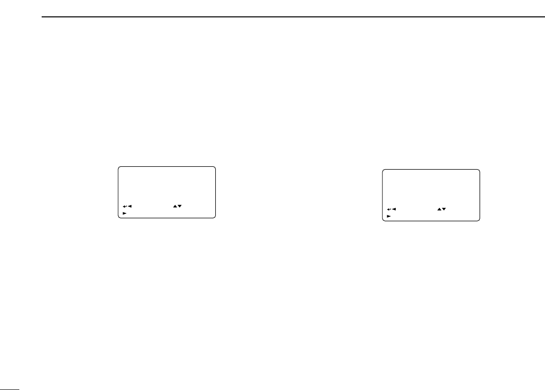
50
7DV MODE OPERATION (Optional UT-121 is required for IC-91A)
DDCopying the call record contents into call sign memory
This is a way to copying the call record contents (“CALLER,”
“RXRPT1” and “RXRPT2”)into call sign memory (“UR,” “R1” and
“R2”)at the same time or individually.
qPerform the steps qto rof “DDesired call record indica-
tion” (p. 00) to select the desired call record or call sign.
wPush [6/M.N](≈≈)to select copy select mode.
•COPY SELECT screen is displayed.
eRotate [DIAL]†to select the desired call sign to be copied
from “ALL,” “RXRPT1” and “RXRPT2.”
•“ALL” selection won’t be appeared when either station or re-
peater call sign memory has no blank channel.
• When “ALL” is selected
➥Push [6/M.N](≈≈)to copy the selected record’s contents
into the appropriate call sign memory.
•Returns to RX CALL SIGN screen automatically.
• When “CALLER,” “RXRPT1” or “RXRPT2” is
selected
z
Push
[6/M.N](≈≈)then r
otate [DIAL]
†
to select the desired
condition of call sign memory channel selection to be
copied to from “AUTO” and “LIST SEL.”
•“AUTO” selection won’t be appeared when the appropriate call
sign memory has no blank channel.
•Go to step rwhen “AUTO” is selected.
xPush [6/M.N](≈≈), then select the desired call sign mem-
ory channel to copy to with [DIAL].
cPush [6/M.N](≈≈)to copy the call sign into the selected
call sign memory.
•Returns to RX CALL SIGN screen automatically.
rPush [MENU/LOCK] to return to frequency indication.
RX01RX01
AUTOAUTO
LIST SELLIST SEL
:BACK:BACK
:LIST:LIST
COPY SELECTCOPY SELECT
:SEL:SEL
r
RX01RX01
ALLALL
:BACK:BACK
:LIST:LIST C:CURRC:CURR
COPY SELECTCOPY SELECT
:SEL:SEL
r
†[DIAL] ↔[2/SCAN](∫∫)/[8/TS](√√) [5/SKIP](ï)↔[6/M.N](≈≈)
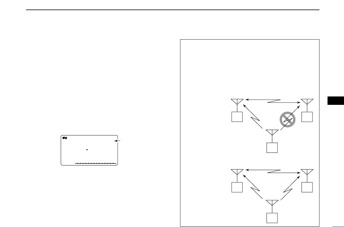
51
7
DV MODE OPERATION (Optional UT-121 is required for IC-91A)
7
■Break-in communication
The break-in function allows you to break into a conversation,
where the two original stations are communicating with call
sign squelch enabled (p. 00).
qWhile receiving an another station’s communication, push
and hold [CALL/RX➝CS] for 1 sec. to set the communi-
cating station’s call sign.
•When a call sign has not been received correctly, error beeps
sound and no call sign is set. Receive the call sign included in a
communicating signal again, or set the call sign manually in this
case.
wPush and hold [9/T.SCAN/BK] for 1 sec. to turn the break-
in function ON.
•“BK” appears.
eWhen both stations are in standby, push [PTT] to transmit
a break-in call.
•Programmed call sign station receives the break-in call as well
as your call sign.
rWait for the reply call from the station who receives the
break-in call.
tAfter receiving the reply call, communicate normally.
yTo cancel the break-in, push and hold [9/T.SCAN/BK] for
1 sec. to turn OFF.
BKBKDVDV
B
LOWLOW
ATTATT
430712
PSKIPPSKIP
50 Appears
• How to use the break-in?
While operating with the call sign squelch (p. 00), the
squelch never opens (no audio sounds) even if a call is re-
ceived, unless your own call sign (“MY”) is specified.
However, when the call including the “BK ON” signal (break-
in call) is received, the squelch will open and audio sounds
even if the call is specified for another station.
Station A Station B
Station C
• Station C calling to Station A with “BK OFF”
Station A Station B
Station C
• Station C calling to Station A with “BK ON”
Station A and B are
communicating us-
ing the call sign
squelch.
Station A and B are
communicating us-
ing the call sign
squelch.
Station B never hears that
Station C is calling Station A.
Station B also hears that Sta-
tion C is calling Station A.
1
2
3
4
5
6
8
9
10
11
12
13
14
15
16
17
18
19
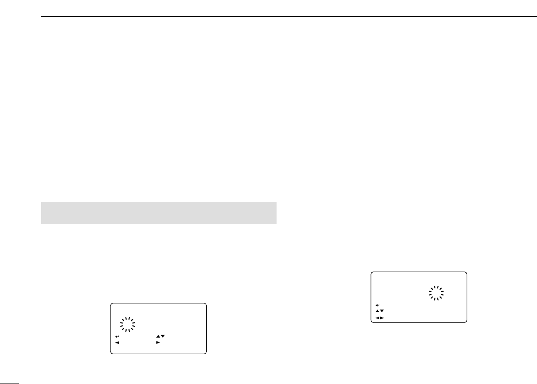
52
7DV MODE OPERATION (Optional UT-121 is required for IC-91A)
■Message operation
DDTX message programming
TX messages are available for up to 6 channels and each
channel can be programmed with a message of up to 20
characters. Available characters are 0to 9, Ato Z(capital let-
ters), ato z(small letters), some symbols and space.
A TX message channel “Ch01” must be programmed, if you
want to use the GPS message. The GPS message is trans-
mitted from Ch01 only.
qEnter “TX MESSAGE” in message/position set mode.
•TX MESSAGE screen is displayed.
wRotate [DIAL]†to select the desired transmit message
channel.
•Ch01 to Ch06 and OFF are available.
•Previously message is displayed if programmed.
ePush [6/M.N](≈≈)to select the message edit condition.
•The 1st digit of the message blinks.
rRotate [DIAL]†to select the desired character or symbol.
•Push [3/LOW](A/a) to change the character group from “AB” (al-
phabetical characters; capital letters), “ab” (alphabetical charac-
ters; small letters), “12” (numbers) and “!”” (symbols) in
sequence.
•If un-necessary character is entered, push [6/M.N](≈≈)or
[4/DUP](ΩΩ)to select the character, then push [1/SCOPE](CLR)
to erase the selected character, or push and hold
[1/SCOPE](CLR) for 1 sec. to erase following all characters from
the cursor.
tPush [6/M.N](≈≈)to select 2nd digit, then rotate [DIAL]†to
select the desired character or code.
•Push [6/M.N](≈≈)to move the cursor right; push [4/DUP](ΩΩ)to
move the cursor left.
•2nd digit blinks (1st digit stops blinking).
yRepeat the steps rand tto enter the desired message.
•Up to 20-character message can be set.
uPush [5/SKIP](ï)to store the message.
iPush [MENU/LOCK] to return to frequency indication.
Ch01Ch01 !''
Hellow!Hellow!
†
:SET:SET
:SEL:SEL
:CUR:CUR
CLR:CLRCLR:CLR
A/a:CHARA/a:CHAR
TX MESSAGETX MESSAGE
r
Ch01Ch01
†
:SET:SET :SEL:SEL
:BACK:BACK
CLR:CLRCLR:CLR
TX MESSAGETX MESSAGE
:EDIT:EDIT
r
MENU screen➪MESSAGE/POSITION➪TX MESSAGE
(Push [MENU/LOCK]) (Rotate [DIAL]†, then push [5/SKIP](ï)†.)
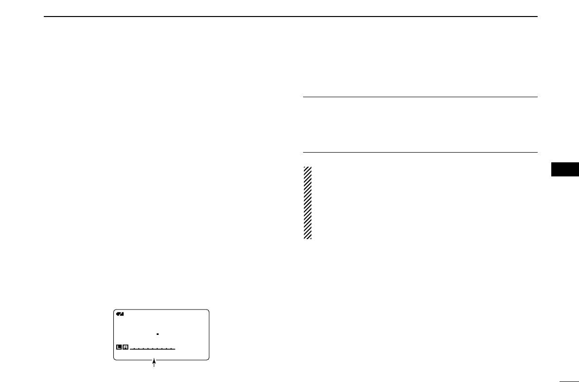
53
7
DV MODE OPERATION (Optional UT-121 is required for IC-91A)
7
DDMessage Transmission
Select the message transmission function ON (Ch01–06) and
OFF. When a message channel is selected, the transceiver
transmits a text message (pre-programmed). (default: OFF)
qSet the operating frequency, call signs and other settings,
such as repeater, as desired in B band. (p. 00)
wPerform the steps qto ein “DTX message program-
ming” as at left.
eRotate [DIAL]†to select the desired message channel.
•“Ch01” to “Ch06” available.
•See left pages for message programming.
rPush [5/SKIP](ï)to set the message for transmission.
tPush [PTT] to transmit the selected message.
•The message is transmitted each time [PTT] is pushed.
•The message is transmitted each 30 sec. automatically during
continuous transmission.
yRelease [PTT] to return to receive.
uWhen the reply call with a message is received, the call
sign and the message scrolls at the bottom of the function
display.
✔
For your information
The automatic received call sign and/or message indication
can be turned OFF in display set mode, if desired.
➥RX CALL SIGN (p. 00)
➥RX MESSAGE (p. 00)
NOTE: Only 1 message can be stored in the IC-
91A/91AD. The received message is cleared once turning
power OFF, or overwritten when another message is re-
ceived.
The transmitted message that includes small caps charac-
ters from the IC-91A/91AD may not be decoded and dis-
played correctly with ID-800H, IC-V82/U82, etc.
DVDV
B
430712
PSKIPPSKIP
50
MSG:Hellow!
Scrolls the received message.
†[DIAL] ↔[2/SCAN](∫∫)/[8/TS](√√) [5/SKIP](ï)↔[6/M.N](≈≈)
1
2
3
4
5
6
8
9
10
11
12
13
14
15
16
17
18
19

54
7DV MODE OPERATION (Optional UT-121 is required for IC-91A)
DDRX message indication
The received message can also be checked in DV set mode.
qSelect “RX MESSAGE” in message/position set mode.
•The received message is displayed in RX MESSAGE screen.
wRotate [DIAL] or push [8/TS](√√)to display the station call
sign.
ePush [5/SKIP](ï)or [4/DUP](ΩΩ)to return to MES-
SAGE/POSITION screen.
rPush [MENU/LOCK] to return to frequency indication.
■Automatic reply function
The automatic reply function replies to the call that specified
your own call sign is received, and the calling station call sign
is automatically set to reply.
2 types of replying method are available— one is making a
reply call with your own call sign, and other one is making a
reply call with reply voice audio that has been recorded in DV
voice memory.
DDAutomatic reply function setting
qEnter “AUTO REPLY” in DV set mode.
•AUTO REPLY screen is displayed.
wRotate [DIAL]†to select the desired reply condition.
OFF : Deactivate the automatic reply function. (default)
ON : Reply to the call with your own call sign.
VOICE : Reply to the call with the recorded voice memory.
ePush [5/SKIP](ï).
•Returns to DV SET MODE screen automatically.
rPush [MENU/LOCK] to return to frequency indication.
OFFOFF
ONON
VOICEVOICE
AUTO REPLY
r
MENU screen➪DV SET MODE➪AUTO REPLY
(Push [MENU/LOCK]) (Rotate [DIAL]†, then push [5/SKIP](ï)†.)
CALLER:CALLER:
BBBBBB BBBBBB
/
:MSG:MSG
:BACK:BACK
RX MESSAGERX MESSAGE
r
MESSAGE:MESSAGE:
Hellow!Hellow!
:CALLER:CALLER
:BACK:BACK
RX MESSAGERX MESSAGE
r
MENU screen➪MESSAGE/POSITION➪RX MESSAGE
(Push [MENU/LOCK]) (Rotate [DIAL]†, then push [5/SKIP](ï)†.)

55
7
DV MODE OPERATION (Optional UT-121 is required for IC-91A)
7
DDVoice memory recording for automatic reply
qEnter “RELY VOICE” in DV voice memo set mode.
•REPLY VOICE screen is displayed.
wWhile pushing and holding [PTT], speak into the micro-
phone.
•Up to 10 second message is recordable.
•The recording stops after 10 second or when [PTT] is released.
ePush [4/DUP](Ω)to return to DV VOICE MEMO screen.
rPush [MENU/LOCK] to return to frequency indication.
DDPlay-back or erase the voice memory
qPush [MENU/LOCK] to select menu mode indication.
wRotate [DIAL]†to select “DV VOICE MEMO,” then push
[5/SKIP](ï)†.
eRotate [DIAL]†to select “REPLY VOICE,” then push
[5/SKIP](ï)†.
•REPLY VOICE screen is displayed.
rTo play-back the recorded voice memory, push
[5/SKIP](ï).
•Push [5/SKIP](ï)again to pause, push [6/M.N](≈≈)to cancel the
play-back.
tTo erase the recorded voice memory, push and hold
[1/SCOPE](CLR) for 1 sec.
REPLY VREPLY V
PTT:PTT:
●
:BACK:BACK CLR:CLRCLR:CLR
REPLY VOICEREPLY VOICE
:
r
MENU screen➪DV VOICE MEMO➪REPLY VOICE
(Push [MENU/LOCK]) (Rotate [DIAL]†, then push [5/SKIP](ï)†.)
IMPORTANT!
Deactivate the dualwatch function and set minimum [VOL]
level when recording the DV voice memo.
Otherwise the received audio or unwanted noise from A
band is also recorded into the voice memory.
†[DIAL] ↔[2/SCAN](∫∫)/[8/TS](√√) [5/SKIP](ï)↔[6/M.N](≈≈)
1
2
3
4
5
6
8
9
10
11
12
13
14
15
16
17
18
19
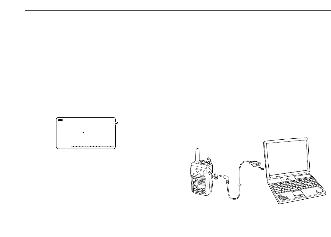
56
7DV MODE OPERATION (Optional UT-121 is required for IC-91A)
■EMR communication
The EMR communication mode is available for digital mode
operation. In the EMR communication mode, no call sign set-
ting is necessary. When an EMR communication mode sig-
nal is received, the audio (voice) will be sound in the specified
level even the volume setting level is set to minimum level.
qSet the desired frequency in 144 or 440 MHz band then
push and hold [•/EMR/DTMF] until 3 short and 1 long
beeps sound to turn the EMR setting ON.
•“EMR” appears
wOperate the transceiver normal way.
eTo cancel the EMR communication mode, push and hold
[•/EMR/DTMF] for 1 sec. to turn OFF.
■
Slow-speed data communication
In addition to the digital voice communication, a slow-speed
data communication is available.
The optional OPC-1529
DATA COMMUNICATION CABLE
and a
slow-speed data communication application (purchase locally)
are required additionally.
The optional RS-91
REMOTE CONTROL SOFTWARE
(OPC-1529
supplied) also includes a slow-speed data communication ca-
pability.
DDConnection
Connect the transceiver to your PC using with the optional
OPC-1529 as illustrated below.
OPC-1529
(optional)
to [DATA]
jack to
RS-232C
EMREMRDVDV
B
430712
PSKIPPSKIP
50 Appears

57
7
DV MODE OPERATION (Optional UT-121 is required for IC-91A)
7
DDSlow-speed data communication application
setting
Set the slow-speed data communication application as fol-
lows.
•Port : The same COM port number as IC-
91A/91AD’s
•Baud rate : 38.4 kbps (fixed value)
•Data : 8 bit
•Parity : None
•Stop : 1 bit
•Flow control : Xon/Xoff
DDSlow-speed data communication operation
qSet your own, station call signs, etc. as described in “■
Digital voice mode operation” (p. 00) and “■Digital repeater
operation” (p. 00).
wRefer to the instructions of the slow-speed data communi-
cation application.
ePush and hold [PTT] to transmit.
•The set data is transmitted with your voice audio.
•Automatic transmission, transmits when text data is input into
buffer, capability is available. See right page for details.
rRelease [PTT] to return to receive.
DDTransmission condition setting
qEnter “DV DATA TX” in DV set mode.
wRotate [DIAL]†to select “PTT” or “AUTO.”
ePush [5/SKIP](ï)†to set the automatic data transmission,
and push [MENU/LOCK] to return to frequency indication.
MENU screen➪DV SET MODE➪DV DATA TX
(Push [MENU/LOCK]) (Rotate [DIAL]†, then push [5/SKIP](ï)†.)
†[DIAL] ↔[2/SCAN](∫∫)/[8/TS](√√) [5/SKIP](ï)↔[6/M.N](≈≈)
1
2
3
4
5
6
8
9
10
11
12
13
14
15
16
17
18
19
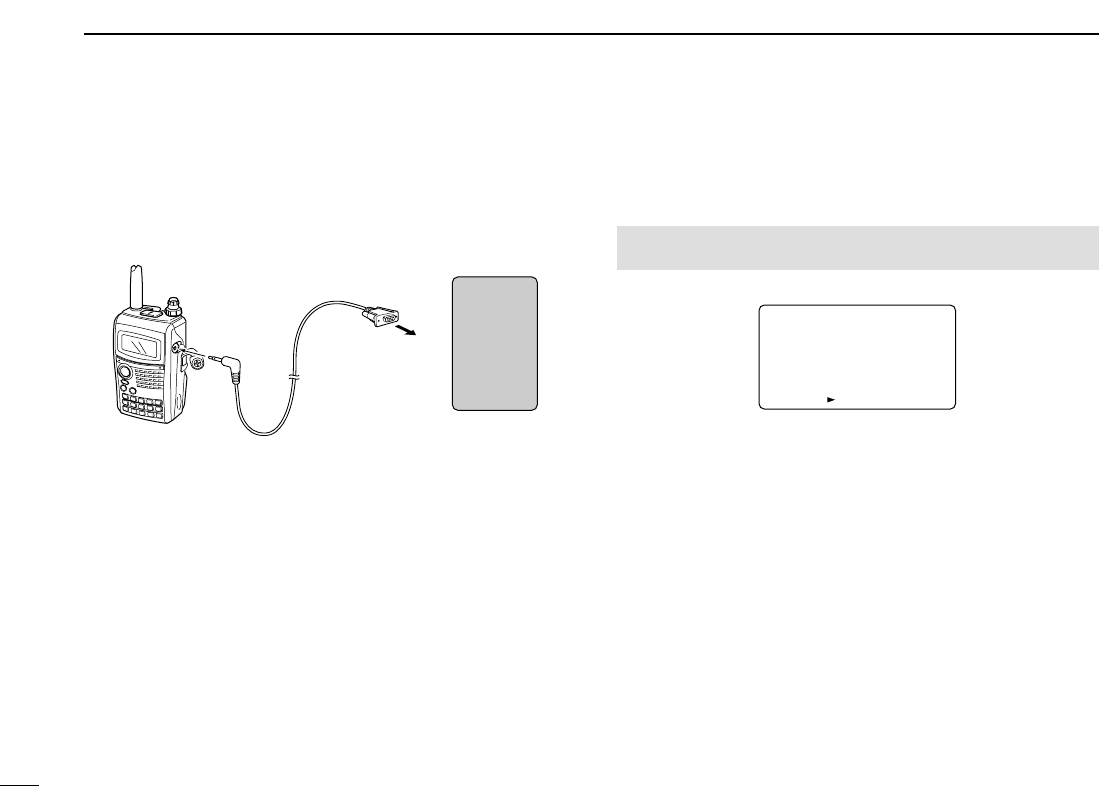
58
7DV MODE OPERATION (Optional UT-121 is required for IC-91A)
■GPS operation
A GPS receiver (RS-232C output/NMEA format) can be con-
nected to [DATA] socket of the IC-91A/91AD to indicate the
current position (Latitude and Longitude). The position data can
also be transmitted with a message to another station.
DDSentence formatter setting
qEnter “GPS MODE” in DV set mode.
•GPS MODE screen is displayed.
wRotate [DIAL]†to select “ON.”
ePush [5/SKIP](ï)†to select GPS SENTENCE screen.
rRotate [DIAL]†to select the desired GPS sentence, then
push [5/SKIP](ï).
•A total 5 sentences, RMC, GGA, GLL, GSA and VTG are avail-
able.
tRotate [DIAL]†to turn the sentence usage ON and OFF.
yPush [5/SKIP](ï)to set and return to GPS SENTENCE
screen.
uRepeat the steps rto yto set another GPS sentence
usage.
•Up to 3 GPS sentences are usable at the same time.
iPush [MENU/LOCK] to return to frequency indication.
OFF
ON
GPS MODEGPS MODE
:SENTENCE:SENTENCE
r
MENU screen➪DV SET MODE➪GPS MODE
(Push [MENU/LOCK]) (Rotate [DIAL]†, then push [5/SKIP](ï)†.)
OPC-1529
(optional)
to [DATA]
jack to RS-232C port
(cross converter
is required)
GPS
receiver
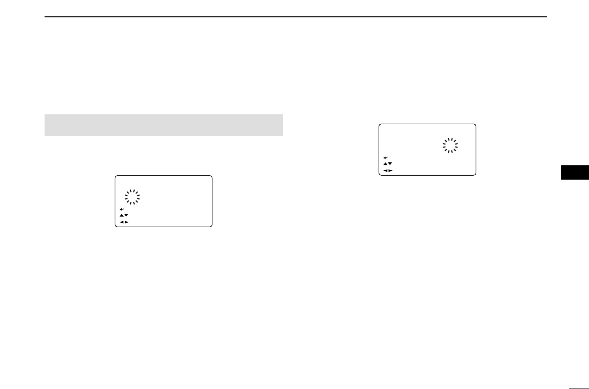
59
7
DV MODE OPERATION (Optional UT-121 is required for IC-91A)
7
DDGPS message programming
qEnter “GPS” in message/position set mode.
•GPS MESSAGE screen is displayed.
wPush [6/M.N](≈≈)to select the message edit condition.
•The 1st digit of the message blinks.
eRotate [DIAL]†to select the desired character or symbol.
•Push [3/LOW](A/a) to change the character group from “AB” (al-
phabetical characters; capital letters), “ab” (alphabetical charac-
ters; small letters), “12” (numbers) and “!”” (symbols) in
sequence.
rPush [6/M.N](≈≈)to select 2nd digit, then rotate [DIAL]†to
select the desired character or code.
•Push [6/M.N](≈≈)to move the cursor right; push [4/DUP](ΩΩ)to
move the cursor left.
•2nd digit blinks (1st digit stops blinking).
tRepeat the steps rand tto enter the desired message.
•Up to 20-character message can be set.
yPush [5/SKIP](ï)to store the message.
uPush [MENU/LOCK] to return to frequency indication.
DATA:DATA: AB
Hellow!Hellow!
†
:SET:SET
:SEL:SEL
:CUR:CUR
CLR:CLRCLR:CLR
GPS MESSAGEGPS MESSAGE
A/a:CHARA/a:CHAR
r
DATA:DATA: ABAB
†
:SET:SET
:SEL:SEL
:CUR:CUR
CLR:CLRCLR:CLR
GPS MESSAGEGPS MESSAGE
A/a:CHARA/a:CHAR
r
MENU screen➪MESSAGE/POSITION➪GPS
(Push [MENU/LOCK]) (Rotate [DIAL]†, then push [5/SKIP](ï)†.)
†[DIAL] ↔[2/SCAN](∫∫)/[8/TS](√√) [5/SKIP](ï)↔[6/M.N](≈≈)
1
2
3
4
5
6
8
9
10
11
12
13
14
15
16
17
18
19

60
7DV MODE OPERATION (Optional UT-121 is required for IC-91A)
DDGPS message automatic transmission
qEnter “GPS AUTO TX” in DV set mode.
•GPS AUTO RX screen is displayed.
wRotate [DIAL]†to select the desired position data transmit-
ting interval from 5 sec., 10 sec., 30 sec., 1 min., 3 min.,
5 min., 10 min., 30 min. and OFF.
•The position data won’t be transmitted when OFF is selected, the
data is transmitted in each 5 sec., 10 sec., 30 sec., 1 min.,
3 min., 5 min., 10 min. and 30 min. when the appropriate setting
is selected.
•The GPS message is also transmitted if programmed.
ePush [5/SKIP](ï)to set the time interval and return to DV
SET MODE screen.
rPush [MENU/LOCK] to return to frequency indication.
DDPosition indication
qEnter “POSITION” in message/position set mode.
•GPS POSITION screen is displayed.
wRotate [DIAL]†to select the received position data indica-
tion.
ePush [5/SKIP](ï)to return to MESSAGE/POSITION
screen.
rPush [MENU/LOCK] to return to frequency indication.
MY POSITION
GPS POSITIONGPS POSITION
r
34.56.789 N34.56.789 N
123.45.678 E123.45.678 E
:RX POS:RX POS
:BACK:BACK
MENU screen➪MESSAGE/POSITION➪POSITION
(Push [MENU/LOCK]) (Rotate [DIAL]†, then push [5/SKIP](ï)†.)
OFF
5SEC5SEC
10SEC10SEC
30SEC30SEC
1MIN1MIN
GPS AUTO TXGPS AUTO TX
r
MENU screen➪DV SET MODE➪GPS AUTO TX
(Push [MENU/LOCK]) (Rotate [DIAL]†, then push [5/SKIP](ï)†.)

61
7
DV MODE OPERATION (Optional UT-121 is required for IC-91A)
1
2
3
4
5
6
7
8
9
10
11
12
13
14
15
16
17
18
19
DDReceived GPS message indication
qEnter “RX GPS” in message/position set mode.
•RX GPS MESSAGE screen is displayed.
wPush [5/SKIP](ï)to return to MESSAGE/POSITION
screen.
ePush [MENU/LOCK] to return to frequency indication.
DATA:DATA:
Call from Call from
Osaka! Osaka!
:BACK:BACK
RX GPS MESSAGERX GPS MESSAGE
r
MENU screen➪MESSAGE/POSITION➪RX GPS
(Push [MENU/LOCK]) (Rotate [DIAL]†, then push [5/SKIP](ï)†.)
†[DIAL] ↔[2/SCAN](∫∫)/[8/TS](√√) [5/SKIP](ï)↔[6/M.N](≈≈)
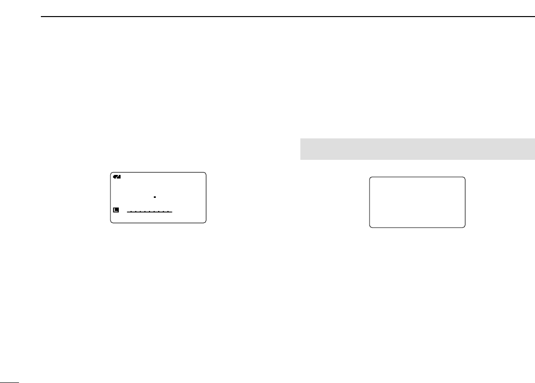
62
7DV MODE OPERATION (Optional UT-121 is required for IC-91A)
■Other functions for DV mode operation
DDDV voice memory
The IC-91A/91AD has a DV voice memory that records a total
30 second (approx.) of received audio.
The DV voice memory is divided into 2 tracks, 15 seconds
each in a track, with the default setting.
◆Recording received audio
qWhile receiving a DV signal, push [REC/MODE].
wRotate [DIAL] to select the desired track.
•“✱” is displayed beside the track number when the selected track
has been recorded.
ePush [REC/MODE] to start recording.
•Track counter (bar meter) is displayed during record.
•The recording is paused automatically when the DV signal is in-
terrupted or when DV audio synchronous signal cannot be re-
ceived correctly. Re-starts the recording when DV audio
synchronous signal is received correctly.
rPush [REC/MODE] again to stop recording.
•The recording is stops automatically even the track becomes full.
◆Track size setting
The track size can be changed with the following instruction.
qEnter “TRACK SIZE” in DV voice memo set mode.
•TRACK SIZE screen is displayed
wRotate [DIAL]†to select the desired track size.
10S/3TRACK : Makes 3 tracks and 10 second audio can
be recorded in each track.
15S/2TRACK : Makes 2 tracks and 15 second audio can
be recorded in each track.
30S/1TRACK : Makes 1 track only and 30 second audio
can be recorded in a track.
ePush [5/SKIP](ï)to set the track size and return to DV
VOICE MEMO screen.
rPush [MENU/LOCK] to return to frequency indication.
10S/3TRACK10S/3TRACK
15S/2TRACK15S/2TRACK
30S/1TRACK30S/1TRACK
TRACK SIZETRACK SIZE
r
MENU screen➪DV VOICE MEMO➪TRACK SIZE
(Push [MENU/LOCK]) (Rotate [DIAL]†, then push [5/SKIP](ï)†.)
DVDV
B
440012
PSKIPPSKIP
50
qREC TRACK:2

63
7
DV MODE OPERATION (Optional UT-121 is required for IC-91A)
1
2
3
4
5
6
7
8
9
10
11
12
13
14
15
16
17
18
19
◆Playing-back and erasing the recorded audio
qEnter “TRACK” in DV voice memo set mode.
•TRACK screen is displayed
wRotate [DIAL]†to select the desired audio track to be play-
back or erased.
•“✱” is displayed beside the track number when the selected track
has been recorded.
ePush [5/SKIP](ï)to play-back the recorded audio.
•Push [5/SKIP](ï)again to pause, push [6/M.N](≈≈)to stop play-
back.
rPush and hold [1/SCOPE](CLR) for 1 sec. to erase the
recorded audio.
tPush [4/DUP](ΩΩ)to return to DV VOICE MEMO screen.
yPush [MENU/LOCK] to return to frequency indication.
DDDV automatic detect
The “DV” mode indicator blinks when other than DV mode
signal is received during DV mode operation.
The IC-91A/91AD has DV automatic detection that selects
and monitors in FM mode when other than DV mode signal is
received.
qEnter “AUTO DETECT” in DV set mode.
wRotate [DIAL]†to turn the DV automatic detect function ON
and OFF.
OFF : “DV” mode indicator blinks, however the trans-
ceiver receives in DV mode even other than DV
mode signal is received.
ON : “DV” mode indicator blinks and the transceiver
monitors the signal in FM mode.
ePush [5/SKIP](ï)to return to DV SET MODE screen
rPush [MENU/LOCK] to return to frequency indication.
NOTE: The received FM audio may be distorted when re-
ceiving an FM signal with DV automatic detect function.
MENU screen➪DV SET MODE➪AUTO DETECT
(Push [MENU/LOCK]) (Rotate [DIAL]†, then push [5/SKIP](ï)†.)
TRACK:1TRACK:1 *
::SEL:SEL
:BACK:BACK CLR:CLRCLR:CLR
TRACKTRACK
r
MENU screen➪DV VOICE MEMO➪TRACK
(Push [MENU/LOCK]) (Rotate [DIAL]†, then push [5/SKIP](ï)†.)
†[DIAL] ↔[2/SCAN](∫∫)/[8/TS](√√) [5/SKIP](ï)↔[6/M.N](≈≈)
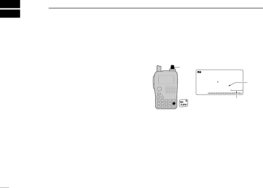
64
MEMORY/CALL CHANNELS
8
■General description
The IC-91A/91AD has 850 memory channels in A band, 450
memory channels in B band, and 2 call channels in each
bands. Memory channels in each bands including 50 scan
edge memory channels (25 pairs) for storage of often-used
frequencies, respectively.
And a total of 26 memory banks, A to Z, are available in each
bands for storing groups of frequencies, etc. Up to 100 chan-
nels can be assigned into a bank.
DDMemory channel contents
The following information can be programmed into memory
channels:
•Operating frequency (p. ??)
•Operating mode (p. ??)
•Duplex direction (+DUP or –DUP) with an offset fre-
quency (pgs. ??, ??)
•Subaudible tone encoder (p. ??), tone squelch or DTCS
squelch ON/OFF (p. ??)
•Subaudible tone frequency (p. ??), tone squelch fre-
quency or DTCS code with polarity (pgs. ??, ??)
•Scan skip information (p. ??).
•Memory bank (p. ??)
•Memory name (p. ??)
•Tuning step (p. ??)
•Call sign squelch or Digital code squelch* (p. ??)
•Your call sign* (p. ??)
•RPT1/RPT2 call sign* (p. ??)
*Available for B band operation only.
■Selecting a memory channel
DDUsing [DIAL]— Programmed channels
qPush [MR/S.MW] to select memory mode.
wRotate [DIAL] to select the desired memory channel.
•Only programmed channels are displayed.
DDUsing [DIAL]— All channels
qPush [MR/S.MW] to select memory mode.
wPush and hold [MR/S.MW] for 1 sec. to enter select mem-
ory write mode.
•1 short and 1 long beep sound.
•“
µµ” indicator blinks.
eRotate [DIAL] to select the desired memory channel.
•All channels are displayed.
[DIAL]
A
µ
FMFM
146010
000000
Appears
Rotate [DIAL] to select
the memory channel.
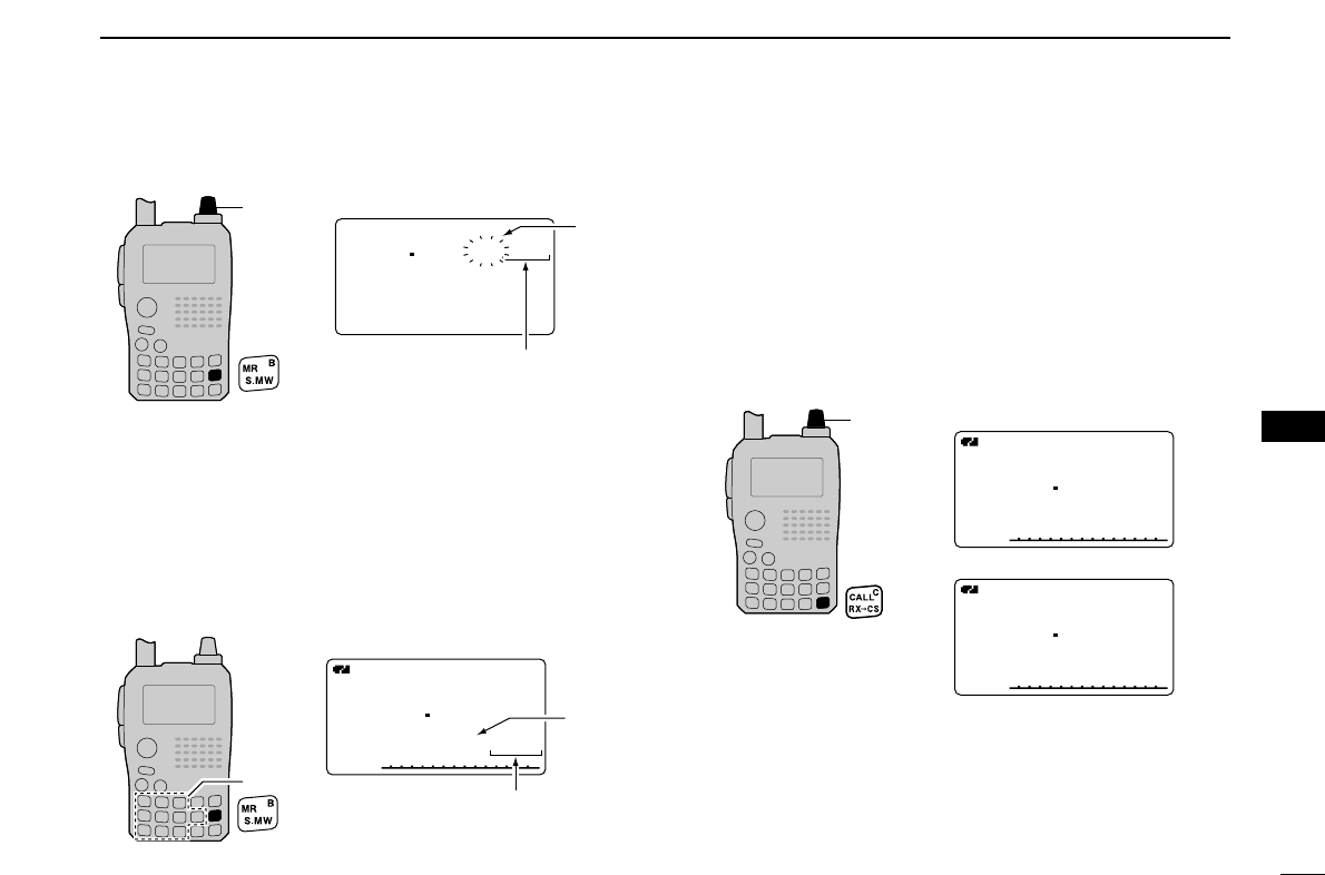
65
8
MEMORY/CALL CHANNELS
1
2
3
4
5
6
7
8
9
10
11
12
13
14
15
16
17
18
19
DDUsing the KEYPAD
qPush [MR/S.MW] to select memory mode.
wPush the KEYPAD to enter 3 digits to select the desired
memory channel.
•The blank channels are also selectable.
• Example— selecting memory channel “25”
Push [MR/S.MW] then push [0], [2], [5].
■Selecting a call channel
qPush [CALL/RX➝CS] to select call channel mode.
•Pushing [CALL/RX➝CS] toggles call, TV* and weather†chan-
nels.
wRotate [DIAL] to select the desired call channel.
•“C0” and “C1” are selectable.
* Available only when the TV channel frequencies are pro-
grammed with the optional RS-91 and A band is selected.
†USA version only.
[DIAL]
A
FMFM
440000
C1C1
A
FMFM
146010
C0C0
VHF band call channel
UHF band call channel
Appears
A
µ
FMFM
145600
025025
The entered memory
channel is selected.
KEYPAD
[DIAL]
146010
BANK :----
MNAME:
SKIP :OFF
FMFM
r
µ
000
Blinks
Rotate [DIAL] to select
the memory channel.
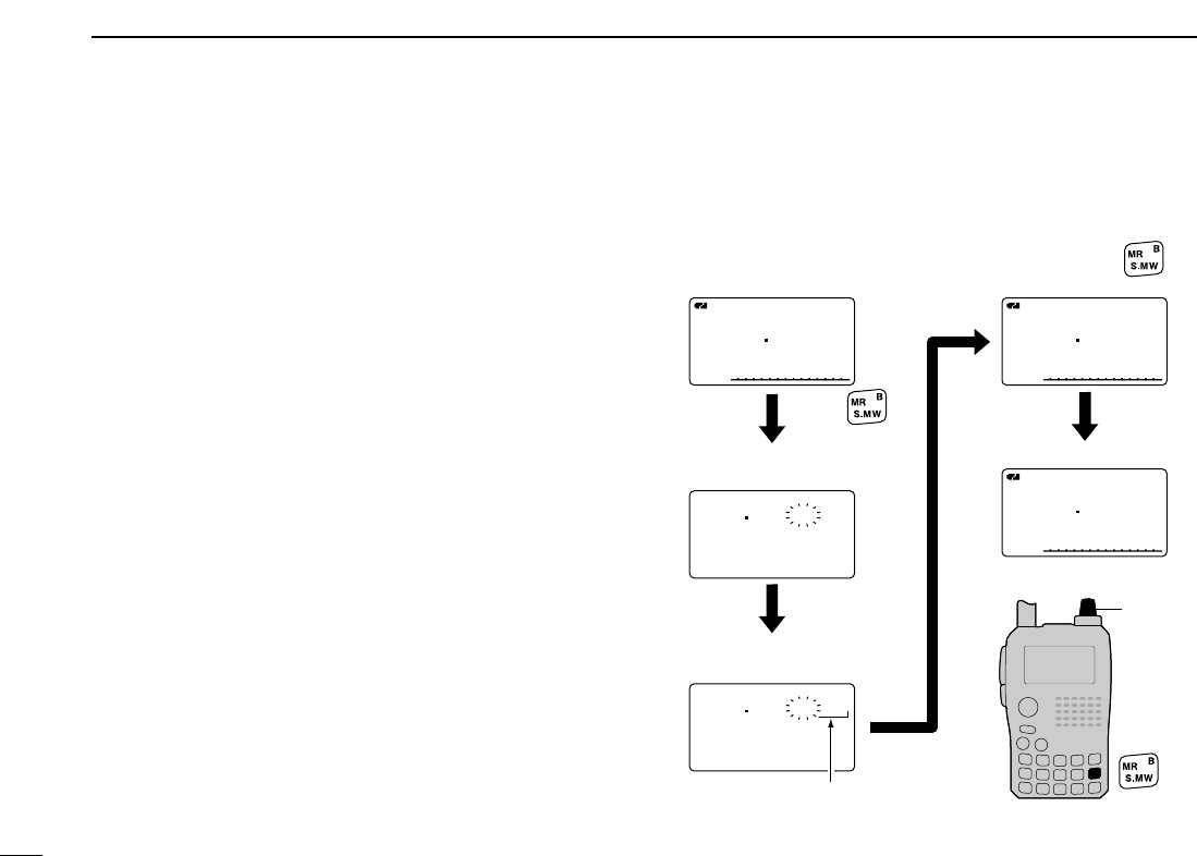
66
8MEMORY/CALL CHANNELS
■
Memory channel programming
qPush [VFO/MHz] to select VFO mode.
wSet the desired frequency:
➥Select the desired band with [BAND].
➥Set the desired frequency with [DIAL].
➥Or set the desired frequency with keypad directly.
In this case, the band and frequency settings with
[BAND] and [DIAL] as above are not required.
➥Set other data (e.g. offset frequency, duplex direction,
tone squelch, etc.), if desired.
ePush and hold [MR/S.MW] for 1 sec. to enter select mem-
ory write mode.
•1 short and 1 long beep sound.
•“
µµ” indicator blinks.
rRotate [DIAL] to select the desired channel.
•Call channels (C0, C1), VFO (VFO) and scan edge channels
(0A/0B to 24A/24B), as well as regular memory channels, can
be programmed in this way.
tPush and hold [MR/S.MW] for 1 sec. to program.
•3 beeps sound.
•Memory channel number automatically increases when contin-
uing to push and holding [MR/S.MW] for 3 sec. after program-
ming.
[EXAMPLE]: Programming 145.870 MHz into memory chan-
nel 11 (blank channel).
[DIAL]
146010
BANKBANK :----:----
MNAME:MNAME:
SKIPSKIP :OFF:OFF
FMFM
r
µ
000
BANKBANK :----:----
MNAME:MNAME:
SKIPSKIP :OFF:OFF
r
µ
011
A
FMFM
145870
PSKIPPSKIP
A
FMFM
145870
PSKIPPSKIP
A
µ
FMFM
145870
PSKIPPSKIP
011
VFO mode
Enter select memory
write mode.
Rotate [DIAL] to select
channel 11.
Push
for 1 sec.
Channel 11
Push and hold
for 1 sec. to program.
Return to the VFO mode
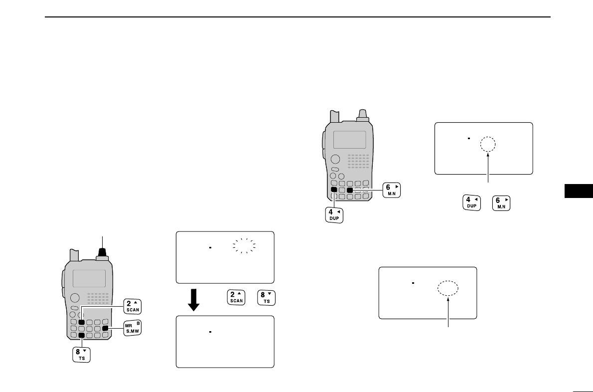
67
8
MEMORY/CALL CHANNELS
1
2
3
4
5
6
7
8
9
10
11
12
13
14
15
16
17
18
19
■Memory bank setting
The IC-91A/91AD has a total of 26 banks (A to Z). Regular
memory channels, 000 to 799 (A band)/000 to 399 (B band),
are assigned into the desired bank for easy memory man-
agement.
qPush and hold [MR/S.MW] for 1 sec. to enter select mem-
ory write mode.
•1 short and 1 long beep sound.
•“
µµ” indicator blinks.
wRotate [DIAL] to select the desired memory channel.
ePush [2/SCAN](∫∫)or [8/TS](√√)to select “BANK.”
•Bank group and channel number is displayed if the selected mem-
ory channel has already been previously assigned into a bank.
rPush [4/DUP](ΩΩ)or [6/M.N](≈≈)several times to select the
desired bank group from “A” to “Z.”
tRotate [DIAL] to select the bank channel number from “00”
to “99.”
•Vacant bank channel numbers will only be displayed.
yPush and hold [MR/S.MW] for 1 sec. to set the channel
into the bank.
•Return to the previous indication.
145870
BANK :C-05
MNAME:
SKIP :OFF
r
µ
011
Bank channel is selec-
ted with [DIAL].
145870
BANK :C-00
MNAME:
SKIP :OFF
r
µ
011
Bank group is selected
with or .
145870
BANK :----
MNAME:
SKIP :OFF
FM
r
µ
011
145870
BANK :----
MNAME:
SKIP :OFF
r
µ
011
[DIAL]
Push or
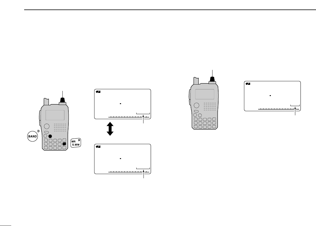
68
8MEMORY/CALL CHANNELS
■Memory bank selection
qPush [MR/S.MW] several times to select memory bank
mode.
wWhile pushing and holding [BAND], rotate [DIAL] to select
the desired bank (A to Z).
•Only programmed banks are displayed.
eRotate [DIAL] to select the bank channel.
•Only programmed channels are displayed.
rPush [MR/S.MW] to return to regular memory condition.
A
µ
FMFM
145620
C01C01
Memory bank mode
[DIAL]
Bank channel is selec-
ted with [DIAL].
A
µ
FMFM
145870
011011
Memory mode
A
µ
FMFM
145870
C05C05
Memory bank mode
Bank channel is
displayed.
Memory channel is
displayed.
[DIAL]
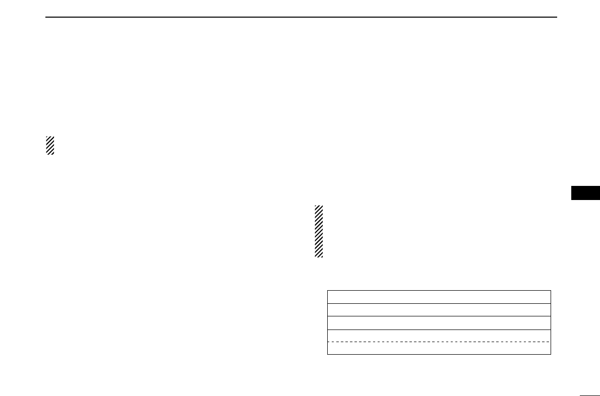
69
8
MEMORY/CALL CHANNELS
1
2
3
4
5
6
7
8
9
10
11
12
13
14
15
16
17
18
19
■Programming memory/bank/scan name
Each memory channel can be programmed with an alphanu-
meric channel name for easy recognition and can be indi-
cated independently by channel. Names can be a maximum
of 8 characters.
NOTE: Scan name indication can be turned ON or OFF in
display set mode. (p. ??)
qPush [MR/S.MW] to select memory mode.
•When programming a call channel name, push [CALL/RX➝CS]
to select call channel mode.
wRotate [DIAL] to select the desired memory channel.
•Select scan edge channels (0A/0B to 24A/24B) for programming
a scan name.
ePush and hold [MR/S.MW] for 1 sec. to enter select mem-
ory write mode.
•1 short and 1 long beep sound.
•“
µµ” indicator blinks.
rPush [2/SCAN](∫∫)or [8/TS](√√)several times to select
“BNAME,” “MNAME” or “SNAME” when programming the
bank name, the memory name or the scan name, respec-
tively.
•After selecting the name programming condition, a cursor blinks
for the first digit.
tRotate [DIAL] to select the desired character.
•The selected character blinks.
•Push [3/LOW](A/a) to change the character group from “AB” (al-
phabetical characters; capital letters), “ab” (alphabetical characters;
small letters), “12” (numbers) and “!''” (symbols) in sequence.
•Push [6/M.N](≈≈)to move the cursor right; push [4/DUP](ΩΩ)to
move the cursor left.
•Push [1/SCOPE](CLR) to erase the selected character, or push
and hold [1/SCOPE](CLR) for 1 sec. to erase following all char-
acters from the cursor.
yRepeat step tuntil the desired channel name is pro-
grammed.
uPush and hold [MR/S.MW] for 1 sec. to program the name
and exit the channel name programming condition.
•3 beeps sound.
NOTE: Only one bank name can be programmed into
each bank. Therefore, the previously programmed bank
name will be displayed when bank name indication is se-
lected. Also, the programmed bank name is assigned for
the other bank channels automatically.
DDAvailable characters
ABCDEFGHIJKLMNOPQRSTUVWXYZ
abcdefghijklmnopqrstuvwxyz
0123456789
! ''#$%&'()*+,-./:;<=>?@[\]
^_`{|}~ (Space)
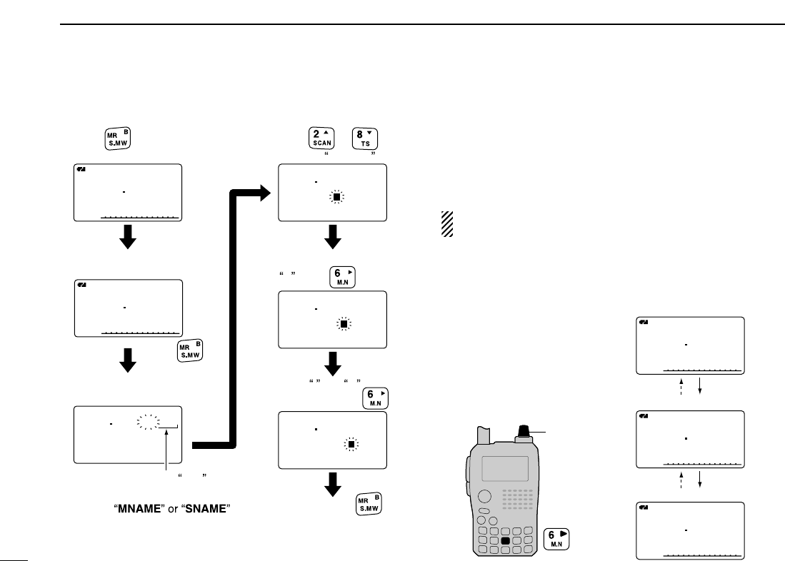
70
8MEMORY/CALL CHANNELS
[EXAMPLE]: Programming the bank name “AIR” into the
scan edge channel 01A. ■Selecting memory/bank name
indication
During memory mode operation, one of the programmed
memory name or bank name can be displayed below the fre-
quency indication.
NOTE: The programmed scan name is displayed during
the programmed scan edge channel selection.
qPush [MR/S.MW] to select memory mode.
wWhile pushing [6 M.N], rotate [DIAL] to select display indi-
cation type from bank name, memory name and OFF.
A
AIR
µ
FMFM
127500
03A
A
Airport1
µ
FMFM
127500
03A
A
µ
FMFM
127500
03A
[DIAL]
Name indication OFF.
Memory name indication
Bank name indication
127500
BANKBANK :A-01:A-01
BNAME: BNAME:
MNAME:MNAME:
SNAME:SNAME:
AMAM
r
µ
03A
A
µ
AMAM
127500
03A
A
µ
FMFM
145870
011
127500
BANKBANK :A-01:A-01
BNAME:AIR BNAME:AIR
MNAME:MNAME:
SNAME:SNAME:
AMAM
r
µ
03A
127500
BANKBANK :A-01:A-01
BNAME:AI BNAME:AI
MNAME:MNAME:
SNAME:SNAME:
AMAM
r
µ
03A
127500
BANKBANK :A-01:A-01
BNAME:A BNAME:A
MNAME:MNAME:
SNAME:SNAME:
AMAM
r
µ
03A
Enter select memory
write mode.
Push
for 1 sec.
Push and hold
for 1 sec. to program.
Push
to select memory mode.
Rotate [DIAL] to select
scan edge channel 03A.
Push
to select BNAME *.
or
Scan edge channel 03A
Rotate [DIAL] to enter
A , push .
Enter I and R
with [DIAL] and .
*Select
when programming the mem-
ory name or the scan name,
respectively.
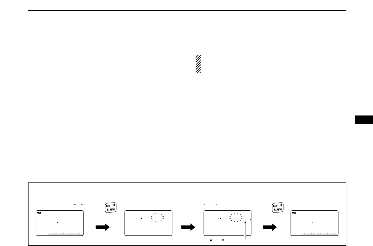
71
8
MEMORY/CALL CHANNELS
1
2
3
4
5
6
7
8
9
10
11
12
13
14
15
16
17
18
19
■Copying memory/call contents
This function transfers a memory channel’s contents to VFO
(or another memory/call channel). This is useful when search-
ing for signals around a memory channel frequency and for
recalling the offset frequency, subaudible tone frequency etc.
DMemory/call➪VFO
qSelect the memory (call) channel to be copied.
➥Push [MR/S.MW] or [CALL/RX➝CS] to select memory
mode or call channel mode, then rotate [DIAL] to select
the desired channel.
wPush and hold [MR/S.MW] for 1 sec. to enter select mem-
ory write mode.
•1 short and 1 long beep sound.
•“
µµ” indicator blinks.
eRotate [DIAL] to select “VFO.”
rPush and hold [MR/S.MW] for 1 sec. to write the selected
channel contents to VFO mode.
•Returns to VFO mode automatically.
Pushing [MR/S.MW] for 2 sec. at the step w, will also
copy the memory contents to VFO. In this case, the steps
eand rare not necessary.
DMemory/call➪memory/call
qSelect the memory (call) channel to be copied.
➥Push [MR/S.MW] or [CALL/RX➝CS] to select memory
mode or call channel mode, then rotate [DIAL] to select
the desired memory channel.
wPush and hold [MR/S.MW] for 1 sec. to enter select mem-
ory write mode.
•1 short and 1 long beep sound.
•“
µµ” indicator blinks.
•Do not hold [MR/S.MW] for more than 2 sec. otherwise the
memory contents will be copied to VFO.
eRotate [DIAL] to select the target memory (call) channel.
rPush and hold [MR/S.MW] for 1 sec. again to copy.
A
FMFM
145870
PSKIPPSKIP
A
µ
FMFM
145870
011
145000
FMFM
µ
VFO
145870
BANKBANK :----:----
MNAME:MNAME:
SKIPSKIP :OFF:OFF
FMFM
r
µ
011
During memory mode,
rotate [DIAL] to select
memory channel 11 .
Rotate [DIAL] to select
VFO . Push
for 1 sec.
Push
for 1 sec.
VFO is selected.
[EXAMPLE]: Copying memory channel 11 to VFO.
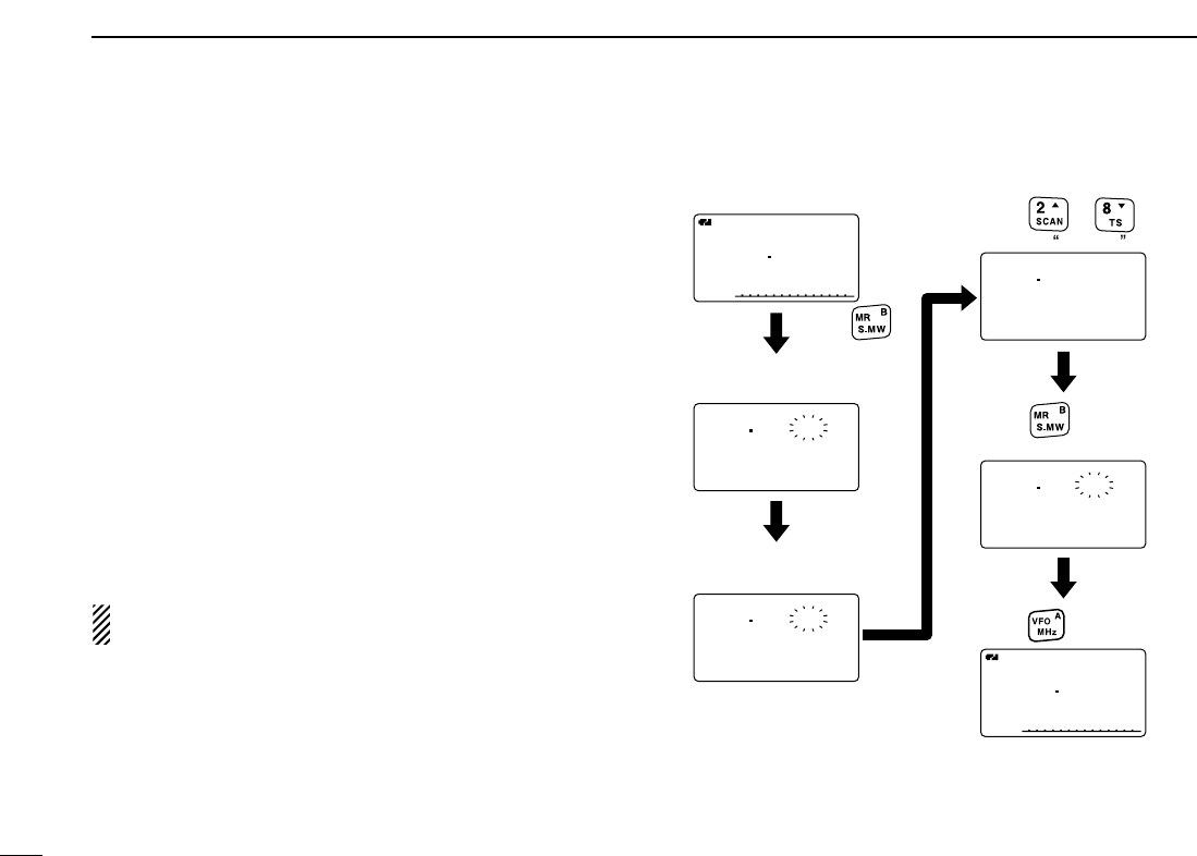
72
8MEMORY/CALL CHANNELS
■Memory clearing
Contents of programmed memories can be cleared (blanked),
if desired.
qPush and hold [MR/S.MW] for 1 sec. to enter select mem-
ory write mode.
•1 short and 1 long beeps sound.
•“
µµ” indicator blinks.
•Do not hold [MR/S.MW] for more than 2 sec. otherwise the
memory contents will be copied to VFO.
wRotate [DIAL] to select the desired memory channel to be
cleared.
ePush [2/SCAN](∫∫)or [8/TS](√√)to select “CLEAR.”
rPush and hold [MR S.MW] for 1 sec. to clear the contents.
•3 beeps sound.
•The cleared channel changes to blank channel
•Return to select memory write mode.— “µµ” indicator blinks.
Push [VFO/MHz] to exit select memory write mode.
NOTE: Be careful!— the contents of cleared memories
CANNOT be recalled even in bank channel operation.
146010
BANKBANK :----:----
MNAME:MNAME:
SKIPSKIP :OFF:OFF
FMFM
r
µ
000
145000
MNAME:MNAME:
SKIPSKIP :OFF:OFF
CLEARCLEAR
r
µ
005
A
FMFM
145870
PSKIPPSKIP
145000
BANKBANK :----:----
MNAME:MNAME:
SKIPSKIP :OFF:OFF
r
µ
005
BANKBANK :----:----
MNAME:MNAME:
SKIPSKIP :OFF:OFF
r
µ
005
A
FMFM
145870
PSKIPPSKIP
VFO mode
Rotate [DIAL] to select
the desired channel.
Push
for 1 sec. to clear.
Push .
Return to the VFO mode.
Enter select memory
write mode.
Push
for 1 sec.
Push
to select CLEAR .
or
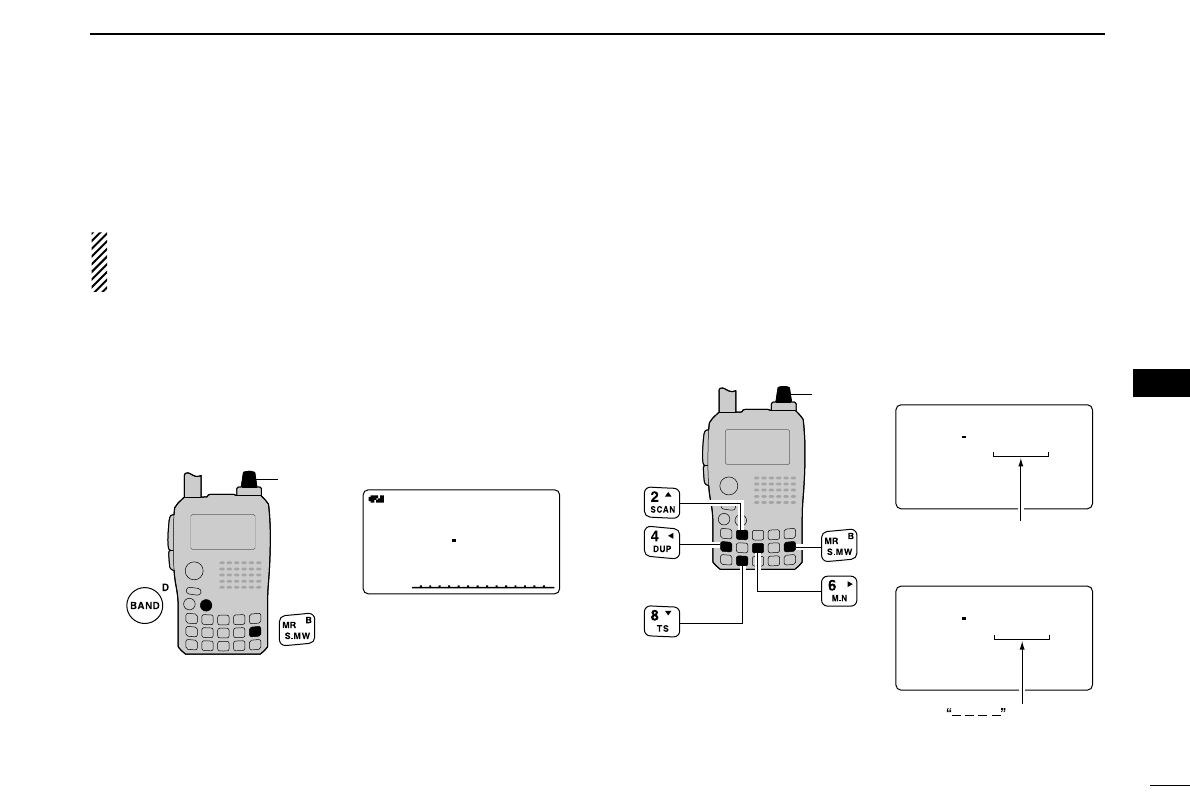
73
8
MEMORY/CALL CHANNELS
1
2
3
4
5
6
7
8
9
10
11
12
13
14
15
16
17
18
19
■Erasing/transferring bank contents
The bank contents of programmed memory channels can be
cleared or reassigned to another memory bank.
INFORMATION: Even if the memory bank contents are
cleared, the memory channel contents still remain pro-
grammed.
qSelect the desired bank contents to be transferred or
erased from the bank. (p. ??)
➥Push [MR/S.MW] several times to select memory bank
mode.
➥While pushing [BAND], rotate [DIAL] to select the de-
sired memory bank group.
➥Rotate [DIAL] to select the bank channel.
wPush [MR/S.MW] for 1 sec. to enter select memory write
mode.
•1 short and 1 long beeps sound.
•Displays the original memory channel number automatically and
“µµ” indicator blinks.
•Do not hold [MR/S.MW] for more than 2 sec., otherwise the
memory contents will be copied to VFO.
ePush [2/SCAN](∫∫)or [8/TS](√√)to select “BANK.”
rPush [6/M.N](≈≈)or [4/DUP](ΩΩ)several times to select the
desired bank group to be transferred.
•Select “– – – –” indication when erasing the contents from the
bank.
tRotate [DIAL] to select the desired bank channel.
•Skip this step when “––––” indication is selected in step r.
yPush [MR/S.MW] for 1 sec. to erase/transfer the bank con-
tents.
145600
BANK :----
BNAME:
MNAME:
SKIP :OFF
FM
r
µ
025
145600
BANK :B-11
BNAME:
MNAME:
SKIP :OFF
FM
r
µ
025
To transfer the bank contents
to ch 11 in Bank B.
To erase
[DIAL]
Bank channel is
displayed.
is displayed.
A
µ
FM
433000
001
A
µ
FM
433000
C05
A
µ
FM
433000
C05
[DIAL]
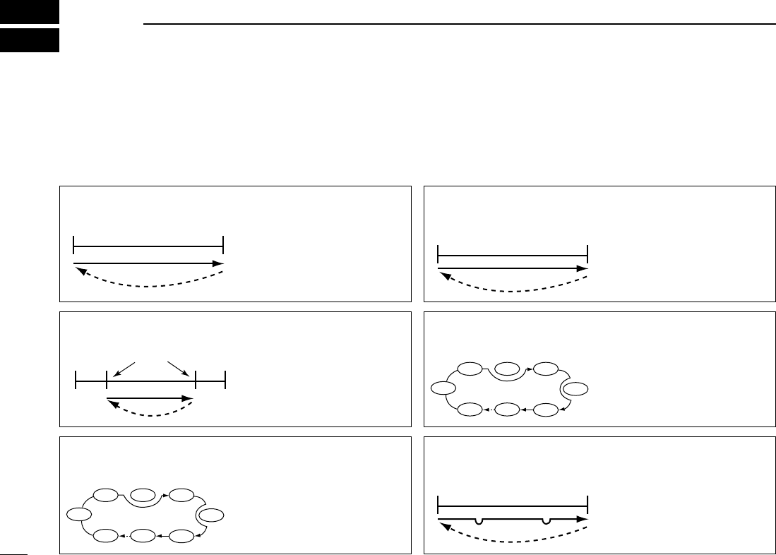
74
SCAN OPERATION
9
■Scan types
Scanning searches for signals automatically and makes it
easier to locate new stations for contact or listening purposes.
There are 7 scan types and 4 resume conditions to suit your
operating needs.
FULL SCAN (p. 00)Repeatedly scans all frequen-
cies over the entire band.
Some frequency ranges are
not scanned according to the
frequency coverage of the
transceiver’s version.
495
kHz
999.990
MHz
Scan
Jump
SELECTED BAND SCAN
(p. 00)
Repeatedly scans all frequen-
cies over the entire selected
band.
Band
edge
Band
edge
Scan
Jump
ALL/SELECTED BANK
SCAN (p. 00)
Repeatedly scans all bank
channels or selected bank
channels. The skip scan is
also available.
SKIP
SKIP
A99 A03
A00 A01 A02
A04
A98
A05
FREQUENCY/MEMORY
SKIP FUNCTION (p. 00)
Skips unwanted frequencies
or channels that inconve-
niently stop scanning. This
function can be turned ON
and OFF by pushing and
holding [5/SKIP] in either
VFO or memory mode.
Band
edge
Band
edge
Scan
SKIP SKIP
Jump
PROGRAMMED SCAN
(p. 00)
Repeatedly scans between
two user-programmed fre-
quencies. Used for checking
for frequencies within a speci-
fied range such as repeater
output frequencies, etc.
Band
edge xxA xxB
Band
edge
Scan edges
Scan
Jump
MEMORY (SKIP) SCAN
(p. 00)
Repeatedly scans memory
channels except those set as
skip channel. Skip channels
can be turned ON and OFF
by pushing and holding [5
/SKIP] in memory mode.
SKIP
SKIP
M 0 M 4
M 1 M 2 M 3
M 5
M 199
M 6
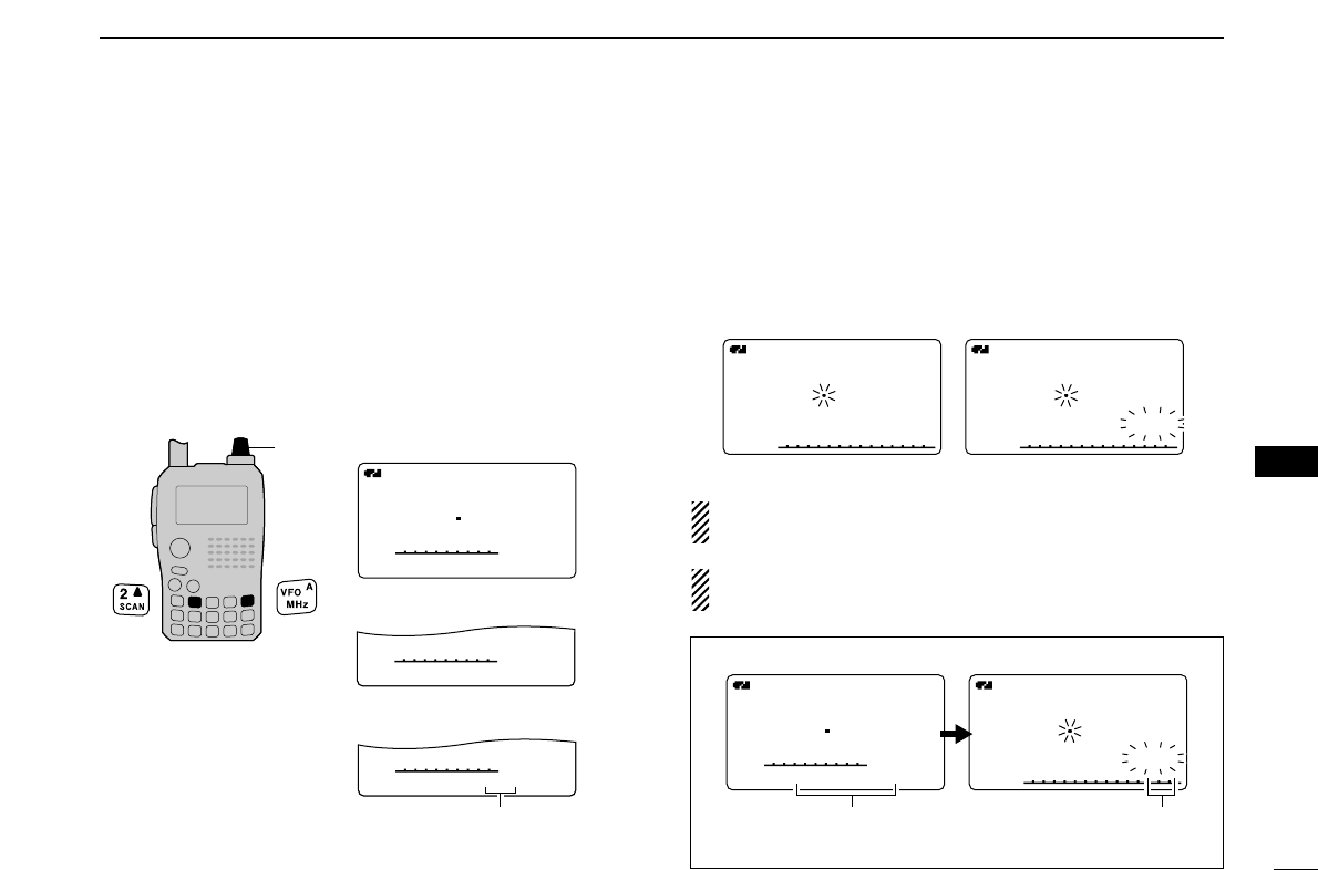
75
9
SCAN OPERATION
1
2
3
4
5
6
7
8
9
10
11
12
13
14
15
16
17
18
19
■Full/band/programmed scan
qPush [VFO/MHz] to select VFO mode.
•Select the desired frequency band with [BAND], if desired.
wSet the squelch level.
eWhile pushing and holding [2/SCAN], rotate [DIAL] to se-
lect the desired scanning type.
•“ALL” for full scan; “BAND” for band scan, “PROG-xx (or scan
name if programmed)” for programmed scan (xx= 0 to 24; pro-
grammed scan edges numbers are only displayed), “DUP” for
duplex scan.
rTo start the scan, release [2/SCAN].
•Scan pauses when a signal is received.
•Rotate [DIAL] to change the scanning direction, or resumes
manually.
•Push [VFO/MHz]to stop the scan.
About the scanning steps: The selected tuning step in
each frequency band (in VFO mode) is used during scan.
Duplex scan function: Repeatedly scans two frequencies
(transmission/reception) during duplex scan operation.
FMFM
A
148800
FMFM
A
PSKIPSKIP PSKIPSKIP
P01P01
148800
• During full/band scan • During programmed scan
FMFM
A
146010
SCAN:ALL
FM
A
148800
SCAN:BAND
FM
A
148800
SCAN:PROG-01
PSKIPSKIP
PSKIPSKIP
PSKIPSKIP
• Full scan selection
• Programmed scan selection
• Band scan selection
Selectable between 00 to 24
if programmed
[DIAL]
FMFM
A
148800
PSKIPSKIP
P01P01
FMFM
A
148800
PSKIPSKIP
SCAN:SCANNAME
Scan name
Scan name is not displayed during a programmed scan.
Scan edge number
Scan name selection
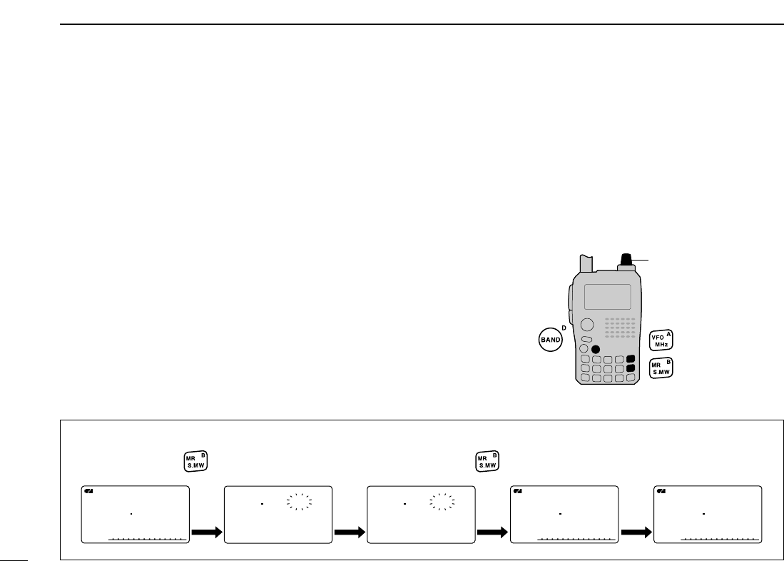
76
9SCAN OPERATION
■Scan edges programming
Scan edges can be programmed in the same manner as
memory channels. Scan edges are programmed into scan
edges, 00A/00B to 24A/24B, in memory channels.
qPush [VFO/MHz] to select VFO mode.
wSet the desired frequency:
➥Select the desired band with [BAND].
➥Set the desired frequency with [DIAL].
➥Set other data (e.g. offset frequency, duplex direction, tone
squelch, etc.), if desired.
ePush and hold [MR/S.MW] for 1 sec. to enter the select
memory write mode.
•1 short and 1 long beeps sound.
•“
µµ” indicator blinks.
rRotate [DIAL] to select the desired programmed scan
edge channel from 00A to 24A.
tPush and hold [MR/S.MW] for 1 sec.
•3 beeps sound.
•The other scan edge channel “B,” 00B to 24B, automatically se-
lected when continuing to push [MR/S.MW] after programming.
yTo program a frequency for the other pair of scan edges,
00B to 24B, repeat steps wand r.
•If the same frequency is programmed into a pair of scan edges,
programmed scan will not function.
[DIAL]
[EXAMPLE]: Programming 145.300 MHz into scan edges 03A.
A
FMFM
145300
PSKIPSKIP
A
FMFM
145300
PSKIPSKIP
03A
A
FMFM
145300
PSKIPSKIP
146010
BANKBANK :----:----
MNAME:MNAME:
SKIPSKIP :OFF:OFF
FMFM
r
µ
001
BANKBANK :----:----
MNAME:MNAME:
SNAME:SNAME:
FMFM
r
µ
03A
Push for 1 sec. Rotate [DIAL] Push for 1 sec.
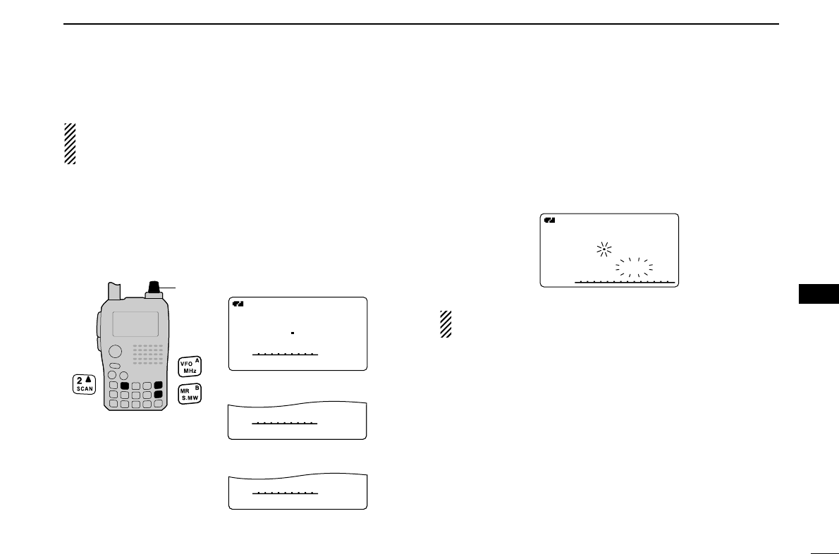
77
9
SCAN OPERATION
1
2
3
4
5
6
7
8
9
10
11
12
13
14
15
16
17
18
19
■Memory scan
IMPORTANT!: To perform memory scan, 2 or more mem-
ory channels MUST be programmed, otherwise the scan
will not start.
qPush [MR/S.MW] to select memory mode.
wSet the squelch level.
eWhile pushing and holding [2/SCAN], rotate [DIAL] to se-
lect the desired scanning type.
•“ALL” for full memory scan; “BAND” for band memory scan,
“MODE” for mode scan, “DUP” for duplex scan.
rRelease [2/SCAN] to start the selected scan.
•Scan pauses when a signal is received.
•Rotate [DIAL] to change the scanning direction, or resumes
manually.
tTo stop the scan, push [VFO/MHz].
Duplex scan function: Repeatedly scans two frequencies
(transmission/reception) during duplex scan operation.
FM
A
µ
012
148800
• During memory scan
FMFM
A
146010
µ
088088
SCAN:ALL
FM
A
148800
µ
088088
SCAN:BAND
FM
A
148800
µ
088088
SCAN:MODE
PSKIPSKIP
PSKIPSKIP
PSKIPSKIP
¥ All memory scan selection
¥ Mode scan selection
¥ Band memory scan selection
[DIAL]
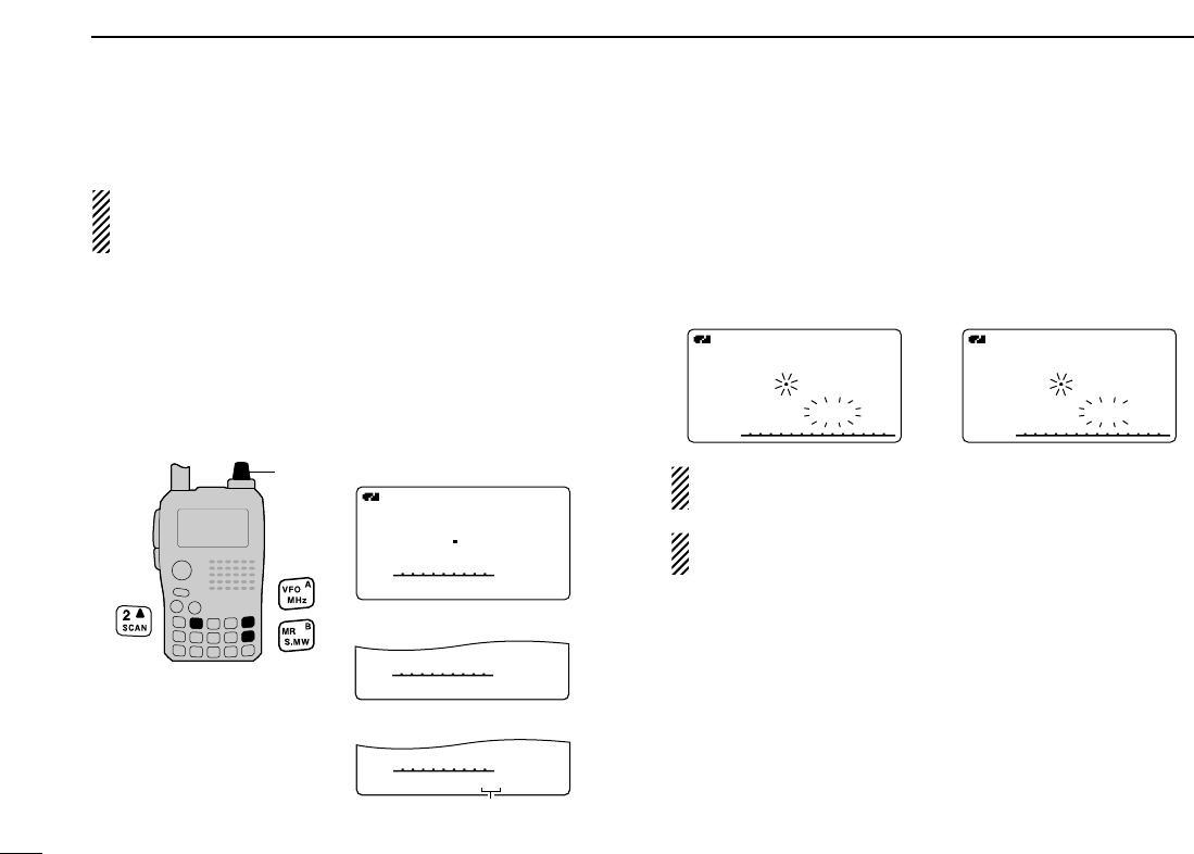
78
9SCAN OPERATION
■Memory bank scan
IMPORTANT!: To perform memory bank scan, 2 or more
bank channels MUST be programmed, otherwise the scan
will not start.
qPush [MR/S.MW] several times to select memory bank
mode.
wSet the squelch level.
eWhile pushing and holding [2/SCAN], rotate [DIAL] to se-
lect the desired scanning type.
•“ALL” for all bank scan; “BANK-LINK” for bank link scan or
“BANK-x” for bank scan (x= A to Z; programmed bank groups
are only displayed.), “DUP” for duplex scan.
rRelease [2/SCAN] to start the selected scan.
•Scan pauses when a signal is received.
•Rotate [DIAL] to change the scanning direction, or resumes
manually.
tTo stop the scan, push [VFO/MHz].
The bank-link setting can be changed in scan set mode.
See page 00 for details.
Duplex scan function: Repeatedly scans two frequencies
(transmission/reception) during duplex scan operation.
FM
A
µ
888
148800
• During all bank/bank link scan • During bank scan
FM
A
µ
A88
148800
FMFM
A
146010
µ
A01A01
SCAN:ALL
FM
A
148800
µ
A01A01
SCAN:BANK-LINK
FM
A
148800
µ
A01A01
SCAN:BANK-A
PSKIPSKIP
PSKIPSKIP
PSKIPSKIP
¥ All bank scan selection
¥ Bank scan selection
¥ Bank link scan selection
Selectable between A to Z
if programmed
[DIAL]
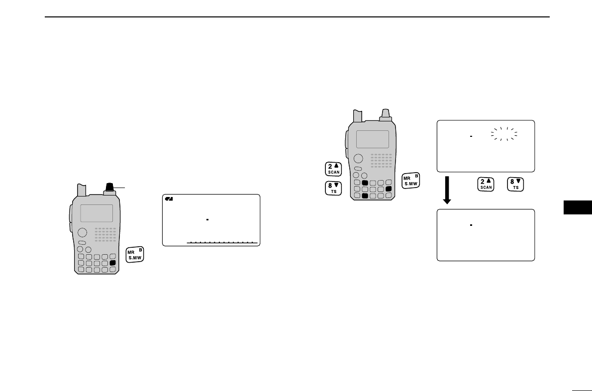
79
9
SCAN OPERATION
1
2
3
4
5
6
7
8
9
10
11
12
13
14
15
16
17
18
19
■Skip channel/frequency setting
Memory channels can be set to be skipped for memory skip
scan. In addition, memory channels can be set to be skipped
for both memory skip scan and frequency skip scan. These
are useful to speed up the scan interval.
qSelect a memory channel:
➥Push [MR/S.MW] to select memory mode.
➥Rotate [DIAL] to select the desired channel to be a skip
channel/frequency.
wPush and hold [MR/S.MW] for 1 sec. to enter select mem-
ory write mode.
ePush [2/SCAN](∫∫)or [8/TS](√√)several times to select
“SKIP.”
rRotate [DIAL] to select the skip condition from “SKIP,” “P
SKIP” or “OFF” for the selected channel.
•P SKIP: The channel is skipped during memory/bank scan and
the programmed frequency is skipped during VFO scan,
such as programmed scan.
•SKIP : The channel is skipped during memory or bank scan.
•OFF : The channel or programmed frequency is scanned dur-
ing any scan.
(Continue to the next page.)
146010
BANK :----
MNAME:
SKIP :OFF
FMFM
r
µ
012
146010
MNAME:
SKIP :OFF
CLEAR
FMFM
r
µ
012
or
several times.
Push
FMFM
A
µ
020020
145870
[DIAL]
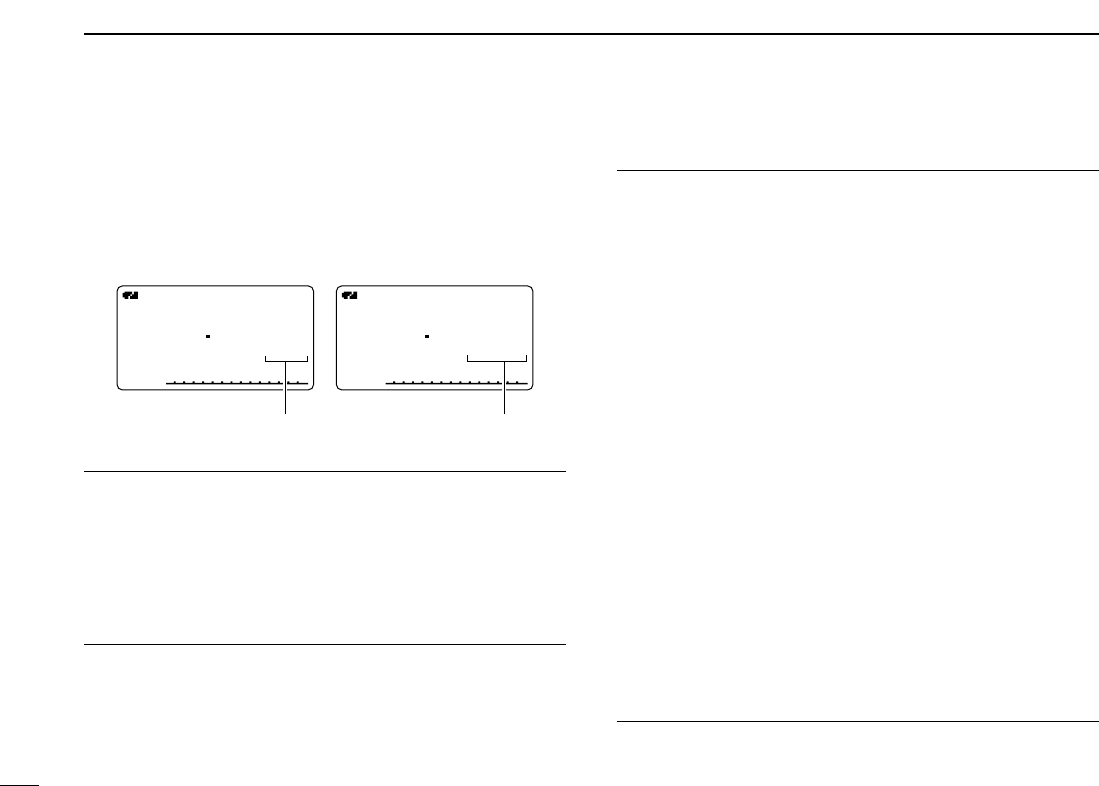
80
9SCAN OPERATION
tPush and hold [MR/S.MW] for 1 sec. to store the skip con-
dition into the memory.
•“SKIP” or “P SKIP” indicator appears, according to the skip se-
lection in the step r.
✔
CONVENIENT!
Also the skip setting can be set with the following operation
for easy setting.
qSelect the desired memory channel to be set as a skip
channel/frequency.
w
While pushing [5/SKIP], rotate [DIAL] to select the skip con-
dition from “P SKIP,” “SKIP” and “OFF (no indication).”
✔
CONVENIENT!
During VFO scanning, such as programmed scan, the skip
setting can be programmed into the highest blank memory
channel which is automatically selected with the following op-
eration.
qStart the VFO scan.
➥Push [VFO/MHz]to select VFO mode.
•Select the desired frequency band with [BAND], if desired.
➥ Set the squelch level.
➥While pushing and holding [2/SCAN], rotate [DIAL] to
select the desired scanning type.
•“ALL” for full scan; “BAND” for band scan, “PROG-xx (or scan
name if programmed)” for programmed scan (xx= 0 to 24;
programmed scan edges numbers are only displayed), “DUP”
for duplex scan.
➥ To start the scan, release [2/SCAN].
•Scan pauses when a signal is received.
•Rotate [DIAL] to change the scanning direction, or resumes
manually.
wWhen scan pauses and you want to set the paused fre-
quency as a skip frequency.
➥ Push and hold [5/SKIP] for 1 sec. to store the paused
frequency into the highest blank memory channel.
•While pushing and holding [5/SKIP], scan pauses; and after
writing the frequency, scan resumes.
FMFM
A
µ
SKIPSKIP
033033
145700
FMFM
A
µ
PSKIPSKIP
033033
145700
¥ Skip channel setting ¥ Program skip setting
SKIP appears P SKIP appears

■Scan resume condition
DDScan pause timer
The scan pauses when receiving signals according to the
scan pause time. It can be set from 2 to 20 sec. or unlimited.
qEnter “PAUSE” in scan set mode. (p. 00)
wRotate [DIAL]†to set the desired scan pausing time from
2–20 sec. (2 sec. steps) or “HOLD.”
•“2SEC”–“20SEC”: Scan pauses for 2–20 sec. while receiving a
signal.
•“HOLD”: Scan pauses on a received a signal until it
disappears.”
ePush [5/SKIP](ï)to set the scan pause timer,and return
to scan set mode.
r[MENU/LOCK] to return to frequency indication.
DDScan resume timer
The scan restarts after the signal disappears according to the
resume time. It can be set from 0–5 sec. or unlimited.
qEnter “RESUME” in scan set mode. (p. 00)
wRotate [DIAL]†to set the desired scan resume time from
0–5 sec. (1 sec. steps) and “HOLD.”
•“0SEC”: Scan restarts immediately after the signal dis-
appears.
•“1SEC”–“5SEC”: Scan restarts 1–5 sec. after the signal disap-
pears.
•“HOLD”: Scan restarts by rotating [DIAL] only.
ePush [5/SKIP](ï)to set the scan pause timer,and return
to scan set mode.
r[MENU/LOCK] to return to frequency indication.
Scan resume timer must be set shorter than the scan
pause timer, otherwise this timer does not activate.
¥ Resume timer setting
2SEC2SEC
4SEC4SEC
3SEC3SEC
1SEC1SEC
5SEC5SEC
RESUME TIMER
r
MENU screen➪SCAN➪RESUME
(Push [MENU/LOCK]) (Rotate [DIAL]†, then push [5/SKIP](ï)†.)
10SEC10SEC
6SEC6SEC
8SEC8SEC
4SEC4SEC
12SEC12SEC
PAUSE TIMER
r
• Pause timer setting
MENU screen➪SCAN➪PAUSE
(Push [MENU/LOCK]) (Rotate [DIAL]†, then push [5/SKIP](ï)†.)
81
9
SCAN OPERATION
1
2
3
4
5
6
7
8
9
10
11
12
13
14
15
16
17
18
19
†[DIAL] ↔[2/SCAN](∫∫)/[8/TS](√√)
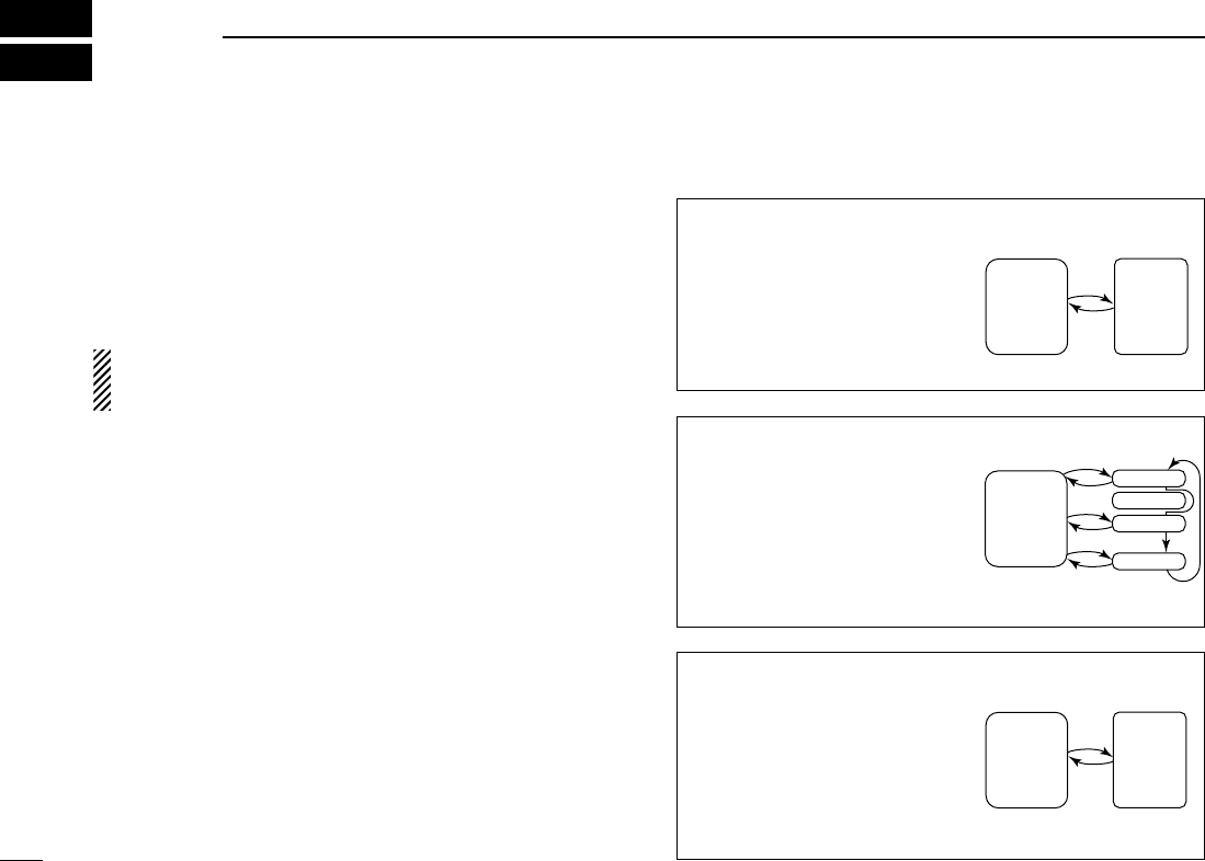
82
PRIORITY WATCH
10
■Priority watch types
Priority watch checks for signals on the frequency every
5 sec. while operating on a VFO frequency or scanning. The
transceiver has 3 priority watch types to suit your needs.
The watch resumes according to the selected scan resume
condition. See the left page for details.
NOTE: If the pocket beep function is activated, the trans-
ceiver automatically selects the tone squelch function
when priority watch starts.
DDAbout priority beep function
When receiving a signal on the priority frequency, you can be
alerted with beeps and a blink “S.” This function can be
activated when setting the priority watch function ON.
MEMORY/CALL CHANNEL WATCH
While operating on a VFO fre-
quency, priority watch checks for
a signal on the selected memory
or call channel every 5 sec.
•A memory channel with skip infor-
mation can be watched.
MEMORY SCAN WATCH
While operating on a VFO fre-
quency, priority watch checks for
signals on each memory chan-
nel in sequence.
•The memory skip function and/or
memory bank scan is useful to
speed up the scan.
5 sec.
VFO
frequency
Memory
(Call)
channel
5 sec.
VFO
frequency
SKIP
Mch 000
Mch 001
Mch 001
Mch 999
VFO SCAN WATCH
While scanning in VFO mode,
priority watch checks for signals
on the selected memory or call
channel every 5 sec.
5 sec.
VFO
scan
Memory
(Call)
channel
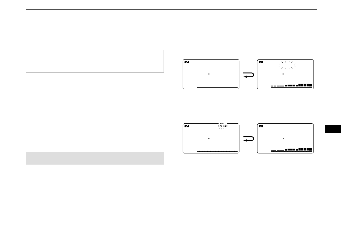
■Priority watch operation
DDMemory/call channel and memory scan watch
qSelect VFO mode; then, set an operating frequency.
wSet the watching channel(s).
For memory channel watch:
Select the desired memory channel.
For call channel watch:
Select the desired call channel.
For memory scan watch:
Select memory mode, or the desired bank group; then,
push and hold [2/SCAN] for 1 sec. to start memory/bank
scan.
eEnter “PRIO WATCH” in scan set mode. (p. 00)
rRotate [DIAL]†to select “ON.”
• Select “BELL” if the priority beep function is necessary.
tPush [VFO/MHz] to exit scan set mode and start the
watch.
•“PRIO” indicator appears.
•The transceiver checks the memory/bank channel(s) or call
channel every 5 sec.
•The watch resumes according to the selected scan resume con-
dition. (p. 00)
yPush [VFO/MHz] to cancel the watch.
¥ During priority watch
Monitors VFO frequency
for 5 sec.
Pauses on a memory or
call channel when a sig-
nal is received.
¥ During priority watch with priority beep
Emits beep and blinks S indicator when a signal is re-
ceived on a memory or call channel.
PRIOPRIOFMFM
A
145180
µ
035035
PRIOPRIOFMFM
A
433260
PSKIPSKIP
PRIOPRIOFMFM
A
145180
µ
035035
PRIOPRIOFMFM
A
433260
PSKIPSKIP
MENU screen➪SCAN➪PRIO WATCH
(Push [MENU/LOCK]) (Rotate [DIAL]†, then push [5/SKIP](ï)†.)
Although [DIAL] and [5/SKIP](ï)are used for description
in this section, [2/SCAN](∫∫)/[8/TS](√√)and [6/M.N](≈≈)are
available instead of [DIAL] and [5/SKIP](ï).
83
10
PRIORITY WATCH
1
2
3
4
5
6
7
8
9
10
11
12
13
14
15
16
17
18
19
†[DIAL] ↔[2/SCAN](∫∫)/[8/TS](√√) [5/SKIP](ï)↔[6/M.N](≈≈)
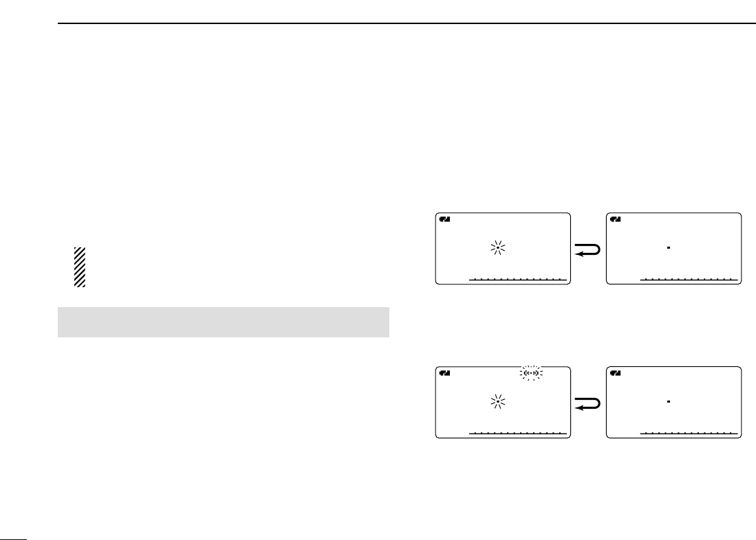
84
10 PRIORITY WATCH
DDVFO scan watch
qSet the watching channel(s).
For memory channel watch:
Select the desired memory channel.
For call channel watch:
Select the desired call channel.
For memory scan watch:
Select memory mode, or the desired bank group; then,
push and hold [2/SCAN] for 1 sec. to start memory/bank
scan.
While scanning memory/bank channels:
Starts memory/bank scan first. Memory/bank scan can-
not be started after VFO scan is started.
wEnter “PRIO WATCH” in scan set mode. (p. 00)
eRotate [DIAL]†to select “ON.”
• Select “BELL” if the priority beep function is necessary.
rPush [VFO/MHz] to exit scan set mode and start the
watch.
•“PRIO” indicator appears.
tPush and hold [2/SCAN] for 1 sec. to enter scan type se-
lection condition.
yRotate [DIAL] to select the desired scan type from “ALL,”
“BAND” and “PROG-xx (xx= 0–24),” “DUP.”
uRelease [2/SCAN] to start the VFO scan watch.
•The transceiver checks the memory/bank channel(s) or call
channel every 5 sec.
•The watch resumes according to the selected scan resume con-
dition. (p. 00)
iPush [VFO/MHz] to cancel the watch.
¥ During priority watch
Searches VFO frequencies
for 5 sec.
Pauses on a memory or
call channel when a sig-
nal is received.
¥ During priority watch with priority beep
Emits beep and blinks S indicator when a signal is re-
ceived on a memory or call channel.
PRIOPRIOFMFM
A
145000
µ
000000
PRIOPRIOFMFM
A
888800
PSKIPSKIP
PRIOPRIOFMFM
A
145000
µ
000000
PRIOPRIOFMFM
A
888800
PSKIPSKIP
MENU screen➪SCAN➪PRIO WATCH
(Push [MENU/LOCK]) (Rotate [DIAL]†, then push [5/SKIP](ï)†.)
†[DIAL] ↔[2/SCAN](∫∫)/[8/TS](√√) [5/SKIP](ï)↔[6/M.N](≈≈)
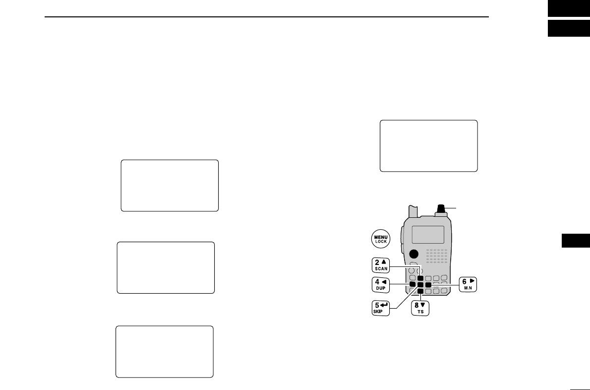
85
11
MENU SCREEN OPERATION
1
2
3
4
5
6
7
8
9
10
11
12
13
14
15
16
17
18
19
■General
MENU screen is used for programming infrequently changed
values or conditions of functions.
DDEntering MENU screen and operation
e.g.) Set “AUTO power OFF” to 30 minutes.
qPush [MENU/LOCK] to enter MENU screen.
wRotate [DIAL]†to select the desired menu group, then
push [5/SKIP](ï)†.
eRotate [DIAL]†to select the desired item, then push
[5/SKIP](ï)†.
rRotate [DIAL]†to select the desired value or condition,
then push [5/SKIP](ï)†to return to the setting item selec-
tion mode.
tPush [MENU/LOCK] to return to frequency indication, re-
peat steps wto rto set another items.
[DIAL]
OFFOFF
30MIN30MIN
60MIN60MIN
90MIN90MIN
120MIN120MIN
AUTO POWER OFF
r
OFFOFF
30MIN30MIN
60MIN60MIN
90MIN90MIN
120MIN120MIN
AUTO POWER OFF
r
AP OFFAP OFF
POWER SAVEPOWER SAVE
ATTENUATORATTENUATOR
MONITORMONITOR
DIAL SPEEDDIAL SPEED
SET MODE
r
• Setting items
appear.
SET MODESET MODE
SCANSCAN
DUP/TONE...DUP/TONE...
DISPLAYDISPLAY
SOUNDSSOUNDS
***** MENU *****
r
• MENU groups
appear.
†[DIAL] ↔[2/SCAN](∫∫)/[8/TS](√√) [5/SKIP](ï)↔[6/M.N](≈≈)
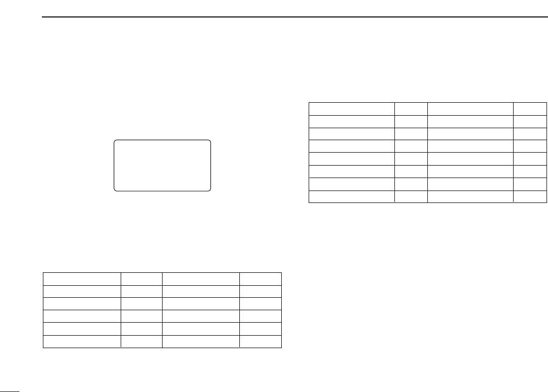
86
11 MENU SCREEN OPERATION
■MENU screen indication for
B band*
While B band is selected, MENU screen shows following in-
dication.
select B band by pushing [BAND].
*The optional UT-121 is required for IC-91A.
■Menu list
† Refer to the chapter 7 for details.
■Items list
DDSet mode
AUTO POWER OFF
POWER SAVE
ATTENUATOR
MONITOR
DIAL SPEED-UP
AUTO REPEATER
MIC SIMPLE MODE
ITEMS
p. 103
p. 103
p. 103
p. 103
p. 103
p. 103
p. 103
REF.
AUTO POWER ON
LOCK
PTT LOCK
BUSY LOCKOUT
TIME-OUT TIMER
ACTIVE BAND
ITEMS
p. 103
p. 103
p. 103
p. 103
p. 103
p. 103
REF.
pgs.103–103
pgs.103–103
pgs.103–103
pgs.103–103
pgs.103–103
—
—
—
—
pgs.103–103
CALL SIGN†
RX CALL SIGN†
MESSAGE/POSITION†
DV VOICE MEMO†
SET MODE
MENU REF.
DV SET MODE
SCAN
DUP/TONE...
DISPLAY
SOUNDS
MENU REF.
RX CALL SRX CALL S
MESSAGE/POSMESSAGE/POS
DV VOICE MDV VOICE M
SET MODESET MODE
DV SET MODEDV SET MODE
***** MENU ********** MENU *****
r
MENU screen indication for B band.
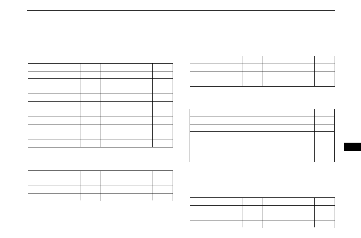
87
11
MENU SCREEN OPERATION
1
2
3
4
5
6
7
8
9
10
11
12
13
14
15
16
17
18
19
DDDV set mode
Available for B band of IC-91AD, or UT-121 is installed IC-
91A only.
DDScan set mode
‡Not available during the TV band selection.
DDDUP/TONE set mode
Not available for the TV band.
DDDISPLAY set mode
*1Available for B band of IC-91AD, or UT-121 is installed IC-91A only.
*2 Available for IC-91AD, or UT-121 is installed IC-91A only.
DDSOUNDS set mode
✱1Available for B band of IC-91AD, or UT-121 is installed IC-91A only.
BEEP LEVEL
KEY-TOUCH BEEP
SCAN STOP BEEP
ITEMS
p. 103
p. 103
p. 103
REF.
SCOPE AF OUTPUT
VOLUME SELECT
STANDBY BEEP*1
ITEMS
p. 103
p. 103
p. 103
REF.
BACKLIGHT
BUSY LED
LCD CONTRAST
RX CALL SIGN*1
TX CALL SIGN*1
RX MESSAGE*1
ITEMS
p. 103
p. 103
p. 103
p. 103
p. 103
p. 103
REF.
SCAN NAME
OPENING LOGO
OPENING CALL S*2
FONT SIZE
LANGUAGE
ITEMS
p. 103
p. 103
p. 103
p. 103
p. 103
REF.
OFFSET FREQ
REPEATER TONE
CTCSS TONE
ITEMS
p. 103
p. 103
p. 103
REF.
DTCS CODE
DTCS POLARITY
DTMF SPEED
ITEMS
p. 103
p. 103
p. 103
REF.
PRIO WATCH‡
PAUSE TIMER
RESUME TIMER
ITEMS
p. 103
p. 103
p. 103
REF.
BANK LINK
➥ BANK-A
ITEMS
p. 103
p. 103
p. 103
REF.
AUTO REPLY
DIGITAL CODE
DV DATA TX
DIGITAL MONITOR
DIGITAL RPT SET
RXCALL WRITE
RXRPT WRITE
ITEMS
p. 103
p. 103
p. 103
p. 103
p. 103
p. 103
p. 103
REF.
GPS MODE
➥ GPS SENTENCE
➥ RMC SENTENCE
GGA SENTENCE
GLL SENTENCE
GSA SENTENCE
VTG SENTENCE
GPS AUTO TX
DV AUTO DETECT
EDIT RECORD
ITEMS
p. 103
p. 103
p. 103
p. 103
p. 103
p. 103
p. 103
p. 103
p. 103
p. 103
REF.

88
11 MENU SCREEN OPERATION
■Set mode items
DDAuto power OFF
The transceiver can be set to automatically turn OFF after a
specified time period with a beep when no key operations are
performed.
30 min., 60 min, 90 min, 120 min and OFF (default) can be
specified. The specified time period is retained even when the
transceiver is turned OFF by the auto power OFF function. To
cancel the function, select “OFF” in this item.
DDPower save
The power save function reduces the current drain to con-
serve battery power. This power save function can be turned
OFF, if desired.
In the default setting (“AUTO” selection), the power save func-
tion is activated in 1:1 (150 msec.: 150 msec.) ratio when no sig-
nal is received for 5 sec. The ratio becomes 1:4 (150 msec.:
600 msec.) when no signal is received for another 60 sec.
Then the ratio becomes 1:8 (150 msec.: 1200 msec.) when no
signal is received for another more 60 sec.
DDAttenuator
The attenuator prevents distortion of a desired signal when
very strong RF signals are near the desired frequency or
when very strong electric fields, such as from a broadcasting
station, are present at your location.
Select the attenuator function ON and OFF (default).
OFFOFF
ONON
ATTENUATOR
r
ONON
OFFOFF
ATTENUATOR
r
AUTOAUTO
OFFOFF
POWER SAVE
r
OFFOFF
AUTOAUTO
POWER SAVE
r
OFFOFF
30MIN30MIN
60MIN60MIN
90MIN90MIN
120MIN120MIN
AUTO POWER OFFAUTO POWER OFF
r
30MIN30MIN
OFFOFF
60MIN60MIN
90MIN90MIN
120MIN120MIN
AUTO POWER OFF
r

89
11
MENU SCREEN OPERATION
1
2
3
4
5
6
7
8
9
10
11
12
13
14
15
16
17
18
19
DDMonitor key action
The monitor key, [SQL] , can be set as a ‘sticky’key. When
set to the sticky condition, each push of [SQL] toggles the
monitor function ON and OFF.
•PUSH: Pushing and holding [SQL] to monitor the fre-
quency. (default)
•HOLD : Push [SQL] momentarily to monitor the frequency
and push momentarily again to cancel it.
DDDial speed acceleration
The dial speed acceleration automatically speeds up the tun-
ing dial speed when rotating [DIAL] rapidly.
•OFF : The dial speed acceleration is turned OFF.
•ON : The dial speed acceleration is tuned ON.
(default)
DDAuto repeater
The auto repeater function automatically turns ON or OFF the
duplex operation and tone encoder. The offset and repeater
tone is not changed by the auto repeater function. Reset
these frequencies, if necessary.
U.S.A. version:
•OFF : The auto repeater function is turned OFF.
•RPT1 : Activates for duplex only. (default)
•RPT2 : Activates for duplex and tone.
Korea version:
•OFF : Deactivates the function.
•ON : Activates duplex and tone. (default)
ONON
OFFOFF
AUTO REPEATER
r
OFFOFF
ONON
AUTO REPEATER
r
RPT1RPT1
OFFOFF
RPT2RPT2
AUTO REPEATER
r
OFFOFF
RPT1RPT1
RPT2RPT2
AUTO REPEATER
r
U.S.A./KOREAN versions only
ONON
OFFOFF
DIAL SPEED-UP
r
OFFOFF
ONON
DIAL SPEED-UP
r
PUSHPUSH
HOLDHOLD
MONITOR
r
HOLDHOLD
PUSHPUSH
MONITOR
r

90
11 MENU SCREEN OPERATION
DDMicrophone simple mode
Microphone simple mode is used to change the function as-
signments for keys on the optional HM-75A
REMOTE CONTROL
SPEAKER
-
MICROPHONE
. (p. ??)
•SIMPLE
•NORM-1 (default)
•NORM-2
DDWeather alert function
Turns weather alert function ON and OFF. (p.???)
(default: OFF)
DDAuto power ON
Auto power ON function turns the transceiver power ON au-
tomatically after passing the set time period from power OFF.
Select the desired time period within 30 minutes to 24 hours
in 30 minutes steps and OFF. (default: OFF)
DDKey lock Type
While the key lock function is ON, [PWR], [PTT], [SQL],
[VOL] and [MENU](Lock function only) can still be accessed.
Accessible keys can be set to 1 of 4 groups.
•NORMAL : [PWR], [PTT], [SQL], [VOL] and [MENU]
(Lock function only) accessible. (default)
•NO SQL : [PWR], [PTT], [SQL], and [MENU] (Lock func-
tion only) are accessible.
•NO VOL : [PWR], [PTT], [VOL], and [MENU] (Lock func-
tion only) are accessible.
•ALL : [PWR], [PTT] and [MENU] (Lock function only)
are accessible.
NORMALNORMAL
NO SQLNO SQL
NO VOLNO VOL
ALLALL
LOCK
r
NORMALNORMAL
NO SQLNO SQL
NO VOLNO VOL
ALLALL
LOCK
r
OFFOFF
AUTO POWER ON
24:0024:00
AUTO POWER ON
OFFOFF
ONON
WEATHER ALERT WEATHER ALERT
r
OFFOFF
ONON
WEATHER ALERT
r
U.S.A. version only
NORM-1NORM-1
SIMPLESIMPLE
NORM-2NORM-2
MIC SIMPLE MODEMIC SIMPLE MODE
r
SIMPLESIMPLE
NORM-1NORM-1
NORM-2NORM-2
MIC SIMPLE MODE
r

91
11
MENU SCREEN OPERATION
1
2
3
4
5
6
7
8
9
10
11
12
13
14
15
16
17
18
19
DDPTT lock
Turns the PTT lock function ON and OFF.
Transmission with [PTT] is inhibited when ON is selected to
prevent accidental transmission, etc. (default: OFF)
DDBusy lockout
Turns the busy lockout function ON and OFF.
This function inhibits transmission while receiving a signal or
when the squelch is open. (default: OFF)
DDTime-out timer
To prevent accidental prolonged transmission, etc., the trans-
ceiver has a time-out timer. This function cuts a transmission
OFF after 1, 3, 5 or 10 min. of continuous transmission. This
timer can be cancelled.
•OFF : The time-out timer is turned OFF. (default)
•1 to 10 MIN : The transmission is cut OFF after the set
period elapses.
DDActive band
Allows continuous frequency selection of the operating fre-
quency across all bands.
• SINGLE : The operating frequency can be selected
within the current band. Push [BAND] for
band selection in this case.
•ALL : The operating frequency can be selected
continuously. (default)
ALLALL
SINGLESINGLE
ACTIVE BAND
r
ALLALL
SINGLESINGLE
ACTIVE BAND
r
OFFOFF
1MIN1MIN
3MIN3MIN
5MIN5MIN
10MIN10MIN
TIME-OUT TIMER
r
OFFOFF
1MIN1MIN
3MIN3MIN
5MIN5MIN
10MIN10MIN
TIME-OUT TIMER
r
OFFOFF
ONON
BUSY LOCKOUT
r
OFFOFF
ONON
BUSY LOCKOUT
r
OFFOFF
ONON
PTT LOCK
r
OFFOFF
ONON
PTT LOCK
r

92
11 MENU SCREEN OPERATION
■DV set mode items
The following items are selectable by the IC-91AD or optional
UT-121 is installed into the IC-91A.
DDAuto reply
This function replies to an individual station call even you are
away from the transceiver.
After the manual transmission (pushing [PTT]), the Auto
Reply setting returns to OFF automatically.
• OFF : No reply is performed even a call is received.
(default)
• ON : Sets caller’s call sign and reply to the call with
the set own call sign automatically.
• VOICE : Sets caller’s call sign and reply to the call with
the recorded audio in REPLY VOICE memory of
DV VOICE MEMO.
DDDigital code
Sets the desired digital code for digital code squelch opera-
tion. Total of 100 codes (00–99) are available. (default: 00)
DDDV data TX
During slow-speed data operation, auto data transmission
function is available. This function transmits when data has
been input from PC via the [DATA] jack. (default: PTT)
DDDigital monitor
Sets the desired monitoring mode during digital mode opera-
tion from “Auto,” “Digital” and “Analog.”
• AUTO : The transceiver selects monitoring mode from
FM and DV according to the received signal.
(default)
• DIGITAL : Monitors in DV mode.
• ANALOG : Monitors in FM mode.
AUTOAUTO
DIGITALDIGITAL
ANALOGANALOG
DIGITAL MONITOR
r
AUTOAUTO
DIGITALDIGITAL
ANALOGANALOG
DIGITAL MONITOR
r
PTTPTT
AUTOAUTO
DV DATA TX
PTTPTT
AUTOAUTO
DV DATA TX
r
r
0000
DIGITAL CODEDIGITAL CODE
9999
DIGITAL CODE
OFFOFF
ONON
VOICEVOICE
AUTO REPLYAUTO REPLY
r
OFFOFF
ONON
VOICEVOICE
AUTO REPLY
r
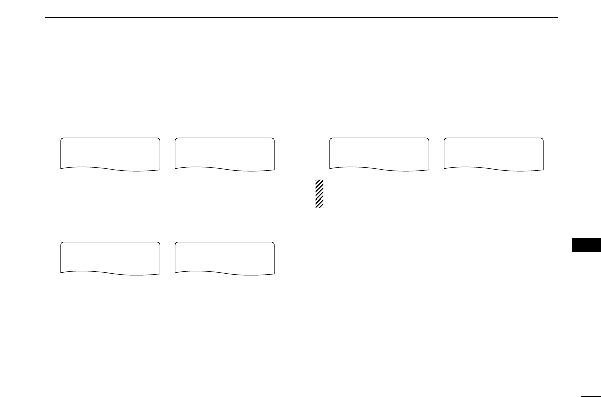
93
11
MENU SCREEN OPERATION
1
2
3
4
5
6
7
8
9
10
11
12
13
14
15
16
17
18
19
DDDigital repeater setting
When accessing the repeater’s call sign is different as your
programmed, the repeater call sign can be stored into “RPT1”
and/or “RPT2” automatically by reading the repeater’s trans-
mission. The stored repeater’s call sign can be re-called when
selecting the repeater call sign. (default: ON)
DDRX call sign auto write
When an individual station call is received, the calling station
call sign can be set for operation automatically.
(default: OFF)
DDRepeater call sign auto write
When accessing the repeater’s call sign is different as your
programmed, the repeater call sign can be stored into “RPT1”
and/or “RPT2” automatically by reading the repeater’s trans-
mission. The stored repeater’s call sign can be re-called when
selecting the repeater call sign. (default: OFF)
The transceiver stores the received repeater call sign into
repeater call sign memory only when the repeater’s call
sign has not been programmed in the memory.
OFFOFF
AUTOAUTO
RXRPT WRITE
r
OFFOFF
AUTOAUTO
RXRPT WRITE
r
OFFOFF
AUTOAUTO
RXCALL WRITE
r
OFFOFF
AUTOAUTO
RXCALL WRITE
r
ONON
OFFOFF
DIGITAL RPT SET
r
ONON
OFFOFF
DIGITAL RPT SET
r

94
11 MENU SCREEN OPERATION
DDGPS mode
Sets automatic position transmission function ON and OFF.
When the position information is received from a connected
GPS receiver and the GPS Auto TX Timer setting below is set
to a specific time, the transceiver automatically transmits with
the current position and message at every setting interval.
(default: OFF)
•Sentence formatter setting
qWhile selecting “GPS” setting item, push [5/SKIP](ï)†to
enter the sentence formatter setting condition.
wRotate [DIAL]†to select the desired sentence formatter
that you want to change setting.
•RMC, GGA, GLL, GSA and VTG are selectable.
ePush [5/SKIP](ï)†to enter the desired sentence formatter
setting condition.
rRotate [DIAL]†to select the setting.
tRotate [DIAL]†to select next sentence and repeat steps
wto r, or push [MENU/LOCK] to return to frequency in-
dication.
•Only three sentence formatters are activated at same time.
OFFOFF
ONON
RMC SENTENCE
r
OFFOFF
ONON
RMC SENTENCE
r
RMC:OFFRMC:OFF
GGA:ONGGA:ON
GLL:OFFGLL:OFF
GSA:OFFGSA:OFF
VTG:OFFVTG:OFF
GPS SENTENCE
r
RMC:OFFRMC:OFF
GGA:ONGGA:ON
GLL:OFFGLL:OFF
GSA:OFFGSA:OFF
VTG:OFFVTG:OFF
GPS SENTENCE
r
OFFOFF
ONON
:SENTENCE
GPS MODE
r
:SENTENCE
OFFOFF
ONON
GPS MODE
r

95
11
MENU SCREEN OPERATION
1
2
3
4
5
6
7
8
9
10
11
12
13
14
15
16
17
18
19
DDGPS auto TX timer
Sets the desired interval for automatic position transmission
function from 5, 10, 30 second, 1, 3, 5, 10 and 30 minutes.
(default: OFF)
DDDV auto detect
When a signal other than DV mode is received during DV
mode operation, the transceiver has capability of automatic
FM mode selection.
• OFF : Operating mode is fixed in DV. (default)
• ON : The transceiver automatically selects FM
mode for temporal operation.
DDCall sign edit record
Selects the call sign programming condition when the call
sign is edited or corrected with the pre-programmed call sign.
• OFF : The edited or corrected call sign is over writ-
ten.
• SELECT : The edited or corrected call sign is pro-
grammed into the selected call sign memory.
• AUTO : The edited or corrected call sign is pro-
grammed into a blank channel automatically.
(default)
AUTOAUTO
SELECTSELECT
OFFOFF
EDIT RECORD
r
AUTOAUTO
SELECTSELECT
OFFOFF
EDIT RECORD
r
OFFOFF
ONON
DV AUTO DETECTDV AUTO DETECT
r
OFFOFF
ONON
DV AUTO DETECT
r
OFFOFF
5SEC5SEC
10SEC10SEC
30SEC30SEC
1MIN1MIN
GPS AUTO TXGPS AUTO TX
r
OFFOFF
5SEC5SEC
10SEC10SEC
30SEC30SEC
1MIN1MIN
GPS AUTO TX
r
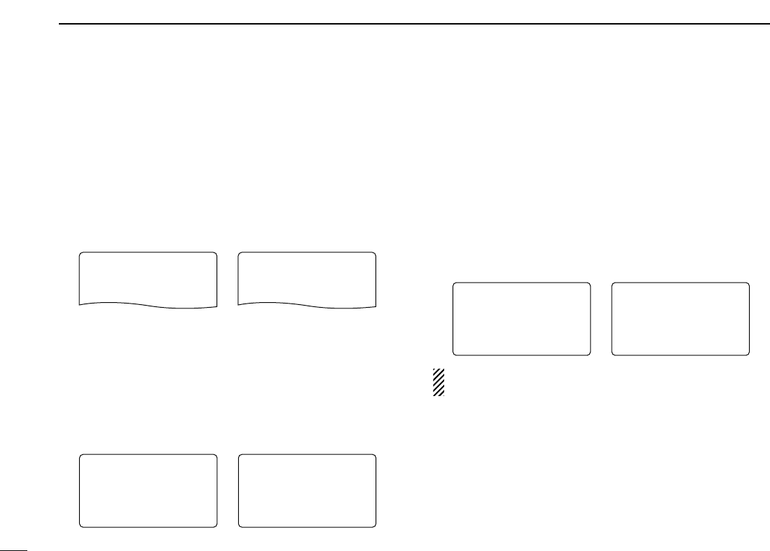
96
11 MENU SCREEN OPERATION
■Scan set mode items
DDPriority watch
Activates priority watch or priority watch with alert (Bell).
•OFF : The priority watch is turned OFF. (default)
•ON : The transceiver checks the memory channel fre-
quency every 5 sec.
•BELL : The transceiver checks the memory channel fre-
quency every 5 sec. You can be alerted with
beeps and blinking “S”.
DDScan pause timer
Selects the scan pause time. When receiving signals, the
scan pauses according to the scan pause time.
•2–20 SEC : Scan pauses for 2–20 sec. on a received
signal in 2 sec. steps. (default: 10 sec.)
•HOLD : Scan pauses on a received signal until it dis-
appears. Rotate [DIAL] to resume manually.
DDScan resume timer
Selects the scan resume time of a paused frequency after the
received signal disappears.
•0 : Scan resumes when a received signal disap-
pears.
•1–5 SEC : Scan pause 1–5 sec. after a received signal
disappears. (default: 2 sec.)
•HOLD : Scan pauses on the received signal even if it
disappears. Rotate [DIAL]†to resume manu-
ally.
Scan resume timer must be set shorter than scan pause
timer (previous item), otherwise this timer does not activate.
2SEC2SEC
4SEC4SEC
3SEC3SEC
1SEC1SEC
5SEC5SEC
RESUME TIMER
r
3SEC3SEC
5SEC5SEC
4SEC4SEC
2SEC2SEC
HOLDHOLD
RESUME TIMER
r
10SEC10SEC
6SEC6SEC
8SEC8SEC
4SEC4SEC
12SEC12SEC
PAUSE TIMER
r
20SEC20SEC
16SEC16SEC
18SEC18SEC
14SEC14SEC
HOLDHOLD
PAUSE TIMER
r
OFFOFF
ONON
BELLBELL
PRIO WATCHPRIO WATCH
r
OFFOFF
ONON
BELLBELL
PRIO WATCH
r

97
11
MENU SCREEN OPERATION
1
2
3
4
5
6
7
8
9
10
11
12
13
14
15
16
17
18
19
DDMemory bank link function
Sets the memory bank link function ON (default) and OFF. The
link function provides continuous bank scan, scanning all con-
tents in the selected banks during bank scan.
•Bank link setting
qRotate [DIAL]†to select the bank that you want to change
setting.
wPush [5/SKIP](ï)†to enter the bank setting condition.
eRotate [DIAL]†to select the setting.
rPush [5/SKIP](ï)†to set and return to the BANK LINK
screen.
tRotate [DIAL]† to select next bank and repeat steps wto
r, or push [MENU/LOCK] to exit scan set mode.
■DUP/TONE set mode items
DDOffset frequency
Sets the offset frequency for duplex (repeater) operation within
0 to 159.995 MHz range.
The default value may differ according to the selected fre-
quency band (before accessing DUP/TONE set mode) and trans-
ceiver version.
The selected tuning step in VFO mode is used for setting
the offset frequency.
DDRepeater tone frequency
Selects subaudible tone frequency for accessing a repeater,
etc. Total of 50 tone frequencies (67.0–254.1 Hz) are available.
(default: 88.5)
88.5 88.5
REPEATER TONE
254.1254.1
REPEATER TONE
0.000.00 0.000.00
OFFSET FREQ
159.995.00159.995.00
OFFSET FREQ
ONON
OFFOFF
BANK-ABANK-A
r
ONON
OFFOFF
BANK-A
r
BANK-A:ONBANK-A:ON
BANK-D:ONBANK-D:ON
BANK-C:ONBANK-C:ON
BANK-B:ONBANK-B:ON
BANK-E:ONBANK-E:ON
BANK LINKBANK LINK
r
BANK-V:ONBANK-V:ON
BANK-Y:ONBANK-Y:ON
BANK-X:ONBANK-X:ON
BANK-W:ONBANK-W:ON
BANK-Z:ONBANK-Z:ON
BANK LINK
\
r
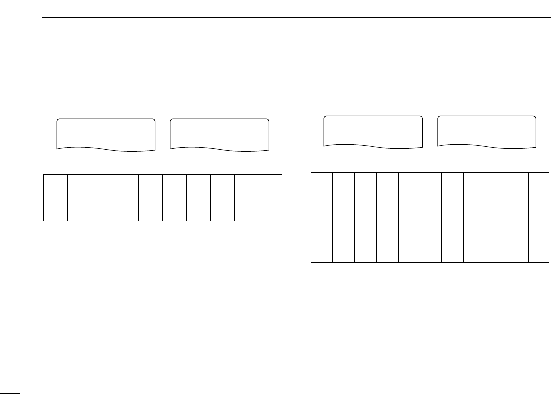
98
11 MENU SCREEN OPERATION
DDTSQL frequency
Selects tone frequency for tone squelch or pocket beep oper-
ation from one of 50 available frequencies (67.0–254.1 Hz).
(default: 88.5)
•Available subaudible tone frequencies
DDDTCS code
Selects DTCS (both encoder/decoder) code for DTCS squelch
operation. Total of 104 codes (023–754) are available.
(default: 023)
•Available DTCS code
023
025
026
031
032
036
043
047
051
053
125
131
132
134
143
145
152
155
156
162
245
246
251
252
255
261
263
265
266
271
356
364
365
371
411
412
413
423
431
432
506
516
523
526
532
546
565
606
612
624
054
065
071
072
073
074
114
115
116
122
165
172
174
205
212
223
225
226
243
244
274
306
311
315
325
331
332
343
346
351
445
446
452
454
455
462
464
465
466
503
627
631
632
654
662
664
703
712
723
731
732
734
743
754
023023
DTCS CODE
754754
DTCS CODE
67.0
69.3
71.9
74.4
77.0
79.7
82.5
85.4
88.5
91.5
94.8
97.4
100.0
103.5
107.2
110.9
114.8
118.8
123.0
127.3
131.8
136.5
141.3
146.2
151.4
156.7
159.8
162.2
165.5
167.9
171.3
173.8
177.3
179.9
183.5
186.2
189.9
192.8
196.6
199.5
203.5
206.5
210.7
218.1
225.7
229.1
233.6
241.8
250.3
254.1
88.5 88.5
CTCSS TONECTCSS TONE
254.1254.1
CTCSS TONE

99
11
MENU SCREEN OPERATION
1
2
3
4
5
6
7
8
9
10
11
12
13
14
15
16
17
18
19
DDDTCS polarity
Sets DTCS polarity from “BOTH N” (TX/RX: normal), “TN-RR”
(TX: normal, RX: reverse), “TR-RN” (TX: reverse, RX: normal) and
“BOTH R” (TX/RX: reverse).(default: BOTH N)
DDDTMF speed
Select the desired DTMF transmission speed from 100 msec,
200 msec, 300 msec, 500 msec.
•100 : 100 msec. interval; 5.0 characters per second
(default)
•200 : 200 msec. interval; 2.5 characters per second
•300 : 300 msec. interval; 1.6 characters per second
•500 : 500 msec. interval; 1.0 character per second
■Display set mode items
DDDisplay backlighting
The transceiver has display backlighting with a 5 sec. timer
for night time operation. The display backlighting can be
turned ON continuously or turned OFF, if desired.
•OFF : The backlight is turned OFF.
•ON : The backlight continuously lights ON.
•AUTO: Lights when an operation is performed, goes out
after 5 sec. (default)
*Continuously lights ON while operating with an
external DC power source. (more than 10 V DC)
DDBusy LED
The TX/RX indicator lights green while receiving a signal or
when the squelch is open. This indication can be turned OFF
to conserve the battery power, if desired.
•OFF : The indicator does not function even if a signal is
received.
•ON : The indicator lights green while receiving a signal
or when the squelch is open. (default)
ONON
OFFOFF
BUSY LED
r
ONON
OFFOFF
BUSY LED
r
AUTOAUTO
ONON
OFFOFF
BACKLIGHT
r
AUTOAUTO
ONON
OFFOFF
BACKLIGHT
r
100100
200200
300300
500500
DTMF SPEEDDTMF SPEED
r
100100
200200
300300
500500
DTMF SPEED
r
TX/RX: Normal polarity TX/RX: Reverse polarity
BOTH NBOTH N
TN-RRTN-RR
TR-RNTR-RN
BOTH RBOTH R
DTCS POLARITYDTCS POLARITY
r
BOTH RBOTH R
TN-RRTN-RR
TR-RNTR-RN
BOTH NBOTH N
DTCS POLARITY
r

100
11 MENU SCREEN OPERATION
DDLCD contrast
The contrast of the LCD can be adjusted from 16 levels.
•1 (Low contrast) to 16 (High contrast) (default: 8)
DDRX Call Sign Display
☞Available for IC-91AD, or UT-121 is installed IC-91A only.
When an individual station call is received, the calling station
call sign can be indicated automatically. (default: AUTO)
DDTX Call Sign Display
☞Available for IC-91AD, or UT-121 is installed IC-91A only.
Selects call sign display function from YOUR, MY and OFF.
When this setting is set to YOUR or MY, the transceiver auto-
matically indicates the set station or your own call sign at dig-
ital mode transmission. (default: YOUR)
DDRX message Display
☞Available for IC-91AD, or UT-121 is installed IC-91A only.
Sets auto received message display function AUTO and OFF.
When this setting is set to AUTO, the transceiver automati-
cally indicates and scrolls the received message.
(default: AUTO)
AUTOAUTO
OFFOFF
RX MESSAGE
r
AUTOAUTO
OFFOFF
RX MESSAGE
r
YOURYOUR
MYMY
OFFOFF
TX CALL SIGN
r
YOURYOUR
MYMY
OFFOFF
TX CALL SIGN
r
AUTOAUTO
OFFOFF
RX CALL SIGN
r
AUTOAUTO
OFFOFF
RX CALL SIGN
r
LCD CONTRASTLCD CONTRAST LCD CONTRAST
High contrast (16)Default (8)

101
11
MENU SCREEN OPERATION
1
2
3
4
5
6
7
8
9
10
11
12
13
14
15
16
17
18
19
DDScan name
The programmed scan or bank name is displayed during the
programmed scan edge or bank channel selection.
•ON : The programmed scan or bank name is dis-
played. (default)
•OFF : The programmed scan or bank name is not dis-
played.
DDOpening logo
The opening logo indication (Icom logo and transceiver name)
that is displayed at power ON can be skipped, if desired.
• ON : Opening logo is displayed at power ON. (default)
• OFF : Opening logo indication is skipped.
DDOpening call sign
☞Available for IC-91AD, or UT-121 is installed IC-91A only.
The set your own call sign, programmed in my call sign, can
be displayed at power ON. (default: OFF)
DDFont size
Displayed character size during MENU mode indication in the
function display is selectable from Large and Small.
• LARGE : Makes 5 lines (Max. 5 items are displayed at the
same time). (default)
• SMALL : Makes 6 lines (Max. 6 items are displayed at the
same time).
LARGELARGE
SMALLSMALL
FONT SIZE
r
SMALL
LARGE
FONT SIZE
r
OFFOFF
ONON
OPENING CALL S
r
ONON
OFFOFF
OPENING CALL S
r
ONON
OFFOFF
OPENING LOGO
r
OFFOFF
ONON
OPENING LOGO
r
ONON
OFFOFF
SCAN NAME
r
ONON
OFFOFF
SCAN NAME
r
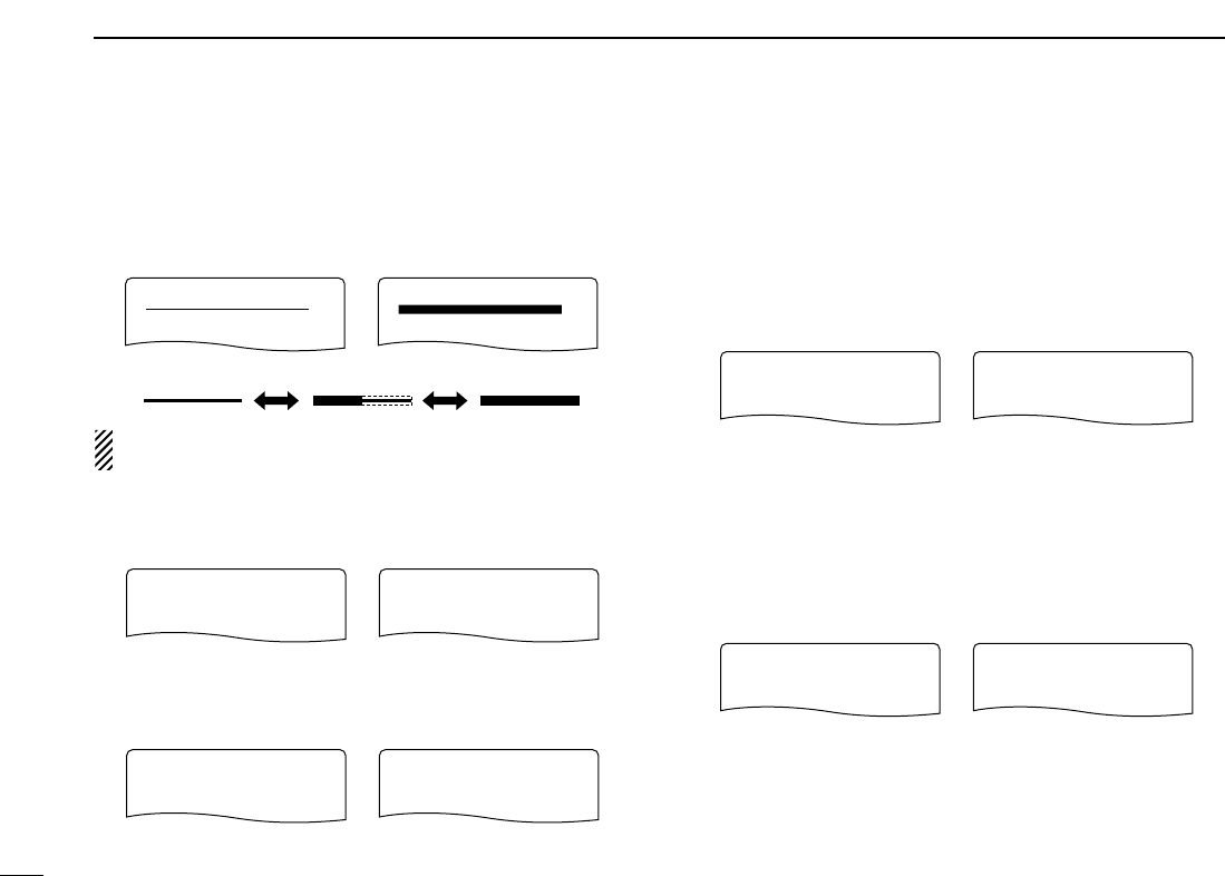
102
11 MENU SCREEN OPERATION
■Sounds set mode items
DDBeep output level
Adjusts the key-touch beep tone level to the desired level
within 39 levels.
The key-touch beep (below item) must be set to ON to have
a beep tone.
DDKey-touch beep
Turns the key-touch beep ON or OFF. (default: ON)
DDScan stop beep
Turns the scan stop beep function ON or OFF. (default: OFF)
DDScope audio output
Select the audio output function capability during sweep with
band scope function.
•ON : The received audio sounds during sweep. (de-
fault)
•OFF : No audio sounds during sweep.
DDVolume select
Select the volume level adjustment from Both and Separate.
•BOTH : Both A and B bands volume level is ad-
justed with [VOL] at the same time.
(default)
•SEPARATE : The Volume setting is adjusted indepen-
dently in A and B bands with [VOL].
BOTHBOTH
SEPARATESEPARATE
VOLUME SELECT
r
SEPARATESEPARATE
BOTHBOTH
VOLUME SELECT
r
ONON
OFFOFF
SCOPE AF OUTPUT
r
OFFOFF
ONON
SCOPE AF OUTPUT
r
OFFOFF
ONON
SCAN STOP BEEP
r
ONON
OFFOFF
SCAN STOP BEEP
r
ONON
OFFOFF
KEY-TOUCH BEEP
r
OFFOFF
ONON
KEY-TOUCH BEEP
r
BEEP LEVELBEEP LEVEL BEEP LEVEL
Minimum level (no audio) Maximum level

103
11
MENU SCREEN OPERATION
1
2
3
4
5
6
7
8
9
10
11
12
13
14
15
16
17
18
19
DDStandby Beep
☞Available for IC-91AD, or UT-121 is installed IC-91A only.
Turns the beep emission capability ON and OFF when the
communicating station finishes transmitting or the receive sig-
nal disappears while in the digital mode operation.
(default: ON)
ONON
OFFOFF
STANDBY BEEP
r
OFFOFF
ONON
STANDBY BEEP
r
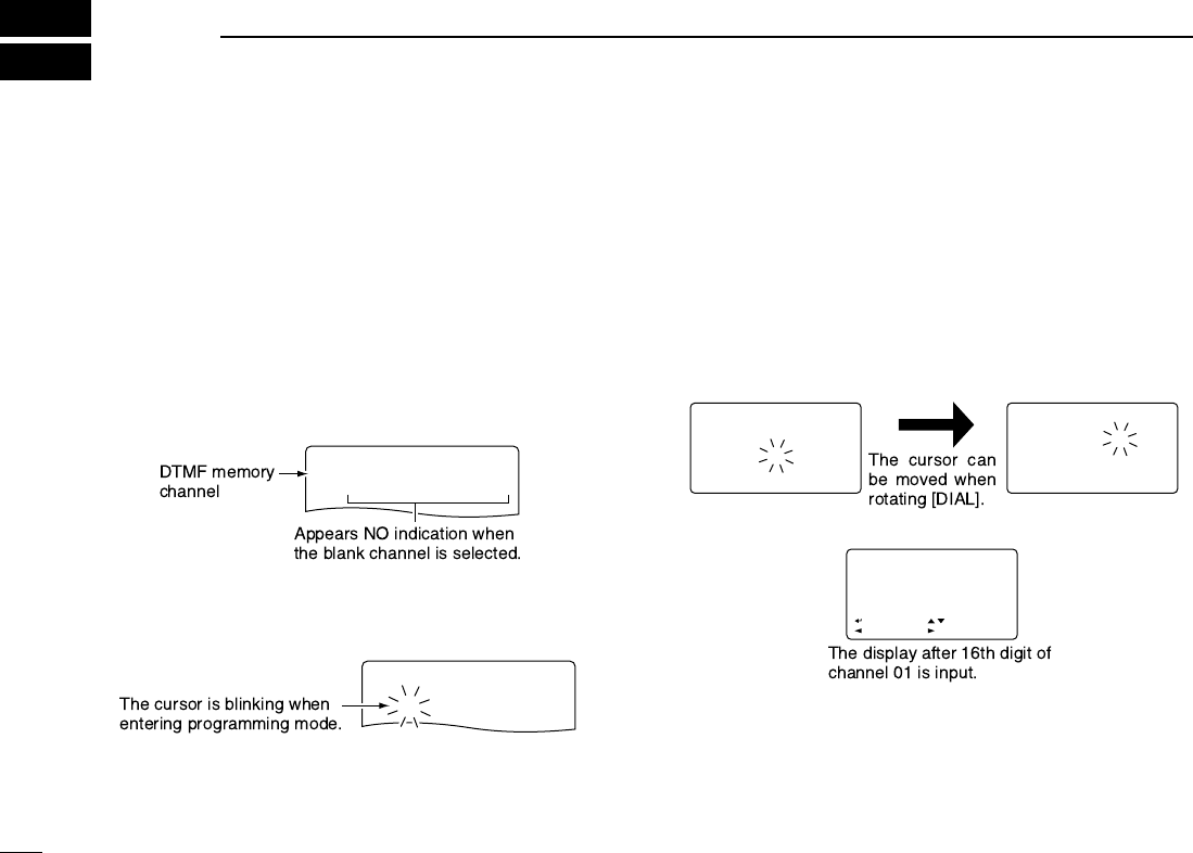
104
OTHER FUNCTIONS
12
■Programming a DTMF code
DTMF codes are used for autopatching, accessing repeaters,
controlling other equipment, etc. The transceiver has 10
DTMF memory channels (Ch01–Ch10) for storage of often-
used DTMF codes of up to 16 digits.
qPush and hold [./EMR/DTMF.M](#) for 1 sec. to enter
DTMF memory.
wRotate [DIAL]†to select the desired DTMF memory chan-
nel.
•“T-CALL” appears when a 1750 Hz tone burst signal is selected.
(p. ??)
ePush and hold [6/M.N](≈≈)for 1 sec. to enter programming
mode.
•Previously programmed DTMF code is cleared.
rPush the desired keys to input the characters.
•[VFO/MHz](A) inputs “A,”[MR/S.MW](B) inputs “B,”
[CALL/RX➝CS](C) inputs “C,”[BAND](D) inputs “D,”
[./EMR/DTMF.M](#) inputs “#” and [REC/MODE](✱)inputs “✱”.
•Up to 16 digits can be programmed.
•Push [MAIN/DUAL] to delete the cursor placed code.
•Push and hold [MAIN/DUAL] for 1 sec. to delete the cursor
placed or later codes.
tRepeat step runtil the desired code is input.
yPush [MENU/LOCK] to program the DTMF code and exit
programming mode.
•Entering 16th digit automatically exits the programming mode.
r
Ch01
DTMF MEMORY
r
Ch01
6
DTMF MEMORY
Ch01Ch01
01234567 01234567
89ABC*#0 89ABC*#0
:SET
:BACK
:SEL
:EDIT
DTMF MEMORY
r
Ch01Ch01
01234567 01234567
89AB 89AB
6
SQL:SET MAIN:CLR SQL:SET MAIN:CLR
DTMF MEMORY
r
Ch01Ch01
012345 012345
6
7
89AB 89AB
DTMF MEMORY
r
r
Ch01
DTMF MEMORY
r
Ch01Ch01
6
DTMF MEMORY
Ch01
01234567
89ABC*#0
:SET
:BACK
:SEL
:EDIT
DTMF MEMORY
Ch01
01234567
89AB
6
SQL:SET MAIN:CLR SQL:SET MAIN:CLR
DTMF MEMORY
Ch01
012345
6
7
89AB
DTMF MEMORY
r
Ch01Ch01
DTMF MEMORY
r
Ch01
6
DTMF MEMORY
Ch01
01234567
89ABC*#0
:SET
:BACK
:SEL
:EDIT
DTMF MEMORY
Ch01
01234567
89AB
6
SQL:SET MAIN:CLR SQL:SET MAIN:CLR
DTMF MEMORY
Ch01
012345
6
7
89AB
DTMF MEMORY
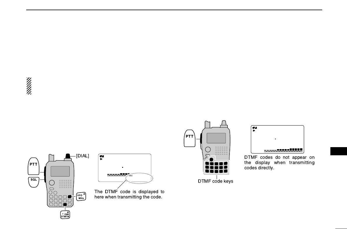
105
12
OTHER FUNCTIONS
1
2
3
4
5
6
7
8
9
10
11
12
13
14
15
16
17
18
19
■Transmitting a DTMF code
DTransmitting from DTMF memory
The selected DTMF code is transmitted at each push of the
[SQL] switch while transmitting.
The transmitting speed at which DTMF memories send in-
dividual DTMF characters can be set in “DTMF SPEED”
menu. (p. ??)
qSet the desired frequency. (p. ??)
wPush and hold [./EMR/DTMF.M](#) for 1 sec. to enter
DTMF memory.
eRotate [DIAL]†to select the desired DTMF memory chan-
nel.
rPush [VFO/MHz] to exit DTMF memory.
tWhile pushing [PTT], push [SQL] to transmit the selected
DTMF code.
DTransmitting a DTMF code directly
DTMF code can be transmitted via keypad directly while
transmitting.
qSet the desired frequency. (p. ??)
wWhile pushing [PTT], push the desired keys to transmit the
DTMF code.
•[0/CQ]–[9/BK/T.SCAN] input “0”–“9,” [VFO/MHz](A) inputs “A,”
[MR/S.MW](B) inputs “B,”[CALL/RX➝CS](C) inputs “C,”
[BAND](D) inputs “D,” [./EMR/DTMF.M](#) inputs “#” and
[REC/MODE](✱)inputs “✱.”
MemoName
PRIO WX EMR
DTCS
FM
A
438500
PSKIP
+DUP
25
µ
000
5D28AB4
A
FM
438500
PSKIP
MemoName
PRIOPRIO WXWX EMREMR
DTCSDTCS
FMFM
A
438500
PSKIPPSKIP
+DUP+DUP
25
µ
000
5D28AB45D28AB4
A
FM
438500
P SKIP
†[DIAL] ↔[2/SCAN](∫∫)/[8/TS](√√) [5/SKIP](ï)↔[6/M.N](≈≈)
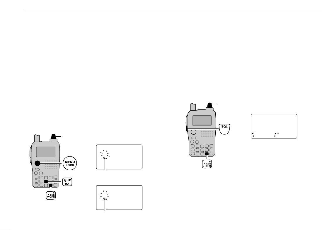
106
12 OTHER FUNCTIONS
■Clearing a DTMF memory
An unwanted DTMF memory can be cleared (erased).
qPush and hold [./EMR/DTMF.M](#) for 1 sec. to enter
DTMF memory mode.
wRotate [DIAL]†to select the desired DTMF memory chan-
nel to be cleared.
ePush [6/M.N](≈≈)to enter programming mode, and rotate
[DIAL] to set cursor to 1st digit.
rPush and hold [MAIN/DUAL] for 1 sec. to clear the se-
lected DTMF memory channel.
•The DTMF memory channel is cleared.
tPush [MENU/LOCK] to exit programming mode.
■Confirming a DTMF memory
The DTMF memory can be confirmed with a DTMF tone.
qPush and hold [./EMR/DTMF.M](#) for 1 sec. to enter
DTMF memory mode.
wRotate [DIAL]†to select the desired DTMF memory chan-
nel.
ePush [SQL] to confirm the DTMF memory contents.
Push [SQL], then sounds DTMF
codes.
Ch01
6
1234567
89AB
SQL:BACK MAIN:CLR
DTMF MEMORY
Ch01
6
SQL:BACK MAIN:CLR
DTMF MEMORY
[DIAL]
Ch01Ch01
01234567 01234567
89ABC*#0 89ABC*#0
:SET
:BACK
:SEL
:EDIT
DTMF MEMORY
r
[DIAL] •
•
The cursor is blinking.
The cursor is blinking.
When entering DTMF programming
mode.
After clearing the DTMF memory.
Ch01Ch01
6
12345671234567
89AB 89AB
SQL:BACKSQL:BACK MAIN:CLRMAIN:CLR
DTMF MEMORY
r
Ch01Ch01
6
SQL:BACKSQL:BACK MAIN:CLRMAIN:CLR
DTMF MEMORY
r
Ch01
01234567
89ABC*#0
:SET
:BACK
:SEL
:EDIT
DTMF MEMORY

107
12
OTHER FUNCTIONS
1
2
3
4
5
6
7
8
9
10
11
12
13
14
15
16
17
18
19
■Setting DTMF transferring
speed
The DTMF transferring speed can be selected.
qEnter “DTMF SPEED” in DUP/TONE... set mode. (p. ??)
wRotate [DIAL]†to select DTMF transferring speed as
below.
100: Transfer the DTMF data per about 100 msec.
200: Transfer the DTMF data per about 200 msec.
300: Transfer the DTMF data per about 300 msec.
500: Transfer the DTMF data per about 500 msec.
ePush [5/SKIP](ï)to set DTMF transferring speed and
push [MENU/LOCK] to return to frequency indication.
■Tone frequency and DTCS
code
DSubaudible (repeater) tone
Some repeaters require subaudible tones to be accessed.
Subaudible tones are superimposed over your normal signal
and must be set in advance.
DTone and DTCS squelches
The tone squelch (CTCSS) or DTCS squelch opens only
when receiving a signal containing a matching subaudible
tone or DTCS code, respectively. You can silently wait for
calls from group members using the same tone or code. Sep-
arate tone frequencies can be set for repeater and tone
squelch/pocket beep operation.
DPocket beep
These functions use subaudible tones or DTCS codes for
calling and can be used as a “common pager” to inform you
that someone has called while you were away from the trans-
ceiver. The same code is used for DTCS squelch and beep.
MENU screen➪DUP/TONE...➪DTMF SPEED
(Push [MENU/LOCK]) (Rotate [DIAL]†, then push [5/SKIP](ï)†.)
DV SET MODE
SCAN
r
DUP/TONE...
***** MENU *****
r
100100
200200
500500
300300
DTMF SPEED
†[DIAL] ↔[2/SCAN](∫∫)/[8/TS](√√) [5/SKIP](ï)↔[6/M.N](≈≈)

108
12 OTHER FUNCTIONS
■TONE FREQUENCY AND DTCS CODE (Continued)
D
Setting subaudible tones for repeater or tone
squelch
qEnter “CTCSS TONE” in DUP/TONE… (or RPT TONE) set
mode. (p. ??)
wRotate [DIAL]†to select the desired repeater or CTCSS
tone frequency.
•Each operating band and each memory channel have indepen-
dent settings.
ePush [5/SKIP](ï)to set repeater or CTCSS tone fre-
quency and push [MENU/LOCK] to return to frequency in-
dication.
DSetting DTCS code for DTCS squelch or
beep
qEnter “DTCS TONE” in DUP/TONE... set mode. (p. ??)
wRotate [DIAL]†to select the desired DTCS tone code.
•Each operating band and each memory channel have indepen-
dent settings.
ePush [5/SKIP](ï)to set DTCS tone code and push
[MENU/LOCK] to return to frequency indication.
DTCS phase mode can be selected in “DTCS POLARITY”
menu. (p. ??)
DV SET MODE
SCAN
r
DUP/TONE...
***** MENU *****
88.5
200
500
r
300
CTCSS TONE
88.5
200
500
r
300
REPEATER TONE
DV SET MODE
SCAN
r
DUP/TONE...
***** MENU *****
023023
200200
500500
r
300300
DTCS TONE
MENU screen➪DUP/TONE...➪DTCS TONE
(Push [MENU/LOCK]) (Rotate [DIAL]†, then push [5/SKIP](ï)†.)
DV SET MODE
SCAN
r
DUP/TONE...
***** MENU *****
88.588.5
200200
500500
r
300300
CTCSS TONECTCSS TONE
88.588.5
200200
500500
r
300300
REPEATER TONE
DV SET MODE
SCAN
r
DUP/TONE...
***** MENU *****
023
200
500
r
300
DTCS TONE
MENU screen➪DUP/TONE...➪CTCSS TONE
(Push [MENU/LOCK]) (Rotate [DIAL]†, then push [5/SKIP](ï)†.)

109
12
OTHER FUNCTIONS
1
2
3
4
5
6
7
8
9
10
11
12
13
14
15
16
17
18
19
D
Setting digital code
for digital code squelch
or beep
qPush [MAIN/DUAL] to select B band, then push and hold
[REC/MODE] for 1 sec. several times to select DV mode.
wEnter “DIGITAL CODE” in DV SET MODE.(p. ??)
eRotate [DIAL]†to select the desired digital code.
•Each operating band and each memory channel have indepen-
dent settings.
rPush [5/SKIP](ï)to set digital code and push
[MENU/LOCK] to return to frequency indication.
DSetting the your and my call signs for call
sign squelch or beep
qPush [MAIN/DUAL] to select B band, then and hold
[REC/MODE] for 1 sec. several times to select DV mode.
wEnter “YOUR CALL SIGN” in CALL SIGN set mode. (p. ??)
eRotate [DIAL]†to select the desired call sign.
•Input the call sign if the desired call sign is not registered in the
transceiver. See p. ?? for detail.
rPush [5/SKIP](ï)to set call sign and return to “CALL
SIGN” in menu screen.
Continue to the next page.
DV VOICE M
SET MODE
r
DV SET MODE
***** MENU *****
00
200
500
r
300
DIGITAL CODE
r
CALL SIGN
RX CALL S
MESSAGE/POS
***** MENU *****
r
U01U01
ABCDEFABCDEF
500500
r
300300
YOUR CALL SIGN
r
M01
GHIJKL
500
r
300
MY CALL SIGN
MENU screen➪CALL SIGN➪YOUR CALL SIGN
(Push [MENU/LOCK]) (Rotate [DIAL]†, then push [5/SKIP](ï)†.)
DV VOICE M
SET MODE
r
DV SET MODE
***** MENU *****
0000
200200
500500
r
300300
DIGITAL CODE
r
CALL SIGN
RX CALL S
MESSAGE/POS
***** MENU *****
r
U01
ABCDEF
500
r
300
YOUR CALL SIGN
r
M01
GHIJKL
500
r
300
MY CALL SIGN
MENU screen➪DV SET MODE➪DIGITAL CODE
(Push [MENU/LOCK]) (Rotate [DIAL]†, then push [5/SKIP](ï)†.)
■Digital code and call sign setting The optional UT-121 is required for IC-91A
†[DIAL] ↔[2/SCAN](∫∫)/[8/TS](√√) [5/SKIP](ï)↔[6/M.N](≈≈)

110
12 OTHER FUNCTIONS
DSetting the your and my call signs for call sign squelch or
beep (Continued)
tRotate [DIAL]†to select “MY CALL SIGN” in CALL SIGN
set mode, then push [5/SKIP](ï)†to enter “MY CALL
SIGN” setting.
yRotate [DIAL]†to select the desired call sign.
•Input the call sign if the desired call sign is not registered in the
transceiver. See p. ?? for detail.
uPush [5/SKIP](ï)†to set call sign and push
[MENU/LOCK] to return to frequency indication.
CAUTION!: Use digital code squelch function when operat-
ing with more than 3 stations. Because the digital call sign
squelch function recognizes “MY CALL SIGN”. Therefore,
the digital call sign squelch function can be used when op-
erating with only one station.
NOTE:
• The tone/DTCS code squelch opens sometimes when
other stations communicate with adjacent tone frequency
or DTCS code.
• Sounds no audio with S-meter swing when receiving a sig-
nal which is not included in “MY CALL SIGN” on DV
mode.
DV VOICE M
SET MODE
r
DV SET MODE
***** MENU *****
00
200
500
r
300
DIGITAL CODE
r
CALL SIGN
RX CALL S
MESSAGE/POS
***** MENU *****
r
U01
ABCDEF
500
r
300
YOUR CALL SIGN
r
M01
M01
GHIJKL
GHIJKL
500
500
r
300
300
MY CALL SIGN
MENU screen➪CALL SIGN➪MY CALL SIGN
(Push [MENU/LOCK]) (Rotate [DIAL]†, then push [5/SKIP](ï)†.)
†[DIAL] ↔[2/SCAN](∫∫)/[8/TS](√√) [5/SKIP](ï)↔[6/M.N](≈≈)
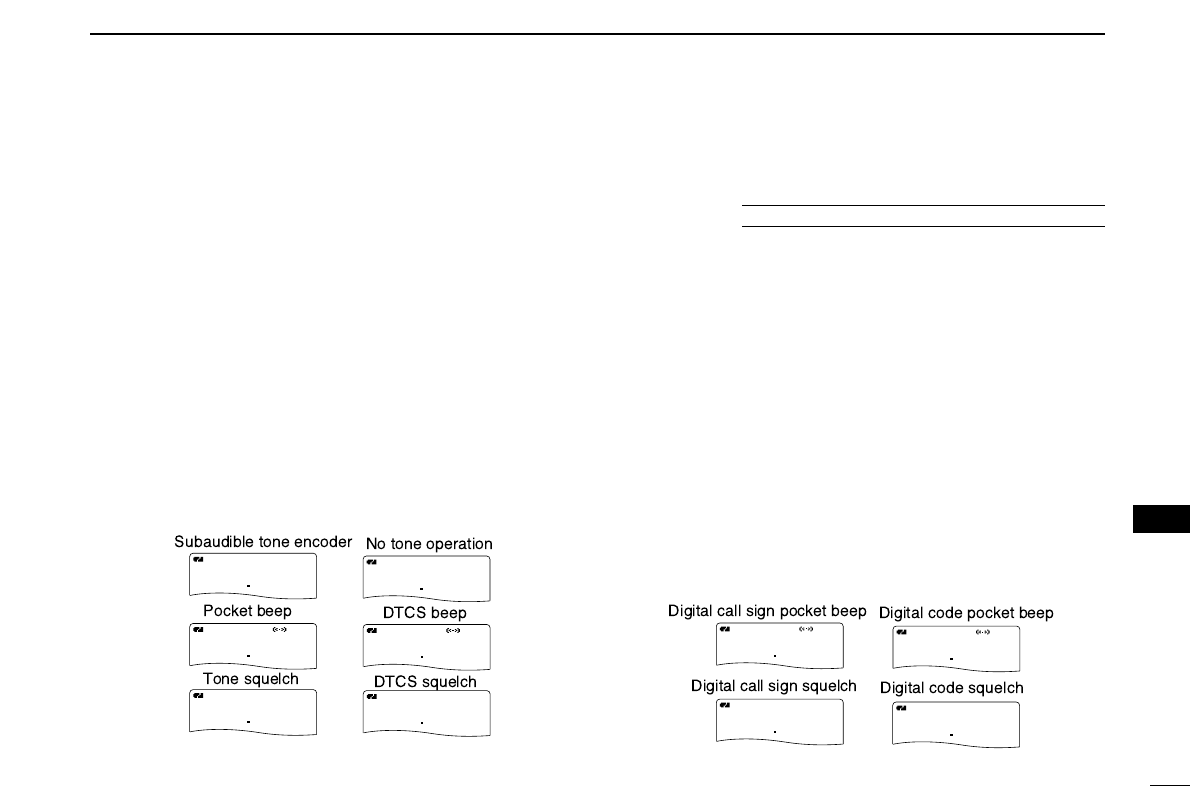
111
12
OTHER FUNCTIONS
1
2
3
4
5
6
7
8
9
10
11
12
13
14
15
16
17
18
19
■Tone/DTCS squelch
qSet the desired operating frequency, CTCSS tone and
DTCS code.
wPush and hold [7/DSQ/TONE] for 1 sec. several times to
activate the tone or DTCS squelch. (TONE, TSQL or
DTCS)
•Subaudible tone encoder “TONE,” tone squelch “TSQL,” pocket
beep “TSQLS,” DTCS squelch “DTCS,” DTCS beep
“DTCSS” and no tone operation are activated in order.
•Rotating [DIAL] while pushing [7/DSQ/TONE] also selects the
tone functions.
eOperate the transceiver in the normal way.
rWhen the received signal includes a matching tone/code,
the squelch opens and the signal can be heard.
•When the received signal’s tone/code does not match,
tone/DTCS squelch does not open, however, the S-indicator
shows signal strength.
•To open the squelch manually, push and hold [SQL].
■Digital code/digital call sign
squelch
qSet the desired operating frequency on DV mode, Digital
code and my call sign.
wPush and hold [7/DSQ/TONE] for 1 sec. several times to
activate the digital code or digita call signl squelch. (DSQL
or CSQL)
•Digital call sign squelch “DSQL,” Digital call sign beep
“DSQLS”, Digital code squelch “CSQL,” Digital code beep
“CSQLS” and no tone operation are activated in order.
•Rotating [DIAL] while pushing [7/DSQ/TONE] also selects the
tone functions.
eOperate the transceiver in the normal way.
rWhen the received signal includes a matching call
sign/code, the squelch opens and the signal can be heard.
•When the received signal’s call sign/code does not match, digital
call sign/digital code squelch does not open, however, the S-in-
dicator shows signal strength.
•To open the squelch manually, push and hold [SQL].
B
MemoName
PRIO WX EMR
DTCS
FM
145300
PSKIP
+DUP
25
B
MemoName
PRIO WX EMR
TONE
FM
145300
PSKIP
+DUP
25
B
MemoName
PRIO WX EMR
TSQL
FM
145300
PSKIP
+DUP
25
B
MemoName
PRIO WX EMR
DTCS
FM
145300
PSKIP
+DUP
25
B
MemoName
PRIO WX EMR
TSQL
FM
438500
PSKIP
+DUP
25
B
MemoName
PRIO WX EMR
DTCS
FM
438500
PSKIP
+DUP
25
B
MemoName
PRIO WX EMR
DTCS
FM
145300
PSKIP
+DUP
25
B
MemoName
PRIO WX EMR
TSQL
FM
145300
PSKIP
+DUP
25
B
MemoNameMemoName
PRIOPRIO WXWX EMREMR
DSQLDSQL
DVDV
145300
PSKIPPSKIP
+DUP+DUP
2525
B
MemoNameMemoName
PRIOPRIO WXWX EMREMR
CSQLCSQL
DVDV
145300
PSKIPPSKIP
+DUP+DUP
2525
B
MemoNameMemoName
PRIOPRIO WXWX EMREMR
DSQLDSQL
DVDV
145300
PSKIPPSKIP
+DUP+DUP
2525
B
MemoNameMemoName
PRIOPRIO WXWX EMREMR
CSQLCSQL
DVDV
145300
PSKIPPSKIP
+DUP+DUP
2525
B
MemoName
PRIO WX EMR
DSQL
DV
438500
PSKIP
+DUP
25
B
MemoName
PRIO WX EMR
CSQL
DV
438500
PSKIP
+DUP
25
The optional UT-121 is required for IC-91A
B
MemoNameMemoName
PRIOPRIO WXWX EMREMR
DTCSDTCS
FMFM
145300
PSKIPPSKIP
+DUP+DUP
2525
B
MemoNameMemoName
PRIOPRIO WXWX EMREMR
TONETONE
FMFM
145300
PSKIPPSKIP
+DUP+DUP
2525
B
MemoNameMemoName
PRIOPRIO WXWX EMREMR
TSQLTSQL
FMFM
145300
PSKIPPSKIP
+DUP+DUP
2525
B
MemoNameMemoName
PRIOPRIO WXWX EMREMR
DTCSDTCS
FMFM
145300
PSKIPPSKIP
+DUP+DUP
2525
B
MemoName
PRIO WX EMR
TSQL
FM
438500
PSKIP
+DUP
25
B
MemoName
PRIO WX EMR
DTCS
FM
438500
PSKIP
+DUP
25
B
MemoNameMemoName
PRIOPRIO WXWX EMREMR
DTCSDTCS
FMFM
145300
PSKIPPSKIP
+DUP+DUP
2525
B
MemoNameMemoName
PRIOPRIO WXWX EMREMR
TSQLTSQL
FMFM
145300
PSKIPPSKIP
+DUP+DUP
2525
B
MemoName
PRIO WX EMR
DSQL
DV
145300
PSKIP
+DUP
25
B
MemoName
PRIO WX EMR
CSQL
DV
145300
PSKIP
+DUP
25
B
MemoName
PRIO WX EMR
DSQL
DV
145300
PSKIP
+DUP
25
B
MemoName
PRIO WX EMR
CSQL
DV
145300
PSKIP
+DUP
25
B
MemoName
PRIO WX EMR
DSQL
DV
438500
PSKIP
+DUP
25
B
MemoName
PRIO WX EMR
CSQL
DV
438500
PSKIP
+DUP
25
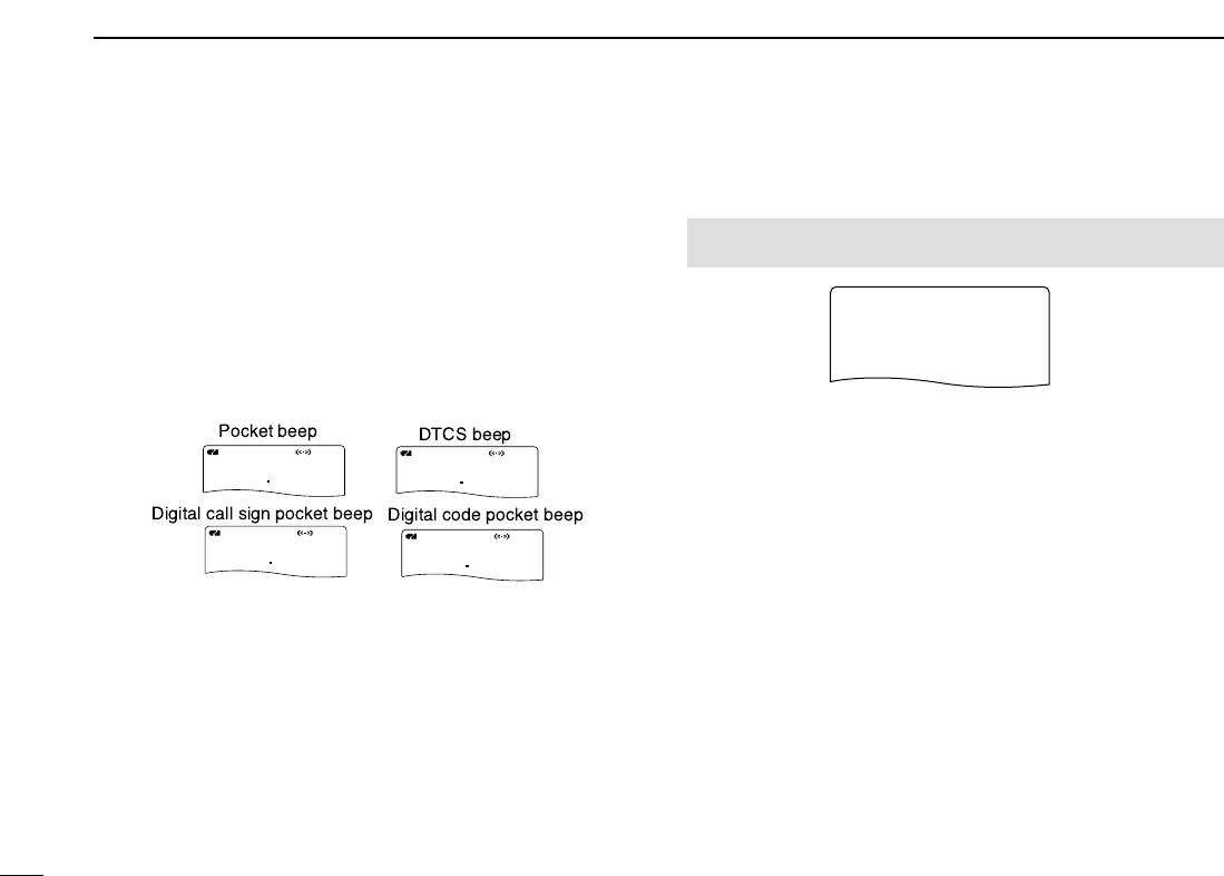
112
12 OTHER FUNCTIONS
■Pocket beep function
qSet the desired operating frequency.
wSet the desired CTCSS tone, DTCS code, Digital call sign
or Digital code.
ePush and hold [7/DSQ/TONE] for 1 sec. several times to
activate the pocket beep, DTCS beep, Digital call sign
beep or Digital code beep. (TSQLS, DTCS S,
DSQLSor CSQLS)
•Rotating [DIAL] while pushing [7/DSQ/TONE] also selects the
tone functions.
rWhen a signal with the correct tone, code, digital call sign
or digital code is received, the transceiver emits beep
tones for 30 sec. and blinks “S.”
tPush [PTT] to answer or push [SQL] to stop the beeps
and blinking.
■DTCS polarity setting
qEnter “DTCS P” in DUP/TONE... set mode. (p. ??)
wRotate [DIAL]†to select the desired DTCS porarity mode.
• BOTH H: Normal pahses are used for both TX and
RX. (Default)
• TN-RR: Normal pahse is used for TX; Reverse
phase for RX.
• TR-RN: Reverse pahse is used for TX; Normal
phase for RX.
• BOTH R: Reverse pahses are used for both TX and
RX.
ePush [5/SKIP](ï)to set repeater or CTCSS tone fre-
quency and push [MENU/LOCK] to return to frequency in-
dication.
r
RPT TONERPT TONE
CTCSS TONECTCSS TONE
r
DTCS CODEDTCS CODE
DUP/TONE...
r
DTCS PDTCS P
MENU screen➪DUP/TONE...➪DTCS P
(Push [MENU/LOCK]) (Rotate [DIAL]†, then push [5/SKIP](ï)†.)
B
MemoName
PRIO WX EMR
DTCS
FM
145300
PSKIP
+DUP
25
B
MemoName
PRIO WX EMR
TONE
FM
145300
PSKIP
+DUP
25
B
MemoName
PRIO WX EMR
TSQL
FM
145300
PSKIP
+DUP
25
B
MemoName
PRIO WX EMR
DTCS
FM
145300
PSKIP
+DUP
25
B
MemoNameMemoName
PRIOPRIO WXWX EMREMR
TSQLTSQL
FMFM
438500
PSKIPPSKIP
+DUP+DUP
2525
B
MemoNameMemoName
PRIOPRIO WXWX EMREMR
DTCSDTCS
FMFM
438500
PSKIPPSKIP
+DUP+DUP
2525
B
MemoName
PRIO WX EMR
DTCS
FM
145300
PSKIP
+DUP
25
B
MemoName
PRIO WX EMR
TSQL
FM
145300
PSKIP
+DUP
25
B
MemoName
PRIO WX EMR
DSQL
DV
145300
PSKIP
+DUP
25
B
MemoName
PRIO WX EMR
CSQL
DV
145300
PSKIP
+DUP
25
B
MemoName
PRIO WX EMR
DSQL
DV
145300
PSKIP
+DUP
25
B
MemoName
PRIO WX EMR
CSQL
DV
145300
PSKIP
+DUP
25
B
MemoNameMemoName
PRIOPRIO WXWX EMREMR
DSQLDSQL
DVDV
438500
PSKIPPSKIP
+DUP+DUP
2525
B
MemoNameMemoName
PRIOPRIO WXWX EMREMR
CSQLCSQL
DVDV
438500
PSKIPPSKIP
+DUP+DUP
2525
†[DIAL] ↔[2/SCAN](∫∫)/[8/TS](√√) [5/SKIP](ï)↔[6/M.N](≈≈)
113
12
OTHER FUNCTIONS
1
2
3
4
5
6
7
8
9
10
11
12
13
14
15
16
17
18
19
DAvailable tone frequency
The transceiver has 50 tone frequencies for repeater and
tone squelch (CTCSS)/pocket beep operation. Separate tone
frequencies can be set for repeater and tone squelch/pocket
beep operation.
(unit: Hz)
The transceiver has 50 tone frequencies and consequently
their spacing is narrow compared with units having 38
tones. Therefore, some tone frequencies may receive in-
terference from adjacent tone frequencies.
DAvailable DTCS codes
The transceiver has 104 DTCS codes for DTCS squelch and
DTCS beep.
67.0
69.3
71.9
74.4
77.0
79.7
82.5
85.4
88.5
91.5
94.8
97.4
100.0
103.5
107.2
110.9
114.8
118.8
123.0
127.3
131.8
136.5
141.3
146.2
151.4
156.7
159.8
162.2
165.5
167.9
171.3
173.8
177.3
179.9
183.5
186.2
189.9
192.8
196.6
199.5
203.5
206.5
210.7
218.1
225.7
229.1
233.6
241.8
250.3
254.1
023
025
026
031
032
036
043
047
051
053
054
065
071
072
073
074
114
115
116
122
125
131
132
134
143
145
152
155
156
162
165
172
174
205
212
223
225
226
243
244
245
246
251
252
255
261
263
265
266
271
274
306
311
315
325
331
332
343
346
351
356
364
365
371
411
412
413
423
431
432
445
446
452
454
455
462
464
465
466
503
506
516
523
526
532
546
565
606
612
624
627
631
632
654
662
664
703
712
723
731
732
734
743
754
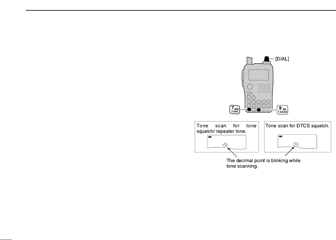
114
12 OTHER FUNCTIONS
■Tone scan
The transceiver can detect the subaudible tone frequency and
DTCS code in a received signal. By monitoring a signal that
is being transmitted on a repeater input frequency, you can
determine the tone frequency required to access the repeater.
qSet the desired frequency or memory channel to be
checked for a tone frequency or DTCS code.
wPush and hold [7/DSQ/TONE] for 1 sec. several times to
activate the repeater tone, tone squelch or DTCS squelch.
(TONE, TSQL or DTCS)
•Rotating [DIAL] while pushing and holding [7/DSQ/TONE] also
selects the tone functions.
ePush and hold [9/BK/T.SCAN] for 1 sec. to start the tone
scan.
•To change the scanning direction, rotate [DIAL].
rWhen the tone frequency or DTCS code is decoded, the
set mode contents are programmed with the frequency or
code.
•The tone scan pauses approx. 10 sec. when a tone frequency
or DTCS code is detected.
•The decoded tone frequency is used for the repeater tone fre-
quency when the tone squelch is OFF.
•The decoded tone frequency is used for the tone squelch fre-
quency when the tone squelch is ON.
•The decoded DTCS code is used for the DTCS code when the
DTCS squelch is ON.
tPush [VFO/MHz] to stop the scan.
•If the scan is cancelled before the transceiver detects the tone or
code, the set mode contents are not changed.
A
MemoNameMemoName
PRIOPRIO WXWX EMREMR
DTCSDTCS
FMFM
1713
PSKIPPSKIP
+DUP+DUP
2525
A
MemoNameMemoName
PRIOPRIO WXWX EMREMR
DTCSDTCS
DVDV
662
PSKIPPSKIP
+DUP+DUP
2525

115
12
OTHER FUNCTIONS
1
2
3
4
5
6
7
8
9
10
11
12
13
14
15
16
17
18
19
■Beep tones
You can select to have confirmation beeps sound at the push
of a switch. The output level can be adjusted within 39 levels
or to the related level of the volume in BEEP LEVEL set
mode. (p. ??)
You can select silent operation by turning beep tones OFF in
KEY-TOUCH B set mode. (p. ??)
■Dial speed acceleration
The dial speed acceleration automatically speeds up the tun-
ing dial speed when rotating [DIAL] rapidly.
This function can be turned ON and OFF in DIAL SPEED set
mode. (p. ??)
■Key lock effect
DLock function
The lock function prevents accidental frequency changes and
accidental function access.
➥Push [MENU/LOCK] for 1 sec. to toggle the lock function
ON and OFF.
•[PWR], [VOL], [SQL] and [PTT] can still be accessed while the
lock function is ON. (default)
DKey lock type
While the lock function is ON, [PWR], [VOL], [SQL] and
[PTT] can still be accessed. Accessible switches can be set
to one of 4 groups in LOCK set mode. (p. ??)
•“NORMAL”: [PWR], [VOL], [SQL] and [PTT] are accessible.
•“NO SQL”: [PWR], [SQL] and [PTT] are accessible.
•“NO VOL”: [PWR], [VOL] and [PTT] are accessible.
•“ALL”: [PWR] and [PTT] are accessible.
MENU screen➪SET MODE➪LOCK
(Push [MENU/LOCK]) (Rotate [DIAL]†, then push [5/SKIP](ï)†.)
A
FMFM
439540
PSKIPSKIP
MENU screen➪SET MODE➪DIAL SPEED
(Push [MENU/LOCK]) (Rotate [DIAL]†, then push [5/SKIP](ï)†.)
MENU screen➪SOUNDS➪KEY-TOUCH B
(Push [MENU/LOCK]) (Rotate [DIAL]†, then push [5/SKIP](ï)†.)
MENU screen➪SOUNDS➪BEEP LEVEL
(Push [MENU/LOCK]) (Rotate [DIAL]†, then push [5/SKIP](ï)†.)
†[DIAL] ↔[2/SCAN](∫∫)/[8/TS](√√) [5/SKIP](ï)↔[6/M.N](≈≈)
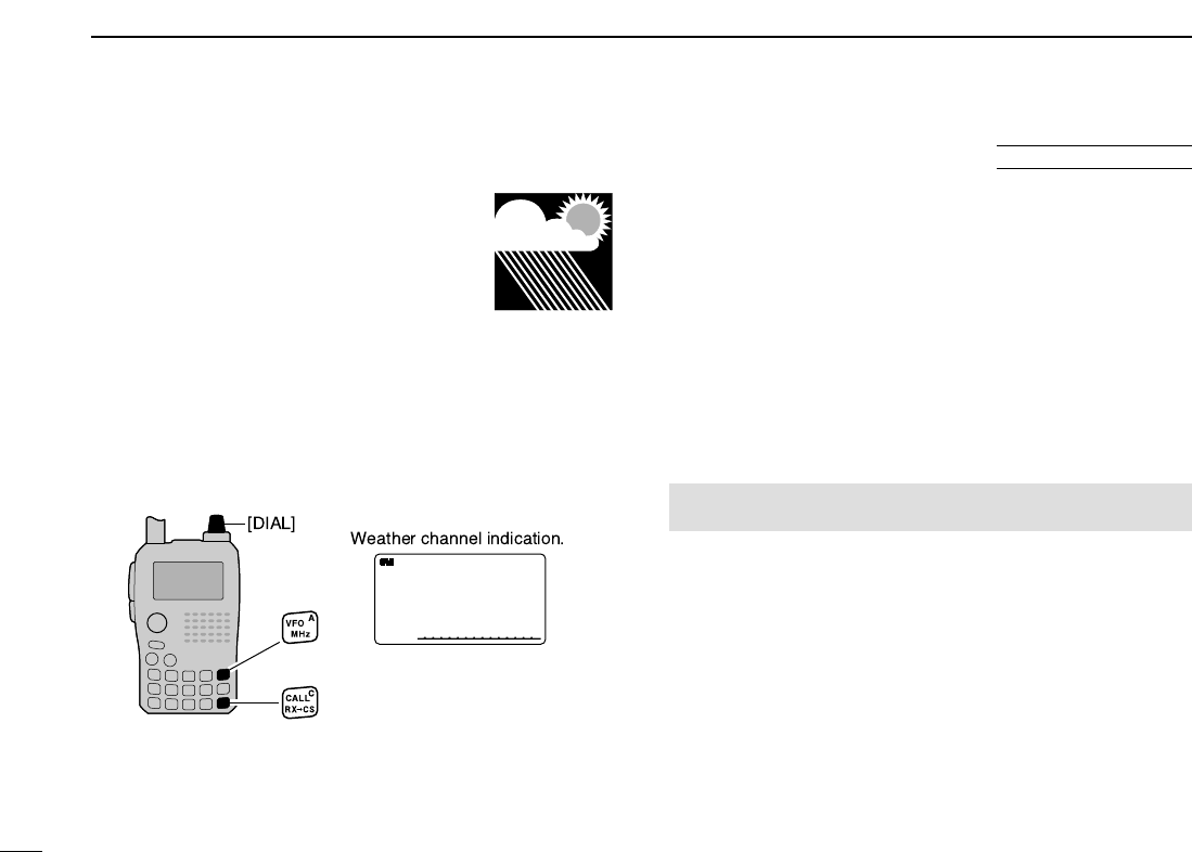
116
12 OTHER FUNCTIONS
■Weather channel operation
There are 10 weather channels for monitor-
ing weather channels from the NOAA (Na-
tional Oceanographic and Atmospheric
Administration) broadcasts.
DDWeather channel selection
qPush [CALL/RX➝CS](C) several times to select weather
channel mode.
•“WX” and the weather channel number appear.
wRotate [DIAL] to select the desired weather channel.
ePush [VFO/MHz] or [MR/S.MW] to return to the previous
frequency or memory channel.
DDWeather alert function
NOAA broadcast stations transmit weather alert tones before
important weather announcements. When the weather alert
function is turned ON, the selected weather channel is moni-
tored every 5 sec. for the announcement. When the alert sig-
nal is detected, the “ALT” and the WX channel are displayed
alternately and sounds a beep tone until the transceiver is op-
erated. The previously selected (used) weather channel is
checked periodically during standby or while scanning.
qSelect the desired weather channel.
wEnter “WEATHER ALERT” in set mode.(p. ??)
eRotate [DIAL]†to select “ON” or “OFF.”
rPush [5/SKIP](ï)to set the weather alert function and
push [MENU/LOCK] to return to the weather channel in-
dication.
tSet the desired stand-by condition.
•Select VFO, memory or call channel.
•Scan or priority watch operation can also be selected.
MENU screen➪SET MODE➪WEATHER ALERT
(Push [MENU/LOCK]) (Rotate [DIAL]†, then push [5/SKIP](ï)†.)
U.S.A. version only
A
WXWX
1
WX
A
WX
1
WX
A
WX
WX
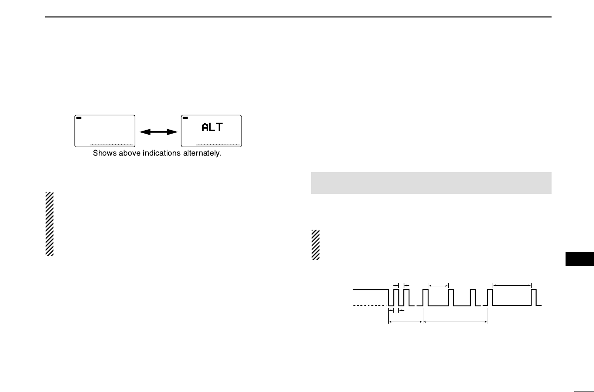
117
12
OTHER FUNCTIONS
1
2
3
4
5
6
7
8
9
10
11
12
13
14
15
16
17
18
19
yWhen the alert is detected, a beep sounds and the follow-
ing indication will be displayed.
uTurn the weather alert function OFF in set mode.
NOTE: While receiving a signal (on a frequency other than
the weather alert ON frequency), the receiving signal or
audio will be interrupted momentarily every 5 sec. (approx.)
in the case that the alert function is turned ON. This symp-
tom is caused by the WX alert function. To cancel these
symptoms, set the weather alert item OFF in set mode.
■Power save
The power save function reduces the current drain to con-
serve battery power.
The power save duty cycle, the ratio of receive circuit on to
receive circuit off while standing by, can be set to automatic
(default), 1 : 1 (150 msec. : 150msec.), 1 : 4 (150 msec. :
600msec.), 1 : 8 (150 msec. : 1200msec.) or OFF in POWER
SAVE set mode. (p. ??)
•“AUTO” selects “1 : 4” duty ratio when receiving no signal for 5 sec.,
then “1 : 8” 60 sec. after that.
When automatic is selected, the power save automatically
turns OFF while operating with an external DC power sup-
ply. (11.0 V DC ± 5 %)
150 msec.
150 msec.
60 sec. 60 sec.
600 msec. 1200 msec.
No signal
5 sec.
Circuit ON
Circuit OFF
∼
∼
∼
∼
MENU screen➪SET MODE➪POWER SAVE
(Push [MENU/LOCK]) (Rotate [DIAL]†, then push [5/SKIP](ï)†.)
A
WX
1
WX
A
WX
1
WXWX
A
WX
WXWX
†[DIAL] ↔[2/SCAN](∫∫)/[8/TS](√√) [5/SKIP](ï)↔[6/M.N](≈≈)

118
12 OTHER FUNCTIONS
■Auto power OFF
The transceiver can be set to automatically turn OFF after a
specified period with a beep when no switch is pushed.
120 min., 90 min., 60 min., 30 min. and OFF can be speci-
fied. The specified period is retained even when the trans-
ceiver is turned OFF by the auto power-off function. To cancel
the function, select “OFF” in the auto power-off item in set
mode.
This can be selected in AP OFF set mode. (p. ??)
■Auto power ON
The transceiver can be set to automatically turn ON after a
specified period. The timer can be selected within 30 min. to
24 hrs. in 30 min. steps.
This can be selected in AP ON set mode. (p. ??)
When operating with battery pack or case and the battery
is exhausted, auto power-on does not function.
■Time-out timer
To prevent accidental prolonged transmission, etc., the trans-
ceiver has a time-out timer. This timer cuts a transmission
OFF after 1, 3, 5 or 10 min. of continuous transmission. This
timer can be cancelled (default).
Approx. 10 sec. before the time-out timer is activated, the
transceiver emits a beep tone as a warning.
This can be selected in TOT set mode. (p. ??)
■PTT lock
To prevent accidental transmission, etc., the transceiver has a
PTT lock function.
This can be selected in PTT LOCK set mode. (p. ??)
MENU screen➪SET MODE➪PTT LOCK
(Push [MENU/LOCK]) (Rotate [DIAL]†, then push [5/SKIP](ï)†.)
MENU screen➪SET MODE➪TOT
(Push [MENU/LOCK]) (Rotate [DIAL]†, then push [5/SKIP](ï)†.)
MENU screen➪SET MODE➪AP ON
(Push [MENU/LOCK]) (Rotate [DIAL]†, then push [5/SKIP](ï)†.)
MENU screen➪SET MODE➪AP OFF
(Push [MENU/LOCK]) (Rotate [DIAL]†, then push [5/SKIP](ï)†.)
†[DIAL] ↔[2/SCAN](∫∫)/[8/TS](√√) [5/SKIP](ï)↔[6/M.N](≈≈)
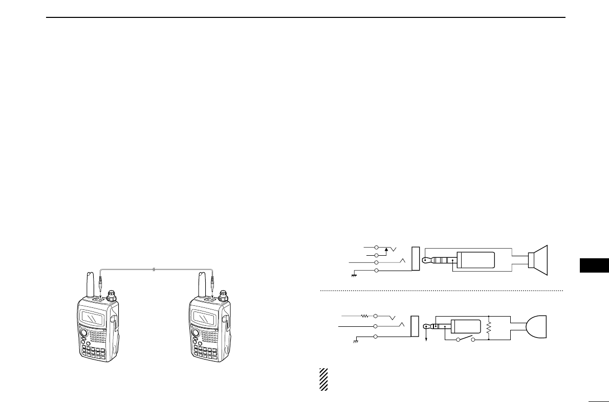
119
12
OTHER FUNCTIONS
1
2
3
4
5
6
7
8
9
10
11
12
13
14
15
16
17
18
19
■Cloning function
The IC-91A/91AD has transceiver-to-transceiver data cloning
capability. This function is useful when you want to copy all
of the programmed contents from one IC-91A/91AD to an-
other.
•An optional OPC-474 CLONING CABLE is required.
qTurn the transceiver’s power OFF, then connect an op-
tional OPC-474 between both [SP] jacks.
wWhile pushing [MR/M.SW] and [MENU/LOCK], push and
hold [PWR] for 1 sec. to enter cloning mode.
•“CLONE” appears.
ePush [PTT] on the “master” transceiver.
•“CL OUT” appears and the signal indicator shows that cloning is
taking place.
rPush and hold [PWR] for 1 sec. to turn power OFF.
The optional RS-91 REMOTE CONTROLL SOFTWARE is also
available to clone/edit contents with a PC (for Microsoft®Win-
dows®98/98SE/ME/2000XP) and using icf format files.
Microsoft®and Windows®are registered trademarks of Microsoft Corporation in
the U.S.A. and other countries.
■[MIC/SP] jacks
To connect external equipment such as speaker, microphone,
TNC, etc. refer to the diagram below.
The center terminal of [MIC] outputs 3.0 V DC via 330 Ω
registor.
External
speaker
the [SP] jack
SP
SP
GND
ø3.5 mm
plug
the [MIC] jack
33 kΩ
330 Ω
MIC
MIC
GND
External
microphone
ø2.5 mm
plug
PTT
3.0 V (See below)
Impedance 8 Ω
Impedance 2 kΩ
MIC
3.0 V
MIC GND
INTERNAL SP
SP (AF OUT)
CLONE
SP GND
OPC-474
to the [SP] jack to the [SP] jack
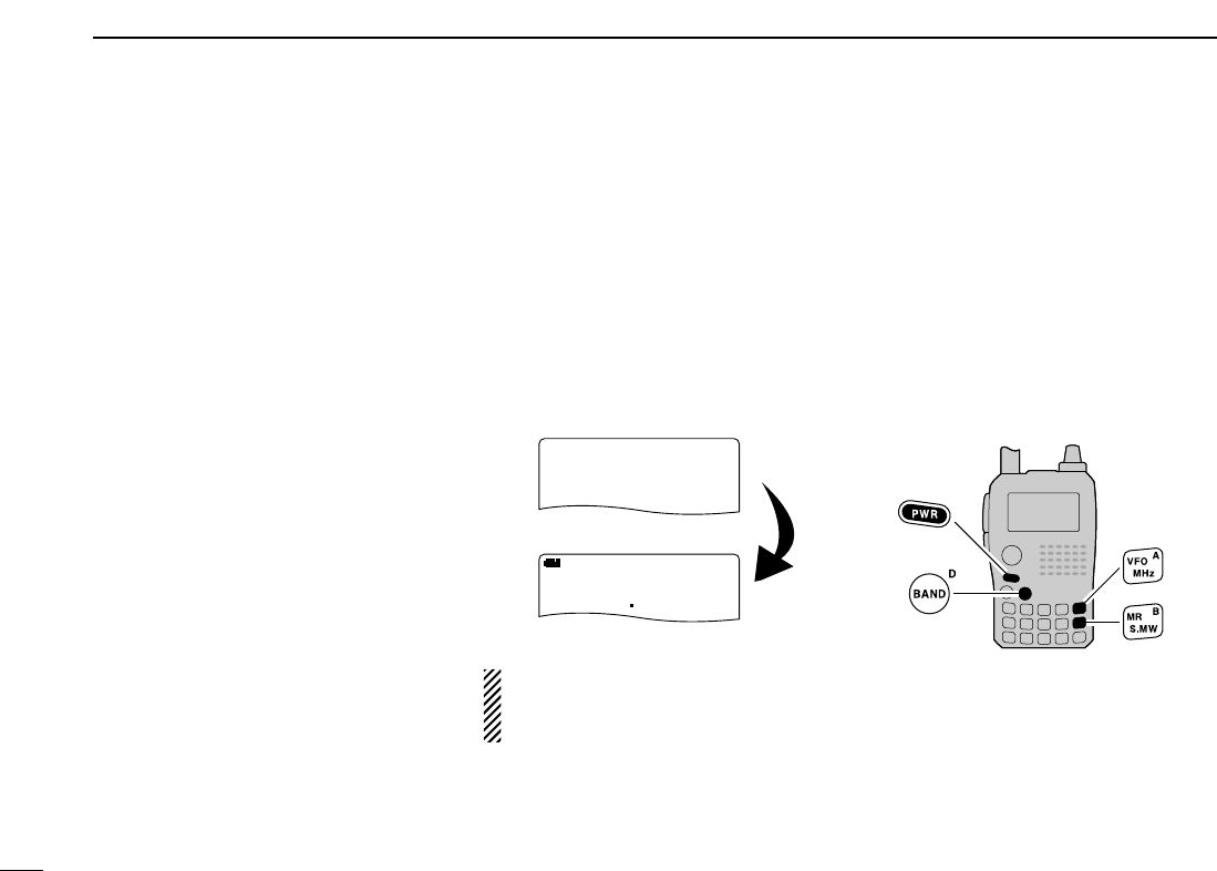
120
12 OTHER FUNCTIONS
■Resetting
The function display may occasionally
display erroneous information (e.g.
when first applying power). This may be
caused externally by static electricity or
by other factors.
If this problem occurs, turn power OFF.
After waiting a few seconds, turn power
ON again. If the problem persists, per-
form either or both procedures below.
•All reset
Reset the CPU before operating the
transceiver for the first time, or when
the internal CPU malfunctions to clear
and return all programmed contents to
their default settings.
•Partial reset
If you want to initialize the operating
conditions (VFO frequency, VFO set-
tings, set mode contents) without clear-
ing the memory contents, a partial
resetting function is available for the
transceiver.
DAll reset
qPush and hold [PWR] for 2 sec. to
turn power OFF.
wWhile pushing and holding
[VFO/MHz], [MR/S.MW] and
[BAND], then turn power ON to
reset the CPU.
•“ALL RESET” appears when resetting
the CPU (See the below illlustration).
CAUTION: Resetting the CPU re-
turns all programmed contents to
their default settings.
DPartial reset
qPush and hold [PWR] for 2 sec. to
turn power OFF.
wWhile pushing and holding [VFO/MHz],
then turn power ON to partially reset
the transceiver.
[NOTE]: No message appears on the
display after the partially resetting has
done.
ALL RESET
PRIO WX EMR
DTCS
FM
B
A
146010
+DUP
25
PRIO WX EMR
DTCS
FM
B
A
145000
+DUP
25
PRIO WX EMR
DTCS
FM
B
A
438550
+DUP
25
ALL RESETALL RESET
PRIOPRIO WXWX EMREMR
DTCSDTCS
FMFM
B
A
146010
+DUP+DUP
25
PRIO WX EMR
DTCS
FM
B
A
145000
+DUP
25
PRIO WX EMR
DTCS
FM
B
A
438550
+DUP
25
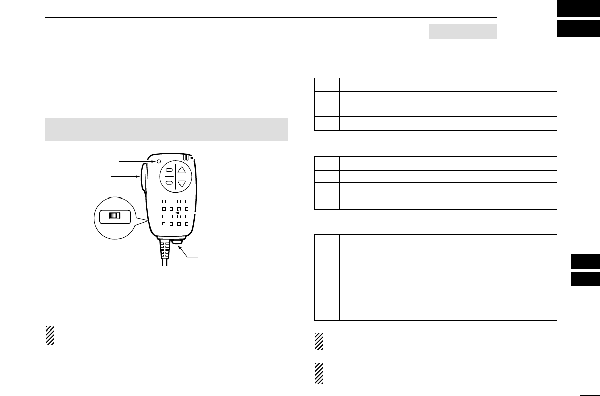
121
13
HM-75A REMOTE CONTROL MICROPHONE
1
2
3
4
5
6
7
8
9
10
11
12
13
14
15
16
17
18
19
The optional HM-75A allows you to remotely select operating
frequencies, memory channels, etc.
Remote control functions can be selected from 3 settings.
These can be selected in MIC SIMPLE set mode. (p. ??)
The HM-75A has a lock switch on the backside to prevent ac-
cidental frequency changes, etc.
Be sure to turn power OFF when plugging the HM-75A to
the [MIC/SP] jacks.
•NORM-1: (default)
•NORM-2:
•SIMPLE:
VFO mode cannot be selected via the microphone when
SIMPLE mode is selected.
SIMPLE mode can select only 3 channels and is useful for
group operations during touring, etc.
A
OFF ON
LOCK
B
PTT switch
Transmit LED
Earphone jack
Microphone
Speaker
MENU screen➪SET MODE➪MIC SIMPLE
(Push [MENU/LOCK]) (Rotate [DIAL]†, then push [5/SKIP](ï)†.)
[A] Selects band.
[B] Toggles VFO mode and memory mode.
[Y] Frequency or memory channel “UP”.
[Z] Frequency or memory channel “DOWN”.
[A] Toggles the monitor function.
[B] Toggles VFO mode and memory mode.
[Y] Frequency or memory channel “UP”.
[Z] Frequency or memory channel “DOWN”.
[A] Toggles the monitor function.
[B] Selects call channel C0.
[Y]• Selects memory channel 000 in memory mode.
• Volume “UP” while operating the monitor function.
• Selects memory channel 001 in memory mode.
[Z]• Volume “DOWN” while operating the monitor func-
tion.
OPTIONAL

PROBLEM
No power comes ON.
No sound comes from the
speaker.
Transmitting is impossible.
No contact possible with
another station.
Frequency can not be set.
Program scan function
can not start.
Memory scan function can
not start.
The displayed frequency is
not properly.
Can not charge the battery
with BC-139 (LED blinks
orange).
122
TROUBLESHOOTING
14
If your transceiver seems to be malfunctioning, please check the following points before sending it to a service center.
POSSIBLE CAUSE
• The batteries are exhausted.
• The battery polarity is reversed.
• Volume level is too low.
• Different tone is selected with tone/DTCS
squelch.
• The batteries are exhausted.
• A frequency outside of the 144/440 MHz
amateur bands is set.
• Different tone is selected with tone/DTCs
squelch.
• The lock function is activated.
• Memory or call channel is selected.
• Memory mode is selected.
• Same frequencies are programmed both
“✱A” and “✱B” of PROGRAM-CH.
• VFO mode is selected.
• The programmed memory channel is only
one.
• The CPU is malfunctioned.
• Depends on external factors.
• Turn the transceiver’s power is ON.
SOLUTION
• Replace the batteries or chage the battery pack.
• Check the battery polarity.
• Rotate [VOL] to suitable level.
• Check the tone using tone/DTCS scan.
• Replace the batteries or charge the battery pack.
• Reset the frequency within 144/440 MHz amateur
bands.
• Check the tone using tone scan.
• Push [MENU/LOCK] for 1 sec. to cancel the function.
• Push [VFO/MHz] to set VFO mode.
• Push [VFO/MHz] to set VFO mode.
• Programming different frequencies to “✱A” and “✱B” re-
spectively.
• Push [MR/S.MW] to set memory mode.
• Program more than 2 memory channels.
• Reset the transdeiver.
• Re-attach the battery pack or battery case.
• Turn the transceiver’s power OFF, or insert the battery
pack only into BC-139 to chage it.
REF.
pgs. ?, ??
p. ??
p. ??
p. ??
pgs. ??, ??
p. ??
p. ??
p. ??
p. ??
p. ??
p. ??
p. ??
p. ??
p. ??
p. ??
p. ??

123
15
SPECIFICATIONS
1
2
3
4
5
6
7
8
9
10
11
12
13
14
15
16
17
18
19
DGeneral
•Frequency coverage : (unit: MHz)
*1Guaranteed 440–450 MHz only, *2Guaranteed 144–148 MHz only
*3Guaranteed 430–440 MHz only
•Mode : FM, AM (Rx only), WFM (Rx only)
•No. of memory channels : 1300 (incl. 100 scan edges)
•No. of call channels : 4 channels
•Usable temp. range : –20°C to +60°C; –4°F to +140°F
•Tuning steps : 5*4, 6.25*4, 8.33*4, 9*4, 10, 12.5, 15,
20, 25, 30, 50, 100, 125 and 200 kHz
•Frequency stability : ±2.5 ppm
(–20°C to +60°C;–4°F to +140°F)
•Power supply : 7.4 V DC (Icom’s battery pack only;
10.0–16.0 V DC acceptable)
•Digital transmission speed : 4.8 kbps*5
•Voice coding speed : 2.4 kbps*5
•Current drain (at 7.4 V DC) :
Tx High 144 MHz 2.1 A typical
440 MHz 2.2 A typical
Tx Low 144, 440 MHz 0.8 A (approx.)
Rx max. power 340 mA typical(dualwatch FM/DV*5)
standby 170 mA typical(dualwatch FM/DV*5)
•Antenna connector : SMA (50 Ω)
•Dimensions : 58.4(W)×103(H)×34.2(D) mm;
(projections not included) 29⁄32(W)×41⁄16(H)×111 ⁄32(D) in
•Weight (approx.) : 300 g; 10.6 oz
(with antenna and BP-217)
•
Ext. data connector
: 3-conductor 2.5(d) mm; (1⁄10˝)
DTransmitter
•Modulation system :
FM Variable reactance frequency
modulation
DV (Digital)*5GMSK reactance frequency
modulation
•Output power (at 7.4 V DC) :
144 MHz High 5.0 W, Low 0.5 W (approx.)
440 MHz High 5.0 W, Low 0.5 W (approx.)
•Max. frequency deviation : ±5.0 kHz (FM wide: approx.)
±2.5 kHz (FM narrow: approx.)
•Spurious emissions : Less than –60 dB
•
Ext. Microphone connector
: 3-conductor 2.5(d) mm; (1⁄10˝)2 kΩ
*4Selectable depending on the operating frequency band.
*5Available for IC-91AD or when UT-121 is installed into IC-91A.
A bandVersion
U.S.A
Taiwan
Korea
Australia
Expand
TX: 144–148, 420–450*1
RX:0.500–824*1,*2
849–869,*1,*2
894–999.990*1,*2
TX: 144–146, 430–432
RX:144–146, 430–432
TX: 144–146, 430–440
RX:144–146, 430–440
TX: 144–148, 420–450*1
RX:0.495–999.990*1,*2
TX: 136–173.995*2
400–478.995*3
RX:0.495–999.990*2,*3
TX: 144–148, 420–450*1
RX:118–173.995*1,*2
350–469.995,*1,*2
TX: 144–146, 430–432
RX:144–146, 430–432
TX: 144–146, 430–440
RX:144–146, 430–440
TX: 144–148, 420–450*1
RX:118–173.995*1,*2
350–469.995,*1,*2
TX: 136–173.995*2
400–478.995*3
RX:118–173.995*2
350–469.995*3
B band

124
15 SPECIFICATIONS
DReceiver
•Receive system : Double-conversion superheterodyne (FM/AM)
Triple-conversion superheterodyne (WFM)
•Intermediate frequencies :
1st (A band) 61.65 MHz/59.25 MHz (WFM)
1st (B band) 46.35 MHz
2nd 450 kHz/13.35 MHz (WFM)
3rd 1.95 MHz (WFM)
•Sensitivity(except spurious points) :
AM (1 kHz/30% MOD.; 10 dB S/N)
0.495–4.995 MHz 1.3 µV typ.
5.000–29.995 MHz 0.56 µV typ.
118.000–137.000 MHz 0.5 µV typ.
222.000–246.995 MHz 0.79 µV typ.
247.000–329.995 MHz 1 µV typ.
FM (1 kHz/3.5 kHz Dev.; 12 dB SINAD)
VHF (Amateur band only) 0.14 µV typ.
UHF (Amateur band only) 0.16 µV typ.
1.625–29.995 MHz 0.4 µV typ.
30.000–117.995 MHz 0.25 µV typ.
118.000–173.995 MHz 0.18 µV typ.
174.000–349.995 MHz 0.32 µV typ.
350.000–469.995 MHz 0.22 µV typ.
470.000–599.995 MHz 0.32 µV typ.
600.000–999.990 MHz 0.56 µV typ.
WFM (1 kHz/52.5 kHz Dev.; 12 dB SINAD)
76.000–108.000 MHz 1 µV typ.
175.000–221.995 MHz 1.8 µV typ.
470.000–770.000 MHz 2.5 µV typ.
DV(digital/PN9 4.8kpps; BER 1%)*5
VHF (Amateur band only) 0.22 µV typ.
UHF (Amateur band only) 0.22 µV typ.
•Selectivity :
FM (Wide), AM More than 50 dB
FM (Narrow), DV*5More than 45 dB
WFM More than 300 kHz/–3 dB
Less than 700 kHz/–20 dB
•Spurious and image rejection ratio:
VHF More than 60dB
UHF More than 50dB
(Intermediate freq.; More than 60dB)
•Audio output power : More than 20 mW at 10% distortion
(at 7.4 V DC) with an 8 Ωload
•
Ext. speaker connector
: 4-conductor 3.5(d) mm; (1⁄8˝)8Ω
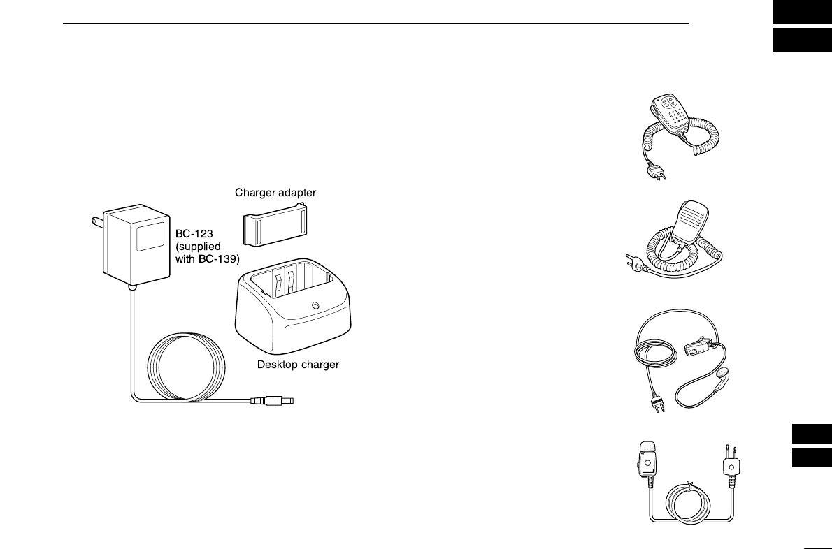
125
16
OPTIONS
1
2
3
4
5
6
7
8
9
10
11
12
13
14
15
16
17
18
19
UT-121
DIGITAL UNIT
Available to operate DV mode for IC-91A.
BC-139
DESKTOP CHARGER
Rapidly charges BP-217 Li-ion battery pack in 2 hrs. and 30
min.
BP-216
BATTERY CASE
Battery case for R6 (AA) ×2 alkaline batteries.
BP-217
LI
-
ION BATTERY PACK
7.4 V/1300 mAh Lithium Ion battery pack. Approx. 6 hrs. and
20 min. operating time in with high power, Tx : Rx : Standby =
1:1:8.
HM-75A
REMOTE CONTROL MI
-
CROPHONE
Allows you to remotely select
operating channels, etc.
HM-131
SPEAKER
-
MICRO
-
PHONE
For operation while conve-
niently hanging the transceiver
from your belt, etc.
HM-128/HM-153
EARPHONE
-
MICROPHONE
Ideal for hands-free operation
by clipping the microphone
with the PTT switch to your
lapel or breast pocket.
HM-75A
HM-131
HM-128
HM-153
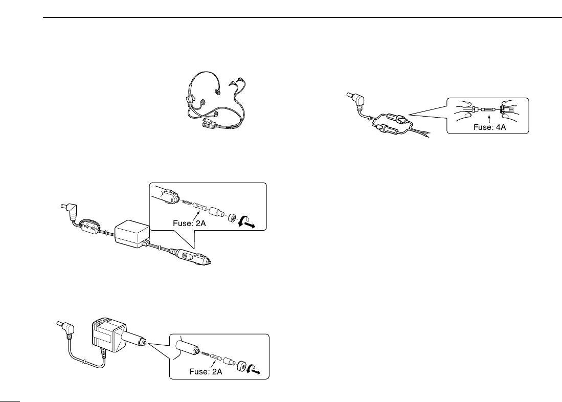
126
16 OPTIONS
HS-85
HEADSET WITH VOX
/
PTT
UNIT
Hands-free headset with VOX
control box.
CP-19R
CIGARETTE LIGHTER CABLE WITH NOISE FILTER
Used for operation and charging a battery pack connected to
the transceiver via a DC power source. (11.5–16 V DC)
CP-12L
CIGARETTE LIGHTER CABLE WITH NOISE FILTER
Allows you to charge the transceiver using supplied BC-139
BATTERY CHARGER
.
CP-254L
DC POWER CABLE
For operation and charging via an external power supply.
RS-91
REMOTE CONTROL SOFTWARE
+ OPC-1529
DATA COMMUNICATION CABLE
Allows you to operate the connected transceiver. In addition,
transfer data from memories, etc. and quickly and easily edit
and store data via a PC for Microsoft®Windows®
98/98SE/ME/2000/XP. An RS-232C (COM) port is required.
OPC-474
CLONING CABLE
Used for handheld-to-handheld cloning.
SP-13
EARPHONE
Provides clear receive audio in noisy environments.
LC-163
CARRYING CASE
Helps protect the transceiver from scratches, etc.
AD-92SMA
CARRYING CASE
Helps protect the transceiver from scratches, etc.
CP-254L
CP-12L
CP-19R
Microsoft®and Windows®are registered trademarks of Microsoft Cor-
poration in the U.S.A. and other countries.
HM-131

127
11
CHAPTER CONTINUED
1
2
3
4
5
6
7
8
9
10
11
12
13
14
15
16
17
18
19

1-1-32 Kamiminami, Hirano-ku, Osaka 547-0003, Japan
A-6463X-1EX
Printed in Japan
©2006 Icom Inc.