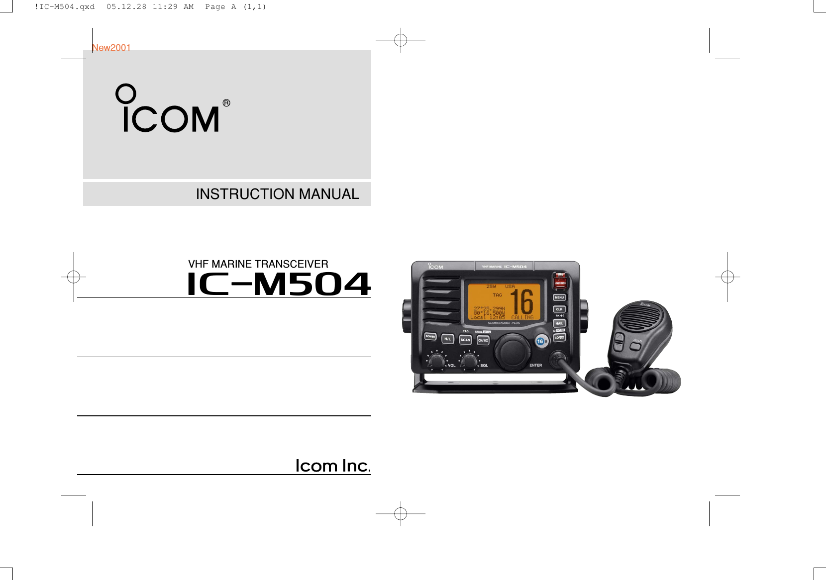
ICOM orporated 291400 VHF-FM Marine Transceiver User Manual Manual
ICOM Incorporated VHF-FM Marine Transceiver Manual
UserManual.wiki
>
ICOM orporated
>
291400 User Manual
Manual
Navigation menu
Upload a User Manual
Namespaces
Wiki Guide
HTML
PDF
Info
Views
User Manual
Discussion / Help
Navigation
![iiIN CASE OF EMERGENCYIf your vessel requires assistance, contact other vessels andthe Coast Guard by sending a Distress call on Channel 16.Or, transmit your Distress call using digital selective callingon Channel 70.NOTEA WARNING STICKER is supplied with the transceiver.To comply with FCC regulations, this sticker must be affixed insuch a location as to be readily seen from the operating con-trols of the radio as in the diagram below. Make sure the cho-sen location is clean and dry before applying the sticker.EXAMPLEUSING DIGITAL SELECTIVE CALLING (Ch 70)DISTRESS CALL PROCEDURE1. While lifting up the key cover, push and hold[DISTRESS] for 5 sec. until you hear 5 short beepschange to one long beep.2. Wait for an acknowledgment on Channel 70 from a coaststation.• After the acknowledgement is received, Channel 16 is auto-matically selected.3. Push and hold [PTT], then transmit the appropriateinformation as listed above.USING CHANNEL 16DISTRESS CALL PROCEDURE1. “MAYDAY MAYDAY MAYDAY.”2. “THIS IS ...............” (name of vessel).3. Say your call sign or other indication of the vessel (AND9-digit DSC ID if you have one).4. “LOCATED AT ...............” (your position).5. State the nature of the distress and assistance required.6. Give any other information which might facilitate therescue.New2001!IC-M504.qxd 05.12.28 11:29 AM Page ii (1,1)](https://usermanual.wiki/ICOM-orporated/291400/User-Guide-634763-Page-3.png)
![2PANEL DESCRIPTIONNew20012■Front panelqDISTRESS KEY [DISTRESS]Push for 5 sec. to transmit a Distress call. (p. 23)wDSC MENU KEY [MENU]Push to toggle the DSC menu appear or disappear. (p. 15)eCLEAR KEY [CLR]Push to cancel the entered function, exit Set mode. (p. 55)rHAIL/RX SPEAKER KEY [HAIL•RX ]➥Push to turn the hailer mode ON or OFF. (p. 52)➥Push and hold for 1 sec. to turn the RX Speaker modeON or OFF. (p. 51)➥While pushing and holding [H/L], push to turn the autofoghorn function ON. (p. 54)tATTENUATOR/INTERCOM KEY [LO/DX•IC•SCRM]➥Push to turn the Attenuator function ON or OFF. (p. 8)•“LLOOCC” appears when the Attenuator function is turned ON.➥Push and hold for 1 sec. to activate an optional Inter-com function. (p. 50)➥Push and hold to calls the optional command micro-phone while in Intercom mode. (p. 50)➥While pushing and holding [H/L], push to turn the voicescrambler function ON or OFF. (p. 11)yCHANNEL 16/CALL CHANNEL KEY [16•9]➥Push to select Channel 16. (p. 6)➥Push and hold for 1 sec. to select Call channel. (p. 6)•“CCAALLLL” appears when Call channel is selected.➥Push and hold for 3 sec. to enter Call channel program-ming condition when Call channel is selected. (p. 9)➥While pushing and holding [H/L], push to enter thechannel comment programming condition. (p. 10)➥Advance the cursor while in the channel comment pro-gramming condition. (p. 10)➥While turning power ON, push to enter Set mode. (p. 55)Function display (p. 4)Speakerqertywuio!0!1!2!3!IC-M504.qxd 05.12.28 11:29 AM Page 2 (1,1)](https://usermanual.wiki/ICOM-orporated/291400/User-Guide-634763-Page-8.png)
![32PANEL DESCRIPTIONNew2001uCHANNEL SELECTOR [DIAL•ENTER]➥Rotate to select the operating channels, Set mode set-tings, etc. (pgs. 6, 7, 55)➥While pushing and holding [H/L], rotate to adjust thebrightness of the LCD and key backlight. (p. 10)➥Push to enter the input channel comment, selecteditem, etc. (pgs. 10, 55)➥Rotate to check TAG channels, changes scanning di-rection or resumes the scan manually during scan.(p. 13)➥While pushing and holding [PA•RX ], rotate to adjustthe audio level in RX Speaker mode. (p. 51)iCHANNEL/WEATHER CHANNEL KEY[CH/WX•DUAL•U/I/C]➥Selects and toggles the regular channel and Weatherchannel when pushed momentarily. (p. 7)➥Push and hold for 1 sec. to start Dualwatch or Tri-watch.(p. 14)➥Push to stop Dualwatch or Tri-watch when either is acti-vated. (p. 14)➥Move the cursor backward while in the channel com-ment programming condition. (p. 10)➥While pushing and holding [H/L], push to select one ofthree channel groups in sequence. (p. 7)• U.S.A., International and Canadian channels are available.oSQUELCH CONTROL [SQL]Rotate to set the squelch threshold level. (p. 8)!0 SCAN KEY [SCAN•TAG] (p. 13)➥Push to start and stop Normal or Priority scan.➥Push and hold for 1 sec. to set or clear the displayedchannel as a TAG (scanned) channel.➥While pushing and holding [H/L], push for 3 sec. toclear or set all TAG channels in the selected channelgroup.!1 VOLUME CONTROL [VOL] (p. 8)Rotate to adjust the audio level.!2 TRANSMIT POWER KEY [H/L]➥Push to toggle the power high or low. (p. 8)• Some channels are set to low power only.➥While pushing this key, some keys perform secondaryfunctions.!3 POWER KEY [POWER] (p. 8)➥Push to turn power ON.➥Push and hold for 1 sec. to turn power OFF.2!IC-M504.qxd 05.12.28 11:29 AM Page 3 (1,1)](https://usermanual.wiki/ICOM-orporated/291400/User-Guide-634763-Page-9.png)
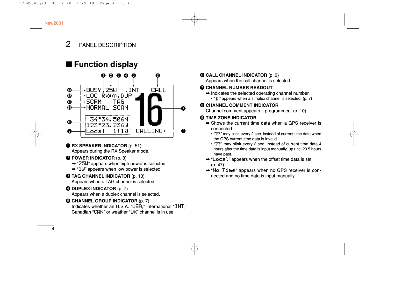
![52PANEL DESCRIPTIONNew20012!0 POSITION INDICATOR➥Shows the GPS position data.•“????” may blink every 2 sec. instead of position data when theGPS position data is invalid. In such a case, the last positiondata is held for up to 23.5 hours.•“????” may blink every 2 sec. instead of position data 4 hoursafter the position data is input manually, up until 23.5 hourshave past.➥“NNoo PPoossiittiioonn” appears when no GPS receiver isconnected and no position data is input manually.!1 SCAN INDICATOR➥“PPRRII--SSCCAANN 1166” appears during Priority scan; “NNOORRMMAALL SSCCAANN” appears during Normal scan. (p. 13)➥“DDUUAALL 1166” appears during Dualwatch; “TTRRII 1166” ap-pears during Tri-watch. (p. 14)!2 SCRAMBLER INDICATOR (p. 11)Appears when the voice scrambler function is activated.(only when the optional scrambler unit is installed.)!3 LOCAL INDICATOR (p. 8)Appears when the Attenuator function is turned ON.!4 BUSY/TRANSMIT INDICATOR (p. 8)➥“BBUUSSYY” appears when receiving a signal or when thesquelch opens.➥“TTXX” appears while transmitting.■MicrophoneqPTT SWITCH [PTT]Push and hold to transmit; release to receive. (p. 8)wCHANNEL UP/DOWN KEYS [YY]/[ZZ]➥Push either key to change the operating memory chan-nel, Set mode settings, etc. (pgs. 6, 7, 55)➥Checks TAG channels, changes scanning direction orresumes the scan manually during scan. (p. 13)eTRANSMIT POWER KEY [HI/LO]➥Toggles power high and low when pushed. (p. 8)• Some channels are set to low power only.➥While pushing and holding [HI/LO], turn power ON totoggle the Microphone Lock function ON and OFF.(p. 10)Microphonewqe!IC-M504.qxd 05.12.28 11:29 AM Page 5 (1,1)](https://usermanual.wiki/ICOM-orporated/291400/User-Guide-634763-Page-11.png)
![6BASIC OPERATIONNew20013■Channel selectionïïChannel 16Channel 16 is the distress and safety channel. It is used forestablishing initial contact with another station and for emer-gency communications. Channel 16 is monitored during bothDualwatch and Tri-watch. While standing by, you must moni-tor Channel 16.➥Push [16•9] momentarily to select Channel 16.➥Push [CH/WX•DUAL•U/I/C] to return to the condition beforeselecting Channel 16, or rotate [DIAL] to select an operatingchannel.ïïChannel 9 (Call channel)Each regular channel group has a separate leisure-use callchannel. The call channel is monitored during Tri-watch. Thecall channels can be programmed (p. 9) and are used to storeyour most often used channel in each channel group for quickrecall.➥Push [16•9] for 1 sec. to select the call channel of the se-lected channel group.•“CCAALLLL” and call channel number appear.• Each channel group may have an independent call channel afterprogramming a call channel. (p. 9)➥Push [CH/WX•DUAL•U/I/C] to return to the condition be-fore selecting call channel, or rotate [DIAL] to select an op-erating channel.25W25W INTINT CALLCALLTAGTAG3434°34.506N34.506N123123°23.236W23.236WUTCUTC 1212:00:00 CALLINGCALLINGPushfor 1 sec.25W INTTAG34°34.506N123°23.236WUTC 12:00 CALLINGPush!IC-M504.qxd 05.12.28 11:29 AM Page 6 (1,1)](https://usermanual.wiki/ICOM-orporated/291400/User-Guide-634763-Page-12.png)
![73BASIC OPERATIONNew20013ïïU.S.A., international and Canadian channelsThe IC-M504 is pre-programmed with 57 U.S.A., 57 interna-tional and 61 Canadian channels. These channel groups maybe specified for the operating area.qPush [CH/WX•DUAL•U/I/C] to select a regular channel.• If a weather channel appears, push [CH/WX•DUAL•U/I/C] again.wWhile pushing and holding [H/L], push [CH/WX•DUAL•U/I/C] to change the channel group, if necessary.• U.S.A., International and Canadian channel groups can be se-lected in sequence.eRotate [DIAL] to select a channel.•“DDUUPP” appears for duplex channels.• “ ” appears when a simplex channel is selected.ïïWeather channelsThe IC-M504 has 10 weather channels. These are used formonitoring broadcasts from NOAA (National Oceanographicand Atmospheric Administration.)The transceiver can detect a weather alert tone on the se-lected weather channel while receiving the channel, duringstandby on a regular channel or while scanning. (p. 56)qPush [CH/WX•DUAL•U/I/C] once or twice to select aweather channel.•“WWXX” appears when a weather channel is selected.• “WWXX AALLEERRTT” appears when the Weather Alert function is inuse. (p. 56)wRotate [DIAL] to select a channel.WXWX ALERTALERT3434°34.506N34.506N123123°23.236W23.236WUTCUTC 1212:00:00163163.275MHz.275MHzWXWX3434°34.506N34.506N123123°23.236W23.236WUTCUTC 1212:00:00163163.275MHz.275MHzPush once or twiceWhen weather alert is OFF. When weather alert is ON.25W25W USAUSA3434°34.506N34.506N123123°23.236W23.236WUTCUTC 1212:00:00 PORTPORT OPROPR25W25W INTINTDUPDUP3434°34.506N34.506N123123°23.236W23.236WUTCUTC 1212:00:00 TELEPHONETELEPHONE25W25W CANCAN3434°34.506N34.506N123123°23.236W23.236WUTCUTC 1212:00:00 CCGCCGPush +!IC-M504.qxd 05.12.28 11:29 AM Page 7 (1,1)](https://usermanual.wiki/ICOM-orporated/291400/User-Guide-634763-Page-13.png)
![83BASIC OPERATIONNew2001■Receiving and transmittingCAUTION: Transmitting without an antenna may dam-age the transceiver.qPush [POWER] to turn power ON.wSet the audio and squelch levels.➥Rotate [SQL] fully counterclockwise in advance.➥Rotate [VOL] to adjust the audio output level.➥Rotate [SQL] clockwise until the noise disappears.eWhile pushing and holding [H/L], push [CH/WX•DUAL•U/I/C] to change the channel group. (p. 7)rRotate [DIAL] to select the desired channel. (pgs. 6, 7)• When receiving a signal, “BBUUSSYY” appears and audio is emittedfrom the speaker.• Further adjustment of [VOL] may be necessary.tPush [LO/DX•IC•SCRM] to turn the receive Attenuatorfunction ON or OFF, if necessary.•“LLOOCC” appears when the receive Attenuator function is in use.yPush [H/L] to select the output power if necessary.•“2255WW” or “11WW” appears when high or low power is selected, re-spectively.• Choose low power for short range communications, choose highpower for longer distance communications.• Some channels are for low power only.uPush and hold [PTT] to transmit, then speak into the mi-crophone.•“TTXX” appears.• Channel 70 cannot be used for transmission other than DSC.iRelease [PTT] to receive.Simplex channels, 3, 21, 23, 61, 64, 81, 82 and 83 CAN-NOT be lawfully used by the general public in U.S.A. wa-ters.IMPORTANT: To maximize the readability of your trans-mitted signal, pause a few sec. after pushing [PTT], holdthe microphone 2 to 4 inches (5 to 10 cm) from your mouthand speak into the microphone at a normal voice level.tMicrophoneqyrewwiurey!IC-M504.qxd 05.12.28 11:29 AM Page 8 (1,1)](https://usermanual.wiki/ICOM-orporated/291400/User-Guide-634763-Page-14.png)
![93BASIC OPERATIONNew20013■Call channel programmingCall channel is used to select Channel 9 (default), however,you can program the call channel with your most often-usedchannels in each channel group for quick recall.qWhile pushing and holding[H/L], push [CH/WX•DUAL•U/I/C] one or more times toselect the desired channelgroup (U.S.A., Internationalor Canada) to be pro-grammed.wPush [16•9] for 1 sec. to se-lect the call channel of theselected channel group.•“CCAALLLL” and call channelnumber appear.ePush [16•9] again for 3 sec.(until a long beep changesto 2 short beeps) to enterthe call channel program-ming condition.• Channel number starts blink-ing.rRotate [DIAL] to select thedesired channel.tPush [16•9] to program thedisplayed channel as thecall channel.• Push [CLR] to cancel.• The channel number stopsblinking.25W25W INTINTDUPDUP3434°34.506N34.506N123123°23.236W23.236WUTCUTC 1212:00:00 INTLINTL25W25W INTINT CALLCALLTAGTAG3434°34.506N34.506N123123°23.236W23.236WUTCUTC 1212:00:00 CALLINGCALLING25W25W INTINT CALLCALLTAGTAG3434°34.506N34.506N123123°23.236W23.236WUTCUTC 1212:00:00 CALLINGCALLING25W25W INTINT CALLCALLDUDUP3434°34.506N34.506N123123°23.236W23.236WUTCUTC 1212:00:00 INTLINTL25W25W INTINT CALLCALLDUPDUP3434°34.506N34.506N123123°23.236W23.236WUTCUTC 1212:00:00 INTLINTL!IC-M504.qxd 05.12.28 11:29 AM Page 9 (1,1)](https://usermanual.wiki/ICOM-orporated/291400/User-Guide-634763-Page-15.png)
![103BASIC OPERATIONNew2001■Channel commentsMemory channels can be labelled with alphanumeric com-ments of up to 10 characters each for easy channel recogni-tion.Capital letters, small letters, 0 to 9, some symbols (– . /) andspace can be used. qSelect the desired channel.• Cancel Dualwatch, Tri-watch or Scan in advance.wWhile pushing and holding[H/L], push [16•9] to editthe channel comment.• A cursor and the first char-acter start blinking alter-nately.eSelect the desired charac-ter by rotating [DIAL].• Push [16•9] or [CH/WX•DUAL•U/I/C] to move the cursor forwardor backward, respectively.rRepeat step eto input all characters.tPush [DIAL•ENTER] to input and set the comment.• Push [CLR] to cancel.• The cursor and the character stop blinking.yRepeat steps qto tto program other channel com-ments, if desired.■Microphone Lock functionThe Microphone Lock function electrically locks [Y]/[Z]and[HI/LO] keys on the supplied microphone. This prevents ac-cidental channel changes and function access.➥While pushing and holding [HI/LO] on the microphone, turnpower ON to toggle the Lock function ON and OFF.■Display backlightThe function display and keys can be backlit for better visibil-ity under low light conditions.➥While pushing and holding [H/L], rotate [DIAL] to adjustthe brightness of the LCD and key backlight.• The backlight is adjustable in 7 levels and OFF.[HI/LO][Y]/[Z]25W25W INTINT3434°34.506N34.506N123123°23.236W23.236WUTCUTC 1212:00:00PLEASURE__PLEASURE__!IC-M504.qxd 05.12.28 11:29 AM Page 10 (1,1)](https://usermanual.wiki/ICOM-orporated/291400/User-Guide-634763-Page-16.png)
![113BASIC OPERATIONNew20013■Optional voice scrambler operationDDActivating the scramblerThe optional voice scrambler provides private communica-tions. In order to receive or send scrambled transmissionsyou must first activate the scrambler function. To activate thefunction, an optional scrambler unit is necessary. See pgs.57, 62 for setting the scrambler unit. Ask your dealer for de-tails.The scrambler function automatically turns OFF whenChannel 16 or 70 is selected.qRotate [DIAL] to select an operating channel other thanChannel 16 and 70.wWhile pushing and holding [H/L], push [LO/DX•IC•SCRM]to turn the optional scrambler function ON.•“SSCCRRMM” appears.eTo turn the scrambler function OFF, repeat step w.•“SSCCRRMM” disappears.DDProgramming scrambler codesThere are 32 codes (1 to 32) or 128 codes (0 to 127)* avail-able for programming when the optional scrambler unit is in-stalled. In order to understand one another, all transceiversin your group must have the same scramble code. This func-tion may not be available depending on dealer setting.*Depends on the installed scrambler unit.qTurn power OFF.wWhile pushing [16•9], turn power ON to enter set mode.eAfter the display appears, release [16•9].rRotate [DIAL] to select the “SSccrraammbblleerr CCooddee,” push[DIAL•ENTER].tRotate [DIAL] to select the desired scrambler code.yPush [DIAL•ENTER] to set and exit the scrambler codeitem.uPush [CLR], or rotate [DIAL] to select “EExxiitt,” push[DIAL•ENTER] to exit set mode.--Set Mode--Scrambler Code˘54321<ENT˘OK>--Set Mode--Dual/TriBeepContrastFoghorn FrequencyRadio PowerScrambler Type˘Scrambler Code--Set Mode--Mode--˘Scan TypeScan TimerWX AlertAlertDual/TriBeepContrastFoghorn FrequencyFrequency+to enter set mode.Pushto select code,then push.Rotateto select item,then push.RotateSelectSelect[Example]: Programming scrambler code 5.!IC-M504.qxd 05.12.28 11:29 AM Page 11 (1,1)](https://usermanual.wiki/ICOM-orporated/291400/User-Guide-634763-Page-17.png)
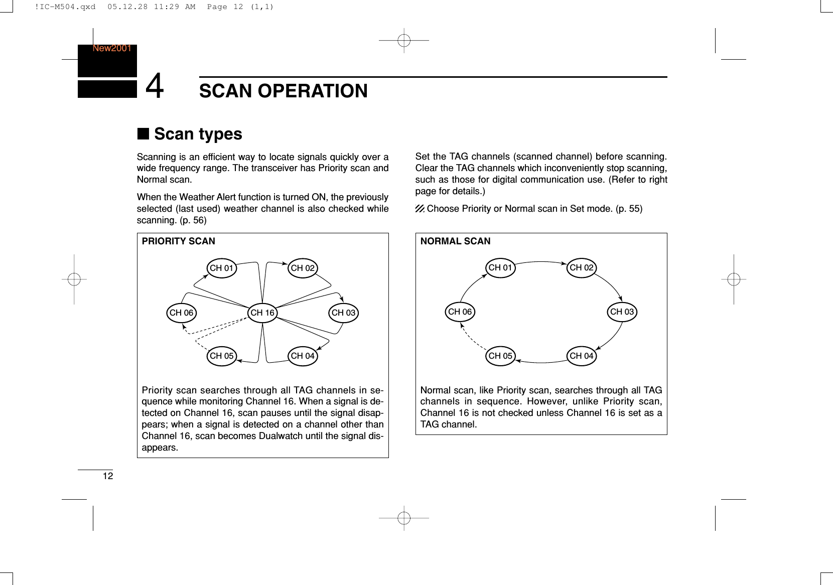
![134SCAN OPERATIONNew20014■Setting TAG channelsFor more efficient scanning, add the desired channels as TAGchannels or clear the TAG for unwanted channels. Channels that are not tagged will be skipped during scanning.TAG channels can be assigned to each channel group (USA,INT, CAN) independently.qWhile pushing and holding [H/L], push [CH/WX•DUAL•U/I/C]to select the desired channel group (USA, INT or CAN.)wSelect the desired channel to be set as a TAG channel.ePush [SCAN•TAG] for 1 sec. to set the displayed channelas a TAG channel.•“TTAAGG” appears in the display.rTo cancel the TAG channel setting, repeat step e.•“TTAAGG” disappears.✔Clearing (or setting) all tagged channelsWhile pushing and holding [H/L], push [SCAN•TAG] for 3sec. (until a long beep changes to 2 short beeps) to clear allTAG channels setting in the channel group.• Repeat above procedure to set all TAG channels.■Starting a scanSet scan type (Priority or Normal scan) and scan resumetimer in advance, using Set mode. (p. 55)qWhile pushing and holding [H/L], push [CH/WX•DUAL•U/I/C] to select the desired channel group (USA, INT,CAN) if desired.wSet TAG channels as described at left.eMake sure the squelch is closed to start a scan.rPush [SCAN•TAG] to start Priority or Normal scan.•“PPRRII--SSCCAANN 1166” appears at the channel comment indicatorduring Priority scan.•“NNOORRMMAALL SSCCAANN” appears at the channel comment indicatorduring Normal scan.• When a signal is detected, scan pauses until the signal disap-pears or resumes after pausing 5 sec. according to Set modesetting. (Channel 16 is still monitored during Priority scan.)• Rotate [DIAL] to check the scanning TAG channels, to changethe scanning direction or resume the scan manually.• A beep tone sounds and “16” blinks at the channel comment in-dicator when a signal is received on Channel 16 during Priorityscan.PushScan starts. When a signal is received25W25W INTINTDUPDUP3434°34.506N34.506N123123°23.236W23.236WUTCUTC 1212:00:00 INTLINTLBUSYBUSY 25W25W INTINTDUPDUPNORMALNORMAL SCANSCAN3434°34.506N34.506N123123°23.236W23.236WUTCUTC 1212:00:00 SAFETYSAFETY25W25W INTINTDUPDUPTAGTAGNORMALNORMAL SCANSCAN3434°34.506N34.506N123123°23.236W23.236WUTCUTC 1212:00:00[Example]: Starting a normal scan.!IC-M504.qxd 05.12.28 11:29 AM Page 13 (1,1)](https://usermanual.wiki/ICOM-orporated/291400/User-Guide-634763-Page-19.png)
![14DUALWATCH/TRI-WATCHNew20015■DescriptionDualwatch monitors Channel 16 while you are receiving another channel; Tri-watch monitors Channel 16 and the callchannel while receiving another channel. Dualwatch/Tri-watchis convenient for monitoring Channel 16 when you are oper-ating on another channel.■OperationqSelect Dualwatch or Tri-watch in Set mode. (p. 56)wRotate [DIAL] to select the desired operating channel.ePush [CH/WX•DUAL•U/I/C] for 1 sec. to start Dualwatchor Tri-watch.•“DDUUAALL 1166” appears during Dualwatch; “TTRRII 1166” appears dur-ing Tri-watch.• A beep tone sounds when a signal is received on Channel 16.rTo cancel Dualwatch/Tri-watch, push [CH/WX•DUAL•U/I/C]again.DUALWATCH/TRI-WATCH SIMULATION• If a signal is received on Channel 16, Dualwatch/Tri-watchpauses on Channel 16 until the signal disappears.• If a signal is received on the call channel during Tri-watch,Tri-watch becomes Dualwatch until the signal disappears.• To transmit on the selected channel during Dualwatch/Tri-watch, push and hold [PTT].Dualwatch Tri-watchCall channel[Example]: Operating Tri-watch on INT Channel 2525W25W INTINTDUPDUPTRITRI 16163434°34.506N34.506N123123°23.236W23.236WUTCUTC 1212:00:00 TELEPHONETELEPHONEBUSYBUSY 25W25W INTINT CALLCALLTAGTAGTRITRI 16163434°34.506N34.506N123123°23.236W23.236WUTCUTC 1212:00:00 CALLINGCALLINGTri-watch starts. Signal is received on call channel.BUSYBUSY 25W25W INTINTDUPDUPTRITRI 16163434°34.506N34.506N123123°23.236W23.236WUTCUTC 1212:00:00 TELEPHONETELEPHONESignal received on Channel 16 takes priority.25W25W INTINTDUPDUPTRITRI 16163434°34.506N34.506N123123°23.236W23.236WUTCUTC 1212:00:00 TELEPHONETELEPHONETri-watch resumes after the signal disappears.!IC-M504.qxd 05.12.28 11:29 AM Page 14 (1,1)](https://usermanual.wiki/ICOM-orporated/291400/User-Guide-634763-Page-20.png)
![156DSC OPERATION56■MMSI code programmingThe 9-digit MMSI (Maritime Mobile Service Identity: DSC selfID) code can be programmed at power ON.This code programming can be performed only twice.qTurn power OFF.wWhile pushing [MENU], turn power ON to enter MMSIcode programming condition.eAfter the display appears, release [MENU].rPush [MENU] again to enter the DSC menu.tRotate [DIAL] to select “SSeett uupp,” push [DIAL•ENTER].yRotate [DIAL] to select “MMMMSSII CChheecckk,” push[DIAL•ENTER].uRotate [DIAL]to setthe specific 9-digit MMSI code.• Push [16•9] or [CH/WX•DUAL•U/I/C] to move the cursor forwardor backward, respectively.• Push [CLR] to cancel and exit the condition to the set up menu.iAfter input the 9-digit code, push [DIAL•ENTER] to set thecode.• Returns to the set up menu.oPush [CLR] or rotate [DIAL] to select “EExxiitt,” push[DIAL•ENTER].• Returns to the DSC menu.• Repeat again to return to the normal operation condition.--DSC--DSC Menu--Menu--MMSI CheckMMSI Check__________________<CLR<CLR˘ExitExit /ENTENT˘OK>OK>--DSC--DSC Menu--Menu--SetSet upupAdd:INDVAdd:INDV IDIDAdd:GroupAdd:Group IDIDDEL:INDVDEL:INDV IDIDDEL:GroupDEL:Group IDIDOffsetOffset TimeTime˘MMSIMMSI CheckCheck--DSC--DSC Menu--Menu--SelectSelect ItemItemPositionPosition InputInputReceivedReceived CallsCalls˘SetSet upupExitExit!IC-M504.qxd 05.12.28 11:29 AM Page 15 (1,1)](https://usermanual.wiki/ICOM-orporated/291400/User-Guide-634763-Page-21.png)
![166DSC OPERATIONNew2001■MMSI code checkThe 9-digit MMSI (DSC self ID) code can be checked.qPush [MENU] to enter the DSC menu.wRotate [DIAL] to select “SSeett uupp,” push [DIAL•ENTER].eRotate [DIAL]to select “MMMMSSII CChheecckk,” push [DIAL•ENTER].rCheck the 9-digit MMSI (DSC self ID) code.tPush [CLR] or rotate [DIAL] to select “EExxiitt,” push [DIAL•ENTER].• Returns to the DSC menu.• Repeat again to return to the normal operation condition.--DSC Menu--MMSI Check123456789<CLR˘Exit>--DSC Menu--Set upDEL:Group IDOffset Time˘MMSI CheckAuto ACKNMEA OutputExit--DSC Menu--Select ItemPosition ReportPolling RequestReceived CallsDistress Setting˘Set upExit!IC-M504.qxd 05.12.28 11:29 AM Page 16 (1,1)](https://usermanual.wiki/ICOM-orporated/291400/User-Guide-634763-Page-22.png)
![176DSC OPERATIONNew20016■DSC address IDA total of 100 DSC address IDs can be programmed andnamed with up to 10 characters.DDProgramming Individual IDqPush [MENU] to enter the DSC menu.wRotate [DIAL] to select “SSeett uupp,” push [DIAL•ENTER].eRotate [DIAL]to select “AAdddd::IINNDDVV IIDD,” push [DIAL•ENTER].rRotate [DIAL]to set the individual ID and ID name.• Push [16•9] or [CH/WX•DUAL•U/I/C] to move the cursor forwardor backward, respectively.• Push [CLR] to cancel and exit the condition to the set up menu.• “FFuullll IIDD” appears when 100 DSC address IDs are alreadyset.• After inputting the 9-digit ID code, push [DIAL•ENTER] or [16•9]to set up a 10-character ID name.tAfter inputting, push [DIAL•ENTER] to program.yPush [CLR] or rotate [DIAL] to select “EExxiitt,” push [DIAL•ENTER].• Returns to the DSC menu.• Repeat again to return to the normal operation condition.--DSC Menu--Add:Individual IDInput 9 digits_________Input name_________<CLR˘Exit / ENT˘OK>--DSC Menu--Set up˘Add:INDV IDAdd:Group IDDEL:INDV IDDEL:Group IDOffset TimeMMSI Check--DSC Menu--Select ItemPosition ReportPolling RequestReceived CallsDistress Setting˘Set upExit!IC-M504.qxd 05.12.28 11:29 AM Page 17 (1,1)](https://usermanual.wiki/ICOM-orporated/291400/User-Guide-634763-Page-23.png)
![186DSC OPERATIONNew2001DDDeleting Individual IDqPush [MENU] to enter the DSC menu.wRotate [DIAL] to select “SSeett uupp,” push [DIAL•ENTER].eRotate [DIAL]to select “DDEELL::IINNDDVV IIDD,” push [DIAL•ENTER].• When no address ID is programmed, “NNoo IIDD” is displayed.Push [CLR] to exit the condition.rRotate [DIAL] to select the desired ID name for deleting.tPush [DIAL•ENTER] to delete the address ID and returnsto the set up menu.yPush [CLR] or rotate [DIAL] to select “EExxiitt,” push [DIAL•ENTER].• Returns to the DSC menu.• Repeat again to return to the normal operation condition.--DSC Menu--Select IDJohnPaul˘GeorgeMichael<CLR˘Exit / ENT˘OK>--DSC Menu--Set upAdd:INDV IDAdd:Group ID˘DEL:INDV IDDEL:Group IDOffset TimeMMSI Check--DSC Menu--Select ItemPosition ReportPolling RequestReceived CallsDistress Setting˘Set upExit!IC-M504.qxd 05.12.28 11:29 AM Page 18 (1,1)](https://usermanual.wiki/ICOM-orporated/291400/User-Guide-634763-Page-24.png)
![196DSC OPERATIONNew20016DDProgramming Group IDqPush [MENU] to enter the DSC menu.wRotate [DIAL] to select “SSeett uupp,” push [DIAL•ENTER].eRotate [DIAL]to select “AAdddd::GGrroouupp IIDD,” push [DIAL•ENTER].rRotate [DIAL]to set the group ID and ID name.• Push [16•9] or [CH/WX•DUAL•U/I/C] to move the cursor forwardor backward, respectively.• Push [CLR] to cancel and exit the condition to the set up menu.• “FFuullll IIDD” appears when 100 DSC address IDs are alreadyset.• After inputting the 8-digit ID code, push [DIAL•ENTER] or [16•9]to set up a 10-character ID name.• 1st digit ‘0’ is fixed for a group ID.tAfter inputting, push [DIAL•ENTER] to program.yPush [CLR] or rotate [DIAL] to select “EExxiitt,” push [DIAL•ENTER].• Returns to the DSC menu.• Repeat again to return to the normal operation condition.--DSC Menu--Add:Group IDInput 8 digits0________Input name_________<CLR˘Exit / ENT˘OK>--DSC Menu--Set upAdd:INDV ID˘Add:Group IDDEL:INDV IDDEL:Group IDOffset TimeMMSI Check--DSC Menu--Select ItemPosition ReportPolling RequestReceived CallsDistress Setting˘Set upExit!IC-M504.qxd 05.12.28 11:29 AM Page 19 (1,1)](https://usermanual.wiki/ICOM-orporated/291400/User-Guide-634763-Page-25.png)
![206DSC OPERATIONNew2001DDDeleting Group IDqPush [MENU] to enter the DSC menu.wRotate [DIAL] to select “SSeett uupp,” push [DIAL•ENTER].eRotate [DIAL]to select “DDEELL::GGrroouupp IIDD,” push [DIAL•ENTER].• When no address ID is programmed, “NNoo IIDD” is displayed.Push [CLR] to exit the condition.rRotate [DIAL] to select the desired ID name for deleting.tPush [DIAL•ENTER] to delete the group ID and returns tothe set up menu.yPush [CLR] or rotate [DIAL] to select “EExxiitt,” push [DIAL•ENTER].• Returns to the DSC menu.• Repeat again to return to the normal operation condition.--DSC Menu--Select IDIcomGroup A˘Group BGroup C<CLR˘Exit / ENT˘OK>--DSC Menu--Set upAdd:INDV IDAdd:Group IDDEL:INDV ID˘DEL:Group IDOffset TimeMMSI Check--DSC Menu--Select ItemPosition ReportPolling RequestReceived CallsDistress Setting˘Set upExit!IC-M504.qxd 05.12.28 11:29 AM Page 20 (1,1)](https://usermanual.wiki/ICOM-orporated/291400/User-Guide-634763-Page-26.png)
![216DSC OPERATIONNew20016■Position and time programmingA distress call should include the ship’s position and timedata. If no GPS is connected, your position and UTC (Univer-sal Time Coordinated) time should be input manually. Theyare included automatically when a GPS receiver (NMEA0183ver. 2.0 or 3.01) is connected.qPush [MENU] to enter the DSC menu.wRotate [DIAL] to select “PPoossiittiioonn IInnppuutt,” and push[DIAL•ENTER].eThe position information appears. Set your position (lati-tude and longitude) data with rotating [DIAL].• Push [16•9] or [CH/WX•DUAL•U/I/C] to move the cursor forwardor backward, respectively.• Rotate [DIAL] to edit N; North latitude or S; South latitude whenthe cursor is on the ‘N’ or ‘S’ position, and W; West longitude orE; East longitude when the cursor is on the ‘W’ or ‘E’ position.• Push [CLR] for 1 sec. to clear the latitude/longitudedata.• Push [CLR] to cancel and exit the condition to the DSC menu.rAfter setting the position data, push [DIAL•ENTER] to setthe time information appears. Set the current UTC timewith rotating [DIAL], then push [DIAL•ENTER].• Push [16•9] or [CH/WX•DUAL•U/I/C] to move the cursor forwardor backward, respectively.• Push [CLR] for 1 sec. to clear the UTC time data.• Push [CLR] to cancel and exit the condition to the DSC menu.--DSC Menu--Input UTC Time__:__ Null<CLR<CLR 1sec1sec˘NullNull Data>Data><CLR<CLR˘ExitExit /ENTENT˘OK>OK>--DSC Menu--Input PositionLatitude__°__.___N NullLongitude__°__.___W Null<CLR<CLR 1sec1sec˘NullNull Data>Data><CLR<CLR˘ExitExit /ENTENT˘OK>OK>--DSC Menu--Select Item˘Position InputIndividual CallGroup CallAll Ships CallPosition RequestPosition Report!IC-M504.qxd 05.12.28 11:29 AM Page 21 (1,1)](https://usermanual.wiki/ICOM-orporated/291400/User-Guide-634763-Page-27.png)
![tPush [CLR] or rotate [DIAL] to select “EExxiitt,” push[DIAL•ENTER].• Returns to the DSC menu.• Repeat again to return to the normal operation condition.Manually programmed position data will be held for 23.5hours only.■Position and time indicationWhen a GPS receiver (NMEA0183 ver. 2.0 or 3.01) is con-nected, the transceiver displays the current position and time.When no GPS receiver is connected, the transceiver displaysthe manually entered position and time.A GPS receiver appropriate for the IC-M504 is not suppliedfrom Icom. A GPS receiver with NMEA0183 ver. 2.0 or 3.01format is required for position and time indication. Ask yourdealer about suitable GPS receivers.➥When connecting GPS receiver is compatible with sev-eral sentence formatters, the order of input precedenceis ‘RMC,’ ‘GGA,’ ‘GNS’ and ‘GLL.’➥When sentence formatter ‘RMC’ is received, time indi-cation includes a date and UTC time only.➥“????” may blink instead of position and time indicationswhen the GPS data is invalid, or has not been manuallyupdated after 4 hours.25W INTTAG34°34.506N123°23.236WUTC 12:00 CALLING226DSC OPERATIONNew2001!IC-M504.qxd 05.12.28 11:29 AM Page 22 (1,1)](https://usermanual.wiki/ICOM-orporated/291400/User-Guide-634763-Page-28.png)
![236DSC OPERATIONNew20016■Distress callA distress call should be transmitted, if in the opinion of theMaster, the ship or a person is in distress and requires imme-diate assistance.NEVER USE THE DISTRESS CALL WHEN YOURSHIP OR A PERSON IS NOT IN AN EMERGENCY.A DISTRESS CALL CAN BE USED ONLY WHENIMMEDIATE HELP IS NEEDED.DDSimple callqConfirm no distress call is being received.wWhile lifting up the key cover, push [DISTRESS] for 5 sec. to transmit the distress call.• Emergency channel (Channel 70) is automatically selected andthe distress call is transmitted.• When no GPS is connected, input your position and UTC time, ifpossible.• While pushing [DISTRESS], the key backlighting is blinking.eAfter transmitting the distress call, the transceiver waits foran acknowledgment call on Channel 70.• The distress call is automatically transmitted every 3.5 to 4.5minutes.• After 2 sec., the transceiver is set to Channel 16 automatically.rAfter receiving the acknowledgment, reply using the mi-crophone.25W INTTAGReceivedDistressACK<Osaka Bay<CLR˘Beep Off> CALLINGDistress CallTX CompleteNow Waiting for ACK<CLR<CLR˘CancelCancel ACK>ACK>After 2 sec.25W INTTAGWait ACK<CLR˘Cancel ACK> CALLINGDistress CallPush for 5 sec.!IC-M504.qxd 05.12.28 11:29 AM Page 23 (1,1)](https://usermanual.wiki/ICOM-orporated/291400/User-Guide-634763-Page-29.png)
![246DSC OPERATIONNew2001➥A distress alert contains (default);• Nature of distress : Undesignated distress• Position data : GPS or manual input position data heldfor 23.5 hrs or until the power is turnedOFF.➥The distress call is repeated every 3.5–4.5 min., until re-ceiving an ‘acknowledgement.’➥Push [CLR] to cancel the ‘Call repeat’ mode.➥“??” may blink instead of position and time indicationswhen the GPS data is invalid, or has not been manuallyupdated after 4 hours.DDRegular callThe nature of the distress call should be included in the dis-tress call.qPush [MENU] to enter the DSC menu.wRotate [DIAL] to select “DDiissttrreessss SSeettttiinngg,” andpush [DIAL•ENTER].eRotate [DIAL] to select the nature of the distress, push[DIAL•ENTER].•‘UUnnddeessiiggnnaatteedd,’ ‘EExxpplloossiioonn,’ ‘FFllooooddiinngg,’ ‘CCoollllii--ssiioonn,’ ‘GGrroouunnddiinngg,’ ‘CCaappssiizziinngg,’ ‘SSiinnkkiinngg,’‘AAddrriifftt(Disable adrift),’ ‘AAbbaannddoonniinngg(Abandoning ship),’‘PPiirraaccyy(Piracy attack)’ and ‘MMOOBB(Man overboard)’ are avail-able.• The selected nature of the distress is stored for 10 minutes.--DSC Menu--Select NatureUndesignated˘ExplosionFloodingCollision<CLR<CLR˘ExitExit /ENTENT˘OK>OK>--DSC Menu--Select ItemAll Ships CallPosition RequestPosition ReportPolling RequestReceived Calls˘Distress Setting!IC-M504.qxd 05.12.28 11:29 AM Page 24 (1,1)](https://usermanual.wiki/ICOM-orporated/291400/User-Guide-634763-Page-30.png)
![256DSC OPERATIONNew20016When a GPS receiver (NMEA0183 ver. 2.0 or 3.01) is con-nected, next steps r, t(Current position/time program-ming) do not appear. Go to step y.rThe position information appears. Set your position (lati-tude and longitude) data with rotating [DIAL].• Push [16•9] or [CH/WX•DUAL•U/I/C] to move the cursor forwardor backward, respectively.• Rotate [DIAL] to edit N; North latitude or S; South latitude whenthe cursor is on the ‘N’ or ‘S’ position, and W; West longitude orE; East longitude when the cursor is on the ‘W’ or ‘E’ position.• Push [CLR] for 1 sec. to clear the latitude/longitudedata.• Push [CLR] to cancel and exit the condition to the DSC menu.tAfter setting the position data, push [DIAL•ENTER] to setthe time information appears. Set the current UTC timewith rotating [DIAL], then push [DIAL•ENTER].• Push [16•9] or [CH/WX•DUAL•U/I/C] to move the cursor forwardor backward, respectively.• Push [CLR] for 1 sec. to clear the UTC time data.• Push [CLR] to cancel and exit the condition to the DSC menu.yPush [DISTRESS] for 5 sec. to transmit the distress call.• While pushing [DISTRESS], the key backlighting is blinking.uAfter transmitting the distress call, the transceiver waits foran acknowledgment call on Channel 70.• The distress call is automatically transmitted every 3.5 to 4.5 min.• After 2 sec., the transceiver is set to Channel 16 automatically.Distress CallTX CompleteNow Waiting for ACK<CLR<CLR˘CancelCancel ACK>ACK>After 2 sec.25W INTTAGWait ACK<CLR˘Cancel ACK> CALLING--DSC Menu--Input UTC Time__:__ Null<CLR<CLR 1sec1sec˘NullNull Data>Data><CLR<CLR˘ExitExit /ENTENT˘OK>OK>--DSC Menu--Input PositionLatitude__°__.___N NullLongitude__°__.___W Null<CLR<CLR 1sec1sec˘NullNull Data>Data><CLR<CLR˘ExitExit /ENTENT˘OK>OK>!IC-M504.qxd 05.12.28 11:29 AM Page 25 (1,1)](https://usermanual.wiki/ICOM-orporated/291400/User-Guide-634763-Page-31.png)
![266DSC OPERATIONNew2001iAfter receiving the acknowledgment, reply using the mi-crophone.➥A distress alert contains (default);• Nature of distress : Selected nature of the distress• Position data : GPS or manual input position data heldfor 23.5 hrs or until the power is turnedOFF.➥The distress call is repeated every 3.5–4.5 min., until re-ceiving an ‘acknowledgement.’➥Push [CLR] to cancel the ‘Call repeat’ mode.➥“????” may blink instead of position and time indicationswhen the GPS data is invalid, or has not been manuallyupdated after 4 hours.■Transmitting DSC callsTo ensure correct operation of the DSC function, pleasemake sure you set the squelch correctly. (p. 8)DDTransmitting an individual callThe individual call function allows you to transmit a DSC sig-nal to a specific ship only.qPush [MENU] to enter the DSC menu.wRotate [DIAL] to select “IInnddiivviidduuaall CCaallll,” push[DIAL•ENTER].•“PPoossiittiioonn IInnppuutt” item appears when a GPS receiver(NMEA0183 ver. 2.0 or 3.01) is not connected.--DSC Menu--Select ItemPosition Input˘Individual CallGroup CallAll Ships CallPosition RequestPosition Report25W INTTAGReceivedDistressACK<Osaka Bay<CLR˘Beep Off> CALLING!IC-M504.qxd 05.12.28 11:29 AM Page 26 (1,1)](https://usermanual.wiki/ICOM-orporated/291400/User-Guide-634763-Page-32.png)
![276DSC OPERATIONNew20016eRotate [DIAL] to select the desired pre-programmed indi-vidual address or “MMaannuuaall IInnppuutt,” push[DIAL•ENTER].• The ID code for the individual call can be set in advance. (p. 16)• When “MMaannuuaall IInnppuutt” is selected, set the 9-digit ID codefor the individual you wish to call with rotating [DIAL].1st digit must not be ‘0’.rRotate [DIAL] to select a desired intership channel, push[DIAL•ENTER].• Intership channels are already preset into the transceiver in rec-ommending order.tPush [DIAL•ENTER] to transmit the individual call.• If Channel 70 is busy, the transceiver stands by until the channelbecomes clear.--DSC Menu--Individual CallTransmitting--DSC Menu--Select Intership CH˘08697706<CLR˘Exit / ENT˘OK>--DSC Menu--Individual Call Ready<CLR˘Exit / ENT˘OK>--DSC Menu--Select AddressManual InputJohn˘PaulGeorgeMichael<CLR˘Exit / ENT˘OK>!IC-M504.qxd 05.12.28 11:29 AM Page 27 (1,1)](https://usermanual.wiki/ICOM-orporated/291400/User-Guide-634763-Page-33.png)
![286DSC OPERATIONNew2001yStandby on Channel 70 until an acknowledgement is re-ceived.uWhen the acknowledgement ‘Able to comply’ is received,the specified channel (in step r) is selected with beepsautomatically. Or, when the acknowledgement ‘Unable tocomply’ is received, the display returns to the operatedchannel (before enter the DSC menu) with beeps.iPush [CLR] to stop the beep, then push and hold [PTT] tocommunicate your message to the responding ship.DDTransmitting an individual acknowledgementWhen receiving an individual call, you can transmit an ac-knowledgement (‘Able to comply’ or ‘Unable to comply’) byusing the on screen prompts (see page 38 for details). Alter-natively, you can send an acknowledgement through themenu system as follows.qPush [MENU] to enter the DSC menu.wRotate [DIAL] to select “IInnddiivviidduuaall AACCKK,” push[DIAL•ENTER].•“PPoossiittiioonn IInnppuutt” item appears when a GPS receiver(NMEA0183 ver. 2.0 or 3.01) is not connected.•“IInnddiivviidduuaall AACCKK” item appears after an individual call isreceived.eRotate [DIAL] to select the desired individual address orID code, push [DIAL•ENTER].--DSC Menu--Select AddressJohn˘PaulGeorgeMichael<CLR˘Exit / ENT˘OK>--DSC Menu--Select ItemPosition InputIndividual Call˘Individual ACKGroup CallAll Ships CallPosition Request25W INTReceivedINDV ACK<John<CLR˘Beep Off> COMMERCIAL25W INTDUPReceivedUnable ACK<John<CLR˘Beep Off> INTL--DSC Menu--Individual CallTX CompleteNow Waiting for ACK<CLR˘Exit>!IC-M504.qxd 05.12.28 11:29 AM Page 28 (1,1)](https://usermanual.wiki/ICOM-orporated/291400/User-Guide-634763-Page-34.png)
![296DSC OPERATIONNew20016rRotate [DIAL] to select that you can comply to the call ornot from “AAbbllee ttoo CCoommppllyy” or “UUnnaabbllee ttoo CCoomm--ppllyy,” push [DIAL•ENTER].• When “UUnnaabbllee ttoo CCoommppllyy” is selected, the reason “NoReason Given” will be transmitted.tPush [DIAL•ENTER] to transmit the acknowledgement callto the selected station.yAfter the individual acknowledgement call has been trans-mitted, the specified channel (specified by the calling sta-tion) is selected automatically when “AAbbllee ttoo CCoomm--ppllyy” is selected, or returns to the previous condition(before entering the DSC menu) when “UUnnaabbllee ttooCCoommppllyy” is selected in step r.DDTransmitting a group callThe group call function allows you to transmit a DSC signal toa specific group only.qPush [MENU] to enter the DSC menu.wRotate [DIAL] to select “GGrroouupp CCaallll,” push [DIAL•ENTER].•“PPoossiittiioonn IInnppuutt” item appears when a GPS receiver(NMEA0183 ver. 2.0 or 3.01) is not connected.eRotate [DIAL] to select the desired pre-programmed groupaddress or “MMaannuuaall IInnppuutt,” push [DIAL•ENTER].• The ID code for the group call can be set in advance. (p. 18)• When “MMaannuuaall IInnppuutt” is selected, set the 8-digit ID codefor the group you wish to call with rotating [DIAL].--DSC Menu--Select AddressManual Input˘IcomCoast station<CLR˘Exit / ENT˘OK>--DSC Menu--Select ItemPosition InputIndividual Call˘Group CallAll Ships CallPosition RequestPosition Report--DSC Menu--Select Action˘Able to ComplyUnable to Comply<CLR˘Exit / ENT˘OK>--DSC Menu--Individual ACK Ready<CLR˘Exit / ENT˘OK>!IC-M504.qxd 05.12.28 11:29 AM Page 29 (1,1)](https://usermanual.wiki/ICOM-orporated/291400/User-Guide-634763-Page-35.png)
![306DSC OPERATIONNew2001rRotate [DIAL] to select a desired intership channel, push[DIAL•ENTER].• Intership channels are already preset into the transceiver in rec-ommending order.tPush [DIAL•ENTER] to transmit the group call.• If Channel 70 is busy, the transceiver stands by until the channelbecomes clear.yAfter the group call has been transmitted, the following in-dication is displayed.uPush [CLR] to exit the condition and selects the specifiedintership channel in step rautomatically.• Even if [CLR] hasn’t been pushed, the transceiver selects thespecified intership channel in step rautomatically after 2 sec. ofinactivity.--DSC Menu--Group CallTX Complete<CLR˘Exit>--DSC Menu--Group CallTransmitting--DSC Menu--Select Intership CH˘08697706<CLR˘Exit / ENT˘OK>--DSC Menu--Group Call Ready<CLR˘Exit / ENT˘OK>!IC-M504.qxd 05.12.28 11:29 AM Page 30 (1,1)](https://usermanual.wiki/ICOM-orporated/291400/User-Guide-634763-Page-36.png)
![316DSC OPERATIONNew20016DDTransmitting an all ships callLarge ships use Channel 70 as their ‘listening channel.’ Whenyou want to announce a message to these ships, use the allships call function.qPush [MENU] to enter the DSC menu.wRotate [DIAL] to select “AAllll SShhiippss CCaallll,” and push[DIAL•ENTER].•“PPoossiittiioonn IInnppuutt” item appears when a GPS receiver(NMEA0183 ver. 2.0 or 3.01) is not connected.eRotate [DIAL] to select the desired category, push[DIAL•ENTER].• Output power of ‘Routine’ category is 1 W (low power) only.• The selectable category may differ according to the programmedsetting. Ask your dealer for the available categories.rPush [DIAL•ENTER] to transmit the all ships call.• Channel 70 is selected and the all ships call is transmitted.--DSC Menu--All Ships CallTransmitting--DSC Menu--Select Category˘RoutineSafetyUrgency<CLR˘Exit / ENT˘OK>--DSC Menu--All Ships Call Ready<CLR˘Exit / ENT˘OK>--DSC Menu--Select ItemPosition InputIndividual CallGroup Call˘All Ships CallPosition RequestPosition Report!IC-M504.qxd 05.12.28 11:29 AM Page 31 (1,1)](https://usermanual.wiki/ICOM-orporated/291400/User-Guide-634763-Page-37.png)
![326DSC OPERATIONNew2001tAfter the all ships call has been transmitted, the followingindication is displayed.yPush [CLR] to exit the condition and selects Channel 16automatically.• Even if [CLR] hasn’t been pushed, the transceiver automaticallyselects Channel 16 after 2 sec. of inactivity.DDTransmitting a position request callTransmit a position request call when you want to know aspecific ship’s current position, etc.qPush [MENU] to enter the DSC menu.wRotate [DIAL] to select “PPoossiittiioonn RReeqquueesstt,” push[DIAL•ENTER].•“PPoossiittiioonn IInnppuutt” item appears when a GPS receiver(NMEA0183 ver. 2.0 or 3.01) is not connected.eRotate [DIAL] to select the desired pre-programmed indi-vidual address or “MMaannuuaall IInnppuutt,” push[DIAL•ENTER].• The ID code can be set in advance. (p. 17)• When “MMaannuuaall IInnppuutt” is selected, set the 9-digit ID codefor the individual you wish to call with rotating [DIAL].--DSC Menu--Select ItemPosition InputIndividual CallGroup CallAll Ships Call˘Position RequestPosition Report--DSC Menu--All Ships CallTX Complete<CLR˘Exit>!IC-M504.qxd 05.12.28 11:29 AM Page 32 (1,1)](https://usermanual.wiki/ICOM-orporated/291400/User-Guide-634763-Page-38.png)
![336DSC OPERATIONNew20016rPush [DIAL•ENTER] to transmit the position request call.• If Channel 70 is busy, the transceiver stands by until the channelbecomes clear.tAfter the position request call has been transmitted, the fol-lowing indication is displayed.yPush [CLR] to return to the previous indication before en-tering the DSC menu.• Even if [CLR] hasn’t been pushed, the display automatically re-turns to the previous indication after 2 sec. of inactivity.--DSC Menu--Position RequestTX CompleteNow Waiting for ACK<CLR˘Exit>--DSC Menu--Position RequestTransmitting--DSC Menu--Select AddressManual InputJohn˘PaulGeorgeMichael<CLR˘Exit / ENT˘OK>--DSC Menu--POS Request Ready<CLR˘Exit / ENT˘OK>!IC-M504.qxd 05.12.28 11:29 AM Page 33 (1,1)](https://usermanual.wiki/ICOM-orporated/291400/User-Guide-634763-Page-39.png)
![346DSC OPERATIONNew2001DDTransmitting a position report callTransmit a position report call when you want to announceyour own position to a specific ship and to get an answer, etc.qPush [MENU] to enter the DSC menu.wRotate [DIAL] to select “PPoossiittiioonn RReeppoorrtt,” push[DIAL•ENTER].•“PPoossiittiioonn IInnppuutt” item appears when a GPS receiver(NMEA0183 ver. 2.0 or 3.01) is not connected.eRotate [DIAL] to select the desired pre-programmed indi-vidual address or “MMaannuuaall IInnppuutt,” push[DIAL•ENTER].• The ID code can be set in advance. (p. 17)• When “MMaannuuaall IInnppuutt” is selected, set the 9-digit ID codefor the individual you wish to call with rotating [DIAL].When a GPS receiver (NMEA0183 ver. 2.0 or 3.01) is con-nected, next steps r, t(Current position/time program-ming) do not appear. Go to step y.rThe position information appears. Set your position (lati-tude and longitude) data with rotating [DIAL].• Push [16•9] or [CH/WX•DUAL•U/I/C] to move the cursor forwardor backward, respectively.• Rotate [DIAL] to edit N; North latitude or S; South latitude whenthe cursor is on the ‘N’ or ‘S’ position, and W; West longitude orE; East longitude when the cursor is on the ‘W’ or ‘E’ position.• Push [CLR] for 1 sec. to clear the latitude/longitudedata.• Push [CLR] to cancel and exit the condition to the DSC menu.tAfter setting the position data, push [DIAL•ENTER] to setthe time information appears. Set the current UTC timewith rotating [DIAL], then push [DIAL•ENTER].• Push [16•9] or [CH/WX•DUAL•U/I/C] to move the cursor forwardor backward, respectively.• Push [CLR] for 1 sec. to clear the UTC time data.• Push [CLR] to cancel and exit the condition to the DSC menu.--DSC Menu--Input PositionLatitude__°__.___N NullLongitude__°__.___W Null<CLR<CLR 1sec1sec˘NullNull Data>Data><CLR<CLR˘ExitExit /ENTENT˘OK>OK>--DSC Menu--Select AddressManual InputJohn˘PaulGeorgeMichael<CLR˘Exit / ENT˘OK>--DSC Menu--Select ItemPosition InputIndividual CallGroup CallAll Ships CallPosition Request˘Position Report!IC-M504.qxd 05.12.28 11:29 AM Page 34 (1,1)](https://usermanual.wiki/ICOM-orporated/291400/User-Guide-634763-Page-40.png)
![356DSC OPERATIONNew20016yPush [DIAL•ENTER] to transmit the position report call.• If Channel 70 is busy, the transceiver stands by until the channelbecomes clear.uAfter the position report call has been transmitted, the fol-lowing indication is displayed.iPush [CLR] to return to the previous indication before en-tering the DSC menu.• Even if [CLR] hasn’t been pushed, the display automatically re-turns to the previous indication after 2 sec. of inactivity.--DSC Menu--Position ReportTX CompleteNow Waiting for ACK<CLR˘Exit>--DSC Menu--Position ReportTransmitting--DSC Menu--Input UTC Time__:__ Null<CLR<CLR 1sec1sec˘NullNull Data>Data><CLR<CLR˘ExitExit /ENTENT˘OK>OK>--DSC Menu--Position Report Ready<CLR˘Exit / ENT˘OK>!IC-M504.qxd 05.12.28 11:29 AM Page 35 (1,1)](https://usermanual.wiki/ICOM-orporated/291400/User-Guide-634763-Page-41.png)
![366DSC OPERATIONNew2001DDTransmitting a polling request callTransmit a polling request call when you want to know a spe-cific ship is in the communication area, etc.qPush [MENU] to enter the DSC menu.wRotate [DIAL] to select “PPoolllliinngg RReeqquueesstt,” push[DIAL•ENTER].eRotate [DIAL] to select the desired pre-programmed indi-vidual address or “MMaannuuaall IInnppuutt,” push[DIAL•ENTER].• The ID code can be set in advance. (p. 17)• When “MMaannuuaall IInnppuutt” is selected, set the 9-digit ID codefor the individual you wish to call with rotating [DIAL].rPush [DIAL•ENTER] to transmit the polling request call.• If Channel 70 is busy, the transceiver stands by until the channelbecomes clear.--DSC Menu--Polling RequestTransmitting--DSC Menu--Select AddressManual InputJohn˘PaulGeorgeMichael<CLR˘Exit / ENT˘OK>--DSC Menu--Polling Request Ready<CLR˘Exit / ENT˘OK>--DSC Menu--Select ItemIndividual CallGroup CallAll Ships CallPosition RequestPosition Report˘Polling Request!IC-M504.qxd 05.12.28 11:29 AM Page 36 (1,1)](https://usermanual.wiki/ICOM-orporated/291400/User-Guide-634763-Page-42.png)
![376DSC OPERATIONNew20016tAfter the polling request call has been transmitted, the fol-lowing indication is displayed.yPush [CLR] to return to the previous indication before en-tering the DSC menu.• Even if [CLR] hasn’t been pushed, the display automatically re-turns to the previous indication after 2 sec. of inactivity.DDTransmitting a position request reply callTransmit a position request reply call when a position requestcall is received.qPush [MENU] to enter the DSC menu.wRotate [DIAL] to select “PPoossiittiioonn RReeppllyy,” push[DIAL•ENTER].•“PPoossiittiioonn RReeppllyy” item appears after a position requestcall is received.eRotate [DIAL] to select the desired individual address orID code, push [DIAL•ENTER].--DSC Menu--Select AddressJohn˘PaulGeorgeMichael<CLR˘Exit / ENT˘OK>--DSC Menu--Select ItemPosition InputIndividual CallGroup CallAll Ships CallPosition Request˘Position Reply--DSC Menu--Polling RequestTX CompleteNow Waiting for ACK<CLR˘Exit>!IC-M504.qxd 05.12.28 11:29 AM Page 37 (1,1)](https://usermanual.wiki/ICOM-orporated/291400/User-Guide-634763-Page-43.png)
![386DSC OPERATIONNew2001When a GPS receiver (NMEA0183 ver. 2.0 or 3.01) is con-nected, next steps r, t(Current position/time program-ming) do not appear. Go to step y.rThe position information appears. Set your position (lati-tude and longitude) data with rotating [DIAL].• Push [16•9] or [CH/WX•DUAL•U/I/C] to move the cursor forwardor backward, respectively.• Rotate [DIAL] to edit N; North latitude or S; South latitude whenthe cursor is on the ‘N’ or ‘S’ position, and W; West longitude orE; East longitude when the cursor is on the ‘W’ or ‘E’ position.• Push [CLR] for 1 sec. to clear the latitude/longitudedata.• Push [CLR] to cancel and exit the condition to the DSC menu.tAfter setting the position data, push [DIAL•ENTER] to setthe time information appears. Set the current UTC timewith rotating [DIAL], then push [DIAL•ENTER].• Push [16•9] or [CH/WX•DUAL•U/I/C] to move the cursor forwardor backward, respectively.• Push [CLR] for 1 sec. to clear the UTC time data.• Push [CLR] to cancel and exit the condition to the DSC menu.yPush [DIAL•ENTER] to transmit the position request replycall to the selected station.• Your position data is transmitted, when [DIAL•ENTER] ispushed.--DSC Menu--Position ReplyTransmitting--DSC Menu--Input UTC Time__:__ Null<CLR<CLR 1sec1sec˘NullNull Data>Data><CLR<CLR˘ExitExit /ENTENT˘OK>OK>--DSC Menu--Position Reply Ready<CLR˘Exit / ENT˘OK>--DSC Menu--Input PositionLatitude__°__.___N NullLongitude__°__.___W Null<CLR<CLR 1sec1sec˘NullNull Data>Data><CLR<CLR˘ExitExit /ENTENT˘OK>OK>!IC-M504.qxd 05.12.28 11:29 AM Page 38 (1,1)](https://usermanual.wiki/ICOM-orporated/291400/User-Guide-634763-Page-44.png)
![396DSC OPERATIONNew20016DDTransmitting a position report reply callTransmit a position report reply call when a position report callis received.qPush [MENU] to enter the DSC menu.wRotate [DIAL] to select “PPOOSS RReeppoorrtt RReeppllyy,” push[DIAL•ENTER].•“PPOOSS RReeppoorrtt RReeppllyy” item appears after a position reportcall is received.eRotate [DIAL] to select the desired individual address orID code, push [DIAL•ENTER].rPush [DIAL•ENTER] to transmit the position report replycall to the selected station.--DSC Menu--Position Report ReplyTransmitting--DSC Menu--Select AddressManual InputJohn˘PaulGeorgeMichael<CLR˘Exit / ENT˘OK>--DSC Menu--POS REP Reply Ready<CLR˘Exit / ENT˘OK>--DSC Menu--Select ItemIndividual CallGroup CallAll Ships CallPosition RequestPosition Report˘POS Report Reply!IC-M504.qxd 05.12.28 11:29 AM Page 39 (1,1)](https://usermanual.wiki/ICOM-orporated/291400/User-Guide-634763-Page-45.png)
![406DSC OPERATIONNew2001DDTransmitting a polling request reply callTransmit a polling reply call when a polling request call is re-ceived.qPush [MENU] to enter the DSC menu.wRotate [DIAL] to select “PPoolllliinngg RReeppllyy,” push [DIAL•ENTER].•“PPoolllliinngg RReeppllyy” item appears after a polling request callis received.eRotate [DIAL] to select the desired individual address orID code, push [DIAL•ENTER].rPush [DIAL•ENTER] to transmit the polling request call tothe selected station.--DSC Menu--Polling ReplyTransmitting--DSC Menu--Select AddressManual InputJohn˘PaulGeorgeMichael<CLR˘Exit / ENT˘OK>--DSC Menu--Polling Reply Ready<CLR˘Exit / ENT˘OK>--DSC Menu--Select ItemGroup CallAll Ships CallPosition RequestPosition ReportPolling Request˘Polling Reply!IC-M504.qxd 05.12.28 11:29 AM Page 40 (1,1)](https://usermanual.wiki/ICOM-orporated/291400/User-Guide-634763-Page-46.png)
![416DSC OPERATIONNew20016■Receiving DSC callsDDReceiving a distress callWhile monitoring Channel 70 and a distress call is received:➥The emergency alarm sounds for 2 minutes.• Push [CLR] to stop the alarm.➥“RReecceeiivveedd DDiissttrreessss” appears in the display, thenChannel 16 is automatically selected.➥Continue monitoring Channel 16 as a coast station may re-quire assistance.DDReceiving a distress acknowledgementWhile monitoring Channel 70 and a distress acknowledge-ment to other ship is received:➥The emergency alarm sounds for 2 minutes.• Push [CLR] to stop the alarm.➥“RReecceeiivveedd DDiissttrreessssAACCKK” appears in the display,then Channel 16 is automatically selected.DDReceiving a distress relay callWhile monitoring Channel 70 and a distress relay acknowl-edgement is received:➥The emergency alarm sounds for 2 minutes.• Push [CLR] to stop the alarm.➥“RReecceeiivveedd DDiissttrreessssRRLLYY” appears in the display,then Channel 16 is automatically selected.25W INTTAGReceivedDistressRLY<John<CLR˘Beep Off> CALLING25W INTTAGReceivedDistressACK<Osaka Bay<CLR˘Beep Off> CALLING25W INTTAGReceivedDistress<Paul<CLR˘Beep Off> CALLING!IC-M504.qxd 05.12.28 11:29 AM Page 41 (1,1)](https://usermanual.wiki/ICOM-orporated/291400/User-Guide-634763-Page-47.png)
![426DSC OPERATIONNew2001DDReceiving an individual callWhile monitoring Channel 70 and an individual call is re-ceived:➥The emergency alarm or beeps sound depending on thereceived category.➥“RReecceeiivveedd IInnddiivviidduuaall” appears in the display.➥Push [CLR] to stop the beep, then push [DIAL•ENTER] toreply the call and select the channel specified by the callingstation for voice communication (depending on your reply-ing condition see p. 28 for individual acknowledgement callprocedure for details.); push [CLR] to ignore the individualcall.DDReceiving a group callWhile monitoring Channel 70 and a group call is received:➥The emergency alarm or beeps sound depending on thereceived category.➥“RReecceeiivveedd GGrroouupp” appears in the display.➥Push [CLR] to stop the beep, then push [DIAL•ENTER] toselect the channel specified by the calling station for voicecommunication; push [CLR] to ignore the group call.DDReceiving an all ships callWhile monitoring Channel 70 and an all ships call is received:➥The emergency alarm sounds when the category is ‘Dis-tress’ or ‘Urgency’; beeps sound for 2 minutes.➥“RReecceeiivveedd AAllll SShhiippss” appears in the display.➥Push [CLR] to stop the beep, then push [DIAL•ENTER] tomonitor channel 16 for an announcement from the callingvessel, push [CLR] to ignore the call.25W INTTAGReceivedGroup<Icom<CLR˘Beep Off> SAFETY25W INTTAGReceivedIndividual<Paul<CLR˘Beep Off> SAFETY!IC-M504.qxd 05.12.28 11:29 AM Page 42 (1,1)](https://usermanual.wiki/ICOM-orporated/291400/User-Guide-634763-Page-48.png)
![436DSC OPERATIONNew20016DDReceiving a geographical area callWhile monitoring Channel 70 and a geographical area call(for the area you are in) is received:➥Emergency alarm or beeps sound depending on the re-ceived category.➥“RReecceeiivveedd GGeeooggrraapphhiicc” appears in the display.➥Push [CLR] to stop the beep, then push [DIAL•ENTER] tochange to the channel specified by the calling station forvoice communication; push other key to ignore the geo-graphical area call.➥Monitor the selected channel for an announcement fromthe calling station.When no GPS receiver is connected or if there is a prob-lem with the connected receiver, all geographical area callsare received, regardless of your position.DDReceiving a position request callWhile monitoring Channel 70 and a position request call is re-ceived:➥“RReecceeiivveedd PPOOSS RReeqquueesstt” appears in the display.➥Push [CLR] to stop the beep, then push [DIAL•ENTER] toreply to the position request call; push [CLR] to ignore theposition request call.DDReceiving a position report callWhile monitoring Channel 70 and a position report call is re-ceived:➥“RReecceeiivveedd PPOOSS RReeppoorrtt” appears in the display.➥Push [CLR] to stop the beep, then push [DIAL•ENTER] toreply to the position report call; push [CLR] to ignore theposition report call.25W INTTAGReceivedPOS Report<Paul<CLR˘Beep Off> SAFETY25W INTTAGReceivedPOS Request<Paul<CLR˘Beep Off> SAFETY25W INTTAGReceivedGeographic<Osaka Bay<CLR˘Beep Off> SAFETY25W INTTAGReceivedAll Ships<Paul<CLR˘Beep Off> SAFETY!IC-M504.qxd 05.12.28 11:29 AM Page 43 (1,1)](https://usermanual.wiki/ICOM-orporated/291400/User-Guide-634763-Page-49.png)
![446DSC OPERATIONNew2001DDReceiving a polling request callWhile monitoring Channel 70 and a polling request call is re-ceived:➥“RReecceeiivveedd PPOOLLLL RREEQQ” appears in the display.➥Push [CLR] to stop the beep, then push [DIAL•ENTER] toreply to the call; push [CLR] to ignore the call.DDReceiving a position request reply callWhile monitoring Channel 70 and a position request reply callis received:➥“RReecceeiivveedd PPOOSS RReeppllyy” appears in the display.➥Push [CLR] to stop the beep, then push [DIAL•ENTER] todisplay the position information; push [CLR] to ignore thereply call.DDReceiving a position report reply callWhile monitoring Channel 70 and a position report reply callis received:➥“RReecceeiivveedd PPOOSS RReeppllyy” appears in the display.➥Push [CLR] to stop the beep, then push [DIAL•ENTER] todisplay the position information; push [CLR] to ignore thereply call.DDReceiving a polling request reply callWhile monitoring Channel 70 and a polling request reply callis received:➥“RReecceeiivveedd PPOOLLLL RReeppllyy” appears in the display.➥Push [CLR] to stop the beep, then push [DIAL•ENTER] todisplay the position information; push [CLR] to ignore thereply call.25W INTTAGReceivedPOLL Reply<Paul<CLR˘Beep Off> SAFETY25W INTTAGReceivedPOS Reply<Paul<CLR˘Beep Off> SAFETY25W INTTAGReceivedPOS Reply<Paul<CLR˘Beep Off> SAFETY25W INTTAGReceivedPOLL REQ<Paul<CLR˘Beep Off> SAFETY!IC-M504.qxd 05.12.28 11:29 AM Page 44 (1,1)](https://usermanual.wiki/ICOM-orporated/291400/User-Guide-634763-Page-50.png)
![456DSC OPERATIONNew20016■Received messagesThe transceiver automatically stores up to 20 distress mes-sages and 20 other messages. The messages can be usedas an assistance to the logbook.qPush [MENU] to enter the DSC menu.wRotate [DIAL] to select “RReecceeiivveedd CCaallllss,” push[DIAL•ENTER].DDDistress messageqRotate [DIAL] to select “DDiissttrreessss,” push[DIAL•ENTER].wRotate [DIAL] to scroll to the desired message, push[DIAL•ENTER].• Messages which are blinking have not read.eRotate [DIAL] to scroll the message.rPush [CLR] to exit the condition or push [CLR] for 1 sec.to delete the displayed message and returns to DSCmenu.--DSC Menu--Distress<JohnExplosionLAT:12°34.567NLON:123°45.678WUTC:12:15DISTANCE:100.8nmBEARING:12.25°<CLR˘Exit/CLR 1s˘Del>Rotate--DSC Menu--Select Message˘12:15 John04:43 George<CLR˘Exit / ENT˘OK>--DSC Menu--Select Message˘DistressOther<CLR˘Exit / ENT˘OK>--DSC Menu--Select ItemPosition ReplyPosition ReportPOS Report ReplyPolling RequestPolling Reply˘Received Calls!IC-M504.qxd 05.12.28 11:29 AM Page 45 (1,1)](https://usermanual.wiki/ICOM-orporated/291400/User-Guide-634763-Page-51.png)
![466DSC OPERATIONNew2001DDOther messagesqRotate [DIAL] to select “OOtthheerr,” push [DIAL•ENTER].wRotate [DIAL] to scroll to the desired message, push[DIAL•ENTER].• Messages which are blinking have not read.eRotate [DIAL] to scroll the message.• The stored message has various information and depending onthe type of distress call.rPush [CLR] to exit the condition or push [CLR] for 1 sec.to delete the displayed message and returns to DSCmenu.--DSC Menu--Individual Call<PaulRoutineF3E simplexCH 08<CLR˘Exit/CLR 1s˘Del>--DSC Menu--Select Message˘Individual CallGroup CallPosition ReplayAll Ships Call<CLR˘Exit / ENT˘OK>˘Individual Call--DSC Menu--Select MessageDistress˘Other<CLR˘Exit / ENT˘OK>!IC-M504.qxd 05.12.28 11:29 AM Page 46 (1,1)](https://usermanual.wiki/ICOM-orporated/291400/User-Guide-634763-Page-52.png)
![476DSC OPERATIONNew20016■DSC Set modeDDMMSI code check (See p. 16)DDAdd Individual ID/Group ID (See pgs. 17, 19)DDDelete Individual ID/Group ID (See pgs. 18, 20)DDOffset timeThis item sets the offset time from the UTC (Universal TimeCoordinated) time.qPush [MENU] to enter the DSC menu.wRotate [DIAL] to select “SSeett uupp,” and push[DIAL•ENTER].eRotate [DIAL]to select “OOffffsseett TTiimmee,” push[DIAL•ENTER].rSet the offset time from the UTC (Universal Time Coordi-nated) time with rotating [DIAL].• Push [16•9] or [CH/WX•DUAL•U/I/C] to move the cursor forwardor backward, respectively.• Push [CLR] to cancel and exit the condition to the DSC menu.tPush [DIAL•ENTER] to program and to exit the conditionto the set up menu.The local time indication is not available when the GPS re-ceiver (sentence formatter RMC) is connected, the trans-ceiver’s display indicates UTC time only.--DSC Menu--Input Offset Time+12:00<CLR<CLR˘ExitExit /ENTENT˘OK>OK>--DSC Menu--Input Offset Time00:00<CLR<CLR˘ExitExit /ENTENT˘OK>OK>No offset time (default) +12 hours--DSC Menu--Select ItemAdd:INDV IDAdd:Group IDDEL:INDV IDDEL:Group ID˘Offset TimeMMSI Check--DSC Menu--Select ItemPOS Report ReplyPolling RequestPolling ReplyReceived CallsDistress Setting˘Set up!IC-M504.qxd 05.12.28 11:29 AM Page 47 (1,1)](https://usermanual.wiki/ICOM-orporated/291400/User-Guide-634763-Page-53.png)
![486DSC OPERATIONNew2001DDAutomatic acknowledgement This item sets the automatic acknowledgement function ONor OFF.When a position request, position report or polling request callis received, transceiver automatically transmits a position re-quest reply, position report reply or polling reply call, respec-tively.qPush [MENU] to enter the DSC menu.wRotate [DIAL] to select “SSeett uupp,” push [DIAL•ENTER].eRotate [DIAL]to select “AAuuttoo AACCKK,” push [DIAL•ENTER].rRotate [DIAL]to turn the automatic acknowledgementfunction ON or OFF.tPush [DIAL•ENTER] to set the condition.• Push [CLR] to cancel and exit the condition to the set up menu.--DSC Menu--Auto ACK˘ONOFF<CLR<CLR˘ExitExit /ENTENT˘OK>OK>--DSC Menu--Select ItemAdd:Group IDDEL:INDV IDDEL:Group IDOffset TimeMMSI Check˘Auto ACK--DSC Menu--Select ItemPOS Report ReplyPolling RequestPolling ReplyReceived CallsDistress Setting˘Set up!IC-M504.qxd 05.12.28 11:29 AM Page 48 (1,1)](https://usermanual.wiki/ICOM-orporated/291400/User-Guide-634763-Page-54.png)
![496DSC OPERATIONNew20016DDNMEA OutputSelect the NMEA Output function OFF, All station or List sta-tion.When receiving position acknowledgment, transceiver out-puts it to the external equipment via the NMEA connector.qPush [MENU] to enter the DSC menu.wRotate [DIAL] to select “SSeett uupp,” push [DIAL•ENTER].eRotate [DIAL]to select “NNMMEEAA OOuuttppuutt,” push [DIAL•ENTER].rRotate [DIAL]to select the NMEA Output function OFF, Allstation or List station.• List Station : Outputs the position data from the specified vesselslisted on the DSC individual ID screen.• All Station : Outputs the position data from all vessels.• OFF : No outputs any position data to external equipment.tPush [DIAL•ENTER] to set the condition.• Push [CLR] to cancel and exit the condition to the set up menu.--DSC Menu--NMEA Output˘List StationAll StationOFF<CLR<CLR˘ExitExit /ENTENT˘OK>OK>--DSC Menu--Select ItemDEL:INDV IDDEL:Group IDOffset TimeMMSI CheckAuto ACK˘NMEA Output--DSC Menu--Select ItemPOS Report ReplyPolling RequestPolling ReplyReceived CallsDistress Setting˘Set up!IC-M504.qxd 05.12.28 11:29 AM Page 49 (1,1)](https://usermanual.wiki/ICOM-orporated/291400/User-Guide-634763-Page-55.png)
![50OTHER FUNCTIONSNew20017■Intercom operationThe optional Intercom function allows you to talk to the deckfrom the cabin. The optional command microphone isrequired for Intercom operation.Connect an optional command microphone as described onp. 63.• Transmitting is impossible during Intercom operation.• The received signal is muted during Intercom operation.qPush and hold [LO/DX•IC•SCRM] for 1 sec. to enter Inter-com mode.• The optional command microphone power is automaticallyturned ON, even if the power is OFF.wPush and hold [LO/DX•IC•SCRM] for 1 sec. again to callup the optional command microphone side.• The transceiver and the optional command microphone emit callbeeps.ePush and hold [PTT] and speak at a normal voice levelinto the microphone.•“TTAALLKK” or “LLIISSTTEENN”* appears on the caller or listener functiondisplay, respectively.* “ ” or “ ” appears on the HM-157.• To adjust the IC-M504’s speaker output level, rotate [VOL].• To adjust the HM-162’s speaker output level, rotate [SELEC-TOR] on the HM-162.• To adjust the HM-157’s speaker output level, push [Y]or [Z]after pushing [VOL• PA/RX ]on the HM-157.rAfter releasing [PTT] you can hear the response throughthe speaker.tTo return to the normal operation, push [LO/DX•IC•SCRM]momentarily.•[16•9] and [DISTRESS] keys are also available.INTERCOMINTERCOMTALKTALKIC-M504 (caller)HM-157 (listener)INTERCOMINTERCOMLISTENLISTENHM-162 (listener)DIMINTERCOMINTERCOMIC-M504/HM-162 HM-157Push and hold for 1 sec.!IC-M504.qxd 05.12.28 11:30 AM Page 50 (1,1)](https://usermanual.wiki/ICOM-orporated/291400/User-Guide-634763-Page-56.png)
![517OTHER FUNCTIONSNew20017• While in the Intercom mode, the transceiver functions(transmit and receive) are interrupted. If the transceiveris in transmit condition, the Intercom function is not avail-able.• When a DSC call is received, the intercom function is in-terrupted with an automatic return to the transceivermode. The transceiver’s display indicates ‘ReceivingDSC calls.’ (p. 41)• When a WX alert is received, “WWXX AALLEERRTT” blinks and abeep sounds. The WX alert sounds after the Intercomuse is finished.■RX Speaker functionThe IC-M504 has an RX Speaker function. When this func-tion is turned ON, the received audio can be heard on thedeck or tower via an external speaker or hailer speaker.Connect an external speaker or hailer speaker as describedon p. 58.qPush and hold [HAIL•RX ] for 1 sec. to enter the RXSpeaker mode.•“RRXX” appears• To adjust the audio output level, rotate [DIAL].wTo return to normal operation, push and hold [HAIL•RX ]for 1 sec.25W25W INTINTRXRXTAGTAGRXRX1515<ENT<ENT˘OK>OK> CALLINGCALLINGPush and holdfor 1 sec.!IC-M504.qxd 05.12.28 11:30 AM Page 51 (1,1)](https://usermanual.wiki/ICOM-orporated/291400/User-Guide-634763-Page-57.png)
![527OTHER FUNCTIONSNew2001■Hailer operationThe IC-M504 has a 2-way hailer function for voice amplifica-tion and reception over a loudspeaker, making it unnecessaryto leave the bridge to hear a hailing party.Connect an external hailer speaker (25 W nominal at13.8 V/4 Ω) as described on p. 58.• Transmitting is not possible during hailer operation.• The received signal is muted during hailer operation.qPush [HAIL•RX ] to enter hailer mode.wPush and hold [PTT] and speak at a normal voice levelinto the microphone.•“TTAALLKK” or “LLIISSTTEENN” appears on the caller or listener functiondisplay, respectively.• To adjust the hailer level , rotate [DIAL].eAfter releasing [PTT] you can hear the response throughthe speaker.rTo return to normal operation, push [CLR] or [HAIL•RX ].• While in the hailer mode, the transceiver functions (trans-mit and receive) are interrupted. If the transceiver is intransmit condition, the hailer function is not available.• When a DSC call is received, the hailer function is inter-rupted with an automatic return to the transceiver mode.The transceiver’s display indicates ‘Receiving DSC calls.’(p. 41)HAILERHAILER1515Push!IC-M504.qxd 05.12.28 11:30 AM Page 52 (1,1)](https://usermanual.wiki/ICOM-orporated/291400/User-Guide-634763-Page-58.png)
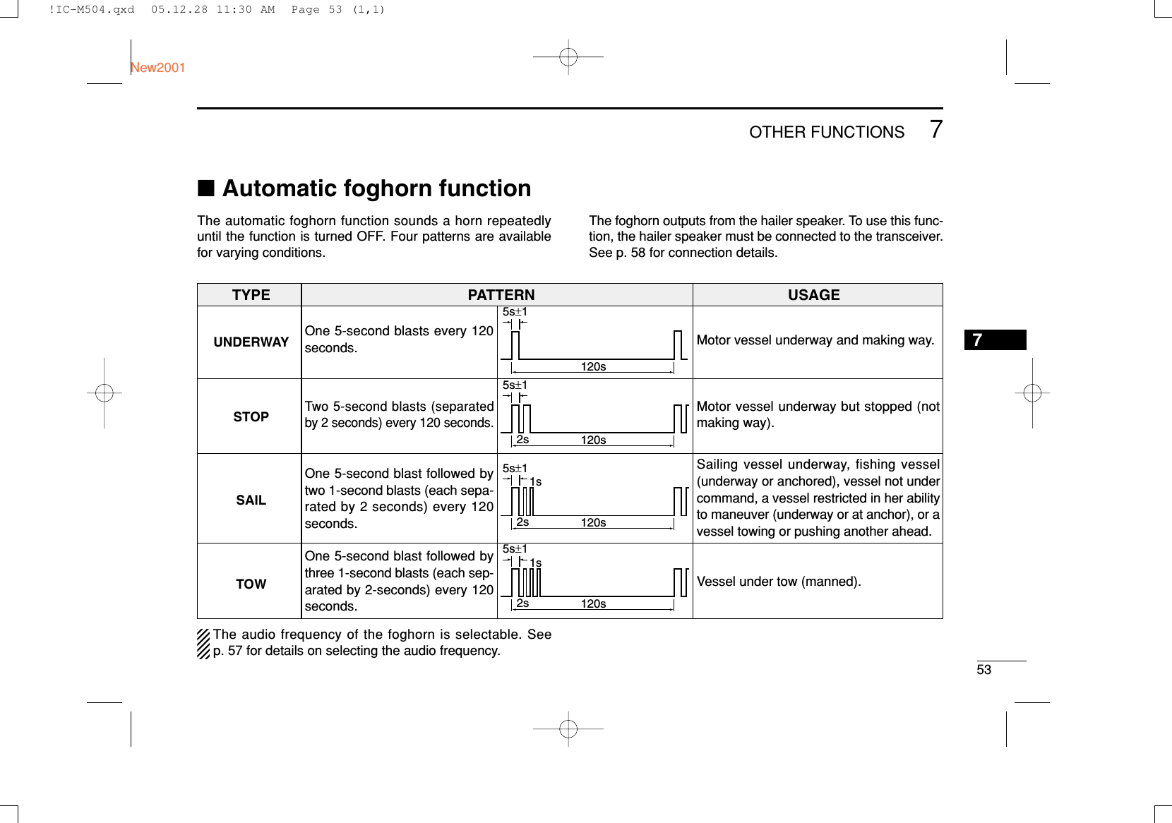
![547OTHER FUNCTIONSNew2001qWhile pushing and holding [H/L], push [HAIL•RX ] toenter auto foghorn mode.wRotate [DIAL] to select the desired foghorn pattern, push[DIAL•ENTER].•‘UUNNDDEERRWWAAYY,’ ‘SSTTOOPP,’ ‘SSAAIILL,’ ‘TTOOWW’ are available. (p. 53)• Even if [DIAL•ENTER] hasn’t been pushed, the display auto-matically changes to the next step after 2 sec. of inactivity.eRotate [DIAL] to adjust the foghorn level, push[DIAL•ENTER].• The foghorn level is adjustable in 30 steps.• Even if [ENT] hasn’t been pushed, the display automaticallychanges to the next step after 2 sec. of inactivity.rTo return to normal operation, repeat step q.When a DSC call is received, the automatic foghorn func-tion is interrupted with an automatic return to the trans-ceiver mode. The transceiver’s display indicates ‘Receiv-ing DSC calls.’ (p. 41)25W25W INTINTTAGTAGFOGHORNFOGHORN1515<ENT<ENT˘OK>OK> CALLINGCALLINGRotatePush25W25W INTINTTAGTAGFOGHORNFOGHORN1515UNDERWAYUNDERWAY CALLINGCALLINGThe selected foghorn pattern is displayed.25W25W INTINTTAGTAG˘UNDERWAYUNDERWAYSTOPSTOP<ENT<ENT˘OK>OK> CALLINGCALLINGPush and!IC-M504.qxd 05.12.28 11:30 AM Page 54 (1,1)](https://usermanual.wiki/ICOM-orporated/291400/User-Guide-634763-Page-60.png)
![558SET MODE78■Set mode programmingSet mode is used to change the conditions of the transceiver’sfunctions: Scan type, Scan resume timer, Weather alert,Dual/Tri-watch, Beep tone, LCD contrast, Automatic foghorn fre-quency, Radio power, Scrambler type* and Scrambler code.**Appears only when the optional scrambler unit is installed.Available functions may differ depending on dealer setting.qTurn power OFF.wWhile pushing and holding [16•9], turn power ON to enterSet mode.eAfter the display appears, release [16•9].rRotate [DIAL] to select the desired item, push[DIAL•ENTER].tRotate [DIAL] to select the desired condition of the item.yPush [CLR], or rotate [DIAL] to select “EExxiitt,” then push[DIAL•ENTER] to exit set mode and returns to normal op-eration condition.■Set mode itemsDScan typeThe transceiver has 2 scan types: Normal scan and Priorityscan. Normal scan searches all TAG channels in the selectedchannel group. Priority scan searches all TAG channels in se-quence while monitoring Channel 16.DDScan resume timerThe scan resume timer can be selected as a pause (OFF) ortimer scan (ON). When OFF is selected, the scan pausesuntil the signal disappears. When ON is selected, the scanpauses 5 sec. and resumes even if a signal has been re-ceived on any other channel than Channel 16.--Set Mode--Scan TimerON˘OFF<ENT˘OK>Default: OFF--Set Mode--Scan-TypePriority˘Normal<ENT˘OK>Default: NormalRotate--Set Mode--˘Scan TypeScan TimerWX AlertDual/TriBeepContrastFoghorn FrequencyRadio PowerScrambler TypeScrambler CodeExit•SET MODE CONSTRUCTION!IC-M504.qxd 05.12.28 11:30 AM Page 55 (1,1)](https://usermanual.wiki/ICOM-orporated/291400/User-Guide-634763-Page-61.png)
![578SET MODENew20018DDAutomatic foghorn frequencyThe audio frequency of the automatic foghorn can be ad-justed to suit your preference. While this item is selected,pushing [PTT] outputs the foghorn— experiment with the fre-quencies available until you find one you like.• Available frequency range is 200 Hz to 850Hz in 50 Hz step.DDRadio powerThis item sets the Radio Power function ON or OFF.ON : The transceiver’s power is controlled by the optionalcommand microphone. When the command micro-phone is turned OFF, the transceiver will also be turnedOFF automatically.OFF : The transceiver’s power is not controlled by the optionalcommand microphone. Even if the command microphoneis turned OFF, the transceiver will continue to work.DDScrambler type (Appears when a scrambler unit is installed)When an optional scrambler unit is installed, the scramblertype can be selected in set mode depending on dealer setting.DDScrambler code (Appears when a scrambler unit is installed)When an optional scrambler unit is installed, the scramblercode can be set depending on dealer setting.When the UT-112 is installed, 32 codes (1 to 32) can be se-lected.When the UT-98 is installed, 128 codes (0 to 127) can be se-lected.--Set Mode--Scrambler Code5432˘1<ENT˘OK>--Set Mode--Scrambler Code4321˘0<ENT˘OK>Default: 0(When UT-98 is installed)Default: 1(When UT-112 is installed)--Set Mode--Scrambler TypeUT-98˘UT-112<ENT˘OK>Default: UT-112--Set Mode--Radio Power˘ONOFF<ENT˘OK>Default: ON--Set Mode--FoghornFoghorn FrequencyFrequency˘400350300250200<ENT˘OK>Default: 400!IC-M504.qxd 05.12.28 11:30 AM Page 57 (1,1)](https://usermanual.wiki/ICOM-orporated/291400/User-Guide-634763-Page-63.png)
![6710TROUBLESHOOTING910PROBLEM POSSIBLE CAUSE SOLUTION REF.No sound from speaker. • Squelch level is too high.• Volume level is too low.• Speaker has been exposed to water.p. 8p. 8—• Set [SQL] to the threshold point.• Set [VOL] to a suitable level.• Drain water from the speaker.The transceiver doesnot turn ON.• Bad connection to the power supply. p. 58• Check the connection to the transceiver.Transmitting is impossi-ble, or high power cannot be selected.• Some channels are for low power or re-ceive only.• The output power is set to low.pgs. 6,7, 70p. 8• Change channels.• Push [H/L] to select high power.Scan does not start. • TAG channel is not programmed. • Set the desired channels as TAG channels. p. 13No beeps. • Beep tones are turned OFF.• The squelch is open.• Turn the beep tone ON in Set mode.• Set [SQL] to the threshold point.p. 56p. 8Distress call cannot betransmitted.• MMSI (DSC self ID) code is not pro-grammed.• Program the MMSI (DSC self ID) code. p. 15Sensitivity is low. • The Attenuator is activated. • Push [LO/DX•IC•SCRM] to turn the functionOFF.p. 8!IC-M504.qxd 05.12.28 11:30 AM Page 67 (1,1)](https://usermanual.wiki/ICOM-orporated/291400/User-Guide-634763-Page-73.png)