ICOM orporated 291400 VHF-FM Marine Transceiver User Manual Manual
ICOM Incorporated VHF-FM Marine Transceiver Manual
Manual
INSTRUCTION MANUAL
New2001
iM504
VHF MARINE TRANSCEIVER
!IC-M504.qxd 05.12.28 11:29 AM Page A (1,1)
i
New2001
FOREWORD
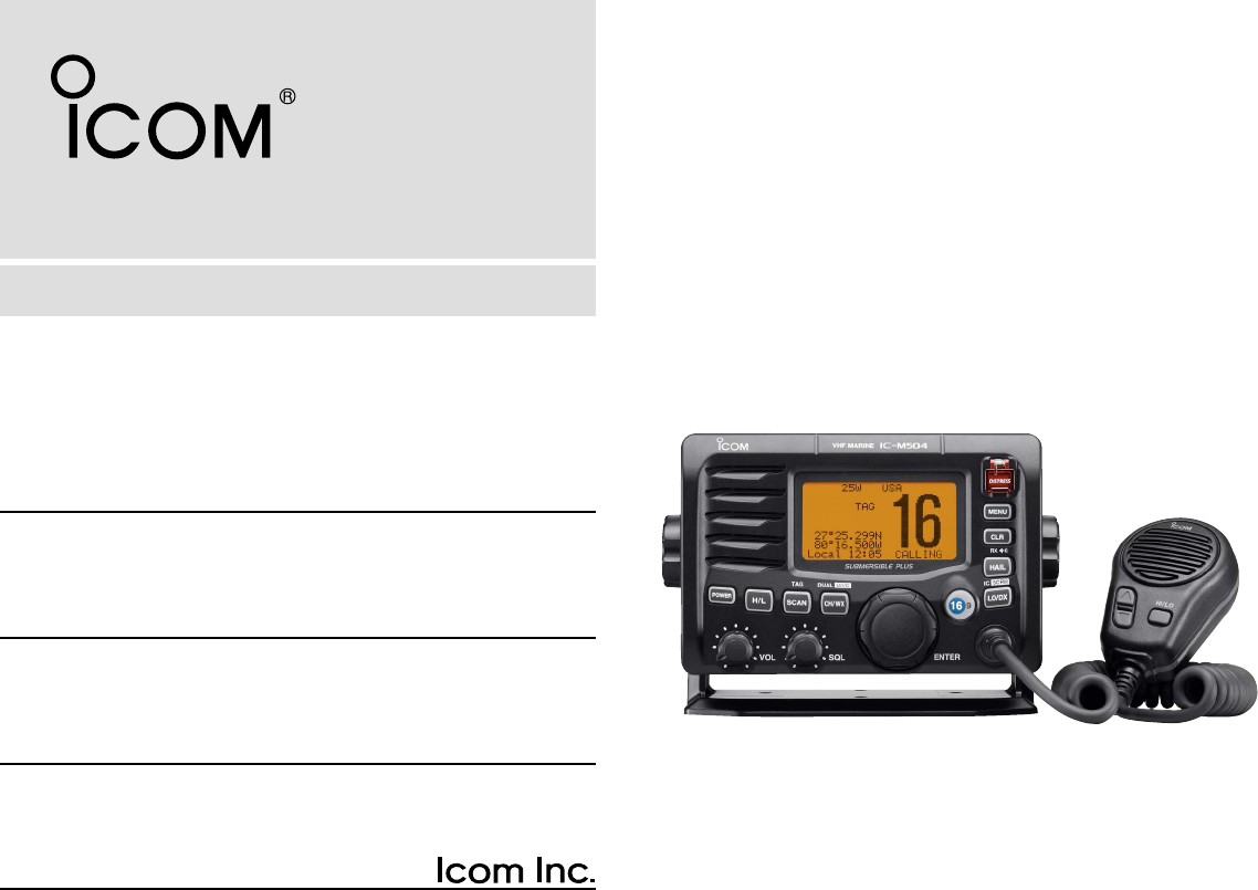
Thank you for purchasing this Icom product. The IC-M504
VHF MARINE TRANSCEIVER
is designed and built with Icom’s
state of the art technology and craftsmanship. With proper
care, this product should provide you with years of trouble-
free operation.
We want to take a couple of moments of your time to thank
you for making the IC-M504 your radio of choice, and hope
you agree with Icom’s philosophy of “technology first.” Many
hours of research and development went into the design of
your IC-M504.
D
FEATURES
❍Simple operation with large keys
❍Easy to hear speaker
❍Built-in DSC meets ITU Class D requirement
❍Rugged waterproof construction
❍Optional COMMANDMIC (HM-157/HM-162) are
available
IMPORTANT
READ ALL INSTRUCTIONS carefully and completely
before using the transceiver.
SAVE THIS INSTRUCTION MANUAL — This in-
struction manual contains important operating instructions for
the IC-M504.
EXPLICIT DEFINITIONS
WORD DEFINITION
RWARNING!
CAUTION
NOTE
Personal injury, fire hazard or electric shock
may occur.
Equipment damage may occur.
Recommended for optimum use. No risk of
personal injury, fire or electric shock.
CLEAN THE TRANSCEIVER AND MICROPHONE THOR-
OUGHLY WITH FRESH WATER after exposure to water
including salt water, otherwise, the keys and switch may
become inoperable due to salt crystallization.
Icom, Icom Inc. and the logo are registered trademarks of Icom Incor-
porated (Japan) in the United States, the United Kingdom, Germany, France,
Spain, Russia and/or other countries.
COMMANDMIC II and COMMANDMIC III is a trademark of Icom Incorporated
(Japan) in the United States.
!IC-M504.qxd 05.12.28 11:29 AM Page i (1,1)

ii
IN CASE OF EMERGENCY
If your vessel requires assistance, contact other vessels and
the Coast Guard by sending a Distress call on Channel 16.
Or, transmit your Distress call using digital selective calling
on Channel 70.
NOTE
A WARNING STICKER is supplied with the transceiver.
To comply with FCC regulations, this sticker must be affixed in
such a location as to be readily seen from the operating con-
trols of the radio as in the diagram below. Make sure the cho-
sen location is clean and dry before applying the sticker.
EXAMPLE
USING DIGITAL SELECTIVE CALLING (Ch 70)
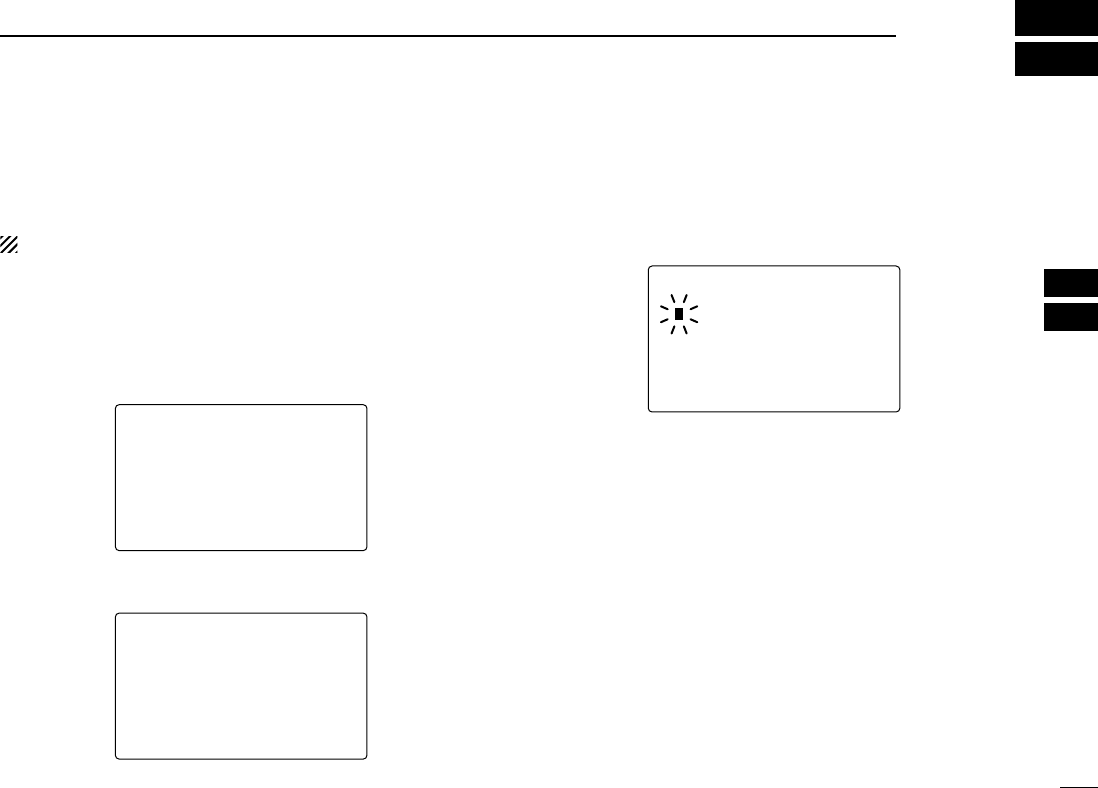
DISTRESS CALL PROCEDURE
1. While lifting up the key cover, push and hold
[DISTRESS] for 5 sec. until you hear 5 short beeps
change to one long beep.
2. Wait for an acknowledgment on Channel 70 from a coast
station.
• After the acknowledgement is received, Channel 16 is auto-
matically selected.
3. Push and hold [PTT], then transmit the appropriate
information as listed above.
USING CHANNEL 16
DISTRESS CALL PROCEDURE
1. “MAYDAY MAYDAY MAYDAY.”
2. “THIS IS ...............” (name of vessel).
3. Say your call sign or other indication of the vessel (AND
9-digit DSC ID if you have one).
4. “LOCATED AT ...............” (your position).
5. State the nature of the distress and assistance required.
6. Give any other information which might facilitate the
rescue.
New2001
!IC-M504.qxd 05.12.28 11:29 AM Page ii (1,1)

iii
New2001
RADIO OPERATOR WARNING
Icom requires the radio operator to meet the
FCC Requirements for Radio Frequency Expo-
sure. An omnidirectional antenna with gain not
greater than 9 dBi must be mounted a minimum
of 5 meters (measured from the lowest point of
the antenna) vertically above the main deck and
all possible personnel. This is the minimum safe separation
distance estimated to meet all RF exposure compliance re-
quirements. This 5 meter distance is based on the FCC Safe
Maximum Permissible Exposure (MPE) distance of 3 meters
added to the height of an adult (2 meters) and is appropriate
for all vessels.
For watercraft without suitable structures, the antenna must
be mounted so as to maintain a minimum of 1 meter vertically
between the antenna, (measured from the lowest point of the
antenna), to the heads of all persons AND all persons must
stay outside of the 3 meter MPE radius.
Do not transmit with radio and antenna when persons are
within the MPE radius of the antenna, unless such persons
(such as driver or radio operator) are shielded from antenna
field by a grounded metallic barrier. The MPE Radius is the
minimum distance from the antenna axis that person should
maintain in order to avoid RF exposure higher than the allow-
able MPE level set by FCC.
WARNING
FAILURE TO OBSERVE THESE LIMITS MAY ALLOW
THOSE WITHIN THE MPE RADIUS TO EXPERIENCE RF
RADIATION ABSORPTION WHICH EXCEEDS THE FCC
MAXIMUM PERMISSIBLE EXPOSURE (MPE) LIMIT.
IT IS THE RESPONSIBILITY OF THE RADIO OPERATOR
TO ENSURE THAT THE MAXIMUM PERMISSIBLE EXPO-
SURE LIMITS ARE OBSERVED AT ALL TIMES DURING
RADIO TRANSMISSION. THE RADIO OPERATOR IS TO
ENSURE THAT NO BYSTANDERS COME WITHIN THE
RADIUS OF THE MAXIMUM PERMISSIBLE EXPOSURE
LIMITS.
Determining MPE Radius
THE MAXIMUM PERMISSIBLE EXPOSURE (MPE) RA-
DIUS HAS BEEN ESTIMATED TO BE A RADIUS OF
ABOUT 3M PER OET BULLETIN 65 OF THE FCC.
THIS ESTIMATE IS MADE ASSUMING THE MAXIMUM
POWER OF THE RADIO AND ANTENNAS WITH A MAXI-
MUM GAIN OF 9dBi ARE USED FOR A SHIP MOUNTED
SYSTEM.
!IC-M504.qxd 05.12.28 11:29 AM Page iii (1,1)

iv
New2001
FOREWORD …………………………………………………………… i
IMPORTANT …………………………………………………………… i
EXPLICIT DEFINITIONS ……………………………………………… i
IN CASE OF EMERGENCY…………………………………………… ii
NOTE …………………………………………………………………… ii
RADIO OPERATOR WARNING ……………………………………… iii
TABLE OF CONTENTS ……………………………………………… iv
PRECAUTIONS ………………………………………………………… v
1 OPERATING RULES ……………………………………………… 1
2 PANEL DESCRIPTION ………………………………………… 2–5
■Front panel ……………………………………………………… 2
■Function display ………………………………………………… 4
■Microphone ……………………………………………………… 5
3 BASIC OPERATION…………………………………………… 6–11
■Channel selection ……………………………………………… 6
■Receiving and transmitting……………………………………… 8
■Call channel programming ……………………………………… 9
■Channel comments …………………………………………… 10
■Microphone Lock function …………………………………… 10
■Display backlight ……………………………………………… 10
■Optional voice scrambler operation ………………………… 11
4 SCAN OPERATION ………………………………………… 12–13
■Scan types ……………………………………………………… 12
■Setting TAG channels ………………………………………… 13
■Starting a scan ………………………………………………… 13
5 DUALWATCH/TRI-WATCH ……………………………………… 14
■Description ……………………………………………………… 14
■Operation ……………………………………………………… 14
6 DSC OPERATION …………………………………………… 15–49
■MMSI code programming……………………………………… 15
■MMSI code check ……………………………………………… 16
■DSC address ID………………………………………………… 17
■Position and time programming ……………………………… 21
■Position and time indication …………………………………… 22
■Distress call …………………………………………………… 23
■Transmitting DSC calls ………………………………………… 26
■Receiving DSC calls …………………………………………… 41
■Received messages …………………………………………… 45
■DSC Set mode ………………………………………………… 47
7 OTHER FUNCTIONS………………………………………… 50–54
■Intercom operation …………………………………………… 50
■RX Speaker function …………………………………………… 51
■Hailer operation ………………………………………………… 52
■Automatic foghorn function …………………………………… 53
8 SET MODE …………………………………………………… 55–57
■Set mode programming ……………………………………… 55
■Set mode items ………………………………………………… 55
9 CONNECTIONS AND MAINTENANCE …………………… 58–64
■Connections …………………………………………………… 58
■Supplied accessories ………………………………………… 59
■Antenna ………………………………………………………… 59
■Fuse replacement ……………………………………………… 59
■Mounting the transceiver ……………………………………… 60
■MB-75 installation ……………………………………………… 61
■UT-98/UT-112 installation ……………………………………… 62
■HM-157/HM-162 installation ………………………………… 63
10 TROUBLESHOOTING …………………………………………… 67
11 SPECIFICATIONS AND OPTIONS …………………………… 68
■Specifications …………………………………………………… 68
■Options ………………………………………………………… 69
12 CHANNEL LIST ………………………………………………… 70
TEMPLATE
TABLE OF CONTENTS 1
2
3
4
5
6
7
8
9
10
11
12
!IC-M504.qxd 05.12.28 11:29 AM Page iv (1,1)

v
New2001
PRECAUTIONS
RWARNING! NEVER connect the transceiver to an AC
outlet. This may pose a fire hazard or result in an electric
shock.
CAUTION: Changes or modifications to this device, not ex-
pressly approved by Icom Inc., could void your authority to
operate this device under FCC regulations.
NEVER connect the transceiver to a power source of more
than 16 V DC or use reverse polarity. This will ruin the trans-
ceiver.
NEVER cut the DC power cable between the DC plug at the
back of the transceiver and fuse holder. If an incorrect con-
nection is made after cutting, the transceiver may be dam-
aged.
NEVER place the transceiver where normal operation of the
vessel may be hindered or where it could cause bodily injury.
KEEP the transceiver at least 3.3 ft (1 m) away from the
ship’s navigation compass.
DO NOT use or place the transceiver in areas with temper-
atures below –4°F (–20°C) or above +140°F (+60°C) or, in
areas subject to direct sunlight, such as the dashboard.
AVOID the use of chemical agents such as benzine or al-
cohol when cleaning, as they may damage the transceiver
surfaces. If the transceiver becomes dusty or dirty, wipe it
clean with a soft, dry cloth.
BE CAREFUL! The transceiver rear panel will become
hot when operating continuously for long periods.
Place the transceiver in a secure place to avoid inadvertent
use by children.
BE CAREFUL! The transceiver and optional HM-162
COMMANDMIC III
™/HM-157
COMMANDMIC II
™ employ water-
proof construction, which corresponds to IPX8 of the interna-
tional standard IEC 60529 (2001). However, once the trans-
ceiver or microphone has been dropped, waterproofing
cannot be guaranteed due to the fact that the case may be
cracked, or the waterproof seal damaged, etc.
!IC-M504.qxd 05.12.28 11:29 AM Page v (1,1)

1
1
OPERATING RULES
DDPRIORITIES
• Read all rules and regulations pertaining to priorities and
keep an up-to-date copy handy. Safety and Distress calls
take priority over all others.
• You must monitor Channel 16 when you are not operating
on another channel.
• False or fraudulent distress signals are prohibited and pun-
ishable by law.
DDPRIVACY
• Information overheard but not intended for you cannot law-
fully be used in any way.
• Indecent or profane language is prohibited.
DDRADIO LICENSES
(1) SHIP STATION LICENSE
You must have a current radio station license before using the
transceiver. It is unlawful to operate a ship station which is not
licensed.
Inquire through your dealer or the appropriate government
agency for a Ship-Radiotelephone license application. This
government-issued license states the call sign which is your
craft’s identification for radio purposes.
(2) OPERATOR’S LICENSE
A Restricted Radiotelephone Operator Permit is the license
most often held by small vessel radio operators when a radio
is not required for safety purposes.
The Restricted Radiotelephone Operator Permit must be
posted or kept with the operator. Only a licensed radio opera-
tor may operate a transceiver.
However, non-licensed individuals may talk over a transceiver
if a licensed operator starts, supervises, ends the call and
makes the necessary log entries.
Keep a copy of the current government rules and regulations
handy.
Radio license for boaters (U.S.A. only)
The Telecommunications Act of 1996 permits recreational
boaters to have and use a VHF marine radio, EPIRB, and
marine radar without having an FCC ship station license.
Boaters traveling on international voyages, having an HF
single sideband radiotelephone or marine satellite termi-
nal, or required to carry a marine radio under any other
regulation must still carry an FCC ship station license. For
further information, see the FCC Ship Radio Stations Fact
Sheet.
1
!IC-M504.qxd 05.12.28 11:29 AM Page 1 (1,1)
2
PANEL DESCRIPTION
New2001
2
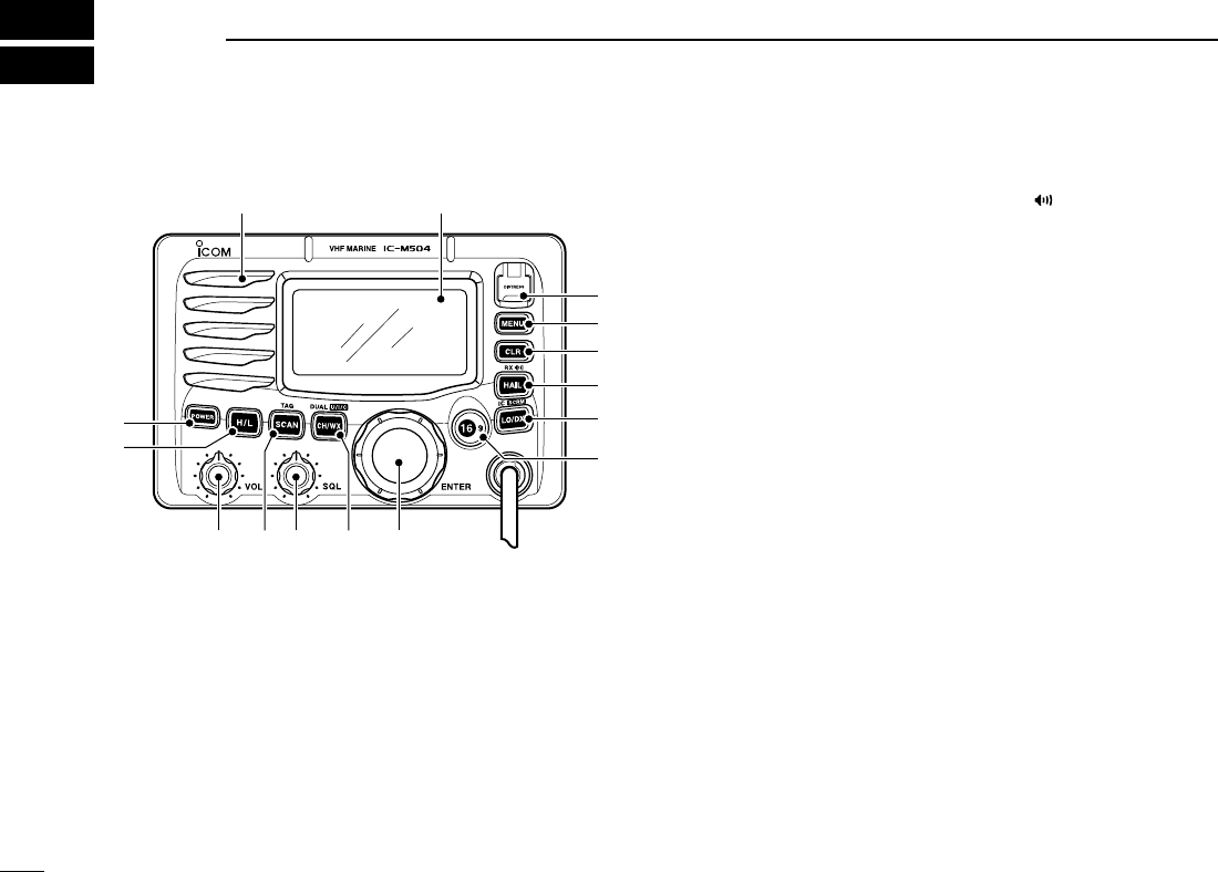
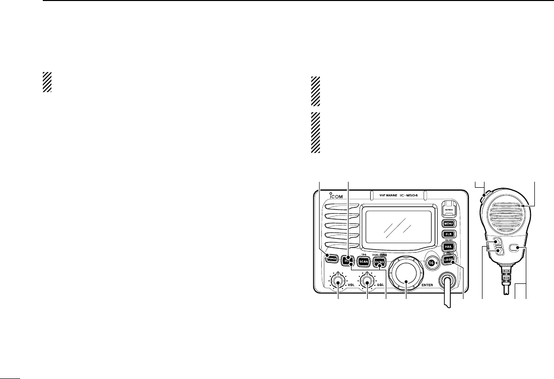
■Front panel
qDISTRESS KEY [DISTRESS]
Push for 5 sec. to transmit a Distress call. (p. 23)
wDSC MENU KEY [MENU]
Push to toggle the DSC menu appear or disappear. (p. 15)
eCLEAR KEY [CLR]
Push to cancel the entered function, exit Set mode. (p. 55)
rHAIL/RX SPEAKER KEY [HAIL•RX ]
➥Push to turn the hailer mode ON or OFF. (p. 52)
➥Push and hold for 1 sec. to turn the RX Speaker mode
ON or OFF. (p. 51)
➥While pushing and holding [H/L], push to turn the auto
foghorn function ON. (p. 54)
tATTENUATOR/INTERCOM KEY [LO/DX•IC•SCRM]
➥Push to turn the Attenuator function ON or OFF. (p. 8)
•“
LLOOCC” appears when the Attenuator function is turned ON.
➥Push and hold for 1 sec. to activate an optional Inter-
com function. (p. 50)
➥Push and hold to calls the optional command micro-
phone while in Intercom mode. (p. 50)
➥While pushing and holding [H/L], push to turn the voice
scrambler function ON or OFF. (p. 11)
yCHANNEL 16/CALL CHANNEL KEY [16•9]
➥Push to select Channel 16. (p. 6)
➥Push and hold for 1 sec. to select Call channel. (p. 6)
•“
CCAALLLL” appears when Call channel is selected.
➥Push and hold for 3 sec. to enter Call channel program-
ming condition when Call channel is selected. (p. 9)
➥While pushing and holding [H/L], push to enter the
channel comment programming condition. (p. 10)
➥Advance the cursor while in the channel comment pro-
gramming condition. (p. 10)
➥While turning power ON, push to enter Set mode.
(p. 55)
Function display (p. 4)Speaker
q
e
r
t
y
w
uio!0!1
!2
!3
!IC-M504.qxd 05.12.28 11:29 AM Page 2 (1,1)

3
2
PANEL DESCRIPTION
New2001
uCHANNEL SELECTOR [DIAL•ENTER]
➥Rotate to select the operating channels, Set mode set-
tings, etc. (pgs. 6, 7, 55)
➥While pushing and holding [H/L], rotate to adjust the
brightness of the LCD and key backlight. (p. 10)
➥Push to enter the input channel comment, selected
item, etc. (pgs. 10, 55)
➥Rotate to check TAG channels, changes scanning di-
rection or resumes the scan manually during scan.
(p. 13)
➥While pushing and holding [PA•RX ], rotate to adjust
the audio level in RX Speaker mode. (p. 51)
iCHANNEL/WEATHER CHANNEL KEY
[CH/WX•DUAL•U/I/C]
➥Selects and toggles the regular channel and Weather
channel when pushed momentarily. (p. 7)
➥Push and hold for 1 sec. to start Dualwatch or Tri-watch.
(p. 14)
➥Push to stop Dualwatch or Tri-watch when either is acti-
vated. (p. 14)
➥Move the cursor backward while in the channel com-
ment programming condition. (p. 10)
➥While pushing and holding [H/L], push to select one of
three channel groups in sequence. (p. 7)
• U.S.A., International and Canadian channels are available.
oSQUELCH CONTROL [SQL]
Rotate to set the squelch threshold level. (p. 8)
!0 SCAN KEY [SCAN•TAG] (p. 13)
➥Push to start and stop Normal or Priority scan.
➥Push and hold for 1 sec. to set or clear the displayed
channel as a TAG (scanned) channel.
➥While pushing and holding [H/L], push for 3 sec. to
clear or set all TAG channels in the selected channel
group.
!1 VOLUME CONTROL [VOL] (p. 8)
Rotate to adjust the audio level.
!2 TRANSMIT POWER KEY [H/L]
➥Push to toggle the power high or low. (p. 8)
• Some channels are set to low power only.
➥While pushing this key, some keys perform secondary
functions.
!3 POWER KEY [POWER] (p. 8)
➥Push to turn power ON.
➥Push and hold for 1 sec. to turn power OFF.
2
!IC-M504.qxd 05.12.28 11:29 AM Page 3 (1,1)

4
2PANEL DESCRIPTION
New2001
■Function display
qRX SPEAKER INDICATOR (p. 51)
Appears during the RX Speaker mode.
wPOWER INDICATOR (p. 8)
➥“2255WW” appears when high power is selected.
➥“11WW” appears when low power is selected.
eTAG CHANNEL INDICATOR (p. 13)
Appears when a TAG channel is selected.
rDUPLEX INDICATOR (p. 7)
Appears when a duplex channel is selected.
tCHANNEL GROUP INDICATOR (p. 7)
Indicates whether an U.S.A. “UUSSAA,” International “IINNTT,”
Canadian “CCAANN” or weather “WWXX” channel is in use.
yCALL CHANNEL INDICATOR (p. 9)
Appears when the call channel is selected.
uCHANNEL NUMBER READOUT
➥Indicates the selected operating channel number.
• “ ” appears when a simplex channel is selected. (p. 7)
iCHANNEL COMMENT INDICATOR
Channel comment appears if programmed. (p. 10)
oTIME ZONE INDICATOR
➥Shows the current time data when a GPS receiver is
connected.
•“
????” may blink every 2 sec. instead of current time data when
the GPS current time data is invalid.
•“
????” may blink every 2 sec. instead of current time data 4
hours after the time data is input manually, up until 23.5 hours
have past.
➥“LLooccaall” appears when the offset time data is set.
(p. 47)
➥“NNoo TTiimmee” appears when no GPS receiver is con-
nected and no time data is input manually.
BUSY 25W INT CALL
LOC RX DUP
SCRM TAG
NORMAL SCAN
-34°34.506N
123°23.236W
Local 1:10 CALLING
qwert y
!4
!3
!2
!0
o
!1 u
i
!IC-M504.qxd 05.12.28 11:29 AM Page 4 (1,1)
5
2
PANEL DESCRIPTION
New2001
2
!0 POSITION INDICATOR
➥Shows the GPS position data.
•“
????” may blink every 2 sec. instead of position data when the
GPS position data is invalid. In such a case, the last position
data is held for up to 23.5 hours.
•“
????” may blink every 2 sec. instead of position data 4 hours
after the position data is input manually, up until 23.5 hours
have past.
➥“NNoo PPoossiittiioonn” appears when no GPS receiver is
connected and no position data is input manually.
!1 SCAN INDICATOR
➥“PPRRII--SSCCAANN 1166” appears during Priority scan;
“NNOORRMMAALL SSCCAANN” appears during Normal scan. (p. 13)
➥“DDUUAALL 1166” appears during Dualwatch; “TTRRII 1166” ap-
pears during Tri-watch. (p. 14)
!2 SCRAMBLER INDICATOR (p. 11)
Appears when the voice scrambler function is activated.
(only when the optional scrambler unit is installed.)
!3 LOCAL INDICATOR (p. 8)
Appears when the Attenuator function is turned ON.
!4 BUSY/TRANSMIT INDICATOR (p. 8)
➥“BBUUSSYY” appears when receiving a signal or when the
squelch opens.
➥“TTXX” appears while transmitting.
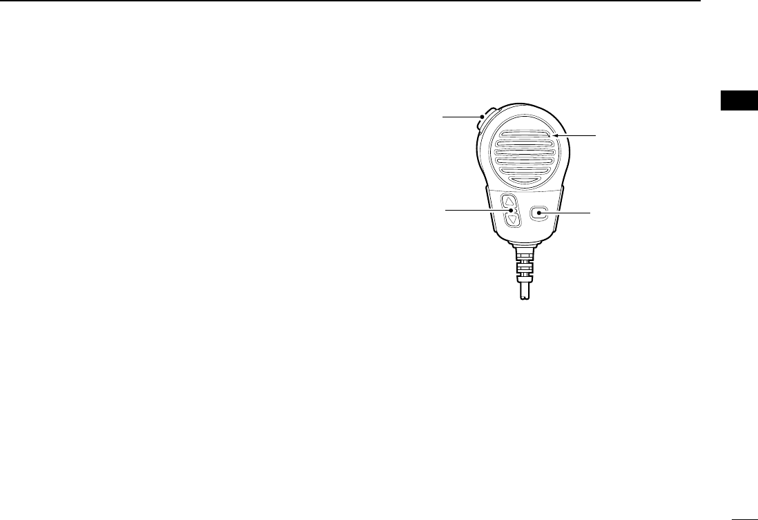
■Microphone
qPTT SWITCH [PTT]
Push and hold to transmit; release to receive. (p. 8)
wCHANNEL UP/DOWN KEYS [YY]/[ZZ]
➥Push either key to change the operating memory chan-
nel, Set mode settings, etc. (pgs. 6, 7, 55)
➥Checks TAG channels, changes scanning direction or
resumes the scan manually during scan. (p. 13)
eTRANSMIT POWER KEY [HI/LO]
➥Toggles power high and low when pushed. (p. 8)
• Some channels are set to low power only.
➥While pushing and holding [HI/LO], turn power ON to
toggle the Microphone Lock function ON and OFF.
(p. 10)
Microphone
w
q
e
!IC-M504.qxd 05.12.28 11:29 AM Page 5 (1,1)

6
BASIC OPERATION
New2001
3
■Channel selection
ïïChannel 16
Channel 16 is the distress and safety channel. It is used for
establishing initial contact with another station and for emer-
gency communications. Channel 16 is monitored during both
Dualwatch and Tri-watch. While standing by, you must moni-
tor Channel 16.
➥Push [16•9] momentarily to select Channel 16.
➥Push [CH/WX•DUAL•U/I/C] to return to the condition before
selecting Channel 16, or rotate [DIAL] to select an operating
channel.
ïïChannel 9 (Call channel)
Each regular channel group has a separate leisure-use call
channel. The call channel is monitored during Tri-watch. The
call channels can be programmed (p. 9) and are used to store
your most often used channel in each channel group for quick
recall.
➥Push [16•9] for 1 sec. to select the call channel of the se-
lected channel group.
•“
CCAALLLL” and call channel number appear.
• Each channel group may have an independent call channel after
programming a call channel. (p. 9)
➥Push [CH/WX•DUAL•U/I/C] to return to the condition be-
fore selecting call channel, or rotate [DIAL] to select an op-
erating channel.
25W25W INTINT CALLCALL
TAGTAG
3434°34.506N34.506N
123123°23.236W23.236W
UTCUTC 1212:00:00 CALLINGCALLING
Push
for 1 sec.
25W INT
TAG
34°34.506N
123°23.236W
UTC 12:00 CALLING
Push
!IC-M504.qxd 05.12.28 11:29 AM Page 6 (1,1)
7
3
BASIC OPERATION
New2001
3
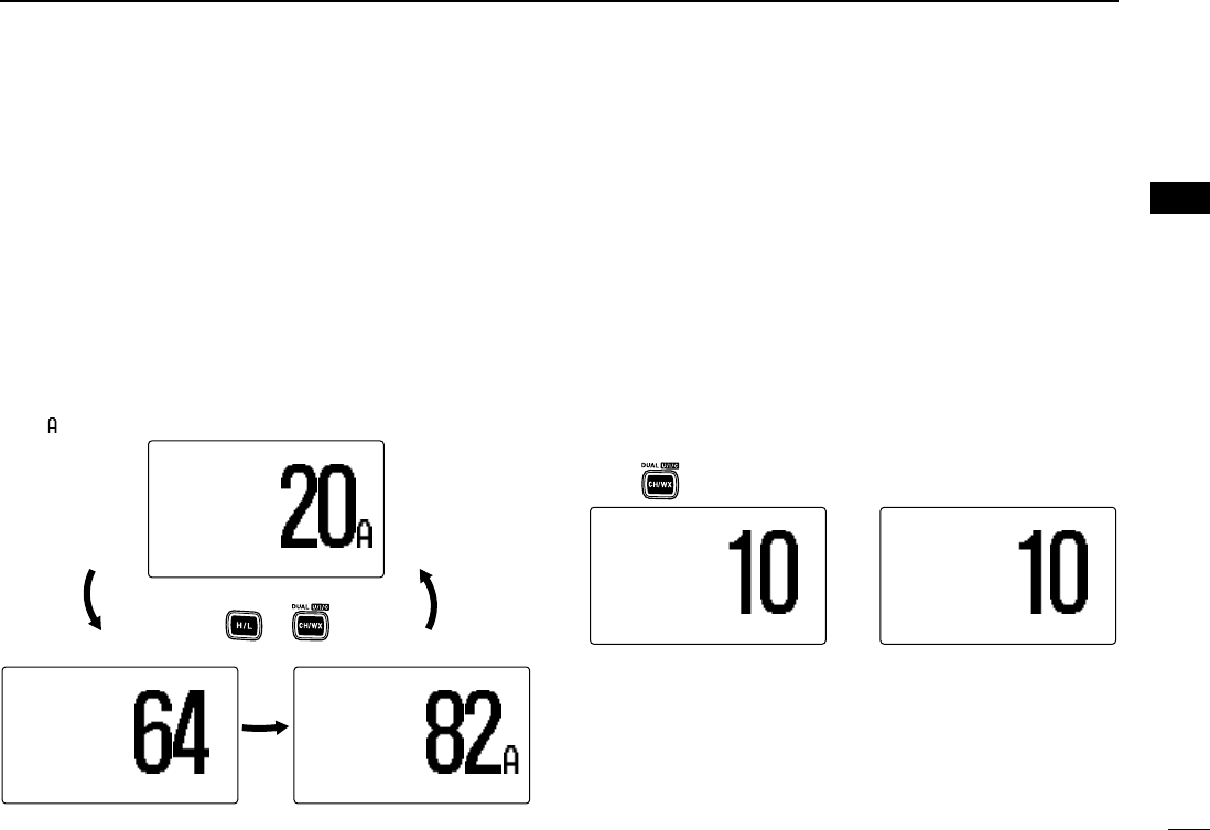
ïïU.S.A., international and Canadian channels
The IC-M504 is pre-programmed with 57 U.S.A., 57 interna-
tional and 61 Canadian channels. These channel groups may
be specified for the operating area.
qPush [CH/WX•DUAL•U/I/C] to select a regular channel.
• If a weather channel appears, push [CH/WX•DUAL•U/I/C] again.
wWhile pushing and holding [H/L], push [CH/WX•DUAL•
U/I/C] to change the channel group, if necessary.
• U.S.A., International and Canadian channel groups can be se-
lected in sequence.
eRotate [DIAL] to select a channel.
•“
DDUUPP” appears for duplex channels.
• “ ” appears when a simplex channel is selected.
ïïWeather channels
The IC-M504 has 10 weather channels. These are used for
monitoring broadcasts from NOAA (National Oceanographic
and Atmospheric Administration.)
The transceiver can detect a weather alert tone on the se-
lected weather channel while receiving the channel, during
standby on a regular channel or while scanning. (p. 56)
qPush [CH/WX•DUAL•U/I/C] once or twice to select a
weather channel.
•“
WWXX” appears when a weather channel is selected.
• “WWXX AALLEERRTT” appears when the Weather Alert function is in
use. (p. 56)
wRotate [DIAL] to select a channel.
WXWX ALERTALERT
3434°34.506N34.506N
123123°23.236W23.236W
UTCUTC 1212:00:00163163.275MHz.275MHz
WXWX
3434°34.506N34.506N
123123°23.236W23.236W
UTCUTC 1212:00:00163163.275MHz.275MHz
Push once or twice
When weather alert is OFF. When weather alert is ON.
25W25W USAUSA
3434°34.506N34.506N
123123°23.236W23.236W
UTCUTC 1212:00:00 PORTPORT OPROPR
25W25W INTINT
DUPDUP
3434°34.506N34.506N
123123°23.236W23.236W
UTCUTC 1212:00:00 TELEPHONETELEPHONE
25W25W CANCAN
3434°34.506N34.506N
123123°23.236W23.236W
UTCUTC 1212:00:00 CCGCCG
Push +
!IC-M504.qxd 05.12.28 11:29 AM Page 7 (1,1)
8
3BASIC OPERATION
New2001
■Receiving and transmitting
CAUTION: Transmitting without an antenna may dam-
age the transceiver.
qPush [POWER] to turn power ON.
wSet the audio and squelch levels.
➥Rotate [SQL] fully counterclockwise in advance.
➥Rotate [VOL] to adjust the audio output level.
➥Rotate [SQL] clockwise until the noise disappears.
eWhile pushing and holding [H/L], push [CH/WX•DUAL•
U/I/C] to change the channel group. (p. 7)
rRotate [DIAL] to select the desired channel. (pgs. 6, 7)
• When receiving a signal, “BBUUSSYY” appears and audio is emitted
from the speaker.
• Further adjustment of [VOL] may be necessary.
tPush [LO/DX•IC•SCRM] to turn the receive Attenuator
function ON or OFF, if necessary.
•“
LLOOCC” appears when the receive Attenuator function is in use.
yPush [H/L] to select the output power if necessary.
•“
2255WW” or “11WW” appears when high or low power is selected, re-
spectively.
• Choose low power for short range communications, choose high
power for longer distance communications.
• Some channels are for low power only.
uPush and hold [PTT] to transmit, then speak into the mi-
crophone.
•“
TTXX” appears.
• Channel 70 cannot be used for transmission other than DSC.
iRelease [PTT] to receive.
Simplex channels, 3, 21, 23, 61, 64, 81, 82 and 83 CAN-
NOT be lawfully used by the general public in U.S.A. wa-
ters.
IMPORTANT: To maximize the readability of your trans-
mitted signal, pause a few sec. after pushing [PTT], hold
the microphone 2 to 4 inches (5 to 10 cm) from your mouth
and speak into the microphone at a normal voice level.
t
Microphone
qy
reww
iu
rey
!IC-M504.qxd 05.12.28 11:29 AM Page 8 (1,1)
9
3
BASIC OPERATION
New2001
3
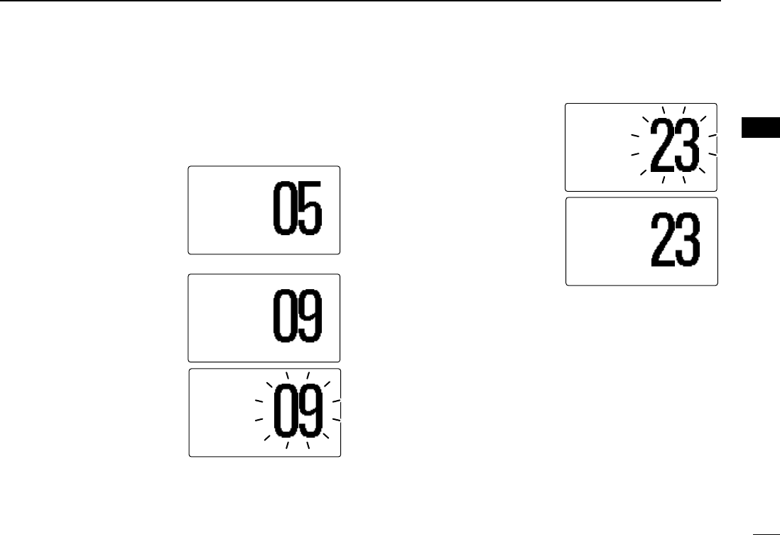
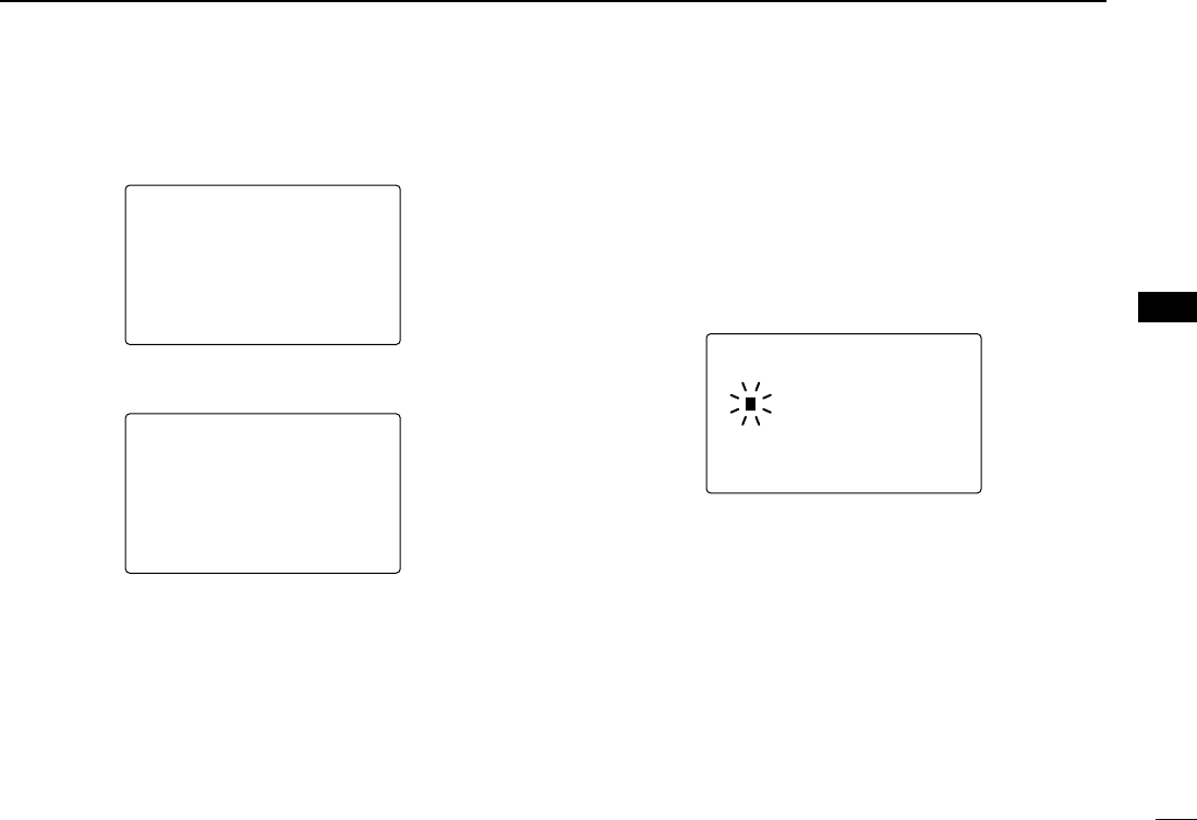
■Call channel programming
Call channel is used to select Channel 9 (default), however,
you can program the call channel with your most often-used
channels in each channel group for quick recall.
qWhile pushing and holding
[H/L], push [CH/WX•DUAL•
U/I/C] one or more times to
select the desired channel
group (U.S.A., International
or Canada) to be pro-
grammed.
wPush [16•9] for 1 sec. to se-
lect the call channel of the
selected channel group.
•“
CCAALLLL” and call channel
number appear.
ePush [16•9] again for 3 sec.
(until a long beep changes
to 2 short beeps) to enter
the call channel program-
ming condition.
• Channel number starts blink-
ing.
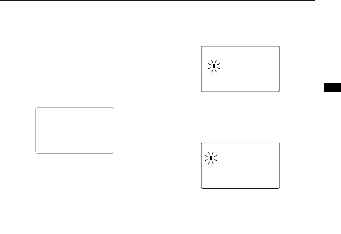
rRotate [DIAL] to select the
desired channel.
tPush [16•9] to program the
displayed channel as the
call channel.
• Push [CLR] to cancel.
• The channel number stops
blinking.
25W25W INTINT
DUPDUP
3434°34.506N34.506N
123123°23.236W23.236W
UTCUTC 1212:00:00 INTLINTL
25W25W INTINT CALLCALL
TAGTAG
3434°34.506N34.506N
123123°23.236W23.236W
UTCUTC 1212:00:00 CALLINGCALLING
25W25W INTINT CALLCALL
TAGTAG
3434°34.506N34.506N
123123°23.236W23.236W
UTCUTC 1212:00:00 CALLINGCALLING
25W25W INTINT CALLCALL
DUDUP
3434°34.506N34.506N
123123°23.236W23.236W
UTCUTC 1212:00:00 INTLINTL
25W25W INTINT CALLCALL
DUPDUP
3434°34.506N34.506N
123123°23.236W23.236W
UTCUTC 1212:00:00 INTLINTL
!IC-M504.qxd 05.12.28 11:29 AM Page 9 (1,1)
10
3BASIC OPERATION
New2001
■Channel comments
Memory channels can be labelled with alphanumeric com-
ments of up to 10 characters each for easy channel recogni-
tion.
Capital letters, small letters, 0 to 9, some symbols (– . /) and
space can be used.
qSelect the desired channel.
• Cancel Dualwatch, Tri-watch or Scan in advance.
wWhile pushing and holding
[H/L], push [16•9] to edit
the channel comment.
• A cursor and the first char-
acter start blinking alter-
nately.
eSelect the desired charac-
ter by rotating [DIAL].
• Push [16•9] or [CH/WX•DUAL•U/I/C] to move the cursor forward
or backward, respectively.
rRepeat step eto input all characters.
tPush [DIAL•ENTER] to input and set the comment.
• Push [CLR] to cancel.
• The cursor and the character stop blinking.
yRepeat steps qto tto program other channel com-
ments, if desired.
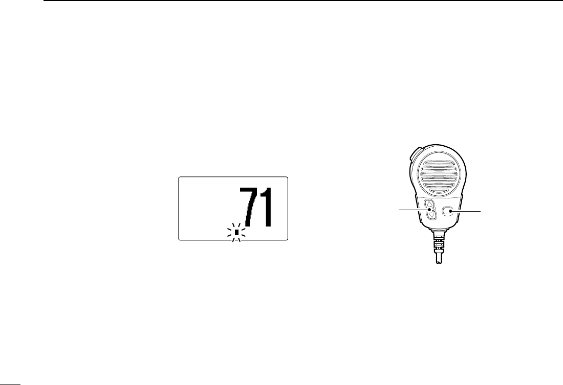
■Microphone Lock function
The Microphone Lock function electrically locks [Y]/[Z]and
[HI/LO] keys on the supplied microphone. This prevents ac-
cidental channel changes and function access.
➥While pushing and holding [HI/LO] on the microphone, turn
power ON to toggle the Lock function ON and OFF.
■Display backlight
The function display and keys can be backlit for better visibil-
ity under low light conditions.
➥While pushing and holding [H/L], rotate [DIAL] to adjust
the brightness of the LCD and key backlight.
• The backlight is adjustable in 7 levels and OFF.
[HI/LO]
[Y]/[Z]
25W25W INTINT
3434°34.506N34.506N
123123°23.236W23.236W
UTCUTC 1212:00:00PLEASURE__PLEASURE__
!IC-M504.qxd 05.12.28 11:29 AM Page 10 (1,1)
11
3
BASIC OPERATION
New2001
3
■Optional voice scrambler operation
DDActivating the scrambler
The optional voice scrambler provides private communica-
tions. In order to receive or send scrambled transmissions
you must first activate the scrambler function. To activate the
function, an optional scrambler unit is necessary. See pgs.
57, 62 for setting the scrambler unit. Ask your dealer for de-
tails.
The scrambler function automatically turns OFF when
Channel 16 or 70 is selected.
qRotate [DIAL] to select an operating channel other than
Channel 16 and 70.
wWhile pushing and holding [H/L], push [LO/DX•IC•SCRM]
to turn the optional scrambler function ON.
•“
SSCCRRMM” appears.
eTo turn the scrambler function OFF, repeat step w.
•“
SSCCRRMM” disappears.
DDProgramming scrambler codes
There are 32 codes (1 to 32) or 128 codes (0 to 127)* avail-
able for programming when the optional scrambler unit is in-
stalled. In order to understand one another, all transceivers
in your group must have the same scramble code. This func-
tion may not be available depending on dealer setting.
*Depends on the installed scrambler unit.
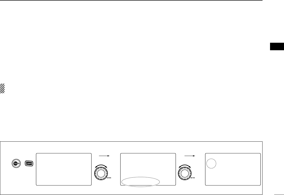
qTurn power OFF.
wWhile pushing [16•9], turn power ON to enter set mode.
eAfter the display appears, release [16•9].
rRotate [DIAL] to select the “SSccrraammbblleerr CCooddee,” push
[DIAL•ENTER].
tRotate [DIAL] to select the desired scrambler code.
yPush [DIAL•ENTER] to set and exit the scrambler code
item.
uPush [CLR], or rotate [DIAL] to select “EExxiitt,” push
[DIAL•ENTER] to exit set mode.
--Set Mode--
Scrambler Code
˘5
4
3
2
1
<ENT˘OK>
--Set Mode--
Dual/Tri
Beep
Contrast
Foghorn Frequency
Radio Power
Scrambler Type
˘Scrambler Code
--Set Mode--Mode--
˘Scan Type
Scan Timer
WX AlertAlert
Dual/Tri
Beep
Contrast
Foghorn FrequencyFrequency
+
to enter set mode.
Push
to select code,
then push.
Rotate
to select item,
then push.
Rotate
Select
Select
[Example]: Programming scrambler code 5.
!IC-M504.qxd 05.12.28 11:29 AM Page 11 (1,1)
12
SCAN OPERATION
New2001
4
■Scan types
Scanning is an efficient way to locate signals quickly over a
wide frequency range. The transceiver has Priority scan and
Normal scan.
When the Weather Alert function is turned ON, the previously
selected (last used) weather channel is also checked while
scanning. (p. 56)
Set the TAG channels (scanned channel) before scanning.
Clear the TAG channels which inconveniently stop scanning,
such as those for digital communication use. (Refer to right
page for details.)
Choose Priority or Normal scan in Set mode. (p. 55)
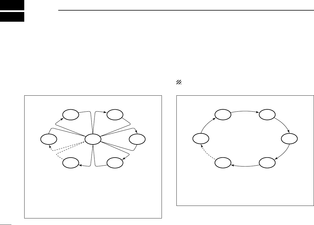
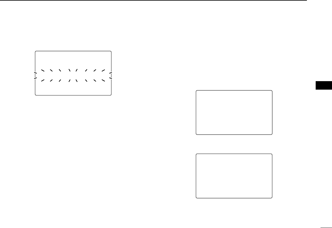
PRIORITY SCAN
Priority scan searches through all TAG channels in se-
quence while monitoring Channel 16. When a signal is de-
tected on Channel 16, scan pauses until the signal disap-
pears; when a signal is detected on a channel other than
Channel 16, scan becomes Dualwatch until the signal dis-
appears.
CH 06
CH 01
CH 16
CH 02
CH 05 CH 04
CH 03
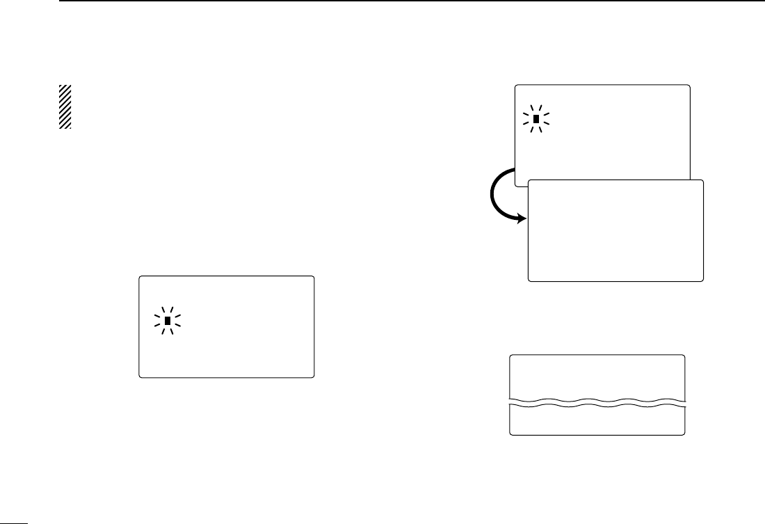
NORMAL SCAN
Normal scan, like Priority scan, searches through all TAG
channels in sequence. However, unlike Priority scan,
Channel 16 is not checked unless Channel 16 is set as a
TAG channel.
CH 01 CH 02
CH 06
CH 05 CH 04
CH 03
!IC-M504.qxd 05.12.28 11:29 AM Page 12 (1,1)
13
4
SCAN OPERATION
New2001
4
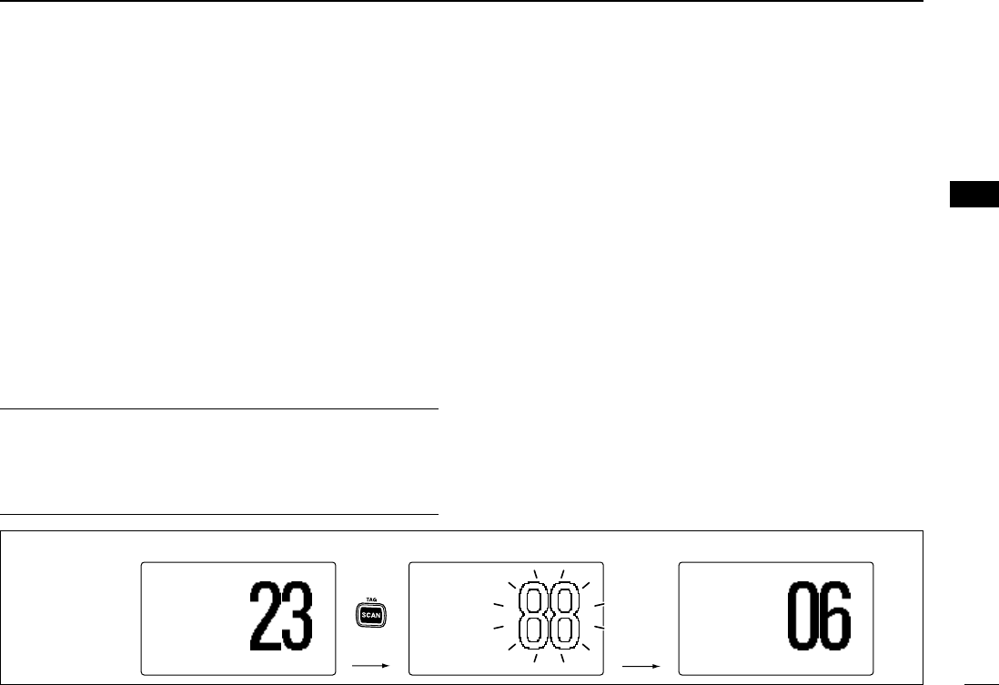
■Setting TAG channels
For more efficient scanning, add the desired channels as TAG
channels or clear the TAG for unwanted channels.
Channels that are not tagged will be skipped during scanning.
TAG channels can be assigned to each channel group (USA,
INT, CAN) independently.
qWhile pushing and holding [H/L], push [CH/WX•DUAL•U/I/C]
to select the desired channel group (USA, INT or CAN.)
wSelect the desired channel to be set as a TAG channel.
ePush [SCAN•TAG] for 1 sec. to set the displayed channel
as a TAG channel.
•“
TTAAGG” appears in the display.
rTo cancel the TAG channel setting, repeat step e.
•“
TTAAGG” disappears.
✔Clearing (or setting) all tagged channels
While pushing and holding [H/L], push [SCAN•TAG] for 3
sec. (until a long beep changes to 2 short beeps) to clear all
TAG channels setting in the channel group.
• Repeat above procedure to set all TAG channels.
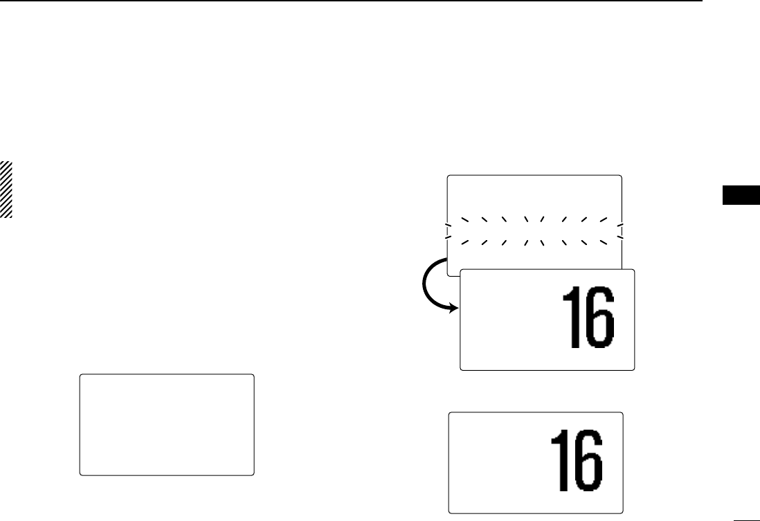
■Starting a scan
Set scan type (Priority or Normal scan) and scan resume
timer in advance, using Set mode. (p. 55)
qWhile pushing and holding [H/L], push [CH/WX•DUAL•
U/I/C] to select the desired channel group (USA, INT,
CAN) if desired.
wSet TAG channels as described at left.
eMake sure the squelch is closed to start a scan.
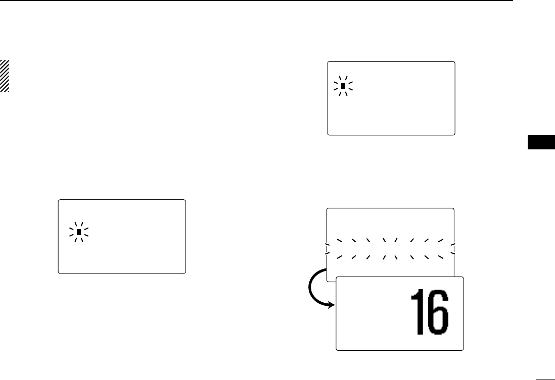
rPush [SCAN•TAG] to start Priority or Normal scan.
•“
PPRRII--SSCCAANN 1166” appears at the channel comment indicator
during Priority scan.
•“
NNOORRMMAALL SSCCAANN” appears at the channel comment indicator
during Normal scan.
• When a signal is detected, scan pauses until the signal disap-
pears or resumes after pausing 5 sec. according to Set mode
setting. (Channel 16 is still monitored during Priority scan.)
• Rotate [DIAL] to check the scanning TAG channels, to change
the scanning direction or resume the scan manually.
• A beep tone sounds and “16” blinks at the channel comment in-
dicator when a signal is received on Channel 16 during Priority
scan.
Push
Scan starts. When a signal is received
25W25W INTINT
DUPDUP
3434°34.506N34.506N
123123°23.236W23.236W
UTCUTC 1212:00:00 INTLINTL
BUSYBUSY 25W25W INTINT
DUPDUP
NORMALNORMAL SCANSCAN
3434°34.506N34.506N
123123°23.236W23.236W
UTCUTC 1212:00:00 SAFETYSAFETY
25W25W INTINT
DUPDUP
TAGTAG
NORMALNORMAL SCANSCAN
3434°34.506N34.506N
123123°23.236W23.236W
UTCUTC 1212:00:00
[Example]: Starting a normal scan.
!IC-M504.qxd 05.12.28 11:29 AM Page 13 (1,1)
14
DUALWATCH/TRI-WATCH
New2001
5
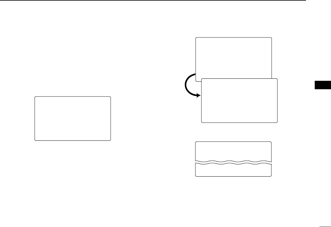
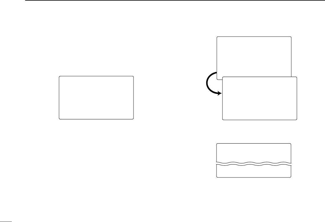
■Description
Dualwatch monitors Channel 16 while you are receiving
another channel; Tri-watch monitors Channel 16 and the call
channel while receiving another channel. Dualwatch/Tri-watch
is convenient for monitoring Channel 16 when you are oper-
ating on another channel.
■Operation
qSelect Dualwatch or Tri-watch in Set mode. (p. 56)
wRotate [DIAL] to select the desired operating channel.
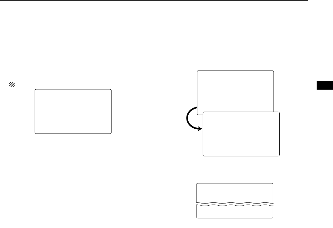
ePush [CH/WX•DUAL•U/I/C] for 1 sec. to start Dualwatch
or Tri-watch.
•“
DDUUAALL 1166” appears during Dualwatch; “TTRRII 1166” appears dur-
ing Tri-watch.
• A beep tone sounds when a signal is received on Channel 16.
rTo cancel Dualwatch/Tri-watch, push [CH/WX•DUAL•U/I/C]
again.
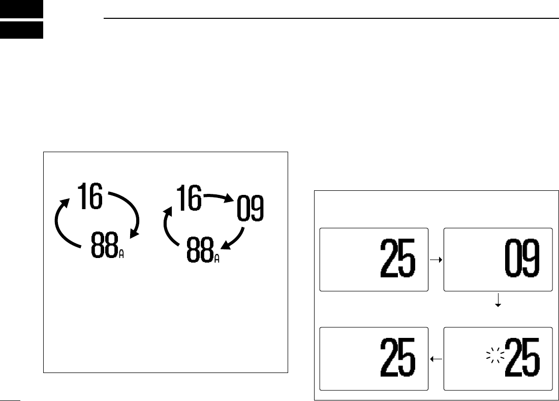
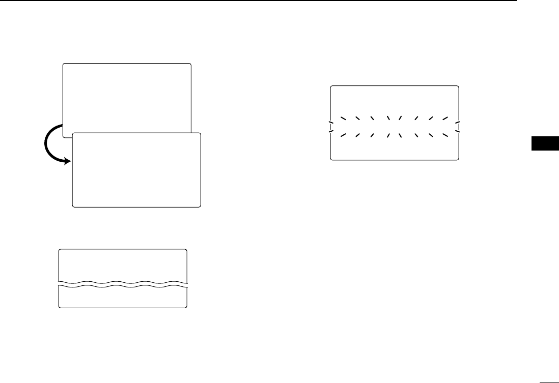
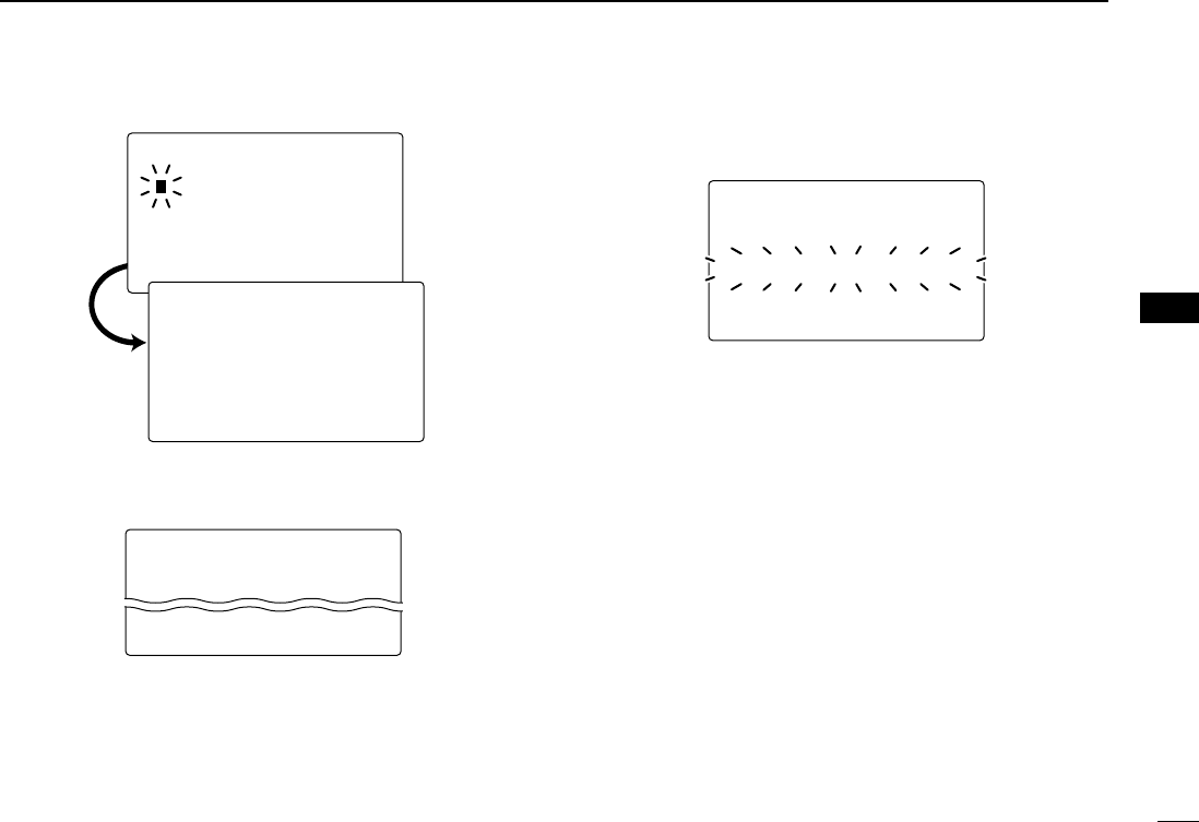
DUALWATCH/TRI-WATCH SIMULATION
• If a signal is received on Channel 16, Dualwatch/Tri-watch
pauses on Channel 16 until the signal disappears.
• If a signal is received on the call channel during Tri-watch,
Tri-watch becomes Dualwatch until the signal disappears.
• To transmit on the selected channel during Dualwatch/Tri-
watch, push and hold [PTT].
Dualwatch Tri-watch
Call channel
[Example]: Operating Tri-watch on INT Channel 25
25W25W INTINT
DUPDUP
TRITRI 1616
3434°34.506N34.506N
123123°23.236W23.236W
UTCUTC 1212:00:00 TELEPHONETELEPHONE
BUSYBUSY 25W25W INTINT CALLCALL
TAGTAG
TRITRI 1616
3434°34.506N34.506N
123123°23.236W23.236W
UTCUTC 1212:00:00 CALLINGCALLING
Tri-watch starts. Signal is received on call
channel.
BUSYBUSY 25W25W INTINT
DUPDUP
TRITRI 1616
3434°34.506N34.506N
123123°23.236W23.236W
UTCUTC 1212:00:00 TELEPHONETELEPHONE
Signal received on Channel
16 takes priority.
25W25W INTINT
DUPDUP
TRITRI 1616
3434°34.506N34.506N
123123°23.236W23.236W
UTCUTC 1212:00:00 TELEPHONETELEPHONE
Tri-watch resumes after the
signal disappears.
!IC-M504.qxd 05.12.28 11:29 AM Page 14 (1,1)
15
6
DSC OPERATION
5
6
■MMSI code programming
The 9-digit MMSI (Maritime Mobile Service Identity: DSC self
ID) code can be programmed at power ON.
This code programming can be performed only twice.
qTurn power OFF.
wWhile pushing [MENU], turn power ON to enter MMSI
code programming condition.
eAfter the display appears, release [MENU].
rPush [MENU] again to enter the DSC menu.
tRotate [DIAL] to select “SSeett uupp,” push [DIAL•ENTER].
yRotate [DIAL] to select “MMMMSSII CChheecckk,” push
[DIAL•ENTER].
uRotate [DIAL]
to set
the specific 9-digit MMSI code.
• Push [16•9] or [CH/WX•DUAL•U/I/C] to move the cursor forward
or backward, respectively.
• Push [CLR] to cancel and exit the condition to the set up menu.
iAfter input the 9-digit code, push [DIAL•ENTER] to set the
code.
• Returns to the set up menu.
oPush [CLR] or rotate [DIAL] to select “EExxiitt,” push
[DIAL•ENTER].
• Returns to the DSC menu.
• Repeat again to return to the normal operation condition.
--DSC--DSC Menu--Menu--
MMSI CheckMMSI Check
__________________
<CLR<CLR˘ExitExit /ENTENT˘OK>OK>
--DSC--DSC Menu--Menu--
SetSet upup
Add:INDVAdd:INDV IDID
Add:GroupAdd:Group IDID
DEL:INDVDEL:INDV IDID
DEL:GroupDEL:Group IDID
OffsetOffset TimeTime
˘MMSIMMSI CheckCheck
--DSC--DSC Menu--Menu--
SelectSelect ItemItem
PositionPosition InputInput
ReceivedReceived CallsCalls
˘SetSet upup
ExitExit
!IC-M504.qxd 05.12.28 11:29 AM Page 15 (1,1)

16
6DSC OPERATION
New2001
■MMSI code check
The 9-digit MMSI (DSC self ID) code can be checked.
qPush [MENU] to enter the DSC menu.
wRotate [DIAL] to select “SSeett uupp,” push [DIAL•ENTER].
eRotate [DIAL]
to select “MMMMSSII CChheecckk,” push
[DIAL•ENTER]
.
rCheck the 9-digit MMSI (DSC self ID) code.
tPush [CLR] or rotate [DIAL] to select “EExxiitt,” push
[DIAL•ENTER].
• Returns to the DSC menu.
• Repeat again to return to the normal operation condition.
--DSC Menu--
MMSI Check
123456789
<CLR˘Exit>
--DSC Menu--
Set up
DEL:Group ID
Offset Time
˘MMSI Check
Auto ACK
NMEA Output
Exit
--DSC Menu--
Select Item
Position Report
Polling Request
Received Calls
Distress Setting
˘Set up
Exit
!IC-M504.qxd 05.12.28 11:29 AM Page 16 (1,1)

17
6
DSC OPERATION
New2001
6
■DSC address ID
A total of 100 DSC address IDs can be programmed and
named with up to 10 characters.
DDProgramming Individual ID
qPush [MENU] to enter the DSC menu.
wRotate [DIAL] to select “SSeett uupp,” push [DIAL•ENTER].
eRotate [DIAL]
to select “AAdddd::IINNDDVV IIDD,” push
[DIAL•ENTER]
.
rRotate [DIAL]
to s
et the individual ID and ID name.
• Push [16•9] or [CH/WX•DUAL•U/I/C] to move the cursor forward
or backward, respectively.
• Push [CLR] to cancel and exit the condition to the set up menu.
• “FFuullll IIDD” appears when 100 DSC address IDs are already
set.
• After inputting the 9-digit ID code, push [DIAL•ENTER] or [16•9]
to set up a 10-character ID name.
tAfter inputting, push [DIAL•ENTER] to program.
yPush [CLR] or rotate [DIAL] to select “EExxiitt,” push
[DIAL•ENTER].
• Returns to the DSC menu.
• Repeat again to return to the normal operation condition.
--DSC Menu--
Add:Individual ID
Input 9 digits
_________
Input name
_________
<CLR˘Exit / ENT˘OK>
--DSC Menu--
Set up
˘Add:INDV ID
Add:Group ID
DEL:INDV ID
DEL:Group ID
Offset Time
MMSI Check
--DSC Menu--
Select Item
Position Report
Polling Request
Received Calls
Distress Setting
˘Set up
Exit
!IC-M504.qxd 05.12.28 11:29 AM Page 17 (1,1)

18
6DSC OPERATION
New2001
DDDeleting Individual ID
qPush [MENU] to enter the DSC menu.
wRotate [DIAL] to select “SSeett uupp,” push [DIAL•ENTER].
eRotate [DIAL]
to select “DDEELL::IINNDDVV IIDD,” push
[DIAL•ENTER]
.
• When no address ID is programmed, “
NNoo IIDD
” is displayed.
Push [CLR] to exit the condition.
rRotate [DIAL] to select the desired ID name for deleting.
tPush [DIAL•ENTER] to delete the address ID and returns
to the set up menu.
yPush [CLR] or rotate [DIAL] to select “EExxiitt,” push
[DIAL•ENTER].
• Returns to the DSC menu.
• Repeat again to return to the normal operation condition.
--DSC Menu--
Select ID
John
Paul
˘George
Michael
<CLR˘Exit / ENT˘OK>
--DSC Menu--
Set up
Add:INDV ID
Add:Group ID
˘DEL:INDV ID
DEL:Group ID
Offset Time
MMSI Check
--DSC Menu--
Select Item
Position Report
Polling Request
Received Calls
Distress Setting
˘Set up
Exit
!IC-M504.qxd 05.12.28 11:29 AM Page 18 (1,1)
19
6
DSC OPERATION
New2001
6
DDProgramming Group ID
qPush [MENU] to enter the DSC menu.
wRotate [DIAL] to select “SSeett uupp,” push [DIAL•ENTER].
eRotate [DIAL]
to select “AAdddd::GGrroouupp IIDD,” push
[DIAL•ENTER]
.
rRotate [DIAL]
to s
et the group ID and ID name.
• Push [16•9] or [CH/WX•DUAL•U/I/C] to move the cursor forward
or backward, respectively.
• Push [CLR] to cancel and exit the condition to the set up menu.
• “FFuullll IIDD” appears when 100 DSC address IDs are already
set.
• After inputting the 8-digit ID code, push [DIAL•ENTER] or [16•9]
to set up a 10-character ID name.
• 1st digit ‘0’ is fixed for a group ID.
tAfter inputting, push [DIAL•ENTER] to program.
yPush [CLR] or rotate [DIAL] to select “EExxiitt,” push
[DIAL•ENTER].
• Returns to the DSC menu.
• Repeat again to return to the normal operation condition.
--DSC Menu--
Add:Group ID
Input 8 digits
0________
Input name
_________
<CLR˘Exit / ENT˘OK>
--DSC Menu--
Set up
Add:INDV ID
˘Add:Group ID
DEL:INDV ID
DEL:Group ID
Offset Time
MMSI Check
--DSC Menu--
Select Item
Position Report
Polling Request
Received Calls
Distress Setting
˘Set up
Exit
!IC-M504.qxd 05.12.28 11:29 AM Page 19 (1,1)

20
6DSC OPERATION
New2001
DDDeleting Group ID
qPush [MENU] to enter the DSC menu.
wRotate [DIAL] to select “SSeett uupp,” push [DIAL•ENTER].
eRotate [DIAL]
to select “DDEELL::GGrroouupp IIDD,” push
[DIAL•ENTER]
.
• When no address ID is programmed, “
NNoo IIDD
” is displayed.
Push [CLR] to exit the condition.
rRotate [DIAL] to select the desired ID name for deleting.
tPush [DIAL•ENTER] to delete the group ID and returns to
the set up menu.
yPush [CLR] or rotate [DIAL] to select “EExxiitt,” push
[DIAL•ENTER].
• Returns to the DSC menu.
• Repeat again to return to the normal operation condition.
--DSC Menu--
Select ID
Icom
Group A
˘Group B
Group C
<CLR˘Exit / ENT˘OK>
--DSC Menu--
Set up
Add:INDV ID
Add:Group ID
DEL:INDV ID
˘DEL:Group ID
Offset Time
MMSI Check
--DSC Menu--
Select Item
Position Report
Polling Request
Received Calls
Distress Setting
˘Set up
Exit
!IC-M504.qxd 05.12.28 11:29 AM Page 20 (1,1)
21
6
DSC OPERATION
New2001
6
■
Position and time programming
A distress call should include the ship’s position and time
data. If no GPS is connected, your position and UTC (Univer-
sal Time Coordinated) time should be input manually. They
are included automatically when a GPS receiver (NMEA0183
ver. 2.0 or 3.01) is connected.
qPush [MENU] to enter the DSC menu.
wRotate [DIAL] to select “PPoossiittiioonn IInnppuutt,” and push
[DIAL•ENTER].
eThe position information appears. Set your position (lati-
tude and longitude) data with rotating [DIAL].
• Push [16•9] or [CH/WX•DUAL•U/I/C] to move the cursor forward
or backward, respectively.
• Rotate [DIAL] to edit N; North latitude or S; South latitude when
the cursor is on the ‘N’ or ‘S’ position, and W; West longitude or
E; East longitude when the cursor is on the ‘W’ or ‘E’ position.
• Push [CLR] for 1 sec. to clear the latitude/
longitude
data.
• Push [CLR] to cancel and exit the condition to the DSC menu.
rAfter setting the position data, push [DIAL•ENTER] to set
the time information appears. Set the current UTC time
with rotating [DIAL], then push [DIAL•ENTER].
• Push [16•9] or [CH/WX•DUAL•U/I/C] to move the cursor forward
or backward, respectively.
• Push [CLR] for 1 sec. to clear the UTC time data.
• Push [CLR] to cancel and exit the condition to the DSC menu.
--DSC Menu--
Input UTC Time
__:__ Null
<CLR<CLR 1sec1sec˘NullNull Data>Data>
<CLR<CLR˘ExitExit /ENTENT˘OK>OK>
--DSC Menu--
Input Position
Latitude
__°__.___N Null
Longitude
__°__.___W Null
<CLR<CLR 1sec1sec˘NullNull Data>Data>
<CLR<CLR˘ExitExit /ENTENT˘OK>OK>
--DSC Menu--
Select Item
˘Position Input
Individual Call
Group Call
All Ships Call
Position Request
Position Report
!IC-M504.qxd 05.12.28 11:29 AM Page 21 (1,1)

tPush [CLR] or rotate [DIAL] to select “EExxiitt,” push
[DIAL•ENTER].
• Returns to the DSC menu.
• Repeat again to return to the normal operation condition.
Manually programmed position data will be held for 23.5
hours only.
■Position and time indication
When a GPS receiver (NMEA0183 ver. 2.0 or 3.01) is con-
nected, the transceiver displays the current position and time.
When no GPS receiver is connected, the transceiver displays
the manually entered position and time.
A GPS receiver appropriate for the IC-M504 is not supplied
from Icom. A GPS receiver with NMEA0183 ver. 2.0 or 3.01
format is required for position and time indication. Ask your
dealer about suitable GPS receivers.
➥When connecting GPS receiver is compatible with sev-
eral sentence formatters, the order of input precedence
is ‘RMC,’ ‘GGA,’ ‘GNS’ and ‘GLL.’
➥When sentence formatter ‘RMC’ is received, time indi-
cation includes a date and UTC time only.
➥“????” may blink instead of position and time indications
when the GPS data is invalid, or has not been manually
updated after 4 hours.
25W INT
TAG
34°34.506N
123°23.236W
UTC 12:00 CALLING
22
6DSC OPERATION
New2001
!IC-M504.qxd 05.12.28 11:29 AM Page 22 (1,1)
23
6
DSC OPERATION
New2001
6
■Distress call
A distress call should be transmitted, if in the opinion of the
Master, the ship or a person is in distress and requires imme-
diate assistance.
NEVER USE THE DISTRESS CALL WHEN YOUR
SHIP OR A PERSON IS NOT IN AN EMERGENCY.
A DISTRESS CALL CAN BE USED ONLY WHEN
IMMEDIATE HELP IS NEEDED.
DDSimple call
qConfirm no distress call is being received.
wWhile lifting up the key cover, push [DISTRESS] for
5 sec. to transmit the distress call.
• Emergency channel (Channel 70) is automatically selected and
the distress call is transmitted.
• When no GPS is connected, input your position and UTC time, if
possible.
• While pushing [DISTRESS], the key backlighting is blinking.
eAfter transmitting the distress call, the transceiver waits for
an acknowledgment call on Channel 70.
• The distress call is automatically transmitted every 3.5 to 4.5
minutes.
• After 2 sec., the transceiver is set to Channel 16 automatically.
rAfter receiving the acknowledgment, reply using the mi-
crophone.
25W INT
TAG
Received
DistressACK
<Osaka Bay
<CLR
˘
Beep Off> CALLING
Distress Call
TX Complete
Now Waiting for ACK
<CLR<CLR˘CancelCancel ACK>ACK>
After 2 sec.
25W INT
TAG
Wait ACK
<CLR
˘
Cancel ACK> CALLING
Distress Call
Push for 5 sec.
!IC-M504.qxd 05.12.28 11:29 AM Page 23 (1,1)

24
6DSC OPERATION
New2001
➥A distress alert contains (default);
• Nature of distress : Undesignated distress
• Position data : GPS or manual input position data held
for 23.5 hrs or until the power is turned
OFF.
➥The distress call is repeated every 3.5–4.5 min., until re-
ceiving an ‘acknowledgement.’
➥Push [CLR] to cancel the ‘Call repeat’ mode.
➥“??” may blink instead of position and time indications
when the GPS data is invalid, or has not been manually
updated after 4 hours.
DDRegular call
The nature of the distress call should be included in the dis-
tress call.
qPush [MENU] to enter the DSC menu.
wRotate [DIAL] to select “DDiissttrreessss SSeettttiinngg,” and
push [DIAL•ENTER].
eRotate [DIAL] to select the nature of the distress, push
[DIAL•ENTER].
•‘
UUnnddeessiiggnnaatteedd,’ ‘EExxpplloossiioonn,’ ‘FFllooooddiinngg,’ ‘CCoollllii--
ssiioonn,’ ‘GGrroouunnddiinngg,’ ‘CCaappssiizziinngg,’ ‘SSiinnkkiinngg,’
‘AAddrriifftt(Disable adrift),’ ‘AAbbaannddoonniinngg(Abandoning ship),’
‘PPiirraaccyy(Piracy attack)’ and ‘MMOOBB(Man overboard)’ are avail-
able.
• The selected nature of the distress is stored for 10 minutes.
--DSC Menu--
Select Nature
Undesignated
˘Explosion
Flooding
Collision
<CLR<CLR˘ExitExit /ENTENT˘OK>OK>
--DSC Menu--
Select Item
All Ships Call
Position Request
Position Report
Polling Request
Received Calls
˘Distress Setting
!IC-M504.qxd 05.12.28 11:29 AM Page 24 (1,1)
25
6
DSC OPERATION
New2001
6
When a GPS receiver (NMEA0183 ver. 2.0 or 3.01) is con-
nected,
next steps r, t(
Current position/time program-
ming) do not appear. Go to step y.
rThe position information appears. Set your position (lati-
tude and longitude) data with rotating [DIAL].
• Push [16•9] or [CH/WX•DUAL•U/I/C] to move the cursor forward
or backward, respectively.
• Rotate [DIAL] to edit N; North latitude or S; South latitude when
the cursor is on the ‘N’ or ‘S’ position, and W; West longitude or
E; East longitude when the cursor is on the ‘W’ or ‘E’ position.
• Push [CLR] for 1 sec. to clear the latitude/
longitude
data.
• Push [CLR] to cancel and exit the condition to the DSC menu.
tAfter setting the position data, push [DIAL•ENTER] to set
the time information appears. Set the current UTC time
with rotating [DIAL], then push [DIAL•ENTER].
• Push [16•9] or [CH/WX•DUAL•U/I/C] to move the cursor forward
or backward, respectively.
• Push [CLR] for 1 sec. to clear the UTC time data.
• Push [CLR] to cancel and exit the condition to the DSC menu.
yPush [DISTRESS] for 5 sec. to transmit the distress call.
• While pushing [DISTRESS], the key backlighting is blinking.
uAfter transmitting the distress call, the transceiver waits for
an acknowledgment call on Channel 70.
• The distress call is automatically transmitted every 3.5 to 4.5 min.
• After 2 sec., the transceiver is set to Channel 16 automatically.
Distress Call
TX Complete
Now Waiting for ACK
<CLR<CLR˘CancelCancel ACK>ACK>
After 2 sec.
25W INT
TAG
Wait ACK
<CLR
˘
Cancel ACK> CALLING
--DSC Menu--
Input UTC Time
__:__ Null
<CLR<CLR 1sec1sec˘NullNull Data>Data>
<CLR<CLR˘ExitExit /ENTENT˘OK>OK>
--DSC Menu--
Input Position
Latitude
__°__.___N Null
Longitude
__°__.___W Null
<CLR<CLR 1sec1sec˘NullNull Data>Data>
<CLR<CLR˘ExitExit /ENTENT˘OK>OK>
!IC-M504.qxd 05.12.28 11:29 AM Page 25 (1,1)

26
6DSC OPERATION
New2001
iAfter receiving the acknowledgment, reply using the mi-
crophone.
➥A distress alert contains (default);
• Nature of distress : Selected nature of the distress
• Position data : GPS or manual input position data held
for 23.5 hrs or until the power is turned
OFF.
➥The distress call is repeated every 3.5–4.5 min., until re-
ceiving an ‘acknowledgement.’
➥Push [CLR] to cancel the ‘Call repeat’ mode.
➥“????” may blink instead of position and time indications
when the GPS data is invalid, or has not been manually
updated after 4 hours.
■Transmitting DSC calls
To ensure correct operation of the DSC function, please
make sure you set the squelch correctly. (p. 8)
DDTransmitting an individual call
The individual call function allows you to transmit a DSC sig-
nal to a specific ship only.
qPush [MENU] to enter the DSC menu.
wRotate [DIAL] to select “IInnddiivviidduuaall CCaallll,” push
[DIAL•ENTER].
•“
PPoossiittiioonn IInnppuutt” item appears when
a GPS receiver
(NMEA0183 ver. 2.0 or 3.01) is not connected.
--DSC Menu--
Select Item
Position Input
˘Individual Call
Group Call
All Ships Call
Position Request
Position Report
25W INT
TAG
Received
DistressACK
<Osaka Bay
<CLR
˘
Beep Off> CALLING
!IC-M504.qxd 05.12.28 11:29 AM Page 26 (1,1)
27
6
DSC OPERATION
New2001
6
eRotate [DIAL] to select the desired pre-programmed indi-
vidual address or “MMaannuuaall IInnppuutt,” push
[DIAL•ENTER].
• The ID code for the individual call can be set in advance. (p. 16)
• When “MMaannuuaall IInnppuutt” is selected, set the 9-digit ID code
for the individual you wish to call with rotating [DIAL].
1st digit must not be ‘0’.
rRotate [DIAL] to select a desired intership channel, push
[DIAL•ENTER].
• Intership channels are already preset into the transceiver in rec-
ommending order.
tPush [DIAL•ENTER] to transmit the individual call.
• If Channel 70 is busy, the transceiver stands by until the channel
becomes clear.
--DSC Menu--
Individual Call
Transmitting
--DSC Menu--
Select Intership CH
˘08
69
77
06
<CLR˘Exit / ENT˘OK>
--DSC Menu--
Individual Call Ready
<CLR˘Exit / ENT˘OK>
--DSC Menu--
Select Address
Manual Input
John
˘Paul
George
Michael
<CLR˘Exit / ENT˘OK>
!IC-M504.qxd 05.12.28 11:29 AM Page 27 (1,1)
28
6DSC OPERATION
New2001
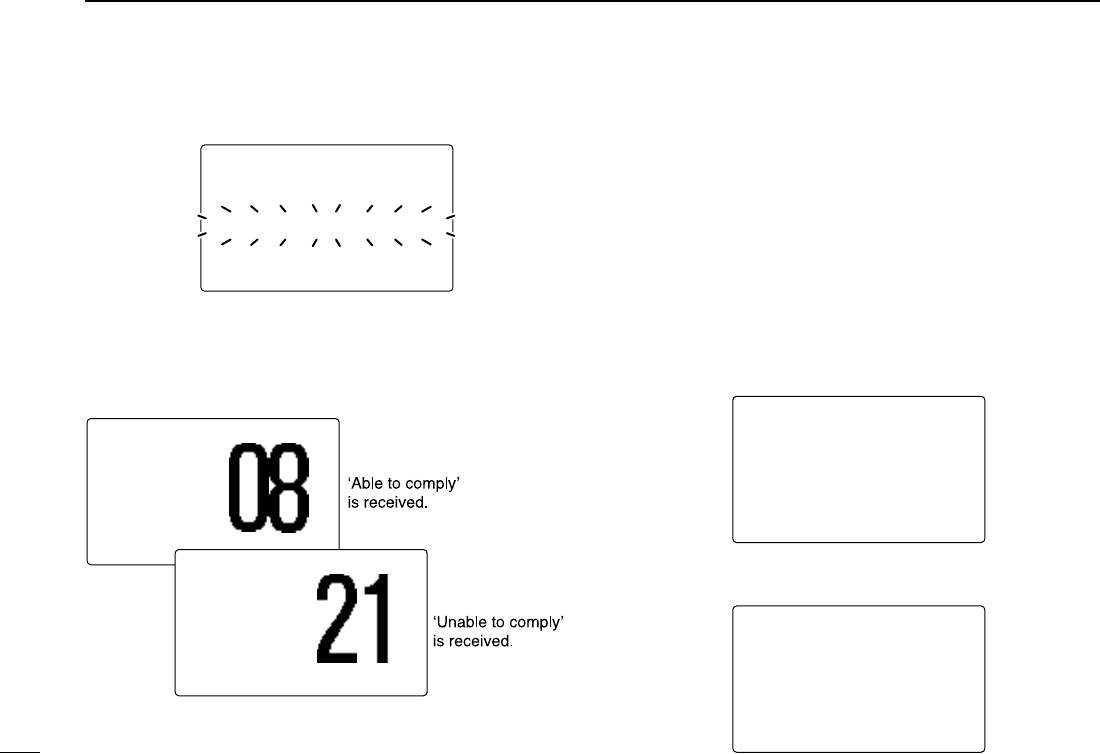
yStandby on Channel 70 until an acknowledgement is re-
ceived.
uWhen the acknowledgement ‘Able to comply’ is received,
the specified channel (in step r) is selected with beeps
automatically. Or, when the acknowledgement ‘Unable to
comply’ is received, the display returns to the operated
channel (before enter the DSC menu) with beeps.
iPush [CLR] to stop the beep, then push and hold [PTT] to
communicate your message to the responding ship.
DDTransmitting an individual acknowledgement
When receiving an individual call, you can transmit an ac-
knowledgement (‘Able to comply’ or ‘Unable to comply’) by
using the on screen prompts (see page 38 for details). Alter-
natively, you can send an acknowledgement through the
menu system as follows.
qPush [MENU] to enter the DSC menu.
wRotate [DIAL] to select “IInnddiivviidduuaall AACCKK,” push
[DIAL•ENTER].
•“
PPoossiittiioonn IInnppuutt” item appears when a GPS receiver
(NMEA0183 ver. 2.0 or 3.01) is not connected.
•“
IInnddiivviidduuaall AACCKK” item appears after an individual call is
received.
eRotate [DIAL] to select the desired individual address or
ID code, push [DIAL•ENTER].
--DSC Menu--
Select Address
John
˘Paul
George
Michael
<CLR˘Exit / ENT˘OK>
--DSC Menu--
Select Item
Position Input
Individual Call
˘Individual ACK
Group Call
All Ships Call
Position Request
25W INT
Received
INDV ACK
<John
<CLR
˘
Beep Off> COMMERCIAL
25W INT
DUP
Received
Unable ACK
<John
<CLR
˘
Beep Off> INTL
--DSC Menu--
Individual Call
TX Complete
Now Waiting for ACK
<CLR˘Exit>
!IC-M504.qxd 05.12.28 11:29 AM Page 28 (1,1)

29
6
DSC OPERATION
New2001
6
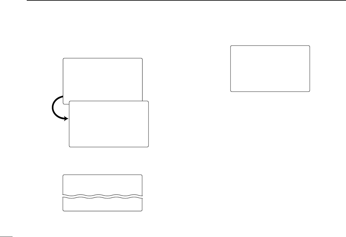
rRotate [DIAL] to select that you can comply to the call or
not from “AAbbllee ttoo CCoommppllyy” or “UUnnaabbllee ttoo CCoomm--
ppllyy,” push [DIAL•ENTER].
• When “UUnnaabbllee ttoo CCoommppllyy” is selected, the reason “No
Reason Given” will be transmitted.
tPush [DIAL•ENTER] to transmit the acknowledgement call
to the selected station.
yAfter the individual acknowledgement call has been trans-
mitted, the specified channel (specified by the calling sta-
tion) is selected automatically when “AAbbllee ttoo CCoomm--
ppllyy” is selected, or returns to the previous condition
(before entering the DSC menu) when “UUnnaabbllee ttoo
CCoommppllyy” is selected in step r.
DDTransmitting a group call
The group call function allows you to transmit a DSC signal to
a specific group only.
qPush [MENU] to enter the DSC menu.
wRotate [DIAL] to select “GGrroouupp CCaallll,” push
[DIAL•ENTER].
•“
PPoossiittiioonn IInnppuutt” item appears when a GPS receiver
(NMEA0183 ver. 2.0 or 3.01) is not connected.
eRotate [DIAL] to select the desired pre-programmed group
address or “MMaannuuaall IInnppuutt,” push [DIAL•ENTER].
• The ID code for the group call can be set in advance. (p. 18)
• When “MMaannuuaall IInnppuutt” is selected, set the 8-digit ID code
for the group you wish to call with rotating [DIAL].
--DSC Menu--
Select Address
Manual Input
˘Icom
Coast station
<CLR˘Exit / ENT˘OK>
--DSC Menu--
Select Item
Position Input
Individual Call
˘Group Call
All Ships Call
Position Request
Position Report
--DSC Menu--
Select Action
˘Able to Comply
Unable to Comply
<CLR˘Exit / ENT˘OK>
--DSC Menu--
Individual ACK Ready
<CLR˘Exit / ENT˘OK>
!IC-M504.qxd 05.12.28 11:29 AM Page 29 (1,1)
30
6DSC OPERATION
New2001
rRotate [DIAL] to select a desired intership channel, push
[DIAL•ENTER].
• Intership channels are already preset into the transceiver in rec-
ommending order.
tPush [DIAL•ENTER] to transmit the group call.
• If Channel 70 is busy, the transceiver stands by until the channel
becomes clear.
yAfter the group call has been transmitted, the following in-
dication is displayed.
uPush [CLR] to exit the condition and selects the specified
intership channel in step rautomatically.
• Even if [CLR] hasn’t been pushed, the transceiver selects the
specified intership channel in step rautomatically after 2 sec. of
inactivity.
--DSC Menu--
Group Call
TX Complete
<CLR˘Exit>
--DSC Menu--
Group Call
Transmitting
--DSC Menu--
Select Intership CH
˘08
69
77
06
<CLR˘Exit / ENT˘OK>
--DSC Menu--
Group Call Ready
<CLR˘Exit / ENT˘OK>
!IC-M504.qxd 05.12.28 11:29 AM Page 30 (1,1)
31
6
DSC OPERATION
New2001
6
DDTransmitting an all ships call
Large ships use Channel 70 as their ‘listening channel.’ When
you want to announce a message to these ships, use the all
ships call function.
qPush [MENU] to enter the DSC menu.
wRotate [DIAL] to select “AAllll SShhiippss CCaallll,” and push
[DIAL•ENTER].
•“
PPoossiittiioonn IInnppuutt” item appears when a GPS receiver
(NMEA0183 ver. 2.0 or 3.01) is not connected.
eRotate [DIAL] to select the desired category, push
[DIAL•ENTER].
• Output power of ‘Routine’ category is 1 W (low power) only.
• The selectable category may differ according to the programmed
setting. Ask your dealer for the available categories.
rPush [DIAL•ENTER] to transmit the all ships call.
• Channel 70 is selected and the all ships call is transmitted.
--DSC Menu--
All Ships Call
Transmitting
--DSC Menu--
Select Category
˘Routine
Safety
Urgency
<CLR˘Exit / ENT˘OK>
--DSC Menu--
All Ships Call Ready
<CLR˘Exit / ENT˘OK>
--DSC Menu--
Select Item
Position Input
Individual Call
Group Call
˘All Ships Call
Position Request
Position Report
!IC-M504.qxd 05.12.28 11:29 AM Page 31 (1,1)

32
6DSC OPERATION
New2001
tAfter the all ships call has been transmitted, the following
indication is displayed.
yPush [CLR] to exit the condition and selects Channel 16
automatically.
• Even if [CLR] hasn’t been pushed, the transceiver automatically
selects Channel 16 after 2 sec. of inactivity.
DDTransmitting a position request call
Transmit a position request call when you want to know a
specific ship’s current position, etc.
qPush [MENU] to enter the DSC menu.
wRotate [DIAL] to select “PPoossiittiioonn RReeqquueesstt,” push
[DIAL•ENTER].
•“
PPoossiittiioonn IInnppuutt” item appears when a GPS receiver
(NMEA0183 ver. 2.0 or 3.01) is not connected.
eRotate [DIAL] to select the desired pre-programmed indi-
vidual address or “MMaannuuaall IInnppuutt,” push
[DIAL•ENTER].
• The ID code can be set in advance. (p. 17)
• When “MMaannuuaall IInnppuutt” is selected, set the 9-digit ID code
for the individual you wish to call with rotating [DIAL].
--DSC Menu--
Select Item
Position Input
Individual Call
Group Call
All Ships Call
˘Position Request
Position Report
--DSC Menu--
All Ships Call
TX Complete
<CLR˘Exit>
!IC-M504.qxd 05.12.28 11:29 AM Page 32 (1,1)
33
6
DSC OPERATION
New2001
6
rPush [DIAL•ENTER] to transmit the position request call.
• If Channel 70 is busy, the transceiver stands by until the channel
becomes clear.
tAfter the position request call has been transmitted, the fol-
lowing indication is displayed.
yPush [CLR] to return to the previous indication before en-
tering the DSC menu.
• Even if [CLR] hasn’t been pushed, the display automatically re-
turns to the previous indication after 2 sec. of inactivity.
--DSC Menu--
Position Request
TX Complete
Now Waiting for ACK
<CLR˘Exit>
--DSC Menu--
Position Request
Transmitting
--DSC Menu--
Select Address
Manual Input
John
˘Paul
George
Michael
<CLR˘Exit / ENT˘OK>
--DSC Menu--
POS Request Ready
<CLR˘Exit / ENT˘OK>
!IC-M504.qxd 05.12.28 11:29 AM Page 33 (1,1)

34
6DSC OPERATION
New2001
DDTransmitting a position report call
Transmit a position report call when you want to announce
your own position to a specific ship and to get an answer, etc.
qPush [MENU] to enter the DSC menu.
wRotate [DIAL] to select “PPoossiittiioonn RReeppoorrtt,” push
[DIAL•ENTER].
•“
PPoossiittiioonn IInnppuutt” item appears when a GPS receiver
(NMEA0183 ver. 2.0 or 3.01) is not connected.
eRotate [DIAL] to select the desired pre-programmed indi-
vidual address or “MMaannuuaall IInnppuutt,” push
[DIAL•ENTER].
• The ID code can be set in advance. (p. 17)
• When “MMaannuuaall IInnppuutt” is selected, set the 9-digit ID code
for the individual you wish to call with rotating [DIAL].
When a GPS receiver (NMEA0183 ver. 2.0 or 3.01) is con-
nected,
next steps r, t(
Current position/time program-
ming) do not appear. Go to step y.
rThe position information appears. Set your position (lati-
tude and longitude) data with rotating [DIAL].
• Push [16•9] or [CH/WX•DUAL•U/I/C] to move the cursor forward
or backward, respectively.
• Rotate [DIAL] to edit N; North latitude or S; South latitude when
the cursor is on the ‘N’ or ‘S’ position, and W; West longitude or
E; East longitude when the cursor is on the ‘W’ or ‘E’ position.
• Push [CLR] for 1 sec. to clear the latitude/
longitude
data.
• Push [CLR] to cancel and exit the condition to the DSC menu.
tAfter setting the position data, push [DIAL•ENTER] to set
the time information appears. Set the current UTC time
with rotating [DIAL], then push [DIAL•ENTER].
• Push [16•9] or [CH/WX•DUAL•U/I/C] to move the cursor forward
or backward, respectively.
• Push [CLR] for 1 sec. to clear the UTC time data.
• Push [CLR] to cancel and exit the condition to the DSC menu.
--DSC Menu--
Input Position
Latitude
__°__.___N Null
Longitude
__°__.___W Null
<CLR<CLR 1sec1sec˘NullNull Data>Data>
<CLR<CLR˘ExitExit /ENTENT˘OK>OK>
--DSC Menu--
Select Address
Manual Input
John
˘Paul
George
Michael
<CLR˘Exit / ENT˘OK>
--DSC Menu--
Select Item
Position Input
Individual Call
Group Call
All Ships Call
Position Request
˘Position Report
!IC-M504.qxd 05.12.28 11:29 AM Page 34 (1,1)
35
6
DSC OPERATION
New2001
6
yPush [DIAL•ENTER] to transmit the position report call.
• If Channel 70 is busy, the transceiver stands by until the channel
becomes clear.
uAfter the position report call has been transmitted, the fol-
lowing indication is displayed.
iPush [CLR] to return to the previous indication before en-
tering the DSC menu.
• Even if [CLR] hasn’t been pushed, the display automatically re-
turns to the previous indication after 2 sec. of inactivity.
--DSC Menu--
Position Report
TX Complete
Now Waiting for ACK
<CLR˘Exit>
--DSC Menu--
Position Report
Transmitting
--DSC Menu--
Input UTC Time
__:__ Null
<CLR<CLR 1sec1sec˘NullNull Data>Data>
<CLR<CLR˘ExitExit /ENTENT˘OK>OK>
--DSC Menu--
Position Report Ready
<CLR˘Exit / ENT˘OK>
!IC-M504.qxd 05.12.28 11:29 AM Page 35 (1,1)
36
6DSC OPERATION
New2001
DDTransmitting a polling request call
Transmit a polling request call when you want to know a spe-
cific ship is in the communication area, etc.
qPush [MENU] to enter the DSC menu.
wRotate [DIAL] to select “PPoolllliinngg RReeqquueesstt,” push
[DIAL•ENTER].
eRotate [DIAL] to select the desired pre-programmed indi-
vidual address or “MMaannuuaall IInnppuutt,” push
[DIAL•ENTER].
• The ID code can be set in advance. (p. 17)
• When “MMaannuuaall IInnppuutt” is selected, set the 9-digit ID code
for the individual you wish to call with rotating [DIAL].
rPush [DIAL•ENTER] to transmit the polling request call.
• If Channel 70 is busy, the transceiver stands by until the channel
becomes clear.
--DSC Menu--
Polling Request
Transmitting
--DSC Menu--
Select Address
Manual Input
John
˘Paul
George
Michael
<CLR˘Exit / ENT˘OK>
--DSC Menu--
Polling Request Ready
<CLR˘Exit / ENT˘OK>
--DSC Menu--
Select Item
Individual Call
Group Call
All Ships Call
Position Request
Position Report
˘Polling Request
!IC-M504.qxd 05.12.28 11:29 AM Page 36 (1,1)
37
6
DSC OPERATION
New2001
6
tAfter the polling request call has been transmitted, the fol-
lowing indication is displayed.
yPush [CLR] to return to the previous indication before en-
tering the DSC menu.
• Even if [CLR] hasn’t been pushed, the display automatically re-
turns to the previous indication after 2 sec. of inactivity.
DDTransmitting a position request reply call
Transmit a position request reply call when a position request
call is received.
qPush [MENU] to enter the DSC menu.
wRotate [DIAL] to select “PPoossiittiioonn RReeppllyy,” push
[DIAL•ENTER].
•“
PPoossiittiioonn RReeppllyy” item appears after a position request
call is received.
eRotate [DIAL] to select the desired individual address or
ID code, push [DIAL•ENTER].
--DSC Menu--
Select Address
John
˘Paul
George
Michael
<CLR˘Exit / ENT˘OK>
--DSC Menu--
Select Item
Position Input
Individual Call
Group Call
All Ships Call
Position Request
˘Position Reply
--DSC Menu--
Polling Request
TX Complete
Now Waiting for ACK
<CLR˘Exit>
!IC-M504.qxd 05.12.28 11:29 AM Page 37 (1,1)
38
6DSC OPERATION
New2001
When a GPS receiver (NMEA0183 ver. 2.0 or 3.01) is con-
nected,
next steps r, t(
Current position/time program-
ming) do not appear. Go to step y.
rThe position information appears. Set your position (lati-
tude and longitude) data with rotating [DIAL].
• Push [16•9] or [CH/WX•DUAL•U/I/C] to move the cursor forward
or backward, respectively.
• Rotate [DIAL] to edit N; North latitude or S; South latitude when
the cursor is on the ‘N’ or ‘S’ position, and W; West longitude or
E; East longitude when the cursor is on the ‘W’ or ‘E’ position.
• Push [CLR] for 1 sec. to clear the latitude/
longitude
data.
• Push [CLR] to cancel and exit the condition to the DSC menu.
tAfter setting the position data, push [DIAL•ENTER] to set
the time information appears. Set the current UTC time
with rotating [DIAL], then push [DIAL•ENTER].
• Push [16•9] or [CH/WX•DUAL•U/I/C] to move the cursor forward
or backward, respectively.
• Push [CLR] for 1 sec. to clear the UTC time data.
• Push [CLR] to cancel and exit the condition to the DSC menu.
yPush [DIAL•ENTER] to transmit the position request reply
call to the selected station.
• Your position data is transmitted, when [DIAL•ENTER] is
pushed.
--DSC Menu--
Position Reply
Transmitting
--DSC Menu--
Input UTC Time
__:__ Null
<CLR<CLR 1sec1sec˘NullNull Data>Data>
<CLR<CLR˘ExitExit /ENTENT˘OK>OK>
--DSC Menu--
Position Reply Ready
<CLR˘Exit / ENT˘OK>
--DSC Menu--
Input Position
Latitude
__°__.___N Null
Longitude
__°__.___W Null
<CLR<CLR 1sec1sec˘NullNull Data>Data>
<CLR<CLR˘ExitExit /ENTENT˘OK>OK>
!IC-M504.qxd 05.12.28 11:29 AM Page 38 (1,1)

39
6
DSC OPERATION
New2001
6
DDTransmitting a position report reply call
Transmit a position report reply call when a position report call
is received.
qPush [MENU] to enter the DSC menu.
wRotate [DIAL] to select “PPOOSS RReeppoorrtt RReeppllyy,” push
[DIAL•ENTER].
•“
PPOOSS RReeppoorrtt RReeppllyy” item appears after a position report
call is received.
eRotate [DIAL] to select the desired individual address or
ID code, push [DIAL•ENTER].
rPush [DIAL•ENTER] to transmit the position report reply
call to the selected station.
--DSC Menu--
Position Report Reply
Transmitting
--DSC Menu--
Select Address
Manual Input
John
˘Paul
George
Michael
<CLR˘Exit / ENT˘OK>
--DSC Menu--
POS REP Reply Ready
<CLR˘Exit / ENT˘OK>
--DSC Menu--
Select Item
Individual Call
Group Call
All Ships Call
Position Request
Position Report
˘POS Report Reply
!IC-M504.qxd 05.12.28 11:29 AM Page 39 (1,1)

40
6DSC OPERATION
New2001
DDTransmitting a polling request reply call
Transmit a polling reply call when a polling request call is re-
ceived.
qPush [MENU] to enter the DSC menu.
wRotate [DIAL] to select “PPoolllliinngg RReeppllyy,” push
[DIAL•ENTER].
•“
PPoolllliinngg RReeppllyy” item appears after a polling request call
is received.
eRotate [DIAL] to select the desired individual address or
ID code, push [DIAL•ENTER].
rPush [DIAL•ENTER] to transmit the polling request call to
the selected station.
--DSC Menu--
Polling Reply
Transmitting
--DSC Menu--
Select Address
Manual Input
John
˘Paul
George
Michael
<CLR˘Exit / ENT˘OK>
--DSC Menu--
Polling Reply Ready
<CLR˘Exit / ENT˘OK>
--DSC Menu--
Select Item
Group Call
All Ships Call
Position Request
Position Report
Polling Request
˘Polling Reply
!IC-M504.qxd 05.12.28 11:29 AM Page 40 (1,1)

41
6
DSC OPERATION
New2001
6
■Receiving DSC calls
DDReceiving a distress call
While monitoring Channel 70 and a distress call is received:
➥The emergency alarm sounds for 2 minutes.
• Push [CLR] to stop the alarm.
➥“RReecceeiivveedd DDiissttrreessss” appears in the display, then
Channel 16 is automatically selected.
➥Continue monitoring Channel 16 as a coast station may re-
quire assistance.
DDReceiving a distress acknowledgement
While monitoring Channel 70 and a distress acknowledge-
ment to other ship is received:
➥The emergency alarm sounds for 2 minutes.
• Push [CLR] to stop the alarm.
➥“RReecceeiivveedd DDiissttrreessssAACCKK” appears in the display,
then Channel 16 is automatically selected.
DDReceiving a distress relay call
While monitoring Channel 70 and a distress relay acknowl-
edgement is received:
➥The emergency alarm sounds for 2 minutes.
• Push [CLR] to stop the alarm.
➥“RReecceeiivveedd DDiissttrreessssRRLLYY” appears in the display,
then Channel 16 is automatically selected.
25W INT
TAG
Received
DistressRLY
<John
<CLR
˘
Beep Off> CALLING
25W INT
TAG
Received
DistressACK
<Osaka Bay
<CLR
˘
Beep Off> CALLING
25W INT
TAG
Received
Distress
<Paul
<CLR
˘
Beep Off> CALLING
!IC-M504.qxd 05.12.28 11:29 AM Page 41 (1,1)

42
6DSC OPERATION
New2001
DDReceiving an individual call
While monitoring Channel 70 and an individual call is re-
ceived:
➥The emergency alarm or beeps sound depending on the
received category.
➥“RReecceeiivveedd IInnddiivviidduuaall” appears in the display.
➥Push [CLR] to stop the beep, then push [DIAL•ENTER] to
reply the call and select the channel specified by the calling
station for voice communication (depending on your reply-
ing condition see p. 28 for individual acknowledgement call
procedure for details.); push [CLR] to ignore the individual
call.
DDReceiving a group call
While monitoring Channel 70 and a group call is received:
➥The emergency alarm or beeps sound depending on the
received category.
➥“RReecceeiivveedd GGrroouupp” appears in the display.
➥Push [CLR] to stop the beep, then push [DIAL•ENTER] to
select the channel specified by the calling station for voice
communication; push [CLR] to ignore the group call.
DDReceiving an all ships call
While monitoring Channel 70 and an all ships call is received:
➥The emergency alarm sounds when the category is ‘Dis-
tress’ or ‘Urgency’; beeps sound for 2 minutes.
➥“RReecceeiivveedd AAllll SShhiippss” appears in the display.
➥Push [CLR] to stop the beep, then push [DIAL•ENTER] to
monitor channel 16 for an announcement from the calling
vessel, push [CLR] to ignore the call.
25W INT
TAG
Received
Group
<Icom
<CLR
˘
Beep Off> SAFETY
25W INT
TAG
Received
Individual
<Paul
<CLR
˘
Beep Off> SAFETY
!IC-M504.qxd 05.12.28 11:29 AM Page 42 (1,1)

43
6
DSC OPERATION
New2001
6
DDReceiving a geographical area call
While monitoring Channel 70 and a geographical area call
(for the area you are in) is received:
➥Emergency alarm or beeps sound depending on the re-
ceived category.
➥“RReecceeiivveedd GGeeooggrraapphhiicc” appears in the display.
➥Push [CLR] to stop the beep, then push [DIAL•ENTER] to
change to the channel specified by the calling station for
voice communication; push other key to ignore the geo-
graphical area call.
➥Monitor the selected channel for an announcement from
the calling station.
When no GPS receiver is connected or if there is a prob-
lem with the connected receiver, all geographical area calls
are received, regardless of your position.
DDReceiving a position request call
While monitoring Channel 70 and a position request call is re-
ceived:
➥“RReecceeiivveedd PPOOSS RReeqquueesstt” appears in the display.
➥Push [CLR] to stop the beep, then push [DIAL•ENTER] to
reply to the position request call; push [CLR] to ignore the
position request call.
DDReceiving a position report call
While monitoring Channel 70 and a position report call is re-
ceived:
➥“RReecceeiivveedd PPOOSS RReeppoorrtt” appears in the display.
➥Push [CLR] to stop the beep, then push [DIAL•ENTER] to
reply to the position report call; push [CLR] to ignore the
position report call.
25W INT
TAG
Received
POS Report
<Paul
<CLR
˘
Beep Off> SAFETY
25W INT
TAG
Received
POS Request
<Paul
<CLR
˘
Beep Off> SAFETY
25W INT
TAG
Received
Geographic
<Osaka Bay
<CLR
˘
Beep Off> SAFETY
25W INT
TAG
Received
All Ships
<Paul
<CLR
˘
Beep Off> SAFETY
!IC-M504.qxd 05.12.28 11:29 AM Page 43 (1,1)

44
6DSC OPERATION
New2001
DDReceiving a polling request call
While monitoring Channel 70 and a polling request call is re-
ceived:
➥“RReecceeiivveedd PPOOLLLL RREEQQ” appears in the display.
➥Push [CLR] to stop the beep, then push [DIAL•ENTER] to
reply to the call; push [CLR] to ignore the call.
DDReceiving a position request reply call
While monitoring Channel 70 and a position request reply call
is received:
➥“RReecceeiivveedd PPOOSS RReeppllyy” appears in the display.
➥Push [CLR] to stop the beep, then push [DIAL•ENTER] to
display the position information; push [CLR] to ignore the
reply call.
DDReceiving a position report reply call
While monitoring Channel 70 and a position report reply call
is received:
➥“RReecceeiivveedd PPOOSS RReeppllyy” appears in the display.
➥Push [CLR] to stop the beep, then push [DIAL•ENTER] to
display the position information; push [CLR] to ignore the
reply call.
DDReceiving a polling request reply call
While monitoring Channel 70 and a polling request reply call
is received:
➥“RReecceeiivveedd PPOOLLLL RReeppllyy” appears in the display.
➥Push [CLR] to stop the beep, then push [DIAL•ENTER] to
display the position information; push [CLR] to ignore the
reply call.
25W INT
TAG
Received
POLL Reply
<Paul
<CLR
˘
Beep Off> SAFETY
25W INT
TAG
Received
POS Reply
<Paul
<CLR
˘
Beep Off> SAFETY
25W INT
TAG
Received
POS Reply
<Paul
<CLR
˘
Beep Off> SAFETY
25W INT
TAG
Received
POLL REQ
<Paul
<CLR
˘
Beep Off> SAFETY
!IC-M504.qxd 05.12.28 11:29 AM Page 44 (1,1)
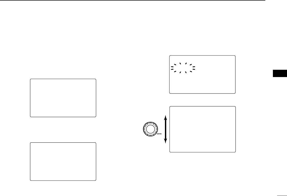
45
6
DSC OPERATION
New2001
6
■Received messages
The transceiver automatically stores up to 20 distress mes-
sages and 20 other messages. The messages can be used
as an assistance to the logbook.
qPush [MENU] to enter the DSC menu.
wRotate [DIAL] to select “RReecceeiivveedd CCaallllss,” push
[DIAL•ENTER].
DDDistress message
qRotate [DIAL] to select “DDiissttrreessss,” push
[DIAL•ENTER].
wRotate [DIAL] to scroll to the desired message, push
[DIAL•ENTER].
• Messages which are blinking have not read.
eRotate [DIAL] to scroll the message.
rPush [CLR] to exit the condition or push [CLR] for 1 sec.
to delete the displayed message and returns to DSC
menu.
--DSC Menu--
Distress
<John
Explosion
LAT:12
°
34.567N
LON:123
°
45.678W
UTC:12:15
DISTANCE:100.8nm
BEARING:12.25
°
<CLR˘Exit/CLR 1s˘Del>
Rotate
--DSC Menu--
Select Message
˘12:15 John
04:43 George
<CLR˘Exit / ENT˘OK>
--DSC Menu--
Select Message
˘Distress
Other
<CLR˘Exit / ENT˘OK>
--DSC Menu--
Select Item
Position Reply
Position Report
POS Report Reply
Polling Request
Polling Reply
˘Received Calls
!IC-M504.qxd 05.12.28 11:29 AM Page 45 (1,1)

46
6DSC OPERATION
New2001
DDOther messages
qRotate [DIAL] to select “OOtthheerr,” push [DIAL•ENTER].
wRotate [DIAL] to scroll to the desired message, push
[DIAL•ENTER].
• Messages which are blinking have not read.
eRotate [DIAL] to scroll the message.
• The stored message has various information and depending on
the type of distress call.
rPush [CLR] to exit the condition or push [CLR] for 1 sec.
to delete the displayed message and returns to DSC
menu.
--DSC Menu--
Individual Call
<Paul
Routine
F3E simplex
CH 08
<CLR˘Exit/CLR 1s˘Del>
--DSC Menu--
Select Message
˘Individual Call
Group Call
Position Replay
All Ships Call
<CLR˘Exit / ENT˘OK>
˘Individual Call
--DSC Menu--
Select Message
Distress
˘Other
<CLR˘Exit / ENT˘OK>
!IC-M504.qxd 05.12.28 11:29 AM Page 46 (1,1)
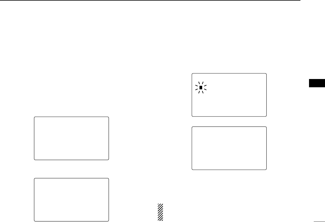
47
6
DSC OPERATION
New2001
6
■DSC Set mode
DDMMSI code check (See p. 16)
DDAdd Individual ID/Group ID (See pgs. 17, 19)
DDDelete Individual ID/Group ID (See pgs. 18, 20)
DDOffset time
This item sets the offset time from the UTC (Universal Time
Coordinated) time.
qPush [MENU] to enter the DSC menu.
wRotate [DIAL] to select “SSeett uupp,” and push
[DIAL•ENTER].
eRotate [DIAL]
to select “OOffffsseett TTiimmee,”
push
[DIAL•ENTER]
.
rSet the offset time from the UTC (Universal Time Coordi-
nated) time with rotating [DIAL].
• Push [16•9] or [CH/WX•DUAL•U/I/C] to move the cursor forward
or backward, respectively.
• Push [CLR] to cancel and exit the condition to the DSC menu.
tPush [DIAL•ENTER] to program and to exit the condition
to the set up menu.
The local time indication is not available when the GPS re-
ceiver (sentence formatter RMC) is connected, the trans-
ceiver’s display indicates UTC time only.
--DSC Menu--
Input Offset Time
+12:00
<CLR<CLR˘ExitExit /ENTENT˘OK>OK>
--DSC Menu--
Input Offset Time
00:00
<CLR<CLR˘ExitExit /ENTENT˘OK>OK>
No offset time (default)
+12 hours
--DSC Menu--
Select Item
Add:INDV ID
Add:Group ID
DEL:INDV ID
DEL:Group ID
˘Offset Time
MMSI Check
--DSC Menu--
Select Item
POS Report Reply
Polling Request
Polling Reply
Received Calls
Distress Setting
˘Set up
!IC-M504.qxd 05.12.28 11:29 AM Page 47 (1,1)

48
6DSC OPERATION
New2001
DDAutomatic acknowledgement
This item sets the automatic acknowledgement function ON
or OFF.
When a position request, position report or polling request call
is received, transceiver automatically transmits a position re-
quest reply, position report reply or polling reply call, respec-
tively.
qPush [MENU] to enter the DSC menu.
wRotate [DIAL] to select “SSeett uupp,” push [DIAL•ENTER].
eRotate [DIAL]
to select “AAuuttoo AACCKK,”
push
[DIAL•ENTER]
.
rRotate [DIAL]
to turn the
automatic acknowledgement
function ON or OFF
.
tPush [DIAL•ENTER] to set the condition.
• Push [CLR] to cancel and exit the condition to the set up menu.
--DSC Menu--
Auto ACK
˘ON
OFF
<CLR<CLR˘ExitExit /ENTENT˘OK>OK>
--DSC Menu--
Select Item
Add:Group ID
DEL:INDV ID
DEL:Group ID
Offset Time
MMSI Check
˘Auto ACK
--DSC Menu--
Select Item
POS Report Reply
Polling Request
Polling Reply
Received Calls
Distress Setting
˘Set up
!IC-M504.qxd 05.12.28 11:29 AM Page 48 (1,1)

49
6
DSC OPERATION
New2001
6
DDNMEA Output
Select the NMEA Output function OFF, All station or List sta-
tion.
When receiving position acknowledgment, transceiver out-
puts it to the external equipment via the NMEA connector.
qPush [MENU] to enter the DSC menu.
wRotate [DIAL] to select “SSeett uupp,” push [DIAL•ENTER].
eRotate [DIAL]
to select “NNMMEEAA OOuuttppuutt,”
push
[DIAL•ENTER]
.
rRotate [DIAL]
to s
elect the NMEA Output function OFF, All
station or List station.
• List Station : Outputs the position data from the specified vessels
listed on the DSC individual ID screen.
• All Station : Outputs the position data from all vessels.
• OFF : No outputs any position data to external equipment.
tPush [DIAL•ENTER] to set the condition.
• Push [CLR] to cancel and exit the condition to the set up menu.
--DSC Menu--
NMEA Output
˘List Station
All Station
OFF
<CLR<CLR˘ExitExit /ENTENT˘OK>OK>
--DSC Menu--
Select Item
DEL:INDV ID
DEL:Group ID
Offset Time
MMSI Check
Auto ACK
˘NMEA Output
--DSC Menu--
Select Item
POS Report Reply
Polling Request
Polling Reply
Received Calls
Distress Setting
˘Set up
!IC-M504.qxd 05.12.28 11:29 AM Page 49 (1,1)
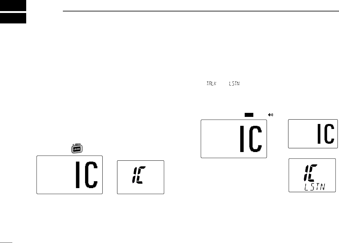
50
OTHER FUNCTIONS
New2001
7
■Intercom operation
The optional Intercom function allows you to talk to the deck
from the cabin. The optional command microphone is
required for Intercom operation.
Connect an optional command microphone as described on
p. 63.
• Transmitting is impossible during Intercom operation.
• The received signal is muted during Intercom operation.
qPush and hold [LO/DX•IC•SCRM] for 1 sec. to enter Inter-
com mode.
• The optional command microphone power is automatically
turned ON, even if the power is OFF.
wPush and hold [LO/DX•IC•SCRM] for 1 sec. again to call
up the optional command microphone side.
• The transceiver and the optional command microphone emit call
beeps.
ePush and hold [PTT] and speak at a normal voice level
into the microphone.
•“
TTAALLKK” or “LLIISSTTEENN”* appears on the caller or listener function
display, respectively.
* “ ” or “ ” appears on the HM-157.
• To adjust the IC-M504’s speaker output level, rotate [VOL].
• To adjust the HM-162’s speaker output level, rotate [SELEC-
TOR] on the HM-162.
• To adjust the HM-157’s speaker output level, push [Y]or [Z]
after pushing [VOL• PA/RX ]on the HM-157.
rAfter releasing [PTT] you can hear the response through
the speaker.
tTo return to the normal operation, push [LO/DX•IC•SCRM]
momentarily.
•[16•9] and [DISTRESS] keys are also available.
INTERCOMINTERCOM
TALKTALK
IC-M504 (caller)
HM-157 (listener)
INTERCOMINTERCOM
LISTENLISTEN
HM-162 (listener)
DIM
INTERCOMINTERCOM
IC-M504/HM-162 HM-157
Push and hold for 1 sec.
!IC-M504.qxd 05.12.28 11:30 AM Page 50 (1,1)
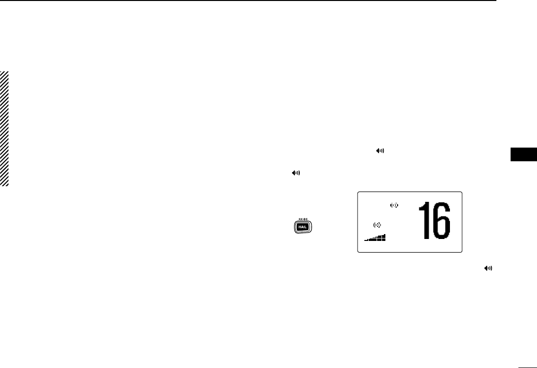
51
7
OTHER FUNCTIONS
New2001
7
• While in the Intercom mode, the transceiver functions
(transmit and receive) are interrupted. If the transceiver
is in transmit condition, the Intercom function is not avail-
able.
• When a DSC call is received, the intercom function is in-
terrupted with an automatic return to the transceiver
mode. The transceiver’s display indicates ‘Receiving
DSC calls.’ (p. 41)
• When a WX alert is received, “WWXX AALLEERRTT” blinks and a
beep sounds. The WX alert sounds after the Intercom
use is finished.
■RX Speaker function
The IC-M504 has an RX Speaker function. When this func-
tion is turned ON, the received audio can be heard on the
deck or tower via an external speaker or hailer speaker.
Connect an external speaker or hailer speaker as described
on p. 58.
qPush and hold [HAIL•RX ] for 1 sec. to enter the RX
Speaker mode.
•“
RRXX” appears
• To adjust the audio output level, rotate [DIAL].
wTo return to normal operation, push and hold [HAIL•RX ]
for 1 sec.
25W25W INTINT
RXRX
TAGTAG
RXRX
1515
<ENT<ENT˘OK>OK> CALLINGCALLING
Push and hold
for 1 sec.
!IC-M504.qxd 05.12.28 11:30 AM Page 51 (1,1)

52
7OTHER FUNCTIONS
New2001
■Hailer operation
The IC-M504 has a 2-way hailer function for voice amplifica-
tion and reception over a loudspeaker, making it unnecessary
to leave the bridge to hear a hailing party.
Connect an external hailer speaker (25 W nominal at
13.8 V/4 Ω) as described on p. 58.
• Transmitting is not possible during hailer operation.
• The received signal is muted during hailer operation.
qPush [HAIL•RX ] to enter hailer mode.
wPush and hold [PTT] and speak at a normal voice level
into the microphone.
•“
TTAALLKK” or “LLIISSTTEENN” appears on the caller or listener function
display, respectively.
• To adjust the hailer level , rotate [DIAL].
eAfter releasing [PTT] you can hear the response through
the speaker.
rTo return to normal operation, push [CLR] or [HAIL•RX ].
• While in the hailer mode, the transceiver functions (trans-
mit and receive) are interrupted. If the transceiver is in
transmit condition, the hailer function is not available.
• When a DSC call is received, the hailer function is inter-
rupted with an automatic return to the transceiver mode.
The transceiver’s display indicates ‘Receiving DSC calls.’
(p. 41)
HAILERHAILER
1515
Push
!IC-M504.qxd 05.12.28 11:30 AM Page 52 (1,1)
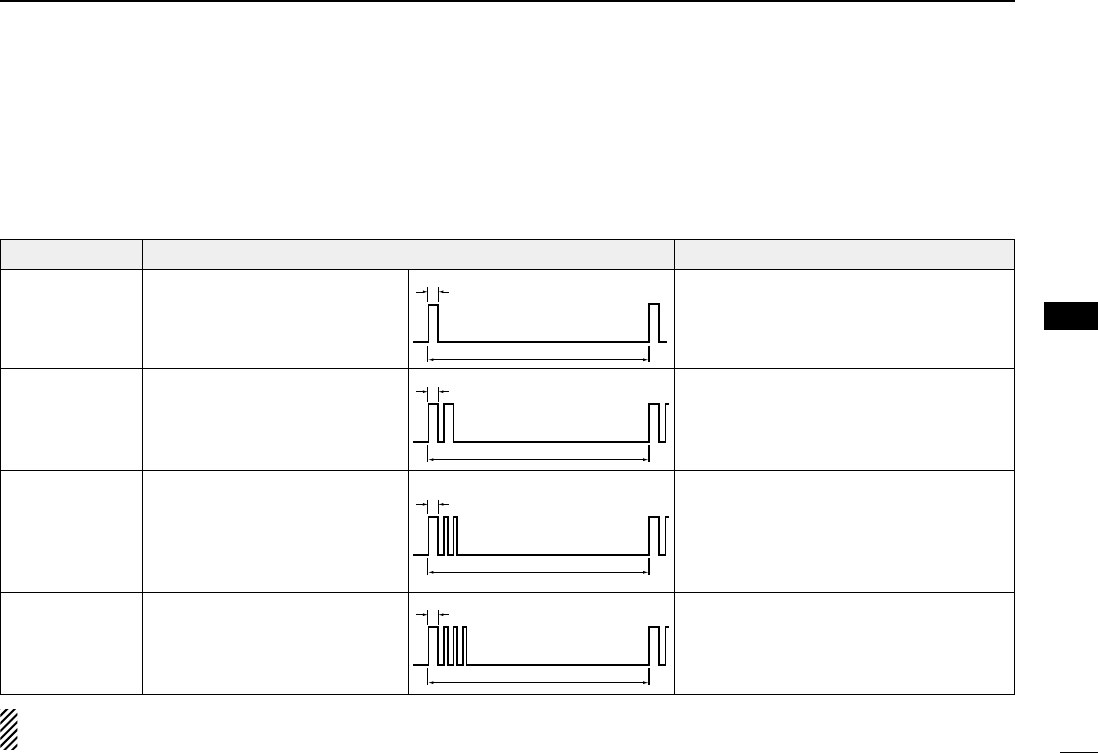
53
7
OTHER FUNCTIONS
New2001
7
■Automatic foghorn function
The automatic foghorn function sounds a horn repeatedly
until the function is turned OFF. Four patterns are available
for varying conditions.
The foghorn outputs from the hailer speaker. To use this func-
tion, the hailer speaker must be connected to the transceiver.
See p. 58 for connection details.
TYPE PATTERN USAGE
UNDERWAY
STOP
SAIL
TOW
The audio frequency of the foghorn is selectable. See
p. 57 for details on selecting the audio frequency.
One 5-second blasts every 120
seconds.
Two 5-second blasts (separated
by 2 seconds) every 120 seconds.
One 5-second blast followed by
two 1-second blasts (each sepa-
rated by 2 seconds) every 120
seconds.
One 5-second blast followed by
three 1-second blasts (each sep-
arated by 2-seconds) every 120
seconds.
Motor vessel underway and making way.
Motor vessel underway but stopped (not
making way).
Sailing vessel underway, fishing vessel
(underway or anchored), vessel not under
command, a vessel restricted in her ability
to maneuver (underway or at anchor), or a
vessel towing or pushing another ahead.
Vessel under tow (manned).
5s±1
120s
5s±1
2s
1s
120s
5s±1
2s
1s
120s
5s±1
2s 120s
!IC-M504.qxd 05.12.28 11:30 AM Page 53 (1,1)
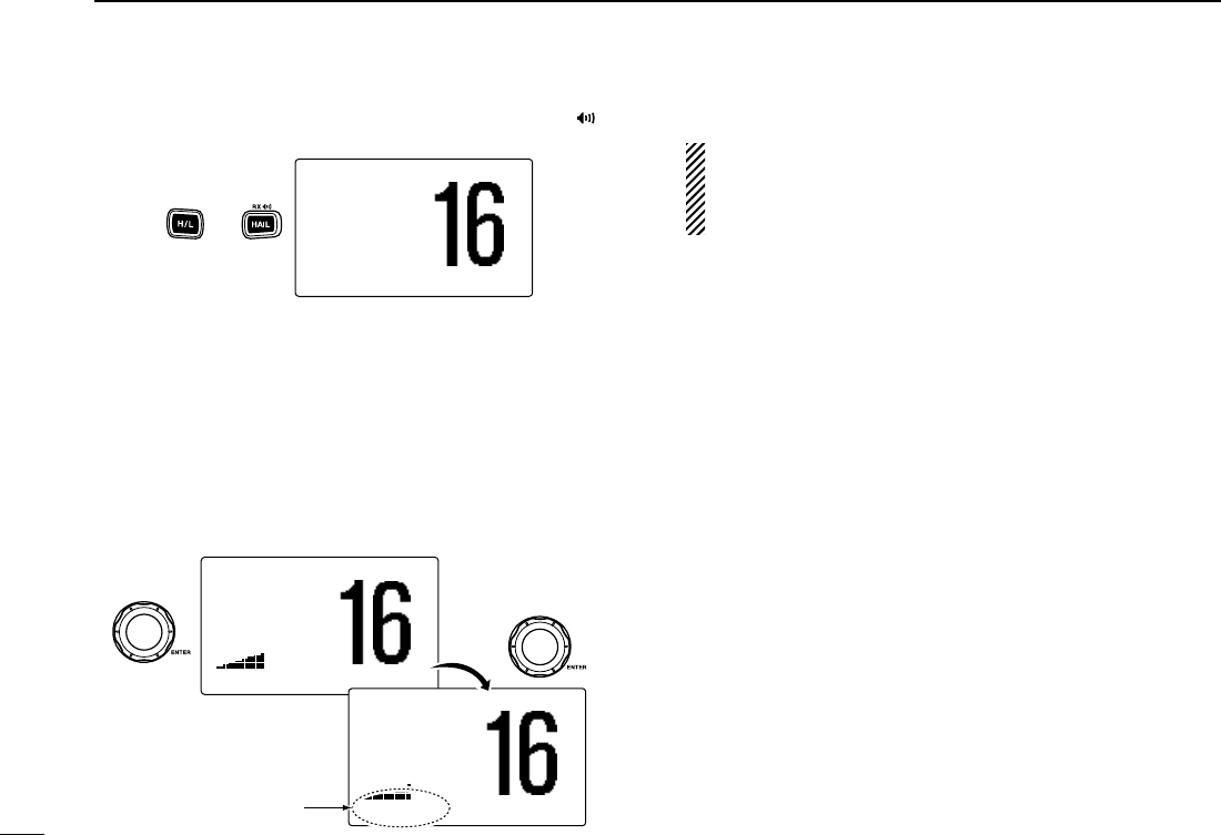
54
7OTHER FUNCTIONS
New2001
qWhile pushing and holding [H/L], push [HAIL•RX ] to
enter auto foghorn mode.
wRotate [DIAL] to select the desired foghorn pattern, push
[DIAL•ENTER].
•‘
UUNNDDEERRWWAAYY,’ ‘SSTTOOPP,’ ‘SSAAIILL,’ ‘TTOOWW’ are available. (p. 53)
• Even if [DIAL•ENTER] hasn’t been pushed, the display auto-
matically changes to the next step after 2 sec. of inactivity.
eRotate [DIAL] to adjust the foghorn level, push
[DIAL•ENTER].
• The foghorn level is adjustable in 30 steps.
• Even if [ENT] hasn’t been pushed, the display automatically
changes to the next step after 2 sec. of inactivity.
r
To return to normal operation, repeat step q.
When a DSC call is received, the automatic foghorn func-
tion is interrupted with an automatic return to the trans-
ceiver mode. The transceiver’s display indicates ‘Receiv-
ing DSC calls.’ (p. 41)
25W25W INTINT
TAGTAG
FOGHORNFOGHORN
1515
<ENT<ENT˘OK>OK> CALLINGCALLING
Rotate
Push
25W25W INTINT
TAGTAG
FOGHORNFOGHORN
1515
UNDERWAYUNDERWAY CALLINGCALLING
The selected foghorn
pattern is displayed.
25W25W INTINT
TAGTAG
˘UNDERWAYUNDERWAY
STOPSTOP
<ENT<ENT˘OK>OK> CALLINGCALLING
Push and
!IC-M504.qxd 05.12.28 11:30 AM Page 54 (1,1)
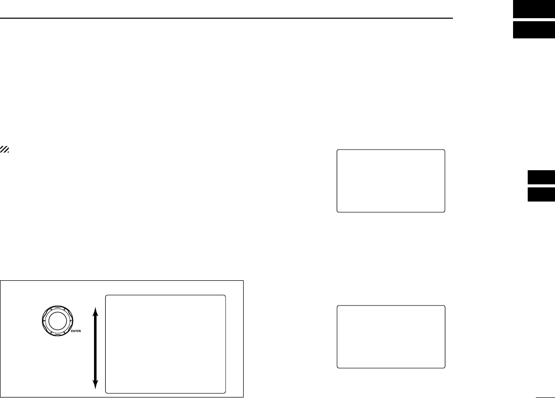
55
8
SET MODE
7
8
■Set mode programming
Set mode is used to change the conditions of the transceiver’s
functions: Scan type, Scan resume timer, Weather alert,
Dual/Tri-watch, Beep tone, LCD contrast, Automatic foghorn fre-
quency, Radio power, Scrambler type* and Scrambler code.*
*Appears only when the optional scrambler unit is installed.
Available functions may differ depending on dealer setting.
qTurn power OFF.
wWhile pushing and holding [16•9], turn power ON to enter
Set mode.
eAfter the display appears, release [16•9].
rRotate [DIAL] to select the desired item, push
[DIAL•ENTER].
tRotate [DIAL] to select the desired condition of the item.
yPush [CLR], or rotate [DIAL] to select “EExxiitt,” then push
[DIAL•ENTER] to exit set mode and returns to normal op-
eration condition.
■Set mode items
DScan type
The transceiver has 2 scan types: Normal scan and Priority
scan. Normal scan searches all TAG channels in the selected
channel group. Priority scan searches all TAG channels in se-
quence while monitoring Channel 16.
DDScan resume timer
The scan resume timer can be selected as a pause (OFF) or
timer scan (ON). When OFF is selected, the scan pauses
until the signal disappears. When ON is selected, the scan
pauses 5 sec. and resumes even if a signal has been re-
ceived on any other channel than Channel 16.
--Set Mode--
Scan Timer
ON
˘OFF
<ENT˘OK>
Default: OFF
--Set Mode--
Scan-Type
Priority
˘Normal
<ENT˘OK>
Default: Normal
Rotate
--Set Mode--
˘Scan Type
Scan Timer
WX Alert
Dual/Tri
Beep
Contrast
Foghorn Frequency
Radio Power
Scrambler Type
Scrambler Code
Exit
•SET MODE CONSTRUCTION
!IC-M504.qxd 05.12.28 11:30 AM Page 55 (1,1)

56
8SET MODE
New2001
DDWeather alert
A NOAA broadcast station transmits a weather alert tone be-
fore important weather information.
When “OONN” is selected, the previously selected (used) weather
channel is checked any time during standby or while scanning.
When “OONN wwiitthh WWXX SSCCAANN” is selected, the weather chan-
nels are checked in sequence during standby or while scan-
ning.
The “WWXX AALLEERRTT” indicator blinks until the transceiver is op-
erated after the transceiver detects the alert.
•“
WWXX AALLEERRTT” appears instead of “WWXX” indication when the function
is set ON.
DDDual/Tri-watch
This item can be selected as Dualwatch or Tri-watch. (p. 14)
.DDBeep tone
You can select the silent operation by turning beep tones OFF
or you can have confirmation beeps sound at the push of a
key by turning beep tones ON.
DDLCD contrast
The LCD contrast can be adjustable in 8 levels. The level 1 is
the lowest contrast, and the level 8 is the highest contrast.
--Set Mode--
Contrast
˘5
4
3
2
1
<ENT˘OK>
Default: 5
--Set Mode--
Beep
˘ON
OFF
<ENT˘OK>
Default: ON
--Set--Set Mode--
Dual/TriDual/Tri
Tri-watchTri-watch
˘Dualwatch
<ENT<ENT˘OK>
Default: Dualwatch
--Set--Set Mode--
WX Alert
ON
ON with WXWX SCAN
˘OFF
<ENT<ENT˘OK>
Default: OFF
!IC-M504.qxd 05.12.28 11:30 AM Page 56 (1,1)

57
8
SET MODE
New2001
8
DDAutomatic foghorn frequency
The audio frequency of the automatic foghorn can be ad-
justed to suit your preference. While this item is selected,
pushing [PTT] outputs the foghorn— experiment with the fre-
quencies available until you find one you like.
• Available frequency range is 200 Hz to 850Hz in 50 Hz step.
DDRadio power
This item sets the Radio Power function ON or OFF.
ON : The transceiver’s power is controlled by the optional
command microphone. When the command micro-
phone is turned OFF, the transceiver will also be turned
OFF automatically.
OFF : The transceiver’s power is not controlled by the optional
command microphone. Even if the command microphone
is turned OFF, the transceiver will continue to work.
DDScrambler type
(Appears when a scrambler unit is installed)
When an optional scrambler unit is installed, the scrambler
type can be selected in set mode depending on dealer setting.
DDScrambler code
(Appears when a scrambler unit is installed)
When an optional scrambler unit is installed, the scrambler
code can be set depending on dealer setting.
When the UT-112 is installed, 32 codes (1 to 32) can be se-
lected.
When the UT-98 is installed, 128 codes (0 to 127) can be se-
lected.
--Set Mode--
Scrambler Code
5
4
3
2
˘1
<ENT˘OK>
--Set Mode--
Scrambler Code
4
3
2
1
˘0
<ENT˘OK>
Default: 0
(When UT-98 is installed)
Default: 1
(When UT-112 is installed)
--Set Mode--
Scrambler Type
UT-98
˘UT-112
<ENT˘OK>
Default: UT-112
--Set Mode--
Radio Power
˘ON
OFF
<ENT˘OK>
Default: ON
--Set Mode--
FoghornFoghorn FrequencyFrequency
˘400
350
300
250
200
<ENT˘OK>
Default: 400
!IC-M504.qxd 05.12.28 11:30 AM Page 57 (1,1)
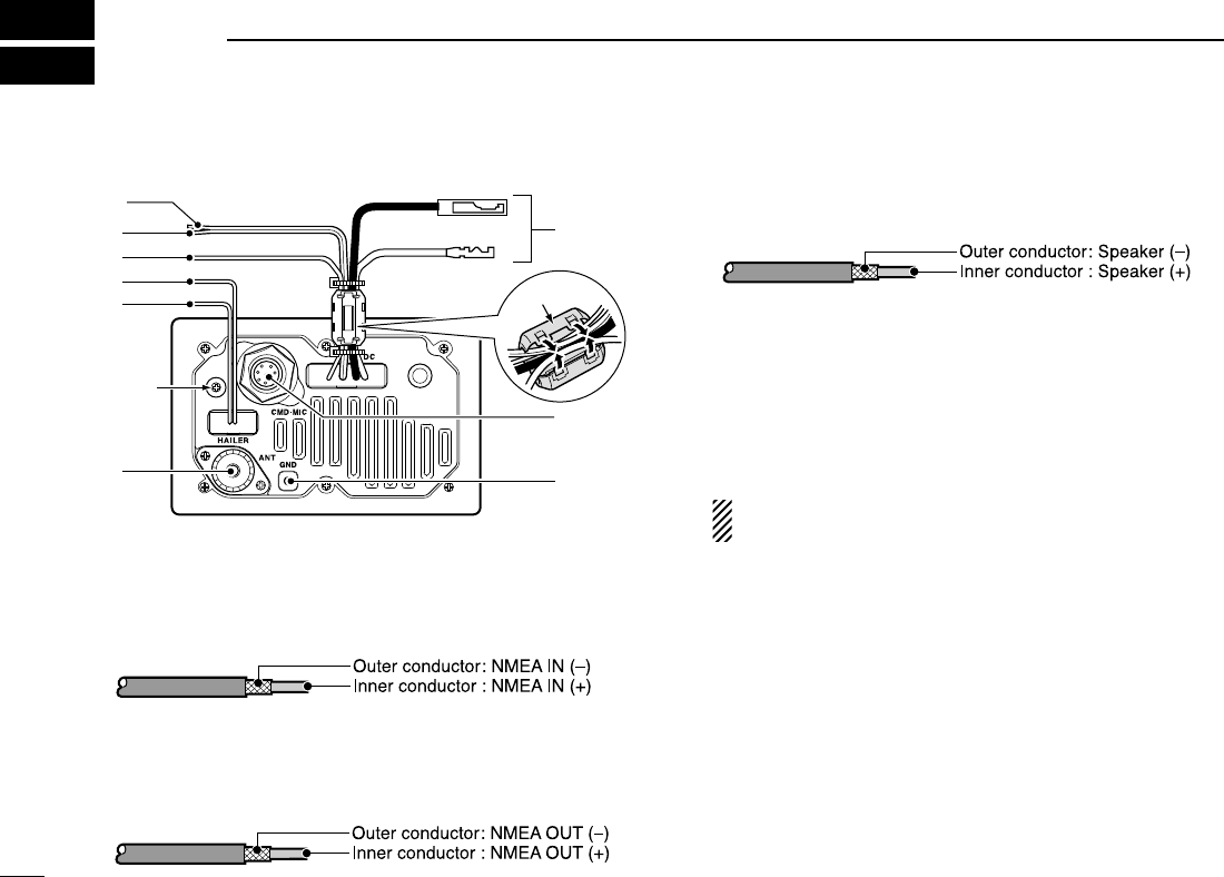
58
CONNECTIONS AND MAINTENANCE
New2001
9
■Connections
qNMEA IN LEAD (Red)
Connects to a GPS receiver for position indication.
• A NMEA0183 ver. 2.0 or 3.01 (sentence formatters RMC, GGA,
GNS, GLL) compatible GPS receiver is required. Ask your dealer
about suitable GPS receivers.
wNMEA OUT LEAD (White)
Connects to a PC or navigation equipment (NMEA0183
ver. 3.01 sentence formatters DSC, DSE compatible) for
position data received from other ships.
eEXTERNAL SPEAKER LEAD (Yellow)
Connects to an external speaker.
rHAILER/FOGHORN (–) LEAD (Black)
Connects to a hailer speaker (25 W nominal at 13.8 V/4 Ω).
tHAILER/FOGHORN (+) LEAD (Blue)
Connects to a hailer speaker (25 W nominal at 13.8 V/4 Ω).
yANTENNA CONNECTOR
Connects a marine VHF antenna with a PL-259 connector
to the transceiver.
CAUTION: Transmitting without an antenna may dam-
age the transceiver.
uGROUND TERMINAL
Connect this terminal to a vessel ground to prevent electri-
cal shocks and interference from other equipment occur-
ring. Use an self-tapping screw (3 ×8 mm.)
iEXTERNAL MICROPHONE JACK
Connects to optional command microphone.
oDC POWER CONNECTOR
Connects the supplied DC power cable from this connector
to an external 12 V battery.
Do not
loose!
o
r
t
y
i
w
q
e
u
Ferrite core*
!IC-M504.qxd 05.12.28 11:30 AM Page 58 (1,1)
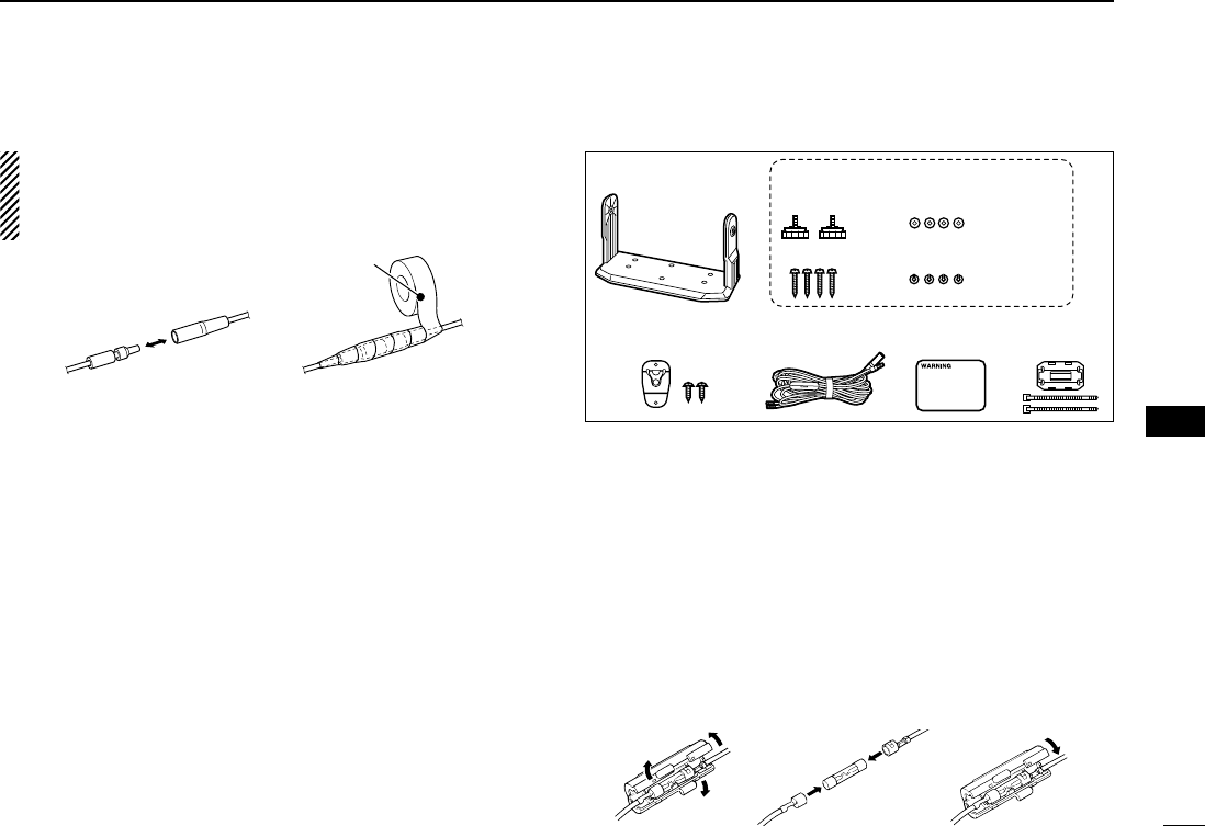
59
9
CONNECTIONS AND MAINTENANCE
New2001
9
CAUTION: After connecting the DC power cable, NMEA
IN/OUT leads, external speaker lead and hailer lead, cover
the connector and leads with an adhesive tape as shown
below, to prevent water seeping into the transceiver.
* The supplied ferrite core must be attached to the NMEA
in/out leads and DC power cables as illustrated at left. Fix
the ferrite core near the transceiver with the two supplied
ties to prevent it from moving.
■Supplied accessories
■Antenna
A key element in the performance of any communication sys-
tem is the antenna. Ask your dealer about antennas and the
best place to mount them.
■Fuse replacement
One fuse is installed in the supplied DC power cable. If a fuse
blows or the transceiver stops functioning, track down the
source of the problem, if possible, and replace the damaged
fuse with a new one of the proper rating.
Fuse rating: 10 A
Mounting bracket For mounting bracket
DC power cable
(OPC-891)
Microphone hanger
and screws (3×16)
Knob bolts
Screws (5×20)
Flat washers (M5)
Spring washers (M5)
Warning
sticker
Ferrite core
and ties
Rubber vulcanizing
tape
!IC-M504.qxd 05.12.28 11:30 AM Page 59 (1,1)
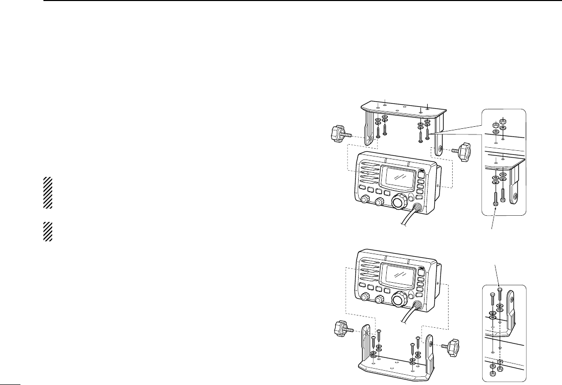
60
9CONNECTIONS AND MAINTENANCE
New2001
■Mounting the transceiver
DDUsing the supplied mounting bracket
The universal mounting bracket supplied with your transceiver
allows overhead or dashboard mounting.
• Mount the transceiver securely with the 4 supplied screws
(5 ×20) to a surface which is more than 10 mm thick and
can support more than 5 kg.
• Mount the transceiver so that the face of the transceiver is at
90° to your line of sight when operating it.
CAUTION: KEEP the transceiver and microphone at least
1 meter away from your vessel’s magnetic navigation com-
pass.
NOTE: Check the installation angle; the function display
may not be easy-to-read at some angles.
• OVERHEAD MOUNTING
• MOUNTING ON THE BOARD These screws are shown
as mounting example only.
Not supplied with acces-
sories.
!IC-M504.qxd 05.12.28 11:30 AM Page 60 (1,1)
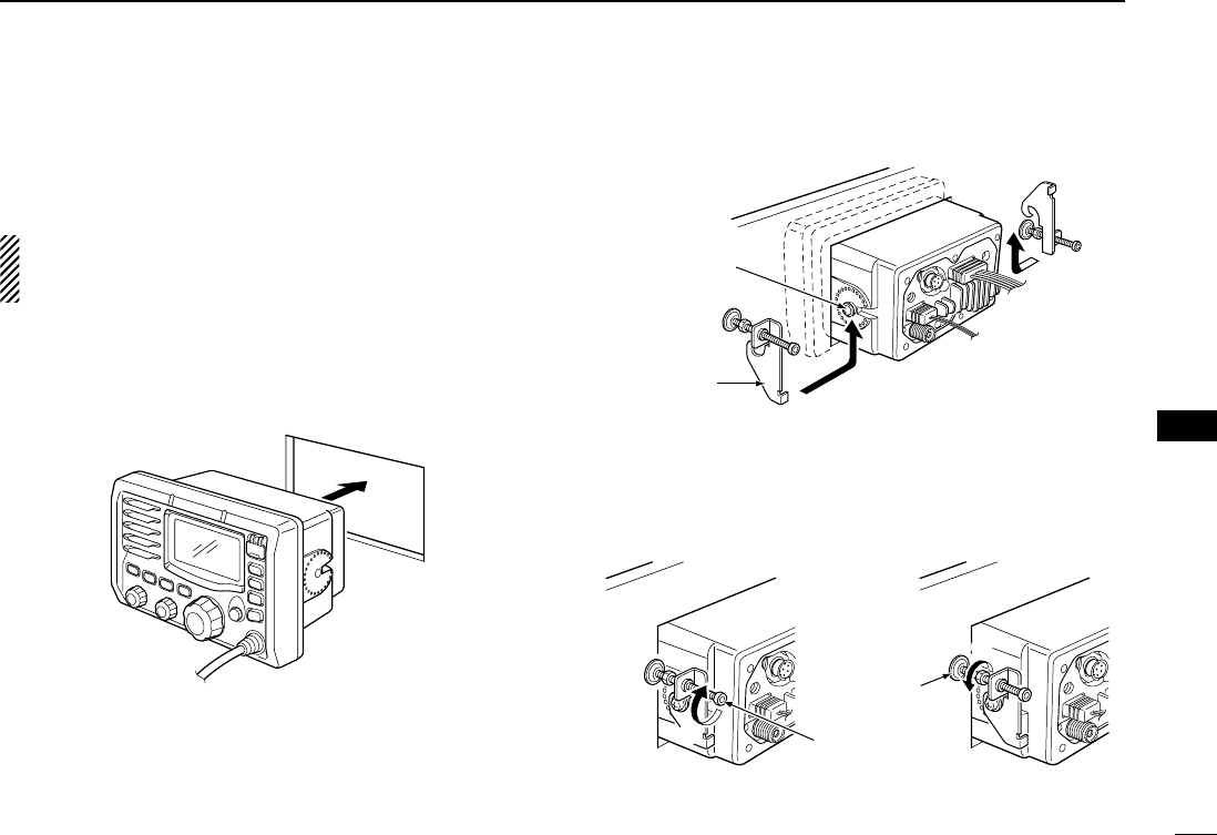
61
9
CONNECTIONS AND MAINTENANCE
New2001
9
■MB-75 installation
An optional MB-75 FLUSH MOUNT is available for mounting
the transceiver to a flat surface such as an instrument panel.
CAUTION: KEEP the transceiver and microphone at least
1 meter away from your vessel’s magnetic navigation com-
pass.
qUsing the template on the last page, carefully cut a hole
into the instrument panel (or wherever you plan to mount
the transceiver).
wSlide the transceiver through the hole as shown below.
eAttach the 2 supplied bolts (M5 ×8 mm) on either side of
the IC-M504.
rAttach the clamps on either side of the IC-M504.
• Make sure that the clamps align parallel to the IC-M504’s body.
tTighten the end bolts on the clamps (rotate clockwise) so
that the clamps press firmly against the inside of the in-
strument control panel.
yTighten the locking nuts (rotate counterclockwise) so that
the IC-M504 is securely mounted in position as below.
uConnect the antenna and power cable, then return the in-
strument control panel to its original place.
t
y
End bolt
Locking nut
r
r
Clamp
Supplied bolt
!IC-M504.qxd 05.12.28 11:30 AM Page 61 (1,1)
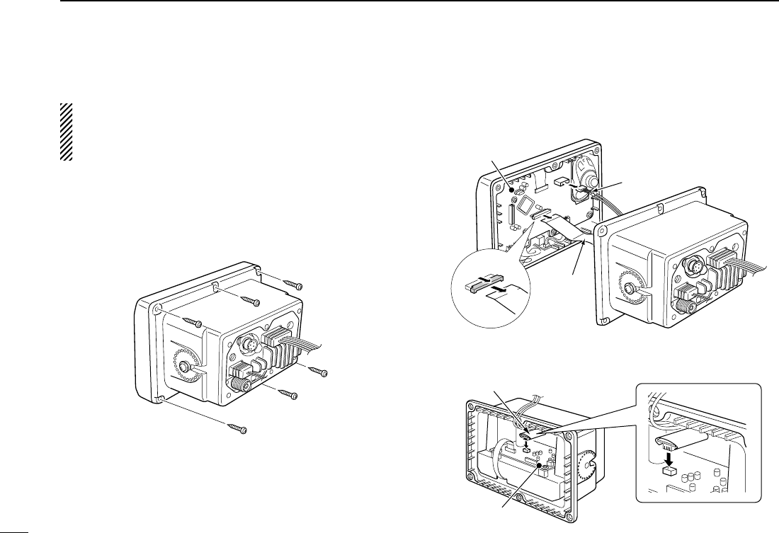
62
9CONNECTIONS AND MAINTENANCE
New2001
■UT-98/UT-112 installation
CAUTION: DISCONNECT the DC power cable from the
transceiver before performing any work on the transceiver.
Otherwise, there is danger of electric shock and/or equip-
ment damage.
Follow the case opening procedure shown here when you
want to install an optional scrambler unit.
qRemove the 6 screws as shown below and open the
transceiver.
wDisconnect the flat cable and NMEA (4 pin) from J5 of the
LOGIC unit.
eInstall an optional unit (UT-98 or UT-112) to J3 on the AF
unit as shown below.
Optional unit
AF unit
q
LOGIC unit
NMEA (4 pin)
Flat cable
w
!IC-M504.qxd 05.12.28 11:30 AM Page 62 (1,1)
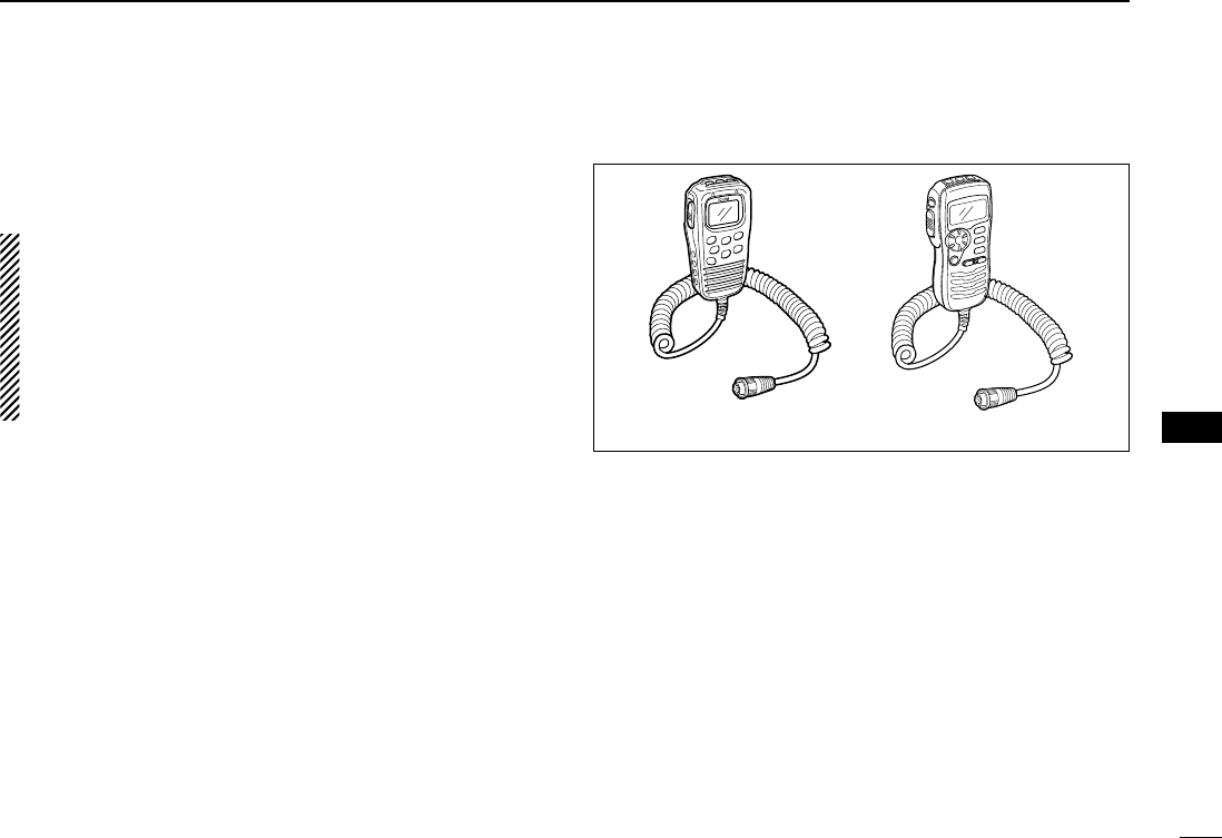
63
9
CONNECTIONS AND MAINTENANCE
New2001
9
rReturn the cables and screws to the original position.
• Be sure not upside down the flat cable.
CAUTION:
• When re-assembling the case and tightening the screws,
you must keep the specified torque (0.7±0.1 N.m). Oth-
erwise the transceiver may be damaged (torque too high)
or lose waterproof efficiency (torque too low).
• When uninstalling the optional unit, remove it vertically.
Wiggling the unit from side to side may damage the op-
tional unit's connector.
■HM-157/HM-162 installation
The optional HM-157/HM-162 can be connected to the trans-
ceiver directly, as well as via the supplied connection cable
for longer distance remote operation. The connector of the
connection cable can be installed into a cabinet, wall, etc., as
a built-in plug.
For longer distance remote operation, the optional extension
cable, OPC-999/OPC-1541* (6 m; 20 ft/connecting between
transceiver and the connection cable), is available, and up to
two OPC-999/OPC-1541* can be added.
*OPC-999 : For the HM-157
OPC-1541 : For the HM-162
Do not connect the HM-162 to the OPC-999, and the HM-
157 to the OPC-1541.
HM-157 HM-162
!IC-M504.qxd 05.12.28 11:30 AM Page 63 (1,1)
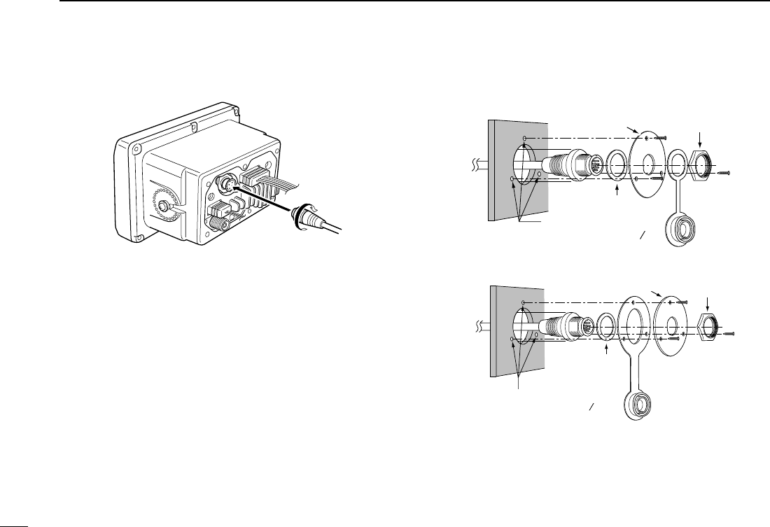
64
9CONNECTIONS AND MAINTENANCE
New2001
qInsert the supplied cable into the external microphone jack
and tighten the cable nut as shown below.
wTo use the supplied cable as a wall socket, follow the
below steps.
eUsing the mounting base, carefully mark off the two spots
where the cable and screws will be fastened.
rDrill holes at these marks.
tInstall the mounting base using the supplied screws as
shown below.
• HM-157
• HM-162
Gasket
Cap
Mounting base Nut
Screw holes
(approx. 2 (d) mm; 3 32″)
Gasket
Cap
Mounting base Nut
Screw holes
(approx. 2 (d) mm; 3 32″)
!IC-M504.qxd 05.12.28 11:30 AM Page 64 (1,1)

65
9
CONNECTIONS AND MAINTENANCE
New2001
9
yThe completed installation should look like this.
• HM-157
• HM-162
!IC-M504.qxd 05.12.28 11:30 AM Page 65 (1,1)
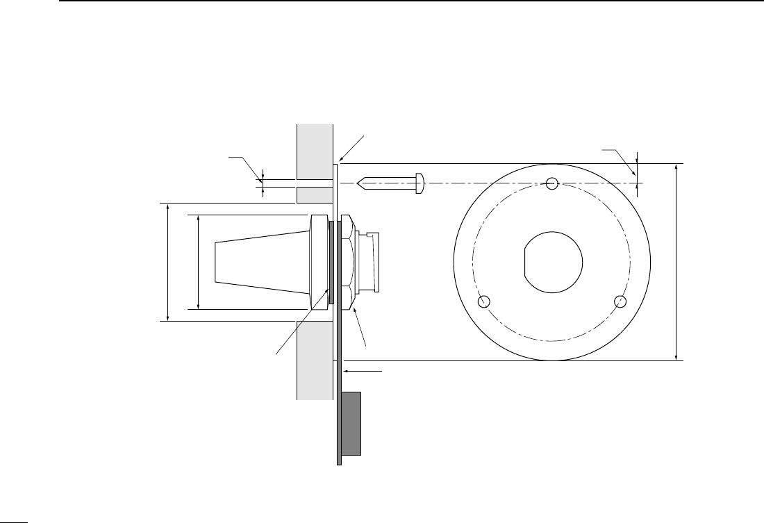
66
9CONNECTIONS AND MAINTENANCE
New2001
50 (d) mm; 131⁄32˝
23 (d) mm; 29⁄32˝
24 to 27 (d) mm
(15⁄16 to 11⁄16˝)
5 mm; 3⁄16˝
Gasket
Mounting base
Cap
Nut
2 mm; 3⁄32˝
!IC-M504.qxd 05.12.28 11:30 AM Page 66 (1,1)

67
10
TROUBLESHOOTING
9
10
PROBLEM POSSIBLE CAUSE SOLUTION REF.
No sound from speaker. • Squelch level is too high.
• Volume level is too low.
• Speaker has been exposed to water.
p. 8
p. 8
—
• Set [SQL] to the threshold point.
• Set [VOL] to a suitable level.
• Drain water from the speaker.
The transceiver does
not turn ON.
• Bad connection to the power supply. p. 58• Check the connection to the transceiver.
Transmitting is impossi-
ble, or high power can
not be selected.
• Some channels are for low power or re-
ceive only.
• The output power is set to low.
pgs. 6,
7, 70
p. 8
• Change channels.
• Push [H/L] to select high power.
Scan does not start. • TAG channel is not programmed. • Set the desired channels as TAG channels. p. 13
No beeps. • Beep tones are turned OFF.
• The squelch is open.
• Turn the beep tone ON in Set mode.
• Set [SQL] to the threshold point.
p. 56
p. 8
Distress call cannot be
transmitted.
• MMSI (DSC self ID) code is not pro-
grammed.
• Program the MMSI (DSC self ID) code. p. 15
Sensitivity is low. • The Attenuator is activated. • Push [LO/DX•IC•SCRM] to turn the function
OFF.
p. 8
!IC-M504.qxd 05.12.28 11:30 AM Page 67 (1,1)

68
SPECIFICATIONS AND OPTIONS
New2001
11
■Specifications
DDGeneral
• Frequency coverage : Tx 156.025–157.425 MHz
Rx 156.050–163.275 MHz
• Mode :
FM (16K0G3E), DSC (16K0G2B)
• Channel spacing : 25 kHz
• Current drain (at 13.8 V) : TX high 5.5 A max.
Max. audio 1.5 A max.
• Power supply requirement : 13.8 V DC ±15%
(negative ground)
• Frequency stability : ±10 ppm
(–20°C to +60°C; –4°F to +140°F)
• Antenna impedance : 50 Ωnominal
• Dimensions : 165(W) ×110(H) ×123.2(D) mm
(Projections not included) 6 1⁄2(W) ×4 11⁄32(H) ×4 27⁄32(D) in
• Weight : Approx. 1450 g; 3 lb 19 oz
DDTransmitter
• Output power : 25 W/1 W
• Modulation system : Variable reactance frequency
modulation
• Max. frequency deviation : ±5.0 kHz
• Spurious emissions : Less than 70 dBc
DDReceiver
• Receive system : Double conversion
superheterodyne
• Sensitivity (12 dB SINAD) : 0.22 µV (typical)
• Squelch sensitivity : Less than 0.32 µV
• Intermodulation rejection ratio : More than 80 dB
•
Spurious response rejection ratio
: More than 80 dB
• Adjacent channel selectivity : More than 80 dB
• Audio output power : 4.5 W (typical) at 10% distortion
with a 4 Ωload
All stated specifications are subject to change without notice or
obligation.
!IC-M504.qxd 05.12.28 11:30 AM Page 68 (1,1)
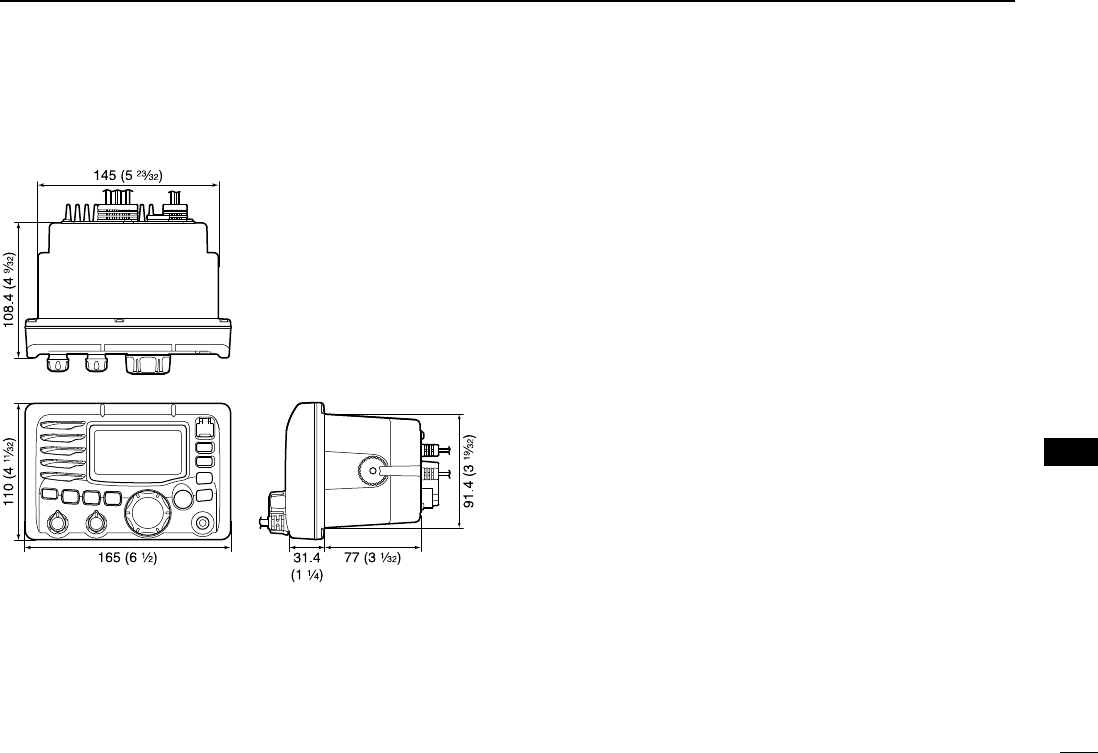
69
11
SPECIFICATIONS AND OPTIONS
New2001
11
DDDimensions
■Options
•MB-75
FLUSH MOUNT KIT
For mounting the transceiver to a panel.
•HM-157
COMMANDMIC II
™
External microphone-type controller. Provides optional inter-
com operation. 6 m (20 feet) microphone cable and mount-
ing base included. Black and white colors are available.
Do not connect the HM-157 to the OPC-1541.
•HM-162
COMMANDMIC III
™
External microphone-type controller. Provides optional inter-
com operation. 6 m (20 feet) microphone cable and mount-
ing base included. Black and white colors are available.
Do not connect the HM-162 to the OPC-999.
•OPC-999
MICROPHONE EXTENSION CABLE
6 m (20 feet) microphone extension cable for optional HM-
157
COMMANDMIC II
™. Up to 2 OPC-999 can be connected.
(18 m; 60 feet maximum)
•OPC-1541
MICROPHONE EXTENSION CABLE
6 m (20 feet) microphone extension cable for optional HM-
162
COMMANDMIC III
™. Up to 2 OPC-1541 can be connected.
(18 m; 60 feet maximum)
•UT-112
VOICE SCRAMBLER UNIT
Ensures private communications. 32 codes are available.
Not available in some countries.
•UT-98
VOICE SCRAMBLER UNIT
Ensures private communications. 128 codes are available.
Not available in some countries.
Unit: mm (inch)
!IC-M504.qxd 05.12.28 11:30 AM Page 69 (1,1)

70
CHANNEL LIST
New2001New2001
12
Channel number
USA CAN
Transmit
Receive
01 156.050 160.650
01A 156.050 156.050
02 156.100 160.700
03 156.150 160.750
03A 156.150 156.150
156.200 160.800
04A 156.200 156.200
156.250 160.850
05A 05A 156.250 156.250
06 06 156.300 156.300
156.350 160.950
07A 07A 156.350 156.350
08 08 156.400 156.400
09 09 156.450 156.450
10 10 156.500 156.500
11 11 156.550 156.550
12 12 156.600 156.600
13
*2
13
*1
156.650 156.650
14 14 156.700 156.700
15
*2
15
*1
156.750 156.750
16 16 156.800 156.800
17
*1
17
*1
156.850 156.850
156.900 161.500
18A 18A 156.900 156.900
Frequency (MHz)
INT
01
02
03
04
05
06
07
08
09
10
11
12
13
14
15
*1
16
17
18
Channel number Frequency (MHz)
USA CAN
Transmit
Receive
19A 19A 156.950 156.950
20 20
*1
157.000 161.600
21 157.050 161.650
21A 21A 157.050 157.050
157.100 161.700
22A 22A 157.100 157.100
23 157.150 161.750
23A 157.150 157.150
24 24 157.200 161.800
25 25 157.250 161.850
26 26 157.300 161.900
27 27 157.350 161.950
28 28 157.400 162.000
60 156.025 160.625
156.075 160.675
61A 61A 156.075 156.075
156.125 160.725
62A 156.125 156.125
156.175 160.775
63A 156.175 156.175
64 156.225 160.825
INT
20
21
22
23
24
25
26
27
28
60
61
62
63
64
20A 157.000 157.000
Channel number
66A
Frequency (MHz)
66A
*1
USA CAN
Transmit
Receive
64A 64A 156.225 156.225
65A 65A 156.275 156.275
156.325 160.925
67
*2
67 156.375 156.375
68 68 156.425 156.425
69 69 156.475 156.475
70
*3
70
*3
156.525 156.525
71 71 156.575 156.575
72 72 156.625 156.625
73 73 156.675 156.675
74 74 156.725 156.725
77
*1
77
*1
156.875 156.875
156.925 161.525
78A 78A 156.925 156.925
156.975 161.575
79A 79A 156.975 156.975
157.025 161.625
80A 80A 157.025 157.025
157.075 161.675
81A 81A 157.075 157.075
157.125 161.725
82A 82A 157.125 157.125
INT
65A
66
67
68
69
70
*3
71
72
73
74
77
78
79
80
81
82
156.325 156.32566A
Channel number
84A
Frequency (MHz)
USA CAN
Transmit
Receive
83A 83A 157.175 157.175
84 84 157.225 161.825
85 85 157.275 161.875
85A 157.275 157.275
86 86 157.325 161.925
86A 157.325 157.325
87 87 157.375 161.975
87A 157.375 157.375
88 88 157.425 162.025
88A 157.425 157.425
INT
84
85
86
87
88
157.225 157.225
WX channel
4
Frequency (MHz)
Transmit Receive
1 RX only 162.550
2 RX only 162.400
3 RX only 162.475
5 RX only 162.450
6 RX only 162.500
7 RX only 162.525
8 RX only 161.650
9 RX only 161.775
10 RX only 163.275
RX only 162.425
*1
Low power only.
*3
DSC operation only
156.950 161.55019
21b Rx only 161.650
25b Rx only 161.850
156.275 160.87565
28b Rx only 162.000
83 157.175 161.77583
83b Rx only 161.775
*2
Momentary high power.
NOTE: Simplex channels, 3, 21, 23, 61, 64, 81, 82 and 83 CANNOT
be lawfully used by the general public in U.S.A. waters.
!IC-M504.qxd 05.12.28 11:30 AM Page 70 (1,1)
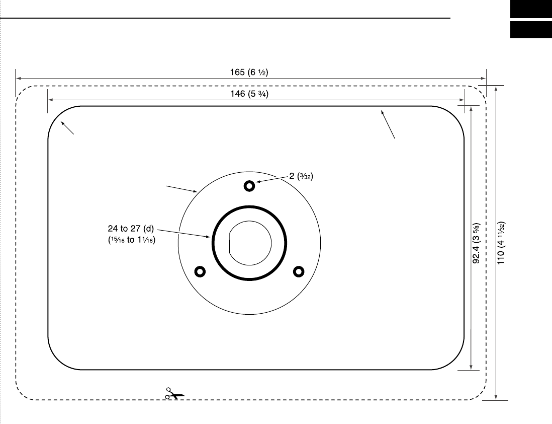
New2001
TEMPLATE
HM-157/
HM-162
Unit: mm (inch)
R12 (Max.)
MB-75
Cut here
!IC-M504.qxd 05.12.28 11:30 AM Page 71 (1,1)
!IC-M504.qxd 05.12.28 11:30 AM Page 72 (1,1)

MEMO
New2001
!IC-M504.qxd 05.12.28 11:30 AM Page 73 (1,1)

1-1-32 Kamiminami, Hirano-ku, Osaka 547-0003, Japan
A-6483H-1US
Printed in Japan
©2006 Icom Inc.
New2001
!IC-M504.qxd 05.12.28 11:30 AM Page 74 (1,1)