ICOM orporated 297000 Scanning Receiver User Manual
ICOM Incorporated Scanning Receiver Users Manual
UserManual.wiki
>
ICOM orporated
>
297000 User Manual
Users Manual
Navigation menu
Upload a User Manual
Namespaces
Wiki Guide
HTML
PDF
Info
Views
User Manual
Discussion / Help
Navigation
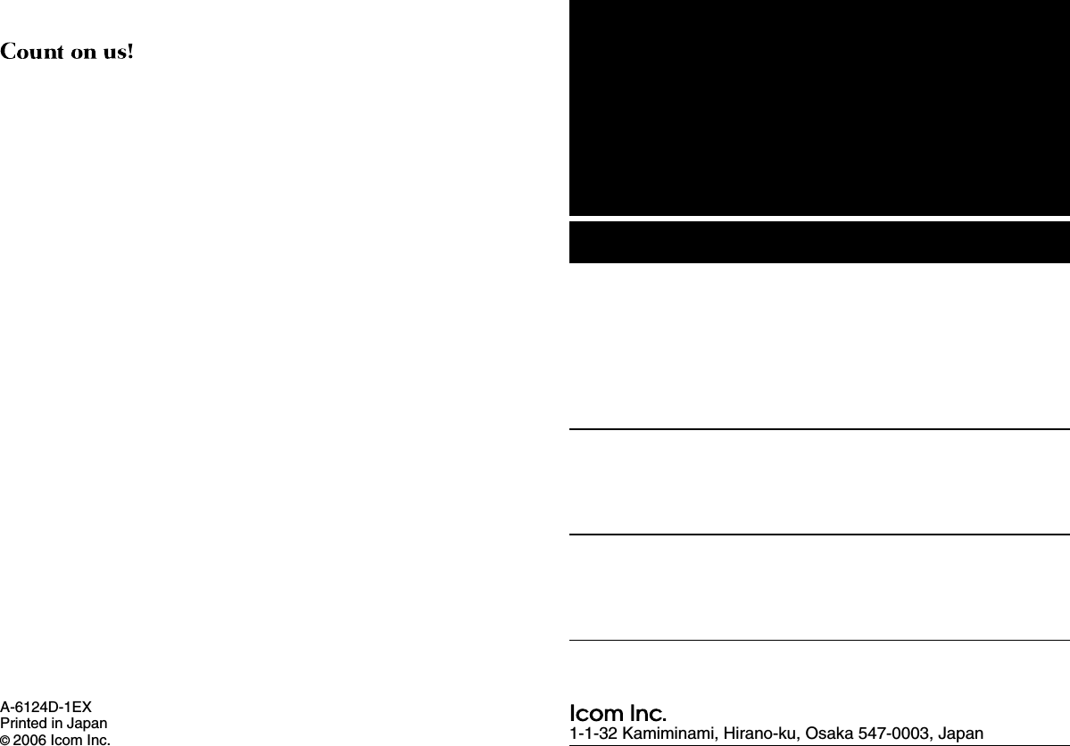
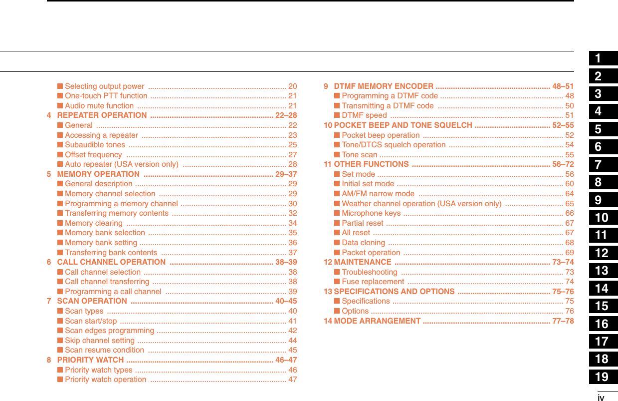
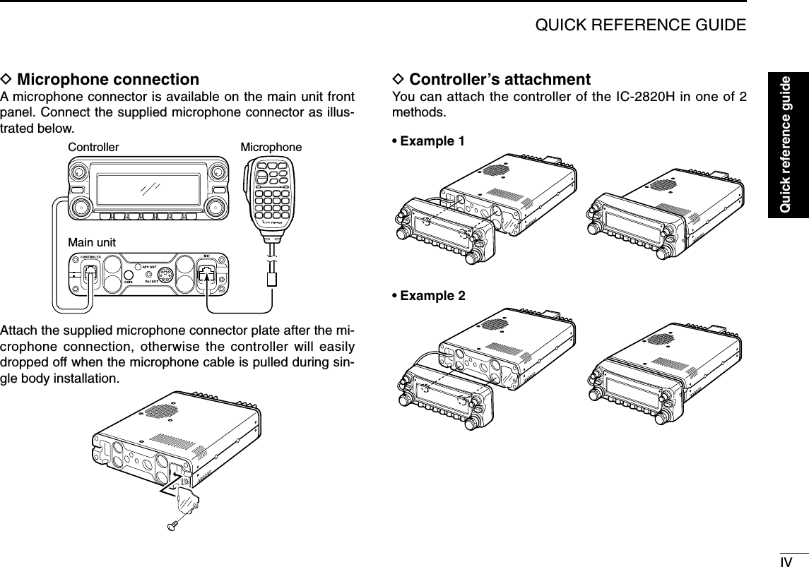
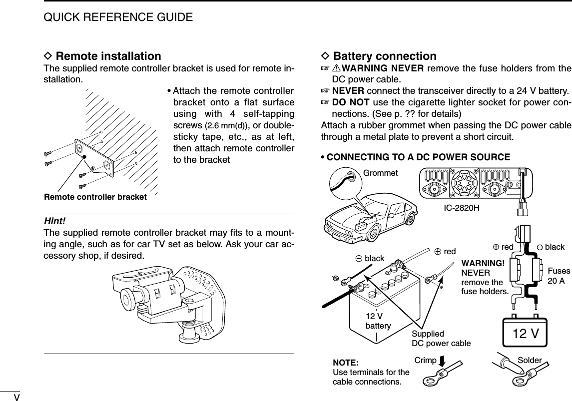
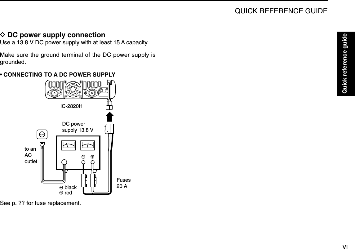
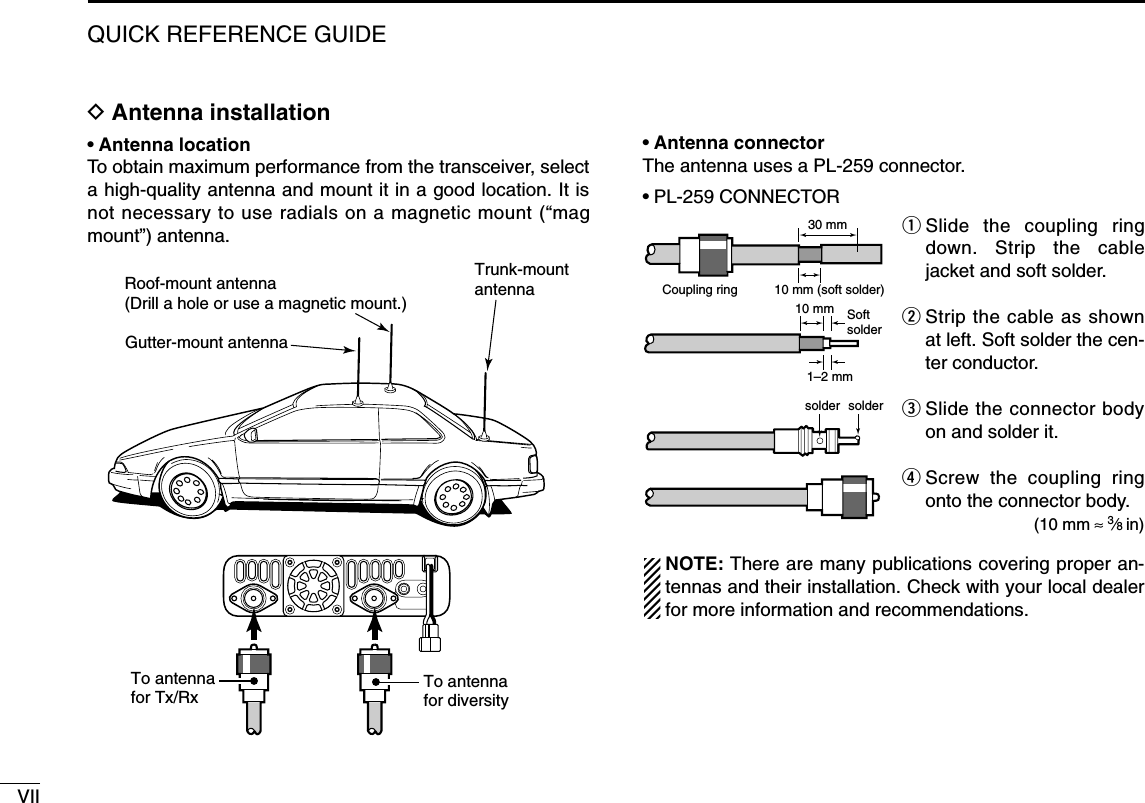
![iiiTABLE OF CONTENTSSUPPLIED ACCESSORIESqDC power cable (3 m) ………………………………………1wController cable (10 cm†; 3.9 in†) …………………………1eSeparation cable (3.4 m†; 11.2 ft†) …………………………1rMicrophone (HM-133)* ……………………………………1tFuse (20 A) …………………………………………………1yMicrophone hanger …………………………………………1uMounting screws, nuts and washers …………………1 setiMobile mounting bracket …………………………………1oMicrophone connector plate with screw ……………1 set!0Remote controller bracket …………………………………1*HM-154 HAND MICROPHONEmay be supplied with some versions.†Approx.qwetriu!0oyFOREWORD ........................................................................................... iIMPORTANT ............................................................................................ iEXPLICIT DEFINITIONS ......................................................................... iPRECAUTIONS ...................................................................................... iiSUPPLIED ACCESSORIES .................................................................. iiiTABLE OF CONTENTS ......................................................................... iiiQUICK REFERENCE GUIDE ........................................................... I–XII■Installation ....................................................................................... I■Your first contact ......................................................................... VIII■Repeater operation ........................................................................ X■Programming memory channels.................................................... XI1 PANEL DESCRIPTION ............................................................... 1–10■Front panel— controller ................................................................. 1■Function display ............................................................................. 3■Main unit ........................................................................................ 5■Microphone (HM-133) .................................................................... 7■Microphone keypad ........................................................................ 8■Optional microphones (HM-118N/TN/TAN)................................... 102 SETTING A FREQUENCY ........................................................ 11–15■Preparation ................................................................................... 11■Using the tuning dial .................................................................... 13■Using the [Y]/[Z] keys ................................................................. 13■Using the keypad ......................................................................... 13■Tuning step selection ................................................................... 14■Lock functions .............................................................................. 153 BASIC OPERATION ................................................................. 16–21■Receiving ..................................................................................... 16■Monitor function ........................................................................... 16■Squelch attenuator ....................................................................... 17■V/V, U/U simultaneous receive (Para-watch) ............................... 18■Sub band mute/sub band busy beep ........................................... 19■Transmitting ................................................................................. 20](https://usermanual.wiki/ICOM-orporated/297000/User-Guide-746386-Page-4.png)
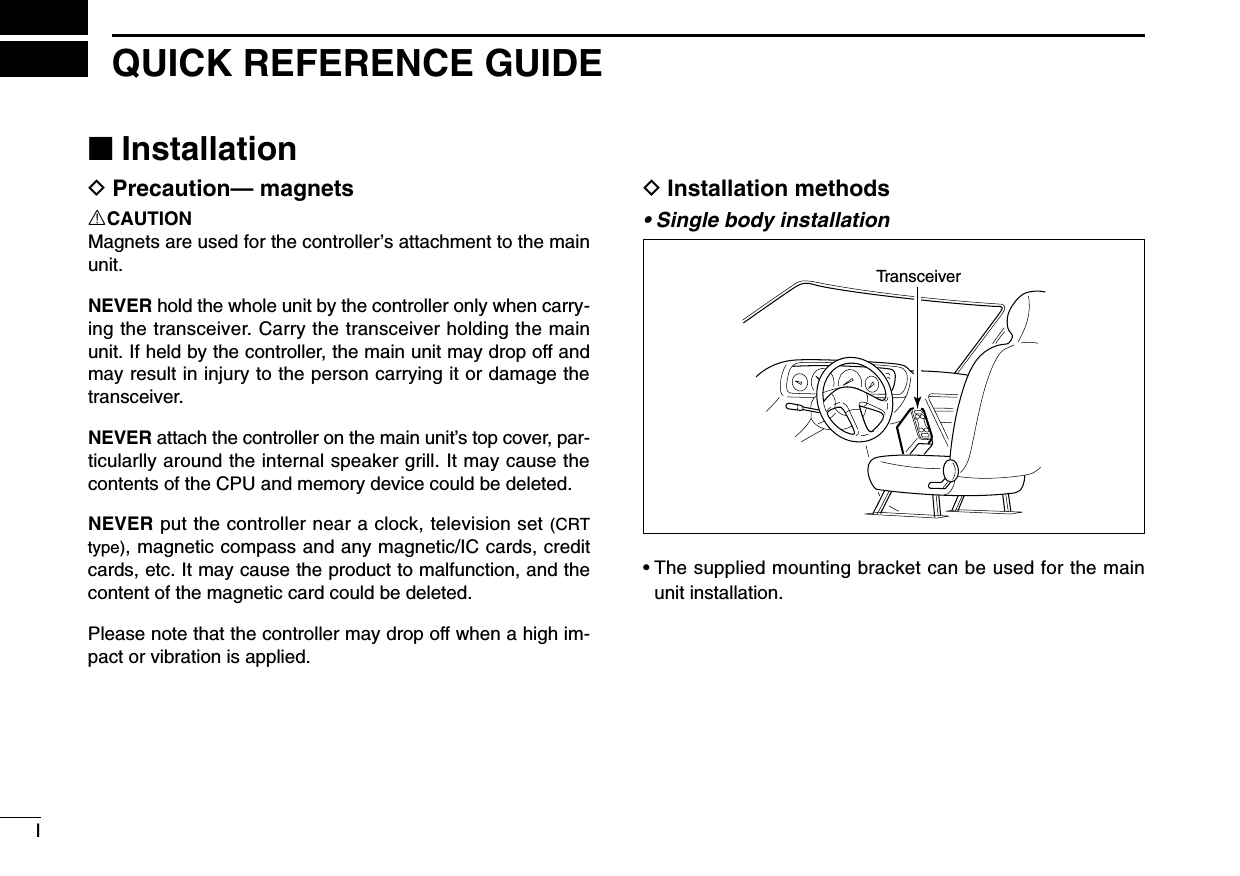
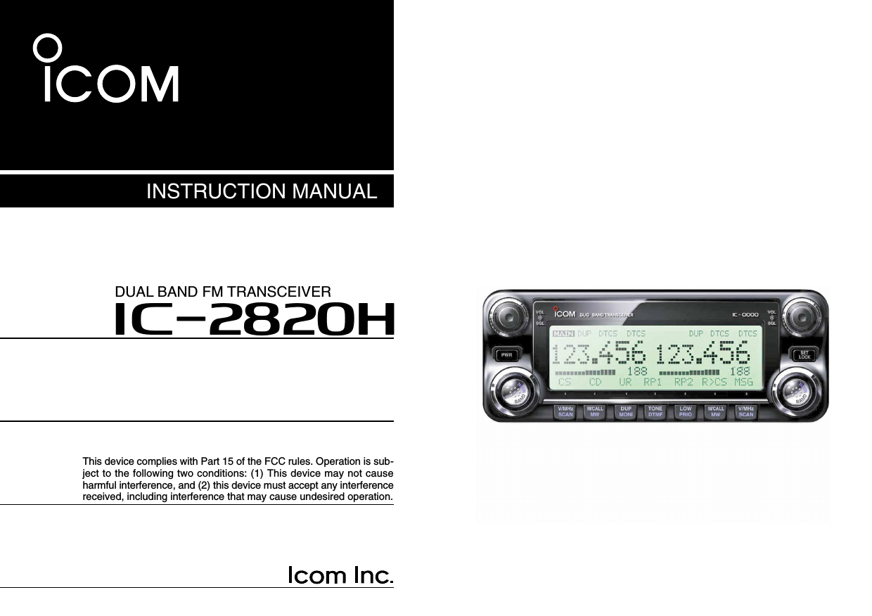
![VIIIQUICK REFERENCE GUIDE■Your first contactNow that you have your IC-2820H installed in your car orshack, you are probably excited to get on the air. We wouldlike to take you through a few basic operation steps to makeyour first “On The Air” an enjoyable experience. 1. Turning ON the transceiverBefore powering up your IC-2820H, you may want to makesure the audio volume and squelch level controls are set in9–10 o’clock positions.Although you have purchased a brand new transceiver, somesettings may be changed from the factory defaults becauseof the QC process. Resetting the CPU is necessary to startfrom factory default.➥While pushing both band’s [M/CALL•MW], push and hold[PWR] for 1 sec. to reset the CPU.2. Selecting the main bandThe IC-2820H displays 2 frequencies on left and right bandssimultaneously. However, transmission, some keys and mi-crophone’s operation are accepted for the main band only.➥Push the desired band’s (left or right) [MAIN•BAND] to se-lect the main band.•“Q” appears for the main band.Using the HM-133You can select the main band from the HM-133.PushPush again[MAIN•BAND][M/CALL•MW]While pushing both [M/CALL•MW], turn power ON.[M/CALL•MW][PWR]Set both [VOL] and [SQL] controls to 9–10 o’clock positions.Quick reference guide](https://usermanual.wiki/ICOM-orporated/297000/User-Guide-746386-Page-13.png)
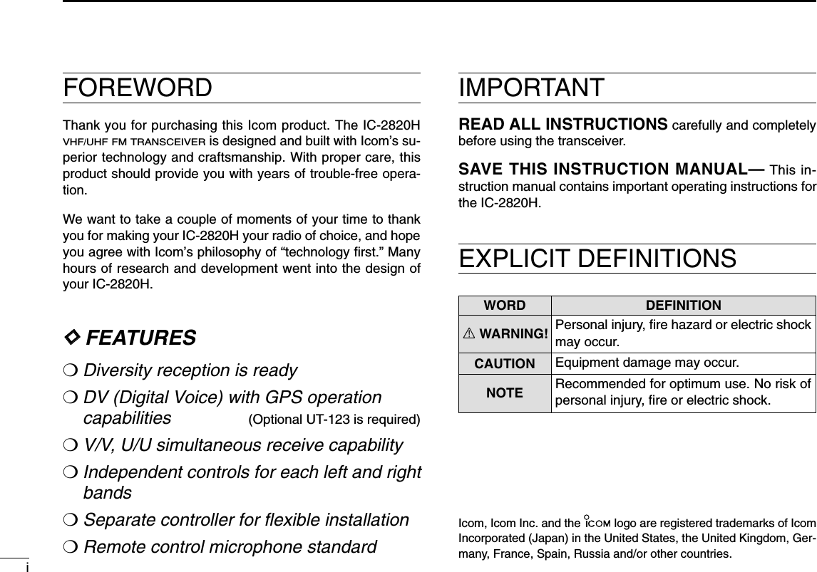
![IXQUICK REFERENCE GUIDE3. Selecting the operating frequency bandThe IC-2820H has 2 m and 70 cm bands for each left andright band. The operating band can be exchanged betweenthem, and the same bands, V/V and U/U settings are alsopossible.➥Push and hold the desired band’s (left or right)[MAIN•BAND] for 1 sec. then rotate the appropriate band’s[DIAL].•Push the [MAIN•BAND] momentarily to return to frequency in-dication.4. Tune the frequencyThe tuning dial will allow you to dial in the frequency you wantto operate. Pages ?? and ?? will instruct you on how to setthe tuning speed.Using the HM-133You can directly enter the frequency with the HM-133 keypadfor the main band. [EXAMPLE]: Setting frequency to 145.3625 MHz.PushPushPushPushRotate the desired [DIAL].[DIAL][MAIN•BAND]Frequency band initial is displayed.](https://usermanual.wiki/ICOM-orporated/297000/User-Guide-746386-Page-14.png)
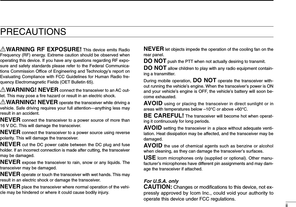
![XQUICK REFERENCE GUIDE■Repeater operation1. Setting duplex Push desired band’s [MAIN•BAND] to select the main band.Push [DUP•MONI] once or twice to select minus duplex orplus duplex.•The USA version has an auto repeater function, therefore, settingduplex is not required.2. Repeater tone Push [TONE•DTMF] several times until “TONE” appears, ifthe repeater requires a subaudible tone to be accessed.Using the HM-133Plus or minus duplex selection and the repeater tone settingcan be made easily via HM-133.Push [DUP–7(TONE)] for minus duplex; [DUP+8(TSQLS)]for plus duplex selection, push [FUNC] then [DUP–7(TONE)]to turn the repeater tone ON.PushPush , then PushPush [TONE•DTMF].Push [DUP•MONI].Quick reference guide](https://usermanual.wiki/ICOM-orporated/297000/User-Guide-746386-Page-15.png)
![XIQUICK REFERENCE GUIDE■Programming memory channelsThe IC-2820H has a total of 522 memory channels (including20 scan edges and 2 call channels) for storing often used operat-ing frequency, repeater settings, etc. Any memory channel can be recalled from either left or rightband.1. Setting a frequencyIn VFO mode, set the desired operating frequency with re-peater, tone and tuning steps, etc. ➥Push the desired band’s [V/MHz•SCAN] to select VFO.➥Rotate the same band’s [DIAL] to set the desired fre-quency.•Set other data, such as repeater tone, duplex information, tuningstep), if desired.2. Selecting a memory channel Push and hold the same band’s [M/CALL•MW] for 1 sec.,then rotate the same band’s [DIAL] to select the desiredmemory channel.•“X” indicator and memory channel number blink.3. Writing a memory channelPush and hold the same band’s [M/CALL•MW] for 1 sec. toprogram.•3 beeps sound•Return to VFO mode automatically after the program.•Memory channel number automatically increases when continuingto push the [M/CALL•MW] after programming.Push [M/CALL•MW] for 1 sec.](https://usermanual.wiki/ICOM-orporated/297000/User-Guide-746386-Page-16.png)
![XIIQUICK REFERENCE GUIDEUsing the HM-133qPush [MR/CALL] to select memory mode.wPush [ENTC(T-OFF)] first, then enter the desired memorychannel via the keypad.ePush [VFO/LOCK] to select VFO mode, then set the de-sired operating frequency, including offset direction, tonesettings, etc.➥Push [VFO/LOCK] to select VFO.➥Push [ENTC(T-OFF)] first, then enter the desired oper-ating frequency via the keypad.•Set other data, such as repeater tone, duplex information, tun-ing step, if necessary.rPush [FUNC] then push and hold [CLRA(MW)] for 1 sec.to program.•3 beeps sound•Memory channel number automatically increases when continu-ing to push [CLRA(MW)] after programming.Push , then Quick reference guide](https://usermanual.wiki/ICOM-orporated/297000/User-Guide-746386-Page-17.png)
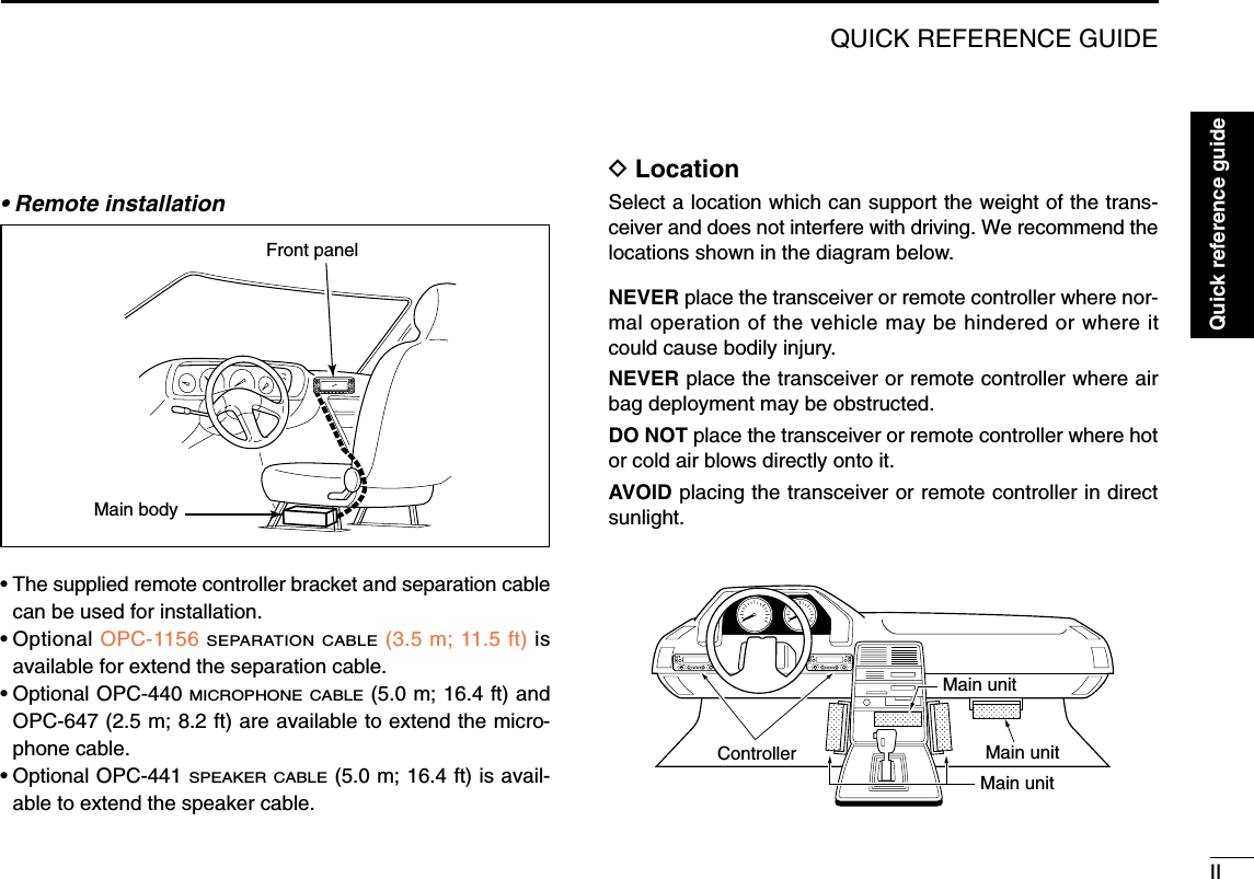
![■Front panel— controllerqPOWER KEY [PWR]Push and hold for 1 sec. to turn power ON and OFF.wFUNCTION•LOCK KEY [FF•]➥Push to display the function guide. (p. ??)➥Push and hold for 1 sec. to turn the lock function ONand OFF. (p. ??)eOUTPUT POWER•PRIORITY KEY [LOW•PRIO]➥Each push changes the output power selection. (p. ??)➥Push and hold for 1 sec. to start a priority watch. (p. ??)rTONE•DTMF KEY [TONE•DTMF]➥Each push selects a tone function. (pgs. ??, ??)•TONE, TSQL , TSQL, TSQL-R, DTCS , DTCS, DTCS-R,DSQL , DSQL, CSQL , CSQL or tone function OFF canbe selected.➥Push and hold for 1 sec. to enter DTMF set mode.(p. ??)tDUPLEX•MONITOR KEY [DUP•MONI]➥Push to select DUP–, DUP+ and simplex (no indications)operation. (p. ??)➥Push and hold for 1 sec. to turn the monitor function ONand OFF. (p. ??)DUPMONITONEDTMFLOWPRIOM/CALLMWV/MHzSCANV/MHzSCANM/CALLMWBANDMAINBANDMAINDUAL BAND TRANSCEIVER i2820HFunction display (pgs. 3, 4)qertw1PANEL DESCRIPTION1*The keys wto tare forthe MAIN band only.](https://usermanual.wiki/ICOM-orporated/297000/User-Guide-746386-Page-18.png)
![21PANEL DESCRIPTION12345678910111213141516171819ySQUELCH CONTROL [SQL]Varies the squelch level for left and right band. (p. ??)•The RF attenuator activates and increases the attenuation whenrotated clockwise to the center position and further. (p. ??)uVOLUME CONTROL [VOL] (p. ??)Adjusts the audio level for left or right band.iTUNING DIAL [DIAL]Selects the operating frequency (p. ??), memory channel(p. ??), the setting of the set mode item and the scanningdirection (p. ??) for left or right band.oMAIN•BAND KEY [MAIN•BAND]➥Push to select the main band. (p. ??)➥Push and hold for 1 sec. to enter band selectiion mode.(p. ??)!0VFO/MHz TUNING•SCAN KEY [V/MHz•SCAN]➥Push to select from VFO mode and 1 MHz (or 10 MHzfor some versions) tuning. (p. ??)➥Push and hold for 1 sec. to enter scan type selectionmode. (p. ??)•Cancels a scan when pushed during scan.!1MEMORY/CALL•MEMORY WRITE KEY [M/CALL•MW]➥Push to select and toggle memory, call and weatherchannel* modes. (pgs. ??, ??, ??, ??)*Weather channels available for USA versions only.➥Push and hold for 1 sec. to enter select memory writemode for memory channel programming. (pgs. ??, ??,??)DUPMONITONEDTMFLOWPRIOM/CALLMWV/MHzSCANV/MHzSCANM/CALLMWBANDMAINBANDMAINDUAL BAND TRANSCEIVER i2820HLeft band Right bandyuiyuioo!0 !0!1 !1*The same controls for both the left andright bands are arranged in symmetry.](https://usermanual.wiki/ICOM-orporated/297000/User-Guide-746386-Page-19.png)
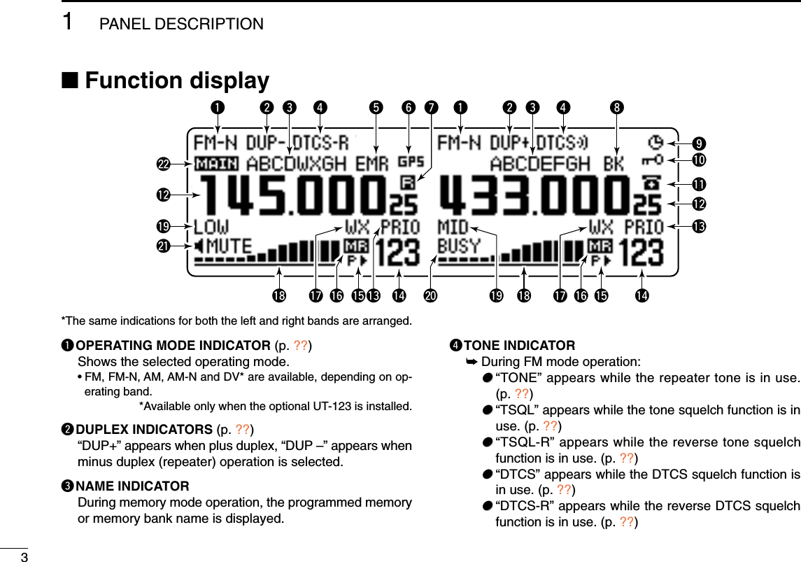
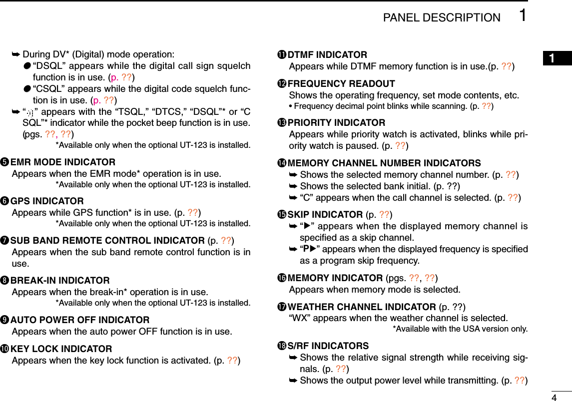
 (p. ??)Push to select an operating mode from FM, FM-N, AM,AM-N and DV* in main band.*Available only when the optional UT-123 is installed.wTUNING STEP KEY [TS](M/CALL•MW) (p. ??)Push to display the tuning step selection mode.•5.0,* 6.25,* 10, 12.5, 15,* 20, 25, 30 and 50 kHz steps are avail-able. *Not selectable in 900 MHz band.eBAND SCOPE KEY [SCP](DUP•MONI) (p. ??)➥Push to display the simple band scope and sweeps 1time.➥Push and hold for 1 sec. to display the simple bandscope and sweeps continuously.•Push [SCP](DUP•MONI) momentarily to cancel the sweep.rSCAN SKIP KEY [SKIP](TONE•DTMF) (p. ??)During in memory mode, push to select the scan skip con-dition for the selected memory channel.•“≈” appears when memory skip, “P≈” appears when programskip selection. tMEMORY NAME INDICATION KEY [M.N](LOW•PRIO)(p. ??)Push select the memory name indication condition.•Memory name, frequency and OFF selections are available.ySINGLE WATCH KEY [SNGL](M/CALL•MW) (p. ??)Push select the single watch mode.•Push [DUAL](M/CALL•MW)(for right band) to select the dualwatch mode.uMENU MODE KEY [MENU](V/MHz•SCAN) (p. ??)Push select the menu mode indication.DFunction guide 2The function guide 2 indications appear only when the op-tional UT-123 is installed and DV mode is selected.iCALL SIGN SELECT KEY [CS](V/MHz•SCAN) (p. ??)Push to display the call sign selection screen.oRECEIVED CALL SIGN RECORD KEY[CD](M/CALL•MW) (p. ??)Push to display the received call sign record screen.!0CQ KEY [CQ](DUP•MONI) (p. ??)Push to set “CQCQCQ” as the station call sign for the call.io!0!1!2!3uqwertyu](https://usermanual.wiki/ICOM-orporated/297000/User-Guide-746386-Page-24.png)
 (p. ??)Push to copy and set the previously received station callsign as the station call sign for the call.!2DV MESSAGE KEY [MSG](LOW•PRIO) (p. ??)Push to display the DV message screen.!3VOICE MEMORY KEY [REC](V/MHz•SCAN) (p. ??)Push to display the DV voice memory record screen.DFunction guide 3*The function guide 3 indications appear only when the op-tional UT-123 is installed.!4DATA KEY [DATA](V/MHz•SCAN) (p. ??)Push to toggle the GPS data communication ON and OFF.•“G•D” appears when the GPS data communication is set to ON.!5POSITION INFORMATION KEY [POSI](M/CALL•MW)(p. ??)Push to display the position information screen.!6GPS DATA STORE KEY [G-WR](DUP•MONI) (p. ??)Push and hold for 1 sec. to store the received position in-formation.!7GPS MEMORY RECALL KEY [GMR](TONE•DTMF)(p. ??)Push to select the GPS memory screen to display thestored positon information.!8DV MESSAGE KEY [MSG](LOW•PRIO) (p. ??)Push to display the DV message screen.!4 !5 !6 !7 !8 u](https://usermanual.wiki/ICOM-orporated/297000/User-Guide-746386-Page-25.png)
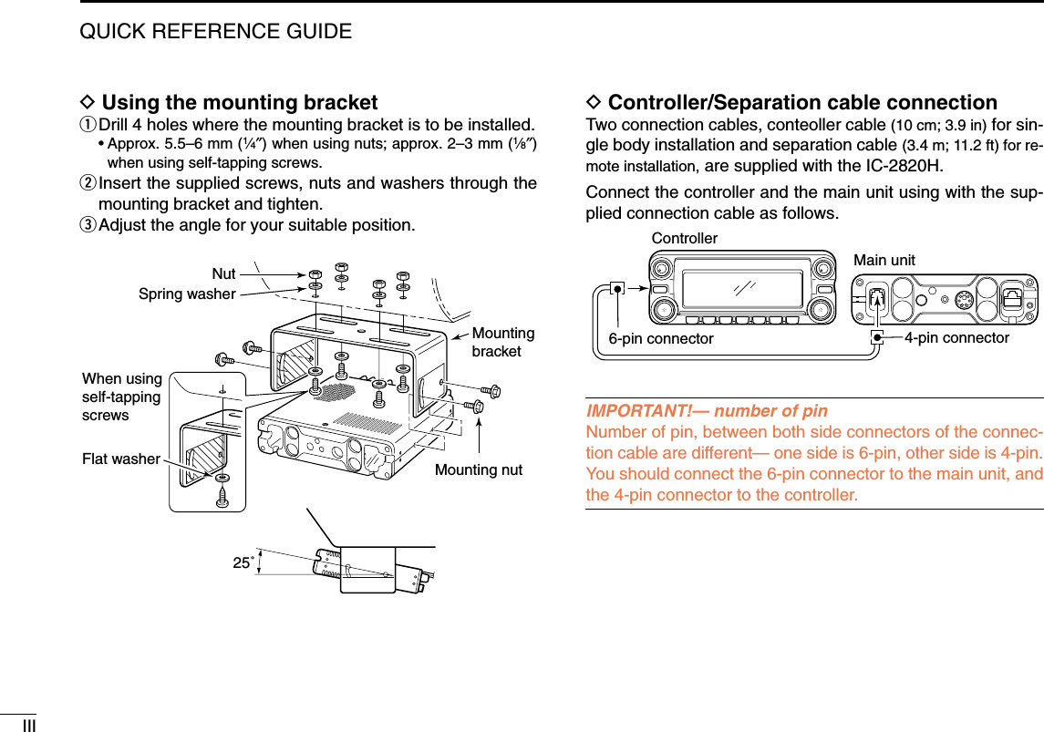
![91PANEL DESCRIPTION■Main unitqCONTROLLER CONNECTOR [CONTROLLER] (p. V)Connects the controller unit with the supplied cable.wDATA JACK [DATA]Connect to a PC via optional data communication cableOPC-1529 for slow-speed data communication in DV* modeoperation.*Available only when the optional UT-123 is installed.eGPS ANTENNA SOCKET [GPS ANT] (p. V)Connects the GPS antenna supplied with the optional UT-123.rPACKET JACKS [PACKET] (p. V)Connect a TNC (Terminal Node Controller), etc. for data com-munications. The receiver can support 9600 bps packetcommunication (AFSK).tMICROPHONE CONNECTOR [MIC]Connects the supplied or an optional microphone. q+8 V DC output (Max. 10 mA)wChannel up/downe8 V control INrPTTtGND (microphone ground)yMIC (microphone input)uGNDiData INyANTENNA CONNECTOR [ANT1]Connects a 50 Ωantenna with a PL-259 connector and a50 Ωcoaxial cable for transmission and reception.ANTENNA INFORMATIONFor radio communications, the antenna is of critical impor-tance, to maximize your output power and receiver sensi-tivity. The transceiver accepts a 50 Ωantenna and lessthan 1:1.5 of Voltage Standing Wave Ratio (VSWR). HighSWR values not only may damage the transceiver but alsolead to TVI or BCI problems.qiqwr te!1uio!0y](https://usermanual.wiki/ICOM-orporated/297000/User-Guide-746386-Page-26.png)
![101PANEL DESCRIPTION12345678910111213141516171819uCOOLING FAN Rotates while transmitting. Also rotates while receiving depending on the setting inset mode. (p. ??)iANTENNA CONNECTOR [ANT2]Connects a 50 Ωantenna with a PL-259 connector and a50 Ωcoaxial cable for diversity reception.oEXTERNAL SPEAKER JACK 1 [SP-1]Connects an 8 Ωspeaker. Outputs both left and rightbands audio when no external speaker is connected to[SP-2]. See the table below for details.•Audio output power is more than 2.4 W.!0EXTERNAL SPEAKER JACK 2 [SP-2]Connects an 8 Ωspeaker. Outputs right band’s audio only. •Audio output power is more than 2.4 W.!1POWER RECEPTACLE [DC13.8V]Accepts 13.8 V DC ±15% with the supplied DC powercable.☞NOTE: DO NOT use a cigarette lighter socket as apower source when operating in a vehicle. The plugmay cause voltage drops and ignition noise may be su-perimposed onto transmit or receive audio.• Speaker informationConnected Left band audio Right band audiospeakerNo external Internal speaker (mixed audio)speakers[SP-1] only External speaker (mixed audio)[SP-2] only Internal speaker External speaker2 external External speaker via External speaker viaspeakers [SP-1] [SP-2]](https://usermanual.wiki/ICOM-orporated/297000/User-Guide-746386-Page-27.png)
![111PANEL DESCRIPTION■Microphone (HM-133*)qVFO/LOCK KEY [VFO/LOCK]➥Push to select VFO mode. (p. 12)➥Push and hold for 1 sec. to turn the lock function ONand OFF. (p. 15)wPTT SWITCH➥Push and hold to transmit; release to receive.➥Switches between transmitting and receiving while theone-touch PTT function is in use. (p. 21)eUP/DOWN KEYS [Y]/[Z]➥Push either key to change operating frequency, mem-ory channel, set mode setting, etc. (pgs. 13, 29, 56)➥Push and hold either key for 1 sec. to start scanning.(p. 41)rACTIVITY INDICATOR➥Lights red while any key, except [FUNC] and [DTMF-S],is pushed, or while transmitting.➥Lights green while the one-touch PTT function is in use.tKEYPAD (pgs. 8, 9)yFUNCTION INDICATOR➥Lights orange while [FUNC] is activated—indicates thesecondary function of keys can be accessed.➥Lights green when [DTMF-S] is activated—DTMF sig-nals can be transmitted with the keypad.u2nd FUNCTION KEY [FUNC] iDTMF SELECT KEY [DTMF-S] (p. 50)oFUNCTION KEYS [F-1]/[F-2] (p. 66)Program and recall your desired transceiver conditions.!0BAND KEY [BAND] (p. 11)Push to select main band between left and right bands. !1MEMORY/CALL KEY [MR/CALL]➥Push to select memory mode. (p. 12)➥Push and hold for 1 sec. to select call channel. (p. 38)✔Important!All keys on the microphone function for the main band only. Mic elementqertwyuio!0!1](https://usermanual.wiki/ICOM-orporated/297000/User-Guide-746386-Page-28.png)
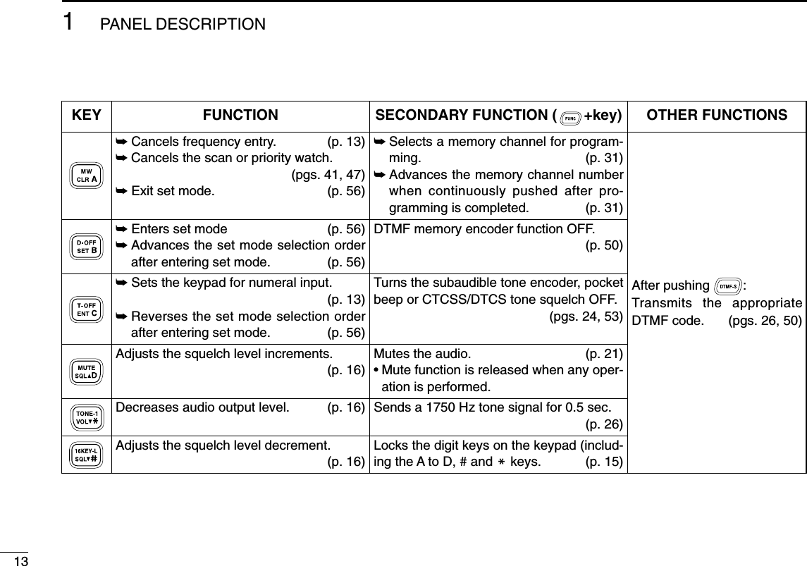
![■Microphone keypad121PANEL DESCRIPTION12345678910111213141516171819KEY FUNCTION SECONDARY FUNCTION ( +key) OTHER FUNCTIONSSwitches between opening and closing thesquelch. (p. 16)Starts and stops scanning. (p. 41)Starts and stops priority watch. (p. 47)Selects high output power. (p. 20)Selects mid. output power. (p. 20)Selects low output power (p. 20)Selects minus duplex operation. (p. 24)Selects plus duplex operation. (p. 24)Selects simplex operation. (p. 24)Increases audio output level. (p. 16)In VFO mode enters operating band select-ing condition. (p. 12)In memory mode enters bank selectingcondition. (p. 35)Starts and stops tone scanning. (p. 55)Turns the one-touch PTT function ON andOFF. (p. 21)Turns the DTCS squelch ON. (p. 53)Turns the DTCS pocket beep function ON.(p. 53)Turns the DTMF memory encoder functionON. (p. 49)Turns the subaudible tone encoder ON.(p. 24)Turns the CTCSS pocket beep functionON. (p. 53)Turns the tone squelch function ON.(p. 53)Sends a 1750 Hz tone signal while pushingand holding. (p. 26)After pushing :Transmits the appropriateDTMF code. (pgs. 26, 50)When the DTMF memory en-coder is activated, push [0] to[9] to transmit the appropriateDTMF memory contents .(p. 50)](https://usermanual.wiki/ICOM-orporated/297000/User-Guide-746386-Page-29.png)
![■Optional Microphone (HM-154)qPTT SWITCHPush and hold to transmit; release to receive.wUP/DOWN KEYS [UP]/[DN]➥Push either key to change operating frequency, mem-ory channel, set mode setting, etc. (pgs. 13, 29, 56)➥Push and hold either key for 1 sec. to start scanning.(p. 41)eUP/DN LOCK SWITCHSlide to toggle [UP]/[DN] keys function ON and OFF.wqONOFFe141PANEL DESCRIPTION12345678910111213141516171819*A different microphonemay be supplied de-pending on version.](https://usermanual.wiki/ICOM-orporated/297000/User-Guide-746386-Page-31.png)
![15SETTING A FREQUENCY2■PreparationDTurning power ON/OFF➥Push and hold [PWR] for 1 sec. to turn power ON andOFF.DMAIN bandThe IC-2820H can receive 144 MHz and 430(440) MHz bandsignals simultaneously. To activate all functions access or tochange frequency via the microphone, you must designateone band as the main band. The transceiver transmits a sig-nal on the main band only.➥Push the desired band’s [MAIN•BAND] to select the mainband.•“Q” indicates the main band.➥Push [BAND] to toggle the main band betweenleft and right bands.DOperating frequency band selectionIn the default condition, or after resetting the CPU, 2 m bandis assigned in the left band, 70 cm band is assigned in theright band. However, the 2 m band can also be assigned intothe right, and 70 cm band can also be assigned into the leftband.qPush and hold the desired band’s [MAIN•BAND] for 1 sec.•Frequency band initial appears.wRotate the same band’s [DIAL] to select the desired fre-quency band.•Pushing [Y]/[Z] on the microphone also selects the band.ePush the [MAIN•BAND] to return to frequency indication inthe selected frequency band.[DIAL][MAIN•BAND]Frequency band initial is displayed.BAND[MAIN•BAND][PWR]Note that in this manual, sections beginning with a micro-phone icon (as at left), designate operation via the HM-133microphone.](https://usermanual.wiki/ICOM-orporated/297000/User-Guide-746386-Page-32.png)
![162SETTING A FREQUENCY12345678910111213141516171819zPush [BAND] to select main band.xPush and hold [BAND] for 1 sec. to enter fre-quency band selecting condition.•The frequency band is displayed.cPush [Y]/[Z] to select the desired frequencyband.vPush [CLRA(MW)] to exit the condition, and re-turn to frequency indication.✔About extra frequency bands— USA and General versions onlyIn addition to the 2 m and 70 cm ham bands, the IC-2820HUSA and General versions have extra frequency bands foreach left and right bands as follow.See the specifications for the available frequency bands fordetails.*The frequency band initials are default indication only. Once the op-erating frequency is set in the band, the initial indication will bechanged. ✔: Available, —: Not availableDVFO and memory modesThe transceiver has 2 basic operating modes: VFO mode andmemory mode. Select VFO mode first to set an operating fre-quency.➥Push the desired band’s [V/MHz•SCAN] to select VFOmode.•When VFO mode is already selected, the digit below 10 MHz(the digit below 1 MHz or 100 kHz disappear depending on ver-sions) disappear. In this case, push [V/MHz•SCAN] again (ortwice or 3 times depending on version).➥Push [M/CALL•MW] to select memory mode.•“X” indicator appears when memory mode is selected.➥Push [VFO/LOCK] to select VFO mode.➥Push [MR/CALL] to select memory mode.•The microphone controls the main band only. Push[BAND] to toggle the main band, then push[VFO/LOCK] or [MR/CALL], if necessary.VFO/LOCK[M/CALL•MW]VFO mode is selected. “X” indicator appears whenmemory mode is selected.[V/MHz•SCAN]BANK[Y]/[Z]Frequency Left band Right bandband initial*127 ✔✔136 ✔✔146 ✔✔220 ✔—375 ✔✔440 ✔✔500 ✔✔900 —✔](https://usermanual.wiki/ICOM-orporated/297000/User-Guide-746386-Page-33.png)
![172SETTING A FREQUENCY■Using the tuning dialqRotate the desired band’s [DIAL] to set the frequency.•If VFO mode is not selected, push the same band’s[V/MHz•SCAN] to select VFO mode.•The frequency changes in the selected tuning steps. (p. ??)wTo change the frequency in 1 MHz (10 MHz for some versions)steps, push [V/MHz•SCAN], then rotate [DIAL].•Pushing and holding [V/MHz•SCAN] for 1 sec. starts scan func-tion. If scan starts, push [V/MHz•SCAN] again to cancel it.■Using the [Y]/[Z] keys➥Push [Y] or [Z] to select the desired frequency.•Push [BAND] to select the desired band (left or right)as the main band in advance.•Pushing and holding [Y]/[Z] for 1 sec. activates ascan. If scan starts, push [Y]/[Z] or [CLRA(MW)] tocancel it.■Using the keypadThe frequency can be directly set via numeral keys on the mi-crophone.zPush [BAND] to select the desired band (left orright) as the main band.•Push [VFO/LOCK] to select VFO mode, if necessary.xPush [ENTC(T-OFF)] to activate the keypad fordigit input.cPush 6 keys to input a frequency.•When a digit is mistakenly input, push [ENTC(T-OFF)]to clear the input, then repeat input from the 1st digit.•Pushing [CLRA(MW)] clears input digits and retrievesthe frequency.PushPushPushPush[EXAMPLE]: Setting frequency to 145.3625 MHz.ENTCYZWhile 1 MHz tuning step is selected, the digit below 100kHz disappear.While 10 MHz tuning step is selected, the digit below 1 MHz disappear.[V/MHz•SCAN][DIAL]](https://usermanual.wiki/ICOM-orporated/297000/User-Guide-746386-Page-34.png)
![182SETTING A FREQUENCY12345678910111213141516171819■Tuning step selectionTuning steps are the minimum frequency change incrementswhen you rotate [DIAL] or push [Y]/[Z] on the microphone.Independent tuning step for the left and right, as well as eachfrequency bands can be set for individual tuning convenience.The following tuning steps are available.•5 kHz* •6.25 kHz* •10 kHz •12.5 kHz•15 kHz* •20 kHz •25 kHz •30 kHz•50 kHz*Not selectable in 900 MHz band.☞NOTE: For convenience, select a tuning step that matchesthe frequency intervals of repeaters in your area.qPush the desired band’s [MAIN•BAND] to select the mainband.•Push the same band’s [V/MHz•SCAN] to select VFO mode, ifnecessary.wPush [F•]to display the function guide.ePush [TS](M/CALL•MW) (Left band’s) to enter tuning stepset mode.rRotate the same band’s [DIAL] to select the desired tun-ing step.tPush [F•]to exit tuning step set mode.[TS](M/CALL•MW) [F• ]](https://usermanual.wiki/ICOM-orporated/297000/User-Guide-746386-Page-35.png)
![192SETTING A FREQUENCY■Lock functionsTo prevent accidental frequency changes and unnecessaryfunction access, use the lock function. The transceiver has 2different lock functions.DFrequency lockThis function locks dials and keys electronically and can beused together with the microphone lock function.➥Push and hold [F•]for 1 sec. to turn the lock functionON and OFF.•[PTT], [DUP•MONI] (monitor function only), [VOL], [SQL] and[MAIN•BAND] (main band selection only) can be used while thechannel lock function is in use. Also, TONE-1, TONE-2, DTMFtones or DTMF memory contents can be transmitted from the mi-crophone.➥Push and hold [VFO/LOCK] for 1 sec. toturn the lock function ON and OFF.DMicrophone keypad lockThis function locks the microphone keypad.➥Push [FUNC] then [SQLZD(16KEY-L)] to turnthe microphone keypad lock function ON andOFF.•[PTT], [VFO/LOCK], [MR/CALL], [BAND], [Y], [Z],[F-1], [F-2], [DTMF-S] and [FUNC] on the micro-phone can be used.•All keys on the transceiver can be used.•The keypad lock function is released when thepower is turned OFF then ON again.16KEY-LVFO/LOCK[F• ] “ ” appear while the lock function is activated.](https://usermanual.wiki/ICOM-orporated/297000/User-Guide-746386-Page-36.png)
![203BASIC OPERATION12345678910111213141516171819■ReceivingqSet the audio level for the main band.➥Push the desired band’s [MAIN•BAND].➥Push and hold [DUP•MONI] for 1 sec. to open thesquelch.➥Rotate the main band’s [VOL] to adjust the audio level.➥Push the [DUP•MONI] to close the squelch.wSet the squelch level.➥Rotate the main band’s [SQL] fully counterclockwise inadvance, then rotate the [SQL] clockwise until the noisejust disappears.•When interference due to strong signals is received, rotatethe [SQL] clockwise again for attenuator operation. (p. 17)eSet the operating frequency in the main band. (pgs. 11–13)rWhen receiving a signal on the set frequency, squelchopens and the transceiver emits audio.•“BUSY” appears and the S/RFindicator shows the relativesignal strength for the re-ceived signal.✔CONVENIENT!The main band’s audio and squelch level can alsobe adjusted with [VOLY(TONE-1)]/[VOLZ0(TONE-2)]and [SQLYD(MUTE)]/[SQLZ#(16KEY-L)], respectively.•“VOL” for audio or “SQL” for squelch appears during set.■Transmitting☞NOTE: To prevent interference, listen on the channel be-fore transmitting by pushing and holding [DUP•MONI] for1 sec., or [MONI1(BANK)] on the microphone.qSelect the main band. (p. 11)wSet the operating frequency. (pgs. 11–13)•Select output power if desired. See section at right for details.ePush and hold [PTT] to transmit.•“$” appears.•The S/RF indicator shows the output power selection.•A one-touch PTT function is available. See p. ?? for details.•“ ” appears on the sub band screen according to the se-lected frequency band.rSpeak into the microphone using your normal voice level.•DO NOT hold the microphone too close to your mouth or speaktoo loudly. This may distort the signal.tRelease [PTT] to return to receive.IMPORTANT! (for 50 W transmission):The IC-2820H is equipped with protection circuit to protectthe power amplifier circuit from high SWR (Standing WaveRatio) and temperature. When a high SWR antenna or noantenna is connected, or when the transceiver temperaturebecomes extremely high, the transceiver reduces transmitoutput power to 15 W (approx.) automatically. CAUTION: Transmitting without an antenna will damagethe transceiver.Show set level.SQLY/ZD/#VOLY/ZM/0Appears when receiving a signal.](https://usermanual.wiki/ICOM-orporated/297000/User-Guide-746386-Page-37.png)
![213BASIC OPERATION■Selecting output powerThe transceiver has 3 output power levels to suit your oper-ating requirements. Low output powers during short-distancecommunications may reduce the possibility of interference toother stations and will reduce current consumption.➥Push [LOW•PRIO] several times to select the outputpower.*approx.•The output power can be changed while transmitting.The microphone can also be used to select output power.➥Push [HIGH4(DTCS)] for high output power;[MID5(DTCSS)] for middle output power; and[LOW6(DTMF)] for low output power.•The output power can be changed via the microphoneduring receive only.■Operating mode selectionOperating modes are determined by the modulation of theradio signals. The transceiver has total 5 operating modes(FM, FM-N, AM, AM-N and DV modes). The mode selection isstored independently for each band and memory channel.Typically, AM mode is used for the air band (118–136.995 MHz).qPush [F•]to display the function guide.wPush [MODE](V/MHz•SCAN) (Left band’s) several times toselect the desired operating mode from FM, FM-N, AM,AM-N and DV.**DV mode is available only when the optional UT-123 is installed.HIGH4MID5LOW6S/RF INDICATOR POWER OUTPUTVHF/UHF Taiwan50 W/50 W 25 W15 W*/15 W* 15 W*5 W*/5 W* 5 W*High:Mid:Low:](https://usermanual.wiki/ICOM-orporated/297000/User-Guide-746386-Page-38.png)
![223BASIC OPERATION12345678910111213141516171819■Squelch attenuatorThe transceiver has an RF attenuator related to the squelchlevel setting. Approx. 10 dB attenuation is obtained at maxi-mum setting. The squelch attenuator allows you to set a minimum signallevel needed to open the squelch. The attenuator function canbe deactivated in set mode.➥Rotate [SQL] clockwise past the 12 o’clock position to ac-tivate the squelch attenuator.•Attenuation level can be adjusted up to 10 dB (approx.) between12 o’clock and fully clockwise position.NOTE: The squelch attenuator functions even when themonitor function is in use. Thus set the [SQL] controlwithin 10 to 12 o’clock position is recommended whenusing the monitor function.DSquelch attenuator settingqPush [F•]to display the function guide.wPush [MENU](V/MHz•SCAN) (Right band’s) to enter MENUscreen.eRotate the main band’s [DIAL] to select “SET MODE,”then push [MAIN•BAND] to enter set mode.rRotate [DIAL] to select “AUTO ATT” then push[MAIN•BAND].tRotate [DIAL] to turn the squelch attenuator function ONand OFF, then push [MAIN•BAND]•Select “OFF” to deactivate the squelch attenuator function.yPush [BACK](V/MHz•SCAN) (Right bnd’s) 2 times to exit setmode.[F• ][MENU]Squelch isopen.SquelchattenuatorSquelch threshold Shallow DeepNoise squelch](https://usermanual.wiki/ICOM-orporated/297000/User-Guide-746386-Page-39.png)
![233BASIC OPERATIONThe IC-2820H can simultaneously receive two signals on thesame band, such as 144 MHz band, using the para-watchfunction.qPush and hold either the left or right band’s [MAIN•BAND]for 1 sec. to select the frequency band selecting condition.wRotate the same band’s [DIAL] to select the desired fre-quency band.ePush the [MAIN•BAND] to return to frequency indication.rSet the desired frequency.tRepeat the steps qto rfor the other band (left or right).To activate the para-watch function from the HM-133, enterthe desired frequencies for each the left and right bands usingthe direct frequency input capability via the keypad; or per-form the following operation.zPush [BAND] to select the desired band (left orright) as the main band.•Push [VFO/LOCK] to select VFO mode, if necessary.xPush [ENTC(T-OFF)] to activate the keypad fordigit input.cPush 6 keys to input a frequency.•When a digit is mistakenly input, push [ENTC(T-OFF)]to clear the input, then repeat input from the 1st digit.vPush [VFO/LOCK] to change main band, thenrepeat the steps zto cfor the other band.NOTE:•Memory channels are common for the left and right band.•Transmitting during the para-watch operation is possible.However, the sub band’s reception is deactivated duringtransmit as shown in the example at left.ENTC[Example]Can be switched between VHF and UHF■V/V, U/U simultaneous receive (Para-watch)](https://usermanual.wiki/ICOM-orporated/297000/User-Guide-746386-Page-40.png)
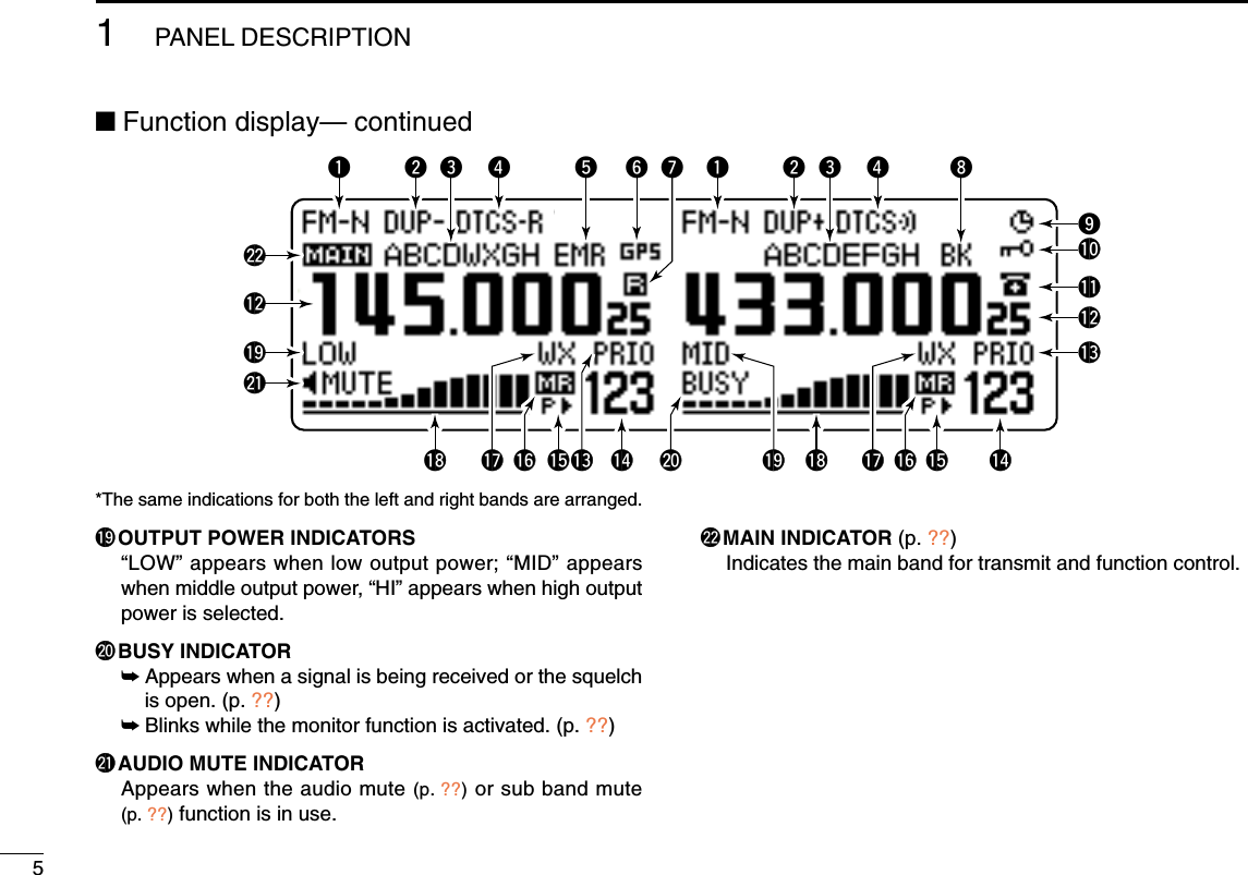
![243BASIC OPERATION12345678910111213141516171819■Sub band mute/busy beepThe sub band mute function automatically cuts out sub bandaudio signals when both main and sub band signals are re-ceived simultaneously.While operating on the main band, a beep sounds to informyou that a signal was received on the sub band. qPush [F•]to display the function guide.wPush [MENU](V/MHz•SCAN) (Right band’s) to enter MENUscreen.eRotate [DIAL] to select “SOUNDS” then push[MAIN•BAND].rRotate [DIAL] to select “SUB BAND MUTE” or “SUBBAND BEEP” then push [MAIN•BAND].tRotate [DIAL] to turn the sub band mute or sub band beepfunction ON and OFF then push [MAIN•BAND].•Select “OFF” to deactivate the squelch attenuator function.yPush [BACK](V/MHz•SCAN) (Right bnd’s) 2 times to exit setmode.■Monitor functionThis function is used to listen to weak signals without disturb-ing the squelch setting. ➥After pushing [MAIN•BAND],push and hold [DUP•MONI]for 1 sec. to open the squelch.•“BUSY” blinks.•Push [DUP•MONI] again to cancel the function.➥Push [MONI1(BANK)] to open the squelch.•Push [BAND] to select the desired band (left or right)as the main band in advance. •Push [MONI1(BANK)] again to cancel the function.NOTE: When the [SQL] adjustment is set too far clock-wise, (12–5 o’clock position) the squelch attenuator is acti-vated. To monitor weak signals on the operating frequency,deactivate the squelch attenuator function. See pg. ?? fordetails.MONI1[DUP•MONI][F• ][MENU]](https://usermanual.wiki/ICOM-orporated/297000/User-Guide-746386-Page-41.png)
![253BASIC OPERATION■Single band operationDDSingle band/Dualwatch operationDualwatch operation monitors two frequencies simultane-ously. The IC-2820H has two independent receiver circuits:left band, and right band (available frequencies, operating modeand functions are different depending on bands).Single band operation is useful when only one frequency isbeing watched. qPush [F•]to display the function guide.wPush [SNGL](M/CALL•MW) (Right band’s) to select thesignle band operation mode.•Both left and right band’s [DIAL], [MAIN•BAND], [VOL], [SQL],[V/MHz•SCAN] and [M/CALL•MW] can be used for operation.ePush [F•]to display the function guide, then push[DUAL](M/CALL•MW) (Right band’s) to return to dual watchoperation mode.DDDiversity operationThe diversity receiving compares the receiving signal strengthfrom two different antennas, ANT1 and ANT2, and automati-cally selects the strongest signal. This feature is useful whenyou are listening in a moving vehicle or the transmitting sta-tion itself is moving. Diversity receiving is available in127 MHz, 136 MHz, 146 MHz, 375 MHz, 440 MHz and500 MHz bands only.qPush [F•]to display the function guide.wPush [MENU](V/MHz•SCAN) (Right band’s) to enter MENUscreen.eRotate [DIAL] to select “SET MODE” then push[MAIN•BAND] to enter set mode.rRotate [DIAL] to select “DIVERSITY” then push[MAIN•BAND].tRotate [DIAL] to select ON, then push [MAIN•BAND].yPush [BACK](V/MHz•SCAN) (Right band’s) to exit setmode.](https://usermanual.wiki/ICOM-orporated/297000/User-Guide-746386-Page-42.png)
![263BASIC OPERATION12345678910111213141516171819When the diversity operation is in use, connect the samegrade antenna, connected to [ANT1], shuld be connectedto [ANT2].➥During single band operation with the diversity function ON,the diversity indicator appears as below.With the squelch open in FM mode while receiving a weaksignal, diversity receiving does not work properly.■One-touch PTT functionThe PTT switch can be operated as a one-touch PTT switch(each push toggles between transmit/receive). Using thisfunction you can transmit without pushing and holding thePTT switch.To prevent accidental, continuous transmissions with thisfunction, the transceiver has a time-out timer. See p. ?? fordetails.zPush [FUNC] then [PRIO3(PTT-M)] to turn theone-touch PTT function ON.•The activity indicator lights green.xPush [PTT] to transmit and push again to re-ceive.•A beep sounds when transmission is started and along beep sounds when returning to receive.cPush [FUNC] then [PRIO3(PTT-M)] to turn theone-touch PTT function OFF.•The activity indicator goes out.PTT-MWhile [ANT2] is selected;While [ANT2] is selected;Diversity indicator appears. [M/CALL•MW]](https://usermanual.wiki/ICOM-orporated/297000/User-Guide-746386-Page-43.png)
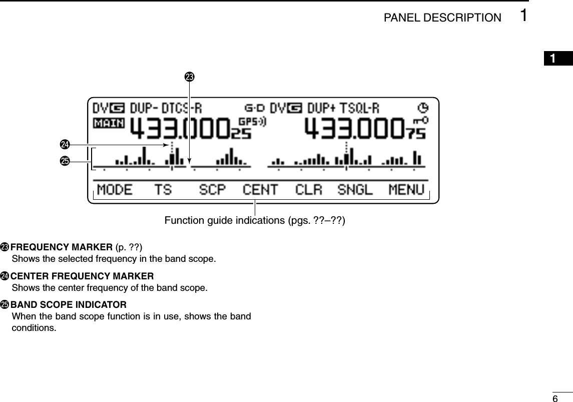
![273BASIC OPERATION■Audio mute functionThis function temporarily mutes the audio without disturbingthe volume setting. (microphone only)➥Push [FUNC] then [SQLYD(MUTE)] to muteaudio signals.•The “” indicators appear.•Push [CLRA(MW)] (or any other key) to cancel thefunction.■Band scopeThe band scope function allows you to visually check a spec-ified frequency range around the center frequency. About the sweep steps: The specified tuning step in eachfrequency band (in VFO mode) or programmed tuning step(in memory mode) is used during sweep.Sweep markerBand scope indicationSweep step indicationThe highlighted cursor indication[M/CALL•MW][DUP•MONI][F• ] [DIAL] “ ” indicators appearMUTE](https://usermanual.wiki/ICOM-orporated/297000/User-Guide-746386-Page-44.png)
![283BASIC OPERATION12345678910111213141516171819DDSingle sweepqSet the desired frequency as band scope center frequency.wPush [F•]to display the function guide.ePush [SCP](DUP•MONI) to start a single sweep.•1 short beep sounds.•Signal conditions (strengths) appear starting from the lower edgeof the range.rRotate [DIAL] to set the highlighted cursor to the desiredsignal and set the frequency of the signal.tPush [F•]to display the function guide, then push[CLR](LOW•PRIO) to clear the band scope indication.DDContinuous sweepqSet the desired frequency as band scope center frequency.wPush [F•]to display the function guide.ePush and hold [SCP](DUP•MONI) for 1 sec. to start con-tinuous sweep.•1 short and 1 long beeps sound.•Signal conditions (strengths) appear starting from the center ofthe range.rTo stop sweeping, push [F•]to display the functionguide, then push [SCP](DUP•MONI).tPush [F•]to display the function guide, then push[CLR](LOW•PRIO) to clear the band scope indication.The receive audio during sweeping can be muted insounds set mode. See page 102 for details.DDMonitoring a signalIf you find a signal that you want to monitor during/aftersweep, you can monitor the signal with the following opera-tion. qPush [F•]to display the function guide, then push[SCP](DUP•MONI) to cancel the continuousl sweep, if nec-essary.wRotate [DIAL] to tune into the desired signal.ePush [CENT](TONE•DTMF) to return to the center fre-quency.](https://usermanual.wiki/ICOM-orporated/297000/User-Guide-746386-Page-45.png)
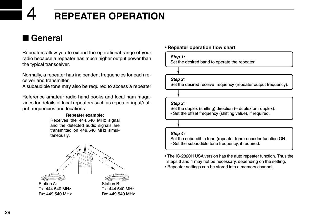
![304REPEATER OPERATION12345678910111213141516171819■Accessing a repeaterqSet the receive frequency (repeater output frequency) onthe main band. (pgs. ??–??)wPush [DUP•MONI] one or two times, to select minus du-plex or plus duplex.•“DUP–” or “DUP+” appears to indicate the transmit frequency forminus shift or plus shift, respectively.•When the auto repeater function is turned ON (available for theUSA version only), steps wand eare not necessary. (p. ??)ePush [TONE•DTMF] several times to turn ON the subaudi-ble tone encoder, according to repeater requirements.•“TONE” appears •88.5 Hz is set as the default; refer to p. ?? for tone frequency set-tings.•When the repeater requires a different tone system, see p. ??.rPush and hold [PTT] to transmit.•The displayed frequency automatically changes to the transmitfrequency (repeater input frequency).•If “OFF” appears, confirm that the offset frequency (p. ??) is setcorrectly.tRelease [PTT] to receive.yPush [DUP•MONI] to check whether the other station’stransmit signal can be received directly.uTo return to simplex operation, push [DUP•MONI] once ortwice, to clear the “DUP–” or “DUP+” indicator.iTo turn OFF the subaudible tone encoder, push[TONE•DTMF] several times until no tone indicators ap-pear.While receiving While transmitting[TONE•DTMF]“TONE” appear[DUP•MONI]“DUP–” or “DUP+” appear](https://usermanual.wiki/ICOM-orporated/297000/User-Guide-746386-Page-47.png)
![314REPEATER OPERATIONzSet the receive frequency (repeater output fre-quency) on the main band. (pgs. 11–13)xPush [DUP–7(TONE)] to select minus duplex;push [DUP+ 8(TSQLS)] to select plus duplex.cPush [FUNC] then [DUP–7(TONE)] to turn ONthe subaudible tone encoder according to re-peater requirements.•Refer to p. 25 for the tone frequency setting.•When the repeater requires a different tone system,see p. 26.vPush and hold [PTT] to transmit.bRelease [PTT] to receive.nPush [MONI1(BANK)] to check whether theother station’s transmit signal can be receiveddirectly.mPush [SIMP9(TSQL)] to return to simplex opera-tion.•“DUP” or “DUP–” indicator disappears.,To turn OFF the subaudible tone encoder, push[FUNC] then [ENTC(T-OFF)].SIMP9Push ,then .PushPushDUP–7DUP+8](https://usermanual.wiki/ICOM-orporated/297000/User-Guide-746386-Page-48.png)
![324REPEATER OPERATION12345678910111213141516171819■Subaudible tones (Encoder function)DSubaudible tonesqSelect the main band, mode/channel you wish to set thesubaudible tones to, such as VFO mode or memory/callchannel.wPush [F•]to display the function guide.ePush [MENU](V/MHz•SCAN) (Right band’s) to enter MENUscreen.rRotate [DIAL] to select “DUP/TONE…” then push[MAIN•BAND].tRotate [DIAL] to select “REPEATER TONE” then push[MAIN•BAND].yRotate [DIAL] to select and set the desired subaudible fre-quency, then push [MAIN•BAND].uPush [BACK](V/MHz•SCAN) (Right band’s) twice to exitDUP/TONE set mode.☞NOTE: The subaudible tone encoder frequency can be setin a memory/call channel temporarily. However, the set fre-quency is cleared once another memory channel or VFOmode is selected. To store the tone frequency permanently,overwrite the channel information.zSet the main band, mode/channel you wish toset the subaudible tones to, such as VFO modeor memory/call channel.•The subaudible tone frequency is independently pro-grammed into each mode or channel.xPush [SETB(D-OFF)] to enter MENU screen.cPush [Y] or [Z] to select “DUP/TONE…” thenpush [SETB(D-OFF)].vPush [Y] or [Z] to select “REPEATER TONE”then push [SETB(D-OFF)].bPush [Y] or [Z] to select the desired subaudibletone frequency then push [SETB(D-OFF)].nPush [CLRA(MW)] to return VFO mode.•Subaudible tone frequency list (unit: Hz)67.069.371.974.477.079.782.585.488.591.594.897.4100.0103.5107.2110.9114.8118.8123.0127.3131.8136.5141.3146.2151.4156.7159.8162.2165.5167.9171.3173.8177.3179.9183.5186.2189.9192.8196.6199.5203.5206.5210.7218.1225.7229.1233.6241.8250.3254.1Push SETB[V/MHz•SCAN] [F• ] [DIAL] [MAIN•BAND]](https://usermanual.wiki/ICOM-orporated/297000/User-Guide-746386-Page-49.png)
![334REPEATER OPERATIONDDTMF tones➥Push [DTMF-S], then push the keys of the de-sired DTMF digits.•The function indicator lights green.•0–9, A–D, ✱(E) and #(F) are available.•When “1” is displayed, cancel the DTMF memoryencoder in advance. (p. 50)•Push [DTMF-S] again to return the keypad to nor-mal function control.✔For your convenient!The transceiver has 16 DTMF memory channels for au-topatch operation. See p. 48 for details.D1750 Hz toneThe microphone has 1750 Hz tone capability, used for ringtone when calling, etc.zPush [FUNC].•The function indicator lights orange.xPush [✱(TONE-1)] to transmit a 1750 Hz tonecall signal for 0.5 sec.; push and hold[0(TONE-2)] to transmit a 1750 Hz tone callsignal for an arbitrary period.•The function indicator goes out automatically.Push ,then or .TONE-1TONE-2then push desired keys.Push ,DTMF-S](https://usermanual.wiki/ICOM-orporated/297000/User-Guide-746386-Page-50.png)
![344REPEATER OPERATION12345678910111213141516171819■Offset frequencyWhen communicating through a repeater, the transmit fre-quency is shifted from the receive frequency by an amountdetermined by the offset frequency. Independent offset frequencies can be set for each operatingfrequency band.qPush [MAIN•BAND] to select the desired band (left or right)as the main band.wSelect the desired mode/channel you wish to set the offsetfrequency to, such as VFO mode or memory/call channel.rPush [F•]to display the function guide then push[MENU](V/MHz•SCAN) (Right band’s) to enter MENUscreen.tRotate the [DIAL] to select “DUP/TONE…”, then push[MAIN•BAND].yRotate the [DIAL] to select “OFFSET FREQ” item, thenpush [MAIN•BAND].uRotate the main band’s [DIAL] to set the desired offset fre-quency.iPush [BACK](V/MHz•SCAN) (Right band’s) twice to exitDUP/TONE set mode.zPush [BAND] to select the desired band (left orright) as the main band.•Enter the desired frequency via the keypad if neces-sary.xSelect the desired mode/channel you wish toset the offset frequency to, such as VFO modeor memory/call channel.•The offset frequency can be independently pro-grammed into each mode or channel.cPush [SETB(D-OFF)] to enter MENU screen.vPush[Y] or [Z] to select “DUP/TONE…” thenpush [SETB(D-OFF)].vPush[Y] or [Z] to select “OFFSET FREQ” thenpush [SETB(D-OFF)].bPush [Y] or [Z] to set the desired offset.•Direct frequency entry from the keypad is not possi-ble.nPush [CLRA(MW)] to exit set mode.☞NOTE: The offset frequency can be set in amemory/call channel temporarily. However, theset frequency is cleared once another memorychannel or VFO mode is selected. To store theoffset frequency permanently, overwrite thechannel information.SETB[V/MHz•SCAN] [F• ] [DIAL] [MAIN•BAND]](https://usermanual.wiki/ICOM-orporated/297000/User-Guide-746386-Page-51.png)
![354REPEATER OPERATIONThe U.S.A. and Korean versions automatically use standardrepeater settings (duplex ON/OFF, duplex direction, tone encoderON/OFF) when the operating frequency falls within or outsideof the general repeater output frequency range. The offsetand repeater tone frequencies are not changed by the autorepeater function, reset these frequencies, if necessary.DFrequency range and offset direction•U.S.A. version•Korean versionqPush [F•]to display the function guide.wPush [MENU](V/MHz•SCAN) (Right band’s) to enter MENUscreen.eRotate [DIAL] to select “SET MODE” then push[MAIN•BAND].rRotate [DIAL] to select “AUTO REPEATER” then push[MAIN•BAND].tRotate [DIAL] to select the auto repeater setting.[U.S.A. version]:•“ON1”: Activates duplex only. (default)•“ON2”: Activates duplex and tone.•“OFF”: Auto repeater function is turned OFF.[Korean version]:•“ON”: Activates duplex and tone. (default)•“OFF”: Auto repeater function is turned OFF.yPush [BACK](V/MHz•SCAN) (Right band’s) twice to exitfrom set mode.Auto Repeater set: ON1(USA version)FREQUENCY RANGE SHIFT DIRECTION439.000–440.000 MHz “DUP–” appearsFREQUENCY RANGE SHIFT DIRECTION147.000–147.395 MHz “DUP+” appears442.000–444.995 MHz “DUP+” appears447.000–449.995 MHz “DUP–” appears145.200–145.495 MHz146.610–146.995 MHz “DUP–” appears■Auto repeater U.S.A./KOREAN versions only](https://usermanual.wiki/ICOM-orporated/297000/User-Guide-746386-Page-52.png)
![37MEMORY OPERATION5■General descriptionThe transceiver has 522 memory channels including 20 scanedge memory channels (10 pairs), and 2 call channels. Eachof these channels can be individually programmed with oper-ating frequency (pgs. ??–??), duplex direction (p. ??) and offset(p. ??), subaudible tone encoder or tone squelch and its tonefrequency (pgs. ??, ??, ??, ??) and skip information* (p. ??). In addition, a total of 26 memory banks, A to Z, are availablefor usage by group, etc.*except for scan edge memory channels.■Memory channel selectionDUsing the tuning dialqPush the desired band’s[M/CALL•MW] severaltimes to select memorymode.•“X” indicator appearwRotate the same band’s[DIAL] to select the de-sired memory channel.•Programmed memorychannels only can be se-lected.DUsing the [Y]/[Z] keyszPush [BAND] to select the desired band asthe main band.xPush [MR/CALL] to select memory mode.cPush [Y] or [Z] to select and set the desiredmemory channel.•Pushing and holding [Y]/[Z] for 1 sec. activatesa scan.•If scan is activated, push [Y]/[Z] again or push[CLRA(MW)] to stop it.DUsing the keypadzPush [BAND] to select the desired band asthe main band.xPush [MR/CALL] to select memory mode.cPush [ENTC(T-OFF)] to activate the keypadfor numeral input.vPush 3 appropriate digit keys to input a chan-nel number. •Blank channel can be selected.•Push only 1 appropriate digit key, [VOLY0(TONE-2)] to [SIMP9(16-KEY-L)]] then push [MM(TONE-1)]or [SQLZ#(16KEY-L)] to select scan edge chan-nels. “MM” and “#” can be used for “A” and “b” re-spectively.MR/CALLY/ZMR/CALLY/Z[M/CALL•MW][DIAL]åXßappears](https://usermanual.wiki/ICOM-orporated/297000/User-Guide-746386-Page-54.png)
![VFO settings, including MENU group’s contents such as sub-audible tone frequency, offset, can be programmed into amemory channel.qSet the desired frequency in the desired band (left or right). ➥Push the desired band’s [V/MHz•SCAN] to select VFOmode.➥Set the frequency using the same band’s [DIAL].➥Set other data (e.g. tone frequency, duplex information, etc.)if required.wPush and hold the same band’s [M/CALL•MW] for 1 sec.•2 beeps sound•“X” indicator and the memory channel number blink.eRotate the [DIAL] to select the memory channel to be pro-grammed.•Memory channels not yet programmed are blank.rPush and hold the same band’s [M/CALL•MW] for 1 sec.to program.•3 beeps sound•Memory channel number automatically increases when contin-uing to push [M/CALL•MW] after programming.✔CONVENIENTMemory programming can be performed in versatile wayse.g. memory channel to the same (or different) memory chan-nel, memory channel to the call channel, etc.385MEMORY OPERATION12345678910111213141516171819■Programming a memory channel[EXAMPLE]: Programming 145.870 MHz into memory channel 20 (blank channel) via the controller.Push Rotate for setting frequency, etc. Push and hold for 1 sec.Rotate Push and hold for 1 sec. and continue to push ➠Beep“V/MHzSCANM/CALLMWM/CALLMWBANDMAINBANDMAINBeepBeepBeep“““““BeepBeep“““““](https://usermanual.wiki/ICOM-orporated/297000/User-Guide-746386-Page-55.png)
![DProgramming a memory channel via the microphoneThe microphone can also be used to program mem-ory channels.zSet the desired frequency in VFO mode.➥Push [VFO/LOCK] to select VFO mode.➥Set the frequency using the keypad.➥Set other data (e.g. offset frequency, duplex direction, sub-audible tone encoder ON/OFF and its frequency), if neces-sary.xPush [MR/CALL] to enter memory mode.cPush [ENTC(T-OFF)], then set the desired memory chan-nel using the keypad.vPush [VFO/LOCK] to select VFO mode.bPush [FUNC] then push and hold [CLRA(MW)] for 1 sec. toprogram.➥3 beeps may sound and the VFO contents (including thesubaudible tone frequency, etc.) are programmed.➥Memory channel number increases when continuing topush [CLRA(MW)] after programming.MW395MEMORY OPERATION[EXAMPLE]: Programming 145.870 MHz into memory channel 20 (blank channel) via the microphone.Beep“Beep“BeepBeepBeep“““““Push ,Push then for 1 sec. and continue to push ➠MR/CALLPush then Push Push](https://usermanual.wiki/ICOM-orporated/297000/User-Guide-746386-Page-56.png)
![405MEMORY OPERATION12345678910111213141516171819■Memory bank selectionThe IC-2820H has a total of 26 banks (A to Z). All memorychannels, regular, scan edges and call channels are assignedinto the desired bank for easy memory management.qPush the desired band’s [M/CALL•MW] several times toselect memory mode, if desired.wPush and hold the same band’s [MAIN•BAND] for 1 sec. • The memory channel number blinks.eRotate the same band’s [DIAL] to select the desired bank,A to Z.•Banks that have no programmed contents are skipped.rPush the [MAIN•BAND] to set the bank group.•Bank initial and bank channel stop blinking.tRotate the same band’s [DIAL] to select the bank channel.yTo return to regular memory mode, push and hold the[MAIN•BAND] for 1 sec. then rotate the [DIAL] to selectmemory channel number indication.zPush [MR/CALL] to select memory mode, if de-sired.xPush [FUNC] then [MONI1(BANK)] to selectmemory bank condition.Or, push and hold [BAND] for 1 sec. to selectmemory bank condition.•Memory channel blinkscPush [Y]/[Z] to select the desired bank, A to Z.•Only programmed memory bank can be selected.vPush [CLRA(MW)] to set the bank.Or, push [BAND] to set the bank.•Bank initial and bank channel stops blinking.bPush [Y]/[Z] to select the desired contents inthe bank.•No channel numbers are displayed for memory bankoperation.nTo return to regular memory condition, push[FUNC], [MONI1(BANK)] then push [Y]/[Z] toselect memory channel number indication.Or, push and hold [BAND] for 1 sec., then push[Y]/[Z] to select memory channel number indi-cation.BANK[Y]/[Z]Bank initial and bankchannel blinkEnter the memory bank condition mode.[MAIN•BAND]](https://usermanual.wiki/ICOM-orporated/297000/User-Guide-746386-Page-57.png)
![415MEMORY OPERATION■Memory bank settingqPush the desired band’s [M/CALL•MW] several times toselect memory mode, then rotate the same band’s [DIAL]to select the desired memory channel.wPush and hold the same band’s [M/CALL•MW] for 1 sec. •“X” and memory number indication blinks.ePush [SEL](V/MHz•SCAN) (Left band’s) several times to se-lect “BANK” setting stand-by condition.•“X” indicator blinks.rPush [EDIT](M/CALL•MW) (Right band’s) to edit.•“X” and 1st digit blink.tRotate the same band’s [DIAL] to select the desired bankgroup.•A to Z bank groups available.yPush [>](M/CALL•MW) (Left band’s) then rotate [DIAL] toselect the desired bank channel.•“X” and last 2 digits blink.uPush [BACK](V/MHz•SCAN) (Right band’s) to set the bankinitial and channel number.•“X” indicator blinks.iPush and hold [S.MW](M/CALL•MW) (Left band’s) for 1 sec.to overwrite the memory channel to store the memory banksettings.oRepeat steps qto ito set another memory channel intothe same or another bank.](https://usermanual.wiki/ICOM-orporated/297000/User-Guide-746386-Page-58.png)
![425MEMORY OPERATION12345678910111213141516171819■Programming memory/bank/scan nameEach memory channel can be programmed with an alphanu-meric channel name for easy recognition and can be indi-cated independently by channel. Names can be a maximumof 8 characters— see the table right below for available char-acters.qSelect the desired memory channel to be programmed.➥Push [M/CALL•MW] several times to select memorymode, then rotate the same band’s [DIAL] to select thedesired memory channel.wPush and hold the same band’s [M/CALL•MW] for 1 sec.to enter select memory write mode.•“X” indicator and the memory channel number blink.ePush [SEL](V/MHz•SCAN) (Left band’s) several times to se-lect programming the name conditions.“BANK”: The memory bank “B NAME”: The bank name (appears only when the selectedmemory bank is edited into a bank)“M NAME”: The memory name“S NAME”: The scan name (appears only when a scan edgechannel is selected)•Frequency readouts disappear.rPush [EDIT](M/CALL•MW) (Right band’s) to edit.•“X” indicator and cursor blinks.tRotate the same band’s [DIAL] to select the desired char-acter.•The selected character blinks.•Push [Aa](TONE•DTMF) to turn the character group from al-phabetical characters capital letters or lower case letters.•Push [12](M/CALL•MW) (Right band’s) to turn the character groupfrom numbers or symbols.•Push [>](M/CALL•MW) (Left band’s) to move the cursor right;push [<](V/MHz•SCAN) (Left band’s) to move the cursor left. •Push [CLR](DUP/MONI) to clear the selected character.yRepeat steps eand tuntil the desired channel name isprogrammed.uPush [BACK](V/MHz•SCAN) (Right band’s) to set the name.yPush and hold [S.MW](M/CALL•MW) (Right band’s) for1 sec. to overwrite the memory channel to store the mem-ory name.NOTE: Only one bank name can be programmed intoeach bank. Therefore, the previously programmed bankname will be displayed when bank name indication is se-lected. Also, the programmed bank name is assigned forthe other bank channels automatically.DDAvailable charactersABCDEFGHIJKLMNOPQRSTUVWXYZabcdefghijklmnopqrstuvwxyz0123456789(Space)! ''#$%&'()*+,-./:;<=>?@[\]^_`{|}~](https://usermanual.wiki/ICOM-orporated/297000/User-Guide-746386-Page-59.png)
![435MEMORY OPERATION[EXAMPLE]: Programming the bank name “AIR” into the scan edge channel 3A.Enter “I” and “R” with (Main band's) and (Left band's), then push (Right band's) to select memory write mode. V/MHzSCANV/MHzSCANM/CALLMWM/CALLMWPush and hold (Left band's) for 1 sec. to program. M/CALLMWM/CALLMWPush (Main band's) to select memory mode.BANDMAINRotate (Main band's) to select scan edge channel 3A.BANDMAINBANDMAINRotate (Main band's) to select “A”, then push . M/CALLMWM/CALLMWPush and hold (Main band's) for 1 sec. to enter select memory write condition.Push (Main band's) several times to select “B NAME”.Push (Right band's) to enter bank name edit mode.*Select “M NAME” or “S NAME” when programing the memory name or the scan name, respectively.Bank name edit modeSelect memory write modeMemory mode SELEDITDDTo indicate the channel nameThe channel name indication can be set independently foreach memory channel.qSelect the desired memory channel in the main band.➥Push the same band’s [M/CALL•MW] several times toselect memory mode, then rotate the same band’s [DIAL]to select the desired memory channel.•“X” and memory channel number appear.wPush [F•]to display the function guide.ePush [M.N](LOW•PRIO) several times to select “MEM-ORY,” “FREQ” or OFF.•When “MEMORY” is selected, the programmed memory name isindicated above frequency indication; when “FREQ” is selecte,the programmed memory name is indicated at the frequency in-dication and the programmed frequency is indicated above thememory name.rPush [F•]twice to exit the function guide.NOTE: When no memory name is programmed, the storedfrequency is displayed.](https://usermanual.wiki/ICOM-orporated/297000/User-Guide-746386-Page-60.png)
![■Transferring memory contentsThis function transfers a memory channel’s contents to VFO(or another memory/call channel). This is useful when searchingfor signals around a memory channel frequency and for re-calling the offset frequency, subaudible tone frequency etc.DMemory/call➪VFOqSelect the desired band’s (left or right) memory or call chan-nel.➥Push the desired band’s [M/CALL•MW] several times toselect memory mode or call channel, then rotate thesame band’s [DIAL] to select the desired memory or callchannel.wPush and hold [M/CALL•MW] for 1 sec. to transfer the se-lected memory/call channel contents to the VFO.•VFO mode is selected automatically.zPush [BAND] to select the desired band asthe main band, if necessary.xSelect the memory/call channel to betransferred.➥Push [MR/CALL] to select memory mode,then select the desired memory channelvia [Y]/[Z] or keypad.➥Push and hold [MR/CALL] for 1 sec. thenpush [Y]/[Z] to select the call channel.cPush [FUNC], then push and hold[CLRA(MW)] for 1 sec. to transfer the se-lected memory/call channel contents to theVFO.•VFO mode is selected automatically.MR/CALLMW[Y]/[Z]445MEMORY OPERATION12345678910111213141516171819[EXAMPLE]: Transferring memory channel 30 contents to VFO.Push to select memory mode.Front panel operation:HM-133 operation:Push to select memory mode.Rotate for selecting memory channel.Select memory channel.Push and hold (same band’s) for 1 sec.Push then push and hold for 1 sec.M/CALLMWM/CALLMWBANDMAIN](https://usermanual.wiki/ICOM-orporated/297000/User-Guide-746386-Page-61.png)
![455MEMORY OPERATIONDMemory/call➪call/memoryqSelect the memory/call channel to be transferred.➥Push the desired band’s [M/CALL•MW] several timesto select memory mode or call channel, then rotate thesame band’s [DIAL] to select the desired memory orcall channel.wPush and hold the same band’s [M/CALL•MW] for 1 sec.•“X” indicator and the memory channel number blink, andshows VFO conditions.eRotate the same band’s [DIAL] to select the target memorychannel.•“C1” or “C2” blinks when the call channel is selected.•Scan edge channels, 1A/1b, 2A/2b, 3A/3b, 4A/4B, 5A/5b canalso be selected.rPush and hold the [S.MW](M/CALL•MW) (Left band’s) for1 sec. to transfer the selected memory/call channel con-tents to the target memory.•The targeted memory and transferred contents are indicated.[EXAMPLE]: Transferring memory channel 30 contents to channel 31.Select the target channel.Select the memory channel,then push and hold for 1sec. Push and hold for 1 sec.M/CALLMWM/CALLMWS.MW](https://usermanual.wiki/ICOM-orporated/297000/User-Guide-746386-Page-62.png)
![465MEMORY OPERATION12345678910111213141516171819■Memory clearingContents of programmed memories can be cleared (blanked),if desired.qPush [V/MHz•SCAN] to select VFO mode in the desiredband (left or right).wPush and hold the same band’s [M/CALL•MW] for 1sec.•“X” indicator and the memory channel number blink.eRotate [DIAL] to select the memory channel to be cleared. rPush and hold [CLR](DUP•MONI) for 1sec. to clear.•3 beeps sound, then the frequency is cleared.•“X” indicator and the channel number blink continuously.•When clearing the call channel, the current VFO conditions arere-programmed into the call channel automatically.tPush [BACK](V/MHz•SCAN) (Right band’s) to return to VFOmode.NOTE: Be careful!— the contents of cleared memoriesCANNOT be recalled.[EXAMPLE]: Clearing memory channel 20.Push (Main band’s) to select VFO. Rotate (Main band’s) for selectingmemory channel to be cleared.Push and hold (Main band’s) for 1 sec.Push .V/MHzSCANV/MHzSCANM/CALLMWPush and hold for 1 sec. memory clearing.DUPMONIBANDMAINBeepBeepBeep“““““CLR BACK](https://usermanual.wiki/ICOM-orporated/297000/User-Guide-746386-Page-63.png)
![475MEMORY OPERATIONContents of programmed memory banks can be cleared ortransferred to another bank.INFORMATION: Even if the memory bank contents arecleared, the memory channel contents still remain pro-grammed.qSelect the desired bank contents to be transferred orerased from the band (left or right).➥Push the desired band’s [M/CALL•MW] several timesto select memory mode.➥Push and hold the same band’s [MAIN•BAND] for1 sec. then rotate the same band’s [DIAL] to select thedesired memory bank.➥Push the [MAIN•BAND] to select the bank then rotatethe [DIAL] to select the desired bank channel.•Bank initial and bank channel stops blinking.wPush and hold the same band’s [M/CALL•MW] for 1 sec.•“X” indicator and the memory channel number blinkePush [SEL](V/MHz•SCAN) (Left band’s) several times to se-lect bank, then push [EDIT](M/CALL•MW) (Right band’s).rRotate [DIAL] to select the desired bank initial (A to Z) totransfer.•Select no indication, “– – – –,” when erasing the contents fromthe bank.tPush [>](M/CALL•MW) (Left band’s) then rotate the sameband’s [DIAL] to select a bank channel, if desired.yPush [BACK](V/MHz•SCAN) (Right band’s) to back the se-lect memory write mode.uPush and hold [S.MW](M/CALL•MW) (Left band’s) for 1 sec.to be transferred or erased.iRepeat steps qto tfor transferring or erasing an anotherbanks contents.■Erasing/transferring bank contents](https://usermanual.wiki/ICOM-orporated/297000/User-Guide-746386-Page-64.png)
![486CALL CHANNEL OPERATION12345678910111213141516171819■Call channel selectionCall channel is pre-programmed memory channel that can beaccessed by simply pushing call channel button.➥Push [M/CALL•MW] sev-eral times to select thecall channel mode thenrotate the same band’s[DIAL] to select the de-sired call channel.•“C0” or “C1” appears in-stead of memory channelnumber indication.•Push the [M/CALL•MW]several times to select mem-ory mode, or push the sameband’s [V/MHz•SCAN] to se-lect VFO mode.➥Push and hold [MR/CALL] for 1 sec. to selectthe call channel mode then push [Y]/[Z] toselect the desired call channel in the mainband.•Push [MR/CALL] to select memory mode, or push[VFO/LOCK] to select VFO mode.■Call channel transferringDCall➪VFO/MemoryqPush the desired band’s [M/CALL•MW] several times toselect cal channel mode, then rotate the same band’s[DIAL] to select the desired call channel.•“C0” or “C1” appears.wPush the [M/CALL•MW] for 1 sec., then rotate the [DIAL]to select the memory channel to transfer the contents to.•“X” indicator and memory channel number blink.•To transfer to the VFO mode, select VFO indication with the[DIAL]. ePush the [M/CALL•MW] for 1 sec. to transfer the contents.zPush [MR/CALL] for 1 sec. then push [Y]/[Z]to select the desired call channel in the mainband.xPush [FUNC], then [CLRA(MW)] for 1 sec. totransfer the contents.•To transfer to the VFO only. MR/CALLMW[Y]/[Z]MR/CALLDUO BAND TRANSCEIVER i2820“C0” or “C1” appears[DIAL][M/CALL•MW]✔INFORMATIONWhen the VFO mode is selected fromthe call channel, a small “c” appearsinstead of memory channel number.](https://usermanual.wiki/ICOM-orporated/297000/User-Guide-746386-Page-65.png)
![496CALL CHANNEL OPERATION■Programming a call channelOperating frequency, duplex information, subaudible tone in-formation (tone encoder or tone squelch ON/OFF and its fre-quency) can be programmed into the call channel.qSet the desired frequency in VFO mode.➥Push the desired band’s [V/MHz•SCAN] to select VFOmode.➥Set the frequency using the same band’s [DIAL].➥Set other data as desired.wPush the same band’s [M/CALL•MW] for 1 sec.eRotate the [DIAL] to select the desired call channel.•“X” indicator and “C0” or “C1” blink.rPush the [M/CALL•MW] for 1 sec. to program.•3 beeps sound and the unit returns to VFO mode automatically.zPush and hold [MR/CALL] for 1 sec. to selectcall channel mode.➥Push [Y] or [Z] to select desired call chan-nel.xPush [VFO/LOCK] to select VFO mode.➥Set the frequency.cPush [FUNC] then [CLRA(MW)] for 1 sec. toprogram.•3 beeps sound.MR/CALLMW[Y]/[Z][EXAMPLE]: Programming 145.120 MHz into the call channel 1 via the microphone.Push , then push for 1 sec. ➠Push to select the call channel “C1”.BeepBeepBeep“““““Set the frequency.Push and hold for 1 sec. to select call channel mode.MR/CALL Push to select VFO mode.VFO/LOCK](https://usermanual.wiki/ICOM-orporated/297000/User-Guide-746386-Page-66.png)
 in eitherVFO or memory mode.BandedgeBandedgeScanSKIP SKIPJumpPROGRAMMED SCAN(p. ??)Repeatedly scans betweentwo user-programmed fre-quencies. Used for checkingfor frequencies within a speci-fied range such as repeateroutput frequencies, etc.Bandedge xxA xxBBandedgeScan edgesScanJumpMEMORY (SKIP) SCAN(p. ??)Repeatedly scans memorychannels except those set asskip channel. Skip channelscan be turned ON and OFF infunction guide.SKIPSKIPM 0 M 4M 1 M 2 M 3M 5M 199M 6](https://usermanual.wiki/ICOM-orporated/297000/User-Guide-746386-Page-67.png)
![517SCAN OPERATION■Scan start/stopDPreparationScan resume condition (p. ??); program the scan edges(pgs. ??, ??); program 2 or more memory channels (pgs. ??,??); set skip settings, if desired (p. ??).DOperationqSelect VFO mode for full/programmed scan with[V/MHz•SCAN]; or memory mode for memory scan with[M/CALL•MW] in the desired band.•Select the desired bank with the same band’s [MAIN•BAND] forbank scan.wSet the squelch to the point where noise is just muted.ePush and hold [V/MHz•SCAN] for 1 sec. to start the scan.•To change the scanning direction, rotate the same band’s [DIAL].•The memory channel readout blinks the scan type as follows:rPush [FF•]to switch the full and programmed scan (P1to P9), if VFO is selected in step q.tTo stop the scan, push the [V/MHz•SCAN] in the desiredband.zPush [VFO/LOCK] to select VFO mode forfull/programmed scan; push [MR/CALL] to selectmemory mode for memory scan, in the mainband.•Push [FUNC] then [MONI1(BANK)] to select a bankfor bank scan.xPush [SQLYD(MUTE)] or [SQLZ#(16KEY-L)] toset the squelch to the point where noise is justmuted.cPush [SCAN2(T-SCAN)] to start the scan.•Push [Y] or [Z] for 1 sec. also starts the scan.vPush [SETB(D-OFF)] to switch the full and pro-grammed scan (P1, P2, P3, P4 and P5), if VFOis selected in step z.bTo stop the scan push [SCAN2(T-SCAN)] or[CLRA(MW)].SCAN2SETB• During full scan • During programmed scan • During memory scan • During bank scanIndicates scan edge channels.• P1 stands for 1A/1BIndicates bank initial.Rotate [DIAL] to select “ALL” (full) or programmed scan (P1 to P9) in sequence.](https://usermanual.wiki/ICOM-orporated/297000/User-Guide-746386-Page-68.png)
![527SCAN OPERATION12345678910111213141516171819■Scan edges programmingScan edges can be programmed in the same manner asmemory channels. Scan edges are programmed into scanedges, 1A/1B to 9A/9B, in memory channels.qSet the edge frequency of the desired frequency range inVFO mode:➥Set the frequency using the desired band’s [DIAL].➥Set other data (e.g. repeater settings, etc.) if desired.wPush the same band’s [M/CALL•MW] for 1 sec.•“X” indicator and channel number blink.eRotate the [DIAL] to select one of scan edge channel, 1Ato 9A.rPush the [M/CALL•MW] for 1 sec. to program.•3 beeps sound and VFO is automatically selected.•Scan edge 1B to 9B is automatically selected when continuing topush the [M/CALL•MW] after programming.tTo program a frequency for the other pair of scan edges,1B to 9B, repeat steps qand r.•If the same frequency is programmed into a pair of scan edges,programmed scan will not function.[EXAMPLE]: Programming 145.300 MHz into scan edges 1A.Push to select VFO mode. Rotate for setting frequency, etc. Push for 1 sec.Rotate Push (Left band's) for 1 sec. and continue to push ➠Beep“V/MHzSCANM/CALLMWM/CALLMWBANDMAINBANDMAINBeepBeepBeep“““““BeepBeep“““““](https://usermanual.wiki/ICOM-orporated/297000/User-Guide-746386-Page-69.png)
![537SCAN OPERATIONDProgramming scan edges via microphonezSet the desired frequency in VFO mode.➥Push [VFO/LOCK] to select VFO mode.➥Set the frequency via the keypad or [Y]/[Z].xPush [FUNC] then [CLRA(MW)] momentarily.cPush [Y] or [Z] to select scan edge channels, 1Ato 9A.vPush [FUNC], then push [CLRA(MW)] for 1 sec.to program.•3 beeps sound and VFO is automatically selected.•Memory channel number advances to the next scanedge channel, 1B to 9B when continuing to push[CLRA(MW)] after programming.bTo program a frequency for the other scan edge channels,repeat steps zto v.MW[EXAMPLE]: Programming 145.800 MHz into scan edge 1b.MAINT XMMAINT XMMAINT XMMAINT XMMAINT XMMAINT XMPush Push Push then momentarilyPush Push then for 1 sec. and continue to push ➠Beep“BeepBeepBeep“““““](https://usermanual.wiki/ICOM-orporated/297000/User-Guide-746386-Page-70.png)
![547SCAN OPERATION12345678910111213141516171819■Skip channel settingThe memory skip function speeds up scanning by checkingonly those memory channels not set as skip channels. Setskip channels as follows.qSelect a memory channel in the desired MAIN band:➥Push the desired MAIN band’s [M/CALL•MW] to selectmemory mode.➥Rotate the same band’s [DIAL] to select the desiredchannel to be a skip channel.wPush [FF•]to display the function guide.ePush [TONE•DTMF] to select the skip condition from “≈,”“P≈” or “OFF” for the selected channel.•“≈”(SKIP) : The channel is skipped during memory or bankscan. •“P≈”(PSKIP) : The channel is skipped during memory/bankscan and the programmed scan.•“__”(OFF) : The channel is scanned during any scan. rPush [FF•]to exit the function guide.zSelect a memory channel.➥Select memory mode by pushing [MR/CALL].➥Push [Y] or [Z] to select the desired channelto be a skip channel.•Direct memory channel selection is also available.xPush [SETB(D-OFF)] to enter set mode.cPush [SETB(D-OFF)] or [ENTC(T-OFF)] severaltimes until “CHS” appears as shown at left.vPush [Y] or [Z] to set or cancel the skip setting.•See item rat left for skip indicator details.bPush [CLRA(MW)] to exit set mode.SETBSkip appears](https://usermanual.wiki/ICOM-orporated/297000/User-Guide-746386-Page-71.png)
![557SCAN OPERATION■Scan resume conditionThe scan resume condition can be selected as timer orpause scan. The selected resume condition is also used forpriority watch. (p. ??)qPush [MAIN•BAND]to select the desired band (left orright) as the main band.wPush [FF•]to display the function guide.ePush [V/MHz•SCAN] (Right band’s) to enter MENUscreen.eRotate the [DIAL] to select the “SCAN”mode, then push[MAIN•BAND].rRotate the [DIAL] to select the “SCAN TIMER”, then push[MAIN•BAND].rRotate the [DIAL] to set the desired timer:•“T-5”: Scan pauses 5 sec. while receiving a signal.•“T-10”: Scan pauses 10 sec. while receiving a signal.•“T-15”: Scan pauses 15 sec. while receiving a signal.•“P-2”: Scan pauses until the signal disappears and then re-sumes 2 sec. later.tPush [FF•]to exit MENU mode.zPush [BAND] to select the desired band (left orright) as the main band.xPush [SETB(D-OFF)] to enter set mode.cPush [SETB(D-OFF)] or [ENTC(T-OFF)] severaltimes until “SCt” or “SCP” appears as shown atleft.vPush [Y] or [Z] to select the scan resume condi-tion.•See item rat left for scan resume condition details.bPush [CLRA(MW)] to exit set mode.SETBThe display shows that the scan will resume 15 sec. after it stops.](https://usermanual.wiki/ICOM-orporated/297000/User-Guide-746386-Page-72.png)
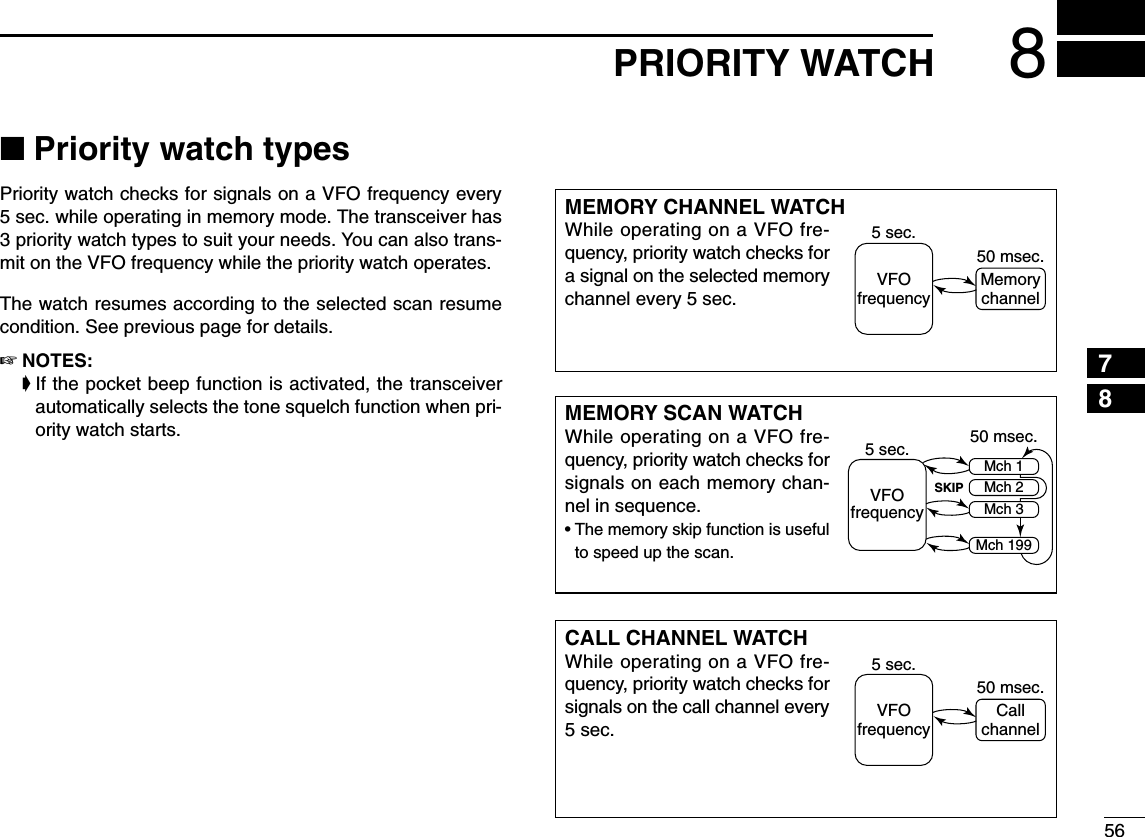
![578PRIORITY WATCH■Priority watch operationqSelect VFO mode; then, set an operating frequency in thedesired MAIN band (left or right).wSet the watching channel(s).For memory channel watch:Select the desired memory channel.For memory scan watch:Select memory mode; then, push the same band’s[V/MHz•SCAN] for 1 sec. to start memory scan.For call channel watch:Select the desired call channel by pushing the sameband’s [M/CALL•MW] once or twice, then rotate the[DIAL].ePush and hold [LOW•PRIO] for 1 sec. to start the watch.•The transceiver checks the memory or call channel every 5 sec.•The watch resumes according to the selected scan resume con-dition. (p. ??)rPush and hold [LOW•PRIO] for 1 sec. to stop the watch.zSelect VFO mode; then, set the desired fre-quency.xSet the watching channel(s).For memory channel watch:Push [MR/CALL] then [Y] or [Z] to select the de-sired memory channel.For memory scan watch:Push [MR/CALL], then push [SCAN2] to start thememory scan.For call channel watch:Push [MR/CALL] for 1 sec. then push [Y] or [Z]to select the call channel.cPush [PRIO3(PTT-M)] to start the watch.•The transceiver checks the memory or call channelevery 5 sec.•The watch resumes according to the selected scan re-sume condition. (p. 45)•To resume the watch manually when paused, push[PRIO3(PTT-M)] or [CLRA(MW)].vTo stop the watch, push [CLRA(MW)] once (ortwice while watch is paused).PRIO3](https://usermanual.wiki/ICOM-orporated/297000/User-Guide-746386-Page-74.png)
![589DTMF MEMORY ENCODER12345678910111213141516171819■Programming a DTMF codeDTMF tones are used for autopatching, controlling otherequipment, etc. The transceiver has 16 DTMF memory chan-nels (d0–d#) for storage of often-used DTMF codes of up to24 digits.qPush [TONE•DTMF] for 1 sec..•Select the main band in advance, by pushing the desired band’s[MAIN•BAND], if necessary.wRotate [DIAL] to select the “AUTO TX”, then push[MAIN•BAND].eRotate the [DIAL] to select the ON, then push[MAIN•BAND].•“1” appears in place of the main band’s display.rRotate the [DIAL] to select the “DTMF memory”.tPush [MAIN•BAND] to enter the DTMF memory program-ming condition.•Rotate [DIAL] to select the desired DTMF channel.yPush [V/MHz•SCAN] (left band).uRotate the [DIAL] to select the desired code.iPush [M/CALL•MW] (left band)to select the next digit.•Pushing [V/MHz•SCAN] (left band) move the cursor backward.oRepeat the steps tand yto set the desired DTMF tonesequence.!0 Push [V/MHz•SCAN] (Right band’s) twiceto exit DTMFmemory programming condition.[EXAMPLE]: Programming “5428AB453” into DTMF memory channel “d4.”Push PushRotatePush for 1 sec.TONEDTMFBANDMAINBANDMAINRotateBANDMAINBANDMAINPush (Right band's) twice to back.Push then rotate V/MHzSCANRepeat the previous step until the desired code is entered.M/CALLMWV/MHzSCAN](https://usermanual.wiki/ICOM-orporated/297000/User-Guide-746386-Page-75.png)
![599DTMF MEMORY ENCODERDProgramming a DTMF code— via microphonezPush [FUNC] then [LOW6(DTMF)] to turn theDTMF encoder ON.•“d” appears in place of the main band’s 100 MHz digit.xPush [SETB(D-OFF)] to enter the DTMF memoryprogramming condition.cPush [Y] or [Z] to select the desired DTMFmemory channel.vPush the desired digit keys.•When the first digit is input, previous memory contentsare cleared automatically.•“E” stands for “MM” and “F” stands for “# .”•Push [Y]/[Z] and repeat this step if you make a mistake.•The S/RF indicator shows the digit group. The indicationincreases every 6 digits.bPush [VFO/LOCK] to exit the programming condition.•The [CLRA(MW)] key cannot be used to exit. If pushed, code “A”is input. Reprogram in such a case.DTMF[EXAMPLE]: Programming “5428AB453” into DTMF memory channel “d4.”MAINT XMMAINT XMMAINT XMMAINT XMMAINT XMMAINT XMMAINT XMPushPush PushPushPush then .](https://usermanual.wiki/ICOM-orporated/297000/User-Guide-746386-Page-76.png)
![609DTMF MEMORY ENCODER12345678910111213141516171819■Transmitting a DTMF codeDAutomatic transmission (DTMF memory)qPush and hold [TONE•DTMF] for 1 sec. to turn the “AUTOTX”ON.• “1” appears in place of the main band’s display.wRotate [DIAL] to select the “DTMF MEMORY,”then push[MAIN•BAND] to enter DTMF memory programming con-dition.eRotate [DIAL] to select the desired DTMF memory channelthen push [MAIN•BAND].rPush [V/MHz•SCAN] (Right band’s) to return VFO mode.tPush [PTT] to transmit the selected DTMF memory content.yPush and hold [TONE•DTMF] for 1 sec. , then turn the“AUTO TX”OFF to cancel the DTMF encoder.•When the DTMF encoder is turned ON continuously, each pushof the PTT transmits the previously selected DTMF code.zPush [FUNC] then [LOW6(DTMF)] to turn theDTMF memory encoder ON.•“d” appears in place of the main band’s 100 MHz digit.xPush [SETB(D-OFF)] to enter the DTMF memoryprogramming condition.cPush [Y] or [Z] to select the desired channel.vPush [PTT] to transmit the selected memory.•Exit the programming condition automatically.•Each push of [PTT] transmits the DTMF code.bPush [FUNC] then [SETB(D-OFF)] to cancel theDTMF memory encoder.•When the DTMF encoder is turned ON continuously,each push of the PTT transmits the previously se-lected DTMF code.DTransmitting a DTMF memory directlyzPush [FUNC] then [LOW6(DTMF)] to turn theDTMF memory encoder ON.•“d” appears in place of the main band’s 100 MHz digit.xPush [DTMF-S] to turn the DTMF memory di-rect selection ON.•The function indicator (microphone) lights green.cPush the desired DTMF channel.•“0” to “9” and “A” to “D” are available for DTMFmemory channels.•The selected DTMF code is automatically transmit-ted without pushing PTT.NOTE: When no DTMF code programmed chan-nel number is pushed, it transmits the relativeDTMF code as the manual transmission de-scribed in the next page.vPush [DTMF-S] again to deactivate the DTMFmemory direct selection.bPush [FUNC] then [SETB(D-OFF)] to cancelthe DTMF memory encoder.DTMF-SDTMF](https://usermanual.wiki/ICOM-orporated/297000/User-Guide-746386-Page-77.png)
![619DTMF MEMORY ENCODERDManual transmissionzDeactivate the DTMF memory encoder bypushing [FUNC] then [SETB(D-OFF)].xPush [DTMF-S] to turn the DTMF direct selec-tion ON.•The function indicator (microphone) lights green.cPush one of “0” to “9” and “A” to “F” keys mo-mentarily, then push the desired DTMF keys,0–9 and A to F.•A: [CLRA(MW)] B: [SETB(D-OFF)], C: [ENTC(T-OFF)] D: [SQLYD(MUTE)], E: [MM(TONE-1)] F: [SQLZ#(16KEY-L)]•Automatically transmits without pushing PTT.•The first code, one of “A” to “F,” is not transmitted.DTMF code transmission starts from the 2nd code.vPush [DTMF-S] again to deactivate the DTMFdirect selection.■DTMF speedThe rate at which DTMF memories send individual DTMFcharacters can be set to accommodate operating needs.qPush [FF•]to display the function guide.wPush [V/MHz•SCAN] (Right band’s) to enter MENUscreen.eRotate [DIAL] to select “DUP/TONE,” then push [MAINBAND].rRotate [DIAL] to select “DTMF SPEED,” then push [MAINBAND].tRotate the main band’s [DIAL] to select the desired speedas shown in the table below, then push [MAIN BAND].yPush [FF•]to exit MENU screen.cps=characters/secDTMF-SDISPLAY INTERVAL SPEED100 100 msec. 5.0 cps200 200 msec. 2.5 cps300 300 msec. 1.6 cps500 500 msec. 1.0 cps](https://usermanual.wiki/ICOM-orporated/297000/User-Guide-746386-Page-78.png)
![6310 DTMF MEMORY ENCODERDSetting tone squelchqPush [FF•]to display the function guide.wPush [V/MHz•SCAN] (Right band’s) to enter MENUscreen, then rotate main band’s [DIAL] to select“DUP/TONE” set mode.ePush [MAIN•BAND], then rotate [DIAL] to select “CTCSSTONE.”rPush [MAIN•BAND], then rotate [DIAL] to select the de-sired CTCSS tone frequency.•Each operating band and each memory channel have indepen-dent settings.•See page ?? for available tone frequencies table.tPush [V/MHz•SCAN] (Right band’s) to return to“DUP/TONE” set mode, or push [FF•]to return to fre-quency indication.DSetting DTCS code for DTCS squelch orbeepqPush [FF•]to display the function guide.wPush [V/MHz•SCAN] (Right band’s) to enter MENUscreen, then rotate main band’s [DIAL] to select“DUP/TONE” set mode.ePush [MAIN•BAND], then rotate [DIAL] to select “DTCSCODE.”rPush [MAIN•BAND], then rotate [DIAL] to select the de-sired DTCS code.•Each operating band and each memory channel have indepen-dent settings.•See page ?? for available DTCS code table.tPush [V/MHz•SCAN] (Right band’s) to return to“DUP/TONE” set mode, or push [FF•]to return to fre-quency indication.DTCS mode can be selected in “DTCS POLARITY” menu.(p. ??)DTCS code settingTone squelch frequency setting](https://usermanual.wiki/ICOM-orporated/297000/User-Guide-746386-Page-80.png)
![6410DTMF MEMORY ENCODER12345678910111213141516171819DSetting digital code for digital code squelchor beepqPush [FF•]to display the function guide, push the leftband’s [V/MHz•SCAN] (Right band’s) several times to se-lect DV mode.wPush [V/MHz•SCAN] to enter MENU screen, then rotatemain band’s [DIAL] to select “DV SET MODE.”ePush [MAIN•BAND], then rotate [DIAL] to select “DIGI-TAL CODE.”rPush [MAIN•BAND], then rotate [DIAL] to select the de-sired digital code. (0-99)•Each operating band and each memory channel have indepen-dent settings.tPush [V/MHz•SCAN] (Right band’s) to return to“DUP/TONE” set mode, or push [FF•]to return to fre-quency indication.DSetting the YOUR and MY call signs fordigital call sign squelch or beepSee page ?? for DV MODE OPERATION.CAUTION!: Use digital code squelch when operating withmore than 3 stations. Because the digital call sign squelchfunction recognizes “MY CALL SIGN,” the digital call signsquelch function can be used when operating with only onestation.NOTE:• The tone/DTCS code squelch opens sometimes whenother stations communicate with adjacent tone frequencyor DTCS code.Digital code setting■Digital code and digital call sign settingThe optional UT-123](https://usermanual.wiki/ICOM-orporated/297000/User-Guide-746386-Page-81.png)
![6510 DTMF MEMORY ENCODERNOTE: The DTCS squelch operation on sub band will notbe performed during DTCS transmission, due to the sameencoder/decoder circuit is used for both main and subbands. And the tone squelch operation on sub band maynot be performed correctly during DTCS transmission.■Tone/DTCS squelch operationThe tone or DTCS squelch opens only when receiving a sig-nal with the same pre-programmed subaudible tone or DTCScode, respectively.qSet the operating frequency in the main band.wProgram the CTCSS tone frequency or DTCS code in“DUP/TONE” set mode.•See p. ?? for programming details.ePush [TONE•DTMF] several times until “T SQL” or “DTCS”appears in the main band’s display.rWhen a signal with the matched tone is received, thesquelch opens and the signal can be heard.•When the received signal includes an unmatched tone, thesquelch does not open. However, the S/RF indicator shows thereceived signal strength.•To open the squelch manually, push and hold [DUP•MONI].tOperate the transceiver in the normal way (push [PTT] totransmit; release [PTT] to receive).yTo cancel the tone squelch, push [TONE•DTMF] severaltimes until “T SQL” or “DTCS” disappears.zSet the operating frequency.xProgram the CTCSS tone frequency or DTCScode in set mode.•See p. 53 for programming details.cPush [FUNC] then [SIMP9(TSQL)] or [HIGH4(DTCS)]to turn the tone squelch or DTCS squelch ON.vWhen a signal with the matched tone is re-ceived, the squelch opens and the signal can beheard.•When the received signal includes an unmatchedtone, the squelch does not open. However, the S/RFindicator shows the received signal strength.•To open the squelch manually, push [MONI1(BANK)].bOperate the transceiver in the normal way (push[PTT] to transmit; release [PTT] to receive.nTo cancel the tone squelch, push [FUNC] then[ENTC(T-OFF)].•“T SQL” or “DTCS” disappears TSQLDTCS](https://usermanual.wiki/ICOM-orporated/297000/User-Guide-746386-Page-82.png)
![6610DTMF MEMORY ENCODER12345678910111213141516171819■Digital code/digital call signsquelchqSet the desired operating frequency on DV mode, Digitalcode and MY CALL SIGN.wPush [TONE•DTMF] several times to activate the digitalcode or digital call sign squelch. (DSQL or CSQL)•Digital call sign squelch “DSQL,” Digital call sign beep “DSQL”, Digital code squelch “CSQL,” Digital code beep “CSQL ” andno tone operation are activated in order.eOperate the transceiver in the normal way.rWhen the received signal includes a matching callsign/code, the squelch opens and the signal can be heard.•When the received signal’s call sign/code does not match, digitalcall sign/digital code squelch does not open, however, the MUTEindicator shows signal strength.■Pocket beep operationqSet the desired operating frequency and the desired oper-ating mode.wSet the desired CTCSS tone, DTCS code, Digital call signor Digital code.ePush [TONE•DTMF] several times to select “T SQL ” or“DTCS ” appears.•When DV mode operation, push [TONE•DTMF] several timesto select “DSQL ” or “CSQL ” appears.rWhen a signal with the correct tone, code, digital call signor digital code is received, the transceiver emits beep tonesfor 30 sec. and blinks “.”tPush [PTT] to answer or push [MAIN•BAND] to stop thebeeps and blinking.Pocket beep DTCS beepDigital call sign pocket beep Digital code pocket beepDigital call sign pocket beep Digital code pocket beepDigital call sign squelch Digital code squelchThe optional UT-123](https://usermanual.wiki/ICOM-orporated/297000/User-Guide-746386-Page-83.png)
![6710 DTMF MEMORY ENCODERzSet the operating frequency.xProgram the CTCSS tone frequency or DTCScode in set mode.➥Push [SETB(D-OFF)] to enter set mode.➥Push [SETB(D-OFF)] or [ENTC(T-OFF)]several times until “Ct” for tone squelch or“dt” for DTCS squelch appears.•“T SQL” blinks when tone squelch (“Ct”), or“DTCS” blinks when DTCS squelch (“dt”) is se-lected.➥Push [Y]/[Z] to select the desired tone fre-quency or DTCS code.➥Push [SETB(D-OFF)] to select “dtP” thenpush [Y]/[Z] to select the DTCS polarity.➥Push [CLRA(MW)] to exit set mode.cPush [FUNC] then push [DUP+ 8(TSQLS)]or [MID5(DTCSS)] to turn ON the pocketbeep with tone squelch or DTCS squelch, re-spectively.vWhen a signal with the matched tone is re-ceived, the transceiver emits beep tones for30 sec. and blinks “S.”bPush [PTT] to answer or push [CLRA(MW)] tostop the beeps and blinking.•“S” disappears and cancels the pocket beepfunction automatically.nTo cancel the tone squelch or DTCS squelchfunction, push [FUNC] then [ENTC(T-OFF)]. •“T SQL” or “DTCS” disappears ■DTCS polarity settingqPush [FF•]to display the function guide.wPush [V/MHz•SCAN] (Right band’s) to enter MENUscreen, then rotate main band’s [DIAL] to select“DUP/TONE” set mode.ePush [MAIN•BAND], then rotate [DIAL] to select “DTCSPOLARITY.”rPush [MAIN•BAND], rotate [DIAL] to select the desiredDTCS polarity mode.• BOTH N: Normal phase is used for both TX and RX.(Default)• TN-RR : Normal phase is used for TX; Reverse phasefor RX.• TR-RN : Reverse phase is used for TX; Normal phasefor RX.• BOTH R: Reverse phase is used for both TX and RX.tPush [V/MHz•SCAN] (Right band’s) to return to“DUP/TONE” set mode, or push [FF•]to return to fre-quency indication.DTCS polarity settingTSQLSDTCSS](https://usermanual.wiki/ICOM-orporated/297000/User-Guide-746386-Page-84.png)
![6810DTMF MEMORY ENCODER12345678910111213141516171819■Tone scanBy monitoring a signal that is being operated with pocketbeep, tone or DTCS squelch function, you can determine thetone frequency or DTCS code necessary to open a squ elch.qSet the desired operating frequency or memory channel tobe checked for a tone frequency or code in the main band.wPush [TONE•DTMF] several times to select the tone type,tone squelch or DTCS, to be scanned.•Either “T SQL” or “DTCS” appears ePush the main band’s [V/MHz•SCAN] for 1 sec. to startthe tone scan.•To change the scanning direction, rotate [DIAL].rWhen the CTCSS tone frequency or 3-digit DTCS code ismatched, the squelch opens and the tone frequency istemporarily programmed into the selected condition suchas memory or call channel.•The tone scan pauses when a CTCSS tone frequency or 3-digitDTCS code is detected.•The decoded CTCSS tone frequency or 3-digit DTCS code isused for the tone encoder or tone encoder/decoder dependingon the selected tone condition or type in step w. -“T SQL” : CTCSS tone encoder/decoder-“DTCS” : DTCS tone encoder/decodertPush [V/MHz•SCAN] to stop the scan.zSet the frequency or memory channel to bechecked for a tone frequency.xSelects the tone type to be scanned.•Push [FUNC] then push; [SIMP9(TSQL)] for tonesquelch; [HIGH4(DTCS)] for DTCS squelch.cPush [FUNC] then [SCAN2(T-SCAN)] to startthe tone scan.vWhen the tone frequency is matched, thesquelch opens and the tone frequency is pro-grammed into the selected mode such asmemory or call channel.bPush [CLRA(MW)] to stop the scan.T-SCANDUO BAND TRANSCEIVER i2820MAINT XT SQLMMAINT XDTCSMDuring CTCSS frequency scan During DTCS code scan[V/MHz•SCAN]☞NOTE: The decoded tone frequency is programmed tem-porarily when a memory or call channel is selected. How-ever, this will be cleared when the memory/call channel isre-selected.](https://usermanual.wiki/ICOM-orporated/297000/User-Guide-746386-Page-85.png)
![69PAGER/CODE SQUELCH11■Pager functionThis function uses DTMF codes for paging and can be usedas a “message pager” to confirm you of a caller’s identificationeven when you leave the transceiver temporarily unattended.■Code programmingDDBefore programmingThe pager and code squelch functions require ID codes and agroup code. These codes are 3-digit DTMF codes and mustbe written into the code channels before operation.qDecide the ID code of each transceiver and a group codefor your group.wDecide whether you want to return to normal operation orcode squelch operation after a connection is made.eProgram the ID code, group code and transmit codes(other station’s codes) as below.DDCode channel assignment*Channel CP automatically memorizes an ID code when receiving apager call. The contents in channel CP cannot be changed manually.Pager selective code (push [PTT])Beep BeepBeep Answer back (manual)Beep BeepBeep Set both transceivers to eithercode squelch or non-coded operationCommunicationID OR CODE CHANNEL “RECEIVE ACCEPT” OR GROUP CODE NUMBER “RECEIVE INHIBIT”Your ID codeOther parties’ID codeGroup codeMemory space*01–6One of 1–6P“Receive accept” only“Receive inhibit” should be programmed in each channel.“Receive accept” must be programmed in one channel.“Receive inhibit” only.](https://usermanual.wiki/ICOM-orporated/297000/User-Guide-746386-Page-86.png)
![7011PAGER/CODE SQUELCH12345678910111213141516171819DDCode programmingYour ID code MUST be programmed into code channel C0.Up to 6 transmit codes (codes that you transmit) are pro-grammable into code channels, C1 to C5, if required.qPush [FF•]to display the function guide.wPush [V/MHz•SCAN] (Right band’s) to enter MENUscreen.•Rotate [DIAL] to select “DUP/TONE”, then push the main band’s[MAIN•BAND].eRotate [DIAL] to select “PGR CODE”, then push the[MAIN•BAND].rRotate [DIAL] to select code channel C0.•“C0” is your ID code and “C1” to “C5” are transmit codes.•Each transceiver should have a different ID code.tPush the [MAIN•BAND], then rotate [DIAL] to select thedesired 3-digit ID code (default: 000) via the keypad.•Push [M/CALL•MW] (Left band’s) to move the cursor right; push[V/MHz•SCAN] (Left band’s) to move the cursor left. yRotate [DIAL] to select a transmit code channel from C1 toC5, then push the [MAIN•BAND].uEnter the desired 3-digit transmit code via the keypad.•Push [M/CALL•MW] (Left band’s) to move the cursor right; push[V/MHz•SCAN] (Left band’s) to move the cursor left. iPush [V/MHz•SCAN] (Left band) to set the channel to “re-ceive inhibit” or “receive accept” ON and OFF.•When “receive inhibit” is set, “SKIP” appears.•Code channel C0 cannot be set as “receive inhibit.”•See the table for “receive accept” and “receive inhibit” details(p. SKIP channel).oRepeat steps yand ito set additional transmit codechannels, if desired.!0 Push [FF•]to exit MENU screen.•Receive accept/receive inhibit➥“Receive accept” (“SKIP” indicator does not appear) ac-cepts pager calls when the transceiver receives a signalwith a code the same as that in the code channel.➥“Receive inhibit” (“SKIP” indicator appears) ignores callseven when the transceiver receives a code the same asthat in the code channel. Transmit codes should thereforebe programmed for “receive inhibit,” otherwise the trans-ceiver will not reject unnecessary calls.](https://usermanual.wiki/ICOM-orporated/297000/User-Guide-746386-Page-87.png)
![7111 PAGER/CODE SQUELCH■Pager operationDCalling a specific stationqProgram the pager code channel in advance (p. 39).wSet the operating frequency.• Set the volume and squelch to the desired level as in normal op-eration.qPush [FF•]to display the function guide, then enter theMENU screen.ePush [MAIN•BAND] to select “DUP/TONE”, then selectthe “PGR/C-SQL”.eRotate [DIAL] to set the “PGR”, then push [MAIN•BAND].•“PGR” indicator appear in normal frequency mode.rSelect the desired 3-digit transmit code channel:➥Enter “PGR CODE” (the pager code selection mode)in “DUP/TONE” set mode.➥Rotate [DIAL] to select the desired pager code chan-nel.➥Push [FF•]to return to previous mode.tPush [PTT] to transmit the pager code.yWait for an answer back.•When the transceiver receives an answer back code, the func-tion display shows the other member’s ID or group code.uAfter confirming a connection, push [MAIN•BAND] to enterthe “PGR/C-SQL” set mode, then rotate [DIAL] to selectthe code squelch operation “C-SQL,” or non-selectivecalling system “OFF.”•DO NOT push any digit keys while code channels C0 to C5 aredisplayed, otherwise code channel contents will be changed.iCommunicate with the other party as normal: push [PTT]to transmit; release to receive.DWaiting for a call from a specific stationqSet the operating frequency.wEnter “PGR/C-SQL” set item in “DUP/TONE” set mode.➥Rotate [DIAL] to select “PGR” if “C-SQL” or “OFF” ap-pears.➥Push [FF•]to return to previous mode.•“PGR” indication appear. eWait for a call.•When receiving a call, the caller’s ID or group code appears asshown at next page.•DO NOT push any digit keys while code channels C0 to C5 aredisplayed, otherwise code channel contents will be changed.rPush [PTT] to send an answer back call and display theoperating frequency.tAfter confirming a connection, enter “PGR/C-SQL” setitem, then rotate [DIAL] to select the code squelchoperation “C-SQL,” or non-selective calling system “OFF.”](https://usermanual.wiki/ICOM-orporated/297000/User-Guide-746386-Page-88.png)
![7211PAGER/CODE SQUELCH12345678910111213141516171819•PERSONAL CALLSThis display appears when you are called with your ID codeand the calling station’s ID code is 123.•GROUP CALLSThis display appears when you are called with the groupcode, 888, and 888 has been programmed into code channelC5.•ERROR INFORMATIONWhen the transceiver receives an incomplete code, “E” andpreviously received code appear.■Code squelchWhen using code squelch you will only receive calls from sta-tions which know your ID or group code. A 3-digit code is senteach time [PTT] is pushed in order to open the receiving sta-tion’s code squelch prior to voice transmission.qSet the operating frequency.• Set the volume and squelch to the desired level as in normal op-eration.wPush [FF•]to display the function guide.wEnter “PGR/C-SQL” set item in “DUP/TONE” set mode,then push [MAIN•BAND].• Rotate [DIAL] to select “C-SQL,” if “PGR” or “OFF” appears.wEnter “PGR CODE” set item in “DUP/TONE” set mode,then push [MAIN•BAND].eSelect the desired transmit code channel:➥Rotate [DIAL] to select the desired code channel.➥Push [FF•]to return to previous mode.•“C-SQL.” indication apper.rOperate the transceiver in the normal way (push [PTT] totransmit; release [PTT] to receive).tTo cancel the code squelch, Enter “PGR/C-SQL” set item,then rotate [DIAL] to select “OFF”•100 MHz digit shows “1” when the function is cancelled.Previously received code.Code channel“CP” and “ ” blink.During channel number indication (described on page 16)To use these functions in channel number indication, thepager/code squelch setting must be programmed with othermemory contents before selecting channel number indication.](https://usermanual.wiki/ICOM-orporated/297000/User-Guide-746386-Page-89.png)
![73EXTERNAL DTMF REMOTE12External DTMF remore function can be remotely controlledusing DTMF signals on the sub band. To operate externalDTMF remote, a 144MHz or 430(440) MHz transceiver with aDTMF encoder is required.qSet the sub band frequency to receive a control signal(DTMF code).• The optional tone squelch function can be used for the sub bandto increase remote control reliability.(p. Tone squelch)wEnter “DUP/TONE”into MENU screen.eProgram a 3-digit password into “PGR CODE” the subband’s code channel 5, if desired.(p. ??)• The initial value of code channel 5 is “000 (default); receive ac-cept.” If you do not require the password, set the channel as “re-ceive inhibit.”rSelect the main band by pushing a tuning dial, then set thedesired frequency for operation.tPush and hold [TONE•DTMF], then rotate [DIAL] to select“REMOTE CONTROL”turn ON appears to select standby forthe remote control.yPush [MAIN•BAND], then rotate [DIAL] to select ON• “” indicator appearuSet the operating frequency of the controller transceiverequal to the sub band frequency of the IC-2820H.• Make sure a tone frequency is set when using the optional tonesquelch function with the IC-2820H.• The external DTMF remote does not accept a control signal onthe main band frequency.iFrom the controller transceiver, transmit the DTMF codeas follows:oTo cancel standby for the remote control, push and hold[TONE•DTMF].• “” disappears.• Pushing [FUNC] then [SETB(D-OFF)] also cancels standby forthe remote control.• • • •Password(if programmed)Command(See example at right)B# B✽(or F) (or E)](https://usermanual.wiki/ICOM-orporated/297000/User-Guide-746386-Page-90.png)
![7412EXTERNAL DTMF REMOTE12345678910111213141516171819144.750 MHzMemory channel 15Scratch padmemory 2Password(if programmed)Frequency setting2 digits(or F) VFOmode[ENT] (UP) (or E)B 1 2 3 # 3 DCallchannel[DOWN] [DOWN]11 4VFOmode[ENT]2 D 1 5580VFOmode[ENT] 100MHz100kHz10kHz10MHz1 MHz3 D 14475#BDTMF KEYPAD[EXAMPLE]: Setting the opetating frequency to 145.8125 MHz (when the VHF tuning step is 12.5 kHz).1 2 3 A4 5 6 B7 8 9 C0 # DCALLDOWNMR VFOHIGHLOW1UP ENTCLR[EXAMPLE]Note for the [ENT] key• When the entered frequency is outside of the frequency coverage, the input digits will be cleared.• To adjust the frequency less than 10 kHz or to select a scan edge memory channel (1A, 1B), use the [UP] or [DOWN] key.](https://usermanual.wiki/ICOM-orporated/297000/User-Guide-746386-Page-91.png)
![75DIGITAL MODE OPERATION (Optional UT-123 is required )13■Digital mode operationThe IC-91A*/91AD can be operated in digital voice mode andlow-speed data operation for both transmit and receive. It canalso be connected to a GPS receiver (compatible with an RS-232 output/NMEA format/4800 bps) and transmit/receive positiondata.*The optional UT-121 is required for the IC-91A.■Call sign programmingFour types of call sign memories are available; your own callsign “MY CALL SIGN,” other station call sign “YOUR CALLSIGN,” repeater call sign “RPT1 CALL SIGN” and “RPT2CALL SIGN.” “MY CALL SIGN” can store up to 6 call signs,“YOUR CALL SIGN” can store up to 60 call signs and“RPT1/2 CALL SIGN” can store up to 60 call signs, and eachcall sign can be programmed with up to 8 characters.DDYour own call sign programmingYour own call sign must be programmed for both digital voiceand low-speed data communications (including GPS transmis-sion).qSelect B band as the main band. (p. 14)wEnter “MY” in call sign set mode.•MY CALL SIGN screen is displayed.eRotate [DIAL]†to select the desired call sign memory,“M01” to “M06.” rPush [≈≈](6) to enter call sign programming mode.•The 1st digit blinks.tRotate [DIAL]†to select the desired character or code.•Push [A/a](3) to change the character group from “AB” (alpha-betical characters; capital letters), “12” (numbers) and “/” (sym-bols) in sequence.M01M01 † /MY CALL SIGNr:SET:SET:SEL:SEL:CUR:CURCLR:CLRCLR:CLRA/a:CHARA/a:CHARABM01M01 /:SET:BACK:SEL:EDITCLR:CLRMY CALL SIGNrMENU screen➪CALL SIGN➪MY(Push [MENU/LOCK]) (Rotate [DIAL]†, then push [ï](5)†.)Although [DIAL] and [ï](5) are used for description in thissection, [∫∫](2)/[√√](8) and [≈≈](6) are available instead of[DIAL] and [ï](5).](https://usermanual.wiki/ICOM-orporated/297000/User-Guide-746386-Page-92.png)
 to select 2nd digit, then rotate [DIAL]†to se-lect the desired character or code.•Push [≈≈](6) to move the cursor right; push [ΩΩ](4) to move thecursor left.•2nd digit blinks (1st digit stops blinking).uRepeat the steps tand yto enter your own call sign.•Up to a 8-digit of call sign can be set.•If an un-necessary character is entered, push [≈≈](6) or [ΩΩ](4) toselect the character, then push [CLR](1) to erase the selectedcharacter, or push and hold [CLR](1) for 1 sec. to erase all char-acters following the cursor.•When programming a note (Up to a 4-digit for operating radiotype or area, etc.), go to step i, otherwise go to step !0.iPush [≈≈](6) several times to set the cursor beside “/” indi-cation.oRepeat steps tto yto program the desired 4-characternote.!0 Push [ï](5) to store the programmed call sign with noteand returns to MY CALL SIGN screen.!1 Push [MENU/LOCK] to return to frequency indication.M01M01 MYCALL MYCALL /IC91 /IC91:SET:BACK:SEL:EDITCLR:CLRMY CALL SIGNMY CALL SIGNrM01M01 M† /MY CALL SIGNMY CALL SIGNr:SET:SET:SEL:SEL:CUR:CURCLR:CLRCLR:CLRA/a:CHARA/a:CHARAB](https://usermanual.wiki/ICOM-orporated/297000/User-Guide-746386-Page-93.png)
![7713 DV MODE OPERATION (Optional UT-123 is required)DDStation call sign programming Station call sign must be programmed for the specified sta-tion call as well as repeater operation in both digital voice andlow-speed data communications.qSelect B band as the main band. (p. 14)wEnter “UR” in call sign set mode. •YOUR CALL SIGN screen is displayed.eRotate [DIAL]†to select the desired call sign memory,“U01” to “U60.” rPush [≈≈](6) to enter call sign programming mode.•The 1st digit blinks.tRotate [DIAL]†to select the desired character or code.•Push [A/a](3) to change the character group from “AB” (alpha-betical characters; capital letters), “12” (numbers) and “/” (sym-bols) in sequence.yPush [≈≈](6) to select 2nd digit, then rotate [DIAL]†to se-lect the desired character or code.•Push [≈≈](6) to move the cursor right; push [ΩΩ](4) to move thecursor left.•2nd digit blinks (1st digit stops blinking).uRepeat the steps tand yto enter the desired station callsign.•Up to an 8-digit of call sign can be set.•If an un-necessary character is entered, push [≈≈](6) or [ΩΩ](4) toselect the character, then push [CLR](1) to erase the selectedcharacter, or push and hold [CLR](1) for 1 sec. to erase all char-acters following the cursor.iPush [ï](5) to store the programmed call sign and returnsto YOUR CALL SIGN screen.oPush [MENU/LOCK] to return to frequency indication.U01U01 STATION1 STATION1:SET:BACK:SEL:EDITCLR:CLRYOUR CALL SIGNrU01U01 AB S†:SET:SET:SEL:SEL:CUR:CURCLR:CLRCLR:CLRA/a:CHARA/a:CHAR0:CQ0:CQYOUR CALL SIGNYOUR CALL SIGNrU01U01 AB †:SET:SET:SEL:SEL:CUR:CURCLR:CLRCLR:CLRA/a:CHARA/a:CHAR0:CQ0:CQYOUR CALL SIGNYOUR CALL SIGNrU CQCQCQ CQCQCQ:SET:BACK:SEL:EDITCLR:CLRYOUR CALL SIGNYOUR CALL SIGNrMENU screen➪CALL SIGN➪UR(Push [MENU/LOCK]) (Rotate [DIAL]†, then push [ï](5)†.)](https://usermanual.wiki/ICOM-orporated/297000/User-Guide-746386-Page-94.png)
 to set “CQCQCQ,” and push [CQ](0) againto return to the previously stored call sign.✔For your informationThe IC-91A/91AD has call sign edit record function.When editing a call sign stored in a call sign memory, regularmemory or call channel, the default setting is to store theedited call sign into a blank channel automatically. (“FULL” isdisplayed when all call sign memory is programmed.)The edited call sign can be over-written when the setting ofthe EDIT RECORD is set to OFF or SELECT. (p. 95)However, you must manually over-write a programmed callsign in regular memory and call channels. (Temporary opera-tion without over-writing is possible.)](https://usermanual.wiki/ICOM-orporated/297000/User-Guide-746386-Page-95.png)
![7913 DV MODE OPERATION (Optional UT-123 is required)■Digital voice mode operationqSet the desired frequency in B band. (pgs. 14, 18)•Select output power, if desired. (p. 24)wSelect DV mode. (p. 21)eSet your own call sign for DV operation as follows.zEnter “MY” in call sign set mode.xRotate [DIAL]†to select the desired your own call signchannel (if you have programmed several call signs) thenpush [ï](5) to set the call sign and return to CALL SIGNscreen.•See page 34 for your own call sign programming details.rSet the desired call sign as described in “When calling thedesired station (p. 39)” or “When sending a CQ (p. 39).” tPush and hold [PTT] to transmit and speak into the micro-phone at normal voice level.•Tx/Rx indicator lights red and the RF meter shows the outputpower.yRelease [PTT] to return to receive.•The other station call sign will be received.•Received call signs can be stored into the received call recordautomatically. See page 93 for details.NOTE: The digital mode operation is vastly different fromFM mode. One of the differences is in digital mode thesquelch does not function as in FM mode. Changing thesquelch setting will not open it to hear the hiss of “WhiteNoise.” It only activates for digital squelch functions suchas CSQL (Digital code squelch) or DSQL (Digital call signsquelch).UR:UR:R1:R1:R2:NOT USE*R2:NOT USE*MY:MYCALLMY:MYCALL /IC91 /IC91CALL SIGNrMENU screen➪CALL SIGN➪MY(Push [MENU/LOCK]) (Rotate [DIAL]†, then push [ï](5)†.)](https://usermanual.wiki/ICOM-orporated/297000/User-Guide-746386-Page-96.png)
![8013DV MODE OPERATION (Optional UT-123 is required)12345678910131213141516171819DDWhen calling the desired stationContinued instruction from step xon page 38.cRotate [DIAL]†to select “UR,” then push [ï](5)†.•YOUR CALL SIGN screen is displayed.vRotate [DIAL]†to select the call sign channel in which de-sired station’s call sign is programmed.•See page 36 for station call sign programming details.bPush [ï](5) to set the station’s call sign and return toCALL SIGN screen.nPush [MENU/LOCK] to return to frequency indication.mPerform the instruction steps tand yon page 38.DDWhen sending a CQContinued instruction from step xon page 38.cRotate [DIAL]†to select “UR,” then push [ï](5)†.•YOUR CALL SIGN screen is displayed.vRotate [DIAL]†to select the call sign channel in which“CQCQCQ” is programmed.Or, select “U” then push [≈≈](6) and [CQ](0) in sequence toset “CQCQCQ.”bPush [ï](5) to set “CQCQCQ” as the call sign and returnto CALL SIGN screen.nPush [MENU/LOCK] to return to frequency indication.mPerform the instruction step tand yon page 38.UR:CQCQCQUR:CQCQCQR1:R1:R2:NOT USE*R2:NOT USE*MY:MYCALLMY:MYCALL /IC91 /IC91CALL SIGNrUR:STATION1UR:STATION1R1:R1:R2:NOT USE*R2:NOT USE*MY:MYCALLMY:MYCALL /IC91 /IC91CALL SIGNCALL SIGNr](https://usermanual.wiki/ICOM-orporated/297000/User-Guide-746386-Page-97.png)
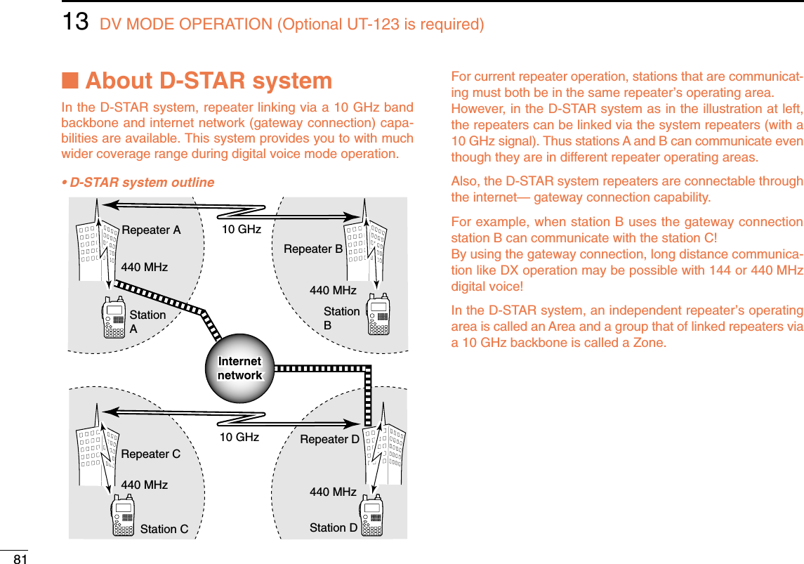
![8213DV MODE OPERATION (Optional UT-123 is required)12345678910131213141516171819■Digital repeater operationRepeater call signs must be programmed for repeater opera-tion in both digital voice and low-speed data communications.DDRepeater call sign programmingqSelect B band as the main band. (p. 14)wEnter “R1” or “R2” in call sign set mode. •RPT1 or RPT2 CALL SIGN screen is displayed.eRotate [DIAL]†to select the desired call sign memory,“R01” to “R60.” rPush [≈≈](6) to enter call sign programming mode.•The 1st digit blinks.tRotate [DIAL]†to select the desired character or code.•Push [A/a](3) to change the character group from “AB” (alpha-betical characters; capital letters), “12” (numbers) and “/” (sym-bols) in sequence.•Set “/” at the 1st digit then set the desired area repeater’s callsign (in a different zone) for CQ call (“/” stands for “CQCQCQ”) ina different zone operation. (p. 44)yPush [≈≈](6) to select 2nd digit, then rotate [DIAL]†to se-lect the desired character or code.•Push [≈≈](6) to move the cursor right; push [ΩΩ](4) to move thecursor left.•2nd digit blinks (1st digit stops blinking).uRepeat the steps tand yto enter the desired repeatercall sign.•Up to an 8-digit of call sign can be set.•Push [7] when setting with the gateway connection if the se-lected repeater has gateway capability. (The gateway connec-tion can be set in RPT1 only when “NOT USE✱” is set to RPT2.)•If an un-necessary character is entered, push [≈≈](6) or [ΩΩ](4) toselect the character, then push [CLR](1) to erase the selectedcharacter, or push and hold [CLR](1) for 1 sec. to all charactersfollowing the cursor.iPush [ï](5) to store the programmed call sign and returnsto RPT1 or RPT2 CALL SIGN screen.oPush [MENU/LOCK] to return to frequency indication.R01R01 RPT1AA G RPT1AA G:SET:BACK:SEL:EDITCLR:CLRRPT1 CALL SIGNrMENU screen➪CALL SIGN➪R1/R2(Push [MENU/LOCK]) (Rotate [DIAL]†, then push [ï](5)†.)](https://usermanual.wiki/ICOM-orporated/297000/User-Guide-746386-Page-99.png)
![8313 DV MODE OPERATION (Optional UT-123 is required)DDRepeater operation in the same zoneqSet the desired repeater’s frequency, offset and shift direc-tion in B band. (pgs. 18, 31)•Select DV mode in advance. (p. 21)wSet your own call sign. (p. 38)•See p. 34 for your own call sign programming.eSet the desired station call sign. (p. 39)•See p. 36 for station call sign programming.rSet the repeater’s call sign as follows;zEnter “R1” in call sign set mode.xRotate [DIAL]†to select the nearest repeater’s call sign.cPush [ï](5) to set the call sign for “R1.”•Return to CALL SIGN screen.vRotate [DIAL]†to select “R2” then push [ï](5)†.•RPT2 CALL SIGN screen is displayed.bRotate [DIAL]†to select the desired repeater’s (in thesame zone) call sign.•Select “NOT USE✱” when not operating RPT2.nPush [ï](5) to set the call sign for “R2.”•Return to CALL SIGN screen.mPush [MENU/LOCK] to return to frequency indication.tPush [PTT] to transmit; release to receive.UR:CQCQCQUR:CQCQCQR1:RPT1AAR1:RPT1AAR2:NOT USE*R2:NOT USE*MY:MYCALLMY:MYCALL /IC91 /IC91CALL SIGNCALL SIGNrMENU screen➪CALL SIGN➪R1(Push [MENU/LOCK]) (Rotate [DIAL]†, then push [ï](5)†.)](https://usermanual.wiki/ICOM-orporated/297000/User-Guide-746386-Page-100.png)
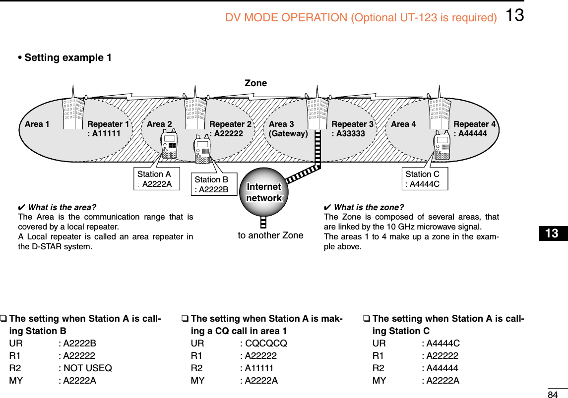
![8513 DV MODE OPERATION (Optional UT-123 is required)DDRepeater operation into another zoneqSet the desired repeater’s frequency, offset and shift direc-tion in B band. (pgs. 18, 31)•Select DV mode in advance.wSet your own call sign. (p. 38)•See p. 34 for your own call sign programming.eSet the desired station call sign. (p. 39)• When making a CQ callSet the desired repeater’s (in a different zone) call sign witha “/” symbol at the 1st digit, for the area in which youwant to make a CQ call, into “UR.”•See p. 36 for station call sign programming.rSet the repeater’s call sign as follows;zEnter “R1” in call sign set mode.xRotate [DIAL]†to select the nearest repeater’s call sign.•If the nearest repeater is gateway repeater, select the re-peater’s call sign with “G” setting at the 8th digit.cPush [ï](5) to set the call sign for “R1.”•Return to CALL SIGN screen.vRotate [DIAL]†to select “R2” then push [ï](5)†.bRotate [DIAL]†to select the gateway repeater’s (in thesame zone) call sign.•The call sign should have “G” setting at the 8th digit.•When gateway repeater call sign is set in “R1,” select “NOTUSE✱” for “R2” setting.nPush [ï](5) to set the call sign for “R2.”•Return to CALL SIGN screen.mPush [MENU/LOCK] to return to frequency indication.tPush [PTT] to transmit; release to receive.UR:CQCQCQUR:CQCQCQR1:RPT1AAR1:RPT1AAR2:NOT USE*R2:NOT USE*MY:MYCALLMY:MYCALL /IC91 /IC91CALL SIGNrMENU screen➪CALL SIGN➪R1(Push [MENU/LOCK]) (Rotate [DIAL]†, then push [ï](5)†.)](https://usermanual.wiki/ICOM-orporated/297000/User-Guide-746386-Page-102.png)
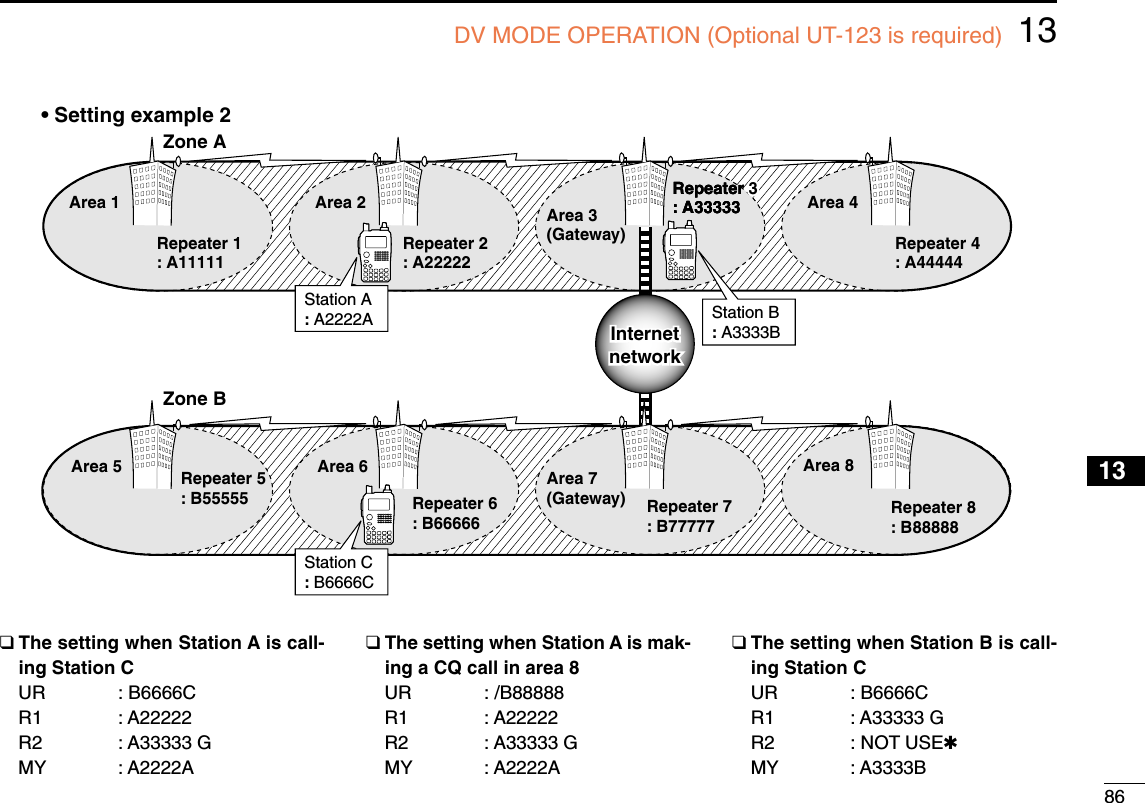
![8713 DV MODE OPERATION (Optional UT-123 is required)■Received call signWhen a call is received in DV mode, the calling station andthe repeater call signs being used can be stored into the re-ceived call record. The stored call signs are viewable in thefollowing manner.Up to 20 calls can be recorded.DDDesired call record indicationqEnter RX call sign set mode.•RX CALL SIGN screen is displayed.wRotate [DIAL]†to select the desired record channel.eTo confirm the received call, push [ï](5) several times toselect the desired call sign from CALLER, CALLED,RXRPT1 and RXRPT2.CALLER : The station call sign that made a call.CALLED : The station call sign called by the caller.RXRPT1 : The repeater call sign used by the caller station.RXRPT2 : The repeater call sign linked from RXRPT1.rPush [MENU/LOCK] to return to frequency indication.NOTE: When a call is received in DV mode when thepower save function is activated, the call sign may not bereceived correctly. This is normal, not a malfunction, because of header of thecall sign cannot be detected during power save.Turn the power save function OFF (p. 115) if you want toreceive a call sign correctly even in stand-by condition.✔For your informationWhen receiving a call, the received station call sign is auto-matically displayed and scrolled in sequence at the bottomline of the function display.This can be turned OFF in display set mode. (p.100)RX01RX01 CALLER: CALLER: AAAAAAAAAAAA /:CALLED :SEL:COPY CLR:CLRRX CALL SIGNrRX01RX01 CALLED: CALLED: CQCQCQCQCQCQ:RXRPT1 :SEL:COPY CLR:CLRRX CALL SIGNrRX01RX01 RXRPT2: RXRPT2: :CALLER :SEL:COPY CLR:CLRRX CALL SIGNrRX01RX01 RXRPT1: RXRPT1: :RXRPT2 :SEL:COPY CLR:CLRRX CALL SIGNrPush• Station call sign • Called station call sign• Repeater 1 call sign• Repeater 2 call signMENU screen➪RX CALL SIGN(Push [MENU/LOCK]) (Rotate [DIAL]†, then push [ï](5)†.)](https://usermanual.wiki/ICOM-orporated/297000/User-Guide-746386-Page-104.png)
 for1 sec.Or, while pushing and holding [RX➝CS](CALL), rotate[DIAL] to select the desired call sign record.•Set your own call sign (MY) in advance. (p. 34)•The call sign stored in “CALLER” is stored as “UR,” “RXRPT1” isstored as “R2” and “RXRPT2” is stored as “R1.”•Error beeps sound when a call sign is received incorrectly, andno call sign is set in this case.wPush [PTT] to transmit; release to receive.✔For your informationWhen a call specifying your call sign is received, the call signsof the calling station and the repeater it is using can be usedfor operation automatically.•When “RX call sign auto write” (p. 93) is set to “AUTO,” thestation call sign in “CALLER” is set to “UR” automatically.•When “Repeater call sign auto write” (p. 93) is set to “AUTO,”the stored station call sign in “RXRPT1” is stored as “R2”and “RXRPT2” is stored as “R1” automatically.Important!Setting call signs with the “One-touch reply using the callrecord” operation as at left are for temporary operation only.Therefore, the set call signs will be overwritten when an-other call record is used to set call signs.•Never saved into a call sign memory.If you want to save the set call signs, see “Copying the callrecord contents into call sign memory” (p. 50) for details.DVDVB439706-DUP-DUP25AAAAAAThe received call sign is displayed while pushing and holding [CALL/RX➝CS] when [DIAL] is rotated while [CALL/RX➝CS] is pushed.](https://usermanual.wiki/ICOM-orporated/297000/User-Guide-746386-Page-105.png)
![8913 DV MODE OPERATION (Optional UT-123 is required)■Copying the call signDDCopying the call sign memory contentsThis function is convenient when or modifying a part of thecurrent call sign.NOTE: Make sure that the “EDIT RECORD” item in DV setmode is set to “AUTO” or “SELECT” in advance. (p. 95)qDuring DV mode operation, enter call sign set mode.•CALL SIGN screen is displayed.wRotate [DIAL]†to select “UR,” “R1” or “R2” as desired, thenpush [ï](5)†.eRotate [DIAL]†to select the desired call sign channel to becopied.•U01–U60 and R01–R60 are available.• When “AUTO” is set to “EDIT RECORD” itemrPush [≈≈](6) to select the call sign programming mode.•A blank channel is selected automatically.•The 1st digit of the selected call sign blinks.tEdit or modify the selected call sign as described in “DSta-tion call sign programming” (p. 36) or “DRepeater call signprogramming” (p. 41).yPush [ï](5) to store the edited/modified call sign into theselected blank channel.NOTE: The message “FULL” is displayed when no blankchannel is available in station or repeater call sign mem-ory.Select the desired call sign channel number as describedin step uof “• When “SELECT” is set to “EDIT RECORD”item” at right-hand page in this case.U21U21 AB †AAAAAAAAAA:SET:SET:SEL:SEL:CUR:CURCLR:CLRCLR:CLRA/a:CHARA/a:CHAR0:CQ0:CQYOUR CALL SIGNYOUR CALL SIGNrA blank channelnumber blinks.MENU screen➪CALL SIGN(Push [MENU/LOCK]) (Rotate [DIAL]†, then push [ï](5)†.)](https://usermanual.wiki/ICOM-orporated/297000/User-Guide-746386-Page-106.png)
 to select the call sign programming mode.•The 1st digit of the selected call sign blinks.tEdit or modify the selected call sign as described in “DSta-tion call sign programming” (p. 36) or “DRepeater call signprogramming” (p. 41).yPush [ï](5).• Call sign channel number blinks.uRotate [DIAL]†to select the desired call sign channel tostore.iPush [ï](5) to store the edited/modified call sign into theselected channel.U21U21 ABAB AAAAA1 AAAAA1:SET:SET:SEL:SEL:CUR:CURCLR:CLRCLR:CLRA/a:CHARA/a:CHAR0:CQ0:CQYOUR CALL SIGNYOUR CALL SIGNrCall sign channelnumber bliks.](https://usermanual.wiki/ICOM-orporated/297000/User-Guide-746386-Page-107.png)
 to select copy select mode.•COPY SELECT screen is displayed.eRotate [DIAL]†to select the desired call sign to be copiedfrom “ALL,” “RXRPT1” and “RXRPT2.”•“ALL” selection won’t appear when either station or repeater callsign memory has no blank channel.• When “ALL” is selected➥Push [≈≈](6) to copy the selected record’s contents intothe appropriate call sign memory.•Returns to RX CALL SIGN screen automatically.• When “CALLER,” “RXRPT1” or “RXRPT2” is selectedzPush [≈≈](6) then rotate [DIAL]†to select the desired con-dition of call sign memory channel selection to be copied tofrom “AUTO” and “LIST SEL.”•“AUTO” selection won’t appear when the appropriate call signmemory has no blank channel.•Go to step rwhen “AUTO” is selected.xPush [≈≈](6), then select the desired call sign memorychannel to copy to with [DIAL].cPush [≈≈](6) to copy the call sign into the selected callsign memory.•Returns to RX CALL SIGN screen automatically.rPush [MENU/LOCK] to return to frequency indication.RX01RX01AUTOAUTOLIST SELLIST SEL:BACK:BACK:LIST:LISTCOPY SELECTCOPY SELECT:SEL:SELrRX01RX01ALL:BACK:BACK:LIST:LIST C:CURRC:CURRCOPY SELECTCOPY SELECT:SEL:SELr](https://usermanual.wiki/ICOM-orporated/297000/User-Guide-746386-Page-108.png)
 for 1 sec. to set the communi-cating station’s call sign.•When a call sign has not been received correctly, error beepssound and no call sign is set. Receive the call sign of a commu-nicating signal again, or set the call sign manually.wPush and hold [BK](9) for 1 sec. to turn the break-in func-tion ON.•“BK” appears.eWhen both stations are in standby, push [PTT] to transmita break-in call.•The programmed call sign station receives the break-in call aswell as your call sign.rWait for the reply call from the station who receives thebreak-in call.tAfter receiving the reply call, communicate normally.yTo cancel the break-in, push and hold [BK](9) for 1 sec. toturn OFF.BKBKDVDVBLOWLOWATTATT43071250 Appears• How to use the break-in?While operating with the call sign squelch (p. 110), thesquelch never opens (no audio sounds) even if a call is re-ceived, unless your own call sign (“MY”)is specified.However, when the call including the “BK ON” signal (break-in call) is received, the squelch will open and audio soundseven if the call is specified for another station.Station A Station BStation C• Station C calling to Station A with “BK OFF”Station A Station BStation C• Station C calling to Station A with “BK ON”Station A and B are communicating us-ing the call sign squelch.Station A and B are communicating us-ing the call sign squelch.Station B never hears that Station C is calling Station A.Station B also hears that Sta-tion C is calling Station A.](https://usermanual.wiki/ICOM-orporated/297000/User-Guide-746386-Page-109.png)
![9313 DV MODE OPERATION (Optional UT-123 is required)■Message operationDDTX message programmingTX messages are available for up to 5 channels and eachchannel can be programmed with a message of up to 20characters. Available characters are 0to 9, Ato Z(capital let-ters), ato z(lower case letters), some symbols and space.qEnter “TX MESSAGE” in message/position set mode.•TX MESSAGE screen is displayed.wRotate [DIAL]†to select the desired transmit messagechannel.•Ch01 to Ch05 and OFF are available.•Previously message is displayed if programmed.ePush [≈≈](6) to select the message edit condition.•The 1st digit of the message blinks.rRotate [DIAL]†to select the desired character or symbol.•Push [A/a](3) to change the character group from “AB” (alpha-betical characters; capital letters), “ab” (alphabetical characters;lower case letters), “12” (numbers) and “!”” (symbols) in se-quence.•If an un-necessary character is entered, push [≈≈](6) or [ΩΩ](4) toselect the character, then push [CLR](1) to erase the selectedcharacter, or push and hold [CLR](1) for 1 sec. to erase all char-acters following the cursor.tPush [≈≈](6) to select 2nd digit, then rotate [DIAL]†to selectthe desired character or code.•Push [≈≈](6) to move the cursor right; push [ΩΩ](4) to move thecursor left.•2nd digit blinks (1st digit stops blinking).yRepeat the steps rand tto enter the desired message.•Up to 20-character messages can be set.uPush [ï](5) to store the message.iPush [MENU/LOCK] to return to frequency indication.Ch01Ch01 †:SET:SET :SEL:SEL:BACK:BACKCLR:CLRCLR:CLRTX MESSAGETX MESSAGE:EDIT:EDITrCh01Ch01 †:SET:SET :SEL:SEL:BACK:BACKCLR:CLRCLR:CLRTX MESSAGETX MESSAGE:EDIT:EDITrMENU screen➪MESSAGE/POSITION➪TX MESSAGE(Push [MENU/LOCK]) (Rotate [DIAL]†, then push [ï](5)†.)](https://usermanual.wiki/ICOM-orporated/297000/User-Guide-746386-Page-110.png)
![9413DV MODE OPERATION (Optional UT-123 is required)12345678910131213141516171819DDMessage TransmissionSelect the message transmission function ON (Ch01–05) andOFF. When a message channel is selected, the transceivertransmits a text message (pre-programmed). (default: OFF) qSet the operating frequency, call signs and other settings,such as repeater, as desired in B band.wPerform the steps qto ein “DTX message program-ming” as at left.eRotate [DIAL]†to select the desired message channel.•“Ch01” to “Ch05” available.•See left-hand pages for message programming.rPush [ï](5) to set the message for transmission.tPush [PTT] to transmit the selected message.•The message is transmitted each time [PTT] is pushed.•The message is transmitted each 30 sec. automatically duringcontinuous transmission.yRelease [PTT] to return to receive.uWhen the reply call with a message is received, the callsign and the message scrolls at the bottom of the functiondisplay.✔For your informationThe automatic received call sign and/or message indicationcan be turned OFF in display set mode, if desired.➥RX CALL SIGN (p. 100)➥RX MESSAGE (p. 101)NOTE: Only 1 message can be stored in the IC-91A/91AD. The received message is cleared by turningpower OFF, or overwritten when another message is re-ceived.A transmitted message that includes lower case charac-ters from the IC-91A/91AD may not be decoded and dis-played correctly by the ID-800H, IC-V82/U82, etc.DVDVB43071250MSG:Hello!MSG:Hello!Scrolls the received message.](https://usermanual.wiki/ICOM-orporated/297000/User-Guide-746386-Page-111.png)
![9513 DV MODE OPERATION (Optional UT-123 is required)DDRX message indicationThe received message can also be checked in DV set mode.qSelect “RX MESSAGE” in message/position set mode.•The received message is displayed in RX MESSAGE screen.wRotate [DIAL] or push [√√](8) to display the station callsign.ePush [ï](5) or [ΩΩ](4) to return to MESSAGE/POSITIONscreen.rPush [MENU/LOCK] to return to frequency indication.■Automatic reply functionThe automatic reply function replies to calls by a station thatspecified your call sign.Two methods of replying are available— one is making areply call with your own call sign, and other one is making areply call with reply voice audio that has been recorded in DVvoice memory. DDAutomatic reply function settingqEnter “AUTO REPLY” in DV set mode. (p. 92)•AUTO REPLY screen is displayed.wRotate [DIAL]†to select the desired reply condition.OFF : Deactivate the automatic reply function. (default)ON : Reply to the call with your own call sign.VOICE : Reply to the call with the recorded voice memory.ePush [ï](5).•Returns to DV SET MODE screen automatically.rPush [MENU/LOCK] to return to frequency indication.OFFONVOICEVOICEAUTO REPLYrMENU screen➪DV SET MODE➪AUTO REPLY(Push [MENU/LOCK]) (Rotate [DIAL]†, then push [ï](5)†.)CALLER:CALLER: BBBBBB BBBBBB /:MSG:MSG:BACK:BACKRX MESSAGERX MESSAGErMESSAGE:MESSAGE:Hello!Hello!:CALLER:CALLER:BACK:BACKRX MESSAGERX MESSAGErMENU screen➪MESSAGE/POSITION➪RX MESSAGE(Push [MENU/LOCK]) (Rotate [DIAL]†, then push [ï](5)†.)](https://usermanual.wiki/ICOM-orporated/297000/User-Guide-746386-Page-112.png)
![9613DV MODE OPERATION (Optional UT-123 is required)12345678910131213141516171819DDVoice memory recording for automatic replyqSelect DV mode in B band, and deactivate the prioritywatch (p. 83) and weather alert function (p. 114) if activated.wEnter “REPLY VOICE” in DV voice memo set mode.•REPLY VOICE screen is displayed.eWhile pushing and holding [PTT], speak into the micro-phone.•Up to 10 seconds of message is recordable.•The recording stops after 10 second or when [PTT] is released.rPush [ΩΩ](4) to return to DV VOICE MEMO screen.tPush [MENU/LOCK] to return to frequency indication.DDPlay-back or erase the voice memoryqPush [MENU/LOCK] to select menu mode indication.wRotate [DIAL]†to select “DV VOICE MEMO,” then push[ï](5)†.eRotate [DIAL]†to select “REPLY VOICE,” then push[ï](5)†.•REPLY VOICE screen is displayed.rTo play-back the recorded voice memory, push [ï](5).•Push [ï](5) again to pause, push [≈≈](6) to cancel the play-back.tTo erase the recorded voice memory, push and hold[CLR](1) for 1 sec.REPLY VREPLY VPTT:PTT:●:BACK:BACK CLR:CLRCLR:CLRREPLY VOICEREPLY VOICE:rMENU screen➪DV VOICE MEMO➪REPLY VOICE(Push [MENU/LOCK]) (Rotate [DIAL]†, then push [ï](5)†.)IMPORTANT!Deactivate the dualwatch function and set minimum [VOL]level when recording the DV voice memo.Otherwise received audio or unwanted noise from A band isalso recorded into the voice memory.](https://usermanual.wiki/ICOM-orporated/297000/User-Guide-746386-Page-113.png)
 until 3 short and 1 long beepssound to turn the EMR setting ON.•“EMR” appearswOperate the transceiver normal way.eTo cancel the EMR communication mode, push and hold[EMR](.) for 1 sec. to turn OFF.■Low-speed data communicationIn addition to the digital voice communication, low-speed datacommunication is available.The optional OPC-1529R DATA COMMUNICATION CABLEand se-rial data communication software (purchase locally) are re-quired in addition.The optional RS-91 REMOTE CONTROL SOFTWARE(OPC-1529Rsupplied) also includes a low-speed data communication ca-pability.NOTE: Turn OFF the GPS mode (p. 58) in advance to op-erate the low-speed data communication.DDConnectionConnect the transceiver to your PC using with the optionalOPC-1529R as illustrated below.OPC-1529R(optional)to [DATA] toRS-232CEMREMRDVDVB43071250 Appears](https://usermanual.wiki/ICOM-orporated/297000/User-Guide-746386-Page-114.png)
![9813DV MODE OPERATION (Optional UT-123 is required)12345678910131213141516171819DDLow-speed data communication applicationsettingConfigure the low-speed data communication application asfollows.•Port : The same COM port number as IC-91A/91AD’s•Baud rate : 38.4 kbps (fixed value)•Data : 8 bit•Parity : None•Stop : 1 bit•Flow control : Xon/XoffDDLow-speed data communication operationNOTE: Confirm that in AUTO, the computer controls when[PTT] is activated to send data and the user doesn’t haveto operate the radio.qSet your own, station call signs, etc. as described in“■Digital voice mode operation” (p. 38) and “■Digital re-peater operation” (p. 41).wRefer to the instructions of the low-speed data communi-cation application.eTo transmit data •With your voice audio, push and hold [PTT] to transmit whilesending data from the PC. Release [PTT] to receive.•Under computer control, see Transmission condition setting atright.DDTransmission condition settingqEnter “DV DATA TX” in DV set mode. (p. 92)wRotate [DIAL]†to select “PTT” or “AUTO.”ePush [ï](5) (or [ΩΩ](4))to return to DV set mode, and push[MENU/LOCK] to return to frequency indication.MENU screen➪DV SET MODE➪DV DATA TX(Push [MENU/LOCK]) (Rotate [DIAL]†, then push [ï](5)†.)](https://usermanual.wiki/ICOM-orporated/297000/User-Guide-746386-Page-115.png)
![9913 DV MODE OPERATION (Optional UT-123 is required)■GPS operationDuring GPS mode operation, a GPS receiver (RS-232C out-put/NMEA format) can be connected to the [DATA] socket ofthe IC-91A/91AD to indicate the current position (Latitude andLongitude). The position data is transmitted with your voice sig-nals at the same time. In addition, the GPS message transmission is also availablefor the GPS mode operation.DDSentence formatter settingqEnter “GPS MODE” in DV set mode. (p. 94)•GPS MODE screen is displayed.wRotate [DIAL]†to select “ON.”ePush [ï](5)†to select GPS SENTENCE screen.rRotate [DIAL]†to select the desired GPS sentence, thenpush [ï](5).•A total 5 sentences, RMC, GGA, GLL, GSA and VTG are avail-able.tRotate [DIAL]†to turn the sentence usage ON and OFF.yPush [ï](5) (or [ΩΩ](4))to return to GPS SENTENCEscreen.uRepeat the steps rto yto set another GPS sentenceusage.•Up to 3 GPS sentences are usable at the same time.iPush [MENU/LOCK] to return to frequency indication.OFFOFFONGPS MODEGPS MODE:SENTENCE:SENTENCErMENU screen➪DV SET MODE➪GPS MODE(Push [MENU/LOCK]) (Rotate [DIAL]†, then push [ï](5)†.)OPC-1529R(optional)to [DATA] to RS-232C port(null modemadapter is required)GPSreceiver](https://usermanual.wiki/ICOM-orporated/297000/User-Guide-746386-Page-116.png)
 to select the message edit condition.•The 1st digit of the message blinks.eRotate [DIAL]†to select the desired character or symbol.•Push [A/a](3) to change the character group from “AB” (alpha-betical characters; capital letters), “ab” (alphabetical characters;lower case letters), “12” (numbers) and “!”” (symbols) in se-quence.rPush [≈≈](6) to select 2nd digit, then rotate [DIAL]†to selectthe desired character or code.•Push [≈≈](6) to move the cursor right; push [ΩΩ](4) to move thecursor left.•2nd digit blinks (1st digit stops blinking).tRepeat the steps rand tto enter the desired message.•Up to 20-character messages can be set.yPush [ï](5) to store the message.uPush [MENU/LOCK] to return to frequency indication.DATA: AB Hello!Hello!†:SET:SET:SEL:SEL:CUR:CURCLR:CLRCLR:CLRGPS MESSAGEGPS MESSAGEA/a:CHARA/a:CHARrDATA:DATA: AB †:SET:SET:SEL:SEL:CUR:CURCLR:CLRCLR:CLRGPS MESSAGEGPS MESSAGEA/a:CHARA/a:CHARrMENU screen➪MESSAGE/POSITION➪GPS(Push [MENU/LOCK]) (Rotate [DIAL]†, then push [ï](5)†.)](https://usermanual.wiki/ICOM-orporated/297000/User-Guide-746386-Page-117.png)
![10113 DV MODE OPERATION (Optional UT-123 is required)DDGPS message automatic transmission qEnter “GPS AUTO TX” in DV set mode. (p. 95)•GPS AUTO RX screen is displayed.wRotate [DIAL]†to select the desired position data transmit-ting interval from 5 sec., 10 sec., 30 sec., 1 min., 3 min.,5 min., 10 min., 30 min. and OFF.•The position data is transmitted only when [PTT] is pushed withOFF setting, the data is transmitted automatically once every5 sec., 10 sec., 30 sec., 1 min., 3 min., 5 min., 10 min. and30 min. when the appropriate setting is selected.•The GPS message is also transmitted if programmed.ePush [ï](5) (or [ΩΩ](4))to return to DV SET MODE screen.rPush [MENU/LOCK] to return to frequency indication.NOTE: Your own call sign (“MY”) should be set to activatethe GPS automatic transmission. DDPosition indicationqEnter “POSITION” in message/position set mode.•GPS POSITION screen is displayed.wRotate [DIAL]†to select the received position data indica-tion.ePush [ï](5) (or [ΩΩ](4))to return to MESSAGE/POSITIONscreen.rPush [MENU/LOCK] to return to frequency indication.MY POSITIONMY POSITIONGPS POSITIONGPS POSITIONr34.56.789 N34.56.789 N123.45.678 E123.45.678 E:RX POS:RX POS:BACK:BACKMENU screen➪MESSAGE/POSITION➪POSITION(Push [MENU/LOCK]) (Rotate [DIAL]†, then push [ï](5)†.)OFFOFF5SEC5SEC10SEC10SEC30SEC30SEC1MIN1MINGPS AUTO TXGPS AUTO TXrMENU screen➪DV SET MODE➪GPS AUTO TX(Push [MENU/LOCK]) (Rotate [DIAL]†, then push [ï](5)†.)](https://usermanual.wiki/ICOM-orporated/297000/User-Guide-746386-Page-118.png)
 (or [ΩΩ](4))to return to MESSAGE/POSITIONscreen.ePush [MENU/LOCK] to return to frequency indication.DATA:DATA: Call from Call from Osaka! Osaka!:BACK:BACKRX GPS MESSAGERX GPS MESSAGErMENU screen➪MESSAGE/POSITION➪RX GPS(Push [MENU/LOCK]) (Rotate [DIAL]†, then push [ï](5)†.)](https://usermanual.wiki/ICOM-orporated/297000/User-Guide-746386-Page-119.png)
![10313 DV MODE OPERATION (Optional UT-123 is required)DDDV voice memoryThe IC-91A/91AD has a DV voice memory that records a total30 second (approx.) of received audio.The DV voice memory is divided into 2 tracks, 15 secondseach in a track, as the default setting.◆Recording received audioqSelect DV mode in B band, and deactivate the prioritywatch (p. 83) and weather alert function (p. 114) if activated.wWhile receiving a DV signal, push [REC].eRotate [DIAL] to select the desired track.•“✱” is displayed beside the track number when the selected trackhas been recorded.rPush [REC] to start recording.•Track counter (bar meter) is displayed during record.•The recording is paused automatically when the DV signal is in-terrupted or when the DV audio signal cannot be received cor-rectly. Re-starts the recording when the DV audio signal isreceived correctly. tPush [REC] again to stop recording.•The recording stops automatically when the track becomes full.◆Track size settingThe track size can be changed with the following instruction.qEnter “TRACK SIZE” in DV voice memo set mode.•TRACK SIZE screen is displayedwRotate [DIAL]†to select the desired track size.10S/3TRACK : Makes 3 tracks and 10 seconds audiocan be recorded in each track.15S/2TRACK : Makes 2 tracks and 15 seconds audiocan be recorded in each track.30S/1TRACK : Makes 1 track only and 30 seconds audiocan be recorded in a track.ePush [ï](5) (or [ΩΩ](4))to return to DV VOICE MEMOscreen.rPush [MENU/LOCK] to return to frequency indication.10S/3TRACK10S/3TRACK15S/2TRACK15S/2TRACK30S/1TRACK30S/1TRACKTRACK SIZETRACK SIZErMENU screen➪DV VOICE MEMO➪TRACK SIZE(Push [MENU/LOCK]) (Rotate [DIAL]†, then push [ï](5)†.)DVDVB44001250qREC TRACK:2REC TRACK:2■Other functions for DV mode operation](https://usermanual.wiki/ICOM-orporated/297000/User-Guide-746386-Page-120.png)
![10413DV MODE OPERATION (Optional UT-123 is required)12345678910131213141516171819◆Playing-back and erasing the recorded audioqSelect DV mode in B band, and deactivate the prioritywatch (p. 83) and weather alert function (p. 114) if activated.wEnter “TRACK” in DV voice memo set mode.•TRACK screen is displayedeRotate [DIAL]†to select the desired audio track to be play-back or erased.•“✱” is displayed beside the track number when the selected trackhas been recorded.rPush [ï](5) to play-back the recorded audio.•Push [ï](5) again to pause, push [≈≈](6) to stop play-back.tPush and hold [CLR](1) for 1 sec. to erase the recordedaudio.yPush [ΩΩ](4) to return to DV VOICE MEMO screen.uPush [MENU/LOCK] to return to frequency indication.DDDV automatic detectThe “DV” mode indicator blinks when a non-DV signal is re-ceived during DV mode operation. The IC-91A/91AD DV automatic detection monitors in FMmode when other than DV mode signal is received.qEnter “AUTO DETECT” in DV set mode. (p. 95)wRotate [DIAL]†to turn the DV automatic detect function ONand OFF.OFF : “DV” mode indicator blinks, however the trans-ceiver receives in DV mode even if non-DV modesignals are received.ON : “DV” mode indicator blinks and the transceivermonitors the signal in FM mode.ePush [ï](5) (or [ΩΩ](4))to return to DV SET MODE screenrPush [MENU/LOCK] to return to frequency indication.NOTE: The received FM audio may be distorted when re-ceiving an FM signal with DV automatic detect function.MENU screen➪DV SET MODE➪AUTO DETECT(Push [MENU/LOCK]) (Rotate [DIAL]†, then push [ï](5)†.)TRACK:1TRACK:1 *::SEL:SEL:BACK:BACK CLR:CLRCLR:CLRTRACKTRACKrMENU screen➪DV VOICE MEMO➪TRACK(Push [MENU/LOCK]) (Rotate [DIAL]†, then push [ï](5)†.)](https://usermanual.wiki/ICOM-orporated/297000/User-Guide-746386-Page-121.png)
![105OTHER FUNCTIONS14■GeneralMENU screen is used for programming infrequently changedvalues or conditions of functions.•Entering MENU screen and operationqPush [FF•]to display the function guide.wPush [V/MHz•SCAN](Right band’s) to enter MENU screen.eRotate the [DIAL] to select the desired menu group, thenpush [MAIN•BAND].rRotate the main band’s [DIAL] to select the desired item,then push [MAIN•BAND].tRotate the [DIAL] to select the desired condition or value,then push [MAIN•BAND].yPush [FF•]to return to frequency indication or push[V/MHz•SCAN](Right band’s) to return the back screen.zPush [BAND] to select the main band.xPush [SETB(D-OFF)] to enter set mode.cPush [SETB(D-OFF)] or [ENTC(T-OFF)] to selectthe desired item.vPush [Y] or [Z] to select the condition or value.bPush [CLRA(MW)] to exit set mode.■Menu list†Refer to the chapter 11 for detils.CALL SIGN†RX CALL SIGN†DV MESSAGE†DV VOICE MEMO†SET MODEDV SET MODESCANMENU————p. 93p. 93p. 93REF.DUP/TONE...DISPLAYSOUNDSDV GPSPACKETGPS SET MODEMENUp. 94p. 94p. 94p. 94p. 94p. 94REF.SETB](https://usermanual.wiki/ICOM-orporated/297000/User-Guide-746386-Page-122.png)
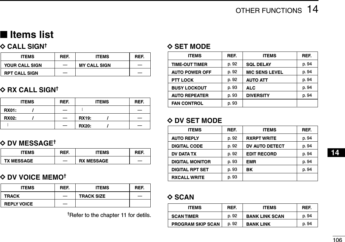
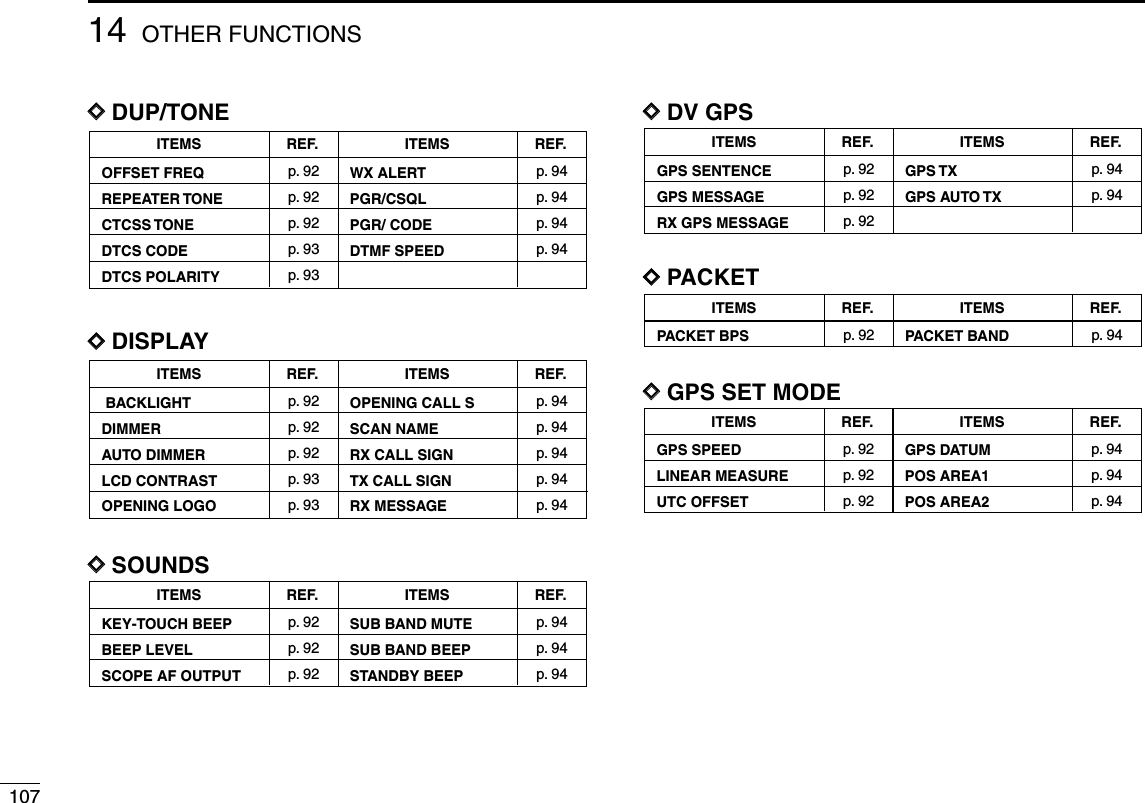

![10914 OTHER FUNCTIONS■SET MODE itemsDDTime-out timerTo prevent accidental prolonged transmission, etc., the trans-ceiver has a time-out timer. This function cuts a transmissionOFF after 1, 3 or 5 min. of continuous transmission. This timercan be cancelled.•OFF : The time-out timer is turned OFF. (default)•1, 3, 5 MIN : The transmission is cut OFF after the setperiod elapses.DDAuto power OFFThe transceiver can be set to automatically turn OFF after aspecified period with a beep when no key operations are per-formed.30 min, 60 min, 120 min and OFF (default) can be specified.The specified period is retained even when the transceiver isturned OFF by the auto power OFF function. To cancel thefunction, select “OFF” in this set mode.DDPTT lock Turns the PTT lock function ON and OFF(default.)Transmission with [PTT] is inhibited when ON is selected toprevent accidental transmission, etc.DDBusy lockoutTurns the busy lockout function ON and OFF(default.)This function inhibits transmission while receiving a signal orwhen the squelch is openDDAuto repeaterThe auto repeater function automatically turns ON or OFF theduplex operation and tone encoder. The offset and repeatertone is not changed by the auto repeater function. Resetthese frequencies, if necessary.U.S.A. version:•OFF : The auto repeater function is turned OFF.•RPT1 : Activates for duplex only. (default)•RPT2 : Activates for duplex and tone.Korean version:•OFF : Deactivates the function.•ON : Activates duplex and tone. (default)DDFan controlSelects the cooling fan control condition from AUTO, HI, MIDand LOW.•AUTO: The fan rotates during transmit and for 2 min.after transmission.(default)•HI : The high power fan continuously rotates.•MID : The middle power fan continuously rotates.•LOW : The low power.fan continuously rotates.U.S.A./KOREAN versions only](https://usermanual.wiki/ICOM-orporated/297000/User-Guide-746386-Page-126.png)
![11014OTHER FUNCTIONS12345678910111413141516171819DDSquelch delaySelects squelch delay from short and long to prevent re-peated opening and closing of the squelch during receptionof the same signal.•Short : Short squelch delay. (default)•Long : Long squelch delayDDMic sens levelSelects the microphone sensitivity from HIGH (default) andLOW to suit your preference.DDAuto ATTThe attenuator prevents distortion of a desired signal by verystrong RF signals near the desired frequency or when verystrong electric fields, such as from a broadcasting station, arepresent at your location.Select the attenuator function ON (default) and OFF.DDALCSets the ALC (automatic Level Control) function ON and OFF(default)The ALC function reduces the microphone again automati-cally when the transmission audio is distored.DDDiversityTurns the diversity function ON and OFF(default.).■DV SET MODE itemsThe following items are selectable by optional UT-123 is in-stalled into the IC-2820H.DDAuto replyThis function replies to an individual station call even you areaway from the transceiver.After a manual transmission (pushing [PTT]), the Auto Replysetting returns to OFF automatically.• OFF : No reply is performed even a call is received.(default)• ON : Sets caller’s call sign and reply to the call withthe set own call sign automatically.DDDigital codeSets the desired digital code for digital code squelch opera-tion. Total of 100 codes (0–99) are available. (default: 0)DDDV data TXDuring low-speed data operation, auto data transmissionfunction is available. This function transmits when data hasbeen input from PC via the [DATA] jack. (default: PTT)](https://usermanual.wiki/ICOM-orporated/297000/User-Guide-746386-Page-127.png)
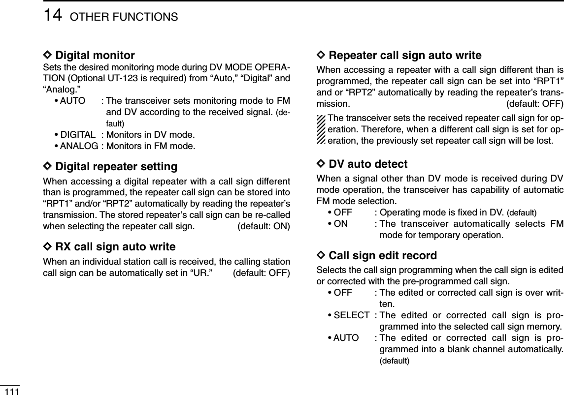
![11214OTHER FUNCTIONS12345678910111413141516171819DDEMR comunicationTurns the EMR comunication mode ON and OFF. (default)DDBreak-in comunicationTurns the break-in comunication mode ON and OFF. (default)■SCAN itemsDDScan timerSelects scan resume timer from T-15, T-10 (default), T-5 andP-2. •T-15/10/5 : Scan pauses for 15/10/5 sec., then resumes.•P-2 : Pause on a signal until signal disappears,then resumes 2 sec. after the signal disap-pears.DDProgram skip scanSets channel skip setting from ON (default) and OFF formemory skip scan operation. This item appears when set mode is accessed from memorymode only.DDBank link scanSets the memory bank link function ON (default) and OFF. Thelink function provides continuous bank scan, scanning all con-tents in the selected banks during bank scan.•Bank link settingqEnter MENU screen in function guide.wRotate the main band’s [DIAL] to select “SCAN” set mode,then push [MAIN•BAND].eRotate the [DIAL] to select “BANK LINK”, then push[MAIN•BAND] to enter bank setting.rRotate the [DIAL] to select the desired bank initial, thenpush [MAIN•BAND].tRotate [DIAL] to turn ON (default) and OFF, then push[MAIN•BAND].yRotate [DIAL] to select next bank and repeat steps rtot, or push [FF•] to exit scan set mode.](https://usermanual.wiki/ICOM-orporated/297000/User-Guide-746386-Page-129.png)
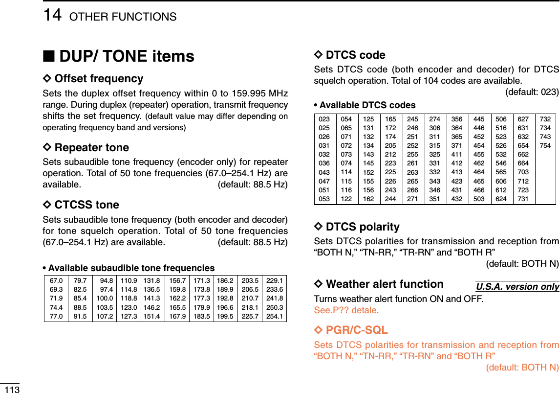
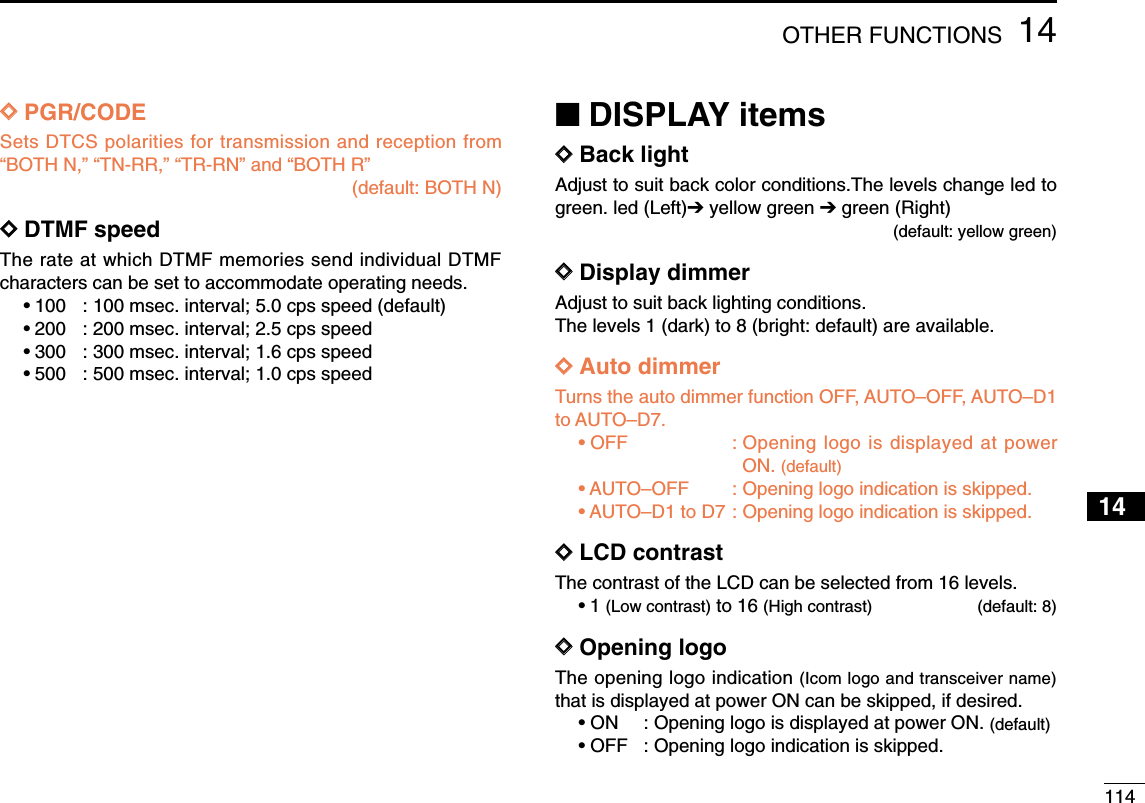
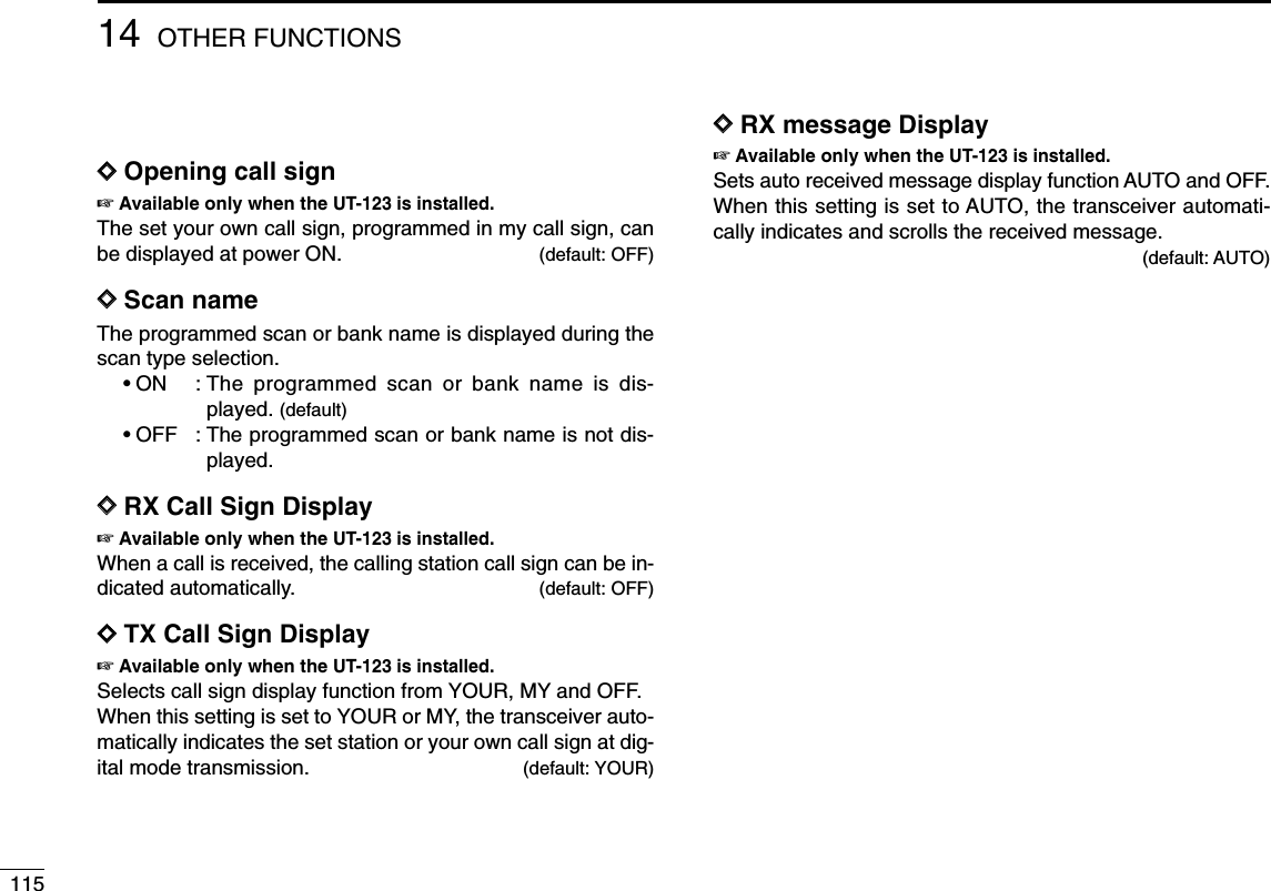
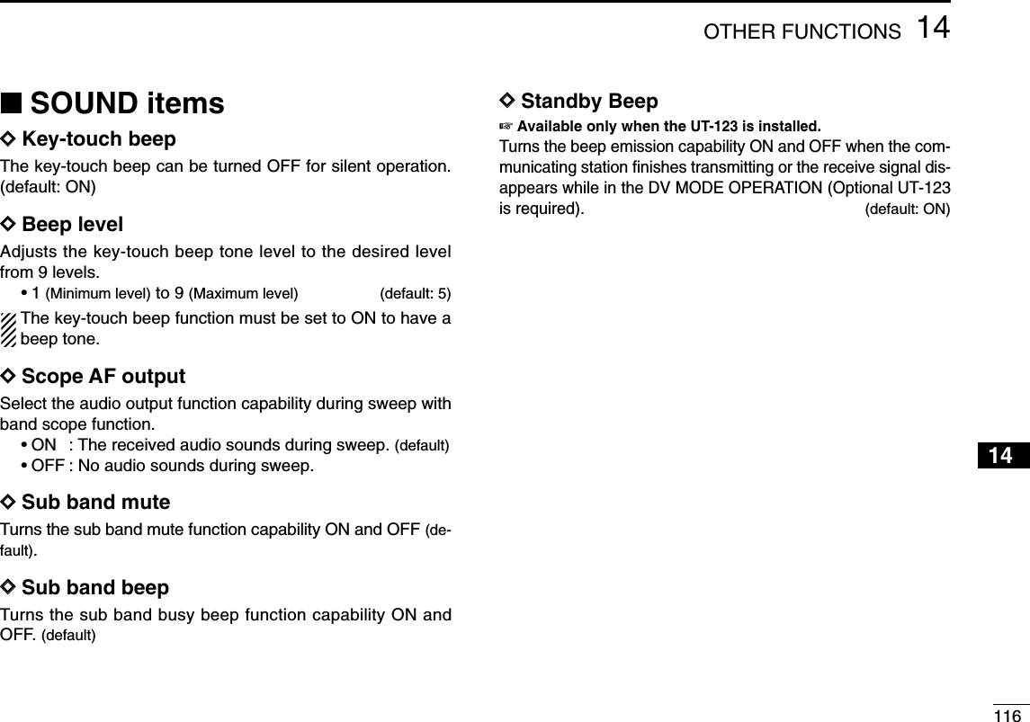
![11714 OTHER FUNCTIONS■DV GPS itemsDDGPS sentenceqEnter the MENU screen in the function guide.wRotate the main band’s [DIAL] to select “DV GPS,” thenpush the main band’s [MAIN•BAND] to enter the sentenceformatter selection.eRotate [DIAL] to select the desired sentence formatter.•RMC, GGA, GLL, GSA and VTG are selectable.rPush [MAIN•BAND] to enter the desired sentence format-ter selection.tRotate [DIAL] to select the setting, then push[MAIN•BAND]. yRotate [DIAL] to select next sentence and repeat steps eto t, or push [FF•] to return to frequency indication.•Only three sentence formatters can be activated at same time.DDGPS messageSee P?? to the chapter 13 for detils.DDRX GPS messageSelects the data transmission speed for packet operationfrom 1200 bps (default) and 9600 bps.DDGPS TXGPS transmission function select “ENABLE” or “DISABLE.”(default: ENABLE)DDGPS auto TXSelects the desired interval for automatic position transmis-sion function from 5, 10, 30 second, 1, 3, 5, 10 and 30 min-utes. (default: OFF)](https://usermanual.wiki/ICOM-orporated/297000/User-Guide-746386-Page-134.png)
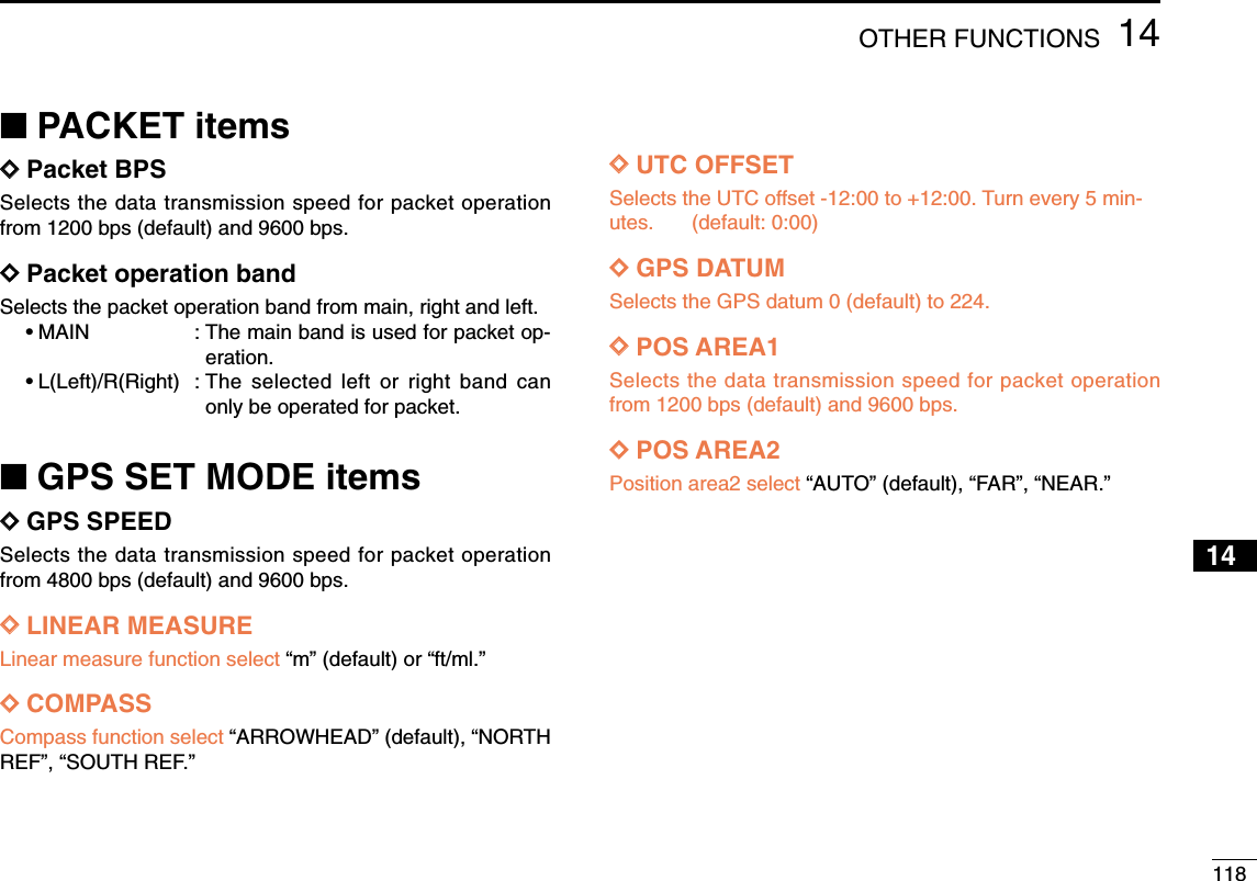
![11914 OTHER FUNCTIONSDDWeather channel selectionqPush the desired band’s [M/CALL•MW] several times toselect weather channel group. wRotate the same band’s [DIAL] to select the desiredweather channel. ePush the [M/CALL•MW] to select memory mode, or pushthe main band’s [V/MHz•SCAN] to select VFO mode.DDWeather alert functionNOAA broadcast stations transmit weather alert tones beforeimportant weather announcements. When the weather alertfunction is turned ON, the selected weather channel is moni-tored each 5 sec. for the announcement. When the alert sig-nal is detected, the “AL.t” and the WX channel are displayedalternately and sounds a beep tone until the transceiver is op-erated. The previously selected (used) weather channel ischecked periodically during standby or while scanning.qSelect the desired weather channel.wTurn the weather alert function ON in set mode.➥Push [FF•]to enter set mode.➥Push [FF•]or [LOW•PRIO] to select the weatheralert item, then rotate the [DIAL] to set ON.➥Push [TONE•DTMF] to exit set mode.eSets the desired stand-by condition.•Selects VFO, memory or call channel.•Scan or priority watch operation can also be selected.rWhen the alert is detected, a beep sounds and the follow-ing indication will be displayed.tTurn the weather alert function OFF in “DUP/TONE” setmode.☞NOTE: While receiving a signal (on a frequency other thanthe weather alert ON frequency), the receiving signal oraudio will be interrupted momentarily every 5 sec. (approx.)in case the alert function is turned ON. This symptom iscaused by the WX alert function. To cancel these symp-toms, set the weather alert item OFF in “DUP/TONE” setmode.BUSYMAINT XMBUSYMAINT XMShows above indications alternately.MAINT XMDUO BAND TRANSCEIVER i2820Weather channel group indicaiton[M/CALL•MW][DIAL]■Weather channel operation U.S.A. version only](https://usermanual.wiki/ICOM-orporated/297000/User-Guide-746386-Page-136.png)
![12014OTHER FUNCTIONS12345678910111413141516171819■Microphone keysThe supplied HM-133’s (optional for some versions) [F-1] and[F-2] keys memorize the transceiver conditions. The [UP]/[DN] keys of the standard or an optional microphone(other than the HM-133) can be assigned functions like thefunction keys on the transceiver’s front panel.DD[UP]/[DN] keys on a microphones(other than HM-133)The following functions are assigned to the [UP]/[DN] keys onthe other microphones (HM-118N/TAN, etc.) when first apply-ing power.•Default setting[UP] : channel up; push and hold to start scan, push againto stop scan.[DN] : channel down; push and hold to start scan, pushagain to stop scan.➥Assigning a functionqTurn the power OFF.wWhile pushing the desired key on the transceiver and oneof either [UP]/[DN] keys on the microphone, turn the powerON.•The function is programmed into the key.➥Clearing an assignmentqTurn the power OFF.wWhile pushing the desired [UP] or [DN] key on the micro-phone, turn the power ON.DD[F-1]/[F-2] keys on HM-133The following conditions in the main band or both left andright bands can be memorized into [F-1] and [F-2] keys, in-dependently.•Operating frequency•Repeater setting (offset direction and frequency, tone ON/OFFand frequency)•Tone/DTCS squelch (ON/OFF, frequency/code and polarity)•Transmit output power selection•Tuning step•Operating mode selection (FM/AM)•Set mode settings*•Initial set mode settings**Only when storing both bands conditions➥Programming the both bands conditionAfter setting the desired contents of eachcondition in the both bands, push [FUNC]then push [F-1]/[F-2] for 1 sec.•3 beeps sound.➥Recalling the both bands conditionPush [FUNC] then [F-1]/[F-2] momentarily.➥Programming the main band conditionSet the desired contents of each condition inthe main band, then push [F-1]/[F-2] for 1 sec.•3 beeps sound.➥Recalling the main band conditionPush [F-1]/[F-2] momentarily.[F-1]/[F-2]ATPOWER ON](https://usermanual.wiki/ICOM-orporated/297000/User-Guide-746386-Page-137.png)
![12114 OTHER FUNCTIONS■ALL resetThe function display may occasionally display erroneous in-formation (e.g. when first applying power). This may becaused externally by static electricity or by other factors.If this problem occurs, turn power OFF. After waiting a fewseconds, turn power ON again. If the problem persists, per-form the following procedure.•Partial resetting is also available. See left for details.IMPORTANT!:Resetting the transceiver CLEARS all memory informationand initializes all values in the transceiver.➥While pushing both band’s [M/CALL•MW], turn the powerON to reset the CPU.■Partial resetIf you want to initialize the operating conditions (VFO fre-quency, VFO settings, menu group’s contents) without clear-ing the memory contents, a partial resetting function isavailable for the transceiver left and right bands indepen-dently.➥While pushing desired band’s [V/MHz•SCAN], turn thepower ON to partially reset the desired band (left or right).✔Hint!When pushing both [V/MHz•SCAN] and turning the powerON, partially reset both bands at the same time.DUO BAND TRANSCEIVER i2820Left band partial reset.Right band partial reset.ATPOWER ON[M/CALL•MW]While pushing both [M/CALL•MW], turn power ON.[M/CALL•MW][PWR]ATPOWER ON](https://usermanual.wiki/ICOM-orporated/297000/User-Guide-746386-Page-138.png)
![12214OTHER FUNCTIONS12345678910111413141516171819■Data cloningCloning allows you to quickly and easily transfer the pro-grammed contents from one transceiver to another; or , datafrom a personal computer to a transceiver using the optionalCS-2820 CLONING SOFTWARE.DCloning between transceiversqConnect the OPC-474 cloning cable to the [SP-2] jack ofthe master and sub-transceivers.•The master transceiver is used to send data to the sub-trans-ceiver.wWhile pushing left band’s [M/CALL•MW], turn power ONto enter cloning mode (master transceiver only— power ononly for sub-transceiver).•“CLOnE” appears and the transceivers enter the clone standbycondition.ePush the same [M/CALL•MW] on the master transceiver.•“CLOnE OUt” appears in the master transceiver’s display andthe S/RF indicators show that data is being transferred to thesub-transceiver.•“CLOnE In” appears automatically in the sub-transceiver’s dis-play and the S/RF indicators show that data is being receivedfrom the master transceiver.rWhen cloning is finished, turn power OFF, then ON to exitcloning mode.MAINT XMAINT XMMDUO BAND TRANSCEIVER i2820Pushing left band’s [M/CALL•MW] start cloning.MAINT XMAINT XMMDUO BAND TRANSCEIVER i2820While pushing left band’s [M/CALL•MW], turn power ON.To [SP-2] To [SP-2]ATPOWER ON](https://usermanual.wiki/ICOM-orporated/297000/User-Guide-746386-Page-139.png)
![12314 OTHER FUNCTIONSDCloning using a personal computerData can be cloned to and from a personal computer (Mi-crosoft®Windows®98/2000/Me/XP) using the optional CS-2820 CLONING SOFTWAREand the optional cloning cableOPC-478U (USB type) or OPC-478 (RS-232C type). Consultthe CS-2820 CLONING SOFTWAREHELP file for details.DCloning error☞NOTE: DO NOT push any key on the sub-transceiver dur-ing cloning. This will cause a cloning error.When the display as below appears, a cloning error has oc-curred.In such a case, both transceivers automatically return to theclone standby condition and cloning must be repeated.■Packet operationDData speedFor packet operation, the transceiver can be set to one of twodata speeds: 1200 bps (default) or 9600 bps.qWhile pushing [FF•]turn power ON to enter initial setmode.wPush [FF•]or [LOW•PRIO] to select the ‘bPS’item.eRotate the left band [DIAL] to select the desired dataspeed.rPush [PWR] to exit initial set mode.For 1200 bps operation—•Disconnect the microphone plug from the microphoneconnector during data transmission, otherwise the datasignal and voice signal are simultaneously transmitted.For 9600 bps operation—•When the transceiver is set for 9600 bps data transmis-sion in set mode, the microphone signal is automaticallycut. Therefore, it is not necessary to disconnect the mi-crophone plug from the connector in this case.•When pushing [PTT] during data transmission, data trans-mission is interrupted and voice signals have priority.MAINT XMMAINT XMMAINT XMAINT XMM](https://usermanual.wiki/ICOM-orporated/297000/User-Guide-746386-Page-140.png)
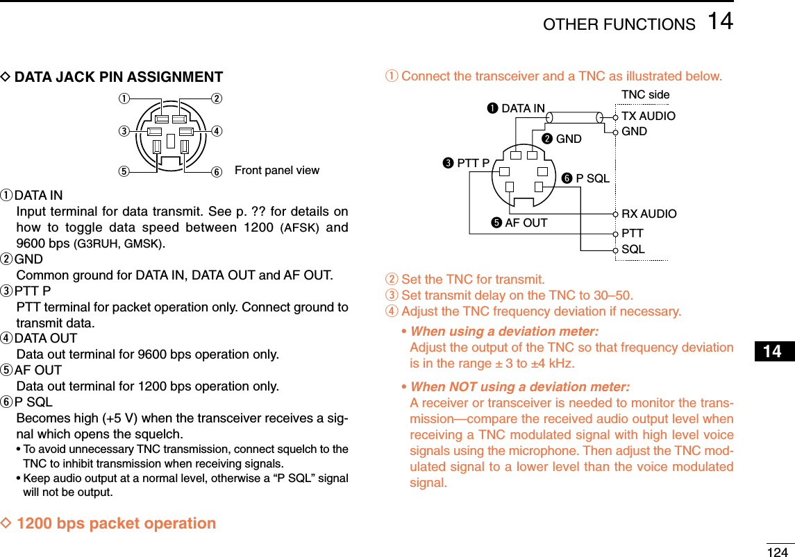
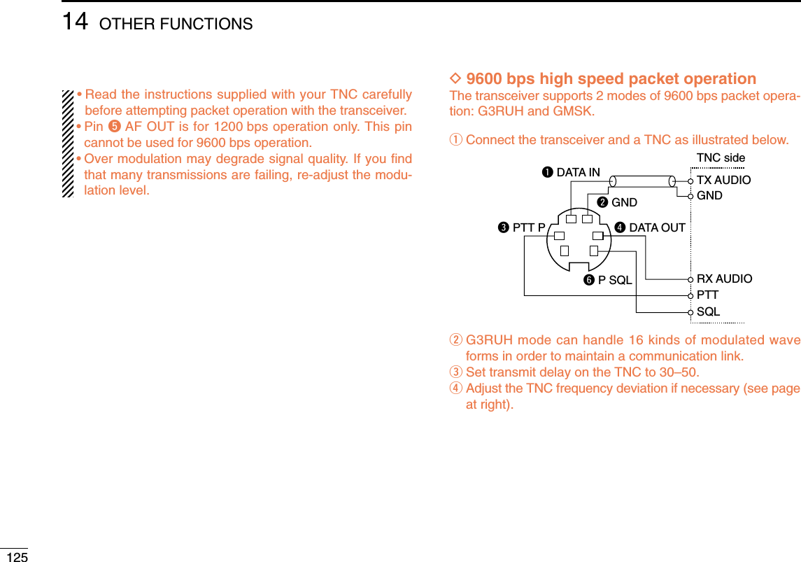
![12614OTHER FUNCTIONS12345678910111413141516171819•When using the PTT P terminal for packet operation, novoice signals are transmitted from the microphone.•When pushing [PTT] during data transmission, datatransmission is interrupted and the voice signal takes pri-ority.•Read the instructions supplied with your TNC carefullybefore attempting packet operation with the transceiver.•Pin rDATA OUT is for 9600 bps operation only. This pincannot be used for 1200 bps operation.DAdjusting the transmit signal output fromthe TNCWhen setting data transmission speed to 9600 bps, the datasignal coming from the TNC is applied exclusively to the in-ternal limiter circuitry to automatically maintain band width.NEVER apply data levels from the TNC of over 0.6 V p-p, oth-erwise the transceiver will not be able to maintain the bandwidth and may possibly interfere with other stations.1. When using a level meter or synchroscope, adjust theTX audio output level (DATA IN level) from the TNC asfollows.0.4 V p-p (0.2 V rms) : recommended level0.2 V p-p–0.5 V p-p (0.1–0.25 V rms) : acceptable level2. When NOT using a measuring device.qConnect the transceiver to a TNC.wEnter a test mode (“CAL”, etc.) on the TNC, then trans-mit some test data.eWhen the transceiver fails to transmit the test data ortransmits sporadically (TX indicator doesn’t appear orflashes):- Decrease the TNC output level until the transmit indi-cator lights continuously.When transmission is not successful even though theTX indicator lights continuously:- Increase the TNC output level.](https://usermanual.wiki/ICOM-orporated/297000/User-Guide-746386-Page-143.png)
![127MAINTENANCE13PROBLEM POSSIBLE CAUSE SOLUTION REF.■Troubleshooting If your transceiver seems to be malfunctioning, please checkthe following points before sending it to a service center.Does not turn on.No sound comes from thespeaker.Sensitivity is low and onlystrong signals are audible.No contact possible withanother station.Repeater cannot be ac-cessed. Frequency cannot be set.Frequency cannot be setvia the microphone.•Power connector has a poor contact.•Polarity of the power connection is reversed.•Blown fuse.•Volume is too low.•The audio mute function is activated.•Squelch is set too high.•A selective call or squelch function is activatedsuch as pocket beep or tone squelch.•Antenna feedline or the antenna connector has apoor contact or is short circuited.•Squelch attenuator function is activated.•The other station is using tone squelch.•The transceiver is set to duplex.•Wrong offset frequency is programmed.•Wrong subaudible tone frequency is programmed.•The frequency lock function is activated.•Priority watch is paused on the watching frequency.•The frequency lock function is activated.•The microphone keypad lock function is activated.•Priority watch is paused on the watching fre-quency.•Check the connector pins.•Re-connect the power cable observing the properpolarity. Replace the fuse if damaged.•Check the cause, then replace the fuse.•Rotate [VOL] clockwise.•Push any key to deactivate it.•Set the squelch level to the threshold.•Turn the appropriate function OFF.•Check, and if necessary, replace the feedline or sol-der the antenna connector again.•Set [SQL] between 10–12 o’clock position.•Turn the tone squelch function ON.•Set to simplex.•Correct the offset frequency.•Correct the subaudible tone frequency.•Turn the function OFF.•Push [LOW•PRIO] for 1 sec. to cancel the watch.•Turn the function OFF•Push [FUNC] then [sqlZ#(16KEY-L)] to deactivatethe microphone keypad lock function.•Push [LOW•PRIO] for 1 sec. to cancel the watch.—pgs. VI,74p. 74p. 16p. 21p. 16pgs. 52,53, 54p. VIIp. 17p. 54p. 23p. 27p. 25p. 15p. 47p. 15p. 15p. 47](https://usermanual.wiki/ICOM-orporated/297000/User-Guide-746386-Page-144.png)