ICOM orporated 297000 Scanning Receiver User Manual
ICOM Incorporated Scanning Receiver Users Manual
Users Manual
INSTRUCTION MANUAL
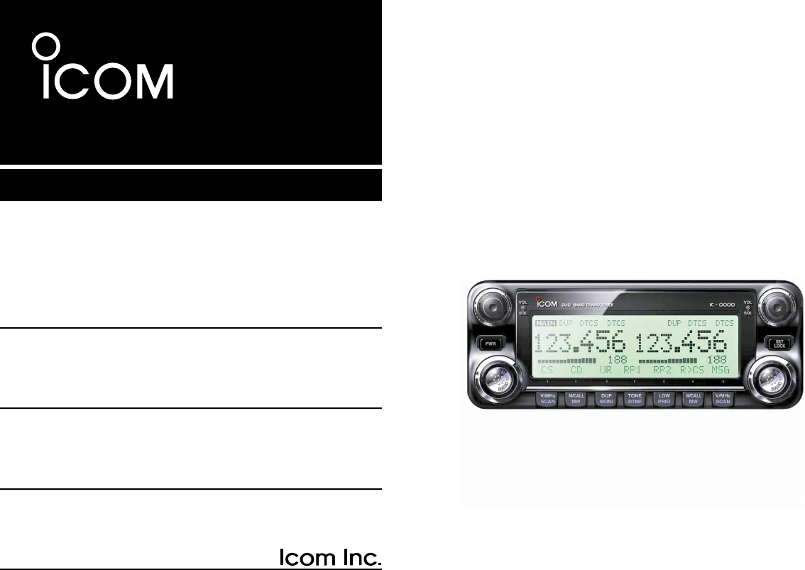
i2820H
DUAL BAND FM TRANSCEIVER
This device complies with Part 15 of the FCC rules. Operation is sub-
ject to the following two conditions: (1) This device may not cause
harmful interference, and (2) this device must accept any interference
received, including interference that may cause undesired operation.
i
FOREWORD
Thank you for purchasing this Icom product. The IC-2820H
VHF
/
UHF FM TRANSCEIVER
is designed and built with Icom’s su-
perior technology and craftsmanship. With proper care, this
product should provide you with years of trouble-free opera-
tion.
We want to take a couple of moments of your time to thank
you for making your IC-2820H your radio of choice, and hope
you agree with Icom’s philosophy of “technology first.” Many
hours of research and development went into the design of
your IC-2820H.
DD
FEATURES
❍Diversity reception is ready
❍DV (Digital Voice) with GPS operation
capabilities (Optional UT-123 is required)
❍V/V, U/U simultaneous receive capability
❍Independent controls for each left and right
bands
❍Separate controller for flexible installation
❍Remote control microphone standard
IMPORTANT
READ ALL INSTRUCTIONS carefully and completely
before using the transceiver.
SAVE THIS INSTRUCTION MANUAL— This in-
struction manual contains important operating instructions for
the IC-2820H.
EXPLICIT DEFINITIONS
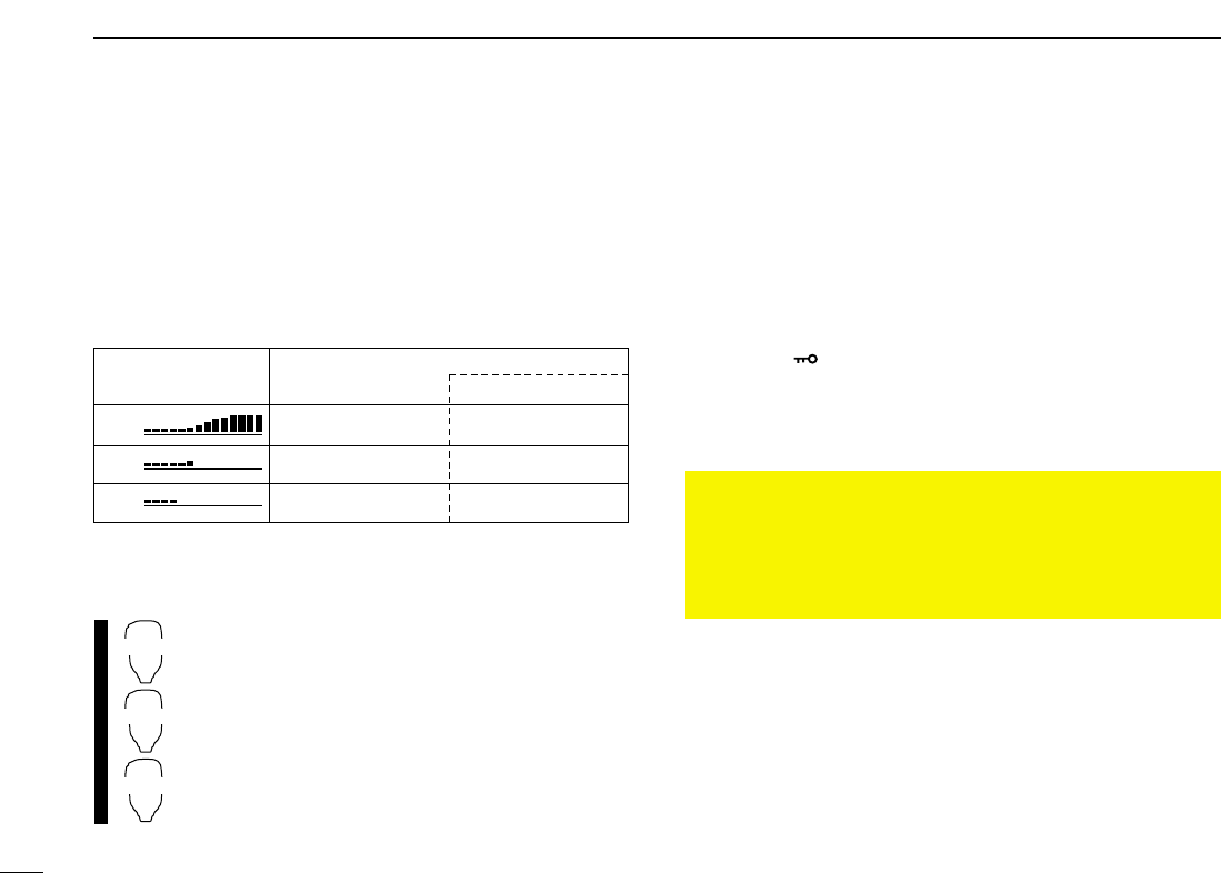
WORD DEFINITION
RWARNING!
CAUTION
NOTE
Personal injury, fire hazard or electric shock
may occur.
Equipment damage may occur.
Recommended for optimum use. No risk of
personal injury, fire or electric shock.
Icom, Icom Inc. and the logo are registered trademarks of Icom
Incorporated (Japan) in the United States, the United Kingdom, Ger-
many, France, Spain, Russia and/or other countries.

RWARNING RF EXPOSURE! This device emits Radio
Frequency (RF) energy. Extreme caution should be observed when
operating this device. If you have any questions regarding RF expo-
sure and safety standards please refer to the Federal Communica-
tions Commission Office of Engineering and Technology’s report on
Evaluating Compliance with FCC Guidelines for Human Radio fre-
quency Electromagnetic Fields (OET Bulletin 65).
RWARNING! NEVER connect the transceiver to an AC out-
let. This may pose a fire hazard or result in an electric shock.
RWARNING! NEVER operate the transceiver while driving a
vehicle. Safe driving requires your full attention—anything less may
result in an accident.
NEVER connect the transceiver to a power source of more than
16 V DC. This will damage the transceiver.
NEVER connect the transceiver to a power source using reverse
polarity. This will damage the transceiver.
NEVER cut the DC power cable between the DC plug and fuse
holder. If an incorrect connection is made after cutting, the transceiver
may be damaged.
NEVER expose the transceiver to rain, snow or any liquids. The
transceiver may be damaged.
NEVER operate or touch the transceiver with wet hands. This may
result in an electric shock or damage the transceiver.
NEVER place the transceiver where normal operation of the vehi-
cle may be hindered or where it could cause bodily injury.
NEVER let objects impede the operation of the cooling fan on the
rear panel.
DO NOT push the PTT when not actually desiring to transmit.
DO NOT allow children to play with any radio equipment contain-
ing a transmitter.
During mobile operation, DO NOT operate the transceiver with-
out running the vehicle’s engine. When the transceiver’s power is ON
and your vehicle’s engine is OFF, the vehicle’s battery will soon be-
come exhausted.
AVOID using or placing the transceiver in direct sunlight or in
areas with temperatures below –10°C or above +60°C.
BE CAREFUL! The transceiver will become hot when operat-
ing it continuously for long periods.
AVOID setting the transceiver in a place without adequate venti-
lation. Heat dissipation may be affected, and the transceiver may be
damaged.
AVOID the use of chemical agents such as benzine or alcohol
when cleaning, as they can damage the transceiver’s surfaces.
USE Icom microphones only (supplied or optional). Other manu-
facturer’s microphones have different pin assignments and may dam-
age the transceiver if attached.
For U.S.A. only
CAUTION: Changes or modifications to this device, not ex-
pressly approved by Icom Inc., could void your authority to
operate this device under FCC regulations.
ii
PRECAUTIONS
iii
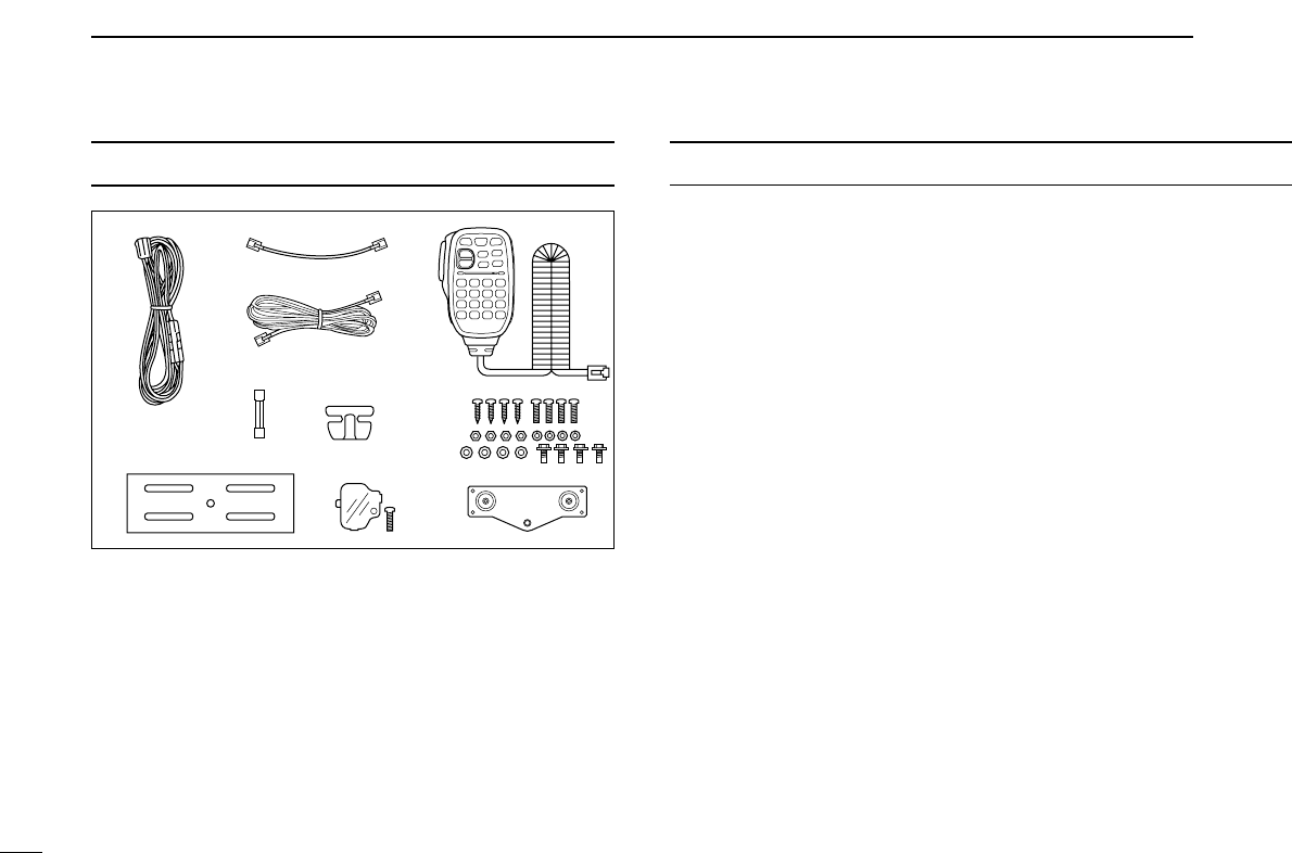
TABLE OF CONTENTSSUPPLIED ACCESSORIES
qDC power cable (3 m) ………………………………………1
wController cable (10 cm†; 3.9 in†) …………………………1
eSeparation cable (3.4 m†; 11.2 ft†) …………………………1
rMicrophone (HM-133)* ……………………………………1
tFuse (20 A) …………………………………………………1
yMicrophone hanger …………………………………………1
uMounting screws, nuts and washers …………………1 set
iMobile mounting bracket …………………………………1
oMicrophone connector plate with screw ……………1 set
!0Remote controller bracket …………………………………1
*HM-154
HAND MICROPHONE
may be supplied with some versions.
†Approx.
qw
e
t
r
i
u
!0o
y
FOREWORD ........................................................................................... i
IMPORTANT ............................................................................................ i
EXPLICIT DEFINITIONS ......................................................................... i
PRECAUTIONS ...................................................................................... ii
SUPPLIED ACCESSORIES .................................................................. iii
TABLE OF CONTENTS ......................................................................... iii
QUICK REFERENCE GUIDE ........................................................... I–XII
■Installation ....................................................................................... I
■Your first contact ......................................................................... VIII
■Repeater operation ........................................................................ X
■Programming memory channels.................................................... XI
1 PANEL DESCRIPTION ............................................................... 1–10
■Front panel— controller ................................................................. 1
■Function display ............................................................................. 3
■Main unit ........................................................................................ 5
■Microphone (HM-133) .................................................................... 7
■Microphone keypad ........................................................................ 8
■Optional microphones (HM-118N/TN/TAN)................................... 10
2 SETTING A FREQUENCY ........................................................ 11–15
■Preparation ................................................................................... 11
■Using the tuning dial .................................................................... 13
■Using the [Y]/[Z] keys ................................................................. 13
■Using the keypad ......................................................................... 13
■Tuning step selection ................................................................... 14
■Lock functions .............................................................................. 15
3 BASIC OPERATION ................................................................. 16–21
■Receiving ..................................................................................... 16
■Monitor function ........................................................................... 16
■Squelch attenuator ....................................................................... 17
■V/V, U/U simultaneous receive (Para-watch) ............................... 18
■Sub band mute/sub band busy beep ........................................... 19
■Transmitting ................................................................................. 20

1
2
3
4
5
6
7
8
9
10
11
12
13
14
15
16
17
18
19
iv
■Selecting output power ................................................................ 20
■One-touch PTT function ............................................................... 21
■Audio mute function ..................................................................... 21
4 REPEATER OPERATION ......................................................... 22–28
■General ........................................................................................ 22
■Accessing a repeater ................................................................... 23
■Subaudible tones ......................................................................... 25
■Offset frequency .......................................................................... 27
■Auto repeater (USA version only) ................................................ 28
5 MEMORY OPERATION ............................................................ 29–37
■General description ...................................................................... 29
■Memory channel selection ........................................................... 29
■Programming a memory channel ................................................. 30
■Transferring memory contents ..................................................... 32
■Memory clearing .......................................................................... 34
■Memory bank selection ................................................................ 35
■Memory bank setting .................................................................... 36
■Transferring bank contents .......................................................... 37
6 CALL CHANNEL OPERATION ................................................ 38–39
■Call channel selection .................................................................. 38
■Call channel transferring .............................................................. 38
■Programming a call channel ........................................................ 39
7 SCAN OPERATION .................................................................. 40–45
■Scan types ................................................................................... 40
■Scan start/stop ............................................................................. 41
■Scan edges programming ............................................................ 42
■Skip channel setting ..................................................................... 44
■Scan resume condition ................................................................ 45
8 PRIORITY WATCH .................................................................... 46–47
■Priority watch types ...................................................................... 46
■Priority watch operation ............................................................... 47
9 DTMF MEMORY ENCODER ..................................................... 48–51
■Programming a DTMF code ......................................................... 48
■Transmitting a DTMF code .......................................................... 50
■DTMF speed ................................................................................ 51
10 POCKET BEEP AND TONE SQUELCH ................................... 52–55
■Pocket beep operation ................................................................. 52
■Tone/DTCS squelch operation ..................................................... 54
■Tone scan ..................................................................................... 55
11 OTHER FUNCTIONS ................................................................ 56–72
■Set mode ...................................................................................... 56
■Initial set mode ............................................................................. 60
■AM/FM narrow mode ................................................................... 64
■Weather channel operation (USA version only) ........................... 65
■Microphone keys .......................................................................... 66
■Partial reset .................................................................................. 67
■All reset ........................................................................................ 67
■Data cloning ................................................................................. 68
■Packet operation .......................................................................... 69
12 MAINTENANCE ........................................................................ 73–74
■Troubleshooting ........................................................................... 73
■Fuse replacement ........................................................................ 74
13 SPECIFICATIONS AND OPTIONS ........................................... 75–76
■Specifications ............................................................................... 75
■Options ......................................................................................... 76
14 MODE ARRANGEMENT ........................................................... 77–78
I
QUICK REFERENCE GUIDE
■Installation
DPrecaution— magnets
RCAUTION
Magnets are used for the controller’s attachment to the main
unit.
NEVER hold the whole unit by the controller only when carry-
ing the transceiver. Carry the transceiver holding the main
unit. If held by the controller, the main unit may drop off and
may result in injury to the person carrying it or damage the
transceiver.
NEVER attach the controller on the main unit’s top cover, par-
ticularlly around the internal speaker grill. It may cause the
contents of the CPU and memory device could be deleted.
NEVER put the controller near a clock, television set (CRT
type), magnetic compass and any magnetic/IC cards, credit
cards, etc. It may cause the product to malfunction, and the
content of the magnetic card could be deleted.
Please note that the controller may drop off when a high im-
pact or vibration is applied.
DInstallation methods
• Single body installation
• The supplied mounting bracket can be used for the main
unit installation.
Transceiver
II
QUICK REFERENCE GUIDE
• Remote installation
•The supplied remote controller bracket and separation cable
can be used for installation.
•Optional OPC-1156
SEPARATION CABLE
(3.5 m; 11.5 ft) is
available for extend the separation cable.
•Optional OPC-440
MICROPHONE CABLE
(5.0 m; 16.4 ft) and
OPC-647 (2.5 m; 8.2 ft) are available to extend the micro-
phone cable.
•Optional OPC-441
SPEAKER CABLE
(5.0 m; 16.4 ft) is avail-
able to extend the speaker cable.
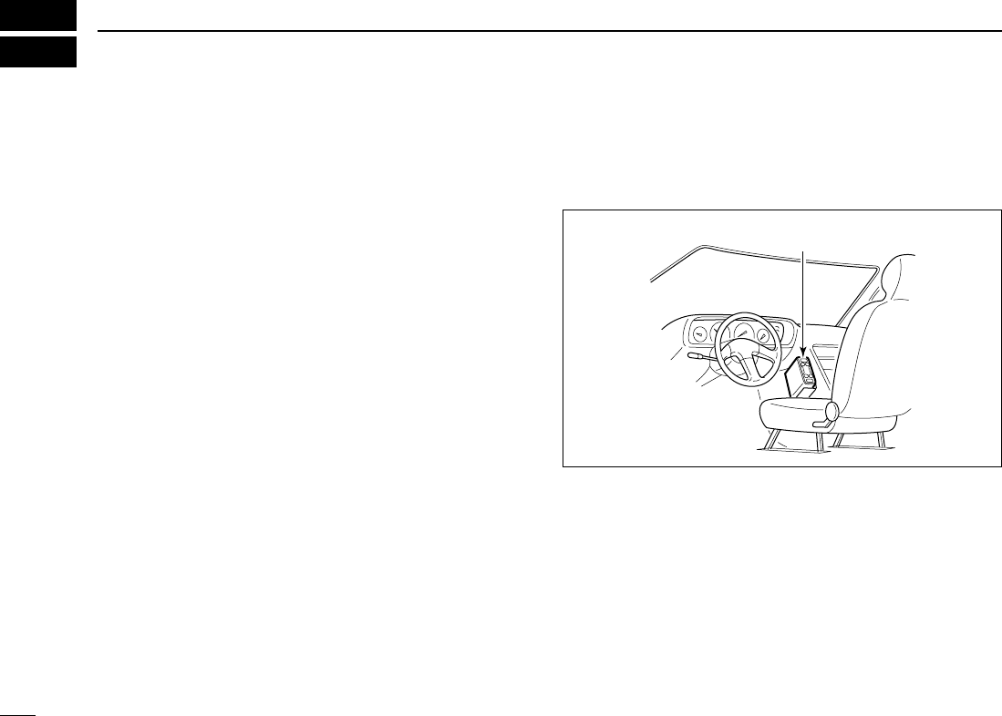
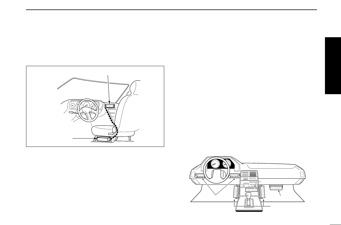
DLocation
Select a location which can support the weight of the trans-
ceiver and does not interfere with driving. We recommend the
locations shown in the diagram below.
NEVER place the transceiver or remote controller where nor-
mal operation of the vehicle may be hindered or where it
could cause bodily injury.
NEVER place the transceiver or remote controller where air
bag deployment may be obstructed.
DO NOT place the transceiver or remote controller where hot
or cold air blows directly onto it.
AVOID placing the transceiver or remote controller in direct
sunlight.
Controller
Main unit
Main unit
Main unit
Main body
Front panel
Quick reference guide
III
QUICK REFERENCE GUIDE
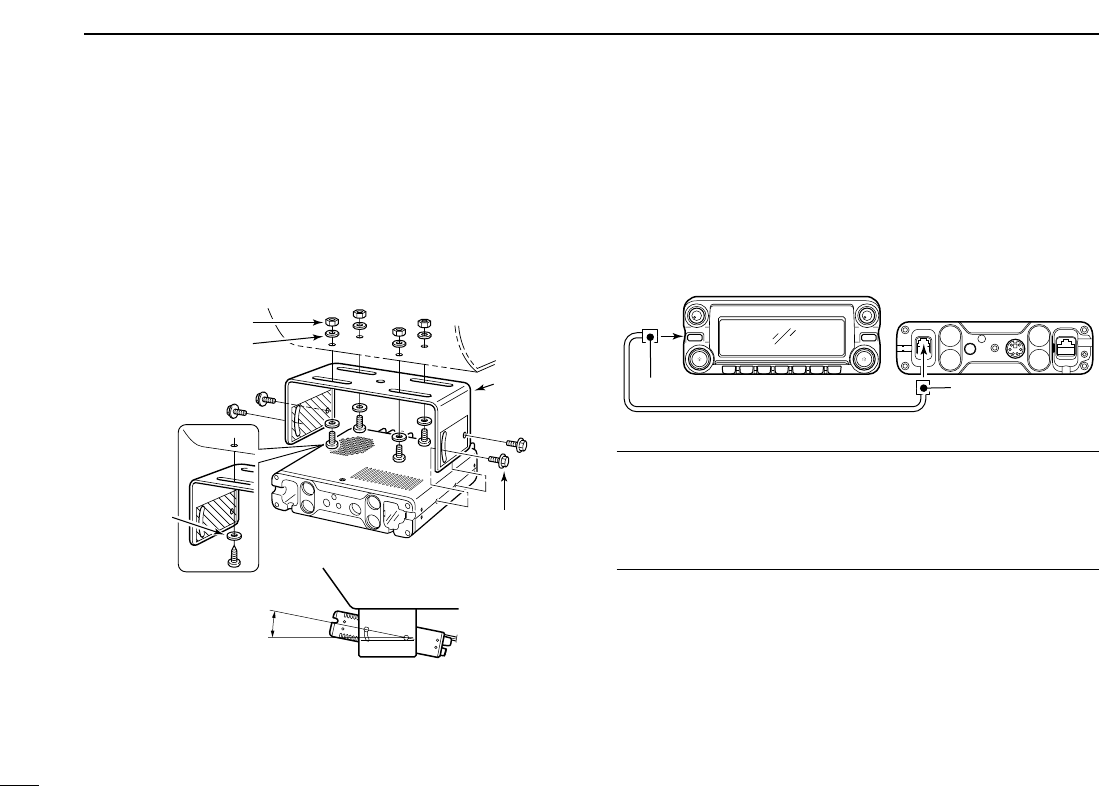
DUsing the mounting bracket
qDrill 4 holes where the mounting bracket is to be installed.
•Approx. 5.5–6 mm (1⁄4″) when using nuts; approx. 2–3 mm (1⁄8″)
when using self-tapping screws.
wInsert the supplied screws, nuts and washers through the
mounting bracket and tighten.
eAdjust the angle for your suitable position.
DController/Separation cable connection
Two connection cables, conteoller cable (10 cm; 3.9 in) for sin-
gle body installation and separation cable (3.4 m; 11.2 ft) for re-
mote installation, are supplied with the IC-2820H.
Connect the controller and the main unit using with the sup-
plied connection cable as follows.
IMPORTANT!— number of pin
Number of pin, between both side connectors of the connec-
tion cable are different— one side is 6-pin, other side is 4-pin.
You should connect the 6-pin connector to the main unit, and
the 4-pin connector to the controller.
Controller
Main unit
6-pin connector 4-pin connector
Nut
Spring washer
When using
self-tapping
screws
Flat washer Mounting nut
Mounting
bracket
25˚
IV
QUICK REFERENCE GUIDE
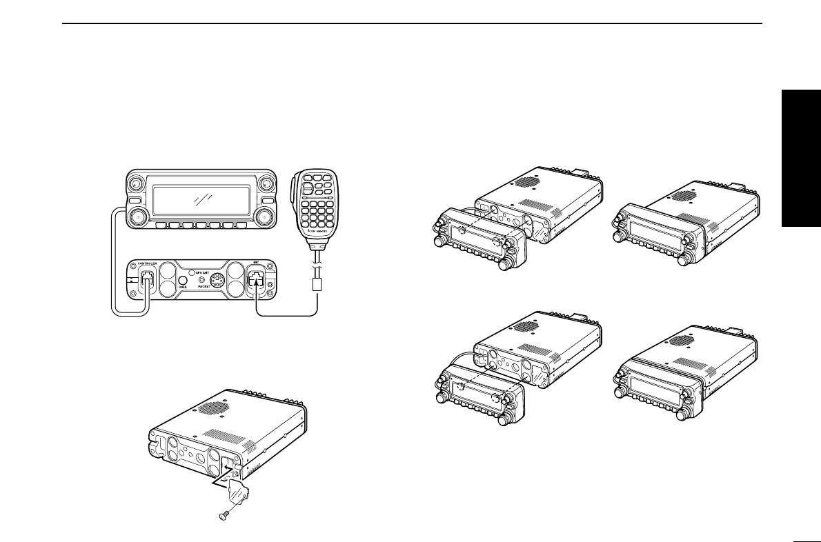
DMicrophone connection
A microphone connector is available on the main unit front
panel. Connect the supplied microphone connector as illus-
trated below.
Attach the supplied microphone connector plate after the mi-
crophone connection, otherwise the controller will easily
dropped off when the microphone cable is pulled during sin-
gle body installation.
DController’s attachment
You can attach the controller of the IC-2820H in one of 2
methods.
• Example 1
• Example 2
Controller Microphone
Main unit
Quick reference guide
V
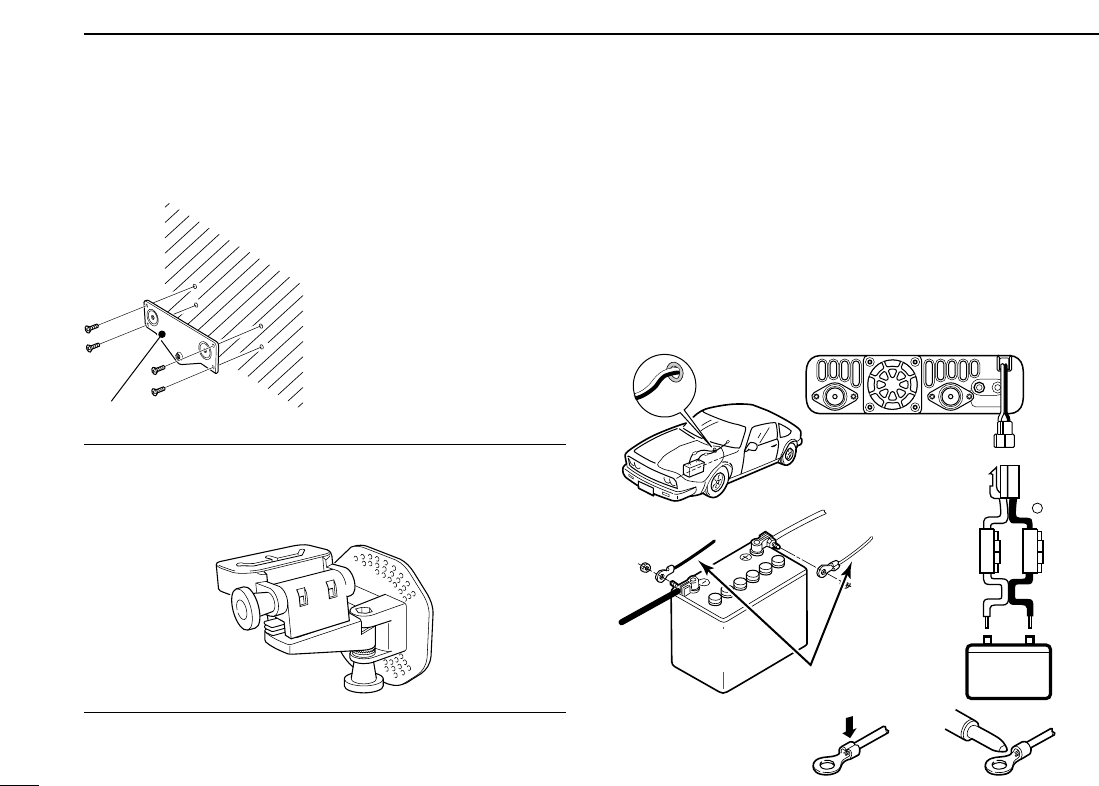
DRemote installation
The supplied remote controller bracket is used for remote in-
stallation.
• Attach the remote controller
bracket onto a flat surface
using with 4 self-tapping
screws (2.6 mm(d)), or double-
sticky tape, etc., as at left,
then attach remote controller
to the bracket
Hint!
The supplied remote controller bracket may fits to a mount-
ing angle, such as for car TV set as below. Ask your car ac-
cessory shop, if desired.
DBattery connection
☞RWARNING NEVER remove the fuse holders from the
DC power cable.
☞NEVER connect the transceiver directly to a 24 V battery.
☞DO NOT use the cigarette lighter socket for power con-
nections. (See p. ?? for details)
Attach a rubber grommet when passing the DC power cable
through a metal plate to prevent a short circuit.
• CONNECTING TO A DC POWER SOURCE
IC-2820H
Fuses
20 A
black
red⊕−
12 V
Grommet
NOTE:
Use terminals for the
cable connections.
WARNING!
NEVER
remove the
fuse holders.
Crimp Solder
12 V
battery Supplied
DC power cable
+ red
_ black
Remote controller bracket
QUICK REFERENCE GUIDE
VI
QUICK REFERENCE GUIDE
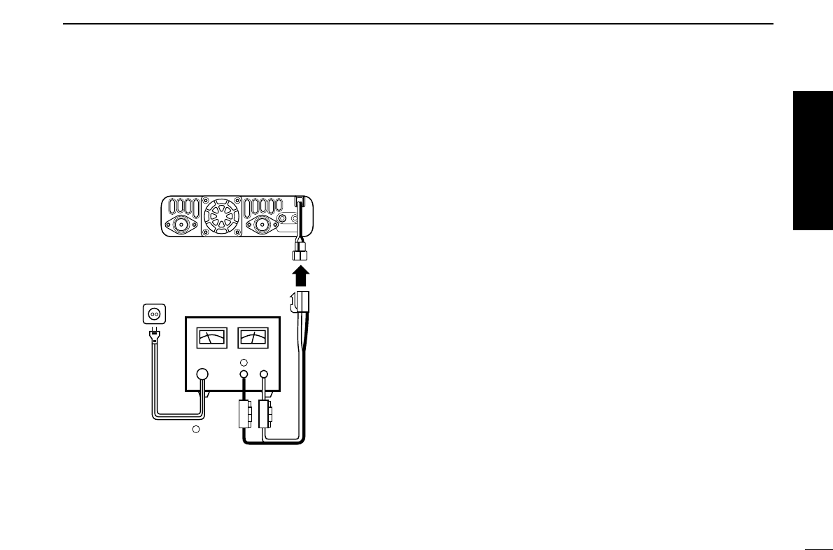
DDC power supply connection
Use a 13.8 V DC power supply with at least 15 A capacity.
Make sure the ground terminal of the DC power supply is
grounded.
• CONNECTING TO A DC POWER SUPPLY
See p. ?? for fuse replacement.
DC power
supply 13.8 V
to an
AC
outlet
Fuses
20 A
black
red⊕
−
⊕
−
IC-2820H
Quick reference guide
VII
QUICK REFERENCE GUIDE
DAntenna installation
•Antenna location
To obtain maximum performance from the transceiver, select
a high-quality antenna and mount it in a good location. It is
not necessary to use radials on a magnetic mount (“mag
mount”) antenna.
•Antenna connector
The antenna uses a PL-259 connector.
•PL-259 CONNECTOR
qSlide the coupling ring
down. Strip the cable
jacket and soft solder.
wStrip the cable as shown
at left. Soft solder the cen-
ter conductor.
eSlide the connector body
on and solder it.
rScrew the coupling ring
onto the connector body.
(10 mm ≈3⁄8 in)
NOTE: There are many publications covering proper an-
tennas and their installation. Check with your local dealer
for more information and recommendations.
30 mm
10 mm (soft solder)
10 mm
1–2 mm
solder solder
Soft
solder
Coupling ring
To antenna
for diversity
To antenna
for Tx/Rx
Roof-mount antenna
(Drill a hole or use a magnetic mount.)
Gutter-mount antenna
Trunk-mount
antenna
VIII
QUICK REFERENCE GUIDE
■Your first contact
Now that you have your IC-2820H installed in your car or
shack, you are probably excited to get on the air. We would
like to take you through a few basic operation steps to make
your first “On The Air” an enjoyable experience.
1. Turning ON the transceiver
Before powering up your IC-2820H, you may want to make
sure the audio volume and squelch level controls are set in
9–10 o’clock positions.
Although you have purchased a brand new transceiver, some
settings may be changed from the factory defaults because
of the QC process. Resetting the CPU is necessary to start
from factory default.
➥While pushing both band’s [M/CALL•MW], push and hold
[PWR] for 1 sec. to reset the CPU.
2. Selecting the main band
The IC-2820H displays 2 frequencies on left and right bands
simultaneously. However, transmission, some keys and mi-
crophone’s operation are accepted for the main band only.
➥Push the desired band’s (left or right) [MAIN•BAND] to se-
lect the main band.
•“Q” appears for the main band.
Using the HM-133
You can select the main band from the HM-133.
Push
Push again
[MAIN•BAND]
[M/CALL•MW]
While pushing both [M/CALL•MW], turn power ON.
[M/CALL•MW]
[PWR]
Set both [VOL] and [SQL] controls to 9–10 o’clock positions.
Quick reference guide
IX
QUICK REFERENCE GUIDE
3. Selecting the operating frequency band
The IC-2820H has 2 m and 70 cm bands for each left and
right band. The operating band can be exchanged between
them, and the same bands, V/V and U/U settings are also
possible.
➥Push and hold the desired band’s (left or right)
[MAIN•BAND] for 1 sec. then rotate the appropriate band’s
[DIAL].
•Push the [MAIN•BAND] momentarily to return to frequency in-
dication.
4. Tune the frequency
The tuning dial will allow you to dial in the frequency you want
to operate. Pages ?? and ?? will instruct you on how to set
the tuning speed.
Using the HM-133
You can directly enter the frequency with the HM-133 keypad
for the main band.
[EXAMPLE]: Setting frequency to 145.3625 MHz.
Push
Push
Push
Push
Rotate the desired [DIAL].
[DIAL]
[MAIN•BAND]
Frequency band initial is displayed.
X
QUICK REFERENCE GUIDE
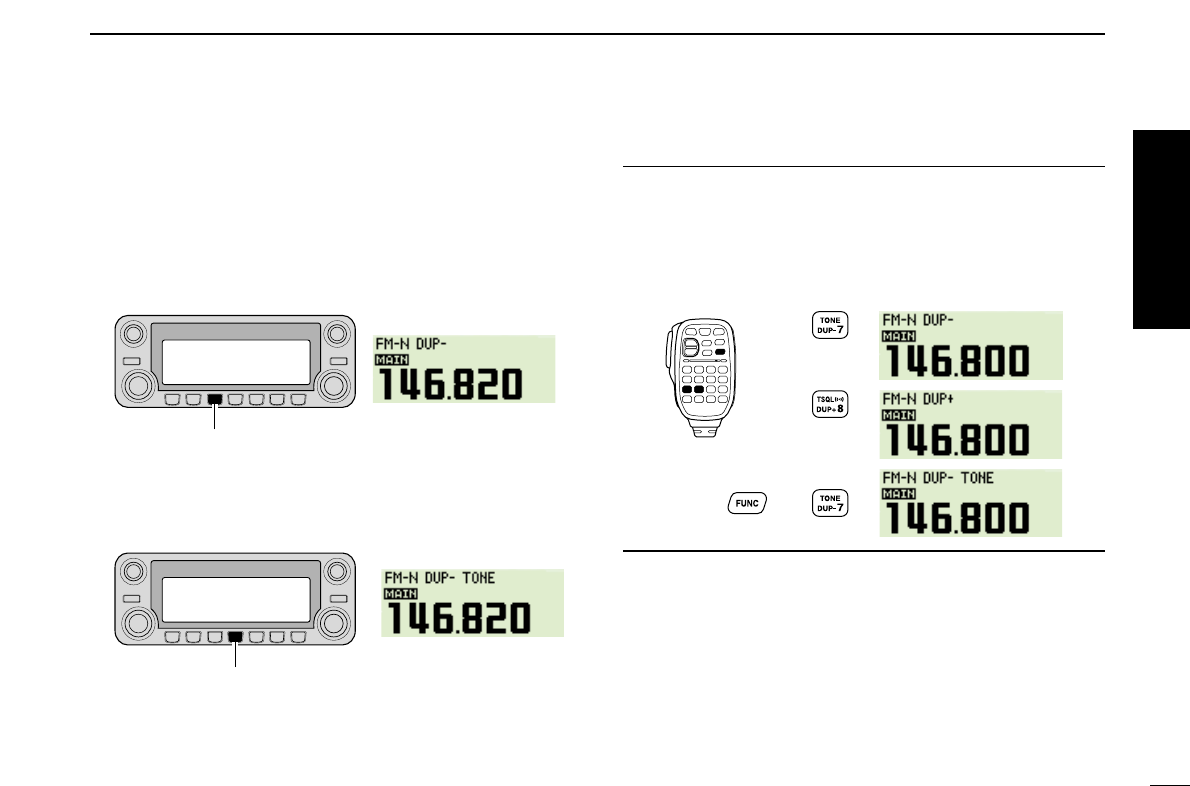
■Repeater operation
1. Setting duplex
Push desired band’s [MAIN•BAND] to select the main band.
Push [DUP•MONI] once or twice to select minus duplex or
plus duplex.
•The USA version has an auto repeater function, therefore, setting
duplex is not required.
2. Repeater tone
Push [TONE•DTMF] several times until “TONE” appears, if
the repeater requires a subaudible tone to be accessed.
Using the HM-133
Plus or minus duplex selection and the repeater tone setting
can be made easily via HM-133.
Push [
DUP
–7(TONE)] for minus duplex; [
DUP
+8(TSQLS)]
for plus duplex selection, push [FUNC] then [
DUP
–7(TONE)]
to turn the repeater tone ON.
Push
Push , then
Push
Push [TONE•DTMF].
Push [DUP•MONI].
Quick reference guide
XI
QUICK REFERENCE GUIDE
■Programming memory channels
The IC-2820H has a total of 522 memory channels (including
20 scan edges and 2 call channels) for storing often used operat-
ing frequency, repeater settings, etc.
Any memory channel can be recalled from either left or right
band.
1. Setting a frequency
In VFO mode, set the desired operating frequency with re-
peater, tone and tuning steps, etc.
➥Push the desired band’s [V/MHz•SCAN] to select VFO.
➥
Rotate the same band’s [DIAL] to set the desired fre-
quency.
•Set other data, such as repeater tone, duplex information, tuning
step), if desired.
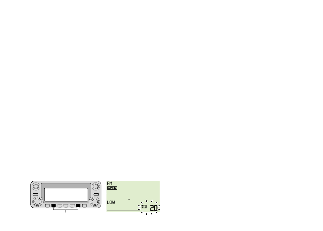
2. Selecting a memory channel
Push and hold the same band’s [M/CALL•MW] for 1 sec.,
then rotate the same band’s [DIAL] to select the desired
memory channel.
•“X” indicator and memory channel number blink.
3. Writing a memory channel
Push and hold the same band’s [M/CALL•MW] for 1 sec. to
program.
•3 beeps sound
•Return to VFO mode automatically after the program.
•Memory channel number automatically increases when continuing
to push the [M/CALL•MW] after programming.
Push [M/CALL•MW] for 1 sec.

XII
QUICK REFERENCE GUIDE
Using the HM-133
qPush [MR/CALL] to select memory mode.
wPush [
ENT
C(T-OFF)] first, then enter the desired memory
channel via the keypad.
ePush [VFO/LOCK] to select VFO mode, then set the de-
sired operating frequency, including offset direction, tone
settings, etc.
➥Push [VFO/LOCK] to select VFO.
➥Push [
ENT
C(T-OFF)] first, then enter the desired oper-
ating frequency via the keypad.
•Set other data, such as repeater tone, duplex information, tun-
ing step, if necessary.
rPush [FUNC] then push and hold [
CLR
A(MW)] for 1 sec.
to program.
•3 beeps sound
•Memory channel number automatically increases when continu-
ing to push [
CLR
A(MW)] after programming.
Push ,
then
Quick reference guide
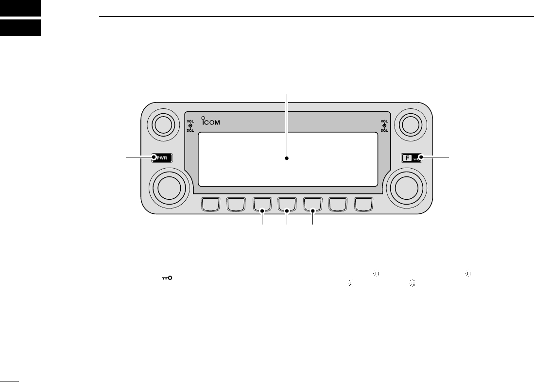
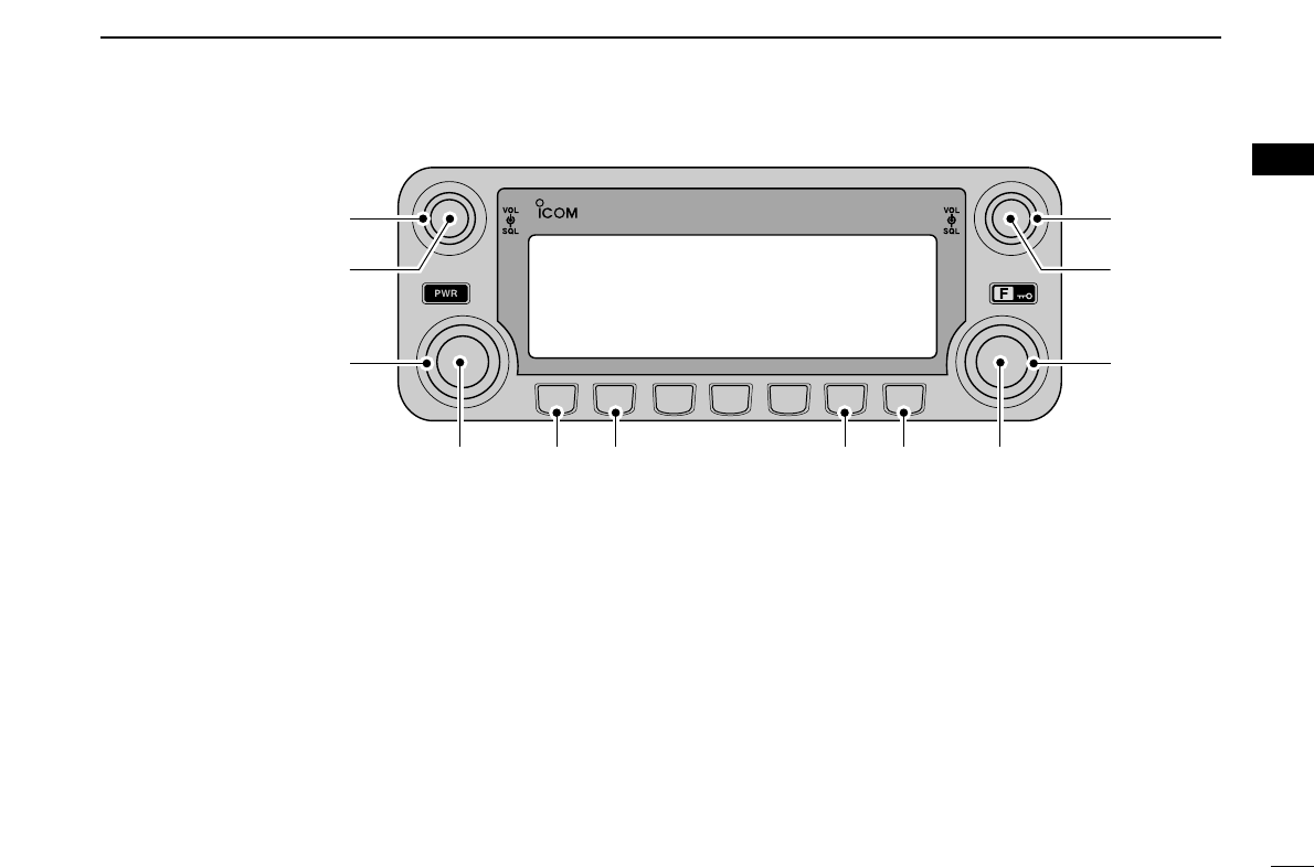
■Front panel— controller
qPOWER KEY [PWR]
Push and hold for 1 sec. to turn power ON and OFF.
wFUNCTION•LOCK KEY [FF•]
➥Push to display the function guide. (p. ??)
➥Push and hold for 1 sec. to turn the lock function ON
and OFF. (p. ??)
eOUTPUT POWER•PRIORITY KEY [LOW•PRIO]
➥Each push changes the output power selection. (p. ??)
➥Push and hold for 1 sec. to start a priority watch. (p. ??)
rTONE•DTMF KEY [TONE•DTMF]
➥Each push selects a tone function. (pgs. ??, ??)
•TONE, TSQL , TSQL, TSQL-R, DTCS , DTCS, DTCS-R,
DSQL , DSQL, CSQL , CSQL or tone function OFF can
be selected.
➥Push and hold for 1 sec. to enter DTMF set mode.
(p. ??)
tDUPLEX•MONITOR KEY [DUP•MONI]
➥Push to select DUP–, DUP+ and simplex (no indications)
operation. (p. ??)
➥Push and hold for 1 sec. to turn the monitor function ON
and OFF. (p. ??)
DUP
MONI
TONE
DTMF
LOW
PRIO
M/CALL
MW
V/MHz
SCAN
V/MHz
SCAN
M/CALL
MW
B
A
N
D
M
A
I
N
B
A
N
D
M
A
I
N
DUAL BAND TRANSCEIVER i2820H
Function display (pgs. 3, 4)
q
ert
w
1
PANEL DESCRIPTION
1
*The keys wto tare for
the MAIN band only.
2
1
PANEL DESCRIPTION
1
2
3
4
5
6
7
8
9
10
11
12
13
14
15
16
17
18
19
ySQUELCH CONTROL [SQL]
Varies the squelch level for left and right band. (p. ??)
•The RF attenuator activates and increases the attenuation when
rotated clockwise to the center position and further. (p. ??)
uVOLUME CONTROL [VOL] (p. ??)
Adjusts the audio level for left or right band.
iTUNING DIAL [DIAL]
Selects the operating frequency (p. ??), memory channel
(p. ??), the setting of the set mode item and the scanning
direction (p. ??) for left or right band.
oMAIN•BAND KEY [MAIN•BAND]
➥Push to select the main band. (p. ??)
➥Push and hold for 1 sec. to enter band selectiion mode.
(p. ??)
!0VFO/MHz TUNING•SCAN KEY [V/MHz•SCAN]
➥Push to select from VFO mode and 1 MHz (or 10 MHz
for some versions) tuning. (p. ??)
➥Push and hold for 1 sec. to enter scan type selection
mode. (p. ??)
•Cancels a scan when pushed during scan.
!1
MEMORY/CALL•MEMORY WRITE KEY [M/CALL•MW]
➥Push to select and toggle memory, call and weather
channel* modes. (pgs. ??, ??, ??, ??)
*Weather channels available for USA versions only.
➥Push and hold for 1 sec. to enter select memory write
mode for memory channel programming. (pgs. ??, ??,
??)
DUP
MONI
TONE
DTMF
LOW
PRIO
M/CALL
MW
V/MHz
SCAN
V/MHz
SCAN
M/CALL
MW
B
A
N
D
M
A
I
N
B
A
N
D
M
A
I
N
DUAL BAND TRANSCEIVER i2820H
Left band Right band
y
u
i
y
u
i
oo!0 !0!1 !1
*The same controls for both the left and
right bands are arranged in symmetry.
3
1PANEL DESCRIPTION
■Function display
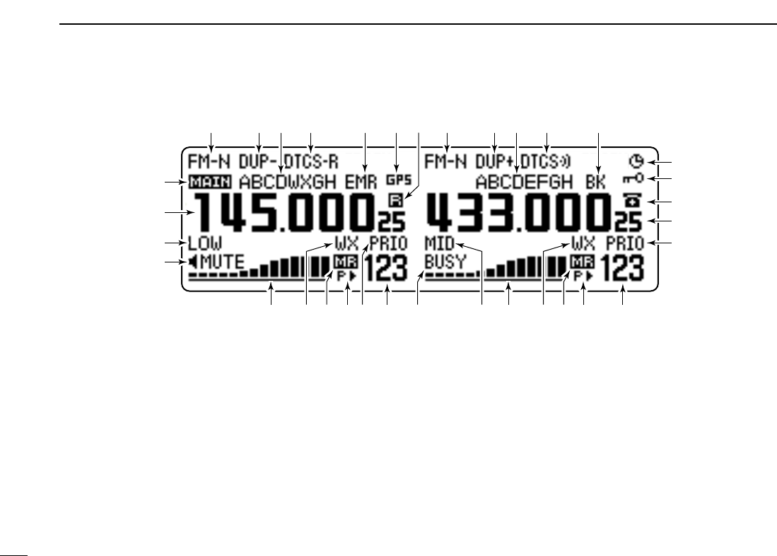
qOPERATING MODE INDICATOR (p. ??)
Shows the selected operating mode.
•FM, FM-N, AM, AM-N and DV* are available, depending on op-
erating band.
*Available only when the optional UT-123 is installed.
wDUPLEX INDICATORS (p. ??)
“DUP+” appears when plus duplex, “DUP –” appears when
minus duplex (repeater) operation is selected.
eNAME INDICATOR
During memory mode operation, the programmed memory
or memory bank name is displayed.
rTONE INDICATOR
➥During FM mode operation:
●
●
“TONE” appears while the repeater tone is in use.
(p. ??)
●
●
“TSQL” appears while the tone squelch function is in
use. (p. ??)
●
●
“TSQL-R” appears while the reverse tone squelch
function is in use. (p. ??)
●
●
“DTCS” appears while the DTCS squelch function is
in use. (p. ??)
●
●
“DTCS-R” appears while the reverse DTCS squelch
function is in use. (p. ??)
qi
@2
!9
!2
@1
!5!5 !4!4 !8!8 !6!7!6!7 @0!3 !9
o
!0
!1
!2
!3
y
t
qwr
er
e
qw
u
*The same indications for both the left and right bands are arranged.

4
1
PANEL DESCRIPTION
1
2
3
4
5
6
7
8
9
10
11
12
13
14
15
16
17
18
19
➥During DV* (Digital) mode operation:
●
●
“DSQL” appears while the digital call sign squelch
function is in use. (p. ??)
●
●
“CSQL” appears while the digital code squelch func-
tion is in use. (p. ??)
➥“” appears with the “TSQL,” “DTCS,” “DSQL”* or “C
SQL”* indicator while the pocket beep function is in use.
(pgs. ??, ??)
*Available only when the optional UT-123 is installed.
tEMR MODE INDICATOR
Appears when the EMR mode* operation is in use.
*Available only when the optional UT-123 is installed.
yGPS INDICATOR
Appears while GPS function* is in use. (p. ??)
*Available only when the optional UT-123 is installed.
uSUB BAND REMOTE CONTROL INDICATOR (p. ??)
Appears when the sub band remote control function is in
use.
iBREAK-IN INDICATOR
Appears when the break-in* operation is in use.
*Available only when the optional UT-123 is installed.
oAUTO POWER OFF INDICATOR
Appears when the auto power OFF function is in use.
!0KEY LOCK INDICATOR
Appears when the key lock function is activated. (p. ??)
!1DTMF INDICATOR
Appears while DTMF memory function is in use.(p. ??)
!2FREQUENCY READOUT
Shows the operating frequency, set mode contents, etc.
•Frequency decimal point blinks while scanning. (p. ??)
!3PRIORITY INDICATOR
Appears while priority watch is activated, blinks while pri-
ority watch is paused. (p. ??)
!4MEMORY CHANNEL NUMBER INDICATORS
➥Shows the selected memory channel number. (p. ??)
➥Shows the selected bank initial. (p. ??)
➥“C” appears when the call channel is selected. (p. ??)
!5SKIP INDICATOR (p. ??)
➥“≈” appears when the displayed memory channel is
specified as a skip channel.
➥“P≈” appears when the displayed frequency is specified
as a program skip frequency.
!6MEMORY INDICATOR (pgs. ??, ??)
Appears when memory mode is selected.
!7WEATHER CHANNEL INDICATOR (p. ??)
“WX” appears when the weather channel is selected.
*Available with the USA version only.
!8S/RF INDICATORS
➥Shows the relative signal strength while receiving sig-
nals. (p. ??)
➥Shows the output power level while transmitting. (p. ??)

5
1PANEL DESCRIPTION
■Function display— continued
!9OUTPUT POWER INDICATORS
“LOW” appears when low output power; “MID” appears
when middle output power, “HI” appears when high output
power is selected.
@0BUSY INDICATOR
➥Appears when a signal is being received or the squelch
is open. (p. ??)
➥Blinks while the monitor function is activated. (p. ??)
@1AUDIO MUTE INDICATOR
Appears when the audio mute (p. ??)or sub band mute
(p. ??)function is in use.
@2MAIN INDICATOR (p. ??)
Indicates the main band for transmit and function control.
qi
@2
!9
!2
@1
!5!5 !4!4 !8!8 !6!7!6!7 @0!3 !9
o
!0
!1
!2
!3
y
t
qwr
er
e
qw
u
*The same indications for both the left and right bands are arranged.
6
1
PANEL DESCRIPTION
1
2
3
4
5
6
7
8
9
10
11
12
13
14
15
16
17
18
19
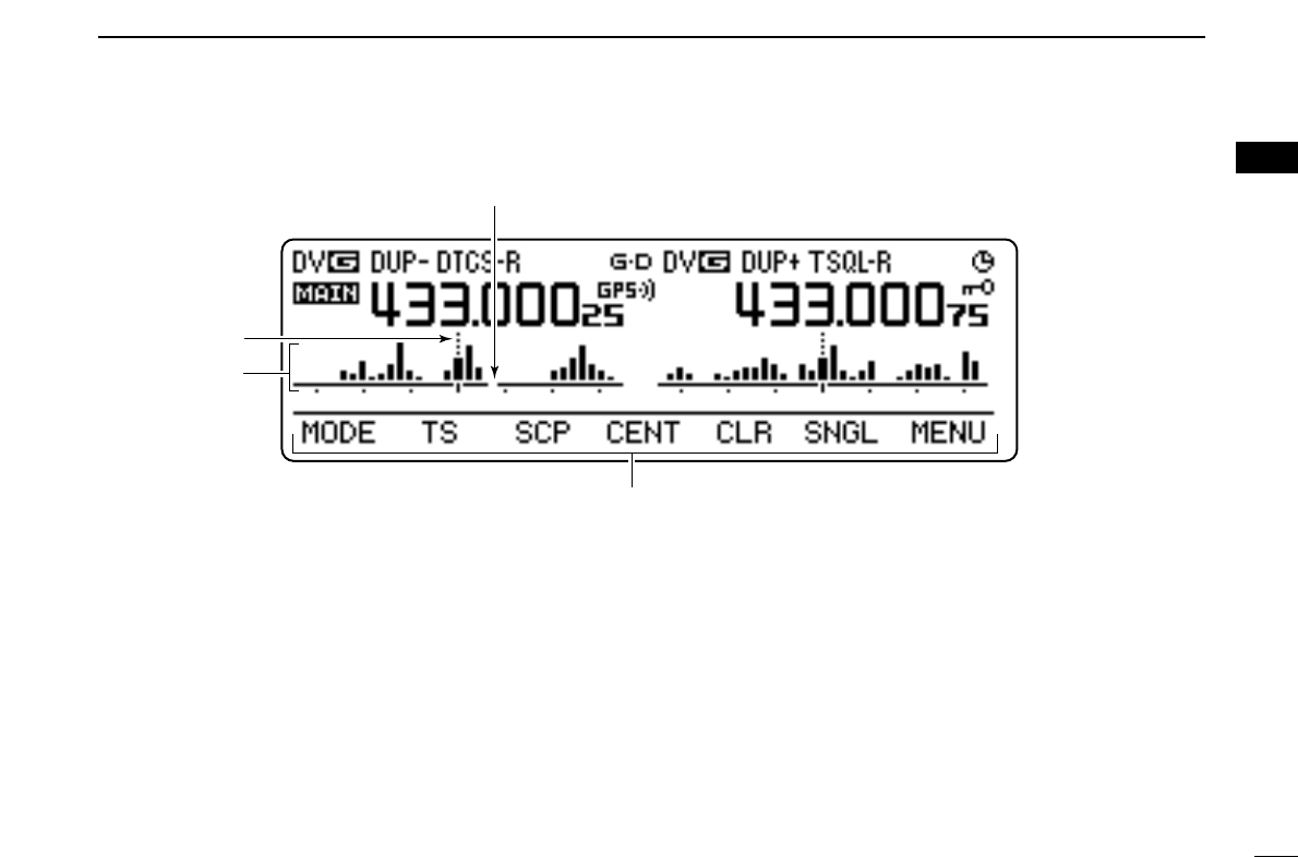
@3FREQUENCY MARKER (p. ??)
Shows the selected frequency in the band scope.
@4CENTER FREQUENCY MARKER
Shows the center frequency of the band scope.
@5BAND SCOPE INDICATOR
When the band scope function is in use, shows the band
conditions.
@3
@4
@5
Function guide indications (pgs. ??–??)
7
1PANEL DESCRIPTION
■Function guide indications
The function guide indications allow you to simplifying a wide
variety of function operation
DFunction guide
qMODE KEY [MODE](V/MHz•SCAN) (p. ??)
Push to select an operating mode from FM, FM-N, AM,
AM-N and DV* in main band.
*Available only when the optional UT-123 is installed.
wTUNING STEP KEY [TS](M/CALL•MW) (p. ??)
Push to display the tuning step selection mode.
•5.0,* 6.25,* 10, 12.5, 15,* 20, 25, 30 and 50 kHz steps are avail-
able. *Not selectable in 900 MHz band.
eBAND SCOPE KEY [SCP](DUP•MONI) (p. ??)
➥Push to display the simple band scope and sweeps 1
time.
➥Push and hold for 1 sec. to display the simple band
scope and sweeps continuously.
•Push [SCP](DUP•MONI) momentarily to cancel the sweep.
rSCAN SKIP KEY [SKIP](TONE•DTMF) (p. ??)
During in memory mode, push to select the scan skip con-
dition for the selected memory channel.
•“≈” appears when memory skip, “P≈” appears when program
skip selection.
tMEMORY NAME INDICATION KEY [M.N](LOW•PRIO)
(p. ??)
Push select the memory name indication condition.
•Memory name, frequency and OFF selections are available.
ySINGLE WATCH KEY [SNGL](M/CALL•MW) (p. ??)
Push select the single watch mode.
•Push [DUAL](M/CALL•MW)(for right band) to select the dual
watch mode.
uMENU MODE KEY [MENU](V/MHz•SCAN) (p. ??)
Push select the menu mode indication.
DFunction guide 2
The function guide 2 indications appear only when the op-
tional UT-123 is installed and DV mode is selected.
iCALL SIGN SELECT KEY [CS](V/MHz•SCAN) (p. ??)
Push to display the call sign selection screen.
oRECEIVED CALL SIGN RECORD KEY
[CD](M/CALL•MW) (p. ??)
Push to display the received call sign record screen.
!0CQ KEY [CQ](DUP•MONI) (p. ??)
Push to set “CQCQCQ” as the station call sign for the call.
io!0!1!2!3u
qwertyu
8
1
PANEL DESCRIPTION
1
2
3
4
5
6
7
8
9
10
11
12
13
14
15
16
17
18
19
!1CALL SIGN SET KEY [R>CS](TONE•DTMF) (p. ??)
Push to copy and set the previously received station call
sign as the station call sign for the call.
!2DV MESSAGE KEY [MSG](LOW•PRIO) (p. ??)
Push to display the DV message screen.
!3VOICE MEMORY KEY [REC](V/MHz•SCAN) (p. ??)
Push to display the DV voice memory record screen.
DFunction guide 3*
The function guide 3 indications appear only when the op-
tional UT-123 is installed.
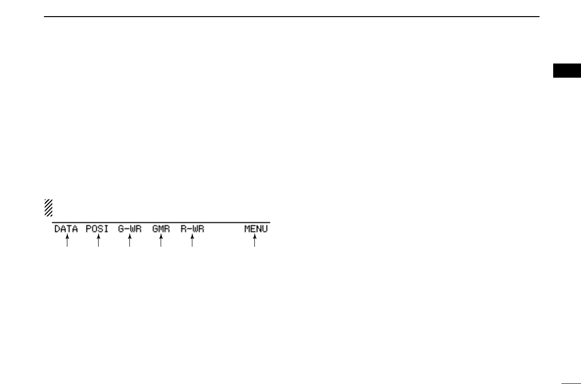
!4DATA KEY [DATA](V/MHz•SCAN) (p. ??)
Push to toggle the GPS data communication ON and OFF.
•“G•D” appears when the GPS data communication is set to ON.
!5POSITION INFORMATION KEY [POSI](M/CALL•MW)
(p. ??)
Push to display the position information screen.
!6GPS DATA STORE KEY [G-WR](DUP•MONI) (p. ??)
Push and hold for 1 sec. to store the received position in-
formation.
!7GPS MEMORY RECALL KEY [GMR](TONE•DTMF)
(p. ??)
Push to select the GPS memory screen to display the
stored positon information.
!8DV MESSAGE KEY [MSG](LOW•PRIO) (p. ??)
Push to display the DV message screen.
!4 !5 !6 !7 !8 u
9
1PANEL DESCRIPTION
■Main unit
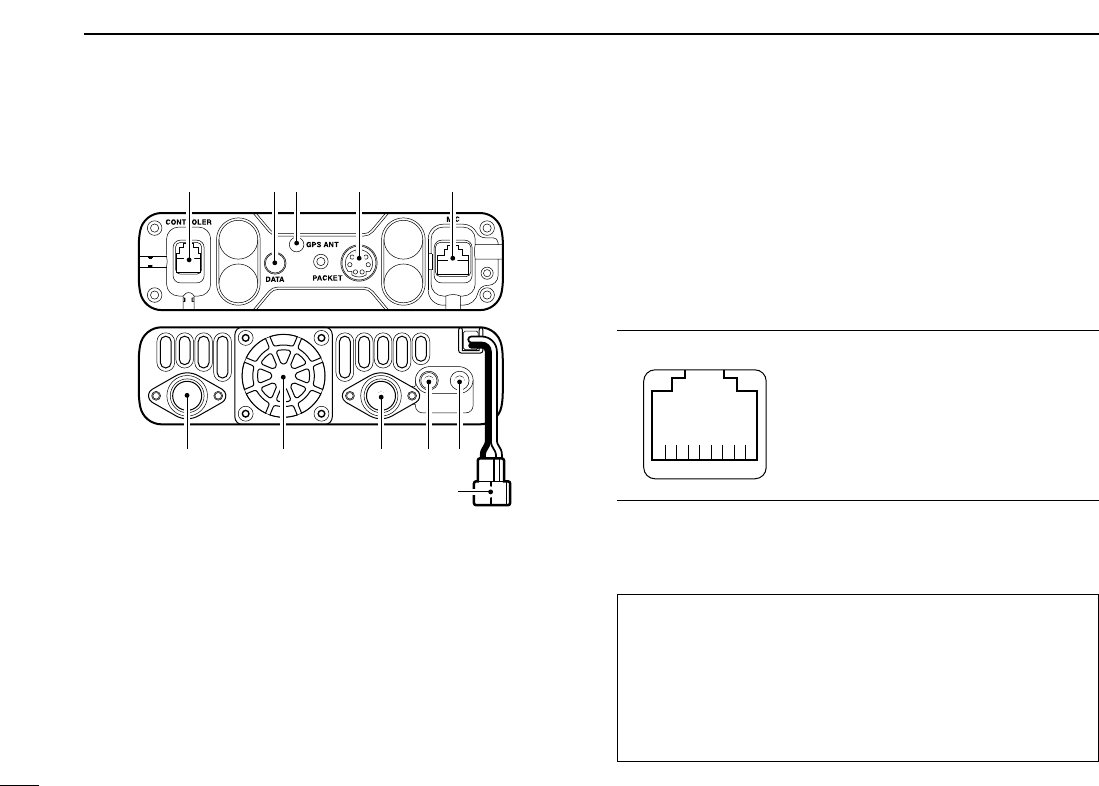
qCONTROLLER CONNECTOR [CONTROLLER] (p. V)
Connects the controller unit with the supplied cable.
wDATA JACK [DATA]
Connect to a PC via optional data communication cable
OPC-1529 for slow-speed data communication in DV* mode
operation.
*Available only when the optional UT-123 is installed.
eGPS ANTENNA SOCKET [GPS ANT] (p. V)
Connects the GPS antenna supplied with the optional UT-
123.
rPACKET JACKS [PACKET] (p. V)
Connect a TNC (Terminal Node Controller), etc. for data com-
munications. The receiver can support 9600 bps packet
communication (AFSK).
tMICROPHONE CONNECTOR [MIC]
Connects the supplied or an optional microphone.
q+8 V DC output (Max. 10 mA)
wChannel up/down
e8 V control IN
rPTT
tGND (microphone ground)
yMIC (microphone input)
uGND
iData IN
yANTENNA CONNECTOR [ANT1]
Connects a 50 Ωantenna with a PL-259 connector and a
50 Ωcoaxial cable for transmission and reception.
ANTENNA INFORMATION
For radio communications, the antenna is of critical impor-
tance, to maximize your output power and receiver sensi-
tivity. The transceiver accepts a 50 Ωantenna and less
than 1:1.5 of Voltage Standing Wave Ratio (VSWR). High
SWR values not only may damage the transceiver but also
lead to TVI or BCI problems.
q
i
qwr te
!1
uio!0y
10
1
PANEL DESCRIPTION
1
2
3
4
5
6
7
8
9
10
11
12
13
14
15
16
17
18
19
uCOOLING FAN
Rotates while transmitting.
Also rotates while receiving depending on the setting in
set mode. (p. ??)
iANTENNA CONNECTOR [ANT2]
Connects a 50 Ωantenna with a PL-259 connector and a
50 Ωcoaxial cable for diversity reception.
oEXTERNAL SPEAKER JACK 1 [SP-1]
Connects an 8 Ωspeaker. Outputs both left and right
bands audio when no external speaker is connected to
[SP-2]. See the table below for details.
•Audio output power is more than 2.4 W.
!0EXTERNAL SPEAKER JACK 2 [SP-2]
Connects an 8 Ωspeaker. Outputs right band’s audio only.
•Audio output power is more than 2.4 W.
!1POWER RECEPTACLE [DC13.8V]
Accepts 13.8 V DC ±15% with the supplied DC power
cable.
☞NOTE: DO NOT use a cigarette lighter socket as a
power source when operating in a vehicle. The plug
may cause voltage drops and ignition noise may be su-
perimposed onto transmit or receive audio.
• Speaker information
Connected Left band audio Right band audio
speaker
No external Internal speaker (mixed audio)
speakers
[SP-1] only External speaker (mixed audio)
[SP-2] only Internal speaker External speaker
2 external External speaker via External speaker via
speakers [SP-1] [SP-2]
11
1PANEL DESCRIPTION
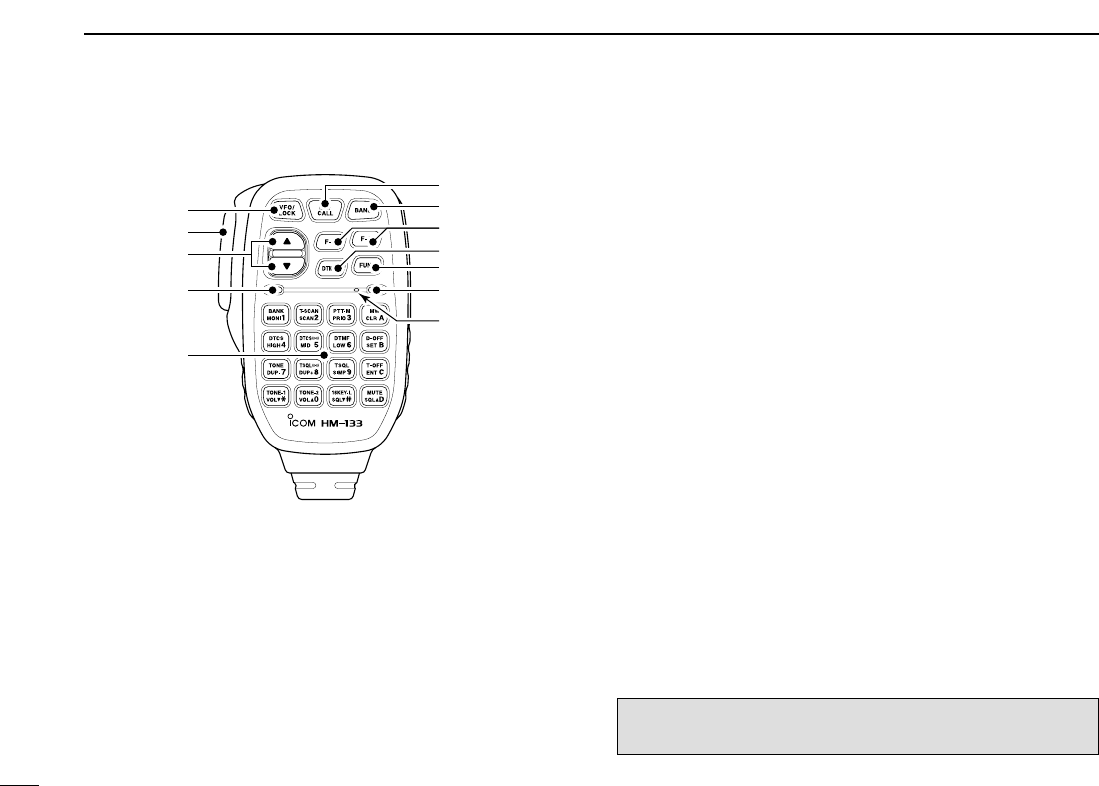
■Microphone (HM-133*)
qVFO/LOCK KEY [VFO/LOCK]
➥Push to select VFO mode. (p. 12)
➥Push and hold for 1 sec. to turn the lock function ON
and OFF. (p. 15)
wPTT SWITCH
➥Push and hold to transmit; release to receive.
➥Switches between transmitting and receiving while the
one-touch PTT function is in use. (p. 21)
eUP/DOWN KEYS [Y]/[Z]
➥Push either key to change operating frequency, mem-
ory channel, set mode setting, etc.
(pgs. 13, 29, 56)
➥Push and hold either key for 1 sec. to start scanning.
(p. 41)
rACTIVITY INDICATOR
➥Lights red while any key, except [FUNC] and [DTMF-S],
is pushed, or while transmitting.
➥Lights green while the one-touch PTT function is in use.
tKEYPAD (pgs. 8, 9)
yFUNCTION INDICATOR
➥Lights orange while [FUNC] is activated—indicates the
secondary function of keys can be accessed.
➥Lights green when [DTMF-S] is activated—DTMF sig-
nals can be transmitted with the keypad.
u2nd FUNCTION KEY [FUNC]
iDTMF SELECT KEY [DTMF-S] (p. 50)
oFUNCTION KEYS [F-1]/[F-2] (p. 66)
Program and recall your desired transceiver conditions.
!0BAND KEY [BAND] (p. 11)
Push to select main band between left and right bands.
!1MEMORY/CALL KEY [MR/CALL]
➥Push to select memory mode. (p. 12)
➥Push and hold for 1 sec. to select call channel. (p. 38)
✔
Important!
All keys on the microphone function for the main band only.
Mic element
q
e
r
t
w
y
u
i
o
!0
!1
■Microphone keypad
12
1
PANEL DESCRIPTION
1
2
3
4
5
6
7
8
9
10
11
12
13
14
15
16
17
18
19
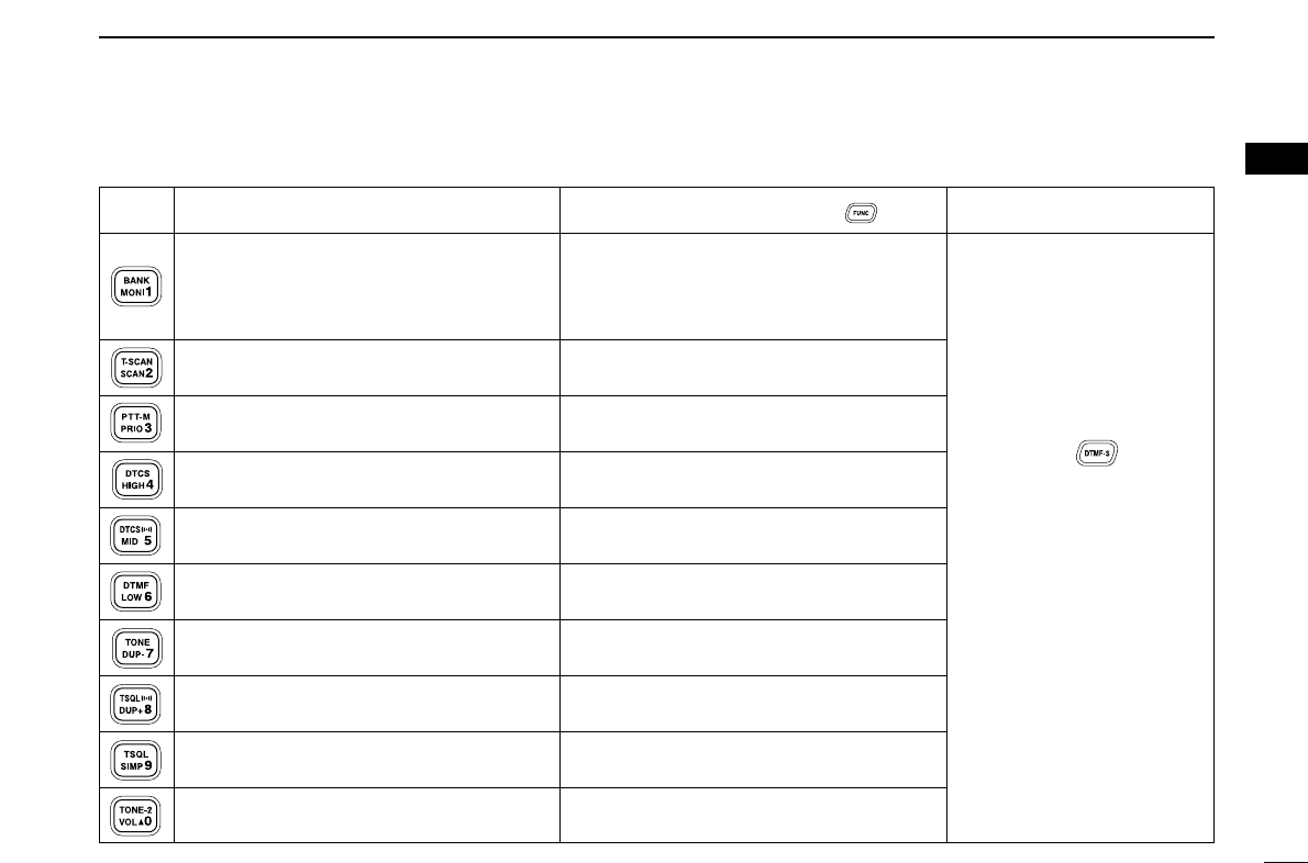
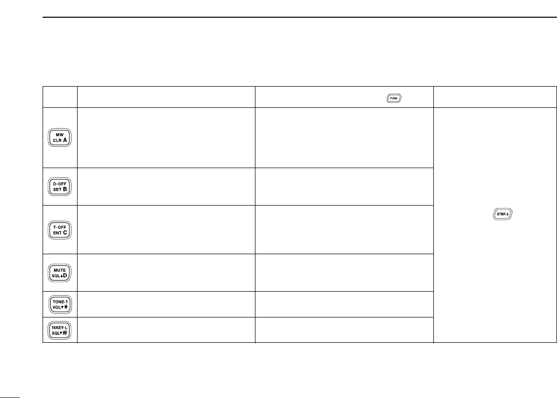
KEY FUNCTION SECONDARY FUNCTION ( +key) OTHER FUNCTIONS
Switches between opening and closing the
squelch. (p. 16)
Starts and stops scanning. (p. 41)
Starts and stops priority watch. (p. 47)
Selects high output power. (p. 20)
Selects mid. output power. (p. 20)
Selects low output power (p. 20)
Selects minus duplex operation. (p. 24)
Selects plus duplex operation. (p. 24)
Selects simplex operation. (p. 24)
Increases audio output level. (p. 16)
In VFO mode enters operating band select-
ing condition. (p. 12)
In memory mode enters bank selecting
condition. (p. 35)
Starts and stops tone scanning. (p. 55)
Turns the one-touch PTT function ON and
OFF. (p. 21)
Turns the DTCS squelch ON. (p. 53)
Turns the DTCS pocket beep function ON.
(p. 53)
Turns the DTMF memory encoder function
ON. (p. 49)
Turns the subaudible tone encoder ON.
(p. 24)
Turns the CTCSS pocket beep function
ON. (p. 53)
Turns the tone squelch function ON.
(p. 53)
Sends a 1750 Hz tone signal while pushing
and holding. (p. 26)
After pushing :
Transmits the appropriate
DTMF code. (pgs. 26, 50)
When the DTMF memory en-
coder is activated, push [0] to
[9] to transmit the appropriate
DTMF memory contents .
(p. 50)
13
1PANEL DESCRIPTION
➥Cancels frequency entry. (p. 13)
➥Cancels the scan or priority watch.
(pgs. 41, 47)
➥Exit set mode. (p. 56)
➥Enters set mode (p. 56)
➥Advances the set mode selection order
after entering set mode. (p. 56)
➥Sets the keypad for numeral input.
(p. 13)
➥Reverses the set mode selection order
after entering set mode. (p. 56)
Adjusts the squelch level increments.
(p. 16)
Decreases audio output level. (p. 16)
Adjusts the squelch level decrement.
(p. 16)
➥Selects a memory channel for program-
ming. (p. 31)
➥Advances the memory channel number
when continuously pushed after pro-
gramming is completed. (p. 31)
DTMF memory encoder function OFF.
(p. 50)
Turns the subaudible tone encoder, pocket
beep or CTCSS/DTCS tone squelch OFF.
(pgs. 24, 53)
Mutes the audio. (p. 21)
•Mute function is released when any oper-
ation is performed.
Sends a 1750 Hz tone signal for 0.5 sec.
(p. 26)
Locks the digit keys on the keypad (includ-
ing the A to D, # and Mkeys. (p. 15)
After pushing :
Transmits the appropriate
DTMF code. (pgs. 26, 50)
KEY FUNCTION SECONDARY FUNCTION ( +key) OTHER FUNCTIONS
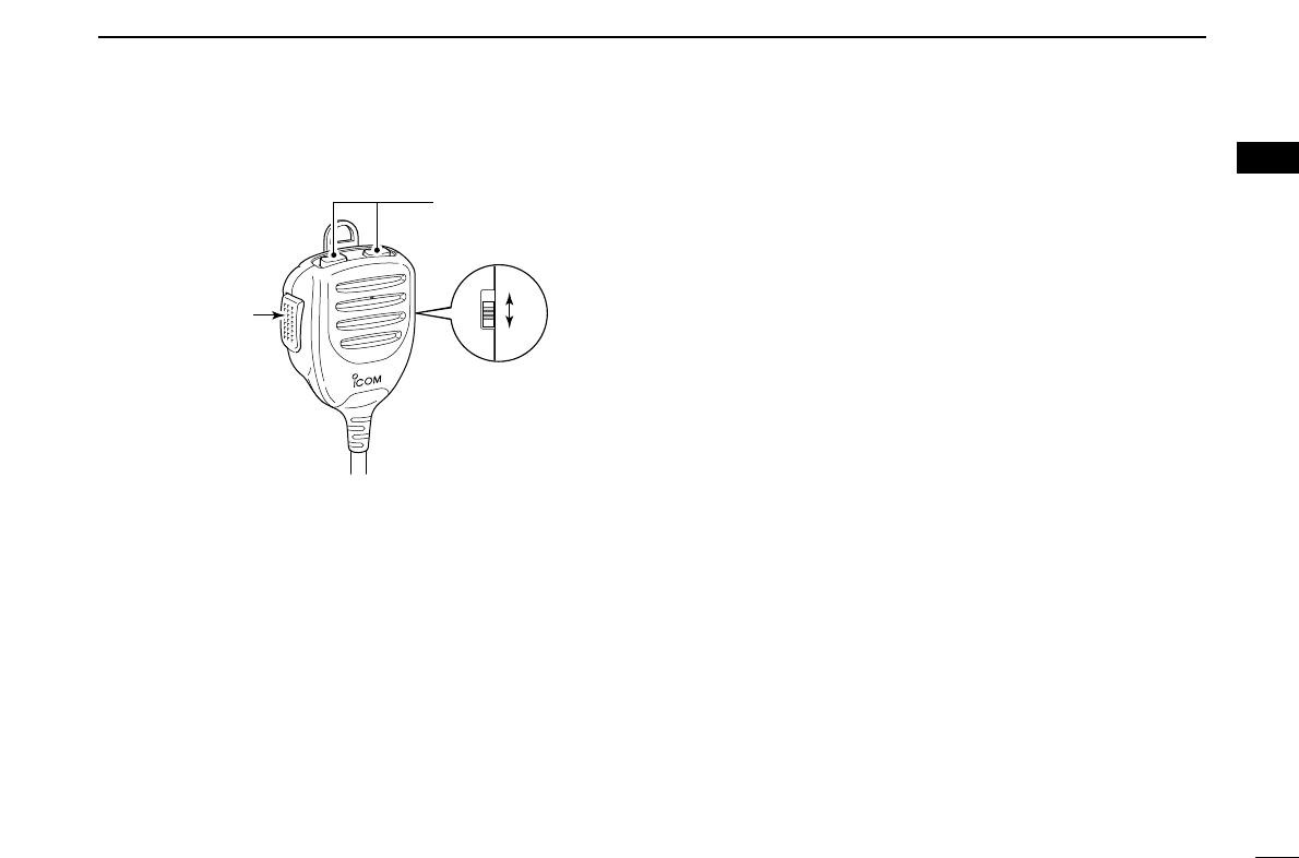
■Optional Microphone (HM-154)
qPTT SWITCH
Push and hold to transmit; release to receive.
wUP/DOWN KEYS [UP]/[DN]
➥Push either key to change operating frequency, mem-
ory channel, set mode setting, etc.
(pgs. 13, 29, 56)
➥Push and hold either key for 1 sec. to start scanning.
(p. 41)
eUP/DN LOCK SWITCH
Slide to toggle [UP]/[DN] keys function ON and OFF.
w
q
ON
OFF
e
14
1
PANEL DESCRIPTION
1
2
3
4
5
6
7
8
9
10
11
12
13
14
15
16
17
18
19
*
A different microphone
may be supplied de-
pending on version.
15
SETTING A FREQUENCY
2
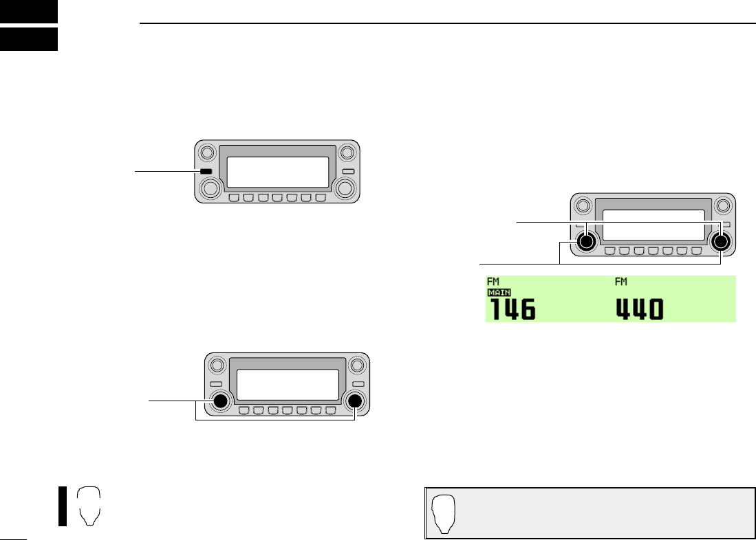
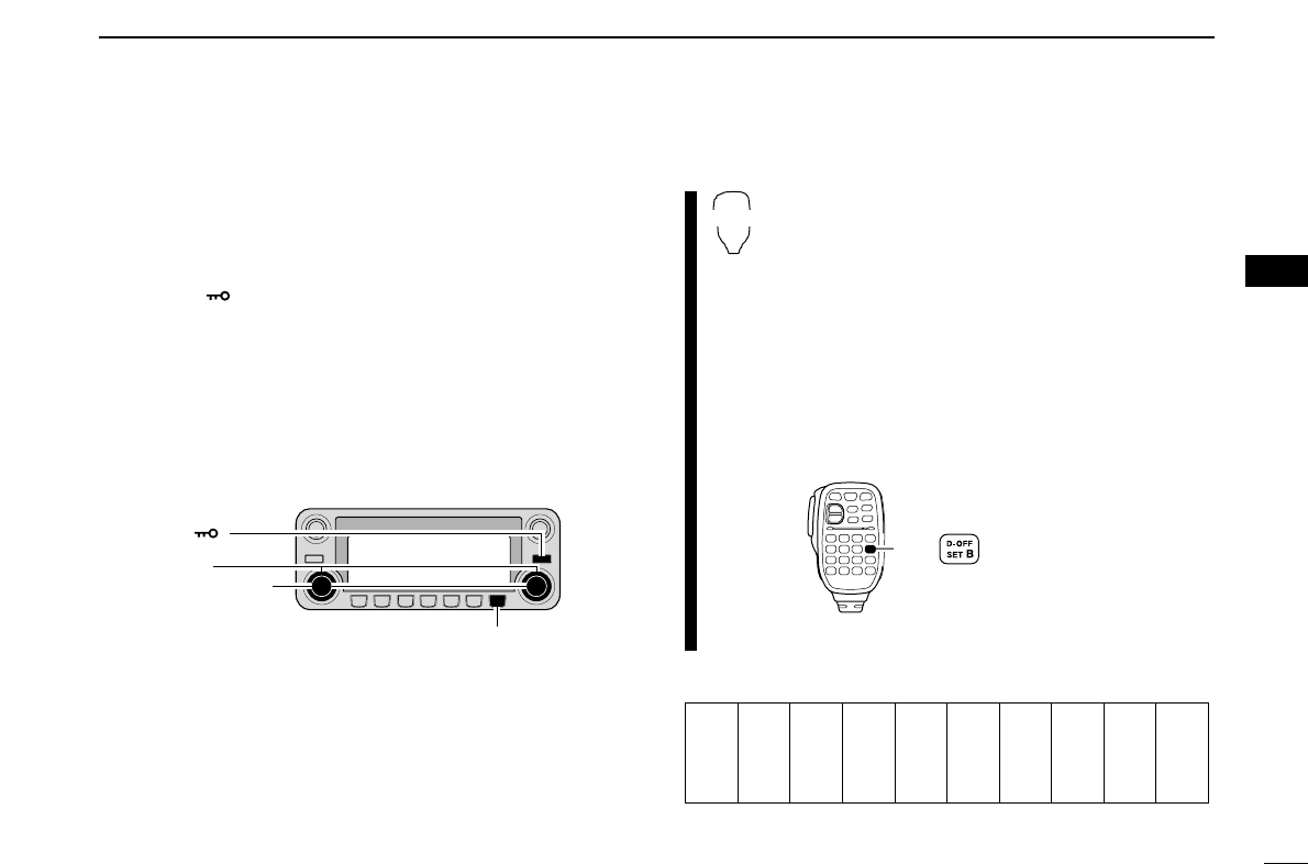
■Preparation
DTurning power ON/OFF
➥Push and hold [PWR] for 1 sec. to turn power ON and
OFF.
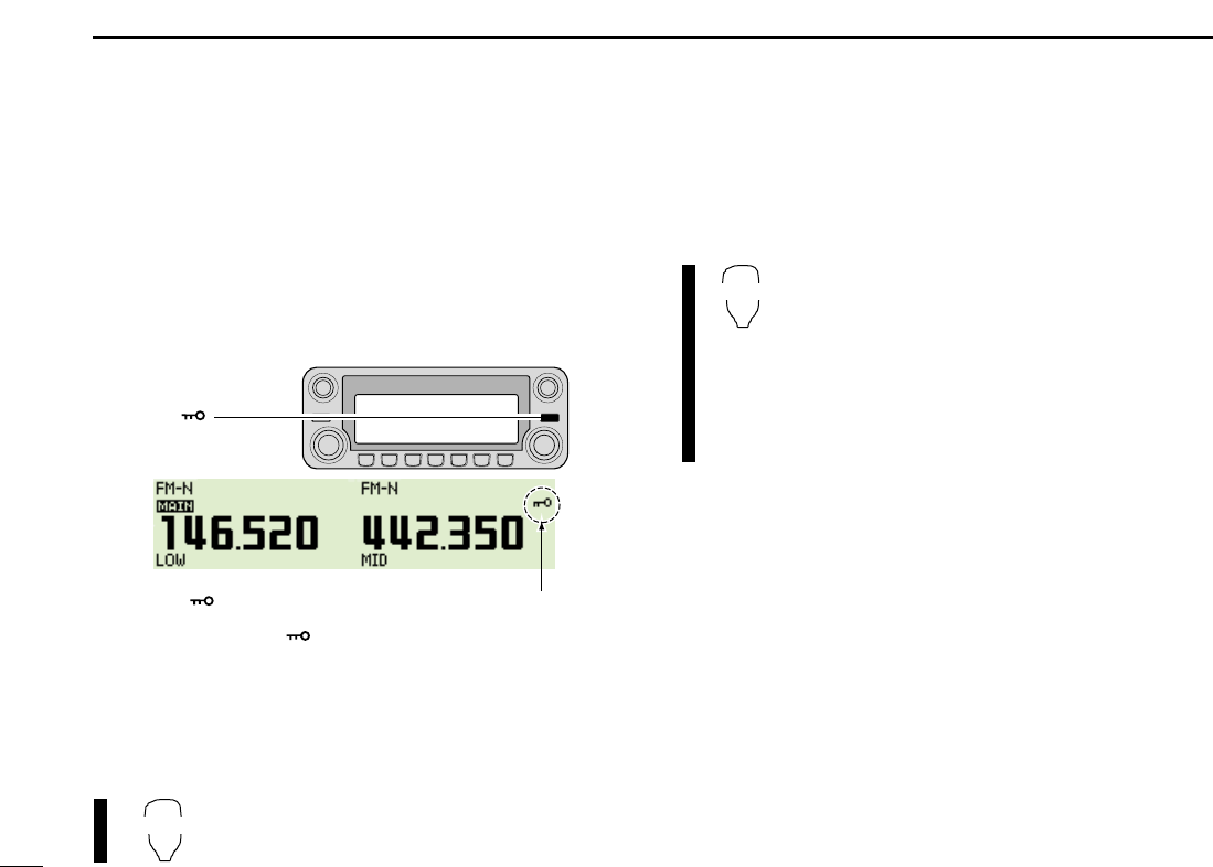
DMAIN band
The IC-2820H can receive 144 MHz and 430(440) MHz band
signals simultaneously. To activate all functions access or to
change frequency via the microphone, you must designate
one band as the main band. The transceiver transmits a sig-
nal on the main band only.
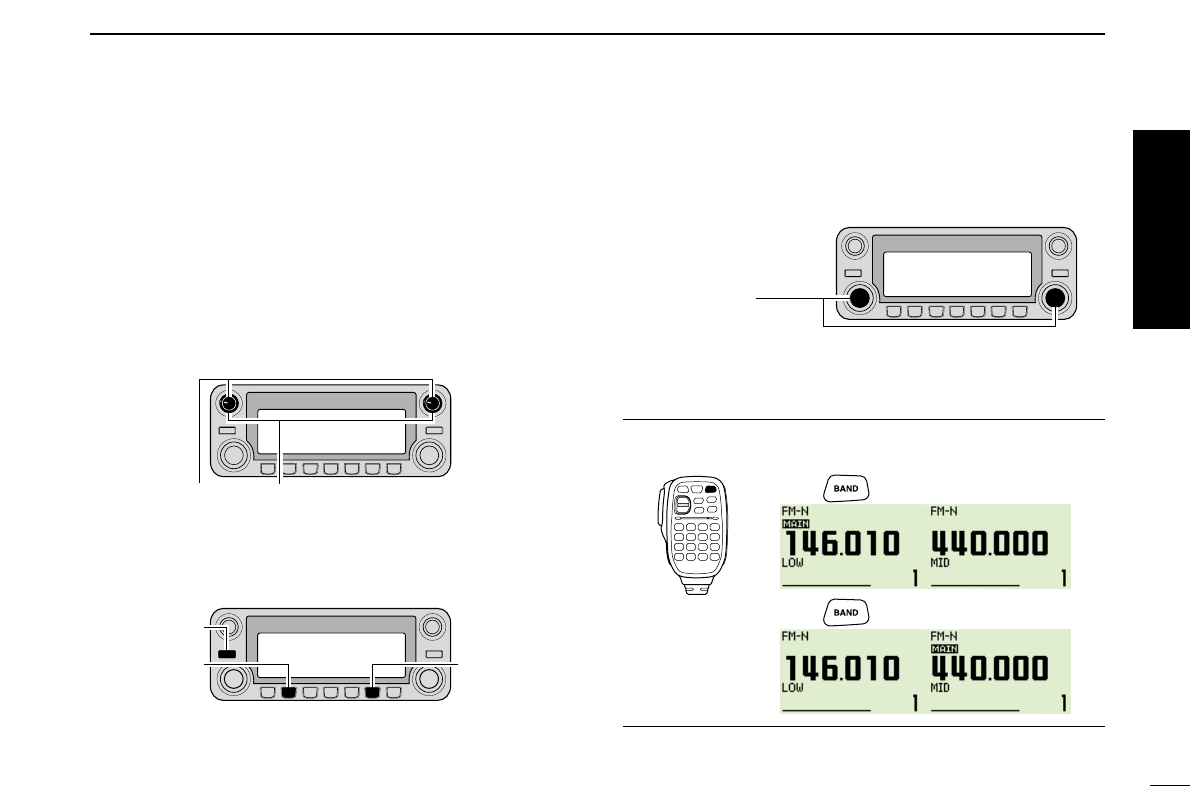
➥Push the desired band’s [MAIN•BAND] to select the main
band.
•“Q” indicates the main band.
➥Push [BAND] to toggle the main band between
left and right bands.
DOperating frequency band selection
In the default condition, or after resetting the CPU, 2 m band
is assigned in the left band, 70 cm band is assigned in the
right band. However, the 2 m band can also be assigned into
the right, and 70 cm band can also be assigned into the left
band.
qPush and hold the desired band’s [MAIN•BAND] for 1 sec.
•Frequency band initial appears.
wRotate the same band’s [DIAL] to select the desired fre-
quency band.
•Pushing [Y]/[Z] on the microphone also selects the band.
ePush the [MAIN•BAND] to return to frequency indication in
the selected frequency band.
[DIAL]
[MAIN•BAND]
Frequency band initial is displayed.
BAND
[MAIN•BAND]
[PWR]
Note that in this manual, sections beginning with a micro-
phone icon (as at left), designate operation via the HM-133
microphone.
16
2
SETTING A FREQUENCY
1
2
3
4
5
6
7
8
9
10
11
12
13
14
15
16
17
18
19
zPush [BAND] to select main band.
xPush and hold [BAND] for 1 sec. to enter fre-
quency band selecting condition.
•The frequency band is displayed.
cPush [Y]/[Z] to select the desired frequency
band.
vPush [
CLR
A(MW)] to exit the condition, and re-
turn to frequency indication.
✔
About extra frequency bands
— USA and General versions only
In addition to the 2 m and 70 cm ham bands, the IC-2820H
USA and General versions have extra frequency bands for
each left and right bands as follow.
See the specifications for the available frequency bands for
details.
*The frequency band initials are default indication only. Once the op-
erating frequency is set in the band, the initial indication will be
changed. ✔: Available, —: Not available
DVFO and memory modes
The transceiver has 2 basic operating modes: VFO mode and
memory mode. Select VFO mode first to set an operating fre-
quency.
➥Push the desired band’s [V/MHz•SCAN] to select VFO
mode.
•When VFO mode is already selected, the digit below 10 MHz
(the digit below 1 MHz or 100 kHz disappear depending on ver-
sions) disappear. In this case, push [V/MHz•SCAN] again (or
twice or 3 times depending on version).
➥Push [M/CALL•MW] to select memory mode.
•“X” indicator appears when memory mode is selected.
➥Push [VFO/LOCK] to select VFO mode.
➥Push [MR/CALL] to select memory mode.
•The microphone controls the main band only. Push
[BAND] to toggle the main band, then push
[VFO/LOCK] or [MR/CALL], if necessary.
VFO/LOCK
[M/CALL•MW]
VFO mode is selected. “X” indicator appears when
memory mode is selected.
[V/MHz•SCAN]
BANK
[Y]/[Z]
Frequency Left band Right band
band initial*
127 ✔✔
136 ✔✔
146 ✔✔
220 ✔—
375 ✔✔
440 ✔✔
500 ✔✔
900 —✔
17
2SETTING A FREQUENCY
■Using the tuning dial
qRotate the desired band’s [DIAL] to set the frequency.
•If VFO mode is not selected, push the same band’s
[V/MHz•SCAN] to select VFO mode.
•The frequency changes in the selected tuning steps. (p. ??)
w
To change the frequency in 1 MHz (10 MHz for some versions)
steps, push [V/MHz•SCAN], then rotate [DIAL].
•Pushing and holding [V/MHz•SCAN] for 1 sec. starts scan func-
tion. If scan starts, push [V/MHz•SCAN] again to cancel it.
■Using the [Y]/[Z] keys
➥Push [Y] or [Z] to select the desired frequency.
•Push [BAND] to select the desired band (left or right)
as the main band in advance.
•Pushing and holding [Y]/[Z] for 1 sec. activates a
scan. If scan starts, push [Y]/[Z] or [
CLR
A(MW)] to
cancel it.
■Using the keypad
The frequency can be directly set via numeral keys on the mi-
crophone.
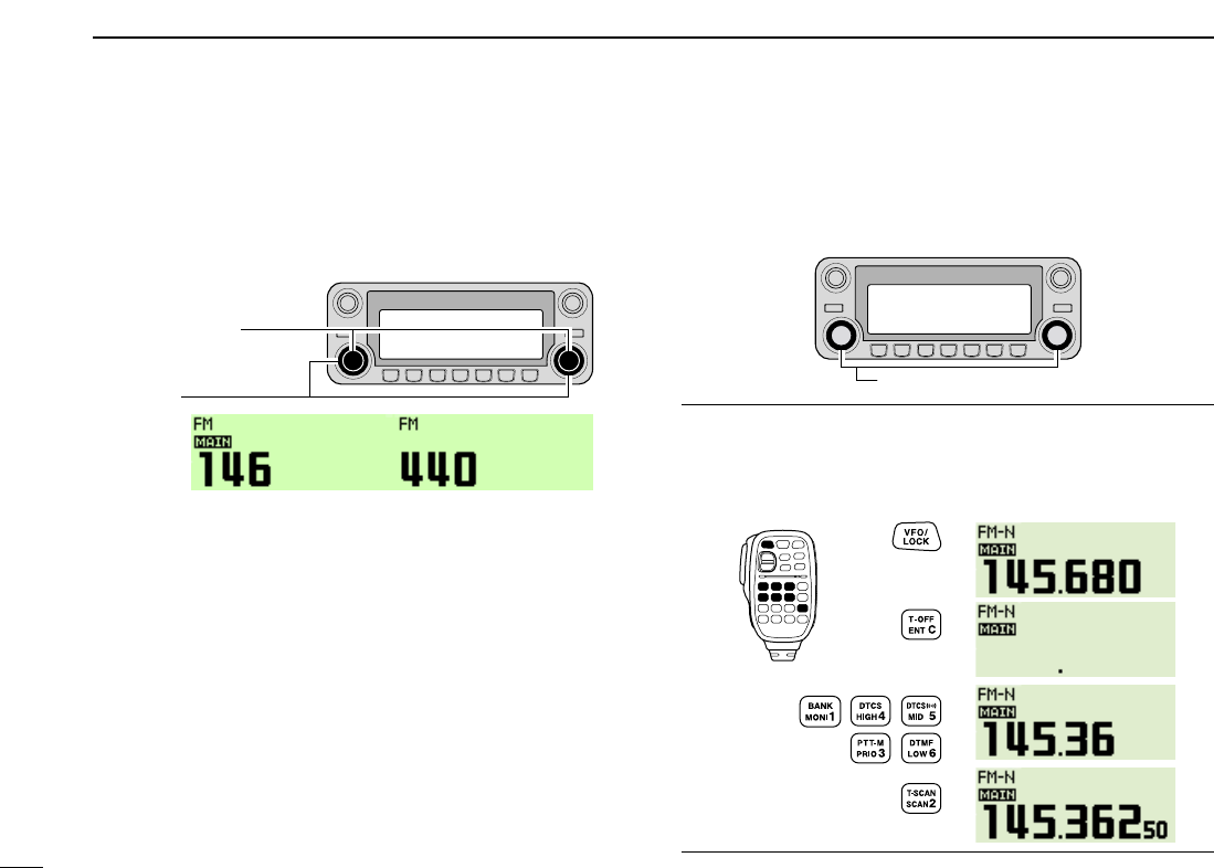
zPush [BAND] to select the desired band (left or
right) as the main band.
•Push [VFO/LOCK] to select VFO mode, if necessary.
xPush [
ENT
C(T-OFF)] to activate the keypad for
digit input.
cPush 6 keys to input a frequency.
•When a digit is mistakenly input, push [
ENT
C(T-OFF)]
to clear the input, then repeat input from the 1st digit.
•Pushing [
CLR
A(MW)] clears input digits and retrieves
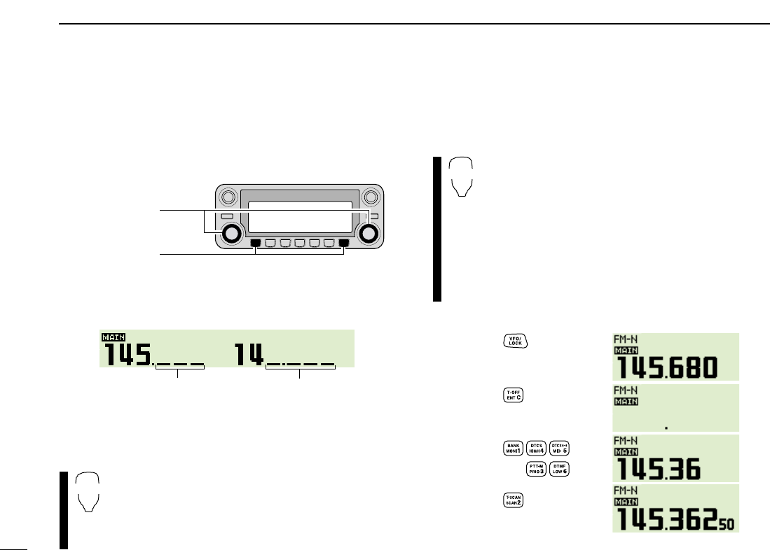
the frequency.
Push
Push
Push
Push
[EXAMPLE]: Setting frequency to 145.3625 MHz.
ENT
C
YZ
While 1 MHz tuning step is selected,
the digit below 100kHz disappear.
While 10 MHz tuning step is selected,
the digit below 1 MHz disappear.
[V/MHz•SCAN]
[DIAL]
18
2
SETTING A FREQUENCY
1
2
3
4
5
6
7
8
9
10
11
12
13
14
15
16
17
18
19
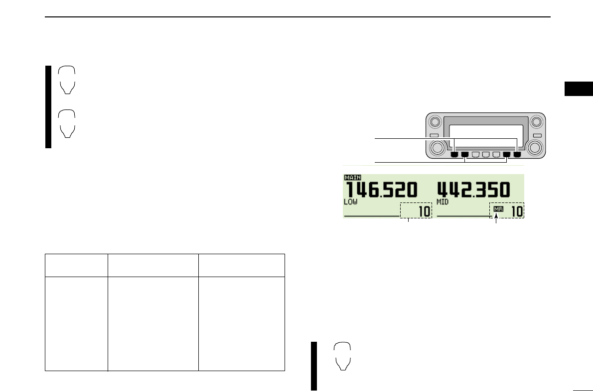
■Tuning step selection
Tuning steps are the minimum frequency change increments
when you rotate [DIAL] or push [Y]/[Z] on the microphone.
Independent tuning step for the left and right, as well as each
frequency bands can be set for individual tuning convenience.
The following tuning steps are available.
•5 kHz* •6.25 kHz* •10 kHz •12.5 kHz
•15 kHz* •20 kHz •25 kHz •30 kHz
•50 kHz
*Not selectable in 900 MHz band.
☞NOTE: For convenience, select a tuning step that matches
the frequency intervals of repeaters in your area.
qPush the desired band’s [MAIN•BAND] to select the main
band.
•Push the same band’s [V/MHz•SCAN] to select VFO mode, if
necessary.
wPush [F•]to display the function guide.
ePush [TS](M/CALL•MW) (Left band’s) to enter tuning step
set mode.
rRotate the same band’s [DIAL] to select the desired tun-
ing step.
tPush [F•]to exit tuning step set mode.
[TS](M/CALL•MW)
[F• ]
19
2SETTING A FREQUENCY
■Lock functions
To prevent accidental frequency changes and unnecessary
function access, use the lock function. The transceiver has 2
different lock functions.
DFrequency lock
This function locks dials and keys electronically and can be
used together with the microphone lock function.
➥Push and hold [F•]for 1 sec. to turn the lock function
ON and OFF.
•[PTT], [DUP•MONI] (monitor function only), [VOL], [SQL] and
[MAIN•BAND] (main band selection only) can be used while the
channel lock function is in use. Also, TONE-1, TONE-2, DTMF
tones or DTMF memory contents can be transmitted from the mi-
crophone.
➥Push and hold [VFO/LOCK] for 1 sec. to
turn the lock function ON and OFF.
DMicrophone keypad lock
This function locks the microphone keypad.
➥Push [FUNC] then [
SQL
ZD(16KEY-L)] to turn
the microphone keypad lock function ON and
OFF.
•[PTT], [VFO/LOCK], [MR/CALL], [BAND], [Y], [Z],
[F-1], [F-2], [DTMF-S] and [FUNC] on the micro-
phone can be used.
•All keys on the transceiver can be used.
•The keypad lock function is released when the
power is turned OFF then ON again.
16KEY-L
VFO/LOCK
[F• ]
“ ” appear while the lock function is activated.
20
3
BASIC OPERATION
1
2
3
4
5
6
7
8
9
10
11
12
13
14
15
16
17
18
19
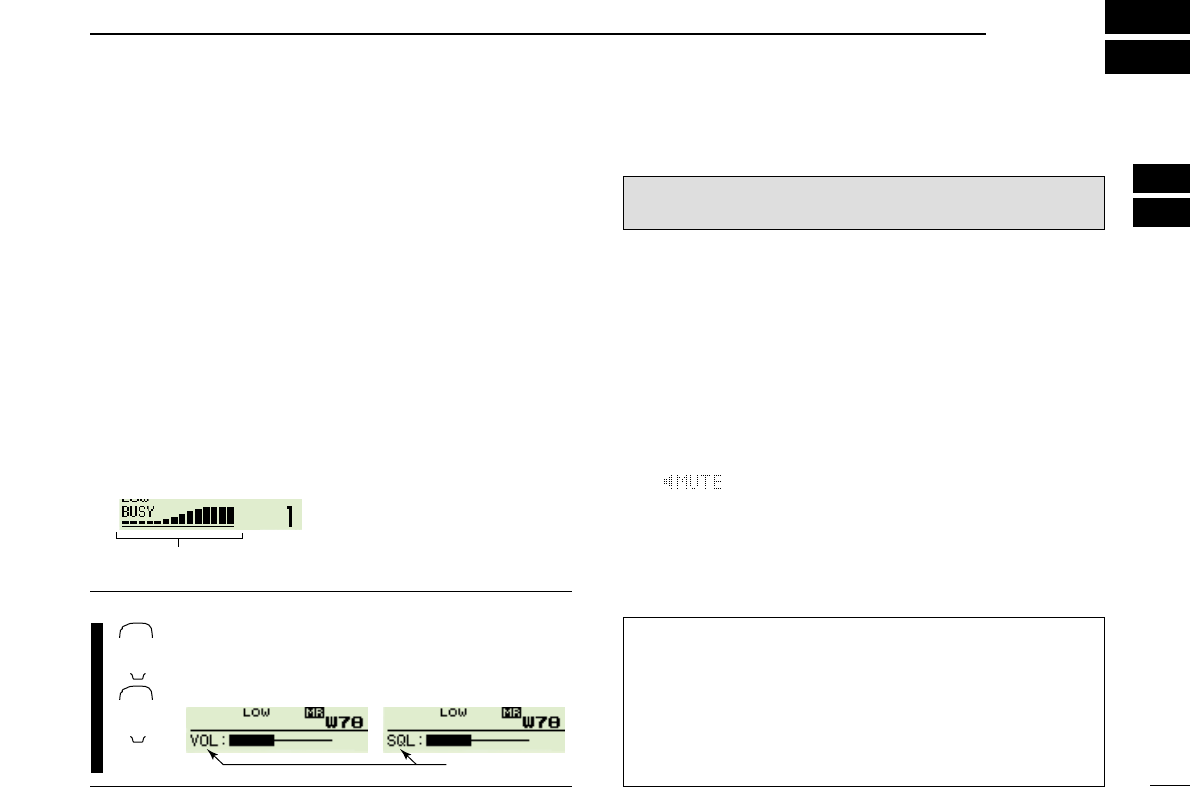
■Receiving
qSet the audio level for the main band.
➥Push the desired band’s [MAIN•BAND].
➥Push and hold [DUP•MONI] for 1 sec. to open the
squelch.
➥Rotate the main band’s [VOL] to adjust the audio level.
➥Push the [DUP•MONI] to close the squelch.
wSet the squelch level.
➥Rotate the main band’s [SQL] fully counterclockwise in
advance, then rotate the [SQL] clockwise until the noise
just disappears.
•When interference due to strong signals is received, rotate
the [SQL] clockwise again for attenuator operation. (p. 17)
eSet the operating frequency in the main band. (pgs. 11–13)
rWhen receiving a signal on the set frequency, squelch
opens and the transceiver emits audio.
•“BUSY” appears and the S/RF
indicator shows the relative
signal strength for the re-
ceived signal.
✔
CONVENIENT!
The main band’s audio and squelch level can also
be adjusted with [
VOL
Y(TONE-1)]/[
VOL
Z0(TONE-2)]
and [
SQL
YD(MUTE)]/[
SQL
Z#(16KEY-L)], respectively.
•“VOL” for audio or “SQL” for squelch appears during set.
■Transmitting
☞NOTE: To prevent interference, listen on the channel be-
fore transmitting by pushing and holding [DUP•MONI] for
1 sec., or [
MONI
1(BANK)] on the microphone.
qSelect the main band. (p. 11)
wSet the operating frequency. (pgs. 11–13)
•Select output power if desired. See section at right for details.
ePush and hold [PTT] to transmit.
•“$” appears.
•The S/RF indicator shows the output power selection.
•A one-touch PTT function is available. See p. ?? for details.
•“ ” appears on the sub band screen according to the se-
lected frequency band.
rSpeak into the microphone using your normal voice level.
•DO NOT hold the microphone too close to your mouth or speak
too loudly. This may distort the signal.
tRelease [PTT] to return to receive.
IMPORTANT! (for 50 W transmission):
The IC-2820H is equipped with protection circuit to protect
the power amplifier circuit from high SWR (Standing Wave
Ratio) and temperature. When a high SWR antenna or no
antenna is connected, or when the transceiver temperature
becomes extremely high, the transceiver reduces transmit
output power to 15 W (approx.) automatically.
CAUTION: Transmitting without an antenna will damage
the transceiver.
Show set level.
SQLY/Z
D/#
VOLY/Z
M/0
Appears when receiving a signal.
21
3BASIC OPERATION
■Selecting output power
The transceiver has 3 output power levels to suit your oper-
ating requirements. Low output powers during short-distance
communications may reduce the possibility of interference to
other stations and will reduce current consumption.
➥Push [LOW•PRIO] several times to select the output
power.
*approx.
•The output power can be changed while transmitting.
The microphone can also be used to select output power.
➥Push [
HIGH
4(DTCS)] for high output power;
[
MID
5(DTCSS)] for middle output power; and
[
LOW
6(DTMF)] for low output power.
•The output power can be changed via the microphone
during receive only.
■Operating mode selection
Operating modes are determined by the modulation of the
radio signals. The transceiver has total 5 operating modes
(FM, FM-N, AM, AM-N and DV modes). The mode selection is
stored independently for each band and memory channel.
Typically, AM mode is used for the air band (118–136.995 MHz).
qPush [F•]to display the function guide.
wPush [MODE](V/MHz•SCAN) (Left band’s) several times to
select the desired operating mode from FM, FM-N, AM,
AM-N and DV.*
*DV mode is available only when the optional UT-123 is installed.
HIGH
4
MID
5
LOW
6
S/RF INDICATOR POWER OUTPUT
VHF/UHF Taiwan
50 W/50 W 25 W
15 W*/15 W* 15 W*
5 W*/5 W* 5 W*
High:
Mid:
Low:
22
3
BASIC OPERATION
1
2
3
4
5
6
7
8
9
10
11
12
13
14
15
16
17
18
19
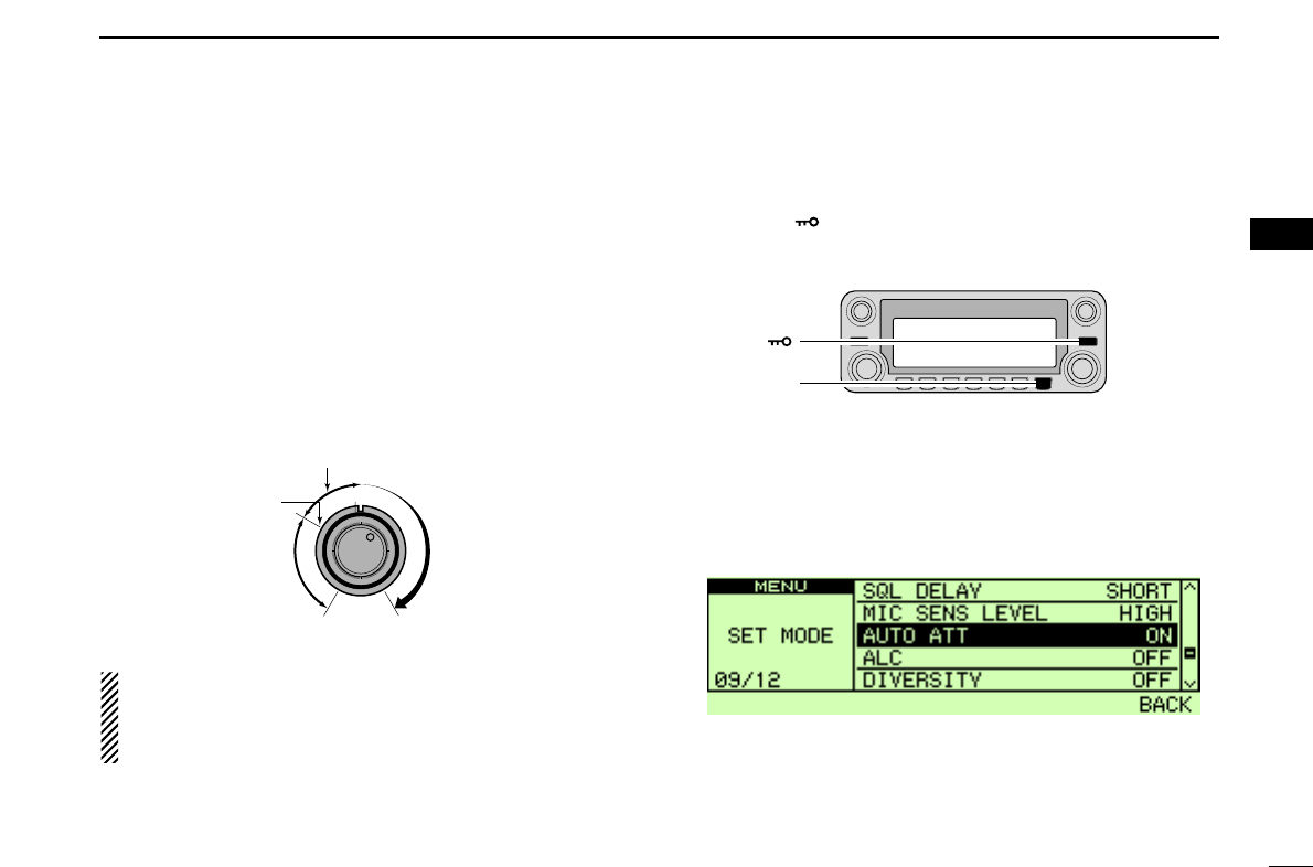
■Squelch attenuator
The transceiver has an RF attenuator related to the squelch
level setting. Approx. 10 dB attenuation is obtained at maxi-
mum setting.
The squelch attenuator allows you to set a minimum signal
level needed to open the squelch. The attenuator function can
be deactivated in set mode.
➥Rotate [SQL] clockwise past the 12 o’clock position to ac-
tivate the squelch attenuator.
•Attenuation level can be adjusted up to 10 dB (approx.) between
12 o’clock and fully clockwise position.
NOTE: The squelch attenuator functions even when the
monitor function is in use. Thus set the [SQL] control
within 10 to 12 o’clock position is recommended when
using the monitor function.
DSquelch attenuator setting
qPush [F•]to display the function guide.
wPush [MENU](V/MHz•SCAN) (Right band’s) to enter MENU
screen.
eRotate the main band’s [DIAL] to select “SET MODE,”
then push [MAIN•BAND] to enter set mode.
rRotate [DIAL] to select “AUTO ATT” then push
[MAIN•BAND].
tRotate [DIAL] to turn the squelch attenuator function ON
and OFF, then push [MAIN•BAND]
•Select “OFF” to deactivate the squelch attenuator function.
yPush [BACK](V/MHz•SCAN) (Right bnd’s) 2 times to exit set
mode.
[F• ]
[MENU]
Squelch is
open.
Squelch
attenuator
Squelch
threshold
Shallow Deep
Noise squelch
23
3BASIC OPERATION
The IC-2820H can simultaneously receive two signals on the
same band, such as 144 MHz band, using the para-watch
function.
qPush and hold either the left or right band’s [MAIN•BAND]
for 1 sec. to select the frequency band selecting condition.
wRotate the same band’s [DIAL] to select the desired fre-
quency band.
ePush the [MAIN•BAND] to return to frequency indication.
rSet the desired frequency.
tRepeat the steps qto rfor the other band (left or right).
To activate the para-watch function from the HM-133, enter
the desired frequencies for each the left and right bands using
the direct frequency input capability via the keypad; or per-
form the following operation.
zPush [BAND] to select the desired band (left or
right) as the main band.
•Push [VFO/LOCK] to select VFO mode, if necessary.
xPush [
ENT
C(T-OFF)] to activate the keypad for
digit input.
cPush 6 keys to input a frequency.
•When a digit is mistakenly input, push [
ENT
C(T-OFF)]
to clear the input, then repeat input from the 1st digit.
vPush [VFO/LOCK] to change main band, then
repeat the steps zto cfor the other band.
NOTE:
•Memory channels are common for the left and right band.
•Transmitting during the para-watch operation is possible.
However, the sub band’s reception is deactivated during
transmit as shown in the example at left.
ENT
C
[Example]
Can be switched
between VHF and
UHF
■V/V, U/U simultaneous receive (Para-watch)
24
3
BASIC OPERATION
1
2
3
4
5
6
7
8
9
10
11
12
13
14
15
16
17
18
19
■Sub band mute/busy beep
The sub band mute function automatically cuts out sub band
audio signals when both main and sub band signals are re-
ceived simultaneously.
While operating on the main band, a beep sounds to inform
you that a signal was received on the sub band.
qPush [F•]to display the function guide.
wPush [MENU](V/MHz•SCAN) (Right band’s) to enter MENU
screen.
eRotate [DIAL] to select “SOUNDS” then push
[MAIN•BAND].
rRotate [DIAL] to select “SUB BAND MUTE” or “SUB
BAND BEEP” then push [MAIN•BAND].
tRotate [DIAL] to turn the sub band mute or sub band beep
function ON and OFF then push [MAIN•BAND].
•Select “OFF” to deactivate the squelch attenuator function.
yPush [BACK](V/MHz•SCAN) (Right bnd’s) 2 times to exit set
mode.
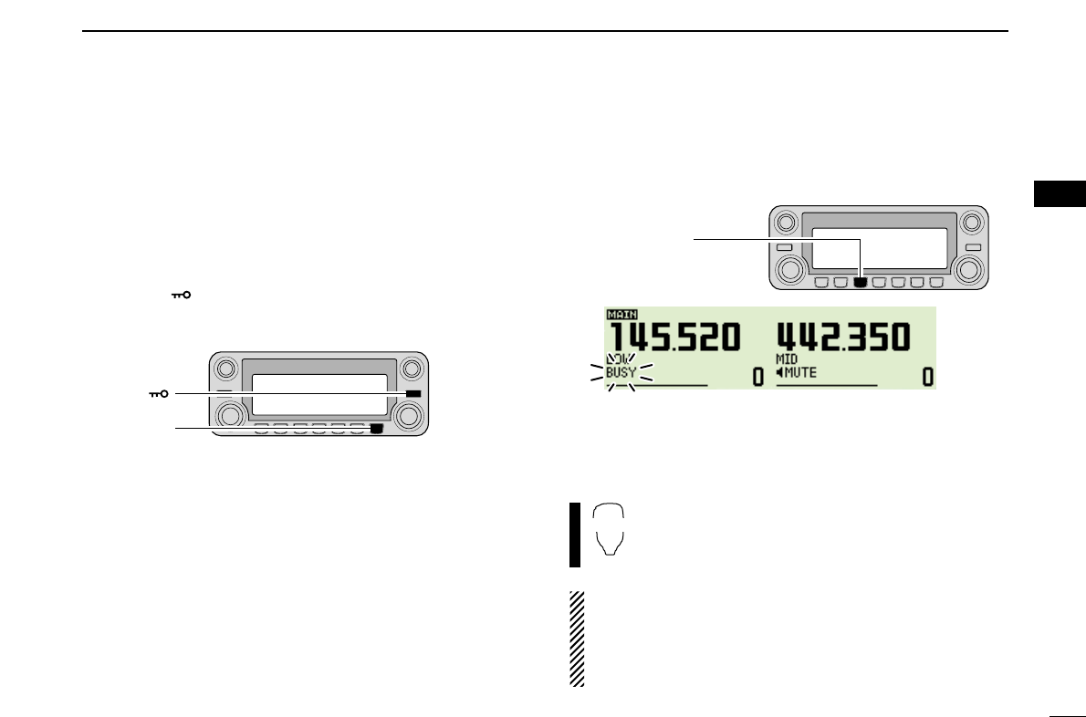
■Monitor function
This function is used to listen to weak signals without disturb-
ing the squelch setting.
➥After pushing [MAIN•BAND],push and hold [DUP•MONI]
for 1 sec. to open the squelch.
•“BUSY” blinks.
•Push [DUP•MONI] again to cancel the function.
➥Push [
MONI
1(BANK)] to open the squelch.
•Push [BAND] to select the desired band (left or right)
as the main band in advance.
•Push [
MONI
1(BANK)] again to cancel the function.
NOTE: When the [SQL] adjustment is set too far clock-
wise, (12–5 o’clock position) the squelch attenuator is acti-
vated. To monitor weak signals on the operating frequency,
deactivate the squelch attenuator function. See pg. ?? for
details.
MONI
1
[DUP•MONI]
[F• ]
[MENU]
25
3BASIC OPERATION
■Single band operation
DDSingle band/Dualwatch operation
Dualwatch operation monitors two frequencies simultane-
ously. The IC-2820H has two independent receiver circuits:
left band, and right band (available frequencies, operating mode
and functions are different depending on bands).
Single band operation is useful when only one frequency is
being watched.
qPush [F•]to display the function guide.
wPush [SNGL](M/CALL•MW) (Right band’s) to select the
signle band operation mode.
•Both left and right band’s [DIAL], [MAIN•BAND], [VOL], [SQL],
[V/MHz•SCAN] and [M/CALL•MW] can be used for operation.
ePush [F•]to display the function guide, then push
[DUAL](M/CALL•MW) (Right band’s) to return to dual watch
operation mode.
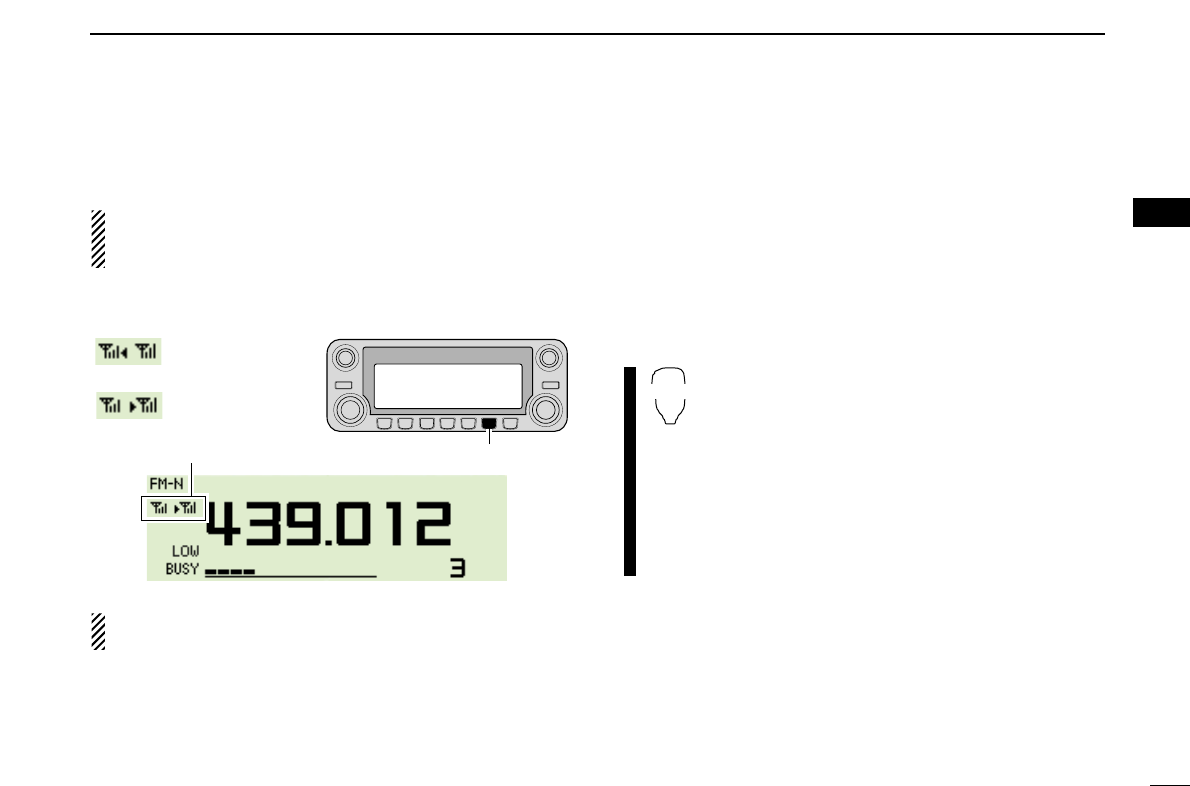
DDDiversity operation
The diversity receiving compares the receiving signal strength
from two different antennas, ANT1 and ANT2, and automati-
cally selects the strongest signal. This feature is useful when
you are listening in a moving vehicle or the transmitting sta-
tion itself is moving. Diversity receiving is available in
127 MHz, 136 MHz, 146 MHz, 375 MHz, 440 MHz and
500 MHz bands only.
qPush [F•]to display the function guide.
wPush [MENU](V/MHz•SCAN) (Right band’s) to enter MENU
screen.
eRotate [DIAL] to select “SET MODE” then push
[MAIN•BAND] to enter set mode.
rRotate [DIAL] to select “DIVERSITY” then push
[MAIN•BAND].
tRotate [DIAL] to select ON, then push [MAIN•BAND].
yPush [BACK](V/MHz•SCAN) (Right band’s) to exit set
mode.
26
3
BASIC OPERATION
1
2
3
4
5
6
7
8
9
10
11
12
13
14
15
16
17
18
19
When the diversity operation is in use, connect the same
grade antenna, connected to [ANT1], shuld be connected
to [ANT2].
➥During single band operation with the diversity function ON,
the diversity indicator appears as below.
With the squelch open in FM mode while receiving a weak
signal, diversity receiving does not work properly.
■One-touch PTT function
The PTT switch can be operated as a one-touch PTT switch
(each push toggles between transmit/receive). Using this
function you can transmit without pushing and holding the
PTT switch.
To prevent accidental, continuous transmissions with this
function, the transceiver has a time-out timer. See p. ?? for
details.
zPush [FUNC] then [
PRIO
3(PTT-M)] to turn the
one-touch PTT function ON.
•The activity indicator lights green.
xPush [PTT] to transmit and push again to re-
ceive.
•A beep sounds when transmission is started and a
long beep sounds when returning to receive.
cPush [FUNC] then [
PRIO
3(PTT-M)] to turn the
one-touch PTT function OFF.
•The activity indicator goes out.
PTT-M
While [ANT2] is
selected;
While [ANT2] is
selected;
Diversity indicator appears. [M/CALL•MW]
27
3BASIC OPERATION
■Audio mute function
This function temporarily mutes the audio without disturbing
the volume setting. (microphone only)
➥Push [FUNC] then [
SQL
YD(MUTE)] to mute
audio signals.
•The “” indicators appear.
•Push [
CLR
A(MW)] (or any other key) to cancel the
function.
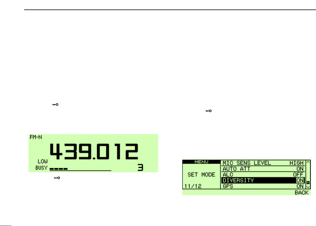
■Band scope
The band scope function allows you to visually check a spec-
ified frequency range around the center frequency.
About the sweep steps: The specified tuning step in each
frequency band (in VFO mode) or programmed tuning step
(in memory mode) is used during sweep.
Sweep markerBand scope indication
Sweep step
indication
The highlighted cursor indication
[M/CALL•MW][DUP•MONI]
[F• ]
[DIAL]
“ ” indicators appear
MUTE

28
3
BASIC OPERATION
1
2
3
4
5
6
7
8
9
10
11
12
13
14
15
16
17
18
19
DDSingle sweep
qSet the desired frequency as band scope center frequency.
wPush [F•]to display the function guide.
ePush [SCP](DUP•MONI) to start a single sweep.
•1 short beep sounds.
•Signal conditions (strengths) appear starting from the lower edge
of the range.
rRotate [DIAL] to set the highlighted cursor to the desired
signal and set the frequency of the signal.
tPush [F•]to display the function guide, then push
[CLR](LOW•PRIO) to clear the band scope indication.
DDContinuous sweep
qSet the desired frequency as band scope center frequency.
wPush [F•]to display the function guide.
ePush and hold [SCP](DUP•MONI) for 1 sec. to start con-
tinuous sweep.
•1 short and 1 long beeps sound.
•Signal conditions (strengths) appear starting from the center of
the range.
rTo stop sweeping, push [F•]to display the function
guide, then push [SCP](DUP•MONI).
tPush [F•]to display the function guide, then push
[CLR](LOW•PRIO) to clear the band scope indication.
The receive audio during sweeping can be muted in
sounds set mode. See page 102 for details.
DDMonitoring a signal
If you find a signal that you want to monitor during/after
sweep, you can monitor the signal with the following opera-
tion.
qPush [F•]to display the function guide, then push
[SCP](DUP•MONI) to cancel the continuousl sweep, if nec-
essary.
wRotate [DIAL] to tune into the desired signal.
ePush [CENT](TONE•DTMF) to return to the center fre-
quency.
REPEATER OPERATION
4
29
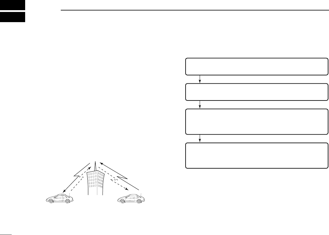
■General
Repeaters allow you to extend the operational range of your
radio because a repeater has much higher output power than
the typical transceiver.
Normally, a repeater has indipendent frequencies for each re-
ceiver and transmitter.
A subaudible tone may also be required to access a repeater
Reference amateur radio hand books and local ham maga-
zines for details of local repeaters such as repeater input/out-
put frequencies and locations.
•Repeater operation flow chart
•The IC-2820H USA version has the auto repeater function. Thus the
steps 3 and 4 may not be necessary, depending on the setting.
•Repeater settings can be stored into a memory channel.
Step 3:
Set the duplex (shifting) direction (– duplex or +duplex).
- Set the offset frequency (shifting value), if required.
Step 4:
Set the subaudible tone (repeater tone) encoder function ON.
- Set the subaudible tone frequency, if required.
Step 1:
Set the desired band to operate the repeater.
Step 2:
Set the desired receive frequency (repeater output frequency).
Repeater example;
Receives the 444.540 MHz signal
and the detected audio signals are
transmitted on 449.540 MHz simul-
taneously.
Station A:
Tx: 444.540 MHz
Rx: 449.540 MHz
Station B:
Tx: 444.540 MHz
Rx: 449.540 MHz
30
4
REPEATER OPERATION
1
2
3
4
5
6
7
8
9
10
11
12
13
14
15
16
17
18
19
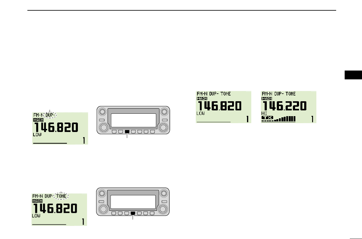
■Accessing a repeater
qSet the receive frequency (repeater output frequency) on
the main band. (pgs. ??–??)
wPush [DUP•MONI] one or two times, to select minus du-
plex or plus duplex.
•“DUP–” or “DUP+” appears to indicate the transmit frequency for
minus shift or plus shift, respectively.
•When the auto repeater function is turned ON (available for the
USA version only), steps wand eare not necessary. (p. ??)
ePush [TONE•DTMF] several times to turn ON the subaudi-
ble tone encoder, according to repeater requirements.
•
“TONE” appears
•88.5 Hz is set as the default; refer to p. ?? for tone frequency set-
tings.
•When the repeater requires a different tone system, see p. ??.
rPush and hold [PTT] to transmit.
•The displayed frequency automatically changes to the transmit
frequency (repeater input frequency).
•If
“OFF” appears, confirm that the offset frequency (p. ??) is set
correctly.
tRelease [PTT] to receive.
yPush [DUP•MONI] to check whether the other station’s
transmit signal can be received directly.
uTo return to simplex operation, push [DUP•MONI] once or
twice, to clear the “DUP–” or “DUP+” indicator.
iTo turn OFF the subaudible tone encoder, push
[TONE•DTMF] several times until no tone indicators ap-
pear.
While receiving While transmitting
[TONE•DTMF]
“TONE” appear
[DUP•MONI]
“DUP–” or “DUP+” appear
31
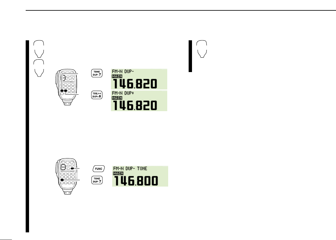
4REPEATER OPERATION
zSet the receive frequency (repeater output fre-
quency) on the main band. (pgs. 11–13)
xPush [
DUP
–7(TONE)] to select minus duplex;
push [
DUP
+ 8(TSQLS)] to select plus duplex.
cPush [FUNC] then [
DUP
–7(TONE)] to turn ON
the subaudible tone encoder according to re-
peater requirements.
•Refer to p. 25 for the tone frequency setting.
•When the repeater requires a different tone system,
see p. 26.
vPush and hold [PTT] to transmit.
bRelease [PTT] to receive.
nPush [
MONI
1(BANK)] to check whether the
other station’s transmit signal can be received
directly.
mPush [
SIMP
9(TSQL)] to return to simplex opera-
tion.
•“DUP” or “DUP–” indicator disappears.
,To turn OFF the subaudible tone encoder, push
[FUNC] then [
ENT
C(T-OFF)].
SIMP
9
Push ,
then .
Push
Push
DUP–
7
DUP+
8
32
4
REPEATER OPERATION
1
2
3
4
5
6
7
8
9
10
11
12
13
14
15
16
17
18
19
■Subaudible tones (Encoder function)
DSubaudible tones
qSelect the main band, mode/channel you wish to set the
subaudible tones to, such as VFO mode or memory/call
channel.
wPush [F•]to display the function guide.
ePush [MENU](V/MHz•SCAN) (Right band’s) to enter MENU
screen.
rRotate [DIAL] to select “DUP/TONE…” then push
[MAIN•BAND].
tRotate [DIAL] to select “REPEATER TONE” then push
[MAIN•BAND].
yRotate [DIAL] to select and set the desired subaudible fre-
quency, then push [MAIN•BAND].
uPush [BACK](V/MHz•SCAN) (Right band’s) twice to exit
DUP/TONE set mode.
☞NOTE: The subaudible tone encoder frequency can be set
in a memory/call channel temporarily. However, the set fre-
quency is cleared once another memory channel or VFO
mode is selected. To store the tone frequency permanently,
overwrite the channel information.
zSet the main band, mode/channel you wish to
set the subaudible tones to, such as VFO mode
or memory/call channel.
•The subaudible tone frequency is independently pro-
grammed into each mode or channel.
xPush [
SET
B(D-OFF)] to enter MENU screen.
cPush [Y] or [Z] to select “DUP/TONE…” then
push [
SET
B(D-OFF)].
vPush [Y] or [Z] to select “REPEATER TONE”
then push [
SET
B(D-OFF)].
bPush [Y] or [Z] to select the desired
subaudible
tone frequency
then push [
SET
B(D-OFF)].
nPush [
CLR
A(MW)] to return VFO mode.
•Subaudible tone frequency list (unit: Hz)
67.0
69.3
71.9
74.4
77.0
79.7
82.5
85.4
88.5
91.5
94.8
97.4
100.0
103.5
107.2
110.9
114.8
118.8
123.0
127.3
131.8
136.5
141.3
146.2
151.4
156.7
159.8
162.2
165.5
167.9
171.3
173.8
177.3
179.9
183.5
186.2
189.9
192.8
196.6
199.5
203.5
206.5
210.7
218.1
225.7
229.1
233.6
241.8
250.3
254.1
Push
SET
B
[V/MHz•SCAN]
[F• ]
[DIAL]
[MAIN•BAND]
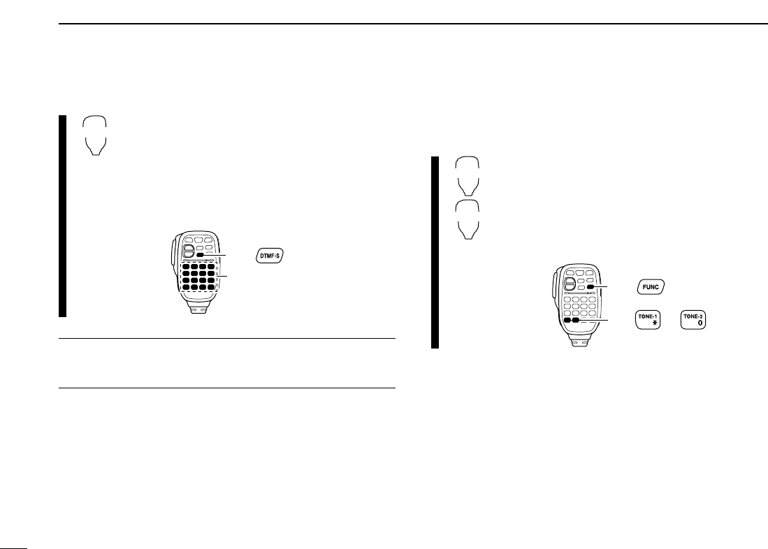
33
4REPEATER OPERATION
DDTMF tones
➥Push [DTMF-S], then push the keys of the de-
sired DTMF digits.
•The function indicator lights green.
•0–9, A–D, ✱(E) and #(F) are available.
•When “1” is displayed, cancel the DTMF memory
encoder in advance. (p. 50)
•Push [DTMF-S] again to return the keypad to nor-
mal function control.
✔
For your convenient!
The transceiver has 16 DTMF memory channels for au-
topatch operation. See p. 48 for details.
D1750 Hz tone
The microphone has 1750 Hz tone capability, used for ring
tone when calling, etc.
zPush [FUNC].
•The function indicator lights orange.
xPush [✱(TONE-1)] to transmit a 1750 Hz tone
call signal for 0.5 sec.; push and hold
[0(TONE-2)] to transmit a 1750 Hz tone call
signal for an arbitrary period.
•The function indicator goes out automatically.
Push ,
then or .
TONE-1
TONE-2
then push desired keys.
Push ,
DTMF-S
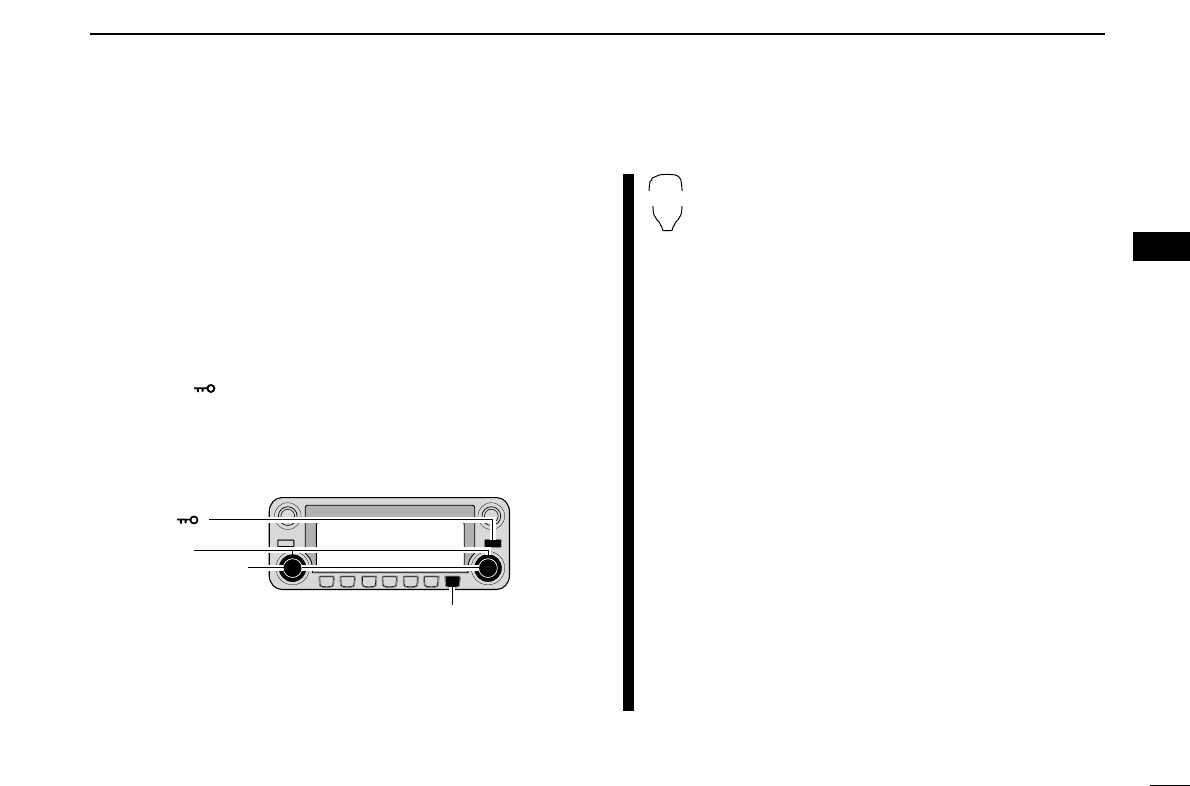
34
4
REPEATER OPERATION
1
2
3
4
5
6
7
8
9
10
11
12
13
14
15
16
17
18
19
■Offset frequency
When communicating through a repeater, the transmit fre-
quency is shifted from the receive frequency by an amount
determined by the offset frequency.
Independent offset frequencies can be set for each operating
frequency band.
qPush [MAIN•BAND] to select the desired band (left or right)
as the main band.
wSelect the desired mode/channel you wish to set the offset
frequency to, such as VFO mode or memory/call channel.
rPush [F•]to display the function guide then push
[MENU](V/MHz•SCAN) (Right band’s) to enter MENU
screen.
tRotate the [DIAL] to select “DUP/TONE…”, then push
[MAIN•BAND].
yRotate the [DIAL] to select “OFFSET FREQ” item, then
push [MAIN•BAND].
uRotate the main band’s [DIAL] to set the desired offset fre-
quency.
iPush [BACK](V/MHz•SCAN) (Right band’s) twice to exit
DUP/TONE set mode.
zPush [BAND] to select the desired band (left or
right) as the main band.
•Enter the desired frequency via the keypad if neces-
sary.
xSelect the desired mode/channel you wish to
set the offset frequency to, such as VFO mode
or memory/call channel.
•The offset frequency can be independently pro-
grammed into each mode or channel.
c
Push [
SET
B(D-OFF)] to enter MENU screen.
v
Push
[Y] or [Z] to select “DUP/TONE…” then
push
[
SET
B(D-OFF)].
v
Push
[Y] or [Z] to select “OFFSET FREQ” then
push
[
SET
B(D-OFF)].
bPush [Y] or [Z] to set the desired
offset.
•Direct frequency entry from the keypad is not possi-
ble.
nPush [
CLR
A(MW)] to exit set mode.
☞NOTE: The offset frequency can be set in a
memory/call channel temporarily. However, the
set frequency is cleared once another memory
channel or VFO mode is selected. To store the
offset frequency permanently, overwrite the
channel information.
SET
B
[V/MHz•SCAN]
[F• ]
[DIAL]
[MAIN•BAND]
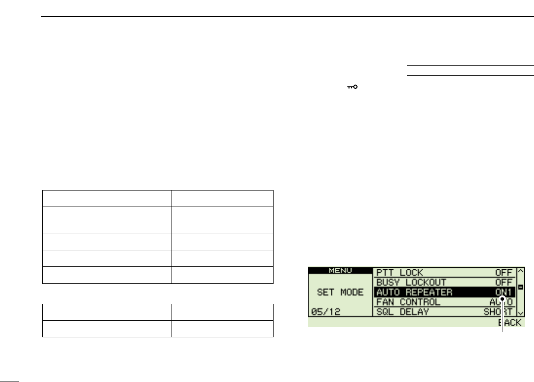
35
4REPEATER OPERATION
The U.S.A. and Korean versions automatically use standard
repeater settings (duplex ON/OFF, duplex direction, tone encoder
ON/OFF) when the operating frequency falls within or outside
of the general repeater output frequency range. The offset
and repeater tone frequencies are not changed by the auto
repeater function, reset these frequencies, if necessary.
DFrequency range and offset direction
•U.S.A. version
•Korean version
qPush [F•]to display the function guide.
wPush [MENU](V/MHz•SCAN) (Right band’s) to enter MENU
screen.
eRotate [DIAL] to select “SET MODE” then push
[MAIN•BAND].
rRotate [DIAL] to select “AUTO REPEATER” then push
[MAIN•BAND].
tRotate [DIAL] to select the auto repeater setting.
[U.S.A. version]:
•“ON1”: Activates duplex only. (default)
•“ON2”: Activates duplex and tone.
•“OFF”: Auto repeater function is turned OFF.
[Korean version]:
•“ON”: Activates duplex and tone. (default)
•“OFF”: Auto repeater function is turned OFF.
yPush [BACK](V/MHz•SCAN) (Right band’s) twice to exit
from set mode.
Auto Repeater set: ON1
(USA version)
FREQUENCY RANGE SHIFT DIRECTION
439.000–440.000 MHz “DUP–” appears
FREQUENCY RANGE SHIFT DIRECTION
147.000–147.395 MHz “DUP+” appears
442.000–444.995 MHz “DUP+” appears
447.000–449.995 MHz “DUP–” appears
145.200–145.495 MHz
146.610–146.995 MHz “DUP–” appears
■Auto repeater U.S.A./KOREAN versions only

36
4
REPEATER OPERATION
1
2
3
4
5
6
7
8
9
10
11
12
13
14
15
16
17
18
19
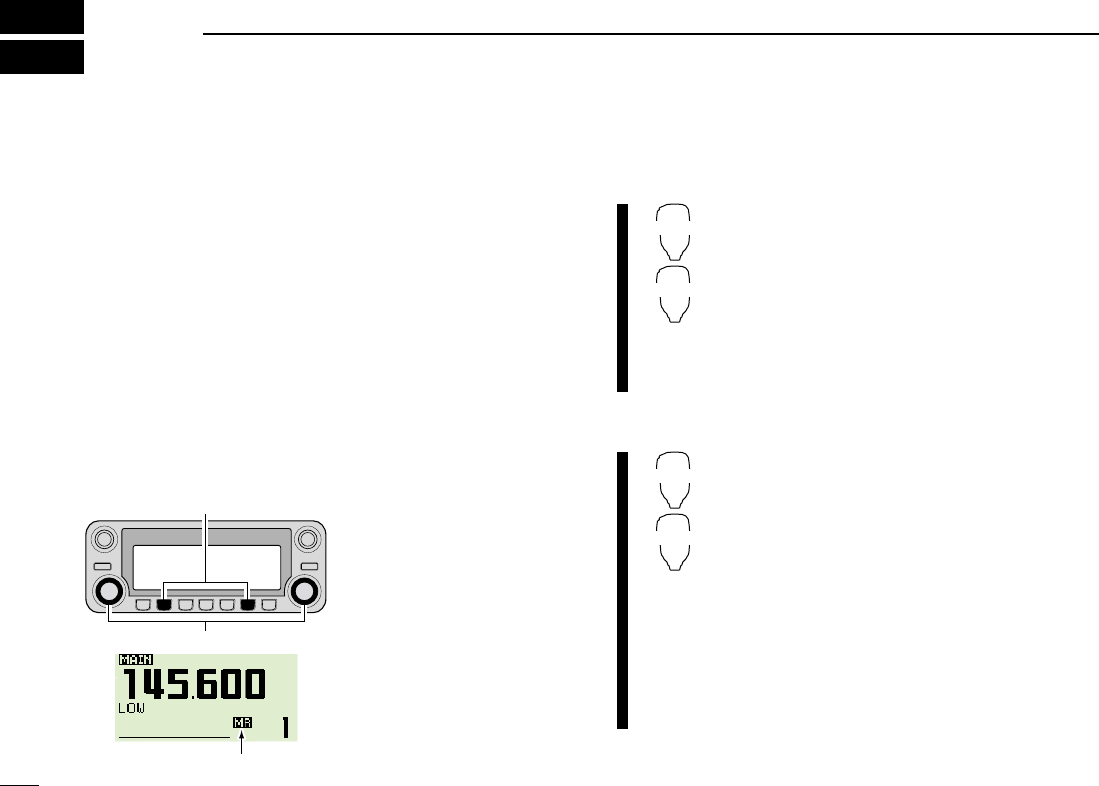
37
MEMORY OPERATION
5
■General description
The transceiver has 522 memory channels including 20 scan
edge memory channels (10 pairs), and 2 call channels. Each
of these channels can be individually programmed with oper-
ating frequency (pgs. ??–??), duplex direction (p. ??) and offset
(p. ??), subaudible tone encoder or tone squelch and its tone
frequency (pgs. ??, ??, ??, ??) and skip information* (p. ??).
In addition, a total of 26 memory banks, A to Z, are available
for usage by group, etc.
*except for scan edge memory channels.
■Memory channel selection
DUsing the tuning dial
qPush the desired band’s
[M/CALL•MW] several
times to select memory
mode.
•“X” indicator appear
wRotate the same band’s
[DIAL] to select the de-
sired memory channel.
•Programmed memory
channels only can be se-
lected.
DUsing the [Y]/[Z] keys
zPush [BAND] to select the desired band as
the main band.
xPush [MR/CALL] to select memory mode.
cPush [Y] or [Z] to select and set the desired
memory channel.
•Pushing and holding [Y]/[Z] for 1 sec. activates
a scan.
•If scan is activated, push [Y]/[Z] again or push
[
CLR
A(MW)] to stop it.
DUsing the keypad
zPush [BAND] to select the desired band as
the main band.
xPush [MR/CALL] to select memory mode.
cPush [
ENT
C(T-OFF)] to activate the keypad
for numeral input.
vPush 3 appropriate digit keys to input a chan-
nel number.
•Blank channel can be selected.
•Push only 1 appropriate digit key, [
VOL
Y0(TONE-
2)] to [
SIMP
9(16-KEY-L)]] then push [MM(TONE-1)]
or [
SQL
Z#(16KEY-L)] to select scan edge chan-
nels. “MM” and “#” can be used for “A” and “b” re-
spectively.
MR/CALL
Y/Z
MR/CALL
Y/Z
[M/CALL•MW]
[DIAL]
åXßappears
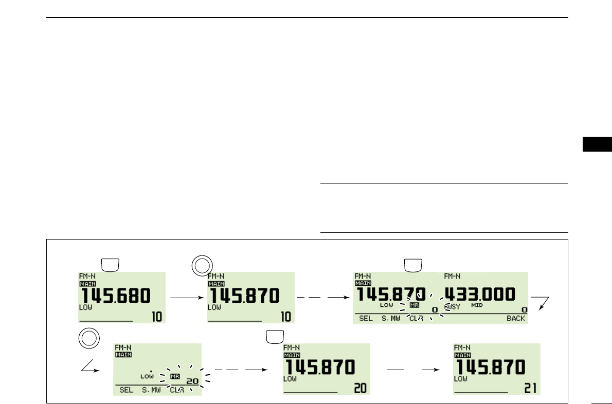
VFO settings, including MENU group’s contents such as sub-
audible tone frequency, offset, can be programmed into a
memory channel.
qSet the desired frequency in the desired band (left or right).
➥Push the desired band’s [V/MHz•SCAN] to select VFO
mode.
➥Set the frequency using the same band’s [DIAL].
➥Set other data (e.g. tone frequency, duplex information, etc.)
if required.
wPush and hold the same band’s [M/CALL•MW] for 1 sec.
•2 beeps sound
•“X” indicator and the memory channel number blink.
eRotate the [DIAL] to select the memory channel to be pro-
grammed.
•Memory channels not yet programmed are blank.
rPush and hold the same band’s [M/CALL•MW] for 1 sec.
to program.
•3 beeps sound
•Memory channel number automatically increases when contin-
uing to push [M/CALL•MW] after programming.
✔CONVENIENT
Memory programming can be performed in versatile ways
e.g. memory channel to the same (or different) memory chan-
nel, memory channel to the call channel, etc.
38
5
MEMORY OPERATION
1
2
3
4
5
6
7
8
9
10
11
12
13
14
15
16
17
18
19
■Programming a memory channel
[EXAMPLE]: Programming 145.870 MHz into memory channel 20 (blank channel) via the controller.
Push Rotate for setting frequency, etc. Push and hold for 1 sec.
Rotate Push and hold for 1 sec. and continue to push
➠
Beep
“
V/MHz
SCAN
M/CALL
MW
M/CALL
MW
B
A
N
D
M
A
I
N
B
A
N
D
M
A
I
N
Beep
Beep
Beep
“
“
“
“
“
Beep
Beep
“
“
“
“
“
DProgramming a memory channel via the microphone
The microphone can also be used to program mem-
ory channels.
zSet the desired frequency in VFO mode.
➥Push [VFO/LOCK] to select VFO mode.
➥Set the frequency using the keypad.
➥Set other data (e.g. offset frequency, duplex direction, sub-
audible tone encoder ON/OFF and its frequency), if neces-
sary.
xPush [MR/CALL] to enter memory mode.
cPush [
ENT
C(T-OFF)], then set the desired memory chan-
nel using the keypad.
vPush [VFO/LOCK] to select VFO mode.
bPush [FUNC] then push and hold [
CLR
A(MW)] for 1 sec. to
program.
➥3 beeps may sound and the VFO contents (including the
subaudible tone frequency, etc.) are programmed.
➥Memory channel number increases when continuing to
push [
CLR
A(MW)] after programming.
MW
39
5MEMORY OPERATION
[EXAMPLE]: Programming 145.870 MHz into memory channel 20 (blank channel) via the microphone.
Beep
“
Beep
“
Beep
Beep
Beep
“
“
“
“
“
Push ,
Push then for 1 sec. and continue to push
➠
MR/
CALL
Push then Push
Push
40
5
MEMORY OPERATION
1
2
3
4
5
6
7
8
9
10
11
12
13
14
15
16
17
18
19
■Memory bank selection
The IC-2820H has a total of 26 banks (A to Z). All memory
channels, regular, scan edges and call channels are assigned
into the desired bank for easy memory management.
qPush the desired band’s [M/CALL•MW] several times to
select memory mode, if desired.
wPush and hold the same band’s [MAIN•BAND] for 1 sec.
• The memory channel number blinks.
eRotate the same band’s [DIAL] to select the desired bank,
A to Z.
•Banks that have no programmed contents are skipped.
rPush the [MAIN•BAND] to set the bank group.
•Bank initial and bank channel stop blinking.
tRotate the same band’s [DIAL] to select the bank channel.
yTo return to regular memory mode, push and hold the
[MAIN•BAND] for 1 sec. then rotate the [DIAL] to select
memory channel number indication.
zPush [MR/CALL] to select memory mode, if de-
sired.
xPush [FUNC] then [
MONI
1(BANK)] to select
memory bank condition.
Or, push and hold [BAND] for 1 sec. to select
memory bank condition.
•Memory channel blinks
cPush [Y]/[Z] to select the desired bank, A to Z.
•Only programmed memory bank can be selected.
vPush [
CLR
A(MW)] to set the bank.
Or, push [BAND] to set the bank.
•Bank initial and bank channel stops blinking.
bPush [Y]/[Z] to select the desired contents in
the bank.
•No channel numbers are displayed for memory bank
operation.
nTo return to regular memory condition, push
[FUNC], [
MONI
1(BANK)] then push [Y]/[Z] to
select memory channel number indication.
Or, push and hold [BAND] for 1 sec., then push
[Y]/[Z] to select memory channel number indi-
cation.
BANK
[Y]/[Z]
Bank initial and bank
channel blink
Enter the memory bank condition mode.
[MAIN•BAND]
41
5MEMORY OPERATION
■Memory bank setting
qPush the desired band’s [M/CALL•MW] several times to
select memory mode, then rotate the same band’s [DIAL]
to select the desired memory channel.
wPush and hold the same band’s [M/CALL•MW] for 1 sec.
•“X” and memory number indication blinks.
ePush [SEL](V/MHz•SCAN) (Left band’s) several times to se-
lect “BANK” setting stand-by condition.
•“X” indicator blinks.
rPush [EDIT](M/CALL•MW) (Right band’s) to edit.
•“X” and 1st digit blink.
tRotate the same band’s [DIAL] to select the desired bank
group.
•A to Z bank groups available.
yPush [>](M/CALL•MW) (Left band’s) then rotate [DIAL] to
select the desired bank channel.
•“X” and last 2 digits blink.
uPush [BACK](V/MHz•SCAN) (Right band’s) to set the bank
initial and channel number.
•“X” indicator blinks.
iPush and hold [S.MW](M/CALL•MW) (Left band’s) for 1 sec.
to overwrite the memory channel to store the memory bank
settings.
oRepeat steps qto ito set another memory channel into
the same or another bank.
42
5
MEMORY OPERATION
1
2
3
4
5
6
7
8
9
10
11
12
13
14
15
16
17
18
19
■Programming memory/bank/scan name
Each memory channel can be programmed with an alphanu-
meric channel name for easy recognition and can be indi-
cated independently by channel. Names can be a maximum
of 8 characters— see the table right below for available char-
acters.
qSelect the desired memory channel to be programmed.
➥Push [M/CALL•MW] several times to select memory
mode, then rotate the same band’s [DIAL] to select the
desired memory channel.
wPush and hold the same band’s [M/CALL•MW] for 1 sec.
to enter select memory write mode.
•“X” indicator and the memory channel number blink.
ePush [SEL](V/MHz•SCAN) (Left band’s) several times to se-
lect programming the name conditions.
“BANK”: The memory bank
“B NAME”: The bank name (appears only when the selected
memory bank is edited into a bank)
“M NAME”: The memory name
“S NAME”: The scan name (appears only when a scan edge
channel is selected)
•Frequency readouts disappear.
rPush [EDIT](M/CALL•MW) (Right band’s) to edit.
•“X” indicator and cursor blinks.
tRotate the same band’s [DIAL] to select the desired char-
acter.
•The selected character blinks.
•Push [Aa](TONE•DTMF) to turn the character group from al-
phabetical characters capital letters or lower case letters.
•Push [12](M/CALL•MW) (Right band’s) to turn the character group
from numbers or symbols.
•Push [>](M/CALL•MW) (Left band’s) to move the cursor right;
push [<](V/MHz•SCAN) (Left band’s) to move the cursor left.
•Push [CLR](DUP/MONI) to clear the selected character.
yRepeat steps eand tuntil the desired channel name is
programmed.
uPush [BACK](V/MHz•SCAN) (Right band’s) to set the name.
yPush and hold [S.MW](M/CALL•MW) (Right band’s) for
1 sec. to overwrite the memory channel to store the mem-
ory name.
NOTE: Only one bank name can be programmed into
each bank. Therefore, the previously programmed bank
name will be displayed when bank name indication is se-
lected. Also, the programmed bank name is assigned for
the other bank channels automatically.
DDAvailable characters
ABCDEFGHIJKLMNOPQRSTUVWXYZ
abcdefghijklmnopqrstuvwxyz
0123456789
(Space)! ''#$%&'()*+,-
./:;<=>?@[\]^_`{|}~
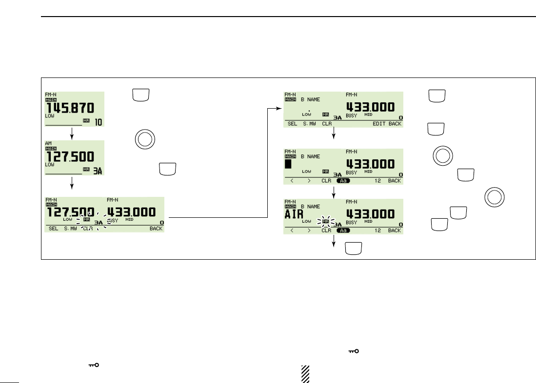
43
5MEMORY OPERATION
[EXAMPLE]: Programming the bank name “AIR” into the scan edge channel 3A.
Enter “I” and “R” with (Main
band's) and (Left band's), then
push (Right band's) to select
memory write mode.
V/MHz
SCAN
V/MHz
SCAN
M/CALL
MW
M/CALL
MW
Push and hold (Left band's) for 1 sec. to program.
M/CALL
MW
M/CALL
MW
Push (Main band's) to select memory mode.
B
A
N
D
M
A
I
N
Rotate (Main band's) to select scan edge
channel 3A.
B
A
N
D
M
A
I
N
B
A
N
D
M
A
I
N
Rotate (Main band's) to select
“A”, then push .
M/CALL
MW
M/CALL
MW
Push and hold (Main band's) for 1 sec.
to enter select memory write condition.
Push (Main band's) several times
to select “B NAME”.
Push (Right band's) to enter bank
name edit mode.
*Select “M NAME” or “S NAME” when programing the memory name or the
scan name, respectively.
Bank name edit mode
Select memory write mode
Memory mode SEL
EDIT
DDTo indicate the channel name
The channel name indication can be set independently for
each memory channel.
qSelect the desired memory channel in the main band.
➥Push the same band’s [M/CALL•MW] several times to
select memory mode, then rotate the same band’s [DIAL]
to select the desired memory channel.
•“X” and memory channel number appear.
wPush [F•]to display the function guide.
ePush [M.N](LOW•PRIO) several times to select “MEM-
ORY,” “FREQ” or OFF.
•When “MEMORY” is selected, the programmed memory name is
indicated above frequency indication; when “FREQ” is selecte,
the programmed memory name is indicated at the frequency in-
dication and the programmed frequency is indicated above the
memory name.
rPush [F•]twice to exit the function guide.
NOTE: When no memory name is programmed, the stored
frequency is displayed.
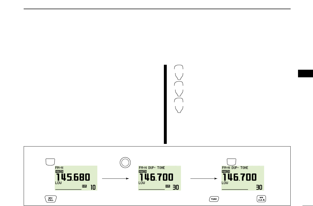
■Transferring memory contents
This function transfers a memory channel’s contents to VFO
(or another memory/call channel). This is useful when searching
for signals around a memory channel frequency and for re-
calling the offset frequency, subaudible tone frequency etc.
DMemory/call➪VFO
qSelect the desired band’s (left or right) memory or call chan-
nel.
➥Push the desired band’s [M/CALL•MW] several times to
select memory mode or call channel, then rotate the
same band’s [DIAL] to select the desired memory or call
channel.
wPush and hold [M/CALL•MW] for 1 sec. to transfer the se-
lected memory/call channel contents to the VFO.
•VFO mode is selected automatically.
zPush [BAND] to select the desired band as
the main band, if necessary.
xSelect the memory/call channel to be
transferred.
➥Push [MR/CALL] to select memory mode,
then select the desired memory channel
via [Y]/[Z] or keypad.
➥Push and hold [MR/CALL] for 1 sec. then
push [Y]/[Z] to select the call channel.
cPush [FUNC], then push and hold
[
CLR
A(MW)] for 1 sec. to transfer the se-
lected memory/call channel contents to the
VFO.
•VFO mode is selected automatically.
MR/CALL
MW
[Y]/[Z]
44
5
MEMORY OPERATION
1
2
3
4
5
6
7
8
9
10
11
12
13
14
15
16
17
18
19
[EXAMPLE]: Transferring memory channel 30 contents to VFO.
Push to select memory mode.
Front panel operation:
HM-133 operation:
Push to select memory mode.
Rotate for selecting memory channel.
Select memory channel.
Push and hold (same band’s) for 1 sec.
Push then push and hold for 1 sec.
M/CALL
MW
M/CALL
MW
B
A
N
D
M
A
I
N
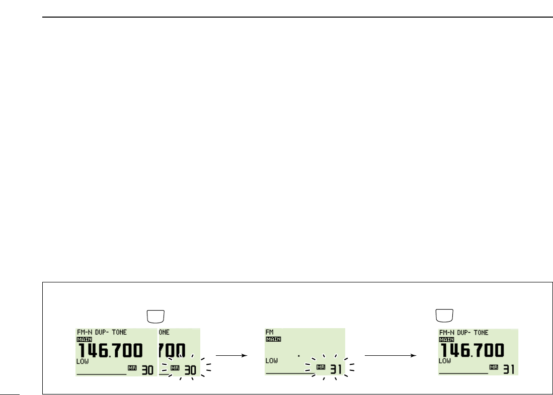
45
5MEMORY OPERATION
DMemory/call➪call/memory
qSelect the memory/call channel to be transferred.
➥Push the desired band’s [M/CALL•MW] several times
to select memory mode or call channel, then rotate the
same band’s [DIAL] to select the desired memory or
call channel.
wPush and hold the same band’s [M/CALL•MW] for 1 sec.
•“X” indicator and the memory channel number blink, and
shows VFO conditions.
eRotate the same band’s [DIAL] to select the target memory
channel.
•“C1” or “C2” blinks when the call channel is selected.
•Scan edge channels, 1A/1b, 2A/2b, 3A/3b, 4A/4B, 5A/5b can
also be selected.
rPush and hold the [S.MW](M/CALL•MW) (Left band’s) for
1 sec. to transfer the selected memory/call channel con-
tents to the target memory.
•The targeted memory and transferred contents are indicated.
[EXAMPLE]: Transferring memory channel 30 contents to channel 31.
Select the target channel.
Select the memory channel,
then push and hold for 1sec. Push and hold for 1 sec.
M/CALL
MW
M/CALL
MW
S.MW
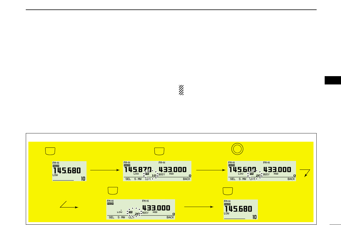
46
5
MEMORY OPERATION
1
2
3
4
5
6
7
8
9
10
11
12
13
14
15
16
17
18
19
■Memory clearing
Contents of programmed memories can be cleared (blanked),
if desired.
qPush [V/MHz•SCAN] to select VFO mode in the desired
band (left or right).
wPush and hold the same band’s [M/CALL•MW] for 1sec.
•“X” indicator and the memory channel number blink.
eRotate [DIAL] to select the memory channel to be cleared.
rPush and hold [CLR](DUP•MONI) for 1sec. to clear.
•3 beeps sound, then the frequency is cleared.
•“X” indicator and the channel number blink continuously.
•When clearing the call channel, the current VFO conditions are
re-programmed into the call channel automatically.
tPush [BACK](V/MHz•SCAN) (Right band’s) to return to VFO
mode.
NOTE: Be careful!— the contents of cleared memories
CANNOT be recalled.
[EXAMPLE]: Clearing memory channel 20.
Push (Main band’s) to select VFO. Rotate (Main band’s) for selecting
memory channel to be cleared.
Push and hold (Main band’s) for 1 sec.
Push .
V/MHz
SCAN
V/MHz
SCAN
M/CALL
MW
Push and hold for 1 sec. memory clearing.
DUP
MONI
B
A
N
D
M
A
I
N
Beep
Beep
Beep
“
“
“
“
“
CLR BACK
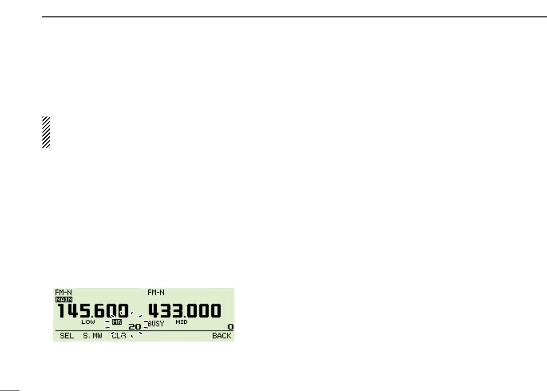
47
5MEMORY OPERATION
Contents of programmed memory banks can be cleared or
transferred to another bank.
INFORMATION: Even if the memory bank contents are
cleared, the memory channel contents still remain pro-
grammed.
qSelect the desired bank contents to be transferred or
erased from the band (left or right).
➥Push the desired band’s [M/CALL•MW] several times
to select memory mode.
➥Push and hold the same band’s [MAIN•BAND] for
1 sec. then rotate the same band’s [DIAL] to select the
desired memory bank.
➥Push the [MAIN•BAND] to select the bank then rotate
the [DIAL] to select the desired bank channel.
•Bank initial and bank channel stops blinking.
wPush and hold the same band’s [M/CALL•MW] for 1 sec.
•“X” indicator and the memory channel number blink
ePush [SEL](V/MHz•SCAN) (Left band’s) several times to se-
lect bank, then push [EDIT](M/CALL•MW) (Right band’s).
rRotate [DIAL] to select the desired bank initial (A to Z) to
transfer.
•Select no indication, “– – – –,” when erasing the contents from
the bank.
tPush [>](M/CALL•MW) (Left band’s) then rotate the same
band’s [DIAL] to select a bank channel, if desired.
yPush [BACK](V/MHz•SCAN) (Right band’s) to back the se-
lect memory write mode.
uPush and hold [S.MW](M/CALL•MW) (Left band’s) for 1 sec.
to be transferred or erased.
iRepeat steps qto tfor transferring or erasing an another
banks contents.
■Erasing/transferring bank contents
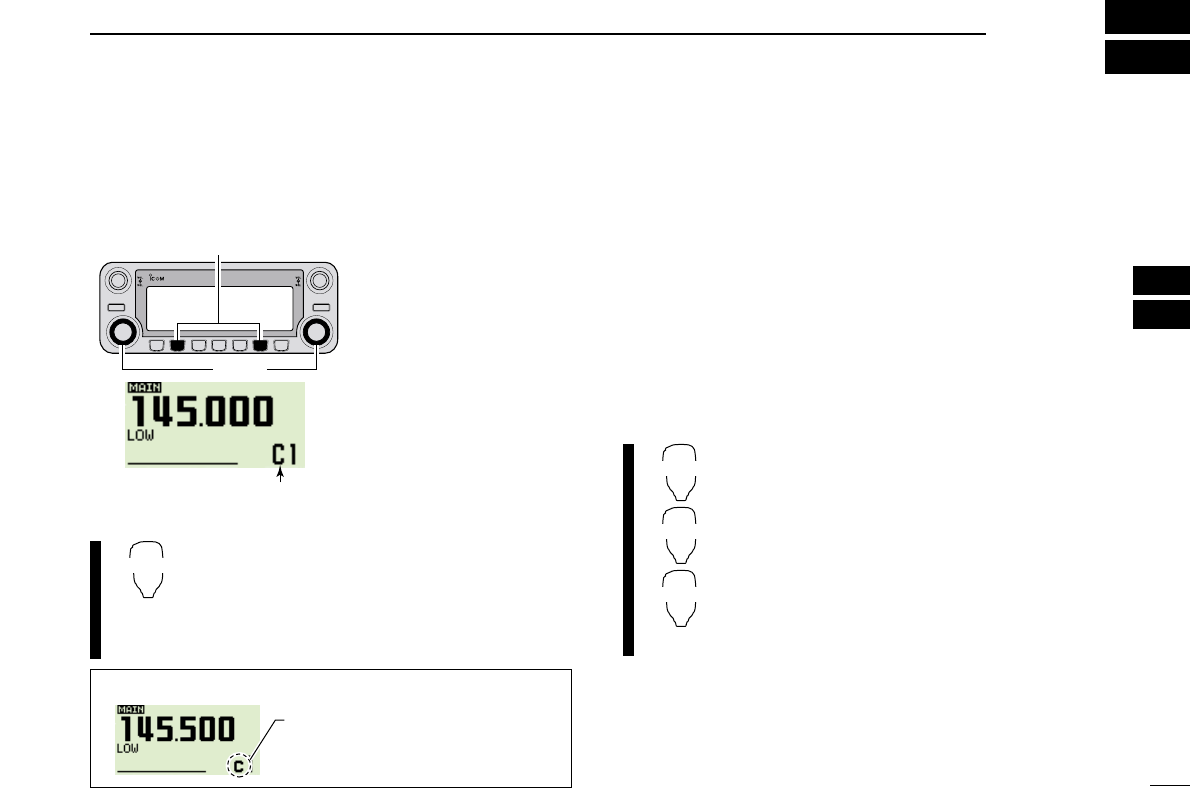
48
6
CALL CHANNEL OPERATION
1
2
3
4
5
6
7
8
9
10
11
12
13
14
15
16
17
18
19
■Call channel selection
Call channel is pre-programmed memory channel that can be
accessed by simply pushing call channel button.
➥Push [M/CALL•MW] sev-
eral times to select the
call channel mode then
rotate the same band’s
[DIAL] to select the de-
sired call channel.
•“C0” or “C1” appears in-
stead of memory channel
number indication.
•Push the [M/CALL•MW]
several times to select mem-
ory mode, or push the same
band’s [V/MHz•SCAN] to se-
lect VFO mode.
➥Push and hold [MR/CALL] for 1 sec. to select
the call channel mode then push [Y]/[Z] to
select the desired call channel in the main
band.
•Push [MR/CALL] to select memory mode, or push
[VFO/LOCK] to select VFO mode.
■Call channel transferring
DCall➪VFO/Memory
qPush the desired band’s [M/CALL•MW] several times to
select cal channel mode, then rotate the same band’s
[DIAL] to select the desired call channel.
•“C0” or “C1” appears.
wPush the [M/CALL•MW] for 1 sec., then rotate the [DIAL]
to select the memory channel to transfer the contents to.
•“X” indicator and memory channel number blink.
•To transfer to the VFO mode, select VFO indication with the
[DIAL].
ePush the [M/CALL•MW] for 1 sec. to transfer the contents.
zPush [MR/CALL] for 1 sec. then push [Y]/[Z]
to select the desired call channel in the main
band.
xPush [FUNC], then [
CLR
A(MW)] for 1 sec. to
transfer the contents.
•To transfer to the VFO only.
MR/CALL
MW
[Y]/[Z]
MR/CALL
DUO BAND TRANSCEIVER i2820
“C0” or “C1” appears
[DIAL]
[M/CALL•MW]
✔INFORMATION
When the VFO mode is selected from
the call channel, a small “c” appears
instead of memory channel number.
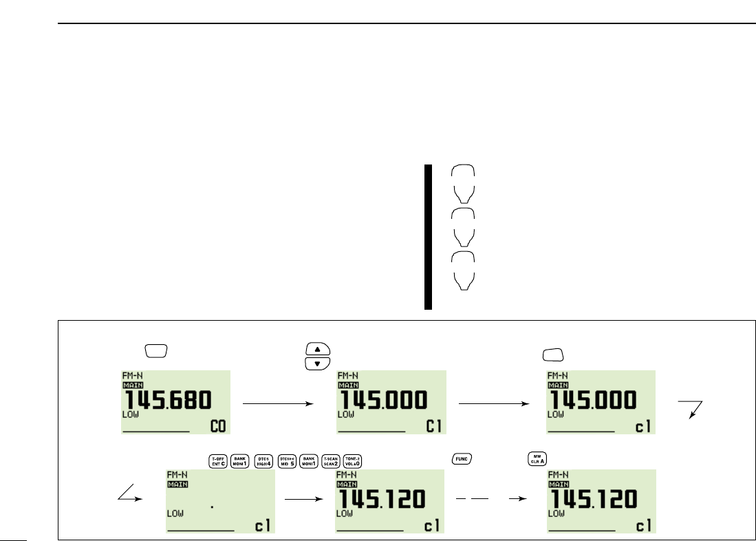
49
6CALL CHANNEL OPERATION
■Programming a call channel
Operating frequency, duplex information, subaudible tone in-
formation (tone encoder or tone squelch ON/OFF and its fre-
quency) can be programmed into the call channel.
qSet the desired frequency in VFO mode.
➥Push the desired band’s [V/MHz•SCAN] to select VFO
mode.
➥Set the frequency using the same band’s [DIAL].
➥Set other data as desired.
wPush the same band’s [M/CALL•MW] for 1 sec.
eRotate the [DIAL] to select the desired call channel.
•“X” indicator and “C0” or “C1” blink.
rPush the [M/CALL•MW] for 1 sec. to program.
•3 beeps sound and the unit returns to VFO mode automatically.
zPush and hold [MR/CALL] for 1 sec. to select
call channel mode.
➥Push [Y] or [Z] to select desired call chan-
nel.
x
Push [
VFO/LOCK] to select VFO mode
.
➥Set the frequency.
cPush [FUNC] then [
CLR
A(MW)] for 1 sec. to
program.
•3 beeps sound.
MR/CALL
MW
[Y]/[Z]
[EXAMPLE]: Programming 145.120 MHz into the call channel 1 via the microphone.
Push , then push for 1 sec.
➠
Push to select the call channel “C1”.
Beep
Beep
Beep
“
“
“
“
“
Set the frequency.
Push and hold for 1 sec. to
select call channel mode.
MR/
CALL Push to select VFO mode.
VFO/
LOCK
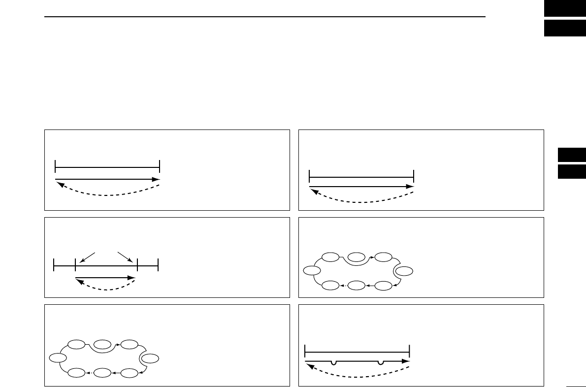
50
7
SCAN OPERATION
1
2
3
4
5
6
7
8
9
10
11
12
13
14
15
16
17
18
19
■Scan types
Scanning searches for signals automatically and makes it
easier to locate new stations for contact or listening purposes.
There are 7 scan types and 4 resume conditions to suit your
operating needs.
FULL SCAN (p. ??)Repeatedly scans all frequen-
cies over the entire band.
Some frequency ranges are
not scanned according to the
frequency coverage of the
transceiver’s version.
495
kHz
999.990
MHz
Scan
Jump
SELECTED BAND SCAN
(p. ??)
Repeatedly scans all frequen-
cies over the entire selected
band.
Band
edge
Band
edge
Scan
Jump
ALL/SELECTED BANK
SCAN (p. ??)
Repeatedly scans all bank
channels or selected bank
channels. The skip scan is
also available.
SKIP
SKIP
A99 A03
A00 A01 A02
A04
A98
A05
FREQUENCY/MEMORY
SKIP FUNCTION (p. ??)
Skips unwanted frequencies
or channels that inconve-
niently stop scanning. This
function can be turned ON
and OFF by pushing and
holding [SKIP](5) in either
VFO or memory mode.
Band
edge
Band
edge
Scan
SKIP SKIP
Jump
PROGRAMMED SCAN
(p. ??)
Repeatedly scans between
two user-programmed fre-
quencies. Used for checking
for frequencies within a speci-
fied range such as repeater
output frequencies, etc.
Band
edge xxA xxB
Band
edge
Scan edges
Scan
Jump
MEMORY (SKIP) SCAN
(p. ??)
Repeatedly scans memory
channels except those set as
skip channel. Skip channels
can be turned ON and OFF in
function guide.
SKIP
SKIP
M 0 M 4
M 1 M 2 M 3
M 5
M 199
M 6
51
7SCAN OPERATION
■Scan start/stop
DPreparation
Scan resume condition (p. ??); program the scan edges
(pgs. ??, ??); program 2 or more memory channels (pgs. ??,
??); set skip settings, if desired (p. ??).
DOperation
qSelect VFO mode for full/programmed scan with
[V/MHz•SCAN]; or memory mode for memory scan with
[M/CALL•MW] in the desired band.
•Select the desired bank with the same band’s [MAIN•BAND] for
bank scan.
wSet the squelch to the point where noise is just muted.
ePush and hold [V/MHz•SCAN] for 1 sec. to start the scan.
•To change the scanning direction, rotate the same band’s [DIAL].
•The memory channel readout blinks the scan type as follows:
rPush [FF•]to switch the full and programmed scan (P1
to P9), if VFO is selected in step q.
tTo stop the scan, push the [V/MHz•SCAN] in the desired
band.
zPush [VFO/LOCK] to select VFO mode for
full/programmed scan; push [MR/CALL] to select
memory mode for memory scan, in the main
band.
•Push [FUNC] then [
MONI
1(BANK)] to select a bank
for bank scan.
xPush [
SQL
YD(MUTE)] or [
SQL
Z#(16KEY-L)] to
set the squelch to the point where noise is just
muted.
cPush [
SCAN
2(T-SCAN)] to start the scan.
•Push [Y] or [Z] for 1 sec. also starts the scan.
vPush [
SET
B(D-OFF)] to switch the full and pro-
grammed scan (P1, P2, P3, P4 and P5), if VFO
is selected in step z.
bTo stop the scan push [
SCAN
2(T-SCAN)] or
[
CLR
A(MW)].
SCAN
2
SET
B
• During full scan • During programmed scan • During memory scan • During bank scan
Indicates scan edge channels.
• P1 stands for 1A/1B
Indicates bank initial.Rotate [DIAL] to select “ALL”
(full) or programmed scan (P1
to P9) in sequence.
52
7
SCAN OPERATION
1
2
3
4
5
6
7
8
9
10
11
12
13
14
15
16
17
18
19
■Scan edges programming
Scan edges can be programmed in the same manner as
memory channels. Scan edges are programmed into scan
edges, 1A/1B to 9A/9B, in memory channels.
qSet the edge frequency of the desired frequency range in
VFO mode:
➥Set the frequency using the desired band’s [DIAL].
➥Set other data (e.g. repeater settings, etc.) if desired.
wPush the same band’s [M/CALL•MW] for 1 sec.
•“X” indicator and channel number blink.
eRotate the [DIAL] to select one of scan edge channel, 1A
to 9A.
rPush the [M/CALL•MW] for 1 sec. to program.
•3 beeps sound and VFO is automatically selected.
•Scan edge 1B to 9B is automatically selected when continuing to
push the [M/CALL•MW] after programming.
tTo program a frequency for the other pair of scan edges,
1B to 9B, repeat steps qand r.
•If the same frequency is programmed into a pair of scan edges,
programmed scan will not function.
[EXAMPLE]: Programming 145.300 MHz into scan edges 1A.
Push to select VFO mode. Rotate for setting frequency, etc. Push for 1 sec.
Rotate Push (Left band's) for 1 sec. and continue to push
➠
Beep
“
V/MHz
SCAN
M/CALL
MW
M/CALL
MW
B
A
N
D
M
A
I
N
B
A
N
D
M
A
I
N
Beep
Beep
Beep
“
“
“
“
“
Beep
Beep
“
“
“
“
“
53
7SCAN OPERATION
DProgramming scan edges via microphone
zSet the desired frequency in VFO mode.
➥Push [VFO/LOCK] to select VFO mode.
➥Set the frequency via the keypad or [Y]/[Z].
xPush [FUNC] then [
CLR
A(MW)] momentarily.
cPush [Y] or [Z] to select scan edge channels, 1A
to 9A.
vPush [FUNC], then push [
CLR
A(MW)] for 1 sec.
to program.
•3 beeps sound and VFO is automatically selected.
•Memory channel number advances to the next scan
edge channel, 1B to 9B when continuing to push
[
CLR
A(MW)] after programming.
bTo program a frequency for the other scan edge channels,
repeat steps zto v.
MW
[EXAMPLE]: Programming 145.800 MHz into scan edge 1b.
MAIN
T X
M
MAIN
T X
M
MAIN
T X
M
MAIN
T X
M
MAIN
T X
M
MAIN
T X
M
Push Push Push then momentarily
Push Push then for 1 sec. and continue to push
➠
Beep
“
Beep
Beep
Beep
“
“
“
“
“
54
7
SCAN OPERATION
1
2
3
4
5
6
7
8
9
10
11
12
13
14
15
16
17
18
19
■Skip channel setting
The memory skip function speeds up scanning by checking
only those memory channels not set as skip channels. Set
skip channels as follows.
qSelect a memory channel in the desired MAIN band:
➥Push the desired MAIN band’s [M/CALL•MW] to select
memory mode.
➥Rotate the same band’s [DIAL] to select the desired
channel to be a skip channel.
wPush [FF•]to display the function guide.
ePush [TONE•DTMF] to select the skip condition from “≈,”
“P≈” or “OFF” for the selected channel.
•“≈”(SKIP) : The channel is skipped during memory or bank
scan.
•“P≈”(PSKIP) : The channel is skipped during memory/bank
scan and the programmed scan.
•“__”(OFF) : The channel is scanned during any scan.
rPush [FF•]to exit the function guide.
zSelect a memory channel.
➥Select memory mode by pushing [MR/CALL].
➥Push [Y] or [Z] to select the desired channel
to be a skip channel.
•Direct memory channel selection is also available.
xPush [
SET
B(D-OFF)] to enter set mode.
cPush [
SET
B(D-OFF)] or [
ENT
C(T-OFF)] several
times until “CHS” appears as shown at left.
vPush [Y] or [Z] to set or cancel the skip setting.
•See item rat left for skip indicator details.
bPush [
CLR
A(MW)] to exit set mode.
SET
B
Skip appears
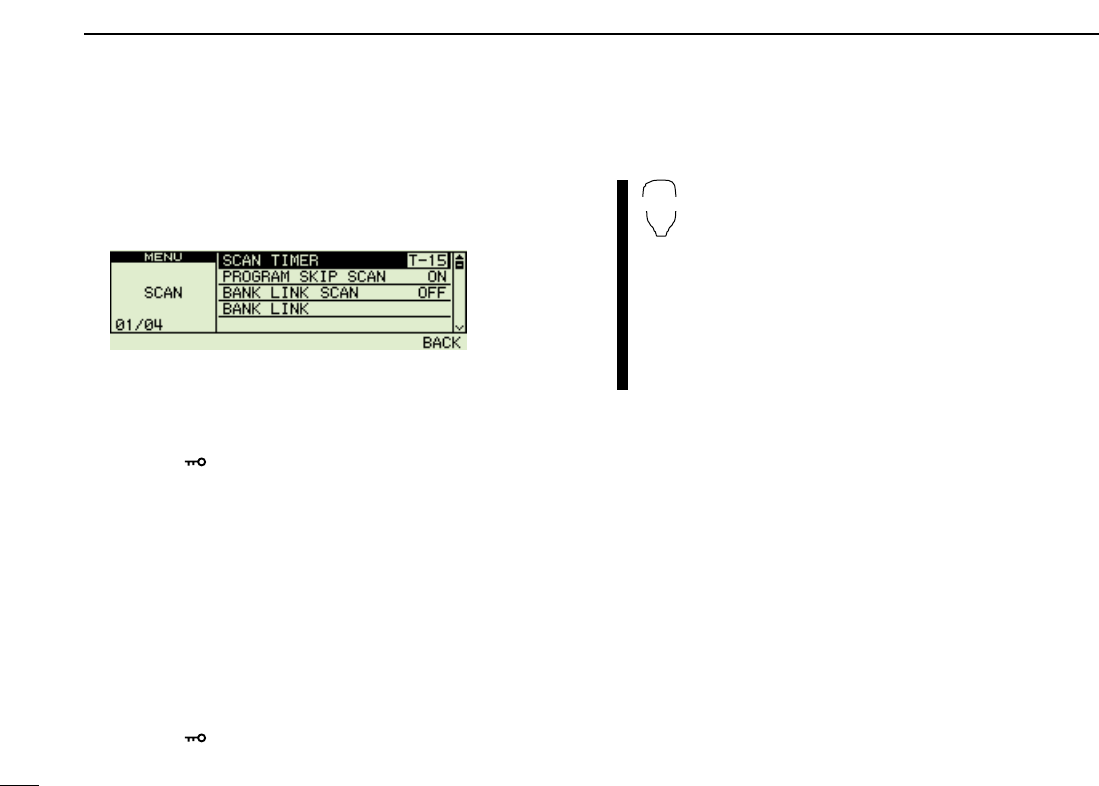
55
7SCAN OPERATION
■Scan resume condition
The scan resume condition can be selected as timer or
pause scan. The selected resume condition is also used for
priority watch. (p. ??)
qPush
[MAIN•
BAND
]
to select the desired band (left or
right) as the main band.
wPush [FF•]to display the function guide.
ePush [V/MHz•SCAN] (Right band’s) to enter MENU
screen.
eRotate the [DIAL] to select the “SCAN”mode, then push
[MAIN•BAND].
rRotate the [DIAL] to select the “SCAN TIMER”, then push
[MAIN•BAND].
rRotate the [DIAL] to set the desired timer:
•“T-5”: Scan pauses 5 sec. while receiving a signal.
•“T-10”: Scan pauses 10 sec. while receiving a signal.
•“T-15”: Scan pauses 15 sec. while receiving a signal.
•“P-2”: Scan pauses until the signal disappears and then re-
sumes 2 sec. later.
tPush [FF•]to exit MENU mode.
zPush [BAND] to select the desired band (left or
right) as the main band.
xPush [
SET
B(D-OFF)] to enter set mode.
cPush [
SET
B(D-OFF)] or [
ENT
C(T-OFF)] several
times until “SCt” or “SCP” appears as shown at
left.
vPush [Y] or [Z] to select the scan resume condi-
tion.
•See item rat left for scan resume condition details.
bPush [
CLR
A(MW)] to exit set mode.
SET
B
The display shows that the scan will resume 15
sec. after it stops.
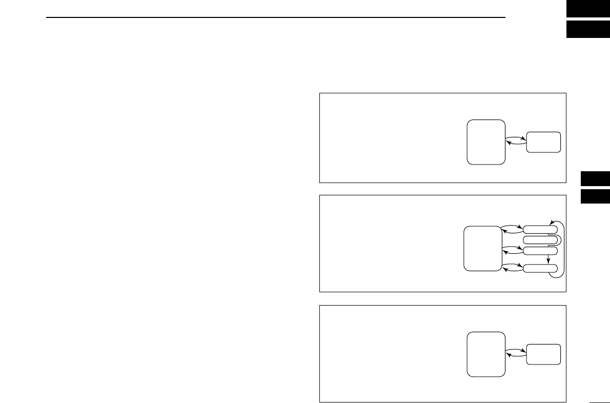
56
8
PRIORITY WATCH
1
2
3
4
5
6
7
8
9
10
11
12
13
14
15
16
17
18
19
■Priority watch types
Priority watch checks for signals on a VFO frequency every
5 sec. while operating in memory mode. The transceiver has
3 priority watch types to suit your needs. You can also trans-
mit on the VFO frequency while the priority watch operates.
The watch resumes according to the selected scan resume
condition. See previous page for details.
☞NOTES:
➧If the pocket beep function is activated, the transceiver
automatically selects the tone squelch function when pri-
ority watch starts.
MEMORY CHANNEL WATCH
While operating on a VFO fre-
quency, priority watch checks for
a signal on the selected memory
channel every 5 sec.
MEMORY SCAN WATCH
While operating on a VFO fre-
quency, priority watch checks for
signals on each memory chan-
nel in sequence.
•The memory skip function is useful
to speed up the scan.
CALL CHANNEL WATCH
While operating on a VFO fre-
quency, priority watch checks for
signals on the call channel every
5 sec.
5 sec.
VFO
frequency
50 msec.
Memory
channel
5 sec. 50 msec.
VFO
frequency
SKIP
Mch 1
Mch 2
Mch 3
Mch 199
5 sec.
VFO
frequency
50 msec.
Call
channel

57
8PRIORITY WATCH
■Priority watch operation
qSelect VFO mode; then, set an operating frequency in the
desired MAIN band (left or right).
wSet the watching channel(s).
For memory channel watch:
Select the desired memory channel.
For memory scan watch:
Select memory mode; then, push the same band’s
[V/MHz•SCAN] for 1 sec. to start memory scan.
For call channel watch:
Select the desired call channel by pushing the same
band’s [M/CALL•MW] once or twice, then rotate the
[DIAL].
ePush and hold [LOW•PRIO] for 1 sec. to start the watch.
•The transceiver checks the memory or call channel every 5 sec.
•The watch resumes according to the selected scan resume con-
dition. (p. ??)
rPush and hold [LOW•PRIO] for 1 sec. to stop the watch.
zSelect VFO mode; then, set the desired fre-
quency.
xSet the watching channel(s).
For memory channel watch:
Push [MR/CALL] then [Y] or [Z] to select the de-
sired memory channel.
For memory scan watch:
Push [MR/CALL], then push [
SCAN
2] to start the
memory scan.
For call channel watch:
Push [MR/CALL] for 1 sec. then push [Y] or [Z]
to select the call channel.
cPush [
PRIO
3(PTT-M)] to start the watch.
•The transceiver checks the memory or call channel
every 5 sec.
•The watch resumes according to the selected scan re-
sume condition. (p. 45)
•To resume the watch manually when paused, push
[
PRIO
3(PTT-M)] or [
CLR
A(MW)].
vTo stop the watch, push [
CLR
A(MW)] once (or
twice while watch is paused).
PRIO
3
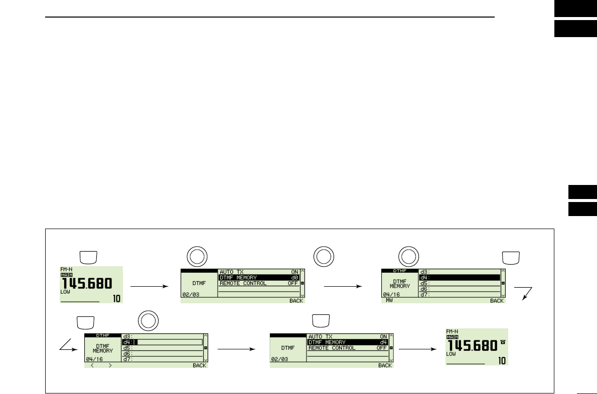
58
9
DTMF MEMORY ENCODER
1
2
3
4
5
6
7
8
9
10
11
12
13
14
15
16
17
18
19
■Programming a DTMF code
DTMF tones are used for autopatching, controlling other
equipment, etc. The transceiver has 16 DTMF memory chan-
nels (d0–d#) for storage of often-used DTMF codes of up to
24 digits.
qPush [TONE•DTMF] for 1 sec..
•Select the main band in advance, by pushing the desired band’s
[MAIN•BAND], if necessary.
wRotate [DIAL] to select the “AUTO TX”, then push
[MAIN•BAND].
eRotate the [DIAL] to select the ON, then push
[MAIN•BAND].
•“1” appears in place of the main band’s display.
rRotate the [DIAL] to select the “DTMF memory”.
tPush [MAIN•BAND] to enter the DTMF memory program-
ming condition.
•Rotate [DIAL] to select the desired DTMF channel.
yPush [V/MHz•SCAN] (left band)
.
uRotate the [DIAL] to select the desired code.
iPush [M/CALL•MW] (left band)
to select the next digit.
•Pushing [V/MHz•SCAN] (left band) move the cursor backward.
oRepeat the steps tand yto set the desired DTMF tone
sequence.
!0 Push [V/MHz•SCAN] (Right band’s) twice
to exit DTMF
memory programming condition.
[EXAMPLE]: Programming “5428AB453” into DTMF memory channel “d4.”
Push Push
RotatePush for 1 sec.
TONE
DTMF
B
A
N
D
M
A
I
N
B
A
N
D
M
A
I
N
Rotate
B
A
N
D
M
A
I
N
B
A
N
D
M
A
I
N
Push (Right band's) twice to back.
Push then rotate
V/MHz
SCAN
Repeat the previous step until
the desired code is entered.
M/CALL
MW
V/MHz
SCAN
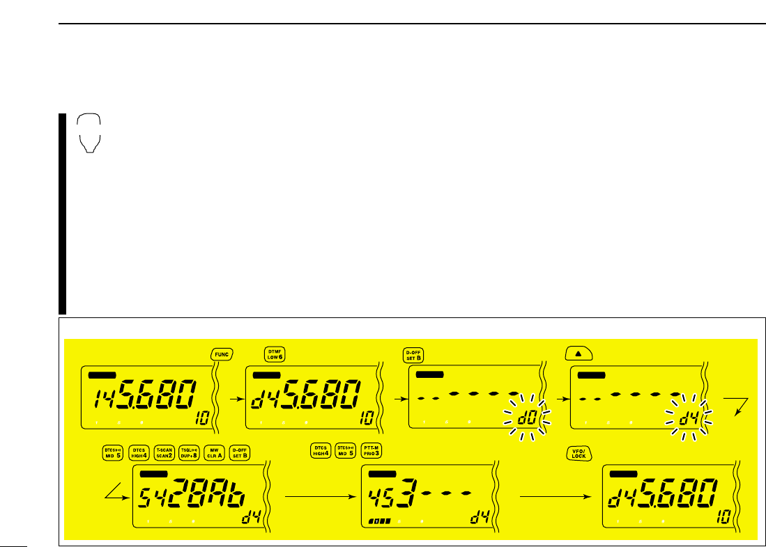
59
9DTMF MEMORY ENCODER
D
Programming a DTMF code— via microphone
zPush [FUNC] then [
LOW
6(DTMF)] to turn the
DTMF encoder ON.
•
“d” appears in place of the main band’s 100 MHz digit.
xPush [
SET
B(D-OFF)] to enter the DTMF memory
programming condition.
cPush [Y] or [Z] to select the desired DTMF
memory channel.
vPush the desired digit keys.
•When the first digit is input, previous memory contents
are cleared automatically.
•“E” stands for “MM” and “F” stands for “# .”
•Push [Y]/[Z] and repeat this step if you make a mistake.
•The S/RF indicator shows the digit group. The indication
increases every 6 digits.
bPush [VFO/LOCK] to exit the programming condition.
•The [
CLR
A(MW)] key cannot be used to exit. If pushed, code “A”
is input. Reprogram in such a case.
DTMF
[EXAMPLE]: Programming “5428AB453” into DTMF memory channel “d4.”
MAIN
T X
M
MAIN
T X
M
MAIN
T X
M
MAIN
T X
M
MAIN
T X
M
MAIN
T X
M
MAIN
T X
M
Push
Push Push
Push
Push then .
60
9
DTMF MEMORY ENCODER
1
2
3
4
5
6
7
8
9
10
11
12
13
14
15
16
17
18
19
■Transmitting a DTMF code
DAutomatic transmission (DTMF memory)
qPush and hold [TONE•DTMF] for 1 sec. to turn the
“AUTO
TX”
ON.
• “1” appears in place of the main band’s display.
wRotate [DIAL] to select the
“
DTMF MEMORY,
”
then push
[MAIN•BAND] to enter DTMF memory programming con-
dition.
eRotate [DIAL] to select the desired DTMF memory channel
then push [MAIN•BAND].
rPush [V/MHz•SCAN] (Right band’s) to return VFO mode.
t
Push [PTT] to transmit the selected DTMF memory content.
yPush and hold [TONE•DTMF] for 1 sec. , then turn the
“AUTO TX”
OFF to cancel the DTMF encoder.
•When the DTMF encoder is turned ON continuously, each push
of the PTT transmits the previously selected DTMF code.
zPush [FUNC] then [
LOW
6(DTMF)] to turn the
DTMF memory encoder ON.
•
“d” appears in place of the main band’s 100 MHz digit.
xPush [
SET
B(D-OFF)] to enter the DTMF memory
programming condition.
cPush [Y] or [Z] to select the desired channel.
vPush [PTT] to transmit the selected memory.
•Exit the programming condition automatically.
•Each push of [PTT] transmits the DTMF code.
bPush [FUNC] then [
SET
B(D-OFF)] to cancel the
DTMF memory encoder.
•When the DTMF encoder is turned ON continuously,
each push of the PTT transmits the previously se-
lected DTMF code.
DTransmitting a DTMF memory directly
zPush [FUNC] then [
LOW
6(DTMF)] to turn the
DTMF memory encoder ON.
•
“d” appears in place of the main band’s 100 MHz digit.
x
Push [DTMF-S] to turn the DTMF memory di-
rect selection ON.
•The function indicator (microphone) lights green.
cPush the desired DTMF channel.
•“0” to “9” and “A” to “D” are available for DTMF
memory channels.
•The selected DTMF code is automatically transmit-
ted without pushing PTT.
NOTE: When no DTMF code programmed chan-
nel number is pushed, it transmits the relative
DTMF code as the manual transmission de-
scribed in the next page.
vPush [DTMF-S] again to deactivate the DTMF
memory direct selection.
bPush [FUNC] then [
SET
B(D-OFF)] to cancel
the DTMF memory encoder.
DTMF-S
DTMF
61
9DTMF MEMORY ENCODER
DManual transmission
zDeactivate the DTMF memory encoder by
pushing [FUNC] then [
SET
B(D-OFF)].
x
Push [DTMF-S] to turn the DTMF direct selec-
tion ON.
•The function indicator (microphone) lights green.
cPush one of “0” to “9” and “A” to “F” keys mo-
mentarily, then push the desired DTMF keys,
0–9 and A to F.
•A: [
CLR
A(MW)] B: [
SET
B(D-OFF)],
C: [
ENT
C(T-OFF)] D: [
SQL
YD(MUTE)],
E: [MM(TONE-1)] F: [
SQL
Z#(16KEY-L)]
•Automatically transmits without pushing PTT.
•The first code, one of “A” to “F,” is not transmitted.
DTMF code transmission starts from the 2nd code.
vPush [DTMF-S] again to deactivate the DTMF
direct selection.
■DTMF speed
The rate at which DTMF memories send individual DTMF
characters can be set to accommodate operating needs.
qPush [FF•]to display the function guide.
wPush [V/MHz•SCAN] (Right band’s) to enter MENU
screen.
eRotate [DIAL] to select “DUP/TONE,” then push [MAIN
BAND].
rRotate [DIAL] to select “DTMF SPEED,” then push [MAIN
BAND].
tRotate the main band’s [DIAL] to select the desired speed
as shown in the table below, then push [MAIN BAND].
yPush [FF•]to exit MENU screen.
cps=characters/sec
DTMF-S
DISPLAY INTERVAL SPEED
100 100 msec. 5.0 cps
200 200 msec. 2.5 cps
300 300 msec. 1.6 cps
500 500 msec. 1.0 cps

62
10
TONE SQUELCH AND POCKET BEEP
1
2
3
4
5
6
7
8
9
10
11
12
13
14
15
16
17
18
19
■Tone frequency and DTCS
code
DSubaudible (repeater) tone
Some repeaters require subaudible tones to be accessed.
Subaudible tones are superimposed over your normal signal
and must be set in advance. (P ??)
DTone, DTCS, Digital code and Digital call
sign squelches
The tone squelch (CTCSS), DTCS squelch, digital code
squelch or digital call sign squelch opens only when receiving
a signal containing a matching subaudible tone, DTCS code,
Digital code or Digital call sign squelch respectively. You can
silently wait for calls from group members using the same
tone or code. Separate tone frequencies can be set for re-
peater and tone squelch/pocket beep operation.
DPocket beep
These functions use subaudible tones or DTCS codes for
calling and can be used as a “common pager” to inform you
that someone has called while you were away from the trans-
ceiver.
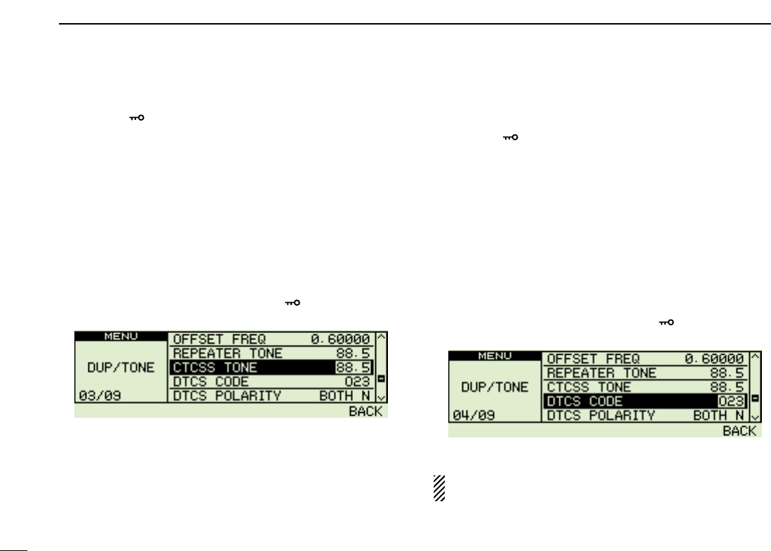
63
10 DTMF MEMORY ENCODER
D
Setting tone squelch
qPush [FF•]to display the function guide.
wPush [V/MHz•SCAN] (Right band’s) to enter MENU
screen, then rotate main band’s [DIAL] to select
“DUP/TONE” set mode.
ePush [MAIN•BAND], then rotate [DIAL] to select “CTCSS
TONE.”
rPush [MAIN•BAND], then rotate [DIAL] to select the de-
sired CTCSS tone frequency.
•Each operating band and each memory channel have indepen-
dent settings.
•See page ?? for available tone frequencies table.
tPush [V/MHz•SCAN] (Right band’s) to return to
“DUP/TONE” set mode, or push [FF•]to return to fre-
quency indication.
DSetting DTCS code for DTCS squelch or
beep
qPush [FF•]to display the function guide.
wPush [V/MHz•SCAN] (Right band’s) to enter MENU
screen, then rotate main band’s [DIAL] to select
“DUP/TONE” set mode.
ePush [MAIN•BAND], then rotate [DIAL] to select “DTCS
CODE.”
rPush [MAIN•BAND], then rotate [DIAL] to select the de-
sired DTCS code.
•Each operating band and each memory channel have indepen-
dent settings.
•See page ?? for available DTCS code table.
tPush [V/MHz•SCAN] (Right band’s) to return to
“DUP/TONE” set mode, or push [FF•]to return to fre-
quency indication.
DTCS mode can be selected in “DTCS POLARITY” menu.
(p. ??)
DTCS code setting
Tone squelch frequency setting
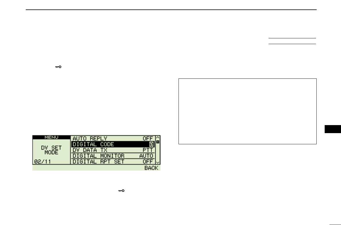
64
10
DTMF MEMORY ENCODER
1
2
3
4
5
6
7
8
9
10
11
12
13
14
15
16
17
18
19
D
Setting digital code
for digital code squelch
or beep
qPush [FF•]to display the function guide, push the left
band’s [V/MHz•SCAN] (Right band’s) several times to se-
lect DV mode.
wPush [V/MHz•SCAN] to enter MENU screen, then rotate
main band’s [DIAL] to select “DV SET MODE.”
ePush [MAIN•BAND], then rotate [DIAL] to select “DIGI-
TAL CODE.”
rPush [MAIN•BAND], then rotate [DIAL] to select the de-
sired digital code. (0-99)
•Each operating band and each memory channel have indepen-
dent settings.
tPush [V/MHz•SCAN] (Right band’s) to return to
“DUP/TONE” set mode, or push [FF•]to return to fre-
quency indication.
DSetting the YOUR and MY call signs for
digital call sign squelch or beep
See page ?? for DV MODE OPERATION.
CAUTION!: Use digital code squelch when operating with
more than 3 stations. Because the digital call sign squelch
function recognizes “MY CALL SIGN,” the digital call sign
squelch function can be used when operating with only one
station.
NOTE:
• The tone/DTCS code squelch opens sometimes when
other stations communicate with adjacent tone frequency
or DTCS code.
Digital code setting
■Digital code and digital call sign setting
The optional UT-123
65
10 DTMF MEMORY ENCODER
NOTE: The DTCS squelch operation on sub band will not
be performed during DTCS transmission, due to the same
encoder/decoder circuit is used for both main and sub
bands. And the tone squelch operation on sub band may
not be performed correctly during DTCS transmission.
■Tone/DTCS squelch operation
The tone or DTCS squelch opens only when receiving a sig-
nal with the same pre-programmed subaudible tone or DTCS
code, respectively.
qSet the operating frequency in the main band.
wProgram the CTCSS tone frequency or DTCS code in
“DUP/TONE” set mode.
•See p. ?? for programming details.
ePush [TONE•DTMF] several times until “T SQL” or “DTCS”
appears in the main band’s display.
rWhen a signal with the matched tone is received, the
squelch opens and the signal can be heard.
•When the received signal includes an unmatched tone, the
squelch does not open. However, the S/RF indicator shows the
received signal strength.
•To open the squelch manually, push and hold [DUP•MONI].
tOperate the transceiver in the normal way (push [PTT] to
transmit; release [PTT] to receive).
yTo cancel the tone squelch, push [TONE•DTMF] several
times until “T SQL” or “DTCS” disappears.
zSet the operating frequency.
xProgram the CTCSS tone frequency or DTCS
code in set mode.
•See p. 53 for programming details.
c
Push [FUNC] then [
SIMP
9(TSQL)] or [
HIGH
4(DTCS)]
to turn the tone squelch or DTCS squelch ON.
vWhen a signal with the matched tone is re-
ceived, the squelch opens and the signal can be
heard.
•When the received signal includes an unmatched
tone, the squelch does not open. However, the S/RF
indicator shows the received signal strength.
•To open the squelch manually, push [
MONI
1(BANK)].
bOperate the transceiver in the normal way (push
[PTT] to transmit; release [PTT] to receive.
nTo cancel the tone squelch, push [FUNC] then
[
ENT
C(T-OFF)].
•“T SQL” or “DTCS” disappears
TSQL
DTCS

66
10
DTMF MEMORY ENCODER
1
2
3
4
5
6
7
8
9
10
11
12
13
14
15
16
17
18
19
■Digital code/digital call sign
squelch
qSet the desired operating frequency on DV mode, Digital
code and MY CALL SIGN.
wPush [TONE•DTMF] several times to activate the digital
code or digital call sign squelch. (DSQL or CSQL)
•Digital call sign squelch “DSQL,” Digital call sign beep “DSQL
”, Digital code squelch “CSQL,” Digital code beep “CSQL ” and
no tone operation are activated in order.
eOperate the transceiver in the normal way.
rWhen the received signal includes a matching call
sign/code, the squelch opens and the signal can be heard.
•When the received signal’s call sign/code does not match, digital
call sign/digital code squelch does not open, however, the MUTE
indicator shows signal strength.
■Pocket beep operation
qSet the desired operating frequency and the desired oper-
ating mode.
wSet the desired CTCSS tone, DTCS code, Digital call sign
or Digital code.
ePush [TONE•DTMF] several times to select “T SQL ” or
“DTCS ” appears.
•When DV mode operation, push [TONE•DTMF] several times
to select “DSQL ” or “CSQL ” appears.
rWhen a signal with the correct tone, code, digital call sign
or digital code is received, the transceiver emits beep tones
for 30 sec. and blinks “.”
tPush [PTT] to answer or push [MAIN•BAND] to stop the
beeps and blinking.
Pocket beep DTCS beep
Digital call sign pocket beep Digital code pocket beep
Digital call sign pocket beep Digital code pocket beep
Digital call sign squelch Digital code squelch
The optional UT-123
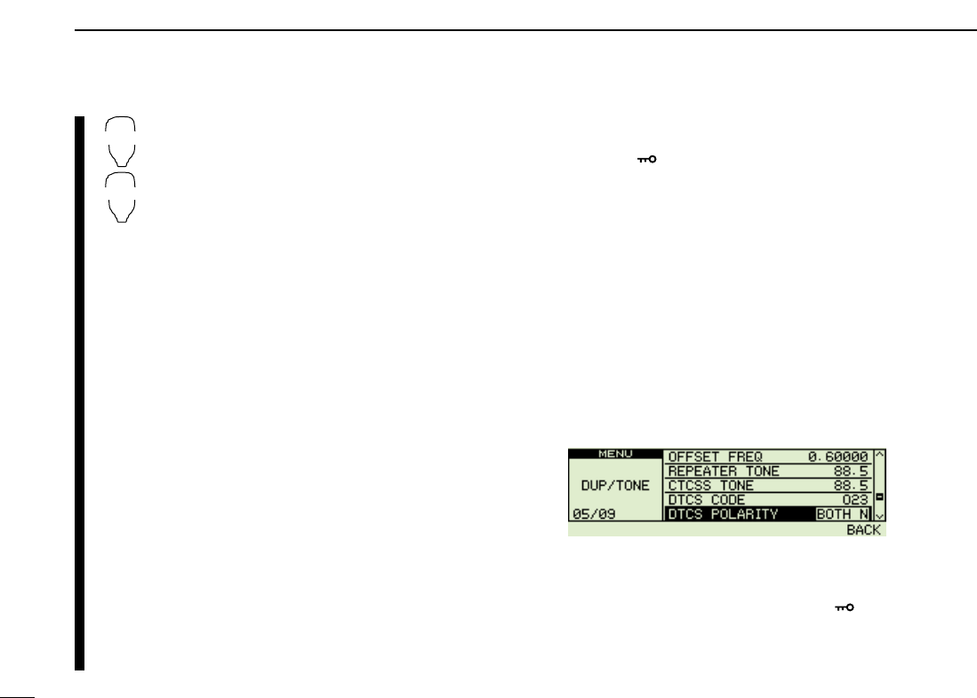
67
10 DTMF MEMORY ENCODER
zSet the operating frequency.
xProgram the CTCSS tone frequency or DTCS
code in set mode.
➥Push [
SET
B(D-OFF)] to enter set mode.
➥Push [
SET
B(D-OFF)] or [
ENT
C(T-OFF)]
several times until “Ct” for tone squelch or
“dt” for DTCS squelch appears.
•“T SQL” blinks when tone squelch (“Ct”), or
“DTCS” blinks when DTCS squelch (“dt”) is se-
lected.
➥Push [Y]/[Z] to select the desired tone fre-
quency or DTCS code.
➥Push [
SET
B(D-OFF)] to select “dtP” then
push [Y]/[Z] to select the DTCS polarity.
➥Push [
CLR
A(MW)] to exit set mode.
cPush [FUNC] then push [
DUP
+ 8(TSQLS)]
or [
MID
5(DTCSS)] to turn ON the pocket
beep with tone squelch or DTCS squelch, re-
spectively.
vWhen a signal with the matched tone is re-
ceived, the transceiver emits beep tones for
30 sec. and blinks “S.”
bPush [PTT] to answer or push [
CLR
A(MW)] to
stop the beeps and blinking.
•“S” disappears and cancels the pocket beep
function automatically.
nTo cancel the tone squelch or DTCS squelch
function, push [FUNC] then [
ENT
C(T-OFF)].
•“T SQL” or “DTCS” disappears
■DTCS polarity setting
qPush [FF•]to display the function guide.
wPush [V/MHz•SCAN] (Right band’s) to enter MENU
screen, then rotate main band’s [DIAL] to select
“DUP/TONE” set mode.
ePush [MAIN•BAND], then rotate [DIAL] to select “DTCS
POLARITY.”
rPush [MAIN•BAND], rotate [DIAL] to select the desired
DTCS polarity mode.
• BOTH N: Normal phase is used for both TX and RX.
(Default)
• TN-RR : Normal phase is used for TX; Reverse phase
for RX.
• TR-RN : Reverse phase is used for TX; Normal phase
for RX.
• BOTH R: Reverse phase is used for both TX and RX.
tPush [V/MHz•SCAN] (Right band’s) to return to
“DUP/TONE” set mode, or push [FF•]to return to fre-
quency indication.
DTCS polarity setting
TSQLS
DTCSS
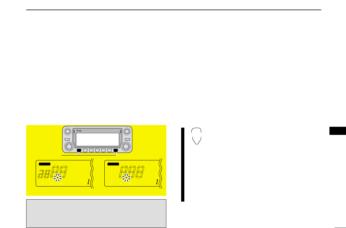
68
10
DTMF MEMORY ENCODER
1
2
3
4
5
6
7
8
9
10
11
12
13
14
15
16
17
18
19
■Tone scan
By monitoring a signal that is being operated with pocket
beep, tone or DTCS squelch function, you can determine the
tone frequency or DTCS code necessary to open a squ elch.
qSet the desired operating frequency or memory channel to
be checked for a tone frequency or code in the main band.
wPush [TONE•DTMF] several times to select the tone type,
tone squelch or DTCS, to be scanned.
•Either “T SQL” or “DTCS” appears
ePush the main band’s [V/MHz•SCAN] for 1 sec. to start
the tone scan.
•To change the scanning direction, rotate [DIAL].
rWhen the CTCSS tone frequency or 3-digit DTCS code is
matched, the squelch opens and the tone frequency is
temporarily programmed into the selected condition such
as memory or call channel.
•The tone scan pauses when a CTCSS tone frequency or 3-digit
DTCS code is detected.
•The decoded CTCSS tone frequency or 3-digit DTCS code is
used for the tone encoder or tone encoder/decoder depending
on the selected tone condition or type in step w.
-“T SQL” : CTCSS tone encoder/decoder
-“DTCS” : DTCS tone encoder/decoder
tPush [V/MHz•SCAN] to stop the scan.
zSet the frequency or memory channel to be
checked for a tone frequency.
xSelects the tone type to be scanned.
•Push [FUNC] then push; [
SIMP
9(TSQL)] for tone
squelch; [
HIGH
4(DTCS)] for DTCS squelch.
cPush [FUNC] then [
SCAN
2(T-SCAN)] to start
the tone scan.
vWhen the tone frequency is matched, the
squelch opens and the tone frequency is pro-
grammed into the selected mode such as
memory or call channel.
bPush [
CLR
A(MW)] to stop the scan.
T-SCAN
DUO BAND TRANSCEIVER i2820
MAIN
T X
T SQL
M
MAIN
T X
DTCS
M
During CTCSS frequency scan During DTCS code scan
[V/MHz•SCAN]
☞NOTE: The decoded tone frequency is programmed tem-
porarily when a memory or call channel is selected. How-
ever, this will be cleared when the memory/call channel is
re-selected.
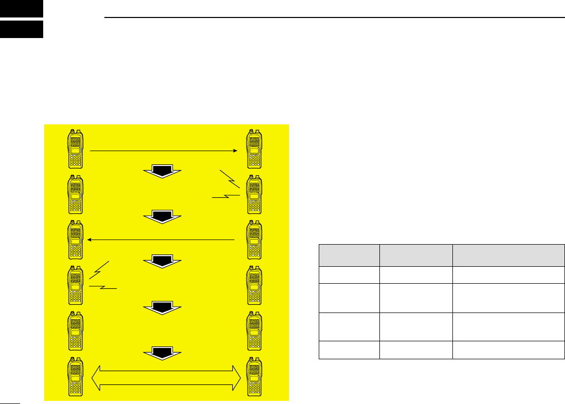
69
PAGER/CODE SQUELCH
11
■Pager function
This function uses DTMF codes for paging and can be used
as a “message pager” to confirm you of a caller’s identification
even when you leave the transceiver temporarily unattended.
■
Code programming
DDBefore programming
The pager and code squelch functions require ID codes and a
group code. These codes are 3-digit DTMF codes and must
be written into the code channels before operation.
qDecide the ID code of each transceiver and a group code
for your group.
wDecide whether you want to return to normal operation or
code squelch operation after a connection is made.
eProgram the ID code, group code and transmit codes
(other station’s codes) as below.
DDCode channel assignment
*
Channel CP automatically memorizes an ID code when receiving a
pager call. The contents in channel CP cannot be changed manually.
Pager selective code (push [PTT])
Beep Beep
Beep
Answer back (manual)
Beep Beep
Beep
Set both transceivers to either
code squelch or non-coded operation
Communication
ID OR CODE CHANNEL “RECEIVE ACCEPT” OR
GROUP CODE NUMBER “RECEIVE INHIBIT”
Your ID code
Other parties’
ID code
Group code
Memory space*
0
1–6
One of 1–6
P
“Receive accept” only
“Receive inhibit” should be
programmed in each channel.
“Receive accept” must be
programmed in one channel.
“Receive inhibit” only.
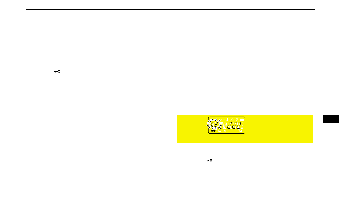
70
11
PAGER/CODE SQUELCH
1
2
3
4
5
6
7
8
9
10
11
12
13
14
15
16
17
18
19
DDCode programming
Your ID code MUST be programmed into code channel C0.
Up to 6 transmit codes (codes that you transmit) are pro-
grammable into code channels, C1 to C5, if required.
qPush [FF•]to display the function guide.
wPush [V/MHz•SCAN] (Right band’s) to enter MENU
screen.
•Rotate [DIAL] to select “DUP/TONE”, then push the main band’s
[MAIN•BAND].
eRotate [DIAL] to select “PGR CODE”, then push the
[MAIN•BAND].
rRotate [DIAL] to select code channel C0.
•“C0” is your ID code and “C1” to “C5” are transmit codes.
•Each transceiver should have a different ID code.
tPush the [MAIN•BAND], then rotate [DIAL] to select the
desired 3-digit ID code (default: 000) via the keypad.
•Push [M/CALL•MW] (Left band’s) to move the cursor right; push
[V/MHz•SCAN] (Left band’s) to move the cursor left.
yRotate [DIAL] to select a transmit code channel from C1 to
C5, then push the [MAIN•BAND].
uEnter the desired 3-digit transmit code via the keypad.
•Push [M/CALL•MW] (Left band’s) to move the cursor right; push
[V/MHz•SCAN] (Left band’s) to move the cursor left.
iPush [V/MHz•SCAN] (Left band) to set the channel to “re-
ceive inhibit” or “receive accept” ON and OFF.
•When “receive inhibit” is set, “SKIP” appears.
•Code channel C0 cannot be set as “receive inhibit.”
•See the table for “receive accept” and “receive inhibit” details
(p. SKIP channel).
oRepeat steps yand ito set additional transmit code
channels, if desired.
!0 Push [FF•]to exit MENU screen.
•Receive accept/receive inhibit
➥“Receive accept” (“SKIP” indicator does not appear) ac-
cepts pager calls when the transceiver receives a signal
with a code the same as that in the code channel.
➥“Receive inhibit” (“SKIP” indicator appears) ignores calls
even when the transceiver receives a code the same as
that in the code channel. Transmit codes should therefore
be programmed for “receive inhibit,” otherwise the trans-
ceiver will not reject unnecessary calls.

71
11 PAGER/CODE SQUELCH
■Pager operation
DCalling a specific station
qProgram the pager code channel in advance (p. 39).
wSet the operating frequency.
•
Set the volume and squelch to the desired level as in normal op-
eration.
qPush [FF•]to display the function guide, then enter the
MENU screen.
ePush [MAIN•BAND] to select “DUP/TONE”, then select
the “PGR/C-SQL”.
eRotate [DIAL] to set the “PGR”, then push [MAIN•BAND].
•“PGR” indicator appear in normal frequency mode.
rSelect the desired 3-digit transmit code channel:
➥Enter “PGR CODE” (the pager code selection mode)
in “DUP/TONE” set mode.
➥Rotate [DIAL] to select the desired pager code chan-
nel.
➥Push [FF•]to return to previous mode.
tPush [PTT] to transmit the pager code.
yWait for an answer back.
•When the transceiver receives an answer back code, the func-
tion display shows the other member’s ID or group code.
uAfter confirming a connection, push [MAIN•BAND] to enter
the “PGR/C-SQL” set mode, then rotate [DIAL] to select
the code squelch operation “C-SQL,” or non-selective
calling system “OFF.”
•DO NOT push any digit keys while code channels C0 to C5 are
displayed, otherwise code channel contents will be changed.
iCommunicate with the other party as normal: push [PTT]
to transmit; release to receive.
DWaiting for a call from a specific station
qSet the operating frequency.
wEnter “PGR/C-SQL” set item in “DUP/TONE” set mode.
➥Rotate [DIAL] to select “PGR” if “C-SQL” or “OFF” ap-
pears.
➥Push [FF•]to return to previous mode.
•“PGR” indication appear.
eWait for a call.
•When receiving a call, the caller’s ID or group code appears as
shown at next page.
•DO NOT push any digit keys while code channels C0 to C5 are
displayed, otherwise code channel contents will be changed.
rPush [PTT] to send an answer back call and display the
operating frequency.
tAfter confirming a connection, enter “PGR/C-SQL” set
item, then rotate [DIAL] to select the code squelch
operation “C-SQL,” or non-selective calling system “OFF.”
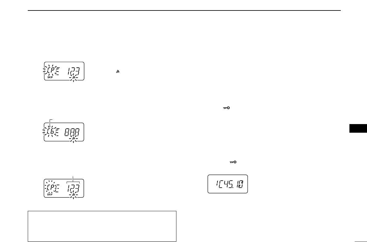
72
11
PAGER/CODE SQUELCH
1
2
3
4
5
6
7
8
9
10
11
12
13
14
15
16
17
18
19
•PERSONAL CALLS
This display appears when you are called with your ID code
and the calling station’s ID code is 123.
•GROUP CALLS
This display appears when you are called with the group
code, 888, and 888 has been programmed into code channel
C5.
•ERROR INFORMATION
When the transceiver receives an incomplete code, “E” and
previously received code appear.
■Code squelch
When using code squelch you will only receive calls from sta-
tions which know your ID or group code. A 3-digit code is sent
each time [PTT] is pushed in order to open the receiving sta-
tion’s code squelch prior to voice transmission.
qSet the operating frequency.
• Set the volume and squelch to the desired level as in normal op-
eration.
wPush [FF•]to display the function guide.
wEnter “PGR/C-SQL” set item in “DUP/TONE” set mode,
then push [MAIN•BAND].
• Rotate [DIAL] to select “C-SQL,” if “PGR” or “OFF” appears.
wEnter “PGR CODE” set item in “DUP/TONE” set mode,
then push [MAIN•BAND].
eSelect the desired transmit code channel:
➥Rotate [DIAL] to select the desired code channel.
➥Push [FF•]to return to previous mode.
•“C-SQL.” indication apper.
rOperate the transceiver in the normal way (push [PTT] to
transmit; release [PTT] to receive).
tTo cancel the code squelch, Enter “PGR/C-SQL” set item,
then rotate [DIAL] to select “OFF”
•100 MHz digit shows “1” when the function is cancelled.
Previously received code.
Code channel
“CP” and “ ” blink.
During channel number indication (described on page 16)
To use these functions in channel number indication, the
pager/code squelch setting must be programmed with other
memory contents before selecting channel number indication.

73
EXTERNAL DTMF REMOTE
12
External DTMF remore function can be remotely controlled
using DTMF signals on the sub band. To operate external
DTMF remote, a 144MHz or 430(440) MHz transceiver with a
DTMF encoder is required.
qSet the sub band frequency to receive a control signal
(DTMF code).
• The optional tone squelch function can be used for the sub band
to increase remote control reliability.(p. Tone squelch)
wEnter “DUP/TONE”into MENU screen.
eProgram a 3-digit password into “PGR CODE” the sub
band’s code channel 5, if desired.(p. ??)
• The initial value of code channel 5 is “000 (default); receive ac-
cept.” If you do not require the password, set the channel as “re-
ceive inhibit.”
rSelect the main band by pushing a tuning dial, then set the
desired frequency for operation.
tPush and hold [TONE•DTMF], then rotate [DIAL] to select
“REMOTE CONTROL”turn ON appears to select standby for
the remote control.
yPush [MAIN•BAND], then rotate [DIAL] to select ON
• “” indicator appear
uSet the operating frequency of the controller transceiver
equal to the sub band frequency of the IC-2820H.
• Make sure a tone frequency is set when using the optional tone
squelch function with the IC-2820H.
• The external DTMF remote does not accept a control signal on
the main band frequency.
iFrom the controller transceiver, transmit the DTMF code
as follows:
oTo cancel standby for the remote control, push and hold
[TONE•DTMF].
• “” disappears.
• Pushing [FUNC] then [
SET
B(D-OFF)] also cancels standby for
the remote control.
• • • •
Password
(if programmed)
Command
(See example at right)
B# B✽
(or F) (or E)
74
12
EXTERNAL DTMF REMOTE
1
2
3
4
5
6
7
8
9
10
11
12
13
14
15
16
17
18
19
144.750 MHz
Memory channel 15
Scratch pad
memory 2
Password
(if programmed)
Frequency setting
2 digits
(or F) VFO
mode
[ENT] (UP) (or E)
B 1 2 3 # 3 D
Call
channel
[DOWN] [DOWN]
1
1 4
VFO
mode
[ENT]
2 D 1 5
580
VFO
mode
[ENT] 100
MHz
100
kHz
10
kHz
10
MHz
1 MHz
3 D 14475
#B
DTMF KEYPAD
[EXAMPLE]: Setting the opetating frequency to 145.8125 MHz (when the VHF tuning step is 12.5 kHz).
1 2 3 A
4 5 6 B
7 8 9 C
0 # D
CALL
DOWN
MR VFO
HIGH
LOW1
UP ENT
CLR
[EXAMPLE]
Note for the [ENT] key
• When the entered frequency is outside of the frequency coverage, the
input digits will be cleared.
• To adjust the frequency less than 10 kHz or to select a scan edge
memory channel (1A, 1B), use the [UP] or [DOWN] key.
75
DIGITAL MODE OPERATION (Optional UT-123 is required )
13
■Digital mode operation
The IC-91A*/91AD can be operated in digital voice mode and
low-speed data operation for both transmit and receive. It can
also be connected to a GPS receiver (compatible with an RS-
232 output/NMEA format/4800 bps) and transmit/receive position
data.
*The optional UT-121 is required for the IC-91A.
■Call sign programming
Four types of call sign memories are available; your own call
sign “MY CALL SIGN,” other station call sign “YOUR CALL
SIGN,” repeater call sign “RPT1 CALL SIGN” and “RPT2
CALL SIGN.” “MY CALL SIGN” can store up to 6 call signs,
“YOUR CALL SIGN” can store up to 60 call signs and
“RPT1/2 CALL SIGN” can store up to 60 call signs, and each
call sign can be programmed with up to 8 characters.
DDYour own call sign programming
Your own call sign must be programmed for both digital voice
and low-speed data communications (including GPS transmis-
sion).
qSelect B band as the main band. (p. 14)
wEnter “MY” in call sign set mode.
•MY CALL SIGN screen is displayed.
eRotate [DIAL]†to select the desired call sign memory,
“M01” to “M06.”
rPush [≈≈](6) to enter call sign programming mode.
•The 1st digit blinks.
tRotate [DIAL]†to select the desired character or code.
•Push [A/a](3) to change the character group from “AB” (alpha-
betical characters; capital letters), “12” (numbers) and “/” (sym-
bols) in sequence.
M01M01
†
/
MY CALL SIGN
r
:SET:SET
:SEL:SEL
:CUR:CUR
CLR:CLRCLR:CLR
A/a:CHARA/a:CHAR
AB
M01M01
/
:SET
:BACK
:SEL
:EDIT
CLR:CLR
MY CALL SIGN
r
MENU screen➪CALL SIGN➪MY
(Push [MENU/LOCK]) (Rotate [DIAL]†, then push [ï](5)†.)
Although [DIAL] and [ï](5) are used for description in this
section, [∫∫](2)/[√√](8) and [≈≈](6) are available instead of
[DIAL] and [ï](5).

76
13
DV MODE OPERATION (Optional UT-123 is required)
1
2
3
4
5
6
7
8
9
10
13
12
13
14
15
16
17
18
19
yPush [≈≈](6) to select 2nd digit, then rotate [DIAL]†to se-
lect the desired character or code.
•Push [≈≈](6) to move the cursor right; push [ΩΩ](4) to move the
cursor left.
•2nd digit blinks (1st digit stops blinking).
uRepeat the steps tand yto enter your own call sign.
•Up to a 8-digit of call sign can be set.
•If an un-necessary character is entered, push [≈≈](6) or [ΩΩ](4) to
select the character, then push [CLR](1) to erase the selected
character, or push and hold [CLR](1) for 1 sec. to erase all char-
acters following the cursor.
•When programming a note (Up to a 4-digit for operating radio
type or area, etc.), go to step i, otherwise go to step !0.
iPush [≈≈](6) several times to set the cursor beside “/” indi-
cation.
oRepeat steps tto yto program the desired 4-character
note.
!0 Push [ï](5) to store the programmed call sign with note
and returns to MY CALL SIGN screen.
!1 Push [MENU/LOCK] to return to frequency indication.
M01M01
MYCALL MYCALL
/IC91 /IC91
:SET
:BACK
:SEL
:EDIT
CLR:CLR
MY CALL SIGNMY CALL SIGN
r
M01M01
M†
/
MY CALL SIGNMY CALL SIGN
r
:SET:SET
:SEL:SEL
:CUR:CUR
CLR:CLRCLR:CLR
A/a:CHARA/a:CHAR
AB
77
13 DV MODE OPERATION (Optional UT-123 is required)
DDStation call sign programming
Station call sign must be programmed for the specified sta-
tion call as well as repeater operation in both digital voice and
low-speed data communications.
qSelect B band as the main band. (p. 14)
wEnter “UR” in call sign set mode.
•YOUR CALL SIGN screen is displayed.
eRotate [DIAL]†to select the desired call sign memory,
“U01” to “U60.”
rPush [≈≈](6) to enter call sign programming mode.
•The 1st digit blinks.
tRotate [DIAL]†to select the desired character or code.
•Push [A/a](3) to change the character group from “AB” (alpha-
betical characters; capital letters), “12” (numbers) and “/” (sym-
bols) in sequence.
yPush [≈≈](6) to select 2nd digit, then rotate [DIAL]†to se-
lect the desired character or code.
•Push [≈≈](6) to move the cursor right; push [ΩΩ](4) to move the
cursor left.
•2nd digit blinks (1st digit stops blinking).
uRepeat the steps tand yto enter the desired station call
sign.
•Up to an 8-digit of call sign can be set.
•If an un-necessary character is entered, push [≈≈](6) or [ΩΩ](4) to
select the character, then push [CLR](1) to erase the selected
character, or push and hold [CLR](1) for 1 sec. to erase all char-
acters following the cursor.
iPush [ï](5) to store the programmed call sign and returns
to YOUR CALL SIGN screen.
oPush [MENU/LOCK] to return to frequency indication.
U01U01
STATION1 STATION1
:SET
:BACK
:SEL
:EDIT
CLR:CLR
YOUR CALL SIGN
r
U01U01 AB
S†
:SET:SET
:SEL:SEL
:CUR:CUR
CLR:CLRCLR:CLR
A/a:CHARA/a:CHAR
0:CQ0:CQ
YOUR CALL SIGNYOUR CALL SIGN
r
U01U01 AB
†
:SET:SET
:SEL:SEL
:CUR:CUR
CLR:CLRCLR:CLR
A/a:CHARA/a:CHAR
0:CQ0:CQ
YOUR CALL SIGNYOUR CALL SIGN
r
U
CQCQCQ CQCQCQ
:SET
:BACK
:SEL
:EDIT
CLR:CLR
YOUR CALL SIGNYOUR CALL SIGN
r
MENU screen➪CALL SIGN➪UR
(Push [MENU/LOCK]) (Rotate [DIAL]†, then push [ï](5)†.)

78
13
DV MODE OPERATION (Optional UT-123 is required)
1
2
3
4
5
6
7
8
9
10
13
12
13
14
15
16
17
18
19
NOTE: During the call sign programming mode (rto u),
push [CQ](0) to set “CQCQCQ,” and push [CQ](0) again
to return to the previously stored call sign.
✔
For your information
The IC-91A/91AD has call sign edit record function.
When editing a call sign stored in a call sign memory, regular
memory or call channel, the default setting is to store the
edited call sign into a blank channel automatically. (“FULL” is
displayed when all call sign memory is programmed.)
The edited call sign can be over-written when the setting of
the EDIT RECORD is set to OFF or SELECT. (p. 95)
However, you must manually over-write a programmed call
sign in regular memory and call channels. (Temporary opera-
tion without over-writing is possible.)

79
13 DV MODE OPERATION (Optional UT-123 is required)
■Digital voice mode operation
qSet the desired frequency in B band. (pgs. 14, 18)
•Select output power, if desired. (p. 24)
wSelect DV mode. (p. 21)
eSet your own call sign for DV operation as follows.
zEnter “MY” in call sign set mode.
xRotate [DIAL]†to select the desired your own call sign
channel (if you have programmed several call signs) then
push [ï](5) to set the call sign and return to CALL SIGN
screen.
•See page 34 for your own call sign programming details.
rSet the desired call sign as described in “When calling the
desired station (p. 39)” or “When sending a CQ (p. 39).”
tPush and hold [PTT] to transmit and speak into the micro-
phone at normal voice level.
•Tx/Rx indicator lights red and the RF meter shows the output
power.
yRelease [PTT] to return to receive.
•The other station call sign will be received.
•Received call signs can be stored into the received call record
automatically. See page 93 for details.
NOTE: The digital mode operation is vastly different from
FM mode. One of the differences is in digital mode the
squelch does not function as in FM mode. Changing the
squelch setting will not open it to hear the hiss of “White
Noise.” It only activates for digital squelch functions such
as CSQL (Digital code squelch) or DSQL (Digital call sign
squelch).
UR:UR:
R1:R1:
R2:NOT USE*R2:NOT USE*
MY:MYCALLMY:MYCALL
/IC91 /IC91
CALL SIGN
r
MENU screen➪CALL SIGN➪MY
(Push [MENU/LOCK]) (Rotate [DIAL]†, then push [ï](5)†.)

80
13
DV MODE OPERATION (Optional UT-123 is required)
1
2
3
4
5
6
7
8
9
10
13
12
13
14
15
16
17
18
19
DDWhen calling the desired station
Continued instruction from step xon page 38.
cRotate [DIAL]†to select “UR,” then push [ï](5)†.
•YOUR CALL SIGN screen is displayed.
vRotate [DIAL]†to select the call sign channel in which de-
sired station’s call sign is programmed.
•See page 36 for station call sign programming details.
bPush [ï](5) to set the station’s call sign and return to
CALL SIGN screen.
nPush [MENU/LOCK] to return to frequency indication.
mPerform the instruction steps tand yon page 38.
DDWhen sending a CQ
Continued instruction from step xon page 38.
cRotate [DIAL]†to select “UR,” then push [ï](5)†.
•YOUR CALL SIGN screen is displayed.
vRotate [DIAL]†to select the call sign channel in which
“CQCQCQ” is programmed.
Or, select “U” then push [≈≈](6) and [CQ](0) in sequence to
set “CQCQCQ.”
bPush [ï](5) to set “CQCQCQ” as the call sign and return
to CALL SIGN screen.
nPush [MENU/LOCK] to return to frequency indication.
mPerform the instruction step tand yon page 38.
UR:CQCQCQUR:CQCQCQ
R1:R1:
R2:NOT USE*R2:NOT USE*
MY:MYCALLMY:MYCALL
/IC91 /IC91
CALL SIGN
r
UR:STATION1UR:STATION1
R1:R1:
R2:NOT USE*R2:NOT USE*
MY:MYCALLMY:MYCALL
/IC91 /IC91
CALL SIGNCALL SIGN
r
81
13 DV MODE OPERATION (Optional UT-123 is required)
■About D-STAR system
In the D-STAR system, repeater linking via a 10 GHz band
backbone and internet network (gateway connection) capa-
bilities are available. This system provides you to with much
wider coverage range during digital voice mode operation.
• D-STAR system outline
For current repeater operation, stations that are communicat-
ing must both be in the same repeater’s operating area.
However, in the D-STAR system as in the illustration at left,
the repeaters can be linked via the system repeaters (with a
10 GHz signal). Thus stations A and B can communicate even
though they are in different repeater operating areas.
Also, the D-STAR system repeaters are connectable through
the internet— gateway connection capability.
For example, when station B uses the gateway connection
station B can communicate with the station C!
By using the gateway connection, long distance communica-
tion like DX operation may be possible with 144 or 440 MHz
digital voice!
In the D-STAR system, an independent repeater’s operating
area is called an Area and a group that of linked repeaters via
a 10 GHz backbone is called a Zone.
Station
A
Station C Station D
Repeater A
Repeater D
440 MHz
440 MHz
Repeater C
10 GHz
Station
B
Repeater B
10 GHz
440 MHz
440 MHz
Internet
network
Internet
network

82
13
DV MODE OPERATION (Optional UT-123 is required)
1
2
3
4
5
6
7
8
9
10
13
12
13
14
15
16
17
18
19
■Digital repeater operation
Repeater call signs must be programmed for repeater opera-
tion in both digital voice and low-speed data communications.
DDRepeater call sign programming
qSelect B band as the main band. (p. 14)
wEnter “R1” or “R2” in call sign set mode.
•RPT1 or RPT2 CALL SIGN screen is displayed.
eRotate [DIAL]†to select the desired call sign memory,
“R01” to “R60.”
rPush [≈≈](6) to enter call sign programming mode.
•The 1st digit blinks.
tRotate [DIAL]†to select the desired character or code.
•Push [A/a](3) to change the character group from “AB” (alpha-
betical characters; capital letters), “12” (numbers) and “/” (sym-
bols) in sequence.
•Set “/” at the 1st digit then set the desired area repeater’s call
sign (in a different zone) for CQ call (“/” stands for “CQCQCQ”) in
a different zone operation. (p. 44)
yPush [≈≈](6) to select 2nd digit, then rotate [DIAL]†to se-
lect the desired character or code.
•Push [≈≈](6) to move the cursor right; push [ΩΩ](4) to move the
cursor left.
•2nd digit blinks (1st digit stops blinking).
uRepeat the steps tand yto enter the desired repeater
call sign.
•Up to an 8-digit of call sign can be set.
•Push [7] when setting with the gateway connection if the se-
lected repeater has gateway capability. (The gateway connec-
tion can be set in RPT1 only when “NOT USE✱” is set to RPT2.)
•If an un-necessary character is entered, push [≈≈](6) or [ΩΩ](4) to
select the character, then push [CLR](1) to erase the selected
character, or push and hold [CLR](1) for 1 sec. to all characters
following the cursor.
iPush [ï](5) to store the programmed call sign and returns
to RPT1 or RPT2 CALL SIGN screen.
oPush [MENU/LOCK] to return to frequency indication.
R01R01
RPT1AA G RPT1AA G
:SET
:BACK
:SEL
:EDIT
CLR:CLR
RPT1 CALL SIGN
r
MENU screen➪CALL SIGN➪R1/R2
(Push [MENU/LOCK]) (Rotate [DIAL]†, then push [ï](5)†.)

83
13 DV MODE OPERATION (Optional UT-123 is required)
DDRepeater operation in the same zone
qSet the desired repeater’s frequency, offset and shift direc-
tion in B band. (pgs. 18, 31)
•Select DV mode in advance. (p. 21)
wSet your own call sign. (p. 38)
•See p. 34 for your own call sign programming.
eSet the desired station call sign. (p. 39)
•See p. 36 for station call sign programming.
rSet the repeater’s call sign as follows;
zEnter “R1” in call sign set mode.
xRotate [DIAL]†to select the nearest repeater’s call sign.
cPush [ï](5) to set the call sign for “R1.”
•Return to CALL SIGN screen.
vRotate [DIAL]†to select “R2” then push [ï](5)†.
•RPT2 CALL SIGN screen is displayed.
bRotate [DIAL]†to select the desired repeater’s (in the
same zone) call sign.
•Select “NOT USE✱” when not operating RPT2.
nPush [ï](5) to set the call sign for “R2.”
•Return to CALL SIGN screen.
mPush [MENU/LOCK] to return to frequency indication.
tPush [PTT] to transmit; release to receive.
UR:CQCQCQUR:CQCQCQ
R1:RPT1AAR1:RPT1AA
R2:NOT USE*R2:NOT USE*
MY:MYCALLMY:MYCALL
/IC91 /IC91
CALL SIGNCALL SIGN
r
MENU screen➪CALL SIGN➪R1
(Push [MENU/LOCK]) (Rotate [DIAL]†, then push [ï](5)†.)
84
13
DV MODE OPERATION (Optional UT-123 is required)
1
2
3
4
5
6
7
8
9
10
13
12
13
14
15
16
17
18
19
Area 1
Zone
to another Zone
• Setting example 1
Repeater 1
: A11111
Area 2 Repeater 2
: A22222
Area 3
(Gateway)
Repeater 3
: A33333
Area 4 Repeater 4
: A44444
✔
What is the area?
The Area is the communication range that is
covered by a local repeater.
A Local repeater is called an area repeater in
the D-STAR system.
✔
What is the zone?
The Zone is composed of several areas, that
are linked by the 10 GHz microwave signal.
The areas 1 to 4 make up a zone in the exam-
ple above.
Station A
: A2222A Station B
: A2222B
Station C
: A4444C
Internet
network
Internet
network
❑The setting when Station A is call-
ing Station B
UR : A2222B
R1 : A22222
R2 : NOT USEQ
MY : A2222A
❑The setting when Station A is mak-
ing a CQ call in area 1
UR : CQCQCQ
R1 : A22222
R2 : A11111
MY : A2222A
❑The setting when Station A is call-
ing Station C
UR : A4444C
R1 : A22222
R2 : A44444
MY : A2222A

85
13 DV MODE OPERATION (Optional UT-123 is required)
DDRepeater operation into another zone
qSet the desired repeater’s frequency, offset and shift direc-
tion in B band. (pgs. 18, 31)
•Select DV mode in advance.
wSet your own call sign. (p. 38)
•See p. 34 for your own call sign programming.
eSet the desired station call sign. (p. 39)
• When making a CQ call
Set the desired repeater’s (in a different zone) call sign with
a “/” symbol at the 1st digit, for the area in which you
want to make a CQ call, into “UR.”
•See p. 36 for station call sign programming.
rSet the repeater’s call sign as follows;
zEnter “R1” in call sign set mode.
xRotate [DIAL]†to select the nearest repeater’s call sign.
•If the nearest repeater is gateway repeater, select the re-
peater’s call sign with “G” setting at the 8th digit.
cPush [ï](5) to set the call sign for “R1.”
•Return to CALL SIGN screen.
vRotate [DIAL]†to select “R2” then push [ï](5)†.
bRotate [DIAL]†to select the gateway repeater’s (in the
same zone) call sign.
•The call sign should have “G” setting at the 8th digit.
•When gateway repeater call sign is set in “R1,” select “NOT
USE✱” for “R2” setting.
nPush [ï](5) to set the call sign for “R2.”
•Return to CALL SIGN screen.
mPush [MENU/LOCK] to return to frequency indication.
tPush [PTT] to transmit; release to receive.
UR:CQCQCQUR:CQCQCQ
R1:RPT1AAR1:RPT1AA
R2:NOT USE*R2:NOT USE*
MY:MYCALLMY:MYCALL
/IC91 /IC91
CALL SIGN
r
MENU screen➪CALL SIGN➪R1
(Push [MENU/LOCK]) (Rotate [DIAL]†, then push [ï](5)†.)
86
13
DV MODE OPERATION (Optional UT-123 is required)
1
2
3
4
5
6
7
8
9
10
13
12
13
14
15
16
17
18
19
Area 1
Zone A
• Setting example 2
Repeater 1
: A11111
Area 2
Repeater 2
: A22222
Area 3
(Gateway)
Repeater 3
: A33333
Repeater 3 3
: A33333
Repeater 3
: A33333 Area 4
Repeater 4
: A44444
Zone B
Area 6
Repeater 6
: B66666
Area 7
(Gateway) Repeater 7
: B77777
Area 8
Repeater 8
: B88888
Area 5 Repeater 5
: B55555
Station C
: B6666C
Station A
: A2222A Station B
: A3333B
Internet
network
Internet
network
❑The setting when Station A is call-
ing Station C
UR : B6666C
R1 : A22222
R2 : A33333 G
MY : A2222A
❑The setting when Station A is mak-
ing a CQ call in area 8
UR : /B88888
R1 : A22222
R2 : A33333 G
MY : A2222A
❑The setting when Station B is call-
ing Station C
UR : B6666C
R1 : A33333 G
R2 : NOT USE✱
MY : A3333B
87
13 DV MODE OPERATION (Optional UT-123 is required)
■Received call sign
When a call is received in DV mode, the calling station and
the repeater call signs being used can be stored into the re-
ceived call record. The stored call signs are viewable in the
following manner.
Up to 20 calls can be recorded.
DDDesired call record indication
qEnter RX call sign set mode.
•RX CALL SIGN screen is displayed.
wRotate [DIAL]†to select the desired record channel.
eTo confirm the received call, push [ï](5) several times to
select the desired call sign from CALLER, CALLED,
RXRPT1 and RXRPT2.
CALLER : The station call sign that made a call.
CALLED : The station call sign called by the caller.
RXRPT1 : The repeater call sign used by the caller station.
RXRPT2 : The repeater call sign linked from RXRPT1.
rPush [MENU/LOCK] to return to frequency indication.
NOTE: When a call is received in DV mode when the
power save function is activated, the call sign may not be
received correctly.
This is normal, not a malfunction, because of header of the
call sign cannot be detected during power save.
Turn the power save function OFF (p. 115) if you want to
receive a call sign correctly even in stand-by condition.
✔
For your information
When receiving a call, the received station call sign is auto-
matically displayed and scrolled in sequence at the bottom
line of the function display.
This can be turned OFF in display set mode. (p.100)
RX01RX01
CALLER: CALLER:
AAAAAAAAAAAA
/
:CALLED :SEL
:COPY CLR:CLR
RX CALL SIGN
r
RX01RX01
CALLED: CALLED:
CQCQCQCQCQCQ
:RXRPT1 :SEL
:COPY CLR:CLR
RX CALL SIGN
r
RX01RX01
RXRPT2: RXRPT2:
:CALLER :SEL
:COPY CLR:CLR
RX CALL SIGN
r
RX01RX01
RXRPT1: RXRPT1:
:RXRPT2 :SEL
:COPY CLR:CLR
RX CALL SIGN
r
Push
• Station call sign • Called station call sign
• Repeater 1 call sign• Repeater 2 call sign
MENU screen➪RX CALL SIGN
(Push [MENU/LOCK]) (Rotate [DIAL]†, then push [ï](5)†.)
88
13
DV MODE OPERATION (Optional UT-123 is required)
1
2
3
4
5
6
7
8
9
10
13
12
13
14
15
16
17
18
19
DDOne-touch reply using the call record
The stored call signs in the call record can be used to the call.
qAfter receiving a call, push and hold [RX➝CS](CALL) for
1 sec.
Or, while pushing and holding [RX➝CS](CALL), rotate
[DIAL] to select the desired call sign record.
•Set your own call sign (MY) in advance. (p. 34)
•The call sign stored in “CALLER” is stored as “UR,” “RXRPT1” is
stored as “R2” and “RXRPT2” is stored as “R1.”
•Error beeps sound when a call sign is received incorrectly, and
no call sign is set in this case.
wPush [PTT] to transmit; release to receive.
✔
For your information
When a call specifying your call sign is received, the call signs
of the calling station and the repeater it is using can be used
for operation automatically.
•When “RX call sign auto write” (p. 93) is set to “AUTO,” the
station call sign in “CALLER” is set to “UR” automatically.
•When “Repeater call sign auto write” (p. 93) is set to “AUTO,”
the stored station call sign in “RXRPT1” is stored as “R2”
and “RXRPT2” is stored as “R1” automatically.
Important!
Setting call signs with the “One-touch reply using the call
record” operation as at left are for temporary operation only.
Therefore, the set call signs will be overwritten when an-
other call record is used to set call signs.
•Never saved into a call sign memory.
If you want to save the set call signs, see “Copying the call
record contents into call sign memory” (p. 50) for details.
DVDV
B
439706
-DUP-DUP
25
AAAAAA
The received call sign is displayed while pushing and
holding [CALL/RX➝CS] when [DIAL] is rotated while
[CALL/RX➝CS] is pushed.
89
13 DV MODE OPERATION (Optional UT-123 is required)
■Copying the call sign
DDCopying the call sign memory contents
This function is convenient when or modifying a part of the
current call sign.
NOTE: Make sure that the “EDIT RECORD” item in DV set
mode is set to “AUTO” or “SELECT” in advance. (p. 95)
qDuring DV mode operation, enter call sign set mode.
•CALL SIGN screen is displayed.
wRotate [DIAL]†to select “UR,” “R1” or “R2” as desired, then
push [ï](5)†.
eRotate [DIAL]†to select the desired call sign channel to be
copied.
•U01–U60 and R01–R60 are available.
• When “AUTO” is set to “EDIT RECORD” item
rPush [≈≈](6) to select the call sign programming mode.
•A blank channel is selected automatically.
•The 1st digit of the selected call sign blinks.
tEdit or modify the selected call sign as described in “DSta-
tion call sign programming” (p. 36) or “DRepeater call sign
programming” (p. 41).
yPush [ï](5) to store the edited/modified call sign into the
selected blank channel.
NOTE: The message “FULL” is displayed when no blank
channel is available in station or repeater call sign mem-
ory.
Select the desired call sign channel number as described
in step uof “• When “SELECT” is set to “EDIT RECORD”
item” at right-hand page in this case.
U21U21 AB
†AAAAAAAAAA
:SET:SET
:SEL:SEL
:CUR:CUR
CLR:CLRCLR:CLR
A/a:CHARA/a:CHAR
0:CQ0:CQ
YOUR CALL SIGNYOUR CALL SIGN
r
A blank channel
number blinks.
MENU screen➪CALL SIGN
(Push [MENU/LOCK]) (Rotate [DIAL]†, then push [ï](5)†.)

90
13
DV MODE OPERATION (Optional UT-123 is required)
1
2
3
4
5
6
7
8
9
10
13
12
13
14
15
16
17
18
19
• When “SELECT” is set to “EDIT RECORD” item
rPush [≈≈](6) to select the call sign programming mode.
•The 1st digit of the selected call sign blinks.
tEdit or modify the selected call sign as described in “DSta-
tion call sign programming” (p. 36) or “DRepeater call sign
programming” (p. 41).
yPush [ï](5).
• Call sign channel number blinks.
uRotate [DIAL]†to select the desired call sign channel to
store.
iPush [ï](5) to store the edited/modified call sign into the
selected channel.
U21U21 ABAB
AAAAA1 AAAAA1
:SET:SET
:SEL:SEL
:CUR:CUR
CLR:CLRCLR:CLR
A/a:CHARA/a:CHAR
0:CQ0:CQ
YOUR CALL SIGNYOUR CALL SIGN
r
Call sign channel
number bliks.

91
13 DV MODE OPERATION (Optional UT-123 is required)
DDCopying the call record contents into call
sign memory
This is a way to copying the call record contents (“CALLER,”
“RXRPT1” and “RXRPT2”)into call sign memory (“UR,” “R1” and
“R2”)at the same time or individually.
qPerform the steps qto eof “DDesired call record indica-
tion” (p. 46) to select the desired call record or call sign.
wPush [≈≈](6) to select copy select mode.
•COPY SELECT screen is displayed.
eRotate [DIAL]†to select the desired call sign to be copied
from “ALL,” “RXRPT1” and “RXRPT2.”
•“ALL” selection won’t appear when either station or repeater call
sign memory has no blank channel.
• When “ALL” is selected
➥Push [≈≈](6) to copy the selected record’s contents into
the appropriate call sign memory.
•Returns to RX CALL SIGN screen automatically.
• When “CALLER,” “RXRPT1” or “RXRPT2” is
selected
z
Push
[≈≈](6) then r
otate [DIAL]
†
to select the desired con-
dition of call sign memory channel selection to be copied to
from “AUTO” and “LIST SEL.”
•“AUTO” selection won’t appear when the appropriate call sign
memory has no blank channel.
•Go to step rwhen “AUTO” is selected.
xPush [≈≈](6), then select the desired call sign memory
channel to copy to with [DIAL].
cPush [≈≈](6) to copy the call sign into the selected call
sign memory.
•Returns to RX CALL SIGN screen automatically.
rPush [MENU/LOCK] to return to frequency indication.
RX01RX01
AUTOAUTO
LIST SELLIST SEL
:BACK:BACK
:LIST:LIST
COPY SELECTCOPY SELECT
:SEL:SEL
r
RX01RX01
ALL
:BACK:BACK
:LIST:LIST C:CURRC:CURR
COPY SELECTCOPY SELECT
:SEL:SEL
r
92
13
DV MODE OPERATION (Optional UT-123 is required)
1
2
3
4
5
6
7
8
9
10
13
12
13
14
15
16
17
18
19
■Break-in communication
The break-in function allows you to break into a conversation,
where the two original stations are communicating with call
sign squelch enabled.
qWhile receiving an another station’s communication, push
and hold [RX➝CS](CALL) for 1 sec. to set the communi-
cating station’s call sign.
•When a call sign has not been received correctly, error beeps
sound and no call sign is set. Receive the call sign of a commu-
nicating signal again, or set the call sign manually.
wPush and hold [BK](9) for 1 sec. to turn the break-in func-
tion ON.
•“BK” appears.
eWhen both stations are in standby, push [PTT] to transmit
a break-in call.
•The programmed call sign station receives the break-in call as
well as your call sign.
rWait for the reply call from the station who receives the
break-in call.
tAfter receiving the reply call, communicate normally.
yTo cancel the break-in, push and hold [BK](9) for 1 sec. to
turn OFF.
BKBKDVDV
B
LOWLOW
ATTATT
430712
50 Appears
• How to use the break-in?
While operating with the call sign squelch (p. 110), the
squelch never opens (no audio sounds) even if a call is re-
ceived, unless your own call sign (“MY”)is specified.
However, when the call including the “BK ON” signal (break-
in call) is received, the squelch will open and audio sounds
even if the call is specified for another station.
Station A Station B
Station C
• Station C calling to Station A with “BK OFF”
Station A Station B
Station C
• Station C calling to Station A with “BK ON”
Station A and B are
communicating us-
ing the call sign
squelch.
Station A and B are
communicating us-
ing the call sign
squelch.
Station B never hears that
Station C is calling Station A.
Station B also hears that Sta-
tion C is calling Station A.
93
13 DV MODE OPERATION (Optional UT-123 is required)
■Message operation
DDTX message programming
TX messages are available for up to 5 channels and each
channel can be programmed with a message of up to 20
characters. Available characters are 0to 9, Ato Z(capital let-
ters), ato z(lower case letters), some symbols and space.
qEnter “TX MESSAGE” in message/position set mode.
•TX MESSAGE screen is displayed.
wRotate [DIAL]†to select the desired transmit message
channel.
•Ch01 to Ch05 and OFF are available.
•Previously message is displayed if programmed.
ePush [≈≈](6) to select the message edit condition.
•The 1st digit of the message blinks.
rRotate [DIAL]†to select the desired character or symbol.
•Push [A/a](3) to change the character group from “AB” (alpha-
betical characters; capital letters), “ab” (alphabetical characters;
lower case letters), “12” (numbers) and “!”” (symbols) in se-
quence.
•If an un-necessary character is entered, push [≈≈](6) or [ΩΩ](4) to
select the character, then push [CLR](1) to erase the selected
character, or push and hold [CLR](1) for 1 sec. to erase all char-
acters following the cursor.
tPush [≈≈](6) to select 2nd digit, then rotate [DIAL]†to select
the desired character or code.
•Push [≈≈](6) to move the cursor right; push [ΩΩ](4) to move the
cursor left.
•2nd digit blinks (1st digit stops blinking).
yRepeat the steps rand tto enter the desired message.
•Up to 20-character messages can be set.
uPush [ï](5) to store the message.
iPush [MENU/LOCK] to return to frequency indication.
Ch01Ch01
†
:SET:SET :SEL:SEL
:BACK:BACK
CLR:CLRCLR:CLR
TX MESSAGETX MESSAGE
:EDIT:EDIT
r
Ch01Ch01
†
:SET:SET :SEL:SEL
:BACK:BACK
CLR:CLRCLR:CLR
TX MESSAGETX MESSAGE
:EDIT:EDIT
r
MENU screen➪MESSAGE/POSITION➪TX MESSAGE
(Push [MENU/LOCK]) (Rotate [DIAL]†, then push [ï](5)†.)
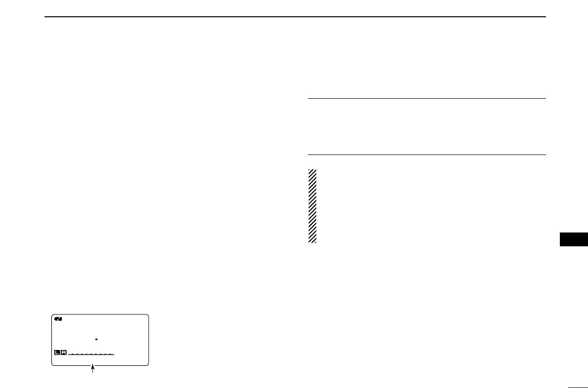
94
13
DV MODE OPERATION (Optional UT-123 is required)
1
2
3
4
5
6
7
8
9
10
13
12
13
14
15
16
17
18
19
DDMessage Transmission
Select the message transmission function ON (Ch01–05) and
OFF. When a message channel is selected, the transceiver
transmits a text message (pre-programmed). (default: OFF)
qSet the operating frequency, call signs and other settings,
such as repeater, as desired in B band.
wPerform the steps qto ein “DTX message program-
ming” as at left.
eRotate [DIAL]†to select the desired message channel.
•“Ch01” to “Ch05” available.
•See left-hand pages for message programming.
rPush [ï](5) to set the message for transmission.
tPush [PTT] to transmit the selected message.
•The message is transmitted each time [PTT] is pushed.
•The message is transmitted each 30 sec. automatically during
continuous transmission.
yRelease [PTT] to return to receive.
uWhen the reply call with a message is received, the call
sign and the message scrolls at the bottom of the function
display.
✔
For your information
The automatic received call sign and/or message indication
can be turned OFF in display set mode, if desired.
➥RX CALL SIGN (p. 100)
➥RX MESSAGE (p. 101)
NOTE: Only 1 message can be stored in the IC-
91A/91AD. The received message is cleared by turning
power OFF, or overwritten when another message is re-
ceived.
A transmitted message that includes lower case charac-
ters from the IC-91A/91AD may not be decoded and dis-
played correctly by the ID-800H, IC-V82/U82, etc.
DVDV
B
430712
50
MSG:Hello!MSG:Hello!
Scrolls the received message.

95
13 DV MODE OPERATION (Optional UT-123 is required)
DDRX message indication
The received message can also be checked in DV set mode.
qSelect “RX MESSAGE” in message/position set mode.
•The received message is displayed in RX MESSAGE screen.
wRotate [DIAL] or push [√√](8) to display the station call
sign.
ePush [ï](5) or [ΩΩ](4) to return to MESSAGE/POSITION
screen.
rPush [MENU/LOCK] to return to frequency indication.
■Automatic reply function
The automatic reply function replies to calls by a station that
specified your call sign.
Two methods of replying are available— one is making a
reply call with your own call sign, and other one is making a
reply call with reply voice audio that has been recorded in DV
voice memory.
DDAutomatic reply function setting
qEnter “AUTO REPLY” in DV set mode. (p. 92)
•AUTO REPLY screen is displayed.
wRotate [DIAL]†to select the desired reply condition.
OFF : Deactivate the automatic reply function. (default)
ON : Reply to the call with your own call sign.
VOICE : Reply to the call with the recorded voice memory.
ePush [ï](5).
•Returns to DV SET MODE screen automatically.
rPush [MENU/LOCK] to return to frequency indication.
OFF
ON
VOICEVOICE
AUTO REPLY
r
MENU screen➪DV SET MODE➪AUTO REPLY
(Push [MENU/LOCK]) (Rotate [DIAL]†, then push [ï](5)†.)
CALLER:CALLER:
BBBBBB BBBBBB
/
:MSG:MSG
:BACK:BACK
RX MESSAGERX MESSAGE
r
MESSAGE:MESSAGE:
Hello!Hello!
:CALLER:CALLER
:BACK:BACK
RX MESSAGERX MESSAGE
r
MENU screen➪MESSAGE/POSITION➪RX MESSAGE
(Push [MENU/LOCK]) (Rotate [DIAL]†, then push [ï](5)†.)

96
13
DV MODE OPERATION (Optional UT-123 is required)
1
2
3
4
5
6
7
8
9
10
13
12
13
14
15
16
17
18
19
DDVoice memory recording for automatic reply
qSelect DV mode in B band, and deactivate the priority
watch (p. 83) and weather alert function (p. 114) if activated.
wEnter “REPLY VOICE” in DV voice memo set mode.
•REPLY VOICE screen is displayed.
eWhile pushing and holding [PTT], speak into the micro-
phone.
•Up to 10 seconds of message is recordable.
•The recording stops after 10 second or when [PTT] is released.
rPush [ΩΩ](4) to return to DV VOICE MEMO screen.
tPush [MENU/LOCK] to return to frequency indication.
DDPlay-back or erase the voice memory
qPush [MENU/LOCK] to select menu mode indication.
wRotate [DIAL]†to select “DV VOICE MEMO,” then push
[ï](5)†.
eRotate [DIAL]†to select “REPLY VOICE,” then push
[ï](5)†.
•REPLY VOICE screen is displayed.
rTo play-back the recorded voice memory, push [ï](5).
•Push [ï](5) again to pause, push [≈≈](6) to cancel the play-back.
tTo erase the recorded voice memory, push and hold
[CLR](1) for 1 sec.
REPLY VREPLY V
PTT:PTT:
●
:BACK:BACK CLR:CLRCLR:CLR
REPLY VOICEREPLY VOICE
:
r
MENU screen➪DV VOICE MEMO➪REPLY VOICE
(Push [MENU/LOCK]) (Rotate [DIAL]†, then push [ï](5)†.)
IMPORTANT!
Deactivate the dualwatch function and set minimum [VOL]
level when recording the DV voice memo.
Otherwise received audio or unwanted noise from A band is
also recorded into the voice memory.
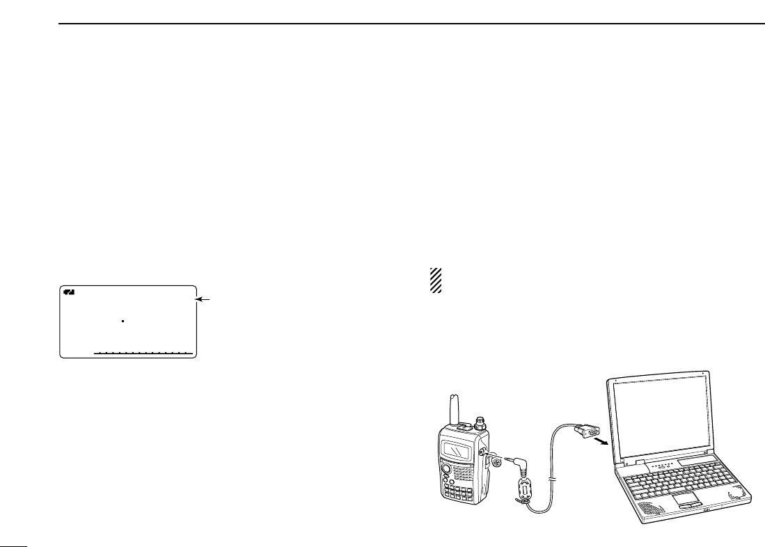
97
13 DV MODE OPERATION (Optional UT-123 is required)
■EMR communication
The EMR communication mode is available for digital mode
operation. In the EMR communication mode, no call sign set-
ting is necessary. When an EMR communication mode sig-
nal is received, the audio (voice) will be heard at the specified
level even the volume setting level is set to minimum level, or
digital call sign/digital code squelch is in use.
qSet the desired frequency in 144 or 440 MHz band then
push and hold [EMR](.) until 3 short and 1 long beeps
sound to turn the EMR setting ON.
•“EMR” appears
wOperate the transceiver normal way.
eTo cancel the EMR communication mode, push and hold
[EMR](.) for 1 sec. to turn OFF.
■
Low-speed data communication
In addition to the digital voice communication, low-speed data
communication is available.
The optional OPC-1529R
DATA COMMUNICATION CABLE
and se-
rial data communication software (purchase locally) are re-
quired in addition.
The optional RS-91
REMOTE CONTROL SOFTWARE
(OPC-1529R
supplied) also includes a low-speed data communication ca-
pability.
NOTE: Turn OFF the GPS mode (p. 58) in advance to op-
erate the low-speed data communication.
DDConnection
Connect the transceiver to your PC using with the optional
OPC-1529R as illustrated below.
OPC-1529R
(optional)
to [DATA] to
RS-232C
EMREMRDVDV
B
430712
50 Appears

98
13
DV MODE OPERATION (Optional UT-123 is required)
1
2
3
4
5
6
7
8
9
10
13
12
13
14
15
16
17
18
19
DDLow-speed data communication application
setting
Configure the low-speed data communication application as
follows.
•Port : The same COM port number as IC-
91A/91AD’s
•Baud rate : 38.4 kbps (fixed value)
•Data : 8 bit
•Parity : None
•Stop : 1 bit
•Flow control : Xon/Xoff
DDLow-speed data communication operation
NOTE: Confirm that in AUTO, the computer controls when
[PTT] is activated to send data and the user doesn’t have
to operate the radio.
qSet your own, station call signs, etc. as described in
“■Digital voice mode operation” (p. 38) and “■Digital re-
peater operation” (p. 41).
wRefer to the instructions of the low-speed data communi-
cation application.
eTo transmit data
•With your voice audio, push and hold [PTT] to transmit while
sending data from the PC. Release [PTT] to receive.
•Under computer control, see Transmission condition setting at
right.
DDTransmission condition setting
qEnter “DV DATA TX” in DV set mode. (p. 92)
wRotate [DIAL]†to select “PTT” or “AUTO.”
ePush [ï](5) (or [ΩΩ](4))to return to DV set mode, and push
[MENU/LOCK] to return to frequency indication.
MENU screen➪DV SET MODE➪DV DATA TX
(Push [MENU/LOCK]) (Rotate [DIAL]†, then push [ï](5)†.)
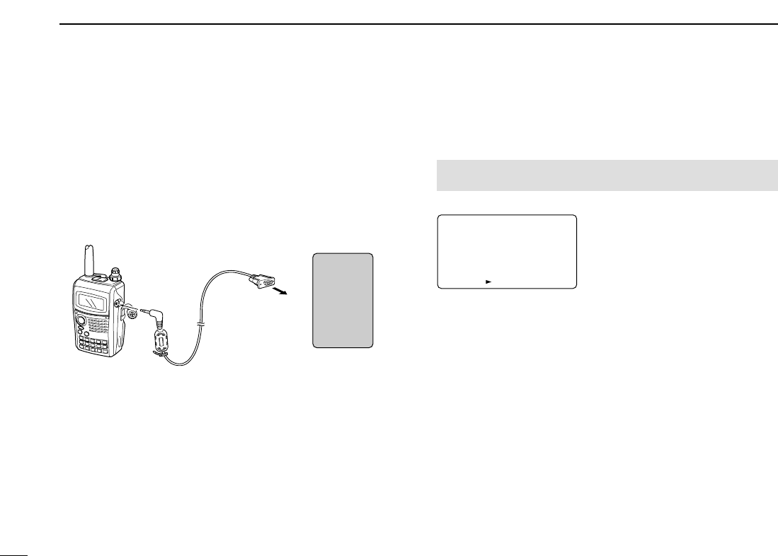
99
13 DV MODE OPERATION (Optional UT-123 is required)
■GPS operation
During GPS mode operation, a GPS receiver (RS-232C out-
put/NMEA format) can be connected to the [DATA] socket of
the IC-91A/91AD to indicate the current position (Latitude and
Longitude). The position data is transmitted with your voice sig-
nals at the same time.
In addition, the GPS message transmission is also available
for the GPS mode operation.
DDSentence formatter setting
qEnter “GPS MODE” in DV set mode. (p. 94)
•GPS MODE screen is displayed.
wRotate [DIAL]†to select “ON.”
ePush [ï](5)†to select GPS SENTENCE screen.
rRotate [DIAL]†to select the desired GPS sentence, then
push [ï](5).
•A total 5 sentences, RMC, GGA, GLL, GSA and VTG are avail-
able.
tRotate [DIAL]†to turn the sentence usage ON and OFF.
yPush [ï](5) (or [ΩΩ](4))to return to GPS SENTENCE
screen.
uRepeat the steps rto yto set another GPS sentence
usage.
•Up to 3 GPS sentences are usable at the same time.
iPush [MENU/LOCK] to return to frequency indication.
OFFOFF
ON
GPS MODEGPS MODE
:SENTENCE:SENTENCE
r
MENU screen➪DV SET MODE➪GPS MODE
(Push [MENU/LOCK]) (Rotate [DIAL]†, then push [ï](5)†.)
OPC-1529R
(optional)
to [DATA] to RS-232C port
(null modem
adapter is required)
GPS
receiver
100
13
DV MODE OPERATION (Optional UT-123 is required)
1
2
3
4
5
6
7
8
9
10
13
12
13
14
15
16
17
18
19
DDGPS message programming
qEnter “GPS” in message/position set mode.
•GPS MESSAGE screen is displayed.
wPush [≈≈](6) to select the message edit condition.
•The 1st digit of the message blinks.
eRotate [DIAL]†to select the desired character or symbol.
•Push [A/a](3) to change the character group from “AB” (alpha-
betical characters; capital letters), “ab” (alphabetical characters;
lower case letters), “12” (numbers) and “!”” (symbols) in se-
quence.
rPush [≈≈](6) to select 2nd digit, then rotate [DIAL]†to select
the desired character or code.
•Push [≈≈](6) to move the cursor right; push [ΩΩ](4) to move the
cursor left.
•2nd digit blinks (1st digit stops blinking).
tRepeat the steps rand tto enter the desired message.
•Up to 20-character messages can be set.
yPush [ï](5) to store the message.
uPush [MENU/LOCK] to return to frequency indication.
DATA: AB
Hello!Hello!
†
:SET:SET
:SEL:SEL
:CUR:CUR
CLR:CLRCLR:CLR
GPS MESSAGEGPS MESSAGE
A/a:CHARA/a:CHAR
r
DATA:DATA: AB
†
:SET:SET
:SEL:SEL
:CUR:CUR
CLR:CLRCLR:CLR
GPS MESSAGEGPS MESSAGE
A/a:CHARA/a:CHAR
r
MENU screen➪MESSAGE/POSITION➪GPS
(Push [MENU/LOCK]) (Rotate [DIAL]†, then push [ï](5)†.)
101
13 DV MODE OPERATION (Optional UT-123 is required)
DDGPS message automatic transmission
qEnter “GPS AUTO TX” in DV set mode. (p. 95)
•GPS AUTO RX screen is displayed.
wRotate [DIAL]†to select the desired position data transmit-
ting interval from 5 sec., 10 sec., 30 sec., 1 min., 3 min.,
5 min., 10 min., 30 min. and OFF.
•The position data is transmitted only when [PTT] is pushed with
OFF setting, the data is transmitted automatically once every
5 sec., 10 sec., 30 sec., 1 min., 3 min., 5 min., 10 min. and
30 min. when the appropriate setting is selected.
•The GPS message is also transmitted if programmed.
ePush [ï](5) (or [ΩΩ](4))to return to DV SET MODE screen.
rPush [MENU/LOCK] to return to frequency indication.
NOTE: Your own call sign (“MY”) should be set to activate
the GPS automatic transmission.
DDPosition indication
qEnter “POSITION” in message/position set mode.
•GPS POSITION screen is displayed.
wRotate [DIAL]†to select the received position data indica-
tion.
ePush [ï](5) (or [ΩΩ](4))to return to MESSAGE/POSITION
screen.
rPush [MENU/LOCK] to return to frequency indication.
MY POSITIONMY POSITION
GPS POSITIONGPS POSITION
r
34.56.789 N34.56.789 N
123.45.678 E123.45.678 E
:RX POS:RX POS
:BACK:BACK
MENU screen➪MESSAGE/POSITION➪POSITION
(Push [MENU/LOCK]) (Rotate [DIAL]†, then push [ï](5)†.)
OFFOFF
5SEC5SEC
10SEC10SEC
30SEC30SEC
1MIN1MIN
GPS AUTO TXGPS AUTO TX
r
MENU screen➪DV SET MODE➪GPS AUTO TX
(Push [MENU/LOCK]) (Rotate [DIAL]†, then push [ï](5)†.)

102
13
DV MODE OPERATION (Optional UT-123 is required)
1
2
3
4
5
6
7
8
9
10
13
12
13
14
15
16
17
18
19
DDReceived GPS message indication
qEnter “RX GPS” in message/position set mode.
•RX GPS MESSAGE screen is displayed.
wPush [ï](5) (or [ΩΩ](4))to return to MESSAGE/POSITION
screen.
ePush [MENU/LOCK] to return to frequency indication.
DATA:DATA:
Call from Call from
Osaka! Osaka!
:BACK:BACK
RX GPS MESSAGERX GPS MESSAGE
r
MENU screen➪MESSAGE/POSITION➪RX GPS
(Push [MENU/LOCK]) (Rotate [DIAL]†, then push [ï](5)†.)

103
13 DV MODE OPERATION (Optional UT-123 is required)
DDDV voice memory
The IC-91A/91AD has a DV voice memory that records a total
30 second (approx.) of received audio.
The DV voice memory is divided into 2 tracks, 15 seconds
each in a track, as the default setting.
◆Recording received audio
qSelect DV mode in B band, and deactivate the priority
watch (p. 83) and weather alert function (p. 114) if activated.
wWhile receiving a DV signal, push [REC].
eRotate [DIAL] to select the desired track.
•“✱” is displayed beside the track number when the selected track
has been recorded.
rPush [REC] to start recording.
•Track counter (bar meter) is displayed during record.
•The recording is paused automatically when the DV signal is in-
terrupted or when the DV audio signal cannot be received cor-
rectly. Re-starts the recording when the DV audio signal is
received correctly.
tPush [REC] again to stop recording.
•The recording stops automatically when the track becomes full.
◆Track size setting
The track size can be changed with the following instruction.
qEnter “TRACK SIZE” in DV voice memo set mode.
•TRACK SIZE screen is displayed
wRotate [DIAL]†to select the desired track size.
10S/3TRACK : Makes 3 tracks and 10 seconds audio
can be recorded in each track.
15S/2TRACK : Makes 2 tracks and 15 seconds audio
can be recorded in each track.
30S/1TRACK : Makes 1 track only and 30 seconds audio
can be recorded in a track.
ePush [ï](5) (or [ΩΩ](4))to return to DV VOICE MEMO
screen.
rPush [MENU/LOCK] to return to frequency indication.
10S/3TRACK10S/3TRACK
15S/2TRACK15S/2TRACK
30S/1TRACK30S/1TRACK
TRACK SIZETRACK SIZE
r
MENU screen➪DV VOICE MEMO➪TRACK SIZE
(Push [MENU/LOCK]) (Rotate [DIAL]†, then push [ï](5)†.)
DVDV
B
440012
50
qREC TRACK:2REC TRACK:2
■Other functions for DV mode operation

104
13
DV MODE OPERATION (Optional UT-123 is required)
1
2
3
4
5
6
7
8
9
10
13
12
13
14
15
16
17
18
19
◆Playing-back and erasing the recorded audio
qSelect DV mode in B band, and deactivate the priority
watch (p. 83) and weather alert function (p. 114) if activated.
wEnter “TRACK” in DV voice memo set mode.
•TRACK screen is displayed
eRotate [DIAL]†to select the desired audio track to be play-
back or erased.
•“✱” is displayed beside the track number when the selected track
has been recorded.
rPush [ï](5) to play-back the recorded audio.
•Push [ï](5) again to pause, push [≈≈](6) to stop play-back.
tPush and hold [CLR](1) for 1 sec. to erase the recorded
audio.
yPush [ΩΩ](4) to return to DV VOICE MEMO screen.
uPush [MENU/LOCK] to return to frequency indication.
DDDV automatic detect
The “DV” mode indicator blinks when a non-DV signal is re-
ceived during DV mode operation.
The IC-91A/91AD DV automatic detection monitors in FM
mode when other than DV mode signal is received.
qEnter “AUTO DETECT” in DV set mode. (p. 95)
wRotate [DIAL]†to turn the DV automatic detect function ON
and OFF.
OFF : “DV” mode indicator blinks, however the trans-
ceiver receives in DV mode even if non-DV mode
signals are received.
ON : “DV” mode indicator blinks and the transceiver
monitors the signal in FM mode.
ePush [ï](5) (or [ΩΩ](4))to return to DV SET MODE screen
rPush [MENU/LOCK] to return to frequency indication.
NOTE: The received FM audio may be distorted when re-
ceiving an FM signal with DV automatic detect function.
MENU screen➪DV SET MODE➪AUTO DETECT
(Push [MENU/LOCK]) (Rotate [DIAL]†, then push [ï](5)†.)
TRACK:1TRACK:1 *
::SEL:SEL
:BACK:BACK CLR:CLRCLR:CLR
TRACKTRACK
r
MENU screen➪DV VOICE MEMO➪TRACK
(Push [MENU/LOCK]) (Rotate [DIAL]†, then push [ï](5)†.)
105
OTHER FUNCTIONS
14
■General
MENU screen is used for programming infrequently changed
values or conditions of functions.
•Entering MENU screen and operation
qPush [FF•]to display the function guide.
wPush
[V/MHz•SCAN]
(Right band’s) to enter MENU screen.
eRotate the [DIAL] to select the desired menu group, then
push [MAIN•BAND].
rRotate the main band’s [DIAL] to select the desired item,
then push [MAIN•BAND].
tRotate the [DIAL] to select the desired condition or value,
then push [MAIN•BAND].
yPush [FF•]to return to frequency indication or push
[V/MHz•SCAN]
(Right band’s)
to return the back screen.
zPush [BAND] to select the main band.
xPush [
SET
B(D-OFF)] to enter set mode.
cPush [
SET
B(D-OFF)] or [
ENT
C(T-OFF)] to select
the desired item.
vPush [Y] or [Z] to select the condition or value.
bPush [
CLR
A(MW)] to exit set mode.
■Menu list
†Refer to the chapter 11 for detils.
CALL SIGN†
RX CALL SIGN†
DV MESSAGE†
DV VOICE MEMO†
SET MODE
DV SET MODE
SCAN
MENU
—
—
—
—
p. 93
p. 93
p. 93
REF.
DUP/TONE...
DISPLAY
SOUNDS
DV GPS
PACKET
GPS SET MODE
MENU
p. 94
p. 94
p. 94
p. 94
p. 94
p. 94
REF.
SET
B
106
14
OTHER FUNCTIONS
1
2
3
4
5
6
7
8
9
10
11
14
13
14
15
16
17
18
19
■Items list
DDCALL SIGN†
DDRX CALL SIGN†
DDDV MESSAGE†
DDDV VOICE MEMO†
†Refer to the chapter 11 for detils.
DDSET MODE
DDDV SET MODE
DDSCAN
SCAN TIMER
PROGRAM SKIP SCAN
ITEMS
p. 92
p. 92
REF.
BANK LINK SCAN
BANK LINK
ITEMS
p. 94
p. 94
REF.
AUTO REPLY
DIGITAL CODE
DV DATA TX
DIGITAL MONITOR
DIGITAL RPT SET
RXCALL WRITE
ITEMS
p. 92
p. 92
p. 92
p. 93
p. 93
p. 93
REF.
RXRPT WRITE
DV AUTO DETECT
EDIT RECORD
EMR
BK
ITEMS
p. 94
p. 94
p. 94
p. 94
p. 94
REF.
TIME-OUT TIMER
AUTO POWER OFF
PTT LOCK
BUSY LOCKOUT
AUTO REPEATER
FAN CONTROL
ITEMS
p. 92
p. 92
p. 92
p. 93
p. 93
p. 93
REF.
SQL DELAY
MIC SENS LEVEL
AUTO ATT
ALC
DIVERSITY
ITEMS
p. 94
p. 94
p. 94
p. 94
p. 94
REF.
TRACK
REPLY VOICE
ITEMS
—
—
REF.
TRACK SIZE
ITEMS
—
REF.
TX MESSAGE
ITEMS
—
REF.
RX MESSAGE
ITEMS
—
REF.
RX01: /
RX02: /
ITEMS
—
—
—
REF.
RX19: /
RX20: /
ITEMS
—
—
—
REF.
⋮
⋮
YOUR CALL SIGN
RPT CALL SIGN
ITEMS
—
—
REF.
MY CALL SIGN
ITEMS
—
—
REF.
107
14 OTHER FUNCTIONS
DDDUP/TONE
DDDISPLAY
DDSOUNDS
DDDV GPS
DDPACKET
DDGPS SET MODE
GPS SPEED
LINEAR MEASURE
UTC OFFSET
ITEMS
p. 92
p. 92
p. 92
REF.
GPS DATUM
POS AREA1
POS AREA2
ITEMS
p. 94
p. 94
p. 94
REF.
PACKET BPS
ITEMS
p. 92
REF.
PACKET BAND
ITEMS
p. 94
REF.
GPS SENTENCE
GPS MESSAGE
RX GPS MESSAGE
ITEMS
p. 92
p. 92
p. 92
REF.
GPS TX
GPS AUTO TX
ITEMS
p. 94
p. 94
REF.
KEY-TOUCH BEEP
BEEP LEVEL
SCOPE AF OUTPUT
ITEMS
p. 92
p. 92
p. 92
REF.
SUB BAND MUTE
SUB BAND BEEP
STANDBY BEEP
ITEMS
p. 94
p. 94
p. 94
REF.
BACKLIGHT
DIMMER
AUTO DIMMER
LCD CONTRAST
OPENING LOGO
ITEMS
p. 92
p. 92
p. 92
p. 93
p. 93
REF.
OPENING CALL S
SCAN NAME
RX CALL SIGN
TX CALL SIGN
RX MESSAGE
ITEMS
p. 94
p. 94
p. 94
p. 94
p. 94
REF.
OFFSET FREQ
REPEATER TONE
CTCSS TONE
DTCS CODE
DTCS POLARITY
ITEMS
p. 92
p. 92
p. 92
p. 93
p. 93
REF.
WX ALERT
PGR/CSQL
PGR/ CODE
DTMF SPEED
ITEMS
p. 94
p. 94
p. 94
p. 94
REF.

108
14
OTHER FUNCTIONS
1
2
3
4
5
6
7
8
9
10
11
14
13
14
15
16
17
18
19

109
14 OTHER FUNCTIONS
■SET MODE items
DDTime-out timer
To prevent accidental prolonged transmission, etc., the trans-
ceiver has a time-out timer. This function cuts a transmission
OFF after 1, 3 or 5 min. of continuous transmission. This timer
can be cancelled.
•OFF : The time-out timer is turned OFF. (default)
•1, 3, 5 MIN : The transmission is cut OFF after the set
period elapses.
DDAuto power OFF
The transceiver can be set to automatically turn OFF after a
specified period with a beep when no key operations are per-
formed.
30 min, 60 min, 120 min and OFF (default) can be specified.
The specified period is retained even when the transceiver is
turned OFF by the auto power OFF function. To cancel the
function, select “OFF” in this set mode.
DDPTT lock
Turns the PTT lock function ON and OFF(default.)
Transmission with [PTT] is inhibited when ON is selected to
prevent accidental transmission, etc.
DDBusy lockout
Turns the busy lockout function ON and OFF(default.)
This function inhibits transmission while receiving a signal or
when the squelch is open
DDAuto repeater
The auto repeater function automatically turns ON or OFF the
duplex operation and tone encoder. The offset and repeater
tone is not changed by the auto repeater function. Reset
these frequencies, if necessary.
U.S.A. version:
•OFF : The auto repeater function is turned OFF.
•RPT1 : Activates for duplex only. (default)
•RPT2 : Activates for duplex and tone.
Korean version:
•OFF : Deactivates the function.
•ON : Activates duplex and tone. (default)
DDFan control
Selects the cooling fan control condition from AUTO, HI, MID
and LOW.
•AUTO: The fan rotates during transmit and for 2 min.
after transmission.(default)
•HI : The high power fan continuously rotates.
•MID : The middle power fan continuously rotates.
•LOW : The low power.fan continuously rotates.
U.S.A./KOREAN versions only

110
14
OTHER FUNCTIONS
1
2
3
4
5
6
7
8
9
10
11
14
13
14
15
16
17
18
19
DDSquelch delay
Selects squelch delay from short and long to prevent re-
peated opening and closing of the squelch during reception
of the same signal.
•Short : Short squelch delay. (default)
•Long : Long squelch delay
DDMic sens level
Selects the microphone sensitivity from HIGH (default) and
LOW to suit your preference.
DDAuto ATT
The attenuator prevents distortion of a desired signal by very
strong RF signals near the desired frequency or when very
strong electric fields, such as from a broadcasting station, are
present at your location.
Select the attenuator function ON (default) and OFF.
DDALC
Sets the ALC (automatic Level Control) function ON and OFF
(default)
The ALC function reduces the microphone again automati-
cally when the transmission audio is distored.
DDDiversity
Turns the diversity function ON and OFF(default.)
.
■DV SET MODE items
The following items are selectable by optional UT-123 is in-
stalled into the IC-2820H.
DDAuto reply
This function replies to an individual station call even you are
away from the transceiver.
After a manual transmission (pushing [PTT]), the Auto Reply
setting returns to OFF automatically.
• OFF : No reply is performed even a call is received.
(default)
• ON : Sets caller’s call sign and reply to the call with
the set own call sign automatically.
DDDigital code
Sets the desired digital code for digital code squelch opera-
tion. Total of 100 codes (0–99) are available. (default: 0)
DDDV data TX
During low-speed data operation, auto data transmission
function is available. This function transmits when data has
been input from PC via the [DATA] jack. (default: PTT)

111
14 OTHER FUNCTIONS
DDDigital monitor
Sets the desired monitoring mode during DV MODE OPERA-
TION (Optional UT-123 is required) from “Auto,” “Digital” and
“Analog.”
• AUTO : The transceiver sets monitoring mode to FM
and DV according to the received signal. (de-
fault)
• DIGITAL : Monitors in DV mode.
• ANALOG : Monitors in FM mode.
DDDigital repeater setting
When accessing a digital repeater with a call sign different
than is programmed, the repeater call sign can be stored into
“RPT1” and/or “RPT2” automatically by reading the repeater’s
transmission. The stored repeater’s call sign can be re-called
when selecting the repeater call sign. (default: ON)
DDRX call sign auto write
When an individual station call is received, the calling station
call sign can be automatically set in “UR.” (default: OFF)
DDRepeater call sign auto write
When accessing a repeater with a call sign different than is
programmed, the repeater call sign can be set into “RPT1”
and or “RPT2” automatically by reading the repeater’s trans-
mission. (default: OFF)
The transceiver sets the received repeater call sign for op-
eration. Therefore, when a different call sign is set for op-
eration, the previously set repeater call sign will be lost.
DDDV auto detect
When a signal other than DV mode is received during DV
mode operation, the transceiver has capability of automatic
FM mode selection.
• OFF : Operating mode is fixed in DV. (default)
• ON : The transceiver automatically selects FM
mode for temporary operation.
DDCall sign edit record
Selects the call sign programming when the call sign is edited
or corrected with the pre-programmed call sign.
• OFF : The edited or corrected call sign is over writ-
ten.
• SELECT : The edited or corrected call sign is pro-
grammed into the selected call sign memory.
• AUTO : The edited or corrected call sign is pro-
grammed into a blank channel automatically.
(default)

112
14
OTHER FUNCTIONS
1
2
3
4
5
6
7
8
9
10
11
14
13
14
15
16
17
18
19
DDEMR comunication
Turns the EMR comunication mode ON and OFF. (default)
DDBreak-in comunication
Turns the break-in comunication mode ON and OFF. (default)
■SCAN items
DDScan timer
Selects scan resume timer from T-15, T-10 (default), T-5 and
P-2.
•T-15/10/5 : Scan pauses for 15/10/5 sec., then resumes.
•P-2 : Pause on a signal until signal disappears,
then resumes 2 sec. after the signal disap-
pears.
DDProgram skip scan
Sets channel skip setting from ON (default) and OFF for
memory skip scan operation.
This item appears when set mode is accessed from memory
mode only.
DDBank link scan
Sets the memory bank link function ON (default) and OFF. The
link function provides continuous bank scan, scanning all con-
tents in the selected banks during bank scan.
•Bank link setting
q
Enter MENU screen in function guide.
wRotate the main band’s [DIAL] to select “SCAN” set mode,
then push [MAIN•BAND].
eRotate the [DIAL] to select “BANK LINK”, then push
[MAIN•BAND] to enter bank setting.
rRotate the [DIAL] to select the desired bank initial, then
push [MAIN•BAND].
tRotate [DIAL] to turn ON (default) and OFF, then push
[MAIN•BAND].
yRotate [DIAL] to select next bank and repeat steps rto
t, or push [FF•] to exit scan set mode.
113
14 OTHER FUNCTIONS
■DUP/ TONE items
DDOffset frequency
Sets the duplex offset frequency within 0 to 159.995 MHz
range. During duplex (repeater) operation, transmit frequency
shifts the set frequency. (default value may differ depending on
operating frequency band and versions)
DDRepeater tone
Sets subaudible tone frequency (encoder only) for repeater
operation. Total of 50 tone frequencies (67.0–254.1 Hz) are
available. (default: 88.5 Hz)
DDCTCSS tone
Sets subaudible tone frequency (both encoder and decoder)
for tone squelch operation. Total of 50 tone frequencies
(67.0–254.1 Hz) are available. (default: 88.5 Hz)
•Available subaudible tone frequencies
DDDTCS code
Sets DTCS code (both encoder and decoder) for DTCS
squelch operation. Total of 104 codes are available.
(default: 023)
•Available DTCS codes
DDDTCS polarity
Sets DTCS polarities for transmission and reception from
“BOTH N,” “TN-RR,” “TR-RN” and “BOTH R”
(default: BOTH N)
DDWeather alert function
Turns weather alert function ON and OFF.
See.P?? detale.
DDPGR/C-SQL
Sets DTCS polarities for transmission and reception from
“BOTH N,” “TN-RR,” “TR-RN” and “BOTH R”
(default: BOTH N)
U.S.A. version only
023
025
026
031
032
036
043
047
051
053
125
131
132
134
143
145
152
155
156
162
245
246
251
252
255
261
263
265
266
271
356
364
365
371
411
412
413
423
431
432
506
516
523
526
532
546
565
606
612
624
054
065
071
072
073
074
114
115
116
122
165
172
174
205
212
223
225
226
243
244
274
306
311
315
325
331
332
343
346
351
445
446
452
454
455
462
464
465
466
503
627
631
632
654
662
664
703
712
723
731
732
734
743
754
67.0
69.3
71.9
74.4
77.0
79.7
82.5
85.4
88.5
91.5
94.8
97.4
100.0
103.5
107.2
110.9
114.8
118.8
123.0
127.3
131.8
136.5
141.3
146.2
151.4
156.7
159.8
162.2
165.5
167.9
171.3
173.8
177.3
179.9
183.5
186.2
189.9
192.8
196.6
199.5
203.5
206.5
210.7
218.1
225.7
229.1
233.6
241.8
250.3
254.1

114
14
OTHER FUNCTIONS
1
2
3
4
5
6
7
8
9
10
11
14
13
14
15
16
17
18
19
DDPGR/CODE
Sets DTCS polarities for transmission and reception from
“BOTH N,” “TN-RR,” “TR-RN” and “BOTH R”
(default: BOTH N)
DDDTMF speed
The rate at which DTMF memories send individual DTMF
characters can be set to accommodate operating needs.
•100 : 100 msec. interval; 5.0 cps speed (default)
•200 : 200 msec. interval; 2.5 cps speed
•300 : 300 msec. interval; 1.6 cps speed
•500 : 500 msec. interval; 1.0 cps speed
■DISPLAY items
DDBack light
Adjust to suit back color conditions.The levels change led to
green. led (Left)➔ yellow green ➔ green (Right)
(default: yellow green)
DDDisplay dimmer
Adjust to suit back lighting conditions.
The levels 1 (dark) to 8 (bright: default) are available.
DDAuto dimmer
Turns the auto dimmer function OFF, AUTO–OFF, AUTO–D1
to AUTO–D7.
• OFF : Opening logo is displayed at power
ON. (default)
• AUTO–OFF : Opening logo indication is skipped.
• AUTO–D1 to D7 : Opening logo indication is skipped.
DDLCD contrast
The contrast of the LCD can be selected from 16 levels.
•1 (Low contrast) to 16 (High contrast) (default: 8)
DDOpening logo
The opening logo indication (Icom logo and transceiver name)
that is displayed at power ON can be skipped, if desired.
• ON : Opening logo is displayed at power ON. (default)
• OFF : Opening logo indication is skipped.

115
14 OTHER FUNCTIONS
DDOpening call sign
☞Available only when the
UT-123 is installed.
The set your own call sign, programmed in my call sign, can
be displayed at power ON. (default: OFF)
DDScan name
The programmed scan or bank name is displayed during the
scan type selection.
•ON : The programmed scan or bank name is dis-
played. (default)
•OFF : The programmed scan or bank name is not dis-
played.
DDRX Call Sign Display
☞Available only when the
UT-123 is installed.
When a call is received, the calling station call sign can be in-
dicated automatically. (default: OFF)
DDTX Call Sign Display
☞Available only when the
UT-123 is installed.
Selects call sign display function from YOUR, MY and OFF.
When this setting is set to YOUR or MY, the transceiver auto-
matically indicates the set station or your own call sign at dig-
ital mode transmission. (default: YOUR)
DDRX message Display
☞Available only when the
UT-123 is installed.
Sets auto received message display function AUTO and OFF.
When this setting is set to AUTO, the transceiver automati-
cally indicates and scrolls the received message.
(default: AUTO)

116
14
OTHER FUNCTIONS
1
2
3
4
5
6
7
8
9
10
11
14
13
14
15
16
17
18
19
■SOUND items
DDKey-touch beep
The key-touch beep can be turned OFF for silent operation.
(default: ON)
DDBeep level
Adjusts the key-touch beep tone level to the desired level
from 9 levels.
•1 (Minimum level) to 9 (Maximum level) (default: 5)
The key-touch beep function must be set to ON to have a
beep tone.
DDScope AF output
Select the audio output function capability during sweep with
band scope function.
•ON : The received audio sounds during sweep. (default)
•OFF : No audio sounds during sweep.
DDSub band mute
Turns the sub band mute function capability ON and OFF (de-
fault).
DDSub band beep
Turns the sub band busy beep function capability ON and
OFF. (default)
DDStandby Beep
☞Available only when the
UT-123 is installed.
Turns the beep emission capability ON and OFF when the com-
municating station finishes transmitting or the receive signal dis-
appears while in the DV MODE OPERATION (Optional UT-123
is required).
(default: ON)

117
14 OTHER FUNCTIONS
■DV GPS items
DDGPS sentence
qEnter the MENU screen in the function guide.
wRotate the main band’s [DIAL] to select “DV GPS,” then
push the main band’s [MAIN•BAND] to enter the sentence
formatter selection.
eRotate [DIAL] to select the desired sentence formatter.
•RMC, GGA, GLL, GSA and VTG are selectable.
rPush [MAIN•BAND] to enter the desired sentence format-
ter selection.
tRotate [DIAL] to select the setting, then push
[MAIN•BAND].
yRotate [DIAL] to select next sentence and repeat steps e
to t, or push [FF•] to return to frequency indication.
•Only three sentence formatters can be activated at same time.
DDGPS message
See P?? to the chapter 13 for detils.
DDRX GPS message
Selects the data transmission speed for packet operation
from 1200 bps (default) and 9600 bps.
DDGPS TX
GPS transmission function select “ENABLE” or “DISABLE.”
(default: ENABLE)
DDGPS auto TX
Selects the desired interval for automatic position transmis-
sion function from 5, 10, 30 second, 1, 3, 5, 10 and 30 min-
utes. (default: OFF)

118
14
OTHER FUNCTIONS
1
2
3
4
5
6
7
8
9
10
11
14
13
14
15
16
17
18
19
■PACKET items
DDPacket BPS
Selects the data transmission speed for packet operation
from 1200 bps (default) and 9600 bps.
DDPacket operation band
Selects the packet operation band from main, right and left.
•MAIN : The main band is used for packet op-
eration.
•L(Left)/R(Right) : The selected left or right band can
only be operated for packet.
■GPS SET MODE items
DDGPS SPEED
Selects the data transmission speed for packet operation
from 4800 bps (default) and 9600 bps.
DDLINEAR MEASURE
Linear measure function select “m” (default) or “ft/ml.”
DDCOMPASS
Compass function select “ARROWHEAD” (default), “NORTH
REF”, “SOUTH REF.”
DDUTC OFFSET
Selects the UTC offset -12:00 to +12:00. Turn every 5 min-
utes. (default: 0:00)
DDGPS DATUM
Selects the GPS datum 0 (default) to 224.
DDPOS AREA1
Selects the data transmission speed for packet operation
from 1200 bps (default) and 9600 bps.
DDPOS AREA2
Position area2 select “AUTO” (default), “FAR”, “NEAR.”
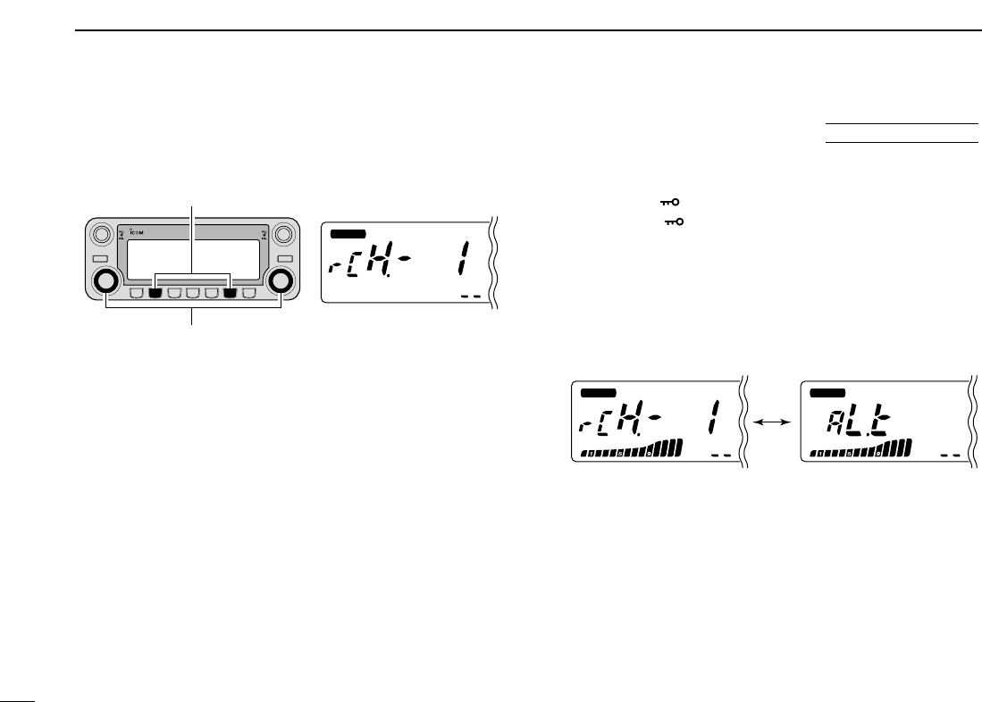
119
14 OTHER FUNCTIONS
DDWeather channel selection
qPush the desired band’s [M/CALL•MW] several times to
select weather channel group.
wRotate the same band’s [DIAL] to select the desired
weather channel.
ePush the [M/CALL•MW] to select memory mode, or push
the main band’s [V/MHz•SCAN] to select VFO mode.
DDWeather alert function
NOAA broadcast stations transmit weather alert tones before
important weather announcements. When the weather alert
function is turned ON, the selected weather channel is moni-
tored each 5 sec. for the announcement. When the alert sig-
nal is detected, the “AL.t” and the WX channel are displayed
alternately and sounds a beep tone until the transceiver is op-
erated. The previously selected (used) weather channel is
checked periodically during standby or while scanning.
qSelect the desired weather channel.
wTurn the weather alert function ON in set mode.
➥Push [FF•]to enter set mode.
➥Push [FF•]or [LOW•PRIO] to select the weather
alert item, then rotate the [DIAL] to set ON.
➥Push [TONE•DTMF] to exit set mode.
eSets the desired stand-by condition.
•Selects VFO, memory or call channel.
•Scan or priority watch operation can also be selected.
rWhen the alert is detected, a beep sounds and the follow-
ing indication will be displayed.
tTurn the weather alert function OFF in “DUP/TONE” set
mode.
☞NOTE: While receiving a signal (on a frequency other than
the weather alert ON frequency), the receiving signal or
audio will be interrupted momentarily every 5 sec. (approx.)
in case the alert function is turned ON. This symptom is
caused by the WX alert function. To cancel these symp-
toms, set the weather alert item OFF in “DUP/TONE” set
mode.
BUSY
MAIN
T X
M
BUSY
MAIN
T X
M
Shows above indications alternately.
MAIN
T X
M
DUO BAND TRANSCEIVER i2820
Weather channel group
indicaiton
[M/CALL•MW]
[DIAL]
■Weather channel operation U.S.A. version only

120
14
OTHER FUNCTIONS
1
2
3
4
5
6
7
8
9
10
11
14
13
14
15
16
17
18
19
■Microphone keys
The supplied HM-133’s (optional for some versions) [F-1] and
[F-2] keys memorize the transceiver conditions.
The [UP]/[DN] keys of the standard or an optional microphone
(other than the HM-133) can be assigned functions like the
function keys on the transceiver’s front panel.
DD[UP]/[DN] keys on a microphones
(other than HM-133)
The following functions are assigned to the [UP]/[DN] keys on
the other microphones (HM-118N/TAN, etc.) when first apply-
ing power.
•Default setting
[UP] : channel up; push and hold to start scan, push again
to stop scan.
[DN] : channel down; push and hold to start scan, push
again to stop scan.
➥Assigning a function
qTurn the power OFF.
wWhile pushing the desired key on the transceiver and one
of either [UP]/[DN] keys on the microphone, turn the power
ON.
•The function is programmed into the key.
➥Clearing an assignment
qTurn the power OFF.
wWhile pushing the desired [UP] or [DN] key on the micro-
phone, turn the power ON.
DD[F-1]/[F-2] keys on HM-133
The following conditions in the main band or both left and
right bands can be memorized into [F-1] and [F-2] keys, in-
dependently.
•Operating frequency
•Repeater setting (offset direction and frequency, tone ON/OFF
and frequency)
•Tone/DTCS squelch (ON/OFF, frequency/code and polarity)
•Transmit output power selection
•Tuning step
•Operating mode selection (FM/AM)
•Set mode settings*
•Initial set mode settings*
*Only when storing both bands conditions
➥Programming the both bands condition
After setting the desired contents of each
condition in the both bands, push [FUNC]
then push [F-1]/[F-2] for 1 sec.
•3 beeps sound.
➥Recalling the both bands condition
Push [FUNC] then [F-1]/[F-2] momentarily.
➥Programming the main band condition
Set the desired contents of each condition in
the main band, then push [F-1]/[F-2] for 1 sec.
•3 beeps sound.
➥Recalling the main band condition
Push [F-1]/[F-2] momentarily.
[F-1]/[F-2]
AT
POWER ON
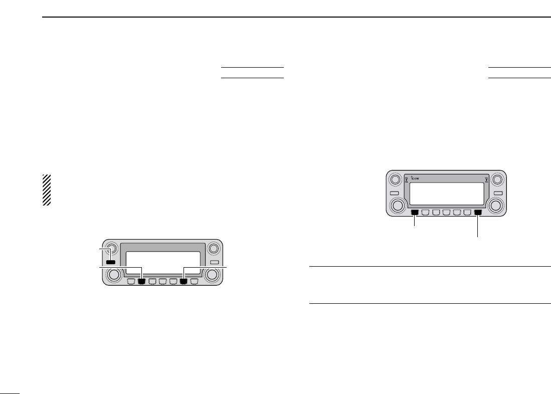
121
14 OTHER FUNCTIONS
■ALL reset
The function display may occasionally display erroneous in-
formation (e.g. when first applying power). This may be
caused externally by static electricity or by other factors.
If this problem occurs, turn power OFF. After waiting a few
seconds, turn power ON again. If the problem persists, per-
form the following procedure.
•Partial resetting is also available. See left for details.
IMPORTANT!:
Resetting the transceiver CLEARS all memory information
and initializes all values in the transceiver.
➥While pushing both band’s [M/CALL•MW], turn the power
ON to reset the CPU.
■Partial reset
If you want to initialize the operating conditions (VFO fre-
quency, VFO settings, menu group’s contents) without clear-
ing the memory contents, a partial resetting function is
available for the transceiver left and right bands indepen-
dently.
➥While pushing desired band’s [V/MHz•SCAN], turn the
power ON to partially reset the desired band (left or right).
✔
Hint!
When pushing both [V/MHz•SCAN] and turning the power
ON, partially reset both bands at the same time.
DUO BAND TRANSCEIVER i2820
Left band partial reset.
Right band partial reset.
AT
POWER ON
[M/CALL•MW]
While pushing both [M/CALL•MW], turn power ON.
[M/CALL•MW]
[PWR]
AT
POWER ON
122
14
OTHER FUNCTIONS
1
2
3
4
5
6
7
8
9
10
11
14
13
14
15
16
17
18
19
■Data cloning
Cloning allows you to quickly and easily transfer the pro-
grammed contents from one transceiver to another; or , data
from a personal computer to a transceiver using the optional
CS-2820
CLONING SOFTWARE
.
DCloning between transceivers
qConnect the OPC-474 cloning cable to the [SP-2] jack of
the master and sub-transceivers.
•The master transceiver is used to send data to the sub-trans-
ceiver.
wWhile pushing left band’s [M/CALL•MW], turn power ON
to enter cloning mode (master transceiver only— power on
only for sub-transceiver).
•“CLOnE” appears and the transceivers enter the clone standby
condition.
ePush the same [M/CALL•MW] on the master transceiver.
•“CLOnE OUt” appears in the master transceiver’s display and
the S/RF indicators show that data is being transferred to the
sub-transceiver.
•“CLOnE In” appears automatically in the sub-transceiver’s dis-
play and the S/RF indicators show that data is being received
from the master transceiver.
rWhen cloning is finished, turn power OFF, then ON to exit
cloning mode.
MAIN
T X
MAIN
T X
MM
DUO BAND TRANSCEIVER i2820
Pushing left band’s [M/CALL•MW] start cloning.
MAIN
T X
MAIN
T X
MM
DUO BAND TRANSCEIVER i2820
While pushing left band’s [M/CALL•MW], turn power ON.
To [SP-2] To [SP-2]
AT
POWER ON
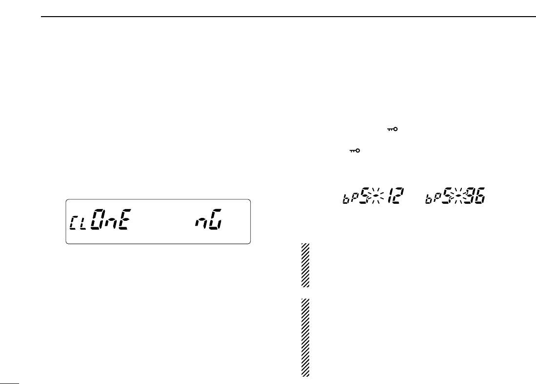
123
14 OTHER FUNCTIONS
DCloning using a personal computer
Data can be cloned to and from a personal computer (Mi-
crosoft®Windows®98/2000/Me/XP) using the optional CS-
2820
CLONING SOFTWARE
and the optional cloning cable
OPC-478U (USB type) or OPC-478 (RS-232C type). Consult
the CS-2820
CLONING SOFTWARE
HELP file for details.
DCloning error
☞NOTE: DO NOT push any key on the sub-transceiver dur-
ing cloning. This will cause a cloning error.
When the display as below appears, a cloning error has oc-
curred.
In such a case, both transceivers automatically return to the
clone standby condition and cloning must be repeated.
■Packet operation
DData speed
For packet operation, the transceiver can be set to one of two
data speeds: 1200 bps (default) or 9600 bps.
qWhile pushing [FF•]turn power ON to enter initial set
mode.
wPush
[FF•]
or [LOW•PRIO] to select the ‘bPS’item.
eRotate the left band [DIAL] to select the desired data
speed.
rPush [PWR] to exit initial set mode.
For 1200 bps operation—
•Disconnect the microphone plug from the microphone
connector during data transmission, otherwise the data
signal and voice signal are simultaneously transmitted.
For 9600 bps operation—
•When the transceiver is set for 9600 bps data transmis-
sion in set mode, the microphone signal is automatically
cut. Therefore, it is not necessary to disconnect the mi-
crophone plug from the connector in this case.
•
When pushing [PTT] during data transmission, data trans-
mission is interrupted and voice signals have priority.
MAIN
T X
M
MAIN
T X
M
MAIN
T X
MAIN
T X
MM
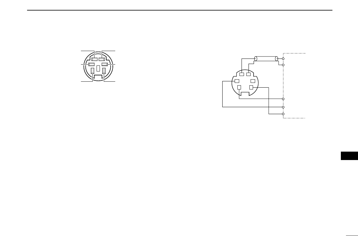
124
14
OTHER FUNCTIONS
1
2
3
4
5
6
7
8
9
10
11
14
13
14
15
16
17
18
19
DDATA JACK PIN ASSIGNMENT
qDATA IN
Input terminal for data transmit. See p. ?? for details on
how to toggle data speed between 1200 (AFSK) and
9600 bps (G3RUH, GMSK).
wGND
Common ground for DATA IN, DATA OUT and AF OUT.
ePTT P
PTT terminal for packet operation only. Connect ground to
transmit data.
rDATA OUT
Data out terminal for 9600 bps operation only.
tAF OUT
Data out terminal for 1200 bps operation only.
yP SQL
Becomes high (+5 V) when the transceiver receives a sig-
nal which opens the squelch.
•To avoid unnecessary TNC transmission, connect squelch to the
TNC to inhibit transmission when receiving signals.
•Keep audio output at a normal level, otherwise a “P SQL” signal
will not be output.
D1200 bps packet operation
qConnect the transceiver and a TNC as illustrated below.
wSet the TNC for transmit.
eSet transmit delay on the TNC to 30–50.
rAdjust the TNC frequency deviation if necessary.
•When using a deviation meter:
Adjust the output of the TNC so that frequency deviation
is in the range ± 3 to ±4 kHz.
•When NOT using a deviation meter:
A receiver or transceiver is needed to monitor the trans-
mission—compare the received audio output level when
receiving a TNC modulated signal with high level voice
signals using the microphone. Then adjust the TNC mod-
ulated signal to a lower level than the voice modulated
signal.
SQL
PTT
RX AUDIO
GND
TX AUDIO
TNC side
q DATA IN
w GND
e PTT P
t AF OUT
y P SQL
Front panel view
w
y
r
q
e
t
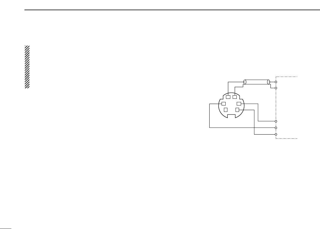
125
14 OTHER FUNCTIONS
•Read the instructions supplied with your TNC carefully
before attempting packet operation with the transceiver.
•Pin tAF OUT is for 1200 bps operation only. This pin
cannot be used for 9600 bps operation.
•Over modulation may degrade signal quality. If you find
that many transmissions are failing, re-adjust the modu-
lation level.
D9600 bps high speed packet operation
The transceiver supports 2 modes of 9600 bps packet opera-
tion: G3RUH and GMSK.
qConnect the transceiver and a TNC as illustrated below.
wG3RUH mode can handle 16 kinds of modulated wave
forms in order to maintain a communication link.
eSet transmit delay on the TNC to 30–50.
rAdjust the TNC frequency deviation if necessary (see page
at right).
TNC side
SQL
PTT
RX AUDIO
GND
TX AUDIO
q DATA IN
w GND
e PTT P r DATA OUT
y P SQL

126
14
OTHER FUNCTIONS
1
2
3
4
5
6
7
8
9
10
11
14
13
14
15
16
17
18
19
•When using the PTT P terminal for packet operation, no
voice signals are transmitted from the microphone.
•When pushing [PTT] during data transmission, data
transmission is interrupted and the voice signal takes pri-
ority.
•Read the instructions supplied with your TNC carefully
before attempting packet operation with the transceiver.
•Pin rDATA OUT is for 9600 bps operation only. This pin
cannot be used for 1200 bps operation.
DAdjusting the transmit signal output from
the TNC
When setting data transmission speed to 9600 bps, the data
signal coming from the TNC is applied exclusively to the in-
ternal limiter circuitry to automatically maintain band width.
NEVER apply data levels from the TNC of over 0.6 V p-p, oth-
erwise the transceiver will not be able to maintain the band
width and may possibly interfere with other stations.
1. When using a level meter or synchroscope, adjust the
TX audio output level (DATA IN level) from the TNC as
follows.
0.4 V p-p (0.2 V rms) : recommended level
0.2 V p-p–0.5 V p-p (0.1–0.25 V rms) : acceptable level
2. When NOT using a measuring device.
qConnect the transceiver to a TNC.
wEnter a test mode (“CAL”, etc.) on the TNC, then trans-
mit some test data.
eWhen the transceiver fails to transmit the test data or
transmits sporadically (TX indicator doesn’t appear or
flashes):
- Decrease the TNC output level until the transmit indi-
cator lights continuously.
When transmission is not successful even though the
TX indicator lights continuously:
- Increase the TNC output level.

127
MAINTENANCE
13
PROBLEM POSSIBLE CAUSE SOLUTION REF.
■Troubleshooting If your transceiver seems to be malfunctioning, please check
the following points before sending it to a service center.
Does not turn on.
No sound comes from the
speaker.
Sensitivity is low and only
strong signals are audible.
No contact possible with
another station.
Repeater cannot be ac-
cessed.
Frequency cannot be set.
Frequency cannot be set
via the microphone.
•Power connector has a poor contact.
•Polarity of the power connection is reversed.
•Blown fuse.
•Volume is too low.
•The audio mute function is activated.
•Squelch is set too high.
•A selective call or squelch function is activated
such as pocket beep or tone squelch.
•Antenna feedline or the antenna connector has a
poor contact or is short circuited.
•Squelch attenuator function is activated.
•The other station is using tone squelch.
•The transceiver is set to duplex.
•Wrong offset frequency is programmed.
•Wrong subaudible tone frequency is programmed.
•The frequency lock function is activated.
•Priority watch is paused on the watching frequency.
•The frequency lock function is activated.
•The microphone keypad lock function is activated.
•Priority watch is paused on the watching fre-
quency.
•Check the connector pins.
•Re-connect the power cable observing the proper
polarity. Replace the fuse if damaged.
•Check the cause, then replace the fuse.
•Rotate [VOL] clockwise.
•Push any key to deactivate it.
•Set the squelch level to the threshold.
•Turn the appropriate function OFF.
•Check, and if necessary, replace the feedline or sol-
der the antenna connector again.
•Set [SQL] between 10–12 o’clock position.
•Turn the tone squelch function ON.
•Set to simplex.
•Correct the offset frequency.
•Correct the subaudible tone frequency.
•Turn the function OFF.
•Push [LOW•PRIO] for 1 sec. to cancel the watch.
•Turn the function OFF
•Push [FUNC] then [sqlZ#(16KEY-L)] to deactivate
the microphone keypad lock function.
•Push [LOW•PRIO] for 1 sec. to cancel the watch.
—
pgs. VI,
74
p. 74
p. 16
p. 21
p. 16
pgs. 52,
53, 54
p. VII
p. 17
p. 54
p. 23
p. 27
p. 25
p. 15
p. 47
p. 15
p. 15
p. 47
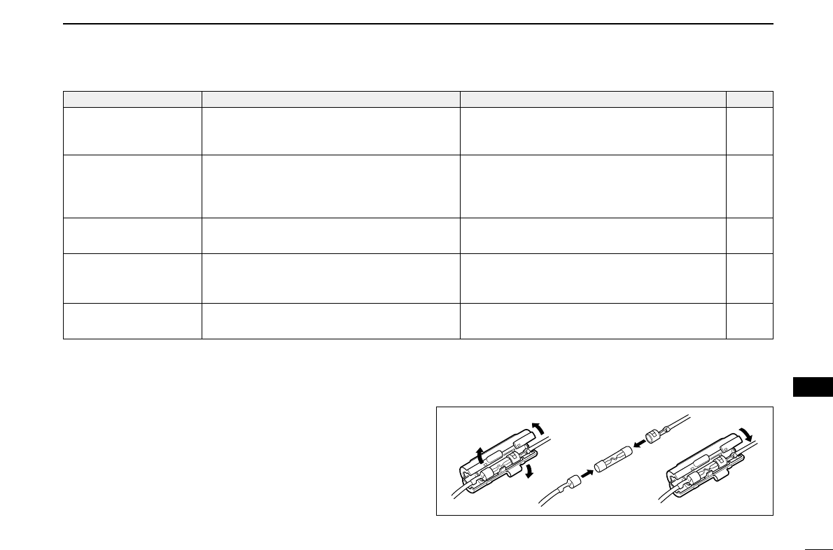
128
13
MAINTENANCE
1
2
3
4
5
6
7
8
9
10
11
12
13
14
15
16
17
18
19
PROBLEM POSSIBLE CAUSE SOLUTION REF.
Some memory channels
cannot be selected via the
tuning dial.
Scan does not operate.
Transmission is automati-
cally cut off.
Transmission continues
even when the PTT is re-
leased.
The function display shows
erroneous information.
•The memory channel number has not yet been
programmed.
•The squelch is open.
•Only 1 memory channel is programmed or other
channels are set as skip channels.
•Priority watch is activated.
•Time-out timer is activated.
•One-touch PTT function is activated.
•The CPU is malfunctioning.
•Select the channel via the microphone keypad to
check whether the channel has been programmed
or not.
•Set the squelch to the threshold point.
•Program other memory channels or cancel the
memory skip function in the desired channels.
•Cancel the watch.
•Set the timer to OFF.
•Turn the function OFF.
•Reset the CPU.
—
p. 16
pgs. 30,
31, 44
p. 47
p. 61
p. 21
p. 67
■Fuse replacement
If the fuse blows or the transceiver stops functioning, find the
source of the problem if possible, and replace the damaged
fuse with a new, rated one (FGB 20 A) as shown at right.
20 A
fuse
129
SPECIFICATIONS AND OPTIONS
14
■Specifications
DDGENERAL
•Frequency coverage : (unit: MHz)
*1Guaranteed: 144–148 MHz range only.; *2Guaranteed: 440–450 MHz range for the USA,
430–440 MHz for the General version; *3Not guaranteed; *4824.010 to 848.990 and
869.010 to 893.990 MHz ranges are inhibited for USA version and not guaranteed.
•Type of emission : FM, AM (Receive only),
DV (optional UT-123 is required)
•Number of memory channels : 522 (incl. 20 scan edges and 2 calls)
•Frequency resolution : 5, 6.25, 10, 12.5, 15, 20, 25, 30, 50 kHz
•Operating temperature range : –10°C to +60°C; +14˚F to +140˚F
•Frequency stability : ±2.5 ppm (–10°C to +60°C)
•Power supply requirement : 13.8 V DC ±15%
•Current drain (at 13.8 V DC: approx.):
Transmit at 50 W 13 A
Receive standby 1.2 A
(simultaneous receive) max. audio 1.8 A
•Antenna connector : SO-239 (50 Ω)×2 (Tx/Rx and Diversity)
•Dimensions (proj. not included) :
Main Unit 150(W) ×40(H) ×187.7(D) mm
529⁄32(W)×19⁄16(H)×713⁄32(D) in
Remote controller 150(W) ×58(H) ×31.5(D) mm
529⁄32(W)×29⁄32(H)×11⁄4(D) in
•Weight (approx.) :
Main unit (incl. separation cable) 1.5 kg; 3 lb 5 oz
Remote controller 210 g; 7.4 oz
DDTRANSMITTER
•Modulation system : Variable reactance frequency modulation
•Output power : 50/15/5 W* (approx.)
*25/15/5 W only for the Taiwan version.
•Max. frequency deviation : ±5.0 kHz (wide)
±2.5 kHz (narrow)
•Spurious emissions : Less than –60 dB
•Microphone connector : 8-pin modular (600 Ω)
DDRECEIVER
•Receive system : Double-conversion superheterodyne
•Intermediate frequencies :
Left band 1st: 38.85 MHz, 2nd: 450 kHz
Right band 1st: 46.35 MHz, 2nd: 455 kHz
•Sensitivity (amature bands only):
FM (12 dB SINAD) Less than 0.18 µV
DV (BER 1%) Less than 0.35 µV
(optional UT-123 is required)
•Squelch sensitivity†(threshold) : Less than 0.13 µV
•Selectivity†(typical) :
Wide More than 10 kHz/6 dB
Less than 30 kHz/60 dB
Narrow More than 6 kHz/6 dB
Less than 20 kHz/60 dB
DV (optional UT-123 is required) More than 50 dB
•Spurious and image rejection†: More than 60 dB
*More than 55 dB for UHF on left band.
•
AF output power
†
(at 13.8 V DC)
: More than 2.4 W at 10% distortion with an
8Ωload
•Ext. speaker connectors : 3-conductor 3.5 (d) mm (1⁄8″)/8 Ω
†Guaranteed 144–148 MHz and 430–440 or 440–450 MHz ranges only.
All stated specifications are subject to change without notice or obligation.
Version Left Band Right Band
USA, Rx: 118–549.995*1
Rx: 118–173.995*1, 375–549.995,*3
General Tx: 144–148, 430–450*2810–999.99*4
Tx: 144–148, 430–450*2
Australia Tx/Rx: 144–148, 430–440
Taiwan Tx/Rx: 144–146, 430–432
Korea Tx/Rx: 144–146, 430–440
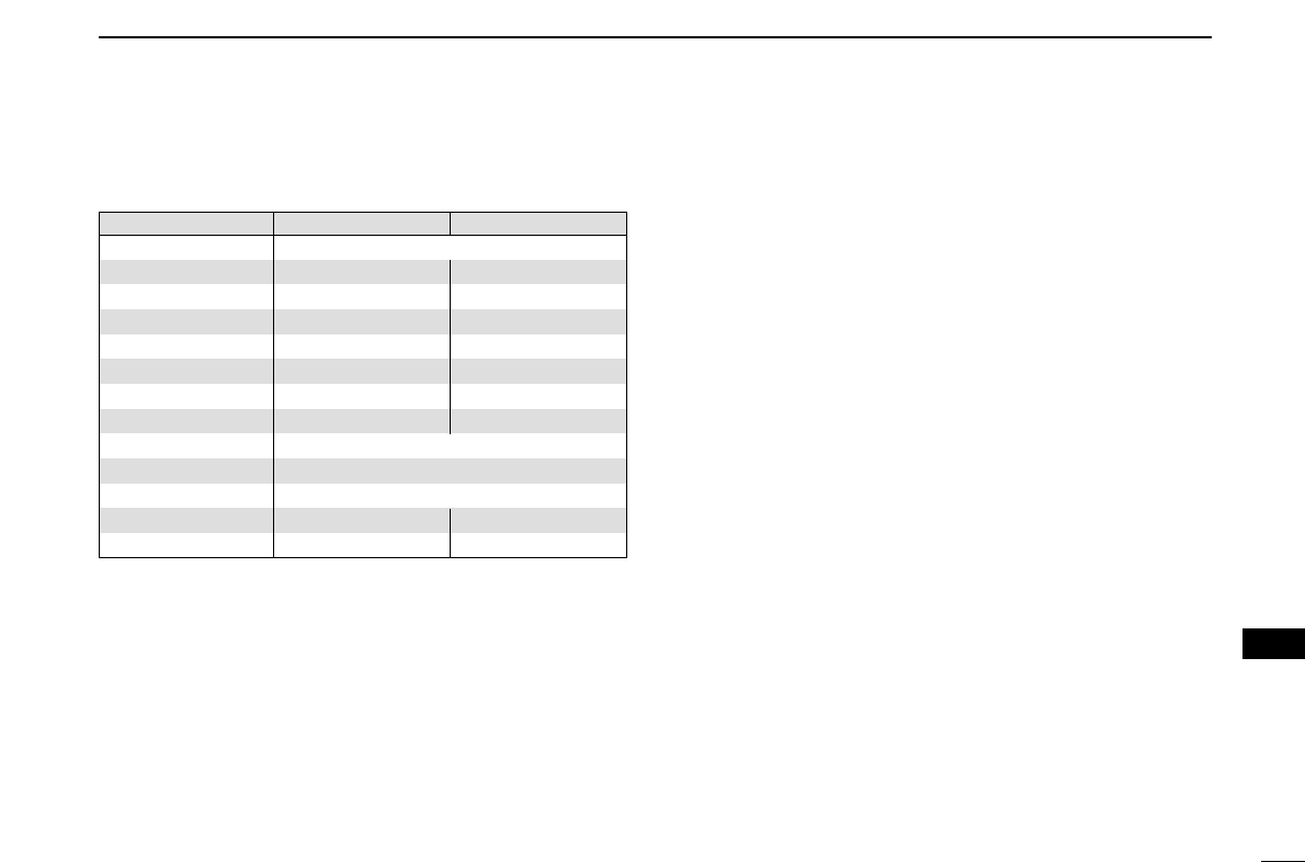
130
14
SPECIFICATIONS AND OPTIONS
1
2
3
4
5
6
7
8
9
10
11
12
13
14
15
16
17
18
19
•Sensitivity (for RX bands; for your reference only):
■Options
HM-133
REMOTE
-
CONTROL MICROPHONE
Remote control microphone with key backlight. Same as that sup-
plied with the transceiver.
HM-154
HAND MICROPHONE
OPC-589
ADAPTER CABLE
For using a
OPC-1663/OPC-1712
SEPARATION CABLES
A ferrite core is supplied with the OPC-1155 for the USA version.
Same as that supplied with the transceiver. 3.5 m (11.5 ft)
OPC-1529R
DATA COMMUNICATION CABLE
Allows you to slow-speed data communication in DV mode and data
cloning operation.
OPC-440/OPC-647
MIC EXTENSION CABLES
OPC-440: 5.0 m (16.4 ft); OPC-647: 2.5 m (8.2 ft)
OPC-441
SPEAKER EXTENSION CABLE
5.0 m (16.4 ft)
SP-10
EXTERNAL SPEAKERS
For all-round mobile operation. Cable length: 1.5 m; 4.9 ft
OPC-347/1132
DC POWER CABLES
OPC-347: 7.0 m (23 ft)
OPC-1132: 3.0 m (9.8 ft) Same as that supplied with the transceiver.
CS-2820
CLONING SOFTWARE
Provides quick and easy programming items, such as memory chan-
nels, set mode contents for local repeater frequencies, via PC’s RS-
232C terminal using with the data communication cable, OPC-1529R.
USB type cloning cable, OPC-478U, also available.
OPC-474
CLONING CABLE
Used for data cloning between transceivers.
Frequency range Left band (µV) Right band (µV)
118–159.995 MHz 0.32/1.0
160–173.995 MHz 0.56/—0.56/—
174–179.995 MHz 0.56/—N/A
180–219.995 MHz 5.6/—N/A
220–224.995 MHz 0.56/1.8 N/A
225–349.995 MHz 5.6/18 N/A
350–359.995 MHz 0.56/1.8 N/A
360–374.995 MHz 5.6/18 N/A
375–399.995 MHz 0.56/1.8
400–499.995 MHz 0.32/—
500–549.995 MHz 0.56/—
810–879.990 MHz N/A 0.79 (1.4 for USA)/—
880–999.990 MHz N/A 1.8 (3.2 for USA)/—

131
MODE ARRANGEMENT
15

132
15
MODE ARRANGEMENT
1
2
3
4
5
6
7
8
9
10
11
12
13
14
15
16
17
18
19

1-1-32 Kamiminami, Hirano-ku, Osaka 547-0003, Japan
A-6124D-1EX
Printed in Japan
©2006 Icom Inc.