ICOM orporated 297900 VHF Mobile Transceiver User Manual manual
ICOM Incorporated VHF Mobile Transceiver manual
UserManual.wiki
>
ICOM orporated
>
297900 User Manual
manual
Navigation menu
Upload a User Manual
Namespaces
Wiki Guide
HTML
PDF
Info
Views
User Manual
Discussion / Help
Navigation
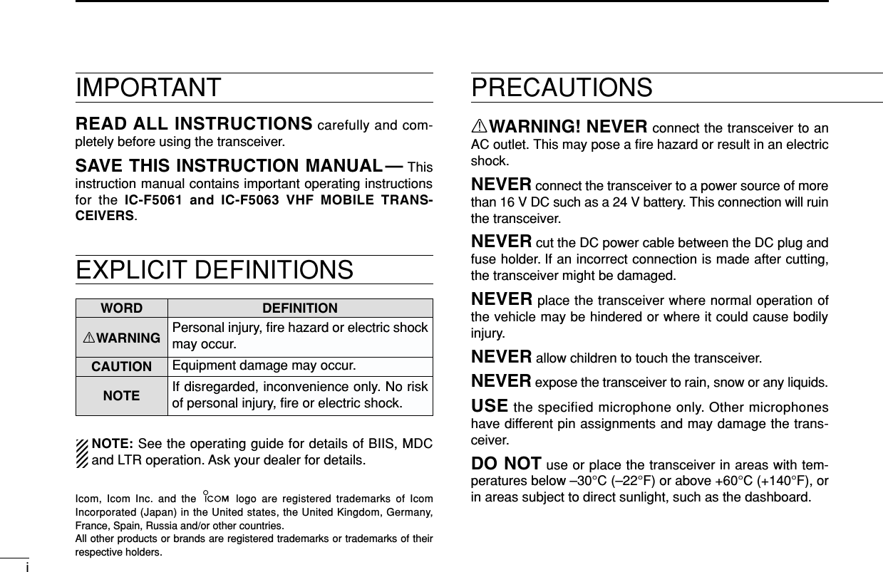
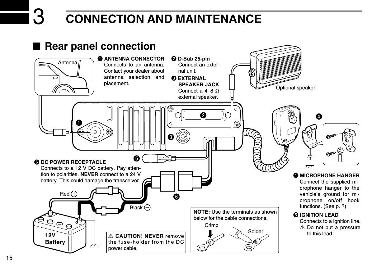
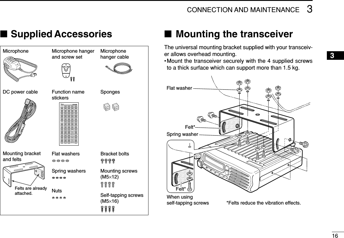
![11PANEL DESCRIPTIONIcom Inc.qeySpeakerFunction display (p. 2)w rt■Front panelqAF VOLUME CONTROL KNOBRotate the knob to adjust the audio output level.• Minimum audio level is pre-programmed.wTRANSMIT INDICATOR➥Lights red while transmitting a signal.➥Lights green while receiving a signal.eUP/DOWN KEYSPush to select an operating channel, etc.*The desired function can be assigned by your dealer. (p. 3)rPOWER SWITCH [POWER]Push to turn the power ON and OFF.• Automatic scan start, Password prompt and Set mode accessare available at power ON.tDEALER-PROGRAMMABLE KEYSDesired functions can be programmed independently byyour dealer. (p. 3)yMICROPHONE CONNECTORConnect the supplied microphone or optional DTMF micro-phone.NEVER connect non-specified microphones. The pinassignments may be different and the transceiver maybe damaged.DDMICROPHONEThe supplied microphone has a PTT switch and a hanger hook.• The following functions are available when the microphone is on oroff hook:- Automatic scan start when on hook.- Automatic priority channel selection when off hook.- Sets to ‘Inaudible’ condition (mute condition) when on hook.- Sets to ‘Audible’ condition (unmute condition) when off hook.](https://usermanual.wiki/ICOM-orporated/297900/User-Guide-761001-Page-4.png)
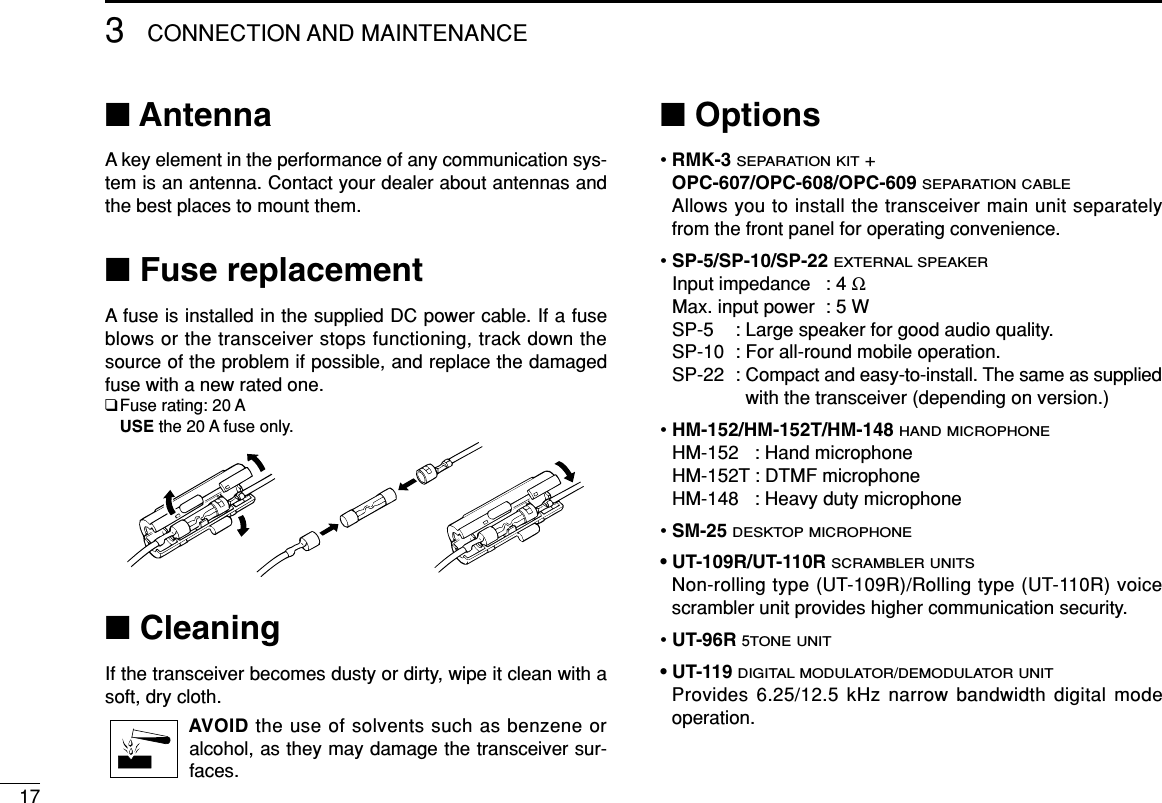
![21PANEL DESCRIPTION12345678910111213141516■Function displayqSIGNAL STRENGTH INDICATORIndicates relative signal strength level.wLOW POWER INDICATORAppears when low output power is selected.eAUDIBLE INDICATOR➥Appears when the channel is in the ‘audible’ (unmute)condition.➥Appears when the specified 2/5-tone/BIIS*1/MDC*2code is received.rCOMPANDER INDICATORAppears when the compander function is activated.tSCRAMBLER INDICATORAppears when the voice scrambler function is activated.yBELL INDICATORAppears/blinks when the specific 2/5-tone/BIIS*1/MDC*2code is received, according to the pre-programming.uCALL CODE MEMORY INDICATOR➥Appears when the call code memory is selected.➥Appears when the DTMF or phone call is received.*3iSDM MEMORY INDICATORAppears when the SDM memory is displayed.*1oSDM INDICATORAppears when an SDM is received, or a transmit SDM isselected.*1!0 ALPHANUMERIC DISPLAYDisplays an operating channel number, channel name, Setmode contents, DTMF code, etc. The indication mode can be selected from 1 line or 2 lines.Ask your dealer for details.In this instruction manual, the LCD illustration is describedusing the 2 lines indication mode.!1 ACTIVATED KEY INDICATORAppears above the key assigned as [Scan A Start/Stop],[Scan B Start/Stop], [Scan Add/Del(Tag)], [Lock], [TalkAround], [Surveillance], [Talkgroup]*4and [DIGITAL]*1keyswhen that keys have been activated.*1BIIS operation only *2MDC operation only*3LTR operation only *4Digital operation onlyNOTE: See the operating guide for details of BIIS, MDCand LTR operation. Ask your dealer for details.Icom Inc.qw ertyuio!0!1](https://usermanual.wiki/ICOM-orporated/297900/User-Guide-761001-Page-5.png)
![31PANEL DESCRIPTION■Programmable function keysThe following functions can be assigned to [UP], [DOWN],[P0], [P1], [P2], [P3] and [P4] programmable function keys.Consult your Icom dealer or system operator for details con-cerning your transceivers programming.If the programmable function names are bracketed in the fol-lowing explanations, the specific key is used to activate thefunction depends on the programming.CH UP AND DOWN KEYS ➥Push to select an operating channel.➥Push to select a transmit code channel after pushing [TXCode CH Select].➥Push to select a DTMF channel after pushing [DTMFAutodial].➥Push to select a scan group after pushing and holding[Scan A Start/Stop]/[Scan B Start/Stop].ZONE KEYPush this key, then select the desired zone using [CH Up]/[CH Down].What is “zone”?—The desired channels are assignedinto a zone according to the intended use for grouping.For example, ‘Staff A’ and ‘Staff B’ are assigned into a“Business” zone, and ‘John’ and ‘Cindy’ are assigned into a“Private” zone.SCAN A START/STOP KEY➥This key’s operation depends on the Power ON Scan setting.When the power ON scan function is turned OFF;Push to start and cancel scanning operation.When the power ON scan function is turned ON;Push to pause scanning, then resumes scanning after aspecified time period has passed.➥Push and hold this key for 1 sec. to indicate the scan group,then select the desired group using [CH Up]/[CH Down].SCAN B START/STOP KEY➥Push to start and cancel scanning operation. Scanresumes after a specified time period has passed whenscan is cancelled except for this key.➥Push and hold this key for 1 sec. to indicate the scan group,then select the desired group using [CH Up]/[CH Down].SCAN ADD/DEL (TAG) KEY➥Push to add or delete the selected channel to/from thescan group.1. Push to indicate the scan group, then push [CH Up] or [CHDown] to select the desired group.2. Push to add or delete the channel to/from the selected scan-ning group.3. Push and hold for 1 sec. to exit the scan group selection mode.➥Push this key while scan is paused (a signal is detected)on a channel (except for priority channel,) the channel iscleared from the scan group.](https://usermanual.wiki/ICOM-orporated/297900/User-Guide-761001-Page-6.png)
![41PANEL DESCRIPTION1Depending on the setting, the cleared channel is addedto the scan group again after the scan is cancelled.PRIO A/B KEYS➥Push to select Priority A or Priority B channel.➥Push and hold [Prio A (Rewrite)] or [Prio B (Rewrite)] torewrite the Priority A or Priority B channel.MR-CH 1/2/3/4 KEYSPush to select an operating channel 1 to 4 directly.MONI (AUDI) KEY➥Mute and release the CTCSS (DTCS) or 2-tone squelchmute. Open any squelch/deactivate any mute while push-ing and holding this key. (LMR operation only)➥Activates one of (or two of) the following functions on eachchannel independently: (PMR or BIIS PMR operation only)• Push and hold to un-mute the channel (audio is emitted;‘Audible’ condition).• Push to mute the channel (sets to ‘Inaudible’ only).• Push to un-mute the channel (sets to ‘Audible’ only).• Push after the communication is finished to send a ‘reset code’.NOTE: The un-mute condition (‘Audible’ condition) mayautomatically return to the mute condition (‘Inaudible‘ con-dition) after a specified period depending on programming.PUBLIC ADDRESS KEYPush to activate the Public Address (PA) function for voiceamplification. When the PA function is activated, the audiooutput can be controlled from the transceiver separately withthe [VOL] control knob.• This function is available when the external unit, such as a audioamplifier, speaker, etc. is additionally connected.•Push this key, then speak into the microphone while pushing andholding [PTT].•[CH Up]/[CH Down] also allow you to set the audio output level.RX SPEAKER KEYThe received audio can be heard via the external speakerwhen this key is pushed.• This function is available when the external speaker is additionallyconnected.•This function is useful when you are out of the vehicle.•The audio output level is linked to the transceiver’s volume control.LIGHT KEYPush to turn the transceiver’s backlight ON for about 5 sec.when the backlight function is turned OFF in user set mode.LOCK KEYPush and hold to electronically lock all programmable keysexcept the following:[Moni(Audi)], [Light], [Lock], [Call] (incl. Call A and Call B),[Emergency Single]/[Emergency Repeat] (incl. Silent), [Surveillance]and [OPT 1/2/3].](https://usermanual.wiki/ICOM-orporated/297900/User-Guide-761001-Page-7.png)
![51PANEL DESCRIPTIONHIGH/LOW KEYPush to select the transmit output power temporarily or per-manently, depending on the pre-setting.•Ask your dealer for the output power level for each selection.C.TONE CH ENT KEYPush to select the continuous tone channel using [CH Up]/ [CHDown] to change the tone frequency/code setting after push-ing this key. The selected channel remains set as the continu-ous tone channel until another channel is designated as such.TALK AROUND KEYPush to turn the talk around function ON and OFF.•The talk around function equalizes the transmit frequency to thereceive frequency for transceiver-to-transceiver communication.WIDE/NARROW KEYPush to toggle the IF bandwidth between wide and narrow.• The wide passband width can be selected from 25.0 or 20.0 kHzusing the CS-F5060 CLONING SOFTWARE. (PMR or BIIS PMR opera-tion only) Ask your Dealer for details.DTMF AUTODIAL KEYPush to enter the DTMF channel selection mode. Then selectthe desired DTMF channel using [CH Up]/[CH Down].After selecting the DTMF channel, push again to transmit theselected DTMF code.RE-DIAL KEYPush to transmit the last-transmitted DTMF code.• TX memories are cleared after turning the transceiver OFF.SCRAMBLER FUNCTIONPush to toggle the voice scrambler function ON and OFF.CALL KEYSPush to transmit a 2/5-tone/BIIS ID code.•Call transmission is necessary before calling another stationdepending on your signalling system.•[Call A] and/or [Call B] may be available when your system employsselective ‘Individual/Group’ calls. Ask your dealer which call isassigned to each key.EMERGENCY KEYS➥Push and hold to transmit an emergency call.➥When [Emergency Single (Silent)] or [Emergency Repeat(Silent)] is pushed, an emergency call is transmitted with-out a beep emission and LCD indication change.• If you want to cancel the emergency call, push (or push andhold) the key again before transmitting the call.• The emergency call is transmitted one time only or repeatedlyuntil receiving a control code depending on the pre-setting.SURVEILLANCE KEYPush to turn the surveillance function ON or OFF.When this function is turned ON, the beep is not emitted andthe LCD backlight does not light when a signal is received ora key is pushed, etc.COMPANDER KEYPush to toggle the compander function ON and OFF. The compander function reduces noise components from thetransmitted audio to provide clear communication.](https://usermanual.wiki/ICOM-orporated/297900/User-Guide-761001-Page-8.png)
![61PANEL DESCRIPTION1TX CODE ENTER KEY (PMR or BIIS PMR operation only)Push to enter the ID code edit mode directly, for both 5-toneand MSK. Then set the desired digit using [CH Up]/[CH Down]. (p. 11)TX CODE CHANNEL SELECT KEY➥Push to enter the ID code channel selection mode directly.Then set the desired channel using [CH Up]/[CH Down]. (p. 10)➥During ID code channel selection mode, push for 1 sec. toenter the ID code edit mode for 5-tone and MSK. Then setthe desired digit using [CH Up]/[CH Down]. (p. 11)TX CODE CHANNEL UP/DOWN KEYS➥Push to select a TX code channel directly.➥Push to set the desired digit during the ID code edit mode.ID-MR SELECT KEY (PMR or BIIS PMR operation only)➥Recalls detected ID codes.• Push this key, then select the ID code using [CH Up]/[CH Down].• Up to 5 ID’s are memorized.➥Push and hold for 1 sec. to erase the selected ID’s.HOOK SCAN KEYWhen the on hook scan function is activated, push this keyto disables on fook scan function (stop scanning) temporarily.Push this key again to re-start scanning.USER SET MODE KEY➥Push and hold to enter user set mode.• During user set mode, push this key to select an item, andchange the value or condition using push [CH Up]/[CH Down].➥Push and hold this key again to exit user set mode.User set mode is also available via the ‘Power ON function.’Refer to p. 14 also.MR-CH ENT KEYSPush to enter the memory channel selection mode, then enterthe desired channel number using the 10-keypad of the con-nected microphone.OPT 1/2/3 KEYSPush to control the output signal level from the optional unitconnector.](https://usermanual.wiki/ICOM-orporated/297900/User-Guide-761001-Page-9.png)
![71PANEL DESCRIPTIONDFor Digital mode operation onlyTALKGROUP KEY➥Push to enter the talkgroup ID code selection mode direct-ly. Then select the desired talkgroup ID code using [CHUp]/[CH Down]. (p. 12)➥Push to stop the beep emission when receiving a matchedtalkgroup ID code.TX STATUS KEYPush to enter the Status message selection mode directly.Then select the desired Status message using [CH Up]/[CHDown]. (p. 12)TONE/RAN CH SELECT KEY➥While in the analog mode operation, push to select thecontinuous tone channel using [CH Up] or [CH Down] tochange the tone frequency/code setting.➥While in the digital mode operation, push to select the RANchannel using [CH Up] or [CH Down] to change the RANcode setting.➥While in the mixed (digital and analog) mode operation,push to select the continuous tone channel using [CH Up]or [CH Down] to change the tone frequency/code setting.Then push this key to enter the setting. After that, the RANchannel selection screen appears. Select the RAN channelusing [CH Up] or [CH Down] to change the RAN code set-ting. Then push this key to enter the setting.](https://usermanual.wiki/ICOM-orporated/297900/User-Guide-761001-Page-10.png)
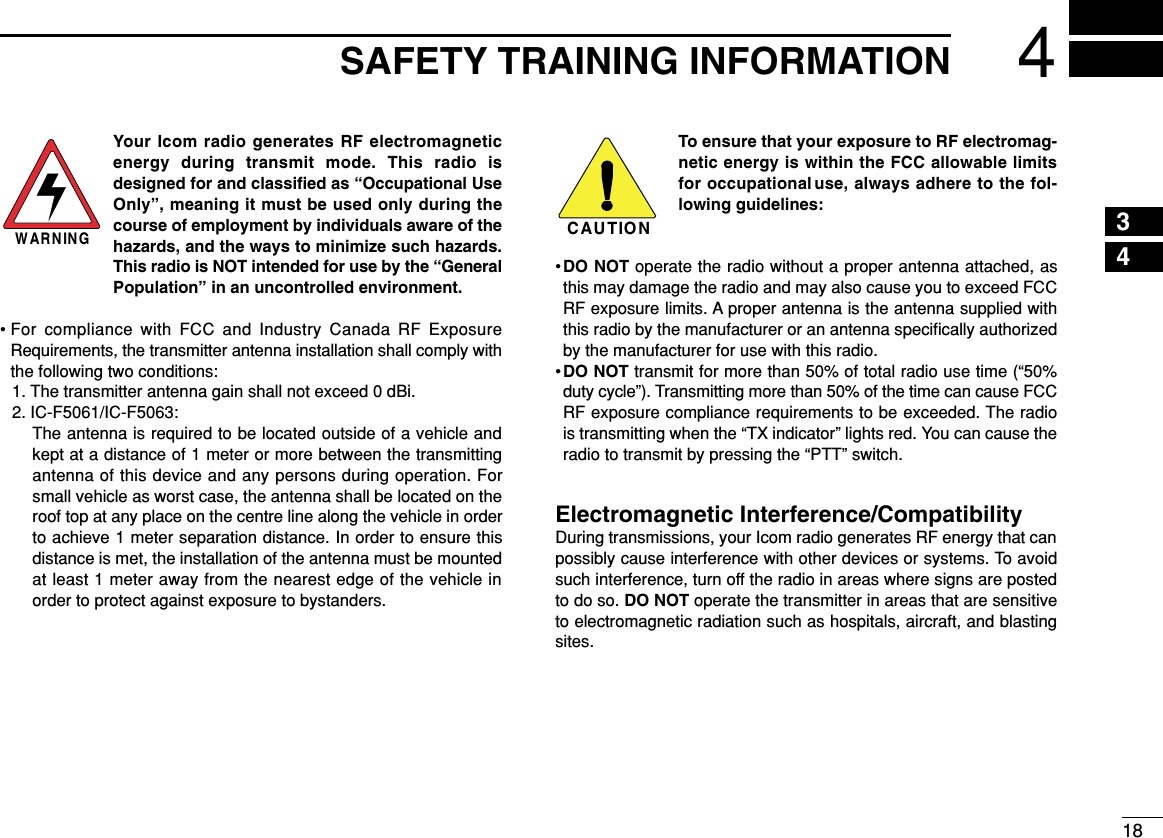
![82BASIC OPERATION12345678910111213141516■Turning power ONqPush []to turn the power ON.wIf the transceiver is programmed for a start up password,input the digit codes as directed by your dealer.• The keys as below can be used for password input:The transceiver detects numbers in the same block as identical.Therefore “01234” and “56789” are the same.eWhen the “PASSWORD” indication does not clear afterinputting 6 digits, the input code number may be incorrect.Turn the power off and start over in this case.■Channel selectionSeveral types of channel selections are available. Methodsmay differ according to your system set up.NON-ZONE TYPE:Push [CH Up] or [CH Down], or rotate [CH Up/Down] to selectthe desired operating channel, in sequence; or, push one of[MR-CH 1] to [MR-CH 4] keys to select a channel directly.ZONE TYPE:Push [Zone] then push [CH Up] or [CH Down], or rotate [ZoneUp/Down] to select the desired zone.AUTOMATIC SCAN TYPE:Channel setting is not necessary for this type. When turningpower ON, the transceiver automatically starts scanning.Scanning stops when receiving a call.KEYNUMBER 0549382716](https://usermanual.wiki/ICOM-orporated/297900/User-Guide-761001-Page-11.png)
![92BASIC OPERATION■Call procedureWhen your system employs tone signaling (excluding CTCSSand DTCS), the call procedure may be necessary prior to voicetransmission. The tone signalling employed may be a selec-tive calling system which allows you to call specific station(s)only and prevent unwanted stations from contacting you.qSelect the desired TX code channel, 2/5-tone code orTalkgroup ID code* according to your System Operator’sinstructions.• This may not be necessary depending on programming.• Refer to pgs. 10–11 for selection.*Digital mode operation only.wPush the call key (assigned to one of the dealer program-mable keys; except for the Digital mode operation) or [PTT].eAfter transmitting, the remainder of your communicationcan be carried out in the normal fashion.■Receiving and transmittingReceiving:qPush [ ] to turn the power ON.wPush [CH Up] or [CH Down] to select a channel, insequence.eWhen receiving a call, adjust the audio output level to acomfortable listening level.Transmitting:Wait for the channel to become clear to avoid interference.qTake the microphone off hook.• 2-tone, 5-tone mute may be released. (The ‘audible’ condition isselected and BUSY indicator lights green.)• A priority channel may be selected automatically.wWait for the channel to become clear.• The channel is busy when BUSY indicator lights green.ePush [CALL] when initiating a call from your side.• Coded audio may be heard from the transceiver, then “ ”appears.• This operation may not be necessary depending on your signal-ing system. Ask your dealer for details.rWhile pushing and holding [PTT], speak into the micro-phone at your normal voice level.tRelease [PTT] to receive.IMPORTANT: To maximize the readability of your signal;1. Pause briefly after pushing [PTT].2. Hold the microphone 5 to 10 cm (2 to 4 inches) fromyour mouth, then speak into the microphone at a normalvoice level.Selective calling Non-selective calling](https://usermanual.wiki/ICOM-orporated/297900/User-Guide-761001-Page-12.png)
![102BASIC OPERATION12345678910111213141516DTransmitting notes• Transmit inhibit functionThe transceiver has several inhibit functions which restricttransmission under the following conditions:- The channel is in mute condition (‘Inaudible’ condition; “ ” does not appear.)- The channel is busy.- Un-matched (or matched) CTCSS is received.(Depending on the pre-setting)- Un-matched (or matched) RAN is received.*(Depending on the pre-setting)- The selected channel is a ‘receive only’ channel.*Digital mode operation only.• Time-out timerAfter continuous transmission for the pre-programmed timeperiod, the time-out timer is activated, causing the transceiv-er to stop transmitting.• Penalty timerOnce the time-out timer is activated, transmission is furtherinhibited for a period determined by the penalty timer.DTX code channel selectionIf the transceiver has [TX Code CH Select] assigned to it, theindication can be toggled between the operating channelnumber (or name) and TX code channel number (or name).When the TX code channel number (or name) is displayed,[CH Up]/[CH Down] selects the TX code channel.USING [TX CODE CH SELECT] KEY:qPush [TX Code CH Select]— a TX code channel number(or name) appears.wPush [CH Up] or [CH Down] to select the desired TX codechannel.ePush [Call] (or [PTT] during MSK operation) to transmit theselected TX code.USING [TX CODE CH UP]/[TX CODE CH DOWN] KEY:If the transceiver has a [TX Code CH Up] or [TX Code CHDown] key assignment, the programmed TX code channelcan be selected directly when pushed.NOTE for PMR or BIIS PMR operation:• The LCD indication does not change when the operatingchannel number (or name) is displayed.• To check the selected TX code, push [TX Code CHSelect].](https://usermanual.wiki/ICOM-orporated/297900/User-Guide-761001-Page-13.png)
![112BASIC OPERATIONDTX code number edit(PMR or BIIS PMR operation only)If the transceiver has [TX Code CH Select] or [TX CodeEnter] assigned to it, TX code contents can be edited withinthe allowable digits.USING [TX CODE CH SELECT] KEY:qPush [TX Code CH Select] to enter the TX code channelselection mode.• Select the desired channel before entering the TX code channelselection mode if necessary.wPush [TX Code CH Select] for 1 sec. to enter the TX codeedit mode.ePush [TX Code CH Select] to select the desired digit to beedited.• The digit to be edited blinks.rPush [CH Up] or [CH Down] to set the desired digit.tPush [TX Code CH Select] to set the digit. The digit to theright will blink automatically.• When the 10-keypad* is used for setting, the digit to the right willblink automatically without pushing [TX Code CH Select].yRepeat rand tto input all allowable digits.uPush [Call] or [PTT] to transmit the edited TX code.USING [TX CODE ENTER] KEY:qSelect the desired TX code channel via [TX Code CHSelect]+[CH Up]/[CH Down], [TX Code CH Up] or [TXCode CH Down].wPush [TX Code Enter] to enter the TX code edit mode.• The digit to be edited blinks.ePush [TX Code Enter] to select the desired digit to be edit-ed.rPush [CH Up] or [CH Down] to set the desired digit.tPush [TX Code Enter] to set the digit. The digit to the rightwill blink automatically.yRepeat rand tto input all allowable digits.uPush [Call] or [PTT] to transmit the edited TX code.](https://usermanual.wiki/ICOM-orporated/297900/User-Guide-761001-Page-14.png)
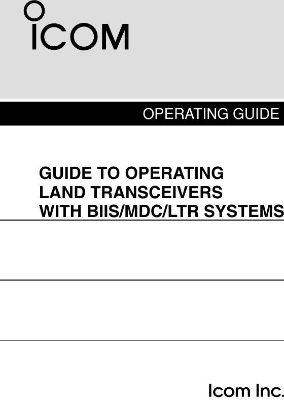
![122BASIC OPERATION2DTalkgroup ID code selection(Digital mode operation only)If the transceiver has [Talkgroup] assigned to it, the indicationcan be toggled between the operating channel name (and thechannel number)* and the Talkgroup ID name (or ID code ifthe ID name is not programmed.) When the Talkgroup IDname (or ID code) is displayed, [CH Up] or [CH Down] selectsthe desired Talkgroup ID name (or ID code).qPush [Talkgroup]— Talkgroup ID name (or ID code)appears.wPush [CH Up] or [CH Down] to select the desiredTalkgroup ID name (or ID code).ePush [PTT] to transmit the selected Talkgroup ID.DTX Status message selection(Digital mode operation only)If the transceiver has [TX Status] assigned to it, the indicationcan be toggled between the operating channel name (and thechannel number)* and the Status message (and the Statuschannel.)* When the Status message (and the Status chan-nel)* is displayed, [CH Up] or [CH Down] selects the desiredStatus message.qPush [TX Status]— Status message (and Status channel)*appears.wPush [CH Up] or [CH Down] to select the desired Statusmessage.ePush [PTT] to transmit the selected Status message.* Only when the 2 lines indication mode is selected.STATUS 01TX Status 01When the 2 lines indication mode is selected.Status messageStatus channelTGID01When the 2 lines indication mode is selectedand [Talkgroup] is assigned to [P0].Talkgroup ID nameAppears above the key that [Talkgroup] is assinged after pushed.](https://usermanual.wiki/ICOM-orporated/297900/User-Guide-761001-Page-15.png)
![132BASIC OPERATIONDDTMF transmissionIf the transceiver has [DTMF Autodial] assigned to it, the auto-matic DTMF transmission function is available. Up to 8 DTMFchannels are available.qPush [DTMF Autodial]— a DTMF channel appears.wPush [CH Up] or [CH Down] to select the desired DTMFchannel.ePush [DTMF Autodial] to transmit the DTMF code in theselected DTMF channel.■Scrambler functionThe voice scrambler function provides private communicationbetween stations. The frequency inversion type is equippedto all versions, moreover, the optional Rolling or Non-rollingtype can be available.qPush [Scrambler] to turn the scrambler function ON.• “ ” appears.wPush [Scrambler] again to turn the scrambler functionOFF.• “ ” disappears.](https://usermanual.wiki/ICOM-orporated/297900/User-Guide-761001-Page-16.png)
![142BASIC OPERATION2■User set modeUser set mode is accessed with [User Set Mode] and allowsyou to set seldom-changed settings. In this case you can“customize” the transceiver operation to suit your preferencesand operating style.Entering the user set mode:qWhile pushing and holding [P1] and [P2], push [ ] to turnthe power ON. Then, push and hold [P0] to enter user setmode.wPush [P0] several times to select the appropriate item.Then, push [Up] or [Down] to set the desired level/condi-tion.• Available set mode functions are Backlight, LCD Contrast,Beep, Beep Level, Ringer Level, SQL Level, AF Min Level,Mic Gain, Horn and Signal Moni.ePush and hold [ ] to turn power OFF, then ON again toexit set mode.User set mode is also available via a programmable key.Please refer to p. 6 [User Set Mode] section.[ ][P0] [Up]/[Down][P1][P0] [P2] [ ]](https://usermanual.wiki/ICOM-orporated/297900/User-Guide-761001-Page-17.png)


![11PREPARATION12345678910111213141516■Programmable function keysThe following functions for MDC 1200 system operation canbe assigned to the programmable function keys;[UP], [DOWN], [P0], [P1], [P2], [P3] and [P4]Consult your Icom dealer or system operator for details con-cerning your transceivers programming.If the programmable function names are bracketed in the fol-lowing explanations, the specific key is used to activate thefunction depends on the programming.DFor BIIS mode operation onlyDIGITAL BUTTON KEY➥Push to select the call ID list, transmit message and stand-by condition. Toggles between queue channel and receivedmessage record indication after queue channel is selected.➥Push and hold to select queue channel indication.STATUS UP/DOWN KEYS➥While in the standby condition, push to display the trans-mit status indication and select a status number.➥When a received SDM is displayed, push to cancel theautomatic scroll and scroll the message manually.➥When an SDM that contains more than 12 characters isdisplayed, push to scroll the message manually.10 KEY ENTER KEYPush to enable the connected microphone’s 10-keypad oper-ation.DFor MDC mode operation onlyMDC CALL KEY➥Push to enter the MDC menu selection mode. Then selectthe desired MDC menu from “SELCALL,” “CALALERT,”“STUN,” “REVIVE,” “RADIOCHK,” “STATUS” and “MSG”using [CH Up], [CH Down], [MDC Up] or [MDC Down].After selection, push this key again to enter the transceiveralias or message channel selection mode.➥While in the transceiver alias or message channel selectionmode, push to return to the MDC menu selection mode.MDC UP AND DOWN KEYS➥Push to select the MDC menu after entering the MD menuselection mode.➥Push to select the desired transceiver alias or messagechannel while in the transceiver alias or message channelselection mode.MDC SELCALL KEYPush to enter the transceiver alias selection mode.• After the desired alias selection, push [PTT] to transmit a SelCall.MDC CALLALERT KEYPush to enter the transceiver alias selection mode.• After the desired alias selection, push [PTT] to transmit a CallAlert.DFor LTR mode operation onlyPHONE KEYPush to connect or disconnect the telephone network con-nection.](https://usermanual.wiki/ICOM-orporated/297900/User-Guide-761001-Page-27.png)
![22BIIS 1200 OPERATION■Default settingThe following functions are assigned to each programmablekey as the default. However, the assigned function can bechanged by your dealer. Ask your dealer for details.NOTE:• During digital mode operation, BIIS 1200 is not available.• [TX Code Enter] must be assigned to a key.[P0]; Call : Push to transmit a 5-tone/BIIS callwhen the selected channel is a 5-tone or MSK channel.[P1]; Digital : Push to select the call list ID/transmitmessage, or to display the receivemessage record for selection.[P3]; TX Code Enter : Push to enter the ID code edit modedirectly for both 5-tone and MSK.[P4]; Moni(Audi) : Push this key after the communica-tion to send a ‘Clear down’ signalduring MSK channel operation.[P2]; Null : No function is assigned.[Up]/[Down]; CH Up/Down: While in the standby condition, pushto select the operating channel.After pushing [Digital] or [TX CodeCH Select], push to select call list orTX code channel, respectively.■Receiving a callDDIndividual callqWhen an individual call is received;• Beeps sound.• “ ” appears and the mute is released.• The programmed text message (e.g.“CALLING”) and the callingstation ID (or text) is displayed when the indication mode is 2lines.• The programmed text message (e.g.“CALLING”) and the callingstation ID (or text) is displayed alternately when the indicationmode is 1 line, depending on the setting.• “ ” appears or blinks depending on the setting.wPush and hold [PTT], then speak into the microphone at anormal voice level.• TX indicator lights red.eRelease [PTT] to return to receive.• BUSY indicator lights green while receiving a signal.rTo finish the conversation, push [P4] (Moni(Audi)) to sendthe ‘Clear down’ signal. • Either station can send a ‘Clear down’ signal.•“CLR DOWN” is displayed for 2 sec. (approx.).• “ ” disappears and the transceiver returns to the standby con-dition.Appears or blinksAppearsCALLING0500](https://usermanual.wiki/ICOM-orporated/297900/User-Guide-761001-Page-28.png)
![32BIIS 1200 OPERATION12345678910111213141516DDGroup callqWhen a group call is received;•Beeps sound.•“ ” appears and the mute is released.•The programmed text message (e.g.“GROUP”) and the calling sta-tion ID (or text) is displayed when the indication mode is 2 lines.•The programmed text message (e.g.“GROUP”) and the callingstation ID (or text) is displayed alternately when the indicationmode is 1 line, depending on the setting.•“ ” appears or blinks depending on the setting.wPush and hold [PTT], then speak into the microphone at anormal voice level.•TX indicator lights red.NOTE: Only one station is permitted to speak.eRelease [PTT] to return to receive.•BUSY indicator lights green while receiving a signal.rTo finish the conversation, push [MONITOR] (Moni(Audi))to send the ‘Clear down’signal.•Either station can send a ‘Clear down’signal.•“CLR DOWN” is displayed for 2 sec. (approx.)•“ ” disappears and the transceiver returns to the standby con-dition.DDDisplaying the received call record— Queue indicationThe transceiver memorizes the calling station ID in the mem-ory. Up to 3 calls can be memorized, and the oldest callrecord is erased when a 4th call is received. However, oncethe transceiver is powered OFF, the all records are cleared.qPush [P1] (Digital) for 1 sec.•Displays following indication.When a record is availableWhen no record is availablewPush [Up] or [Down], or rotate [DIAL] to select the desiredcall.ePush [P1] (Digital) for 1 sec. again to return to the standbycondition.•When no operation is performed for 30 sec., the transceiverreturns to the standby condition automatically.<QUEUE>NO QUEUE<QUEUE>-QUEUE!-Appears or blinksAppearsGROUP1120](https://usermanual.wiki/ICOM-orporated/297900/User-Guide-761001-Page-29.png)
![42BIIS 1200 OPERATION■Transmitting a callA total of 3 ways for code selection are available—selectingthe call code from memory, entering the call code from thekeypad and calling back from the queue channel record.DDUsing call memoryqWhile in the standby condition, push [P1] (Digital) to enterthe call code memory channel selection mode.•“ ” appears.wPush [Up] or [Down], or rotate [DIAL] to select the desiredcall code.ePush [P0] (Call) or [PTT]* to call.*PTT call can be made only when PTT call capability is permitted.NOTE: When no answer back is received, the trans-ceiver repeats the call 3 times (default) automatically,and “WAIT”is displayed during each call. However, anerror beep sounds and “FAILED”is displayed when noanswer back is received after the calls.rPush [PTT] to transmit; release to receive.tPush [P4] (Moni(Audi)) to send the ‘Clear down’signal.DDCalling back from the queue channelqWhile in the standby condition, push [P1] (Digital) for1 sec. to enter the queue memory channel selection mode.wPush [Up] or [Down] or rotate [DIAL] to select the desiredrecord.ePush [P0] (Call) or [PTT]* to call.*PTT call can be made only when PTT call capability is permitted.NOTE: When no answer back is received, the trans-ceiver repeats the call 3 times (default) automatically,and “WAIT”is displayed during each call. However, anerror beep sounds and “FAILED”is displayed when noanswer back is received after the calls.rPush [PTT] to transmit; release to receive.tPush [P4] (Moni(Audi)) to send the ‘Clear down’signal.<QUEUE>-QUEUE!-CALLING0500Appears](https://usermanual.wiki/ICOM-orporated/297900/User-Guide-761001-Page-30.png)
![52BIIS 1200 OPERATION12345678910111213141516DDDirect code entryqWhile in the standby condition, push [P3] (TX Code Enter)to enter the TX code edit mode.•Code digit for editing blinks.wPush [P3] (TX Code Enter) to select the desired digit to beedited.•Digit for editing differs according to the setting.eSet the desired digit using [CH Up]/[CH Down].rPush [P3] (TX Code Enter) to set the digit, then the digitto the right will blink automatically.tRepeat eand rto input all allowable digits.yPush [P0] (Call) or [PTT]* to call.*PTT call can be made only when PTT call capability is permitted.NOTE: When no answer back is received, the trans-ceiver repeats the call 3 times (default) automatically,and “WAIT”is displayed during each call. However, anerror beep sounds and “FAILED”is displayed when noanswer back is received after the calls.uPush [PTT] to transmit; release to receive.iPush [P4] (Moni(Audi)) to send the ‘Clear down’signal.For your informationWhen the “UpDate” setting for the call code is enabled, theset code is overwritten into the call code memory.0500](https://usermanual.wiki/ICOM-orporated/297900/User-Guide-761001-Page-31.png)
![62BIIS 1200 OPERATION■Receiving a messageDDReceiving a status messageqWhen a status message is received;• Beeps sound.• The calling station ID (or text) and the status message is dis-played alternately when the indication mode is 1 line, dependingon the setting.wPush [P4] (Moni(Audi)) to return to the standby condition.NOTE: Only the calling station ID (or text) is displayed (nomessage is displayed alternately) when the scroll timer isset to ‘OFF.’In this case, push [Status Up]/[Status Down]to display the status message manually.DDReceiving an SDM (Short Data Message)qWhen an SDM is received;• Beeps sound.• The calling station ID (or text) and the SDM is displayed alter-nately when the indication mode is 1 line, depending on the set-ting.• “” appearswWhen the received SDM includes more than 12 charac-ters, the message scrolls automatically, when the auto-matic scroll function is activated.• Push [Status Up]/[Status Down] to scroll the message manually.ePush [P4] (Moni(Audi)) to return to the standby condition.SDM12345678BASESDM 8BASEAppearsRX Status 01BASE](https://usermanual.wiki/ICOM-orporated/297900/User-Guide-761001-Page-32.png)
![72BIIS 1200 OPERATION12345678910111213141516DDReceived message selectionThe transceiver memorizes the received message in thememory. Up to 6 messages for status and SDM, or 95 char-acter SDM’s can be memorized. The oldest message iserased when the 7th message is received. However, once thetransceiver is powered OFF, all messages are cleared.qPush [P1] (Digital) for 1 sec.•Displays queue memory.wPush [P1] (Digital) momentarily.•Displays message memory.When a message is availableWhen no message is availableePush [Up] or [Down], or rotate [DIAL] to select the desiredmessage.•When selecting the SDM that includes more than 12 characters,the message scrolls automatically when the automatic scrollfunction is activated.• Push [Status Up]/[Status Down] to scroll the message manually.rPush [P1] (Digital) for 1 sec. again to return to the standbycondition.•When no operation is performed for 30 sec., the transceiverreturns to the standby condition automatically.MESSAGE-NO MSG-MESSAGE-MSG!-](https://usermanual.wiki/ICOM-orporated/297900/User-Guide-761001-Page-33.png)
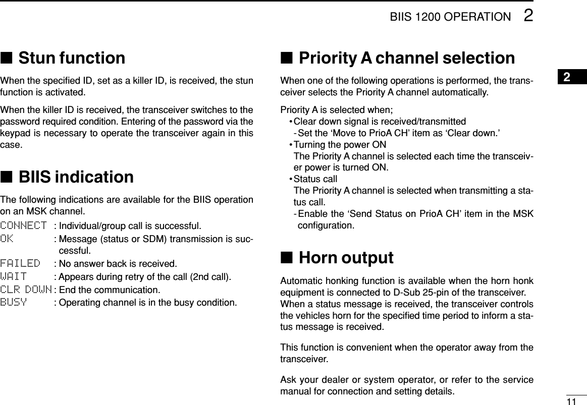
![82BIIS 1200 OPERATION■Transmitting a statusDDGeneralThe status message can be selected with the programmedtext, and the message text is also displayed on the functiondisplay of the called station.Up to 24 status types (1 to 24) are available, and the statusmessages 22 and 24 have designated meanings.Status 22: Emergency*Status 24: GPS request*The status 22 can also be used as a normal status message bydisabling the designated meaning. However, the status 24 is fixed.The status call can be sent with both individual and groupcalls.DDTransmitting a statusqWhile in the standby condition, push [P1] (Digital), thenpush [Up] or [Down], or rotate [DIAL] to select the desiredstation/group code.wPush [P1] (Digital) again, then push [UP] or [DOWN] toselect the desired status message.Or, you can select the desired status message using[Status Up]/[Status Down] key directly.ePush [P0] (Call) or [PTT]* to transmit the status messageto the selected station/group.*PTT call can be made only when PTT call capability is permitted.•2 beeps will sound and the transceiver returns to the standbycondition automatically when the transmission is successful.STATUS 01TX Status 01Status message is displayed.](https://usermanual.wiki/ICOM-orporated/297900/User-Guide-761001-Page-34.png)
![92BIIS 1200 OPERATION12345678910111213141516DDGeneralThe short data message, SDM, can be sent to an individualstation or group stations. Also, 8 SDM memory channels areavailable and the messages can be edited via PC program-ming.DDTransmitting an SDMqWhile in the standby condition, push [P1] (Digital), thenpush [Up] or [Down] or rotate [DIAL] to select the desiredstation/group code.wPush [P1] (Digital) again, then push [Up] or [Down] orrotate [DIAL] to select the desired SDM.Or, you can select the desired SDM using [Status Up]/[Status Down] key directly.ePush [P0] (Call) or [PTT]* to transmit the SDM to theselected station/group.*PTT call can be made only when PTT call capability is permitted.•2 beeps will sound and the transceiver returns to the standbycondition automatically when the transmission is successful.MESSAGE 1SDM 1SDM is displayed.Appears](https://usermanual.wiki/ICOM-orporated/297900/User-Guide-761001-Page-35.png)
![102BIIS 1200 OPERATION■Position data transmissionWhen the optional cable and a GPS receiver is connected tothe transceiver, the position (longitude and latitude) data canbe transmitted automatically.Ask your dealer or system operator for connection details.The position data is transmitted when;•Status 24 message is received*When the status 24 message, GPS request, is received.•Fully automaticWhen automatic position transmission is enabled, sendthe position data according to ‘Time Marker’and ‘IntervalTimer’settings.•PTT is releasedWhen ‘Send with Logoff’is enabled.-Set the ‘Log-In/Off’item as ‘L-OFF.’•After sending a status messageWhen ‘Send with Status’is enabled.•After sending an SDMWhen ‘Send with SDM’is enabled.•After sending status 22 (Emergency)When ‘Send with Emergency’is enabled.■Printer connectionWhen the printer is connected to the D-sub 25-pin of the trans-ceiver, the received SDM content and the ID of the station whosent the message can be printed out. Ask your dealer or sys-tem operator for connection details.■Digital ANIThe own ID can be transmitted each time the PTT is pushed(log-in) or released (log-off) during individual or group callcommunications.By receiving the ANI, the communication log can be recordedwhen using a PC dispatch application.In addition, when using the ANI with log-in, the PTT side tonefunction can be used to inform you that the ID is sent andvoice communication can be performed.■Auto emergency transmissionWhen [Emergency Single (Silent)] or [Emergency Repeat(Silent)] is pushed, an emergency signal is automaticallytransmitted for the specified time period.The status 22 (Emergency) is sent to the selected ID station,and the position data is transmitted after the emergency sig-nal when a GPS receiver is connected to the transceiver.The emergency transmission is performed on the emergencychannel, however, when no emergency channel is specified,the signal is transmitted on the previously selected channel.There is no change in the function display or beep emissionduring automatic emergency transmission.](https://usermanual.wiki/ICOM-orporated/297900/User-Guide-761001-Page-36.png)
![123MDC 1200 OPERATION■MDC 1200 system operationThe MDC 1200 signaling system enhances your transceiver’scapabilities. It allows PTT ID, Selective Calling, CallAlert,Radio Check, Stun, Revive, Status, Messaging andEmergency signaling. Also, the dispatcher can stun andrevive transceivers on the system.An additional feature of MDC 1200 found in Icom transceiversis called aliasing. Each transceiver on the system has aunique ID number. Aliasing allows the substitution of analphanumeric name for this ID number. For transmit, you canuse this alias to select a transceiver to call. For receive, thealias of the calling station is displayed instead of the ID.Please note that your dealer has set one of the programma-ble keys ([UP], [DOWN], [P0], [P1], [P2], [P3] and [P4]) forMDC 1200 operation.NOTE: During digital mode operation, MDC 1200 is notavailable.■Receiving a callDDReceiving a Selective CallqWhen a selective call is received;• Beeps sound.• “” appears.• “” blinks.• The calling station ID (or alias) and “SELCALL” are displayedalternately.wPush and hold [PTT] and speak into the microphone.eRelease [PTT] to receive a response.SELCALLID 1234BlinksAppears](https://usermanual.wiki/ICOM-orporated/297900/User-Guide-761001-Page-38.png)
![133MDC 1200 OPERATION12345678910111213141516DDReceiving a CallAlertqWhen a CallAlert is received;• Beeps sound.• “” blinks.• The calling station ID (or alias) and “CALLALRT” are displayedalternately.wPush and hold [PTT] and speak into the microphone.eRelease [PTT] to receive a response.DDReceiving a Emergency CallqWhen an emergency call is received;• Beeps sound.• The calling station ID (or alias) and “EMG EMG” are displayedalternately until turning power OFF, the channel changing, etc.wWhen the automatic acknowledgement function is turnedON, the transceiver automatically transmits an acknowl-edgement call to the station.• The calling station stops calling.eTurn power OFF, change the channel, etc. to stop the beepand display indication.ID 1234EMG EMGCALLALRTID 1234Blinks](https://usermanual.wiki/ICOM-orporated/297900/User-Guide-761001-Page-39.png)
![143MDC 1200 OPERATIONDDReceiving a MessageqWhen a Message is received;• Beeps sound.• The calling station ID (or alias) and the message are displayedalternately.wTurn power OFF, push [PTT], change the channel, etc. tostop the display indication.DDReceiving a Status Message➥When a Status Message is received;• Beeps sound.• The calling station ID (or alias) and the status message are dis-played once.DDReceiving a Stun or ReviveIf a Stun command is received that matches your station ID,the transceiver will display “SORRY” and you can not receiveor transmit. When a Revive command is received that match-es your station ID, normal operation is restored.ID 1234STATUS1ID 1234MSG 1](https://usermanual.wiki/ICOM-orporated/297900/User-Guide-761001-Page-40.png)
![153MDC 1200 OPERATION12345678910111213141516■Transmitting a callDDTransmitting a Selective CallSelective calling allows you to make a call to a specific stationor to a particular group. Other MDC 1200 transceivers on thechannel will not receive a selective call that does not matchtheir station or group ID’s.qPush [MDC Call] to enter the MDC menu selection mode.• Or push [MDC SelCall] to enter the transceiver alias selectionmode. In this case, skip step w.wPush [MDC Call] again to enter the transceiver alias selec-tion mode.eSelect the desired alias using [CH Up], [CH Down], [MDCUp] or [MDC Down].rPush and hold [PTT] to transmit the selective call to theselected station, then speak into the microphone.• “” appears.tRelease [PTT] to receive.DDTransmitting a CallAlertCallAlert allows you to notify another user who may be awayfrom the transceiver that you want to talk.qPush [MDC Call] to enter the MDC menu selection mode.• Or push [MDC CallAlert] to enter the transceiver alias selectionmode. In this case, skip steps wand e.wSelect “CALALERT” using [CH Up], [CH Down], [MDCUp] or [MDC Down].ePush [MDC Call] again to enter the transceiver alias selec-tion mode.rSelect the desired alias using [CH Up], [CH Down], [MDCUp] or [MDC Down].tPush [PTT] to transmit the CallAlert to the selected station.• “CA CALL” is displayed.yRelease [PTT].• “CA OK” is displayed if the targeted station received the alert.• “CA FAIL” is displayed if the targeted station does not send anacknowledgement.uAfter a specified time period has passed, the transceiverwill return to receive.CALALERTSELCALL](https://usermanual.wiki/ICOM-orporated/297900/User-Guide-761001-Page-41.png)
![163MDC 1200 OPERATIONDDTransmitting a Stun CallStun call allows you to send MDC 1200 signal that will stunthe targeted station.qPush [MDC Call] to enter the MDC menu selection mode.wSelect “STUN” using [CH Up], [CH Down], [MDC Up] or[MDC Down].ePush [MDC Call] again to enter the transceiver alias selec-tion mode.rSelect the desired alias using [CH Up], [CH Down], [MDCUp] or [MDC Down].tPush [PTT] to transmit the stun call to the selected station.• “STN TX” is displayed.yRelease [PTT].• “STN ACK” is displayed if the targeted station is turned ON, onchannel and within range.• “STN FAIL” is displayed if the targeted station does not send anacknowledgement.uAfter a specified time period has passed, the transceiverwill return to receive.DDTransmitting a Revive CallRevive call allows you to send MDC 1200 signals that willrevive the targeted (stunned) station.qPush [MDC Call] to enter the MDC menu selection mode.wSelect “REVIVE” using [CH Up], [CH Down], [MDC Up]or [MDC Down].ePush [MDC Call] again to enter the transceiver alias selec-tion mode.rSelect the desired alias using [CH Up], [CH Down], [MDCUp] or [MDC Down].tPush [PTT] to transmit the revive call to the selected sta-tion.• “REV TX” is displayed.yRelease [PTT].• “REV ACK” is displayed if the targeted station is turned ON, onchannel and within range.• “REV FAIL” is displayed if the targeted station does not send anacknowledgement.uAfter a specified time period has passed, the transceiverwill return to receive.REVIVESTUN](https://usermanual.wiki/ICOM-orporated/297900/User-Guide-761001-Page-42.png)
![173MDC 1200 OPERATION12345678910111213141516DDTransmitting a Radio Check CallRadio check call allows you to determine whether anothertransceiver is turned on, within range and on channel withoutrequiring any action from the targeted station user.qPush [MDC Call] to enter the MDC menu selection mode.wSelect “RADIOCHK” using [CH Up], [CH Down], [MDCUp] or [MDC Down].ePush [MDC Call] again to enter the transceiver alias selec-tion mode.rSelect the desired alias using [CH Up], [CH Down], [MDCUp] or [MDC Down].tPush [PTT] to transmit the radio check call to the selectedstation.• “RDO CHK” is displayed.yRelease [PTT].• “CHK ACK” is displayed if the targeted station is turned ON, onchannel and within range.• “CHK FAIL” is displayed if the targeted station does not send anacknowledgement.uAfter a specified time period has passed, the transceiverwill return to receive.DDTransmitting a Status MessageStatus Messaging allows you to send a pre-programmed sta-tus message. There are 16 status codes that can be sent. Inaddition, the dispatcher can send an MDC 1200 signal thatcauses the transceiver to automatically transmit its currentstatus.qPush [MDC Call] to enter the MDC menu selection mode.wSelect “STATUS” using [CH Up], [CH Down], [MDC Up]or [MDC Down].ePush [MDC Call] again to enter the status message selec-tion mode.rSelect the desired status message using [CH Up], [CHDown], [MDC Up] or [MDC Down].tPush [PTT] to transmit the selected status message.• “STAT TX” is displayed.yRelease [PTT].• “STAT OK” is displayed.• “STA FAIL” is displayed if there is no acknowledgment from thedispatcher.uAfter a specified time period has passed, the transceiverwill return to receive.STATUSSTATUS1Pre-programmed status message is displayed.STATUSRADIOCHK](https://usermanual.wiki/ICOM-orporated/297900/User-Guide-761001-Page-43.png)
![183MDC 1200 OPERATIONDDTransmitting a MessageThe transceiver can send a pre-programmed message. Thereare 16 messages that can be sent on a channel.qPush [MDC Call] to enter the MDC menu selection mode.wSelect “MSG” using [CH Up], [CH Down], [MDC Up] or[MDC Down].ePush [MDC Call] again to enter the pre-programmed mes-sage selection mode.rSelect the desired message using [CH Up], [CH Down],[MDC Up] or [MDC Down].tPush [PTT] to transmit the selected message.• “MSG TX” is displayed.yRelease [PTT].• “MSG OK” is displayed.• “MSG FAIL” is displayed if there is no acknowledgment from thedispatcher.uAfter a specified time period has passed, the transceiverwill return to receive.MSGMSG 1Pre-programmed message is displayed.MSG](https://usermanual.wiki/ICOM-orporated/297900/User-Guide-761001-Page-44.png)
![193MDC 1200 OPERATION12345678910111213141516DDPTTID CallsThe transceiver can send an MDC 1200 signal that includesPTTID when [PTT] is pushed (beginning of transmission) andreleased (end of transmission). If a PTTID call is received, thetransceiver will display the calling station ID (or alias) andemit a beep*.*Depends on the setting.DDEmergency CallsThe MDC 1200 Emergency feature can be accessed usingthe [Emergency Single] or [Emergency Repeat] key(described in the instruction manual). The transceiver willrepeatedly send an Emergency MDC 1200 command for aprogrammed length of time until it receives an acknowledge-ment signal.The emergency call can be transmitted without a beep emis-sion and LCD indication change depends on the setting.With MDC 1200 Emergency, the transceiver can also be pro-grammed to keep the microphone open during an emergencycall, allowing monitoring of the situation.Ask your dealer for details.](https://usermanual.wiki/ICOM-orporated/297900/User-Guide-761001-Page-45.png)
![204LTR OPERATION■Receiving a callDGroup callqPush [CH Up] or [CH Down] to select the LTR systemchannel or talk group.wWhen a call is received;•‘BUSY’indicator lights green.ePush and hold [PTT], then speak into the microphone at anormal voice level.rRelease [PTT] to return to receive.DSelective call (DTMF call)qPush [CH Up] or [CH Down] to select the LTR systemchannel or talk group.wPush [Call] to mute the channel.eWhen receiving a call, the calling station name appearsand a beep is emitted. Then the mute is released.•“ ” appears.DPhone callqPush [CH Up] or [CH Down] to select the phone channel ofLTR system channel.•“ ” appears.wWhen a phone call is received (transceiver rings), push[Phone] (or push [PTT]).•“ ” blinks.ePush and hold [PTT], then speak into the microphone at anormal voice level. Release [PTT] to return to receive.rAfter conversation is finished, push [Phone] to disconnectthe phone call.•“ ” stops blinking.002 ch-03fH 173.7MBlinks002 ch-03fH 173.7MAppears](https://usermanual.wiki/ICOM-orporated/297900/User-Guide-761001-Page-46.png)
![214LTR OPERATION12345678910111213141516■Transmitting a callDGroup callqPush [CH Up] or [CH Down] to select the LTR systemchannel or talk group.wWhile pushing and holding [PTT], speak into the micro-phone at a normal voice level after a beep is emitted.• If an error beep is emitted, release [PTT]. After a while, repeatstep w.• The beep can be turned OFF in User set mode.DSelective call (DTMF call)qPush [CH Up] or [CH Down] to select the LTR systemchannel or talk group.wPush [DTMF Autodial]— a DTMF encode channelappears.ePush [CH Up] or [CH Down] to select the desired DTMFencode channel.rPush [PTT] to transmit the selected DTMF code in theselected DTMF channel.• Push [DTMF Autodial] to cancel the DTMF transmission.DPhone callqSelect the phone channel of LTR system channel.•“ ” appears.wPush [Phone] (or push [PTT]).•“ ” blinks.ePush [DTMF Autodial] to make a phone call.rAfter conversation is finished, push [Phone] to disconnectthe phone call.•“ ” stops blinking.002 ch-03fH 173.7MBlinks](https://usermanual.wiki/ICOM-orporated/297900/User-Guide-761001-Page-47.png)