ICOM orporated 297900 VHF Mobile Transceiver User Manual manual
ICOM Incorporated VHF Mobile Transceiver manual
manual
INSTRUCTION MANUAL
VHF MOBILE TRANSCEIVER
iF5063
iF5061

i
EXPLICIT DEFINITIONS
RWARNING! NEVER connect the transceiver to an
AC outlet. This may pose a fire hazard or result in an electric
shock.
NEVER connect the transceiver to a power source of more
than 16 V DC such as a 24 V battery. This connection will ruin
the transceiver.
NEVER cut the DC power cable between the DC plug and
fuse holder. If an incorrect connection is made after cutting,
the transceiver might be damaged.
NEVER place the transceiver where normal operation of
the vehicle may be hindered or where it could cause bodily
injury.
NEVER allow children to touch the transceiver.
NEVER expose the transceiver to rain, snow or any liquids.
USE the specified microphone only. Other microphones
have different pin assignments and may damage the trans-
ceiver.
DO NOT use or place the transceiver in areas with tem-
peratures below –30°C (–22°F) or above +60°C (+140°F), or
in areas subject to direct sunlight, such as the dashboard.
PRECAUTIONS
WORD DEFINITION
RWARNING Personal injury, fire hazard or electric shock
may occur.
CAUTION Equipment damage may occur.
NOTE If disregarded, inconvenience only. No risk
of personal injury, fire or electric shock.
READ ALL INSTRUCTIONS carefully and com-
pletely before using the transceiver.
SAVE THIS INSTRUCTION MANUAL— This
instruction manual contains important operating instructions
for the IC-F5061 and IC-F5063 VHF MOBILE TRANS-
CEIVERS.
IMPORTANT
Icom, Icom Inc. and the logo are registered trademarks of Icom
Incorporated (Japan) in the United states, the United Kingdom, Germany,
France, Spain, Russia and/or other countries.
All other products or brands are registered trademarks or trademarks of their
respective holders.
NOTE: See the operating guide for details of BIIS, MDC
and LTR operation. Ask your dealer for details.

ii
AVOID operating the transceiver without running the vehi-
cle’s engine. The vehicle’s battery will quickly run out if the
transceiver transmits while the vehicle’s engine OFF.
AVOID placing the transceiver in excessively dusty envi-
ronments.
AVOID placing the transceiver against walls. This will
obstruct heat dissipation.
AVOID the use of chemical agents such as benzine or
alcohol when cleaning, as they damage the transceiver sur-
faces.
BE CAREFUL! The transceiver will become hot when
operating continuously for long periods.
For U.S.A. only
CAUTION: Changes or modifications to this transceiver, not ex-
pressly approved by Icom Inc., could void your authority to operate
this transceiver under FCC regulations.
TABLE OF CONTENTS
IMPORTANT .................................................................................... i
EXPLICIT DEFINITIONS ................................................................. i
PRECAUTIONS ............................................................................... i
TABLE OF CONTENTS .................................................................. ii
1 PANEL DESCRIPTION ........................................................... 1–7
■Front panel ............................................................................... 1
■Function display ....................................................................... 2
■Programmable function keys ................................................... 3
2 BASIC OPERATION ............................................................. 8–13
■Turning power ON .................................................................... 8
■Channel selection .................................................................... 8
■Call procedure .......................................................................... 9
■Receiving and transmitting ....................................................... 9
DTransmitting notes ............................................................... 10
DTX code channel selection .................................................. 10
DTX code number edit............................................................ 11
DTalkgroup ID code selection ................................................ 12
DTX Status message selection .............................................. 12
DDTMF transmission ............................................................. 12
■Scrambler function ................................................................. 13
■User set mode ........................................................................ 13
3 CONNECTION AND MAINTENANCE ................................ 15–17
■Rear panel connection ........................................................... 15
■Supplied Accessories ............................................................. 16
■Mounting the transceiver......................................................... 16
■Antenna................................................................................... 17
■Fuse replacement .................................................................. 17
■Cleaning ................................................................................. 17
■Options ................................................................................... 17
4 SAFETY TRAINING INFORMATION ........................................ 18
1
1PANEL DESCRIPTION
Icom Inc.
qe
y
SpeakerFunction display (p. 2)
w r
t
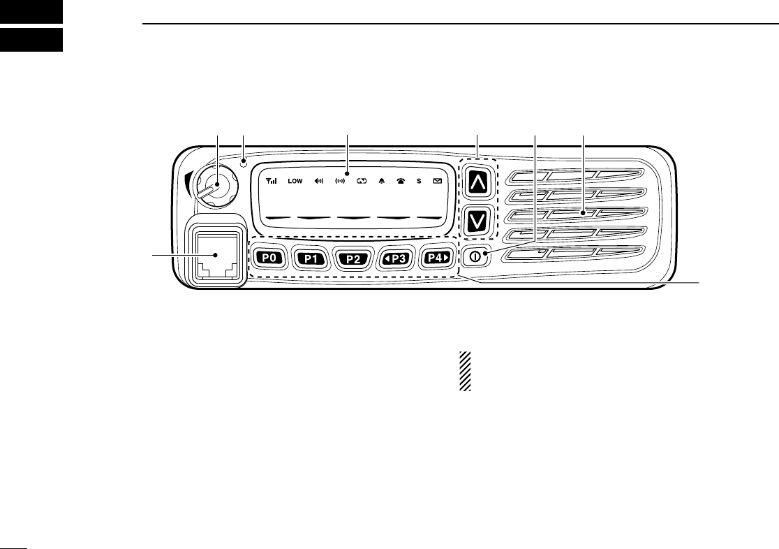
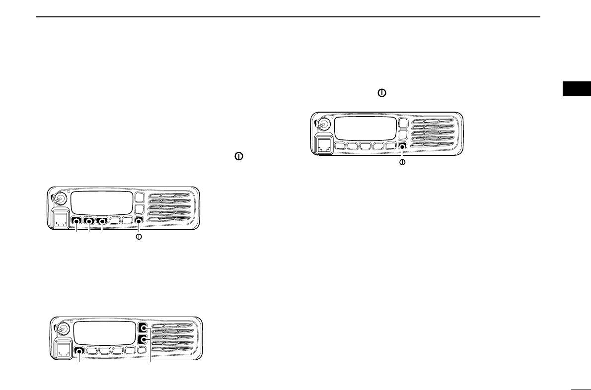
■Front panel
qAF VOLUME CONTROL KNOB
Rotate the knob to adjust the audio output level.
• Minimum audio level is pre-programmed.
wTRANSMIT INDICATOR
➥Lights red while transmitting a signal.
➥Lights green while receiving a signal.
eUP/DOWN KEYS
Push to select an operating channel, etc.
*The desired function can be assigned by your dealer. (p. 3)
rPOWER SWITCH [POWER]
Push to turn the power ON and OFF.
• Automatic scan start, Password prompt and Set mode access
are available at power ON.
tDEALER-PROGRAMMABLE KEYS
Desired functions can be programmed independently by
your dealer. (p. 3)
yMICROPHONE CONNECTOR
Connect the supplied microphone or optional DTMF micro-
phone.
NEVER connect non-specified microphones. The pin
assignments may be different and the transceiver may
be damaged.
DDMICROPHONE
The supplied microphone has a PTT switch and a hanger hook.
• The following functions are available when the microphone is on or
off hook:
- Automatic scan start when on hook.
- Automatic priority channel selection when off hook.
- Sets to ‘Inaudible’ condition (mute condition) when on hook.
- Sets to ‘Audible’ condition (unmute condition) when off hook.
2
1
PANEL DESCRIPTION
1
2
3
4
5
6
7
8
9
10
11
12
13
14
15
16
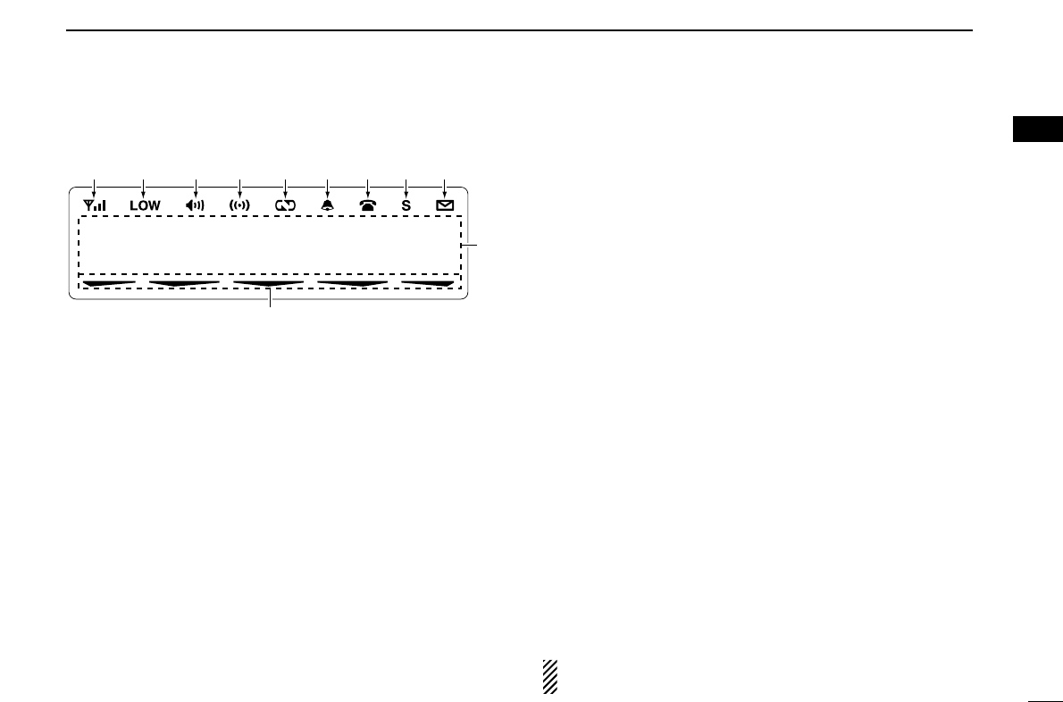
■Function display
qSIGNAL STRENGTH INDICATOR
Indicates relative signal strength level.
wLOW POWER INDICATOR
Appears when low output power is selected.
eAUDIBLE INDICATOR
➥Appears when the channel is in the ‘audible’ (unmute)
condition.
➥Appears when the specified 2/5-tone/BIIS*1/MDC*2
code is received.
rCOMPANDER INDICATOR
Appears when the compander function is activated.
tSCRAMBLER INDICATOR
Appears when the voice scrambler function is activated.
yBELL INDICATOR
Appears/blinks when the specific 2/5-tone/BIIS*1/MDC*2
code is received, according to the pre-programming.
uCALL CODE MEMORY INDICATOR
➥Appears when the call code memory is selected.
➥Appears when the DTMF or phone call is received.*3
iSDM MEMORY INDICATOR
Appears when the SDM memory is displayed.*1
oSDM INDICATOR
Appears when an SDM is received, or a transmit SDM is
selected.*1
!0 ALPHANUMERIC DISPLAY
Displays an operating channel number, channel name, Set
mode contents, DTMF code, etc.
The indication mode can be selected from 1 line or 2 lines.
Ask your dealer for details.
In this instruction manual, the LCD illustration is described
using the 2 lines indication mode.
!1 ACTIVATED KEY INDICATOR
Appears above the key assigned as [Scan A Start/Stop],
[Scan B Start/Stop], [Scan Add/Del(Tag)], [Lock], [Talk
Around], [Surveillance], [Talkgroup]*4and [DIGITAL]*1keys
when that keys have been activated.
*1BIIS operation only *2MDC operation only
*3LTR operation only *4Digital operation only
NOTE: See the operating guide for details of BIIS, MDC
and LTR operation. Ask your dealer for details.
Icom Inc.
qw ertyuio
!0
!1

3
1PANEL DESCRIPTION
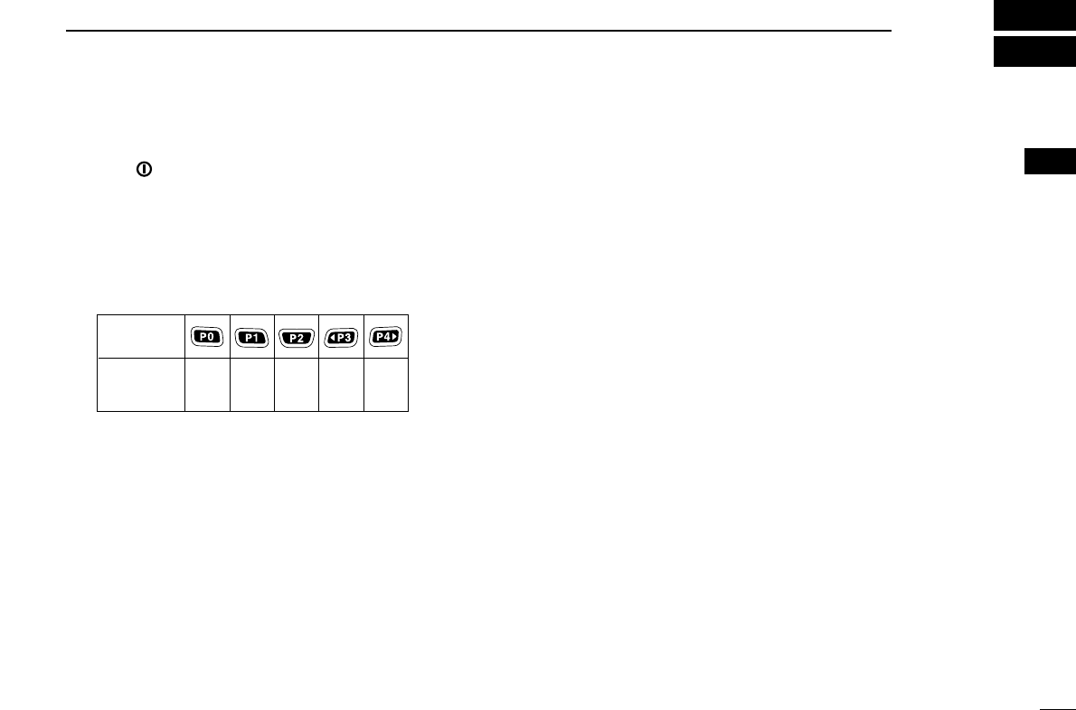
■Programmable function keys
The following functions can be assigned to [UP], [DOWN],
[P0], [P1], [P2], [P3] and [P4] programmable function keys.
Consult your Icom dealer or system operator for details con-
cerning your transceivers programming.
If the programmable function names are bracketed in the fol-
lowing explanations, the specific key is used to activate the
function depends on the programming.
CH UP AND DOWN KEYS
➥Push to select an operating channel.
➥Push to select a transmit code channel after pushing [TX
Code CH Select].
➥Push to select a DTMF channel after pushing [DTMF
Autodial].
➥Push to select a scan group after pushing and holding
[Scan A Start/Stop]/[Scan B Start/Stop].
ZONE KEY
Push this key, then select the desired zone using [CH Up]/
[CH Down].
What is “zone”?—The desired channels are assigned
into a zone according to the intended use for grouping.
For example, ‘Staff A’ and ‘Staff B’ are assigned into a
“Business” zone, and ‘John’ and ‘Cindy’ are assigned into a
“Private” zone.
SCAN A START/STOP KEY
➥This key’s operation depends on the Power ON Scan setting.
When the power ON scan function is turned OFF;
Push to start and cancel scanning operation.
When the power ON scan function is turned ON;
Push to pause scanning, then resumes scanning after a
specified time period has passed.
➥Push and hold this key for 1 sec. to indicate the scan group,
then select the desired group using [CH Up]/[CH Down].
SCAN B START/STOP KEY
➥Push to start and cancel scanning operation. Scan
resumes after a specified time period has passed when
scan is cancelled except for this key.
➥Push and hold this key for 1 sec. to indicate the scan group,
then select the desired group using [CH Up]/[CH Down].
SCAN ADD/DEL (TAG) KEY
➥Push to add or delete the selected channel to/from the
scan group.
1. Push to indicate the scan group, then push [CH Up] or [CH
Down] to select the desired group.
2. Push to add or delete the channel to/from the selected scan-
ning group.
3. Push and hold for 1 sec. to exit the scan group selection mode.
➥Push this key while scan is paused (a signal is detected)
on a channel (except for priority channel,) the channel is
cleared from the scan group.

4
1
PANEL DESCRIPTION
1
Depending on the setting, the cleared channel is added
to the scan group again after the scan is cancelled.
PRIO A/B KEYS
➥Push to select Priority A or Priority B channel.
➥Push and hold [Prio A (Rewrite)] or [Prio B (Rewrite)] to
rewrite the Priority A or Priority B channel.
MR-CH 1/2/3/4 KEYS
Push to select an operating channel 1 to 4 directly.
MONI (AUDI) KEY
➥Mute and release the CTCSS (DTCS) or 2-tone squelch
mute. Open any squelch/deactivate any mute while push-
ing and holding this key. (LMR operation only)
➥Activates one of (or two of) the following functions on each
channel independently: (PMR or BIIS PMR operation only)
• Push and hold to un-mute the channel (audio is emitted;
‘Audible’ condition).
• Push to mute the channel (sets to ‘Inaudible’ only).
• Push to un-mute the channel (sets to ‘Audible’ only).
• Push after the communication is finished to send a ‘reset code’.
NOTE: The un-mute condition (‘Audible’ condition) may
automatically return to the mute condition (‘Inaudible‘ con-
dition) after a specified period depending on programming.
PUBLIC ADDRESS KEY
Push to activate the Public Address (PA) function for voice
amplification. When the PA function is activated, the audio
output can be controlled from the transceiver separately with
the [VOL] control knob.
• This function is available when the external unit, such as a audio
amplifier, speaker, etc. is additionally connected.
•Push this key, then speak into the microphone while pushing and
holding [PTT].
•[CH Up]/[CH Down] also allow you to set the audio output level.
RX SPEAKER KEY
The received audio can be heard via the external speaker
when this key is pushed.
• This function is available when the external speaker is additionally
connected.
•This function is useful when you are out of the vehicle.
•The audio output level is linked to the transceiver’s volume control.
LIGHT KEY
Push to turn the transceiver’s backlight ON for about 5 sec.
when the backlight function is turned OFF in user set mode.
LOCK KEY
Push and hold to electronically lock all programmable keys
except the following:
[Moni(Audi)], [Light], [Lock], [Call] (incl. Call A and Call B),
[Emergency Single]/[Emergency Repeat] (incl. Silent), [Surveillance]
and [OPT 1/2/3].

5
1PANEL DESCRIPTION
HIGH/LOW KEY
Push to select the transmit output power temporarily or per-
manently, depending on the pre-setting.
•Ask your dealer for the output power level for each selection.
C.TONE CH ENT KEY
Push to select the continuous tone channel using [CH Up]/ [CH
Down] to change the tone frequency/code setting after push-
ing this key. The selected channel remains set as the continu-
ous tone channel until another channel is designated as such.
TALK AROUND KEY
Push to turn the talk around function ON and OFF.
•The talk around function equalizes the transmit frequency to the
receive frequency for transceiver-to-transceiver communication.
WIDE/NARROW KEY
Push to toggle the IF bandwidth between wide and narrow.
• The wide passband width can be selected from 25.0 or 20.0 kHz
using the CS-F5060
CLONING SOFTWARE
. (PMR or BIIS PMR opera-
tion only) Ask your Dealer for details.
DTMF AUTODIAL KEY
Push to enter the DTMF channel selection mode. Then select
the desired DTMF channel using [CH Up]/[CH Down].
After selecting the DTMF channel, push again to transmit the
selected DTMF code.
RE-DIAL KEY
Push to transmit the last-transmitted DTMF code.
• TX memories are cleared after turning the transceiver OFF.
SCRAMBLER FUNCTION
Push to toggle the voice scrambler function ON and OFF.
CALL KEYS
Push to transmit a 2/5-tone/BIIS ID code.
•Call transmission is necessary before calling another station
depending on your signalling system.
•[Call A] and/or [Call B] may be available when your system employs
selective ‘Individual/Group’ calls. Ask your dealer which call is
assigned to each key.
EMERGENCY KEYS
➥Push and hold to transmit an emergency call.
➥When [Emergency Single (Silent)] or [Emergency Repeat
(Silent)] is pushed, an emergency call is transmitted with-
out a beep emission and LCD indication change.
• If you want to cancel the emergency call, push (or push and
hold) the key again before transmitting the call.
• The emergency call is transmitted one time only or repeatedly
until receiving a control code depending on the pre-setting.
SURVEILLANCE KEY
Push to turn the surveillance function ON or OFF.
When this function is turned ON, the beep is not emitted and
the LCD backlight does not light when a signal is received or
a key is pushed, etc.
COMPANDER KEY
Push to toggle the compander function ON and OFF.
The compander function reduces noise components from the
transmitted audio to provide clear communication.

6
1
PANEL DESCRIPTION
1
TX CODE ENTER KEY (PMR or BIIS PMR operation only)
Push to enter the ID code edit mode directly, for both 5-tone
and MSK. Then set the desired digit using [CH Up]/
[CH Down]. (p. 11)
TX CODE CHANNEL SELECT KEY
➥Push to enter the ID code channel selection mode directly.
Then set the desired channel using [CH Up]/[CH Down].
(p. 10)
➥During ID code channel selection mode, push for 1 sec. to
enter the ID code edit mode for 5-tone and MSK. Then set
the desired digit using [CH Up]/[CH Down]. (p. 11)
TX CODE CHANNEL UP/DOWN KEYS
➥Push to select a TX code channel directly.
➥Push to set the desired digit during the ID code edit mode.
ID-MR SELECT KEY (PMR or BIIS PMR operation only)
➥Recalls detected ID codes.
• Push this key, then select the ID code using [CH Up]/[CH Down].
• Up to 5 ID’s are memorized.
➥Push and hold for 1 sec. to erase the selected ID’s.
HOOK SCAN KEY
When the on hook scan function is activated, push this key
to disables on fook scan function (stop scanning) temporarily.
Push this key again to re-start scanning.
USER SET MODE KEY
➥Push and hold to enter user set mode.
• During user set mode, push this key to select an item, and
change the value or condition using push [CH Up]/[CH Down].
➥Push and hold this key again to exit user set mode.
User set mode is also available via the ‘Power ON function.’
Refer to p. 14 also.
MR-CH ENT KEYS
Push to enter the memory channel selection mode, then enter
the desired channel number using the 10-keypad of the con-
nected microphone.
OPT 1/2/3 KEYS
Push to control the output signal level from the optional unit
connector.

7
1PANEL DESCRIPTION
DFor Digital mode operation only
TALKGROUP KEY
➥Push to enter the talkgroup ID code selection mode direct-
ly. Then select the desired talkgroup ID code using [CH
Up]/[CH Down]. (p. 12)
➥Push to stop the beep emission when receiving a matched
talkgroup ID code.
TX STATUS KEY
Push to enter the Status message selection mode directly.
Then select the desired Status message using [CH Up]/[CH
Down]. (p. 12)
TONE/RAN CH SELECT KEY
➥While in the analog mode operation, push to select the
continuous tone channel using [CH Up] or [CH Down] to
change the tone frequency/code setting.
➥While in the digital mode operation, push to select the RAN
channel using [CH Up] or [CH Down] to change the RAN
code setting.
➥While in the mixed (digital and analog) mode operation,
push to select the continuous tone channel using [CH Up]
or [CH Down] to change the tone frequency/code setting.
Then push this key to enter the setting. After that, the RAN
channel selection screen appears. Select the RAN channel
using [CH Up] or [CH Down] to change the RAN code set-
ting. Then push this key to enter the setting.
8
2
BASIC OPERATION
1
2
3
4
5
6
7
8
9
10
11
12
13
14
15
16
■Turning power ON
qPush []to turn the power ON.
wIf the transceiver is programmed for a start up password,
input the digit codes as directed by your dealer.
• The keys as below can be used for password input:
The transceiver detects numbers in the same block as identical.
Therefore “01234” and “56789” are the same.
eWhen the “PASSWORD” indication does not clear after
inputting 6 digits, the input code number may be incorrect.
Turn the power off and start over in this case.
■Channel selection
Several types of channel selections are available. Methods
may differ according to your system set up.
NON-ZONE TYPE:
Push [CH Up] or [CH Down], or rotate [CH Up/Down] to select
the desired operating channel, in sequence; or, push one of
[MR-CH 1] to [MR-CH 4] keys to select a channel directly.
ZONE TYPE:
Push [Zone] then push [CH Up] or [CH Down], or rotate [Zone
Up/Down] to select the desired zone.
AUTOMATIC SCAN TYPE:
Channel setting is not necessary for this type. When turning
power ON, the transceiver automatically starts scanning.
Scanning stops when receiving a call.
KEY
NUMBER 0
5
4
9
3
8
2
7
1
6
9
2BASIC OPERATION
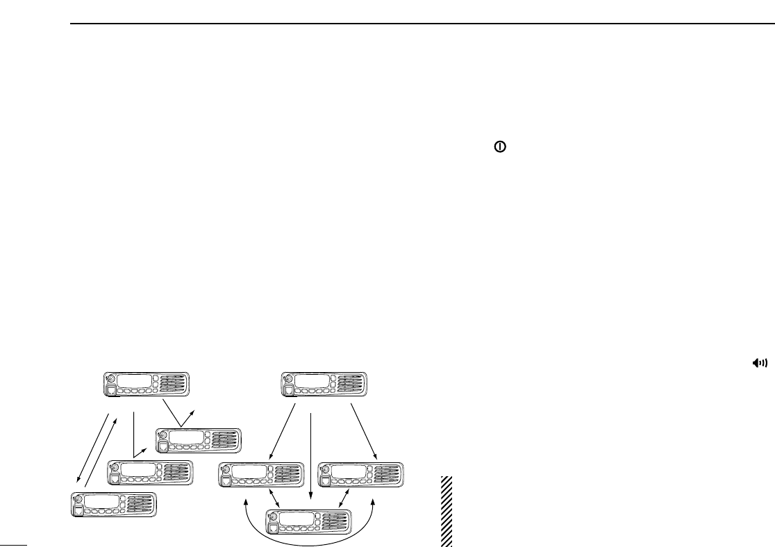
■Call procedure
When your system employs tone signaling (excluding CTCSS
and DTCS), the call procedure may be necessary prior to voice
transmission. The tone signalling employed may be a selec-
tive calling system which allows you to call specific station(s)
only and prevent unwanted stations from contacting you.
qSelect the desired TX code channel, 2/5-tone code or
Talkgroup ID code* according to your System Operator’s
instructions.
• This may not be necessary depending on programming.
• Refer to pgs. 10–11 for selection.
*Digital mode operation only.
wPush the call key (assigned to one of the dealer program-
mable keys; except for the Digital mode operation) or [PTT].
eAfter transmitting, the remainder of your communication
can be carried out in the normal fashion.
■Receiving and transmitting
Receiving:
qPush [ ] to turn the power ON.
wPush [CH Up] or [CH Down] to select a channel, in
sequence.
eWhen receiving a call, adjust the audio output level to a
comfortable listening level.
Transmitting:
Wait for the channel to become clear to avoid interference.
qTake the microphone off hook.
• 2-tone, 5-tone mute may be released. (The ‘audible’ condition is
selected and BUSY indicator lights green.)
• A priority channel may be selected automatically.
wWait for the channel to become clear.
• The channel is busy when BUSY indicator lights green.
ePush [CALL] when initiating a call from your side.
• Coded audio may be heard from the transceiver, then “ ”
appears.
• This operation may not be necessary depending on your signal-
ing system. Ask your dealer for details.
rWhile pushing and holding [PTT], speak into the micro-
phone at your normal voice level.
tRelease [PTT] to receive.
IMPORTANT: To maximize the readability of your signal;
1. Pause briefly after pushing [PTT].
2. Hold the microphone 5 to 10 cm (2 to 4 inches) from
your mouth, then speak into the microphone at a normal
voice level.
Selective calling Non-selective calling

10
2
BASIC OPERATION
1
2
3
4
5
6
7
8
9
10
11
12
13
14
15
16
DTransmitting notes
• Transmit inhibit function
The transceiver has several inhibit functions which restrict
transmission under the following conditions:
- The channel is in mute condition (‘Inaudible’ condition;
“ ” does not appear.)
- The channel is busy.
- Un-matched (or matched) CTCSS is received.
(Depending on the pre-setting)
- Un-matched (or matched) RAN is received.*
(Depending on the pre-setting)
- The selected channel is a ‘receive only’ channel.
*Digital mode operation only.
• Time-out timer
After continuous transmission for the pre-programmed time
period, the time-out timer is activated, causing the transceiv-
er to stop transmitting.
• Penalty timer
Once the time-out timer is activated, transmission is further
inhibited for a period determined by the penalty timer.
DTX code channel selection
If the transceiver has [TX Code CH Select] assigned to it, the
indication can be toggled between the operating channel
number (or name) and TX code channel number (or name).
When the TX code channel number (or name) is displayed,
[CH Up]/[CH Down] selects the TX code channel.
USING [TX CODE CH SELECT] KEY:
qPush [TX Code CH Select]— a TX code channel number
(or name) appears.
wPush [CH Up] or [CH Down] to select the desired TX code
channel.
ePush [Call] (or [PTT] during MSK operation) to transmit the
selected TX code.
USING [TX CODE CH UP]/[TX CODE CH DOWN] KEY:
If the transceiver has a [TX Code CH Up] or [TX Code CH
Down] key assignment, the programmed TX code channel
can be selected directly when pushed.
NOTE for PMR or BIIS PMR operation:
• The LCD indication does not change when the operating
channel number (or name) is displayed.
• To check the selected TX code, push [TX Code CH
Select].

11
2BASIC OPERATION
DTX code number edit
(PMR or BIIS PMR operation only)
If the transceiver has [TX Code CH Select] or [TX Code
Enter] assigned to it, TX code contents can be edited within
the allowable digits.
USING [TX CODE CH SELECT] KEY:
qPush [TX Code CH Select] to enter the TX code channel
selection mode.
• Select the desired channel before entering the TX code channel
selection mode if necessary.
wPush [TX Code CH Select] for 1 sec. to enter the TX code
edit mode.
ePush [TX Code CH Select] to select the desired digit to be
edited.
• The digit to be edited blinks.
rPush [CH Up] or [CH Down] to set the desired digit.
tPush [TX Code CH Select] to set the digit. The digit to the
right will blink automatically.
• When the 10-keypad* is used for setting, the digit to the right will
blink automatically without pushing [TX Code CH Select].
yRepeat rand tto input all allowable digits.
uPush [Call] or [PTT] to transmit the edited TX code.
USING [TX CODE ENTER] KEY:
qSelect the desired TX code channel via [TX Code CH
Select]+[CH Up]/[CH Down], [TX Code CH Up] or [TX
Code CH Down].
wPush [TX Code Enter] to enter the TX code edit mode.
• The digit to be edited blinks.
ePush [TX Code Enter] to select the desired digit to be edit-
ed.
rPush [CH Up] or [CH Down] to set the desired digit.
tPush [TX Code Enter] to set the digit. The digit to the right
will blink automatically.
yRepeat rand tto input all allowable digits.
uPush [Call] or [PTT] to transmit the edited TX code.
12
2
BASIC OPERATION
2
DTalkgroup ID code selection
(Digital mode operation only)
If the transceiver has [Talkgroup] assigned to it, the indication
can be toggled between the operating channel name (and the
channel number)* and the Talkgroup ID name (or ID code if
the ID name is not programmed.) When the Talkgroup ID
name (or ID code) is displayed, [CH Up] or [CH Down] selects
the desired Talkgroup ID name (or ID code).
qPush [Talkgroup]— Talkgroup ID name (or ID code)
appears.
wPush [CH Up] or [CH Down] to select the desired
Talkgroup ID name (or ID code).
ePush [PTT] to transmit the selected Talkgroup ID.
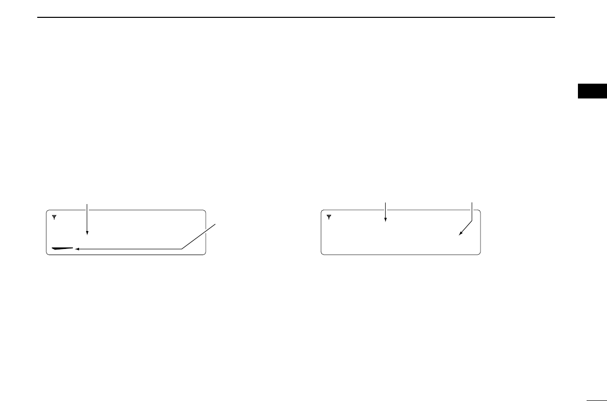
DTX Status message selection
(Digital mode operation only)
If the transceiver has [TX Status] assigned to it, the indication
can be toggled between the operating channel name (and the
channel number)* and the Status message (and the Status
channel.)* When the Status message (and the Status chan-
nel)* is displayed, [CH Up] or [CH Down] selects the desired
Status message.
qPush [TX Status]— Status message (and Status channel)*
appears.
wPush [CH Up] or [CH Down] to select the desired Status
message.
ePush [PTT] to transmit the selected Status message.
* Only when the 2 lines indication mode is selected.
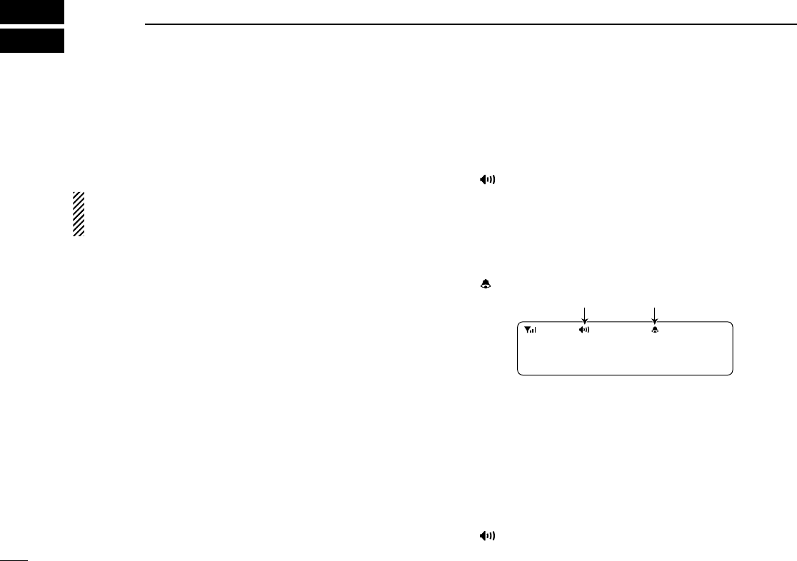
STATUS 01
TX Status 01
When the 2 lines indication mode is selected.
Status messageStatus channel
TGID01
When the 2 lines indication mode is selected
and [Talkgroup] is assigned to [P0].
Talkgroup ID name
Appears above the
key that [Talkgroup]
is assinged after
pushed.

13
2BASIC OPERATION
DDTMF transmission
If the transceiver has [DTMF Autodial] assigned to it, the auto-
matic DTMF transmission function is available. Up to 8 DTMF
channels are available.
qPush [DTMF Autodial]— a DTMF channel appears.
wPush [CH Up] or [CH Down] to select the desired DTMF
channel.
ePush [DTMF Autodial] to transmit the DTMF code in the
selected DTMF channel.
■Scrambler function
The voice scrambler function provides private communication
between stations. The frequency inversion type is equipped
to all versions, moreover, the optional Rolling or Non-rolling
type can be available.
qPush [Scrambler] to turn the scrambler function ON.
• “ ” appears.
wPush [Scrambler] again to turn the scrambler function
OFF.
• “ ” disappears.
14
2
BASIC OPERATION
2
■User set mode
User set mode is accessed with [User Set Mode] and allows
you to set seldom-changed settings. In this case you can
“customize” the transceiver operation to suit your preferences
and operating style.
Entering the user set mode:
qWhile pushing and holding [P1] and [P2], push [ ] to turn
the power ON. Then, push and hold [P0] to enter user set
mode.
wPush [P0] several times to select the appropriate item.
Then, push [Up] or [Down] to set the desired level/condi-
tion.
• Available set mode functions are Backlight, LCD Contrast,
Beep, Beep Level, Ringer Level, SQL Level, AF Min Level,
Mic Gain, Horn and Signal Moni.
ePush and hold [ ] to turn power OFF, then ON again to
exit set mode.
User set mode is also available via a programmable key.
Please refer to p. 6 [User Set Mode] section.
[ ]
[P0] [Up]/[Down]
[P1][P0] [P2] [ ]
15
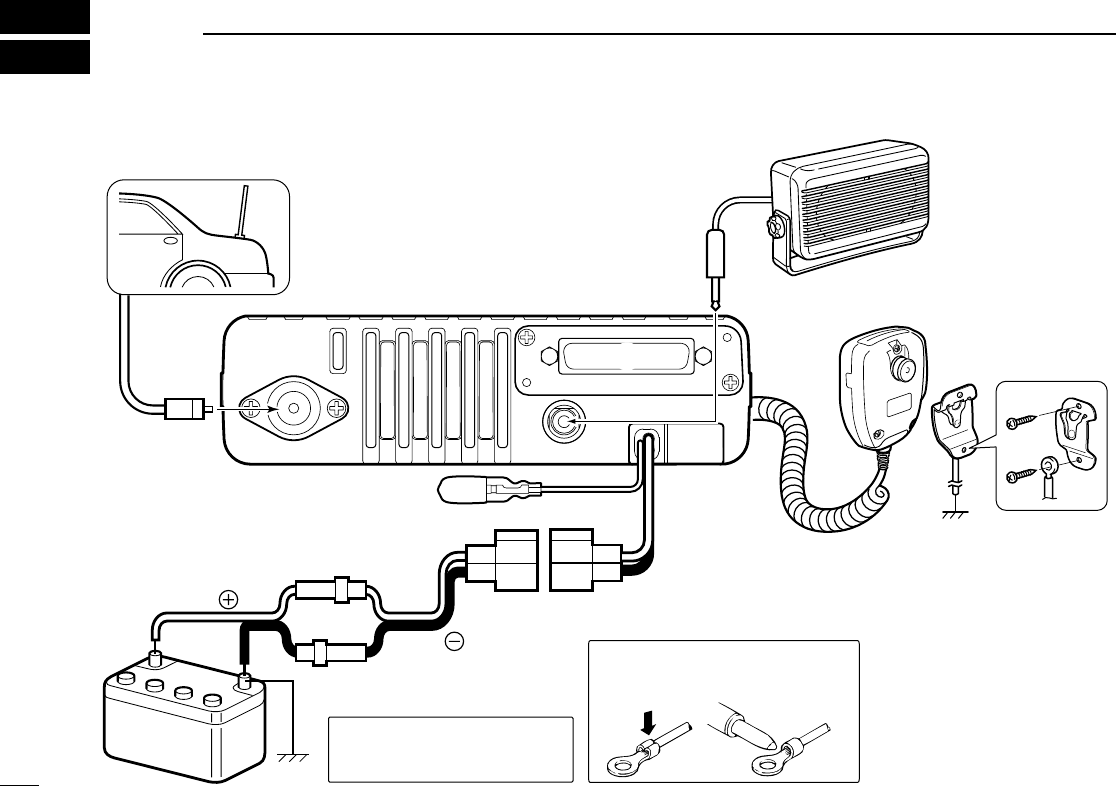
3CONNECTION AND MAINTENANCE
Antenna
Black
Red
12V
Battery
Solder
Crimp
NOTE: Use the terminals as shown
below for the cable connections.
R CAUTION! NEVER remove
the fuse-holder from the DC
power cable.
q ANTENNA CONNECTOR
Connects to an antenna.
Contact your dealer about
antenna selection and
placement.
q
e EXTERNAL
SPEAKER JACK
w D-Sub 25-pin
Connect a 4–8 Ω
external speaker.
Connect an exter-
nal unit.
r MICROPHONE HANGER
Connect the supplied mi-
crophone hanger to the
vehicle’s ground for mi-
crophone on/off hook
functions. (See p. ?)
t IGNITION LEAD
t
y DC POWER RECEPTACLE
Connects to a 12 V DC battery. Pay atten-
tion to polarities. NEVER connect to a 24 V
battery. This could damage the transceiver.
r
y
Optional speaker
w
e
Connects to a ignition line.
RDo not put a pressure
to this lead.
■Rear panel connection
16
3
CONNECTION AND MAINTENANCE
1
2
3
4
5
6
7
8
9
10
11
12
13
14
15
16
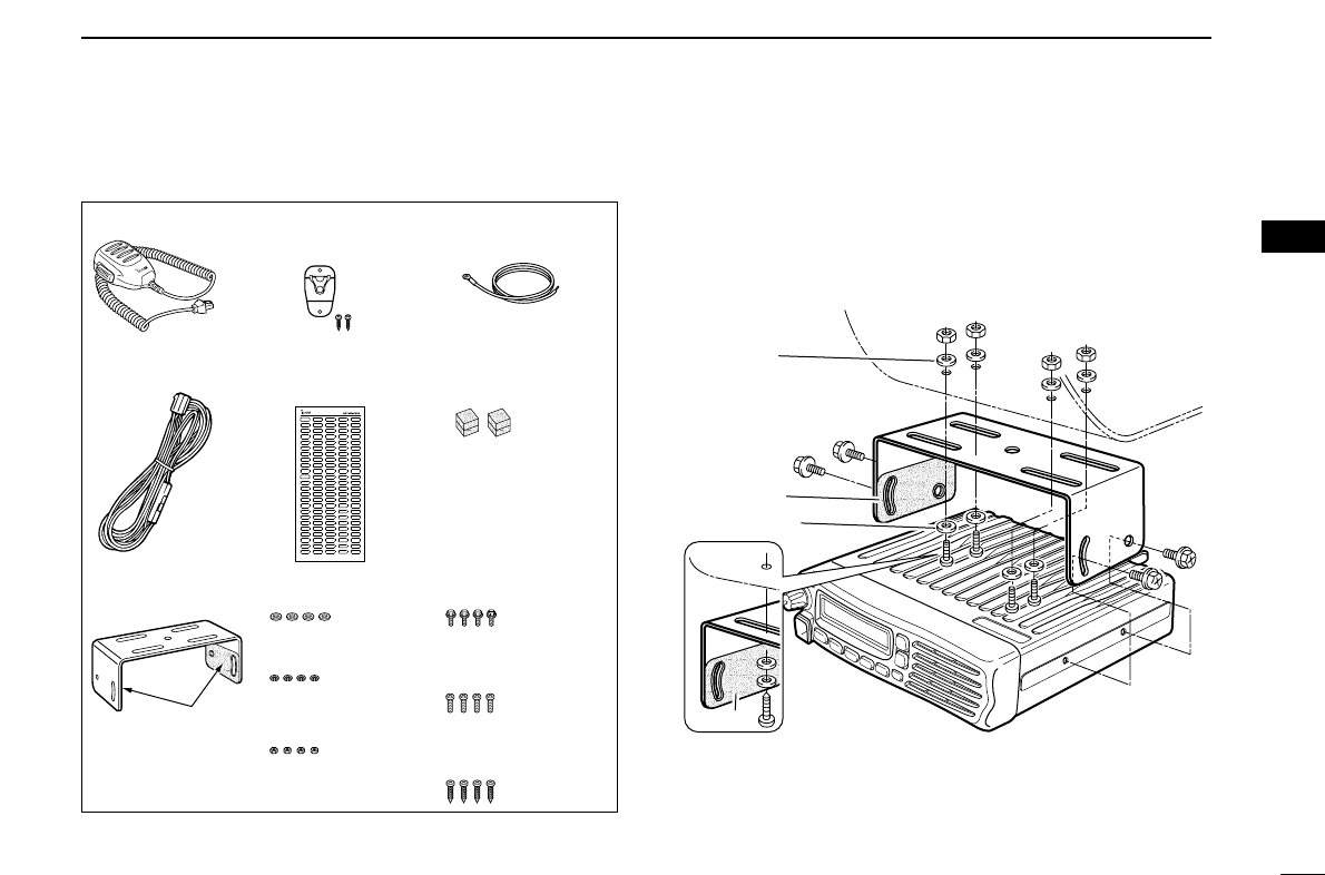
■Supplied Accessories ■Mounting the transceiver
The universal mounting bracket supplied with your transceiv-
er allows overhead mounting.
•Mount the transceiver securely with the 4 supplied screws
to a thick surface which can support more than 1.5 kg.
Flat washer
Felt*
Spring washer
When using
self-tapping screws
Felt*
*Felts reduce the vibration effects.
Microphone Microphone hanger
and screw set
Microphone
hanger cable
DC power cable Sponges
Mounting bracket
and felts
Flat washers
Spring washers
Bracket bolts
Mounting screws
(M5×12)
Self-tapping screws
(M5×16)
Nuts
Function name
stickers
Felts are already
attached.
17
3CONNECTION AND MAINTENANCE
■Antenna
A key element in the performance of any communication sys-
tem is an antenna. Contact your dealer about antennas and
the best places to mount them.
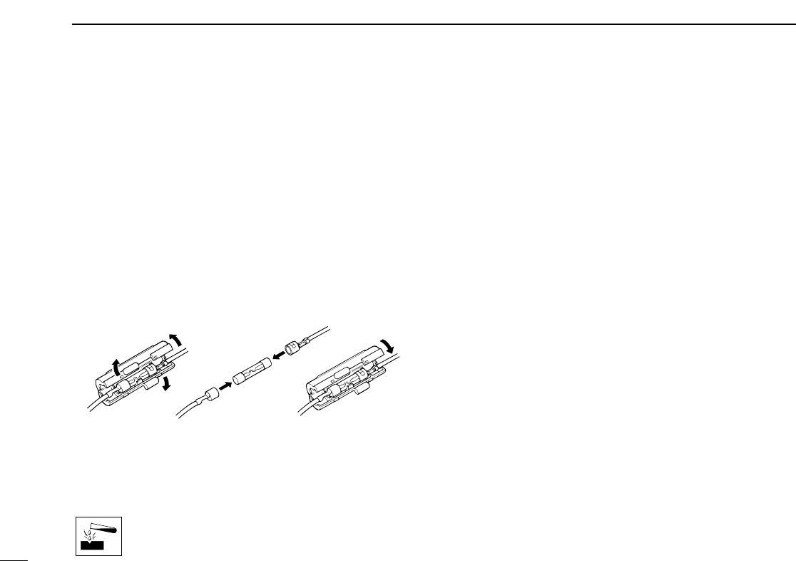
■Fuse replacement
A fuse is installed in the supplied DC power cable. If a fuse
blows or the transceiver stops functioning, track down the
source of the problem if possible, and replace the damaged
fuse with a new rated one.
❑Fuse rating: 20 A
USE the 20 A fuse only.
■Cleaning
If the transceiver becomes dusty or dirty, wipe it clean with a
soft, dry cloth.
AVOID the use of solvents such as benzene or
alcohol, as they may damage the transceiver sur-
faces.
■Options
• RMK-3
SEPARATION KIT
+
OPC-607/OPC-608/OPC-609
SEPARATION CABLE
Allows you to install the transceiver main unit separately
from the front panel for operating convenience.
• SP-5/SP-10/SP-22
EXTERNAL SPEAKER
Input impedance : 4 Ω
Max. input power : 5 W
SP-5 : Large speaker for good audio quality.
SP-10 : For all-round mobile operation.
SP-22 : Compact and easy-to-install. The same as supplied
with the transceiver (depending on version.)
• HM-152/HM-152T/HM-148
HAND MICROPHONE
HM-152 : Hand microphone
HM-152T : DTMF microphone
HM-148 : Heavy duty microphone
• SM-25
DESKTOP MICROPHONE
• UT-109R/UT-110R
SCRAMBLER UNITS
Non-rolling type (UT-109R)/Rolling type (UT-110R) voice
scrambler unit provides higher communication security.
• UT-96R 5
TONE UNIT
• UT-119
DIGITAL MODULATOR
/
DEMODULATOR UNIT
Provides 6.25/12.5 kHz narrow bandwidth digital mode
operation.
18
4
SAFETY TRAINING INFORMATION
1
2
3
4
5
6
7
8
9
10
11
12
13
14
15
16
Your Icom radio generates RF electromagnetic
energy during transmit mode. This radio is
designed for and classified as “Occupational Use
Only”, meaning it must be used only during the
course of employment by individuals aware of the
hazards, and the ways to minimize such hazards.
This radio is NOT intended for use by the “General
Population” in an uncontrolled environment.
• For compliance with FCC and Industry Canada RF Exposure
Requirements, the transmitter antenna installation shall comply with
the following two conditions:
1. The transmitter antenna gain shall not exceed 0 dBi.
2. IC-F5061/IC-F5063:
The antenna is required to be located outside of a vehicle and
kept at a distance of 1 meter or more between the transmitting
antenna of this device and any persons during operation. For
small vehicle as worst case, the antenna shall be located on the
roof top at any place on the centre line along the vehicle in order
to achieve 1 meter separation distance. In order to ensure this
distance is met, the installation of the antenna must be mounted
at least 1 meter away from the nearest edge of the vehicle in
order to protect against exposure to bystanders.
3. IC-F2721/IC-F2721D/IC-F2821/IC-F2821D:
The antenna is required to be located outside of a vehicle and
kept at a distance of ?? centimeters or more between the trans-
mitting antenna of this device and any persons during operation.
For small vehicle as worst case, the antenna shall be located on
the roof top at any place on the centre line along the vehicle in
order to achieve ?? centimeters separation distance. In order to
ensure this distance is met, the installation of the antenna must
be mounted at least ?? centimeters away from the nearest edge
of the vehicle in order to protect against exposure to bystanders.
To ensure that your exposure to RF electromag-
netic energy is within the FCC allowable limits
for occupational use, always adhere to the fol-
lowing guidelines:
•DO NOT operate the radio without a proper antenna attached, as
this may damage the radio and may also cause you to exceed FCC
RF exposure limits. A proper antenna is the antenna supplied with
this radio by the manufacturer or an antenna specifically authorized
by the manufacturer for use with this radio.
•DO NOT transmit for more than 50% of total radio use time (“50%
duty cycle”). Transmitting more than 50% of the time can cause FCC
RF exposure compliance requirements to be exceeded. The radio
is transmitting when the “TX indicator” lights red. You can cause the
radio to transmit by pressing the “PTT” switch.
Electromagnetic Interference/Compatibility
During transmissions, your Icom radio generates RF energy that can
possibly cause interference with other devices or systems. To avoid
such interference, turn off the radio in areas where signs are posted
to do so. DO NOT operate the transmitter in areas that are sensitive
to electromagnetic radiation such as hospitals, aircraft, and blasting
sites.
WARNING
CAUTION

MEMO

MEMO

1-1-32 Kamiminami, Hirano-ku, Osaka 547-0003, Japan
A-6565D-1EX
Printed in Japan
© 2006 Icom Inc.
Printed on recycled paper with soy ink.

OPERATING GUIDE
GUIDE TO OPERATING
LAND TRANSCEIVERS
WITH BIIS/MDC/LTR SYSTEMS

i
IMPORTANT
Thank you for purchasing this Icom radio. The BIIS/MDC/LTR
system functions are added to your IC-F5060 series radio.
READ ALL INSTRUCTIONS carefully and completely
before using the transceiver.
SAVE THIS OPERATING GUIDE —This operating
guide contains important operating instructions for;
• IC-F5061/F5062/F5063 VHF MOBILE TRANSCEIVERS
• IC-F6061/F6062/F6063 UHF MOBILE TRANSCEIVERS
NOTE: In this operating guide, the LCD illustration is
described using the 2 lines indication mode.
TABLE OF CONTENTS
IMPORTANT …………………………………………………… i
TABLE OF CONTENTS ……………………………………… i
1 PREPARATION …………………………………………… 1
■Programmable function keys …………………………… 1
2 BIIS 1200 OPERATION ……………………………… 2–11
■Default setting …………………………………………… 2
■Receiving a call ………………………………………… 2
■Transmitting a call ……………………………………… 4
■Receiving a message …………………………………… 6
■Transmitting a status …………………………………… 8
■Position data transmission …………………………… 10
■Printer connection ……………………………………… 10
■Digital ANI ……………………………………………… 10
■Auto emergency transmission ………………………… 10
■Stun function …………………………………………… 11
■BIIS indication ………………………………………… 11
■Priority A channel selection …………………………… 11
■Horn output …………………………………………… 11
3 MDC 1200 OPERATION …………………………… 12–19
■MDC 1200 system operation ………………………… 12
■Receiving a call ………………………………………… 12
■Transmitting a call ……………………………………… 15
4 LTR OPERATION …………………………………… 20–21
■Receiving a call ………………………………………… 20
■Transmitting a call ……………………………………… 21
Icom, Icom Inc. and the logo are registered trademarks of Icom
Incorporated (Japan) in the United States, the United Kingdom, Germany,
France, Spain, Russia and/or other countries.
All other products or brands are registered trademarks or trademarks of their
respective holders.

1
1
PREPARATION
1
2
3
4
5
6
7
8
9
10
11
12
13
14
15
16
■Programmable function keys
The following functions for MDC 1200 system operation can
be assigned to the programmable function keys;
[UP], [DOWN], [P0], [P1], [P2], [P3] and [P4]
Consult your Icom dealer or system operator for details con-
cerning your transceivers programming.
If the programmable function names are bracketed in the fol-
lowing explanations, the specific key is used to activate the
function depends on the programming.
DFor BIIS mode operation only
DIGITAL BUTTON KEY
➥Push to select the call ID list, transmit message and stand-
by condition. Toggles between queue channel and received
message record indication after queue channel is selected.
➥Push and hold to select queue channel indication.
STATUS UP/DOWN KEYS
➥While in the standby condition, push to display the trans-
mit status indication and select a status number.
➥When a received SDM is displayed, push to cancel the
automatic scroll and scroll the message manually.
➥When an SDM that contains more than 12 characters is
displayed, push to scroll the message manually.
10 KEY ENTER KEY
Push to enable the connected microphone’s 10-keypad oper-
ation.
DFor MDC mode operation only
MDC CALL KEY
➥Push to enter the MDC menu selection mode. Then select
the desired MDC menu from “SELCALL,” “CALALERT,”
“STUN,” “REVIVE,” “RADIOCHK,” “STATUS” and “MSG”
using [CH Up], [CH Down], [MDC Up] or [MDC Down].
After selection, push this key again to enter the transceiver
alias or message channel selection mode.
➥While in the transceiver alias or message channel selection
mode, push to return to the MDC menu selection mode.
MDC UP AND DOWN KEYS
➥Push to select the MDC menu after entering the MD menu
selection mode.
➥Push to select the desired transceiver alias or message
channel while in the transceiver alias or message channel
selection mode.
MDC SELCALL KEY
Push to enter the transceiver alias selection mode.
• After the desired alias selection, push [PTT] to transmit a SelCall.
MDC CALLALERT KEY
Push to enter the transceiver alias selection mode.
• After the desired alias selection, push [PTT] to transmit a CallAlert.
DFor LTR mode operation only
PHONE KEY
Push to connect or disconnect the telephone network con-
nection.
2
2BIIS 1200 OPERATION
■Default setting
The following functions are assigned to each programmable
key as the default. However, the assigned function can be
changed by your dealer. Ask your dealer for details.
NOTE:
• During digital mode operation, BIIS 1200 is not available.
• [TX Code Enter] must be assigned to a key.
[P0]; Call : Push to transmit a 5-tone/BIIS call
when the selected channel is a 5-
tone or MSK channel.
[P1]; Digital : Push to select the call list ID/transmit
message, or to display the receive
message record for selection.
[P3]; TX Code Enter : Push to enter the ID code edit mode
directly for both 5-tone and MSK.
[P4]; Moni(Audi) : Push this key after the communica-
tion to send a ‘Clear down’ signal
during MSK channel operation.
[P2]; Null : No function is assigned.
[Up]/[Down]; CH Up/Down
: While in the standby condition, push
to select the operating channel.
After pushing [Digital] or [TX Code
CH Select], push to select call list or
TX code channel, respectively.
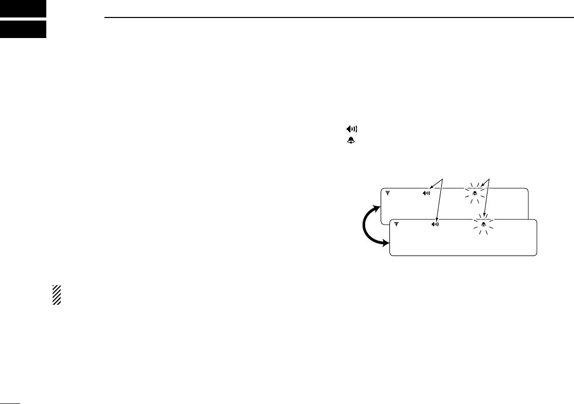
■Receiving a call
DDIndividual call
qWhen an individual call is received;
• Beeps sound.
• “ ” appears and the mute is released.
• The programmed text message (e.g.“CALLING”) and the calling
station ID (or text) is displayed when the indication mode is 2
lines.
• The programmed text message (e.g.“CALLING”) and the calling
station ID (or text) is displayed alternately when the indication
mode is 1 line, depending on the setting.
• “ ” appears or blinks depending on the setting.
wPush and hold [PTT], then speak into the microphone at a
normal voice level.
• TX indicator lights red.
eRelease [PTT] to return to receive.
• BUSY indicator lights green while receiving a signal.
rTo finish the conversation, push [P4] (Moni(Audi)) to send
the ‘Clear down’ signal.
• Either station can send a ‘Clear down’ signal.
•“CLR DOWN” is displayed for 2 sec. (approx.).
• “ ” disappears and the transceiver returns to the standby con-
dition.
Appears or blinksAppears
CALLING
0500
3
2
BIIS 1200 OPERATION
1
2
3
4
5
6
7
8
9
10
11
12
13
14
15
16
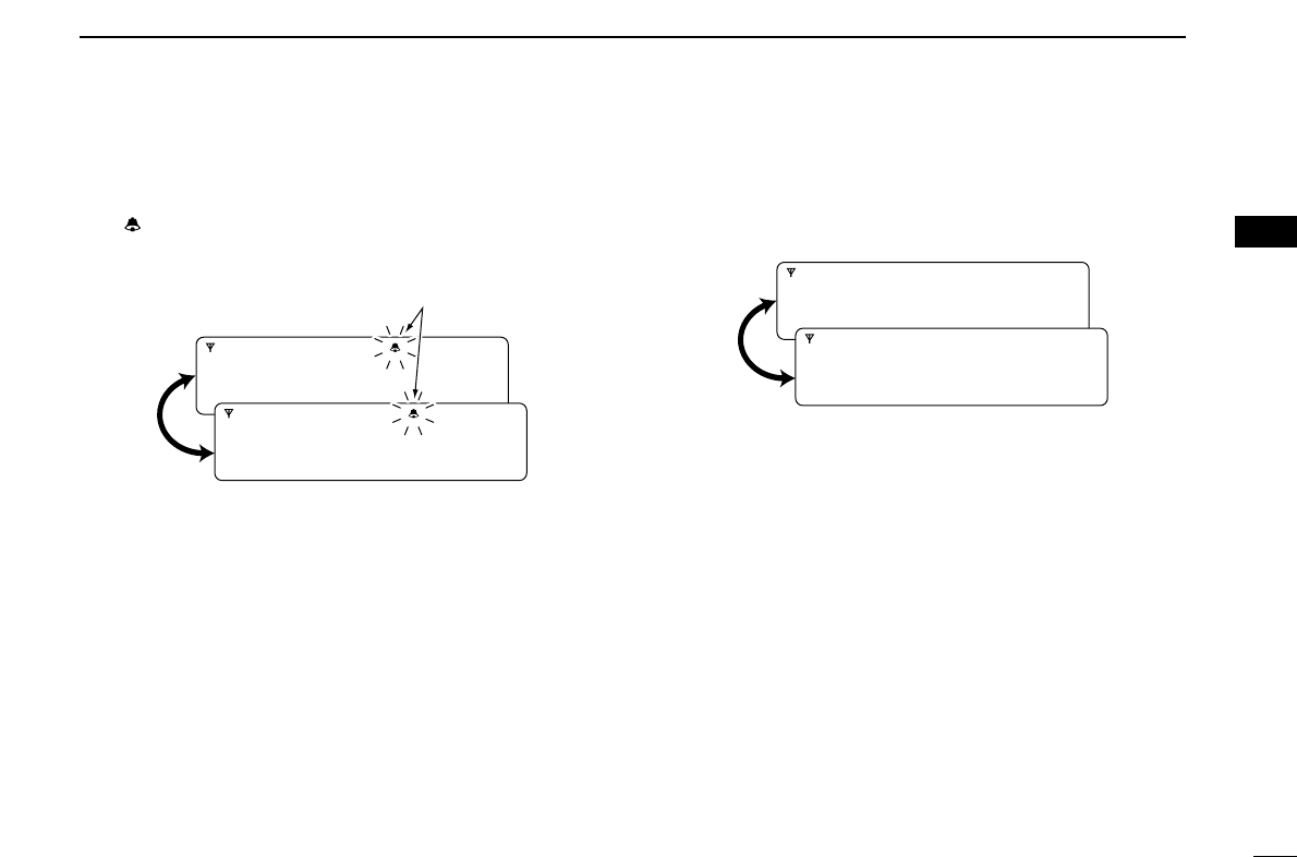
DDGroup call
qWhen a group call is received;
•Beeps sound.
•“ ” appears and the mute is released.
•The programmed text message (e.g.“GROUP”) and the calling sta-
tion ID (or text) is displayed when the indication mode is 2 lines.
•The programmed text message (e.g.“GROUP”) and the calling
station ID (or text) is displayed alternately when the indication
mode is 1 line, depending on the setting.
•“ ” appears or blinks depending on the setting.
wPush and hold [PTT], then speak into the microphone at a
normal voice level.
•TX indicator lights red.
NOTE: Only one station is permitted to speak.
eRelease [PTT] to return to receive.
•BUSY indicator lights green while receiving a signal.
rTo finish the conversation, push [MONITOR] (Moni(Audi))
to send the ‘Clear down’signal.
•Either station can send a ‘Clear down’signal.
•“CLR DOWN” is displayed for 2 sec. (approx.)
•“ ” disappears and the transceiver returns to the standby con-
dition.
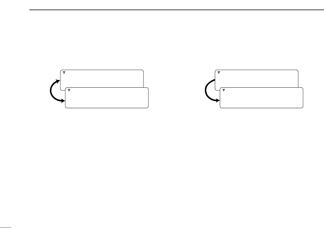
DDDisplaying the received call record
— Queue indication
The transceiver memorizes the calling station ID in the mem-
ory. Up to 3 calls can be memorized, and the oldest call
record is erased when a 4th call is received. However, once
the transceiver is powered OFF, the all records are cleared.
qPush [P1] (Digital) for 1 sec.
•Displays following indication.
When a record is available
When no record is available
wPush [Up] or [Down], or rotate [DIAL] to select the desired
call.
ePush [P1] (Digital) for 1 sec. again to return to the standby
condition.
•When no operation is performed for 30 sec., the transceiver
returns to the standby condition automatically.
<QUEUE>
NO QUEUE
<QUEUE>
-QUEUE!-
Appears or blinksAppears
GROUP
1120
4
2BIIS 1200 OPERATION
■Transmitting a call
A total of 3 ways for code selection are available—selecting
the call code from memory, entering the call code from the
keypad and calling back from the queue channel record.
DDUsing call memory
qWhile in the standby condition, push [P1] (Digital) to enter
the call code memory channel selection mode.
•“ ” appears.
wPush [Up] or [Down], or rotate [DIAL] to select the desired
call code.
ePush [P0] (Call) or [PTT]* to call.
*PTT call can be made only when PTT call capability is permitted.
NOTE: When no answer back is received, the trans-
ceiver repeats the call 3 times (default) automatically,
and “WAIT”is displayed during each call. However, an
error beep sounds and “FAILED”is displayed when no
answer back is received after the calls.
rPush [PTT] to transmit; release to receive.
tPush [P4] (Moni(Audi)) to send the ‘Clear down’signal.
DDCalling back from the queue channel
qWhile in the standby condition, push [P1] (Digital) for
1 sec. to enter the queue memory channel selection mode.
wPush [Up] or [Down] or rotate [DIAL] to select the desired
record.
ePush [P0] (Call) or [PTT]* to call.
*PTT call can be made only when PTT call capability is permitted.
NOTE: When no answer back is received, the trans-
ceiver repeats the call 3 times (default) automatically,
and “WAIT”is displayed during each call. However, an
error beep sounds and “FAILED”is displayed when no
answer back is received after the calls.
rPush [PTT] to transmit; release to receive.
tPush [P4] (Moni(Audi)) to send the ‘Clear down’signal.
<QUEUE>
-QUEUE!-
CALLING
0500
Appears

5
2
BIIS 1200 OPERATION
1
2
3
4
5
6
7
8
9
10
11
12
13
14
15
16
DDDirect code entry
qWhile in the standby condition, push [P3] (TX Code Enter)
to enter the TX code edit mode.
•Code digit for editing blinks.
wPush [P3] (TX Code Enter) to select the desired digit to be
edited.
•Digit for editing differs according to the setting.
eSet the desired digit using [CH Up]/[CH Down].
rPush [P3] (TX Code Enter) to set the digit, then the digit
to the right will blink automatically.
tRepeat eand rto input all allowable digits.
yPush [P0] (Call) or [PTT]* to call.
*PTT call can be made only when PTT call capability is permitted.
NOTE: When no answer back is received, the trans-
ceiver repeats the call 3 times (default) automatically,
and “WAIT”is displayed during each call. However, an
error beep sounds and “FAILED”is displayed when no
answer back is received after the calls.
uPush [PTT] to transmit; release to receive.
iPush [P4] (Moni(Audi)) to send the ‘Clear down’signal.
For your information
When the “UpDate” setting for the call code is enabled, the
set code is overwritten into the call code memory.
0500
6
2BIIS 1200 OPERATION
■Receiving a message
DDReceiving a status message
qWhen a status message is received;
• Beeps sound.
• The calling station ID (or text) and the status message is dis-
played alternately when the indication mode is 1 line, depending
on the setting.
wPush [P4] (Moni(Audi)) to return to the standby condition.
NOTE: Only the calling station ID (or text) is displayed (no
message is displayed alternately) when the scroll timer is
set to ‘OFF.’In this case, push [Status Up]/[Status Down]
to display the status message manually.
DDReceiving an SDM (Short Data Message)
qWhen an SDM is received;
• Beeps sound.
• The calling station ID (or text) and the SDM is displayed alter-
nately when the indication mode is 1 line, depending on the set-
ting.
• “” appears
wWhen the received SDM includes more than 12 charac-
ters, the message scrolls automatically, when the auto-
matic scroll function is activated.
• Push [Status Up]/[Status Down] to scroll the message manually.
ePush [P4] (Moni(Audi)) to return to the standby condition.
SDM12345678
BASE
SDM 8
BASE
Appears
RX Status 01
BASE
7
2
BIIS 1200 OPERATION
1
2
3
4
5
6
7
8
9
10
11
12
13
14
15
16
DDReceived message selection
The transceiver memorizes the received message in the
memory. Up to 6 messages for status and SDM, or 95 char-
acter SDM’s can be memorized. The oldest message is
erased when the 7th message is received. However, once the
transceiver is powered OFF, all messages are cleared.
qPush [P1] (Digital) for 1 sec.
•Displays queue memory.
wPush [P1] (Digital) momentarily.
•Displays message memory.
When a message is available
When no message is available
ePush [Up] or [Down], or rotate [DIAL] to select the desired
message.
•When selecting the SDM that includes more than 12 characters,
the message scrolls automatically when the automatic scroll
function is activated.
• Push [Status Up]/[Status Down] to scroll the message manually.
rPush [P1] (Digital) for 1 sec. again to return to the standby
condition.
•When no operation is performed for 30 sec., the transceiver
returns to the standby condition automatically.
MESSAGE
-NO MSG-
MESSAGE
-MSG!-

8
2BIIS 1200 OPERATION
■Transmitting a status
DDGeneral
The status message can be selected with the programmed
text, and the message text is also displayed on the function
display of the called station.
Up to 24 status types (1 to 24) are available, and the status
messages 22 and 24 have designated meanings.
Status 22: Emergency*
Status 24: GPS request
*The status 22 can also be used as a normal status message by
disabling the designated meaning. However, the status 24 is fixed.
The status call can be sent with both individual and group
calls.
DDTransmitting a status
qWhile in the standby condition, push [P1] (Digital), then
push [Up] or [Down], or rotate [DIAL] to select the desired
station/group code.
wPush [P1] (Digital) again, then push [UP] or [DOWN] to
select the desired status message.
Or, you can select the desired status message using
[Status Up]/[Status Down] key directly.
ePush [P0] (Call) or [PTT]* to transmit the status message
to the selected station/group.
*PTT call can be made only when PTT call capability is permitted.
•2 beeps will sound and the transceiver returns to the standby
condition automatically when the transmission is successful.
STATUS 01
TX Status 01
Status message is displayed.

9
2
BIIS 1200 OPERATION
1
2
3
4
5
6
7
8
9
10
11
12
13
14
15
16
DDGeneral
The short data message, SDM, can be sent to an individual
station or group stations. Also, 8 SDM memory channels are
available and the messages can be edited via PC program-
ming.
DDTransmitting an SDM
qWhile in the standby condition, push [P1] (Digital), then
push [Up] or [Down] or rotate [DIAL] to select the desired
station/group code.
wPush [P1] (Digital) again, then push [Up] or [Down] or
rotate [DIAL] to select the desired SDM.
Or, you can select the desired SDM using [Status Up]/
[Status Down] key directly.
ePush [P0] (Call) or [PTT]* to transmit the SDM to the
selected station/group.
*PTT call can be made only when PTT call capability is permitted.
•2 beeps will sound and the transceiver returns to the standby
condition automatically when the transmission is successful.
MESSAGE 1
SDM 1
SDM is displayed.
Appears

10
2BIIS 1200 OPERATION
■Position data transmission
When the optional cable and a GPS receiver is connected to
the transceiver, the position (longitude and latitude) data can
be transmitted automatically.
Ask your dealer or system operator for connection details.
The position data is transmitted when;
•Status 24 message is received
*When the status 24 message, GPS request, is received.
•Fully automatic
When automatic position transmission is enabled, send
the position data according to ‘Time Marker’and ‘Interval
Timer’settings.
•PTT is released
When ‘Send with Logoff’is enabled.
-Set the ‘Log-In/Off’item as ‘L-OFF.’
•After sending a status message
When ‘Send with Status’is enabled.
•After sending an SDM
When ‘Send with SDM’is enabled.
•After sending status 22 (Emergency)
When ‘Send with Emergency’is enabled.
■Printer connection
When the printer is connected to the D-sub 25-pin of the trans-
ceiver, the received SDM content and the ID of the station who
sent the message can be printed out. Ask your dealer or sys-
tem operator for connection details.
■Digital ANI
The own ID can be transmitted each time the PTT is pushed
(log-in) or released (log-off) during individual or group call
communications.
By receiving the ANI, the communication log can be recorded
when using a PC dispatch application.
In addition, when using the ANI with log-in, the PTT side tone
function can be used to inform you that the ID is sent and
voice communication can be performed.
■Auto emergency transmission
When [Emergency Single (Silent)] or [Emergency Repeat
(Silent)] is pushed, an emergency signal is automatically
transmitted for the specified time period.
The status 22 (Emergency) is sent to the selected ID station,
and the position data is transmitted after the emergency sig-
nal when a GPS receiver is connected to the transceiver.
The emergency transmission is performed on the emergency
channel, however, when no emergency channel is specified,
the signal is transmitted on the previously selected channel.
There is no change in the function display or beep emission
during automatic emergency transmission.

11
2
BIIS 1200 OPERATION
1
2
3
4
5
6
7
8
9
10
11
12
13
14
15
16
■Stun function
When the specified ID, set as a killer ID, is received, the stun
function is activated.
When the killer ID is received, the transceiver switches to the
password required condition. Entering of the password via the
keypad is necessary to operate the transceiver again in this
case.
■BIIS indication
The following indications are available for the BIIS operation
on an MSK channel.
CONNECT : Individual/group call is successful.
OK : Message (status or SDM) transmission is suc-
cessful.
FAILED : No answer back is received.
WAIT : Appears during retry of the call (2nd call).
CLR DOWN : End the communication.
BUSY : Operating channel is in the busy condition.
■Priority A channel selection
When one of the following operations is performed, the trans-
ceiver selects the Priority A channel automatically.
Priority A is selected when;
•Clear down signal is received/transmitted
- Set the ‘Move to PrioA CH’item as ‘Clear down.’
•Turning the power ON
The Priority A channel is selected each time the transceiv-
er power is turned ON.
•Status call
The Priority A channel is selected when transmitting a sta-
tus call.
- Enable the ‘Send Status on PrioA CH’item in the MSK
configuration.
■Horn output
Automatic honking function is available when the horn honk
equipment is connected to D-Sub 25-pin of the transceiver.
When a status message is received, the transceiver controls
the vehicles horn for the specified time period to inform a sta-
tus message is received.
This function is convenient when the operator away from the
transceiver.
Ask your dealer or system operator, or refer to the service
manual for connection and setting details.
12
3MDC 1200 OPERATION
■MDC 1200 system operation
The MDC 1200 signaling system enhances your transceiver’s
capabilities. It allows PTT ID, Selective Calling, CallAlert,
Radio Check, Stun, Revive, Status, Messaging and
Emergency signaling. Also, the dispatcher can stun and
revive transceivers on the system.
An additional feature of MDC 1200 found in Icom transceivers
is called aliasing. Each transceiver on the system has a
unique ID number. Aliasing allows the substitution of an
alphanumeric name for this ID number. For transmit, you can
use this alias to select a transceiver to call. For receive, the
alias of the calling station is displayed instead of the ID.
Please note that your dealer has set one of the programma-
ble keys ([UP], [DOWN], [P0], [P1], [P2], [P3] and [P4]) for
MDC 1200 operation.
NOTE: During digital mode operation, MDC 1200 is not
available.
■Receiving a call
DDReceiving a Selective Call
qWhen a selective call is received;
• Beeps sound.
• “” appears.
• “” blinks.
• The calling station ID (or alias) and “SELCALL” are displayed
alternately.
wPush and hold [PTT] and speak into the microphone.
eRelease [PTT] to receive a response.
SELCALL
ID 1234
BlinksAppears
13
3
MDC 1200 OPERATION
1
2
3
4
5
6
7
8
9
10
11
12
13
14
15
16
DDReceiving a CallAlert
qWhen a CallAlert is received;
• Beeps sound.
• “” blinks.
• The calling station ID (or alias) and “CALLALRT” are displayed
alternately.
wPush and hold [PTT] and speak into the microphone.
eRelease [PTT] to receive a response.
DDReceiving a Emergency Call
qWhen an emergency call is received;
• Beeps sound.
• The calling station ID (or alias) and “EMG EMG” are displayed
alternately until turning power OFF, the channel changing, etc.
wWhen the automatic acknowledgement function is turned
ON, the transceiver automatically transmits an acknowl-
edgement call to the station.
• The calling station stops calling.
eTurn power OFF, change the channel, etc. to stop the beep
and display indication.
ID 1234
EMG EMG
CALLALRT
ID 1234
Blinks
14
3MDC 1200 OPERATION
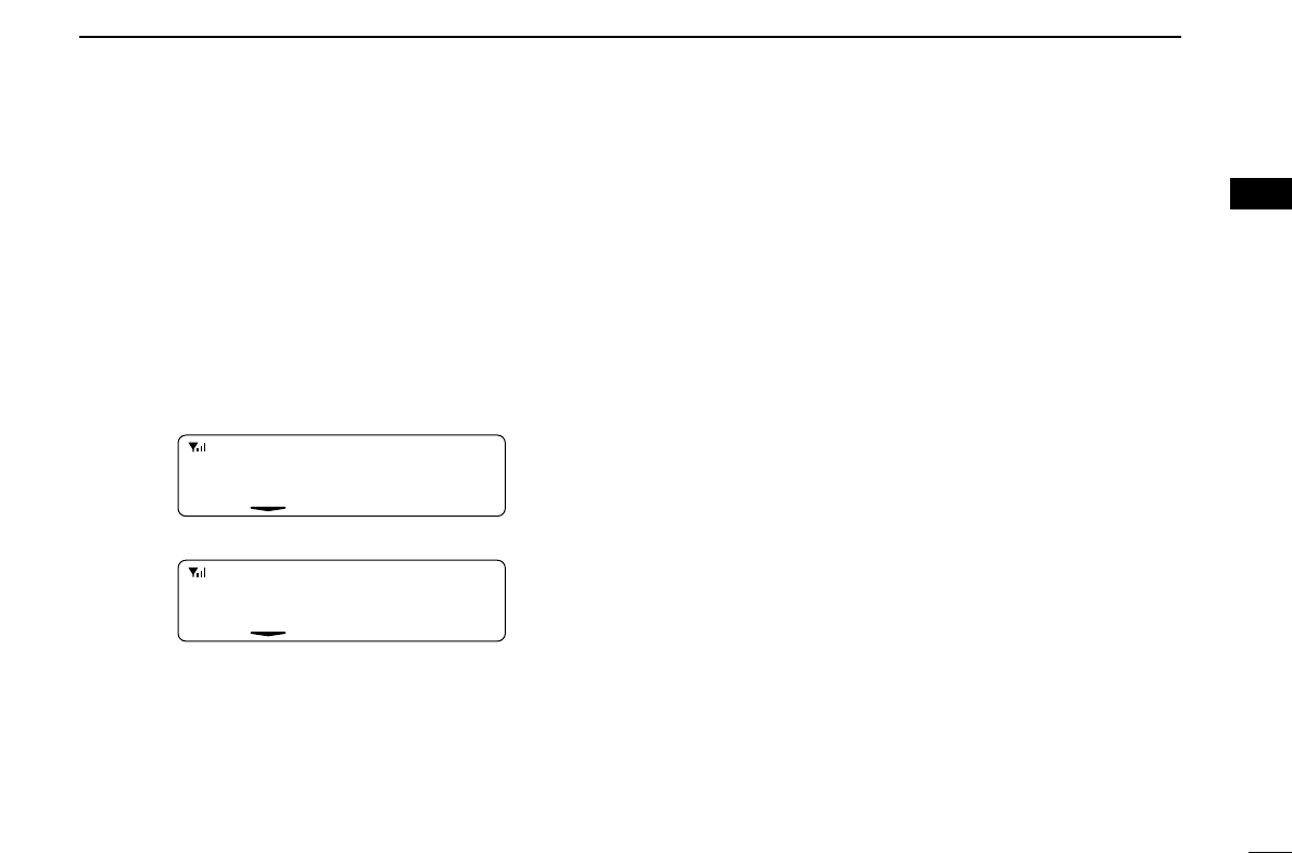
DDReceiving a Message
qWhen a Message is received;
• Beeps sound.
• The calling station ID (or alias) and the message are displayed
alternately.
wTurn power OFF, push [PTT], change the channel, etc. to
stop the display indication.
DDReceiving a Status Message
➥When a Status Message is received;
• Beeps sound.
• The calling station ID (or alias) and the status message are dis-
played once.
DDReceiving a Stun or Revive
If a Stun command is received that matches your station ID,
the transceiver will display “SORRY” and you can not receive
or transmit. When a Revive command is received that match-
es your station ID, normal operation is restored.
ID 1234
STATUS1
ID 1234
MSG 1

15
3
MDC 1200 OPERATION
1
2
3
4
5
6
7
8
9
10
11
12
13
14
15
16
■Transmitting a call
DDTransmitting a Selective Call
Selective calling allows you to make a call to a specific station
or to a particular group. Other MDC 1200 transceivers on the
channel will not receive a selective call that does not match
their station or group ID’s.
qPush [MDC Call] to enter the MDC menu selection mode.
• Or push [MDC SelCall] to enter the transceiver alias selection
mode. In this case, skip step w.
wPush [MDC Call] again to enter the transceiver alias selec-
tion mode.
eSelect the desired alias using [CH Up], [CH Down], [MDC
Up] or [MDC Down].
rPush and hold [PTT] to transmit the selective call to the
selected station, then speak into the microphone.
• “” appears.
tRelease [PTT] to receive.
DDTransmitting a CallAlert
CallAlert allows you to notify another user who may be away
from the transceiver that you want to talk.
qPush [MDC Call] to enter the MDC menu selection mode.
• Or push [MDC CallAlert] to enter the transceiver alias selection
mode. In this case, skip steps wand e.
wSelect “CALALERT” using [CH Up], [CH Down], [MDC
Up] or [MDC Down].
ePush [MDC Call] again to enter the transceiver alias selec-
tion mode.
rSelect the desired alias using [CH Up], [CH Down], [MDC
Up] or [MDC Down].
tPush [PTT] to transmit the CallAlert to the selected station.
• “CA CALL” is displayed.
yRelease [PTT].
• “CA OK” is displayed if the targeted station received the alert.
• “CA FAIL” is displayed if the targeted station does not send an
acknowledgement.
uAfter a specified time period has passed, the transceiver
will return to receive.
CALALERT
SELCALL

16
3MDC 1200 OPERATION
DDTransmitting a Stun Call
Stun call allows you to send MDC 1200 signal that will stun
the targeted station.
qPush [MDC Call] to enter the MDC menu selection mode.
wSelect “STUN” using [CH Up], [CH Down], [MDC Up] or
[MDC Down].
ePush [MDC Call] again to enter the transceiver alias selec-
tion mode.
rSelect the desired alias using [CH Up], [CH Down], [MDC
Up] or [MDC Down].
tPush [PTT] to transmit the stun call to the selected station.
• “STN TX” is displayed.
yRelease [PTT].
• “STN ACK” is displayed if the targeted station is turned ON, on
channel and within range.
• “STN FAIL” is displayed if the targeted station does not send an
acknowledgement.
uAfter a specified time period has passed, the transceiver
will return to receive.
DDTransmitting a Revive Call
Revive call allows you to send MDC 1200 signals that will
revive the targeted (stunned) station.
qPush [MDC Call] to enter the MDC menu selection mode.
wSelect “REVIVE” using [CH Up], [CH Down], [MDC Up]
or [MDC Down].
ePush [MDC Call] again to enter the transceiver alias selec-
tion mode.
rSelect the desired alias using [CH Up], [CH Down], [MDC
Up] or [MDC Down].
tPush [PTT] to transmit the revive call to the selected sta-
tion.
• “REV TX” is displayed.
yRelease [PTT].
• “REV ACK” is displayed if the targeted station is turned ON, on
channel and within range.
• “REV FAIL” is displayed if the targeted station does not send an
acknowledgement.
uAfter a specified time period has passed, the transceiver
will return to receive.
REVIVE
STUN

17
3
MDC 1200 OPERATION
1
2
3
4
5
6
7
8
9
10
11
12
13
14
15
16
DDTransmitting a Radio Check Call
Radio check call allows you to determine whether another
transceiver is turned on, within range and on channel without
requiring any action from the targeted station user.
qPush [MDC Call] to enter the MDC menu selection mode.
wSelect “RADIOCHK” using [CH Up], [CH Down], [MDC
Up] or [MDC Down].
ePush [MDC Call] again to enter the transceiver alias selec-
tion mode.
rSelect the desired alias using [CH Up], [CH Down], [MDC
Up] or [MDC Down].
tPush [PTT] to transmit the radio check call to the selected
station.
• “RDO CHK” is displayed.
yRelease [PTT].
• “CHK ACK” is displayed if the targeted station is turned ON, on
channel and within range.
• “CHK FAIL” is displayed if the targeted station does not send an
acknowledgement.
uAfter a specified time period has passed, the transceiver
will return to receive.
DDTransmitting a Status Message
Status Messaging allows you to send a pre-programmed sta-
tus message. There are 16 status codes that can be sent. In
addition, the dispatcher can send an MDC 1200 signal that
causes the transceiver to automatically transmit its current
status.
qPush [MDC Call] to enter the MDC menu selection mode.
wSelect “STATUS” using [CH Up], [CH Down], [MDC Up]
or [MDC Down].
ePush [MDC Call] again to enter the status message selec-
tion mode.
rSelect the desired status message using [CH Up], [CH
Down], [MDC Up] or [MDC Down].
tPush [PTT] to transmit the selected status message.
• “STAT TX” is displayed.
yRelease [PTT].
• “STAT OK” is displayed.
• “STA FAIL” is displayed if there is no acknowledgment from the
dispatcher.
uAfter a specified time period has passed, the transceiver
will return to receive.
STATUS
STATUS1
Pre-programmed
status message
is displayed.
STATUS
RADIOCHK
18
3MDC 1200 OPERATION
DDTransmitting a Message
The transceiver can send a pre-programmed message. There
are 16 messages that can be sent on a channel.
qPush [MDC Call] to enter the MDC menu selection mode.
wSelect “MSG” using [CH Up], [CH Down], [MDC Up] or
[MDC Down].
ePush [MDC Call] again to enter the pre-programmed mes-
sage selection mode.
rSelect the desired message using [CH Up], [CH Down],
[MDC Up] or [MDC Down].
tPush [PTT] to transmit the selected message.
• “MSG TX” is displayed.
yRelease [PTT].
• “MSG OK” is displayed.
• “MSG FAIL” is displayed if there is no acknowledgment from the
dispatcher.
uAfter a specified time period has passed, the transceiver
will return to receive.
MSG
MSG 1
Pre-programmed message is displayed.
MSG

19
3
MDC 1200 OPERATION
1
2
3
4
5
6
7
8
9
10
11
12
13
14
15
16
DDPTTID Calls
The transceiver can send an MDC 1200 signal that includes
PTTID when [PTT] is pushed (beginning of transmission) and
released (end of transmission). If a PTTID call is received, the
transceiver will display the calling station ID (or alias) and
emit a beep*.
*Depends on the setting.
DDEmergency Calls
The MDC 1200 Emergency feature can be accessed using
the [Emergency Single] or [Emergency Repeat] key
(described in the instruction manual). The transceiver will
repeatedly send an Emergency MDC 1200 command for a
programmed length of time until it receives an acknowledge-
ment signal.
The emergency call can be transmitted without a beep emis-
sion and LCD indication change depends on the setting.
With MDC 1200 Emergency, the transceiver can also be pro-
grammed to keep the microphone open during an emergency
call, allowing monitoring of the situation.
Ask your dealer for details.
20
4LTR OPERATION
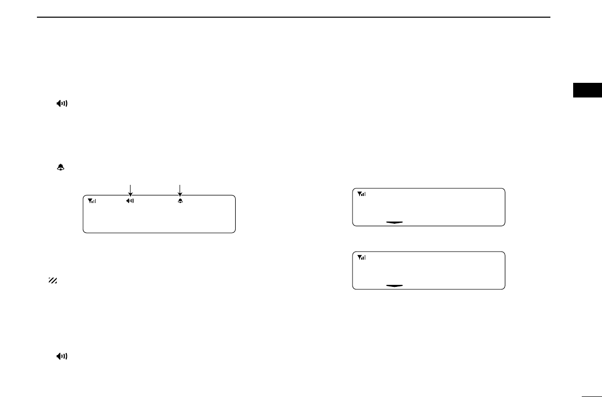
■Receiving a call
DGroup call
qPush [CH Up] or [CH Down] to select the LTR system
channel or talk group.
wWhen a call is received;
•‘BUSY’indicator lights green.
ePush and hold [PTT], then speak into the microphone at a
normal voice level.
rRelease [PTT] to return to receive.
DSelective call (DTMF call)
qPush [CH Up] or [CH Down] to select the LTR system
channel or talk group.
wPush [Call] to mute the channel.
eWhen receiving a call, the calling station name appears
and a beep is emitted. Then the mute is released.
•“ ” appears.
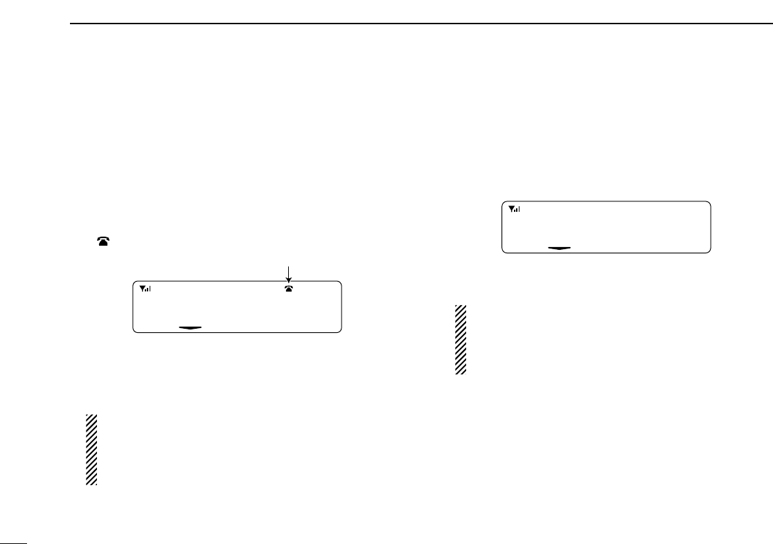
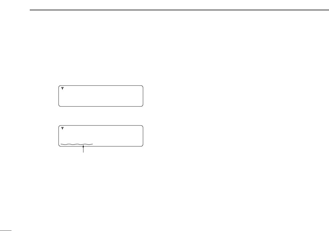
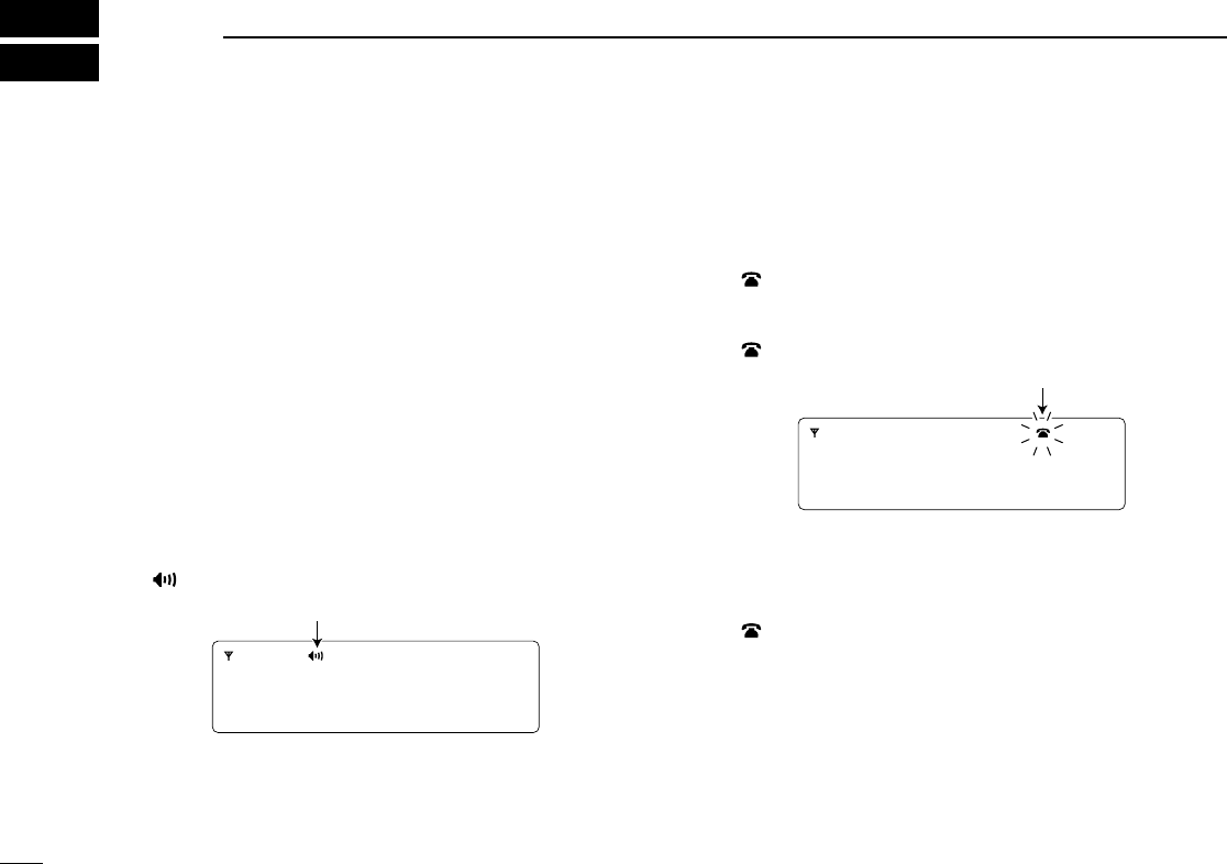
DPhone call
qPush [CH Up] or [CH Down] to select the phone channel of
LTR system channel.
•“ ” appears.
wWhen a phone call is received (transceiver rings), push
[Phone] (or push [PTT]).
•“ ” blinks.
ePush and hold [PTT], then speak into the microphone at a
normal voice level. Release [PTT] to return to receive.
rAfter conversation is finished, push [Phone] to disconnect
the phone call.
•“ ” stops blinking.
002 ch-03
fH 173.7M
Blinks
002 ch-03
fH 173.7M
Appears
21
4
LTR OPERATION
1
2
3
4
5
6
7
8
9
10
11
12
13
14
15
16
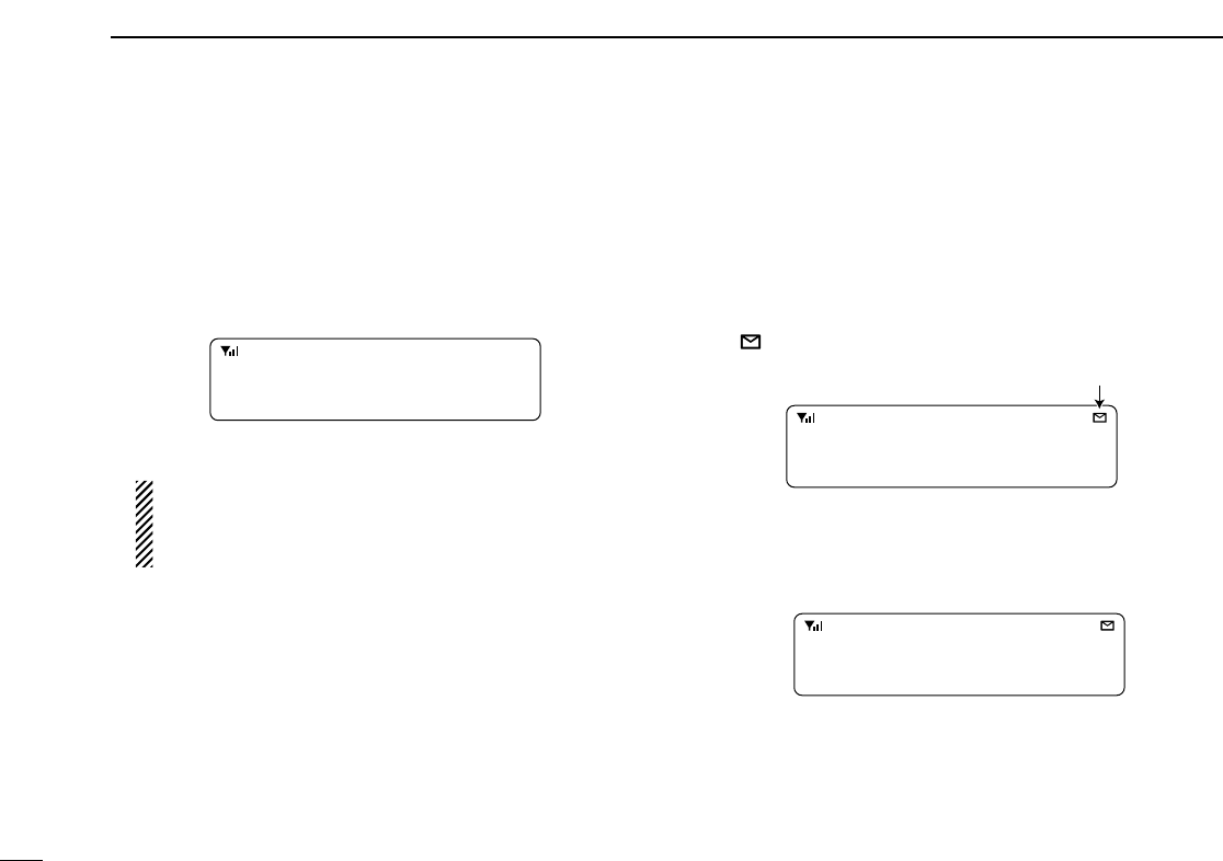
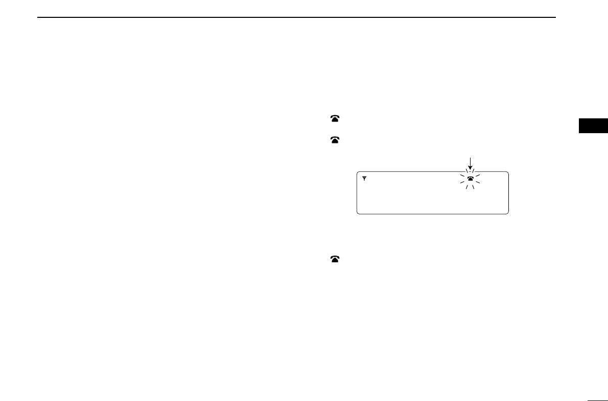
■Transmitting a call
DGroup call
qPush [CH Up] or [CH Down] to select the LTR system
channel or talk group.
wWhile pushing and holding [PTT], speak into the micro-
phone at a normal voice level after a beep is emitted.
• If an error beep is emitted, release [PTT]. After a while, repeat
step w.
• The beep can be turned OFF in User set mode.
DSelective call (DTMF call)
qPush [CH Up] or [CH Down] to select the LTR system
channel or talk group.
wPush [DTMF Autodial]— a DTMF encode channel
appears.
ePush [CH Up] or [CH Down] to select the desired DTMF
encode channel.
rPush [PTT] to transmit the selected DTMF code in the
selected DTMF channel.
• Push [DTMF Autodial] to cancel the DTMF transmission.
DPhone call
qSelect the phone channel of LTR system channel.
•“ ” appears.
wPush [Phone] (or push [PTT]).
•“ ” blinks.
ePush [DTMF Autodial] to make a phone call.
rAfter conversation is finished, push [Phone] to disconnect
the phone call.
•“ ” stops blinking.
002 ch-03
fH 173.7M
Blinks

1-1-32 Kamiminami, Hirano-ku, Osaka 547-0003, Japan
A-6565I-2EX
Printed in Japan
© 2006 Icom Inc.
Printed on recycled paper with soy ink.