ICOM orporated 298900 VHF Marine Transceiver User Manual Manual
ICOM Incorporated VHF Marine Transceiver Manual
UserManual.wiki
>
ICOM orporated
>
298900 User Manual
Manual
Navigation menu
Upload a User Manual
Namespaces
Wiki Guide
HTML
PDF
Info
Views
User Manual
Discussion / Help
Navigation
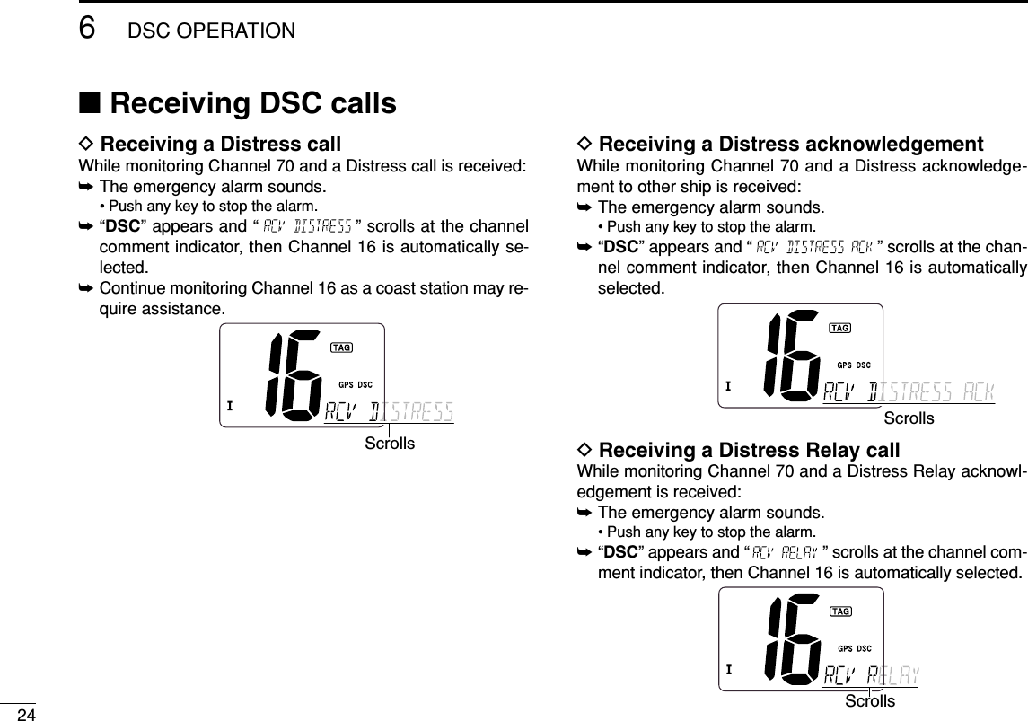
![iiIN CASE OF EMERGENCYIf your vessel requires assistance, contact other vessels andthe Coast Guard by sending a distress call on Channel 16.Or, transmit your distress call using digital selective calling onChannel 70.NOTEA WARNING STICKER is supplied with the transceiver.To comply with FCC regulations, this sticker must be affixed insuch a location as to be readily seen from the operating con-trols of the radio as in the diagram below. Make sure the cho-sen location is clean and dry before applying the sticker. (p. 32)EXAMPLEWARNING STICKERUSING DIGITAL SELECTIVE CALLING (Ch 70)DISTRESS CALL PROCEDURE1. While opening the key cover, push and hold[DISTRESS] for 5 sec. until you hear 5 short beepschange to one long beep.2. Wait for an acknowledgment from a coast station.• Channel 16 is automatically selected.3. Push and hold [PTT], then transmit the appropriateinformation as listed above.USING CHANNEL 16DISTRESS CALL PROCEDURE1. “MAYDAY MAYDAY MAYDAY.”2. “THIS IS ...............” (name of vessel)3. Your call sign or other indication of the vessel (AND 9-digit DSC ID if you have one).4. “LOCATED AT ...............” (your position)5. The nature of the distress and assistance required.6. Any other information which might facilitate the rescue.](https://usermanual.wiki/ICOM-orporated/298900/User-Guide-733082-Page-3.png)
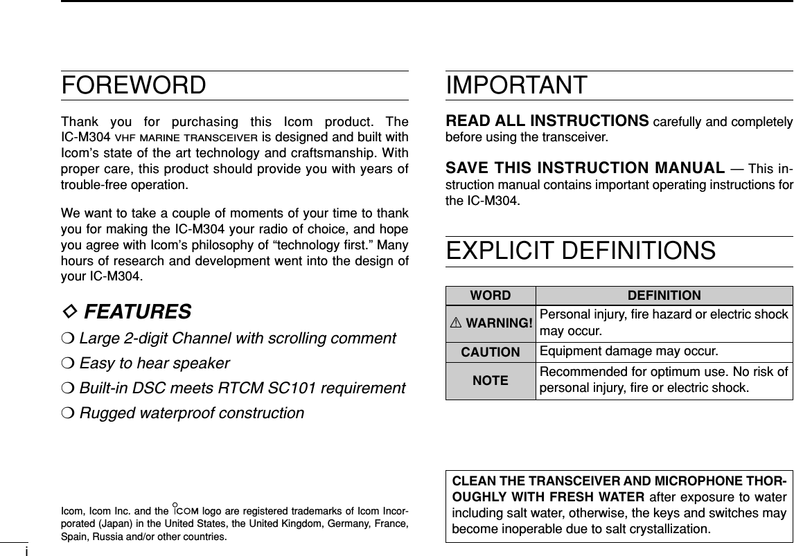
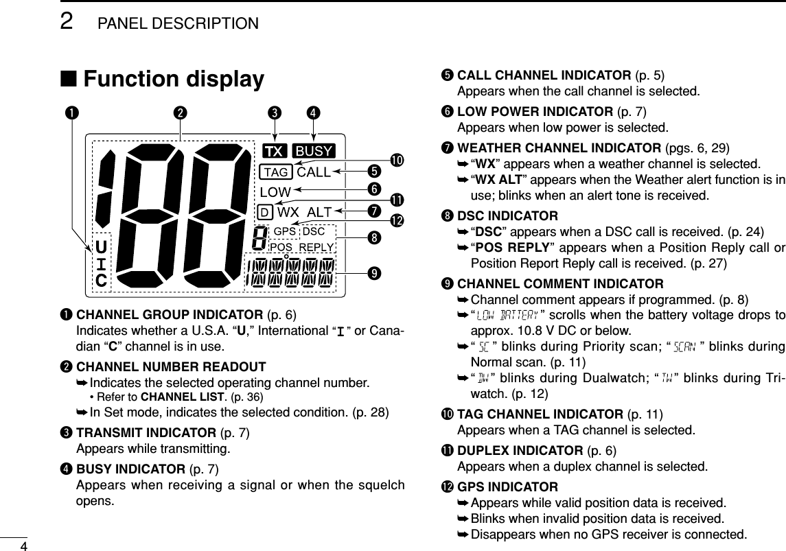
![2PANEL DESCRIPTION2■Front panelqCHANNEL UP/DOWN KEYS [YY]/[ZZ]•[U/I/C]➥Selects the operating channels, Set mode settings, etc.(pgs. 5, 6, 28)➥While pushing and holding [SCAN•TAG], push to adjustthe brightness of the LCD and key backlight. (p. 9)➥Selects one of three channel groups in sequence whenboth keys are pushed. (p. 6)• U.S.A., International and Canadian channels are available.➥While turning power ON, push and hold both keys to ac-tivate the AquaQuake function. (p. 9)wPOWER/VOLUME CONTROL [VOL] (p. 7)Rotate to turn the transceiver power ON and OFF and ad-justs the audio level.eSQUELCH CONTROL [SQL] (p. 7)Rotate to set the squelch threshold level.rCHANNEL 16/CALL CHANNEL KEY [!6•9]➥Push to select Channel 16. (p. 5)➥Push and hold for 1 sec. to select call channel. (p. 5)•“CALL” appears when the call channel is selected.➥Push and hold for 3 sec. to enter call channel program-ming condition when the call channel is selected. (p. 8)➥While pushing and holding [CH/WX•DUAL], push toenter the channel comments programming condition.(p. 8)➥Push to move the cursor forward. (p. 8)➥While turning power ON, push to enter Set mode. (p. 28)tCHANNEL/WEATHER CHANNEL KEY [CH/WX•DUAL]➥Selects and toggles the regular channel and weatherchannel when pushed momentarily. (p. 6)➥Push and hold for 1 sec. to start Dualwatch or Tri-watch.(p. 12)➥Push to stop Dualwatch or Tri-watch when either is acti-vated. (p. 12)➥Push to move the cursor backward. (p. 8)Speaker Function display (p. 4)qertyuiw](https://usermanual.wiki/ICOM-orporated/298900/User-Guide-733082-Page-8.png)
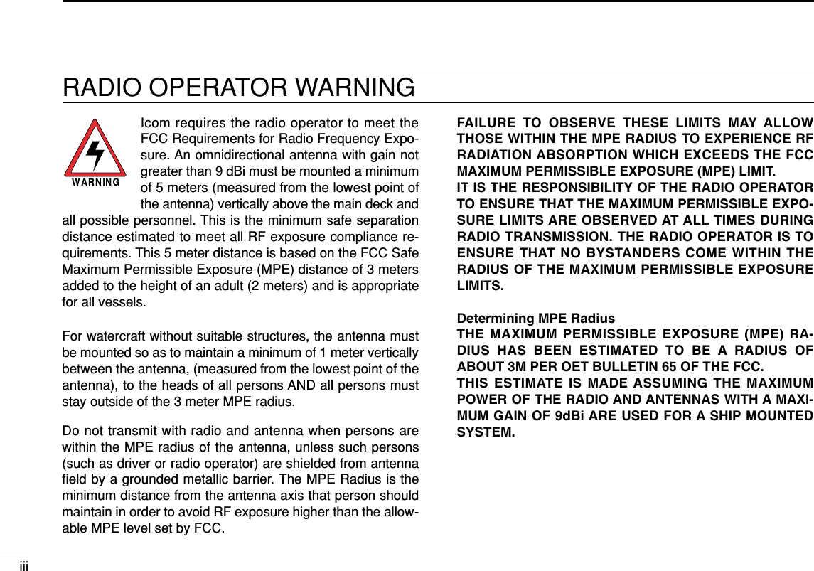
![32PANEL DESCRIPTIONySCAN KEY [SCAN•TAG] (p. 11)➥Push to start or stop the Normal or Priority scan.➥Push and hold for 1 sec. to set or clear the displayedchannel as a TAG (scanned) channel.➥While pushing and holding [HI/LO] on the microphone,push for 3 sec. to clear or set all TAG channels in theselected channel group.uDISTRESS KEY [DISTRESS] (p. 16)Push and hold for 5 sec. to transmit a Distress call.iDSC/POSITION KEY [DSC•POS]➥Push to enter DSC menu. (p. 13)➥Push and hold for 1 sec. to show the current positionfrom a GPS receiver. (p. 15)■MicrophoneqPTT SWITCH [PTT]Push and hold to transmit; release to receive. (p. 7)wCHANNEL UP/DOWN KEYS [YY]/[ZZ]➥Push either key to change the operating channel, Setmode settings, etc. (pgs. 5, 6, 28)➥When the Favorite channel function is turned ON, pusheither key to select the favorite channels in the selectedchannel group in sequence. (p. 30)eTRANSMIT POWER KEY [HI/LO]➥Push to toggle the power high and low. (p. 7)• Some channels are set to low power only.➥While pushing and holding [HI/LO], turn power ON totoggle the Microphone Lock function ON and OFF. (p. 9)Microphonewqe2](https://usermanual.wiki/ICOM-orporated/298900/User-Guide-733082-Page-9.png)
![53BASIC OPERATION23■Channel selectionïï Channel 16Channel 16 is the distress and safety channel. It is used forestablishing initial contact with a station and for emergencycommunications. Channel 16 is monitored during both Dual-watch and Tri-watch. While standing by, you must monitorChannel 16.➥Push [!6•9] momentarily to select Channel 16.➥Push [CH/WX•DUAL] to return to the condition before se-lecting Channel 16, or push [Y]or [Z]to select operatingchannel.Convenient!When the Favorite channel function is turned ON (p. 30),[Y]/[Z]keys on the microphone select the favorite channelsin the selected channel group in sequence when pushed.• The favorite channels are set by the TAG channel setting. (p. 11)ïï Channel 9 (Call channel)Each regular channel group has a separate leisure-use callchannel. The call channel is monitored during Tri-watch. Thecall channels can be programmed (p. 8) and are used to storeyour most often used channels in each channel group forquick recall.➥Push and hold [!6•9] for 1 sec. to select the call channel ofthe selected channel group.•“CALL” and call channel number appear.• Each channel group may have an independent call channel afterprogramming a call channel. (p. 8)➥Push [CH/WX•DUAL] to return to the condition before se-lecting call channel, or push [Y]or [Z]to select a channel.Pushfor 1 sec.ScrollsPushScrolls](https://usermanual.wiki/ICOM-orporated/298900/User-Guide-733082-Page-11.png)
![63BASIC OPERATIONïï U.S.A.,Canadian and international channelsThe IC-M304 is pre-programmed with 59 U.S.A., 59 interna-tional and 63 Canadian channels. These channel groups maybe specified for the operating area.qPush [CH/WX•DUAL] to select a regular channel.• If a weather channel appears, push [CH/WX•DUAL] again.wPush both [Y]and [Z]on the transceiver to change thechannel group, if necessary.• U.S.A., International and Canadian channel groups can be se-lected in sequence.ePush [Y]or [Z]to select a channel.• “ ” appears for duplex channels.ïï Weather channelsThe IC-M304 has 10 pre-programmed weather channels.These are used for monitoring broadcasts from NOAA (Na-tional Oceanographic and Atmospheric Administration.)The transceiver can automatically detect a weather alert toneon the selected weather channel while receiving the channelor during scanning. (p. 29)qPush [CH/WX•DUAL] once or twice to select a weatherchannel.•“WX” appears when a weather channel is selected.• “WX ALT” appears when the Weather alert function is in use.(p. 29)wPush [Y]or [Z]to select a channel.Push once or twiceWhen Weather alert is OFF. When Weather alert is ON.Push and](https://usermanual.wiki/ICOM-orporated/298900/User-Guide-733082-Page-12.png)
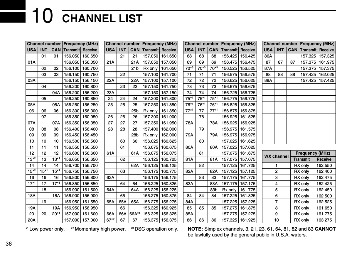
![73BASIC OPERATION3■Receiving and transmittingCAUTION: Transmitting without an antenna will damagethe transceiver.qRotate [VOL] to turn power ON.wSet the audio and squelch levels.➥Rotate [SQL] fully counterclockwise in advance.➥Rotate [VOL] to adjust the audio output level.➥Rotate [SQL] clockwise until the noise disappears.ePush both [Y]and [Z]on the transceiver several times toselect the desired channel group. (p. 6)rPush [Y]or [Z]to select a channel. (p. 5)• When receiving a signal, “ ” appears and audio is emittedfrom the speaker.• Further adjustment of [VOL] may be necessary.tPush [HI/LO] to select the output power if necessary.•“LOW” appears when low power is selected.• Choose low power for short range communications, choose highpower for longer distance communications.• Some channels are for low power only.yPush and hold [PTT] to transmit, then speak into the mi-crophone.• “ ” appears.• Channel 70 cannot be used for transmission other than DSC.uRelease [PTT] to receive.Simplex channels, 3, 21, 23, 61, 64, 81, 82 and 83 CAN-NOT be lawfully used by the general public in U.S.A. wa-ters.IMPORTANT: To maximize the readability of your trans-mitted signal, pause a few sec. after pushing [PTT], holdthe microphone 2 to 4 inches (5 to 10 cm) from your mouthand speak into the microphone at a normal voice level.✔NOTE for TOT (Time-out Timer) functionThe TOT function inhibits continuous transmission over a pre-set time period after the transmission starts.urtyq Microphonewre](https://usermanual.wiki/ICOM-orporated/298900/User-Guide-733082-Page-13.png)
![83BASIC OPERATION■Call channel programmingCall channel is used to select Channel 9 (default), however,you can program the call channel with your most often-usedchannels in each channel group for quick recall.qPush both [Y]and [Z]on the transceiver several times toselect the desired channel group (U.S.A., International orCanada) to be programmed.wPush and hold [!6•9] for 1 sec. to select the call channel ofthe selected channel group.•“CALL” and call channel number appear.ePush and hold [!6•9] againfor 3 sec. (until a long beepchanges to 2 short beeps)to enter call channel pro-gramming condition.• Channel number starts blink-ing.rPush [Y]or [Z]to selectthe desired channel.tPush [!6•9] to program thedisplayed channel as thecall channel.• Push [CH/WX•DUAL] to can-cel.• The channel number stopsblinking.■Channel commentsMemory channels can be labeled with a unique alphanumericID of up to 10 characters each.More than 6 characters comment scrolls automatically at thechannel comment indicator after the channel selection.Capital letters, small letters (except f, j, k, p, s, v, x, z), 0 to 9,some symbols (= ✱+ – . /) and space can be used.qSelect the desired channel.• Cancel Dualwatch, Tri-watch or Scan in advance.wWhile pushing [CH/WX•DUAL], push [!6•9] to edit thechannel comment.• A cursor and the first char-acter start blinking alter-nately.ePushing [Y]or [Z]to select the desired character.• Push [!6•9] or [CH/WX•DUAL] to move the cursor forward orbackward, respectively.rRepeat step eto input all characters.tPush [DSC•POS] to input and set the comment.• Push [SCAN•TAG] to cancel.• The cursor and the character stop blinking.yRepeat steps qto tto program other channel com-ments, if desired.](https://usermanual.wiki/ICOM-orporated/298900/User-Guide-733082-Page-14.png)
![93BASIC OPERATION3■Microphone lock functionThe microphone lock function electrically locks [Y]and [Z]keys on the supplied microphone. This prevents accidentalchannel changes and function access.➥While pushing and holding [HI/LO] on the microphone,turn power ON to toggle the Microphone lock function ONand OFF.■Display backlightingThe function display and keys can be backlit for better visibil-ity under low light conditions.➥While pushing and holding [SCAN•TAG], push [YY]or [ZZ]to adjust the brightness of the LCD and key backlight.• The backlight is selectable in 3 levels and OFF.■AquaQuake water drainingfunctionThe IC-M304 uses a new technology to clear water awayfrom the speaker grill: AquaQuake. AquaQuake helps drainwater away from the speaker housing (water that might oth-erwise muffle the sound coming from the speaker). The IC-M304 emits a vibrating noise when this function is beingused.➥While pushing and holding [Y]and [Z], turn power ON.• A low beep tone sounds while [Y]or [Z]keys are held to drainwater, regardless of [VOL] control setting.• The transceiver never accepts a key operation while theAquaQuake function is activated.• “ ” scrolls at the channel comment indicator.Scrolls[Y]/[Z]](https://usermanual.wiki/ICOM-orporated/298900/User-Guide-733082-Page-15.png)
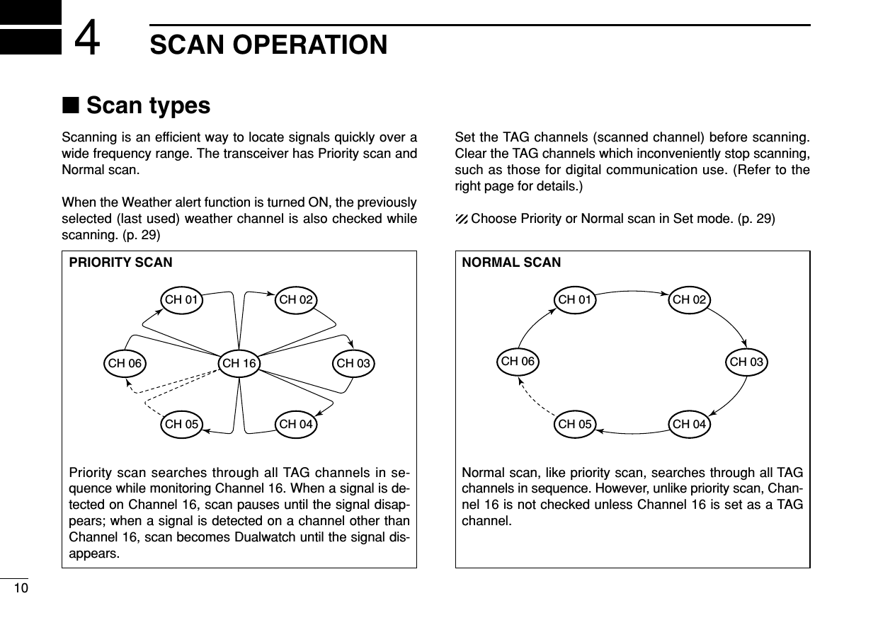
![114SCAN OPERATION4■Setting TAG channelsFor more efficient scanning, add desired channels as TAGchannels or clear the TAG for unwanted channels.Channels that are not tagged will be skipped during scanning.TAG channels can be assigned to each channel group(U.S.A., International and Canada) independently.qPush both [YY]and [ZZ]several times to select the desiredchannel group.wSelect the desired channel to be set as a TAG channel.ePush and hold [SCAN•TAG] for 1 sec. to set the displayedchannel as a TAG channel.• “ ” appears in the display.rTo cancel the TAG channel setting, repeat step e.• “ ” disappears.✔Clearing (or setting) all tagged channelsWhile pushing and holding [HI/LO] on the microphone, push[SCAN•TAG] for 3 sec. (until a long beep changes to 2 shortbeeps) to clear all TAG channels in the channel group.• Repeat above procedure to set all TAG channels.■Starting a scanSet scan type (Priority or Normal scan) and scan resumetimer in advance using Set mode. (p. 29)qPush both [YY]and [ZZ]several times to select the desiredchannel group, if desired.wSet TAG channels as described at left.eMake sure the squelch is closed to start a scan.rPush [SCAN•TAG] to start Priority or Normal scan.• “ ” blinks during Priority scan; “ ” blinks during Normalscan.• When a signal is detected, scan pauses until the signal disap-pears or resumes after pausing 5 sec. according to Set modesetting. (Channel 16 is still monitored during Priority scan.)• Push [Y]or [Z]to check the scanning TAG channels, to changethe scanning direction or resume the scan manually.• A beep tone sounds and “ ” blinks at the channel commentindicator when a signal is received on Channel 16 during Priorityscan.tTo stop the scan, push [SCAN•TAG].to stop the scanPushPushScan starts. When a signal is received.[Example]: Starting a normal scan.](https://usermanual.wiki/ICOM-orporated/298900/User-Guide-733082-Page-17.png)
![12DUALWATCH/TRI-WATCH5■DescriptionDualwatch monitors Channel 16 while you are receiving on another channel; Tri-watch monitors Channel 16 and thecall channel while receiving another channel. Dualwatch/Tri-watch are convenient for monitor Channel 16 when you areoperating on another channel.■OperationqSelect Dualwatch or Tri-watch in Set mode. (p. 29)wSelect the desired channel.ePush and hold [CH/WX•DUAL] for 1 sec. to start Dual-watch or Tri-watch.• “ ” blinks during Dualwatch; “ ” blinks during Tri-watch.• A beep tone sounds when a signal is received on Channel 16.rTo cancel Dualwatch or Tri-watch, push [CH/WX•DUAL].DUALWATCH/TRI-WATCH SIMULATION• If a signal is received on Channel 16, Dualwatch/Tri-watchpauses on Channel 16 until the signal disappears.• If a signal is received on the call channel during Tri-watch,Tri-watch becomes Dualwatch until the signal disappears.• To transmit on the selected channel during Dualwatch/Tri-watch, push and hold [PTT].Dualwatch Tri-watchCall channel[Example]: Operating Tri-watch on INT Channel 25Tri-watch starts.Signal is received on call channel.Signal is received on Channel 16 takes priority.Tri-watch resumes after the signal disappears.Push and holdfor 1 sec.](https://usermanual.wiki/ICOM-orporated/298900/User-Guide-733082-Page-18.png)
![136DSC OPERATION56■MMSI code programmingThe 9-digit MMSI (Maritime Mobile Service Identity: DSC selfID) code can be programmed at power ON.This code programming can be performed only twice.qTurn power OFF.wWhile pushing and holding [DSC•POS], turn power ON toenter MMSI code programming condition.eAfter the display appears, release [DSC•POS].• A cursor starts blinking.rEdit the specified MMSI code by pushing [Y]or [Z].• Push [!6•9] or [CH/WX•DUAL] to move the cursor forward orbackward, respectively.tInput 9-digit code, then push [DSC•POS] to set the code.• Returns to the normal operation.■MMSI code checkThe 9-digit MMSI (DSC self ID) code can be checked.qPush [DSC•POS] to enter the DSC menu.wPush [Y]or [Z]to select “ ” and push [DSC•POS].eCheck the 9-digit MMSI (DSC self ID) code.• The MMSI code is displayed and scrolls at the channel commentindicator.rPush [DSC•POS] to exit the DSC menu.MMSI (DSC self ID) code scrolls](https://usermanual.wiki/ICOM-orporated/298900/User-Guide-733082-Page-19.png)
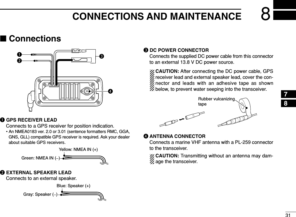
![146DSC OPERATION■DSC address IDA total of 30 DSC address IDs (9-digit) can be programmedand named with up to 5 characters.DProgramming address IDqPush [DSC•POS] to enter the DSC menu.wPush [Y]or [Z]to select “ ,” and push [DSC•POS].ePush [Y]or [Z]to select “ ,” and push [DSC•POS].rPush [Y]or [Z]to input 9-digit of the appropriate addressID.• Push [!6•9] or [CH/WX•DUAL] to move the cursor forward orbackward, respectively.• Push [SCAN•TAG] to cancel and exit the condition.1st digit ‘0’ is fixed for a group ID. When you input 1st digit ‘0’and other 8 digits, the ID is automatically registered as a groupID.tAfter inputting 9-digit ID, push [DSC•POS] to input 5 char-acters ID name using [Y]or [Z].• Push [!6•9] or [CH/WX•DUAL] to move the cursor forward orbackward, respectively.• Push [SCAN•TAG] to cancel and exit the condition.yPush [DSC•POS] to program and exit the DSC menu.Scrolls](https://usermanual.wiki/ICOM-orporated/298900/User-Guide-733082-Page-20.png)
![156DSC OPERATION6DDeleting address IDqPush [DSC•POS] to enter the DSC menu.wPush [Y]or [Z]to select “ ” and push [DSC•POS].ePush [Y]or [Z]to select “ ”, then push [DSC•POS].• When no address ID is programmed, “ ” is displayed.rPush [Y]or [Z]to select the desired ID name for deletingand push [DSC•POS].• “ ” appears.tPush [DSC•POS] to delete the address ID and exit theDSC menu.■Position indicationWhen a GPS receiver (NMEA0183 ver. 2.0 or 3.01) is con-nected, the transceiver indicates the current position data inseconds of accuracy.A NMEA0183 ver. 2.0 or 3.01 (sentence formatters RMC,GGA, GNS, GLL) compatible GPS receiver is required. Askyour dealer about suitable GPS receivers.➥Push and hold [DSC•POS] for 1 sec. to display the currentposition.• ‘Latitude’ and ‘Longitude’ scroll in sequence at the channel com-ment indicator.• “ ” scrolls when no GPS is connected.• When the connecting GPS receiver is compatible withseveral sentence formatters, the order of input prece-dence is ‘RMC,’ ‘GGA,’ ‘GNS’ and ‘GLL.’• “GPS” blinks when the GPS data is invalid.ScrollsScrolls](https://usermanual.wiki/ICOM-orporated/298900/User-Guide-733082-Page-21.png)
![166DSC OPERATION■Distress callA Distress call should be transmitted if, in the opinion of theMaster, the ship or a person is in distress and requires imme-diate assistance.NEVER USE THE DISTRESS CALL WHEN YOURSHIP OR A PERSON IS NOT IN AN EMERGENCY.A DISTRESS CALL CAN BE USED ONLY WHENIMMEDIATE HELP IS NEEDED.qConfirm no Distress call is being received.wWhile opening the key cover, push [DISTRESS] for 5 sec.to transmit the Distress call.• Emergency channel (Channel 70) is automatically selected andthe Distress call is transmitted.eAfter transmitting the call, the transceiver waits for an ac-knowledgment call on Channel 70.• The Distress call is automatically transmitted every 3.5 to 4.5minutes.• “ ” scrolls at the channel comment indicator.rAfter receiving the acknowledgment, reply using the mi-crophone.• “ ” scrolls at the channel comment indicator.➥A distress alert contains;• Kinds of distress : Undesignated distress• Position data : GPS position data held for 23.5 hrs. or untilthe power is turned OFF.➥The Distress call is repeated every 3.5–4.5 min., untilreceiving an ‘acknowledgement.’➥Push and hold [DISTRESS] for 5 sec. to transmit a re-newed Distress call, if desired.➥Push any key except [DISTRESS] to cancel the ‘Call repeat’ mode.ScrollsScrolls](https://usermanual.wiki/ICOM-orporated/298900/User-Guide-733082-Page-22.png)
![176DSC OPERATION6■Transmitting DSC callsTo ensure correct operation of the DSC function, pleasemake sure you set the squelch correctly. (p. 7)DTransmitting Individual callThe Individual call function allows you to transmit a DSC sig-nal to a specific ship only.qPush [DSC•POS] to enter the DSC menu.• “ ” scrolls at the channel comment indicator.wPush [DSC•POS] to select the desired pre-programmed in-dividual address using [Y]or [Z], then push [DSC•POS].• The ID code for the individual call must be set in advance.(p. 14)ePush [Y]or [Z] to select a desired intership channel, push[DSC•POS].• Intership channels are already preset into the transceiver in rec-ommended order.• Channel 70 is selected and “ ” appears after pushing[DSC•POS].rPush [DSC•POS] to transmit the Individual call.• If Channel 70 is busy, the transceiver stands by until the channelbecomes clear.• Routine category only is available.When Ch 70 is busy.Push [DSC POS] to transmit DSC call.Scrolls](https://usermanual.wiki/ICOM-orporated/298900/User-Guide-733082-Page-23.png)
![186DSC OPERATIONtAfter transmitting the Individual call, standby on Channel70 until an acknowledgement is received.• “ ” scrolls at the channel comment indicator.yWhen the acknowledgement ‘Able to comply’ is received,the specified channel (in step e) is selected with beepsautomatically. Or, when the acknowledgement ‘Unable tocomply’ is received, the display returns to the operatedchannel (before entering the DSC menu) with beeps.• “ ” or “ ” scrolls at the channelcomment indicator.uPush and hold [PTT] to communicate your message to theresponding ship.DTransmitting Individual acknowledgementWhen receiving an Individual call, you can transmit an ac-knowledgement (‘Able to comply’ or ‘Unable to comply’) byusing the on screen prompts (see page 25 for details). Youcan also send an acknowledgement through the menu sys-tem as follows.qPush [DSC•POS] to enter the DSC menu.wPush [Y]or [Z] to select “ ” and push [DSC•POS].• “ ” item appears after an Individual call is received.• “ ” item disappears if another call is received after theIndividual call.• The Individual acknowledgement can be transmitted to the lastreceived individual call only.ePush [Y]or [Z]to select the acknowledgement “ ” or“.”ScrollsScrolls‘Able to comply’is receivedScrolls](https://usermanual.wiki/ICOM-orporated/298900/User-Guide-733082-Page-24.png)
![196DSC OPERATION6rPush [DSC•POS] to enter selected Individual call ac-knowledgement.• “ ” appears at the channel comment indicator.tPush [DSC•POS] to transmit the acknowledgement to theselected station.yAfter the Individual acknowledgement has been transmit-ted, the display changes to the channel specified by thecalling station automatically when “ ” is selected.DTransmitting Group callThe Group call function allows you to transmit a DSC signalto a specific group only.qPush [DSC•POS] to enter the DSC menu.wPush [Y]or [Z] to select “ ,” and push [DSC•POS].ePush [Y]or [Z] to select the desired pre-programmedgroup address, and push [DSC•POS].• The ID code for the group call must be set in advance. (p. 14)Scrolls](https://usermanual.wiki/ICOM-orporated/298900/User-Guide-733082-Page-25.png)
![rPush [Y]or [Z] to select the desired intership channel,and push [DSC•POS].• Channel 70 is selected and “ ” appears.tPush [DSC•POS] to transmit the Group call.• If Channel 70 is busy, the transceiver stands by until the channelbecomes clear.• Routine category only is available.yAfter the Group call has been transmitted, the displaychanges to the previously specified channel.uPush and hold [PTT] to communicate your message to theresponding ship.Scrolls206DSC OPERATION](https://usermanual.wiki/ICOM-orporated/298900/User-Guide-733082-Page-26.png)
![216DSC OPERATION6DTransmitting All Ships callLarge ships use Channel 70 as their ‘listening channel.’When you want to announce a message to these ships, usethe ‘All Ships call’ function.qPush [DSC•POS] to enter the DSC menu.wPush [Y]or [Z]to select “ .”ePush [DSC•POS] to enter the standby condition for AllShips call.• Channel 70 is selected and “ ” appears.rPush [DSC•POS] to transmit the All Ships call.• Routine category only is available.• Low power is selected.tAfter the All Ships call has been transmitted, the displaychanges to Channel 16 automatically.ScrollsScrolls](https://usermanual.wiki/ICOM-orporated/298900/User-Guide-733082-Page-27.png)
![226DSC OPERATIONDTransmitting Position Request callTransmit a Position Request call when you want to know aspecified ship’s current position, etc.qPush [DSC•POS] to enter the DSC menu.wPush [Y]or [Z] to select “ ,” then push[DSC•POS].ePush [Y]or [Z] to select the desired pre-programmed in-dividual address.• The ID code for position request must be set in advance. (p. 14)rPush [DSC•POS] to enter the standby condition for Posi-tion Request call.• Channel 70 is selected and “ ” appears.tPush [DSC•POS] to transmit the Position Request call.yAfter the Position Request call has been transmitted, thefollowing indication is displayed.• “ ” scrolls at the channel comment indicator.uPush any key to exit the condition and return to the normaloperation.ScrollsScrolls](https://usermanual.wiki/ICOM-orporated/298900/User-Guide-733082-Page-28.png)
![236DSC OPERATION6DTransmitting Position Report callTransmit a Position Report call when you want to announceyour own position to a specific ship and to get an answer, etc.qPush [DSC•POS] to enter the DSC menu.wPush [Y]or [Z]to select “ ,” and push[DSC•POS].ePush [Y]or [Z] to select the desired pre-programmed in-dividual address.• The ID code for the position report call can be set in advance.(p. 14)rPush [DSC•POS] to enter the standby condition for Posi-tion Report call.• Channel 70 is selected and “ ” appears.tPush [DSC•POS] to transmit the Position Report call.yAfter the Position Report call has been transmitted, standby on Channel 70 until an acknowledgement is received.• “ ” scrolls at the channel comment indicator.uPush any key to exit the condition and return to the normaloperation.ScrollsScrolls](https://usermanual.wiki/ICOM-orporated/298900/User-Guide-733082-Page-29.png)
![256DSC OPERATION6DReceiving an Individual callWhile monitoring Channel 70 and an Individual call is re-ceived:➥The emergency alarm or beeps sound depending on thereceived category.➥“DSC” appears and “ ” scrolls at the channelcomment indicator.➥Push any key to stop beep, then push [DSC•POS] to replythe call and select the channel specified by the calling sta-tion for voice communication (depending on your replyingcondition see p. 18 for individual acknowledgement callprocedure for details.); push any other key to ignore the In-dividual call.DReceiving a Group callWhile monitoring Channel 70 and a Group call is received:➥The emergency alarm or beeps sound depending on thereceived category.➥“DSC” appears and “ ” scrolls at the channelcomment indicator.➥Push any key to stop beep, then push [DSC•POS] to se-lect the channel specified by the calling station for voicecommunication; push any other key to ignore the Groupcall.ScrollsScrolls](https://usermanual.wiki/ICOM-orporated/298900/User-Guide-733082-Page-31.png)
![266DSC OPERATIONDReceiving an All Ships callWhile monitoring Channel 70 and an All Ships call is received:➥The emergency alarm sounds when the category is ‘Dis-tress’ or ‘Urgency’; 2 beeps sound for other categories.➥“DSC” appears and “ ” scrolls at the channelcomment indicator.➥Push any key to stop beep, then push [DSC•POS] to mon-itor channel 16 for an announcement from the calling ves-sel, push any other key to ignore the call.DReceiving a Geographical Area callWhile monitoring Channel 70 and a Geographical Area call(for the area you are in) is received:➥The emergency alarm or beeps sound depending on thereceived category.➥“DSC” appears and “ ” scrolls at the chan-nel comment indicator.➥Push any key to stop the beep, then push [DSC•POS] tochange to the channel specified by the calling station forvoice communication; push any other key to ignore the Ge-ographical Area call.➥Monitor the selected channel for an announcement fromthe calling station.When no GPS receiver is connected or if there is a prob-lem with the connected receiver, all Geographical Areacalls are received, regardless of your position.ScrollsScrolls](https://usermanual.wiki/ICOM-orporated/298900/User-Guide-733082-Page-32.png)
![276DSC OPERATION6DReceiving a Position Request callWhile monitoring Channel 70 and a Position Request call isreceived:➥“DSC” appears and “ ” scrolls at the chan-nel comment indicator.➥Push any key to stop the beep, then push [DSC•POS] toreply to the call; push any other key to ignore the call.DReceiving a Position Report callWhile monitoring Channel 70 and a Position Report call is re-ceived:➥“DSC” appears and “ ” scrolls at the chan-nel comment indicator.➥Push any key to stop the beep, then push [DSC•POS] toreply to the call; push any other key to ignore the call.• The ‘Latitude’ and ‘Longitude’ from the called station is displayedand scrolled automatically in order of Latitude co-ordinates andthen Longitude co-ordinates.DReceiving a Position Reply callWhile monitoring Channel 70 and a Position Reply call is re-ceived:➥“DSC” and “POS REPLY” appear in the display.• The ‘Latitude’ and ‘Longitude’ from the called station is displayedand scrolled automatically in order of Latitude co-ordinates andthen Longitude co-ordinates.➥Push any key to stop the beep.DReceiving a Position Report Reply callWhile monitoring Channel 70 and a Position Report Reply callis received:➥“DSC” and “POS REPLY” appear in the display.• The ‘Latitude’ and ‘Longitude’ you have sent is displayed andscrolled automatically in order of Latitude co-ordinates and thenLongitude co-ordinates.➥Push any key to stop the beep.ScrollsScrollsScrollsScrolls](https://usermanual.wiki/ICOM-orporated/298900/User-Guide-733082-Page-33.png)
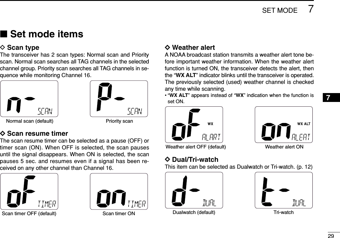
![28SET MODE7■Set mode programmingSet mode is used to change the conditions of the trans-ceiver’s functions: Scan type (Normal or Priority,) Scan re-sume timer, Weather alert, Dual/Tri-watch, DSC watch, Beeptone, Auto acknowledgement and Favorite channel function.Available functions may differ depending on dealer setting.DSet mode operationqTurn power OFF.wWhile pushing [!6•9], turn power ON to enter Set mode.• “ ” appears at the channel comment indicator.eAfter the display appears, release [!6•9].rPush [!6•9] to select the desired item, if necessary.tPush [Y]or [Z]to select the desired condition of the item.yTurn power OFF, then ON again to exit Set mode.• Beep toneStarting item• Scan type • Scan resume timer • Weather alert • Dual/Tri-watch• DSC watch• Auto acknowledgementScrolls• Favorite channel functionScrolls ScrollsPushDSet mode construction](https://usermanual.wiki/ICOM-orporated/298900/User-Guide-733082-Page-34.png)
![307SET MODEDDDSC watchDSC watch monitors Channel 70 while you are receiving an-other channel.If a distress signal is received on Channel 70, the transceivermonitors Channel 16 and 70 alternately until the distress sig-nal disappears. If a signal is received on another channel,DSC watch pauses until the signal disappears.This function may not be available for some channelgroups depending on dealer setting.• “ ” scrolls at the channel comment indicator.DDBeep toneYou can select silent operation by turning beep tones OFF oryou can have confirmation beeps sound at the push of a keyby turning beep tones ON.DDAutomatic acknowledgementThis item sets the Automatic acknowledgement function ONor OFF.When Position Request or Position Report call is received,transceiver automatically transmits Position Request Reply orPosition Report Reply call, respectively.• “ ” scrolls at the channel comment indicator.DDFavorite channelThis item sets the Favorite channel function ON or OFF.The favorite channel is programmed by the TAG channel set-ting (p. 11).When the Favorite channel function is turned ON, [YY]/[ZZ]keys on the microphone select the favorite channels in theselected channel group in sequence when pushed.• “ ” scrolls at the channel comment indicator.Favorite CH ON (default) Favorite CH OFFAuto acknowledgementOFF (default)Auto acknowledgementONBeep tone ON (default) Beep tone OFFDSC watch OFF (default) DSC watch ON](https://usermanual.wiki/ICOM-orporated/298900/User-Guide-733082-Page-36.png)
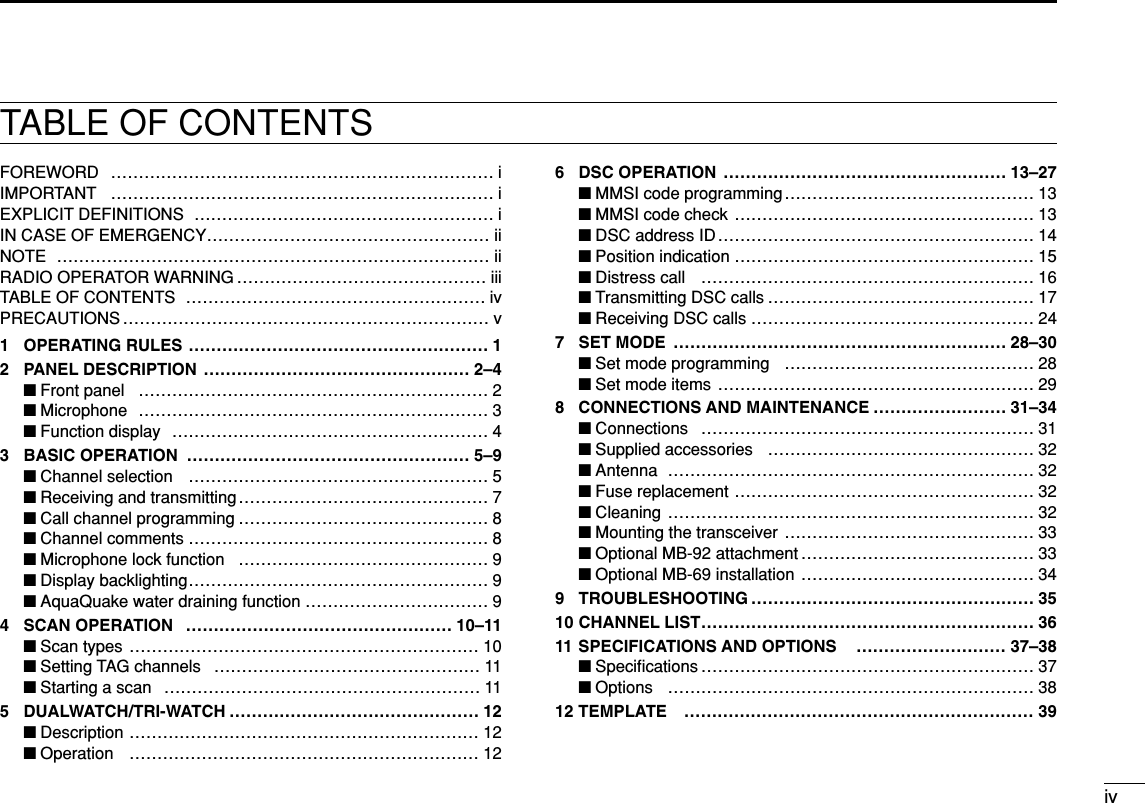
![359TROUBLESHOOTINGPROBLEM POSSIBLE CAUSE SOLUTION REF.No sound from speaker. • Squelch level is too high.• Volume level is too low.• Speaker has been exposed to water.p. 7p. 7—• Set squelch to the threshold point.• Set [VOL] to a suitable level.• Drain water from the speaker.The transceiver doesnot turn ON.• Bad connection to the power supply. p. 31• Check the connection to the transceiver.Transmitting is impossi-ble, or high power cannot be selected.• Some channels are for low power or re-ceive only.• The output power is set to low.pgs. 5,6, 36p. 7• Change channels.• Push [HI/LO] on the microphone to selecthigh power.Scan does not start. • “TAG” channel is not programmed. • Set the desired channels as “TAG” channels. p. 11No beeps. • Beep tones are turned OFF. • Turn the beep tone ON in Set mode. p. 30Distress call cannot betransmitted.• MMSI (DSC self ID) code is not pro-grammed.• Program the MMSI (DSC self ID) code. p. 1389](https://usermanual.wiki/ICOM-orporated/298900/User-Guide-733082-Page-41.png)