ICOM orporated 298900 VHF Marine Transceiver User Manual Manual
ICOM Incorporated VHF Marine Transceiver Manual
Manual

INSTRUCTION MANUAL
iM304
VHF MARINE TRANSCEIVER

i
FOREWORD
Thank you for purchasing this Icom product. The
IC-M304
VHF MARINE TRANSCEIVER
is designed and built with
Icom’s state of the art technology and craftsmanship. With
proper care, this product should provide you with years of
trouble-free operation.
We want to take a couple of moments of your time to thank
you for making the IC-M304 your radio of choice, and hope
you agree with Icom’s philosophy of “technology first.” Many
hours of research and development went into the design of
your IC-M304.
D
FEATURES
❍Large 2-digit Channel with scrolling comment
❍Easy to hear speaker
❍Built-in DSC meets RTCM SC101 requirement
❍Rugged waterproof construction
IMPORTANT
READ ALL INSTRUCTIONS carefully and completely
before using the transceiver.
SAVE THIS INSTRUCTION MANUAL — This in-
struction manual contains important operating instructions for
the IC-M304.
EXPLICIT DEFINITIONS
WORD DEFINITION
RWARNING!
CAUTION
NOTE
Personal injury, fire hazard or electric shock
may occur.
Equipment damage may occur.
Recommended for optimum use. No risk of
personal injury, fire or electric shock.
CLEAN THE TRANSCEIVER AND MICROPHONE THOR-
OUGHLY WITH FRESH WATER after exposure to water
including salt water, otherwise, the keys and switches may
become inoperable due to salt crystallization.
Icom, Icom Inc. and the logo are registered trademarks of Icom Incor-
porated (Japan) in the United States, the United Kingdom, Germany, France,
Spain, Russia and/or other countries.
ii
IN CASE OF EMERGENCY
If your vessel requires assistance, contact other vessels and
the Coast Guard by sending a distress call on Channel 16.
Or, transmit your distress call using digital selective calling on
Channel 70.
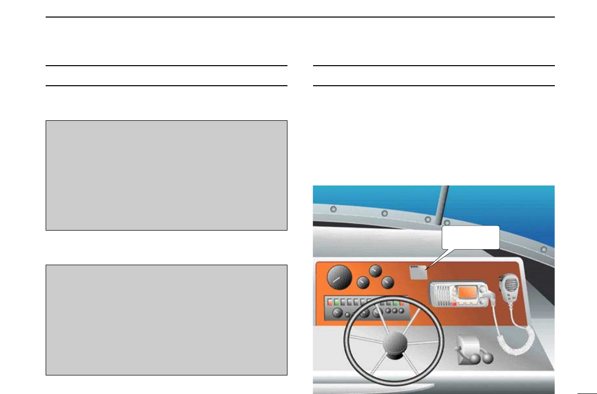
NOTE
A WARNING STICKER is supplied with the transceiver.
To comply with FCC regulations, this sticker must be affixed in
such a location as to be readily seen from the operating con-
trols of the radio as in the diagram below. Make sure the cho-
sen location is clean and dry before applying the sticker.
(p. 32)
EXAMPLE
WARNING
STICKER
USING DIGITAL SELECTIVE CALLING (Ch 70)
DISTRESS CALL PROCEDURE
1. While opening the key cover, push and hold
[DISTRESS] for 5 sec. until you hear 5 short beeps
change to one long beep.
2. Wait for an acknowledgment from a coast station.
• Channel 16 is automatically selected.
3. Push and hold [PTT], then transmit the appropriate
information as listed above.
USING CHANNEL 16
DISTRESS CALL PROCEDURE
1. “MAYDAY MAYDAY MAYDAY.”
2. “THIS IS ...............” (name of vessel)
3. Your call sign or other indication of the vessel (AND 9-
digit DSC ID if you have one).
4. “LOCATED AT ...............” (your position)
5. The nature of the distress and assistance required.
6. Any other information which might facilitate the rescue.

iii
RADIO OPERATOR WARNING
Icom requires the radio operator to meet the
FCC Requirements for Radio Frequency Expo-
sure. An omnidirectional antenna with gain not
greater than 9 dBi must be mounted a minimum
of 5 meters (measured from the lowest point of
the antenna) vertically above the main deck and
all possible personnel. This is the minimum safe separation
distance estimated to meet all RF exposure compliance re-
quirements. This 5 meter distance is based on the FCC Safe
Maximum Permissible Exposure (MPE) distance of 3 meters
added to the height of an adult (2 meters) and is appropriate
for all vessels.
For watercraft without suitable structures, the antenna must
be mounted so as to maintain a minimum of 1 meter vertically
between the antenna, (measured from the lowest point of the
antenna), to the heads of all persons AND all persons must
stay outside of the 3 meter MPE radius.
Do not transmit with radio and antenna when persons are
within the MPE radius of the antenna, unless such persons
(such as driver or radio operator) are shielded from antenna
field by a grounded metallic barrier. The MPE Radius is the
minimum distance from the antenna axis that person should
maintain in order to avoid RF exposure higher than the allow-
able MPE level set by FCC.
WARNING
FAILURE TO OBSERVE THESE LIMITS MAY ALLOW
THOSE WITHIN THE MPE RADIUS TO EXPERIENCE RF
RADIATION ABSORPTION WHICH EXCEEDS THE FCC
MAXIMUM PERMISSIBLE EXPOSURE (MPE) LIMIT.
IT IS THE RESPONSIBILITY OF THE RADIO OPERATOR
TO ENSURE THAT THE MAXIMUM PERMISSIBLE EXPO-
SURE LIMITS ARE OBSERVED AT ALL TIMES DURING
RADIO TRANSMISSION. THE RADIO OPERATOR IS TO
ENSURE THAT NO BYSTANDERS COME WITHIN THE
RADIUS OF THE MAXIMUM PERMISSIBLE EXPOSURE
LIMITS.
Determining MPE Radius
THE MAXIMUM PERMISSIBLE EXPOSURE (MPE) RA-
DIUS HAS BEEN ESTIMATED TO BE A RADIUS OF
ABOUT 3M PER OET BULLETIN 65 OF THE FCC.
THIS ESTIMATE IS MADE ASSUMING THE MAXIMUM
POWER OF THE RADIO AND ANTENNAS WITH A MAXI-
MUM GAIN OF 9dBi ARE USED FOR A SHIP MOUNTED
SYSTEM.

iv
FOREWORD …………………………………………………………… i
IMPORTANT …………………………………………………………… i
EXPLICIT DEFINITIONS ……………………………………………… i
IN CASE OF EMERGENCY…………………………………………… ii
NOTE …………………………………………………………………… ii
RADIO OPERATOR WARNING ……………………………………… iii
TABLE OF CONTENTS ……………………………………………… iv
PRECAUTIONS ………………………………………………………… v
1 OPERATING RULES ……………………………………………… 1
2 PANEL DESCRIPTION ………………………………………… 2–4
■Front panel ……………………………………………………… 2
■Microphone ……………………………………………………… 3
■Function display ………………………………………………… 4
3 BASIC OPERATION …………………………………………… 5–9
■Channel selection ……………………………………………… 5
■Receiving and transmitting……………………………………… 7
■Call channel programming ……………………………………… 8
■Channel comments ……………………………………………… 8
■Microphone lock function ……………………………………… 9
■Display backlighting……………………………………………… 9
■AquaQuake water draining function …………………………… 9
4 SCAN OPERATION ………………………………………… 10–11
■Scan types ……………………………………………………… 10
■Setting TAG channels ………………………………………… 11
■Starting a scan ………………………………………………… 11
5 DUALWATCH/TRI-WATCH ……………………………………… 12
■Description ……………………………………………………… 12
■Operation ……………………………………………………… 12
6 DSC OPERATION …………………………………………… 13–27
■MMSI code programming……………………………………… 13
■MMSI code check ……………………………………………… 13
■DSC address ID………………………………………………… 14
■Position indication ……………………………………………… 15
■Distress call …………………………………………………… 16
■Transmitting DSC calls ………………………………………… 17
■Receiving DSC calls …………………………………………… 24
7 SET MODE …………………………………………………… 28–30
■Set mode programming ……………………………………… 28
■Set mode items ………………………………………………… 29
8 CONNECTIONS AND MAINTENANCE …………………… 31–34
■Connections …………………………………………………… 31
■Supplied accessories ………………………………………… 32
■Antenna ………………………………………………………… 32
■Fuse replacement ……………………………………………… 32
■Cleaning ………………………………………………………… 32
■Mounting the transceiver ……………………………………… 33
■Optional MB-92 attachment …………………………………… 33
■Optional MB-69 installation …………………………………… 34
9 TROUBLESHOOTING …………………………………………… 35
10 CHANNEL LIST…………………………………………………… 36
11 SPECIFICATIONS AND OPTIONS ……………………… 37–38
■Specifications …………………………………………………… 37
■Options ………………………………………………………… 38
12 TEMPLATE ……………………………………………………… 39
TABLE OF CONTENTS

v
PRECAUTIONS
RWARNING! NEVER connect the transceiver to an AC
outlet. This may pose a fire hazard or result in an electric
shock.
CAUTION: Changes or modifications to this device, not ex-
pressly approved by Icom Inc., could void your authority to
operate this device under FCC regulations.
NEVER connect the transceiver to a power source of more
than 16 V DC or use reverse polarity. This will ruin the trans-
ceiver.
NEVER cut the DC power cable between the DC plug and
fuse holder. If an incorrect connection is made after cutting,
the transceiver may be damaged.
NEVER place the transceiver where normal operation of the
vessel may be hindered or where it could cause bodily injury.
KEEP the transceiver at least 3.3 ft (1 m) away from the
ship’s navigation compass.
DO NOT use or place the transceiver in areas with temper-
atures below –4°F (–20°C) or above +140°F (+60°C) or, in
areas subject to direct sunlight, such as the dashboard.
AVOID the use of chemical agents such as benzine or al-
cohol when cleaning, as they may damage the transceiver
surfaces.
BE CAREFUL! The transceiver rear panel will become
hot when operating continuously for long periods.
Place the transceiver in a secure place to avoid inadvertent
use by children.
BE CAREFUL! The transceiver employs waterproof con-
struction, which corresponds to IPX7 of the international stan-
dard IEC 60529 (2001). However, once the transceiver has
been dropped, waterproofing cannot be guaranteed due to
the fact that the case may be cracked, or the waterproof seal
damaged, etc.

1
1
OPERATING RULES
DDPRIORITIES
• Read all rules and regulations pertaining to priorities and
keep an up-to-date copy handy. Safety and distress calls
take priority over all others.
• You must monitor Channel 16 when you are not operating
on another channel.
• False or fraudulent distress signals are prohibited and pun-
ishable by law.
DDPRIVACY
• Information overheard but not intended for you cannot law-
fully be used in any way.
• Indecent or profane language is prohibited.
DDRADIO LICENSES
(1) SHIP STATION LICENSE
You must have a current radio station license before using the
transceiver. It is unlawful to operate a ship station which is not
licensed.
Inquire through your dealer or the appropriate government
agency for a Ship-Radiotelephone license application. This
government-issued license states the call sign which is your
craft’s identification for radio purposes.
(2) OPERATOR’S LICENSE
A Restricted Radiotelephone Operator Permit is the license
most often held by small vessel radio operators when a radio
is not required for safety purposes.
The Restricted Radiotelephone Operator Permit must be
posted or kept with the operator. Only a licensed radio opera-
tor may operate a transceiver.
However, non-licensed individuals may talk over a transceiver
if a licensed operator starts, supervises, ends the call and
makes the necessary log entries.
Keep a copy of the current government rules and regulations
handy.
Radio license for boaters (U.S.A. only)
The Telecommunications Act of 1996 permits recreational
boaters to have and use a VHF marine radio, EPIRB, and
marine radar without having an FCC ship station license.
Boaters traveling on international voyages, having an HF
single sideband radiotelephone or marine satellite termi-
nal, or required to carry a marine radio under any other
regulation must still carry an FCC ship station license. For
further information, see the FCC Ship Radio Stations Fact
Sheet.
1
2
PANEL DESCRIPTION
2
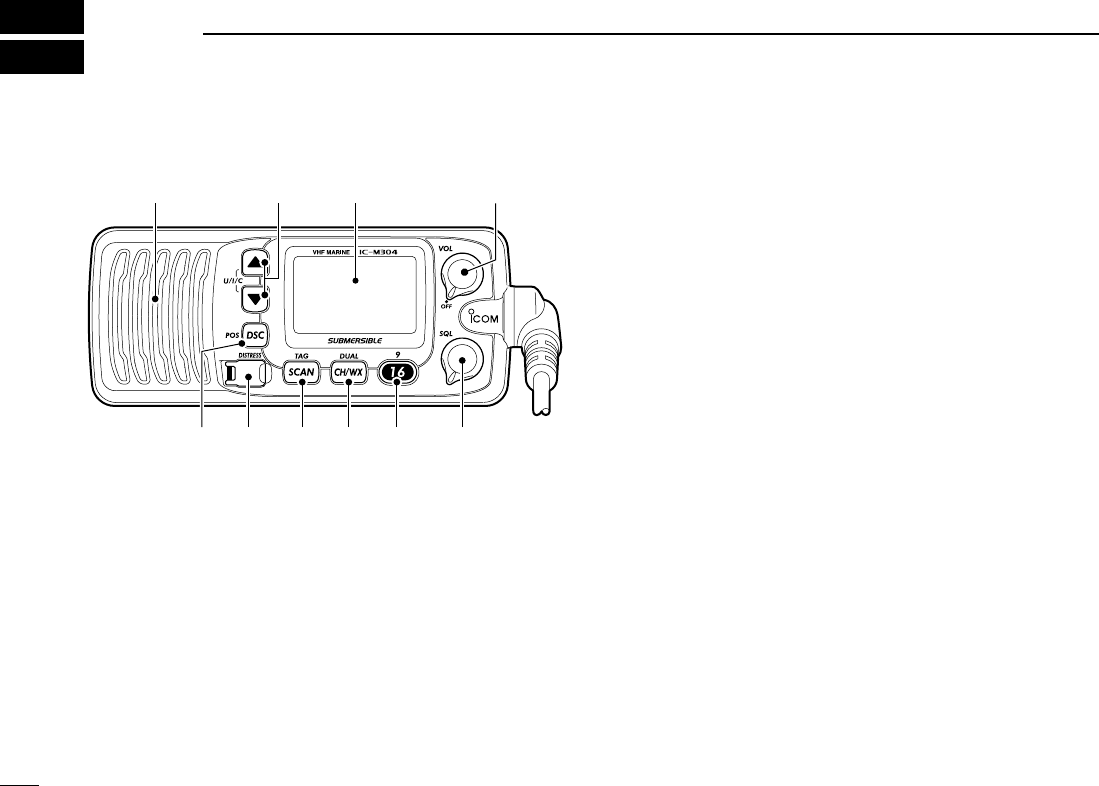
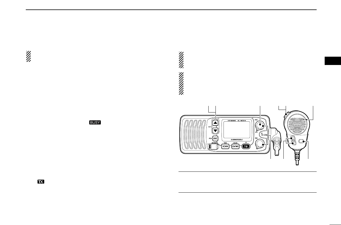
■Front panel
qCHANNEL UP/DOWN KEYS [YY]/[ZZ]•[U/I/C]
➥Selects the operating channels, Set mode settings, etc.
(pgs. 5, 6, 28)
➥While pushing and holding [SCAN•TAG], push to adjust
the brightness of the LCD and key backlight. (p. 9)
➥Selects one of three channel groups in sequence when
both keys are pushed. (p. 6)
• U.S.A., International and Canadian channels are available.
➥While turning power ON, push and hold both keys to ac-
tivate the AquaQuake function. (p. 9)
wPOWER/VOLUME CONTROL [VOL] (p. 7)
Rotate to turn the transceiver power ON and OFF and ad-
justs the audio level.
eSQUELCH CONTROL [SQL] (p. 7)
Rotate to set the squelch threshold level.
rCHANNEL 16/CALL CHANNEL KEY [!6•9]
➥Push to select Channel 16. (p. 5)
➥Push and hold for 1 sec. to select call channel. (p. 5)
•“CALL” appears when the call channel is selected.
➥Push and hold for 3 sec. to enter call channel program-
ming condition when the call channel is selected. (p. 8)
➥While pushing and holding [CH/WX•DUAL], push to
enter the channel comments programming condition.
(p. 8)
➥Push to move the cursor forward. (p. 8)
➥While turning power ON, push to enter Set mode. (p. 28)
tCHANNEL/WEATHER CHANNEL KEY [CH/WX•DUAL]
➥Selects and toggles the regular channel and weather
channel when pushed momentarily. (p. 6)
➥Push and hold for 1 sec. to start Dualwatch or Tri-watch.
(p. 12)
➥Push to stop Dualwatch or Tri-watch when either is acti-
vated. (p. 12)
➥Push to move the cursor backward. (p. 8)
Speaker Function display (p. 4)
q
ertyui
w
3
2
PANEL DESCRIPTION
ySCAN KEY [SCAN•TAG] (p. 11)
➥Push to start or stop the Normal or Priority scan.
➥Push and hold for 1 sec. to set or clear the displayed
channel as a TAG (scanned) channel.
➥While pushing and holding [HI/LO] on the microphone,
push for 3 sec. to clear or set all TAG channels in the
selected channel group.
uDISTRESS KEY [DISTRESS] (p. 16)
Push and hold for 5 sec. to transmit a Distress call.
iDSC/POSITION KEY [DSC•POS]
➥Push to enter DSC menu. (p. 13)
➥Push and hold for 1 sec. to show the current position
from a GPS receiver. (p. 15)
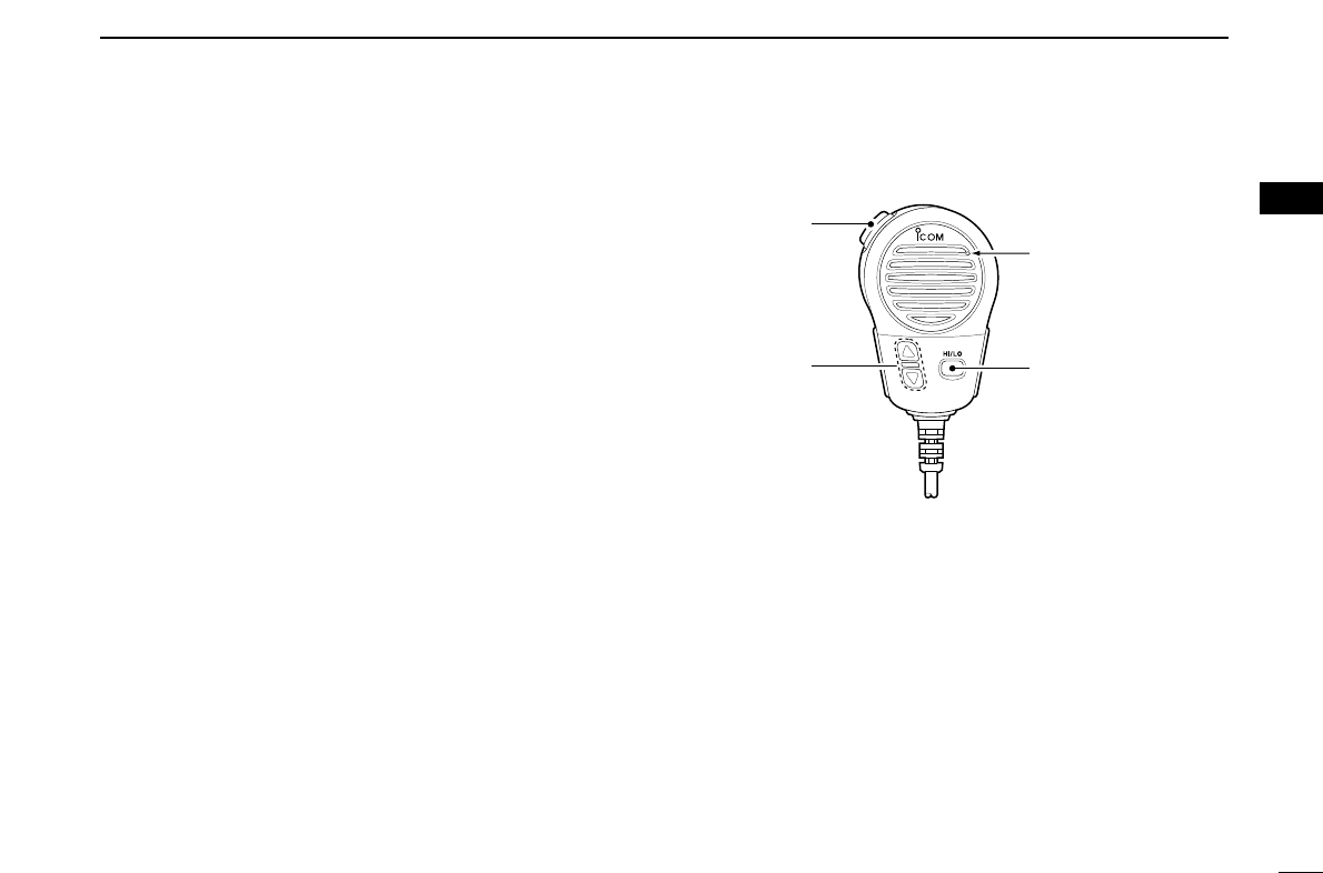
■Microphone
qPTT SWITCH [PTT]
Push and hold to transmit; release to receive. (p. 7)
wCHANNEL UP/DOWN KEYS [YY]/[ZZ]
➥Push either key to change the operating channel, Set
mode settings, etc. (pgs. 5, 6, 28)
➥When the Favorite channel function is turned ON, push
either key to select the favorite channels in the selected
channel group in sequence. (p. 30)
eTRANSMIT POWER KEY [HI/LO]
➥Push to toggle the power high and low. (p. 7)
• Some channels are set to low power only.
➥While pushing and holding [HI/LO], turn power ON to
toggle the Microphone Lock function ON and OFF.
(p. 9)
Microphone
w
q
e
2
4
2PANEL DESCRIPTION
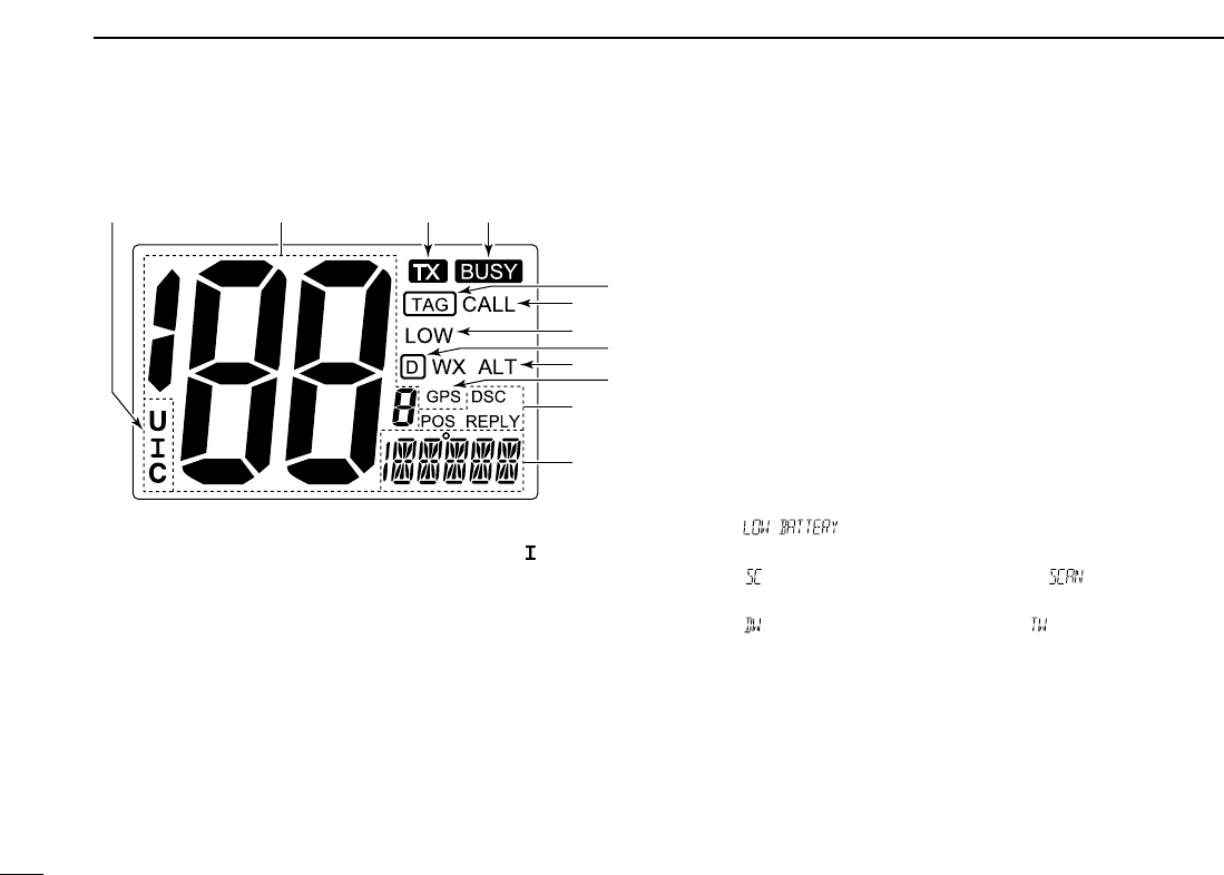
■Function display
qCHANNEL GROUP INDICATOR (p. 6)
Indicates whether a U.S.A. “U,” International “”or Cana-
dian “C” channel is in use.
wCHANNEL NUMBER READOUT
➥Indicates the selected operating channel number.
• Refer to CHANNEL LIST. (p. 36)
➥In Set mode, indicates the selected condition. (p. 28)
eTRANSMIT INDICATOR (p. 7)
Appears while transmitting.
rBUSY INDICATOR (p. 7)
Appears when receiving a signal or when the squelch
opens.
tCALL CHANNEL INDICATOR (p. 5)
Appears when the call channel is selected.
yLOW POWER INDICATOR (p. 7)
Appears when low power is selected.
uWEATHER CHANNEL INDICATOR (pgs. 6, 29)
➥“WX” appears when a weather channel is selected.
➥“WX ALT” appears when the Weather alert function is in
use; blinks when an alert tone is received.
iDSC INDICATOR
➥“DSC” appears when a DSC call is received. (p. 24)
➥“POS REPLY” appears when a Position Reply call or
Position Report Reply call is received. (p. 27)
oCHANNEL COMMENT INDICATOR
➥Channel comment appears if programmed. (p. 8)
➥“ ” scrolls when the battery voltage drops to
approx. 10.8 V DC or below.
➥“ ” blinks during Priority scan; “ ” blinks during
Normal scan. (p. 11)
➥“ ” blinks during Dualwatch; “ ” blinks during Tri-
watch. (p. 12)
!0 TAG CHANNEL INDICATOR (p. 11)
Appears when a TAG channel is selected.
!1 DUPLEX INDICATOR (p. 6)
Appears when a duplex channel is selected.
!2 GPS INDICATOR
➥Appears while valid position data is received.
➥Blinks when invalid position data is received.
➥Disappears when no GPS receiver is connected.
!0
wqer
!2
!1
t
y
u
o
i
5
3
BASIC OPERATION
2
3
■Channel selection
ïï
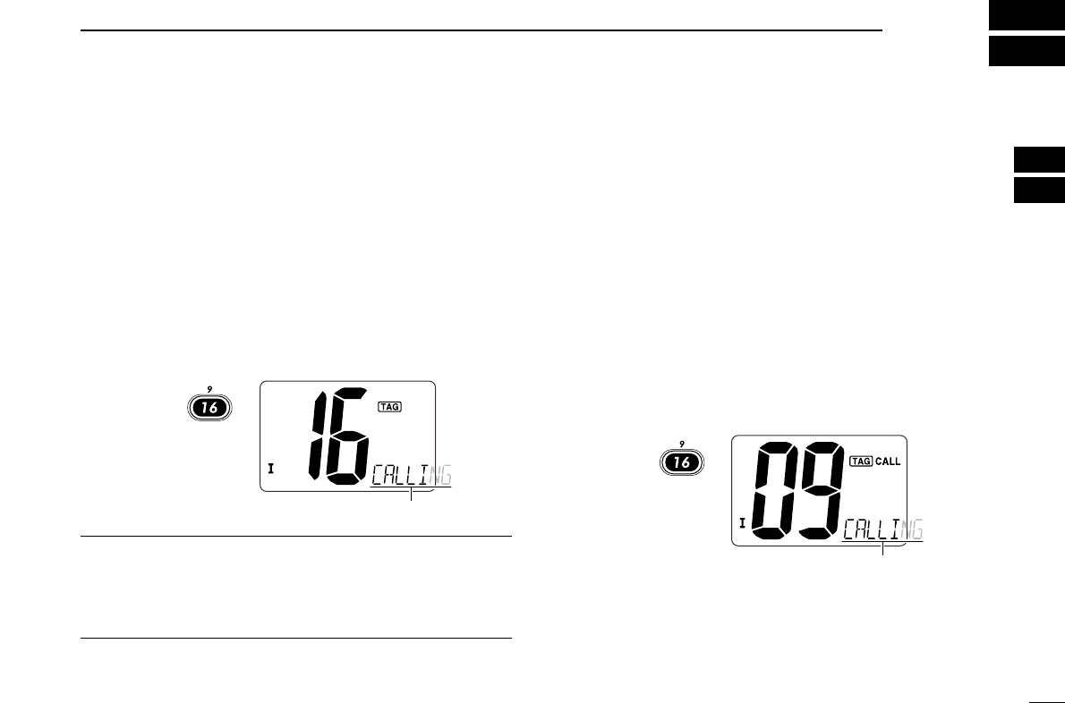
Channel 16
Channel 16 is the distress and safety channel. It is used for
establishing initial contact with a station and for emergency
communications. Channel 16 is monitored during both Dual-
watch and Tri-watch. While standing by, you must monitor
Channel 16.
➥Push [!6•9] momentarily to select Channel 16.
➥Push [CH/WX•DUAL] to return to the condition before se-
lecting Channel 16, or push [Y]or [Z]to select operating
channel.
Convenient!
When the Favorite channel function is turned ON (p. 30),
[Y]/[Z]keys on the microphone select the favorite channels
in the selected channel group in sequence when pushed.
• The favorite channels are set by the TAG channel setting. (p. 11)
ïï
Channel 9 (Call channel)
Each regular channel group has a separate leisure-use call
channel. The call channel is monitored during Tri-watch. The
call channels can be programmed (p. 8) and are used to store
your most often used channels in each channel group for
quick recall.
➥Push and hold [!6•9] for 1 sec. to select the call channel of
the selected channel group.
•“CALL” and call channel number appear.
• Each channel group may have an independent call channel after
programming a call channel. (p. 8)
➥Push [CH/WX•DUAL] to return to the condition before se-
lecting call channel, or push [Y]or [Z]to select a channel.
Push
for 1 sec.
Scrolls
Push
Scrolls
6
3BASIC OPERATION
ïï
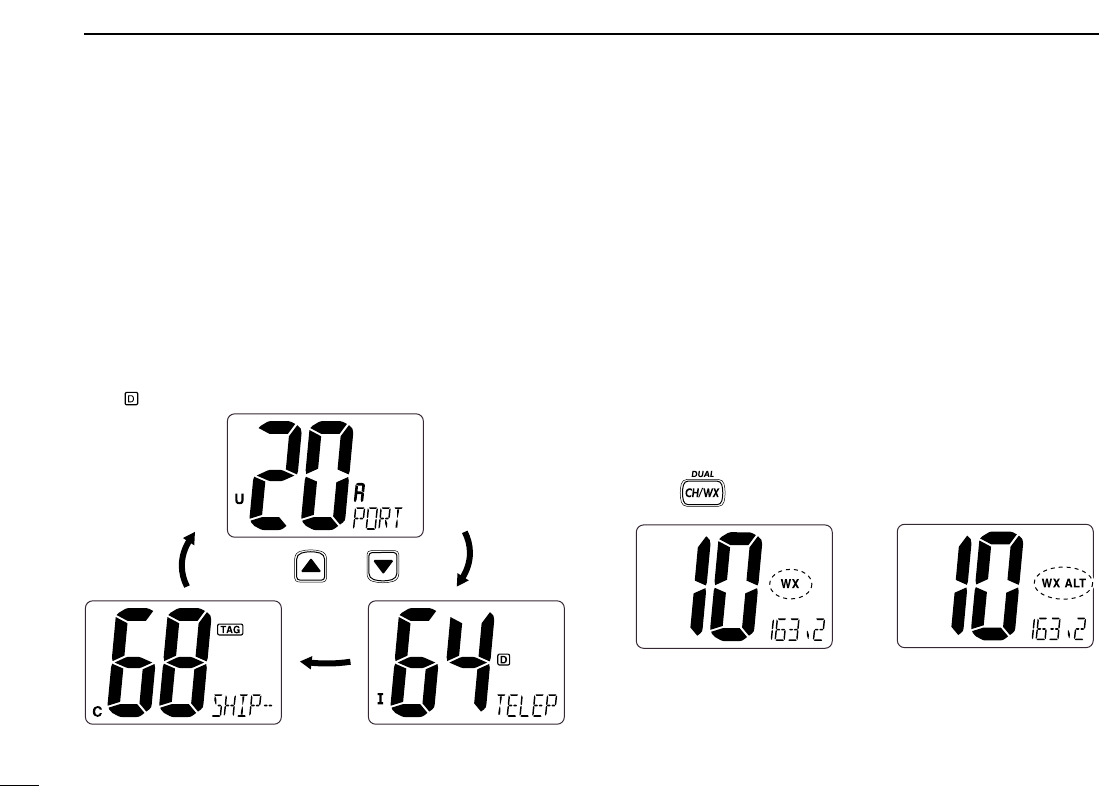
U.S.A.,Canadian and international channels
The IC-M304 is pre-programmed with 59 U.S.A., 59 interna-
tional and 63 Canadian channels. These channel groups may
be specified for the operating area.
qPush [CH/WX•DUAL] to select a regular channel.
• If a weather channel appears, push [CH/WX•DUAL] again.
wPush both [Y]and [Z]on the transceiver to change the
channel group, if necessary.
• U.S.A., International and Canadian channel groups can be se-
lected in sequence.
ePush [Y]or [Z]to select a channel.
• “ ” appears for duplex channels.
ïï
Weather channels
The IC-M304 has 10 pre-programmed weather channels.
These are used for monitoring broadcasts from NOAA (Na-
tional Oceanographic and Atmospheric Administration.)
The transceiver can automatically detect a weather alert tone
on the selected weather channel while receiving the channel
or during scanning. (p. 29)
qPush [CH/WX•DUAL] once or twice to select a weather
channel.
•“WX” appears when a weather channel is selected.
• “WX ALT” appears when the Weather alert function is in use.
(p. 29)
wPush [Y]or [Z]to select a channel.
Push once or twice
When Weather alert is OFF. When Weather alert is ON.
Push and
7
3
BASIC OPERATION
3
■Receiving and transmitting
CAUTION: Transmitting without an antenna will damage
the transceiver.
qRotate [VOL] to turn power ON.
wSet the audio and squelch levels.
➥Rotate [SQL] fully counterclockwise in advance.
➥Rotate [VOL] to adjust the audio output level.
➥Rotate [SQL] clockwise until the noise disappears.
ePush both [Y]and [Z]on the transceiver several times to
select the desired channel group. (p. 6)
rPush [Y]or [Z]to select a channel. (p. 5)
• When receiving a signal, “ ” appears and audio is emitted
from the speaker.
• Further adjustment of [VOL] may be necessary.
tPush [HI/LO] to select the output power if necessary.
•“LOW” appears when low power is selected.
• Choose low power for short range communications, choose high
power for longer distance communications.
• Some channels are for low power only.
yPush and hold [PTT] to transmit, then speak into the mi-
crophone.
• “ ” appears.
• Channel 70 cannot be used for transmission other than DSC.
uRelease [PTT] to receive.
Simplex channels, 3, 21, 23, 61, 64, 81, 82 and 83 CAN-
NOT be lawfully used by the general public in U.S.A. wa-
ters.
IMPORTANT: To maximize the readability of your trans-
mitted signal, pause a few sec. after pushing [PTT], hold
the microphone 2 to 4 inches (5 to 10 cm) from your mouth
and speak into the microphone at a normal voice level.
✔NOTE for TOT (Time-out Timer) function
The TOT function inhibits continuous transmission over a pre-
set time period after the transmission starts.
u
rt
yq Microphone
w
re
8
3BASIC OPERATION
■Call channel programming
Call channel is used to select Channel 9 (default), however,
you can program the call channel with your most often-used
channels in each channel group for quick recall.
qPush both [Y]and [Z]on the transceiver several times to
select the desired channel group (U.S.A., International or
Canada) to be programmed.
wPush and hold [!6•9] for 1 sec. to select the call channel of
the selected channel group.
•“CALL” and call channel number appear.
ePush and hold [!6•9] again
for 3 sec. (until a long beep
changes to 2 short beeps)
to enter call channel pro-
gramming condition.
• Channel number starts blink-
ing.
rPush [Y]or [Z]to select
the desired channel.
tPush [!6•9] to program the
displayed channel as the
call channel.
• Push [CH/WX•DUAL] to can-
cel.
• The channel number stops
blinking.
■Channel comments
Memory channels can be labeled with a unique alphanumeric
ID of up to 10 characters each.
More than 6 characters comment scrolls automatically at the
channel comment indicator after the channel selection.
Capital letters, small letters (except f, j, k, p, s, v, x, z), 0 to 9,
some symbols (= ✱+ – . /) and space can be used.
qSelect the desired channel.
• Cancel Dualwatch, Tri-watch or Scan in advance.
wWhile pushing [CH/WX•DUAL], push [!6•9] to edit the
channel comment.
• A cursor and the first char-
acter start blinking alter-
nately.
ePushing [Y]or [Z]to select the desired character.
• Push [!6•9] or [CH/WX•DUAL] to move the cursor forward or
backward, respectively.
rRepeat step eto input all characters.
tPush [DSC•POS] to input and set the comment.
• Push [SCAN•TAG] to cancel.
• The cursor and the character stop blinking.
yRepeat steps qto tto program other channel com-
ments, if desired.
9
3
BASIC OPERATION
3
■Microphone lock function
The microphone lock function electrically locks [Y]and [Z]
keys on the supplied microphone. This prevents accidental
channel changes and function access.
➥While pushing and holding [HI/LO] on the microphone,
turn power ON to toggle the Microphone lock function ON
and OFF.
■Display backlighting
The function display and keys can be backlit for better visibil-
ity under low light conditions.
➥While pushing and holding [SCAN•TAG], push [YY]or [ZZ]
to adjust the brightness of the LCD and key backlight.
• The backlight is selectable in 3 levels and OFF.
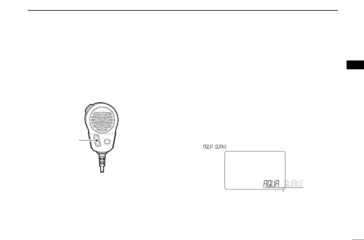
■AquaQuake water draining
function
The IC-M304 uses a new technology to clear water away
from the speaker grill: AquaQuake. AquaQuake helps drain
water away from the speaker housing (water that might oth-
erwise muffle the sound coming from the speaker). The IC-
M304 emits a vibrating noise when this function is being
used.
➥While pushing and holding [Y]and [Z], turn power ON.
• A low beep tone sounds while [Y]or [Z]keys are held to drain
water, regardless of [VOL] control setting.
• The transceiver never accepts a key operation while the
AquaQuake function is activated.
• “ ” scrolls at the channel comment indicator.
Scrolls
[Y]/[Z]
10
SCAN OPERATION
4
■Scan types
Scanning is an efficient way to locate signals quickly over a
wide frequency range. The transceiver has Priority scan and
Normal scan.
When the Weather alert function is turned ON, the previously
selected (last used) weather channel is also checked while
scanning. (p. 29)
Set the TAG channels (scanned channel) before scanning.
Clear the TAG channels which inconveniently stop scanning,
such as those for digital communication use. (Refer to the
right page for details.)
Choose Priority or Normal scan in Set mode. (p. 29)
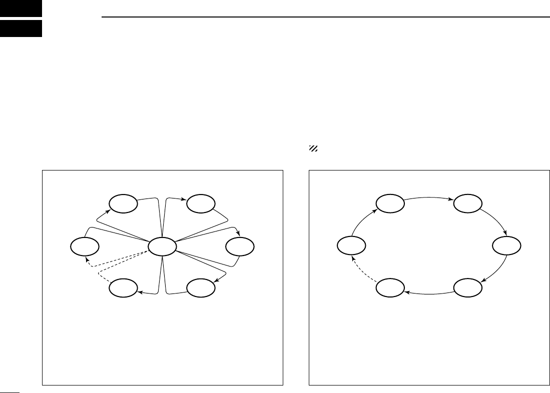
PRIORITY SCAN
Priority scan searches through all TAG channels in se-
quence while monitoring Channel 16. When a signal is de-
tected on Channel 16, scan pauses until the signal disap-
pears; when a signal is detected on a channel other than
Channel 16, scan becomes Dualwatch until the signal dis-
appears.
CH 06
CH 01
CH 16
CH 02
CH 05 CH 04
CH 03
NORMAL SCAN
Normal scan, like priority scan, searches through all TAG
channels in sequence. However, unlike priority scan, Chan-
nel 16 is not checked unless Channel 16 is set as a TAG
channel.
CH 01 CH 02
CH 06
CH 05 CH 04
CH 03
11
4
SCAN OPERATION
4
■Setting TAG channels
For more efficient scanning, add desired channels as TAG
channels or clear the TAG for unwanted channels.
Channels that are not tagged will be skipped during scanning.
TAG channels can be assigned to each channel group
(U.S.A., International and Canada) independently.
qPush both [YY]and [ZZ]several times to select the desired
channel group.
wSelect the desired channel to be set as a TAG channel.
ePush and hold [SCAN•TAG] for 1 sec. to set the displayed
channel as a TAG channel.
• “ ” appears in the display.
rTo cancel the TAG channel setting, repeat step e.
• “ ” disappears.
✔Clearing (or setting) all tagged channels
While pushing and holding [HI/LO] on the microphone, push
[SCAN•TAG] for 3 sec. (until a long beep changes to 2 short
beeps) to clear all TAG channels in the channel group.
• Repeat above procedure to set all TAG channels.
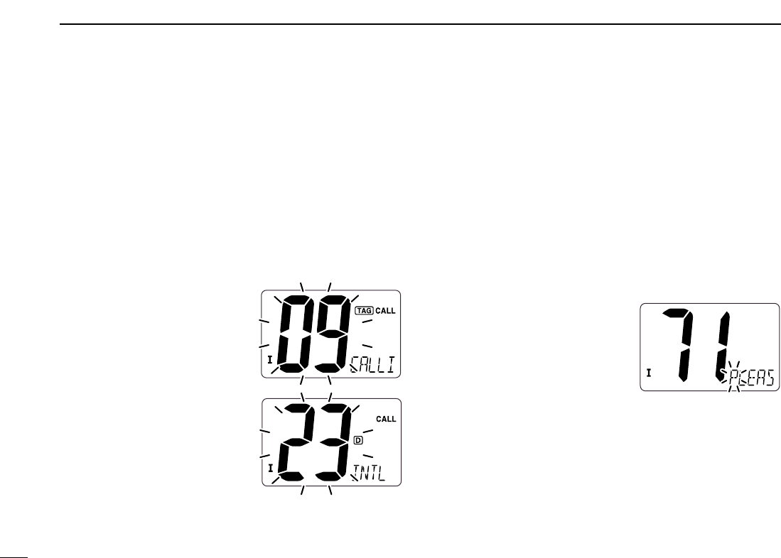
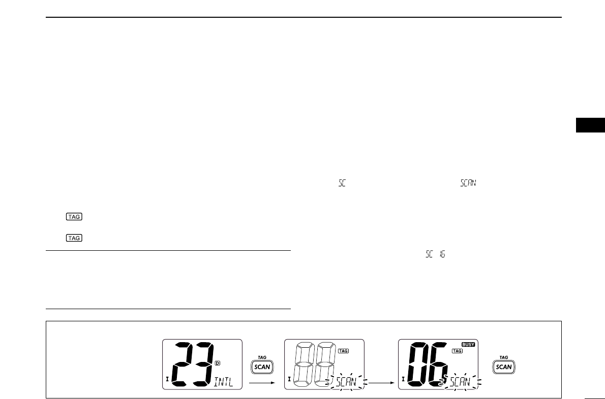
■Starting a scan
Set scan type (Priority or Normal scan) and scan resume
timer in advance using Set mode. (p. 29)
qPush both [YY]and [ZZ]several times to select the desired
channel group, if desired.
wSet TAG channels as described at left.
eMake sure the squelch is closed to start a scan.
rPush [SCAN•TAG] to start Priority or Normal scan.
• “ ” blinks during Priority scan; “ ” blinks during Normal
scan.
• When a signal is detected, scan pauses until the signal disap-
pears or resumes after pausing 5 sec. according to Set mode
setting. (Channel 16 is still monitored during Priority scan.)
• Push [Y]or [Z]to check the scanning TAG channels, to change
the scanning direction or resume the scan manually.
• A beep tone sounds and “ ” blinks at the channel comment
indicator when a signal is received on Channel 16 during Priority
scan.
tTo stop the scan, push [SCAN•TAG].
to stop the scan
PushPush
Scan starts. When a signal is received.
[Example]: Starting a normal scan.
12
DUALWATCH/TRI-WATCH
5
■Description
Dualwatch monitors Channel 16 while you are receiving
on another channel; Tri-watch monitors Channel 16 and the
call channel while receiving another channel. Dualwatch/Tri-
watch are convenient for monitor Channel 16 when you are
operating on another channel.
■Operation
qSelect Dualwatch or Tri-watch in Set mode. (p. 29)
wSelect the desired channel.
ePush and hold [CH/WX•DUAL] for 1 sec. to start Dual-
watch or Tri-watch.
• “ ” blinks during Dualwatch; “ ” blinks during Tri-watch.
• A beep tone sounds when a signal is received on Channel 16.
rTo cancel Dualwatch or Tri-watch, push [CH/WX•DUAL].
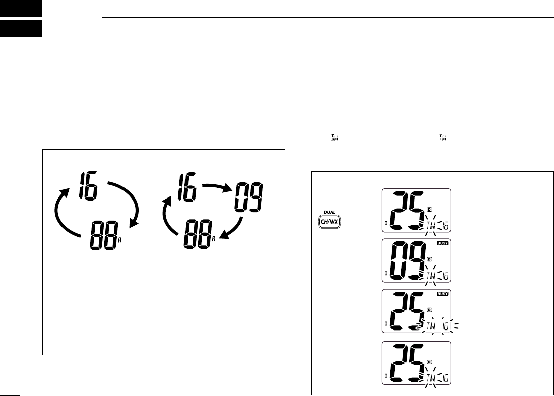
DUALWATCH/TRI-WATCH SIMULATION
• If a signal is received on Channel 16, Dualwatch/Tri-watch
pauses on Channel 16 until the signal disappears.
• If a signal is received on the call channel during Tri-watch,
Tri-watch becomes Dualwatch until the signal disappears.
• To transmit on the selected channel during Dualwatch/Tri-
watch, push and hold [PTT].
Dualwatch Tri-watch
Call channel
[Example]: Operating Tri-watch on INT Channel 25
Tri-watch starts.
Signal is received on call
channel.
Signal is received on
Channel 16 takes priority.
Tri-watch resumes after
the signal disappears.
Push and hold
for 1 sec.

13
6
DSC OPERATION
5
6
■MMSI code programming
The 9-digit MMSI (Maritime Mobile Service Identity: DSC self
ID) code can be programmed at power ON.
This code programming can be performed only twice.
qTurn power OFF.
wWhile pushing and holding [DSC•POS], turn power ON to
enter MMSI code programming condition.
eAfter the display appears, release [DSC•POS].
• A cursor starts blinking.
rEdit the specified MMSI code by pushing [Y]or [Z].
• Push [!6•9] or [CH/WX•DUAL] to move the cursor forward or
backward, respectively.
tInput 9-digit code, then push [DSC•POS] to set the code.
• Returns to the normal operation.
■MMSI code check
The 9-digit MMSI (DSC self ID) code can be checked.
qPush [DSC•POS] to enter the DSC menu.
wPush [Y]or [Z]to select “ ” and push [DSC•POS].
eCheck the 9-digit MMSI (DSC self ID) code.
• The MMSI code is displayed and scrolls at the channel comment
indicator.
rPush [DSC•POS] to exit the DSC menu.
MMSI (DSC self ID) code scrolls
14
6DSC OPERATION
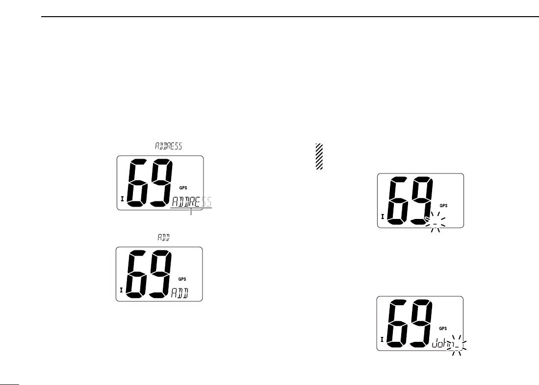
■DSC address ID
A total of 30 DSC address IDs (9-digit) can be programmed
and named with up to 5 characters.
DProgramming address ID
qPush [DSC•POS] to enter the DSC menu.
wPush [Y]or [Z]to select “ ,” and push [DSC•POS].
ePush [Y]or [Z]to select “ ,” and push [DSC•POS].
rPush [Y]or [Z]to input 9-digit of the appropriate address
ID.
• Push [!6•9] or [CH/WX•DUAL] to move the cursor forward or
backward, respectively.
• Push [SCAN•TAG] to cancel and exit the condition.
1st digit ‘0’ is fixed for a group ID. When you input 1st digit ‘0’
and other 8 digits, the ID is automatically registered as a group
ID.
tAfter inputting 9-digit ID, push [DSC•POS] to input 5 char-
acters ID name using [Y]or [Z].
• Push [!6•9] or [CH/WX•DUAL] to move the cursor forward or
backward, respectively.
• Push [SCAN•TAG] to cancel and exit the condition.
yPush [DSC•POS] to program and exit the DSC menu.
Scrolls
15
6
DSC OPERATION
6
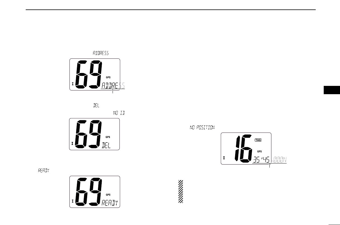
DDeleting address ID
qPush [DSC•POS] to enter the DSC menu.
wPush [Y]or [Z]to select “ ” and push [DSC•POS].
ePush [Y]or [Z]to select “ ”, then push [DSC•POS].
• When no address ID is programmed, “ ” is displayed.
rPush [Y]or [Z]to select the desired ID name for deleting
and push [DSC•POS].
• “ ” appears.
tPush [DSC•POS] to delete the address ID and exit the
DSC menu.
■Position indication
When a GPS receiver (NMEA0183 ver. 2.0 or 3.01) is con-
nected, the transceiver indicates the current position data in
seconds of accuracy.
A NMEA0183 ver. 2.0 or 3.01 (sentence formatters RMC,
GGA, GNS, GLL) compatible GPS receiver is required. Ask
your dealer about suitable GPS receivers.
➥Push and hold [DSC•POS] for 1 sec. to display the current
position.
• ‘Latitude’ and ‘Longitude’ scroll in sequence at the channel com-
ment indicator.
• “ ” scrolls when no GPS is connected.
• When the connecting GPS receiver is compatible with
several sentence formatters, the order of input prece-
dence is ‘RMC,’ ‘GGA,’ ‘GNS’ and ‘GLL.’
• “GPS” blinks when the GPS data is invalid.
Scrolls
Scrolls
16
6DSC OPERATION
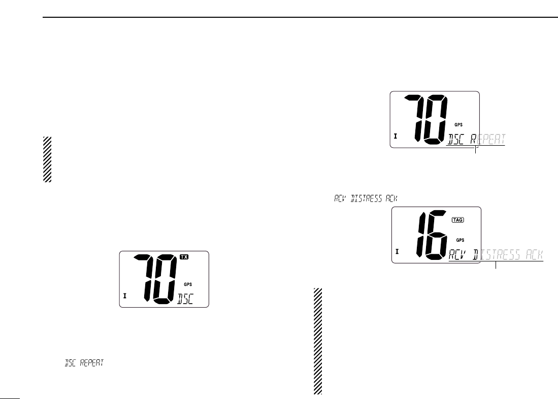
■Distress call
A Distress call should be transmitted if, in the opinion of the
Master, the ship or a person is in distress and requires imme-
diate assistance.
NEVER USE THE DISTRESS CALL WHEN YOUR
SHIP OR A PERSON IS NOT IN AN EMERGENCY.
A DISTRESS CALL CAN BE USED ONLY WHEN
IMMEDIATE HELP IS NEEDED.
qConfirm no Distress call is being received.
wWhile opening the key cover, push [DISTRESS] for 5 sec.
to transmit the Distress call.
• Emergency channel (Channel 70) is automatically selected and
the Distress call is transmitted.
eAfter transmitting the call, the transceiver waits for an ac-
knowledgment call on Channel 70.
• The Distress call is automatically transmitted every 3.5 to 4.5
minutes.
• “ ” scrolls at the channel comment indicator.
rAfter receiving the acknowledgment, reply using the mi-
crophone.
• “ ” scrolls at the channel comment indicator.
➥A distress alert contains;
• Kinds of distress : Undesignated distress
• Position data : GPS position data held for 23.5 hrs. or until
the power is turned OFF.
➥The Distress call is repeated every 3.5–4.5 min., until
receiving an ‘acknowledgement.’
➥Push and hold [DISTRESS] for 5 sec. to transmit a re-
newed Distress call, if desired.
➥Push any key except [DISTRESS] to cancel the ‘Call
repeat’ mode.
Scrolls
Scrolls
17
6
DSC OPERATION
6
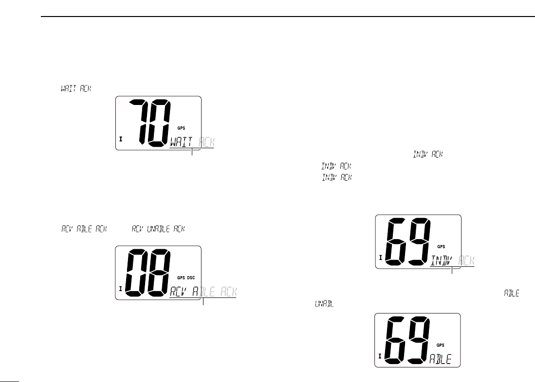
■Transmitting DSC calls
To ensure correct operation of the DSC function, please
make sure you set the squelch correctly. (p. 7)
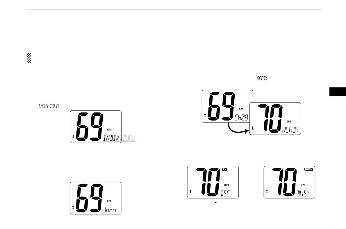
DTransmitting Individual call
The Individual call function allows you to transmit a DSC sig-
nal to a specific ship only.
qPush [DSC•POS] to enter the DSC menu.
• “ ” scrolls at the channel comment indicator.
wPush [DSC•POS] to select the desired pre-programmed in-
dividual address using [Y]or [Z], then push [DSC•POS].
• The ID code for the individual call must be set in advance.
(p. 14)
ePush [Y]or [Z] to select a desired intership channel, push
[DSC•POS].
• Intership channels are already preset into the transceiver in rec-
ommended order.
• Channel 70 is selected and “ ” appears after pushing
[DSC•POS].
rPush [DSC•POS] to transmit the Individual call.
• If Channel 70 is busy, the transceiver stands by until the channel
becomes clear.
• Routine category only is available.
When Ch 70 is busy.Push [DSC POS] to
transmit DSC call.
Scrolls
18
6DSC OPERATION
tAfter transmitting the Individual call, standby on Channel
70 until an acknowledgement is received.
• “ ” scrolls at the channel comment indicator.
yWhen the acknowledgement ‘Able to comply’ is received,
the specified channel (in step e) is selected with beeps
automatically. Or, when the acknowledgement ‘Unable to
comply’ is received, the display returns to the operated
channel (before entering the DSC menu) with beeps.
• “ ” or “ ” scrolls at the channel
comment indicator.
uPush and hold [PTT] to communicate your message to the
responding ship.
DTransmitting Individual acknowledgement
When receiving an Individual call, you can transmit an ac-
knowledgement (‘Able to comply’ or ‘Unable to comply’) by
using the on screen prompts (see page 25 for details). You
can also send an acknowledgement through the menu sys-
tem as follows.
qPush [DSC•POS] to enter the DSC menu.
wPush [Y]or [Z] to select “ ” and push [DSC•POS].
• “ ” item appears after an Individual call is received.
• “ ” item disappears if another call is received after the
Individual call.
• The Individual acknowledgement can be transmitted to the last
received individual call only.
ePush [Y]or [Z]to select the acknowledgement “ ” or
“.”
Scrolls
Scrolls
‘Able to comply’
is received
Scrolls
19
6
DSC OPERATION
6
rPush [DSC•POS] to enter selected Individual call ac-
knowledgement.
• “ ” appears at the channel comment indicator.
tPush [DSC•POS] to transmit the acknowledgement to the
selected station.
yAfter the Individual acknowledgement has been transmit-
ted, the display changes to the channel specified by the
calling station automatically when “ ” is selected.
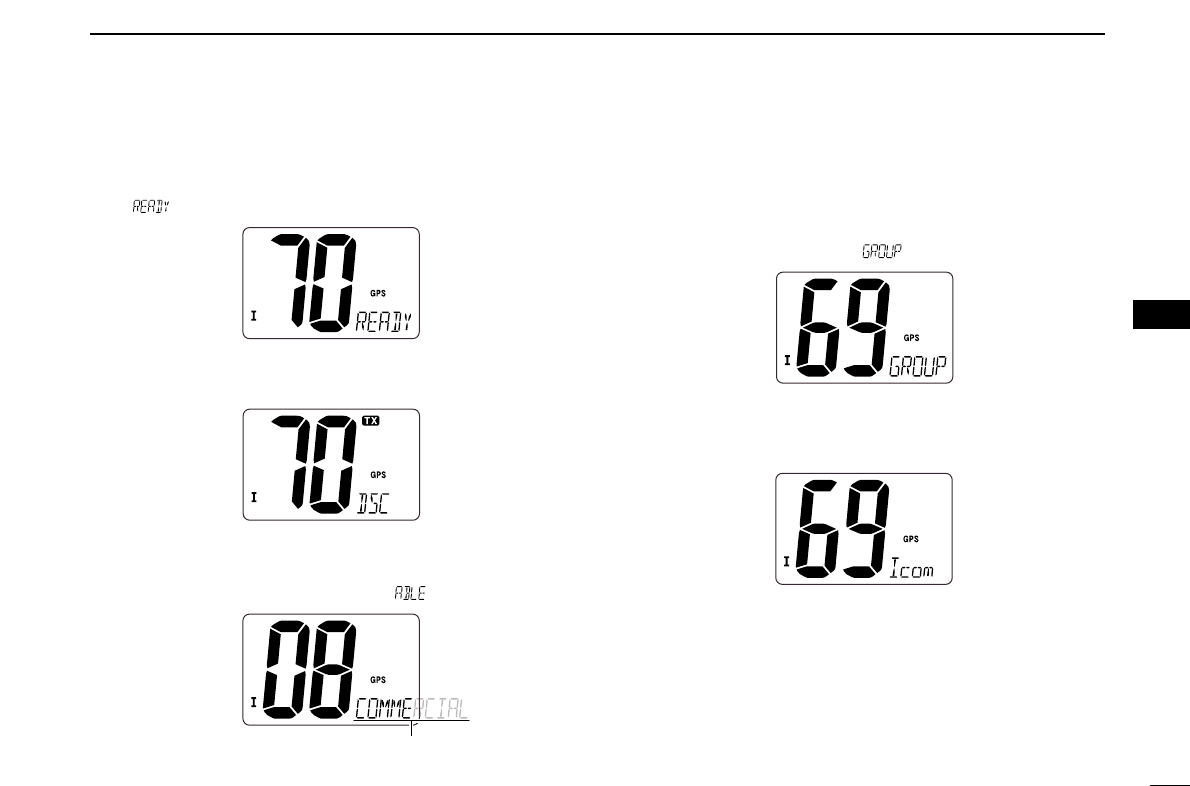
DTransmitting Group call
The Group call function allows you to transmit a DSC signal
to a specific group only.
qPush [DSC•POS] to enter the DSC menu.
wPush [Y]or [Z] to select “ ,” and push [DSC•POS].
ePush [Y]or [Z] to select the desired pre-programmed
group address, and push [DSC•POS].
• The ID code for the group call must be set in advance. (p. 14)
Scrolls
rPush [Y]or [Z] to select the desired intership channel,
and push [DSC•POS].
• Channel 70 is selected and “ ” appears.
tPush [DSC•POS] to transmit the Group call.
• If Channel 70 is busy, the transceiver stands by until the channel
becomes clear.
• Routine category only is available.
yAfter the Group call has been transmitted, the display
changes to the previously specified channel.
uPush and hold [PTT] to communicate your message to the
responding ship.
Scrolls
20
6DSC OPERATION
21
6
DSC OPERATION
6
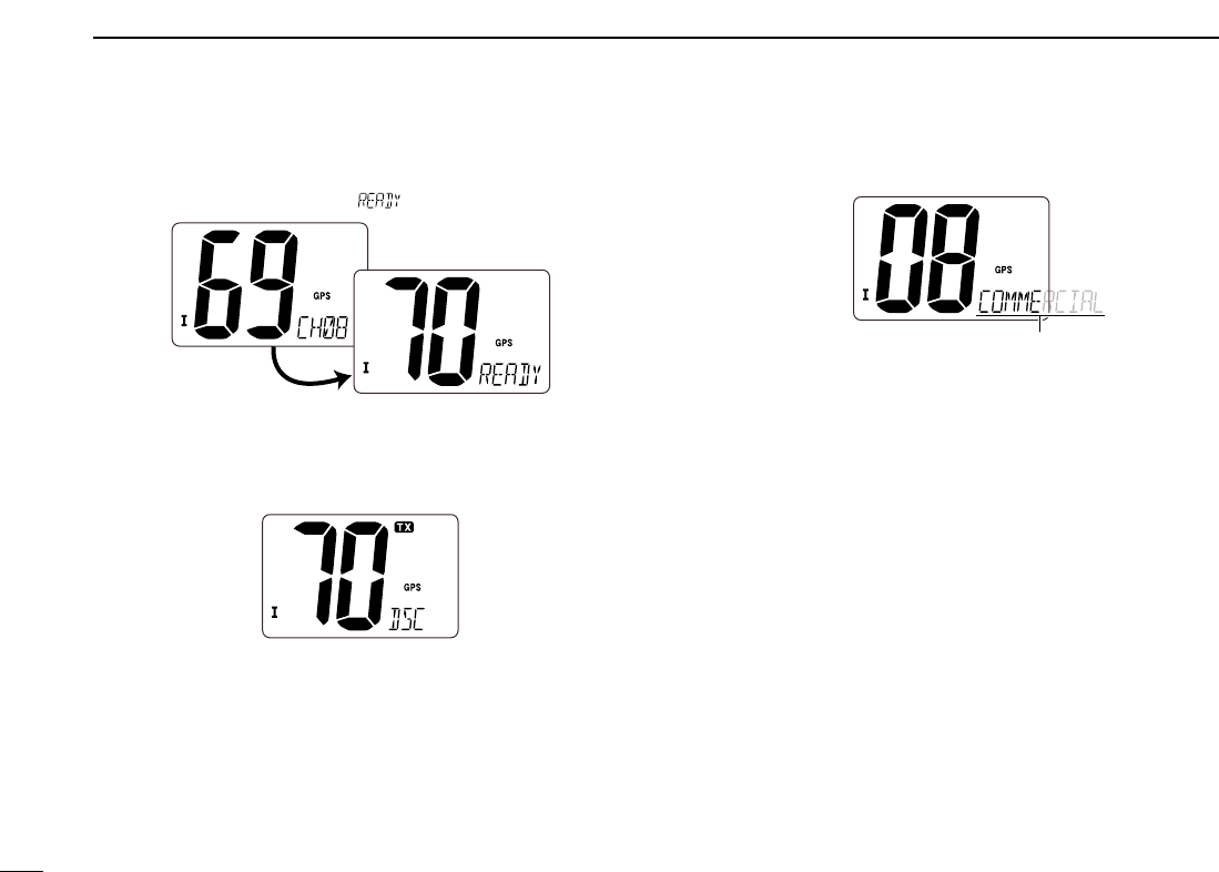
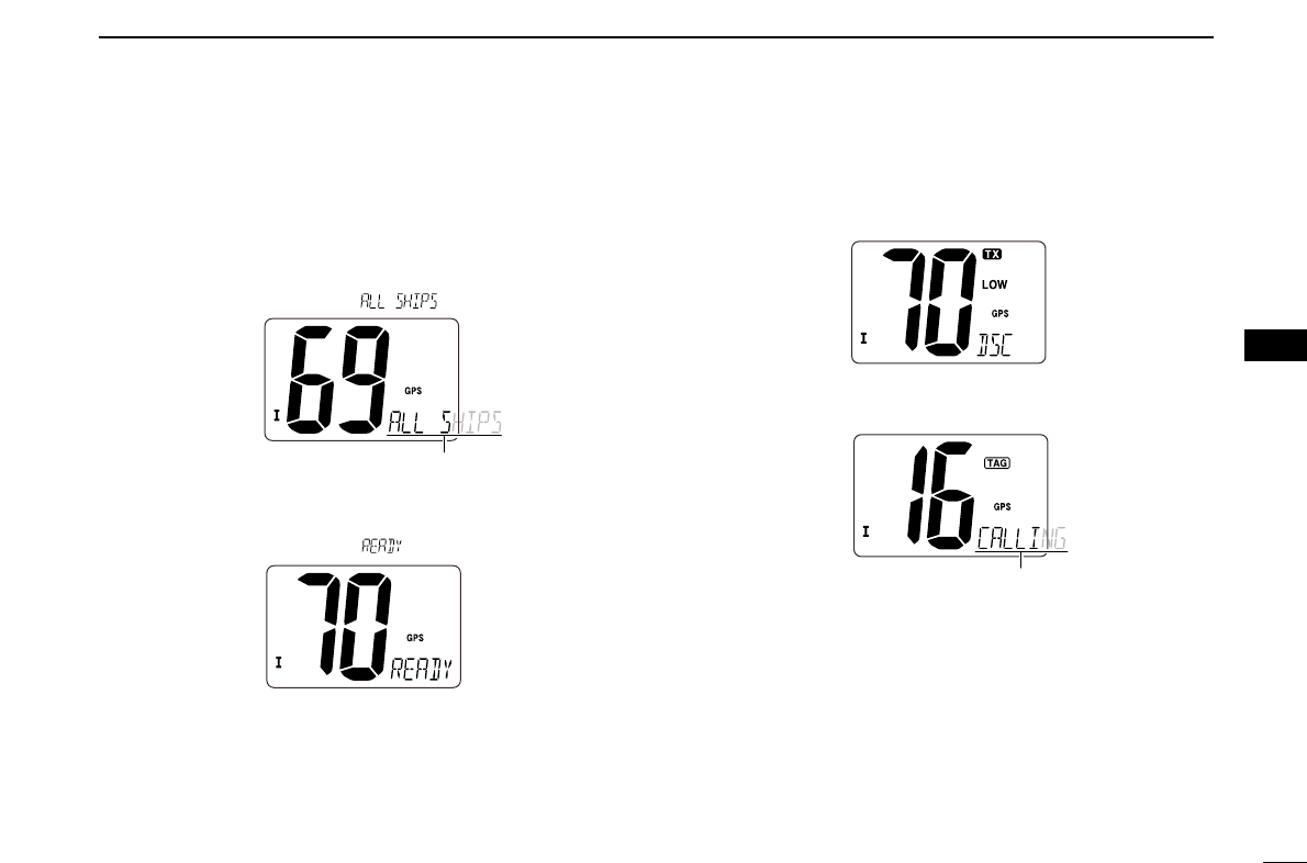
DTransmitting All Ships call
Large ships use Channel 70 as their ‘listening channel.’
When you want to announce a message to these ships, use
the
‘
All Ships call’ function.
qPush [DSC•POS] to enter the DSC menu.
wPush [Y]or [Z]to select “ .”
ePush [DSC•POS] to enter the standby condition for All
Ships call.
• Channel 70 is selected and “ ” appears.
rPush [DSC•POS] to transmit the All Ships call.
• Routine category only is available.
• Low power is selected.
tAfter the All Ships call has been transmitted, the display
changes to Channel 16 automatically.
Scrolls
Scrolls
22
6DSC OPERATION
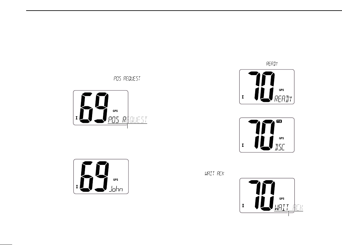
DTransmitting Position Request call
Transmit a Position Request call when you want to know a
specified ship’s current position, etc.
qPush [DSC•POS] to enter the DSC menu.
wPush [Y]or [Z] to select “ ,” then push
[DSC•POS].
ePush [Y]or [Z] to select the desired pre-programmed in-
dividual address.
• The ID code for position request must be set in advance. (p. 14)
rPush [DSC•POS] to enter the standby condition for Posi-
tion Request call.
• Channel 70 is selected and “ ” appears.
tPush [DSC•POS] to transmit the Position Request call.
yAfter the Position Request call has been transmitted, the
following indication is displayed.
• “ ” scrolls at the channel comment indicator.
uPush any key to exit the condition and return to the normal
operation.
Scrolls
Scrolls
23
6
DSC OPERATION
6
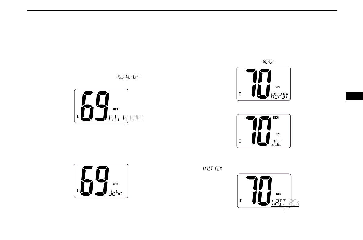
DTransmitting Position Report call
Transmit a Position Report call when you want to announce
your own position to a specific ship and to get an answer, etc.
qPush [DSC•POS] to enter the DSC menu.
wPush [Y]or [Z]to select “ ,” and push
[DSC•POS].
ePush [Y]or [Z] to select the desired pre-programmed in-
dividual address.
• The ID code for the position report call can be set in advance.
(p. 14)
rPush [DSC•POS] to enter the standby condition for Posi-
tion Report call.
• Channel 70 is selected and “ ” appears.
tPush [DSC•POS] to transmit the Position Report call.
yAfter the Position Report call has been transmitted, stand
by on Channel 70 until an acknowledgement is received.
• “ ” scrolls at the channel comment indicator.
uPush any key to exit the condition and return to the normal
operation.
Scrolls
Scrolls
24
6DSC OPERATION
■Receiving DSC calls
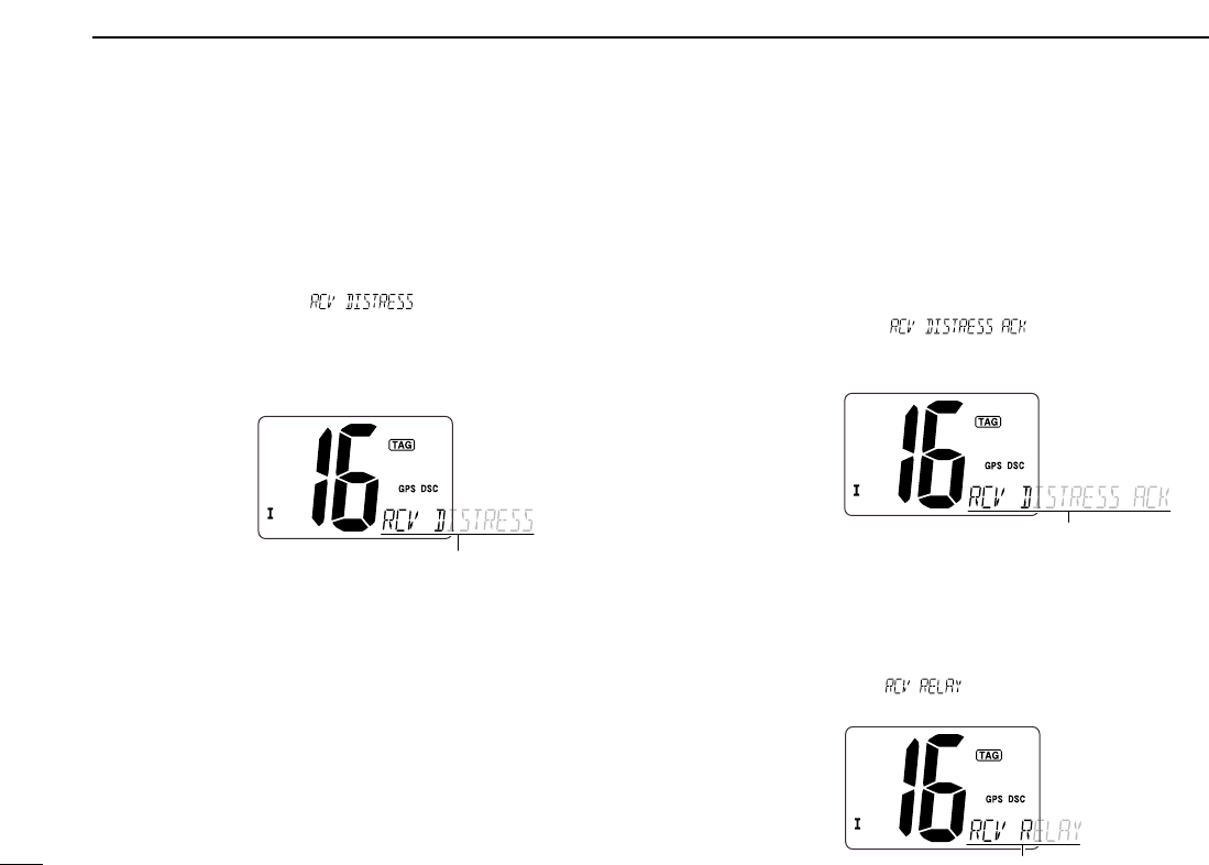
DReceiving a Distress call
While monitoring Channel 70 and a Distress call is received:
➥The emergency alarm sounds.
• Push any key to stop the alarm.
➥“DSC” appears and “ ” scrolls at the channel
comment indicator, then Channel 16 is automatically se-
lected.
➥Continue monitoring Channel 16 as a coast station may re-
quire assistance.
DReceiving a Distress acknowledgement
While monitoring Channel 70 and a Distress acknowledge-
ment to other ship is received:
➥The emergency alarm sounds.
• Push any key to stop the alarm.
➥“DSC” appears and “ ” scrolls at the chan-
nel comment indicator, then Channel 16 is automatically
selected.
DReceiving a Distress Relay call
While monitoring Channel 70 and a Distress Relay acknowl-
edgement is received:
➥The emergency alarm sounds.
• Push any key to stop the alarm.
➥“DSC” appears and “ ” scrolls at the channel com-
ment indicator, then Channel 16 is automatically selected.
Scrolls
Scrolls
Scrolls

25
6
DSC OPERATION
6
DReceiving an Individual call
While monitoring Channel 70 and an Individual call is re-
ceived:
➥The emergency alarm or beeps sound depending on the
received category.
➥“DSC” appears and “ ” scrolls at the channel
comment indicator.
➥Push any key to stop beep, then push [DSC•POS] to reply
the call and select the channel specified by the calling sta-
tion for voice communication (depending on your replying
condition see p. 18 for individual acknowledgement call
procedure for details.); push any other key to ignore the In-
dividual call.
DReceiving a Group call
While monitoring Channel 70 and a Group call is received:
➥The emergency alarm or beeps sound depending on the
received category.
➥“DSC” appears and “ ” scrolls at the channel
comment indicator.
➥Push any key to stop beep, then push [DSC•POS] to se-
lect the channel specified by the calling station for voice
communication; push any other key to ignore the Group
call.
Scrolls
Scrolls
26
6DSC OPERATION
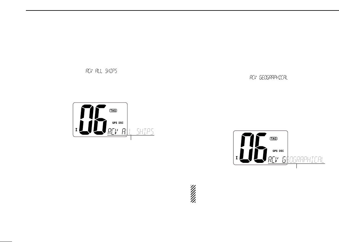
DReceiving an All Ships call
While monitoring Channel 70 and an All Ships call is received:
➥The emergency alarm sounds when the category is ‘Dis-
tress’ or ‘Urgency’; 2 beeps sound for other categories.
➥“DSC” appears and “ ” scrolls at the channel
comment indicator.
➥Push any key to stop beep, then push [DSC•POS] to mon-
itor channel 16 for an announcement from the calling ves-
sel, push any other key to ignore the call.
DReceiving a Geographical Area call
While monitoring Channel 70 and a Geographical Area call
(for the area you are in) is received:
➥The emergency alarm or beeps sound depending on the
received category.
➥“DSC” appears and “ ” scrolls at the chan-
nel comment indicator.
➥Push any key to stop the beep, then push [DSC•POS] to
change to the channel specified by the calling station for
voice communication; push any other key to ignore the Ge-
ographical Area call.
➥Monitor the selected channel for an announcement from
the calling station.
When no GPS receiver is connected or if there is a prob-
lem with the connected receiver, all Geographical Area
calls are received, regardless of your position.
Scrolls
Scrolls
27
6
DSC OPERATION
6
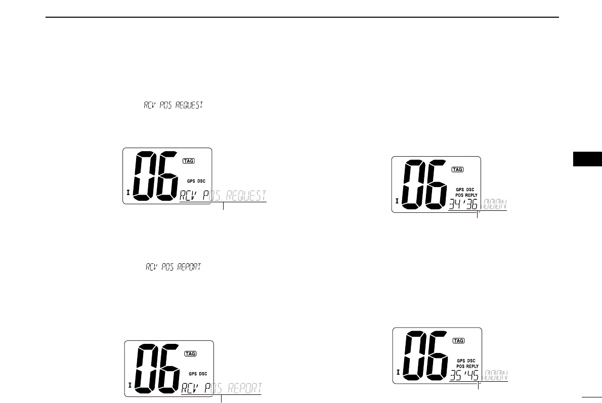
DReceiving a Position Request call
While monitoring Channel 70 and a Position Request call is
received:
➥“DSC” appears and “ ” scrolls at the chan-
nel comment indicator.
➥Push any key to stop the beep, then push [DSC•POS] to
reply to the call; push any other key to ignore the call.
DReceiving a Position Report call
While monitoring Channel 70 and a Position Report call is re-
ceived:
➥“DSC” appears and “ ” scrolls at the chan-
nel comment indicator.
➥Push any key to stop the beep, then push [DSC•POS] to
reply to the call; push any other key to ignore the call.
• The ‘Latitude’ and ‘Longitude’ from the called station is displayed
and scrolled automatically in order of Latitude co-ordinates and
then Longitude co-ordinates.
DReceiving a Position Reply call
While monitoring Channel 70 and a Position Reply call is re-
ceived:
➥“DSC” and “POS REPLY” appear in the display.
• The ‘Latitude’ and ‘Longitude’ from the called station is displayed
and scrolled automatically in order of Latitude co-ordinates and
then Longitude co-ordinates.
➥Push any key to stop the beep.
DReceiving a Position Report Reply call
While monitoring Channel 70 and a Position Report Reply call
is received:
➥“DSC” and “POS REPLY” appear in the display.
• The ‘Latitude’ and ‘Longitude’ you have sent is displayed and
scrolled automatically in order of Latitude co-ordinates and then
Longitude co-ordinates.
➥Push any key to stop the beep.
Scrolls
Scrolls
Scrolls
Scrolls
28
SET MODE
7
■Set mode programming
Set mode is used to change the conditions of the trans-
ceiver’s functions: Scan type (Normal or Priority,) Scan re-
sume timer, Weather alert, Dual/Tri-watch, DSC watch, Beep
tone, Auto acknowledgement and Favorite channel function.
Available functions may differ depending on dealer setting.
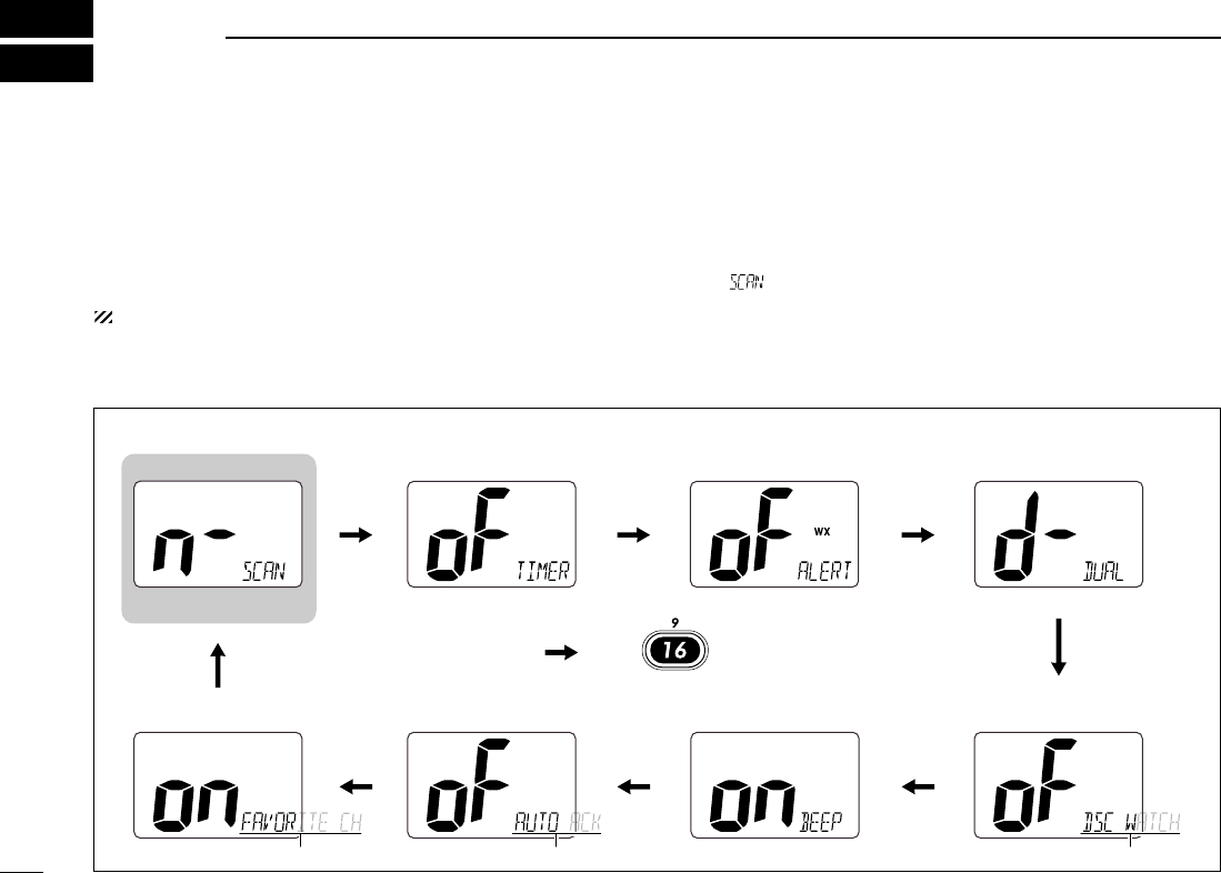
DSet mode operation
qTurn power OFF.
wWhile pushing [!6•9], turn power ON to enter Set mode.
• “ ” appears at the channel comment indicator.
eAfter the display appears, release [!6•9].
rPush [!6•9] to select the desired item, if necessary.
tPush [Y]or [Z]to select the desired condition of the item.
yTurn power OFF, then ON again to exit Set mode.
• Beep tone
Starting item
• Scan type • Scan resume timer • Weather alert • Dual/Tri-watch
• DSC watch• Auto acknowledgement
Scrolls
• Favorite channel function
Scrolls Scrolls
Push
DSet mode construction

29
7
SET MODE
7
■Set mode items
DScan type
The transceiver has 2 scan types: Normal scan and Priority
scan. Normal scan searches all TAG channels in the selected
channel group. Priority scan searches all TAG channels in se-
quence while monitoring Channel 16.
DDScan resume timer
The scan resume timer can be selected as a pause (OFF) or
timer scan (ON). When OFF is selected, the scan pauses
until the signal disappears. When ON is selected, the scan
pauses 5 sec. and resumes even if a signal has been re-
ceived on any other channel than Channel 16.
DDWeather alert
A NOAA broadcast station transmits a weather alert tone be-
fore important weather information. When the weather alert
function is turned ON, the transceiver detects the alert, then
the “WX ALT” indicator blinks until the transceiver is operated.
The previously selected (used) weather channel is checked
any time while scanning.
•“WX ALT” appears instead of “WX” indication when the function is
set ON.
DDDual/Tri-watch
This item can be selected as Dualwatch or Tri-watch. (p. 12)
Dualwatch (default) Tri-watch
Weather alert OFF (default) Weather alert ON
Scan timer OFF (default) Scan timer ON
Normal scan (default) Priority scan
30
7SET MODE
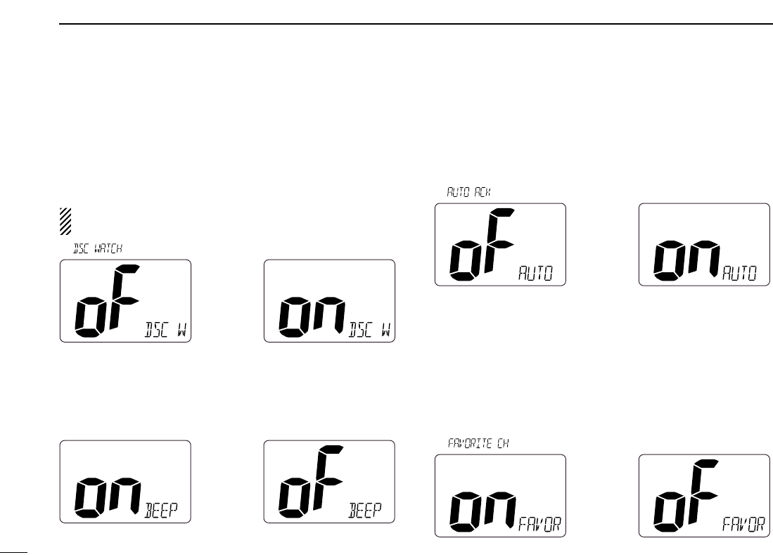
DDDSC watch
DSC watch monitors Channel 70 while you are receiving an-
other channel.
If a distress signal is received on Channel 70, the transceiver
monitors Channel 16 and 70 alternately until the distress sig-
nal disappears. If a signal is received on another channel,
DSC watch pauses until the signal disappears.
This function may not be available for some channel
groups depending on dealer setting.
• “ ” scrolls at the channel comment indicator.
DDBeep tone
You can select silent operation by turning beep tones OFF or
you can have confirmation beeps sound at the push of a key
by turning beep tones ON.
DDAutomatic acknowledgement
This item sets the Automatic acknowledgement function ON
or OFF.
When Position Request or Position Report call is received,
transceiver automatically transmits Position Request Reply or
Position Report Reply call, respectively.
• “ ” scrolls at the channel comment indicator.
DDFavorite channel
This item sets the Favorite channel function ON or OFF.
The favorite channel is programmed by the TAG channel set-
ting (p. 11).
When the Favorite channel function is turned ON, [YY]/[ZZ]
keys on the microphone select the favorite channels in the
selected channel group in sequence when pushed.
• “ ” scrolls at the channel comment indicator.
Favorite CH ON (default) Favorite CH OFF
Auto acknowledgement
OFF (default)
Auto acknowledgement
ON
Beep tone ON (default) Beep tone OFF
DSC watch OFF (default) DSC watch ON
31
8
CONNECTIONS AND MAINTENANCE
7
8
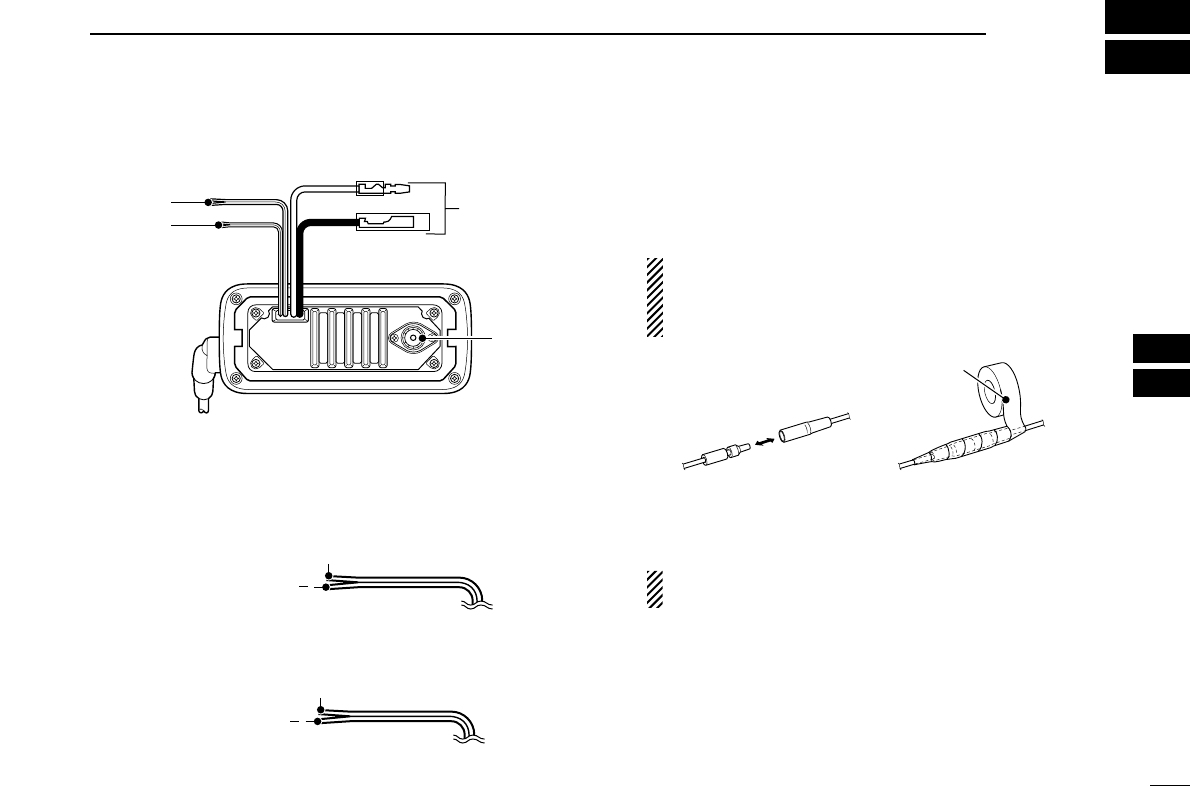
■Connections
qGPS RECEIVER LEAD
Connects to a GPS receiver for position indication.
• An NMEA0183 ver. 2.0 or 3.01 (sentence formatters RMC, GGA,
GNS, GLL) compatible GPS receiver is required. Ask your dealer
about suitable GPS receivers.
wEXTERNAL SPEAKER LEAD
Connects to an external speaker.
eDC POWER CONNECTOR
Connects the supplied DC power cable from this connector
to an external 13.8 V DC power source.
CAUTION: After connecting the DC power cable, GPS
receiver lead and external speaker lead, cover the con-
nector and leads with an adhesive tape as shown
below, to prevent water seeping into the transceiver.
rANTENNA CONNECTOR
Connects a marine VHF antenna with a PL-259 connector
to the transceiver.
CAUTION: Transmitting without an antenna may dam-
age the transceiver.
Rubber vulcanizing
tape
Blue: Speaker (+)
Gray: Speaker ( )
Yellow: NMEA IN (+)
Green: NMEA IN ( )
q
we
r
32
8CONNECTIONS AND MAINTENANCE
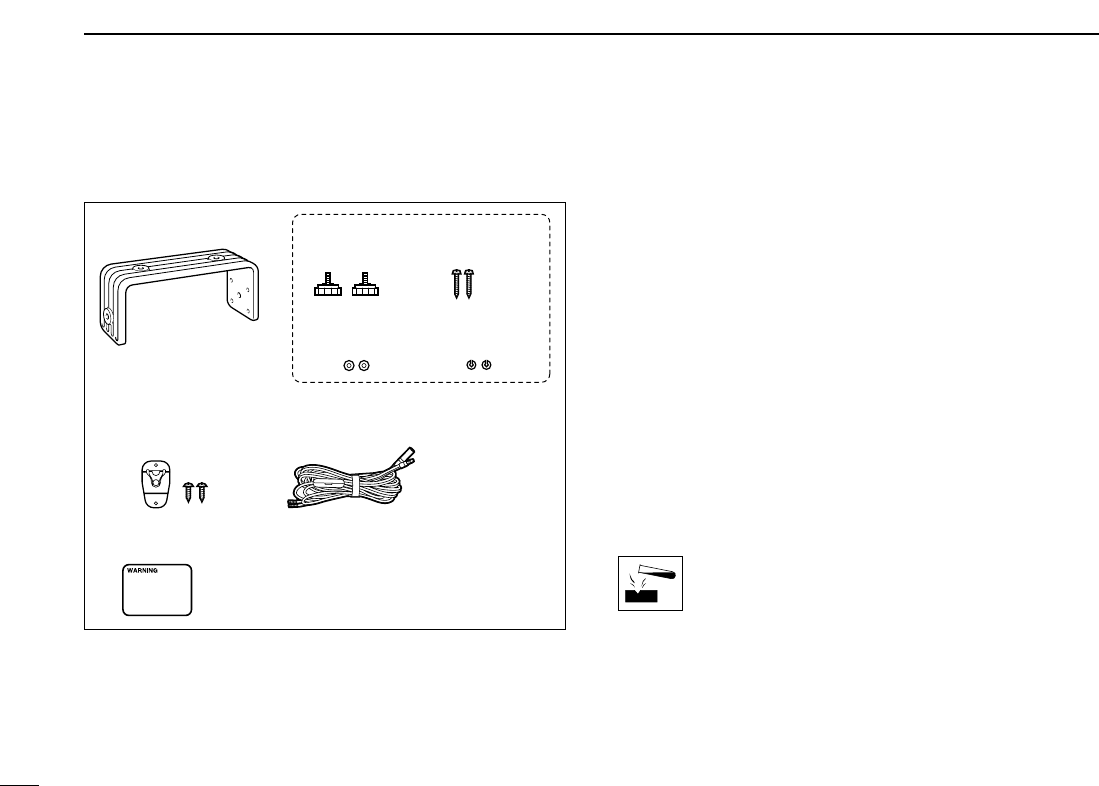
■Supplied accessories
The following accessories are supplied:
■Antenna
A key element in the performance of any communication sys-
tem is the antenna. Ask your dealer about antennas and the
best place to mount them.
■Fuse replacement
One fuse is installed in the supplied DC power cable. If a fuse
blows or the transceiver stops functioning, track down the
source of the problem, if possible, and replace the damaged
fuse with a new, rated one.
■Cleaning
If the transceiver becomes dusty or dirty, wipe it clean with a
soft, dry cloth.
AVOID the use of solvents such as benzene or al-
cohol, as they may damage transceiver surfaces.
Mounting bracket For mounting bracket
Knob bolts Screws (5×20)
Flat washers
(M5)
Spring washers
(M5)
Microphone hanger
and screws (3×16)
DC power cable
Warning sticker
33
8
CONNECTIONS AND MAINTENANCE
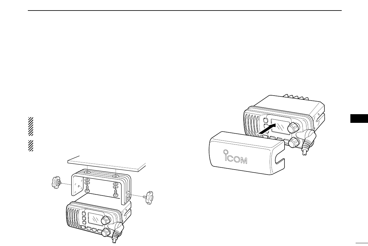
■Mounting the transceiver
DDUsing the supplied mounting bracket
The universal mounting bracket supplied with your transceiver
allows overhead or dashboard mounting.
• Mount the transceiver securely with the 2 supplied screws
(5 ×20) to a surface which is more than 10 mm thick and
can support more than 5 kg.
• Mount the transceiver so that the face of the transceiver is at
90° to your line of sight when operating it.
CAUTION: KEEP the transceiver and microphone at least
1 meter away from your vessel’s magnetic navigation com-
pass.
NOTE: Check the installation angle; the function display
may not be easy-to-read at some angles.
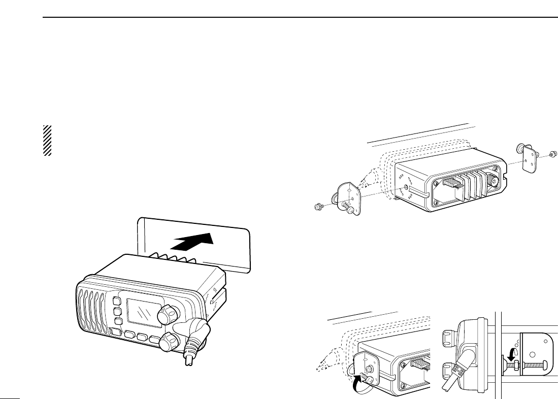
■Optional MB-92 attachment
An optional MB-92
DUST COVER
is available for attaching the
transceiver’s front panel to prevent the keys and knobs get-
ting wet when the transceiver is not used.
➥Attach the optional MB-92
DUST COVER
to the transceiver
as shown below.
8
EXAMPLE
34
8CONNECTIONS AND MAINTENANCE
■Optional MB-69 installation
An optional MB-69
FLUSH MOUNT
is available for mounting the
transceiver to a flat surface such as an instrument panel.
CAUTION: KEEP the transceiver and microphone at least
1 meter away from your vessel’s magnetic navigation com-
pass.
qUsing the template on p. 39, carefully cut a hole into the
instrument panel (or wherever you plan to mount the trans-
ceiver.)
wSlide the transceiver through the hole as shown below.
eAttach the clamps on either side of the transceiver with 2
supplied bolts (5 ×8 mm).
• Make sure that the clamps align parallel to the transceiver body.
rTighten the end bolts on the clamps (rotate clockwise) so
that the clamps press firmly against the inside of the in-
strument control panel.
tTighten the locking nuts (rotate counterclockwise) so that
the transceiver is securely mounted in position as below.
yConnect the antenna and power cable, then return the in-
strument control panel to its original place.

35
9
TROUBLESHOOTING
PROBLEM POSSIBLE CAUSE SOLUTION REF.
No sound from speaker. • Squelch level is too high.
• Volume level is too low.
• Speaker has been exposed to water.
p. 7
p. 7
—
• Set squelch to the threshold point.
• Set [VOL] to a suitable level.
• Drain water from the speaker.
The transceiver does
not turn ON.
• Bad connection to the power supply. p. 31• Check the connection to the transceiver.
Transmitting is impossi-
ble, or high power can
not be selected.
• Some channels are for low power or re-
ceive only.
• The output power is set to low.
pgs. 5,
6, 36
p. 7
• Change channels.
• Push [HI/LO] on the microphone to select
high power.
Scan does not start. • “TAG” channel is not programmed. • Set the desired channels as “TAG” channels. p. 11
No beeps. • Beep tones are turned OFF. • Turn the beep tone ON in Set mode. p. 30
Distress call cannot be
transmitted.
• MMSI (DSC self ID) code is not pro-
grammed.
• Program the MMSI (DSC self ID) code. p. 13
8
9

36
CHANNEL LIST
10
NOTE: Simplex channels, 3, 21, 23, 61, 64, 81, 82 and 83 CANNOT
be lawfully used by the general public in U.S.A. waters.
*1 Low power only. *2 Momentary high power. *3 DSC operation only.
Channel number Frequency (MHz)
03 156.150 160.75003
03A 156.150 156.150
156.200 160.80004
02 156.100 160.70002
04A 156.200 156.200
156.250 160.85005
05A 05A 156.250 156.250
06 06 156.300 156.30006
156.350 160.95007
07A 07A 156.350 156.350
08 08 156.400 156.40008
09 09 156.450 156.45009
10 10 156.500 156.50010
11 11 156.550 156.55011
12 12 156.600 156.60012
13*213*1
156.650 156.650
13
14 14
156.700 156.700
14
15*215*1
156.750 156.750
15*1
16 16
156.800 156.800
16
17*117*1
156.850 156.850
17
156.900 161.500
18
18A 18A
156.900 156.900
156.950 161.550
19
19A 19A 156.950 156.950
20 20*1157.000 161.60020
20A 157.000 157.000
01A 156.050 156.050
USA
01
156.050 160.65001
CAN
Transmit Receive
INT
Channel number Frequency (MHz)
157.100 161.70022
22A 22A 157.100 157.100
23 157.150 161.75023
21b Rx only 161.650
23A 157.150 157.150
24 24 157.200 161.80024
25 25 157.250 161.85025
25b Rx only 161.850
26 26 157.300 161.90026
27 27 157.350 161.95027
28 28 157.400 162.00028
28b Rx only 162.000
60 156.025 160.62560
156.075 160.67561
61A 61A 156.075 156.075
156.125 160.72562
62A 156.125 156.125
156.175 160.77563
63A 156.175 156.175
64 156.225 160.82564
64A 64A 156.225 156.225
156.275 160.87565
65A 65A 156.275 156.27565A
156.325 160.92566
66A 66A*1156.325 156.32566A
67*267 156.375 156.37567
21A 21A 157.050 157.050
USA
21 157.050 161.65021
CAN
Transmit Receive
INT
Channel number Frequency (MHz)
71 71 156.575 156.57571
72 72 156.625 156.62572
73 73 156.675 156.67573
70*370*3156.525 156.52570*3
74 74 156.725 156.72574
75*175*1156.775 156.77575*1
76*176*1156.825 156.82576*1
77*177*1156.875 156.87577
156.925 161.52578
78A 78A 156.925 156.925
156.975 161.57579
79A 79A 156.975 156.975
157.025 161.62580
80A 80A 157.025 157.025
157.075 161.67581
81A 81A 157.075 157.075
157.125 161.72582
82A 82A 157.125 157.125
83 157.175 161.77583
83A 83A 157.175 157.175
83b Rx only 161.775
84 84 157.225 161.82584
84A 157.225 157.225
85 85 157.275 161.87585
85A 157.275 157.275
86 86 157.325 161.92586
69 69 156.475 156.47569
68
USA
68 156.425 156.42568
CAN
Transmit Receive
INT
Channel number Frequency (MHz)
88 88 157.425 162.02588
88A 157.425 157.425
87A 157.375 157.375
87 87 157.375 161.97587
86A
USA
157.325 157.325
CAN
Transmit Receive
INT
Frequency (MHz)
RX only 162.425
RX only 162.450
RX only 162.500
RX only 162.475
RX only 162.525
RX only 161.650
RX only 161.775
RX only 163.275
RX only 162.400
RX only 162.550
Transmit Receive
WX channel
4
5
6
3
7
8
9
10
2
1

37
11
SPECIFICATIONS AND OPTIONS
10
11
■Specifications
ïïGeneral
• Frequency coverage : Transmit 156.025–157.425 MHz
Receive 156.050–163.275 MHz
• Mode : FM (16K0G3E)
DSC (16K0G2B)
• Channel spacing : 25 kHz
• Current drain (at 13.8 V) : TX (at 25 W) 5.5 A max.
Max. audio 1.5 A max.
• Power supply requirement : 13.8 V DC
• Frequency stability : ±10 ppm
• Operating temperature range: –20°C to +60°C; –4°F to +140°F
• Dimensions : 153(W) ×67(H) ×133(D) mm
(Projections not included) 6 1⁄32(W) ×2 5⁄8(H)×5 1⁄4(D) in
• Weight : Approx. 825 g ; 1.8 lb
ïïTransmitter
• Output power : 25 W and 1 W
• Modulation system : Variable reactance frequency modu-
lation
• Max. frequency deviation : ±5.0 kHz
• Spurious emissions : Less than –70 dBc @ 25 W
Less than –56 dBc @ 1 W
• Adjacent channel power : More than 70 dB
ïïReceiver
• Receive system : Double conversion
superheterodyne
• Sensitivity (12 dB SINAD) : 0.22 µV (typical)
• Squelch sensitivity : Less than 0.22µV
• Intermodulation rejection ratio : More than 70 dB
• Spurious response rejection ratio : More than 70 dB
• Adjacent channel selectivity : More than 70 dB
• Audio output power : 4.5 W (typical) at 10%
distortion with a 4 Ωload
All stated specifications are subject to change without notice or
obligation.
38
11 SPECIFICATIONS
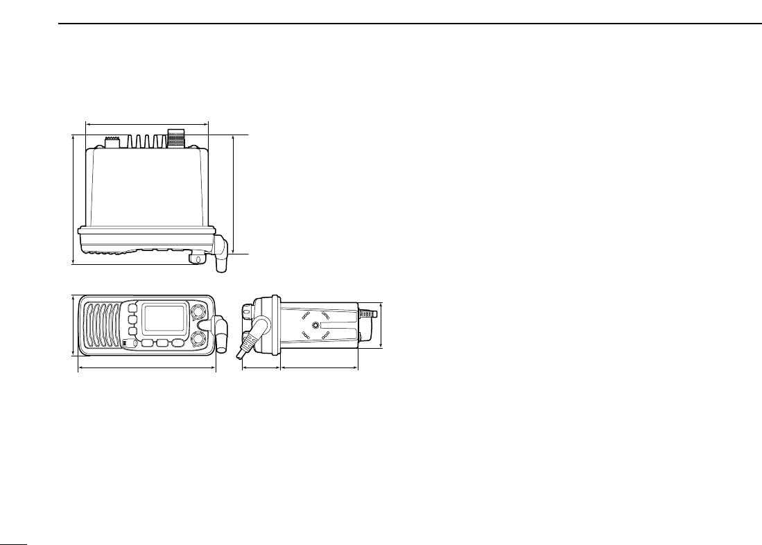
DDDimensions ■Options
•MB-69
FLUSH MOUNT KIT
For mounting the transceiver to a panel.
•MB-92
DUST COVER
For attaching to the front panel of the transceiver to protect it
when not in use.
Unit: mm (inch)
153.0 (6 1⁄32)
67.0 (2 5⁄8)143.5 (5 21⁄32)
51.0 (2)
42.2
(1 21⁄32)
86.3 (3 13⁄32)
137.0 (5 13⁄32)
133 (5 1⁄4)
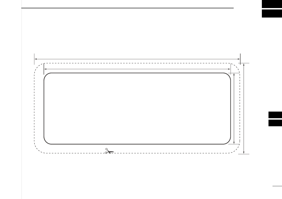
39
12
TEMPLATE
11
12
Unit: mm (inch)
153.0 (6 1⁄32)
139.0 (5 15⁄32)
67.0 (2 5⁄8)
53.0 (2 3⁄32)
Cut here

MEMO

1-1-32 Kamiminami, Hirano-ku, Osaka 547-0003, Japan
A-6542D-1US
Printed in Japan
©2006 Icom Inc.