ICOM orporated 301500 HF/50 MHz Transceiver User Manual IC 718 Instruction Manual
ICOM Incorporated HF/50 MHz Transceiver IC 718 Instruction Manual
UserManual.wiki
>
ICOM orporated
>
301500 User Manual
User Manual
Navigation menu
Upload a User Manual
Namespaces
Wiki Guide
HTML
PDF
Info
Views
User Manual
Discussion / Help
Navigation
![IMPORTANTREAD THIS INSTRUCTION MANUAL CAREFULLY before attempting to operate the transceiver.SAVE THIS INSTRUCTION MANUAL. This manual contains important safety and operating in-structions for the IC-7200.FOREWORDWe understand that you have a choice of many differ-ent radios in the market place. We want to take a cou-ple of moments of your time to thank you for making the IC-7200 your radio of choice, and hope you agree with Icom’s philosophy of “technology first.” Many hours of research and development went into the de-sign of your IC-7200.D FEATURESM IF DSP featuresM Digital Twin PBTM Manual notch functionM ±0.5 ppm of high frequency stabilityM Simple operationM Tough and compact bodyM Standard voice synthesizerEXPLICIT DEFINITIONSWORD DEFINITIONRWARNING Personal injury, fire hazard or electric shock may occur.CAUTION Equipment damage may occur.NOTEIf disregarded, inconvenience only. No risk of personal injury, fire or electric shock.SUPPLIED ACCESSORIESThe transceiver comes with the following accessories.Qty.q Hand microphone (HM-36) ............................. 1w DC power cable (OPC-1457) .......................... 1e Spare fuse (ATC 5 A) ...................................... 1r Spare fuse (ATC 30 A) .................................... 2t ACC cable ......................................................... 1y 3.5 (d) mm plug ................................................. 1u 6.3 (d) mm Electronic keyer plug ...................... 1i Microphone hanger ........................................... 1o Jack cap (for [PHONES]) ................................. 1qetwyurioFCC INFORMATION• FOR CLASS B UNINTENTIONAL RADIATORS:This equipment has been tested and found to comply with the limits for a Class B digital device, pursuant to part 15 of the FCC Rules. These limits are designed to provide reasonable protection against harmful in-terference in a residential installation. This equipment generates, uses and can radiate radio frequency en-ergy and, if not installed and used in accordance with the instructions, may cause harmful interference to radio communications. However, there is no guaran-tee that interference will not occur in a particular in-stallation. If this equipment does cause harmful inter-ference to radio or television reception, which can be determined by turning the equipment off and on, the user is encouraged to try to correct the interference by one or more of the following measures: • Reorient or relocate the receiving antenna. • Increase the separation between the equipment and receiver. • Connect the equipment into an outlet on a circuit different from that to which the receiver is con-nected. • Consult the dealer or an experienced radio/TV technician for help.i](https://usermanual.wiki/ICOM-orporated/301500/User-Guide-977157-Page-2.png)
![PRECAUTIONSR WARNING RF EXPOSURE! This device emits Radio Frequency (RF) energy. Extreme caution should be observed when operating this device. If you have any questions regarding RF exposure and safety standards please refer to the Federal Com-munications Commission Office of Engineering and Technology’s report on Evaluating Compliance with FCC Guidelines for Human Radio Frequency Electro-magnetic Fields (OET Bulletin 65).R WARNING HIGH VOLTAGE! NEVER touch an antenna or internal antenna connector during trans-mission. This may result in an electrical shock or burn.R WARNING! NEVER operate the transceiver while driving a vehicle. Safe driving requires your full attention—anything less may result in an accident.R NEVER apply AC power to the [DC13.8V] socket on the transceiver rear panel. This could cause a fire or damage the transceiver.R NEVER apply more than 16 V DC, such as a 24 V battery, to the [DC13.8V] socket on the transceiver rear panel. This could cause a fire or damage the transceiver.R NEVER let metal, wire or other objects touch any internal part or connectors on the rear panel of the transceiver. This may result in an electric shock or this could cause a fire or damege the transceiver.R NEVER expose the transceiver to rain, snow or any liquids.DO NOT use or place the transceiver in areas with temperatures below –10°C (+14°F) or above +60°C (+140°F). Be aware that temperatures on a vehicle’s dashboard can exceed +80°C (+176°F), resulting in permanent damage to the transceiver if left there for extended periods.DO NOT place the transceiver in excessively dusty environments or in direct sunlight.DO NOT place the transceiver against walls or put anything on top of the transceiver. This will obstruct heat dissipation.Place unit in a secure place to avoid inadvertent use by children.During mobile operation, NEVER place the trans-ceiver where air bag deployment may be obstructed.During mobile operation, DO NOT place the trans-ceiver where hot or cold air blows directly onto it.During mobile operation, DO NOT operate the trans-ceiver without running the vehicle’s engine. When the transceiver’s power is ON and your vehicle’s engine is OFF, the vehicle’s battery will quickly become ex-hausted.Make sure the transceiver power is OFF before start-ing the vehicle engine. This will avoid possible dam-age to the transceiver by ignition voltage spikes.During maritime mobile operation, keep the trans-ceiver and microphone as far away as possible from the magnetic navigation compass to prevent errone-ous indications.BE CAREFUL! The rear panel will become hot when operating the transceiver continuously for long peri-ods.BE CAREFUL! If a linear amplifier is connected, set the transceiver’s RF output power to less than the linear amplifier’s maximum input level, otherwise, the linear amplifier will be damaged.Use Icom microphones only (supplied or optional). Other manufacturer’s microphones have different pin assignments, and connection to the IC-7200 may damage the transceiver.For U.S.A. onlyCaution: Changes or modifications to this trans-ceiver, not expressly approved by Icom Inc., could void your authority to operate this transceiver under FCC regulations.Icom, Icom Inc. and the logo are registered trademarks of Icom Incorporated (Japan) in the United States, the United King-dom, Germany, France, Spain, Russia and/or other countries.ii](https://usermanual.wiki/ICOM-orporated/301500/User-Guide-977157-Page-3.png)
![iiiTABLE OF CONTENTSIMPORTANT ............................................................... iFOREWORD .............................................................. iEXPLICIT DEFINITIONS ............................................ iSUPPLIED ACCESSORIES....................................... iFCC INFORMATION .................................................. iPRECAUTIONS ......................................................... iiTABLE OF CONTENTS ........................................... iv1 PANEL DESCRIPTION................................... 1−11N Front panel ........................................................ 1 D Keypad .......................................................... 5N Function display ................................................ 7N Rear panel ......................................................... 9 D ACC socket information .............................. 10N Microphones .................................................... 11 D HM-36 ......................................................... 11 D SM-20 ......................................................... 112 INSTALLATION AND CONNECTIONS ........ 12−20N Unpacking ....................................................... 12N Selecting a location ......................................... 12N Grounding ....................................................... 12N Antenna connection ........................................ 12N Required connections...................................... 13N Advanced connections .................................... 14N Power supply connections ............................... 15N Connecting the DC Power Supply ................... 15N Battery connections ......................................... 15N External antenna tuners .................................. 16N Linear amplifier connections............................ 17NConnections for CW ........................................ 18NConnections for RTTY ..................................... 19 D Connections for RTTY (FSK) ...................... 19 D Connections for RTTY (AFSK) .................... 19NConnections for SSTV or PSK31 .................... 20 D When connecting to the [ACC] socket ......... 20 D When connecting to the [MIC] connector .... 203 BASIC OPERATION ..................................... 21−32N When first applying power (CPU resetting) ..... 21N Initial settings .................................................. 21N VFO description ............................................... 22N VFO operation ................................................. 22 D Selecting the VFO A/B ................................ 22 D VFO equalization ......................................... 22N Selecting VFO/memory mode ......................... 23 D Differences between VFO mode and memory mode ............................................. 23N Selecting an operating band ........................... 24 D Using the band stacking register ................. 24N Frequency setting ............................................ 25 D Using the main dial ..................................... 25 D Direct frequency entry with keypad ............. 25 D Programmable tuning steps ........................ 26 D Selecting the programmable tuning step..... 26 D 1 Hz and 10 Hz tuning steps ....................... 27 D TS switch flow chart ................................. 27 D Auto tuning step function ............................ 28 D ¼ tuning function (SSB data/AM data/CW/RTTY only) ........... 28 D Band edge warning beep ............................ 28N Volume setting ................................................. 29N Operating mode selection ............................... 29N Dial lock function ............................................. 29N RF gain and Squelch ....................................... 30N Meter function ................................................. 30N Basic transmit operation .................................. 31 D Transmitting ................................................. 31 D Output power and Microphone gain settings .. 31N Voice synthesizer function ............................... 324 RECEIVE AND TRANSMIT .......................... 33−43N Operating SSB ................................................ 33 D Convenient functions for receive ................. 33 D Convenient functions for transmit ................ 34 D About 5 MHz band operation (USA version only) ...................................... 34N Operating CW ................................................. 35 D Convenient functions for receive ................. 36 D Convenient functions for transmit ................ 36 D CW reverse mode ....................................... 37 D CW pitch control .......................................... 37 D CW side tone function ................................. 38 D Keying speed setting ................................... 38NOperating RTTY (FSK) .................................... 39 D Convenient functions for receive ................. 39 D RTTY reverse mode .................................... 40 D Twin peak filter ............................................ 40 D RTTY decode set mode .............................. 41N Operating AM .................................................. 42 D Convenient functions for receive ................. 42 D Convenient functions for transmit ................ 42N Data mode (SSTV/PSK31) operation .............. 43](https://usermanual.wiki/ICOM-orporated/301500/User-Guide-977157-Page-4.png)
![5 FUNCTIONS FOR RECEIVE ........................ 44−52N RIT function ..................................................... 44N Preamp and attenuator ................................... 45N AGC function ................................................... 45 D AGC time constant selection ....................... 45N Twin PBT operation ......................................... 46N IF filter selection .............................................. 47 D IF filter selection .......................................... 47 D FIlter passband width setting ...................... 48 D IF fIlter shape (SSB/CW only) ..................... 48N Noise blanker .................................................. 49 D Noise blanker settings ................................. 49N Noise reduction ............................................... 50 D Noise reduction level setting ....................... 50N Notch function ................................................. 51 D Auto notch function ..................................... 51 D Manual notch function ................................. 51 D Manual notch filter setting ........................... 526 FUNCTIONS FOR TRANSMIT ..................... 53−60N VOX function .................................................... 53 D Adjusting the VOX function.......................... 53 D VOX set mode ............................................. 54N Break-in function ............................................. 55 D Semi break-in operation .............................. 55 D Full break-in operation ................................ 56N Speech compressor ........................................ 57 D Compression level setting ........................... 57N Split frequency operation ................................ 58 D Quick split function ...................................... 59 D Split lock function ........................................ 59NMeasuring SWR .............................................. 607 MEMORY OPERATION ................................ 61−64NMemory channels ............................................ 61NMemory channel selection .............................. 61NMemory programming ..................................... 62 D Programming in VFO mode ........................ 62 D Programming in memory mode ................... 62NFrequency copying .......................................... 63 D Memory ¶ VFO ........................................... 63NMemory clearing ............................................. 648 SCAN OPERATION ...................................... 65−66N Scan types ...................................................... 65N Preparation ...................................................... 65N Programmed scan operation (VFO mode) ...... 66N Memory scan operation (Memory mode) ........ 669 ANTENNA TUNER OPERATION ................. 67−69N Optional AT-180 AUTOMATIC ANTENNA TUNER operation ......................................................... 67 D Tuner operation ........................................... 67 D Manual tuning ............................................. 67N AT-180 internal switch description ................... 68N Optional AH-4 AUTOMATIC ANTENNA TUNER operation ......................................................... 69 D AH-4 operation ............................................ 6910 SET MODE ................................................... 70−82N General ........................................................... 70 D Quick set mode operation ........................... 70 D Set mode operation ..................................... 70N Quick set mode ............................................... 71N Set mode ......................................................... 74 D Paddle operation from [MIC] connector ...... 8211 MAINTENANCE ........................................... 83−84N Fuse replacement ........................................... 83 D DC power cable fuse replacement .............. 83 D Circuitry fuse replacement .......................... 83N Memory backup ............................................... 84N Resetting the CPU .......................................... 84N Cleaning .......................................................... 8412 TROUBLESHOOTING .................................. 85−8613 OPTION INSTALLATIONS ................................. 87N MB-116 HANDLES installation ........................... 87N MB-117 CARRYING HANDLE installation ............. 87N MB-118 MOBILE MOUNTING BRACKET installation.. 8714 CONTROL COMMAND ................................ 88−90N Remote jack (CI-V) information ....................... 88 D CI-V connection example ............................ 88 D Data format ................................................. 88 D Command table ........................................... 8915 SPECIFICATIONS .............................................. 91N General ........................................................... 91N Transmitter ....................................................... 91N Receiver .......................................................... 9116 OPTIONS ...................................................... 92−9317 ABOUT CE ................................................... 94−95iv123456789101112131415161718192021](https://usermanual.wiki/ICOM-orporated/301500/User-Guide-977157-Page-5.png)
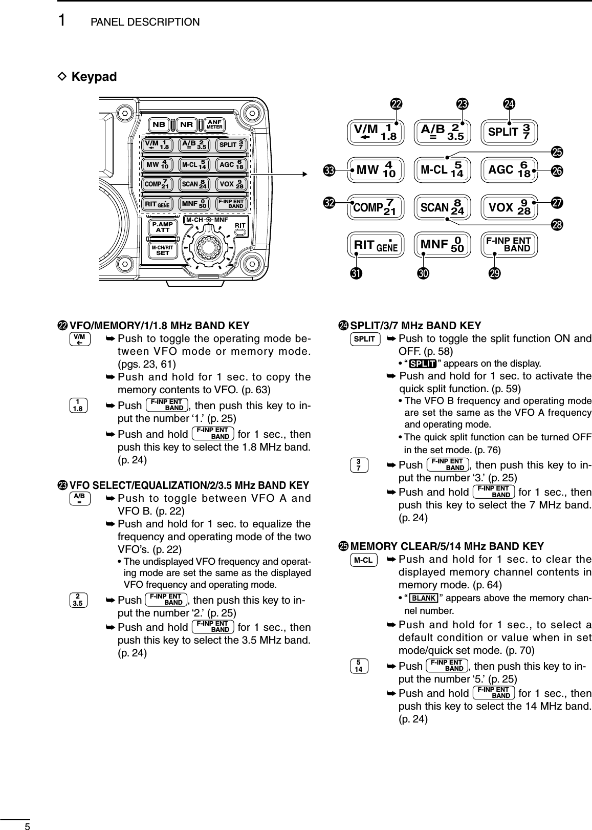
![q PASSBAND TUNING CONTROLS [TWIN PBT] Adjust the receiver’s DSP filter passband width. (p. 46) • The limit of the variable range depends on the pass-band width and mode. The limit of the variable range is half of the passband width, and PBT is adjustable in 25 Hz steps. What is the PBT control?Generally, the PBT electronically narrows the IF passband width to reject interference. This trans-ceiver uses the DSP circuit for the PBT function.PBT2PBT1Low cutHigh cut CenterTWIN PBT TWIN PBT TWIN PBT–+w NOISE BLANKER KEY NB (p. 49) ± Push to turn the noise blanker function ON or OFF. • “ ” appears on the display. ± Push and hold for 1 sec to enter the noise blanker set mode; push again to return to normal operation. • Before entering the noise blanker set mode, the noise blanker function is turned ON. What is the noise blanker?The noise blanker reduces pulse-type noise such as that generated by automobile ignition systems. This function is not effective against non pulse-type noise.e NR KEY NR (p. 50) ± Push to turn the noise reduction function ON or OFF. • “ ” appears on the display. ± Push and hold for 1 sec. to enter the noise re-duction level set mode; push again to return to normal operation. • Before entering the noise reduction set mode, the noise reduction function is turned ON. What is the Noise Reduction function?The Noise Reduction (NR) function removes ran-dom noise from the receiver passband. The level is adjustable to allow maximum clarity without harm-ing the intelligibility of the desired signal. Noise Re-duction should generally not be used with digital modes.11PANEL DESCRIPTIONi7200MODETUNERTSFILTERSPCHV/MA/BSPLITM-CLSCANSETATTP.AMPCOMPVOXMNFRIT123456780502818141021 24=73.51.8F-INPM-CH/RITENTBANDGENE9.AGCMWANFMETERNRNBSpeaker trewFunctionDisplay (p. 7)uiyqoN Front panel](https://usermanual.wiki/ICOM-orporated/301500/User-Guide-977157-Page-6.png)
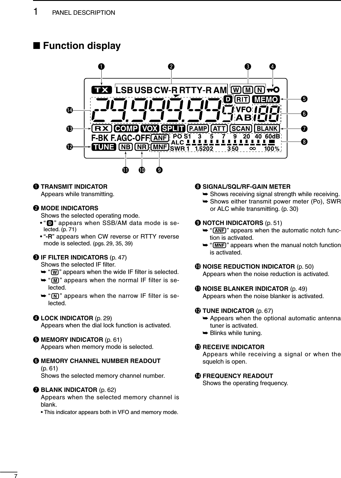
![2r ANF/METER KEY ANFMETER (p. 51) ± Push to turn the Automatic Notch Filter function ON or OFF in SSB and AM modes. • “ ” appears on the display. ± Push and hold for 1 sec. to toggle the meter function; (pgs. 30, 60) PO « SWR « ALC • PO : indicates the relative RF output power. • SWR : indicates the SWR over the transmission line. • ALC : Indicates ALC level. What is the Automatic Notch Filter?The Automatic Notch Filter is a narrow DSP filter that automatically identifies and attenuates beat tones, tun-ing signals, CW, etc., even if they are moving and re-moves them from the receiver passband while pre-serving the desired signal’s frequency response.t KEYPAD ± V/M, A/B=, SPLIT, MW, M-CL, AGC, COMP, SCAN, VOX, RIT and MNF keys are available. (p. 5) ± After pushing and holding F-INP ENTBAND for 1 sec., push a key on the keypad to select the operating band. (p. 24) • The band stacking register is available. • •GENE selects the general coverage band. ± After pushing F-INP ENTBAND , push a key on the key-pad to enter a numeric frequency. After entering, push F-INP ENTBAND . (p. 25) • e.g. To enter 14.195 MHz; Push F-INP ENTBAND , 11.8 , 410 , •GENE , 11.8 , 928 , 514 and F-INP ENTBAND .y RIT CONTROL INDICATOR (pgs. 44, 61) Lights red when [M-CH] control (u) acts as the RIT control.u M-CH/RIT CONTROL [M-CH] (inner control) ± While in the set mode/quick set mode, rotate to select the set mode item. (p. 70) ± This control can act as the memory channel control or RIT control. • The RIT function should be turned ON in advance to activate this control as RIT control. (p. 44) - “” appears when the RIT function is turned ON. • The RIT control indicator (y) lights red when this control is activated as the RIT control. During [M-CH] acts as the M-CH control: Rotate to select a memory channel (p. 61).OFFM-CHChannel decreasesChannel increases During [M-CH] acts as RIT control: Rotate to shift the receive frequency (p. 44). • Rotate the control clockwise to incerase the fre-quency, or rotate the control counterclockwise to de-crease the frequency. • The shift frequency range is ±9.999 kHz in 1 Hz steps (or ±9.99 kHz in 10 Hz steps).Lights redRITFrequency decreasesFrequency increases What is the RIT function?The RIT (Receiver Incremental Tuning) shifts the re-ceive frequency without shifting the transmit frequency.This is useful for fine tuning for stations calling you off-frequency or when you prefer to listen to slightly different sounding voice characteristics, etc. • About the [M-CH] control activation:RIT control indicator (y on p. 2)Lights OFF indicator(!6 on p. 8) Appears Acts as the RIT control Acts as the mem-ory channel controlDisappears N/Ai MANUAL NOTCH FILTER CONTROL [MNF] (outer control; p. 51) Rotate to adjust the notch filter frequency to reject an interfering signal while the manual notch func-tion is ON.High frequencyLow frequency What is the Manual Notch Filter?The Manual Notch Filter is an adjustable narrow DSP filter that removes tones from CW, SSB or AM signals while preserving the desired signal’s fre-quency response.o M-CH/RIT•SET KEY M-CH/RITSET ± Push to set the [M-CH] control to RIT control. • The RIT function should be turned ON in advance. (p. 44) • The RIT control indicator (y) lights red when the [M-CH] control functions as the RIT control. ± Push and hold for 1 sec. to enter the quick set mode. (p. 70) ± During quick set mode, push and hold for 1 sec. to enter the set mode (p. 70) ± During quick/set mode, push to return to normal operation. (p. 70)1PANEL DESCRIPTION123456789101112131415161718192021](https://usermanual.wiki/ICOM-orporated/301500/User-Guide-977157-Page-7.png)
![3!0 MODE KEY MODE (p. 29) ± Push momentarily to cycle through the operating modes: USB/LSB « CW/CW-R « RTTY/RTTY-R « AM ± Push and hold for 1 sec. to toggle the following operating modes: USB ¢ LSB (p. 33) CW ¢ CW-R (Reverse) (p. 35) RTTY ¢ RTTY-R (Reverse) (p. 39) • “CW-R” or “RTTY-R” appears on the display when reverse mode is selected. Undesired modes can be inhibited in set mode. (p. 81)!1 TUNING STEP KEY TS (pgs. 26, 27) ± Push to turn the programmable tuning step ON or OFF. • “√” appears above the 1 kHz indicator when the pro-grammable tuning step is turned ON and the fre-quency can be changed in programmed kHz steps. ± While the programmable tuning step is turned ON (“√” appears), push and hold for 1 sec. to enter tuning step set mode; push again to return to normal operation. • 0.1, 1, 5, 9 and 10 kHz programmable tuning steps are available. ± While the programmable tuning step is turned OFF, push and hold for 1 sec. to turn the 1 Hz step ON and OFF. • 1 Hz indication appears, and the frequency can be changed in 1 Hz steps.!2 PREAMP/ATTENUATOR KEY P.AMPATT (p. 45) ± Push to turn the preamp ON or OFF. • “ ” appears on the display. ± Push and hold for 1 sec. to turn the 20 dB atten-uator ON; push momentarily to turn the attenua-tor OFF. • “ ” appears on the display. What is the preamp?The preamp amplifies signals in the receiver front end (input) circuit to improve the sensitivity. Turn the preamp ON when receiving weak signals. What is the attenuator?The attenuator prevents a strong undesired signal near the desired frequency or near your location, such as from a broadcast station, from causing dis-tortion or spurious signals.!3 MAIN DIAL [DIAL] Changes the displayed frequency and selects val-ues for selected set mode items, etc.!4 FILTER KEY FILTER (p. 47) ± Push momentarily to cycle the IF filter settings between wide, middle and narrow for the se-lected operating mode. ± Push and hold for 1 sec. to enter the filter set mode.i7200MODETUNERTSFILTERSPCHV/MA/BSPLITM-CLSCANSETATTP.AMPCOMPVOXMNFRIT123456780502818141021 24=73.51.8F-INPM-CH/RITENTBANDGENE9.AGCMWANFMETERNRNBSpeakerFunctionDisplay (p. 7)!3@1 !5 !4!6!7!9 !8@0!1!0!2N Front panel (Continued)1PANEL DESCRIPTION](https://usermanual.wiki/ICOM-orporated/301500/User-Guide-977157-Page-8.png)
![41PANEL DESCRIPTION123456789101112131415161718192021!5 SPCH•LOCK KEY SPCH ± Push to announce the selected frequency and S-meter level by the speech synthesizer. (p. 32) • The parameters to be announced can be selected in the set mode. (p. 77) ± Push and hold for 1 sec. to turn the dial lock function ON or OFF. (p. 29) • The dial lock function electronically locks the main dial. • “ ” appears while the dial lock function is ON.!6 POWER KEY ± Push to turn power ON. • Turn the DC power supply ON in advance. ± Push and hold for 1 sec. to turn power OFF.!7 TUNER KEY TUNER (p. 67) ± Push to turn the automatic antenna tuner func-tion ON or OFF. • An optional antenna tuner must be connected. • “ ” appears on the display. ± Push and hold for 1 sec. to manually tune the antenna tuner. • An optional antenna tuner must be connected. • When the tuner cannot tune the antenna, the tuning circuit is bypassed automatically after 20 sec.!8 RF GAIN/SQUELCH CONTROL [RF/SQL] (outer control; p. 30) ± Adjusts the RF gain and squelch threshold level. ± The squelch removes noise output from the speaker (closed condition) when no signal is re-ceived. • The squelch is available for all modes. • The control can be set as the squelch plus RF gain controls, squelch control only (RF gain is fixed at maximum) or Auto (RF gain control in SSB, CW and RTTY; squelch control in AM) in set mode.MODE SET MODE SETTINGAUTO SQL RF + SQLSSB, CWRTTY RF GAIN SQL RF GAIN + SQLAM SQL SQL RF GAIN + SQLMinimum RF gainAdjustable rangeRF gain adjustablerangeMaximum RF gainMaximum RF gainSquelch is open. S-meter squelchS-meter squelchthresholdLowest threshold Highest thresholdSquelch is open.S-meter squelchS-meter squelchthreshold• When functioning as RF GAIN/SQL control• When functioning as RF GAIN control(Squelch is fixed open; SSB, CW, RTTY only)• When functioning as SQL control(RF gain is fixed at maximum.)!9 AF CONTROL [AF] (inner control; p. 29) Varies the audio output level from the speaker.Audio outputdecreasesAudio outputincreases@0 HEADPHONE JACK [PHONES] Accepts headphones with 8–16 Ω impedance. • Output power: 5 mW with an 8 Ω load. • When headphones are connected, no receive audio comes from the speaker.@1 MICROPHONE CONNECTOR [MIC] Accepts supplied or optional microphone. • See p. 11 for appropriate microphones and microphone connector information.](https://usermanual.wiki/ICOM-orporated/301500/User-Guide-977157-Page-9.png)
![61PANEL DESCRIPTION123456789101112131415161718192021@6 AGC/6/18 MHz BAND KEY AGC ± Push to toggle the time constant for the AGC circuit fast and slow. (p. 45) • “F. AGC ” appears on the display when fast AGC is selected; no indication ap-pears when slow AGC is selected ± Push and hold for 1 sec. to turn the AGC function OFF. • “AGC-OFF” appears on the display. 618 ± Push F-INP ENTBAND , then push this key to input the number ‘6.’ (p. 25) ± Push and hold F-INP ENTBAND for 1 sec., then push this key to select the 18 MHz band. (p. 24)@7 VOX/9/28 MHz BAND KEY VOX ± Push to turn the VOX function ON or OFF. (p. 53) ± Push and hold for 1 sec. to enter VOX set mode; push again to return to nor-mal operation. 928 ± Push F-INP ENTBAND , then push this key to input the number ‘9.’ (p. 25) ± Push and hold F-INP ENTBAND for 1 sec., then push this key to select the 28 MHz band. (p. 24) What is the VOX function?The VOX function (Voice-Operated Transmission) activates the transmitter when you speak into the microphone and automatically returns to receive when you stop speaking.@8 SCAN/8/24 MHz BAND KEY SCAN Push to start/stop the programmed/memory scan in VFO/memory mode. (p. 66) • “” appears on the display during scanning. 824 ± Push F-INP ENTBAND , then push this key to input the number ‘8.’ (p. 25) ± Push and hold F-INP ENTBAND for 1 sec., then push this key to select the 24 MHz band. (p. 24)@9 FREQUENCY INPUT/ENTER/BAND KEY F-INP ENTBAND ± Push to enter the direct frequency in-put condition. (p. 25) ± Push and hold for 1 sec., then push a key on the keypad to select the oper-ating band. (p. 24) • •GENE selects the general coverage band.#0 MANUAL NOTCH FILTER/0/50 MHz BAND KEY MNF ± Push to turn the manual notch filter func-tion ON or OFF. (p. 51) • “ ” appears on the display. ± Push and hold for 1 sec. to enter the manual notch set mode; push again to return to normal operation. (p. 51) • Before entering the set mode, the manual notch filter function is turned ON. 050 ± Push F-INP ENTBAND , then push this key to in-put the number ‘0.’ (p. 25) ± Push and hold F-INP ENTBAND for 1 sec., then push this key to select the 50 MHz band. (p. 24)#1 RIT/•/GENERAL BAND KEY RIT ± Push to turn the RIT (Receiver Incremen-tal Tuning) function ON or OFF. (p. 44) • “ ” appears on the display. • RIT frequency can be adjusted with [M-CH] control when RIT mode is selected. ± Push and hold for 1 sec. to add the RIT shift frequency to the operating fre-quency. (p. 44) • Available only when the XFC (transmit fre-quency check function) is turned OFF. (p. 76) •GENE ± Push F-INP ENTBAND , then push this key to in-put the number ‘• (decimal point).’ (p. 25) ± Push and hold F-INP ENTBAND for 1 sec., then push this key to select the general cover-age band. (p. 24)#2 SPEECH COMPRESSOR/7/21 MHz BAND KEY COMP ± Push to turn the speech compressor function ON or OFF. (p. 57) • “ ” appears on the display. ± Push and hold for 1 sec. to enter the speech compression level set mode; push again to return to normal operation. 721 ± Push F-INP ENTBAND , then push this key to in-put the number ‘7.’ (p. 25) ± Push and hold F-INP ENTBAND for 1 sec., then push this key to select the 21 MHz band. (p. 24)#3 MEMORY WRITE/4/10 MHz BAND KEY MW Push and hold for 1 sec. to store the dis-played VFO frequency and operating mode into the selected memory channel. (p. 62) 410 ± Push F-INP ENTBAND , then push this key to in-put the number ‘4.’ (p. 25) ± Push and hold F-INP ENTBAND for 1 sec., then push this key to select the 10 MHz band. (p. 24)](https://usermanual.wiki/ICOM-orporated/301500/User-Guide-977157-Page-11.png)
![9q TUNER CONTROL SOCKET [TUNER] (p. 16) Accepts the control cable from an optional AH-4 HF/50 MHz AUTOMATIC ANTENNA TUNERw GROUND TERMINAL [GND] (p. 12) Connect this terminal to a ground to prevent elec-trical shocks, TVI, BCI and other problems.e DC POWER SOCKET [DC 13.8V] (p. 15) Accepts 13.8 V DC through the supplied DC power cable.Rear panel viewr USB JACK [ ] Connect the USB cable to be used for the modula-tion input (p. 77), the transceiver operation with PC (available in the near future), etc.t EXTERNAL SPEAKER JACK [EXT SP] (p. 91) Connect a 4–8 ø external speaker, if desired. • When an external speaker is connected, the internal speaker does not function.y CI-V REMOTE CONTROL JACK [REMOTE] (p. 88) ± Designed for use with a PC for remote control of the transceiver functions. ± Used for transceiver operation with another Icom CI-V transceiver or receiver.u ANTENNA CONNECTOR [ANT] (p. 13) Accepts a 50 Ω antenna with a PL-259 connector and a 50 Ω coaxial cable.i ALC INPUT JACK [ALC] (p. 17) Connects to the ALC output jack of a non-Icom lin-ear amplifier.o SEND CONTROL JACK [SEND] (p. 17) Goes to ground while transmitting to control exter-nal equipment such as a linear amplifier. • Max. control level: 16 V DC/0.5 A!0 ELECTRONIC KEYER JACK [KEY] Accepts a key or paddle connector for the internal electronic keyer. • The keyer type selection between the internal elec-tronic keyer and straight key operation can be made in set mode.When connectinga straight keyWhen connectinga paddle(dot)(com)(dash)() If you use an external electronic keyer, make sure the output voltage of the keyer is less than 0.4 V when keying the transmitter.!1 ACCESSORY SOCKET [ACC] (p. 10) Enables connection to external equipment such as a TNC for data communications, a linear amplifier or an automatic antenna tuner, etc. • See page 10 for socket wiring information.DC 13.8V ACC KEY SEND ALC ANTREMOTE EXT SPGNDTUNERqwe rtyuio!0!1N Rear panel1PANEL DESCRIPTION](https://usermanual.wiki/ICOM-orporated/301500/User-Guide-977157-Page-14.png)
![10D ACC socket information• ACC socketACCPIN No.NAME DESCRIPTION SPECIFICATIONS12348765910 11 1213Rear panel viewColor refers to the cable strands of the supplied cable.q brownw rede oranger yellowt greeny blueu purpleio!0!1!2!3graywhiteblackpinklightbluelightgreen1 NC ——— ———2 GND Connects to ground. ———3HSENDInput/output pin.Grounded when transmits.Ground levelOutput currentInput current (Tx): –0.5 V to 0.8 V: Less than 20 mA: Less than 200 mA4 BDT Data line for the optional AT-180. ———5 NC ——— ———6 ALC ALC voltage input. Control voltageInput impedance: –4 V to 0 V: More than 10 k˘7 NC ——— ———8 13.8 V 13.8 V output when power is ON. Output current : Max. 1 A9 TKEY Key line for the optional AT-180. ———10 FSKK Controls RTTY keying“High” level“Low” levelOutput current: More than 2.4 V: Less than 0.6 V: Less than 2 mA11 MOD Modulator input. Input impedanceInput level: 10 k˘: Approx. 100 mV rms12 AFAF detector output.Fixed level, regardless of the [AF] control position.Output impedanceOutput level: 4.7 k˘: 100–300 mV rms13 SQLS Squelch output.Grounded when squelch opens.SQL openSQL closed: Less than 0.3 V/5 mA: More than 6.0 V/100 μA• When connecting the ACC conversion cable (OPC-599)ACC 1 ACC 2q FSKK t AFw GND y SQLSe SEND u 13.8 Vr MOD i ALCq NC t ALCw GND y SENDe SEND u 13.8 Vr NC123488765910 11 121312347651234765Connect to ACC socket1PANEL DESCRIPTION123456789101112131415161718192021](https://usermanual.wiki/ICOM-orporated/301500/User-Guide-977157-Page-15.png)
![11• MICROPHONE CONNECTOR (Front view)y GND (PTT ground)t PTTr Squelch switchq Microphone inputw +8 V DC outpute Frequency up/downi AF output (varies with [AF])u GND(Microphone ground)[MIC]PIN NO. FUNCTION DESCRIPTIONw+8 V DC output Max. 10 mAeFrequency up GroundFrequency down Ground through 470 ˘rSquelch open “LOW” levelSquelch close “HIGH” level CAUTION: DO NOT short pin 2 to ground as this can damage the internal 8 V regulator. DC voltage is applied to pin 1 for microphone opera-tion. Use caution when using a non-Icom micro-phone.• HM-36 SCHEMATIC DIAGRAM+qwertyui4700pF0.33μFMICROPHONEMICELEMENT2kø470øDOWN UPPTT RECEIVETRANSMITMICROPHONE CABLE MICROPHONE PLUG1kø+10μFq UP/DOWN SWITCHES [UP]/[DN] Change the selected readout frequency or memory channel. • Pushing the switch continuously changes the frequency or memory channel number continuously. • The [UP]/[DN] switch can simulate a key paddle. Select in set mode (U/D KEY; Mic Up/Down Keyer). (p. 80) • While pushing and holding RIT *, push the [UP]/[DN] switch to control the transmit readout frequency while in spilt frequency operation. * Available only when the XFC (transmit frequency check) function is turned ON. (p. 76)w PTT SWITCH Push and hold to transmit; release to receive.e PTT LOCK SWITCH (SM-20 only) Push to lock the PTT switch to the transmission codition.qwqweN MicrophonesD HM-36D SM-20 (Option)1PANEL DESCRIPTION](https://usermanual.wiki/ICOM-orporated/301500/User-Guide-977157-Page-16.png)
![212INSTALLATION AND CONNECTIONS123456789101112131415161718192021N UnpackingAfter unpacking, immediately report any damage to the delivering carrier or dealer. Keep the shipping car-tons.For a description and a diagram of accessory equip-ment included with the IC-7200, see ‘Supplied acces-sories’ on p. i of this manual.N Selecting a locationSelect a location for the transceiver that allows ade-quate air circulation, free from extreme heat, cold, or vibrations, and away from TV sets, TV antenna ele-ments, radios and other electromagnetic sources.The base of the transceiver has an adjustable stand for desktop use. Set the stand to one of two angles depending on your operating conditions.StandN GroundingTo prevent electrical shock, television interference (TVI), broadcast interference (BCI) and other prob-lems, ground the transceiver through the GROUND terminal on the rear panel.For best results, connect a copper or copper-plated ground rod driven into the earth. Make the distance between the [GND] terminal and ground as short and straight as possible.R WARNING: NEVER connect the [GND] terminal to a gas or electric conduit, since the con-nection could cause an explosion or electric shock.[GND]N Antenna connectionFor radio communications the antenna is of criti-cal importance for output power and sensitivity. Use well-matched 50 ø antennas and coaxial feedline. An SWR (standing wave ratio) of 1.5:1 or lower is recom-mended when transmitting.CAUTION: Protect your transceiver from light-ning by using a lightning arrestor.Antenna SWREach antenna is tuned for a specified frequency range and SWR may be increased out-of-range. When the SWR is higher than approx. 2.0:1, the transceiver’s power drops to protect the final transis-tor. In this case, an optional antenna tuner is useful to match the transceiver and antenna. Low SWR al-lows full power for transmitting even when using the antenna tuner. The IC-7200 has an SWR meter to monitor the antenna SWR continuously.PL-259 CONNECTOR INSTALLATION EXAMPLE30 mm10 mm (soft solder)10 mm1–2 mmsolder solderSoftsolderCoupling ringSlide the coupling ring down. Strip the cable jacket and soft solder.Slide the connector body on and solder it.Screw the coupling ring onto the connec-tor body.Strip the cable as shown at left. Soft sol-der the center con-ductor.qwer30 mm (9⁄8 in) 10 mm (3⁄8 in) 1–2 mm (1⁄16 in)](https://usermanual.wiki/ICOM-orporated/301500/User-Guide-977157-Page-17.png)
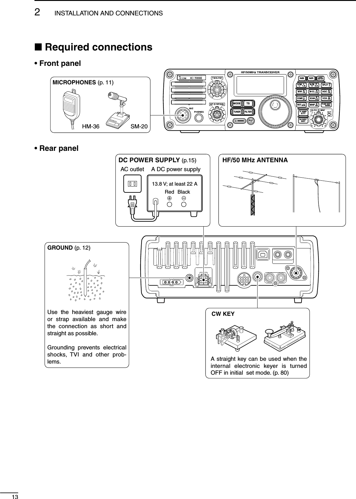
![142INSTALLATION AND CONNECTIONS123456789101112131415161718192021N Advanced connections• Front paneli7200MODETUNERTSFILTERSPCHV/MA/BSPLITM-CLSCANSETATTP.AMPCOMPVOXMNFRIT123456780502818141021 24=73.51.8F-INPM-CH/RITENTBANDGENE9.AGCMWANFMETERNRNBHEADPHONESMICThe AFSK modulation signal can be input from [MIC]. (p. 19)• Rear panelACC SOCKET (p. 10)AH-4 (p. 16) AH-2b or long wirewithEXTERNALSPEAKER (p. 91)SP-21REMOTE (p. 87)Used for computer control and transceive operation.[SEND], [ALC] (p. 17)Used for connecting a non-Icom linear amplifier.](https://usermanual.wiki/ICOM-orporated/301500/User-Guide-977157-Page-19.png)
![16123456789101112131415161718192021N External antenna tunersCONNECTING THE AH-4GroundGroundLong wire or optional AH-2bAH-4[ANT]IC-7200Coaxial cable(from the AH-4)[TUNER]CONNECTING THE AT-180IC-7200GroundAT-180HFto 6 mantenna[TRANSCEIVER][ANT][ANT][ACC] [ACC]ACC cable supplied with the AT-180Coaxial cable suppliedwith the AT-180Either of the two external connectorsGround• Turn the IC-7200’s power OFF when connecting the AT-180, otherwise, the CPU may malfunction and the AT-180 may not function properly.2INSTALLATION AND CONNECTIONS](https://usermanual.wiki/ICOM-orporated/301500/User-Guide-977157-Page-21.png)
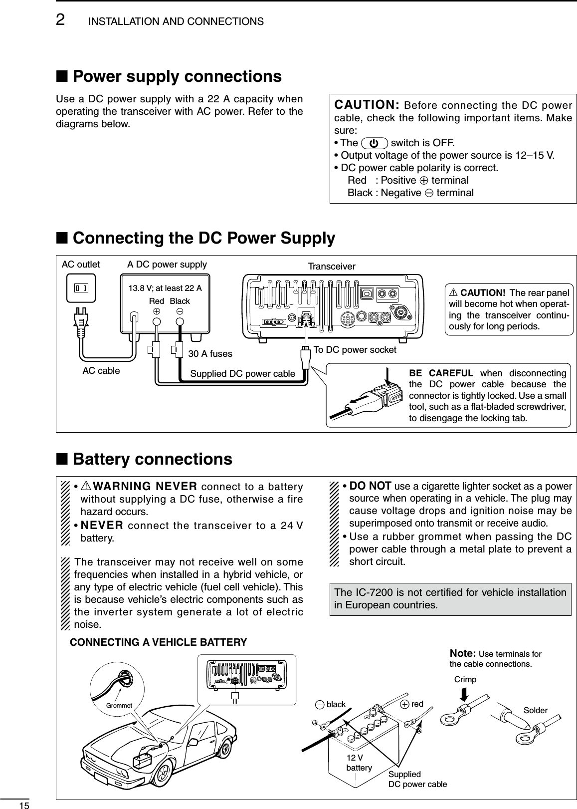
![17CONNECTING THE IC-PW1/EUROTo anantenna [ACC-1][ANT][ACC][INPUT1][REMOTE]EXCITER11&2[GND][GND]IC-PW1/EUROTo AC outlet Non-European versions : 100–120/220–240 V European version : 230 VGroundTransceiver[REMOTE]Remote control cable (supplied with the IC-PW1/EURO)ACC cable (supplied with the IC-PW1/EURO)Coaxial cable(supplied with the IC-PW1/EURO)7-pin sideOPC-599 conversion cable()[ANT]N Linear amplifier connectionsCONNECTING A NON-ICOM LINEAR AMPLIFIERR WARNING:• Set the transceiver output power and linear am-plifier ALC output level by referring to the linear amplifier instruction manual. Be sure the linear amplifier keying circuit control voltage is compat-ible with the IC-7200, before connecting to the [SEND] connector.• The ALC input level must be in the range +0 V to –4 V, and the transceiver does not accept posi-tive voltage. Non-matched ALC and RF power settings could cause a fire or damage the linear amplifier.The IC-7200 SEND line is rated at 16 V/200 mA DC. If this level is exceeded, a larger external relay must be used.Transceiver50 ø coaxial cableRF OUTPUT RF INPUTALCSEND[ANT][ALC][SEND]To an antennaNon-Icom linear amplifier2INSTALLATION AND CONNECTIONS](https://usermanual.wiki/ICOM-orporated/301500/User-Guide-977157-Page-22.png)
![18123456789101112131415161718192021NConnections for CWRear panelPaddleKEYMICStraight keyMicrophone (HM-36)Set mode settings (p. 80)4812ACC123765910 1113For no break-in operation:Connect an external switch such as a foot switch; or use the RTTY SEND terminal for all bands. (See p. 19)See p. 82 for connection details: Paddle operation from the [MIC] connector.BugReverseNormalMic Up/Down keyer: ONKeyer type: Straight-keyKeyer type: Bug-keyPaddle polarity: ReversePaddle polarity: Normal2INSTALLATION AND CONNECTIONS](https://usermanual.wiki/ICOM-orporated/301500/User-Guide-977157-Page-23.png)
![192INSTALLATION AND CONNECTIONSNConnections for RTTYD Connections for RTTY (FSK)[ACC]Rear panel4812123765910 1113(Rear panel view)PC*Connect SQL line when required.SQL* (light green)FSKK (black)AF out (light blue)HSEND (orange)GND (red)TNC or PC interface for the RTTY softwareColors refer to the wires in the supplied ACC cable.D Connections for RTTY (AFSK)[MIC]Front paneli AF outPC*Connect SQL line when required.TNC or PC interface for the RTTY softwarer SQL* t PTTy GND u GNDq MIC(Front panel view)](https://usermanual.wiki/ICOM-orporated/301500/User-Guide-977157-Page-24.png)
![202INSTALLATION AND CONNECTIONS123456789101112131415161718192021NConnections for SSTV or PSK31D When connecting to the [ACC] socket[ACC]Rear panel4812123765910 1113*Connect SQL line when required.SQL* (light green)AF in (pink)AF out (light blue)HSEND (orange)GND (red)PCTNC or PC interface for the softwareColors refer to the wires in the supplied ACC cable.(Rear panel view)D When connecting to the [MIC] connector[MIC]Front paneli AF outPC*Connect SQL line when required.TNC or PC interface for the softwarer SQL* t PTTy GND u GNDq MIC(Front panel view)](https://usermanual.wiki/ICOM-orporated/301500/User-Guide-977157-Page-25.png)
![N When first applying power (CPU resetting)N Initial settingsAfter resetting the transceiver, set controls and switches as shown in the figure below.i7200MODETUNERTSFILTERSPCHV/MA/BSPLITM-CLSCANSETATTP.AMPCOMPVOXMNFRIT123456780502818141021 24=73.51.8F-INPM-CH/RITENTBANDGENE9.AGCMWANFMETERNRNB[TWIN PBT]: Center* CCW: counterclockwise [POWER]: OFF[RF/SQL]: Center[AF]: Max. CCW*Before first applying power, make sure all connec-tions required for your system are complete by refer-ring to Chapter 2. Then, reset the transceiver using the following procedure.Resetting CLEARS all programmed contents in memory channels and returns the quick set mode/set mode to default values.q Make sure the transceiver power is OFF.w While pushing and holding F-INP ENTBAND and M-CL , push to turn power ON. • The internal CPU is reset. • The transceiver displays its initial VFO frequencies when resetting is complete.e All quick set mode/set mode settings are returned to default values. (p. 70)MODETUNERTSFILTERSPCHV/MA/BSPLITM-CLSCANSETATTP.AMPCOMPVOXMNFRIT123456780502818141021 24=73.51.8F-INPM-CH/RITENTBANDGENE9.AGCMWANFMETERNRNBM-CL514F-INP ENTBANDUnder cooler temperatures, the LCD may appear dark and unstable after turning power ON. This is normal and does not indicate any equipment mal-function.321BASIC OPERATIONTurn power ON, then check the display. If any of the following indicators appear, turn them OFF as follows:• Lock indicator, “ ” : Push and hold SPCH for 1 sec.• Tuning step indicator, “√” : Push TS .• 1 Hz frequency readout : Push and hold TS for 1 sec.• Preamp indicator, “ ” : Push P.AMPATT .• Attenuator indicator, “ ” : Push P.AMPATT .• Noise blanker indicator, “ ” : Push NB .• Noise reduction indicator, “ ” : Push NR .• Manual notch indicator, “ ” : Push MNF .• Auto notch indicator, “ ” : Push ANFMETER .• Memory mode indicator, “ ” : Push V/M• Split indicator, “ ” : Push SPLIT .](https://usermanual.wiki/ICOM-orporated/301500/User-Guide-977157-Page-26.png)
![223BASIC OPERATION123456789101112131415161718192021N VFO descriptionVFO is an abbreviation of Variable Frequency Oscilla-tor, and traditionally refers to an oscillator.The IC-7200 VFO can store a frequency and an oper-ating mode.You can call up a desired frequency to the VFO with the keypad or the memory copy function (see p. 63). You can also change the frequency with [DIAL] and select an operating mode with MODE or call up previ-ously accessed frequency and modes with the band stacking register (p. 24).The IC-7200 has two VFOs, specially suited for split frequency operation. The VFOs are called VFO A and VFO B. You can use the desired VFO to call up a fre-quency and operating mode for operation.SelectMEMORYCHANNELDIAL7.001 MHz21.295 MHzBANDChangeTransferTransferVFON VFO operationD Selecting the VFO A/BD VFO equalization± Push A/B= to toggle VFO A or VFO B.MODETUNERTSFILTERSPCHV/MA/BSPLITM-CLSCANSETATTP.AMPCOMPVOXMNFRIT123456780502818141021 24=73.51.8F-INPM-CH/RITENTBANDGENE9.AGCMWANFMETERNRNBEither “ ” or“ ” appears.± Push and hold A/B= for 1 sec. to set the undis-played VFO frequency and mode to the displayed VFO frequency • 3 beeps sound when the VFO equalization is completed.CONVENIENTUse two VFOs as a quick memoryWhen you find a new station, but you wish to con-tinue searching, the two VFO system can be used for quick memory storage.q Push and hold A/B= for 1 sec. to store the dis-played frequency into the undisplayed VFO.w Continue searching for stations.e Push A/B= to retrieve the stored frequency.r To continue searching for a station, push A/B= again.Push and holdfor 1 sec.,then push again.](https://usermanual.wiki/ICOM-orporated/301500/User-Guide-977157-Page-27.png)
![233BASIC OPERATIONN Selecting VFO/memory mode± Push V/M to toggle between VFO and memory modes.MODETUNERTSFILTERSPCHV/MA/BSPLITM-CLSCANSETATTP.AMPCOMPVOXMNFRIT123456780502818141021 24=73.51.8F-INPM-CH/RITENTBANDGENE9.AGCMWANFMETERNRNBD Differences between VFO mode and memory modeVFO MODEEach VFO shows a frequency and operating mode. If the frequency or operating mode is changed, the VFO automatically memorizes the new frequency or operating mode.When the VFO is selected from another VFO or memory mode, the last used frequency and operat-ing mode for that VFO appears.[EXAMPLE]Changed frequency (14.123 MHz) does not appear and memorized frequency (14.100 MHz) appears instead.Memory channel 1is selected.The frequency ischanged.Memory channel 1 is selected again.Another memory channel is selected.VFO is selected.The frequency ischanged.VFO is selectedagain.Changed frequency (14.123 MHz) appears.Memory mode isselected.MEMORY MODE (pgs. 61–64)Each memory channel shows a frequency and op-erating mode like a VFO. Even if the frequency or mode is changed, the memory channel does not memorize the new frequency or operating mode.When the memory channel is selected from another memory channel or VFO mode, the memorized frequency and operating mode appear even if the memory channel settings, frequency and mode, are changed before selecting another memory channel or VFO mode.[EXAMPLE]](https://usermanual.wiki/ICOM-orporated/301500/User-Guide-977157-Page-28.png)
![243BASIC OPERATION123456789101112131415161718192021N Selecting an operating bandThe transceiver has a band stacking register. This function automatically memorizes the last operating frequency and mode used on a particular band.This is convenient for contest operation.See the table below for a list of the bands availa-ble and the default settings for each register. And to send or read the desired band stacking register’s con-tents, a combination of the frequency band and reg-ister codes as follows are used with the CI-V system. (p. 88)For example, when sending/reading the oldest con-tents in the 21 MHz band, the code “07” is used.BAND REGISTER CODE FREQUENCY RANGE 1.8 MHz 1.900000 MHz CW 01 1.800000 – 1.999999 3.5 MHz 3.550000 MHz LSB 02 3.400000 – 4.099999 7 MHz 7.050000 MHz LSB 03 6.900000 – 7.499999 10 MHz 10.120000 MHz CW 04 9.900000 – 10.499999 14 MHz 14.100000 MHz USB 05 13.900000 – 14.499999 18 MHz 18.100000 MHz USB 06 17.900000 – 18.499999 21 MHz 21.200000 MHz USB 07 20.900000 – 21.499999 24 MHz 24.950000 MHz USB 08 24.400000 – 25.099999 28 MHz 28.500000 MHz USB 09 28.000000 – 29.999999 50 MHz 50.100000 MHz USB 10 50.000000 – 54.000000General 15.000000 MHz USB 11 Other than aboveD Using the band stacking registerq Push and hold F-INP ENTBAND for 1 sec. to enter the band selection mode.w Push 514 to select 14 MHz band. • The last operated frequency and mode are memo-rized.e Push MODE to select an operating mode; rotate [DIAL] to select an operating frequency.V/MA/BSPLITM-CLSCANCOMPVOXMNFRIT123456780502818141021 24=73.51.8F-INP ENTBANDGENE9.AGCMW[Example]: 14 MHz bandMODETUNERTSFILTERSPCHV/MA/BSPLITM-CLSCANSETATTP.AMPCOMPVOXMNFRIT123456780502818141021 24=73.51.8F-INPM-CH/RITENTBANDGENE9.AGCMWANFMETERNRNBBand keys](https://usermanual.wiki/ICOM-orporated/301500/User-Guide-977157-Page-29.png)
![25N Frequency settingThe transceiver has several tuning methods for con-venient frequency tuning.D Using the main dialq After pushing and holding F-INP ENTBAND for 1 sec., push the desired band key to select the corresponding band. • When you push •GENE , the general coverage receiver band is selected.w Rotate [DIAL] to set the desired frequency. If the dial lock function is activated, “ ” (lock in-dicator) appears, and [DIAL] does not function.± Push and hold SPCH for 1 sec. to deactivate the lock function. (see p. 29 for details)MODETUNERTSFILTERSPCHV/MA/BSPLITM-CLSCANSETATTP.AMPCOMPVOXMNFRIT123456780502818141021 24=73.51.8F-INPM-CH/RITENTBANDGENE9.AGCMWANFMETERNRNBBand keys[DIAL]D Direct frequency entry with keypadThe transceiver has a keypad for direct frequency entry as described at right.q Push F-INP ENTBAND .w Input the desired frequency with the numeral keys on the keypad. • Push •GENE to input “• (decimal point)” between the MHz digits and kHz digits.e Push F-INP ENTBAND to set the input frequency. • To cancel the input, push M-CH/RITSET (or any key except keypad).• 21.280 MHz 21.245 MHz• 14.025 MHz[EXAMPLE]• 706 kHzF-INP ENTBANDF-INP ENTBANDRITGENE.F-INP ENTBANDF-INP ENTBAND410MWV/M11.8RITGENE.MNF050M-CL514A/B2=3.5F-INP ENTBANDMNF050RITGENE.MNF050COMP721618AGCM-CL514A/B2=3.5410MWF-INP ENTBAND3BASIC OPERATION](https://usermanual.wiki/ICOM-orporated/301500/User-Guide-977157-Page-30.png)
![26123456789101112131415161718192021D Programmable tuning stepsD Selecting the programmable tuning stepProgrammable tuning steps are available to suit your operating requirements.These tuning steps are: • Selectable from 0.1, 1, 5, 9 and 10 kHzMODETUNERTSFILTERSPCHV/MA/BSPLITM-CLSCANSETATTP.AMPCOMPVOXMNFRIT123456780502818141021 24=73.51.8F-INPM-CH/RITENTBANDGENE9.AGCMWANFMETERNRNB[DIAL]q Push TS to turn the programmable tuning func-tion ON. • “Z” appears.Programmable tuning step indicatorw Push and hold TS for 1 sec. to enter the tuning step set mode.e Rotate [DIAL] to select the desired tuning step from 0.1, 1, 5, 9 or 10 kHz.r Push TS to exit the tuning step set mode.t Rotate [DIAL] to change the frequency according to the set tuning step.y Push TS to turn the programmable tuning func-tion OFF. • “Z” disappears.The operating frequency can be changed in steps of (0.1, 1, 5, 9 or 10 kHz selectable) for quick tuning.MODETUNERTSFILTERSPCHV/MA/BSPLITM-CLSCANSETATTP.AMPCOMPVOXMNFRIT123456780502818141021 24=73.51.8F-INPM-CH/RITENTBANDGENE9.AGCMWANFMETERNRNB[DIAL]q Push TS to turn the programmable tuning func-tion ON. • “Z” appears.Programmable tuning step indicatorw Rotate [DIAL] to change the frequency in pro-grammed kHz steps.e Push TS again to turn the programmable tuning function OFF. • “Z” disappears.r Rotate [DIAL] for normal tuning, if desired.3BASIC OPERATION](https://usermanual.wiki/ICOM-orporated/301500/User-Guide-977157-Page-31.png)
![27D 1 Hz and 10 Hz tuning stepsWhen the programmable tuning step “Z” disappears, rotating [DIAL] changes the frequency in increments of 1 or 10 Hz.MODETUNERTSFILTERSPCHV/MA/BSPLITM-CLSCANSETATTP.AMPCOMPVOXMNFRIT123456780502818141021 24=73.51.8F-INPM-CH/RITENTBANDGENE9.AGCMWANFMETERNRNB[DIAL] NOTE: The frequency is changed in 50 Hz step when the [UP]/[DN] switches of the microphone are used for the frequency setting even if the 1 Hz tuning is selected.± Push and hold TS for 1 sec. to toggle between the 1 Hz and 10 Hz step settings. • When the 1 Hz step is selected, the 1 Hz digit appears in the frequency indication; when the 10 Hz step is selected, the 1 Hz digit disappears from the frequency indication. • Rotating [DIAL] changes the frequency in 1 Hz or 10Hz tuning step.Push and holdfor 1 sec.Rotating [DIAL] changes thefrequency in 10 Hz steps.Rotating [DIAL] changes thefrequency in 1 Hz steps.TSAppears10 Hz tuning1 Hz tuningD TS switch flow chart1 Hz tuning10 Hz tuning Programmable step tuning(0.1 kHz –10 kHz)Tuning step set modemomentarily1 sec.1 sec.1 sec.Push and holdPushmomentarilyPushTSAppearsProgrammable tuning step indicator3BASIC OPERATION](https://usermanual.wiki/ICOM-orporated/301500/User-Guide-977157-Page-32.png)
![28123456789101112131415161718192021D Auto tuning step functionWhen rotating the tuning dial rapidly, the tuning speed accelerates automatically as selected.[DIAL]MODETUNERTSFILTERSPCHV/MA/BSPLITM-CLSCANSETATTP.AMPCOMPVOXMNFRIT123456780502818141021 24=73.51.8F-INPM-CH/RITENTBANDGENE9.AGCMWANFMETERNRNB[M-CH]q Push and hold M-CH/RITSET for 1 sec. twice to enter the set mode.w Rotate [M-CH] to select “AUTo TS.”e Rotate [DIAL] to select the desired tuning speed from HI (High), Lo (Low) and oF (OFF). • HI : Approx. 5 times faster when the tuning step is set to 1 kHz or smaller steps; approx. 2 times faster when the tuning step is set to 5 kHz or larger steps. • Lo : Approx. 2 times faster • oF : Auto tuning step is turned OFF • Push and hold M-CL for 1 sec. to select a default con-dition or value.When “HI” is selected (default)r Push M-CH/RITSET to exit the set mode and return to normal operation.D ¼ tuning function (SSB data/AM data/CW/RTTY only)While operating in SSB data/AM data/CW/RTTY, the ¼ tuning function is available for critical tuning. Dial sensitivity is reduced to ¼ of normal when the ¼ function is in use.[DIAL]MODETUNERTSFILTERSPCHV/MA/BSPLITM-CLSCANSETATTP.AMPCOMPVOXMNFRIT123456780502818141021 24=73.51.8F-INPM-CH/RITENTBANDGENE9.AGCMWANFMETERNRNB[M-CH]q Push and hold M-CH/RITSET for 1 sec. twice to enter the set mode.w Rotate [M-CH] to select “DIAL ¼.”e Rotate [DIAL] to select the ¼ tuning function ON and OFF. • Push and hold M-CL for 1 sec. to select a default con-dition or value.When “OFF” is selected (default)r Push M-CH/RITSET to exit the set mode and return to normal operation. NOTE: This function is only available when the programmable tuning step is OFF (p. 26).D Band edge warning beepWhen selecting a frequency that lies outside of a band’s specified frequency range, a warning beep sounds.This function can be turned OFF in set mode, if de-sired.[DIAL]MODETUNERTSFILTERSPCHV/MA/BSPLITM-CLSCANSETATTP.AMPCOMPVOXMNFRIT123456780502818141021 24=73.51.8F-INPM-CH/RITENTBANDGENE9.AGCMWANFMETERNRNB[M-CH]q Push and hold M-CH/RITSET for 1 sec. twice to enter the set mode.w Rotate [M-CH] to select “BAND BEP.”e Rotate [DIAL] to select the band edge warning beep function ON and OFF. • Push and hold M-CL for 1 sec. to select a default con-dition or value.When “ON” is selected (default)r Push M-CH/RITSET to exit the set mode and return to normal operation.3BASIC OPERATION](https://usermanual.wiki/ICOM-orporated/301500/User-Guide-977157-Page-33.png)
![29N Volume settingRotate the [AF] control clockwise to increase; coun-terclockwise to decrease the audio output level.• Set a suitable audio level.MODETUNERTSFILTERSPCHV/MA/BSPLITM-CLSCANSETATTP.AMPCOMPVOXMNFRIT123456780502818141021 24=73.51.8F-INPM-CH/RITENTBANDGENE9.AGCMWANFMETERNRNB[AF]Audio outputdecreasesAudio outputincreasesN Operating mode selectionThe following modes are available in the IC-7200:SSB (USB/LSB), SSB data (USB data/LSB data), CW, CW-R (CW Reverse), RTTY, RTTY-R (RTTY Re-verse), AM and AM data modesMODETUNERTSFILTERSPCHV/MA/BSPLITM-CLSCANSETATTP.AMPCOMPVOXMNFRIT123456780502818141021 24=73.51.8F-INPM-CH/RITENTBANDGENE9.AGCMWANFMETERNRNBOPERATING MODE SELECTIONPush and holdfor 1 sec.MODEUSB LSBAMCW CW-RRTTY-RRTTYPushmomentarilyMODE± Push MODE one or more times to select desired operation mode.± Push and hold MODE for 1 sec. to toggle between USB and LSB. (SSB mode only)± Push and hold MODE for 1 sec. to toggle be-tween CW and CW Reverse or RTTY and RTTY Reverse. (CW and RTTY mode only)± SSB data (USB data/LSB data) or AM data mode can be selected in the set mode (p. 71) • The selected mode is indicated in the function display. NOTE: If a desired operating mode cannot be se-lected, it may be disabled in the set mode (p. 81).N Dial lock functionThe dial lock function prevents accidental changes caused by [DIAL].MODETUNERTSFILTERSPCHV/MA/BSPLITM-CLSCANSETATTP.AMPCOMPVOXMNFRIT123456780502818141021 24=73.51.8F-INPM-CH/RITENTBANDGENE9.AGCMWANFMETERNRNB±Push and hold SPCH for 1 sec. to turn the dial lock function ON and OFF. • “ ” appears while the dial lock function is activated.Appears3BASIC OPERATION](https://usermanual.wiki/ICOM-orporated/301500/User-Guide-977157-Page-34.png)
![303BASIC OPERATION123456789101112131415161718192021N RF gain and SquelchN Meter functionThe [RF/SQL] control adjusts the RF gain and squelch threshold level. The squelch stops noise out-put from the speaker (closed position) when no sig-nal is received.• The 12 o’clock position is recommended for any setting of the [RF/SQL] control.• The [RF/SQL] control can be set as the RF gain control only (squelch is fixed open) or squelch control (RF gain is fixed at maximum) in the set mode (p. 75). See the table as below.MODE SET MODE SETTINGAUTO SQL RF + SQLSSB, CWRTTY RF GAIN SQL RF GAIN + SQLAM SQL SQL RF GAIN + SQLM Adjusting RF gain (Receive sensitivity)Normally, the [RF/SQL] control is set to the 12 o’clock position.Rotate the [RF/SQL] control to the 11 o’clock posi-tion for maximum sensitivity.• Rotate the [RF/SQL] control clockwise to increase, coun-terclockwise to decrease the receiver sensitivity.• The S-meter indicates receive sensitivity.M Adjusting squelch (Removing non-signal noise)Rotate the [RF/SQL] control clockwise until the noise just disappears when no signal is being received.• “ ” disappears.• Rotate the [RF/SQL] control past the threshold point in-vokes the S-meter squelch— this allows you to set the minimum signal level needed to open the squelch.• A segment appears in the S-meter to indicate the S-me-ter squelch level.MODETUNERTSFILTERSPCHV/MA/BSPLITM-CLSCANSETATTP.AMPCOMPVOXMNFRIT123456780502818141021 24=73.51.8F-INPM-CH/RITENTBANDGENE9.AGCMWANFMETERNRNB[RF/SQL]Minimum RF gainAdjustable rangeRF gain adjustablerangeMaximum RF gainMaximum RF gainSquelch is open. S-meter squelchS-meter squelchthresholdSquelch is open.S-meter squelchS-meter squelchthreshold• When functioning as RF GAIN/SQL control• When functioning as RF GAIN control• When functioning as SQL controlLowest Threshold Highest ThresholdThe transceiver has 3 transmit meter functions for your convenience. Select the desired meter from RF power (Po), ALC and SWR.MODETUNERTSFILTERSPCHV/MA/BSPLITM-CLSCANSETATTP.AMPCOMPVOXMNFRIT123456780502818141021 24=73.51.8F-INPM-CH/RITENTBANDGENE9.AGCMWANFMETERNRNB± Push and hold ANFMETER for 1 sec. to toggle between RF power (Po), SWR and ALC. • The display indication changes as the following table.DISPLAYINDICATION MEASUREMENTPo Indicates the relative RF output power. SWRIndicates the SWR on the transmission line.ALCIndicates the ALC level. When the meter movement shows the input signal level exceeds the allowable level, the ALC lim-its the RF power. In such cases, reduce the MIC gain setting (see p. 31) in the quick set mode.](https://usermanual.wiki/ICOM-orporated/301500/User-Guide-977157-Page-35.png)
![31N Basic transmit operationBefore transmitting, monitor your selected oper-ating frequency to make sure transmitting won’t cause interference to other stations on the same frequency.It’s good Amateur practice to listen first. On the HF bands, even if nothing is heard, ask “is the frequency in use” once or twice, before you begin operating on that frequency.D Transmittingq Push [PTT] (microphone) to transmit. • “ ” appears.w Release [PTT] (microphone) to return to receive. • “ ” disappears.Appears while transmittingD Output power and Microphone gain settingsIf a linear amplifier is connected such as the IC-PW1/EURO, set the output power using the ALC meter (see at “Microphone gain setting” as below) to the ALC zone (ALC meter reading should be within this zone), otherwise the linear amplifier will not work properly.M Output power settingq Push and hold M-CH/RITSET for 1 sec. to enter the quick set mode.w Rotate [M-CH] to select “RF POWER.”e Rotate [DIAL] to select the desired output setting. • Output power is displayed in 101 steps (Low, 1–100.)r Push M-CH/RITSET to exit the quick set mode and re-turn to normal operation.• Available power SSB/CW/RTTY : 2–100 W AM : 1–25 W* (*Carrier power)M Microphone gain settingMicrophone gain must be adjusted properly so that your signal does not distort when transmitted.q Select SSB or AM mode.w Push and hold ANFMETER for 1 sec. several times to select the ALC meter.e Push and hold M-CH/RITSET for 1 sec. to enter the quick set mode.r Rotate [M-CH] to select “MIC GAIN.”t Push [PTT] (microphone) to transmit. • Speak into the microphone at your normal voice level.y While speaking into the microphone, rotate [DIAL] so that the ALC meter reading does not go out-side the ALC zone. • Microphone gain is adjusted in 1% steps (0% to 100%).u Release [PTT] (microphone) to return to receive.i Push M-CH/RITSET to exit the quick set mode and re-turn to normal operation.MODETUNERTSFILTERSPCHV/MA/BSPLITM-CLSCANSETATTP.AMPCOMPVOXMNFRIT123456780502818141021 24=73.51.8F-INPM-CH/RITENTBANDGENE9.AGCMWANFMETERNRNB[M-CH][DIAL]When maximum output power“100” is selected (default)When “50” is selected (default)ALC zone3BASIC OPERATION](https://usermanual.wiki/ICOM-orporated/301500/User-Guide-977157-Page-36.png)
![433RECEIVE AND TRANSMITN Operating SSBq Push and hold F-INP ENTBAND for 1 sec., then push a band key to select the desired band.w Push MODE to select SSB mode. • After SSB mode is selected, push and hold MODE for 1 sec. to toggle between LSB and USB modes. • Below 10 MHz LSB is automatically selected; above 10 MHz USB is automatically selected.e Rotate [DIAL] to tune in a desired signal. • The S-meter indicates received signal strength when a signal is received.r Rotate the [AF] control to set audio to a comfort-able listening level.t Push [PTT] (microphone) to transmit. • “ ” appears.y Speak into the microphone at your normal voice level. • Adjust ‘MIC Gain’ at this step, if necessary. (p. 71)u Release [PTT] (microphone) to return to receive.MODETUNERTSFILTERSPCHV/MA/BSPLITM-CLSCANSETATTP.AMPCOMPVOXMNFRIT123456780502818141021 24=73.51.8F-INPM-CH/RITENTBANDGENE9.AGCMWANFMETERNRNBBand keys[DIAL][AF]“USB” or “LSB” appears.Appears while transmitting.D Convenient functions for receive• Preamp and attenuator (p. 45)± Push P.AMPATT to turn the preamp ON or OFF. • “ ” appears when the preamp is set to ON.± Push and hold P.AMPATT for 1 sec. to turn the attenu-ator ON. • Push P.AMPATT to turn the attenuator OFF. • “” appears when the attenuator is set to ON.• Twin PBT (passband tuning) (p. 46)±Rotate [TWIN PBT] (controls–inner/outer).• AGC (auto gain control) (p. 45)± Push AGC once or twice to select the time con-stant for the AGC circuit fast and slow. • “F.AG C” appears when the fast time constant is se-lected, and no indicator appears when the slow time constant is selected, respectively.± Push and hold AGC for 1 sec. to turn the AGC function OFF. • “AGC-OFF” appears on the display.• Noise blanker (p. 49)± Push NB to turn the noise blanker ON or OFF. • “ ” appears when the noise blanker is set to ON.± Push and hold NB for 1 sec. to enter the noise blanker set mode, then rotate [DIAL] to adjust the threshold level, or the blank time. • Rotate [M-CH] to select an item.• Noise reduction (p. 50)± Push NR to turn the noise reduction ON or OFF. • “ ” appears when the noise reduction is ON.± Push and hold NR for 1 sec. to enter the noise reduction level set mode, then rotate [DIAL] to adjust the noise reduction level.• Manual notch filter (pgs. 51, 52)± Push MNF to turn the manual notch filter ON or OFF. • “ ” appears when the manual notch filter is set to ON.± Push and hold MNF for 1 sec. to enter the man-ual notch filter set mode, then rotate [DIAL] to se-lect the filter width from narrow, middle and wide.• Auto notch filter (p. 51)± Push ANFMETER to turn the auto notch filter ON or OFF. • “” appears when the auto notch filter is set to ON.](https://usermanual.wiki/ICOM-orporated/301500/User-Guide-977157-Page-38.png)
![344RECEIVE AND TRANSMIT123456789101112131415161718192021D Convenient functions for transmit• VOX (voice operated transmit) (p. 53)± Push VOX to turn the VOX function ON or OFF. • “ ” appears when the VOX function is ON.± Push and hold VOX for 1 sec. to enter the VOX set mode, then rotate [DIAL] to adjust the VOX gain, anti VOX gain or VOX delay. • Rotate [M-CH] to select an item.• Speech compressor (p. 57)± Push COMP to turn the speech compressor ON or OFF. • “” appears when the speech compressor is ON.± Push and hold COMP for 1 sec. to enter the com-pression level set mode, then rotate [DIAL] to ad-just the compression level.D About 5 MHz band operation (USA version only)Operation on the 5 MHz band is allowed on 5 dis-crete frequencies and must adhere to the following:• USB mode• Maximum of 50 watts ERP (Effective Radiated Power)• 2.8 kHz bandwidthIt is the operator’s responsibility to set all controls so that the transmission in this band meets the stringent conditions under which we may use these frequen-cies. NOTE: We recommend that you store these fre-quencies, mode and filter settings into the mem-ory channel for easy recall.IC-7200 Display Frequency*FCC Channel Center Frequency*5.33050 MHz 5.33200 MHz5.34650 MHz 5.34800 MHz5.36650 MHz 5.36800 MHz5.37150 MHz 5.37300 MHz5.40350 MHz 5.40500 MHz* The channel center frequencies that are specified by the FCC, show the center frequency of their passband. However, the IC-7200 displays carrier point frequency, so set 1.5 kHz below from FCC channel center frequency.To assist you in operating the 5 MHz band cor-rectly within the rules specified by the FCC, transmission is impossible on any 5 MHz band frequency other than the 5 frequencies indicated in the table above.](https://usermanual.wiki/ICOM-orporated/301500/User-Guide-977157-Page-39.png)
![35N Operating CWq Connect a paddle or straight key as on page 18.w Push and hold F-INP ENTBAND for 1 sec., then push a band key to select the desired band.e Push MODE to select CW mode. • After CW mode is selected, push and hold MODE for 1 sec. to toggle between CW and CW-R modes.r Rotate [DIAL] to tune in a desired signal with the desired tone frequency. • The S-meter indicates received signal strength when signal is received.t Rotate the [AF] control to set audio to a comfort-able listening level.y Set CW break-in operation and the CW delay time in the set mode. (p. 79)q Push and hold M-CH/RITSET for 1 sec. twice to enter the set mode.w Rotate [M-CH] to select “BK-IN” to set the CW break-in operation.e Rotate [DIAL] to select the CW break-in opera-tion from full break-in, semi break-in or OFF. • FL : full break-in • SE : semi break-in • OF : break-in OFFr Rotate [M-CH] to select “BK-DELAY” to select the CW delay time when semi break-in operation is selected in step e.t Rotate [DIAL] to set the desired delay time.u Continue to set the keyer settings in the set mode, if necessary. (p. 80)i Push M-CH/RITSET to exit the set mode and return to normal operation.o Keying to transmit, use the electric keyer, paddle or straight key to send your CW signals. • “ ” appears. • The Po meter indicates transmitted CW signal strength.!0 Stop keying to return to receive.MODETUNERTSFILTERSPCHV/MA/BSPLITM-CLSCANSETATTP.AMPCOMPVOXMNFRIT123456780502818141021 24=73.51.8F-INPM-CH/RITENTBANDGENE9.AGCMWANFMETERNRNBBand keys[DIAL][AF]“CW” or “CW-R” appears.Appears while transmitting.[M-CH]Appears when semi break-in is selected.4RECEIVE AND TRANSMIT](https://usermanual.wiki/ICOM-orporated/301500/User-Guide-977157-Page-40.png)
![364RECEIVE AND TRANSMIT123456789101112131415161718192021D Convenient functions for receive• Preamp and attenuator (p. 45)± Push P.AMPATT to turn the preamp ON or OFF. • “ ” appears when the preamp is set to ON.± Push and hold P.AMPATT for 1 sec. to turn the attenu-ator ON. • Push P.AMPATT to turn the attenuator OFF. • “” appears when the attenuator is set to ON.• Twin PBT (passband tuning) (p. 46)±Rotate [TWIN PBT] (controls–inner/outer).• AGC (auto gain control) (p. 45)± Push AGC once or twice to select the time con-stant for the AGC circuit fast and slow. • “F.AG C” appears when the fast time constant is se-lected, and no indicator appears when the slow time constant is selected, respectively.± Push and hold AGC for 1 sec. to turn the AGC function OFF. • “AGC-OFF” appears on the display.• Noise blanker (p. 49)± Push NB to turn the noise blanker ON or OFF. • “ ” appears when the noise blanker is set to ON.± Push and hold NB for 1 sec. to enter the noise blanker set mode, then rotate [DIAL] to adjust the threshold level, or the blank time. • Rotate [M-CH] to select an item.• Noise reduction (p. 50)± Push NR to turn the noise reduction ON or OFF. • “ ” appears when the noise reduction is ON.± Push and hold NR for 1 sec. to enter the noise reduction level set mode, then rotate [DIAL] to adjust the noise reduction level.• Manual notch filter (pgs. 51, 52)± Push MNF to turn the manual notch filter ON or OFF. • “ ” appears when the manual notch filter is set to ON.± Push and hold MNF for 1 sec. to enter the man-ual notch filter set mode, then rotate [DIAL] to se-lect the filter width from narrow, middle and wide.• ¼ function (p. 78)q Push and hold M-CH/RITSET for 1 sec. twice to enter the set mode.w Rotate [M-CH] to select “DIAL ¼”.e Rotate [DIAL] to turn the 1⁄4 function ON or OFF.r Push M-CH/RITSET to exit the set mode and return to normal operation.• CW pitch control (p. 37)q Push and hold M-CH/RITSET for 1 sec. to enter the quick set mode.w Rotate [M-CH] to select “CW PITCH”.e Rotate [DIAL] to set the desired CW pitch from 300 to 900 Hz in 10 Hz steps.r Push M-CH/RITSET to exit the quick set mode and re-turn to normal operation.D Convenient functions for transmit• Break-in function (p. 55)q Push and hold M-CH/RITSET for 1 sec. twice to enter the set mode.w Rotate [M-CH] to select “BK-IN”.e Rotate [DIAL] to select the CW break-in operation from full break-in, semi break-in or OFF. • FL : Full break-in • SE : Semi break-in • OF : Break-in OFFr Push M-CH/RITSET to exit the set mode and return to normal operation.• Keying speed setting (p. 38)q Push and hold M-CH/RITSET for 1 sec. to enter the quick set mode.w Rotate [M-CH] to select “KEY SPD”.e Rotate [DIAL] to adjust the CW key speed from 6 to 60 wpm.r Push M-CH/RITSET to exit the quick set mode and re-turn to normal operation.](https://usermanual.wiki/ICOM-orporated/301500/User-Guide-977157-Page-41.png)
![37D CW reverse modeThe CW-R (CW Reverse) mode receives CW signals on the reverse sideband like that of LSB and USB modes.Use when interference is near the desired signal and you want to shift the tone of the interfering signal.q Push MODE several times to select CW mode.w Push and hold MODE for 1 sec. to select CW or CW-R mode. • Check the interference tone.• Receive audio tone responseCW-R mode (USB side)CW mode (LSB side)BFO600 HzDesired signalInteference Desired signal600 HzBFOInteferencePush and holdfor 1 sec.MODETUNERTSFILTERSPCHV/MA/BSPLITM-CLSCANSETATTP.AMPCOMPVOXMNFRIT123456780502818141021 24=73.51.8F-INPM-CH/RITENTBANDGENE9.AGCMWANFMETERNRNBD CW pitch controlThe received CW audio pitch and monitored CW audio pitch can be adjusted to suit your preferences (300 to 900 Hz) without changing the operating fre-quency.q When CW (CW-R) mode is selected, push and hold M-CH/RITSET for 1 sec. to enter the quick set mode.w Rotate [M-CH] to select “CW PITCH”, then rotate [DIAL] to set the desired pitch. • CW pitch is adjusted in 10 Hz steps (300 to 900 Hz).e Push M-CH/RITSET to exit the quick set mode and re-turn to normal operation.MODETUNERTSFILTERSPCHV/MA/BSPLITM-CLSCANSETATTP.AMPCOMPVOXMNFRIT123456780502818141021 24=73.51.8F-INPM-CH/RITENTBANDGENE9.AGCMWANFMETERNRNB[DIAL] [M-CH]This shows the default setting forthe CW pitch control (600 Hz).4RECEIVE AND TRANSMIT](https://usermanual.wiki/ICOM-orporated/301500/User-Guide-977157-Page-42.png)
![384RECEIVE AND TRANSMIT123456789101112131415161718192021D CW side tone functionWhen the transceiver is in receive (and the break-in function is OFF— pgs. 55, 56) you can listen to the tone of your CW signal without actually transmitting.This allows you to spot your transmit signal exactly compared to another station’s. This also convenient for CW practice.q When CW (CW-R) mode is selected, push and hold M-CH/RITSET for 1 sec. to enter the quick set mode.w Rotate [M-CH] to select “SIDE LVL”, then rotate [DIAL] to adjust the side tone level. • Side tone level is adjusted in 1% steps (0% to 100%).e Push M-CH/RITSET to exit the quick set mode and re-turn to normal operation.MODETUNERTSFILTERSPCHV/MA/BSPLITM-CLSCANSETATTP.AMPCOMPVOXMNFRIT123456780502818141021 24=73.51.8F-INPM-CH/RITENTBANDGENE9.AGCMWANFMETERNRNB[DIAL] [M-CH]D Keying speed settingThe transceiver’s internal electronic keyer speed can be adjusted from 6 to 60 wpm.q When CW (CW-R) mode is selected, push and hold M-CH/RITSET for 1 sec. to enter the quick set mode.w Rotate [M-CH] to select “KEY SPD”, then rotate [DIAL] to adjust the keying speed.e Push M-CH/RITSET to exit the quick set mode and re-turn to normal operation.MODETUNERTSFILTERSPCHV/MA/BSPLITM-CLSCANSETATTP.AMPCOMPVOXMNFRIT123456780502818141021 24=73.51.8F-INPM-CH/RITENTBANDGENE9.AGCMWANFMETERNRNB[DIAL] [M-CH]](https://usermanual.wiki/ICOM-orporated/301500/User-Guide-977157-Page-43.png)
![394RECEIVE AND TRANSMITNOperating RTTY (FSK)When using your RTTY terminal or TNC, consult the manual that comes with the RTTY terminal or TNC.q Push and hold F-INP ENTBAND for 1 sec., then push a band key to select the desired band.w Push MODE to select RTTY mode. • After RTTY mode is selected, push and hold MODE for 1 sec. to toggle between RTTY and RTTY-R modes.e Rotate [DIAL] to tune in a desired signal. • The S-meter indicates received signal strength when signal is received. • If the received signal cannot be demodulated, try se-lecting RTTY-R mode (or RTTY mode).r Transmit a SEND signal from your TNC. • “ ” appears. • The Po meter indicates the transmitted RTTY signal strength.t Use the connected PC or TNC (TU) to transmit RTTY (FSK) signals. MODETUNERTSFILTERSPCHV/MA/BSPLITM-CLSCANSETATTP.AMPCOMPVOXMNFRIT123456780502818141021 24=73.51.8F-INPM-CH/RITENTBANDGENE9.AGCMWANFMETERNRNBBand keys[DIAL]“RTTY” or “RTTY-R” appears.F-INP ENTBANDAppears while transmitting.D Convenient functions for receive• Preamp and attenuator (p. 45)± Push P.AMPATT to turn the preamp ON or OFF. • “ ” appears when the preamp is set to ON.± Push and hold P.AMPATT for 1 sec. to turn the attenu-ator ON. • Push P.AMPATT to turn the attenuator OFF. • “” appears when the attenuator is set to ON.• Twin PBT (passband tuning) (p. 46)±Rotate [TWIN PBT] (controls–inner/outer).• AGC (auto gain control) (p. 45)± Push AGC once or twice to select the time con-stant for the AGC circuit fast and slow. • “F.AG C” appears when the fast time constant is se-lected, and no indicator appears when the slow time constant is selected, respectively.± Push and hold AGC for 1 sec. to turn the AGC function OFF. • “AGC-OFF” appears on the display.• Noise blanker (p. 49)± Push NB to turn the noise blanker ON or OFF. • “ ” appears when the noise blanker is set to ON.± Push and hold NB for 1 sec. to enter the noise blanker set mode, then rotate [DIAL] to adjust the threshold level, or the blank time. • Rotate [M-CH] to select an item.• Noise reduction (p. 50)± Push NR to turn the noise reduction ON or OFF. • “ ” appears when the noise reduction is ON.± Push and hold NR for 1 sec. to enter the noise reduction level set mode, then rotate [DIAL] to adjust the noise reduction level.• Manual notch filter (pgs. 51, 52)± Push MNF to turn the manual notch filter ON or OFF. • “ ” appears when the manual notch filter is set to ON.± Push and hold MNF for 1 sec. to enter the man-ual notch filter set mode, then rotate [DIAL] to se-lect the filter width from narrow, middle and wide.• ¼ function (p. 78)q Push and hold M-CH/RITSET for 1 sec. twice to enter the set mode.w Rotate [M-CH] to select “DIAL ¼”.e Rotate [DIAL] to turn the 1⁄4 function ON or OFF.r Push M-CH/RITSET to exit the set mode and return to normal operation.](https://usermanual.wiki/ICOM-orporated/301500/User-Guide-977157-Page-44.png)
![404RECEIVE AND TRANSMIT123456789101112131415161718192021D RTTY reverse modeReceived characters are occasionally garbled when the receive signal is reversed between MARK and SPACE. This reversal can be caused by incorrect TNC connections, settings, commands, etc.To receive a reversed RTTY signal correctly, select RTTY-R (RTTY reverse) mode.q Push MODE to select RTTY mode.w After RTTY mode is selected, push and hold MODE for 1 sec. to toggle between RTTY and RTTY-R modes.MODETUNERTSFILTERSPCHV/MA/BSPLITM-CLSCANSETATTP.AMPCOMPVOXMNFRIT123456780502818141021 24=73.51.8F-INPM-CH/RITENTBANDGENE9.AGCMWANFMETERNRNBReverseNormalBFO170Hz2125Hz170Hz2125HzBFOMarkSpaceDisplayed freq.Displayed freq.MarkSpaceD Twin peak filterThe twin peak filter changes the receive frequency response by boosting two particular frequencies (2125 and 2295 Hz) for better copying of desired RTTY signals.q Push MODE to select RTTY mode. • After RTTY mode is selected, push and hold MODE for 1 sec. to toggle between RTTY and RTTY-R modes.w Push and hold M-CH/RITSET for 1 sec. to enter the quick set mode.e Rotate [M-CH] to select “TPF”, then rotate [DIAL] to select the twin peak filter function ON or OFF. • The received audio volume may become greater when the twin peak filter is turned ON.r Push M-CH/RITSET to exit the quick set mode and re-turn to normal operation.OFF (default)MODETUNERTSFILTERSPCHV/MA/BSPLITM-CLSCANSETATTP.AMPCOMPVOXMNFRIT123456780502818141021 24=73.51.8F-INPM-CH/RITENTBANDGENE9.AGCMWANFMETERNRNB[DIAL] [M-CH]](https://usermanual.wiki/ICOM-orporated/301500/User-Guide-977157-Page-45.png)
![414RECEIVE AND TRANSMITD RTTY decode set modeSet the RTTY key polarity, shift width and mark tone.q When RTTY (RTTY-R) mode is selected, push and hold M-CH/RITSET for 1 sec. to enter the quick set mode.w Rotate [M-CH] to select the desired set item.e Rotate [DIAL] to adjust the desired value or con-dition. • Push and hold M-CL for 1 sec. to return to the default value.r Push M-CH/RITSET to exit the quick set mode and re-turn to normal operation.[DIAL]MODETUNERTSFILTERSPCHV/MA/BSPLITM-CLSCANSETATTP.AMPCOMPVOXMNFRIT123456780502818141021 24=73.51.8F-INPM-CH/RITENTBANDGENE9.AGCMWANFMETERNRNB[M-CH]RTTY mark tone (RTTY mode)This item selects the RTTY mark frequency. RTTY mark frequency is switched between 1275, 1615 and 2125 Hz.2125 Hz (default)RTTY shift width (RTTY mode)This item adjusts the RTTY shift width. There are 4 selectable values: 170, 200, 425 and 850 Hz.170 Hz (default)RTTY key polarity (RTTY mode)This item selects the RTTY keying polarity. Normal or reverse keying polarity can be selected.When reverse polarity is selected, Mark and Space are reversed.n (normal) : Key open/close = Mark/Spacer (reverse) : Key open/close = Space/MarkNORMAL (default)](https://usermanual.wiki/ICOM-orporated/301500/User-Guide-977157-Page-46.png)
![424RECEIVE AND TRANSMIT123456789101112131415161718192021N Operating AMq Push and hold F-INP ENTBAND for 1 sec., then push a band key to select the desired band.w Push MODE to select AM mode.e Rotate [DIAL] to tune in a desired signal. • The S-meter indicates received signal strength when a signal is received. • The default tuning step for AM mode is 1 kHz; this can be changed using the tuning step program mode. (p. 26)r Rotate the [AF] control to set audio to a comfort-able listening level.t Push [PTT] (microphone) to transmit. • “ ” appears.y Speak into the microphone at your normal voice level. • Adjust ‘MIC Gain’ at this step, if necessary. (p. 71)u Release [PTT] (microphone) to return to receive.MODETUNERTSFILTERSPCHV/MA/BSPLITM-CLSCANSETATTP.AMPCOMPVOXMNFRIT123456780502818141021 24=73.51.8F-INPM-CH/RITENTBANDGENE9.AGCMWANFMETERNRNB[DIAL][AF]Appears while transmitting.F-INP ENTBANDBand keys“AM” appears.D Convenient functions for receive• Preamp and attenuator (p. 45)± Push P.AMPATT to turn the preamp ON or OFF. • “ ” appears when the preamp is set to ON.± Push and hold P.AMPATT for 1 sec. to turn the attenu-ator ON. • Push P.AMPATT to turn the attenuator OFF. • “” appears when the attenuator is set to ON.• AGC (auto gain control) (p. 45)± Push AGC once or twice to select the time con-stant for the AGC circuit fast and slow. • “F.AG C” appears when the fast time constant is se-lected, and no indicator appears when the slow time constant is selected, respectively.± Push and hold AGC for 1 sec. to turn the AGC function OFF. • “AGC-OFF” appears on the display.• Noise blanker (p. 49)± Push NB to turn the noise blanker ON or OFF. • “ ” appears when the noise blanker is set to ON.± Push and hold NB for 1 sec. to enter the noise blanker set mode, then rotate [DIAL] to adjust the threshold level, or the blank time. • Rotate [M-CH] to select an item.• Twin PBT (passband tuning) (p. 46)±Rotate [TWIN PBT] (controls–inner/outer).• Noise reduction (p. 50)± Push NR to turn the noise reduction ON or OFF. • “ ” appears when the noise reduction is ON.± Push and hold NR for 1 sec. to enter the noise reduction level set mode, then rotate [DIAL] to adjust the noise reduction level.• Manual notch filter (pgs. 51, 52)± Push MNF to turn the manual notch filter ON or OFF. • “ ” appears when the manual notch filter is set to ON.± Push and hold MNF for 1 sec. to enter the man-ual notch filter set mode, then rotate [DIAL] to se-lect the filter width from narrow, middle and wide.• Auto notch filter (p. 51)± Push ANFMETER to turn the auto notch filter ON or OFF. • “” appears when the auto notch filter is set to ON.D Convenient functions for transmit• VOX (voice operated transmit) (p. 53)± Push VOX to turn the VOX function ON or OFF. • “ ” appears when the VOX function is ON.± Push and hold VOX for 1 sec. to enter the VOX set mode, then rotate [DIAL] to adjust the VOX gain, anti VOX gain or VOX delay. • Rotate [M-CH] to select an item.](https://usermanual.wiki/ICOM-orporated/301500/User-Guide-977157-Page-47.png)
![434RECEIVE AND TRANSMITN Data mode (SSTV/PSK31) operationWhen operating SSTV or PSK31 with your PC soft-ware, consult the manual that is supplied with the software.q Connect a PC to the transceiver. (p. 20)w Push and hold F-INP ENTBAND for 1 sec., then push a band key to select the desired band.e Push MODE to select SSB or AM mode. • After SSB mode is selected, push and hold MODE for 1 sec. to toggle between USB and LSB modes.r Turn data mode ON in the quick set mode.q Push and hold M-CH/RITSET for 1 sec. to enter the quick set mode.w Rotate [M-CH] to select “DATA” to set the data mode.e Rotate [DIAL] to select the data mode ON or OFF. • “ ” appears when the data mode is turned ON.r Push M-CH/RITSET to exit the quick set mode and return to normal operation.t Rotate [DIAL] to tune in a desired signal and de-coded correctly. • The S-meter indicates received signal strength when a signal is received. • Also use the tuning indicator of the software. • During SSB data mode, ¼ tuning function can be used for critical tuning.y Use the PC (software) to transmit. • When operating in SSB data mode, adjust the AF output level from PC so that the ALC meter reading doesn’t go outside the ALC zone. NOTE: When the data mode is selected, the audio input from the [ACC] connector* is used for transmission instead of [MIC] connector. The speech compressor function is turned OFF for the SSB data mode transmission. * The desired connector can be selected in the set mode. (p. 77)MODETUNERTSFILTERSPCHV/MA/BSPLITM-CLSCANSETATTP.AMPCOMPVOXMNFRIT123456780502818141021 24=73.51.8F-INPM-CH/RITENTBANDGENE9.AGCMWANFMETERNRNB[DIAL] [M-CH]Data mode: ON (default: OFF)F-INP ENTBANDBand keysEither “USB” or “LSB” appears.Appears while transmitting. Appears For your informationCarrier point frequency is displayed when SSB data mode is selected.See the diagram below for the tone-pair example.• Example— LSB/LSB data modeMark freq.: 2125 HzShift freq.: 200 Hz2325 Hz200 Hz 2125 HzCarrier(Displayed frequency)](https://usermanual.wiki/ICOM-orporated/301500/User-Guide-977157-Page-48.png)
![544FUNCTIONS FOR RECEIVE123456789101112131415161718192021N RIT functionThe RIT (Receive Incremental Tuning) function com-pensates for stations transmitting off-frequency or when you prefer to listen to slightly different-sound-ing voice characteristics, etc.The function shifts the receive frequency up to ±9.999 kHz in 1 Hz steps (10 Hz steps when cancel-ling the 1 Hz step readout) without moving the trans-mit frequency.q Push RIT to turn the RIT function ON. • “ ” and the shift frequency are indicated. - The shift frequency is indicated for approx. 1 sec., then returns to the operating frequency. • The RIT control indicator lights red. - If the RIT control indicator does not light, push M-CH/RITSET . (See below for details)w Rotate the [M-CH] control to compensate for off-frequency stations. • The transmit frequency is not shifted. • The shift frequency is indicated for about 1 sec. when rotating the [M-CH] control.e To cancel the RIT function, push RIT again. • “ ” disappears. • The RIT control indicator goes out.About the [M-CH] control: The [M-CH] control selects the memory channel and also shifts the RIT frequency. Pushing M-CH/RITSET toggles the [M-CH] control as M-CH selector or RIT controller. RIT controller: RIT control indicator lights red. M-CH selector: RIT control indicator goes out.Shifting frequencydecreasesShifting frequencyincreasesRIT control indicatorlights red.MODETUNERTSFILTERSPCHV/MA/BSPLITM-CLSCANSETATTP.AMPCOMPVOXMNFRIT123456780502818141021 24=73.51.8F-INPM-CH/RITENTBANDGENE9.AGCMWANFMETERNRNB[M-CH]Appears• RIT monitor functionWhen the XFC (transmit frequency check function) is ON (p. 76), pushing and holding RIT allows you to monitor the operating frequency directly (RIT is temporarily cancelled).• Calculate functionThe shift frequency of the RIT function can be added/subtracted to the displayed frequency.When the RIT function is ON, push and hold RIT * for 1 sec.• The RIT frequency is automatically reset.* Available only when the XFC (transmit frequency check function) is turned OFF. (p. 76)](https://usermanual.wiki/ICOM-orporated/301500/User-Guide-977157-Page-49.png)
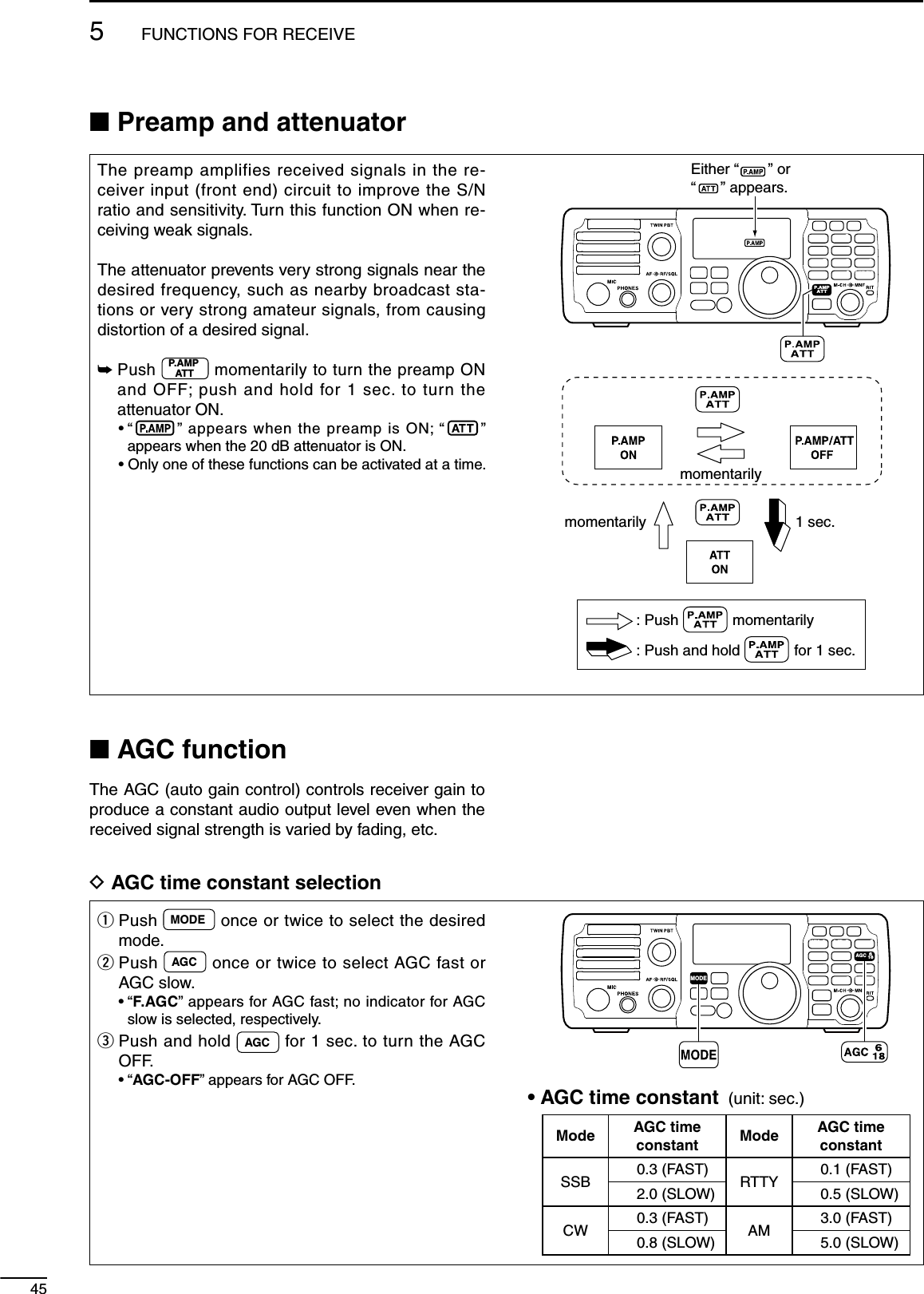
![465FUNCTIONS FOR RECEIVE123456789101112131415161718192021N Twin PBT operationThe general PBT (Passband Tuning) function elec-tronically narrows the IF passband width by shifting the IF frequency slightly outside of the IF filter pass-band to reject interference. This transceiver uses the DSP circuit for the PBT function. Moving both controls to the same position shifts the IF.The limit of the variable range depends on the pass-band width and mode. The limit of the variable range is half of the passband width, and PBT is adjustable in 25 Hz steps.MODETUNERTSFILTERSPCHV/MA/BSPLITM-CLSCANSETATTP.AMPCOMPVOXMNFRIT123456780502818141021 24=73.51.8F-INPM-CH/RITENTBANDGENE9.AGCMWANFMETERNRNB[TWIN PBT]• The [TWIN PBT] controls should normally be set to the center positions (PBT setting is cleared) when there is no interference. • When PBT is used, the audio tone may be changed. • While rotating the [TWIN PBT] control, noise may occur. This comes from the DSP unit and does not indicate an equipment malfunction.PBT OPERATION EXAMPLEIF center frequency Interference Desired signalPassbandBoth controls at center positionCutting the lower passbandCutting both higher and lower passbandsInterference InterferenceDesired signalPassbandTWIN PBTTWIN PBTTWIN PBT](https://usermanual.wiki/ICOM-orporated/301500/User-Guide-977157-Page-51.png)
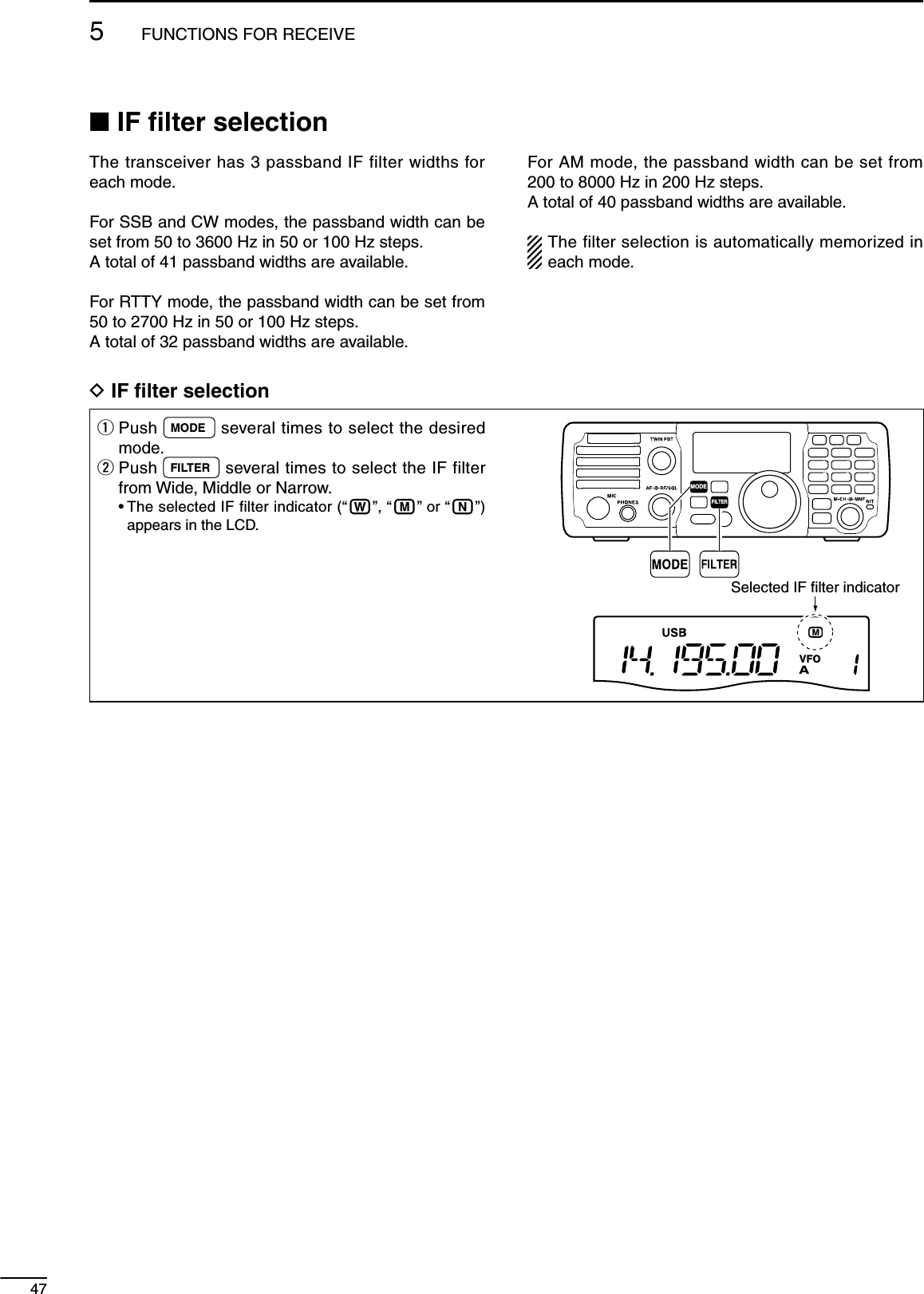
![485FUNCTIONS FOR RECEIVE123456789101112131415161718192021D FIlter passband width settingq Push MODE several times to select the desired mode.w Push and hold FILTER for 1 sec. to enter filter set mode.e Rotate [M-CH] to select “FIL.”r Push FILTER several times to select the desired IF filter.t Rotate [DIAL] to set the desired passband width. • The passband width can be set within the range as shown in the table at right below. • Push and hold M-CL for 1 sec. to return to the default value.y Repeat steps r and t if desired.u Push and hold FILTER for 1 sec. to exit the filter set mode. When the IF passband width is set to minimum by the [TWIN PBT] controls (when one control is max. counterclockwise, and the other one is max. clockwise; p. 46), a sound may not come from the speaker depending on the IF filter passband width setting. This is not a transceiver’s malfunction. MODETUNERTSFILTERSPCHV/MA/BSPLITM-CLSCANSETATTP.AMPCOMPVOXMNFRIT123456780502818141021 24=73.51.8F-INPM-CH/RITENTBANDGENE9.AGCMWANFMETERNRNB[DIAL] [M-CH]Mode Filter Default Range (Steps)SSBWide 3000 Hz50–500 Hz (50 Hz)/600–3600 Hz (100 Hz)Middle 2400 HzNarrow 1800 HzSSB Data/CWWide 1200 Hz50–500 Hz (50 Hz)/600–3600 Hz (100 Hz)Middle 500 HzNarrow 250 HzRTTYWide 2400 Hz50–500 Hz (50 Hz)/600–2700 Hz (100 Hz)Middle 500 HzNarrow 250 HzAM/AM DataWide 8000 Hz200–8000 Hz (200 Hz)Middle 6000 HzNarrow 3000 HzD IF fIlter shape (SSB/CW only)The type of DSP filter shape for SSB and CW can be selected independently from soft and sharp.q Push MODE several times to select SSB or CW mode.w Push and hold FILTER for 1 sec. to enter filter set mode.e Rotate [M-CH] to select “SHAPE.”r Push FILTER several times to select the desired IF filter from Wide, Middle or Narrow.t Rotate [DIAL] to select the desired filter shape, either soft or sharp • Push and hold M-CL for 1 sec. to return to the default value.y Push and hold FILTER for 1 sec. to exit the filter set mode.MODETUNERTSFILTERSPCHV/MA/BSPLITM-CLSCANSETATTP.AMPCOMPVOXMNFRIT123456780502818141021 24=73.51.8F-INPM-CH/RITENTBANDGENE9.AGCMWANFMETERNRNB[DIAL] [M-CH]“Sharp”“Soft”](https://usermanual.wiki/ICOM-orporated/301500/User-Guide-977157-Page-53.png)
![495FUNCTIONS FOR RECEIVEN Noise blankerThe noise blanker eliminates pulse-type noise such as from car ignition systems.± Push NB to turn the noise blanker ON or OFF. • “ ” appears when the NB function is ON. When using the noise blanker, received signals may be distorted if they are excessively strong or the noise type is other than impulse. Nearby strong signals can also cause the noise blanker to create distortion. Turn the noise blanker function OFF, or adjust the noise blanker level to a shal-lower setting (see below) in this case.MODETUNERTSFILTERSPCHV/MA/BSPLITM-CLSCANSETATTP.AMPCOMPVOXMNFRIT123456780502818141021 24=73.51.8F-INPM-CH/RITENTBANDGENE9.AGCMWANFMETERNRNBAppearsD Noise blanker settingsq Push and hold NB for 1 sec. to enter the noise blanker set mode. • The noise blanker is turned ON and “ ” appears.w Rotate [M-CH] to select the desired set item.e Rotate [DIAL] to adjust the desired condition. • Push and hold M-CL for 1 sec. to return to the default value.r Push NB to exit the noise blanker set mode.t Push NB to turn the noise blanker OFF if neces-sary. • “ ” disappears.MODETUNERTSFILTERSPCHV/MA/BSPLITM-CLSCANSETATTP.AMPCOMPVOXMNFRIT123456780502818141021 24=73.51.8F-INPM-CH/RITENTBANDGENE9.AGCMWANFMETERNRNB[DIAL] [M-CH]AppearsNB LEVELThis item adjusts the noise blanker level. The noise blanker attenuation level can be adjusted from 0% to 100%.50% (default)NB WIDTHThis item allows adjustment of the blank time for noise blanker to match the pulse width. The noise blanker width can be adjusted from 1% to 100%.50% (default)](https://usermanual.wiki/ICOM-orporated/301500/User-Guide-977157-Page-54.png)
![505FUNCTIONS FOR RECEIVE123456789101112131415161718192021N Noise reductionThe noise reduction enhances desired signals in the presence of noise by using the DSP circuit to re-move random noise. The amount of enhancement is adjustable.± Push NR to turn the noise reduction ON or OFF. • “ ” appears when the NR function is ON. The noise reduction level can result in audio sig-nal masking. Set the noise reduction level for maximum readability as described below.MODETUNERTSFILTERSPCHV/MA/BSPLITM-CLSCANSETATTP.AMPCOMPVOXMNFRIT123456780502818141021 24=73.51.8F-INPM-CH/RITENTBANDGENE9.AGCMWANFMETERNRNBAppearsNoise reduction OFFNR Level 0Noise reduction is activatedNR Level 4 (default)Desired signal (CW)Noise componentsD Noise reduction level settingq Push and hold NR for 1 sec. to enter the noise reduction level set mode. • The noise reduction is turned ON and “ ” appears.w Rotate [DIAL] to adjust the noise reduction level. • The noise reduction level can be adjusted from 0 to 15. • Push and hold M-CL for 1 sec. to return to the default value.e Push NR to exit the noise reduction set mode.r Push NR to turn the noise reduction OFF if nec-essary. • “ ” disappears.MODETUNERTSFILTERSPCHV/MA/BSPLITM-CLSCANSETATTP.AMPCOMPVOXMNFRIT123456780502818141021 24=73.51.8F-INPM-CH/RITENTBANDGENE9.AGCMWANFMETERNRNB[DIAL]4 (default)Appears](https://usermanual.wiki/ICOM-orporated/301500/User-Guide-977157-Page-55.png)
![515FUNCTIONS FOR RECEIVEN Notch functionThis transceiver has auto and manual notch func-tions.The auto notch function automatically attenuates beat tones, tuning signals, changing frequency, etc., even if they are moving.The manual notch can be set to attenuate a fre-quency via the [MNF] control.± Push ANFMETER to turn the auto notch function ON or OFF. • “ ” appears when the auto notch function is ON. • The auto notch function is available while in SSB or AM mode.± Push MNF to turn the manual notch function ON or OFF. • “” appears when the manual notch function is ON. • While in SSB or AM mode, either the auto or manual notch function can be turned ON. The function that is turned ON later becomes effective. • Manual notch filter setting is described on the next page.D Auto notch functionThe auto notch can be used in SSB and AM modes.± Push ANFMETER to turn the automatic notch function ON or OFF. • “ ” appears when the auto notch function is ON.Unwanted interferenceDesired signal (AF)Desired signal (AF)Interference frequencyis attenuatedAuto notch OFF Auto notch ONMODETUNERTSFILTERSPCHV/MA/BSPLITM-CLSCANSETATTP.AMPCOMPVOXMNFRIT123456780502818141021 24=73.51.8F-INPM-CH/RITENTBANDGENE9.AGCMWANFMETERNRNBAppearsD Manual notch function± Push MNF to turn the manual notch function ON or OFF. • “” appears when the manual notch function is ON. • Set to attenuate a frequency for manual notch via the [MNF] control. • Set the frequency for manual notch filtering via the manual notch filter set mode. (described on the next page)MODETUNERTSFILTERSPCHV/MA/BSPLITM-CLSCANSETATTP.AMPCOMPVOXMNFRIT123456780502818141021 24=73.51.8F-INPM-CH/RITENTBANDGENE9.AGCMWANFMETERNRNBAppears[MNF]](https://usermanual.wiki/ICOM-orporated/301500/User-Guide-977157-Page-56.png)
![525FUNCTIONS FOR RECEIVE123456789101112131415161718192021D Manual notch filter settingq Push and hold MNF for 1 sec. to enter the man-ual notch filter set mode. • The manual notch function is turned ON and “ ” appears.w Rotate [DIAL] to select the filter width from nar-row, middle and wide. • Push and hold M-CL for 1 sec. to return to the default value.e Push MNF to exit the manual notch filter set mode.r Push MNF to turn the manual notch function OFF if necessary. • “ ” disappears.MODETUNERTSFILTERSPCHV/MA/BSPLITM-CLSCANSETATTP.AMPCOMPVOXMNFRIT123456780502818141021 24=73.51.8F-INPM-CH/RITENTBANDGENE9.AGCMWANFMETERNRNB[DIAL]Middle (default) While adjusting the manual notch filter, noise may be heard. This comes from the DSP unit and does not indicate an equipment malfunction.](https://usermanual.wiki/ICOM-orporated/301500/User-Guide-977157-Page-57.png)
![653FUNCTIONS FOR TRANSMITN VOX functionThe VOX (Voice-Operated Transmission) function uses your voice to switch between transmit and receive. This function provides an opportunity for hands-free operation or to input log entries into your computer, etc., while operating.q Push MODE to select a phone mode (SSB or AM). • When SSB mode is selected, push and hold MODE for 1 sec. to toggle between USB and LSB modes.w Push VOX to toggle the VOX function ON and OFF. • “ ” appears when the VOX function is ON.The VOX gain, ANTI-VOX and VOX delay can be set in VOX set mode. (See below.)MODETUNERTSFILTERSPCHV/MA/BSPLITM-CLSCANSETATTP.AMPCOMPVOXMNFRIT123456780502818141021 24=73.51.8F-INPM-CH/RITENTBANDGENE9.AGCMWANFMETERNRNB[DIAL] [M-CH] VOX289AppearsD Adjusting the VOX functionq Push MODE to select a phone mode (SSB or AM). • When SSB mode is selected, push and hold MODE for 1 sec. to toggle between USB and LSB modes.w Push VOX to toggle the VOX function ON and OFF. • “ ” appears when the VOX function is ON.e Adjust the VOX functions in the VOX set mode.q Push and hold VOX for 1 sec. to enter the VOX set mode.w Rotate [M-CH] to select “VoX GAIN.”e While speaking into the microphone with your normal voice level, rotate [DIAL] to the point where the transceiver is continuously transmit-ting.r Rotate [M-CH] to select “ANTI-Vox.”t During receive, rotate [DIAL] to adjust the anti-VOX gain to the point where the transceiver does not switch to transmit due to received audio from the speaker.y Rotate [M-CH] to select “VoX DELY.”u Rotate [DIAL] to adjust the VOX delay for a convenient interval before returning to receive.i Push VOX to exit the VOX set mode. and return to normal operation.VOX Gain50% (default)MODETUNERTSFILTERSPCHV/MA/BSPLITM-CLSCANSETATTP.AMPCOMPVOXMNFRIT123456780502818141021 24=73.51.8F-INPM-CH/RITENTBANDGENE9.AGCMWANFMETERNRNB[DIAL] [M-CH] VOX289](https://usermanual.wiki/ICOM-orporated/301500/User-Guide-977157-Page-58.png)
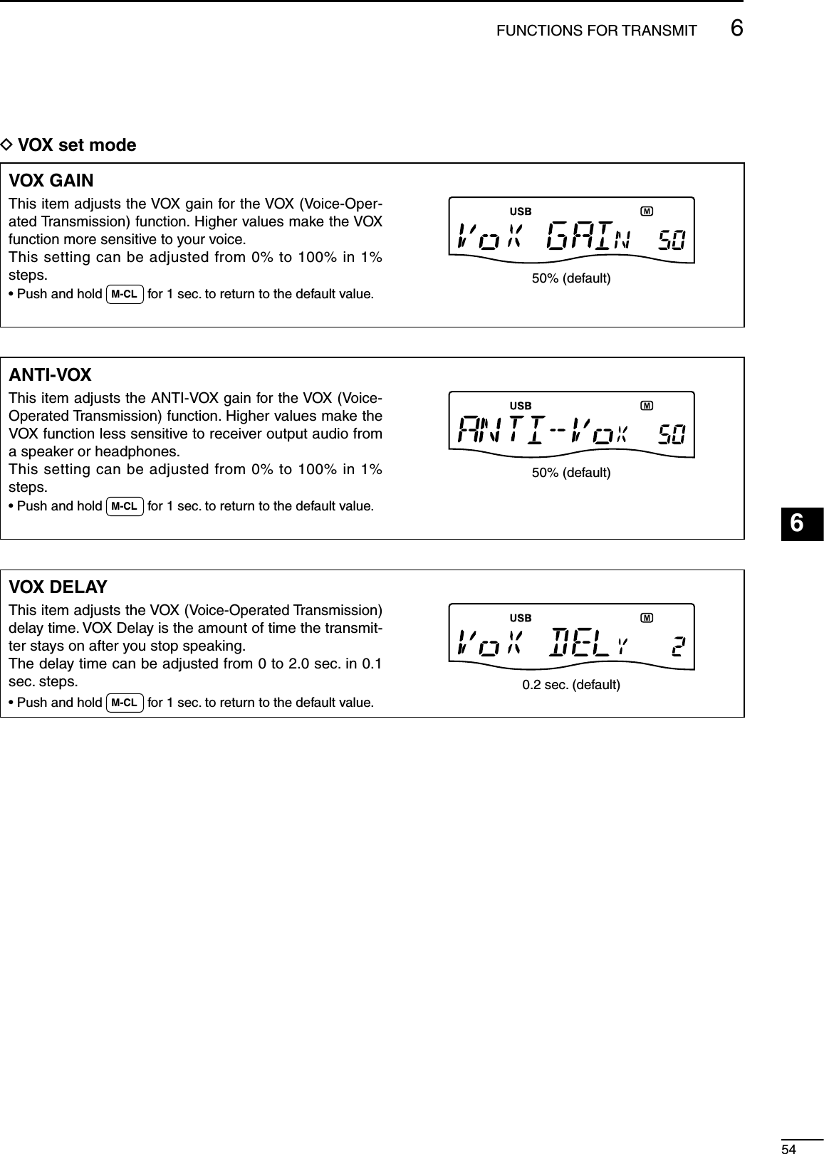
![556FUNCTIONS FOR TRANSMITN Break-in functionThe break-in function is used in CW mode to auto-matically switch the transceiver between transmit and receive when keying. The IC-7200 is capable of full break-in or semi break-in. Break-in operation is also referred to as QSK.D Semi break-in operationDuring semi break-in operation, the transceiver im-mediately transmits when keying, then automati-cally returns to receive after a pre-set delay time has passed from when you stop keying. This is similiar to VOX operation for voice.q Push MODE to select CW or CW-R mode. • When CW mode is selected, push and hold MODE for 1 sec. to toggle between CW and CW-R modes.w Set the semi break-in function ON in the set mode.q Push and hold M-CH/RITSET for 1 sec. twice to enter the set mode.w Rotate [M-CH] to select “BK-IN” to set the CW break-in operation.e Rotate [DIAL] to select “SE.” • FL : Full break-in • SE : Semi break-in • OF : Break-in OFFr Rotate [M-CH] to select “BK-DELAY” to select the CW delay time when semi break-in opera-tion is selected in step e.t Rotate [DIAL] to set the desired delay time. • The delay time is selectable from 0.2 to 13.0 (dots) in 0.1 (dots) steps.y Push M-CH/RITSET to exit the set mode and return to normal operation.e “BK” appears on the LCD. When using a paddle, set “KEY SPD” in the quick set mode to adjust the keying speed. (p. 72)MODETUNERTSFILTERSPCHV/MA/BSPLITM-CLSCANSETATTP.AMPCOMPVOXMNFRIT123456780502818141021 24=73.51.8F-INPM-CH/RITENTBANDGENE9.AGCMWANFMETERNRNB[DIAL] [M-CH]Appears7.5 dotsSemi break-in operation](https://usermanual.wiki/ICOM-orporated/301500/User-Guide-977157-Page-60.png)
![566FUNCTIONS FOR TRANSMIT123456789101112131415161718192021D Full break-in operationDuring full break-in operation, the transceiver auto-matically switches to receive between keying dots and dashes so that the operator can hear activity on the channel when transmitting.q Push MODE to select CW or CW-R mode. • When CW mode is selected, push and hold MODE for 1 sec. to toggle between CW and CW-R modes.w Set the full break-in function ON in the set mode.q Push and hold M-CH/RITSET for 1 sec. twice to enter the set mode.w Rotate [M-CH] to select “BK-IN” to set the CW break-in operation.e Rotate [DIAL] to select “FL.” • FL : full break-in • SE : semi break-in • OF : break-in OFFr Push M-CH/RITSET to exit the set mode and return to normal operation.e “F-BK” appears on the LCD. When using a paddle, set “KEY SPD” in the quick set mode to adjust the keying speed. (p. 72)MODETUNERTSFILTERSPCHV/MA/BSPLITM-CLSCANSETATTP.AMPCOMPVOXMNFRIT123456780502818141021 24=73.51.8F-INPM-CH/RITENTBANDGENE9.AGCMWANFMETERNRNB[DIAL] [M-CH]AppearsFull break-in operation](https://usermanual.wiki/ICOM-orporated/301500/User-Guide-977157-Page-61.png)
![576FUNCTIONS FOR TRANSMITN Speech compressorThe IC-7200 has a built-in, low distortion speech com-pressor circuit. This circuit increases your average talk power in SSB mode and is especially useful for DX-ing or noisy conditions when the receiving station is having difficulty copying your signal.q Push MODE to select an SSB mode. • When SSB mode is selected, push and hold MODE for 1 sec. to toggle between USB and LSB modes.w Push COMP to turn the speech compressor func-tion ON and OFF. • “” appears when the speech compressor func-tion is ON.MODETUNERTSFILTERSPCHV/MA/BSPLITM-CLSCANSETATTP.AMPCOMPVOXMNFRIT123456780502818141021 24=73.51.8F-INPM-CH/RITENTBANDGENE9.AGCMWANFMETERNRNB[DIAL]AppearsCOMP721D Compression level setting• Microphone gain settingMODETUNERTSFILTERSPCHV/MA/BSPLITM-CLSCANSETATTP.AMPCOMPVOXMNFRIT123456780502818141021 24=73.51.8F-INPM-CH/RITENTBANDGENE9.AGCMWANFMETERNRNB[DIAL] [M-CH]q Push MODE to select an SSB mode. • When SSB mode is selected, push and hold MODE for 1 sec. to toggle between USB and LSB modes.w Push COMP to turn the speech compressor func-tion OFF, if it’s ON. • “ ” disappears.e Push and hold ANFMETER for 1 sec. several times to select ALC meter. • “ALC” appears.r Adjust the MIC gain in the quick set mode.q Push and hold M-CH/RITSET for 1 sec. to enter the quick set mode.w Rotate [M-CH] to select “MIC GAIN” to set the microphone gain.e While transmitting, speak at a normal voice level and rotate [DIAL] to adjust the microphone gain so that the ALC meter reads within the ALC zone, whether you speak softly or loudly. • Push and hold M-CL for 1 sec. to return to the de-fault value.r Push M-CH/RITSET to exit the quick set mode and return to normal operation.• Compression level settingq Push and hold ANFMETER for 1 sec. several times to select ALC meter. • “ALC” appears.w Push and hold COMP for 1 sec. to enter the speech compression level set mode. • The speech compressor function is turned ON and “” appears. You can enter the speech compression level set mode before selecting ALC meter in step q.e While transmitting, speak at a normal voice level and rotate [DIAL] to adjust the speech compres-sion level so that the ALC meter reads within the ALC zone, whether you speak softly or loudly. • The speech compression level can be adjusted from 0 to 10. • Push and hold M-CL for 1 sec. to return to the default value.Level 5 (default)ALC zoner Push COMP to exit the speech compression level set mode and return to normal operation.t Push COMP to turn the speech compressor func-tion OFF if necessary. • “ ” disappears. NOTE: When the ALC meter peaks above the ALC zone, your transmitted voice may be distorted.](https://usermanual.wiki/ICOM-orporated/301500/User-Guide-977157-Page-62.png)
![586FUNCTIONS FOR TRANSMIT123456789101112131415161718192021N Split frequency operationSplit frequency operation allows you to transmit and receive in the same mode on two different frequen-cies. The split frequency operation is performed using 2 frequencies in VFO A and VFO B. The transmit and receive frequencies must be in the same bandThe following is an example of setting 7.0620 MHz for receiving and 7.0750 MHz for transmitting.MODETUNERTSFILTERSPCHV/MA/BSPLITM-CLSCANSETATTP.AMPCOMPVOXMNFRIT123456780502818141021 24=73.51.8F-INPM-CH/RITENTBANDGENE9.AGCMWANFMETERNRNB[DIAL] [M-CH]F-INP ENTBANDA/B2=3.5SPLIT37Keypadq Push A/B= to select VFO A.w Set the frequency to 7.0620 MHz and mode to LSB. (pgs. 25, 29)e Push SPLIT to turn the split function ON. • “ ” appears on the LCD.Appearsr Push and hold A/B= for 1 sec. to equalize the un-displayed VFO B frequency and operating mode with the displayed VFO A.t Push A/B= to select the VFO B.y Set the frequency to 7.0750 MHz (LSB). (p. 25)u Push A/B= to return to the VFO A.i Now you can receive on 7.0620 MHz and transmit on 7.0750 MHz. To swap the transmit and receive frequencies, push A/B= to exchange the VFO A and VFO B. CONVENIENT!M QUICK SPLIT FUNCTION (p. 59)When you push and hold SPLIT for 1 sec., the split function is activated, and the undisplayed VFO is set the same as the displayed VFO. (This operation is same as the steps e and r as at left.)This shortens the time needed to start split fre-quency operation.Quick split function is turned ON by default but can be turned OFF in the set mode (p. 76).M XFC FUNCTION (p. 76)When the XFC (transmit frequency check) function is ON, the transmit frequency can be changed (this operation is same as the steps t and y as at left.) NOTE: When the XFC function is ON, the RIT cal-culation function (p. 44) is not available.q Set the XFC (transmit frequency check) function ON in the set mode.q Push and hold M-CH/RITSET for 1 sec. twice to enter the set mode.w Rotate [M-CH] to select “XFC.”e Rotate [DIAL] to select ON.r Push M-CH/RITSET to exit the set mode and return to normal operation.w While pushing and holding RIT , the transmit fre-quency is indicated. And rotate [DIAL] to set the transmit frequency.](https://usermanual.wiki/ICOM-orporated/301500/User-Guide-977157-Page-63.png)
![596FUNCTIONS FOR TRANSMITD Quick split functionWhen you find a DX station, an important considera-tion is how to set the split frequency.When you push and hold SPLIT for 1 sec., the split function is activated, and the undisplayed VFO is set the same as the displayed VFO.This shortens the time needed to start split fre-quency operation.Quick split operation is turned ON by default but can be turned OFF in the set mode (p. 76).The following is an example of setting 7.0620 MHz for receiving and 7.0750 MHz for transmitting.q Select VFO A. • Pushing A/B= toggles VFO A and VFO B.w Set the frequency to 7.0620 MHz and mode to LSB. (pgs. 25, 29)e Push and hold SPLIT for 1 sec. to turn the split function ON and equalize the undisplayed VFO B frequency and operating mode with the displayed VFO A. • “ ” appears on the LCD.r Set the XFC (transmit frequency check) function ON in the set mode. (pgs. 58, 76) • The default setting is OFF.t While pushing and holding RIT , rotate [DIAL] to set the transmit frequency to 7.0750 MHz.y Now you can receive on 7.0620 MHz and transmit on 7.0750 MHz.MODETUNERTSFILTERSPCHV/MA/BSPLITM-CLSCANSETATTP.AMPCOMPVOXMNFRIT123456780502818141021 24=73.51.8F-INPM-CH/RITENTBANDGENE9.AGCMWANFMETERNRNB[DIAL] [M-CH]F-INP ENTBANDA/B2=3.5SPLIT37KeypadAppearsD Split lock functionAccidentally releasing RIT while rotating [DIAL] changes the receive frequency. To prevent this, use both the split lock and dial lock functions to change the transmit frequency only. The split lock func-tion cancels the dial lock function while pushing and holding RIT during split frequency operation.The dial lock’s effectiveness during split frequency operation can be selected in the set mode for both receive and transmit frequencies; or only the receive frequency. (p. 76)When the split lock function is ON, the transmit fre-quency cannot be adjusted by rotating [DIAL] while pushing and holding [PTT] even if the lock function is not activated.q Set the split lock function ON in the set mode.q Push and hold M-CH/RITSET for 1 sec. 2 times to enter the set mode.w Rotate [M-CH] to select “SPLIT LK.”e Rotate [DIAL] to select ON.r Push M-CH/RITSET to exit the set mode and return to normal operation.w During split operation, push and hold SPCH for 1 sec. to turn the dial lock function ON. • “ ” appears on the LCD.e While pushing and holding RIT *, the transmit frequency and mode are indicated. And Rotate [DIAL] to set the transmit frequency.*XFC function is should be turned ON in advance. (p. 76)](https://usermanual.wiki/ICOM-orporated/301500/User-Guide-977157-Page-64.png)
![606FUNCTIONS FOR TRANSMIT123456789101112131415161718192021NMeasuring SWRThe IC-7200 has a built-in circuit for measuring an-tenna SWR—no external equipment is necessary.q Push MODE to select CW or RTTY mode.w Confirm that the output power is over 30 W.e Push and hold ANFMETER for 1 sec. several times to select the SWR meter.r Push [PTT] to transmit; then read the actual SWR from the meter. • ≤ 1.5 well-matched antenna • > 1.5 may indicate an antenna out of its well-matched frequency range. If much larger than 2.0, check an-tenna and cable connections, etc.MODETUNERTSFILTERSPCHV/MA/BSPLITM-CLSCANSETATTP.AMPCOMPVOXMNFRIT123456780502818141021 24=73.51.8F-INPM-CH/RITENTBANDGENE9.AGCMWANFMETERNRNBAppears The best match is in this range.](https://usermanual.wiki/ICOM-orporated/301500/User-Guide-977157-Page-65.png)
![761MEMORY OPERATIONNMemory channelsThe transceiver has 201 memory channels including 2 scan edge channels.Memory mode is very useful for quickly changing to often-used frequencies.All 201 memory channels are tuneable which means the programmed frequency can be tuned temporarily with [DIAL], etc., in memory mode.MEMORYCHANNELMEMORYCHANNELNUMBERCAPABILITY COPYTO VFOOVER-WRITING CLEARRegular memory channels1–199 Independent transmit and receive frequencies and mode in each memory channel. Ye s Ye s Ye sScan edge memory channelsP1, P2 One frequency and one mode in each memory channel as scan edges for programmed scan. Yes Yes NoNMemory channel selectionq Push V/M to select memory mode. • “ ” appears.w Rotate [M-CH] to select the desired memory channel. • If the RIT control indicator lights red, push M-CH/RITSET to turn the RIT function OFF. (See below for details) • All memory channels including blank channels can be selected. • [UP]/[DN] on the microphone also selects the mem-ory channels. (The only programmed memory chan-nels are selectable.)Channel decreasesChannel increasesRIT control indicatorgoes outAbout the [M-CH] control: When the RIT control indicator lights red, the memory channels cannot be selected with rotat-ing the [M-CH] control because the [M-CH] con-trol acts as the RIT control. So, push M-CH/RITSET to set the [M-CH] control to memory channel control (RIT control indicator goes out).MODETUNERTSFILTERSPCHV/MA/BSPLITM-CLSCANSETATTP.AMPCOMPVOXMNFRIT123456780502818141021 24=73.51.8F-INPM-CH/RITENTBANDGENE9.AGCMWANFMETERNRNB[M-CH]RIT controlindicator[EXAMPLE]: Selecting memory channel 17.PushAppearsRotate [M-CH]VFO modeMemory modeChannel 17 is selected.](https://usermanual.wiki/ICOM-orporated/301500/User-Guide-977157-Page-66.png)
![627MEMORY OPERATION123456789101112131415161718192021NMemory programmingMemory channel programming can be performed either in VFO mode or in memory mode.D Programming in VFO modeq Push V/M to select VFO mode.w Rotate [DIAL], and push MODE to set the de-sired frequency and operating mode.e Rotate [M-CH] to select the desired memory channel. • If the RIT control indicator lights red, push M-CH/RITSET . (p. 61) • “ ” appears if the selected memory channel is a blank channel (one without any stored frequencies).Channel decreasesChannel increasesRIT control indicatorgoes outr Push and hold MW for 1 sec. to program the displayed frequency and operating mode into the selected memory channel. • 3 beeps are emitted when memory programming is successful.[EXAMPLE]: Programming 7.088 MHz/LSB into ch 12. PushVFO modeRotate [DIAL] PushRotate [M-CH]Push and hold7.088 MHz/LSB are programmed into ch 12.D Programming in memory modeq Push V/M to select memory mode.w Rotate [M-CH] to select the desired memory channel. • If the RIT control indicator lights red, push M-CH/RITSET . (p. 61) • Memory channel contents appear in the display.Channel decreasesChannel increasesRIT control indicatorgoes oute Rotate [DIAL], and push MODE to set the de-sired frequency and operating mode. • To program a blank channel, use direct frequency entry with the keypad. (p. 25)r Push and hold MW for 1 sec. to program the displayed frequency and operating mode into the memory channel. • 3 beeps are emitted when memory programming is successful.[EXAMPLE]: Programming 21.280 MHz/USB into ch 18.PushMemory modeRotate [DIAL] PushRotate [M-CH]Push and hold21.280 MHz/USB are programmed into ch 18.](https://usermanual.wiki/ICOM-orporated/301500/User-Guide-977157-Page-67.png)
![63NFrequency copyingThe frequency and operating mode in a memory channel can be copied to the VFO.D Copying in memory modeThis is useful for copying a memory channel’s con-tents (frequency and operating mode) to a VFO while operating in memory mode.This is useful when searching for signals around a memory channel frequency. NOTE: While operating in VFO mode, pushing and holding V/M for 1 sec. also copy a memory channel’s contents (frequency and operating mode) to a VFO. When you have changed the frequency or operat-ing mode in the selected memory channel: • Displayed frequency and mode are copied. • Programmed frequency and mode in the mem-ory channel are not copied, and they remain in the memory channel.q Push V/M to select memory mode.w Rotate [M-CH] to select the desired memory channel to be copied. • If the RIT control indicator lights red, push M-CH/RITSET . (p. 61) • Set the frequency or operating mode if required. • “” appears if the selected memory channel is a blank channel (and does not have contents). In this case copying is not possible.Channel decreasesChannel increasesRIT control indicatorgoes oute Push and hold V/M for 1 sec. to copy the fre-quency and operating mode into the VFO A. • 3 beeps are emitted when the copying is successful. • Displayed frequency and operating mode are copied to the VFO A.r To return to VFO mode, push V/M. • Copied frequency and operating mode appear in the display. You can return to VFO mode before copying the frequency and operating mode in step e.[EXAMPLE]: Copying contents of memory 16.Operating frequencyContents of memory 16: 14.020 MHz/CW: 14.018 MHz/CWV/M11.8Push and hold for 1 sec.,then push .V/M11.8Rotate [M-CH]7MEMORY OPERATION](https://usermanual.wiki/ICOM-orporated/301500/User-Guide-977157-Page-68.png)
![647MEMORY OPERATION123456789101112131415161718192021NMemory clearingAny unnecessary memory channels can be cleared. The cleared memory channels become blank chan-nels.q Push V/M to select memory mode.w Rotate [M-CH] to select the desired memory channel to be cleared. • If the RIT control indicator lights red, push M-CH/RITSET . (p. 61)e Push and hold M-CL for 1 sec. to clear the con-tents. • The programmed frequency and operating mode dis-appear and “ ” appears. • 3 beeps are emitted when memory clearing is suc-cessful.r To return to VFO mode, push V/M. NOTE: Be careful!— the contents of cleared memo-ries CANNOT be recalled.MODETUNERTSFILTERSPCHV/MA/BSPLITM-CLSCANSETATTP.AMPCOMPVOXMNFRIT123456780502818141021 24=73.51.8F-INPM-CH/RITENTBANDGENE9.AGCMWANFMETERNRNB[M-CH]Push and hold](https://usermanual.wiki/ICOM-orporated/301500/User-Guide-977157-Page-69.png)
![865SCAN OPERATION• ChannelsFor programmed scan:Program scan edge frequencies into scan edge mem-ory channels P1 and P2. (p. 66)For memory scan:Program two or more memory channels except scan edge memory channels.• Scan resume ON/OFFYou can select the scan to resume or cancel when detecting a signal in the set mode.Scan resume ON/OFF must be set before operating a scan. See p. 78 for ON/OFF setting and scan resume condition details.• Scan speedScan speed can be selected from 2 levels, high or low, in the set mode. See p. 78 for details.• Squelch conditionSCANSTARTSWITHPROGRAMMEDSCANMEMORYSCANSQUELCH OPENTS: 0.1/1 kHzThe scan continues un-til it is stopped manu-ally (pushing [SCAN] or closing the squelch), and does not pause even if signals are detected when the scan resume is ON. The scan pauses for 10 sec. when the squelch is closed, then resumes.TS: 5/9/10 kHzScan pauses on each step when the scan resume is ON; not appli-cable when OFF.Scan pauses on each channel when the scan resume is ON; not applicable when OFF.SQUELCH CLOSEDScan stops when a signal is detected.If you set scan resume ON in the set mode, the scan pauses for 10 sec. when detect-ing a signal, then resumes. When a signal disappears while scan is paused, scan resumes 2 sec. later.N Scan typesN PreparationPROGRAMMED SCANRepeatedly scans between two scan edge frequencies (scan edge memory channels P1 and P2).This scan operates in VFO mode.ScanScan edge P1 or P2 Scan edge P2 or P1JumpThis scan operates in memory mode.MEMORY SCANRepeatedly all programmed memory channels that are not blank.Mch 1 Mch 5Mch 2 Mch 3 Mch 4Mch 6Mch 7Mch 199BLANK](https://usermanual.wiki/ICOM-orporated/301500/User-Guide-977157-Page-70.png)
![668SCAN OPERATION123456789101112131415161718192021N Programmed scan operation (VFO mode)Programmed scan searches for signals between scan edge memory channels P1 and P2.The default frequencies for these memories are 0.500000 MHz and 29.99999 MHz, respectively.See p. 62 for scan edges programming.q Push V/M to select VFO mode.w Push MODE to select the desired operating mode. • The operating mode can be changed while scanning.e Push TS to select a tuning step. • The tuning step can be changed while scanning.r Set the [RF/SQL] control open or closed. • See the left page for squelch condition. • If the [RF/SQL] control function is set as “AUTO,” the squelch is always open in SSB, CW and RTTY modes. See pgs. 4, 30, 75 for details.t Push SCAN to start the scan. • “ ” appears while scanning.y When the scan detects a signal, the scan turns OFF, pauses or ignores it depending on the resume setting and the squelch condition.u To cancel the scan, push SCAN . NOTE: If the same frequencies are programmed into both scan edge memory channels P1 and P2, programmed scan does not start.MODETUNERTSFILTERSPCHV/MA/BSPLITM-CLSCANSETATTP.AMPCOMPVOXMNFRIT123456780502818141021 24=73.51.8F-INPM-CH/RITENTBANDGENE9.AGCMWANFMETERNRNB[RF/SQL]AppearsN Memory scan operation (Memory mode)Memory scan searches through memory channel 1 to 199 for signals. Blank (unprogrammed) memory channels are skipped.q Push V/M to select memory mode.w Close the squelch with the [RF/SQL] control.e Push SCAN to start the scan. • “ ” appears while scanning.r When the scan detects a signal, the scan stops or pauses depending on the resume setting.t To cancel the scan push SCAN . • Rotating [DIAL] during scan also cancels scan operation. NOTE: Two or more memory channels must be programmed for memory scan to start.MODETUNERTSFILTERSPCHV/MA/BSPLITM-CLSCANSETATTP.AMPCOMPVOXMNFRIT123456780502818141021 24=73.51.8F-INPM-CH/RITENTBANDGENE9.AGCMWANFMETERNRNB[RF/SQL]Appears](https://usermanual.wiki/ICOM-orporated/301500/User-Guide-977157-Page-71.png)
![967ANTENNA TUNER OPERATIONN Optional AT-180 AUTOMATIC ANTENNA TUNER operationThe AT-180 automatic antenna tuner matches the IC-7200 to the connected antenna automatically. Once the tuner matches an antenna, the variable capacitor settings are memorized as a preset point for each frequency range (100 kHz steps). Therefore, when you change the frequency range, the variable capacitors are automatically preset to the memorized point.NOTE: • The AT-180 can match both HF and 50 MHz bands. However, operation is different for the HF and 50 MHz bands. • When connecting the AT-180, the IC-7200’s out-put power must be more than 10 W. Otherwise, the AT-180 may not be tuned correctly. (AT-180’s minimum operating input power is 8 W.)CAUTION: NEVER transmit with the tuner ON when no antenna is connected. This will damage both the transceiver and antenna tuner.MODETUNERTSFILTERSPCHV/MA/BSPLITM-CLSCANSETATTP.AMPCOMPVOXMNFRIT123456780502818141021 24=73.51.8F-INPM-CH/RITENTBANDGENE9.AGCMWANFMETERNRNBTUNERD Tuner operation• For the HF band:Push TUNER to turn the tuner ON. The antenna is tuned automatically during transmission when the antenna SWR is higher than 1.5:1.• When the tuner is ON, “ ” indication appears.• For the 50 MHz band:Push and hold TUNER for 1 sec. to tune the antenna. If “ ” indicator blinks slowly while transmitting, push and hold TUNER for 1 sec. again to re-tune the antenna.D Manual tuningDuring SSB operation on HF bands at low voice lev-els, the AT-180 may not be tuned correctly. In such cases, manual tuning is helpful.Push and hold TUNER for 1 sec. to start manual tun-ing.• When CW mode is selected, a side tone is emitted, and “” indicator blinks; then, the previous mode is se-lected.If the tuner cannot reduce the SWR to less than 1.5:1 after 20 sec. of tuning, “ ” indicator disap-pears. In this case, check the following:• the antenna connection and feedline• the antenna SWR (p. 30; meter function, p 60; Measuring SWR)Through inhibit (HF bands only)The AT-180 has a through inhibit condition. When selecting this condition, the tuner can be used at poor SWR’s. In this case, automatic tuning in the HF bands activates only when exceeding SWR 3:1. Therefore, manual tuning is necessary each time you change the frequency. Although termed “through in-hibit,” the tuner will be set to the “through” configura-tion if the SWR is higher than 3:1 after tuning.CONVENIENT• Tuner sensitive condition (HF bands only)If you require critical tuning at any time during trans-mission, select the tuner sensitive condition. See p. 68 for selection.• Automatic tuner start (HF bands only)If you want to turn OFF the tuner under conditions of VSWR 1.5:1 or less, use “automatic tuner on” and turn the tuner OFF. See p. 76 for the automatic tuner function.• PTT tune function (p. 76)The AT-180 is tuned when [PTT] is pushed after the frequency is changed (more than 1%) if the AT-180 is turned ON. This function removes the “push and hold TUNER ” operation and activates first transmission on the new frequency.This function is turned ON in the set mode.](https://usermanual.wiki/ICOM-orporated/301500/User-Guide-977157-Page-72.png)
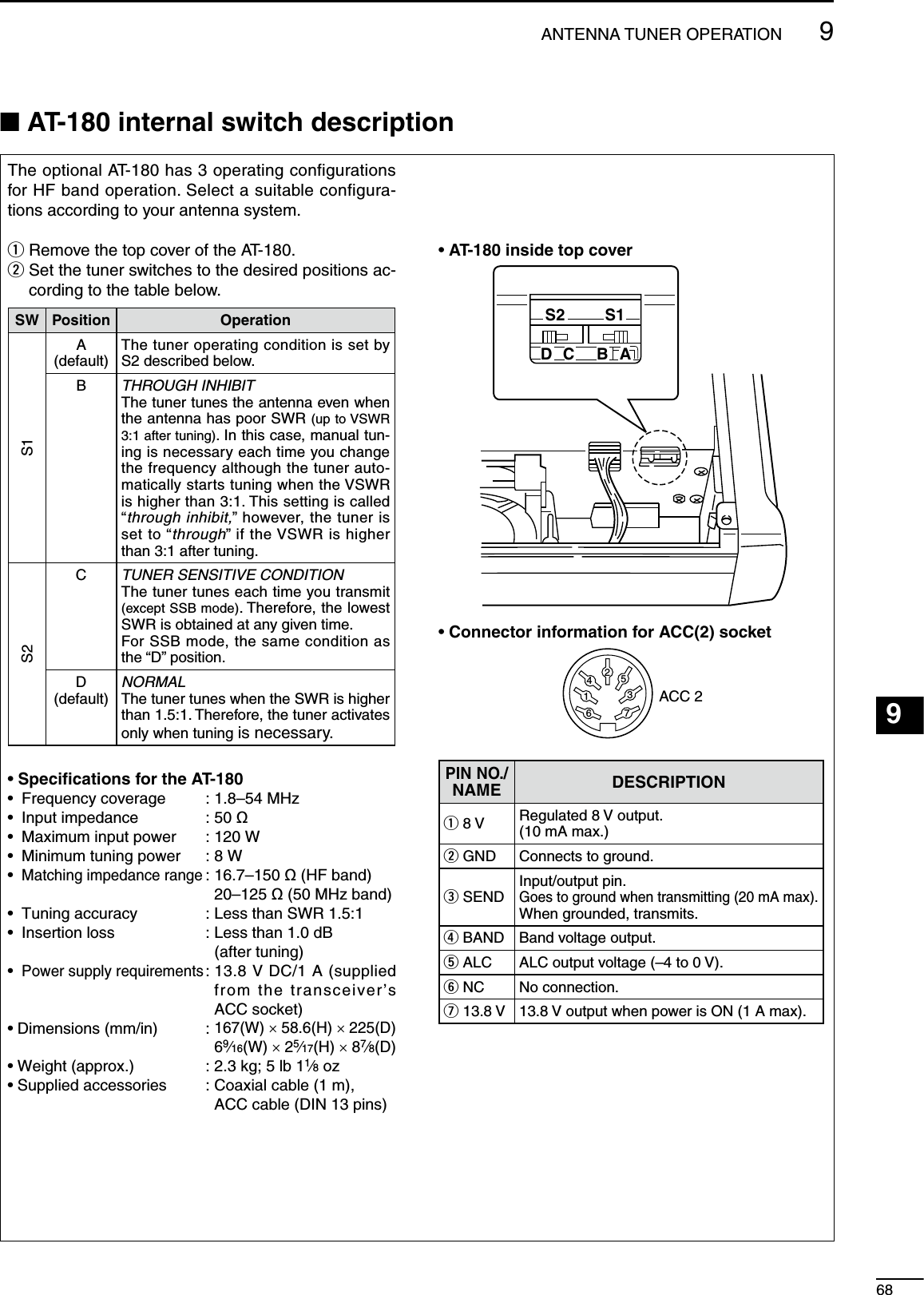
![699ANTENNA TUNER OPERATIONN Optional AH-4 AUTOMATIC ANTENNA TUNER operationThe AH-4 matches the IC-7200 to a long wire antenna more than 7 m/23 ft long (3.5 MHz and above).• See p. 14 for connection.• See the AH-4 instruction manual for AH-4 installation and antenna connection details.AH-4 setting example:For mobile operation For outdoor operation Long wireOptional AH-2bantenna elementR DANGER!: HIGH VOLTAGE!NEVER touch the antenna element while tuning or transmitting.NEVER operate the AH-4 without an antenna wire. The tuner and transceiver will be damaged.NEVER operate the AH-4 when it is ungrounded.Transmitting before tuning may damage the trans-ceiver. Note that the AH-4 cannot tune when using a 1⁄2λ long wire or on a multiple of that frequency.D AH-4 operationTuning is required for each frequency. Be sure to re-tune the antenna before transmitting when you change the frequency—even slightly.q Set the desired frequency in an HF band. • The AH-4 will not operate on frequencies outside of ham bands.w Push and hold TUNER for 1 sec. • “ ” indicator blinks while tuning.e “ ” indicator is still ON after the tuning is completed. • When the connected wire cannot be tuned, “ ” indicator goes out, and the AH-4 is bypassed and the antenna wire is connected to the antenna connector on the transceiver directly.r To bypass the AH-4 manually, push TUNER . • “ ” indicator goes out.Appears when the antenna tuner ON.Blinks while tuning.CONVENIENT• PTT tune function (p. 76)The AH-4 is always tuned when [PTT] is pushed after the frequency is changed (more than 1%). This function removes the “push and hold TUNER ” op-eration and activates first transmission on the new frequency.This function is turned ON in the set mode.](https://usermanual.wiki/ICOM-orporated/301500/User-Guide-977157-Page-74.png)
![1070SET MODE123456789101112131415161718192021N GeneralSet mode is used for programming infrequently changed values or conditions of functions.The IC-7200 has 2 separate set modes: quick set mode and set mode.SETM-CH/RITSETM-CH/RITSETM-CH/RITPush and holdfor 1 sec.PushmomentarilyPushmomentarilyPush and holdfor 1 sec.Quick set mode Set modeNormal operation modeD Quick set mode operationq Push and hold M-CH/RITSET for 1 sec. to enter the quick set mode.w Rotate [M-CH] to select the desired item.e Set the desired condition or value using [DIAL]. • Push and hold M-CL for 1 sec. to select the default condition or value.r Repeat w and e to set other items.t Push M-CH/RITSET to exit the quick set mode and re-turn to normal operation. [DIAL]MODETUNERTSFILTERSPCHV/MA/BSPLITM-CLSCANSETATTP.AMPCOMPVOXMNFRIT123456780502818141021 24=73.51.8F-INPM-CH/RITENTBANDGENE9.AGCMWANFMETERNRNB[M-CH]D Set mode operationq Push and hold M-CH/RITSET for 1 sec. to enter the quick set mode.w Repeat step q again to enter the set mode.e Rotate [M-CH] to select the desired item.r Set the desired condition or value using [DIAL]. • Push and hold M-CL for 1 sec. to select the default condition or value.t Repeat e and r to set other items.y Push M-CH/RITSET to exit the set mode and return to normal operation.[DIAL]MODETUNERTSFILTERSPCHV/MA/BSPLITM-CLSCANSETATTP.AMPCOMPVOXMNFRIT123456780502818141021 24=73.51.8F-INPM-CH/RITENTBANDGENE9.AGCMWANFMETERNRNB[M-CH]](https://usermanual.wiki/ICOM-orporated/301500/User-Guide-977157-Page-75.png)
![N Quick set modeMode Set mode item Default settingSSB1 RF POWER 100%2 MIC GAIN 50%3 DATA MODE OFFCW1 RF POWER 100%2 KEY SPEED 20WPM3 CW PITCH 600Hz4 SIDE TONE LEVEL 30%5 SIDE TONE LIMIT ONRTTY1 RF POWER 100%2 TWIN PEAK FILTER OFF3 RTTY MARK TONE 2125Hz4 RTTY SHIFT 170Hz5 RTTY KEY POLARITY NORMALAM1 RF POWER 100%2 MIC GAIN 50%3 DATA MODE OFFRF power (all modes)This item adjusts the RF output power. The RF output power can be adjusted from L (Low), 1% to 100% in 1% steps.100% (default)Mic gain (SSB/AM modes)This item adjusts microphone gain from 0% to 100% in 1% steps.50% (default)Data mode (SSB/AM modes)This item turns the data mode ON or OFF. When the data mode is turned ON, the audio input from the [ACC] connector* is used for transmission instead of [MIC] connector and the speech compressor function is turned OFF.* The desired connector can be selected. (p. 77)on : Data mode operation is enabled. (“ ” appears.)oF : Data mode operation is disabled. (“ ” disappears.)OFF (default)7110 SET MODE](https://usermanual.wiki/ICOM-orporated/301500/User-Guide-977157-Page-76.png)
![7210SET MODE123456789101112131415161718192021Key speed (CW mode)This item adjusts the CW key speed. The key speed can be selected from 6 to 60* wpm.* 39, 43, 45, 47, 49, 51, 53, 55, 56, 58 and 59 cannot be selected.20 WPM (default)CW pitch (CW mode)This item adjusts the CW receive pitch. The pitch can be selected from 300 to 900 Hz in 10 Hz steps.600 Hz (default)Side tone level (CW mode)This item adjusts the CW side tone level from 0% to 100% in 1% steps.30% (default)Side tone level limit (CW mode)This item allows you to set a maximum volume level for CW side tone. CW side tone is linked to the [AF] control until a specified volume level is reached—further rotation of the [AF] control will not increase the volume of the CW side tones.on : CW side tone level is limited with the [AF] control.oF : CW side tone level is linked to the [AF] control.ON (default)Twin peak filter (RTTY mode)This item turns the twin peak filter ON or OFF. on : Twin peak filter is ON.oF : Twin peak filter is OFF. NOTE: The RTTY mark frequency (2125 Hz) and shift width (170 Hz) are automatically set when the twin peak filter is ON.OFF (default)RTTY mark tone (RTTY mode)This item selects the RTTY mark frequency. There are 3 selectable values: 1275, 1615 and 2125 Hz. NOTE: 2125 Hz is automatically set when the twin peak filter is ON. 2125 Hz (default)](https://usermanual.wiki/ICOM-orporated/301500/User-Guide-977157-Page-77.png)
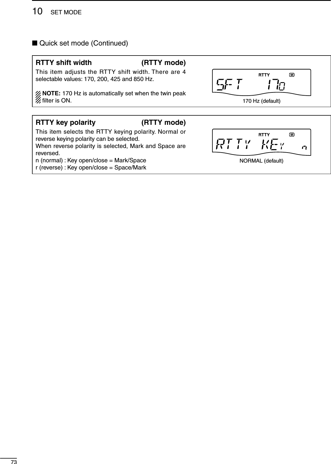
![7410SET MODE123456789101112131415161718192021N Set modeSet mode item Default setting Set mode item Default setting 1 LCD BACKLIGHT HIGH 22 SCAN RESUME ON 2 BEEP ON 23 MAIN DIAL AUTO TS HIGH 3 BAND EDGE BEEP ON 24 DIAL 1⁄4OFF 4 BEEP LEVEL 50% 25 MIC UP/DOWN SPEED HIGH 5 BEEP LEVEL LIMIT ON 26 SSB/CW SYNCHRONOUS TUNING OFF 6 RF/SQL CONTROL RF + SQL 27 CW NORMAL SIDE LSB 7 METER PEAK HOLD ON 28 BREAK-IN OFF 8 QUICK SPLIT ON 29 BREAK-IN DELAY 7.5 DOTS 9 SPLIT LOCK OFF 30 DOT/DASH RATIO 1:1:3.0 10 XFC OFF 31 PADDLE POLARITY NORMAL 11 AUTO TUNE OFF 32 KEYER TYPE ELEC-KEY 12 PTT TUNE OFF 33 MIC UP/DOWN KEYER OFF 13 MODULATION INPUT (DATA OFF) MIC/ACC 34 MODE SELECT (SSB) ON 14 MODULATION INPUT (DATA ON) ACC 35 MODE SELECT (CW) ON 15 USB LEVEL 50% 36 MODE SELECT (RTTY) ON 16 SPEECH LEVEL 50% 37 MODE SELECT (AM) ON 17 SPEECH LANGUAGE ENGLISH 38 CI-V BAUD RATE AUTO 18 SPEECH SPEED HIGH 39 CI-V ADDRESS 76H 19 SPEECH S-LEVEL ON 40 CI-V TRANSCEIVE ON 20 SPEECH [MODE] KEY OFF 41 REFERENCE FREQUENCY ADJUSTMENTDefault setting is differ-ent for each transceiver. 21 SCAN SPEED HIGHLCD BacklightThis item adjusts the brightness of the LCD from HI (High), Lo (Low) or oF (Off).High (default)BeepA beep sounds each time a key is pushed to confirm it. This function can be turned OFF for silent operation.on : Confirmation beep ONoF : Confirmation beep OFFThe volume level can be set in “Beep Level” as below. ON (default)](https://usermanual.wiki/ICOM-orporated/301500/User-Guide-977157-Page-79.png)
![7510 SET MODEN Set mode (Continued)Band Edge BeepA beep sounds when an operating frequency enters or exits an amateur band. This function is independent from “Beep” (the confirmation beep) setting as above.on : Band edge beep ONoF : Band edge beep OFFThe volume level can be set in “Beep Level” as below.ON (default)Beep LevelThis item sets the maximum volume level for the con-firmation beep and band edge beep tones from 0% to 100% in 1% steps. When beep tones are set to OFF, this setting has no ef-fect. 50% (default)Beep Level LimitTurn the beep tones output level limiting capability ON and OFF for the confirmation and band edge beep tones. When this item is set to ON, the beep tones are linked to the [AF] control until rotation of the [AF] control reaches to the specified level—further rotation will not increase the volume of the beep tones.on : Beep level is limited with the [AF] controloF : Beep level is linked to the [AF] controlON (default)RF/SQL ControlThe [RF/SQL] control can be set as the RF/squelch con-trol, the squelch control only (RF gain is fixed at maxi-mum) or Auto (RF gain control in SSB, CW and RTTY; squelch control in AM).See pgs. 4, 30 for details.rS (RF+SQL) : [RF/SQL] control is set as the RF/squelch controlSq (SQL) : [RF/SQL] control is set as the squelch controlAt (AUTO) : [RF/SQL] control is set as the RF gain control in SSB, CW and RTTY; squelch control in AMRF + SQL (default)Meter Peak HoldThis item turns the meter peak hold function ON or OFF.on : The highest activated segment of the meter remains visible for 0.5 sec.oF : The meter functions normally.ON (default)](https://usermanual.wiki/ICOM-orporated/301500/User-Guide-977157-Page-80.png)
![7610SET MODE123456789101112131415161718192021Quick SplitThis item turns the quick split function ON or OFF.When this item is set to ON, push and hold SPLIT for 1 sec. to set the undisplayed VFO frequency and oper-ating mode are set the same as the displayed VFO fre-quency and operating mode.See pgs. 58, 59 for details.on : The quick split function ONoF : The quick split function OFFON (default)Split LockThis item turns the split lock function ON or OFF.When this item is set to ON, the transmit frequency can be adjusted by rotating [DIAL] while pushing and holding RIT * even if the lock function is activated. * The transmit frequency check function (“XFC”; p. 76) must be turned ON in advance.See p. 59 for split frequency operation details.on : The split lock function ONoF : The split lock function OFFOFF (default)XFCThis item turns the XFC (transmit frequency check) func-tion ON or OFF.on : The transmit frequency can be monitored while pushing and holding RIToF : The transmit frequency check function OFF NOTE: When the XFC function is turned ON, the RIT calculation function (p. 44) is not available.OFF (default)Auto TuneThe optional AT-180 ANTENNA TUNER has an automatic start capability which starts tuning if the SWR is higher than 1.5:1.on : The automatic tune starts even when the tuner is turned OFF during HF bands operation.oF : The tuner remains OFF even when the SWR is poor (1.5:1)OFF (default)PTT TuneTuning of the internal antenna tuner can be started auto-matically at the moment [PTT] is pushed after the operat-ing frequency is changed (more than 1% from last-tuned frequency).When an optional AT-180 ANTENNA TUNER is connected, the tuner function must be turned ON in advance.on : Tuning starts when [PTT] is pushed on a new frequency.oF : Tuning starts only when TUNER is pushed.OFF (default)](https://usermanual.wiki/ICOM-orporated/301500/User-Guide-977157-Page-81.png)
![7710 SET MODEN Set mode (Continued)Modulation input (Data OFF)Selects the desired connector(s) for modulation input when SSB data/AM data mode is not in use.M (MIC) : Use the signals from [MIC].A (ACC) : Use the signals from [ACC] (pin11).M A (MIC/ACC) : Use the signals from [MIC] and [ACC] (pin11).U (USB) : Use the signals from [USB].MIC/ACC (default)Modulation input (Data ON)Selects the desired connector(s) for modulation input when SSB data/AM data mode is in use.M (MIC) : Use the signals from [MIC].A (ACC) : Use the signals from [ACC] (pin11).M A (MIC/ACC) : Use the signals from [MIC] and [ACC] (pin11).U (USB) : Use the signals from [USB].ACC (default)USB LevelSets the input modulation level of the USB jack, within 0% to 100% in 1% steps.50% (default)Speech LevelThis item adjusts the volume level for the speech function from 0% to 100% in 1% steps.50% (default)Speech S-levelFrequency, mode and signal level can be announced by the voice synthesizer. The signal level announcement can be deactivated if desired.When “oF” is selected, the signal level is not announced.on : Signal level announcementoF : No signal level announcementON (default)](https://usermanual.wiki/ICOM-orporated/301500/User-Guide-977157-Page-82.png)
![7810SET MODE123456789101112131415161718192021Speech MODE KeyThis item selects whether the operating mode an-nounced with the speech synthesizer when MODE is pushed.When “on” is selected, the selected operating mode is announced at pushing MODE .on : Operating model announcement with MODE .oF : No operating mode announcement with MODE .OFF (default)Scan SpeedThis item sets the rate at which channels or frequencies are scanned during scan operations.High and low can be selected.HI : Fast scan.Lo : Slow scan. High (default)Scan ResumeThis item turns the scan resume function ON or OFF.on : Scan resumes 10 sec. after stopping on a signal (or 2 sec. after a signal disappears).oF : Scan does not resume after stopping on a signal.ON (default)Main Dial Auto TSThis item sets the auto tuning step function. When ro-tating [DIAL] rapidly, the tuning step rate adapts as se-lected.There are 2 type of auto tuning steps: HI (Fastest) and Lo (Faster).HI : Approx. 5 times faster when the tuning step is set to 1 kHz or smaller steps; approx. 2 times faster when the tuning step is set to 5 kHz or larger steps.Lo : Approx. 2 times fasteroF : Auto tuning step is turned OFF.High (default)Dial ¼This item turns the ¼-speed tuning function ON or OFF in CW, RTTY and SSB data modes.on : The ¼-speed tuning function ON for critical tuning. While operating in CW/RTTY/SSB data/AM data, the dial sensitivity is reduced to ¼ of normal.oF : The ¼-speed tuning function OFF. NOTE: This function is only available when the pro-grammable tuning step is OFF (p. 26).OFF (default)](https://usermanual.wiki/ICOM-orporated/301500/User-Guide-977157-Page-83.png)
![7910 SET MODEN Set mode (Continued)Mic Up/Down SpeedThis item sets the rate at which frequencies are scanned when the microphone [UP]/[DN] keys are pushed and held. HI : High speed (50 tuning steps/sec.)Lo : Low speed (25 tuning steps/sec.) High (default)SSB/CW Synchronous TuningThis item turns the displayed frequency shift function from ON or OFF.When this function is set to ON, the received signal will remain the same even when the operating mode is changed between SSB and CW.The amount of frequency shift will change according to the CW pitch setting.on : The displayed frequency shifts when the operating mode is changed between SSB and CW.oF : The displayed frequency does not shift.OFF (default)CW Normal SideSelects the carrier point of CW mode from LSB and USB.L (LSB) : LSB is the normal mode.U (USB) : USB is the normal mode.LSB (default)Break-InThis item selects break-in type for CW operation.Full break-in (QSK) activates the receiver between trans-mitted dots and dashes. This is useful when operating contests, when “fast responses” are common.Semi break-in keeps the receiver quiet between dots and dashes and automatically returns to receive after a pre-set time from when you stop keying.When break-in is turned off, the key or paddle can gener-ate side tones (selectable in quick set mode) but will not transmit.oF : No break-in operation.SE (Semi) : Semi break-in operation.FL (Full) : Full break-in operation.OFF (default)Break-In DelayThis item adjusts break-in delay time for CW semi break-in operation.The delay time is selectable from 0.2 to 13.0 (dots) in 0.1 (dots) steps.7.5 dots (default)](https://usermanual.wiki/ICOM-orporated/301500/User-Guide-977157-Page-84.png)
![8010SET MODE123456789101112131415161718192021Dot/Dash RatioThis item sets the internal electronic keyer dot/dash ratio.1:1:2.8 to 1:1:4.5 (in 0.1 steps) can be selected.Keying weight example: Morse code “K”DASHWeight setting:1:1:3 (default)Weight setting:AdjustedDASHDOT (Fixed*)Adjustable range SPACE (Fixed*)*SPACE and DOT length can be adjusted with “Key speed” only in the quick set mode.1:1:3.0 (default)Paddle PolarityThis item sets the paddle polarity.n (Normal) : Normal polarity.r (Reverse) : Reverse polarity.Normal (default)Keyer TypeThis item selects the keyer type for the [KEY] connector on the rear panel.EL : Internal electronic keyer is selected.bG : Internal electronic keyer is activated as BUG key.St : Internal electronic keyer is turned OFF, and a straight key or external electronic keyer can be used.ELEC-KEY (default)Mic Up/Down KeyerThis item allows you to set the microphone [UP]/[DN] switches to be used as a paddle.on : [UP]/[DN] switches can be used as a paddle for CW mode operation.oF : [UP]/[DN] switches cannot be used as a paddle for CW mode operation. NOTE: When “ON” is selected, the frequency and memory channel cannot be changed using the [UP]/[DN] switches.See p. 82 for the CW paddle connection to the MIC con-nector.OFF (default)](https://usermanual.wiki/ICOM-orporated/301500/User-Guide-977157-Page-85.png)
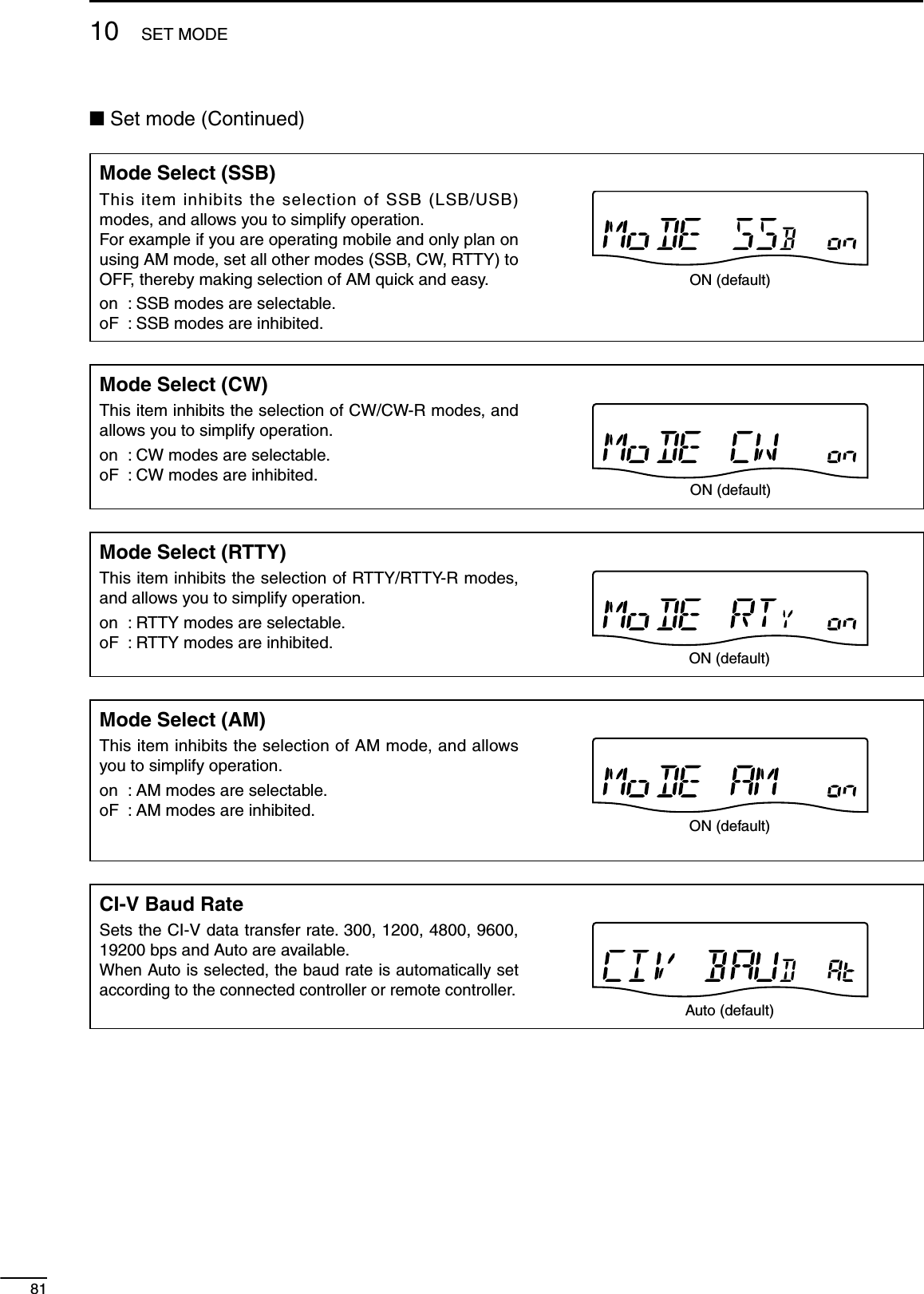
![CI-V AddressTo distinguish equipment, each CI-V transceiver has its own Icom standard address in hexadecimal code.The IC-7200’s address is 76h.When 2 or more IC-7200s are connected to an optional CT-17 CI-V LEVEL CONVERTER, rotate [DIAL] to select a different address for each IC-7200 in the range 01h to 7Fh.76 : Address of 76h76h (default)CI-V TransceiveTransceive operation is possible with the IC-7200 con-nected to other Icom HF transceivers or receivers.When “ON” is selected, changing the frequency, operat-ing mode, etc. on the IC-7200 automatically changes those of connected transceivers (or receivers) and vice versa.on : Transceive ONoF : Transceive OFFON (default)Reference Frequency AdjustmentAdjusts the internal reference signal frequency within 0% to 100% range in 1% steps during frequency calibration. NOTE: Default setting is different for each transceiver.D Paddle operation from [MIC] connectorConnect a CW paddle as at right to operate an elec-tronic keyer from the [MIC] connector.• Be sure to select “Paddle Polarity,” “Keyer Type” and “Mic Up/Down Keyer” in the set mode. (p. 80)• Connect straight key to “DOT” side.• Push both of “DOT” and “DASH” to activate the squeeze operation. MIC connectorCWpaddleDOTDASH3.9 kø ±5%2.2 kø ±5%MIC U/D eGND y8210SET MODE123456789101112131415161718192021](https://usermanual.wiki/ICOM-orporated/301500/User-Guide-977157-Page-87.png)
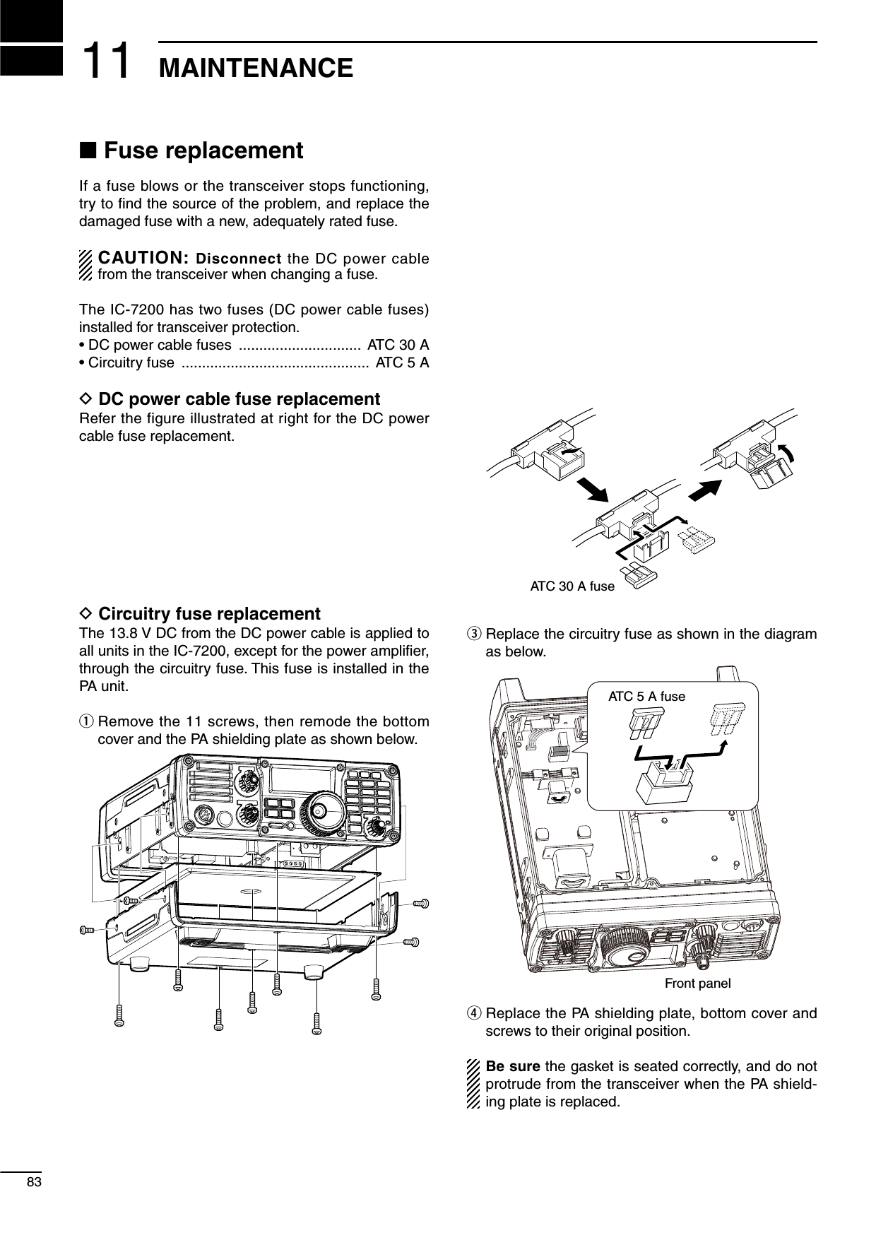
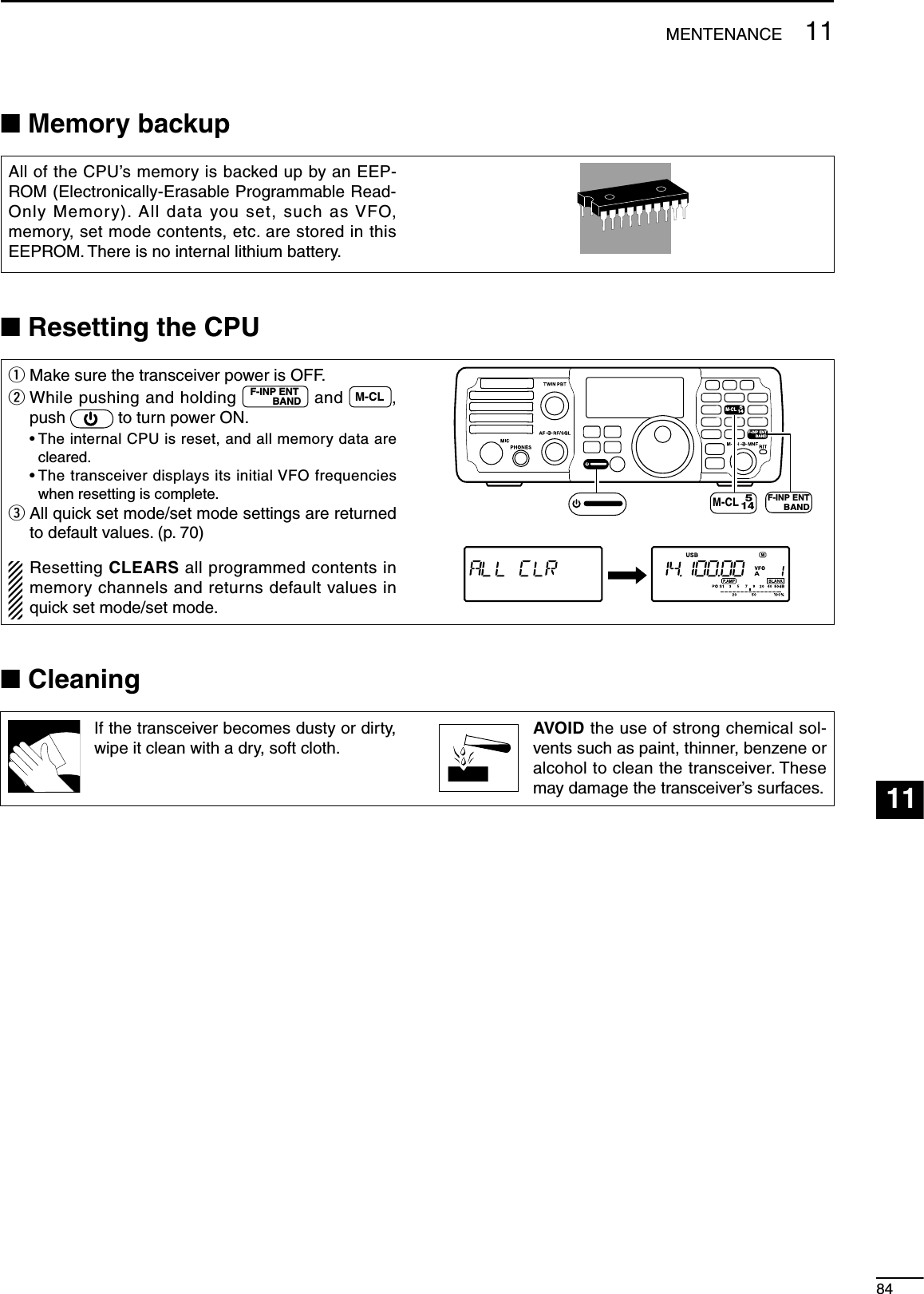
![1285TROUBLESHOOTINGThe following chart is designed to help you correct problems which are not equipment malfunctions.If you are unable to locate the cause of a problem or solve it through the use of this chart, contact your nearest Icom Dealer or Service Center.PROBLEM POSSIBLE CAUSE SOLUTION REF.POWER SUPPLYPower does not come on when [PWR] is pushed. • DC power cable is improperly connected.• Reconnect the power cable correctly. p. 15• Fuse is blown. • Check for the cause, then replace the fuse with a spare one. (Fuse is installed in the DC power cable)p. 83• Battery is exhausted if you are using a 12 V battery as the power source.• Check the battery voltage. —RECEIVENo sound comes from the speaker.• Volume level is set too low. • Rotate [AF] clockwise to obtain a suit-able listening level.p. 29• The squelch level is closed. • Tu r n [RF/SQL] to 10 o’clock position to open the squelch.p. 30• The transceiver is in the transmit mode. • Release [PTT] on the microphone or check the SEND line of an external unit, if connected.—• An external speaker or headphones are connected.• Check the external speaker or head-phone plug connection.p. 14Sensitivity is too low, and only strong signals are audible.• The antenna is not connected properly. • Reconnect to the antenna connector. —• The antenna feed line is cut or shorted. • Check the feed line and correct any im-proper conditions.—• The antenna is not properly tuned. • Push TUNER to manually tune the an-tenna.p. 67• The attenuator function is activated. • Push P.AMPATT to turn the function OFF. p. 45• The antenna for another band is se-lected.• Select an antenna suitable for the oper-ating frequency.p. 67Receive audio is dis-torted.• The operating mode is not selected cor-rectly.• Select a suitable operating mode. p. 29Receive signal is dis-torted by strong sig-nals.• The noise reduction is activated and the noise reduction level is too high.• Set the noise reduction level for maxi-mum readability.p. 50• Noise blanker function is activated. • Push NB to turn the function OFF. p. 49• Preamp is activated. • Push P.AMPATT to turn the function OFF. p. 45The shift frequency of the RIT function cannot be added/subtracted.• The XFC (transmit frequency check function) is turned ON.• Turn the XFC (transmit frequency check function) OFF in set mode.p. 76](https://usermanual.wiki/ICOM-orporated/301500/User-Guide-977157-Page-90.png)
![PROBLEM POSSIBLE CASE SOLUTION REF.TRANSMITTransmitting is impos-sible. • The operating frequency is not set in a ham band.• Set the frequency in a ham band. p. 25Output power is too low. • Power is set to a lower power than max-imum.• Set the output power in quick set mode. p. 71• Microphone gain is set too low. • Set microphone gain to a suitable level in quick set mode.p. 71• The antenna is not connected properly. • Reconnect the antenna connector. —• The antenna feed line is cut or shorted. • Check the feed line and correct any im-proper conditions.—• The antenna is not properly tuned. • Push TUNER to manually tune the an-tenna or test with dummy load.p. 67• The antenna for another band is se-lected.• Select an antenna suitable for the oper-ating frequency.p. 67No contact possible with other stations. • RIT function is activated. • Push RIT to turn the function OFF. p. 44• Split function is activated. • Push SPLIT to turn the function OFF. p. 58Transmitted signals are distorted. • Microphone gain is set too high. • Set microphone gain to a suitable level in quick set mode.p. 71• The compression level is set too high with the speech compressor ON.• Set compression level to a suitable po-sition.p. 57DISPLAYDisplayed frequency does not change prop-erly.• The dial lock function is activated. • Push SPCH to deactivate the function. p. 29• The internal CPU has malfunctioned. • Reset the CPU. pgs. 21,83SCANProgrammed scan does not stop.• [RF/SQL] is assigned to RF gain control and squelch is open.• Reset [RF/SQL] control assignment and set it to the threshold point.p. 30Programmed scan does not start.• The same frequencies have been pro-grammed in scan edge memory chan-nels.• Program different frequencies into scan edge memory channels.p. 62Memory scan does not start.• 2 or more memory channels have not been programmed.• Program 2 or more memory channels. p. 62MEMORYThe memory channels cannot be selected with rotating the [M-CH] control.• The [M-CH] control is in RIT control mode. • Push M-CH/RITSET to cancel the RIT func-tion (RIT control indicator goes out).p. 618612TROUBLESHOOTING123456789101112131415161718192021](https://usermanual.wiki/ICOM-orporated/301500/User-Guide-977157-Page-91.png)
![1387OPTION INSTALLATIONSN MB-116 HANDLES installationThe optional MB-116 HANDLES are convenient when moving the transceiver and can protect the face and radio knobs during transport.± Attach the MB-116 to the both sides of the trans-ceiver with the supplied screws (M4 × 9).Screws(M4 × 9)N MB-117 CARRYING HANDLE installationThe optional MB-117 CARRYING HANDLE is convenient when carrying the transceiver for DX-peditions, field operation, etc.q Attach the rubber feet to the [FOOT] holes on the right side of the transceiver with the supplied screws (M4 × 12).w Attach the MB-117 to the [CARRYING HANDLE] holes on the left side of the transceiver with the supplied screws (M3 × 10).Rubber feetCarrying handleScrews(M4 × 12)Screws (M3 × 10)N MB-118 MOBILE MOUNTING BRACKET installationThe universal mounting bracket allows overhead mounting.• Mount the transceiver securely with the 4 supplied screws (5 × 20) to a thick surface which can support more than 5.5 kg (12.1 lb). CAUTION: Non-supplied bolts (longer than 8 mm) may damage the internal units. NEVER install the MB-118 with the non-supplied screws and bolts.MB-118(Optional)Flat washerBolt(M4 × 8)Screw(5 × 20)Spring washer](https://usermanual.wiki/ICOM-orporated/301500/User-Guide-977157-Page-92.png)
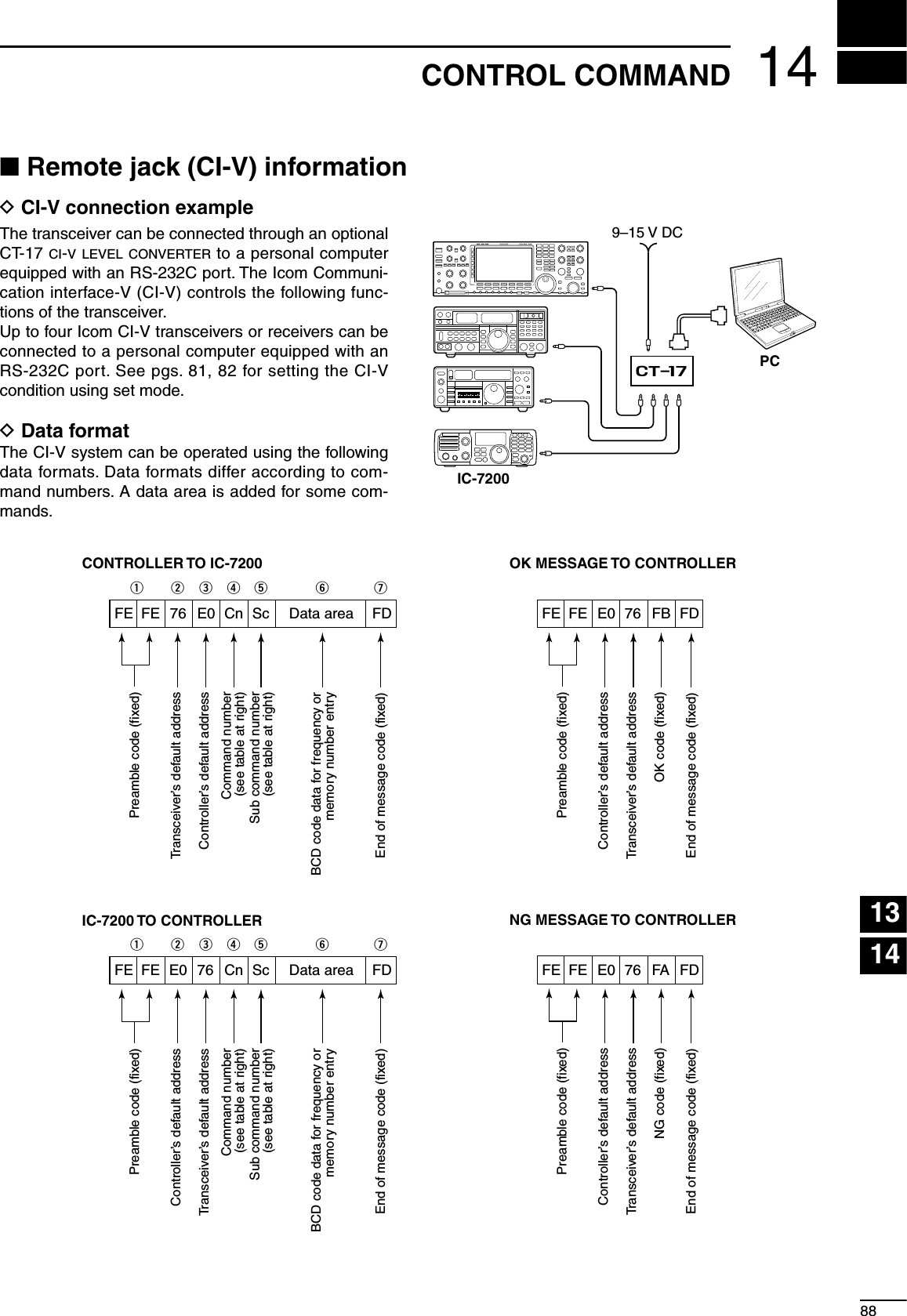
![D Command tableCommand Sub command Description 00 — Send frequency data. (for transceive operation) 01 00 Select LSB mode (for transceive operation) 01 Select USB mode (for transceive operation) 02 Select AM mode (for transceive operation) 03 Select CW mode (for transceive operation) 04 Select RTTY mode (for transceive operation) 07 Select CW-R mode (for transceive operation) 08 Select RTTY-R mode (for transceive operation) 02 — Read band edge frequencies 03 — Read operating frequency 04 — Read operating mode 05 — Set operating frequency 06 00 Select LSB mode 01 Select USB mode 02 Select AM mode 03 Select CW mode 04 Select RTTY mode 07 Select CW-R mode 08 Select RTTY-R mode 07 — Select VFO mode 00 Select VFO A 01 Select VFO B A0 Equalize VFO A and VFO B B0 Exchange VFO A and VFO B 08 — Select memory mode 0001−0201* Select memory channel *P1=0200, P2=0201 09 — Memory write 0A — Memory to VFO 0B — Memory clear 0E 00 Scan stop 01 Programmed/memory scan start 02 Programmed scan start 22 Memory scan start D0 Set scan resume OFF D3 Set scan resume ON 0F 00 Turn the split function OFF 01 Turn the split function ON 10 00 Select 10 Hz (or 1 Hz) tuning step 01 Select 100 Hz tuning step 02 Select 1 kHz tuning step 03 Select 5 kHz tuning step 04 Select 9 kHz tuning step 05 Select 10 kHz tuning step 11 — Set/read attenuator. ( 0=OFF, 20=ON (20 dB)) 13 00 Announce with voice synthesizer 01 ( 00=all data 01=frequency and 02 S-meter; 02=receive mode)Command Sub command Description 14 01 [AF] level setting (0=max. CCW to 255=max. CW) 02 [RF] level setting (0=max. CCW to 255=11 o'clock) 03 [SQL] level setting (0=11 o'clock to 255=max. CW) 06 NR level setting (0=0% to 255=100%) 07 Inside [PBT] setting (0= max. CCW, 128=center, 255=max. CW) 08 Outside [PBT] setting (0= max. CCW, 128=center, 255=max. CW) 09 CW Pitch setting (0=300 Hz to 255=900 Hz (5 Hz steps)) 0A RF power setting (0=minimum to 255=100%) 0B MIC gain setting (0=0% to 255=100%) 0C Key speed level setting (0=6 wpm to 255=60 wpm) 0D [MNF] setting (0=max. CCW, 128=center, 255=max. CW) 0E COMP level setting (0=0 to 255=10) 0F Break-IN delay setting (0=2.0 d to 255=13.0 d) 12 NB level setting (0=0% to 255=100%) 16 VOX gain setting (0=0% to 255=100%) 17 Anti VOX gain setting (0=0% to 255=100%) 15 01 Read squelch condition 02 Read S-meter level 11 Read RF power meter 12 Read SWR meter 13 Read ALC meter 16 02 Preamp (0=OFF, 1=ON) 12 AGC selection (0=OFF, 1=Fast, 2=Slow.) 22 Noise blanker (0=OFF, 1=ON) 40 Noise reduction (0=OFF, 1=ON) 41 Auto notch (0=OFF, 1=ON) 44 Speech compressor (0=OFF, 1=ON) 46 VOX function (0=OFF, 1=ON) 47 Break-IN function (0=OFF, 1=semi BK-IN, 2=full BK-IN) 48 Manual notch (0=OFF, 1=ON) 4F Twin peak filter (0=OFF, 1=ON) 50 Dial lock function (0=OFF, 1=ON) 19 00 Read the transceiver ID 1A 00 Set/read memory contents An additional code, 0001−0201 (0200=P1, 0201=P2), must be added to specify the memory channel. 01 Set/read band stacking register contents (see p. 24 for details) 02 Set/read the selected filter width ( SSB, CW, RTTY: 0=50 Hz to 40/31=3600/2700 Hz; AM: 0=200 Hz to 39=8 kHz) 0301 Set/read RF power setting (0=minimum to 255=100%) 0302 Set/read MIC gain setting (0=0% to 255=100%)8914 CONTROL COMMAND](https://usermanual.wiki/ICOM-orporated/301500/User-Guide-977157-Page-94.png)
![9014CONTROL COMMAND123456789101112131415161718192021Command Sub command Description 1A 0303 Set/read Key speed level setting (0=6 wpm to 255=60 wpm) 0304 Set/read CW Pitch setting (0=300 Hz to 120=900 Hz; 5 Hz steps) 0305 Set/read CW side tone setting (0=0% to 255=100%) 0306 Set/read CW side tone level limit (0=OFF, 1=ON) 0307 Set/read Twin peak filter (0=OFF, 1=ON) 0308 Set/read RTTY mark frequency (0=1275 Hz, 1=1615 Hz, 2=2125 Hz) 0309 Set/read RTTY shift width ( 0=170 Hz, 1=200 Hz, 2=425 Hz, 3=850 Hz) 0310 Set/read RTTY keying polarity (0=Normal, 1=Reverse) 0311 Set/read LCD brightness (0=OFF, 1=Dark, 2=Bright) 0312 Set/read confirmation beep (0=OFF, 1=ON) 0313 Set/read band edge beep (0=OFF, 1=ON) 0314 Set/read beep gain (0=0% to 255=100%) 0315 Set/read beep gain limit (0=OFF, 1=ON) 0316 Set/read [RF/SQL] control set (0=Auto, 1=SQL, 2=RF+SQL) 0317 Set/read meter peak hold (0=OFF, 1=ON) 0318 Set/read quick split set (0=OFF, 1=ON) 0319 Set/read split lock set (0=OFF, 1=ON) 0320 Set/read transmit frequency monitor with [RIT] key set (0=OFF, 1=ON) 0321 Set/read tuner auto start set (0=OFF, 1=ON) 0322 Set/read PTT tune set (0=OFF, 1=ON) 0323 Set/read MOD input connector during DATA OFF ( 0=MIC, 1=ACC, 2=MIC+ACC, 3=USB) 0324 Set/read MOD input connector during DATA ON ( 0=MIC, 1=ACC, 2=MIC+ACC, 3=USB) 0325 Set/read MOD input gain from USB (0=0% to 255=100%) 0326 Set/read speech level (0=0% to 255=100%) 0327 Set/read speech language (0=English, 1=Japanese) 0328 Set/read speech speed (0=Slow, 1=Fast) 0329 Set/read S-level speech (0=OFF, 1=ON) 0330 Set/read speech capability with [MODE] key operation (0=OFF, 1=ON) 0331 Set/read scan speed set (0=Slow, 1=Fast) 0332 Set/read scan resume set (0=OFF, 1=ON)Command Sub command Description 1A 0333 Set/read main dial auto TS (0=OFF, 1=Low, 2=High) 0334 Set/read 1/4 dial speed set (0=OFF, 1=ON) 0335 Set/read mic. UP/DOWN speed (0=Low, 1=High) 0336 Set/read SSB/CW synchronous tuning function (0=OFF, 1=ON) 0337 Set/read CW carrier point set (0=LSB, 1=USB) 0338 Set/read break-in set (0=OFF, 1=semi BK-IN, 2=full BK-IN) 0339 Set/read break-in delay time set (20=2.0 d to 130=13.0 d) 0340 Set/read CW keyer dot/dash ratio (28=1:1:2.8 to 45=1:1:4.5) 0341 Set/read CW paddle polarity (0=Normal, 1=Reverse) 0342 Set/read CW keyer type ( 0=Straight, 1=Bug-key, 2=ELEC Key) 0343 Set/read MIC UP/DOWN keyer (HM-36) set (0=OFF, 1=ON) 0344 Set/read SSB mode selectability ( 0=OFF: inhibition, 1=ON: selectable) 0345 Set/read CW mode selectability ( 0=OFF: inhibition, 1=ON: selectable) 0346 Set/read RTTY mode selectability ( 0=OFF: inhibition, 1=ON: selectable) 0347 Set/read AM mode selectability ( 0=OFF: inhibition, 1=ON: selectable) 0348 Set/read CI-V transceive set (0=OFF, 1=ON) 0349 Set/read reference frequency set (0=0% to 255=100%) 0350 Set/read noise blanker level set (0=0% to 255=100%) 0351 Set/read noise blanker width set (0=0% to 255=100%) 0352 Set/read NR level set (0=0 to 15=15) 0353 Set/read VOX gain set (0=0% to 255=100%) 0354 Set/read Anti-VOX gain set (0=0%, 255=100%) 0355 Set/read VOX delay set (0=0.0 sec. to 20=2.0 sec.) 0356 Set/read speech compressor level (0=0 to 10=10) 04 Set/read DATA mode set (0=DATA OFF, 1=DATA ON) 05 Set/read DSP filter shape (0=Sharp, 1=Soft) 06 Set/read manual notch width (0=Wide, 1=Mid., 2=Nar.) 1C 00 Set/read the transceiver's condition (0=Rx, 1=Tx) 01 Set/read antenna tuner condition ( 0=OFF, 1=ON, 2=Start tuning or while tuning)](https://usermanual.wiki/ICOM-orporated/301500/User-Guide-977157-Page-95.png)
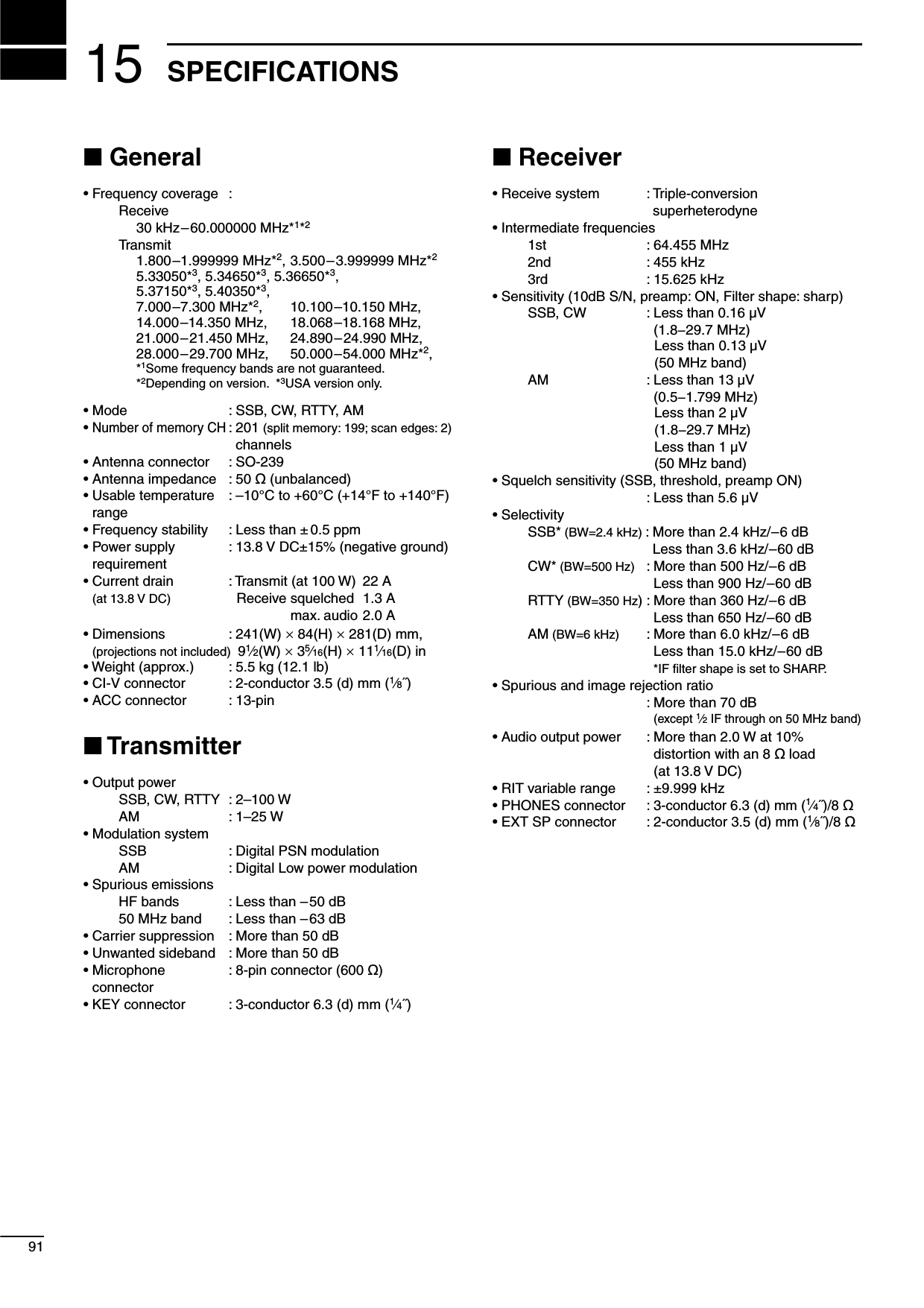
![1692OPTIONS123456789101112131415161718192021AT-180 HF/50 MHZ AUTOMATIC ANTENNA TUNERFully automatic antenna tuner with preset memories for each 100 kHz. Unique “automatic tuner on” func-tion is available. See p. 68 for AT-180 specifications.AH-4 HF AUTOMATIC ANTENNA TUNERSpecially designed to tune a long wire antenna for portable or mobile HF/50 MHz operation. The “PTT tune” func-tion provides simple operation.• Input power rating: 150 WAH-2b ANTENNA ELEMENTA 2.5 m long antenna ele-ment for mobile operation with the AH-4.• Frequency coverage 7–54 MHz band with the AH-4SM-20 DESKTOP MICROPHONEIncludes [UP]/[DOWN] switches and a low cut function.CT-17 CI-V LEVEL CONVERTER UNITFor remote transceiver control using a personal computer equipped with an RS-232C port. You can change frequencies, operating mode, memory channels, etc., via your computer.SP-10 EXTERNAL SPEAKERExternal speakers suitable for mobile operation.SP-10: Compact-type; 4 ø/5 WSP-21 EXTERNAL SPEAKERDesigned for base station operation.• Input impedance: 8 ø• Max. input power: 5 WHM-36 HAND MICROPHONEHand microphone equipped with [UP]/[DOWN] switches.SP-20 EXTERNAL SPEAKER4 audio filters; headphone jack; can connect to 2 transceivers.• Input impedance: 8 ø• Max. input power: 5 WMB-116 HANDLEConvenient when moving the trans-ceiver and provides front panel pro-tection during transport.MB-117 CARRYING HANDLEConvenient when carrying the trans-ceiver.MB-118 MOBILE NOUNTING BRACKETFor mounting the transceiver in a ve-hicle.](https://usermanual.wiki/ICOM-orporated/301500/User-Guide-977157-Page-97.png)