ICOM orporated 301500 HF/50 MHz Transceiver User Manual IC 718 Instruction Manual
ICOM Incorporated HF/50 MHz Transceiver IC 718 Instruction Manual
User Manual
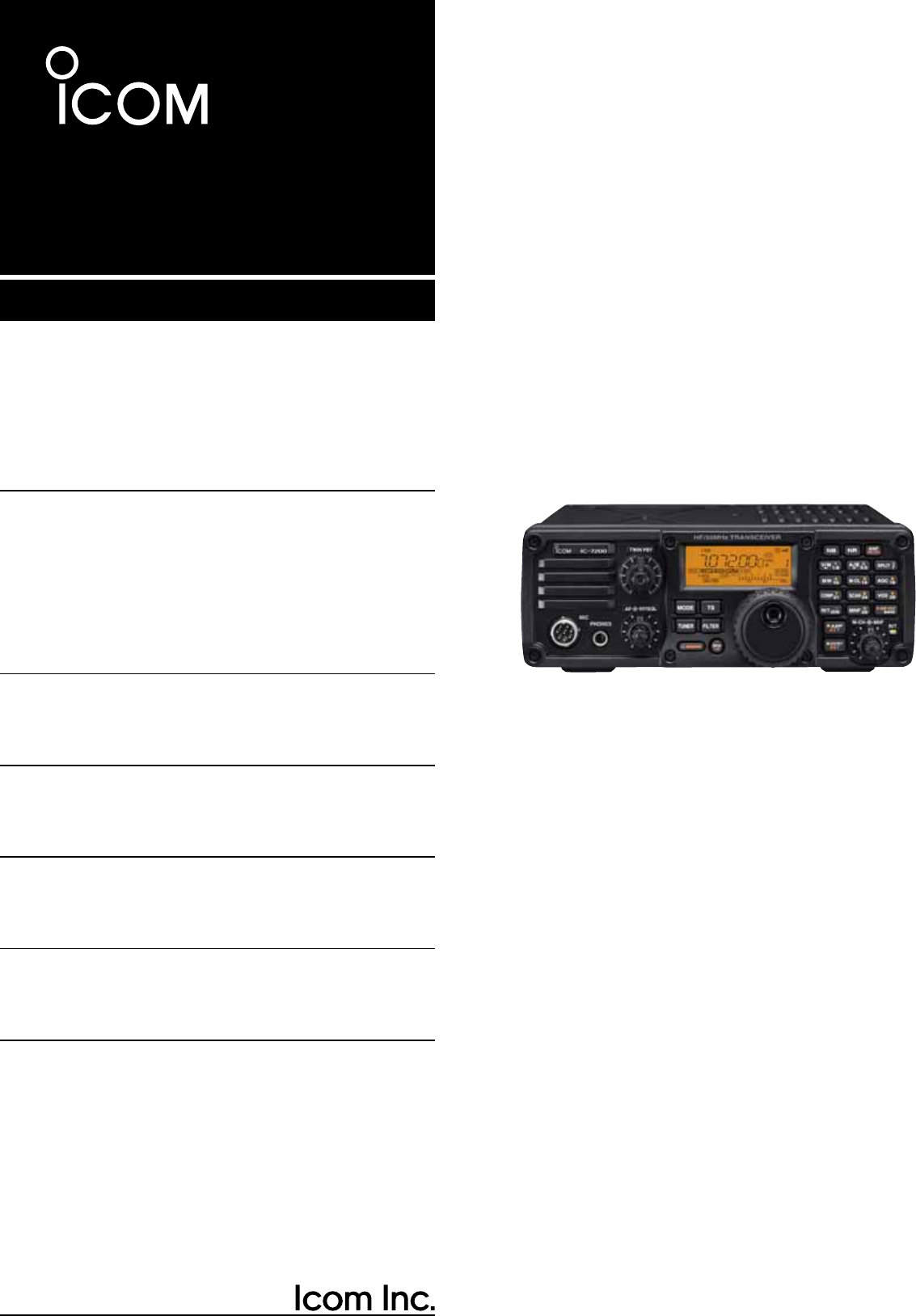
INSTRUCTION MANUAL
HF/50 MHz TRANSCEIVER
i7200
IMPORTANT
READ THIS INSTRUCTION MANUAL
CAREFULLY before attempting to operate the
transceiver.
SAVE THIS INSTRUCTION MANUAL. This
manual contains important safety and operating in-
structions for the IC-7200.
FOREWORD
We understand that you have a choice of many differ-
ent radios in the market place. We want to take a cou-
ple of moments of your time to thank you for making
the IC-7200 your radio of choice, and hope you agree
with Icom’s philosophy of “technology first.” Many
hours of research and development went into the de-
sign of your IC-7200.
D
FEATURES
M IF DSP features
M Digital Twin PBT
M Manual notch function
M ±0.5 ppm of high frequency stability
M Simple operation
M Tough and compact body
M Standard voice synthesizer
EXPLICIT DEFINITIONS
WORD DEFINITION
RWARNING Personal injury, fire hazard or electric
shock may occur.
CAUTION Equipment damage may occur.
NOTE
If disregarded, inconvenience only. No risk
of personal injury, fire or electric shock.
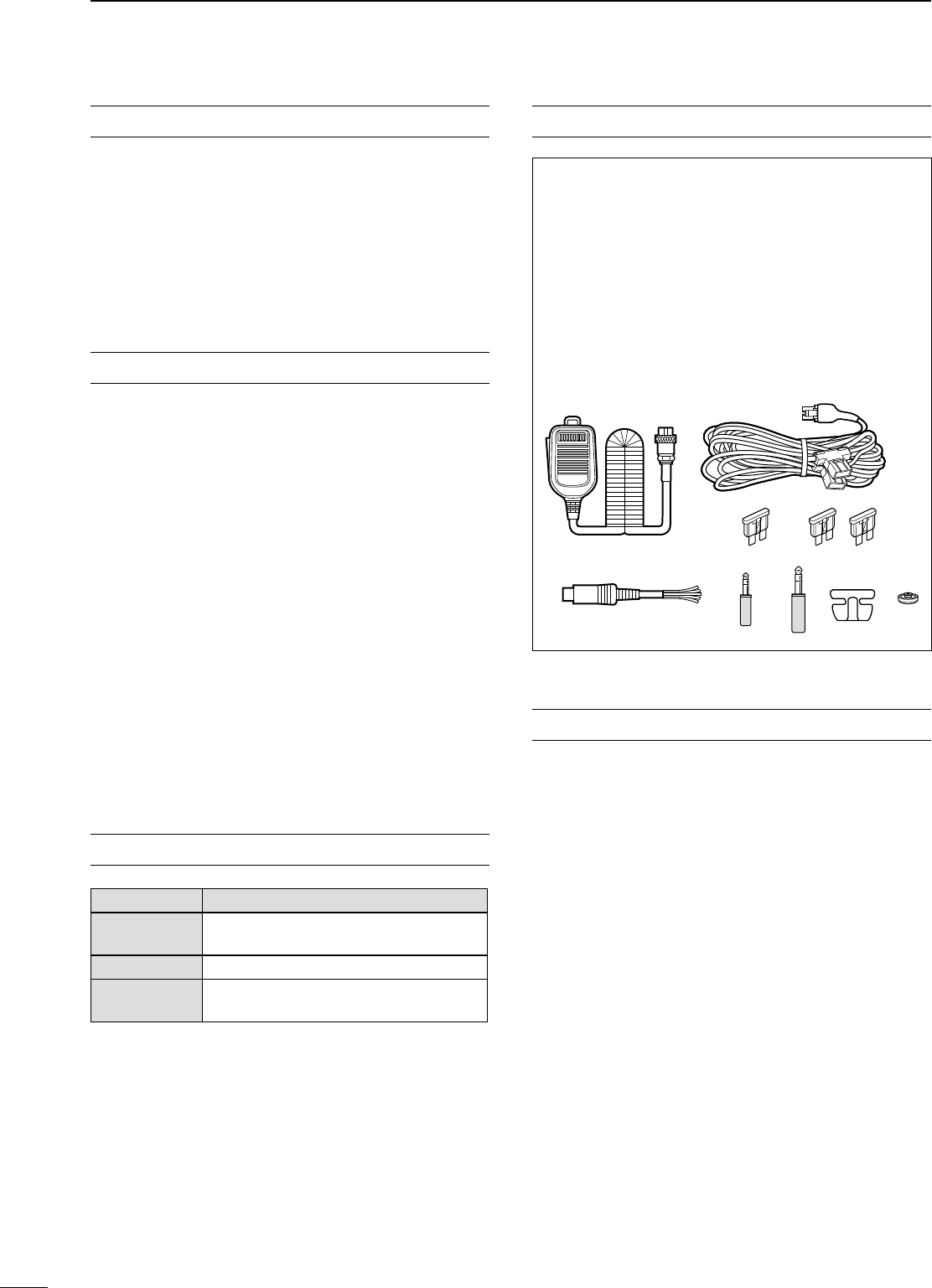
SUPPLIED ACCESSORIES
The transceiver comes with the following accessories.
Qty.
q Hand microphone (HM-36) ............................. 1
w DC power cable (OPC-1457) .......................... 1
e Spare fuse (ATC 5 A) ...................................... 1
r Spare fuse (ATC 30 A) .................................... 2
t ACC cable ......................................................... 1
y 3.5 (d) mm plug ................................................. 1
u 6.3 (d) mm Electronic keyer plug ...................... 1
i Microphone hanger ........................................... 1
o Jack cap (for [PHONES]) ................................. 1
q
e
t
w
yu
r
io
FCC INFORMATION
• FOR CLASS B UNINTENTIONAL RADIATORS:
This equipment has been tested and found to comply
with the limits for a Class B digital device, pursuant to
part 15 of the FCC Rules. These limits are designed
to provide reasonable protection against harmful in-
terference in a residential installation. This equipment
generates, uses and can radiate radio frequency en-
ergy and, if not installed and used in accordance with
the instructions, may cause harmful interference to
radio communications. However, there is no guaran-
tee that interference will not occur in a particular in-
stallation. If this equipment does cause harmful inter-
ference to radio or television reception, which can be
determined by turning the equipment off and on, the
user is encouraged to try to correct the interference
by one or more of the following measures:
• Reorient or relocate the receiving antenna.
• Increase the separation between the equipment
and receiver.
• Connect the equipment into an outlet on a circuit
different from that to which the receiver is con-
nected.
• Consult the dealer or an experienced radio/TV
technician for help.
i

PRECAUTIONS
R WARNING RF EXPOSURE! This device emits
Radio Frequency (RF) energy. Extreme caution
should be observed when operating this device. If
you have any questions regarding RF exposure and
safety standards please refer to the Federal Com-
munications Commission Office of Engineering and
Technology’s report on Evaluating Compliance with
FCC Guidelines for Human Radio Frequency Electro-
magnetic Fields (OET Bulletin 65).
R WARNING HIGH VOLTAGE! NEVER touch an
antenna or internal antenna connector during trans-
mission. This may result in an electrical shock or burn.
R WARNING! NEVER operate the transceiver
while driving a vehicle. Safe driving requires your full
attention—anything less may result in an accident.
R NEVER apply AC power to the [DC13.8V] socket
on the transceiver rear panel. This could cause a fire
or damage the transceiver.
R NEVER apply more than 16 V DC, such as a 24 V
battery, to the [DC13.8V] socket on the transceiver
rear panel. This could cause a fire or damage the
transceiver.
R NEVER let metal, wire or other objects touch any
internal part or connectors on the rear panel of the
transceiver. This may result in an electric shock or this
could cause a fire or damege the transceiver.
R NEVER expose the transceiver to rain, snow or
any liquids.
DO NOT use or place the transceiver in areas with
temperatures below –10°C (+14°F) or above +60°C
(+140°F). Be aware that temperatures on a vehicle’s
dashboard can exceed +80°C (+176°F), resulting in
permanent damage to the transceiver if left there for
extended periods.
DO NOT place the transceiver in excessively dusty
environments or in direct sunlight.
DO NOT place the transceiver against walls or put
anything on top of the transceiver. This will obstruct
heat dissipation.
Place unit in a secure place to avoid inadvertent use
by children.
During mobile operation, NEVER place the trans-
ceiver where air bag deployment may be obstructed.
During mobile operation, DO NOT place the trans-
ceiver where hot or cold air blows directly onto it.
During mobile operation, DO NOT operate the trans-
ceiver without running the vehicle’s engine. When the
transceiver’s power is ON and your vehicle’s engine
is OFF, the vehicle’s battery will quickly become ex-
hausted.
Make sure the transceiver power is OFF before start-
ing the vehicle engine. This will avoid possible dam-
age to the transceiver by ignition voltage spikes.
During maritime mobile operation, keep the trans-
ceiver and microphone as far away as possible from
the magnetic navigation compass to prevent errone-
ous indications.
BE CAREFUL! The rear panel will become hot when
operating the transceiver continuously for long peri-
ods.
BE CAREFUL! If a linear amplifier is connected, set
the transceiver’s RF output power to less than the
linear amplifier’s maximum input level, otherwise, the
linear amplifier will be damaged.
Use Icom microphones only (supplied or optional).
Other manufacturer’s microphones have different pin
assignments, and connection to the IC-7200 may
damage the transceiver.
For U.S.A. only
Caution: Changes or modifications to this trans-
ceiver, not expressly approved by Icom Inc., could
void your authority to operate this transceiver under
FCC regulations.
Icom, Icom Inc. and the logo are registered trademarks of
Icom Incorporated (Japan) in the United States, the United King-
dom, Germany, France, Spain, Russia and/or other countries.
ii

iii
TABLE OF CONTENTS
IMPORTANT ............................................................... i
FOREWORD .............................................................. i
EXPLICIT DEFINITIONS ............................................ i
SUPPLIED ACCESSORIES....................................... i
FCC INFORMATION .................................................. i
PRECAUTIONS ......................................................... ii
TABLE OF CONTENTS ........................................... iv
1 PANEL DESCRIPTION................................... 1−11
N
Front panel ........................................................ 1
D Keypad .......................................................... 5
N
Function display ................................................ 7
N
Rear panel ......................................................... 9
D ACC socket information .............................. 10
N
Microphones .................................................... 11
D HM-36 ......................................................... 11
D SM-20 ......................................................... 11
2 INSTALLATION AND CONNECTIONS ........ 12−20
N
Unpacking ....................................................... 12
N
Selecting a location ......................................... 12
N
Grounding ....................................................... 12
N
Antenna connection ........................................ 12
N
Required connections...................................... 13
N
Advanced connections .................................... 14
N
Power supply connections ............................... 15
N
Connecting the DC Power Supply ................... 15
N
Battery connections ......................................... 15
N
External antenna tuners .................................. 16
N
Linear amplifier connections............................ 17
NConnections for CW ........................................ 18
NConnections for RTTY ..................................... 19
D Connections for RTTY (FSK) ...................... 19
D Connections for RTTY (AFSK) .................... 19
NConnections for SSTV or PSK31 .................... 20
D When connecting to the [ACC] socket ......... 20
D When connecting to the [MIC] connector .... 20
3 BASIC OPERATION ..................................... 21−32
N When first applying power (CPU resetting) ..... 21
N Initial settings .................................................. 21
N VFO description ............................................... 22
N VFO operation ................................................. 22
D Selecting the VFO A/B ................................ 22
D VFO equalization ......................................... 22
N Selecting VFO/memory mode ......................... 23
D Differences between VFO mode and
memory mode ............................................. 23
N Selecting an operating band ........................... 24
D Using the band stacking register ................. 24
N Frequency setting ............................................ 25
D Using the main dial ..................................... 25
D Direct frequency entry with keypad ............. 25
D Programmable tuning steps ........................ 26
D Selecting the programmable tuning step..... 26
D 1 Hz and 10 Hz tuning steps ....................... 27
D TS switch flow chart ................................. 27
D Auto tuning step function ............................ 28
D ¼ tuning function
(SSB data/AM data/CW/RTTY only) ........... 28
D Band edge warning beep ............................ 28
N Volume setting ................................................. 29
N Operating mode selection ............................... 29
N Dial lock function ............................................. 29
N RF gain and Squelch ....................................... 30
N Meter function ................................................. 30
N Basic transmit operation .................................. 31
D Transmitting ................................................. 31
D
Output power and Microphone gain settings
.. 31
N Voice synthesizer function ............................... 32
4 RECEIVE AND TRANSMIT .......................... 33−43
N Operating SSB ................................................ 33
D Convenient functions for receive ................. 33
D Convenient functions for transmit ................ 34
D About 5 MHz band operation
(USA version only) ...................................... 34
N Operating CW ................................................. 35
D Convenient functions for receive ................. 36
D Convenient functions for transmit ................ 36
D CW reverse mode ....................................... 37
D CW pitch control .......................................... 37
D CW side tone function ................................. 38
D Keying speed setting ................................... 38
NOperating RTTY (FSK) .................................... 39
D Convenient functions for receive ................. 39
D RTTY reverse mode .................................... 40
D Twin peak filter ............................................ 40
D RTTY decode set mode .............................. 41
N Operating AM .................................................. 42
D Convenient functions for receive ................. 42
D Convenient functions for transmit ................ 42
N Data mode (SSTV/PSK31) operation .............. 43

5 FUNCTIONS FOR RECEIVE ........................ 44−52
N RIT function ..................................................... 44
N Preamp and attenuator ................................... 45
N AGC function ................................................... 45
D AGC time constant selection ....................... 45
N Twin PBT operation ......................................... 46
N IF filter selection .............................................. 47
D IF filter selection .......................................... 47
D FIlter passband width setting ...................... 48
D IF fIlter shape (SSB/CW only) ..................... 48
N Noise blanker .................................................. 49
D Noise blanker settings ................................. 49
N Noise reduction ............................................... 50
D Noise reduction level setting ....................... 50
N Notch function ................................................. 51
D Auto notch function ..................................... 51
D Manual notch function ................................. 51
D Manual notch filter setting ........................... 52
6 FUNCTIONS FOR TRANSMIT ..................... 53−60
N VOX function .................................................... 53
D Adjusting the VOX function.......................... 53
D VOX set mode ............................................. 54
N Break-in function ............................................. 55
D Semi break-in operation .............................. 55
D Full break-in operation ................................ 56
N Speech compressor ........................................ 57
D Compression level setting ........................... 57
N Split frequency operation ................................ 58
D Quick split function ...................................... 59
D Split lock function ........................................ 59
NMeasuring SWR .............................................. 60
7 MEMORY OPERATION ................................ 61−64
N
Memory channels ............................................ 61
NMemory channel selection .............................. 61
NMemory programming ..................................... 62
D Programming in VFO mode ........................ 62
D Programming in memory mode ................... 62
NFrequency copying .......................................... 63
D Memory ¶ VFO ........................................... 63
NMemory clearing ............................................. 64
8 SCAN OPERATION ...................................... 65−66
N Scan types ...................................................... 65
N Preparation ...................................................... 65
N Programmed scan operation (VFO mode) ...... 66
N Memory scan operation (Memory mode) ........ 66
9 ANTENNA TUNER OPERATION ................. 67−69
N Optional AT-180 AUTOMATIC ANTENNA TUNER
operation ......................................................... 67
D Tuner operation ........................................... 67
D Manual tuning ............................................. 67
N AT-180 internal switch description ................... 68
N Optional AH-4 AUTOMATIC ANTENNA TUNER
operation ......................................................... 69
D AH-4 operation ............................................ 69
10 SET MODE ................................................... 70−82
N General ........................................................... 70
D Quick set mode operation ........................... 70
D Set mode operation ..................................... 70
N Quick set mode ............................................... 71
N Set mode ......................................................... 74
D Paddle operation from [MIC] connector ...... 82
11 MAINTENANCE ........................................... 83−84
N Fuse replacement ........................................... 83
D DC power cable fuse replacement .............. 83
D Circuitry fuse replacement .......................... 83
N Memory backup ............................................... 84
N Resetting the CPU .......................................... 84
N Cleaning .......................................................... 84
12 TROUBLESHOOTING .................................. 85−86
13 OPTION INSTALLATIONS ................................. 87
N MB-116 HANDLES installation ........................... 87
N MB-117 CARRYING HANDLE installation ............. 87
N
MB-118
MOBILE
MOUNTING
BRACKET
installation
.. 87
14 CONTROL COMMAND ................................ 88−90
N Remote jack (CI-V) information ....................... 88
D CI-V connection example ............................ 88
D Data format ................................................. 88
D Command table ........................................... 89
15 SPECIFICATIONS .............................................. 91
N General ........................................................... 91
N Transmitter ....................................................... 91
N Receiver .......................................................... 91
16 OPTIONS ...................................................... 92−93
17 ABOUT CE ................................................... 94−95
iv
1
2
3
4
5
6
7
8
9
10
11
12
13
14
15
16
17
18
19
20
21
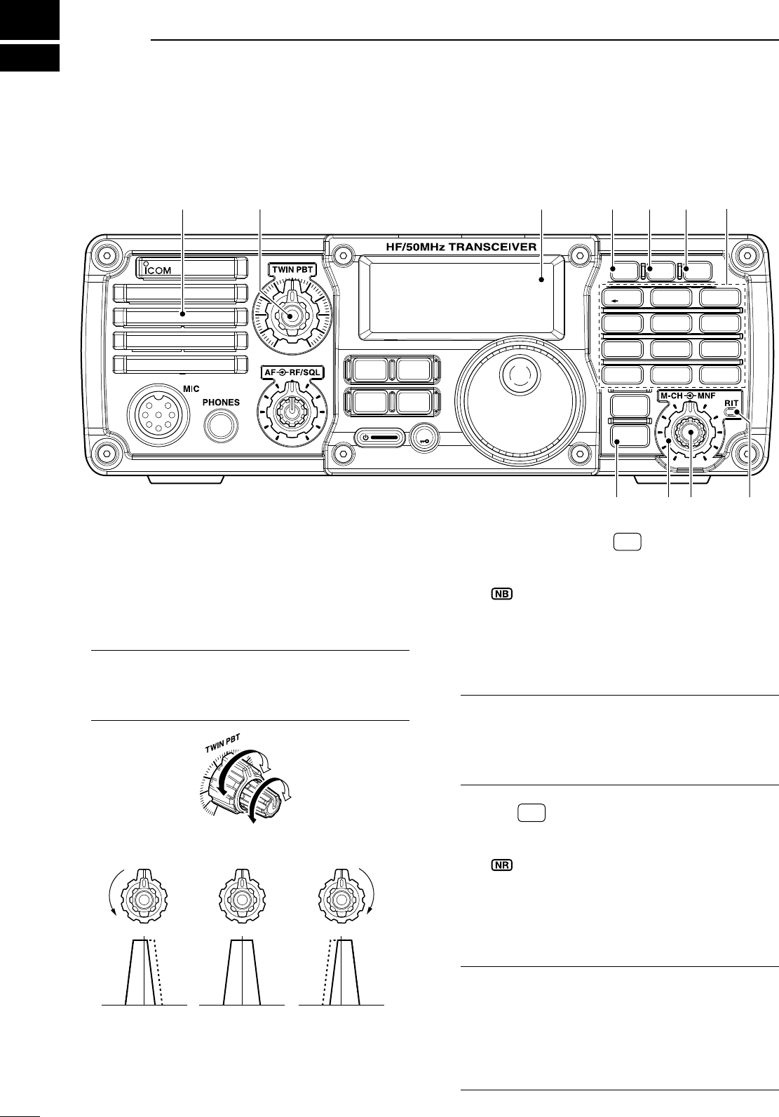
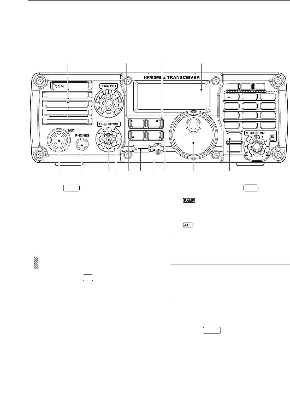
q PASSBAND TUNING CONTROLS [TWIN PBT]
Adjust the receiver’s DSP filter passband width.
(p. 46)
• The limit of the variable range depends on the pass-
band width and mode. The limit of the variable range
is half of the passband width, and PBT is adjustable in
25 Hz steps.
What is the PBT control?
Generally, the PBT electronically narrows the IF
passband width to reject interference. This trans-
ceiver uses the DSP circuit for the PBT function.
PBT2
PBT1
Low cutHigh cut Center
TWIN PBT TWIN PBT TWIN PBT
–+
w NOISE BLANKER KEY NB (p. 49)
± Push to turn the noise blanker function ON or
OFF.
• “ ” appears on the display.
± Push and hold for 1 sec to enter the noise
blanker set mode
; push again to return to normal
operation.
• Before entering the noise blanker set mode, the
noise blanker function is turned ON.
What is the noise blanker?
The noise blanker reduces pulse-type noise such
as that generated by automobile ignition systems.
This function is not effective against non pulse-type
noise.
e NR KEY NR (p. 50)
± Push to turn the noise reduction function ON or
OFF.
• “ ” appears on the display.
± Push and hold for 1 sec. to enter the noise re-
duction level set mode
; push again to return to
normal operation.
• Before entering the noise reduction set mode, the
noise reduction function is turned ON.
What is the Noise Reduction function?
The Noise Reduction (NR) function removes ran-
dom noise from the receiver passband. The level is
adjustable to allow maximum clarity without harm-
ing the intelligibility of the desired signal. Noise Re-
duction should generally not be used with digital
modes.
1
1
PANEL DESCRIPTION
i7200
MODE
TUNER
TS
FILTER
SPCH
V/M
A/B
SPLIT
M-CL
SCAN
SET
ATT
P
.
AMP
COMP
VOX
MNF
RIT
123
456
78
0
50
28
1814
10
21 24
=
7
3.51.8
F-INP
M-CH/RIT
ENT
BAND
GENE
9
.
AGC
MW
ANF
METER
NRNB
Speaker trew
Function
Display (p. 7)
uiy
q
o
N
Front panel
2
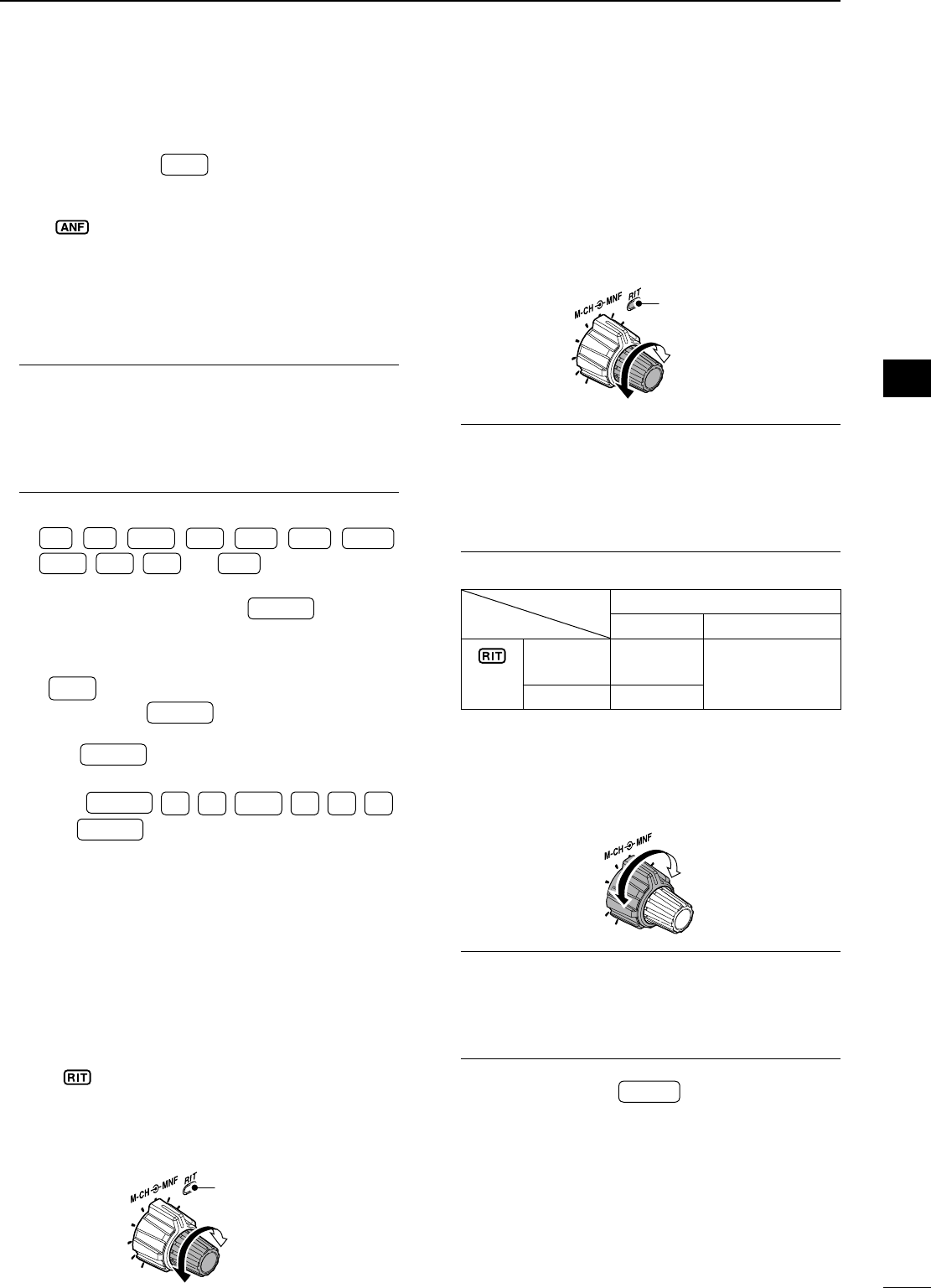
r ANF/METER KEY ANF
METER (p. 51)
±
Push to turn the Automatic Notch Filter function
ON or OFF in SSB and AM modes.
• “ ” appears on the display.
± Push and hold for 1 sec. to toggle the meter
function; (pgs. 30, 60)
PO « SWR « ALC
• PO : indicates the relative RF output power.
• SWR : indicates the SWR over the transmission line.
• ALC : Indicates ALC level.
What is the Automatic Notch Filter?
The Automatic Notch Filter is a narrow DSP filter that
automatically identifies and attenuates beat tones, tun-
ing signals, CW, etc., even if they are moving and re-
moves them from the receiver passband while pre-
serving the desired signal’s frequency response.
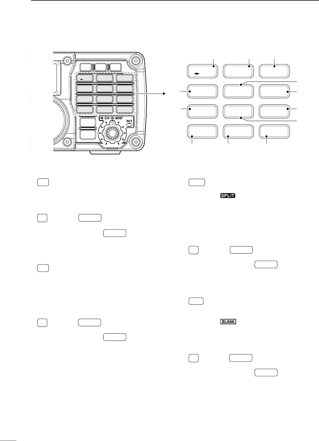
t KEYPAD
± V/M
,
A/B
=
,
SPLIT
,
MW
,
M-CL
,
AGC
,
COMP
,
SCAN
,
VOX
,
RIT
and
MNF
keys are available.
(p. 5)
± After pushing and holding F-INP ENT
BAND for 1 sec.,
push a key on the keypad to select the operating
band. (p. 24)
• The band stacking register is available.
• •
GENE selects the general coverage band.
± After pushing F-INP ENT
BAND , push a key on the key-
pad to enter a numeric frequency. After entering,
push F-INP ENT
BAND . (p. 25)
• e.g. To enter 14.195 MHz;
Push F-INP ENT
BAND , 1
1.8 , 4
10 , •
GENE , 1
1.8 , 9
28 , 5
14
and F-INP ENT
BAND .
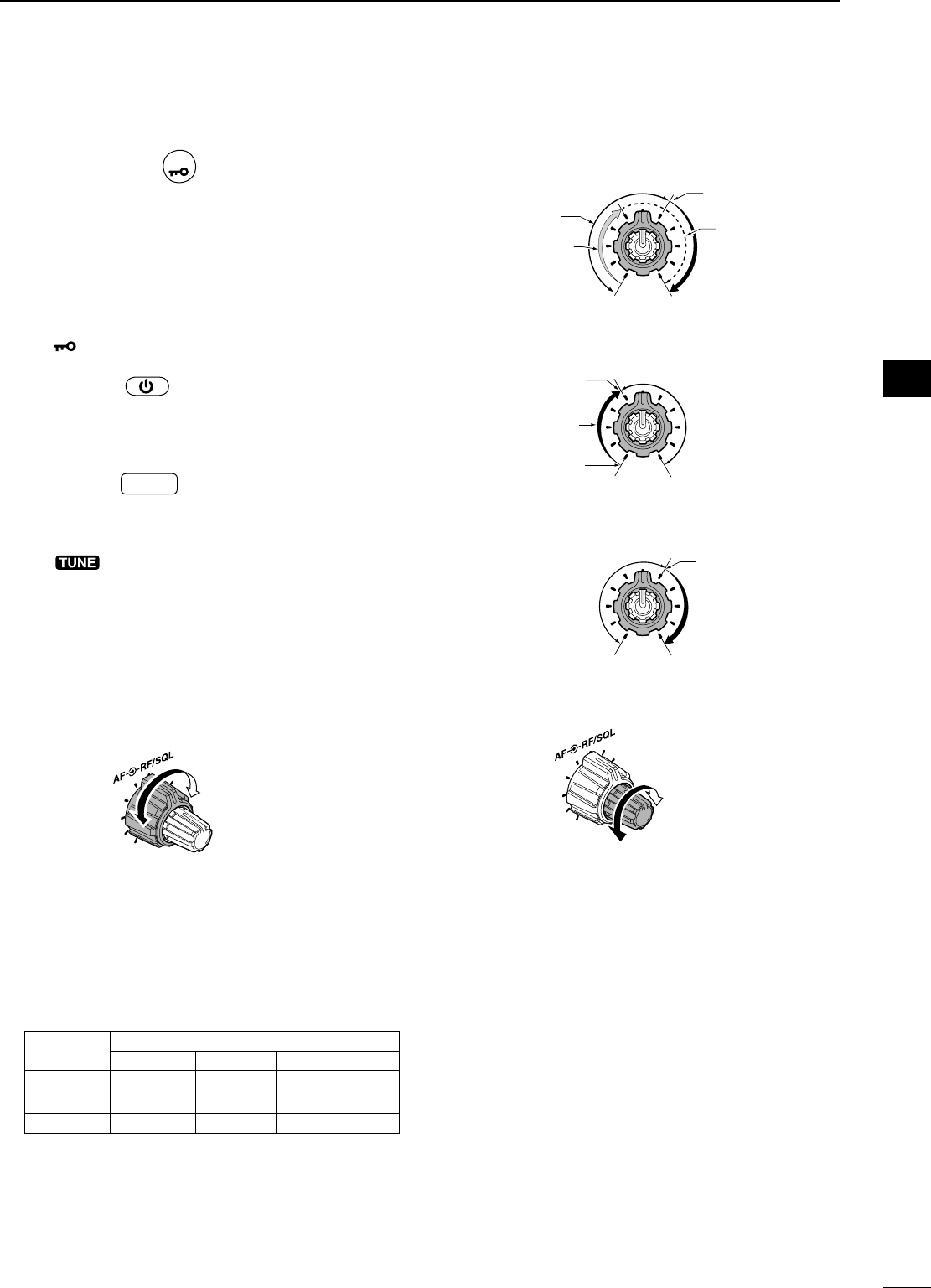
y RIT CONTROL INDICATOR (pgs. 44, 61)
Lights red when [M-CH] control (u) acts as the
RIT control.
u M-CH/RIT CONTROL [M-CH] (inner control)
± While in the set mode/quick set mode, rotate to
select the set mode item. (p. 70)
± This control can act as the memory channel
control or RIT control.
• The RIT function should be turned ON in advance to
activate this control as RIT control. (p. 44)
- “” appears when the RIT function is turned ON.
• The RIT control indicator (y) lights red when this
control is activated as the RIT control.
During [M-CH] acts as the M-CH control:
Rotate to select a memory channel (p. 61).
OFF
M-CH
Channel decreases
Channel increases
During [M-CH] acts as RIT control:
Rotate to shift the receive frequency (p. 44).
• Rotate the control clockwise to incerase the fre-
quency, or rotate the control counterclockwise to de-
crease the frequency.
• The shift frequency range is ±9.999 kHz in 1 Hz
steps (or ±9.99 kHz in 10 Hz steps).
Lights red
RIT
Frequency decreases
Frequency increases
What is the RIT function?
The RIT (Receiver Incremental Tuning) shifts the re-
ceive frequency without shifting the transmit frequency.
This is useful for fine tuning for stations calling you
off-frequency or when you prefer to listen to slightly
different sounding voice characteristics, etc.
• About the [M-CH] control activation:
RIT control indicator (y on p. 2)
Lights OFF
indicator
(!6 on p. 8)
Appears Acts as the
RIT control Acts as the mem-
ory channel control
Disappears N/A
i MANUAL NOTCH FILTER CONTROL [MNF]
(outer control; p. 51)
Rotate to adjust the notch filter frequency to reject
an interfering signal while the manual notch func-
tion is ON.
High frequency
Low frequency
What is the Manual Notch Filter?
The Manual Notch Filter is an adjustable narrow
DSP filter that removes tones from CW, SSB or AM
signals while preserving the desired signal’s fre-
quency response.
o M-CH/RIT•SET KEY M-CH/RIT
SET
± Push to set the [M-CH] control to RIT control.
•
The RIT function should be turned ON in advance. (p. 44)
• The RIT control indicator (y) lights red when the
[M-CH] control functions as the RIT control.
± Push and hold for 1 sec. to enter the quick set
mode. (p. 70)
± During quick set mode, push and hold for 1 sec.
to enter the set mode (p. 70)
± During quick/set mode, push to return to normal
operation. (p. 70)
1
PANEL DESCRIPTION
1
2
3
4
5
6
7
8
9
10
11
12
13
14
15
16
17
18
19
20
21
3
!0 MODE KEY MODE (p. 29)
± Push momentarily to cycle through the operating
modes:
USB/LSB « CW/CW-R « RTTY/RTTY-R « AM
± Push and hold for 1 sec. to toggle the following
operating modes:
USB ¢ LSB (p. 33)
CW ¢ CW-R (Reverse) (p. 35)
RTTY ¢ RTTY-R (Reverse) (p. 39)
• “CW-R” or “RTTY-R” appears on the display when
reverse mode is selected.
Undesired modes can be inhibited in set mode.
(p. 81)
!1 TUNING STEP KEY TS (pgs. 26, 27)
± Push to turn the programmable tuning step ON
or OFF.
• “√” appears above the 1 kHz indicator when the pro-
grammable tuning step is turned ON and the fre-
quency can be changed in programmed kHz steps.
±
While the
programmable
tuning step is turned
ON (
“√” appears
), push and hold for 1 sec. to
enter tuning step set mode; push again to return
to normal operation.
• 0.1, 1, 5, 9 and 10 kHz programmable tuning steps
are available.
±
While the
programmable
tuning step is turned
OFF, push and hold for 1 sec. to turn the 1 Hz
step ON and OFF.
• 1 Hz indication appears, and the frequency can be
changed in 1 Hz steps.
!2 PREAMP/ATTENUATOR KEY P.AMP
ATT (p. 45)
± Push to turn the preamp ON or OFF.
• “ ” appears on the display.
± Push and hold for 1 sec. to turn the 20 dB atten-
uator ON; push momentarily to turn the attenua-
tor OFF.
• “ ” appears on the display.
What is the preamp?
The preamp amplifies signals in the receiver front
end (input) circuit to improve the sensitivity. Turn
the preamp ON when receiving weak signals.
What is the attenuator?
The attenuator prevents a strong undesired signal
near the desired frequency or near your location,
such as from a broadcast station, from causing dis-
tortion or spurious signals.
!3 MAIN DIAL [DIAL]
Changes the displayed frequency and selects val-
ues for selected set mode items, etc.
!4 FILTER KEY FILTER (p. 47)
± Push momentarily to cycle the IF filter settings
between wide, middle and narrow for the se-
lected operating mode.
± Push and hold for 1 sec. to enter the filter set
mode.
i7200
MODE
TUNER
TS
FILTER
SPCH
V/M
A/B
SPLIT
M-CL
SCAN
SET
ATT
P
.
AMP
COMP
VOX
MNF
RIT
123
456
78
0
50
28
1814
10
21 24
=
7
3.51.8
F-INP
M-CH/RIT
ENT
BAND
GENE
9
.
AGC
MW
ANF
METER
NRNB
Speaker
Function
Display (p. 7)
!3@1 !5 !4!6!7!9 !8@0
!1!0
!2
N
Front panel (Continued)
1PANEL DESCRIPTION
4
1
PANEL DESCRIPTION
1
2
3
4
5
6
7
8
9
10
11
12
13
14
15
16
17
18
19
20
21
!5 SPCH•LOCK KEY
SPCH
± Push to announce the selected frequency and
S-meter level by the speech synthesizer. (p. 32)
• The parameters to be announced can be selected in
the set mode. (p. 77)
± Push and hold for 1 sec. to turn the dial lock
function ON or OFF. (p. 29)
• The dial lock function electronically locks the main
dial.
• “ ” appears while the dial lock function is ON.
!6 POWER KEY
± Push to turn power ON.
• Turn the DC power supply ON in advance.
± Push and hold for 1 sec. to turn power OFF.
!7 TUNER KEY TUNER (p. 67)
± Push to turn the automatic antenna tuner func-
tion ON or OFF.
• An optional antenna tuner must be connected.
• “ ” appears on the display.
± Push and hold for 1 sec. to manually tune the
antenna tuner.
• An optional antenna tuner must be connected.
• When the tuner cannot tune the antenna, the tuning
circuit is bypassed automatically after 20 sec.
!8 RF GAIN/SQUELCH CONTROL [RF/SQL]
(outer control; p. 30)
± Adjusts the RF gain and squelch threshold level.
±
The squelch removes noise output from the
speaker (closed condition) when no signal is re-
ceived.
• The squelch is available for all modes.
• The control can be set as the squelch plus RF gain
controls, squelch control only (RF gain is fixed at
maximum) or Auto (RF gain control in SSB, CW and
RTTY; squelch control in AM) in set mode.
MODE SET MODE SETTING
AUTO SQL RF + SQL
SSB, CW
RTTY RF GAIN SQL RF GAIN + SQL
AM SQL SQL RF GAIN + SQL
Minimum RF gain
Adjustable range
RF gain adjustable
range
Maximum RF gain
Maximum RF gain
Squelch is open. S-meter squelch
S-meter squelch
threshold
Lowest threshold Highest threshold
Squelch is open.
S-meter squelch
S-meter squelch
threshold
• When functioning as RF GAIN/SQL control
• When functioning as RF GAIN control
(Squelch is fixed open; SSB, CW, RTTY only)
• When functioning as SQL control
(RF gain is fixed at maximum.)
!9 AF CONTROL [AF] (inner control; p. 29)
Varies the audio output level from the speaker.
Audio output
decreases
Audio output
increases
@0 HEADPHONE JACK [PHONES]
Accepts headphones with 8–16 Ω impedance.
• Output power: 5 mW with an 8 Ω load.
• When headphones are connected, no receive audio
comes from the speaker.
@1 MICROPHONE CONNECTOR [MIC]
Accepts supplied or optional microphone.
• See p. 11 for appropriate microphones and microphone
connector information.
5
1PANEL DESCRIPTION
@2
VFO/MEMORY/1/1.8 MHz BAND KEY
V/M
± Push to toggle the operating mode be-
tween VFO mode or memory mode.
(pgs. 23, 61)
± Push and hold for 1 sec. to copy the
memory contents to VFO.
(p. 63)
1
1.8 ± Push F-INP ENT
BAND , then push this key to in-
put the number ‘1.’
(p. 25)
± Push and hold F-INP ENT
BAND for 1 sec., then
push this key to select the 1.8 MHz band.
(p. 24)
@3
VFO SELECT/EQUALIZATION/2/3.5 MHz BAND KEY
A/B
=
± Push to toggle between VFO A and
VFO B.
(p. 22)
± Push and hold for 1 sec. to equalize the
frequency and operating mode of the two
VFO’s.
(p. 22)
•
The
undisplayed VFO
frequency and operat-
ing mode are set the same as the
displayed
VFO frequency and operating mode.
2
3.5 ± Push F-INP ENT
BAND , then push this key to in-
put the number ‘2.’
(p. 25)
± Push and hold F-INP ENT
BAND for 1 sec., then
push this key to select the 3.5 MHz band.
(p. 24)
@4 SPLIT/3/7 MHz BAND KEY
SPLIT ± Push to toggle the split function ON and
OFF. (p. 58)
• “ ” appears on the display.
±Push and hold for 1 sec. to activate the
quick split function. (p. 59)
•
The VFO B frequency and operating mode
are set the same as the VFO A frequency
and operating mode.
• The quick split function can be turned OFF
in the set mode. (p. 76)
3
7 ± Push F-INP ENT
BAND , then push this key to in-
put the number ‘3.’
(p. 25)
± Push and hold F-INP ENT
BAND for 1 sec., then
push this key to select the 7 MHz band.
(p. 24)
@5 MEMORY CLEAR/5/14 MHz BAND KEY
M-CL ± Push and hold for 1 sec. to clear the
displayed memory channel contents in
memory mode.
(p. 64)
• “” appears above the memory chan-
nel number.
± Push and hold for 1 sec., to select a
default condition or value when in set
mode/quick set mode.
(p. 70)
5
14 ± Push F-INP ENT
BAND , then push this key to in-
put the number ‘5.’
(p. 25)
± Push and hold F-INP ENT
BAND for 1 sec., then
push this key to select the 14 MHz band.
(p. 24)
V/M
A/B
SPLIT
M-CL
SCAN
SET
ATT
P
.
AMP
COMP
VOX
MNF
RIT
123
456
78
0
50
28
1814
10
21 24
=
7
3.5
1.8
F-INP
M-CH/RIT
ENT
BAND
GENE
9
.
AGC
MW
ANF
METER
NRNB
V/M
A/B
SPLIT
M-CL
SCANCOMP
VOX
MNF
RIT
123
456
78
0
50
28
1814
10
21 24
=
7
3.5
1.8
F-INP ENT
BAND
GENE
9
.
AGC
MW
@4@3@2
@7
@9
@8
@5
@6
#1 #0
#2
#3
D Keypad
6
1
PANEL DESCRIPTION
1
2
3
4
5
6
7
8
9
10
11
12
13
14
15
16
17
18
19
20
21
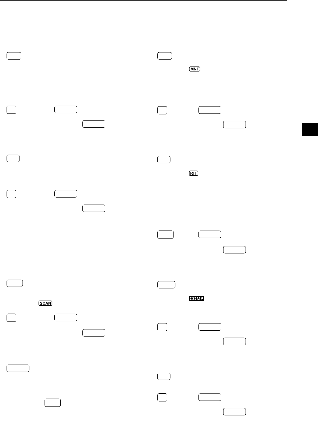
@6 AGC/6/18 MHz BAND KEY
AGC ± Push to toggle the time constant for
the AGC circuit fast and slow.
(p. 45)
• “F. AGC ” appears on the display when
fast AGC is selected; no indication ap-
pears when slow AGC is selected
± Push and hold for 1 sec. to turn the
AGC function OFF.
• “AGC-OFF” appears on the display.
6
18 ± Push F-INP ENT
BAND , then push this key to
input the number ‘6.’
(p. 25)
± Push and hold F-INP ENT
BAND for 1 sec.,
then push this key to select the 18
MHz band.
(p. 24)
@7 VOX/9/28 MHz BAND KEY
VOX ± Push to turn the VOX function ON or
OFF.
(p. 53)
± Push and hold for 1 sec. to enter VOX
set mode
; push again to return to nor-
mal operation.
9
28 ± Push F-INP ENT
BAND , then push this key to
input the number ‘9.’
(p. 25)
± Push and hold F-INP ENT
BAND for 1 sec.,
then push this key to select the 28
MHz band.
(p. 24)
What is the VOX function?
The VOX function (Voice-Operated Transmission)
activates the transmitter when you speak into the
microphone and automatically returns to receive
when you stop speaking.
@8 SCAN/8/24 MHz BAND KEY
SCAN Push to start/stop the programmed/
memory scan in VFO/memory mode.
(p. 66)
• “” appears on the display during
scanning.
8
24 ± Push F-INP ENT
BAND , then push this key to
input the number ‘8.’
(p. 25)
± Push and hold F-INP ENT
BAND for 1 sec.,
then push this key to select the 24
MHz band.
(p. 24)
@9 FREQUENCY INPUT/ENTER/BAND KEY
F-INP ENT
BAND ± Push to enter the direct frequency in-
put condition.
(p. 25)
± Push and hold for 1 sec., then push a
key on the keypad to select the oper-
ating band.
(p. 24)
• •
GENE selects the general coverage
band.
#0 MANUAL NOTCH FILTER/0/50 MHz BAND KEY
MNF ± Push to turn the manual notch filter func-
tion ON or OFF.
(p. 51)
• “ ” appears on the display.
± Push and hold for 1 sec. to enter the
manual notch set mode
; push again to
return to normal operation. (p. 51)
• Before entering the set mode, the manual
notch filter function is turned ON.
0
50 ± Push F-INP ENT
BAND , then push this key to in-
put the number ‘0.’
(p. 25)
± Push and hold F-INP ENT
BAND for 1 sec., then
push this key to select the 50 MHz band.
(p. 24)
#1 RIT/•/GENERAL BAND KEY
RIT ±
Push to turn the RIT (Receiver Incremen-
tal Tuning) function ON or OFF. (p. 44)
• “ ” appears on the display.
• RIT frequency can be adjusted with [M-CH]
control when RIT mode is selected.
± Push and hold for 1 sec. to add the RIT
shift frequency to the operating fre-
quency.
(p. 44)
• Available only when the XFC (transmit fre-
quency check function) is turned OFF.
(p. 76)
•
GENE ± Push F-INP ENT
BAND , then push this key to in-
put the number ‘• (decimal point).’
(p. 25)
± Push and hold F-INP ENT
BAND for 1 sec., then
push this key to select the general cover-
age band.
(p. 24)
#2 SPEECH COMPRESSOR/7/21 MHz BAND KEY
COMP ± Push to turn the speech compressor
function ON or OFF.
(p. 57)
• “ ” appears on the display.
± Push and hold for 1 sec. to enter the
speech compression level set mode
;
push again to return to normal operation.
7
21 ± Push F-INP ENT
BAND , then push this key to in-
put the number ‘7.’
(p. 25)
± Push and hold F-INP ENT
BAND for 1 sec., then
push this key to select the 21 MHz band.
(p. 24)
#3 MEMORY WRITE/4/10 MHz BAND KEY
MW Push and hold for 1 sec. to store the dis-
played VFO frequency and operating mode
into the selected memory channel. (p. 62)
4
10 ± Push F-INP ENT
BAND , then push this key to in-
put the number ‘4.’
(p. 25)
± Push and hold F-INP ENT
BAND for 1 sec., then
push this key to select the 10 MHz band.
(p. 24)
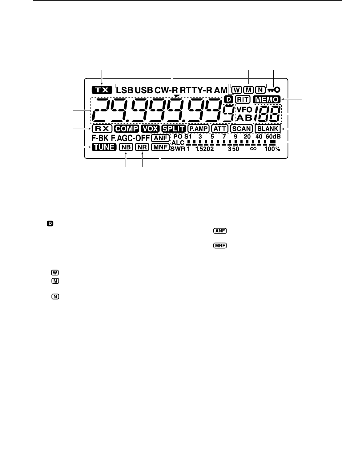
7
q TRANSMIT INDICATOR
Appears while transmitting.
w MODE INDICATORS
Shows the selected operating mode.
• “” appears when SSB/AM data mode is se-
lected. (p. 71)
• “-R” appears when CW reverse or RTTY reverse
mode is selected. (pgs. 29, 35, 39)
e IF FILTER INDICATORS (p. 47)
Shows the selected IF filter.
± “ ” appears when the wide IF filter is selected.
± “” appears when the normal IF filter is se-
lected.
± “” appears when the narrow IF filter is se-
lected.
r LOCK INDICATOR (p. 29)
Appears when the dial lock function is activated.
t MEMORY INDICATOR (p. 61)
Appears when memory mode is selected.
y MEMORY CHANNEL NUMBER READOUT
(p. 61)
Shows the selected memory channel number.
u BLANK INDICATOR (p. 62)
Appears when the selected memory channel is
blank.
• This indicator appears both in VFO and memory mode.
i SIGNAL/SQL/RF-GAIN METER
± Shows receiving signal strength while receiving.
± Shows either transmit power meter (Po), SWR
or ALC while transmitting. (p. 30)
o NOTCH INDICATORS (p. 51)
± “” appears when the automatic notch func-
tion is activated.
± “” appears when the manual notch function
is activated.
!0 NOISE REDUCTION INDICATOR (p. 50)
Appears when the noise reduction is activated.
!1 NOISE BLANKER INDICATOR (p. 49)
Appears when the noise blanker is activated.
!2 TUNE INDICATOR (p. 67)
± Appears when the optional automatic antenna
tuner is activated.
± Blinks while tuning.
!3 RECEIVE INDICATOR
Appears while receiving a signal or when the
squelch is open.
!4 FREQUENCY READOUT
Shows the operating frequency.
N
Function display
qw er
t
i
u
y
!1 o!0
!2
!3
!4
1PANEL DESCRIPTION
8
1
PANEL DESCRIPTION
1
2
3
4
5
6
7
8
9
10
11
12
13
14
15
16
17
18
19
20
21
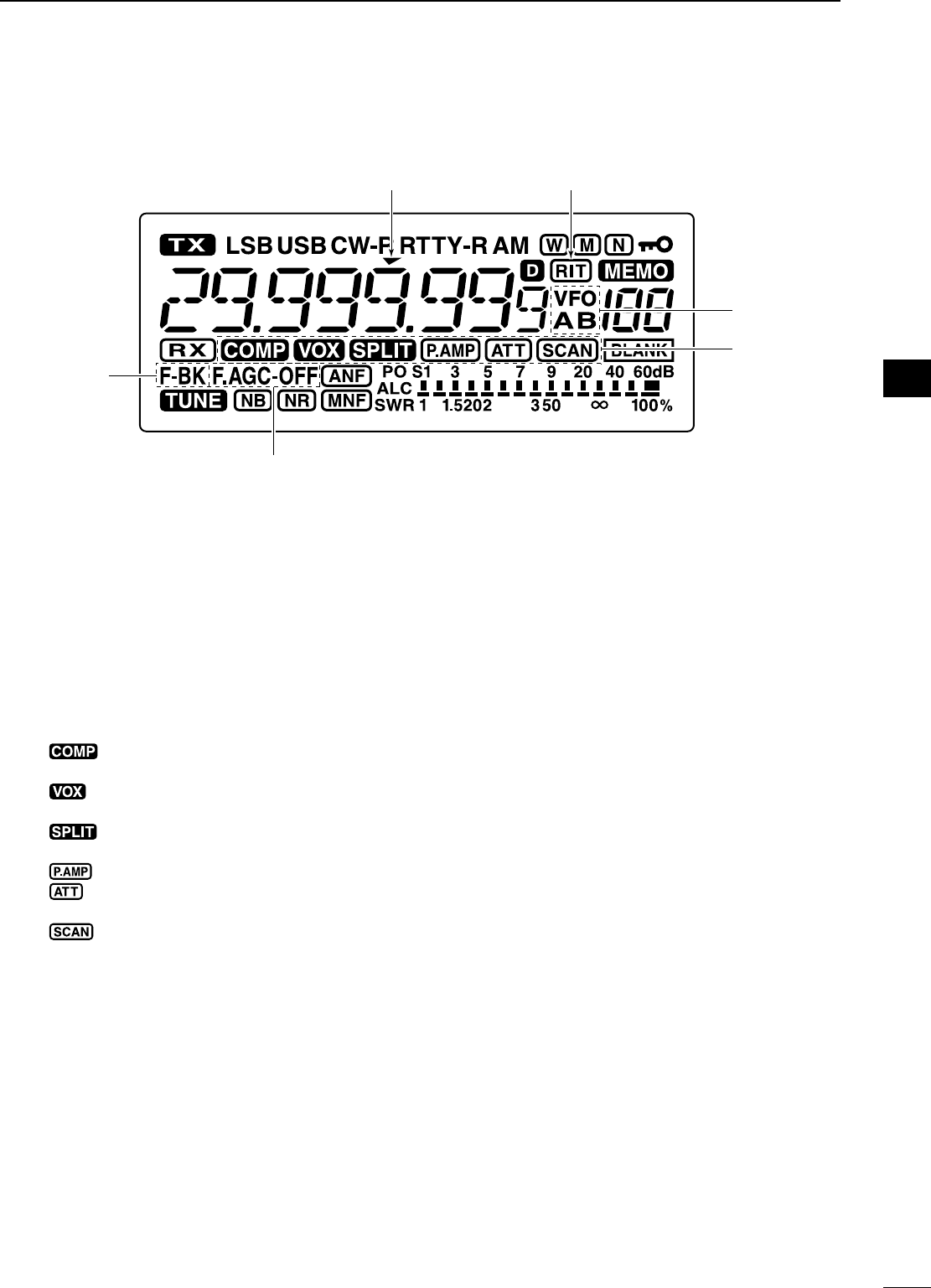
!5 PROGRAMMABLE TUNING STEP INDICATOR
Appears when the programmable tuning step is
selected. (p. 26)
!6 RIT INDICATOR (p. 44)
Appears when the RIT function is activated.
!7 VFO INDICATORS (p. 22)
“VFO A” or “VFO B” appears when VFO mode is
selected.
!8 FUNCTION INDICATORS
± “” appears when the speech compressor
is activated in SSB mode.
± “” appears when the VOX function is acti-
vated.
± “” appears during split frequency opera-
tion.
± “” appears when preamp is activated.
± “” appears when the attenuator function is
activated.
± “” appears during scan.
• Blinks when scan is paused.
!9 AGC INDICATORS (p. 45)
Shows the selected AGC time constant.
• “F.AGC” for AGC fast; “AGC-OFF” for AGC OFF; no in-
dicator; for AGC slow.
@0 BREAK-IN INDICATORS (p. 55)
± “BK” appears when the semi break-in function is
activated.
± “F-BK” appears when the full break-in function
is activated.
!5 !6
!7
!8
!9
@0
9
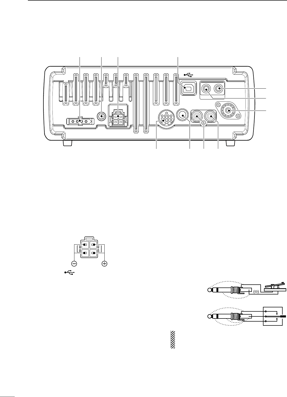
q TUNER CONTROL SOCKET [TUNER] (p. 16)
Accepts the control cable from an optional AH-4
HF/50 MHz AUTOMATIC ANTENNA TUNER
w GROUND TERMINAL [GND] (p. 12)
Connect this terminal to a ground to prevent elec-
trical shocks, TVI, BCI and other problems.
e DC POWER SOCKET [DC 13.8V] (p. 15)
Accepts 13.8 V DC through the supplied DC power
cable.
Rear panel view
r USB JACK [ ]
Connect the USB cable to be used for the modula-
tion input (p. 77), the transceiver operation with PC
(available in the near future), etc.
t EXTERNAL SPEAKER JACK [EXT SP] (p. 91)
Connect a 4–8 ø external speaker, if desired.
• When an external speaker is connected, the internal
speaker does not function.
y CI-V REMOTE CONTROL JACK [REMOTE] (p. 88)
± Designed for use with a PC for remote control of
the transceiver functions.
± Used for transceiver operation with another
Icom CI-V transceiver or receiver.
u ANTENNA CONNECTOR [ANT] (p. 13)
Accepts a 50 Ω antenna with a PL-259 connector
and a 50 Ω coaxial cable.
i ALC INPUT JACK [ALC] (p. 17)
Connects to the ALC output jack of a non-Icom lin-
ear amplifier.
o SEND CONTROL JACK [SEND] (p. 17)
Goes to ground while transmitting to control exter-
nal equipment such as a linear amplifier.
• Max. control level: 16 V DC/0.5 A
!0 ELECTRONIC KEYER JACK [KEY]
Accepts a key or paddle connector for the internal
electronic keyer.
• The keyer type selection between the internal elec-
tronic keyer and straight key operation can be made in
set mode.
When connecting
a straight key
When connecting
a paddle
(dot)
(com)
(dash)
()
If you use an external electronic keyer, make
sure the output voltage of the keyer is less than
0.4 V when keying the transmitter.
!1 ACCESSORY SOCKET [ACC] (p. 10)
Enables connection to external equipment such as
a TNC for data communications, a linear amplifier
or an automatic antenna tuner, etc.
• See page 10 for socket wiring information.
DC 13.8V ACC KEY SEND ALC ANT
REMOTE EXT SP
GNDTUNER
qwe r
t
y
u
io!
0
!
1
N
Rear panel
1PANEL DESCRIPTION
10
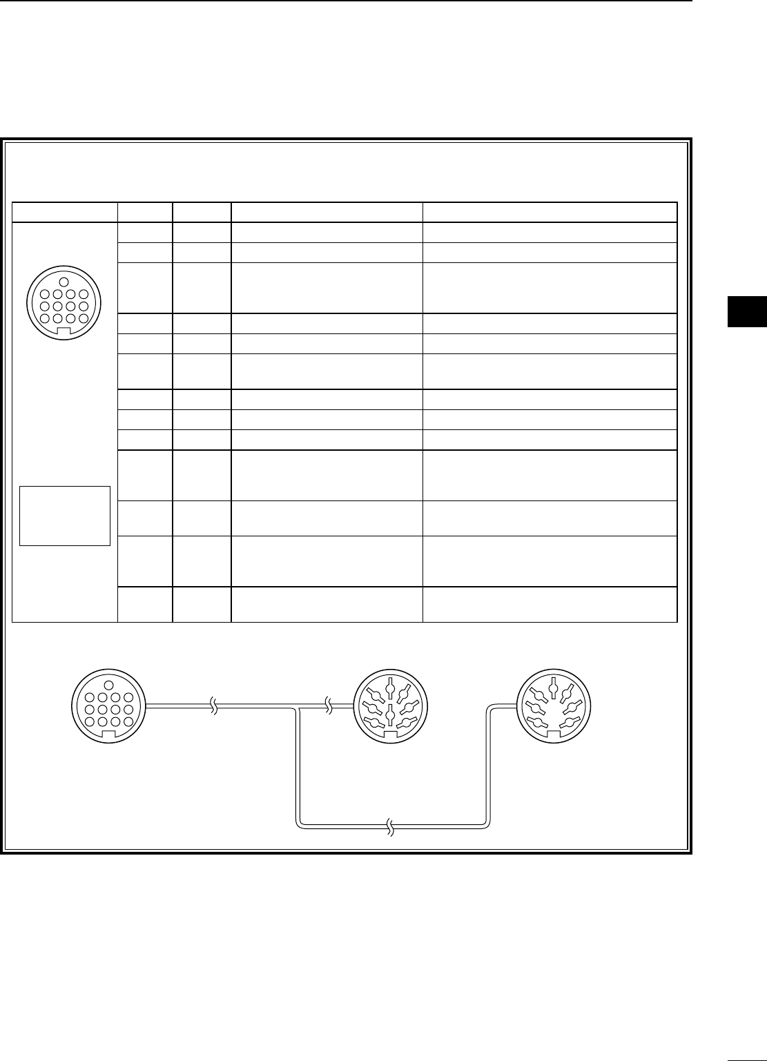
D ACC socket information
• ACC socket
ACC
PIN No.
NAME DESCRIPTION SPECIFICATIONS
1234
8765
9
10 11 12
13
Rear panel view
Color refers to
the cable strands
of the supplied
cable.
q brown
w red
e orange
r yellow
t green
y blue
u purple
i
o
!0
!1
!2
!3
gray
white
black
pink
light
blue
light
green
1 NC ——— ———
2 GND Connects to ground. ———
3
HSEND
Input/output pin.
Grounded when transmits.
Ground level
Output current
Input current (Tx)
: –0.5 V to 0.8 V
: Less than 20 mA
: Less than 200 mA
4 BDT Data line for the optional AT-180. ———
5 NC ——— ———
6 ALC ALC voltage input. Control voltage
Input impedance
: –4 V to 0 V
: More than 10 k˘
7 NC ——— ———
8 13.8 V 13.8 V output when power is ON. Output current : Max. 1 A
9 TKEY Key line for the optional AT-180. ———
10 FSKK Controls RTTY keying
“High” level
“Low” level
Output current
: More than 2.4 V
: Less than 0.6 V
: Less than 2 mA
11 MOD Modulator input. Input impedance
Input level
: 10 k˘
: Approx. 100 mV rms
12 AF
AF detector output.
Fixed level, regardless of the
[AF] control position
.
Output impedance
Output level
: 4.7 k˘
: 100–300 mV rms
13 SQLS Squelch output.
Grounded when squelch opens.
SQL open
SQL closed
: Less than 0.3 V/5 mA
: More than 6.0 V/100 μA
• When connecting the ACC conversion cable (OPC-599)
ACC 1 ACC 2
q FSKK t AF
w GND y SQLS
e SEND u 13.8 V
r MOD i ALC
q NC t ALC
w GND y SEND
e SEND u 13.8 V
r NC
1234
88
765
9
10 11 12
13
1
2
3
4
7
6
5
1
2
3
4
7
6
5
Connect to ACC socket
1
PANEL DESCRIPTION
1
2
3
4
5
6
7
8
9
10
11
12
13
14
15
16
17
18
19
20
21
11
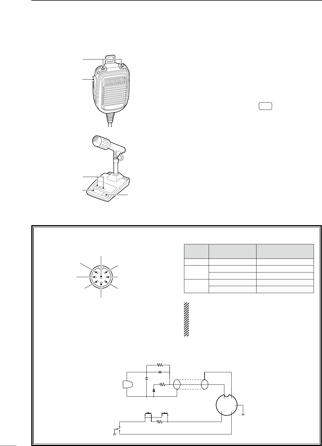
• MICROPHONE CONNECTOR
(Front view)
y GND (PTT ground)
t PTT
r Squelch switch
q Microphone input
w +8 V DC output
e Frequency up/down
i AF output
(varies with [AF])
u GND
(Microphone ground)
[MIC]
PIN NO. FUNCTION DESCRIPTION
w+8 V DC output Max. 10 mA
eFrequency up Ground
Frequency down Ground through 470 ˘
rSquelch open “LOW” level
Squelch close “HIGH” level
CAUTION: DO NOT short pin 2 to ground as
this can damage the internal 8 V regulator. DC
voltage is applied to pin 1 for microphone opera-
tion. Use caution when using a non-Icom micro-
phone.
• HM-36 SCHEMATIC DIAGRAM
+
q
w
ert
y
u
i
4700pF
0.33μF
MICROPHONE
MIC
ELEMENT
2kø
470ø
DOWN UP
PTT RECEIVE
TRANSMIT
MICROPHONE CABLE MICROPHONE PLUG
1kø
+
10μF
q UP/DOWN SWITCHES [UP]/[DN]
Change the selected readout frequency or memory
channel.
• Pushing the switch continuously changes the frequency
or memory channel number continuously.
• The [UP]/[DN] switch can simulate a key paddle. Select
in set mode (U/D KEY; Mic Up/Down Keyer). (p. 80)
• While pushing and holding RIT *, push the [UP]/[DN]
switch to control the transmit readout frequency while
in spilt frequency operation.
* Available only when the XFC (transmit frequency
check) function is turned ON. (p. 76)
w PTT SWITCH
Push and hold to transmit; release to receive.
e PTT LOCK SWITCH (SM-20 only)
Push to lock the PTT switch to the transmission
codition.
q
w
q
we
N
Microphones
D HM-36
D SM-20
(Option)
1PANEL DESCRIPTION
2
12
INSTALLATION AND CONNECTIONS
1
2
3
4
5
6
7
8
9
10
11
12
13
14
15
16
17
18
19
20
21
N
Unpacking
After unpacking, immediately report any damage to
the delivering carrier or dealer. Keep the shipping car-
tons.
For a description and a diagram of accessory equip-
ment included with the IC-7200, see ‘Supplied acces-
sories’ on p. i of this manual.
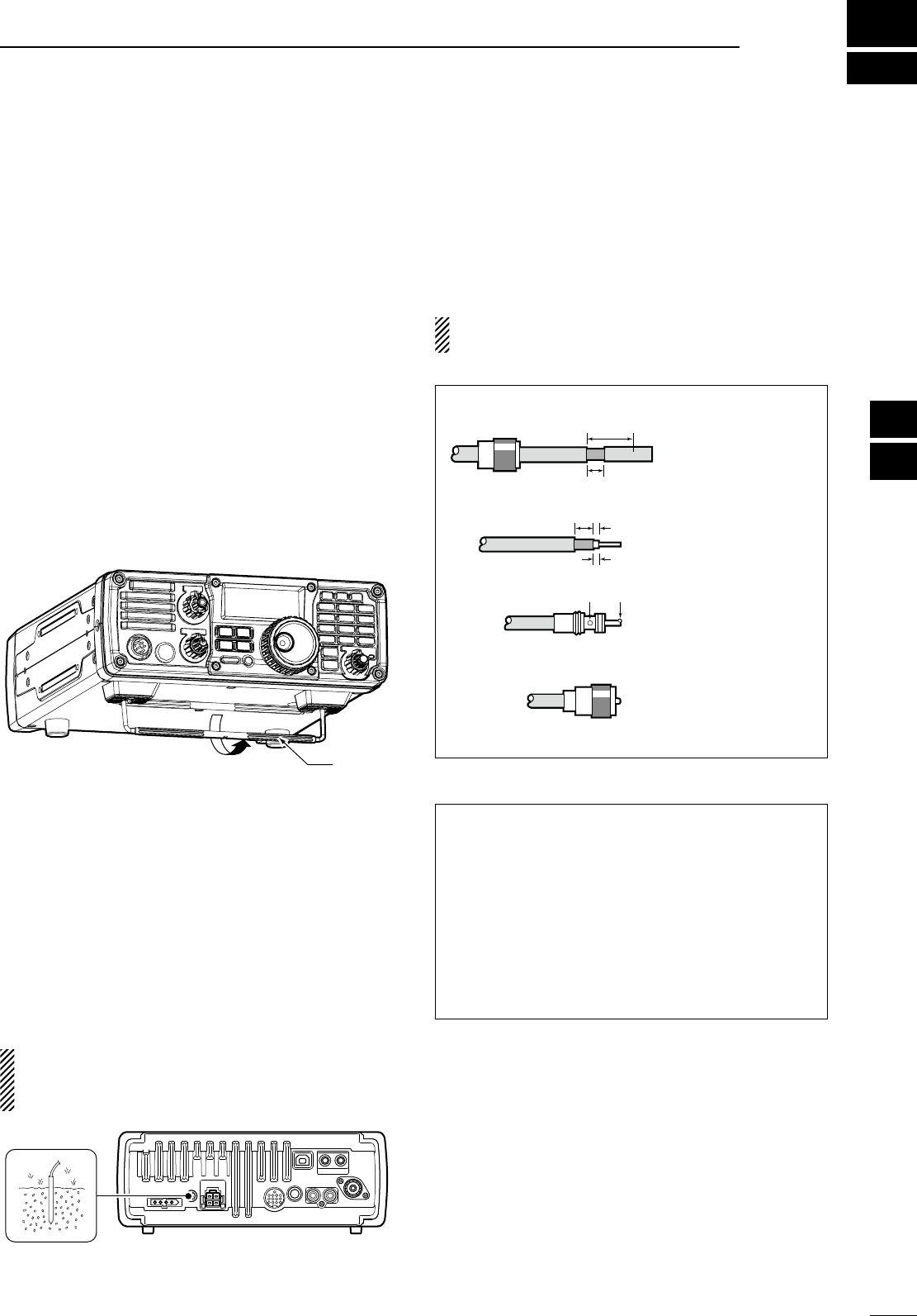
N
Selecting a location
Select a location for the transceiver that allows ade-
quate air circulation, free from extreme heat, cold, or
vibrations, and away from TV sets, TV antenna ele-
ments, radios and other electromagnetic sources.
The base of the transceiver has an adjustable stand
for desktop use. Set the stand to one of two angles
depending on your operating conditions.
Stand
N
Grounding
To prevent electrical shock, television interference
(TVI), broadcast interference (BCI) and other prob-
lems, ground the transceiver through the GROUND
terminal on the rear panel.
For best results, connect a copper or copper-plated
ground rod driven into the earth. Make the distance
between the [GND] terminal and ground as short and
straight as possible.
R WARNING: NEVER connect the [GND]
terminal to a gas or electric conduit, since the con-
nection could cause an explosion or electric shock.
[GND]
N
Antenna connection
For radio communications the antenna is of criti-
cal importance for output power and sensitivity. Use
well-matched 50 ø antennas and coaxial feedline. An
SWR (standing wave ratio) of 1.5:1 or lower is recom-
mended when transmitting.
CAUTION: Protect your transceiver from light-
ning by using a lightning arrestor.
Antenna SWR
Each antenna is tuned for a specified frequency
range and SWR may be increased out-of-range.
When the SWR is higher than approx. 2.0:1, the
transceiver’s power drops to protect the final transis-
tor. In this case, an optional antenna tuner is useful
to match the transceiver and antenna. Low SWR al-
lows full power for transmitting even when using the
antenna tuner. The IC-7200 has an SWR meter to
monitor the antenna SWR continuously
.
PL-259 CONNECTOR INSTALLATION EXAMPLE
30 mm
10 mm (soft solder)
10 mm
1–2 mm
solder solder
Soft
solder
Coupling ring
Slide the coupling ring
down. Strip the cable
jacket and soft solder.
Slide the connector
body on and solder it.
Screw the coupling
ring onto the connec-
tor body.
Strip the cable as
shown at left. Soft sol-
der the center con-
ductor.
q
w
e
r
30 mm (9⁄8 in) 10 mm (3⁄8 in) 1–2 mm (1⁄16 in)
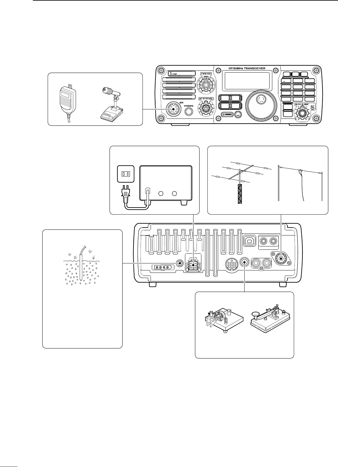
N
Required connections
• Front panel
i7200
MODE
TUNER
TS
FILTER
SPCH
V/M
A/B
SPLIT
M-CL
SCAN
SET
ATT
P
.
AMP
COMP
VOX
MNF
RIT
123
456
78
0
50
28
1814
10
21 24
=
7
3.5
1.8
F-INP
M-CH/RIT
ENT
BAND
GENE
9
.
AGC
MW
ANF
METER
NRNB
MICROPHONES (p. 11)
SM-20HM-36
• Rear panel
GROUND (p. 12)
Use the heaviest gauge wire
or strap available and make
the connection as short and
straight as possible.
Grounding prevents electrical
shocks, TVI and other prob-
lems.
CW KEY
A straight key can be used when the
internal electronic keyer is turned
OFF in initial set mode. (p. 80)
HF/50 MHz ANTENNADC POWER SUPPLY (p.15)
A DC power supplyAC outlet
13.8 V; at least 22 A
Black
_
Red
+
13
2INSTALLATION AND CONNECTIONS
14
2
INSTALLATION AND CONNECTIONS
1
2
3
4
5
6
7
8
9
10
11
12
13
14
15
16
17
18
19
20
21
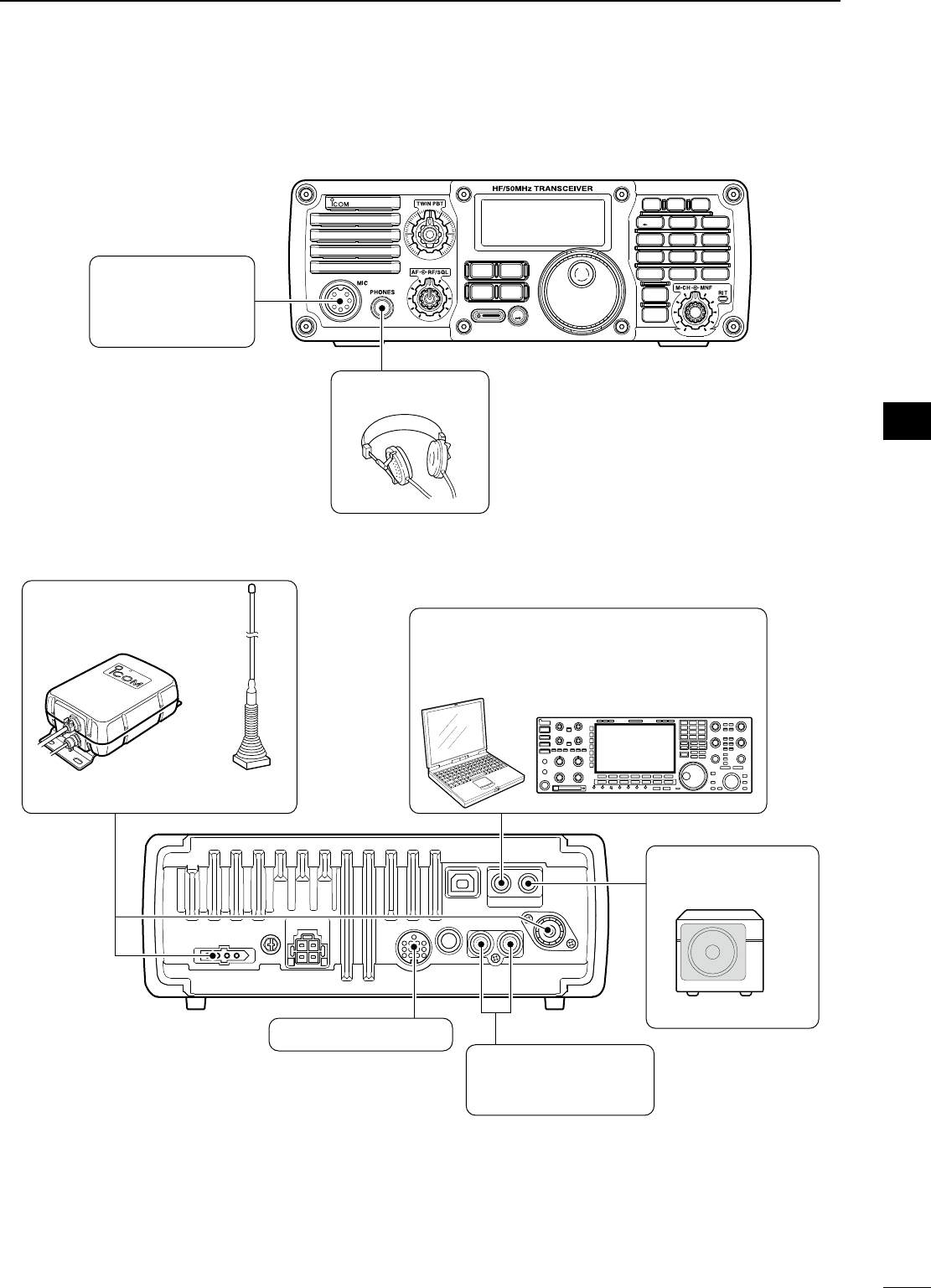
N
Advanced connections
• Front panel
i7200
MODE
TUNER
TS
FILTER
SPCH
V/M
A/B
SPLIT
M-CL
SCAN
SET
ATT
P
.
AMP
COMP
VOX
MNF
RIT
123
456
78
0
50
28
1814
10
21 24
=
7
3.51.8
F-INP
M-CH/RIT
ENT
BAND
GENE
9
.
AGC
MW
ANF
METER
NRNB
HEADPHONES
MIC
The AFSK modulation
signal can be input
from [MIC]. (p. 19)
• Rear panel
ACC SOCKET (p. 10)
AH-4 (p. 16) AH-2b
or long wire
with
EXTERNAL
SPEAKER (p. 91)
SP-21
REMOTE (p. 87)
Used for computer control and transceive
operation.
[SEND], [ALC] (p. 17)
Used for connecting a
non-Icom linear amplifier.
15
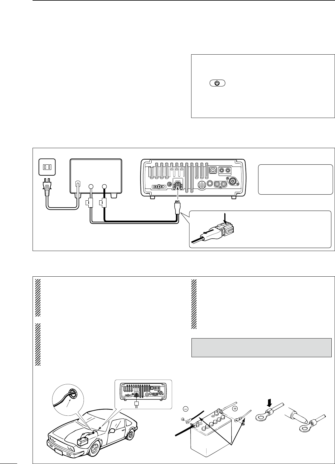
N
Power supply connections
N
Connecting the DC Power Supply
N
Battery connections
• RWARNING NEVER connect to a battery
without supplying a DC fuse, otherwise a fire
hazard occurs.
• NEVER connect the transceiver to a 24 V
battery.
The transceiver may not receive well on some
frequencies when installed in a hybrid vehicle, or
any type of electric vehicle (fuel cell vehicle). This
is because vehicle’s electric components such as
the inverter system generate a lot of electric
noise.
•
DO NOT use a cigarette lighter socket as a power
source when operating in a vehicle. The plug may
cause voltage drops and ignition noise may be
superimposed onto transmit or receive audio.
• Use a rubber grommet when passing the DC
power cable through a metal plate to prevent a
short circuit.
The IC-7200 is not certified for vehicle installation
in European countries.
Grommet
CONNECTING A VEHICLE BATTERY
Note: Use terminals for
the cable connections.
Crimp
Solder
Supplied
DC power cable
red
black
12 V
battery
2INSTALLATION AND CONNECTIONS
Use a DC power supply with a 22 A capacity when
operating the transceiver with AC power. Refer to the
diagrams below.
CAUTION: Before connecting the DC power
cable, check the following important items. Make
sure:
• The switch is OFF.
• Output voltage of the power source is 12–15 V.
• DC power cable polarity is correct.
Red : Positive + terminal
Black : Negative _ terminal
A DC power supplyAC outlet
AC cable
30 A fuses
Supplied DC power cable
13.8 V; at least 22 A
Black
_
Red
+
Transceiver
To DC power socket
BE CAREFUL when disconnecting
the DC power cable because the
connector is tightly locked. Use a small
tool, such as a flat-bladed screwdriver,
to disengage the locking tab.
R CAUTION! The rear panel
will become hot when operat-
ing the transceiver continu-
ously for long periods.
16
1
2
3
4
5
6
7
8
9
10
11
12
13
14
15
16
17
18
19
20
21
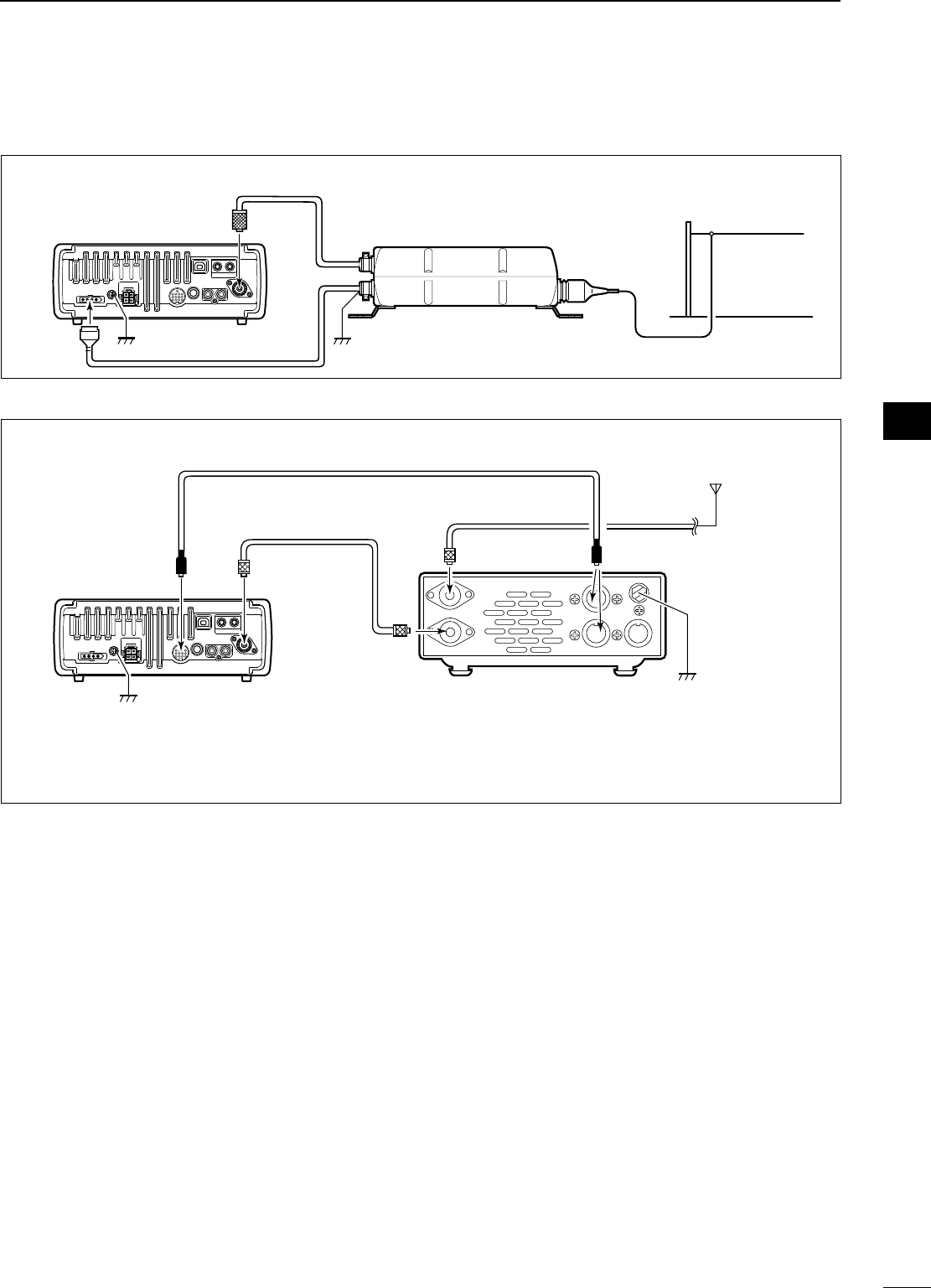
N
External antenna tuners
CONNECTING THE AH-4
Ground
Ground
Long wire or optional AH-2b
AH-4
[ANT]
IC-7200
Coaxial cable
(from the AH-4)
[TUNER]
CONNECTING THE AT-180
IC-7200
Ground
AT-180
HF
to 6 m
antenna
[TRANSCEIVER]
[ANT]
[ANT]
[ACC] [ACC]
ACC cable supplied with the AT-180
Coaxial cable supplied
with the AT-180
Either of the two
external connectors
Ground
• Turn the IC-7200’s power OFF when connecting
the AT-180, otherwise, the CPU may malfunction
and the AT-180 may not function properly.
2
INSTALLATION AND CONNECTIONS
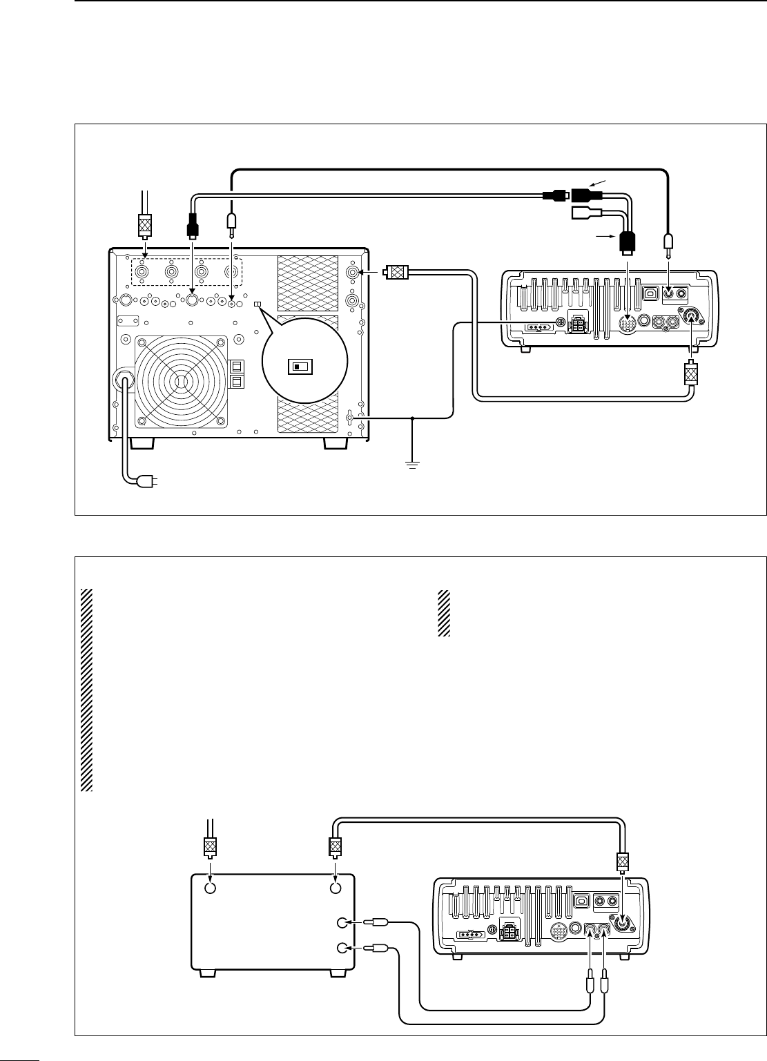
17
CONNECTING THE IC-PW1/EURO
To an
antenna [ACC-1]
[ANT]
[ACC]
[INPUT1]
[REMOTE]
EXCITER
11&2
[GND]
[GND]
IC-PW1/EURO
To AC outlet
Non-European versions : 100–120/220–240 V
European version : 230 V
Ground
Transceiver
[REMOTE]
Remote control cable
(supplied with the IC-PW1/EURO)
ACC cable
(supplied with the IC-PW1/EURO)
Coaxial cable
(supplied with the IC-PW1/EURO)
7-pin side
OPC-599 conversion cable
()
[ANT]
N
Linear amplifier connections
CONNECTING A NON-ICOM LINEAR AMPLIFIER
R WARNING:
• Set the transceiver output power and linear am-
plifier ALC output level by referring to the linear
amplifier instruction manual. Be sure the linear
amplifier keying circuit control voltage is compat-
ible with the IC-7200, before connecting to the
[SEND] connector.
• The ALC input level must be in the range +0 V to
–4 V, and the transceiver does not accept posi-
tive voltage. Non-matched ALC and RF power
settings could cause a fire or damage the linear
amplifier.
The IC-7200 SEND line is rated at 16 V/200 mA
DC. If this level is exceeded, a larger external
relay must be used.
Transceiver
50 ø coaxial cable
RF OUTPUT RF INPUT
ALC
SEND
[ANT]
[ALC]
[SEND]
To an
antenna
Non-Icom linear amplifier
2INSTALLATION AND CONNECTIONS
18
1
2
3
4
5
6
7
8
9
10
11
12
13
14
15
16
17
18
19
20
21
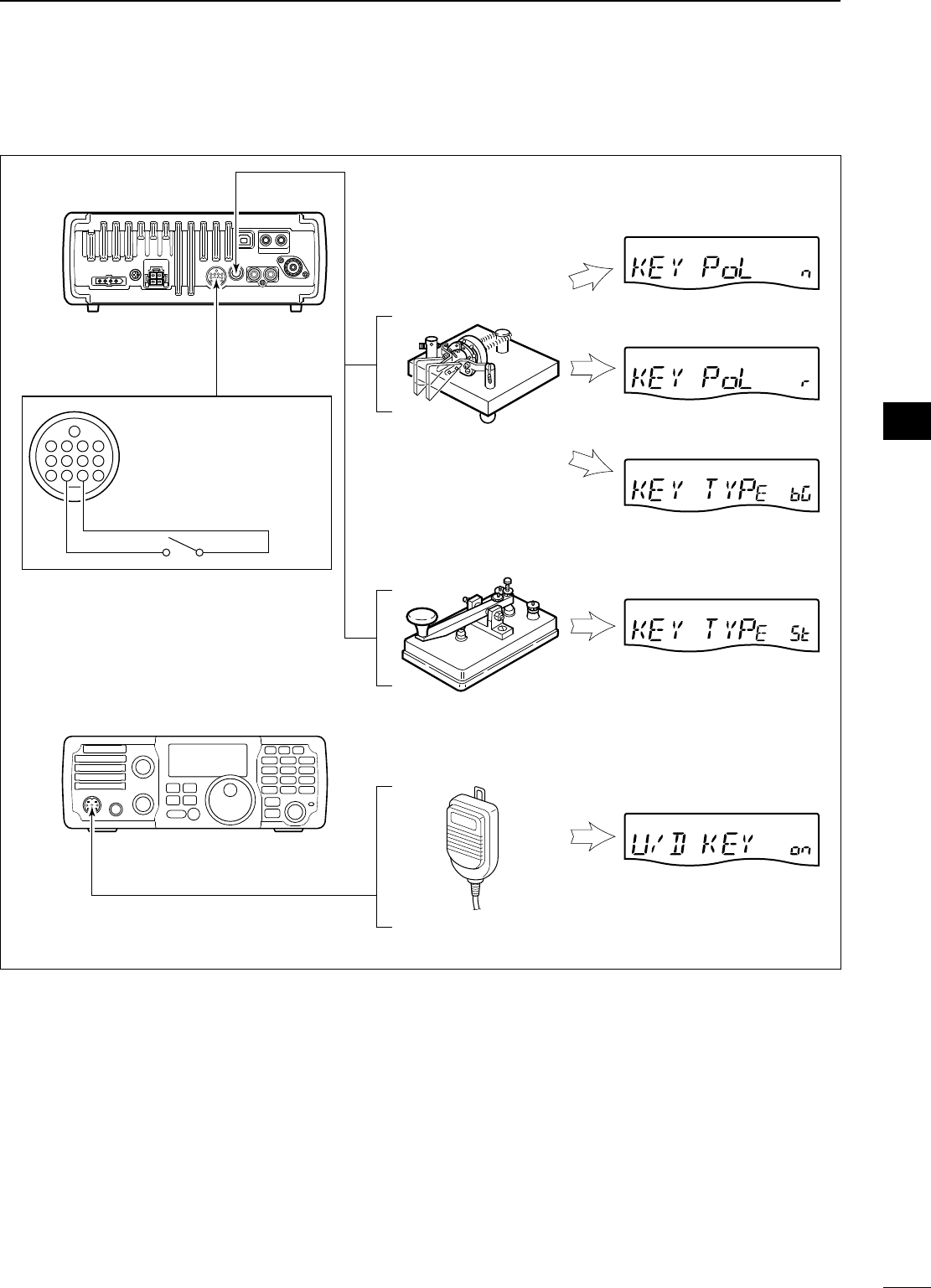
NConnections for CW
Rear panel
Paddle
KEY
MIC
Straight key
Microphone (HM-36)
Set mode settings (p. 80)
4
8
12
ACC
123
765
9
10 11
13
For no break-in operation:
Connect an external switch
such as a foot switch; or use
the RTTY SEND terminal for
all bands. (See p. 19)
See p. 82 for connection details:
Paddle operation from the [MIC]
connector.
Bug
Reverse
Normal
Mic Up/Down keyer: ON
Keyer type: Straight-key
Keyer type: Bug-key
Paddle polarity: Reverse
Paddle polarity: Normal
2
INSTALLATION AND CONNECTIONS
19
2INSTALLATION AND CONNECTIONS
NConnections for RTTY
D Connections for RTTY (FSK)
[ACC]
Rear panel
4
8
12
123
765
9
10 11
13
(Rear panel view)
PC
*Connect SQL line when required.
SQL* (light green)
FSKK (black)
AF out (light blue)
HSEND (orange)
GND (red)
TNC or PC interface
for the RTTY software
Colors refer to the wires in
the supplied ACC cable.
D Connections for RTTY (AFSK)
[MIC]
Front panel
i AF out
PC
*Connect SQL line when required.
TNC or PC interface
for the RTTY software
r SQL* t PTT
y GND u GND
q MIC
(Front panel view)
20
2
INSTALLATION AND CONNECTIONS
1
2
3
4
5
6
7
8
9
10
11
12
13
14
15
16
17
18
19
20
21
NConnections for SSTV or PSK31
D When connecting to the [ACC] socket
[ACC]
Rear panel
4
8
12
123
765
9
10 11
13
*Connect SQL line when required.
SQL* (light green)
AF in (pink)
AF out (light blue)
HSEND (orange)
GND (red)
PC
TNC or
PC interface for the software
Colors refer to the wires in
the supplied ACC cable.
(Rear panel view)
D When connecting to the [MIC] connector
[MIC]
Front panel
i AF out
PC
*Connect SQL line when required.
TNC or PC interface
for the software
r SQL* t PTT
y GND u GND
q MIC
(Front panel view)
N When first applying power (CPU resetting)
N Initial settings
After resetting the transceiver, set controls and
switches as shown in the figure below.
i7200
MODE
TUNER
TS
FILTER
SPCH
V/M
A/B
SPLIT
M-CL
SCAN
SET
ATT
P
.
AMP
COMP
VOX
MNF
RIT
123
456
78
0
50
28
1814
10
21 24
=
7
3.51.8
F-INP
M-CH/RIT
ENT
BAND
GENE
9
.
AGC
MW
ANF
METER
NRNB
[TWIN PBT]: Center
* CCW: counterclockwise [POWER]: OFF
[RF/SQL]: Center
[AF]: Max. CCW*
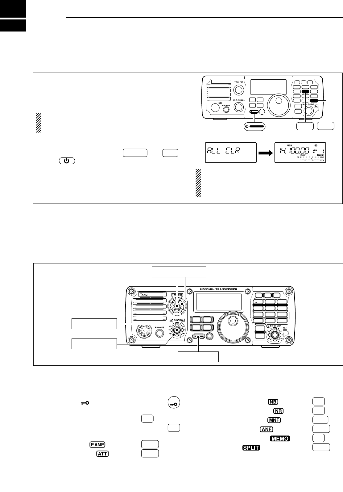
Before first applying power, make sure all connec-
tions required for your system are complete by refer-
ring to Chapter 2. Then, reset the transceiver using
the following procedure.
Resetting CLEARS all programmed contents in
memory channels and returns the quick set
mode/set mode to default values.
q Make sure the transceiver power is OFF.
w While pushing and holding F-INP ENT
BAND and M-CL ,
push to turn power ON.
• The internal CPU is reset.
• The transceiver displays its initial VFO frequencies
when resetting is complete.
e All quick set mode/set mode settings are returned
to default values. (p. 70)
MODE
TUNER
TS
FILTER
SPCH
V/M
A/B
SPLIT
M-CL
SCAN
SET
ATT
P
.
AMP
COMP
VOX
MNF
RIT
123
456
78
0
50
28
1814
10
21 24
=
7
3.5
1.8
F-INP
M-CH/RIT
ENT
BAND
GENE
9
.
AGC
MW
ANF
METER
NR
NB
M-CL
5
14
F-INP ENT
BAND
Under cooler temperatures, the LCD may appear
dark and unstable after turning power ON. This is
normal and does not indicate any equipment mal-
function.
3
21
BASIC OPERATION
Turn power ON, then check the display. If any of the
following indicators appear, turn them OFF as follows:
• Lock indicator, “ ” : Push and hold
SPCH
for 1 sec.
• Tuning step indicator, “√” : Push
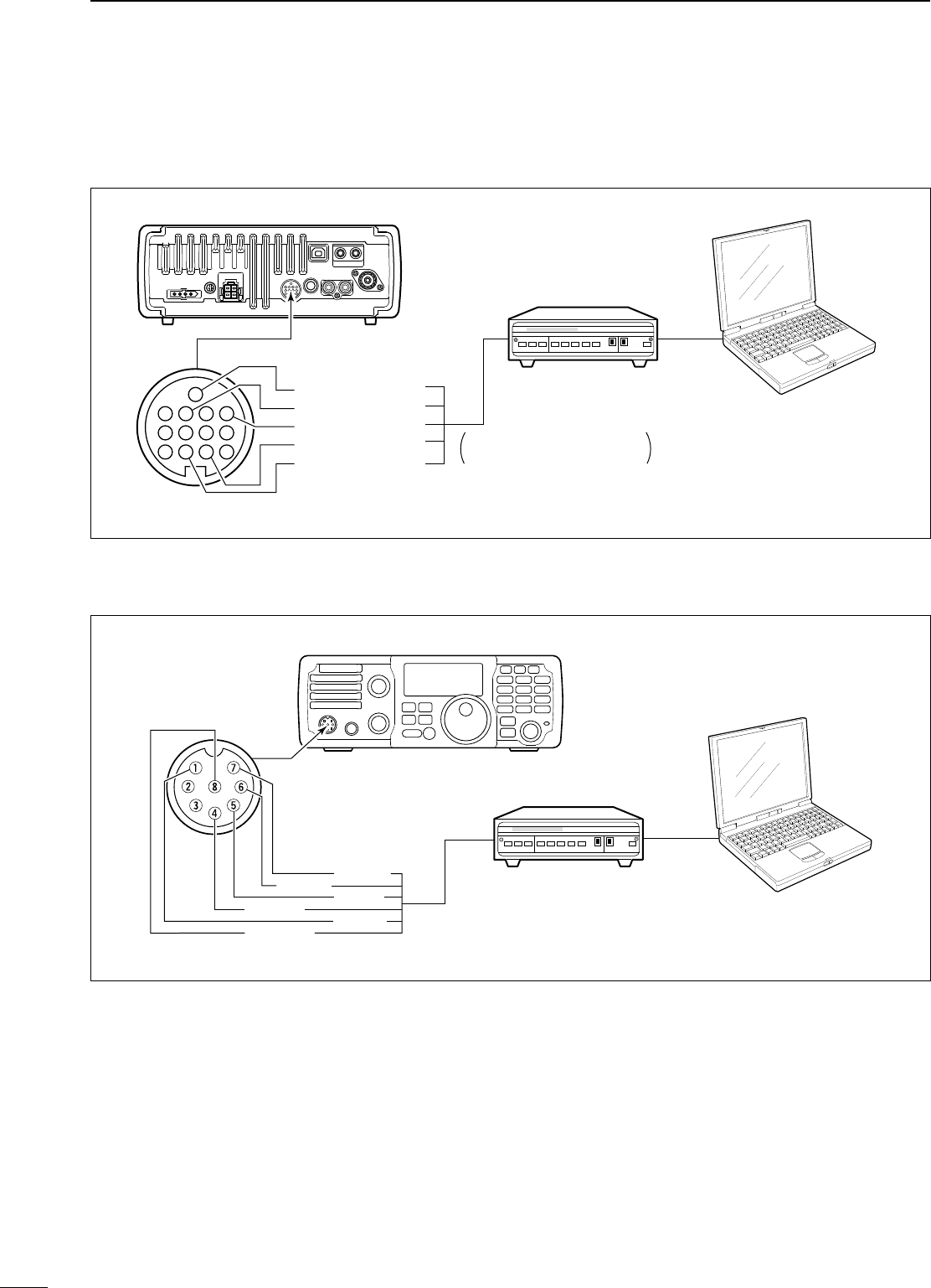
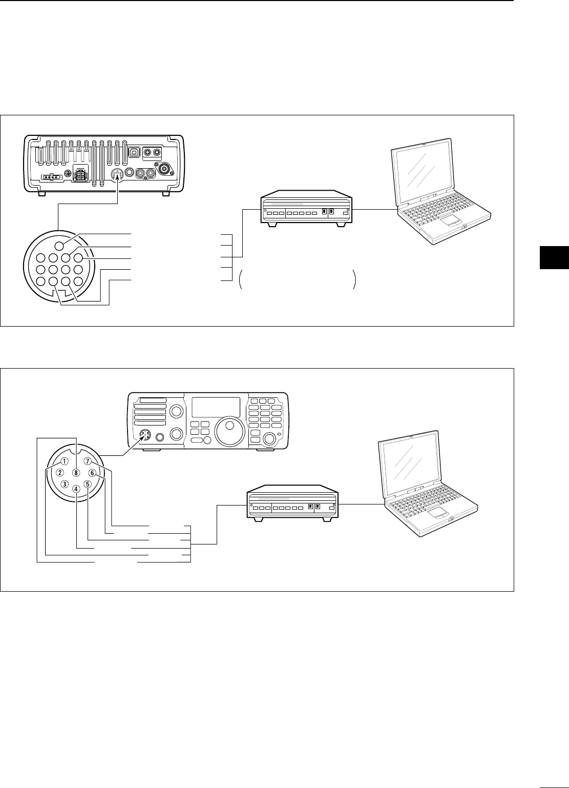
TS .
• 1 Hz frequency readout : Push and hold TS
for 1 sec.
• Preamp indicator, “ ” : Push
P.AMP
ATT .
• Attenuator indicator, “ ” : Push
P.AMP
ATT .
• Noise blanker indicator, “ ” : Push
NB .
• Noise reduction indicator, “ ” : Push
NR .
• Manual notch indicator, “ ” : Push
MNF .
• Auto notch indicator, “ ” : Push
ANF
METER .
• Memory mode indicator, “ ” : Push V/M
• Split indicator, “ ” : Push
SPLIT .
22
3
BASIC OPERATION
1
2
3
4
5
6
7
8
9
10
11
12
13
14
15
16
17
18
19
20
21
N VFO description
VFO is an abbreviation of Variable Frequency Oscilla-
tor, and traditionally refers to an oscillator.
The IC-7200 VFO can store a frequency and an oper-
ating mode.
You can call up a desired frequency to the VFO with
the keypad or the memory copy function (see p. 63).
You can also change the frequency with [DIAL] and
select an operating mode with
MODE
or call up previ-
ously accessed frequency and modes with the band
stacking register (p. 24).
The IC-7200 has two VFOs, specially suited for split
frequency operation. The VFOs are called VFO A and
VFO B. You can use the desired VFO to call up a fre-
quency and operating mode for operation.
Select
MEMORY
CHANNEL
DIAL
7.001 MHz
21.295 MHz
BAND
Change
Transfer
Transfer
VFO
N VFO operation
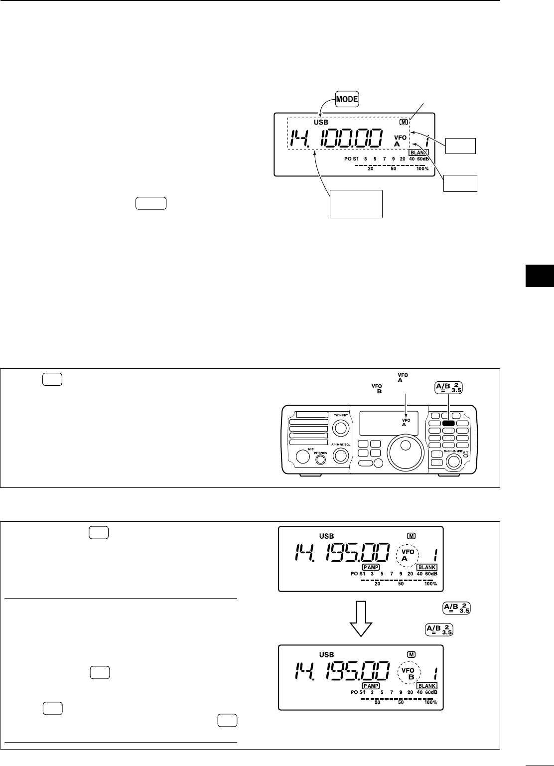
D Selecting the VFO A/B
D VFO equalization
± Push A/B
=
to toggle VFO A or VFO B.
MODE
TUNER
TS
FILTER
SPCH
V/M
A/B
SPLIT
M-CL
SCAN
SET
ATT
P
.
AMP
COMP
VOX
MNF
RIT
123
456
78
0
50
28
1814
10
21 24
=
7
3.5
1.8
F-INP
M-CH/RIT
ENT
BAND
GENE
9
.
AGC
MW
ANF
METER
NR
NB
Either “ ” or
“ ” appears.
± Push and hold A/B
=
for 1 sec. to set the undis-
played VFO frequency and mode to the displayed
VFO frequency
• 3 beeps sound when the VFO equalization is
completed.
CONVENIENT
Use two VFOs as a quick memory
When you find a new station, but you wish to con-
tinue searching, the two VFO system can be used for
quick memory storage.
q Push and hold A/B
=
for 1 sec. to store the dis-
played frequency into the undisplayed VFO.
w Continue searching for stations.
e Push A/B
=
to retrieve the stored frequency.
r To continue searching for a station, push A/B
=
again.
Push and hold
for 1 sec.,
then push again.
23
3BASIC OPERATION
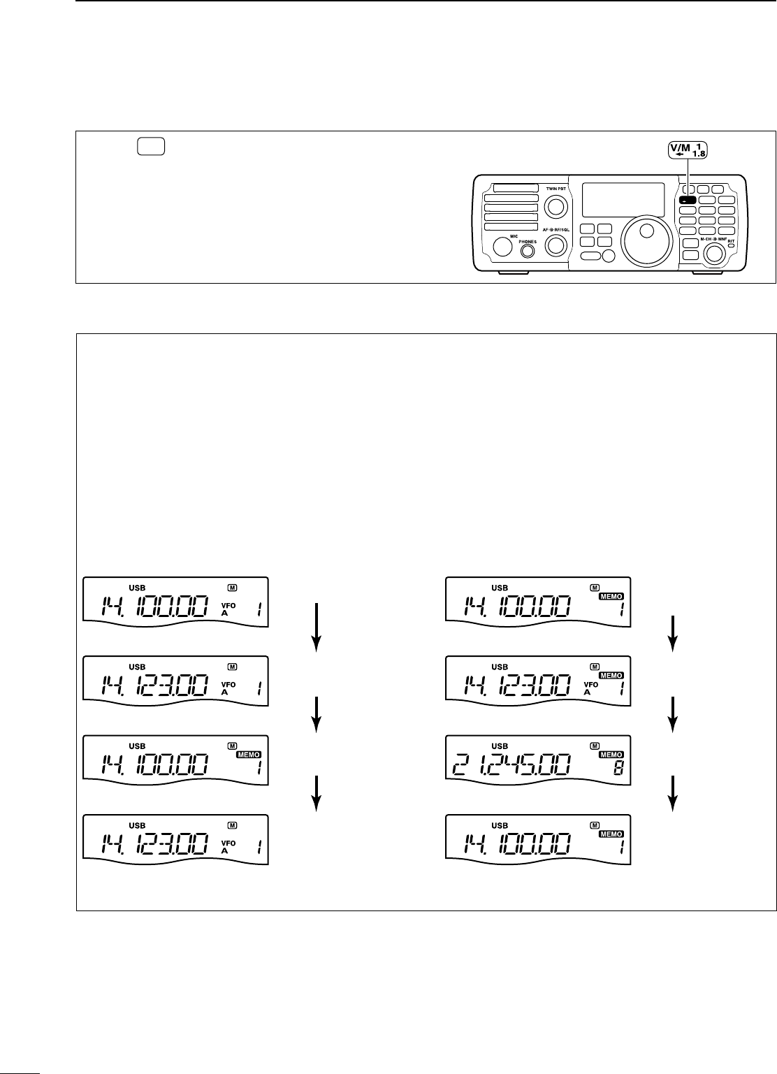
N Selecting VFO/memory mode
± Push V/M
to toggle between VFO and memory
modes.
MODE
TUNER
TS
FILTER
SPCH
V/M
A/B
SPLIT
M-CL
SCAN
SET
ATT
P
.
AMP
COMP
VOX
MNF
RIT
123
456
78
0
50
28
1814
10
21 24
=
7
3.5
1.8
F-INP
M-CH/RIT
ENT
BAND
GENE
9
.
AGC
MW
ANF
METER
NR
NB
D Differences between VFO mode and memory mode
VFO MODE
Each VFO shows a frequency and operating mode.
If the frequency or operating mode is changed, the
VFO automatically memorizes the new frequency or
operating mode.
When the VFO is selected from another VFO or
memory mode, the last used frequency and operat-
ing mode for that VFO appears.
[EXAMPLE]
Changed frequency (14.123 MHz) does not appear and
memorized frequency (14.100 MHz) appears instead.
Memory channel 1
is selected.
The frequency is
changed.
Memory channel 1
is selected again.
Another memory
channel is selected.
VFO is selected.
The frequency is
changed.
VFO is selected
again.
Changed frequency (14.123 MHz) appears.
Memory mode is
selected.
MEMORY MODE (pgs. 61–64)
Each memory channel shows a frequency and op-
erating mode like a VFO. Even if the frequency or
mode is changed, the memory channel does not
memorize the new frequency or operating mode.
When the memory channel is selected from another
memory channel or VFO mode, the memorized
frequency and operating mode appear even if the
memory channel settings, frequency and mode, are
changed before selecting another memory channel
or VFO mode.
[EXAMPLE]
24
3
BASIC OPERATION
1
2
3
4
5
6
7
8
9
10
11
12
13
14
15
16
17
18
19
20
21
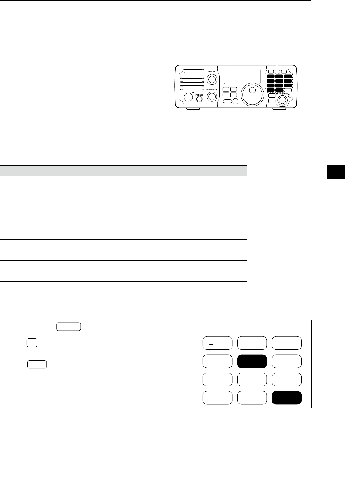
N Selecting an operating band
The transceiver has a band stacking register. This
function automatically memorizes the last operating
frequency and mode used on a particular band.
This is convenient for contest operation.
See the table below for a list of the bands availa-
ble and the default settings for each register. And to
send or read the desired band stacking register’s con-
tents, a combination of the frequency band and reg-
ister codes as follows are used with the CI-V system.
(p. 88)
For example, when sending/reading the oldest con-
tents in the 21 MHz band, the code “07” is used.
BAND REGISTER CODE FREQUENCY RANGE
1.8 MHz 1.900000 MHz CW 01 1.800000 – 1.999999
3.5 MHz 3.550000 MHz LSB 02 3.400000 – 4.099999
7 MHz 7.050000 MHz LSB 03 6.900000 – 7.499999
10 MHz 10.120000 MHz CW 04 9.900000 – 10.499999
14 MHz 14.100000 MHz USB 05 13.900000 – 14.499999
18 MHz 18.100000 MHz USB 06 17.900000 – 18.499999
21 MHz 21.200000 MHz USB 07 20.900000 – 21.499999
24 MHz 24.950000 MHz USB 08 24.400000 – 25.099999
28 MHz 28.500000 MHz USB 09 28.000000 – 29.999999
50 MHz 50.100000 MHz USB 10 50.000000 – 54.000000
General 15.000000 MHz USB 11 Other than above
D Using the band stacking register
q Push and hold F-INP ENT
BAND for 1 sec. to enter the
band selection mode.
w Push 5
14 to select 14 MHz band.
• The last operated frequency and mode are memo-
rized.
e Push MODE to select an operating mode; rotate
[DIAL] to select an operating frequency.
V/M
A/B
SPLIT
M-CL
SCANCOMP
VOX
MNF
RIT
123
456
78
0
50
28
1814
10
21 24
=
7
3.5
1.8
F-INP ENT
BAND
GENE
9
.
AGC
MW
[Example]: 14 MHz band
MODE
TUNER
TS
FILTER
SPCH
V/M
A/B
SPLIT
M-CL
SCAN
SET
ATT
P
.
AMP
COMP
VOX
MNF
RIT
123
456
78
0
50
28
1814
10
21 24
=
7
3.5
1.8
F-INP
M-CH/RIT
ENT
BAND
GENE
9
.
AGC
MW
ANF
METER
NR
NB
Band keys
25
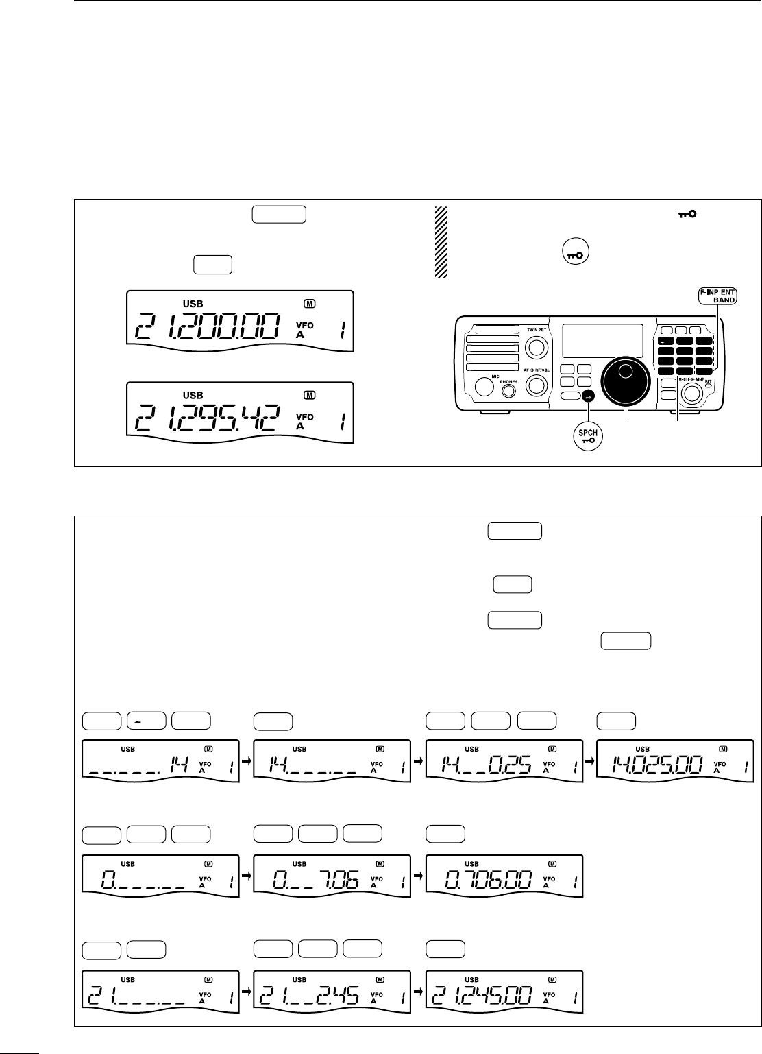
N Frequency setting
The transceiver has several tuning methods for con-
venient frequency tuning.
D Using the main dial
q
After pushing and holding
F-INP ENT
BAND
for 1 sec., push
the desired band key to select the corresponding
band.
• When you push •
GENE , the general coverage receiver
band is selected.
w Rotate [DIAL] to set the desired frequency.
If the dial lock function is activated, “ ” (lock in-
dicator) appears, and [DIAL] does not function.
± Push and hold
SPCH
for 1 sec. to deactivate the
lock function. (see p. 29 for details)
MODE
TUNER
TS
FILTER
SPCH
V/M
A/B
SPLIT
M-CL
SCAN
SET
ATT
P
.
AMP
COMP
VOX
MNF
RIT
123
456
78
0
50
28
1814
10
21 24
=
7
3.5
1.8
F-INP
M-CH/RIT
ENT
BAND
GENE
9
.
AGC
MW
ANF
METER
NR
NB
Band keys
[DIAL]
D Direct frequency entry with keypad
The transceiver has a keypad for direct frequency
entry as described at right.
q Push F-INP ENT
BAND .
w Input the desired frequency with the numeral keys
on the keypad.
• Push •
GENE to input “• (decimal point)” between the
MHz digits and kHz digits.
e Push F-INP ENT
BAND to set the input frequency.
• To cancel the input, push M-CH/RIT
SET (or any key except
keypad).
• 21.280 MHz 21.245 MHz
• 14.025 MHz
[EXAMPLE]
• 706 kHz
F-INP ENT
BAND
F-INP ENT
BAND
RIT
GENE
.
F-INP ENT
BAND
F-INP ENT
BAND
4
10
MW
V/M
1
1.8
RIT
GENE
.
MNF
0
50
M-CL
5
14
A/B
2
=
3.5
F-INP ENT
BAND
MNF
0
50
RIT
GENE
.
MNF
0
50
COMP
7
21
6
18
AGC
M-CL
5
14
A/B
2
=
3.5
4
10
MW
F-INP ENT
BAND
3BASIC OPERATION
26
1
2
3
4
5
6
7
8
9
10
11
12
13
14
15
16
17
18
19
20
21
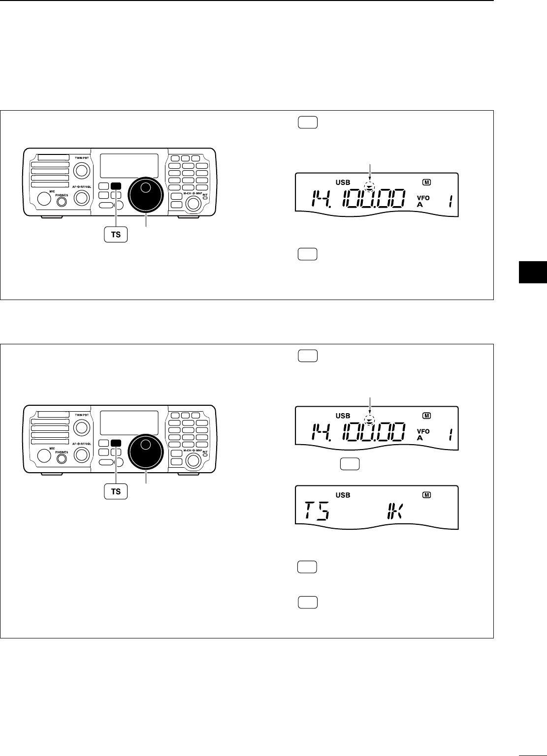
D Programmable tuning steps
D Selecting the programmable tuning step
Programmable tuning steps are available to suit your
operating requirements.
These tuning steps are:
• Selectable from 0.1, 1, 5, 9 and 10 kHz
MODE
TUNER
TS
FILTER
SPCH
V/M
A/B
SPLIT
M-CL
SCAN
SET
ATT
P
.
AMP
COMP
VOX
MNF
RIT
123
456
78
0
50
28
1814
10
21 24
=
7
3.5
1.8
F-INP
M-CH/RIT
ENT
BAND
GENE
9
.
AGC
MW
ANF
METER
NR
NB
[DIAL]
q Push TS to turn the programmable tuning func-
tion ON.
• “Z” appears.
Programmable tuning step indicator
w Push and hold TS for 1 sec. to enter the tuning
step set mode.
e Rotate [DIAL] to select the desired tuning step
from 0.1, 1, 5, 9 or 10 kHz.
r Push TS to exit the tuning step set mode.
t Rotate [DIAL] to change the frequency according
to the set tuning step.
y Push TS to turn the programmable tuning func-
tion OFF.
• “Z” disappears.
The operating frequency can be changed in steps of
(0.1, 1, 5, 9 or 10 kHz selectable) for quick tuning.
MODE
TUNER
TS
FILTER
SPCH
V/M
A/B
SPLIT
M-CL
SCAN
SET
ATT
P
.
AMP
COMP
VOX
MNF
RIT
123
456
78
0
50
28
1814
10
21 24
=
7
3.5
1.8
F-INP
M-CH/RIT
ENT
BAND
GENE
9
.
AGC
MW
ANF
METER
NR
NB
[DIAL]
q Push TS to turn the programmable tuning func-
tion ON.
• “Z” appears.
Programmable tuning step indicator
w Rotate [DIAL] to change the frequency in pro-
grammed kHz steps.
e Push TS again to turn the programmable tuning
function OFF.
• “Z” disappears.
r Rotate [DIAL] for normal tuning, if desired.
3
BASIC OPERATION
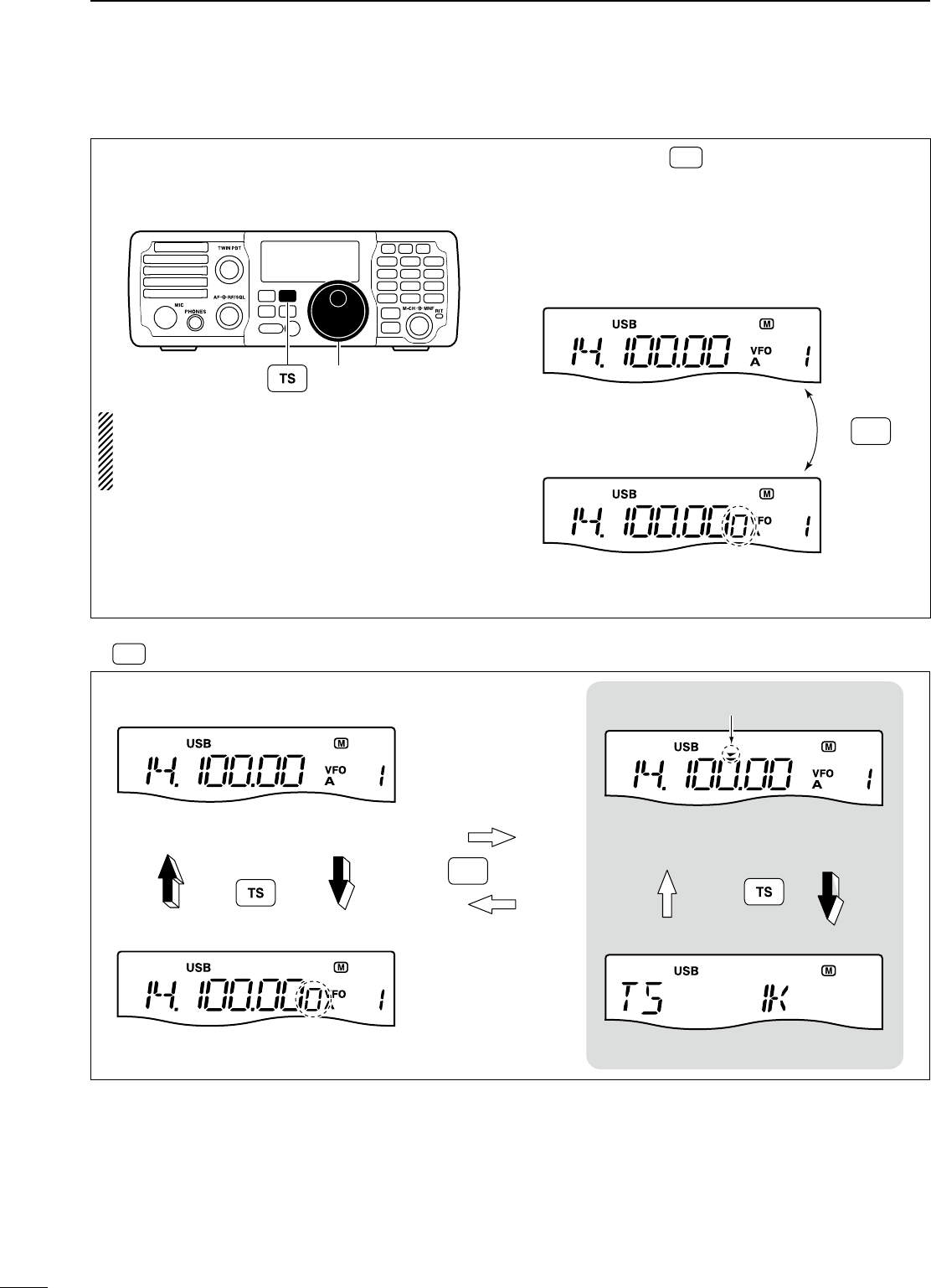
27
D 1 Hz and 10 Hz tuning steps
When the programmable tuning step “Z” disappears,
rotating [DIAL] changes the frequency in increments
of 1 or 10 Hz.
MODE
TUNER
TS
FILTER
SPCH
V/M
A/B
SPLIT
M-CL
SCAN
SET
ATT
P
.
AMP
COMP
VOX
MNF
RIT
123
456
78
0
50
28
1814
10
21 24
=
7
3.5
1.8
F-INP
M-CH/RIT
ENT
BAND
GENE
9
.
AGC
MW
ANF
METER
NR
NB
[DIAL]
NOTE: The frequency is changed in 50 Hz step
when the [UP]/[DN] switches of the microphone
are used for the frequency setting even if the 1 Hz
tuning is selected.
± Push and hold TS for 1 sec. to toggle between
the 1 Hz and 10 Hz step settings.
•
When the 1 Hz step is selected, the 1 Hz digit appears in
the frequency indication; when the 10 Hz step is selected,
the 1 Hz digit disappears from the frequency indication.
• Rotating [DIAL] changes the frequency in 1 Hz or
10Hz tuning step.
Push and hold
for 1 sec.
Rotating [DIAL] changes the
frequency in 10 Hz steps.
Rotating [DIAL] changes the
frequency in 1 Hz steps.
TS
Appears
10 Hz tuning
1 Hz tuning
D TS switch flow chart
1 Hz tuning
10 Hz tuning Programmable step tuning
(0.1 kHz –10 kHz)
Tuning step set mode
momentarily
1 sec.
1 sec.
1 sec.
Push and hold
Push
momentarilyPush
TS
Appears
Programmable tuning step indicator
3BASIC OPERATION
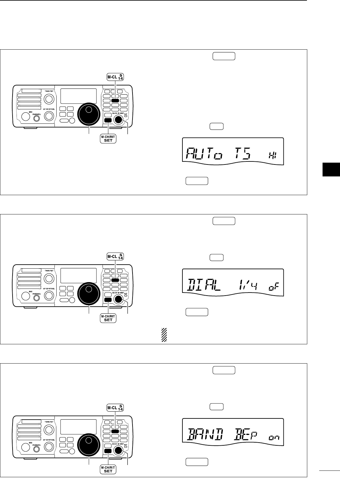
28
1
2
3
4
5
6
7
8
9
10
11
12
13
14
15
16
17
18
19
20
21
D Auto tuning step function
When rotating the tuning dial rapidly, the tuning
speed accelerates automatically as selected.
[DIAL]
MODE
TUNER
TS
FILTER
SPCH
V/M
A/B
SPLIT
M-CL
SCAN
SET
ATT
P
.
AMP
COMP
VOX
MNF
RIT
123
456
78
0
50
28
1814
10
21 24
=
7
3.5
1.8
F-INP
M-CH/RIT
ENT
BAND
GENE
9
.
AGC
MW
ANF
METER
NR
NB
[M-CH]
q Push and hold M-CH/RIT
SET for 1 sec. twice to enter
the set mode.
w Rotate [M-CH] to select “AUTo TS.”
e Rotate [DIAL] to select the desired tuning speed
from HI (High), Lo (Low) and oF (OFF).
• HI :
Approx. 5 times faster when the tuning step is set
to 1 kHz or smaller steps; approx. 2 times faster
when the tuning step is set to 5 kHz or larger steps.
• Lo : Approx. 2 times faster
• oF : Auto tuning step is turned OFF
• Push and hold M-CL for 1 sec. to select a default con-
dition or value.
When “HI” is selected (default)
r Push M-CH/RIT
SET to exit the set mode and return to
normal operation.
D ¼ tuning function (SSB data/AM data/CW/RTTY only)
While operating in SSB data/AM data/CW/RTTY, the
¼ tuning function is available for critical tuning. Dial
sensitivity is reduced to ¼ of normal when the ¼
function is in use.
[DIAL]
MODE
TUNER
TS
FILTER
SPCH
V/M
A/B
SPLIT
M-CL
SCAN
SET
ATT
P
.
AMP
COMP
VOX
MNF
RIT
123
456
78
0
50
28
1814
10
21 24
=
7
3.5
1.8
F-INP
M-CH/RIT
ENT
BAND
GENE
9
.
AGC
MW
ANF
METER
NR
NB
[M-CH]
q Push and hold M-CH/RIT
SET for 1 sec. twice to enter
the set mode.
w Rotate [M-CH] to select “DIAL ¼.”
e Rotate [DIAL] to select the ¼ tuning function ON
and OFF.
• Push and hold M-CL for 1 sec. to select a default con-
dition or value.
When “OFF” is selected (default)
r Push M-CH/RIT
SET to exit the set mode and return to
normal operation.
NOTE: This function is only available when the
programmable tuning step is OFF (p. 26).
D Band edge warning beep
When selecting a frequency that lies outside of a
band’s specified frequency range, a warning beep
sounds.
This function can be turned OFF in set mode, if de-
sired.
[DIAL]
MODE
TUNER
TS
FILTER
SPCH
V/M
A/B
SPLIT
M-CL
SCAN
SET
ATT
P
.
AMP
COMP
VOX
MNF
RIT
123
456
78
0
50
28
1814
10
21 24
=
7
3.5
1.8
F-INP
M-CH/RIT
ENT
BAND
GENE
9
.
AGC
MW
ANF
METER
NR
NB
[M-CH]
q Push and hold M-CH/RIT
SET for 1 sec. twice to enter
the set mode.
w Rotate [M-CH] to select “BAND BEP.”
e Rotate [DIAL] to select the band edge warning
beep function ON and OFF.
• Push and hold M-CL for 1 sec. to select a default con-
dition or value.
When “ON” is selected (default)
r Push M-CH/RIT
SET to exit the set mode and return to
normal operation.
3
BASIC OPERATION
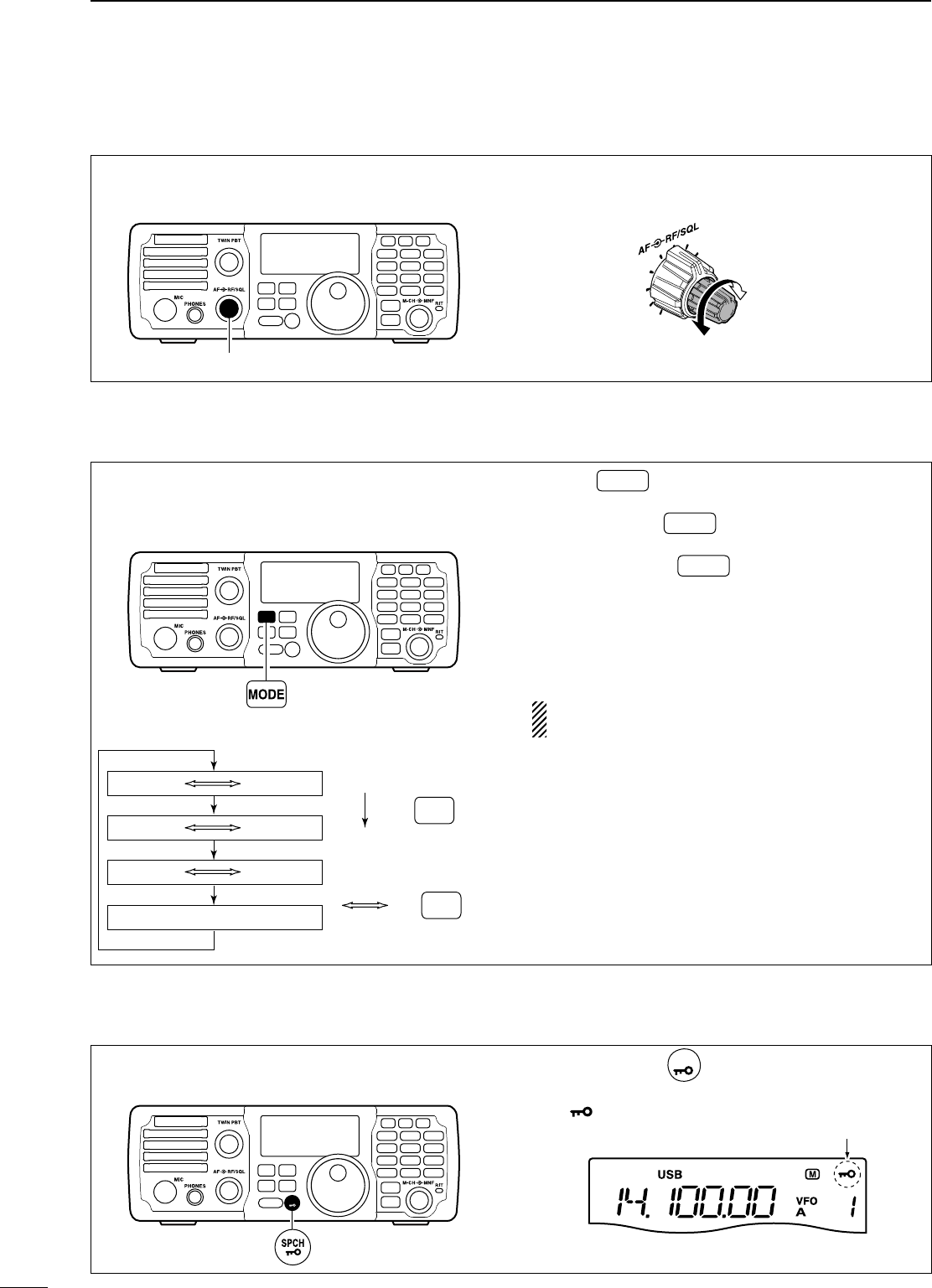
29
N Volume setting
Rotate the [AF] control clockwise to increase; coun-
terclockwise to decrease the audio output level.
• Set a suitable audio level.
MODE
TUNER
TS
FILTER
SPCH
V/M
A/B
SPLIT
M-CL
SCAN
SET
ATT
P
.
AMP
COMP
VOX
MNF
RIT
123
456
78
0
50
28
1814
10
21 24
=
7
3.5
1.8
F-INP
M-CH/RIT
ENT
BAND
GENE
9
.
AGC
MW
ANF
METER
NR
NB
[AF]
Audio output
decreases
Audio output
increases
N Operating mode selection
The following modes are available in the IC-7200:
SSB (USB/LSB), SSB data (USB data/LSB data),
CW,
CW-R (CW Reverse), RTTY, RTTY-R (RTTY Re-
verse)
, AM and AM data modes
MODE
TUNER
TS
FILTER
SPCH
V/M
A/B
SPLIT
M-CL
SCAN
SET
ATT
P
.
AMP
COMP
VOX
MNF
RIT
123
456
78
0
50
28
1814
10
21 24
=
7
3.5
1.8
F-INP
M-CH/RIT
ENT
BAND
GENE
9
.
AGC
MW
ANF
METER
NR
NB
OPERATING MODE SELECTION
Push and hold
for 1 sec.
MODE
USB LSB
AM
CW CW-R
RTTY-R
RTTY
Push
momentarily
MODE
± Push MODE one or more times to select desired
operation mode.
± Push and hold MODE for 1 sec. to toggle between
USB and LSB. (SSB mode only)
± Push and hold MODE for 1 sec. to toggle be-
tween CW and CW Reverse or RTTY and RTTY
Reverse. (CW and RTTY mode only)
± SSB data (USB data/LSB data) or AM data mode
can be selected in the set mode (p. 71)
• The selected mode is indicated in the function display.
NOTE: If a desired operating mode cannot be se-
lected, it may be disabled in the set mode (p. 81).
N Dial lock function
The dial lock function prevents accidental changes
caused by [DIAL].
MODE
TUNER
TS
FILTER
SPCH
V/M
A/B
SPLIT
M-CL
SCAN
SET
ATT
P
.
AMP
COMP
VOX
MNF
RIT
123
456
78
0
50
28
1814
10
21 24
=
7
3.5
1.8
F-INP
M-CH/RIT
ENT
BAND
GENE
9
.
AGC
MW
ANF
METER
NR
NB
±Push and hold
SPCH
for 1 sec. to turn the dial lock
function ON and OFF.
• “ ” appears while the dial lock function is activated.
Appears
3BASIC OPERATION
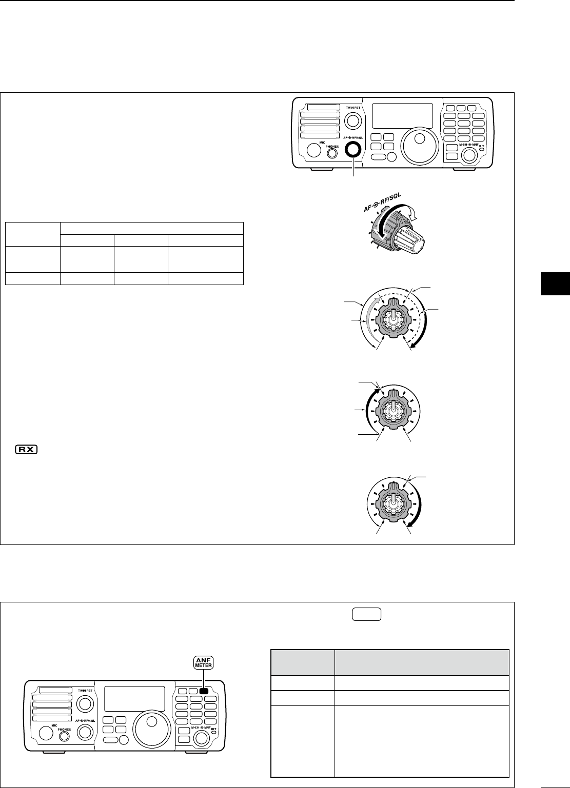
30
3
BASIC OPERATION
1
2
3
4
5
6
7
8
9
10
11
12
13
14
15
16
17
18
19
20
21
N RF gain and Squelch
N Meter function
The [RF/SQL] control adjusts the RF gain and
squelch threshold level. The squelch stops noise out-
put from the speaker (closed position) when no sig-
nal is received.
• The 12 o’clock position is recommended for any setting
of the [RF/SQL] control.
• The [RF/SQL] control can be set as the RF gain control
only (squelch is fixed open) or squelch control (RF gain is
fixed at maximum) in the set mode (p. 75). See the table
as below.
MODE SET MODE SETTING
AUTO SQL RF + SQL
SSB, CW
RTTY RF GAIN SQL RF GAIN + SQL
AM SQL SQL RF GAIN + SQL
M Adjusting RF gain (Receive sensitivity)
Normally, the [RF/SQL] control is set to the 12 o’clock
position.
Rotate the [RF/SQL] control to the 11 o’clock posi-
tion for maximum sensitivity.
• Rotate the [RF/SQL] control clockwise to increase, coun-
terclockwise to decrease the receiver sensitivity.
• The S-meter indicates receive sensitivity.
M Adjusting squelch (Removing non-signal noise)
Rotate the [RF/SQL] control clockwise until the noise
just disappears when no signal is being received.
• “ ” disappears.
• Rotate the [RF/SQL] control past the threshold point in-
vokes the S-meter squelch— this allows you to set the
minimum signal level needed to open the squelch.
• A segment appears in the S-meter to indicate the S-me-
ter squelch level.
MODE
TUNER
TS
FILTER
SPCH
V/M
A/B
SPLIT
M-CL
SCAN
SET
ATT
P
.
AMP
COMP
VOX
MNF
RIT
123
456
78
0
50
28
1814
10
21 24
=
7
3.5
1.8
F-INP
M-CH/RIT
ENT
BAND
GENE
9
.
AGC
MW
ANF
METER
NR
NB
[RF/SQL]
Minimum RF gain
Adjustable range
RF gain adjustable
range
Maximum RF gain
Maximum RF gain
Squelch is open. S-meter squelch
S-meter squelch
threshold
Squelch is open.
S-meter squelch
S-meter squelch
threshold
• When functioning as RF GAIN/SQL control
• When functioning as RF GAIN control
• When functioning as SQL control
Lowest Threshold Highest Threshold
The transceiver has 3 transmit meter functions for
your convenience. Select the desired meter from RF
power (Po), ALC and SWR.
MODE
TUNER
TS
FILTER
SPCH
V/M
A/B
SPLIT
M-CL
SCAN
SET
ATT
P
.
AMP
COMP
VOX
MNF
RIT
123
456
78
0
50
28
1814
10
21 24
=
7
3.5
1.8
F-INP
M-CH/RIT
ENT
BAND
GENE
9
.
AGC
MW
ANF
METER
NR
NB
±
Push and hold
ANF
METER
for 1 sec. to toggle between
RF power (Po), SWR and ALC.
• The display indication changes as the following table.
DISPLAY
INDICATION MEASUREMENT
Po Indicates the relative RF output power.
SWR
Indicates the SWR on the transmission line.
ALC
Indicates the ALC level. When the meter
movement shows the input signal level
exceeds the allowable level, the ALC lim-
its the RF power. In such cases, reduce
the MIC gain setting (see p. 31) in the
quick set mode.
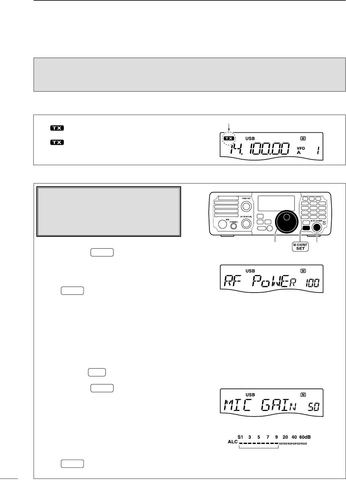
31
N Basic transmit operation
Before transmitting, monitor your selected oper-
ating frequency to make sure transmitting won’t
cause interference to other stations on the same
frequency.
It’s good Amateur practice to listen first. On the
HF bands, even if nothing is heard, ask “is the
frequency in use” once or twice, before you begin
operating on that frequency.
D Transmitting
q Push [PTT] (microphone) to transmit.
• “ ” appears.
w Release [PTT] (microphone) to return to receive.
• “ ” disappears.
Appears while transmitting
D Output power and Microphone gain settings
If a linear amplifier is connected such as the
IC-PW1/EURO, set the output power using the ALC
meter (see at “Microphone gain setting” as below)
to the ALC zone (ALC meter reading should be
within this zone), otherwise the linear amplifier will
not work properly.
M Output power setting
q Push and hold M-CH/RIT
SET for 1 sec. to enter the
quick set mode.
w Rotate [M-CH] to select “RF POWER.”
e Rotate [DIAL] to select the desired output setting.
• Output power is displayed in 101 steps (Low, 1–100.)
r Push M-CH/RIT
SET to exit the quick set mode and re-
turn to normal operation.
• Available power
SSB/CW/RTTY : 2–100 W
AM : 1–25 W* (*Carrier power)
M Microphone gain setting
Microphone gain must be adjusted properly so that
your signal does not distort when transmitted.
q Select SSB or AM mode.
w Push and hold ANF
METER for 1 sec. several times to
select the ALC meter.
e Push and hold M-CH/RIT
SET for 1 sec. to enter the
quick set mode.
r Rotate [M-CH] to select “MIC GAIN.”
t Push [PTT] (microphone) to transmit.
• Speak into the microphone at your normal voice level.
y While speaking into the microphone, rotate [DIAL]
so that the ALC meter reading does not go out-
side the ALC zone.
•
Microphone gain is adjusted in 1% steps (0% to 100%).
u Release [PTT] (microphone) to return to receive.
i Push M-CH/RIT
SET to exit the quick set mode and re-
turn to normal operation.
MODE
TUNER
TS
FILTER
SPCH
V/M
A/B
SPLIT
M-CL
SCAN
SET
ATT
P
.
AMP
COMP
VOX
MNF
RIT
123
456
78
0
50
28
1814
10
21 24
=
7
3.5
1.8
F-INP
M-CH/RIT
ENT
BAND
GENE
9
.
AGC
MW
ANF
METER
NR
NB
[M-CH][DIAL]
When maximum output power
“100” is selected (default)
When “50” is selected (default)
ALC zone
3BASIC OPERATION
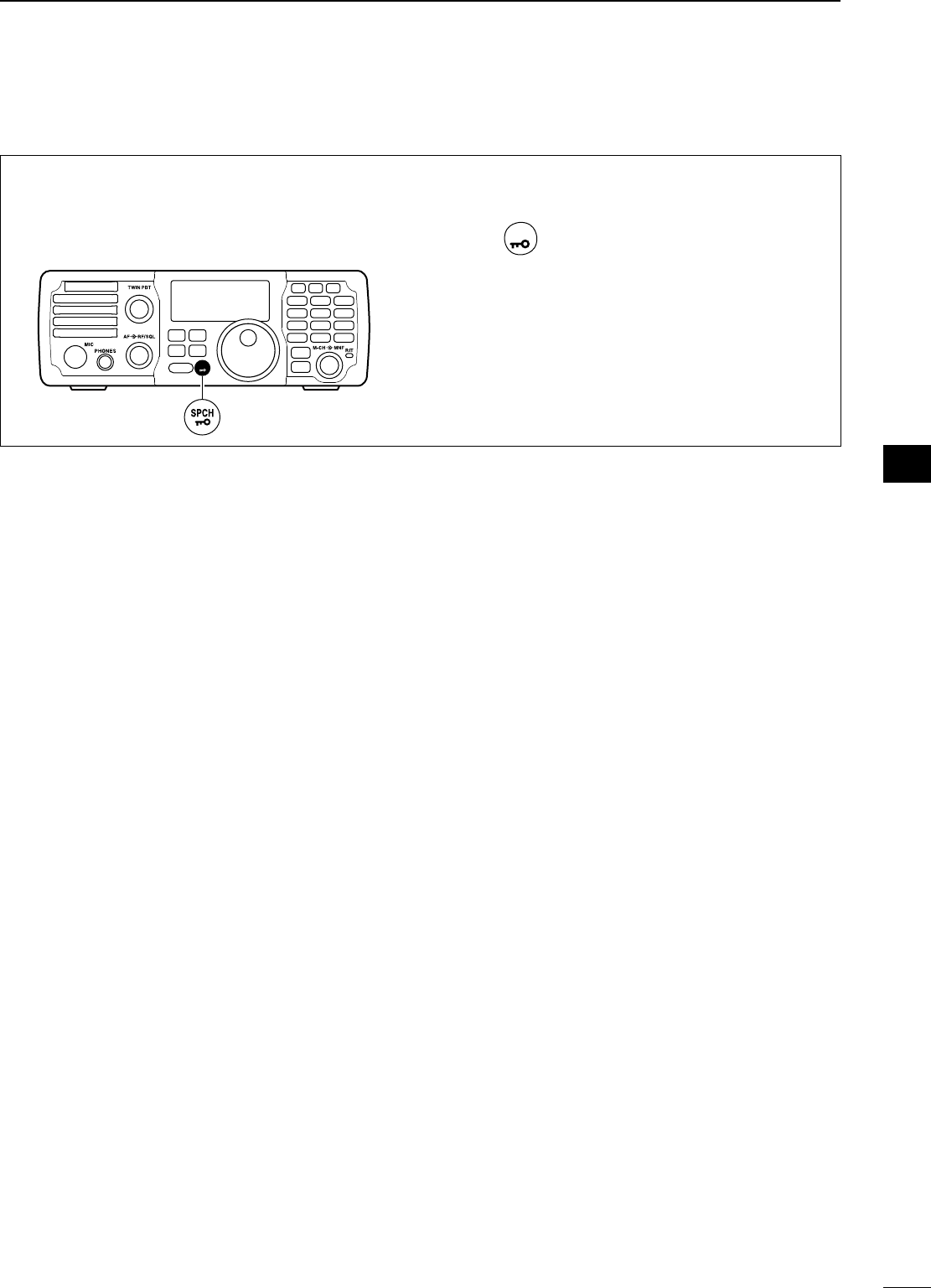
32
3
BASIC OPERATION
1
2
3
4
5
6
7
8
9
10
11
12
13
14
15
16
17
18
19
20
21
N Voice synthesizer function
The IC-7200 has a voice synthesizer. This function
announces the S-meter level, operating frequency
and mode (S-meter level’s announcement can be
deactivated—p. 77) in a clear, electronically gener-
ated voice, in English (or Japanese).
MODE
TUNER
TS
FILTER
SPCH
V/M
A/B
SPLIT
M-CL
SCAN
SET
ATT
P
.
AMP
COMP
VOX
MNF
RIT
123
456
78
0
50
28
1814
10
21 24
=
7
3.5
1.8
F-INP
M-CH/RIT
ENT
BAND
GENE
9
.
AGC
MW
ANF
METER
NR
NB
q Select the desired parameters to be announced,
such as Audio level, speed, language, contents, in
the set mode. (p. 77)
w Push
SPCH
to announce the selected contents.
• Push again to stop the announcement.
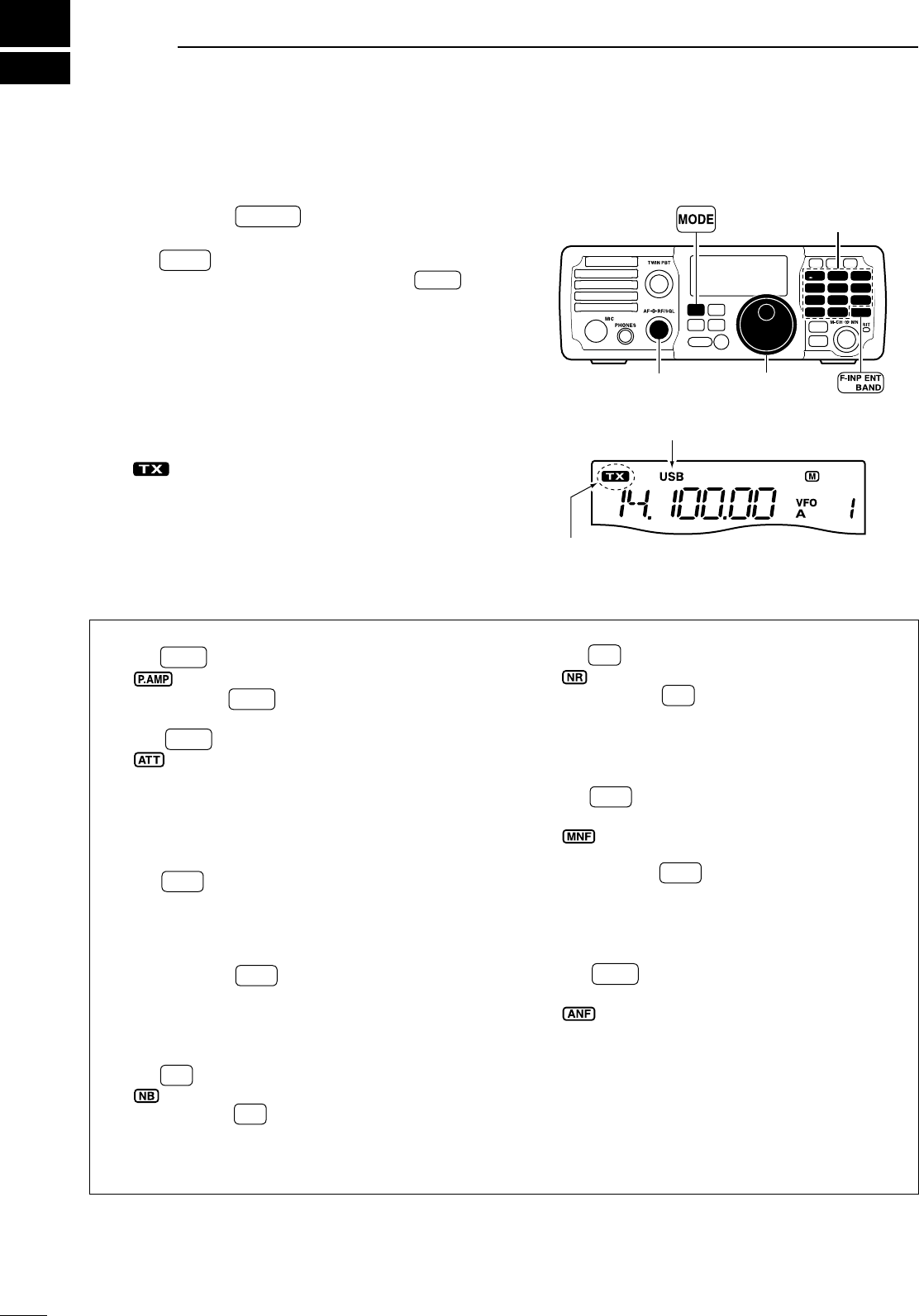
4
33
RECEIVE AND TRANSMIT
N Operating SSB
q Push and hold F-INP ENT
BAND for 1 sec., then push a
band key to select the desired band.
w Push MODE to select SSB mode.
• After SSB mode is selected, push and hold MODE for
1 sec. to toggle between LSB and USB modes.
• Below 10 MHz LSB is automatically selected; above
10 MHz USB is automatically selected.
e Rotate [DIAL] to tune in a desired signal.
• The S-meter indicates received signal strength when
a signal is received.
r Rotate the [AF] control to set audio to a comfort-
able listening level.
t Push [PTT] (microphone) to transmit.
• “ ” appears.
y Speak into the microphone at your normal voice
level.
• Adjust ‘MIC Gain’ at this step, if necessary. (p. 71)
u Release [PTT] (microphone) to return to receive.
MODE
TUNER
TS
FILTER
SPCH
V/M
A/B
SPLIT
M-CL
SCAN
SET
ATT
P
.
AMP
COMP
VOX
MNF
RIT
123
456
78
0
50
28
1814
10
21 24
=
7
3.5
1.8
F-INP
M-CH/RIT
ENT
BAND
GENE
9
.
AGC
MW
ANF
METER
NR
NB
Band keys
[DIAL]
[AF]
“USB” or “LSB” appears.
Appears while transmitting.
D Convenient functions for receive
• Preamp and attenuator (p. 45)
± Push P.AMP
ATT to turn the preamp ON or OFF.
• “ ” appears when the preamp is set to ON.
± Push and hold P.AMP
ATT for 1 sec. to turn the attenu-
ator ON.
• Push P.AMP
ATT to turn the attenuator OFF.
•
“” appears when the attenuator is set to ON.
• Twin PBT (passband tuning) (p. 46)
±Rotate [TWIN PBT] (controls–inner/outer).
• AGC (auto gain control) (p. 45)
± Push AGC once or twice to select the time con-
stant for the AGC circuit fast and slow.
• “F.AG C” appears when the fast time constant is se-
lected, and no indicator appears when the slow time
constant is selected, respectively.
± Push and hold AGC for 1 sec. to turn the AGC
function OFF.
• “AGC-OFF” appears on the display.
• Noise blanker (p. 49)
± Push NB to turn the noise blanker ON or OFF.
• “ ” appears when the noise blanker is set to ON.
± Push and hold NB for 1 sec. to enter the noise
blanker set mode, then rotate [DIAL] to adjust the
threshold level, or the blank time.
• Rotate [M-CH] to select an item.
• Noise reduction (p. 50)
± Push NR to turn the noise reduction ON or OFF.
• “ ” appears when the noise reduction is ON.
± Push and hold NR for 1 sec. to enter the noise
reduction level set mode, then rotate [DIAL] to
adjust the noise reduction level.
• Manual notch filter (pgs. 51, 52)
± Push MNF to turn the manual notch filter ON or
OFF.
•
“ ”
appears when the manual notch filter is set to
ON.
± Push and hold MNF for 1 sec. to enter the man-
ual notch filter set mode, then rotate [DIAL] to se-
lect the filter width from narrow, middle and wide.
• Auto notch filter (p. 51)
± Push ANF
METER to turn the auto notch filter ON or
OFF.
• “” appears when the auto notch filter is set to
ON.
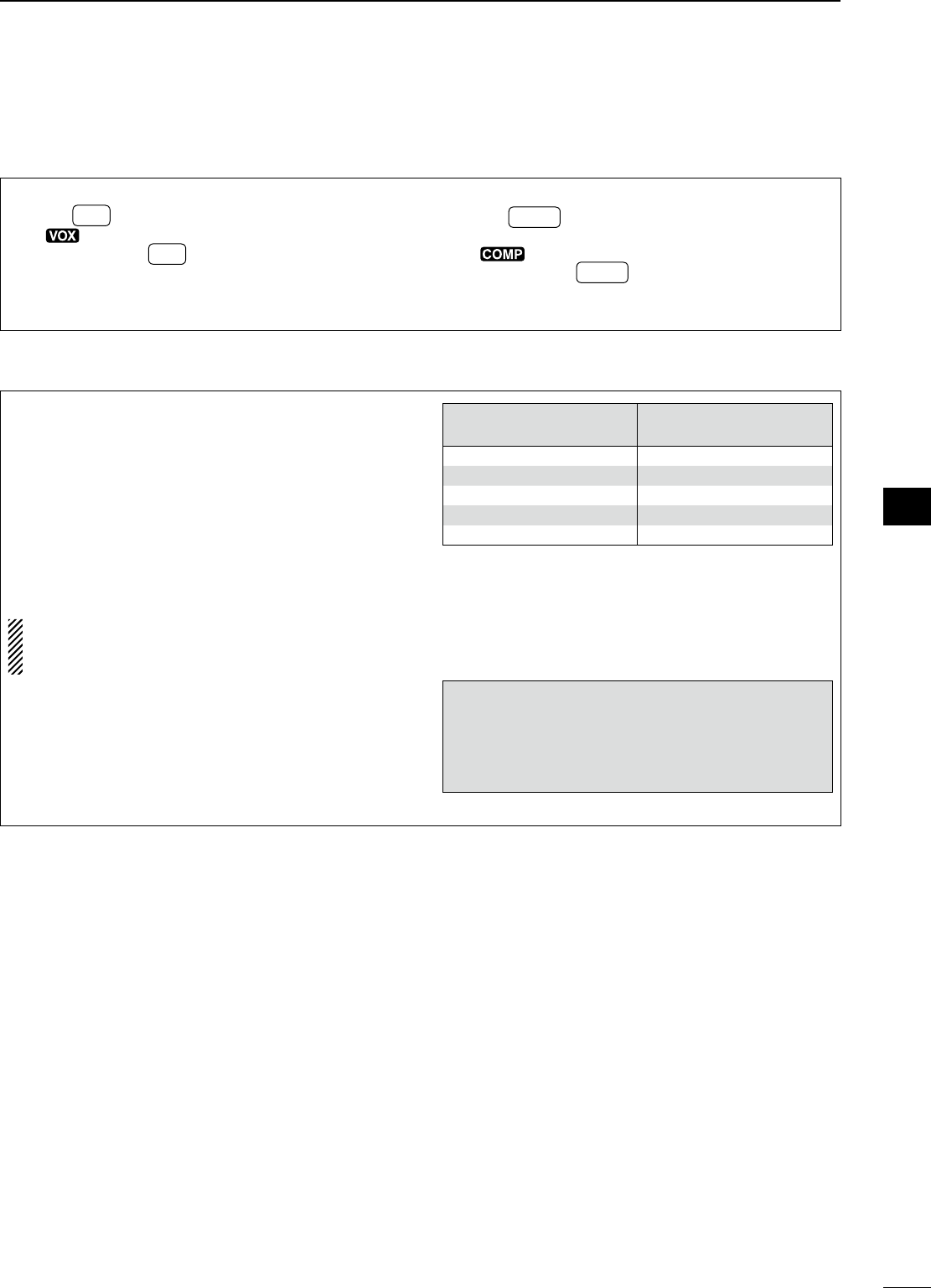
34
4
RECEIVE AND TRANSMIT
1
2
3
4
5
6
7
8
9
10
11
12
13
14
15
16
17
18
19
20
21
D Convenient functions for transmit
• VOX (voice operated transmit) (p. 53)
± Push VOX to turn the VOX function ON or OFF.
• “ ” appears when the VOX function is ON.
± Push and hold VOX for 1 sec. to enter the VOX
set mode, then rotate [DIAL] to adjust the VOX
gain, anti VOX gain or VOX delay.
• Rotate [M-CH] to select an item.
• Speech compressor (p. 57)
± Push COMP to turn the speech compressor ON
or OFF.
•
“” appears when the speech compressor is ON.
± Push and hold COMP for 1 sec. to enter the com-
pression level set mode, then rotate [DIAL] to ad-
just the compression level.
D About 5 MHz band operation (USA version only)
Operation on the 5 MHz band is allowed on 5 dis-
crete frequencies and must adhere to the following:
• USB mode
• Maximum of 50 watts ERP (Effective Radiated Power)
• 2.8 kHz bandwidth
It is the operator’s responsibility to set all controls so
that the transmission in this band meets the stringent
conditions under which we may use these frequen-
cies.
NOTE: We recommend that you store these fre-
quencies, mode and filter settings into the mem-
ory channel for easy recall.
IC-7200
Display Frequency*
FCC Channel
Center Frequency*
5.33050 MHz 5.33200 MHz
5.34650 MHz 5.34800 MHz
5.36650 MHz 5.36800 MHz
5.37150 MHz 5.37300 MHz
5.40350 MHz 5.40500 MHz
* The channel center frequencies that are specified
by the FCC, show the center frequency of their
passband. However, the IC-7200 displays carrier
point frequency, so set 1.5 kHz below from FCC
channel center frequency.
To assist you in operating the 5 MHz band cor-
rectly within the rules specified by the FCC,
transmission is impossible on any 5 MHz band
frequency other than the 5 frequencies indicated in
the table above.
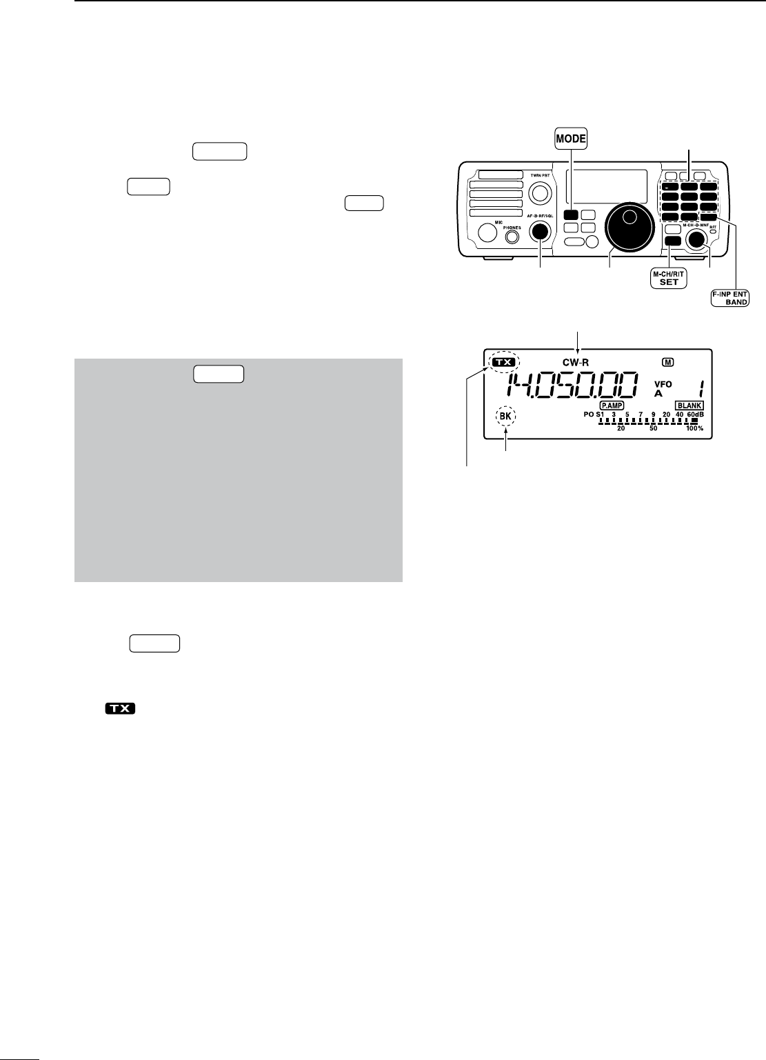
35
N Operating CW
q Connect a paddle or straight key as on page 18.
w Push and hold F-INP ENT
BAND for 1 sec., then push a
band key to select the desired band.
e Push MODE to select CW mode.
• After CW mode is selected, push and hold MODE for
1 sec. to toggle between CW and CW-R modes.
r Rotate [DIAL] to tune in a desired signal with the
desired tone frequency.
• The S-meter indicates received signal strength when
signal is received.
t Rotate the [AF] control to set audio to a comfort-
able listening level.
y Set CW break-in operation and the CW delay time
in the set mode. (p. 79)
q Push and hold M-CH/RIT
SET for 1 sec. twice to enter
the set mode.
w Rotate [M-CH] to select “BK-IN” to set the CW
break-in operation.
e Rotate [DIAL] to select the CW break-in opera-
tion from full break-in, semi break-in or OFF.
• FL : full break-in
• SE : semi break-in
• OF : break-in OFF
r Rotate [M-CH] to select “BK-DELAY” to select
the CW delay time when semi break-in operation
is selected in step e.
t Rotate [DIAL] to set the desired delay time.
u Continue to set the keyer settings in the set mode,
if necessary. (p. 80)
i Push M-CH/RIT
SET to exit the set mode and return to
normal operation.
o Keying to transmit, use the electric keyer, paddle or
straight key to send your CW signals.
• “ ” appears.
• The Po meter indicates transmitted CW signal strength.
!0 Stop keying to return to receive.
MODE
TUNER
TS
FILTER
SPCH
V/M
A/B
SPLIT
M-CL
SCAN
SET
ATT
P
.
AMP
COMP
VOX
MNF
RIT
123
456
78
0
50
28
1814
10
21 24
=
7
3.5
1.8
F-INP
M-CH/RIT
ENT
BAND
GENE
9
.
AGC
MW
ANF
METER
NR
NB
Band keys
[DIAL]
[AF]
“CW” or “CW-R” appears.
Appears while transmitting.
[M-CH]
Appears when semi break-in is selected.
4RECEIVE AND TRANSMIT
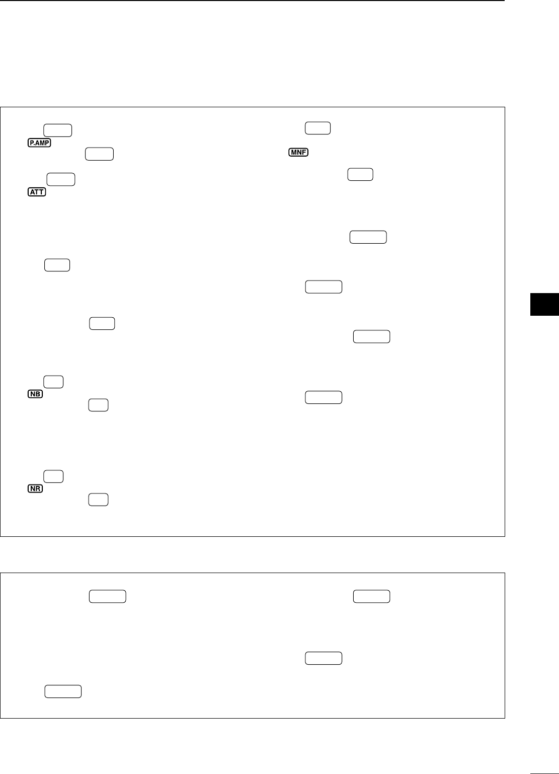
36
4
RECEIVE AND TRANSMIT
1
2
3
4
5
6
7
8
9
10
11
12
13
14
15
16
17
18
19
20
21
D Convenient functions for receive
• Preamp and attenuator (p. 45)
± Push P.AMP
ATT to turn the preamp ON or OFF.
• “ ” appears when the preamp is set to ON.
± Push and hold P.AMP
ATT for 1 sec. to turn the attenu-
ator ON.
• Push P.AMP
ATT to turn the attenuator OFF.
•
“” appears when the attenuator is set to ON.
• Twin PBT (passband tuning) (p. 46)
±Rotate [TWIN PBT] (controls–inner/outer).
• AGC (auto gain control) (p. 45)
± Push AGC once or twice to select the time con-
stant for the AGC circuit fast and slow.
• “F.AG C” appears when the fast time constant is se-
lected, and no indicator appears when the slow time
constant is selected, respectively.
± Push and hold AGC for 1 sec. to turn the AGC
function OFF.
• “AGC-OFF” appears on the display.
• Noise blanker (p. 49)
± Push NB to turn the noise blanker ON or OFF.
• “ ” appears when the noise blanker is set to ON.
± Push and hold NB for 1 sec. to enter the noise
blanker set mode, then rotate [DIAL] to adjust the
threshold level, or the blank time.
• Rotate [M-CH] to select an item.
• Noise reduction (p. 50)
± Push NR to turn the noise reduction ON or OFF.
• “ ” appears when the noise reduction is ON.
± Push and hold NR for 1 sec. to enter the noise
reduction level set mode, then rotate [DIAL] to
adjust the noise reduction level.
• Manual notch filter (pgs. 51, 52)
± Push MNF to turn the manual notch filter ON or
OFF.
•
“ ”
appears when the manual notch filter is set to
ON.
± Push and hold MNF for 1 sec. to enter the man-
ual notch filter set mode, then rotate [DIAL] to se-
lect the filter width from narrow, middle and wide.
• ¼ function (p. 78)
q Push and hold M-CH/RIT
SET for 1 sec. twice to enter
the set mode.
w Rotate [M-CH] to select “DIAL ¼”.
e Rotate [DIAL] to turn the 1⁄4 function ON or OFF.
r Push M-CH/RIT
SET to exit the set mode and return to
normal operation.
• CW pitch control (p. 37)
q Push and hold M-CH/RIT
SET for 1 sec. to enter the
quick set mode.
w Rotate [M-CH] to select “CW PITCH”.
e Rotate [DIAL] to set the desired CW pitch from
300 to 900 Hz in 10 Hz steps.
r Push M-CH/RIT
SET to exit the quick set mode and re-
turn to normal operation.
D Convenient functions for transmit
• Break-in function (p. 55)
q Push and hold M-CH/RIT
SET for 1 sec. twice to enter
the set mode.
w Rotate [M-CH] to select “BK-IN”.
e Rotate [DIAL] to select the CW break-in operation
from full break-in, semi break-in or OFF.
• FL : Full break-in
• SE : Semi break-in
• OF : Break-in OFF
r Push M-CH/RIT
SET to exit the set mode and return to
normal operation.
• Keying speed setting (p. 38)
q Push and hold M-CH/RIT
SET for 1 sec. to enter the
quick set mode.
w Rotate [M-CH] to select “KEY SPD”.
e Rotate [DIAL] to adjust the CW key speed from 6
to 60 wpm.
r Push M-CH/RIT
SET to exit the quick set mode and re-
turn to normal operation.
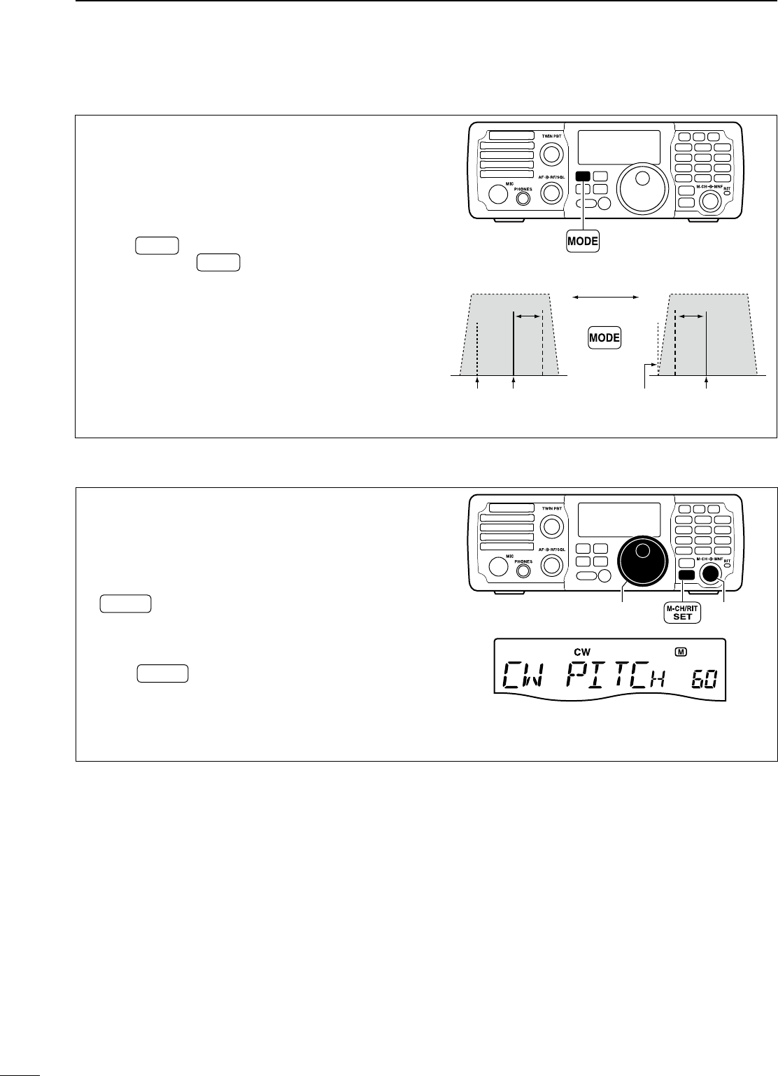
37
D CW reverse mode
The CW-R (CW Reverse) mode receives CW signals
on the reverse sideband like that of LSB and USB
modes.
Use when interference is near the desired signal and
you want to shift the tone of the interfering signal.
q Push MODE several times to select CW mode.
w
Push and hold
MODE
for 1 sec. to select CW or
CW-R mode.
• Check the interference tone.
• Receive audio tone response
CW-R mode (USB side)CW mode (LSB side)
BFO
600 Hz
Desired signalInteference Desired signal
600 Hz
BFO
Inteference
Push and hold
for 1 sec.
MODE
TUNER
TS
FILTER
SPCH
V/M
A/B
SPLIT
M-CL
SCAN
SET
ATT
P
.
AMP
COMP
VOX
MNF
RIT
123
456
78
0
50
28
1814
10
21 24
=
7
3.5
1.8
F-INP
M-CH/RIT
ENT
BAND
GENE
9
.
AGC
MW
ANF
METER
NR
NB
D CW pitch control
The received CW audio pitch and monitored CW
audio pitch can be adjusted to suit your preferences
(300 to 900 Hz) without changing the operating fre-
quency.
q
When CW (CW-R) mode is selected, push and hold
M-CH/RIT
SET
for 1 sec. to enter the quick set mode.
w Rotate [M-CH] to select “CW PITCH”, then rotate
[DIAL] to set the desired pitch.
• CW pitch is adjusted in 10 Hz steps (300 to 900 Hz).
e Push M-CH/RIT
SET to exit the quick set mode and re-
turn to normal operation.
MODE
TUNER
TS
FILTER
SPCH
V/M
A/B
SPLIT
M-CL
SCAN
SET
ATT
P
.
AMP
COMP
VOX
MNF
RIT
123
456
78
0
50
28
1814
10
21 24
=
7
3.5
1.8
F-INP
M-CH/RIT
ENT
BAND
GENE
9
.
AGC
MW
ANF
METER
NR
NB
[DIAL] [M-CH]
This shows the default setting for
the CW pitch control (600 Hz).
4RECEIVE AND TRANSMIT
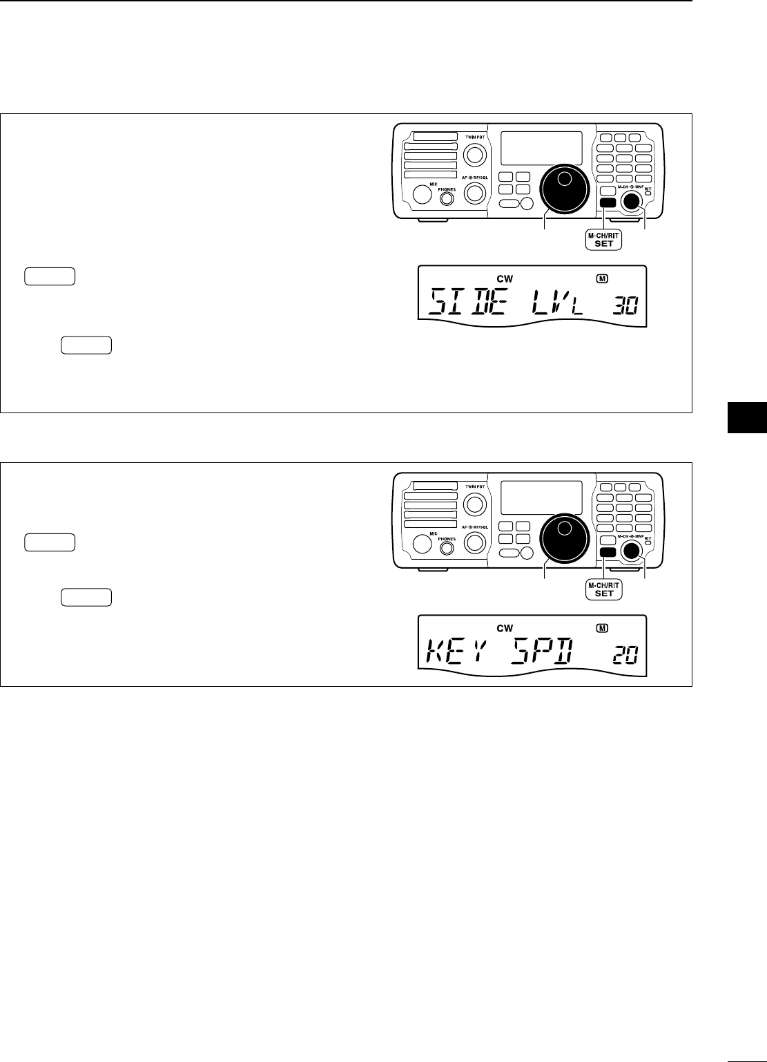
38
4
RECEIVE AND TRANSMIT
1
2
3
4
5
6
7
8
9
10
11
12
13
14
15
16
17
18
19
20
21
D CW side tone function
When the transceiver is in receive (and the break-in
function is OFF— pgs. 55, 56) you can listen to the
tone of your CW signal without actually transmitting.
This allows you to spot your transmit signal exactly
compared to another station’s. This also convenient
for CW practice.
q
When CW (CW-R) mode is selected, push and hold
M-CH/RIT
SET
for 1 sec. to enter the quick set mode.
w Rotate [M-CH] to select “SIDE LVL”, then rotate
[DIAL] to adjust the side tone level.
• Side tone level is adjusted in 1% steps (0% to 100%).
e Push M-CH/RIT
SET to exit the quick set mode and re-
turn to normal operation.
MODE
TUNER
TS
FILTER
SPCH
V/M
A/B
SPLIT
M-CL
SCAN
SET
ATT
P
.
AMP
COMP
VOX
MNF
RIT
123
456
78
0
50
28
1814
10
21 24
=
7
3.5
1.8
F-INP
M-CH/RIT
ENT
BAND
GENE
9
.
AGC
MW
ANF
METER
NR
NB
[DIAL] [M-CH]
D Keying speed setting
The transceiver’s internal electronic keyer speed can
be adjusted from 6 to 60 wpm.
q
When CW (CW-R) mode is selected, push and hold
M-CH/RIT
SET
for 1 sec. to enter the quick set mode.
w Rotate [M-CH] to select “KEY SPD”, then rotate
[DIAL] to adjust the keying speed.
e Push M-CH/RIT
SET to exit the quick set mode and re-
turn to normal operation.
MODE
TUNER
TS
FILTER
SPCH
V/M
A/B
SPLIT
M-CL
SCAN
SET
ATT
P
.
AMP
COMP
VOX
MNF
RIT
123
456
78
0
50
28
1814
10
21 24
=
7
3.5
1.8
F-INP
M-CH/RIT
ENT
BAND
GENE
9
.
AGC
MW
ANF
METER
NR
NB
[DIAL] [M-CH]
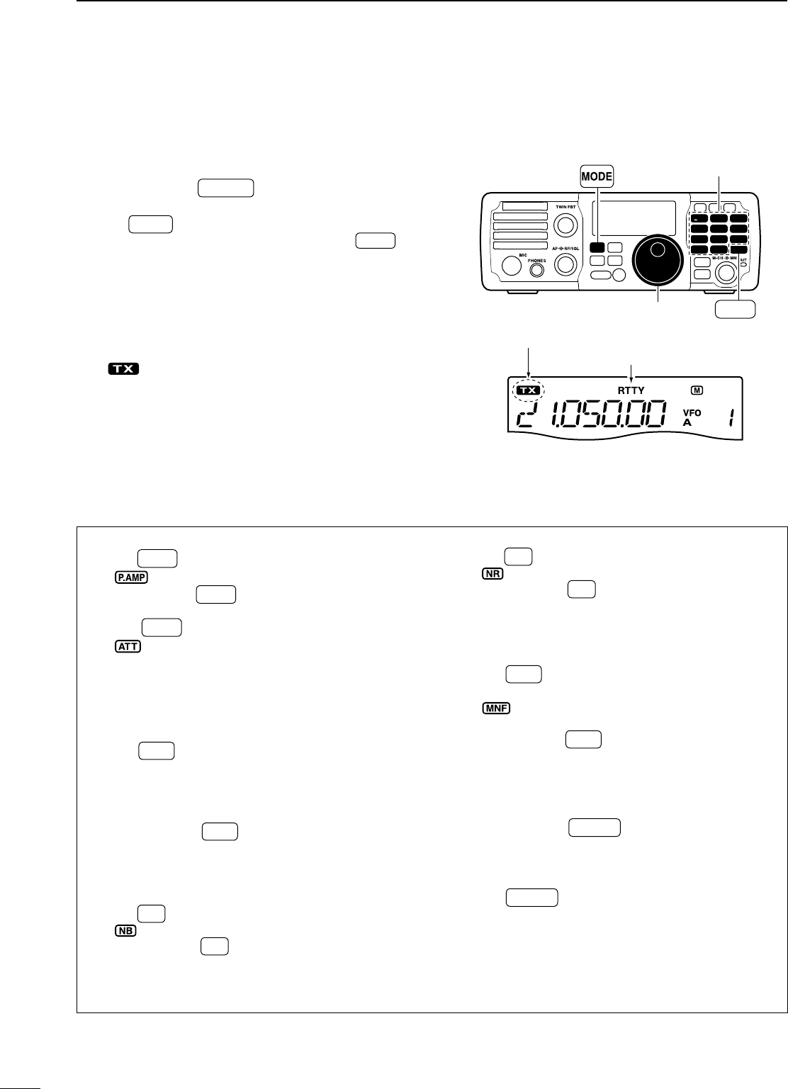
39
4RECEIVE AND TRANSMIT
NOperating RTTY (FSK)
When using your RTTY terminal or TNC, consult the
manual that comes with the RTTY terminal or TNC.
q Push and hold F-INP ENT
BAND for 1 sec., then push a
band key to select the desired band.
w Push MODE to select RTTY mode.
• After RTTY mode is selected, push and hold MODE for
1 sec. to toggle between RTTY and RTTY-R modes.
e Rotate [DIAL] to tune in a desired signal.
• The S-meter indicates received signal strength when
signal is received.
• If the received signal cannot be demodulated, try se-
lecting RTTY-R mode (or RTTY mode).
r Transmit a SEND signal from your TNC.
• “ ” appears.
• The Po meter indicates the transmitted RTTY signal
strength.
t Use the connected PC or TNC (TU) to transmit
RTTY (FSK) signals.
MODE
TUNER
TS
FILTER
SPCH
V/M
A/B
SPLIT
M-CL
SCAN
SET
ATT
P
.
AMP
COMP
VOX
MNF
RIT
123
456
78
0
50
28
1814
10
21 24
=
7
3.5
1.8
F-INP
M-CH/RIT
ENT
BAND
GENE
9
.
AGC
MW
ANF
METER
NR
NB
Band keys
[DIAL]
“RTTY” or “RTTY-R” appears.
F-INP ENT
BAND
Appears while transmitting.
D Convenient functions for receive
• Preamp and attenuator (p. 45)
± Push P.AMP
ATT to turn the preamp ON or OFF.
• “ ” appears when the preamp is set to ON.
± Push and hold P.AMP
ATT for 1 sec. to turn the attenu-
ator ON.
• Push P.AMP
ATT to turn the attenuator OFF.
•
“” appears when the attenuator is set to ON.
• Twin PBT (passband tuning) (p. 46)
±Rotate [TWIN PBT] (controls–inner/outer).
• AGC (auto gain control) (p. 45)
± Push AGC once or twice to select the time con-
stant for the AGC circuit fast and slow.
• “F.AG C” appears when the fast time constant is se-
lected, and no indicator appears when the slow time
constant is selected, respectively.
± Push and hold AGC for 1 sec. to turn the AGC
function OFF.
• “AGC-OFF” appears on the display.
• Noise blanker (p. 49)
± Push NB to turn the noise blanker ON or OFF.
• “ ” appears when the noise blanker is set to ON.
± Push and hold NB for 1 sec. to enter the noise
blanker set mode, then rotate [DIAL] to adjust the
threshold level, or the blank time.
• Rotate [M-CH] to select an item.
• Noise reduction (p. 50)
± Push NR to turn the noise reduction ON or OFF.
• “ ” appears when the noise reduction is ON.
± Push and hold NR for 1 sec. to enter the noise
reduction level set mode, then rotate [DIAL] to
adjust the noise reduction level.
• Manual notch filter (pgs. 51, 52)
± Push MNF to turn the manual notch filter ON or
OFF.
•
“ ”
appears when the manual notch filter is set to
ON.
± Push and hold MNF for 1 sec. to enter the man-
ual notch filter set mode, then rotate [DIAL] to se-
lect the filter width from narrow, middle and wide.
• ¼ function (p. 78)
q Push and hold M-CH/RIT
SET for 1 sec. twice to enter
the set mode.
w Rotate [M-CH] to select “DIAL ¼”.
e Rotate [DIAL] to turn the 1⁄4 function ON or OFF.
r Push M-CH/RIT
SET to exit the set mode and return to
normal operation.
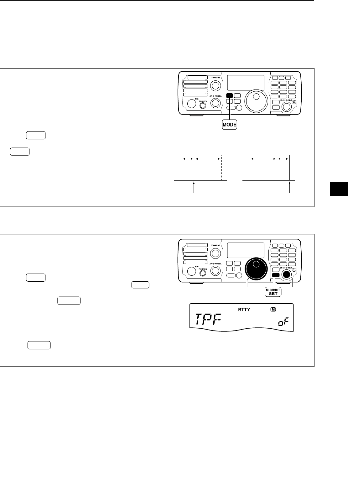
40
4
RECEIVE AND TRANSMIT
1
2
3
4
5
6
7
8
9
10
11
12
13
14
15
16
17
18
19
20
21
D RTTY reverse mode
Received characters are occasionally garbled when
the receive signal is reversed between MARK and
SPACE. This reversal can be caused by incorrect
TNC connections, settings, commands, etc.
To receive a reversed RTTY signal correctly, select
RTTY-R (RTTY reverse) mode.
q Push MODE to select RTTY mode.
w After RTTY mode is selected, push and hold
MODE for 1 sec. to toggle between RTTY and
RTTY-R modes.
MODE
TUNER
TS
FILTER
SPCH
V/M
A/B
SPLIT
M-CL
SCAN
SET
ATT
P
.
AMP
COMP
VOX
MNF
RIT
123
456
78
0
50
28
1814
10
21 24
=
7
3.5
1.8
F-INP
M-CH/RIT
ENT
BAND
GENE
9
.
AGC
MW
ANF
METER
NR
NB
ReverseNormal
BFO
170
Hz
2125
Hz
170
Hz
2125
Hz
BFO
Mark
Space
Displayed freq.
Displayed freq.
Mark
Space
D Twin peak filter
The twin peak filter changes the receive frequency
response by boosting two particular frequencies
(2125 and 2295 Hz) for better copying of desired RTTY
signals.
q Push MODE to select RTTY mode.
•
After RTTY mode is selected, push and hold
MODE
for 1 sec. to toggle between RTTY and RTTY-R modes.
w Push and hold M-CH/RIT
SET for 1 sec. to enter the
quick set mode.
e Rotate [M-CH] to select “TPF”, then rotate [DIAL]
to select the twin peak filter function ON or OFF.
• The received audio volume may become greater when
the twin peak filter is turned ON.
r Push M-CH/RIT
SET to exit the quick set mode and re-
turn to normal operation.
OFF (default)
MODE
TUNER
TS
FILTER
SPCH
V/M
A/B
SPLIT
M-CL
SCAN
SET
ATT
P
.
AMP
COMP
VOX
MNF
RIT
123
456
78
0
50
28
1814
10
21 24
=
7
3.5
1.8
F-INP
M-CH/RIT
ENT
BAND
GENE
9
.
AGC
MW
ANF
METER
NR
NB
[DIAL] [M-CH]
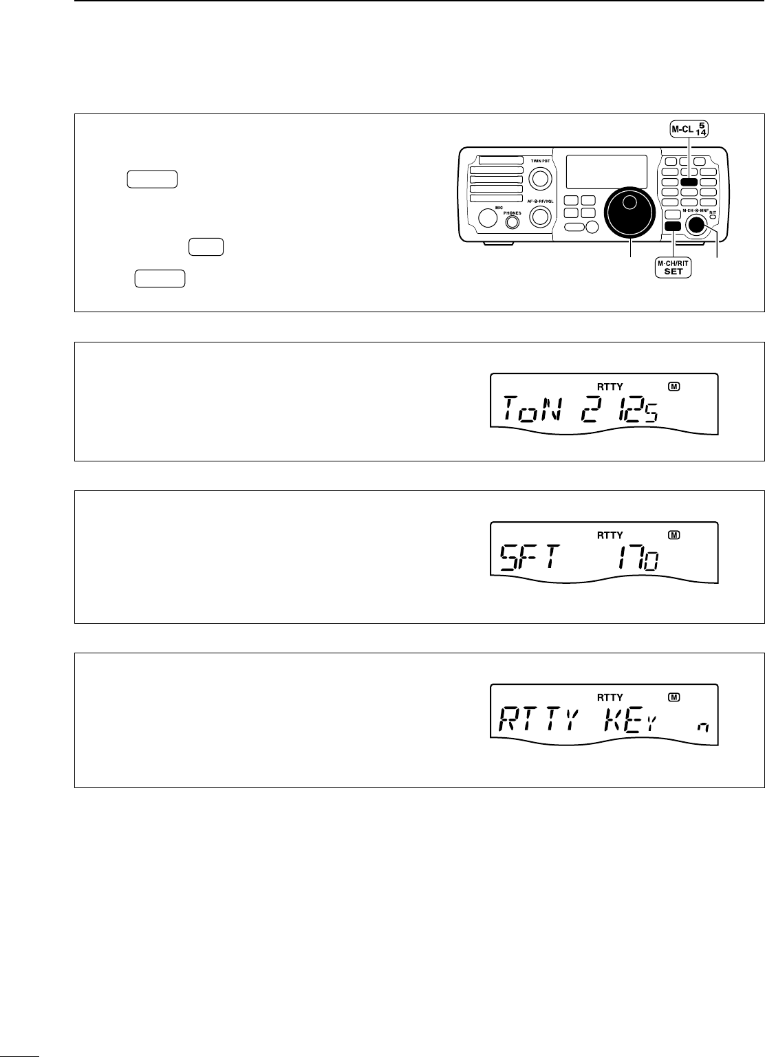
41
4RECEIVE AND TRANSMIT
D RTTY decode set mode
Set the RTTY key polarity, shift width and mark tone.
q
When RTTY (RTTY-R) mode is selected, push and
hold
M-CH/RIT
SET
for 1 sec. to enter the quick set mode.
w Rotate [M-CH] to select the desired set item.
e Rotate [DIAL] to adjust the desired value or con-
dition.
• Push and hold M-CL for 1 sec. to return to the default
value.
r Push M-CH/RIT
SET to exit the quick set mode and re-
turn to normal operation.
[DIAL]
MODE
TUNER
TS
FILTER
SPCH
V/M
A/B
SPLIT
M-CL
SCAN
SET
ATT
P
.
AMP
COMP
VOX
MNF
RIT
123
456
78
0
50
28
1814
10
21 24
=
7
3.5
1.8
F-INP
M-CH/RIT
ENT
BAND
GENE
9
.
AGC
MW
ANF
METER
NR
NB
[M-CH]
RTTY mark tone (RTTY mode)
This item selects the RTTY mark frequency. RTTY mark
frequency is switched between 1275, 1615 and 2125 Hz.
2125 Hz
(
default
)
RTTY shift width (RTTY mode)
This item adjusts the RTTY shift width. There are 4
selectable values: 170, 200, 425 and 850 Hz.
170 Hz
(
default
)
RTTY key polarity (RTTY mode)
This item selects the RTTY keying polarity. Normal or
reverse keying polarity can be selected.
When reverse polarity is selected, Mark and Space are
reversed.
n (normal) : Key open/close = Mark/Space
r (reverse) : Key open/close = Space/Mark
NORMAL
(
default
)
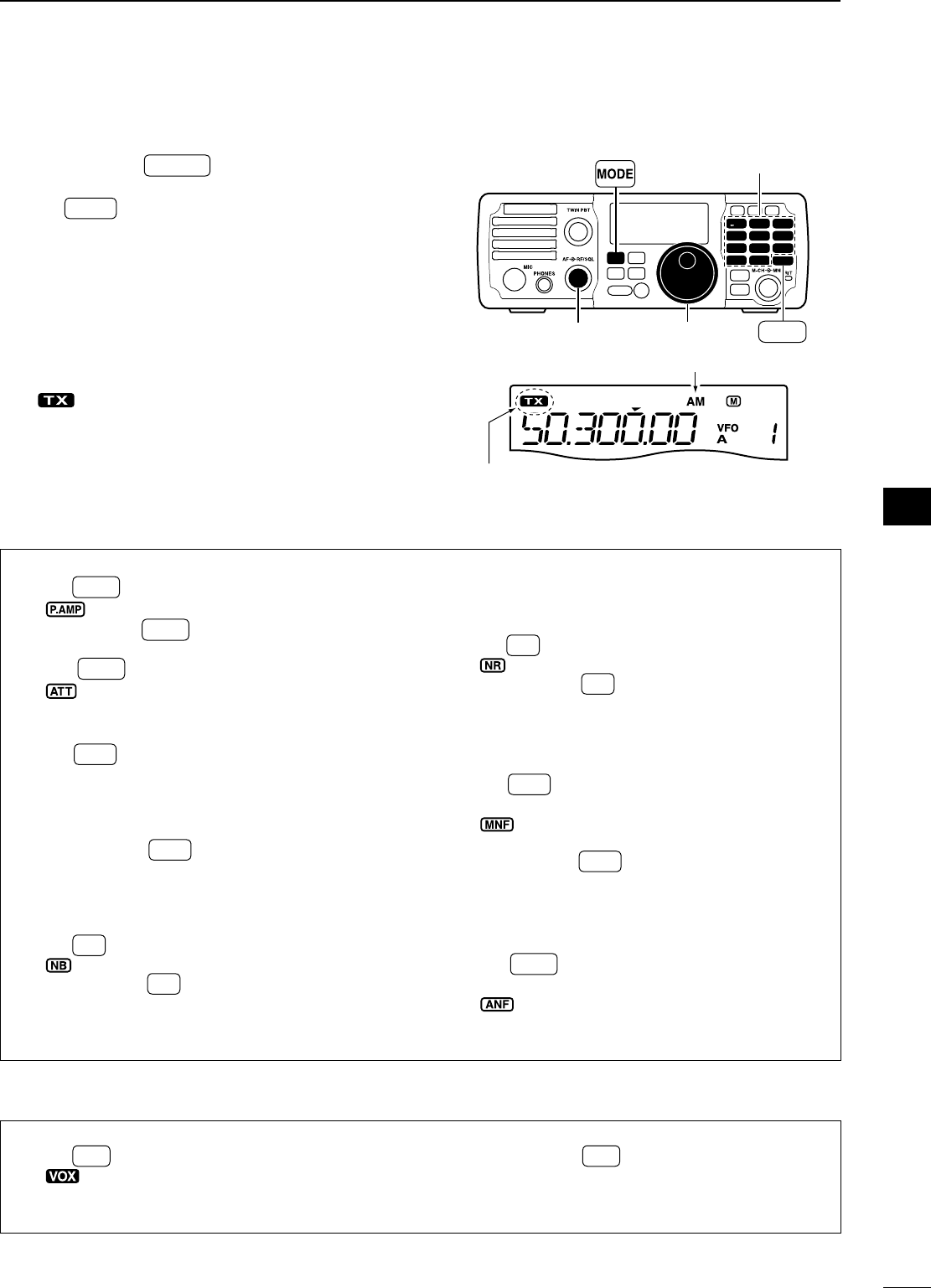
42
4
RECEIVE AND TRANSMIT
1
2
3
4
5
6
7
8
9
10
11
12
13
14
15
16
17
18
19
20
21
N Operating AM
q Push and hold F-INP ENT
BAND for 1 sec., then push a
band key to select the desired band.
w Push MODE to select AM mode.
e Rotate [DIAL] to tune in a desired signal.
• The S-meter indicates received signal strength when a
signal is received.
• The default tuning step for AM mode is 1 kHz; this
can be changed using the tuning step program mode.
(p. 26)
r Rotate the [AF] control to set audio to a comfort-
able listening level.
t Push [PTT] (microphone) to transmit.
• “ ” appears.
y Speak into the microphone at your normal voice
level.
• Adjust ‘MIC Gain’ at this step, if necessary. (p. 71)
u Release [PTT] (microphone) to return to receive.
MODE
TUNER
TS
FILTER
SPCH
V/M
A/B
SPLIT
M-CL
SCAN
SET
ATT
P
.
AMP
COMP
VOX
MNF
RIT
123
456
78
0
50
28
1814
10
21 24
=
7
3.5
1.8
F-INP
M-CH/RIT
ENT
BAND
GENE
9
.
AGC
MW
ANF
METER
NR
NB
[DIAL]
[AF]
Appears while transmitting.
F-INP ENT
BAND
Band keys
“AM” appears.
D Convenient functions for receive
• Preamp and attenuator (p. 45)
± Push P.AMP
ATT to turn the preamp ON or OFF.
• “ ” appears when the preamp is set to ON.
± Push and hold P.AMP
ATT for 1 sec. to turn the attenu-
ator ON.
• Push P.AMP
ATT to turn the attenuator OFF.
•
“” appears when the attenuator is set to ON.
• AGC (auto gain control) (p. 45)
± Push AGC once or twice to select the time con-
stant for the AGC circuit fast and slow.
• “F.AG C” appears when the fast time constant is se-
lected, and no indicator appears when the slow time
constant is selected, respectively.
± Push and hold AGC for 1 sec. to turn the AGC
function OFF.
• “AGC-OFF” appears on the display.
• Noise blanker (p. 49)
± Push NB to turn the noise blanker ON or OFF.
• “ ” appears when the noise blanker is set to ON.
± Push and hold NB for 1 sec. to enter the noise
blanker set mode, then rotate [DIAL] to adjust the
threshold level, or the blank time.
• Rotate [M-CH] to select an item.
• Twin PBT (passband tuning) (p. 46)
±Rotate [TWIN PBT] (controls–inner/outer).
• Noise reduction (p. 50)
± Push NR to turn the noise reduction ON or OFF.
• “ ” appears when the noise reduction is ON.
± Push and hold NR for 1 sec. to enter the noise
reduction level set mode, then rotate [DIAL] to
adjust the noise reduction level.
• Manual notch filter (pgs. 51, 52)
± Push MNF to turn the manual notch filter ON or
OFF.
•
“ ”
appears when the manual notch filter is set to
ON.
± Push and hold MNF for 1 sec. to enter the man-
ual notch filter set mode, then rotate [DIAL] to se-
lect the filter width from narrow, middle and wide.
• Auto notch filter (p. 51)
± Push ANF
METER to turn the auto notch filter ON or
OFF.
• “” appears when the auto notch filter is set to
ON.
D Convenient functions for transmit
• VOX (voice operated transmit) (p. 53)
± Push VOX to turn the VOX function ON or OFF.
• “ ” appears when the VOX function is ON.
± Push and hold VOX for 1 sec. to enter the VOX
set mode, then rotate [DIAL] to adjust the VOX
gain, anti VOX gain or VOX delay.
• Rotate [M-CH] to select an item.
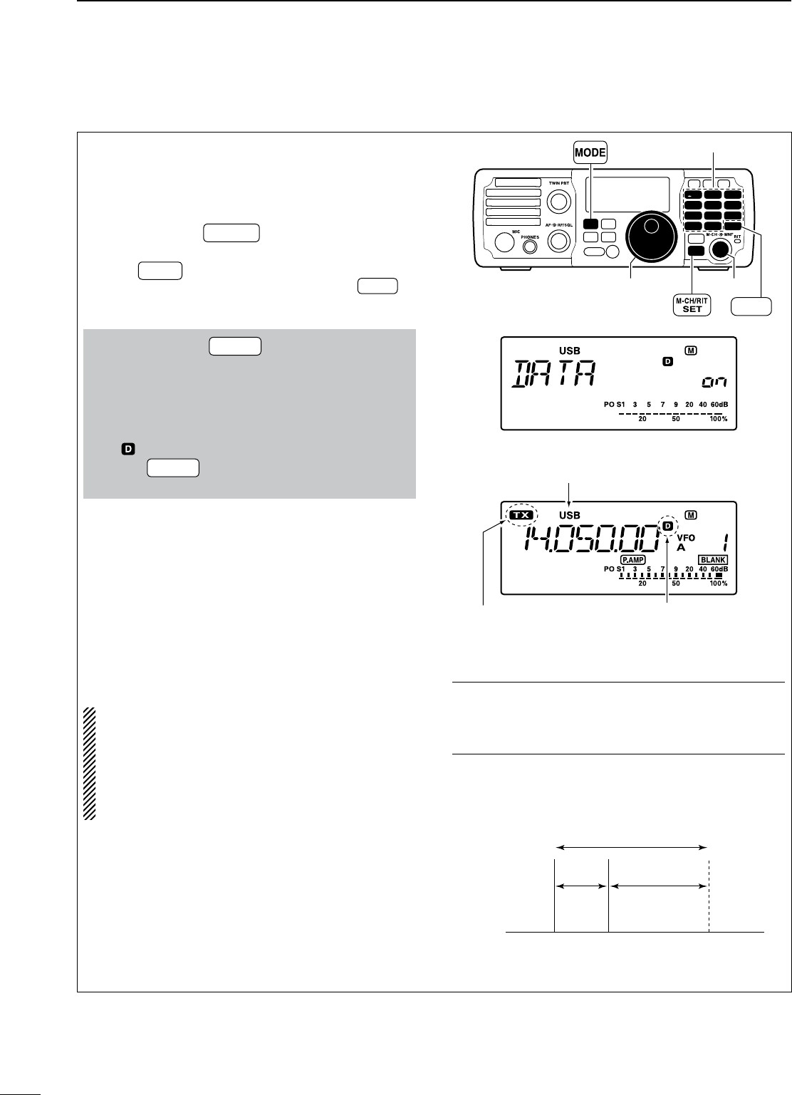
43
4RECEIVE AND TRANSMIT
N Data mode (SSTV/PSK31) operation
When operating SSTV or PSK31 with your PC soft-
ware, consult the manual that is supplied with the
software.
q Connect a PC to the transceiver. (p. 20)
w Push and hold F-INP ENT
BAND for 1 sec., then push a
band key to select the desired band.
e Push MODE to select SSB or AM mode.
• After SSB mode is selected, push and hold MODE for
1 sec. to toggle between USB and LSB modes.
r Turn data mode ON in the quick set mode.
q Push and hold M-CH/RIT
SET for 1 sec. to enter the
quick set mode.
w Rotate [M-CH] to select “DATA” to set the data
mode.
e Rotate [DIAL] to select the data mode ON or
OFF.
• “ ” appears when the data mode is turned ON.
r Push M-CH/RIT
SET to exit the quick set mode and
return to normal operation.
t Rotate [DIAL] to tune in a desired signal and de-
coded correctly.
• The S-meter indicates received signal strength when
a signal is received.
• Also use the tuning indicator of the software.
• During SSB data mode, ¼ tuning function can be
used for critical tuning.
y Use the PC (software) to transmit.
• When operating in SSB data mode, adjust the AF
output level from PC so that the ALC meter reading
doesn’t go outside the ALC zone.
NOTE: When the data mode is selected, the
audio input from the [ACC] connector* is used for
transmission instead of [MIC] connector.
The speech compressor function is turned OFF
for the SSB data mode transmission.
* The desired connector can be selected in the set
mode. (p. 77)
MODE
TUNER
TS
FILTER
SPCH
V/M
A/B
SPLIT
M-CL
SCAN
SET
ATT
P
.
AMP
COMP
VOX
MNF
RIT
123
456
78
0
50
28
1814
10
21 24
=
7
3.5
1.8
F-INP
M-CH/RIT
ENT
BAND
GENE
9
.
AGC
MW
ANF
METER
NR
NB
[DIAL] [M-CH]
Data mode: ON (default: OFF)
F-INP ENT
BAND
Band keys
Either “USB” or “LSB” appears.
Appears while transmitting. Appears
For your information
Carrier point frequency is displayed when SSB data
mode is selected.
See the diagram below for the tone-pair example.
• Example— LSB/LSB data mode
Mark freq.: 2125 Hz
Shift freq.: 200 Hz
2325 Hz
200 Hz 2125 Hz
Carrier
(Displayed frequency)
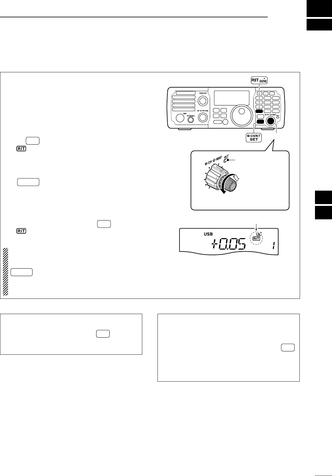
5
44
FUNCTIONS FOR RECEIVE
1
2
3
4
5
6
7
8
9
10
11
12
13
14
15
16
17
18
19
20
21
N RIT function
The RIT (Receive Incremental Tuning) function com-
pensates for stations transmitting off-frequency or
when you prefer to listen to slightly different-sound-
ing voice characteristics, etc.
The function shifts the receive frequency up to
±9.999 kHz in 1 Hz steps (10 Hz steps when cancel-
ling the 1 Hz step readout) without moving the trans-
mit frequency.
q Push RIT to turn the RIT function ON.
• “ ” and the shift frequency are indicated.
-
The shift frequency is indicated for approx. 1 sec.,
then returns to the operating frequency.
• The
RIT control indicator lights red.
-
If the RIT control indicator does not light, push
M-CH/RIT
SET . (See below for details)
w Rotate the [M-CH] control to compensate for off-
frequency stations.
• The transmit frequency is not shifted.
• The shift frequency is indicated for about 1 sec. when
rotating the [M-CH] control.
e To cancel the RIT function, push RIT again.
• “ ” disappears.
• The RIT control indicator goes out.
About the [M-CH] control:
The [M-CH] control selects the memory channel
and also shifts the RIT frequency. Pushing
M-CH/RIT
SET toggles the [M-CH] control as M-CH
selector or RIT controller.
RIT controller: RIT control indicator lights red.
M-CH selector: RIT control indicator goes out.
Shifting frequency
decreases
Shifting frequency
increases
RIT control indicator
lights red.
MODE
TUNER
TS
FILTER
SPCH
V/M
A/B
SPLIT
M-CL
SCAN
SET
ATT
P
.
AMP
COMP
VOX
MNF
RIT
123
456
78
0
50
28
1814
10
21 24
=
7
3.5
1.8
F-INP
M-CH/RIT
ENT
BAND
GENE
9
.
AGC
MW
ANF
METER
NR
NB
[M-CH]
Appears
• RIT monitor function
When the XFC (transmit frequency check function)
is ON (p. 76), pushing and holding RIT allows you
to monitor the operating frequency directly (RIT is
temporarily cancelled).
• Calculate function
The shift frequency of the RIT function can be
added/subtracted to the displayed frequency.
When the RIT function is ON, push and hold RIT *
for 1 sec.
• The RIT frequency is automatically reset.
* Available only when the XFC (transmit frequency check
function) is turned OFF. (p. 76)
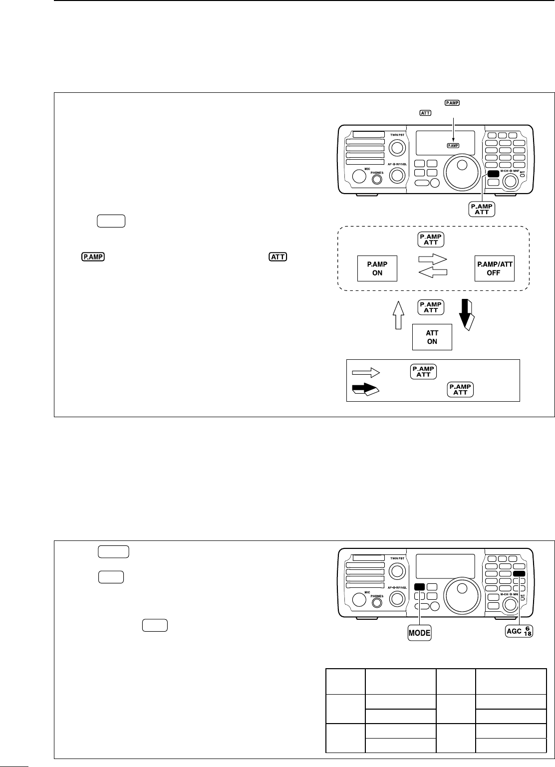
N Preamp and attenuator
The preamp amplifies received signals in the re-
ceiver input (front end) circuit to improve the S/N
ratio and sensitivity. Turn this function ON when re-
ceiving weak signals.
The attenuator prevents very strong signals near the
desired frequency, such as nearby broadcast sta-
tions or very strong amateur signals, from causing
distortion of a desired signal.
±
Push
P.AMP
ATT
momentarily to turn the preamp ON
and OFF; push and hold for 1 sec. to turn the
attenuator ON.
• “” appears when the preamp is ON; “ ”
appears when the 20 dB attenuator is ON.
• Only one of these functions can be activated at a time.
MODE
TUNER
TS
FILTER
SPCH
V/M
A/B
SPLIT
M-CL
SCAN
SET
ATT
P
.
AMP
COMP
VOX
MNF
RIT
123
456
78
0
50
28
1814
10
21 24
=
7
3.5
1.8
F-INP
M-CH/RIT
ENT
BAND
GENE
9
.
AGC
MW
ANF
METER
NR
NB
Either “ ” or
“ ” appears.
momentarily
momentarily 1 sec.
: Push and hold for 1 sec.
: Push momentarily
N AGC function
The AGC (auto gain control) controls receiver gain to
produce a constant audio output level even when the
received signal strength is varied by fading, etc.
D AGC time constant selection
q Push MODE once or twice to select the desired
mode.
w Push AGC once or twice to select AGC fast or
AGC slow.
• “F.AG C” appears for AGC fast; no indicator for AGC
slow is selected, respectively.
e Push and hold AGC for 1 sec. to turn the AGC
OFF.
• “AGC-OFF” appears for AGC OFF.
MODE
TUNER
TS
FILTER
SPCH
V/M
A/B
SPLIT
M-CL
SCAN
SET
ATT
P
.
AMP
COMP
VOX
MNF
RIT
123
456
78
0
50
28
1814
10
21 24
=
7
3.5
1.8
F-INP
M-CH/RIT
ENT
BAND
GENE
9
.
AGC
MW
ANF
METER
NR
NB
• AGC time constant (unit: sec.)
Mode AGC time
constant Mode AGC time
constant
SSB 0.3 (FAST) RTTY 0.1 (FAST)
2.0 (SLOW) 0.5 (SLOW)
CW 0.3 (FAST) AM 3.0 (FAST)
0.8 (SLOW) 5.0 (SLOW)
45
5FUNCTIONS FOR RECEIVE
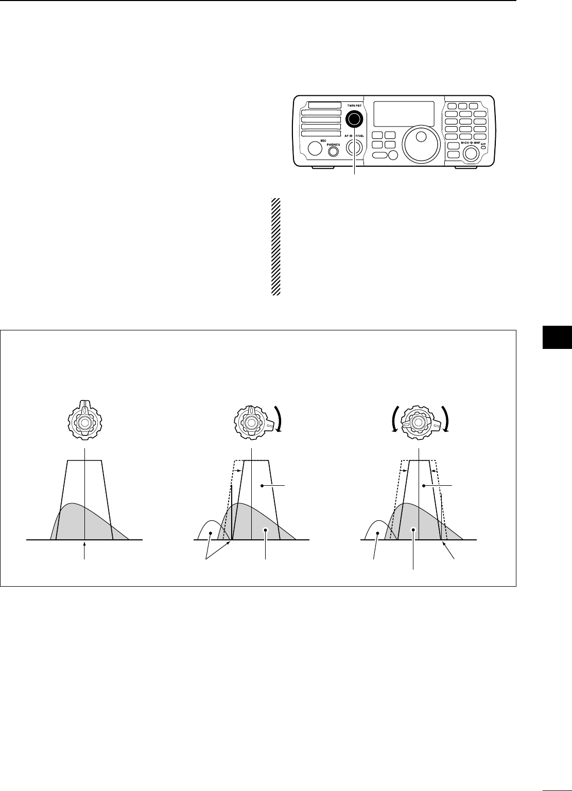
46
5
FUNCTIONS FOR RECEIVE
1
2
3
4
5
6
7
8
9
10
11
12
13
14
15
16
17
18
19
20
21
N Twin PBT operation
The general PBT (Passband Tuning) function elec-
tronically narrows the IF passband width by shifting
the IF frequency slightly outside of the IF filter pass-
band to reject interference. This transceiver uses the
DSP circuit for the PBT function. Moving both controls
to the same position shifts the IF.
The limit of the variable range depends on the pass-
band width and mode. The limit of the variable range
is half of the passband width, and PBT is adjustable
in 25 Hz steps.
MODE
TUNER
TS
FILTER
SPCH
V/M
A/B
SPLIT
M-CL
SCAN
SET
ATT
P
.
AMP
COMP
VOX
MNF
RIT
123
456
78
0
50
28
1814
10
21 24
=
7
3.5
1.8
F-INP
M-CH/RIT
ENT
BAND
GENE
9
.
AGC
MW
ANF
METER
NR
NB
[TWIN PBT]
• The [TWIN PBT] controls should normally be set
to the center positions (PBT setting is cleared)
when there is no interference.
• When PBT is used, the audio tone may be
changed.
• While rotating the [TWIN PBT] control, noise may
occur. This comes from the DSP unit and does
not indicate an equipment malfunction.
PBT OPERATION EXAMPLE
IF center frequency Interference Desired signal
Passband
Both controls at
center position
Cutting the lower
passband
Cutting both higher and
lower passbands
Interference Interference
Desired signal
Passband
TWIN PBTTWIN PBTTWIN PBT
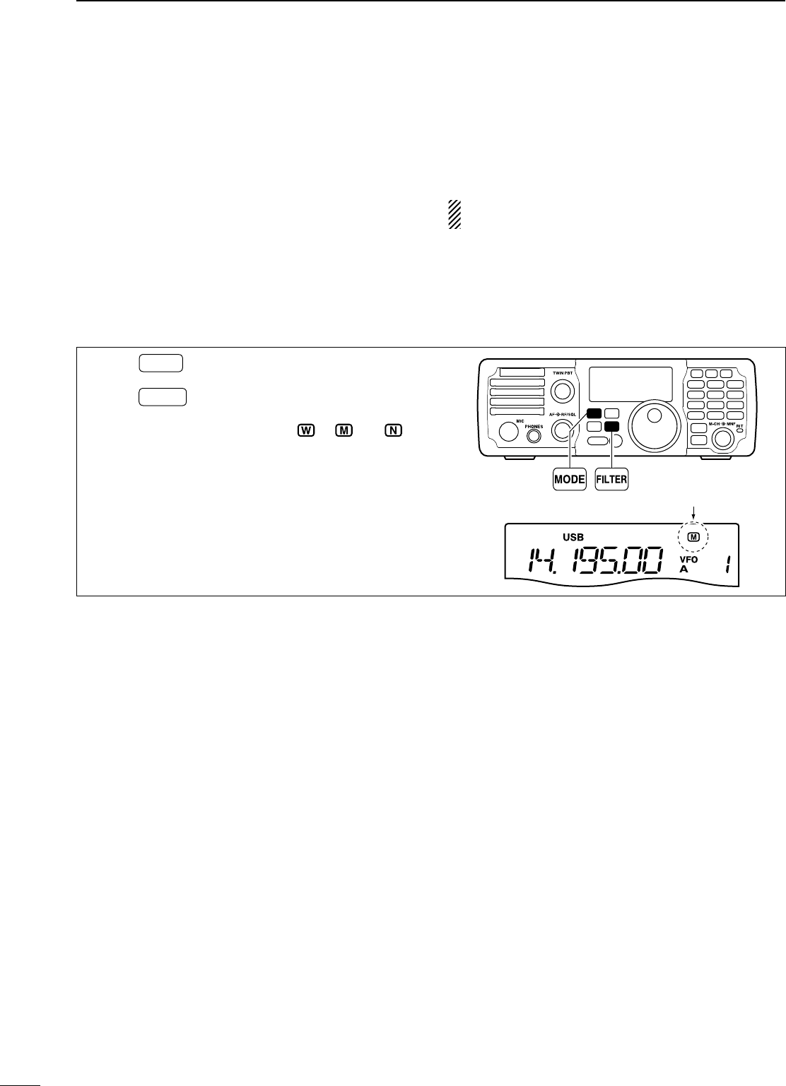
47
5FUNCTIONS FOR RECEIVE
N IF filter selection
The transceiver has 3 passband IF filter widths for
each mode.
For SSB and CW modes, the passband width can be
set from 50 to 3600 Hz in 50 or 100 Hz steps.
A total of 41 passband widths are available.
For RTTY mode, the passband width can be set from
50 to 2700 Hz in 50 or 100 Hz steps.
A total of 32 passband widths are available.
For AM mode, the passband width can be set from
200 to 8000 Hz in 200 Hz steps.
A total of 40 passband widths are available.
The filter selection is automatically memorized in
each mode.
D IF filter selection
q Push MODE several times to select the desired
mode.
w Push FILTER several times to select the IF filter
from Wide, Middle or Narrow.
• The selected IF filter indicator (“ ”, “ ” or “ ”)
appears in the LCD.
MODE
TUNER
TS
FILTER
SPCH
V/M
A/B
SPLIT
M-CL
SCAN
SET
ATT
P
.
AMP
COMP
VOX
MNF
RIT
123
456
78
0
50
28
1814
10
21 24
=
7
3.5
1.8
F-INP
M-CH/RIT
ENT
BAND
GENE
9
.
AGC
MW
ANF
METER
NR
NB
Selected IF filter indicator
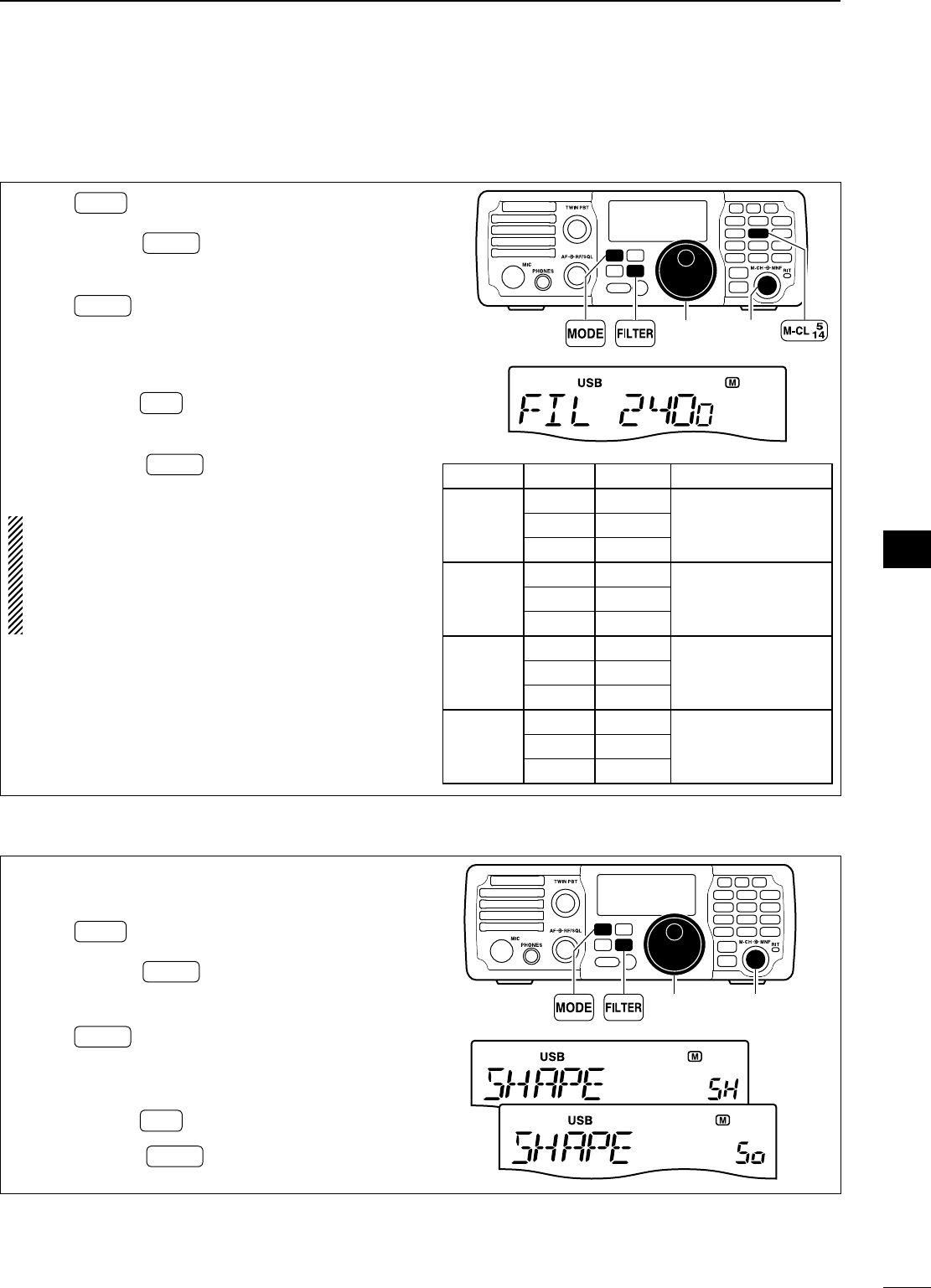
48
5
FUNCTIONS FOR RECEIVE
1
2
3
4
5
6
7
8
9
10
11
12
13
14
15
16
17
18
19
20
21
D FIlter passband width setting
q Push MODE several times to select the desired
mode.
w Push and hold FILTER for 1 sec. to enter filter set
mode.
e Rotate [M-CH] to select “FIL.”
r Push FILTER several times to select the desired
IF filter.
t Rotate [DIAL] to set the desired passband width.
• The passband width can be set within the range as
shown in the table at right below.
• Push and hold M-CL for 1 sec. to return to the default
value.
y Repeat steps r and t if desired.
u Push and hold FILTER for 1 sec. to exit the filter
set mode.
When the IF passband width is set to minimum by
the [TWIN PBT] controls (when one control is
max. counterclockwise, and the other one is max.
clockwise; p. 46), a sound may not come from the
speaker depending on the IF filter passband width
setting. This is not a transceiver’s malfunction.
MODE
TUNER
TS
FILTER
SPCH
V/M
A/B
SPLIT
M-CL
SCAN
SET
ATT
P
.
AMP
COMP
VOX
MNF
RIT
123
456
78
0
50
28
1814
10
21 24
=
7
3.5
1.8
F-INP
M-CH/RIT
ENT
BAND
GENE
9
.
AGC
MW
ANF
METER
NR
NB
[DIAL] [M-CH]
Mode Filter Default Range (Steps)
SSB
Wide 3000 Hz
50–500 Hz (50 Hz)/
600–3600 Hz (100 Hz)
Middle 2400 Hz
Narrow 1800 Hz
SSB Data/
CW
Wide 1200 Hz
50–500 Hz (50 Hz)/
600–3600 Hz (100 Hz)
Middle 500 Hz
Narrow 250 Hz
RTTY
Wide 2400 Hz
50–500 Hz (50 Hz)/
600–2700 Hz (100 Hz)
Middle 500 Hz
Narrow 250 Hz
AM/
AM Data
Wide 8000 Hz
200–8000 Hz (200 Hz)Middle 6000 Hz
Narrow 3000 Hz
D IF fIlter shape (SSB/CW only)
The type of DSP filter shape for SSB and CW can be
selected independently from soft and sharp.
q Push MODE several times to select SSB or CW
mode.
w Push and hold FILTER for 1 sec. to enter filter set
mode.
e Rotate [M-CH] to select “SHAPE.”
r Push FILTER several times to select the desired
IF filter from Wide, Middle or Narrow.
t Rotate [DIAL] to select the desired filter shape,
either soft or sharp
• Push and hold M-CL for 1 sec. to return to the default
value.
y Push and hold FILTER for 1 sec. to exit the filter
set mode.
MODE
TUNER
TS
FILTER
SPCH
V/M
A/B
SPLIT
M-CL
SCAN
SET
ATT
P
.
AMP
COMP
VOX
MNF
RIT
123
456
78
0
50
28
1814
10
21 24
=
7
3.5
1.8
F-INP
M-CH/RIT
ENT
BAND
GENE
9
.
AGC
MW
ANF
METER
NR
NB
[DIAL] [M-CH]
“Sharp”
“Soft”
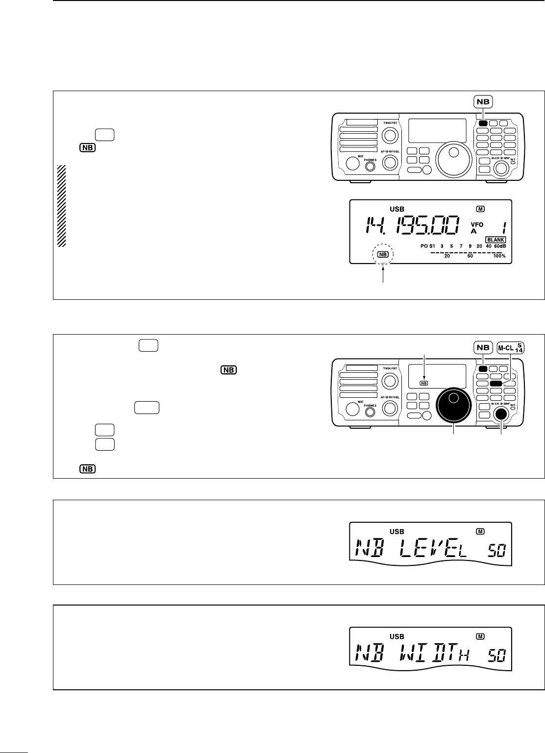
49
5FUNCTIONS FOR RECEIVE
N Noise blanker
The noise blanker eliminates pulse-type noise such
as from car ignition systems.
± Push NB to turn the noise blanker ON or OFF.
• “ ” appears when the NB function is ON.
When using the noise blanker, received signals
may be distorted if they are excessively strong or
the noise type is other than impulse. Nearby
strong signals can also cause the noise blanker to
create distortion. Turn the noise blanker function
OFF, or adjust the noise blanker level to a shal-
lower setting (see below) in this case.
MODE
TUNER
TS
FILTER
SPCH
V/M
A/B
SPLIT
M-CL
SCAN
SET
ATT
P
.
AMP
COMP
VOX
MNF
RIT
123
456
78
0
50
28
1814
10
21 24
=
7
3.5
1.8
F-INP
M-CH/RIT
ENT
BAND
GENE
9
.
AGC
MW
ANF
METER
NR
NB
Appears
D Noise blanker settings
q Push and hold NB for 1 sec. to enter the noise
blanker set mode.
• The noise blanker is turned ON and “ ” appears.
w Rotate [M-CH] to select the desired set item.
e Rotate [DIAL] to adjust the desired condition.
• Push and hold M-CL for 1 sec. to return to the default
value.
r Push NB to exit the noise blanker set mode.
t Push NB to turn the noise blanker OFF if neces-
sary.
• “ ” disappears.
MODE
TUNER
TS
FILTER
SPCH
V/M
A/B
SPLIT
M-CL
SCAN
SET
ATT
P
.
AMP
COMP
VOX
MNF
RIT
123
456
78
0
50
28
1814
10
21 24
=
7
3.5
1.8
F-INP
M-CH/RIT
ENT
BAND
GENE
9
.
AGC
MW
ANF
METER
NR
NB
[DIAL] [M-CH]
Appears
NB LEVEL
This item adjusts the noise blanker level. The noise
blanker attenuation level can be adjusted from 0% to
100%.
50%
(
default
)
NB WIDTH
This item allows adjustment of the blank time for noise
blanker to match the pulse width. The noise blanker width
can be adjusted from 1% to 100%.
50%
(
default
)
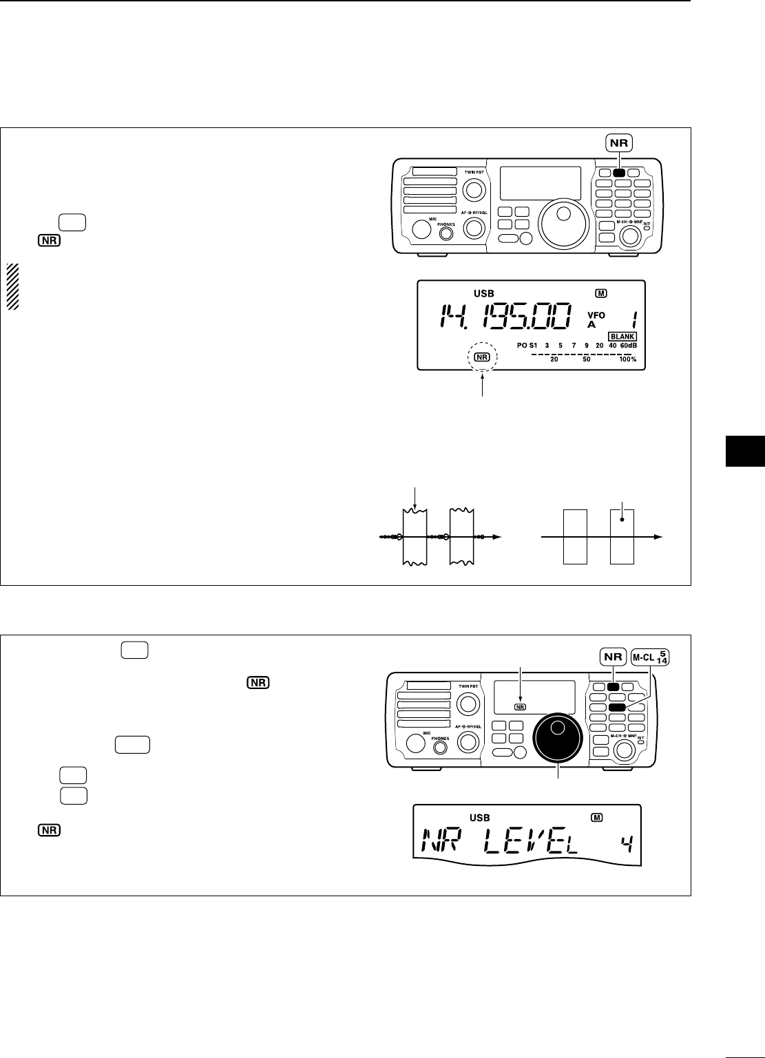
50
5
FUNCTIONS FOR RECEIVE
1
2
3
4
5
6
7
8
9
10
11
12
13
14
15
16
17
18
19
20
21
N Noise reduction
The noise reduction enhances desired signals in
the presence of noise by using the DSP circuit to re-
move random noise. The amount of enhancement is
adjustable.
± Push NR to turn the noise reduction ON or OFF.
• “ ” appears when the NR function is ON.
The noise reduction level can result in audio sig-
nal masking. Set the noise reduction level for
maximum readability as described below.
MODE
TUNER
TS
FILTER
SPCH
V/M
A/B
SPLIT
M-CL
SCAN
SET
ATT
P
.
AMP
COMP
VOX
MNF
RIT
123
456
78
0
50
28
1814
10
21 24
=
7
3.5
1.8
F-INP
M-CH/RIT
ENT
BAND
GENE
9
.
AGC
MW
ANF
METER
NR
NB
Appears
Noise reduction OFF
NR Level 0
Noise reduction is activated
NR Level 4 (default)
Desired
signal (CW)
Noise components
D Noise reduction level setting
q Push and hold NR for 1 sec. to enter the noise
reduction level set mode.
• The noise reduction is turned ON and “ ” appears.
w Rotate [DIAL] to adjust the noise reduction level.
• The noise reduction level can be adjusted from 0 to
15.
• Push and hold M-CL for 1 sec. to return to the default
value.
e Push NR to exit the noise reduction set mode.
r Push NR to turn the noise reduction OFF if nec-
essary.
• “ ” disappears.
MODE
TUNER
TS
FILTER
SPCH
V/M
A/B
SPLIT
M-CL
SCAN
SET
ATT
P
.
AMP
COMP
VOX
MNF
RIT
123
456
78
0
50
28
1814
10
21 24
=
7
3.5
1.8
F-INP
M-CH/RIT
ENT
BAND
GENE
9
.
AGC
MW
ANF
METER
NR
NB
[DIAL]
4 (default)
Appears
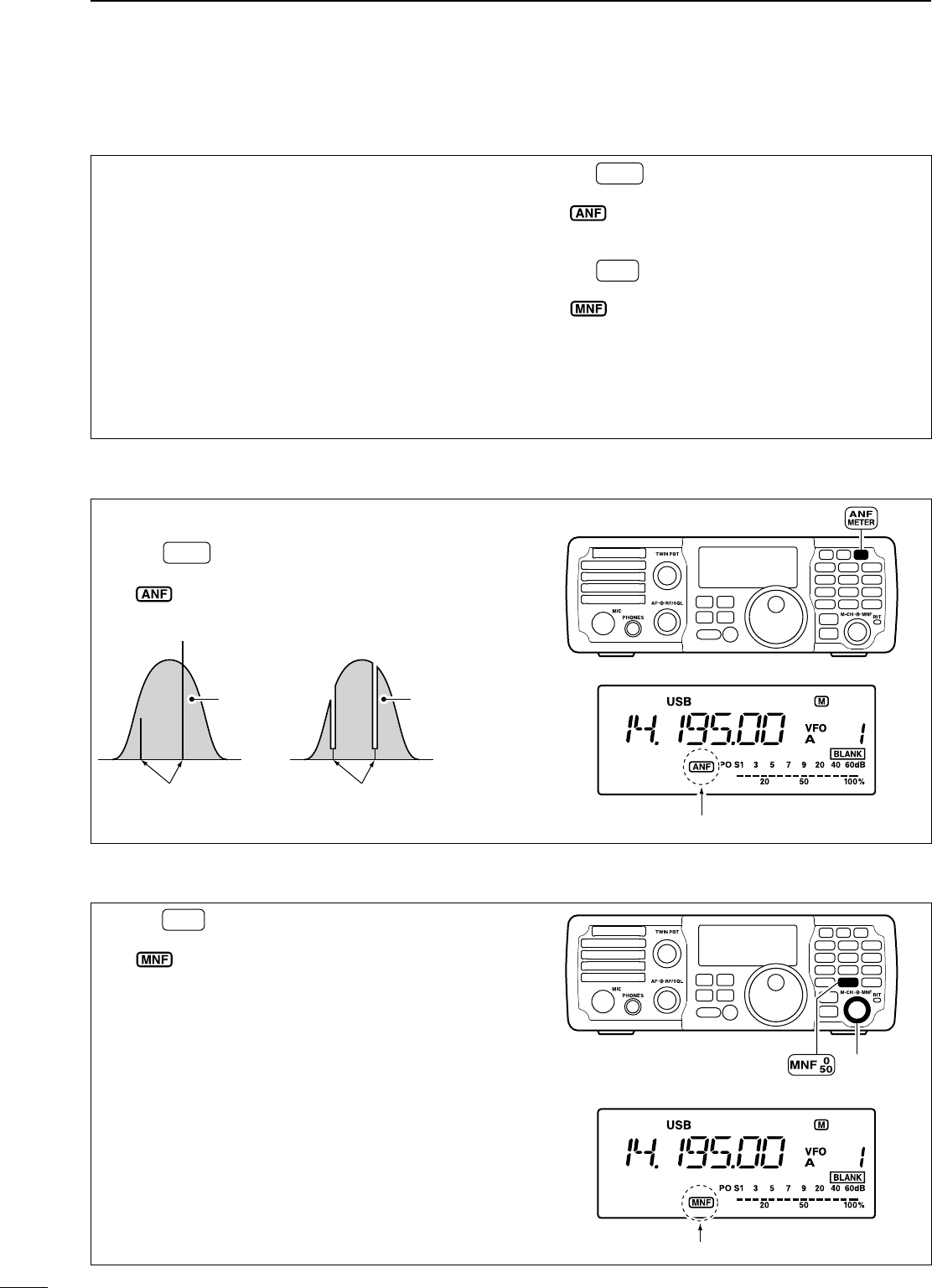
51
5FUNCTIONS FOR RECEIVE
N Notch function
This transceiver has auto and manual notch func-
tions.
The auto notch function automatically attenuates
beat tones, tuning signals, changing frequency, etc.,
even if they are moving.
The manual notch can be set to attenuate a fre-
quency via the [MNF] control.
± Push ANF
METER to turn the auto notch function ON or
OFF.
• “ ” appears when the auto notch function is ON.
• The auto notch function is available while in SSB or
AM mode.
± Push MNF to turn the manual notch function ON
or OFF.
• “” appears when the manual notch function is
ON.
• While in SSB or AM mode, either the auto or manual
notch function can be turned ON. The function that is
turned ON later becomes effective.
• Manual notch filter setting is described on the next
page.
D Auto notch function
The auto notch can be used in SSB and AM modes.
± Push ANF
METER to turn the automatic notch function
ON or OFF.
• “ ” appears when the auto notch function is ON.
Unwanted interference
Desired
signal (AF)
Desired
signal (AF)
Interference frequency
is attenuated
Auto notch OFF Auto notch ON
MODE
TUNER
TS
FILTER
SPCH
V/M
A/B
SPLIT
M-CL
SCAN
SET
ATT
P
.
AMP
COMP
VOX
MNF
RIT
123
456
78
0
50
28
1814
10
21 24
=
7
3.5
1.8
F-INP
M-CH/RIT
ENT
BAND
GENE
9
.
AGC
MW
ANF
METER
NR
NB
Appears
D Manual notch function
± Push MNF to turn the manual notch function ON
or OFF.
• “” appears when the manual notch function is
ON.
• Set to attenuate a frequency for manual notch via the
[MNF] control.
• Set the frequency for manual notch filtering via the
manual notch filter set mode. (described on the next
page)
MODE
TUNER
TS
FILTER
SPCH
V/M
A/B
SPLIT
M-CL
SCAN
SET
ATT
P
.
AMP
COMP
VOX
MNF
RIT
123
456
78
0
50
28
1814
10
21 24
=
7
3.5
1.8
F-INP
M-CH/RIT
ENT
BAND
GENE
9
.
AGC
MW
ANF
METER
NR
NB
Appears
[MNF]
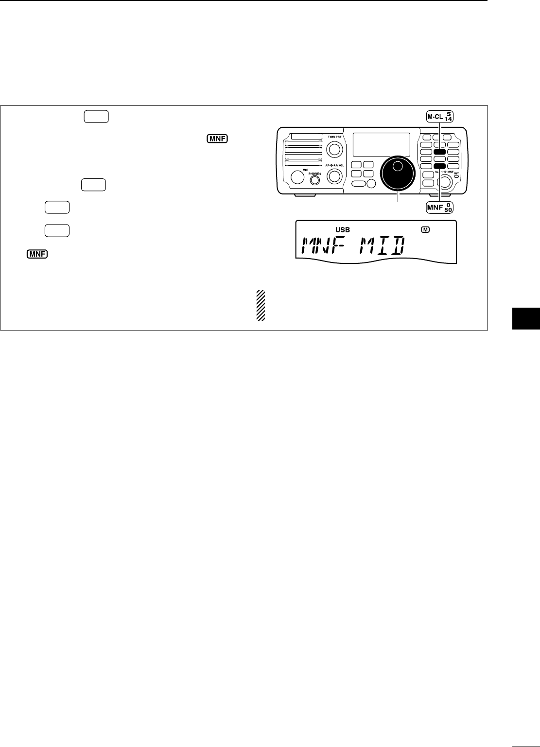
52
5
FUNCTIONS FOR RECEIVE
1
2
3
4
5
6
7
8
9
10
11
12
13
14
15
16
17
18
19
20
21
D Manual notch filter setting
q Push and hold MNF for 1 sec. to enter the man-
ual notch filter set mode.
• The manual notch function is turned ON and “ ”
appears.
w Rotate [DIAL] to select the filter width from nar-
row, middle and wide.
• Push and hold M-CL for 1 sec. to return to the default
value.
e Push MNF to exit the manual notch filter set
mode.
r Push MNF to turn the manual notch function
OFF if necessary.
• “ ” disappears.
MODE
TUNER
TS
FILTER
SPCH
V/M
A/B
SPLIT
M-CL
SCAN
SET
ATT
P
.
AMP
COMP
VOX
MNF
RIT
123
456
78
0
50
28
1814
10
21 24
=
7
3.5
1.8
F-INP
M-CH/RIT
ENT
BAND
GENE
9
.
AGC
MW
ANF
METER
NR
NB
[DIAL]
Middle (default)
While adjusting the manual notch filter, noise may
be heard. This comes from the DSP unit and does
not indicate an equipment malfunction.
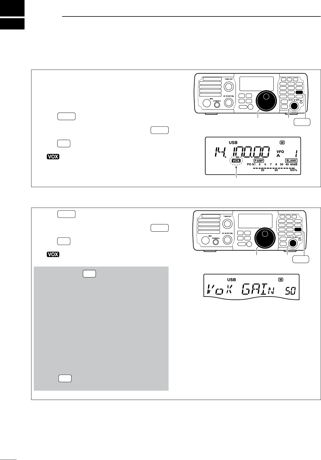
6
53
FUNCTIONS FOR TRANSMIT
N VOX function
The VOX (Voice-Operated Transmission) function
uses your voice to switch between transmit and
receive. This function provides an opportunity for
hands-free operation or to input log entries into your
computer, etc., while operating.
q Push MODE to select a phone mode (SSB or
AM).
• When SSB mode is selected, push and hold MODE
for 1 sec. to toggle between USB and LSB modes.
w Push VOX to toggle the VOX function ON and
OFF.
• “ ” appears when the VOX function is ON.
The VOX gain, ANTI-VOX and VOX delay can be set
in VOX set mode. (See below.)
MODE
TUNER
TS
FILTER
SPCH
V/M
A/B
SPLIT
M-CL
SCAN
SET
ATT
P
.
AMP
COMP
VOX
MNF
RIT
123
456
78
0
50
28
1814
10
21 24
=
7
3.5
1.8
F-INP
M-CH/RIT
ENT
BAND
GENE
9
.
AGC
MW
ANF
METER
NR
NB
[DIAL] [M-CH] VOX
28
9
Appears
D Adjusting the VOX function
q Push MODE to select a phone mode (SSB or
AM).
• When SSB mode is selected, push and hold MODE
for 1 sec. to toggle between USB and LSB modes.
w Push VOX to toggle the VOX function ON and
OFF.
• “ ” appears when the VOX function is ON.
e
Adjust the VOX functions in the VOX set mode.
q Push and hold VOX for 1 sec. to enter the VOX
set mode.
w Rotate [M-CH] to select “VoX GAIN.”
e While speaking into the microphone with your
normal voice level, rotate [DIAL] to the point
where the transceiver is continuously transmit-
ting.
r Rotate [M-CH] to select “ANTI-Vox.”
t During receive, rotate [DIAL] to adjust the anti-
VOX gain to the point where the transceiver
does not switch to transmit due to received
audio from the speaker.
y Rotate [M-CH] to select “VoX DELY.”
u Rotate [DIAL] to adjust the VOX delay for a
convenient interval before returning to receive.
i Push VOX to exit the VOX set mode. and return
to normal operation.
VOX Gain
50% (default)
MODE
TUNER
TS
FILTER
SPCH
V/M
A/B
SPLIT
M-CL
SCAN
SET
ATT
P
.
AMP
COMP
VOX
MNF
RIT
123
456
78
0
50
28
1814
10
21 24
=
7
3.5
1.8
F-INP
M-CH/RIT
ENT
BAND
GENE
9
.
AGC
MW
ANF
METER
NR
NB
[DIAL] [M-CH] VOX
28
9
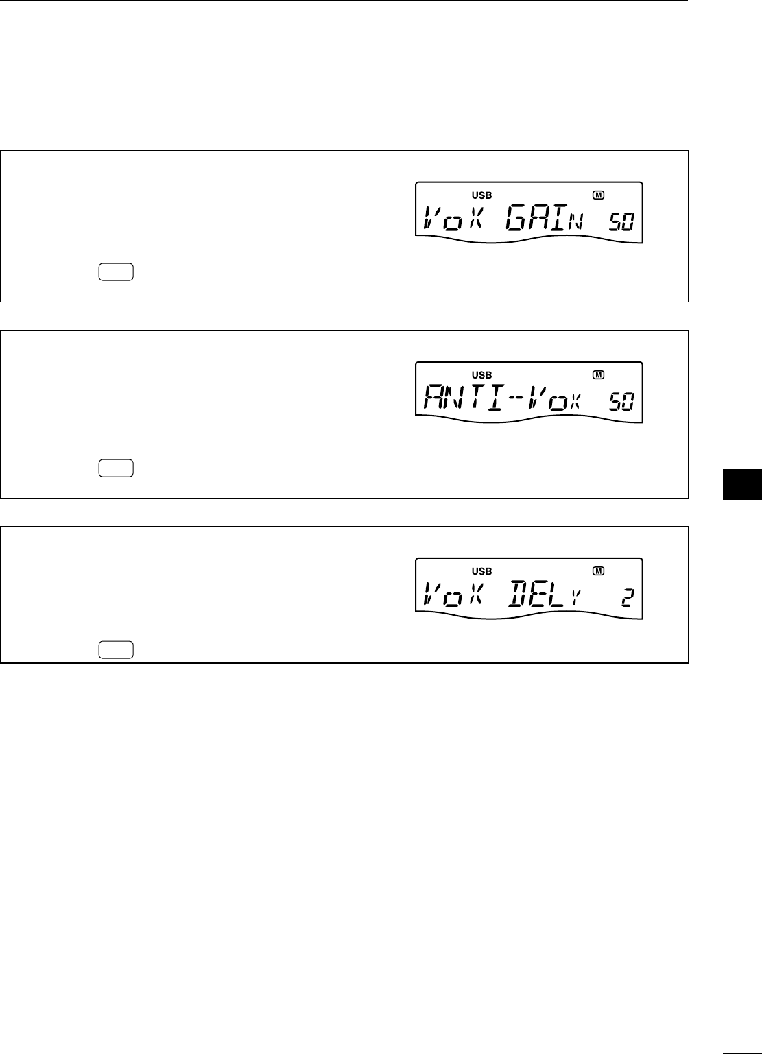
54
6
FUNCTIONS FOR TRANSMIT
1
2
3
4
5
6
7
8
9
10
11
12
13
14
15
16
17
18
19
20
21
D VOX set mode
VOX GAIN
This item adjusts the VOX gain for the VOX (Voice-Oper-
ated Transmission) function. Higher values make the VOX
function more sensitive to your voice.
This setting can be adjusted from 0% to 100% in 1%
steps.
• Push and hold M-CL for 1 sec. to return to the default value.
50%
(
default
)
ANTI-VOX
This item adjusts the ANTI-VOX gain for the VOX (Voice-
Operated Transmission) function.
Higher values make the
VOX function less sensitive to receiver output audio from
a speaker or headphones.
This setting can be adjusted from 0% to 100% in 1%
steps.
• Push and hold M-CL for 1 sec. to return to the default value.
50%
(
default
)
VOX DELAY
This item adjusts the VOX (
Voice-Operated Transmission
)
delay time. VOX Delay is the amount of time the transmit-
ter stays on after you stop speaking.
The delay time can be adjusted from 0 to 2.0 sec. in 0.1
sec. steps.
• Push and hold M-CL for 1 sec. to return to the default value.
0.2 sec.
(
default
)
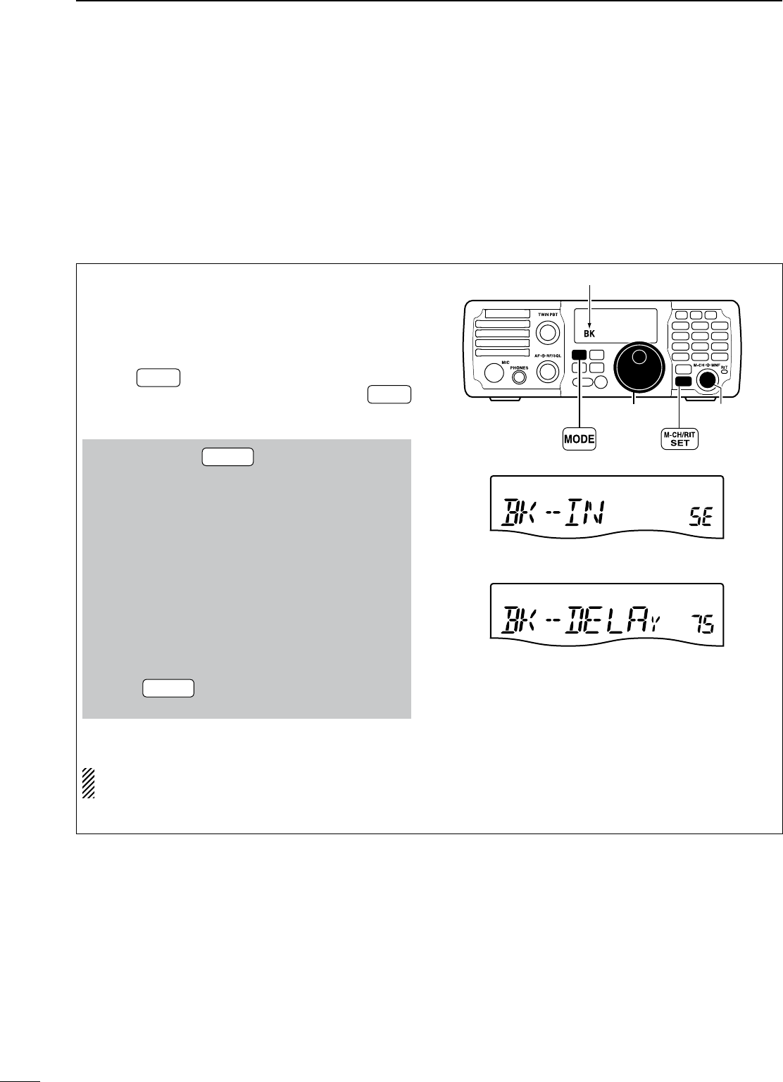
55
6FUNCTIONS FOR TRANSMIT
N Break-in function
The break-in function is used in CW mode to auto-
matically switch the transceiver between transmit and
receive when keying. The IC-7200 is capable of full
break-in or semi break-in. Break-in operation is also
referred to as QSK.
D Semi break-in operation
During semi break-in operation, the transceiver im-
mediately transmits when keying, then automati-
cally returns to receive after a pre-set delay time has
passed from when you stop keying. This is similiar to
VOX operation for voice.
q Push MODE to select CW or CW-R mode.
• When CW mode is selected, push and hold MODE
for 1 sec. to toggle between CW and CW-R modes.
w
Set the semi break-in function ON in the set mode.
q Push and hold M-CH/RIT
SET for 1 sec. twice to enter
the set mode.
w Rotate [M-CH] to select “BK-IN” to set the CW
break-in operation.
e Rotate [DIAL] to select “SE.”
• FL : Full break-in
• SE : Semi break-in
• OF : Break-in OFF
r Rotate [M-CH] to select “BK-DELAY” to select
the CW delay time when semi break-in opera-
tion is selected in step e.
t Rotate [DIAL] to set the desired delay time.
• The delay time is selectable from 0.2 to 13.0 (dots)
in 0.1 (dots) steps.
y Push M-CH/RIT
SET to exit the set mode and return to
normal operation.
e “BK” appears on the LCD.
When using a paddle, set “KEY SPD” in the quick
set mode to adjust the keying speed. (p. 72)
MODE
TUNER
TS
FILTER
SPCH
V/M
A/B
SPLIT
M-CL
SCAN
SET
ATT
P
.
AMP
COMP
VOX
MNF
RIT
123
456
78
0
50
28
1814
10
21 24
=
7
3.5
1.8
F-INP
M-CH/RIT
ENT
BAND
GENE
9
.
AGC
MW
ANF
METER
NR
NB
[DIAL] [M-CH]
Appears
7.5 dots
Semi break-in operation
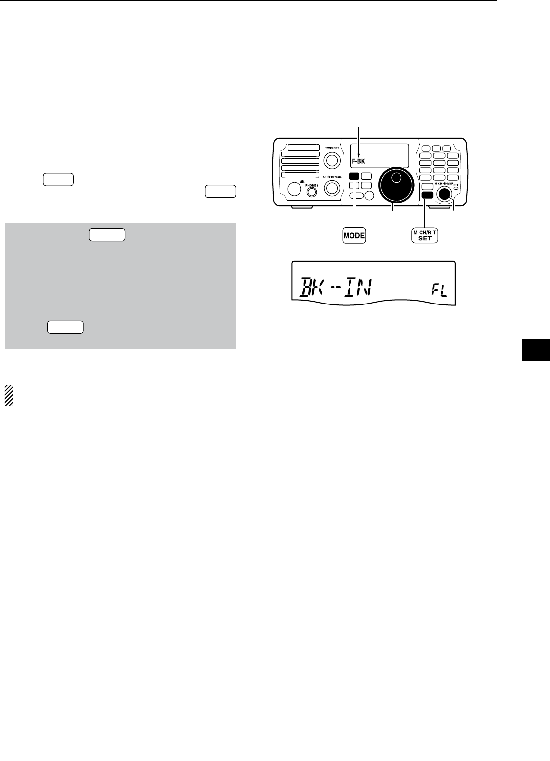
56
6
FUNCTIONS FOR TRANSMIT
1
2
3
4
5
6
7
8
9
10
11
12
13
14
15
16
17
18
19
20
21
D Full break-in operation
During full break-in operation, the transceiver auto-
matically switches to receive between keying dots
and dashes so that the operator can hear activity on
the channel when transmitting.
q Push MODE to select CW or CW-R mode.
• When CW mode is selected, push and hold MODE
for 1 sec. to toggle between CW and CW-R modes.
w
Set the full break-in function ON in the set mode.
q Push and hold M-CH/RIT
SET for 1 sec. twice to enter
the set mode.
w Rotate [M-CH] to select “BK-IN” to set the CW
break-in operation.
e Rotate [DIAL] to select “FL.”
• FL : full break-in
• SE : semi break-in
• OF : break-in OFF
r Push M-CH/RIT
SET to exit the set mode and return to
normal operation.
e “F-BK” appears on the LCD.
When using a paddle, set “KEY SPD” in the quick
set mode to adjust the keying speed. (p. 72)
MODE
TUNER
TS
FILTER
SPCH
V/M
A/B
SPLIT
M-CL
SCAN
SET
ATT
P
.
AMP
COMP
VOX
MNF
RIT
123
456
78
0
50
28
1814
10
21 24
=
7
3.5
1.8
F-INP
M-CH/RIT
ENT
BAND
GENE
9
.
AGC
MW
ANF
METER
NR
NB
[DIAL] [M-CH]
Appears
Full break-in operation
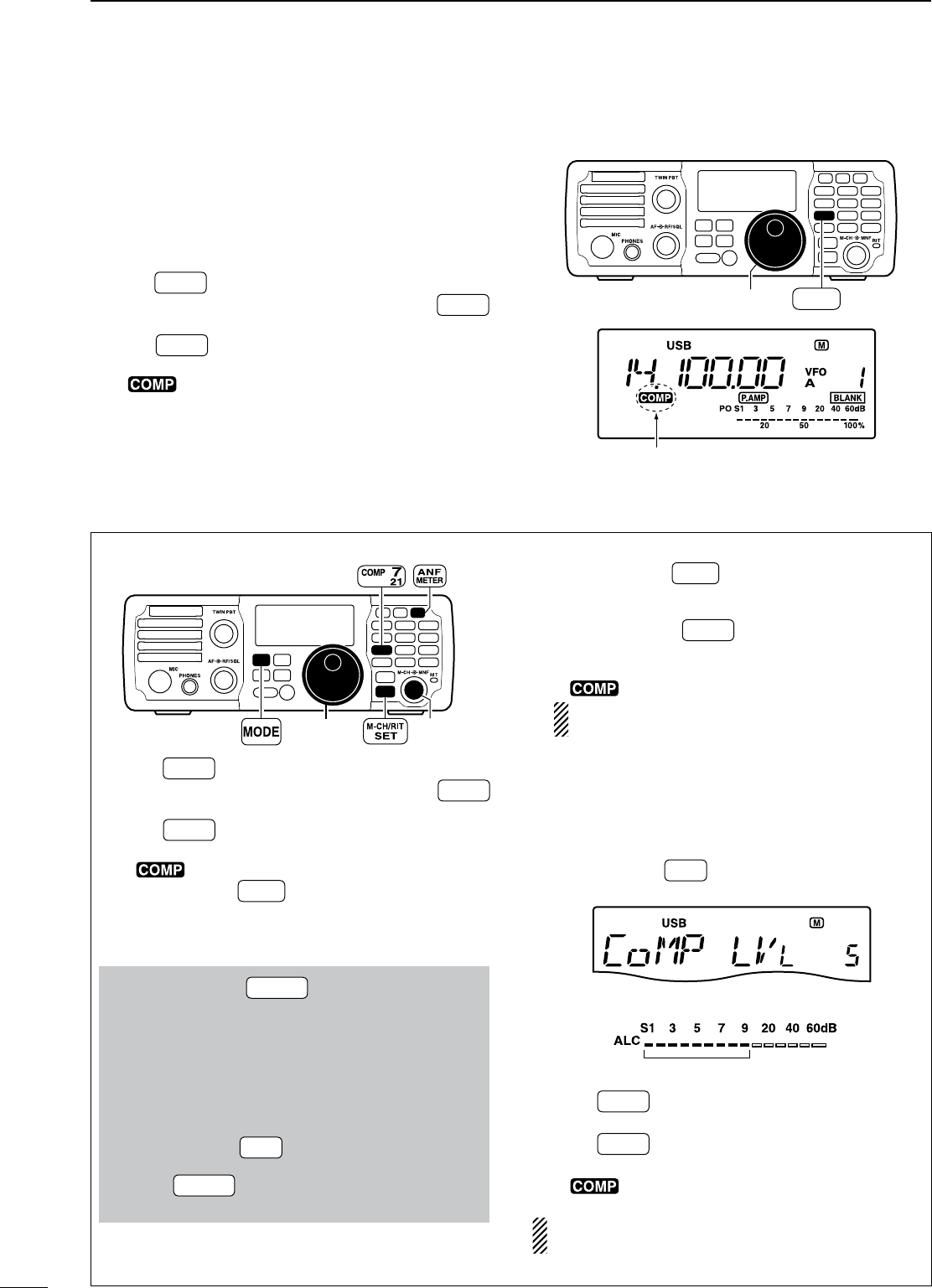
57
6FUNCTIONS FOR TRANSMIT
N Speech compressor
The IC-7200 has a built-in, low distortion speech com-
pressor circuit. This circuit increases your average talk
power in SSB mode and is especially useful for DX-
ing or noisy conditions when the receiving station is
having difficulty copying your signal.
q Push MODE to select an SSB mode.
• When SSB mode is selected, push and hold MODE
for 1 sec. to toggle between USB and LSB modes.
w Push COMP to turn the speech compressor func-
tion ON and OFF.
• “” appears when the speech compressor func-
tion is ON.
MODE
TUNER
TS
FILTER
SPCH
V/M
A/B
SPLIT
M-CL
SCAN
SET
ATT
P
.
AMP
COMP
VOX
MNF
RIT
123
456
78
0
50
28
1814
10
21 24
=
7
3.5
1.8
F-INP
M-CH/RIT
ENT
BAND
GENE
9
.
AGC
MW
ANF
METER
NR
NB
[DIAL]
Appears
COMP
7
21
D Compression level setting
• Microphone gain setting
MODE
TUNER
TS
FILTER
SPCH
V/M
A/B
SPLIT
M-CL
SCAN
SET
ATT
P
.
AMP
COMP
VOX
MNF
RIT
123
456
78
0
50
28
1814
10
21 24
=
7
3.5
1.8
F-INP
M-CH/RIT
ENT
BAND
GENE
9
.
AGC
MW
ANF
METER
NR
NB
[DIAL] [M-CH]
q Push MODE to select an SSB mode.
• When SSB mode is selected, push and hold MODE
for 1 sec. to toggle between USB and LSB modes.
w Push COMP to turn the speech compressor func-
tion OFF, if it’s ON.
• “ ” disappears.
e Push and hold ANF
METER for 1 sec. several times to
select ALC meter.
• “ALC” appears.
r Adjust the MIC gain
in the quick set mode.
q Push and hold M-CH/RIT
SET for 1 sec. to enter the
quick set mode.
w Rotate [M-CH] to select “MIC GAIN” to set the
microphone gain.
e
While transmitting, speak at a normal voice level
and rotate [DIAL] to adjust the microphone gain
so that the ALC meter reads within the ALC
zone, whether you speak softly or loudly.
• Push and hold M-CL for 1 sec. to return to the de-
fault value.
r Push M-CH/RIT
SET to exit the quick set mode and
return to normal operation.
• Compression level setting
q Push and hold ANF
METER for 1 sec. several times to
select ALC meter.
• “ALC” appears.
w Push and hold COMP for 1 sec. to enter the
speech compression level set mode.
• The speech compressor function is turned ON and
“” appears.
You can enter the speech compression level set
mode before selecting ALC meter in step q.
e While transmitting, speak at a normal voice level
and rotate [DIAL] to adjust the speech compres-
sion level so that the ALC meter reads within the
ALC zone, whether you speak softly or loudly.
• The speech compression level can be adjusted from 0
to 10.
• Push and hold M-CL for 1 sec. to return to the default
value.
Level 5 (default)
ALC zone
r
Push
COMP
to exit the speech compression level
set mode and return to normal operation.
t Push COMP to turn the speech compressor func-
tion OFF if necessary.
• “ ” disappears.
NOTE: When the ALC meter peaks above the ALC
zone, your transmitted voice may be distorted.
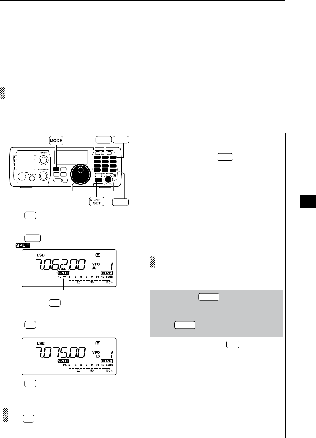
58
6
FUNCTIONS FOR TRANSMIT
1
2
3
4
5
6
7
8
9
10
11
12
13
14
15
16
17
18
19
20
21
N Split frequency operation
Split frequency operation allows you to transmit and
receive in the same mode on two different frequen-
cies. The split frequency operation is performed using
2 frequencies in VFO A and VFO B.
The transmit and receive frequencies must be in
the same band
The following is an example of setting 7.0620 MHz for
receiving and 7.0750 MHz for transmitting.
MODE
TUNER
TS
FILTER
SPCH
V/M
A/B
SPLIT
M-CL
SCAN
SET
ATT
P
.
AMP
COMP
VOX
MNF
RIT
123
456
78
0
50
28
1814
10
21 24
=
7
3.5
1.8
F-INP
M-CH/RIT
ENT
BAND
GENE
9
.
AGC
MW
ANF
METER
NR
NB
[DIAL] [M-CH]
F-INP ENT
BAND
A/B
2
=
3.5
SPLIT
3
7
Keypad
q Push A/B
=
to select VFO A.
w Set the frequency to 7.0620 MHz and mode to
LSB. (pgs. 25, 29)
e Push SPLIT to turn the split function ON.
• “ ” appears on the LCD.
Appears
r Push and hold A/B
=
for 1 sec. to
equalize the un-
displayed VFO B frequency and operating mode
with the displayed VFO A.
t Push A/B
=
to select
the VFO B.
y Set the frequency to 7.0750 MHz (LSB). (p. 25)
u Push A/B
=
to return to
the VFO A.
i Now you can receive on 7.0620 MHz and transmit
on 7.0750 MHz.
To swap the transmit and receive frequencies,
push A/B
=
to exchange the VFO A and VFO B.
CONVENIENT!
M QUICK SPLIT FUNCTION (p. 59)
When you push and hold SPLIT for 1 sec., the split
function is activated, and the undisplayed VFO is set
the same as the displayed VFO. (This operation is
same as the steps e and r as at left.)
This shortens the time needed to start split fre-
quency operation.
Quick split function is turned ON by default but can
be turned OFF in the set mode (p. 76).
M XFC FUNCTION (p. 76)
When the XFC (transmit frequency check) function
is ON, the transmit frequency can be changed (this
operation is same as the steps t and y as at left.)
NOTE: When the XFC function is ON, the RIT cal-
culation function (p. 44) is not available.
q Set the XFC (transmit frequency check) function
ON in the set mode.
q Push and hold M-CH/RIT
SET for 1 sec. twice to enter
the set mode.
w Rotate [M-CH] to select “XFC.”
e Rotate [DIAL] to select ON.
r Push M-CH/RIT
SET to exit the set mode and return to
normal operation.
w While pushing and holding RIT , the transmit fre-
quency is indicated. And rotate [DIAL] to set the
transmit frequency.
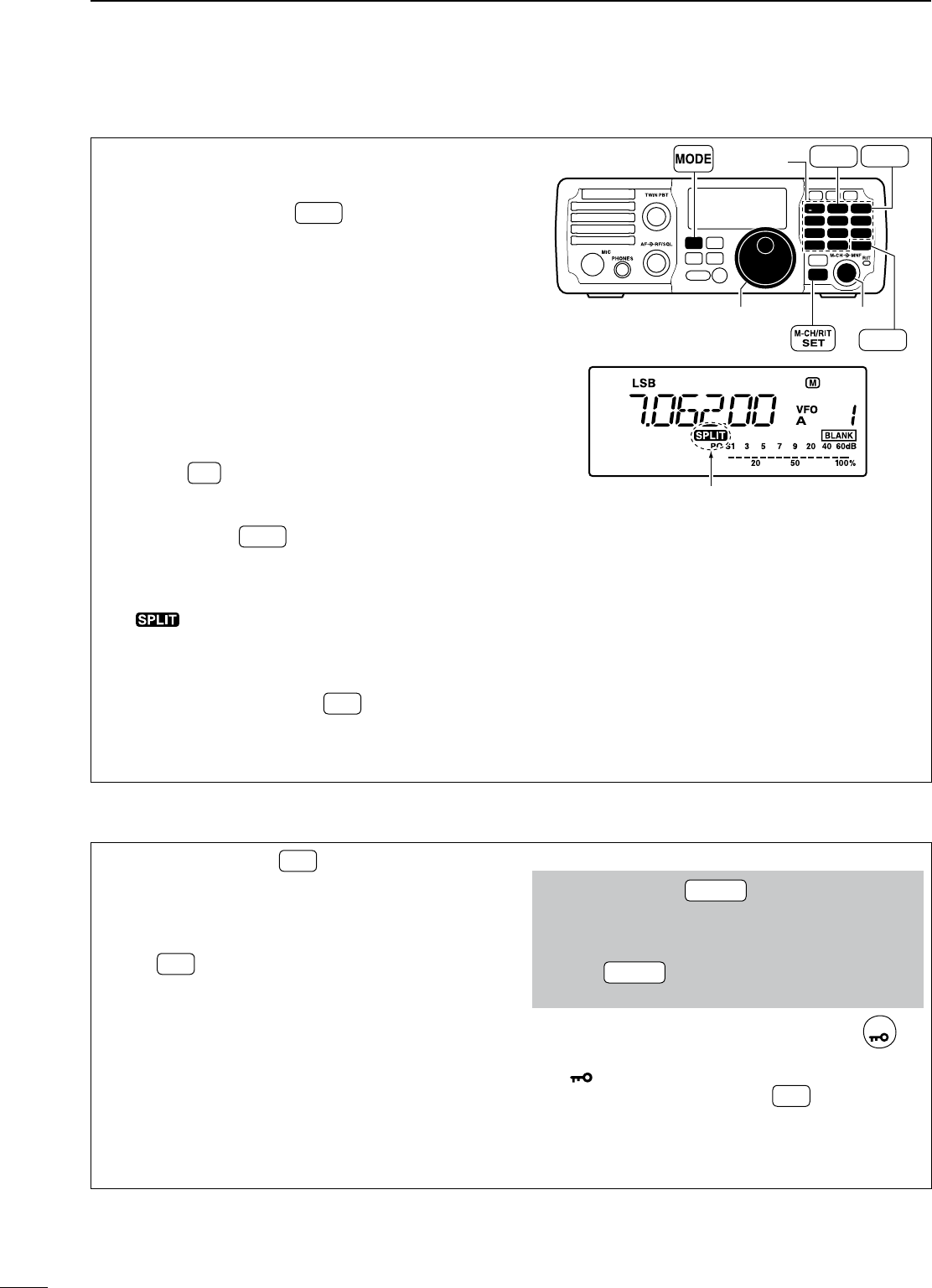
59
6FUNCTIONS FOR TRANSMIT
D Quick split function
When you find a DX station, an important considera-
tion is how to set the split frequency.
When you push and hold SPLIT for 1 sec., the split
function is activated, and the undisplayed VFO is set
the same as the displayed VFO.
This shortens the time needed to start split fre-
quency operation.
Quick split operation is turned ON by default but can
be turned OFF in the set mode (p. 76).
The following is an example of setting 7.0620 MHz
for receiving and 7.0750 MHz for transmitting.
q Select VFO A.
• Pushing A/B
=
toggles VFO A and VFO B.
w Set the frequency to 7.0620 MHz and mode to
LSB. (pgs. 25, 29)
e Push and hold SPLIT for 1 sec. to turn the split
function ON and equalize the undisplayed VFO B
frequency and operating mode with the displayed
VFO A.
• “ ” appears on the LCD.
r Set the XFC (transmit frequency check) function
ON in the set mode. (pgs. 58, 76)
• The default setting is OFF.
t While pushing and holding RIT , rotate [DIAL] to
set the transmit frequency to 7.0750 MHz.
y Now you can receive on 7.0620 MHz and transmit
on 7.0750 MHz.
MODE
TUNER
TS
FILTER
SPCH
V/M
A/B
SPLIT
M-CL
SCAN
SET
ATT
P
.
AMP
COMP
VOX
MNF
RIT
123
456
78
0
50
28
1814
10
21 24
=
7
3.5
1.8
F-INP
M-CH/RIT
ENT
BAND
GENE
9
.
AGC
MW
ANF
METER
NR
NB
[DIAL] [M-CH]
F-INP ENT
BAND
A/B
2
=
3.5
SPLIT
3
7
Keypad
Appears
D Split lock function
Accidentally releasing RIT while rotating [DIAL]
changes the receive frequency. To prevent this, use
both the split lock and dial lock functions to change
the transmit frequency only. The split lock func-
tion cancels the dial lock function while pushing and
holding RIT during split frequency operation.
The dial lock’s effectiveness during split frequency
operation can be selected in the set mode for both
receive and transmit frequencies; or only the receive
frequency. (p. 76)
When the split lock function is ON, the transmit fre-
quency cannot be adjusted by rotating [DIAL] while
pushing and holding [PTT] even if the lock function
is not activated.
q Set the split lock function ON in the set mode.
q Push and hold M-CH/RIT
SET for 1 sec. 2 times to
enter the set mode.
w Rotate [M-CH] to select “SPLIT LK.”
e Rotate [DIAL] to select ON.
r Push M-CH/RIT
SET to exit the set mode and return to
normal operation.
w During split operation, push and hold
SPCH
for
1 sec. to turn the dial lock function ON.
• “ ” appears on the LCD.
e While pushing and holding RIT *, the transmit
frequency and mode are indicated. And Rotate
[DIAL] to set the transmit frequency.
*XFC function is should be turned ON in advance. (p. 76)
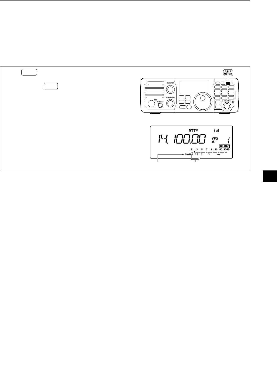
60
6
FUNCTIONS FOR TRANSMIT
1
2
3
4
5
6
7
8
9
10
11
12
13
14
15
16
17
18
19
20
21
NMeasuring SWR
The IC-7200 has a built-in circuit for measuring an-
tenna SWR—no external equipment is necessary.
q Push MODE to select CW or RTTY mode.
w Confirm that the output power is over 30 W.
e Push and hold ANF
METER for 1 sec. several times to
select the SWR meter.
r Push [PTT] to transmit; then read the actual SWR
from the meter.
• ≤ 1.5 well-matched antenna
• > 1.5 may indicate an antenna out of its well-matched
frequency range. If much larger than 2.0, check an-
tenna and cable connections, etc.
MODE
TUNER
TS
FILTER
SPCH
V/M
A/B
SPLIT
M-CL
SCAN
SET
ATT
P
.
AMP
COMP
VOX
MNF
RIT
123
456
78
0
50
28
1814
10
21 24
=
7
3.5
1.8
F-INP
M-CH/RIT
ENT
BAND
GENE
9
.
AGC
MW
ANF
METER
NR
NB
Appears The best match is in this range.
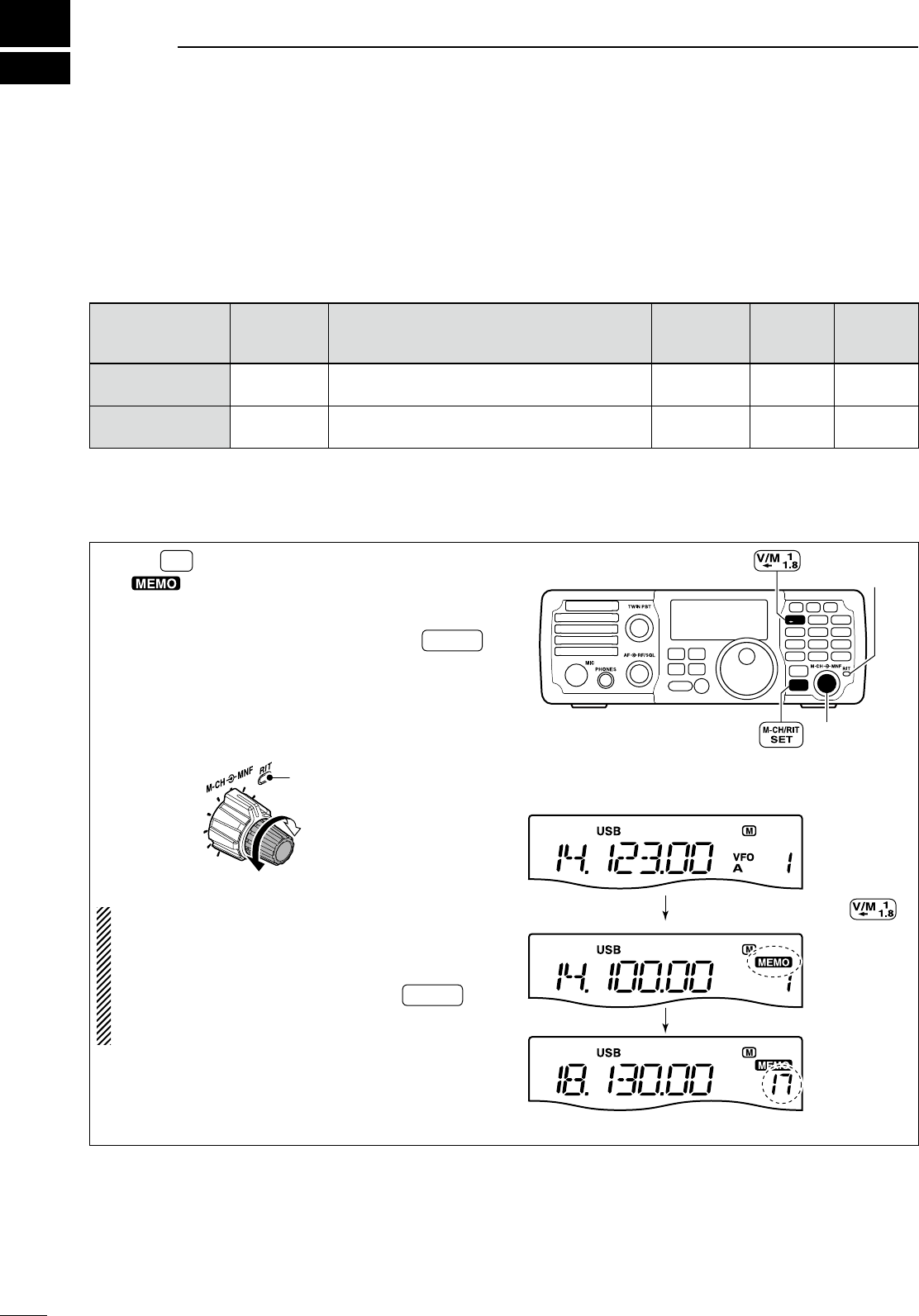
7
61
MEMORY OPERATION
NMemory channels
The transceiver has 201 memory channels including
2 scan edge channels.
Memory mode is very useful for quickly changing to
often-used frequencies.
All 201 memory channels are tuneable which means
the programmed frequency can be tuned temporarily
with [DIAL], etc., in memory mode.
MEMORY
CHANNEL
MEMORY
CHANNEL
NUMBER
CAPABILITY COPY
TO VFO
OVER-
WRITING CLEAR
Regular memory
channels1–199 Independent transmit and receive frequencies
and mode in each memory channel. Ye s Ye s Ye s
Scan edge
memory channelsP1, P2 One frequency and one mode in each memory
channel as scan edges for programmed scan. Yes Yes No
NMemory channel selection
q Push V/M
to select memory mode.
• “ ” appears.
w Rotate [M-CH] to select the desired memory
channel.
• If the RIT control indicator lights red, push M-CH/RIT
SET
to turn the RIT function OFF. (See below for details)
• All memory channels including blank channels can be
selected.
•
[UP]/[DN] on the microphone also selects the mem-
ory channels. (The only programmed memory chan-
nels are selectable.)
Channel decreases
Channel increases
RIT control indicator
goes out
About the [M-CH] control:
When the RIT control indicator lights red, the
memory channels cannot be selected with rotat-
ing the [M-CH] control because the [M-CH] con-
trol acts as the RIT control. So, push M-CH/RIT
SET to
set the [M-CH] control to memory channel control
(RIT control indicator goes out).
MODE
TUNER
TS
FILTER
SPCH
V/M
A/B
SPLIT
M-CL
SCAN
SET
ATT
P
.
AMP
COMP
VOX
MNF
RIT
123
456
78
0
50
28
1814
10
21 24
=
7
3.5
1.8
F-INP
M-CH/RIT
ENT
BAND
GENE
9
.
AGC
MW
ANF
METER
NR
NB
[M-CH]
RIT control
indicator
[EXAMPLE]: Selecting memory channel 17.
Push
Appears
Rotate [M-CH]
VFO mode
Memory mode
Channel 17 is selected.
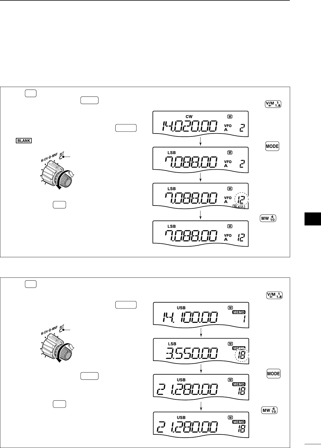
62
7
MEMORY OPERATION
1
2
3
4
5
6
7
8
9
10
11
12
13
14
15
16
17
18
19
20
21
NMemory programming
Memory channel programming can be performed
either in VFO mode or in memory mode.
D Programming in VFO mode
q Push V/M
to select VFO mode.
w Rotate [DIAL], and push MODE to set the de-
sired frequency and operating mode.
e Rotate [M-CH] to select the desired memory
channel.
• If the RIT control indicator lights red, push M-CH/RIT
SET .
(p. 61)
• “ ” appears if the selected memory channel is a
blank channel (one without any stored frequencies).
Channel decreases
Channel increases
RIT control indicator
goes out
r Push and hold MW for 1 sec. to program the
displayed frequency and operating mode into the
selected memory channel.
• 3 beeps are emitted when memory programming is
successful.
[EXAMPLE]: Programming 7.088 MHz/LSB
into ch 12. Push
VFO mode
Rotate [DIAL]
Push
Rotate [M-CH]
Push and hold
7.088 MHz/LSB are programmed into ch 12.
D Programming in memory mode
q Push V/M
to select memory mode.
w Rotate [M-CH] to select the desired memory
channel.
• If the RIT control indicator lights red, push M-CH/RIT
SET .
(p. 61)
•
Memory channel contents appear in the display.
Channel decreases
Channel increases
RIT control indicator
goes out
e Rotate [DIAL], and push MODE to set the de-
sired frequency and operating mode.
• To program a blank channel, use direct frequency
entry with the keypad. (p. 25)
r Push and hold MW for 1 sec. to program the
displayed frequency and operating mode into the
memory channel.
• 3 beeps are emitted when memory programming is
successful.
[EXAMPLE]: Programming 21.280 MHz/USB
into ch 18.
Push
Memory mode
Rotate [DIAL]
Push
Rotate [M-CH]
Push and hold
21.280 MHz/USB are programmed into ch 18.
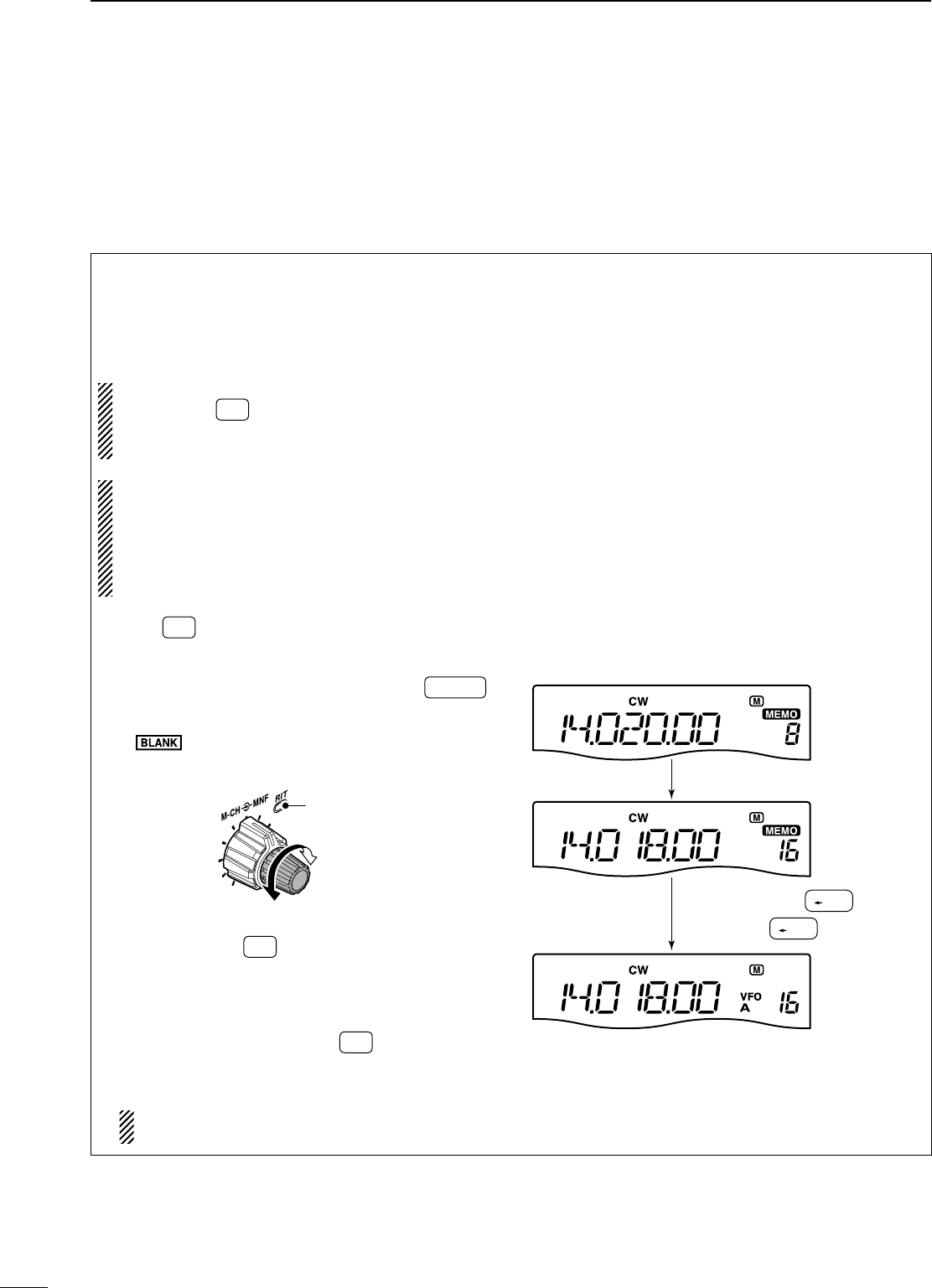
63
NFrequency copying
The frequency and operating mode in a memory
channel can be copied to the VFO.
D Copying in memory mode
This is useful for copying a memory channel’s con-
tents (frequency and operating mode) to a VFO while
operating in memory mode.
This is useful when searching for signals around a
memory channel frequency.
NOTE: While operating in VFO mode, pushing
and holding V/M
for 1 sec. also copy a memory
channel’s contents (frequency and operating
mode) to a VFO.
When you have changed the frequency or operat-
ing mode in the selected memory channel:
• Displayed frequency and mode are copied.
• Programmed frequency and mode in the mem-
ory channel are not copied, and they remain in
the memory channel.
q Push V/M
to select memory mode.
w Rotate [M-CH] to select the desired memory
channel to be copied.
• If the RIT control indicator lights red, push M-CH/RIT
SET .
(p. 61)
• Set the frequency or operating mode if required.
• “” appears if the selected memory channel is a
blank channel (and does not have contents). In this
case copying is not possible.
Channel decreases
Channel increases
RIT control indicator
goes out
e Push and hold V/M
for 1 sec. to copy the fre-
quency and operating mode into the VFO A.
• 3 beeps are emitted when the copying is successful.
• Displayed frequency and operating mode are copied
to the VFO A.
r To return to VFO mode, push V/M
.
• Copied frequency and operating mode appear in the
display.
You can return to VFO mode before copying
the frequency and operating mode in step e.
[EXAMPLE]: Copying contents of memory 16.
Operating frequency
Contents of memory 16
: 14.020 MHz/CW
: 14.018 MHz/CW
V/M
1
1.8
Push and hold for 1 sec.,
then push .
V/M
1
1.8
Rotate [M-CH]
7MEMORY OPERATION
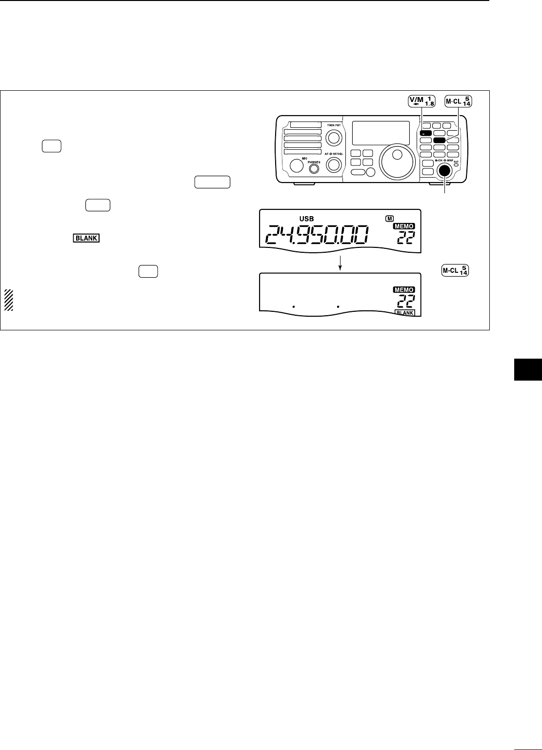
64
7
MEMORY OPERATION
1
2
3
4
5
6
7
8
9
10
11
12
13
14
15
16
17
18
19
20
21
NMemory clearing
Any unnecessary memory channels can be cleared.
The cleared memory channels become blank chan-
nels.
q Push V/M
to select memory mode.
w Rotate [M-CH] to select the desired memory
channel to be cleared.
• If the RIT control indicator lights red, push M-CH/RIT
SET .
(p. 61)
e Push and hold M-CL for 1 sec. to clear the con-
tents.
• The programmed frequency and operating mode dis-
appear and “ ” appears.
• 3 beeps are emitted when memory clearing is suc-
cessful.
r
To return to VFO mode, push
V/M
.
NOTE: Be careful!— the contents of cleared memo-
ries CANNOT be recalled.
MODE
TUNER
TS
FILTER
SPCH
V/M
A/B
SPLIT
M-CL
SCAN
SET
ATT
P
.
AMP
COMP
VOX
MNF
RIT
123
456
78
0
50
28
1814
10
21 24
=
7
3.5
1.8
F-INP
M-CH/RIT
ENT
BAND
GENE
9
.
AGC
MW
ANF
METER
NR
NB
[M-CH]
Push and hold
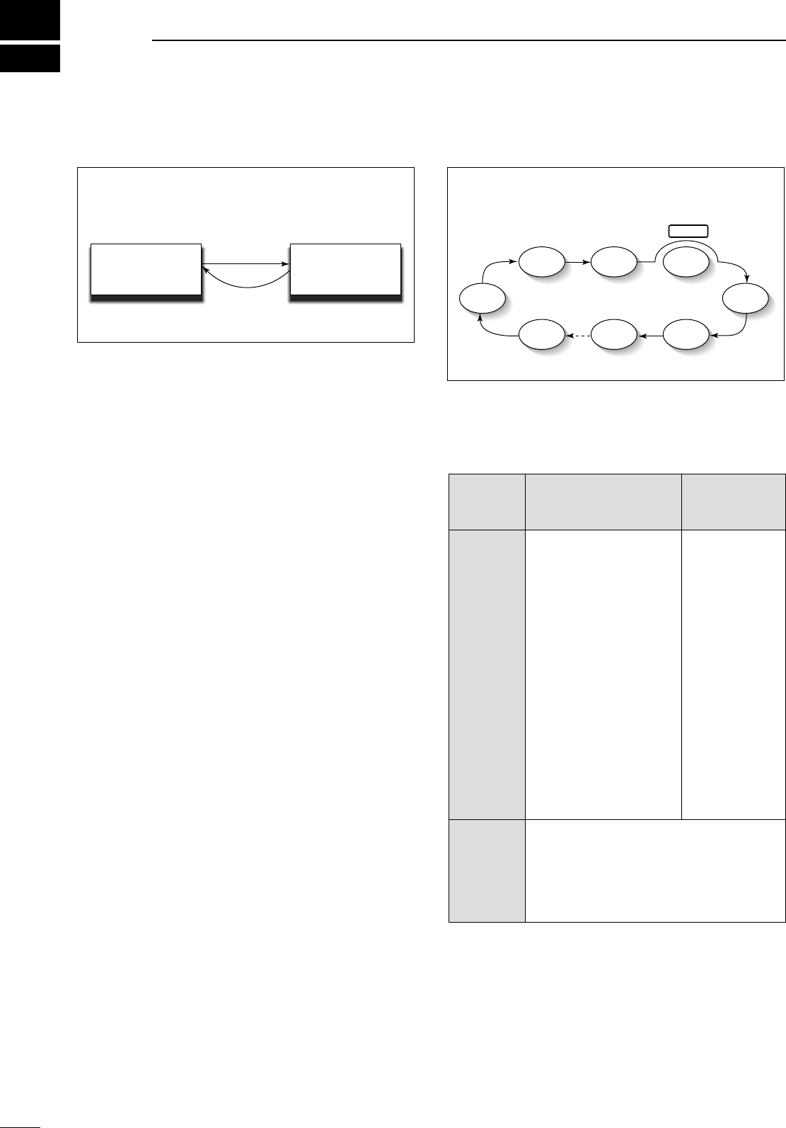
8
65
SCAN OPERATION
• Channels
For programmed scan:
Program scan edge frequencies into scan edge mem-
ory channels P1 and P2. (p. 66)
For memory scan:
Program two or more memory channels except scan
edge memory channels.
• Scan resume ON/OFF
You can select the scan to resume or cancel when
detecting a signal in the set mode.
Scan resume ON/OFF must be set before operating a
scan. See p. 78 for ON/OFF setting and scan resume
condition details.
• Scan speed
Scan speed can be selected from 2 levels, high or
low, in the set mode. See p. 78 for details.
• Squelch condition
SCAN
STARTS
WITH
PROGRAMMED
SCAN
MEMORY
SCAN
SQUELCH
OPEN
TS: 0.1/1 kHz
The scan continues un-
til it is stopped manu-
ally (pushing [SCAN] or
closing the squelch), and
does not pause even
if signals are detected
when the scan resume is
ON.
The scan pauses for 10
sec. when the squelch is
closed, then resumes.
TS: 5/9/10 kHz
Scan pauses on each
step when the scan
resume is ON; not appli-
cable when OFF.
Scan pauses on
each channel
when the scan
resume is ON;
not applicable
when OFF.
SQUELCH
CLOSED
Scan stops when a signal is detected.
If you set scan resume ON in the set mode,
the scan pauses for 10 sec. when detect-
ing a signal, then resumes. When a signal
disappears while scan is paused, scan
resumes 2 sec. later.
N Scan types
N Preparation
PROGRAMMED SCAN
Repeatedly scans between two scan edge frequencies
(scan edge memory channels P1 and P2).
This scan operates in VFO mode.
Scan
Scan edge P1 or P2 Scan edge P2 or P1
Jump
This scan operates in memory mode.
MEMORY SCAN
Repeatedly all programmed memory channels that
are not blank.
Mch 1 Mch 5
Mch 2 Mch 3 Mch 4
Mch 6Mch 7Mch 199
BLANK
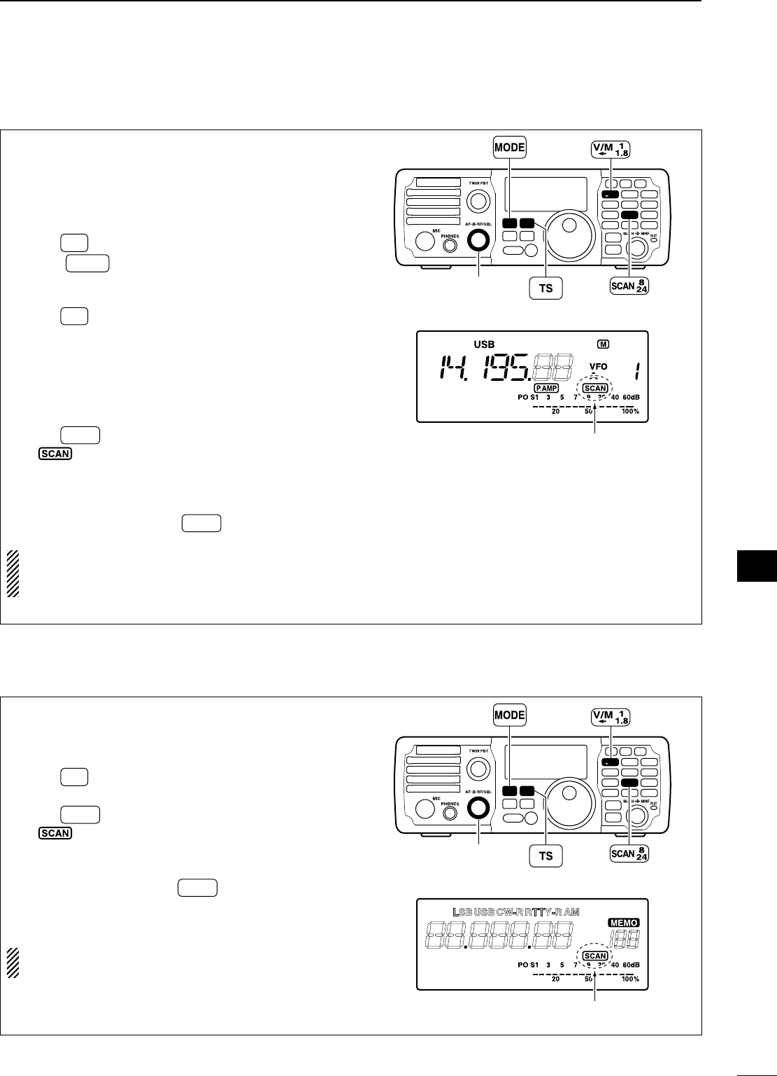
66
8
SCAN OPERATION
1
2
3
4
5
6
7
8
9
10
11
12
13
14
15
16
17
18
19
20
21
N Programmed scan operation (VFO mode)
Programmed scan searches for signals between
scan edge memory channels P1 and P2.
The default frequencies for these memories are
0.500000 MHz and 29.99999 MHz, respectively.
See p. 62 for scan edges programming.
q Push V/M
to select VFO mode.
w Push MODE to select the desired operating
mode.
• The operating mode can be changed while scanning.
e Push TS to select a tuning step.
• The tuning step can be changed while scanning.
r Set the [RF/SQL] control open or closed.
• See the left page for squelch condition.
• If the [RF/SQL] control function is set as “AUTO,”
the squelch is always open in SSB, CW and RTTY
modes. See pgs. 4, 30, 75 for details.
t Push SCAN to start the scan.
• “ ” appears while scanning.
y When the scan detects a signal, the scan turns
OFF, pauses or ignores it depending on the
resume setting and the squelch condition.
u To cancel the scan, push SCAN .
NOTE:
If the same frequencies are programmed
into both scan edge memory channels P1 and P2,
programmed scan does not start.
MODE
TUNER
TS
FILTER
SPCH
V/M
A/B
SPLIT
M-CL
SCAN
SET
ATT
P
.
AMP
COMP
VOX
MNF
RIT
123
456
78
0
50
28
1814
10
21 24
=
7
3.5
1.8
F-INP
M-CH/RIT
ENT
BAND
GENE
9
.
AGC
MW
ANF
METER
NR
NB
[RF/SQL]
Appears
N Memory scan operation (Memory mode)
Memory scan searches through memory channel
1 to 199 for signals. Blank (unprogrammed) memory
channels are skipped.
q Push V/M
to select memory mode.
w Close the squelch with the [RF/SQL] control.
e Push SCAN to start the scan.
• “ ” appears while scanning.
r When the scan detects a signal, the scan stops or
pauses depending on the resume setting.
t To cancel the scan push SCAN .
• Rotating [DIAL] during scan also cancels scan
operation.
NOTE:
Two or more memory channels must be
programmed for memory scan to start.
MODE
TUNER
TS
FILTER
SPCH
V/M
A/B
SPLIT
M-CL
SCAN
SET
ATT
P
.
AMP
COMP
VOX
MNF
RIT
123
456
78
0
50
28
1814
10
21 24
=
7
3.5
1.8
F-INP
M-CH/RIT
ENT
BAND
GENE
9
.
AGC
MW
ANF
METER
NR
NB
[RF/SQL]
Appears
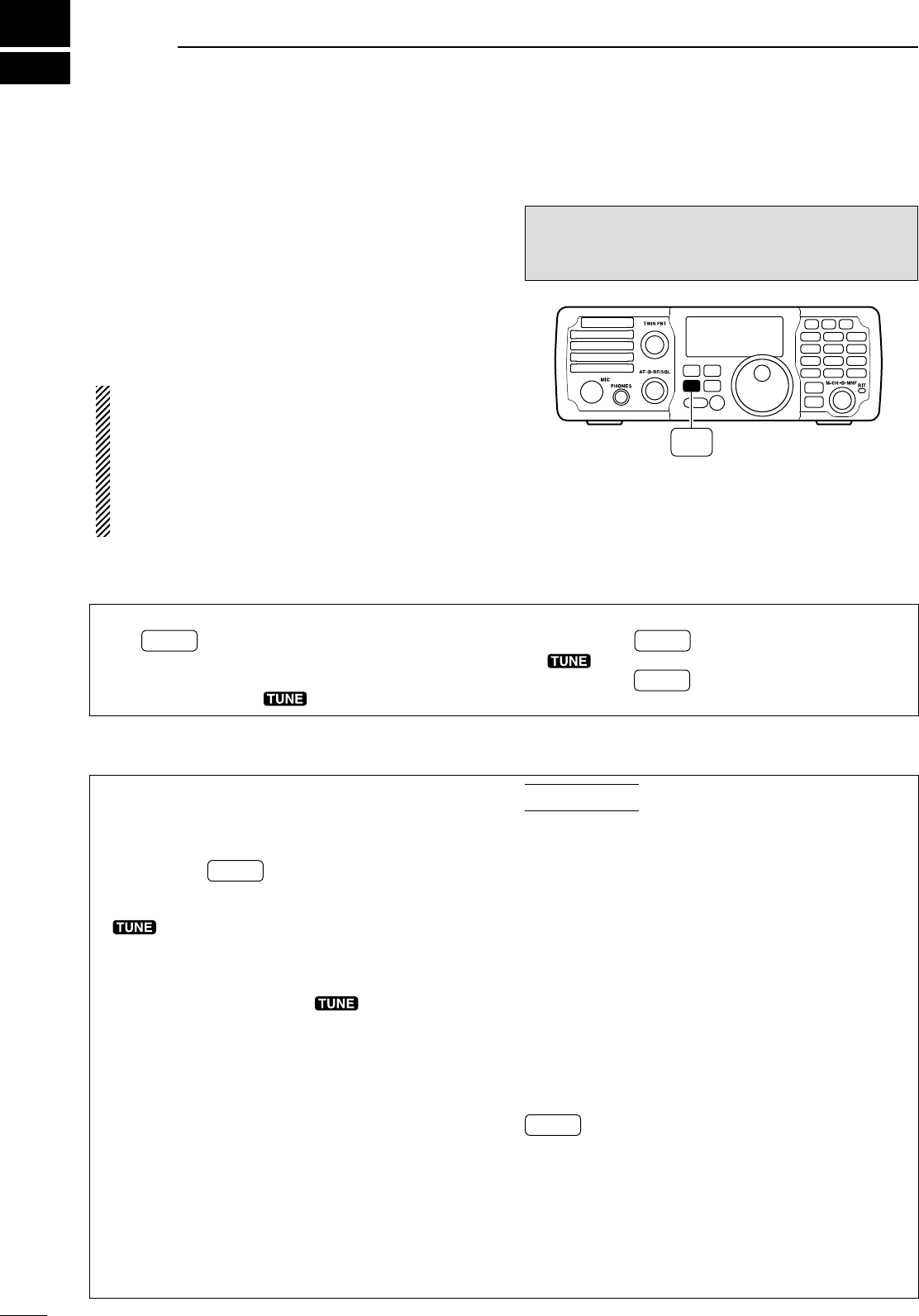
9
67
ANTENNA TUNER OPERATION
N Optional AT-180 AUTOMATIC ANTENNA TUNER operation
The AT-180 automatic antenna tuner matches the
IC-7200 to the connected antenna automatically.
Once the tuner matches an antenna, the variable
capacitor settings are memorized as a preset point
for each frequency range (100 kHz steps). Therefore,
when you change the frequency range, the variable
capacitors are automatically preset to the memorized
point.
NOTE:
• The AT-180 can match both HF and 50 MHz
bands. However, operation is different for the HF
and 50 MHz bands.
• When connecting the AT-180, the IC-7200’s out-
put power must be more than 10 W. Otherwise,
the AT-180 may not be tuned correctly. (AT-180’s
minimum operating input power is 8 W.)
CAUTION: NEVER transmit with the tuner ON
when no antenna is connected. This will damage
both the transceiver and antenna tuner.
MODE
TUNER
TS
FILTER
SPCH
V/M
A/B
SPLIT
M-CL
SCAN
SET
ATT
P
.
AMP
COMP
VOX
MNF
RIT
123
456
78
0
50
28
1814
10
21 24
=
7
3.5
1.8
F-INP
M-CH/RIT
ENT
BAND
GENE
9
.
AGC
MW
ANF
METER
NR
NB
TUNER
D Tuner operation
• For the HF band:
Push TUNER to turn the tuner ON. The antenna is
tuned automatically during transmission when the
antenna SWR is higher than 1.5:1.
• When the tuner is ON, “ ” indication appears.
• For the 50 MHz band:
Push and hold TUNER for 1 sec. to tune the antenna.
If “ ” indicator blinks slowly while transmitting,
push and hold TUNER for 1 sec. again to re-tune the
antenna.
D Manual tuning
During SSB operation on HF bands at low voice lev-
els, the AT-180 may not be tuned correctly. In such
cases, manual tuning is helpful.
Push and hold TUNER for 1 sec. to start manual tun-
ing.
• When CW mode is selected, a side tone is emitted, and
“” indicator blinks; then, the previous mode is se-
lected.
If the tuner cannot reduce the SWR to less than
1.5:1 after 20 sec. of tuning, “ ” indicator disap-
pears. In this case, check the following:
• the antenna connection and feedline
• the antenna SWR (p. 30; meter function, p 60;
Measuring SWR)
Through inhibit (HF bands only)
The AT-180 has a through inhibit condition. When
selecting this condition, the tuner can be used at
poor SWR’s. In this case, automatic tuning in the
HF bands activates only when exceeding SWR 3:1.
Therefore, manual tuning is necessary each time you
change the frequency. Although termed “through in-
hibit,” the tuner will be set to the “through” configura-
tion if the SWR is higher than 3:1 after tuning.
CONVENIENT
• Tuner sensitive condition (HF bands only)
If you require critical tuning at any time during trans-
mission, select the tuner sensitive condition.
See p. 68 for selection.
• Automatic tuner start (HF bands only)
If you want to turn OFF the tuner under conditions
of VSWR 1.5:1 or less, use “automatic tuner on” and
turn the tuner OFF. See p. 76 for the automatic tuner
function.
• PTT tune function (p. 76)
The AT-180 is tuned when [PTT] is pushed after the
frequency is changed (more than 1%) if the AT-180 is
turned ON. This function removes the “push and hold
TUNER ” operation and activates first transmission
on the new frequency.
This function is turned ON in the set mode.
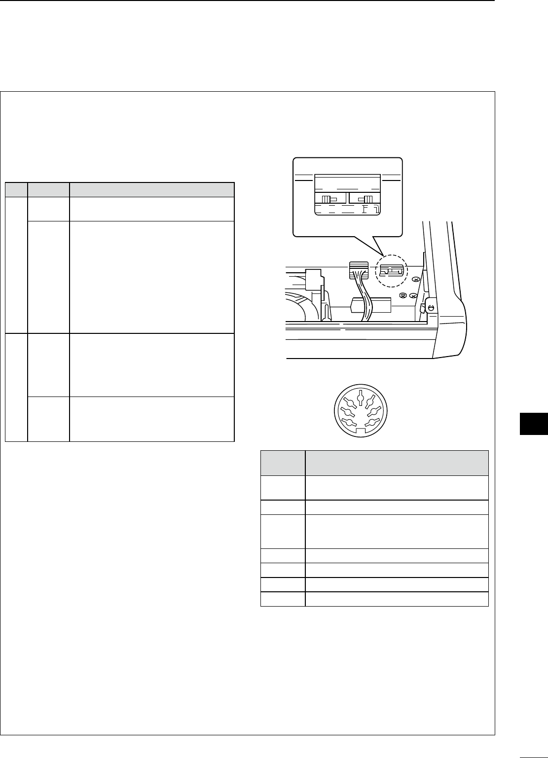
68
9
ANTENNA TUNER OPERATION
1
2
3
4
5
6
7
8
9
10
11
12
13
14
15
16
17
18
19
20
21
N AT-180 internal switch description
The optional AT-180 has 3 operating configurations
for HF band operation. Select a suitable configura-
tions according to your antenna system.
q Remove the top cover of the AT-180.
w Set the tuner switches to the desired positions ac-
cording to the table below.
SW Position Operation
S1
A
(default)
The tuner operating condition is set by
S2 described below.
BTHROUGH INHIBIT
The tuner tunes the antenna even when
the antenna has poor SWR (up to VSWR
3:1 after tuning). In this case, manual tun-
ing is necessary each time you change
the frequency although the tuner auto-
matically starts tuning when the VSWR
is higher than 3:1. This setting is called
“through inhibit,” however, the tuner is
set to “through” if the VSWR is higher
than 3:1 after tuning.
S2
CTUNER SENSITIVE CONDITION
The tuner tunes each time you transmit
(except SSB mode). Therefore, the lowest
SWR is obtained at any given time.
For SSB mode, the same condition as
the “D” position.
D
(default)
NORMAL
The tuner tunes when the SWR is higher
than 1.5:1. Therefore, the tuner activates
only when tuning is necessary.
• Specifications for the AT-180
• Frequency coverage : 1.8–54 MHz
• Input impedance : 50 Ω
• Maximum input power : 120 W
• Minimum tuning power : 8 W
•
Matching impedance range
: 16.7–150 Ω (HF band)
20–125 Ω (50 MHz band)
• Tuning accuracy : Less than SWR 1.5:1
• Insertion loss : Less than 1.0 dB
(after tuning)
•
Power supply requirements
: 13.8 V DC/1 A (supplied
from the transceiver’s
ACC socket)
• Dimensions (mm/in) :
167(W) × 58.6(H) × 225(D)
6
9
⁄
16
(W) × 2
5
⁄
17
(H) × 8
7
⁄
8
(D)
• Weight (approx.) : 2.3 kg; 5 lb
1
1
⁄
8
oz
• Supplied accessories : Coaxial cable (1 m),
ACC cable (DIN 13 pins)
• AT-180 inside top cover
S2 S1
DC BA
• Connector information for ACC(2) socket
ACC 2
1
2
3
4
76
5
PIN NO./
NAME DESCRIPTION
q 8 V Regulated 8 V output.
(10 mA max.)
w GND Connects to ground.
e SEND
Input/output pin.
Goes to ground when transmitting (20 mA max).
When grounded, transmits.
r BAND Band voltage output.
t ALC ALC output voltage (–4 to 0 V).
y NC No connection.
u 13.8 V 13.8 V output when power is ON (1 A max).
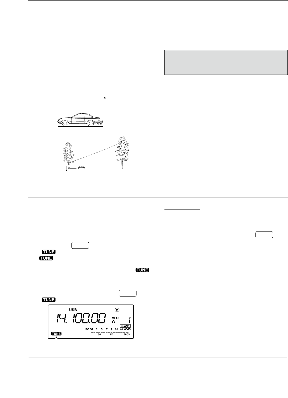
69
9ANTENNA TUNER OPERATION
N Optional AH-4 AUTOMATIC ANTENNA TUNER operation
The AH-4 matches the IC-7200 to a long wire antenna
more than 7 m/23 ft long (3.5 MHz and above).
• See p. 14 for connection.
• See the AH-4 instruction manual for AH-4 installation and
antenna connection details.
AH-4 setting example:
For mobile operation
For outdoor operation
Long wire
Optional AH-2b
antenna element
R DANGER!: HIGH VOLTAGE!
NEVER touch the antenna element while tuning or
transmitting.
NEVER operate the AH-4 without an antenna wire.
The tuner and transceiver will be damaged.
NEVER operate the AH-4 when it is ungrounded.
Transmitting before tuning may damage the trans-
ceiver. Note that the AH-4 cannot tune when using a
1⁄2λ long wire or on a multiple of that frequency.
D AH-4 operation
Tuning is required for each frequency. Be sure to
re-tune the antenna before transmitting when you
change the frequency—even slightly.
q Set the desired frequency in an HF band.
• The AH-4 will not operate on frequencies outside of
ham bands.
w Push and hold TUNER for 1 sec.
• “ ” indicator blinks while tuning.
e “ ” indicator is still ON after the tuning is
completed.
• When the connected wire cannot be tuned, “ ”
indicator goes out, and the AH-4 is bypassed and the
antenna wire is connected to the antenna connector
on the transceiver directly.
r To bypass the AH-4 manually, push TUNER .
• “ ” indicator goes out.
Appears when the antenna tuner ON.
Blinks while tuning.
CONVENIENT
• PTT tune function (p. 76)
The AH-4 is always tuned when [PTT] is pushed
after the frequency is changed (more than 1%). This
function removes the “push and hold TUNER ” op-
eration and activates first transmission on the new
frequency.
This function is turned ON in the set mode.
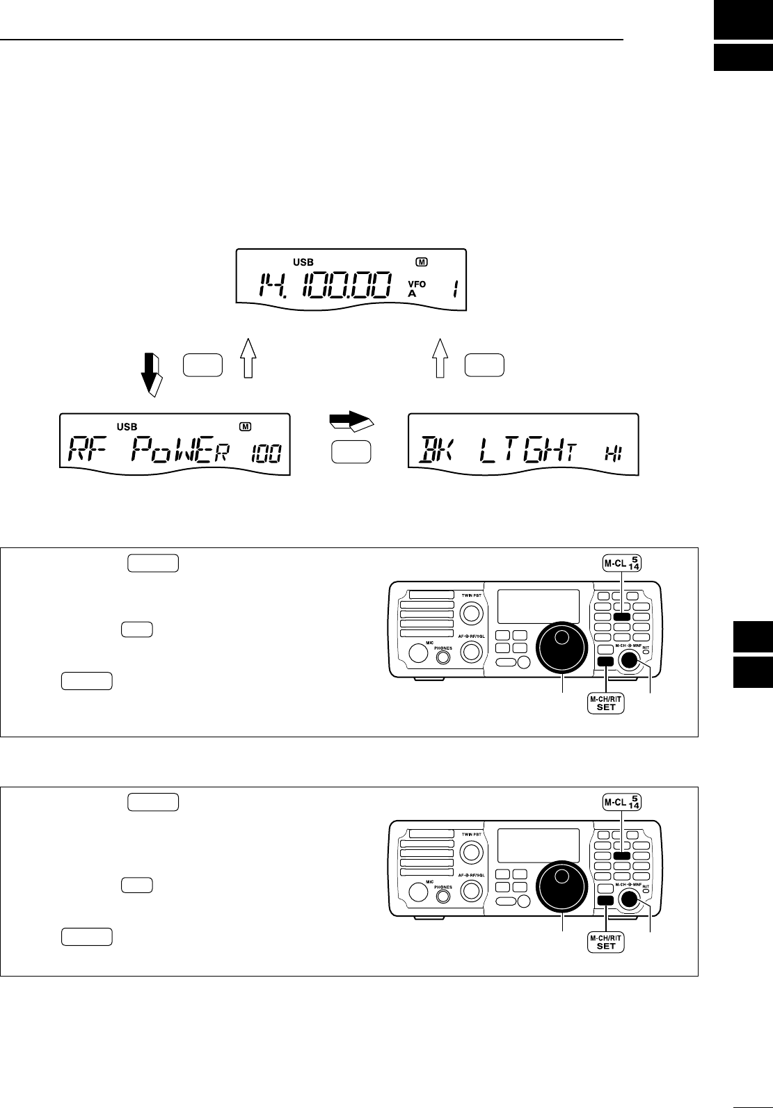
10
70
SET MODE
1
2
3
4
5
6
7
8
9
10
11
12
13
14
15
16
17
18
19
20
21
N General
Set mode is used for programming infrequently
changed values or conditions of functions.
The IC-7200 has 2 separate set modes: quick set
mode and set mode.
SET
M-CH/RIT
SET
M-CH/RIT
SET
M-CH/RIT
Push and hold
for 1 sec.
Push
momentarily
Push
momentarily
Push and hold
for 1 sec.
Quick set mode Set mode
Normal operation mode
D Quick set mode operation
q Push and hold M-CH/RIT
SET for 1 sec. to enter the
quick set mode.
w Rotate [M-CH] to select the desired item.
e Set the desired condition or value using [DIAL].
• Push and hold M-CL for 1 sec. to select the default
condition or value.
r Repeat w and e to set other items.
t Push M-CH/RIT
SET to exit the quick set mode and re-
turn to normal operation. [DIAL]
MODE
TUNER
TS
FILTER
SPCH
V/M
A/B
SPLIT
M-CL
SCAN
SET
ATT
P
.
AMP
COMP
VOX
MNF
RIT
123
456
78
0
50
28
1814
10
21 24
=
7
3.5
1.8
F-INP
M-CH/RIT
ENT
BAND
GENE
9
.
AGC
MW
ANF
METER
NR
NB
[M-CH]
D Set mode operation
q Push and hold M-CH/RIT
SET for 1 sec. to enter the
quick set mode.
w Repeat step q again to enter the set mode.
e Rotate [M-CH] to select the desired item.
r Set the desired condition or value using [DIAL].
• Push and hold M-CL for 1 sec. to select the default
condition or value.
t Repeat e and r to set other items.
y Push M-CH/RIT
SET to exit the set mode and return to
normal operation.
[DIAL]
MODE
TUNER
TS
FILTER
SPCH
V/M
A/B
SPLIT
M-CL
SCAN
SET
ATT
P
.
AMP
COMP
VOX
MNF
RIT
123
456
78
0
50
28
1814
10
21 24
=
7
3.5
1.8
F-INP
M-CH/RIT
ENT
BAND
GENE
9
.
AGC
MW
ANF
METER
NR
NB
[M-CH]
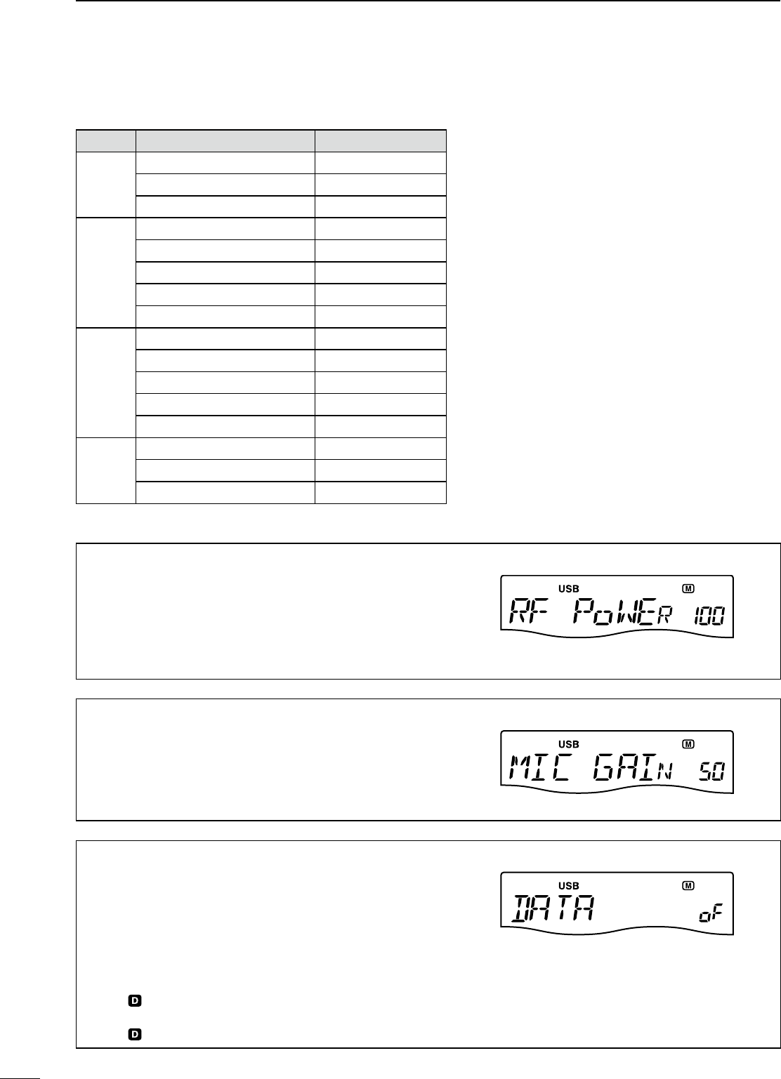
N Quick set mode
Mode Set mode item Default setting
SSB
1 RF POWER 100%
2 MIC GAIN 50%
3 DATA MODE OFF
CW
1 RF POWER 100%
2 KEY SPEED 20WPM
3 CW PITCH 600Hz
4 SIDE TONE LEVEL 30%
5 SIDE TONE LIMIT ON
RTTY
1 RF POWER 100%
2 TWIN PEAK FILTER OFF
3 RTTY MARK TONE 2125Hz
4 RTTY SHIFT 170Hz
5 RTTY KEY POLARITY NORMAL
AM
1 RF POWER 100%
2 MIC GAIN 50%
3 DATA MODE OFF
RF power (all modes)
This item adjusts the RF output power. The RF output
power can be adjusted from L (Low), 1% to 100% in 1%
steps.
100%
(
default
)
Mic gain (SSB/AM modes)
This item adjusts microphone gain from 0% to 100% in
1% steps.
50%
(
default
)
Data mode (SSB/AM modes)
This item turns the data mode ON or OFF.
When the data mode is turned ON, the audio input from
the [ACC] connector* is used for transmission instead of
[MIC] connector and the speech compressor function is
turned OFF.
* The desired connector can be selected. (p. 77)
on : Data mode operation is enabled.
(“ ” appears.)
oF : Data mode operation is disabled.
(“ ” disappears.)
OFF
(
default
)
71
10 SET MODE
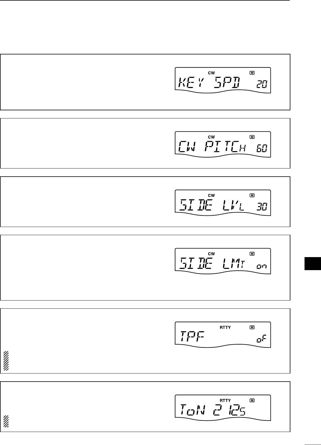
72
10
SET MODE
1
2
3
4
5
6
7
8
9
10
11
12
13
14
15
16
17
18
19
20
21
Key speed (CW mode)
This item adjusts the CW key speed. The key speed can
be selected from 6 to 60* wpm.
* 39, 43, 45, 47, 49, 51, 53, 55, 56, 58 and 59 cannot be
selected.
20 WPM
(
default
)
CW pitch (CW mode)
This item adjusts the CW receive pitch. The pitch can be
selected from 300 to 900 Hz in 10 Hz steps.
600 Hz
(
default
)
Side tone level (CW mode)
This item adjusts the CW side tone level from 0% to
100% in 1% steps.
30%
(
default
)
Side tone level limit (CW mode)
This item allows you to set a maximum volume level for
CW side tone. CW side tone is linked to the [AF] control
until a specified volume level is reached—further rotation
of the [AF] control will not increase the volume of the CW
side tones.
on : CW side tone level is limited with the [AF] control.
oF : CW side tone level is linked to the [AF] control.
ON
(
default
)
Twin peak filter (RTTY mode)
This item turns the twin peak filter ON or OFF.
on : Twin peak filter is ON.
oF : Twin peak filter is OFF.
NOTE: The RTTY mark frequency (2125 Hz) and shift
width (170 Hz) are automatically set when the twin
peak filter is ON.
OFF
(
default
)
RTTY mark tone (RTTY mode)
This item selects the RTTY mark frequency. There are 3
selectable values: 1275, 1615 and 2125 Hz.
NOTE: 2125 Hz is automatically set when the twin
peak filter is ON. 2125 Hz
(
default
)
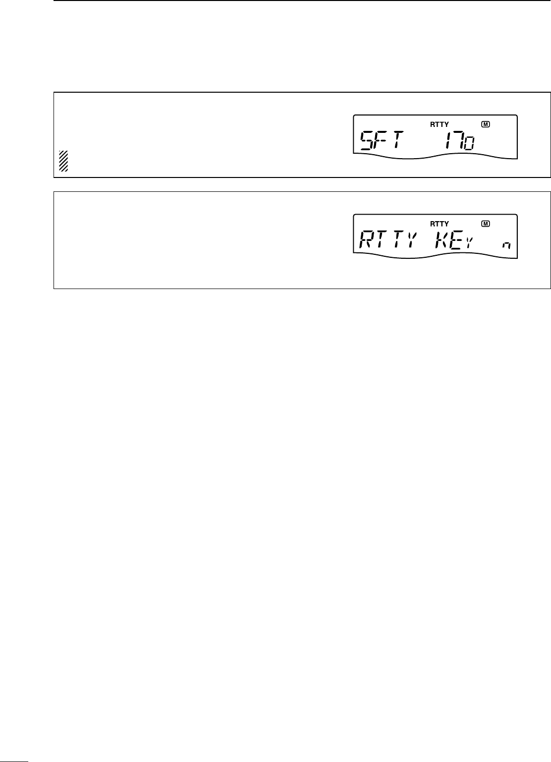
73
N Quick set mode (Continued)
RTTY shift width (RTTY mode)
This item adjusts the RTTY shift width. There are 4
selectable values: 170, 200, 425 and 850 Hz.
NOTE: 170 Hz is automatically set when the twin peak
filter is ON. 170 Hz
(
default
)
RTTY key polarity (RTTY mode)
This item selects the RTTY keying polarity. Normal or
reverse keying polarity can be selected.
When reverse polarity is selected, Mark and Space are
reversed.
n (normal) : Key open/close = Mark/Space
r (reverse) : Key open/close = Space/Mark
NORMAL
(
default
)
10 SET MODE
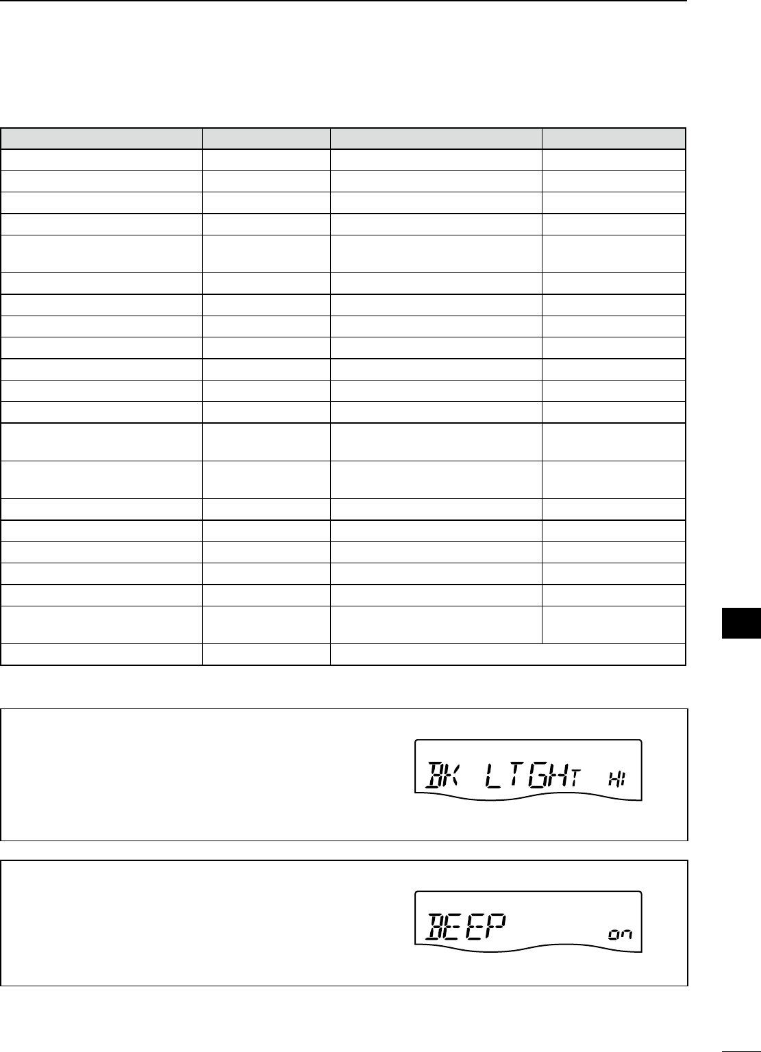
74
10
SET MODE
1
2
3
4
5
6
7
8
9
10
11
12
13
14
15
16
17
18
19
20
21
N Set mode
Set mode item Default setting Set mode item Default setting
1 LCD BACKLIGHT HIGH 22 SCAN RESUME ON
2 BEEP ON 23 MAIN DIAL AUTO TS HIGH
3 BAND EDGE BEEP ON 24 DIAL 1⁄4OFF
4 BEEP LEVEL 50% 25 MIC UP/DOWN SPEED HIGH
5 BEEP LEVEL LIMIT ON 26 SSB/CW SYNCHRONOUS
TUNING OFF
6 RF/SQL CONTROL RF + SQL 27 CW NORMAL SIDE LSB
7 METER PEAK HOLD ON 28 BREAK-IN OFF
8 QUICK SPLIT ON 29 BREAK-IN DELAY 7.5 DOTS
9 SPLIT LOCK OFF 30 DOT/DASH RATIO 1:1:3.0
10 XFC OFF 31 PADDLE POLARITY NORMAL
11 AUTO TUNE OFF 32 KEYER TYPE ELEC-KEY
12 PTT TUNE OFF 33 MIC UP/DOWN KEYER OFF
13 MODULATION INPUT
(DATA OFF) MIC/ACC 34 MODE SELECT (SSB) ON
14 MODULATION INPUT
(DATA ON) ACC 35 MODE SELECT (CW) ON
15 USB LEVEL 50% 36 MODE SELECT (RTTY) ON
16 SPEECH LEVEL 50% 37 MODE SELECT (AM) ON
17 SPEECH LANGUAGE ENGLISH 38 CI-V BAUD RATE AUTO
18 SPEECH SPEED HIGH 39 CI-V ADDRESS 76H
19 SPEECH S-LEVEL ON 40 CI-V TRANSCEIVE ON
20 SPEECH [MODE] KEY OFF 41
REFERENCE FREQUENCY
ADJUSTMENT
Default setting is differ-
ent for each transceiver.
21 SCAN SPEED HIGH
LCD Backlight
This item adjusts the brightness of the LCD from HI
(High), Lo (Low) or oF (Off).
Hi
g
h
(
default
)
Beep
A beep sounds each time a key is pushed to confirm it.
This function can be turned OFF for silent operation.
on : Confirmation beep ON
oF : Confirmation beep OFF
The volume level can be set in “Beep Level” as below. ON
(
default
)
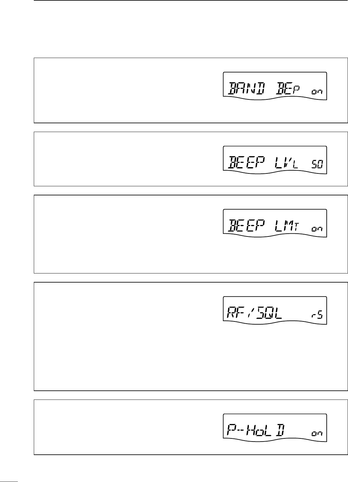
75
10 SET MODE
N Set mode (Continued)
Band Edge Beep
A beep sounds when an operating frequency enters or
exits an amateur band. This function is independent from
“Beep” (the confirmation beep) setting as above.
on : Band edge beep ON
oF : Band edge beep OFF
The volume level can be set in “Beep Level” as below.
ON
(
default
)
Beep Level
This item sets the maximum volume level for the con-
firmation beep and band edge beep tones from 0% to
100% in 1% steps.
When beep tones are set to OFF, this setting has no ef-
fect. 50%
(
default
)
Beep Level Limit
Turn the beep tones output level limiting capability ON
and OFF for the confirmation and band edge beep tones.
When this item is set to ON, the beep tones are linked to
the [AF] control until rotation of the [AF] control reaches
to the specified level—further rotation will not increase
the volume of the beep tones.
on : Beep level is limited with the [AF] control
oF : Beep level is linked to the [AF] control
ON
(
default
)
RF/SQL Control
The [RF/SQL] control can be set as the RF/squelch con-
trol, the squelch control only (RF gain is fixed at maxi-
mum) or Auto (RF gain control in SSB, CW and RTTY;
squelch control in AM).
See pgs. 4, 30 for details.
rS (RF+SQL) : [RF/SQL] control is set as the RF/squelch
control
Sq (SQL) : [RF/SQL] control is set as the squelch
control
At (AUTO) : [RF/SQL] control is set as the RF gain
control in SSB, CW and RTTY; squelch
control in AM
RF + SQL
(
default
)
Meter Peak Hold
This item turns the meter peak hold function ON or OFF.
on : The highest activated segment of the meter remains
visible for 0.5 sec.
oF : The meter functions normally.
ON
(
default
)
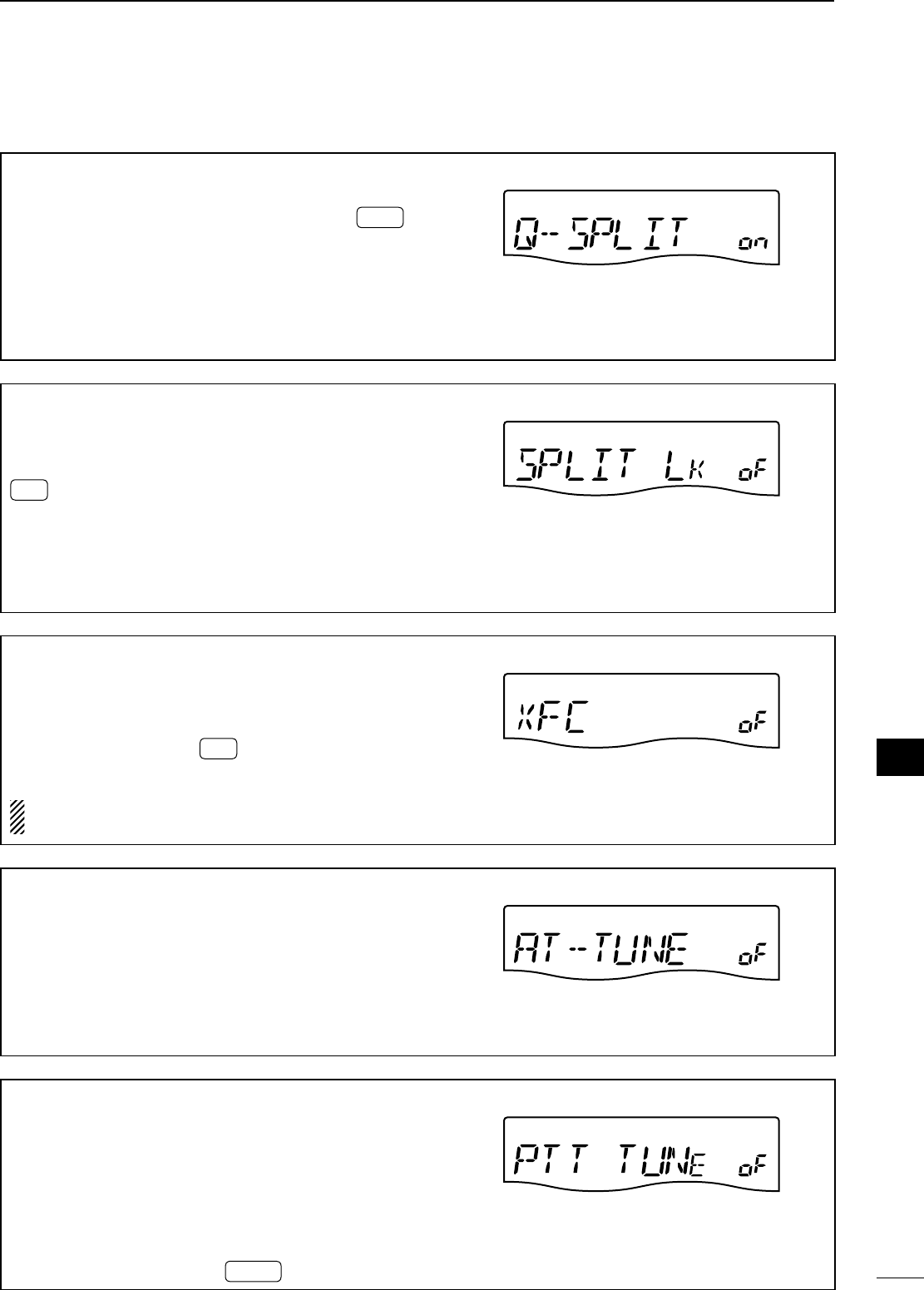
76
10
SET MODE
1
2
3
4
5
6
7
8
9
10
11
12
13
14
15
16
17
18
19
20
21
Quick Split
This item turns the quick split function ON or OFF.
When this item is set to ON, push and hold SPLIT for
1 sec. to set the undisplayed VFO frequency and oper-
ating mode are set the same as the displayed VFO fre-
quency and operating mode.
See pgs. 58, 59 for details.
on : The quick split function ON
oF : The quick split function OFF
ON
(
default
)
Split Lock
This item turns the split lock function ON or OFF.
When this item is set to ON, the transmit frequency can
be adjusted by rotating [DIAL] while pushing and holding
RIT * even if the lock function is activated.
* The transmit frequency check function (“XFC”; p. 76) must be
turned ON in advance.
See p. 59 for split frequency operation details.
on : The split lock function ON
oF : The split lock function OFF
OFF
(
default
)
XFC
This item turns the XFC (transmit frequency check) func-
tion ON or OFF.
on : The transmit frequency can be monitored while
pushing and holding RIT
oF : The transmit frequency check function OFF
NOTE: When the XFC function is turned ON, the RIT
calculation function (p. 44) is not available.
OFF
(
default
)
Auto Tune
The optional AT-180 ANTENNA TUNER has an automatic
start capability which starts tuning if the SWR is higher
than 1.5:1.
on : The automatic tune starts even when the tuner is
turned OFF during HF bands operation.
oF : The tuner remains OFF even when the SWR is poor
(1.5:1)
OFF
(
default
)
PTT Tune
Tuning of the internal antenna tuner can be started auto-
matically at the moment [PTT] is pushed after the operat-
ing frequency is changed (more than 1% from last-tuned
frequency).
When an optional AT-180 ANTENNA TUNER is connected,
the tuner function must be turned ON in advance.
on :
Tuning starts when [PTT] is pushed on a new frequency.
oF : Tuning starts only when TUNER is pushed.
OFF
(
default
)
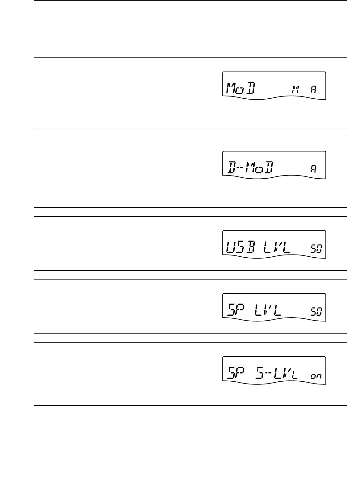
77
10 SET MODE
N Set mode (Continued)
Modulation input (Data OFF)
Selects the desired connector(s) for modulation input
when SSB data/AM data mode is not in use.
M (MIC) : Use the signals from [MIC].
A (ACC) : Use the signals from [ACC] (pin11).
M A (MIC/ACC) : Use the signals from [MIC] and [ACC]
(pin11).
U (USB) : Use the signals from [USB].
MIC/ACC
(
default
)
Modulation input (Data ON)
Selects the desired connector(s) for modulation input
when SSB data/AM data mode is in use.
M (MIC) : Use the signals from [MIC].
A (ACC) : Use the signals from [ACC] (pin11).
M A (MIC/ACC) : Use the signals from [MIC] and [ACC]
(pin11).
U (USB) : Use the signals from [USB].
ACC
(
default
)
USB Level
Sets the input modulation level of the USB jack, within
0% to 100% in 1% steps.
50%
(
default
)
Speech Level
This item adjusts the volume level for the speech function
from 0% to 100% in 1% steps.
50%
(
default
)
Speech S-level
Frequency, mode and signal level can be announced by
the voice synthesizer. The signal level announcement
can be deactivated if desired.
When “oF” is selected, the signal level is not announced.
on : Signal level announcement
oF : No signal level announcement
ON (default)
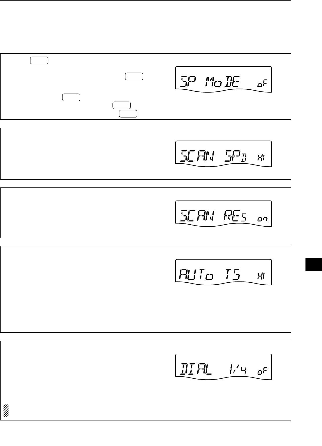
78
10
SET MODE
1
2
3
4
5
6
7
8
9
10
11
12
13
14
15
16
17
18
19
20
21
Speech MODE Key
This item selects whether the operating mode an-
nounced with the speech synthesizer when MODE is
pushed.
When “on” is selected, the selected operating mode is
announced at pushing MODE .
on : Operating model announcement with MODE .
oF : No operating mode announcement with MODE .
OFF
(
default
)
Scan Speed
This item sets the rate at which channels or frequencies
are scanned during scan operations.
High and low can be selected.
HI : Fast scan.
Lo : Slow scan. Hi
g
h
(
default
)
Scan Resume
This item turns the scan resume function ON or OFF.
on : Scan resumes 10 sec. after stopping on a signal (or
2 sec. after a signal disappears).
oF : Scan does not resume after stopping on a signal.
ON
(
default
)
Main Dial Auto TS
This item sets the auto tuning step function. When ro-
tating [DIAL] rapidly, the tuning step rate adapts as se-
lected.
There are 2 type of auto tuning steps: HI (Fastest) and
Lo (Faster).
HI : Approx. 5 times faster when the tuning step is set to
1 kHz or smaller steps; approx. 2 times faster when
the tuning step is set to 5 kHz or larger steps.
Lo : Approx. 2 times faster
oF : Auto tuning step is turned OFF.
Hi
g
h
(
default
)
Dial ¼
This item turns the ¼-speed tuning function ON or OFF
in CW, RTTY and SSB data modes.
on : The ¼-speed tuning function ON for critical tuning.
While operating in CW/RTTY/SSB data/AM data,
the dial sensitivity is reduced to ¼ of normal.
oF : The ¼-speed tuning function OFF.
NOTE: This function is only available when the pro-
grammable tuning step is OFF (p. 26).
OFF
(
default
)
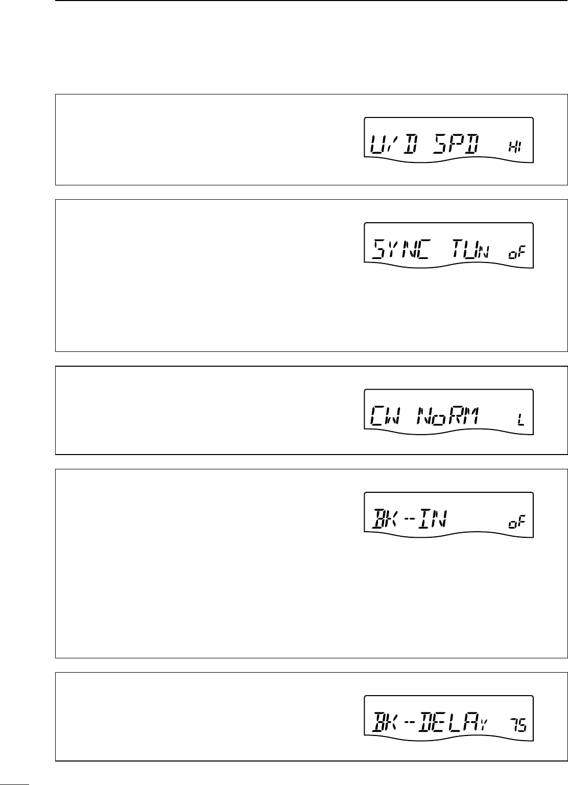
79
10 SET MODE
N Set mode (Continued)
Mic Up/Down Speed
This item sets the rate at which frequencies are scanned
when the microphone [UP]/[DN] keys are pushed and
held.
HI : High speed (50 tuning steps/sec.)
Lo : Low speed (25 tuning steps/sec.) Hi
g
h
(
default
)
SSB/CW Synchronous Tuning
This item turns the displayed frequency shift function
from ON or OFF.
When this function is set to ON, the received signal
will remain the same even when the operating mode is
changed between SSB and CW.
The amount of frequency shift will change according to
the CW pitch setting.
on : The displayed frequency shifts when the operating
mode is changed between SSB and CW.
oF : The displayed frequency does not shift.
OFF
(
default
)
CW Normal Side
Selects the carrier point of CW mode from LSB and USB.
L (LSB) : LSB is the normal mode.
U (USB) : USB is the normal mode.
LSB
(
default
)
Break-In
This item selects break-in type for CW operation.
Full break-in (QSK) activates the receiver between trans-
mitted dots and dashes. This is useful when operating
contests, when “fast responses” are common.
Semi break-in keeps the receiver quiet between dots and
dashes and automatically returns to receive after a pre-
set time from when you stop keying.
When break-in is turned off, the key or paddle can gener-
ate side tones (selectable in quick set mode) but will not
transmit.
oF : No break-in operation.
SE (Semi) : Semi break-in operation.
FL (Full) : Full break-in operation.
OFF
(
default
)
Break-In Delay
This item adjusts break-in delay time for CW semi
break-in operation.
The delay time is selectable from 0.2 to 13.0 (dots) in 0.1
(dots) steps.
7.5 dots
(
default
)
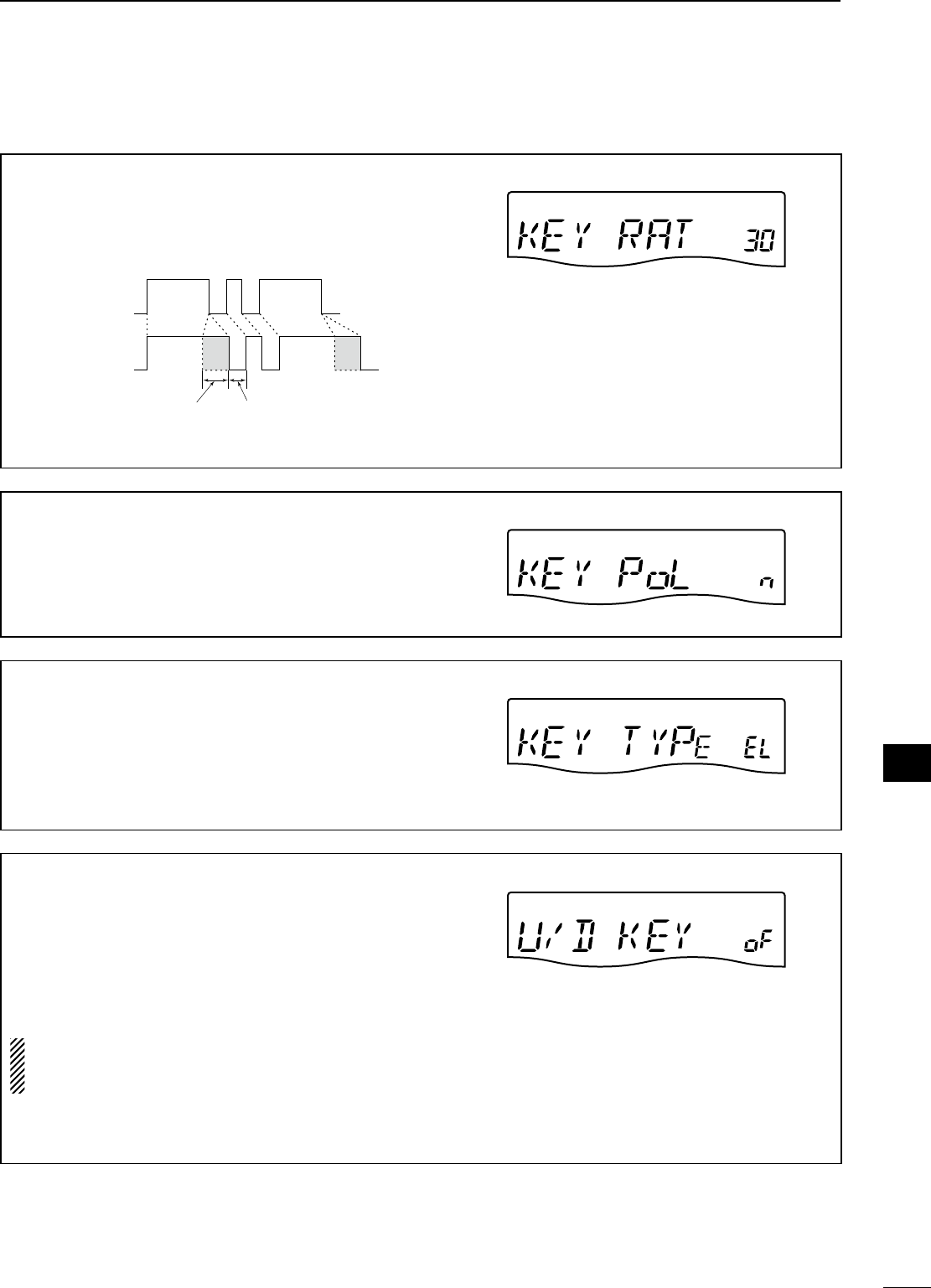
80
10
SET MODE
1
2
3
4
5
6
7
8
9
10
11
12
13
14
15
16
17
18
19
20
21
Dot/Dash Ratio
This item sets the internal electronic keyer dot/dash ratio.
1:1:2.8 to 1:1:4.5 (in 0.1 steps) can be selected.
Keying weight example: Morse code “K”
DASH
Weight setting:
1:1:3 (default)
Weight setting:
Adjusted
DASH
DOT (Fixed*)
Adjustable range SPACE (Fixed*)
*SPACE and DOT length can be adjusted with
“Key speed” only in the quick set mode.
1:1:3.0
(
default
)
Paddle Polarity
This item sets the paddle polarity.
n (Normal) : Normal polarity.
r (Reverse) : Reverse polarity.
Normal
(
default
)
Keyer Type
This item selects the keyer type for the [KEY] connector
on the rear panel.
EL : Internal electronic keyer is selected.
bG : Internal electronic keyer is activated as BUG key.
St :
Internal electronic keyer is turned OFF, and a
straight key or external electronic keyer can be used.
ELEC-KEY
(
default
)
Mic Up/Down Keyer
This item allows you to set the microphone [UP]/[DN]
switches to be used as a paddle.
on : [UP]/[DN] switches can be used as a paddle for CW
mode operation.
oF : [UP]/[DN] switches cannot be used as a paddle for
CW mode operation.
NOTE: When “ON” is selected, the frequency and
memory channel cannot be changed using the [UP]/
[DN] switches.
See p. 82 for the CW paddle connection to the MIC con-
nector.
OFF (default)
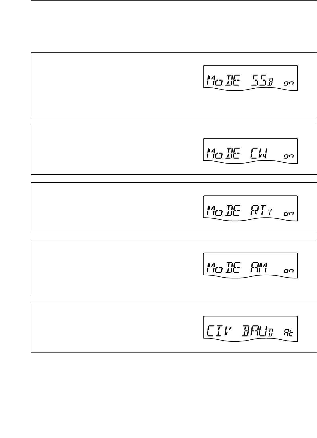
81
10 SET MODE
N Set mode (Continued)
Mode Select (SSB)
This item inhibits the selection of SSB (LSB/USB)
modes, and allows you to simplify operation.
For example if you are operating mobile and only plan on
using AM mode, set all other modes (SSB, CW, RTTY) to
OFF, thereby making selection of AM quick and easy.
on : SSB modes are selectable.
oF : SSB modes are inhibited.
ON
(
default
)
Mode Select (CW)
This item inhibits the selection of CW/CW-R modes, and
allows you to simplify operation.
on : CW modes are selectable.
oF : CW modes are inhibited. ON (default)
Mode Select (RTTY)
This item inhibits the selection of RTTY/RTTY-R modes,
and allows you to simplify operation.
on : RTTY modes are selectable.
oF : RTTY modes are inhibited. ON (default)
Mode Select (AM)
This item inhibits the selection of AM mode, and allows
you to simplify operation.
on : AM modes are selectable.
oF : AM modes are inhibited.
ON (default)
CI-V Baud Rate
Sets the CI-V data transfer rate. 300, 1200, 4800, 9600,
19200 bps and Auto are available.
When Auto is selected, the baud rate is automatically set
according to the connected controller or remote controller.
Auto (default)
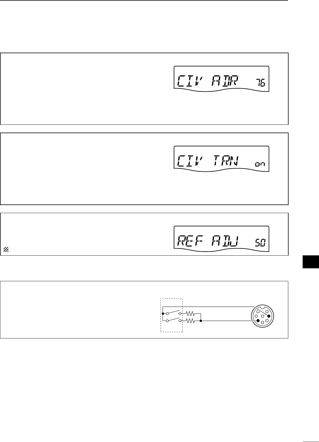
CI-V Address
To distinguish equipment, each CI-V transceiver has its
own Icom standard address in hexadecimal code.
The IC-7200’s address is 76h.
When 2 or more IC-7200s are connected to an optional
CT-17 CI-V LEVEL CONVERTER, rotate [DIAL] to select
a different address for each IC-7200 in the range 01h to
7Fh.
76 : Address of 76h
76h (default)
CI-V Transceive
Transceive operation is possible with the IC-7200 con-
nected to other Icom HF transceivers or receivers.
When “ON” is selected, changing the frequency, operat-
ing mode, etc. on the IC-7200 automatically changes
those of connected transceivers (or receivers) and vice
versa.
on : Transceive ON
oF : Transceive OFF
ON (default)
Reference Frequency Adjustment
Adjusts the internal reference signal frequency within 0%
to 100% range in 1% steps during frequency calibration.
NOTE: Default setting is different for each transceiver.
D Paddle operation from [MIC] connector
Connect a CW paddle as at right to operate an elec-
tronic keyer from the [MIC] connector.
• Be sure to select “Paddle Polarity,” “Keyer Type” and
“Mic Up/Down Keyer” in the set mode. (p. 80)
• Connect straight key to “DOT” side.
• Push both of “DOT” and “DASH” to activate the
squeeze operation. MIC connector
CW
paddle
DOT
DASH
3.9 kø ±5%
2.2 kø ±5%
MIC U/D e
GND y
82
10
SET MODE
1
2
3
4
5
6
7
8
9
10
11
12
13
14
15
16
17
18
19
20
21
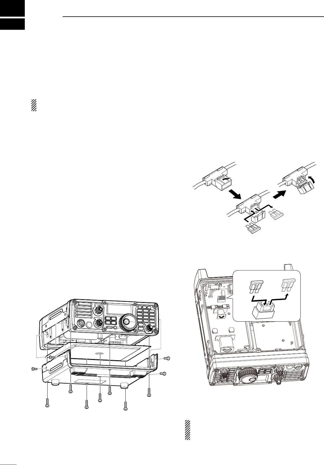
N Fuse replacement
If a fuse blows or the transceiver stops functioning,
try to find the source of the problem, and replace the
damaged fuse with a new, adequately rated fuse.
CAUTION: Disconnect the DC power cable
from the transceiver when changing a fuse.
The IC-7200 has two fuses (DC power cable fuses)
installed for transceiver protection.
• DC power cable fuses .............................. ATC 30 A
• Circuitry fuse .............................................. ATC 5 A
D DC power cable fuse replacement
Refer the figure illustrated at right for the DC power
cable fuse replacement.
D Circuitry fuse replacement
The 13.8 V DC from the DC power cable is applied to
all units in the IC-7200, except for the power amplifier,
through the circuitry fuse. This fuse is installed in the
PA unit.
q Remove the 11 screws, then remode the bottom
cover and the PA shielding plate as shown below.
ATC 30 A fuse
e Replace the circuitry fuse as shown in the diagram
as below.
Front panel
ATC 5 A fuse
r Replace the PA shielding plate, bottom cover and
screws to their original position.
Be sure the gasket is seated correctly, and do not
protrude from the transceiver when the PA shield-
ing plate is replaced.
11
83
MAINTENANCE
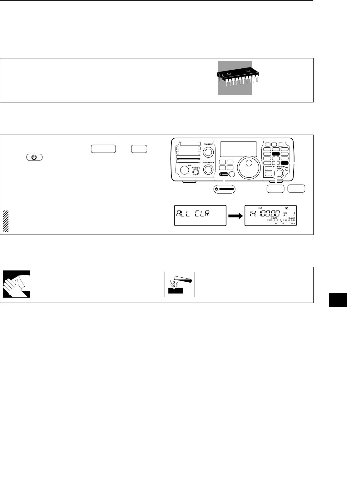
84
11
MENTENANCE
1
2
3
4
5
6
7
8
9
10
11
12
13
14
15
16
17
18
19
20
21
N Memory backup
All of the CPU’s memory is backed up by an EEP-
ROM (Electronically-Erasable Programmable Read-
Only Memory). All data you set, such as VFO,
memory, set mode contents, etc. are stored in this
EEPROM. There is no internal lithium battery.
N Resetting the CPU
q Make sure the transceiver power is OFF.
w While pushing and holding F-INP ENT
BAND and M-CL ,
push to turn power ON.
• The internal CPU is reset, and all memory data are
cleared.
• The transceiver displays its initial VFO frequencies
when resetting is complete.
e All quick set mode/set mode settings are returned
to default values. (p. 70)
Resetting CLEARS all programmed contents in
memory channels and returns default values in
quick set mode/set mode.
MODE
TUNER
TS
FILTER
SPCH
V/M
A/B
SPLIT
M-CL
SCAN
SET
ATT
P
.
AMP
COMP
VOX
MNF
RIT
123
456
78
0
50
28
1814
10
21 24
=
7
3.5
1.8
F-INP
M-CH/RIT
ENT
BAND
GENE
9
.
AGC
MW
ANF
METER
NR
NB
M-CL
5
14
F-INP ENT
BAND
N Cleaning
If the transceiver becomes dusty or dirty,
wipe it clean with a dry, soft cloth.
AVOID the use of strong chemical sol-
vents such as paint, thinner, benzene or
alcohol to clean the transceiver. These
may damage the transceiver’s surfaces.
12
85
TROUBLESHOOTING
The following chart is designed to help you correct
problems which are not equipment malfunctions.
If you are unable to locate the cause of a problem
or solve it through the use of this chart, contact your
nearest Icom Dealer or Service Center.
PROBLEM POSSIBLE CAUSE SOLUTION REF.
POWER SUPPLY
Power does not come
on when [PWR] is
pushed.
•
DC power cable is improperly connected.
• Reconnect the power cable correctly. p. 15
• Fuse is blown. • Check for the cause, then replace the
fuse with a spare one.
(Fuse is installed in the DC power cable)
p. 83
• Battery is exhausted if you are using a
12 V battery as the power source.
• Check the battery voltage. —
RECEIVE
No sound comes from
the speaker.
• Volume level is set too low. • Rotate [AF] clockwise to obtain a suit-
able listening level.
p. 29
• The squelch level is closed. • Tu r n [RF/SQL] to 10 o’clock position to
open the squelch.
p. 30
• The transceiver is in the transmit mode. • Release [PTT] on the microphone or
check the SEND line of an external unit,
if connected.
—
• An external speaker or headphones are
connected.
• Check the external speaker or head-
phone plug connection.
p. 14
Sensitivity is too low,
and only strong signals
are audible.
• The antenna is not connected properly. • Reconnect to the antenna connector. —
• The antenna feed line is cut or shorted. • Check the feed line and correct any im-
proper conditions.
—
• The antenna is not properly tuned. • Push TUNER to manually tune the an-
tenna.
p. 67
• The attenuator function is activated. • Push P.AMP
ATT to turn the function OFF. p. 45
• The antenna for another band is se-
lected.
• Select an antenna suitable for the oper-
ating frequency.
p. 67
Receive audio is dis-
torted.
• The operating mode is not selected cor-
rectly.
• Select a suitable operating mode. p. 29
Receive signal is dis-
torted by strong sig-
nals.
• The noise reduction is activated and the
noise reduction level is too high.
• Set the noise reduction level for maxi-
mum readability.
p. 50
• Noise blanker function is activated. • Push NB to turn the function OFF. p. 49
• Preamp is activated. • Push P.AMP
ATT to turn the function OFF. p. 45
The shift frequency of
the RIT function cannot
be added/subtracted.
• The XFC (transmit frequency check
function) is turned ON.
• Turn the XFC (transmit frequency check
function) OFF in set mode.
p. 76
PROBLEM POSSIBLE CASE SOLUTION REF.
TRANSMIT
Transmitting is impos-
sible.
• The operating frequency is not set in a
ham band.
• Set the frequency in a ham band. p. 25
Output power is too
low.
• Power is set to a lower power than max-
imum.
• Set the output power in quick set mode. p. 71
• Microphone gain is set too low. • Set microphone gain to a suitable level
in quick set mode.
p. 71
• The antenna is not connected properly. • Reconnect the antenna connector. —
• The antenna feed line is cut or shorted. • Check the feed line and correct any im-
proper conditions.
—
• The antenna is not properly tuned. • Push TUNER to manually tune the an-
tenna or test with dummy load.
p. 67
• The antenna for another band is se-
lected.
• Select an antenna suitable for the oper-
ating frequency.
p. 67
No contact possible
with other stations.
• RIT function is activated. • Push RIT to turn the function OFF. p. 44
• Split function is activated. • Push SPLIT to turn the function OFF. p. 58
Transmitted signals are
distorted.
• Microphone gain is set too high. • Set microphone gain to a suitable level
in quick set mode.
p. 71
• The compression level is set too high
with the speech compressor ON.
• Set compression level to a suitable po-
sition.
p. 57
DISPLAY
Displayed frequency
does not change prop-
erly.
• The dial lock function is activated. • Push
SPCH
to deactivate the function. p. 29
• The internal CPU has malfunctioned. • Reset the CPU. pgs. 21,
83
SCAN
Programmed scan
does not stop.
• [RF/SQL] is assigned to RF gain control
and squelch is open.
• Reset [RF/SQL] control assignment and
set it to the threshold point.
p. 30
Programmed scan
does not start.
• The same frequencies have been pro-
grammed in scan edge memory chan-
nels.
• Program different frequencies into scan
edge memory channels.
p. 62
Memory scan does not
start.
• 2 or more memory channels have not
been programmed.
• Program 2 or more memory channels. p. 62
MEMORY
The memory channels
cannot be selected
with rotating the [M-CH]
control.
• The [M-CH] control is in RIT control
mode.
• Push M-CH/RIT
SET to cancel the RIT func-
tion (RIT control indicator goes out).
p. 61
86
12
TROUBLESHOOTING
1
2
3
4
5
6
7
8
9
10
11
12
13
14
15
16
17
18
19
20
21
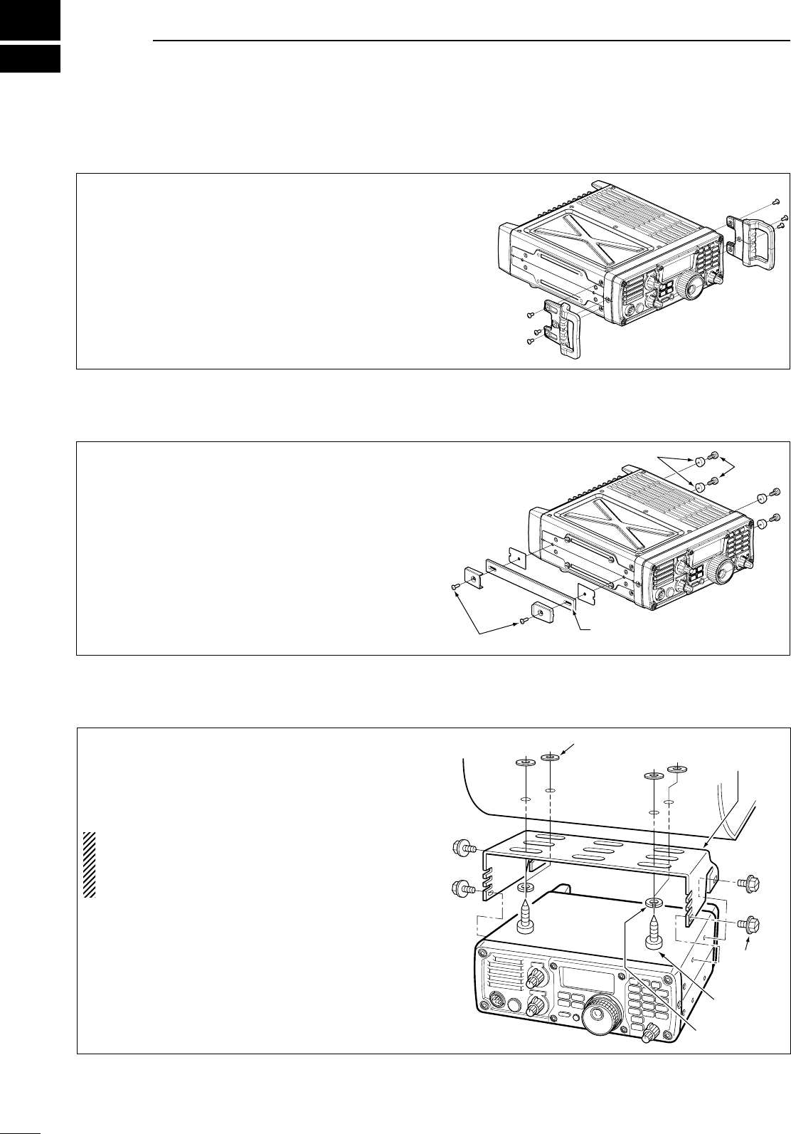
13
87
OPTION INSTALLATIONS
N MB-116 HANDLES installation
The optional MB-116 HANDLES are convenient when
moving the transceiver and can protect the face and
radio knobs during transport.
± Attach the MB-116 to the both sides of the trans-
ceiver with the supplied screws (M4 × 9).
Screws
(M4 × 9)
N MB-117 CARRYING HANDLE installation
The optional MB-117 CARRYING HANDLE is convenient
when carrying the transceiver for DX-peditions, field
operation, etc.
q Attach the rubber feet to the [FOOT] holes on
the right side of the transceiver with the supplied
screws (M4 × 12).
w Attach the MB-117 to the [CARRYING HANDLE]
holes on the left side of the transceiver with the
supplied screws (M3 × 10).
Rubber feet
Carrying handle
Screws
(M4 × 12)
Screws (M3 × 10)
N MB-118 MOBILE MOUNTING BRACKET installation
The universal mounting bracket allows overhead
mounting.
• Mount the transceiver securely with the 4 supplied screws
(5 × 20) to a thick surface which can support more than
5.5 kg (12.1 lb).
CAUTION: Non-supplied bolts (longer than 8 mm)
may damage the internal units.
NEVER install the MB-118 with the non-supplied
screws and bolts.
MB-118
(Optional)
Flat washer
Bolt
(M4 × 8)
Screw
(5 × 20)
Spring washer
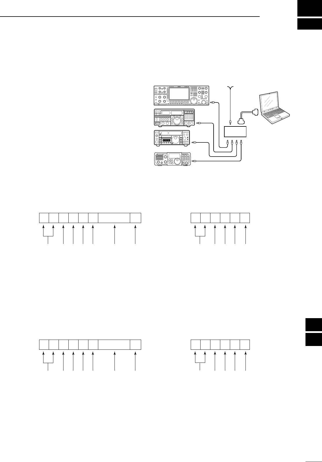
14
88
CONTROL COMMAND
1
2
3
4
5
6
7
8
9
10
11
12
13
14
15
16
17
18
19
20
21
N Remote jack (CI-V) information
D CI-V connection example
The transceiver can be connected through an optional
CT-17 CI-V LEVEL CONVERTER to a personal computer
equipped with an RS-232C port. The Icom Communi-
cation interface-V (CI-V) controls the following func-
tions of the transceiver.
Up to four Icom CI-V transceivers or receivers can be
connected to a personal computer equipped with an
RS-232C port. See pgs. 81, 82 for setting the CI-V
condition using set mode.
D Data format
The CI-V system can be operated using the following
data formats. Data formats differ according to com-
mand numbers. A data area is added for some com-
mands.
9–15 V DC
PC
ct-17
IC-7200
CONTROLLER TO IC-7200
FE
FE
FE 76 E0 Cn Sc Data area FD
Preamble code (fixed)
Transceiver’s default address
Controller’s default address
Command number
(see table at right)
Sub command number
(see table at right)
BCD code data for frequency or
memory number entry
End of message code (fixed)
OK MESSAGE TO CONTROLLER
FE FE E0 76 FB FD
Preamble code (fixed)
Controller’s default address
Transceiver’s default address
OK code (fixed)
End of message code (fixed)
NG MESSAGE TO CONTROLLER
FE FE E0 76 FA FD
Preamble code (fixed)
Controller’s default address
Transceiver’s default address
NG code (fixed)
End of message code (fixed)
IC-7200 TO CONTROLLER
FE E0 76 Cn Sc Data area FD
Preamble code (fixed)
Controller’s default address
Transceiver’s default address
Command number
(see table at right)
Sub command number
(see table at right)
BCD code data for frequency or
memory number entry
End of message code (fixed)
qwert y u
qwert y u

D Command table
Command Sub command Description
00 — Send frequency data.
(for transceive operation)
01 00 Select LSB mode
(for transceive operation)
01 Select USB mode
(for transceive operation)
02 Select AM mode
(for transceive operation)
03 Select CW mode
(for transceive operation)
04 Select RTTY mode
(for transceive operation)
07 Select CW-R mode
(for transceive operation)
08 Select RTTY-R mode
(for transceive operation)
02 — Read band edge frequencies
03 — Read operating frequency
04 — Read operating mode
05 — Set operating frequency
06 00 Select LSB mode
01 Select USB mode
02 Select AM mode
03 Select CW mode
04 Select RTTY mode
07 Select CW-R mode
08 Select RTTY-R mode
07 — Select VFO mode
00 Select VFO A
01 Select VFO B
A0 Equalize VFO A and VFO B
B0 Exchange VFO A and VFO B
08 — Select memory mode
0001−0201*
Select memory channel
*P1=0200, P2=0201
09 — Memory write
0A — Memory to VFO
0B — Memory clear
0E 00 Scan stop
01 Programmed/memory scan start
02 Programmed scan start
22 Memory scan start
D0 Set scan resume OFF
D3 Set scan resume ON
0F 00 Turn the split function OFF
01 Turn the split function ON
10 00 Select 10 Hz (or 1 Hz) tuning step
01 Select 100 Hz tuning step
02 Select 1 kHz tuning step
03 Select 5 kHz tuning step
04 Select 9 kHz tuning step
05 Select 10 kHz tuning step
11 — Set/read attenuator.
( 0=OFF, 20=ON (20 dB))
13 00 Announce with voice synthesizer
01 ( 00=all data 01=frequency and
02 S-meter; 02=receive mode)
Command Sub command Description
14 01 [AF] level setting
(0=max. CCW to 255=max. CW)
02 [RF] level setting
(0=max. CCW to 255=11 o'clock)
03 [SQL] level setting
(0=11 o'clock to 255=max. CW)
06 NR level setting
(0=0% to 255=100%)
07 Inside [PBT] setting (0= max. CCW,
128=center, 255=max. CW)
08 Outside [PBT] setting (0= max.
CCW, 128=center, 255=max. CW)
09 CW Pitch setting (0=300 Hz to
255=900 Hz (5 Hz steps))
0A RF power setting
(0=minimum to 255=100%)
0B MIC gain setting
(0=0% to 255=100%)
0C Key speed level setting
(0=6 wpm to 255=60 wpm)
0D [MNF] setting (0=max. CCW,
128=center, 255=max. CW)
0E COMP level setting
(0=0 to 255=10)
0F Break-IN delay setting
(0=2.0 d to 255=13.0 d)
12 NB level setting
(0=0% to 255=100%)
16 VOX gain setting
(0=0% to 255=100%)
17 Anti VOX gain setting
(0=0% to 255=100%)
15 01 Read squelch condition
02 Read S-meter level
11 Read RF power meter
12 Read SWR meter
13 Read ALC meter
16 02 Preamp (0=OFF, 1=ON)
12 AGC selection
(0=OFF, 1=Fast, 2=Slow.)
22 Noise blanker (0=OFF, 1=ON)
40 Noise reduction (0=OFF, 1=ON)
41 Auto notch (0=OFF, 1=ON)
44 Speech compressor
(0=OFF, 1=ON)
46 VOX function (0=OFF, 1=ON)
47 Break-IN function (0=OFF, 1=semi
BK-IN, 2=full BK-IN)
48 Manual notch (0=OFF, 1=ON)
4F Twin peak filter (0=OFF, 1=ON)
50 Dial lock function (0=OFF, 1=ON)
19 00 Read the transceiver ID
1A 00 Set/read memory contents
An additional code, 0001−0201
(0200=P1, 0201=P2), must be added
to specify the memory channel.
01 Set/read band stacking register
contents (see p. 24 for details)
02 Set/read the selected filter width
( SSB, CW, RTTY: 0=50 Hz
to 40/31=3600/2700 Hz;
AM: 0=200 Hz to 39=8 kHz)
0301 Set/read RF power setting
(0=minimum to 255=100%)
0302 Set/read MIC gain setting
(0=0% to 255=100%)
89
14 CONTROL COMMAND

90
14
CONTROL COMMAND
1
2
3
4
5
6
7
8
9
10
11
12
13
14
15
16
17
18
19
20
21
Command Sub command Description
1A 0303 Set/read Key speed level setting
(0=6 wpm to 255=60 wpm)
0304 Set/read CW Pitch setting (0=300
Hz to 120=900 Hz; 5 Hz steps)
0305 Set/read CW side tone setting
(0=0% to 255=100%)
0306 Set/read CW side tone level limit
(0=OFF, 1=ON)
0307 Set/read Twin peak filter
(0=OFF, 1=ON)
0308 Set/read RTTY mark frequency
(0=1275 Hz, 1=1615 Hz, 2=2125 Hz)
0309 Set/read RTTY shift width
( 0=170 Hz, 1=200 Hz, 2=425 Hz,
3=850 Hz)
0310 Set/read RTTY keying polarity
(0=Normal, 1=Reverse)
0311 Set/read LCD brightness
(0=OFF, 1=Dark, 2=Bright)
0312 Set/read confirmation beep
(0=OFF, 1=ON)
0313 Set/read band edge beep
(0=OFF, 1=ON)
0314 Set/read beep gain
(0=0% to 255=100%)
0315 Set/read beep gain limit
(0=OFF, 1=ON)
0316 Set/read [RF/SQL] control set
(0=Auto, 1=SQL, 2=RF+SQL)
0317 Set/read meter peak hold
(0=OFF, 1=ON)
0318 Set/read quick split set
(0=OFF, 1=ON)
0319 Set/read split lock set
(0=OFF, 1=ON)
0320 Set/read transmit frequency monitor
with [RIT] key set
(0=OFF, 1=ON)
0321 Set/read tuner auto start set
(0=OFF, 1=ON)
0322 Set/read PTT tune set (0=OFF,
1=ON)
0323 Set/read MOD input connector
during DATA OFF
( 0=MIC, 1=ACC, 2=MIC+ACC,
3=USB)
0324 Set/read MOD input connector
during DATA ON
( 0=MIC, 1=ACC, 2=MIC+ACC,
3=USB)
0325 Set/read MOD input gain from USB
(0=0% to 255=100%)
0326 Set/read speech level
(0=0% to 255=100%)
0327 Set/read speech language
(0=English, 1=Japanese)
0328 Set/read speech speed
(0=Slow, 1=Fast)
0329 Set/read S-level speech
(0=OFF, 1=ON)
0330 Set/read speech capability with
[MODE] key operation
(0=OFF, 1=ON)
0331 Set/read scan speed set
(0=Slow, 1=Fast)
0332 Set/read scan resume set
(0=OFF, 1=ON)
Command Sub command Description
1A 0333 Set/read main dial auto TS (0=OFF,
1=Low, 2=High)
0334 Set/read 1/4 dial speed set (0=OFF,
1=ON)
0335 Set/read mic. UP/DOWN speed
(0=Low, 1=High)
0336 Set/read SSB/CW synchronous
tuning function (0=OFF, 1=ON)
0337 Set/read CW carrier point set
(0=LSB, 1=USB)
0338 Set/read break-in set (0=OFF,
1=semi BK-IN, 2=full BK-IN)
0339 Set/read break-in delay time set
(20=2.0 d to 130=13.0 d)
0340 Set/read CW keyer dot/dash ratio
(28=1:1:2.8 to 45=1:1:4.5)
0341 Set/read CW paddle polarity
(0=Normal, 1=Reverse)
0342 Set/read CW keyer type
( 0=Straight, 1=Bug-key, 2=ELEC
Key)
0343 Set/read MIC UP/DOWN keyer
(HM-36) set (0=OFF, 1=ON)
0344 Set/read SSB mode selectability
( 0=OFF: inhibition, 1=ON:
selectable)
0345 Set/read CW mode selectability
( 0=OFF: inhibition, 1=ON:
selectable)
0346 Set/read RTTY mode selectability
( 0=OFF: inhibition, 1=ON:
selectable)
0347 Set/read AM mode selectability
( 0=OFF: inhibition, 1=ON:
selectable)
0348 Set/read CI-V transceive set
(0=OFF, 1=ON)
0349 Set/read reference frequency set
(0=0% to 255=100%)
0350 Set/read noise blanker level set
(0=0% to 255=100%)
0351 Set/read noise blanker width set
(0=0% to 255=100%)
0352 Set/read NR level set
(0=0 to 15=15)
0353 Set/read VOX gain set
(0=0% to 255=100%)
0354 Set/read Anti-VOX gain set
(0=0%, 255=100%)
0355 Set/read VOX delay set
(0=0.0 sec. to 20=2.0 sec.)
0356 Set/read speech compressor level
(0=0 to 10=10)
04 Set/read DATA mode set
(0=DATA OFF, 1=DATA ON)
05 Set/read DSP filter shape
(0=Sharp, 1=Soft)
06 Set/read manual notch width
(0=Wide, 1=Mid., 2=Nar.)
1C 00 Set/read the transceiver's condition
(0=Rx, 1=Tx)
01 Set/read antenna tuner condition
( 0=OFF, 1=ON, 2=Start tuning or
while tuning)

N General
• Frequency coverage :
Receive
30 kHz–60.000000 MHz*1*2
Transmit
1.800–1.999999 MHz*2, 3.500– 3.999999 MHz*2
5.33050*3, 5.34650*3, 5.36650*3,
5.37150*3, 5.40350*3,
7.000–7.300 MHz*2, 10.100 –10.150 MHz,
14.000–14.350 MHz, 18.068–18.168 MHz,
21.000– 21.450 MHz, 24.890–24.990 MHz,
28.000– 29.700 MHz, 50.000–54.000 MHz*2,
*
1Some frequency bands are not guaranteed.
*
2Depending on version. *3USA version only.
• Mode : SSB, CW, RTTY, AM
•
Number of memory CH
: 201 (split memory: 199; scan edges: 2)
channels
• Antenna connector : SO-239
• Antenna impedance : 50 ø (unbalanced)
• Usable temperature : –10°C to +60°C (+14°F to +140°F)
range
• Frequency stability : Less than ± 0.5 ppm
• Power supply : 13.8 V DC±15% (negative ground)
requirement
• Current drain : Transmit (at 100 W) 22 A
(at 13.8 V DC) Receive squelched 1.3 A
max. audio 2.0 A
• Dimensions : 241(W)
× 84(H) × 281(D) mm,
(projections not included) 91⁄2(W) × 35⁄16(H) × 111⁄16(D) in
• Weight (approx.) : 5.5 kg (12.1 lb)
• CI-V connector : 2-conductor 3.5 (d) mm (1⁄8˝)
• ACC connector : 13-pin
N Transmitter
• Output power
SSB, CW, RTTY : 2–100 W
AM : 1–25 W
• Modulation system
SSB : Digital PSN modulation
AM : Digital Low power modulation
• Spurious emissions
HF bands : Less than –50 dB
50 MHz band : Less than – 63 dB
• Carrier suppression : More than 50 dB
• Unwanted sideband : More than 50 dB
• Microphone : 8-pin connector (600 ø)
connector
• KEY connector : 3-conductor 6.3 (d) mm (1⁄4˝)
N Receiver
• Receive system : Triple-conversion
superheterodyne
• Intermediate frequencies
1st : 64.455 MHz
2nd : 455 kHz
3rd : 15.625 kHz
• Sensitivity (10dB S/N, preamp: ON, Filter shape: sharp)
SSB, CW : Less than 0.16 μV
(1.8−29.7 MHz)
Less than 0.13 μV
(50 MHz band)
AM : Less than 13 μV
(0.5−1.799 MHz)
Less than 2 μV
(1.8−29.7 MHz)
Less than 1 μV
(50 MHz band)
• Squelch sensitivity (SSB, threshold, preamp ON)
: Less than 5.6 μV
• Selectivity
SSB* (BW=2.4 kHz) : More than 2.4 kHz/–6 dB
Less than 3.6 kHz/–60 dB
CW* (BW=500 Hz) : More than 500 Hz/–6 dB
Less than 900 Hz/–60 dB
RTTY (BW=350 Hz) : More than 360 Hz/–6 dB
Less than 650 Hz/–60 dB
AM (BW=6 kHz) : More than 6.0 kHz/–6 dB
Less than 15.0 kHz/–60 dB
*IF filter shape is set to SHARP.
• Spurious and image rejection ratio
: More than 70 dB
(except
1⁄2
IF through on 50 MHz band)
• Audio output power : More than 2.0 W at 10%
distortion with an 8 ø load
(at 13.8 V DC)
• RIT variable range : ±9.999 kHz
• PHONES connector :
3-conductor 6.3 (d) mm (
1
⁄
4
˝)/8 ø
• EXT SP connector : 2-conductor 3.5 (d) mm (1⁄8˝)/8 ø
15
91
SPECIFICATIONS
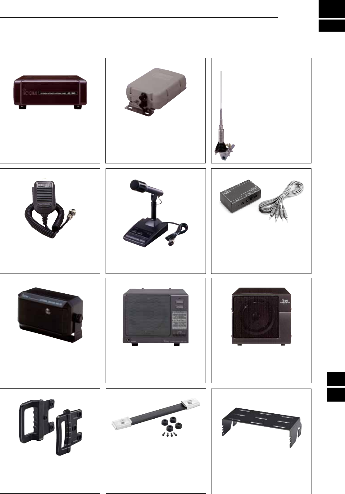
16
92
OPTIONS
1
2
3
4
5
6
7
8
9
10
11
12
13
14
15
16
17
18
19
20
21
AT-180 HF/50 MHZ AUTOMATIC
ANTENNA TUNER
Fully automatic antenna tuner with
preset memories for each 100 kHz.
Unique “automatic tuner on” func-
tion is available. See p. 68 for AT-180
specifications.
AH-4
HF
AUTOMATIC
ANTENNA
TUNER
Specially designed to tune a long wire
antenna for portable or mobile HF/50
MHz operation. The “PTT tune” func-
tion provides simple operation.
• Input power rating: 150 W
AH-2b ANTENNA ELEMENT
A 2.5 m long antenna ele-
ment for mobile operation
with the AH-4.
• Frequency coverage
7–54 MHz band with the
AH-4
SM-20 DESKTOP MICROPHONE
Includes [UP]/[DOWN] switches and a
low cut function.
CT-17 CI-V LEVEL CONVERTER UNIT
For remote transceiver control using
a personal computer equipped with
an RS-232C port. You can change
frequencies, operating mode, memory
channels, etc., via your computer.
SP-10 EXTERNAL SPEAKER
External speakers suitable for mobile
operation.
SP-10: Compact-type; 4 ø/5 W
SP-21 EXTERNAL SPEAKER
Designed for base station operation.
• Input impedance: 8 ø
• Max. input power: 5 W
HM-36 HAND MICROPHONE
Hand microphone equipped with [UP]/
[DOWN] switches.
SP-20 EXTERNAL SPEAKER
4 audio filters; headphone jack; can
connect to 2 transceivers.
• Input impedance: 8 ø
• Max. input power: 5 W
MB-116 HANDLE
Convenient when moving the trans-
ceiver and provides front panel pro-
tection during transport.
MB-117 CARRYING HANDLE
Convenient when carrying the trans-
ceiver.
MB-118 MOBILE NOUNTING
BRACKET
For mounting the transceiver in a ve-
hicle.
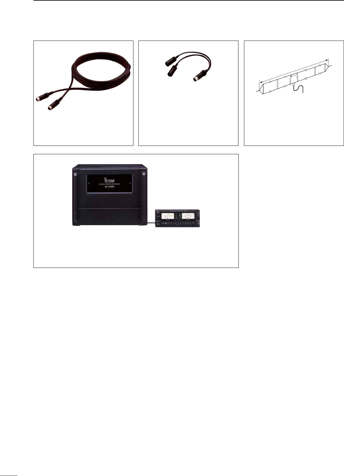
OPC-598 ACC 13-PIN CABLE
Required when using the AT-180.
• 7 m (22 ft)
OPC-599 ADAPTOR CABLE
13-pin, ACC connector to 7-pin + 8-pin
ACC connector.
IC-PW1/EURO HF/50 MHz ALL BAND 1 kW LINEAR AMPLIFIER
Full-duty 1 kW linear amplifier including an automatic antenna tuner. Has automatic tuning
and band selection capability. Full break-in (QSK) operation is possible. The amplifier/power
supply unit and the remote control unit are separated. An optional OPC-599 is required for
connection.
AH-710 FOLDED DIPOLE
ANTENNA
approx. 24.5 m; 80.3 ft
Covers from 1.9–30 MHz bands. Has an
SO-239 connector. 30 m (98.4 ft) coaxial
cable with PL-259 connector is supplied.
93
16 OPTIONS
17
94
ABOUT CE
1
2
3
4
5
6
7
8
9
10
11
12
13
14
15
16
17
18
19
20
21
INSTALLATION NOTES
For amateur base station installations it is recom-
mended that the forward clearance in front of the an-
tenna array is calculated relative to the EIRP (Effec-
tive Isotropic Radiated Power). The clearance height
below the antenna array can be determined in most
cases from the RF power at the antenna input termi-
nals.
As different exposure limits have been recommended
for different frequencies, a relative table shows a
guideline for installation considerations.
Below 30 MHz, the recommended limits are specified
in terms of V/m or A/m fields as they are likely to fall
within the near-field region. Similarly, the antennas
may be physically short in terms of electrical length
and that the installation will require some antenna
matching device which can create local, high intensity
magnetic fields. Analysis of such MF installations is
best considered in association with published guid-
ance notes such as the FCC OET Bulletin 65 Edition
97-01 and its annexes relative to amateur transmitter
installations.
The EC recommended limits are almost identical to
the FCC specified ‘uncontrolled’ limits and tables exist
that show pre-calculated safe distances for different
antenna types for different frequency bands. Further
information can be found at http://www.arrl.org/.
• Typical amateur radio installation
Exposure distance assumes that the predominant ra-
diation pattern is forward and that radiation vertically
downwards is at unity gain (sidelobe suppression is
equal to main lobe gain). This is true of almost every
gain antenna today. Exposed persons are assumed
to be beneath the antenna array and have a typical
height of 1.8 m.
The figures assume the worst case emission of a
constant carrier.
For the bands 10 MHz and higher the following power
density limits have been recommended:
10–50 MHz 2 W/sq m
Vertical clearance by EIRP output
1 Watts 2.1 m
10 Watts 2.8 m
25 Watts 3.4 m
100 Watts 5 m
1000 Watts 12 m
Forward clearance by EIRP output
100 Watts 2 m
1000 Watts 6.5 m
10,000 Watts 20 m
100,000 Watts 65 m
In all cases any possible risk depends on the trans-
mitter being activated for long periods. (actual recom-
mendation limits are specified as an average during 6
minutes) Normally the transmitter is not active for long
periods of time. Some radio licenses will require that a
timer circuit automatically cuts off the transmitter after
1–2 minutes etc.
Similarly some modes of transmission, SSB, CW, AM
etc. have a lower ‘average’ output power and the as-
sessed risk is even lower.
Versions of the IC-7200 which display the
“CE” symbol on the serial number seal,
comply with the essential requirements of
the European Radio and Telecommunica-
tion Terminal Directive 1999/5/EC.
This warning symbol indicates that this
equipment operates in non-harmonised
frequency bands and/or may be subject to
licensing conditions in the country of use.
Be sure to check that you have the correct
version of this radio or the correct pro-
gramming of this radio, to comply with na-
tional licensing requirement.
• List of Country codes (ISO 3166-1)
Country CodesCountry Codes
1
2
3
4
5
6
7
8
9
10
11
12
13
14
15
16
17
Austria
Belgium
Bulgaria
Croatia
Czech Republic
Cyprus
Denmark
Estonia
Finland
France
Germany
Greece
Hungary
Iceland
Ireland
Italy
Latvia
AT
BE
BG
HR
CZ
CY
DK
EE
FI
FR
DE
GR
HU
IS
IE
IT
LV
18
19
20
21
22
23
24
25
26
27
28
29
30
31
32
33
Liechtenstein
Lithuania
Luxembourg
Malta
Netherlands
Norway
Poland
Portugal
Romania
Slovakia
Slovenia
Spain
Sweden
Switzerland
Turkey
United Kingdom
LI
LT
LU
MT
NL
NO
PL
PT
RO
SK
SI
ES
SE
CH
TR
GB
DECLARATION
OF CONFORMITY
We Icom Inc. Japan
1-1-32, Kamiminami, Hirano-ku
Osaka 547-0003, Japan
Kind of equipment:
HF/50 MHz TRANSCEIVER
Type-designation: iC-
7200
Signature
Authorized representative name
Place and date of issue
Declare on our sole responsibility that this equipment complies with the
essential requirements of the Radio and Telecommunications Terminal
Equipment Directive, 1999/5/EC, and that any applicable Essential Test
Suite measurements have been performed.
Version (where applicable):
This compliance is based on conformity with the following harmonised
standards, specifications or documents:
i)
ii)
iii)
iv)
Düsseldorf
30th
Jun.
2008
Y. Furukawa
General Manager
EN 301 489-1 v1.6.1 (September 2005)
EN 301 489-15 v1.2.1 (August 2002)
EN 301 783-2 v1.1.1 (September 2000)
EN 60950-1 : 2001
• Version and frequency coverage
Europe (#03)
Receive
0.500– 29.999999 MHz
50.000– 54.000000 MHz
Transmit
1.810– 1.999999 MHz
3.500– 3.800000 MHz
7.000– 7.100000 MHz
10.100– 10.150000 MHz
14.000– 14.350000 MHz
18.068– 18.168000 MHz
21.000– 21.450000 MHz
24.890– 24.990000 MHz
28.000– 29.700000 MHz
50.000– 52.000000 MHz
Italy (#05)
Receive
1.830– 1.850000 MHz
3.500– 3.800000 MHz
7.000– 7.100000 MHz
10.100– 10.150000 MHz
14.000– 14.350000 MHz
18.068– 18.168000 MHz
21.000– 21.450000 MHz
24.890– 24.990000 MHz
28.000– 29.700000 MHz
50.000– 51.000000 MHz
Transmit
1.830– 1.850000 MHz
3.500– 3.800000 MHz
7.000– 7.100000 MHz
10.100– 10.150000 MHz
14.000– 14.350000 MHz
18.068– 18.168000 MHz
21.000– 21.450000 MHz
24.890– 24.990000 MHz
28.000– 29.700000 MHz
50.000– 51.000000 MHz
Spain (#06)
Receive
0.500– 29.999999 MHz
50.000– 54.000000 MHz
Transmit
1.830– 1.850000 MHz
3.500– 3.800000 MHz
7.000– 7.200000 MHz
10.100– 10.150000 MHz
14.000– 14.350000 MHz
18.068– 18.168000 MHz
21.000– 21.450000 MHz
24.890– 24.990000 MHz
28.000– 29.700000 MHz
50.000– 50.200000 MHz
Europe-1 (#07)
Receive
0.500– 29.999999 MHz
50.000– 54.000000 MHz
Transmit
1.810– 1.999999 MHz
3.500– 3.800000 MHz
7.000– 7.200000 MHz
10.100– 10.150000 MHz
14.000– 14.350000 MHz
18.068– 18.168000 MHz
21.000– 21.450000 MHz
24.890– 24.990000 MHz
28.000– 29.700000 MHz
50.000– 52.000000 MHz
France (#04)
Receive
0.500– 29.999999 MHz
50.000– 54.000000 MHz
Transmit
1.810– 1.850000 MHz
3.500– 3.800000 MHz
7.000– 7.100000 MHz
10.100– 10.150000 MHz
14.000– 14.350000 MHz
18.068– 18.168000 MHz
21.000– 21.450000 MHz
24.890– 24.990000 MHz
28.000– 29.700000 MHz
50.200– 51.200000 MHz
95
17 ABOUT CE

96
MEMO
1
2
3
4
5
6
7
8
9
10
11
12
13
14
15
16
17
18
19
20
21
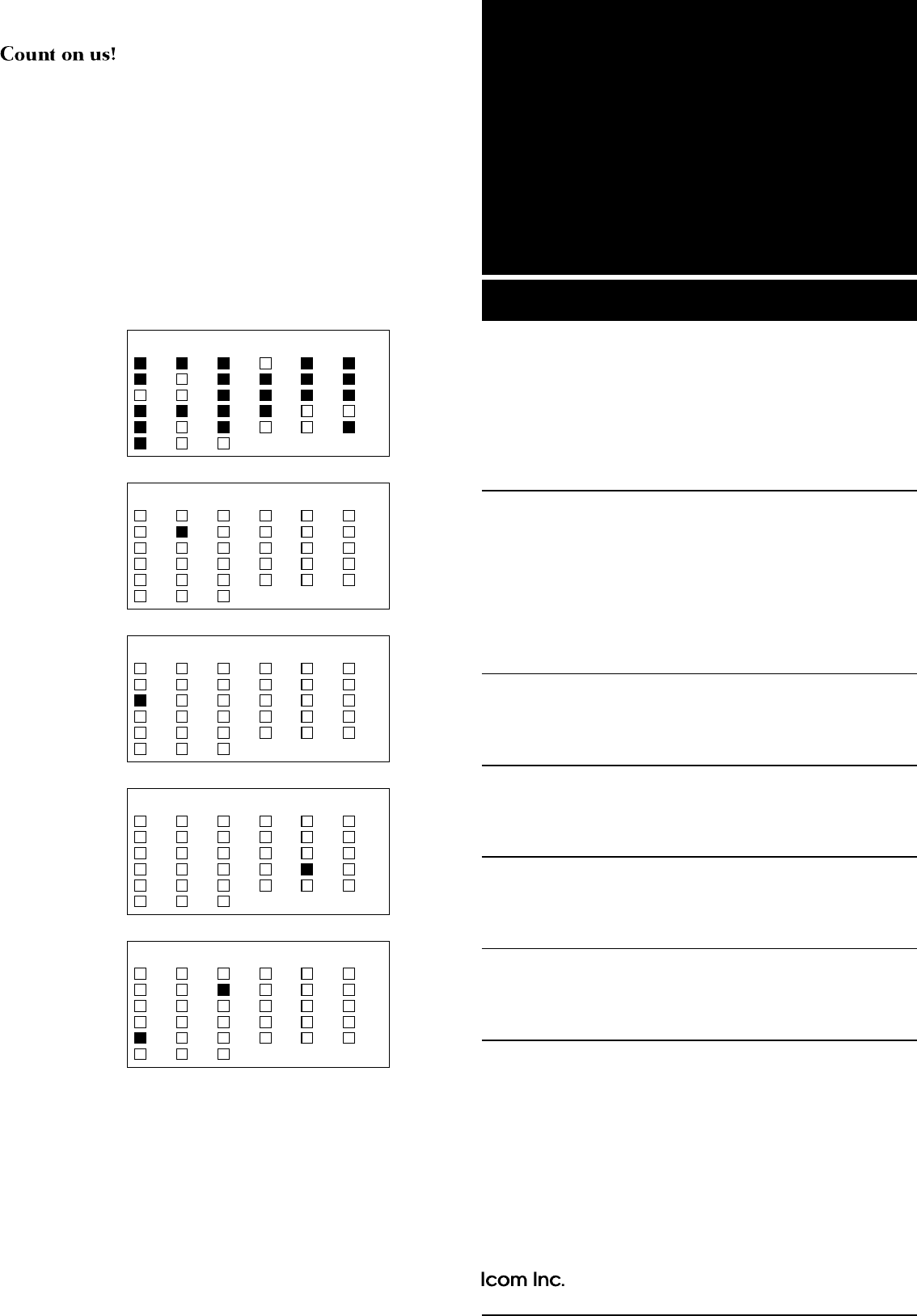
1-1-32 Kamiminami, Hirano-ku, Osaka 547-0003, Japan
A-6668D-1EX
Printed in Japan
© 2008 Icom Inc.
Printed on recycle paper with soy ink.
< Intended Country of Use >
AT
FI
IT
PL
GB
RO
BE
FR
LV
PT
IS
TR
CY
DE
LT
SK
LI
HR
CZ
GR
LU
SI
NO
DK
HU
MT
ES
CH
EE
IE
NL
SE
BG
< Intended Country of Use >
AT
FI
IT
PL
GB
RO
BE
FR
LV
PT
IS
TR
CY
DE
LT
SK
LI
HR
CZ
GR
LU
SI
NO
DK
HU
MT
ES
CH
EE
IE
NL
SE
BG
< Intended Country of Use >
AT
FI
IT
PL
GB
RO
BE
FR
LV
PT
IS
TR
CY
DE
LT
SK
LI
HR
CZ
GR
LU
SI
NO
DK
HU
MT
ES
CH
EE
IE
NL
SE
BG
< Intended Country of Use >
AT
FI
IT
PL
GB
RO
BE
FR
LV
PT
IS
TR
CY
DE
LT
SK
LI
HR
CZ
GR
LU
SI
NO
DK
HU
MT
ES
CH
EE
IE
NL
SE
BG
IC-7200 #07
(Europe-1)
< Intended Country of Use >
AT
FI
IT
PL
GB
RO
BE
FR
LV
PT
IS
TR
CY
DE
LT
SK
LI
HR
CZ
GR
LU
SI
NO
DK
HU
MT
ES
CH
EE
IE
NL
SE
BG
IC-7200 #03
(Europe)
IC-7200 #04
(France)
IC-7200 #05
(Italy)
IC-7200 #06
(Spain)