ICOM orporated 305400 VHF Marine Transceiver User Manual
ICOM Incorporated VHF Marine Transceiver
UserManual.wiki
>
ICOM orporated
>
305400 User Manual
User Manual
Navigation menu
Upload a User Manual
Namespaces
Wiki Guide
HTML
PDF
Info
Views
User Manual
Discussion / Help
Navigation
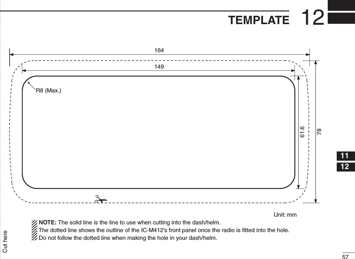
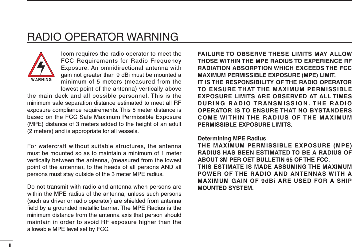
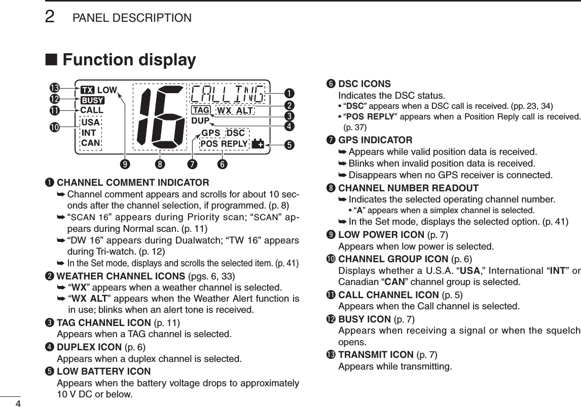
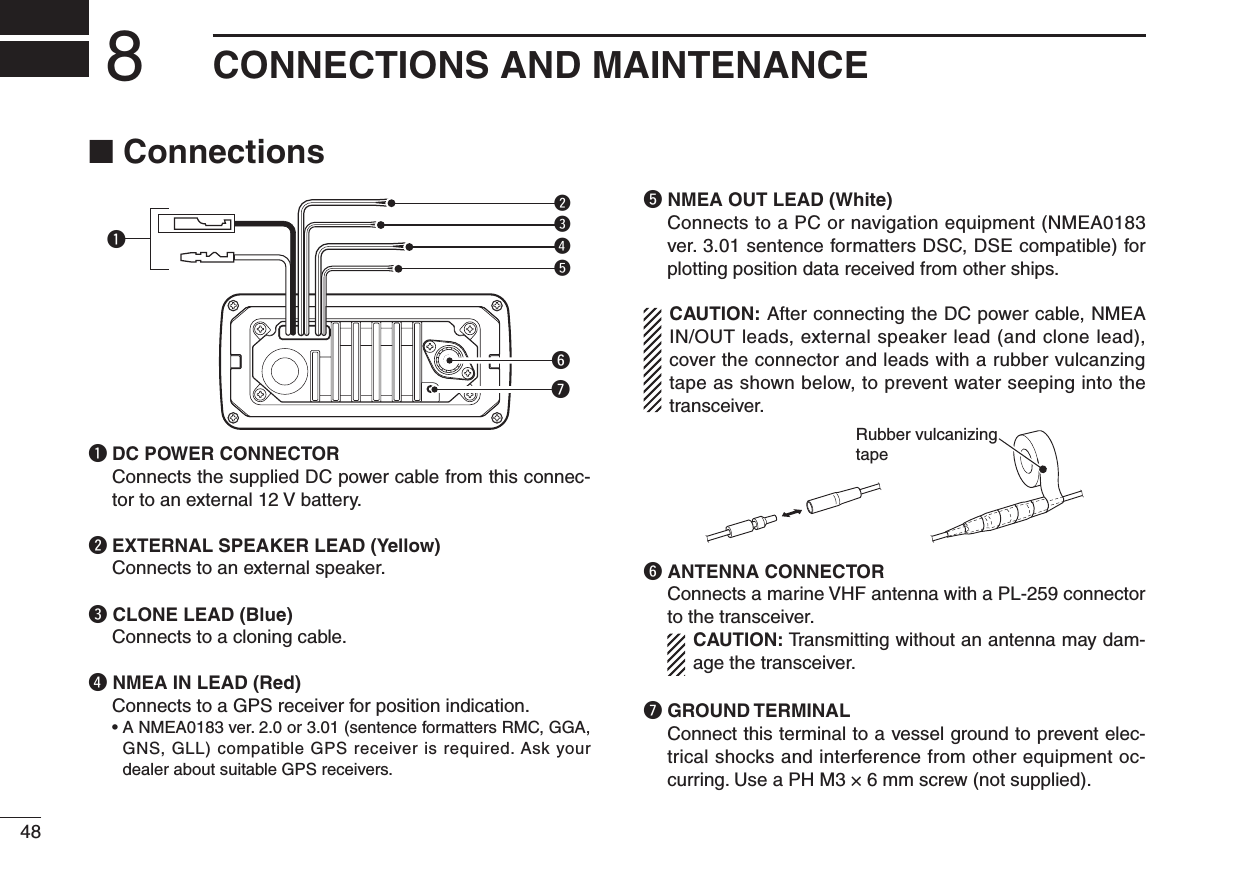
![iiNew2001IN CASE OF EMERGENCYIf your vessel requires assistance, contact other vessels and the Coast Guard by sending a Distress call on Channel 16.USING CHANNEL 16DISTRESS CALL PROCEDURE1. “MAYDAY MAYDAY MAYDAY.”2. “THIS IS ...............” (name of vessel)3. Your call sign or other indication of the vessel (AND 9-digit DSC ID if you have one).4. “LOCATED AT ...............” (your position)5. The nature of the distress and assistance required.6. Any other information which might facilitate the rescue.Or, transmit your Distress call using digital selective calling on Channel 70.USING DIGITAL SELECTIVE CALLING (Ch 70)DISTRESS CALL PROCEDURE1. While lifting up the key cover, hold down [DISTRESS] for 5 seconds until you hear 5 short beeps change to one long beep.2. Wait for an acknowledgment on Channel 70 from a coast station. •Aftertheacknowledgementisreceived,Channel16isautomatically selected.3. Hold down [PTT], then transmit the appropriate information as listed above.NOTEA WARNING STICKER is supplied with the transceiver.To comply with FCC regulations, this sticker must be affixed insuch a location as to be readily seen from the operating controls of the radio as in the diagram below. Make sure the chosen location is clean and dry before applying the sticker. (p. 36)EXAMPLEWARNING STICKER](https://usermanual.wiki/ICOM-orporated/305400/User-Guide-1344860-Page-3.png)
![2New2001PANEL DESCRIPTION2n Front panelFunction display (p. 4)Speaker i!0oweuytrqqPOWER•VOLUMECONTROL[VOL] ➥ Rotate to turn the transceiver power ON or OFF. ➥ Rotate to adjust the audio level.w SQUELCH CONTROL [SQL] (p. 7) Rotate to set the squelch threshold level.e DISTRESS KEY [DISTRESS] (p. 18) Hold down for 5 seconds to transmit a Distress call.r ENTER KEY [ENT] Push to set the DSC menu, a channel comment, etc.t CLEAR KEY [CLR] Push to cancel the entered function, or exits the Set mode.ySCAN•TAGCHANNELKEY [SCAN]•[TAG](SCAN) (p. 11) ➥ Push to start and stop the Normal or Priority scan. ➥ Hold down for 1 second to set or clear the displayed channel as a tag (scanned) channel. ➥ While holding down [HI/LO] on the microphone, hold down this key for 3 seconds to set or clear all tag chan-nels in the selected channel group.uCHANNELUP/DOWN•CHANNELGROUPKEYS [s]/[t]•[U/I/C] ➥ Push to select the operating channels, Set mode set-tings, DSC menu items, etc. (pp. 5, 6, 13, 41) ➥ Hold down [Y] to continuously move upward through the operating channels. ➥ Hold down [Z] to continuously move downward through the operating channels ➥ Push both keys to select one of three channel groups in sequence. (p. 6) •USA,InternationalandCanadianchannelsareselectable. ➥ While holding down [SCAN], push [Y] or [Z] to adjust the brightness of the LCD and key backlight. (p. 9) ➥ While holding down both keys, turn ON the power to activates the AquaQuake function. (p. 9) ➥ During scan operation, Checks TAG channels, changes scanning direction or resumes the scan manually. (p. 11)](https://usermanual.wiki/ICOM-orporated/305400/User-Guide-1344860-Page-8.png)
![32PANEL DESCRIPTIONNew2001iCHANNEL16/CALLCHANNELKEY[16]•[9](16) ➥ Push to select Channel 16. (p. 5) ➥ Hold down for 1 second to select Call channel. (p. 5) •“CALL” appears when Call channel is selected. ➥ When the Call channel is selected, hold down for 3 sec-onds to enter the Call channel programming mode. (p. 8) ➥ While holding down [CH/WX], push to enter the chan-nel comment programming mode. (p. 8) ➥ While in the channel comment programming mode, push to move the cursor backward. (p. 9) ➥ While holding down this key, turn ON the power to enter the Set mode. (p. 41)o CHANNEL/WEATHER CHANNEL KEY /DUALWATCH/TRI-WATCHKEY[CH/WX]•[DUAL](CH/WX) ➥ Selects and toggles the regular channel and Weather channel when pushed momentarily. (pp. 5, 6) ➥ Hold down for 1 second to start Dualwatch or Tri-watch. (p. 12) •PushtostopDualwatchorTri-watchwheneitherisactivated. ➥ While in the channel comment programming mode, push to advance the cursor. (p. 9)!0DSCMENUKEY[MENU]•[MMSI](MENU) (p. 13) ➥ Push to turn the DSC menu ON or OFF. ➥ Hold down for 1 second to display the MMSI code on the channel comment indicator. (pp. 5, 6)n MicrophoneMicrophoneqewq PTT SWITCH [PTT] Hold down to transmit; release to receive. (p. 7)w CHANNEL UP/DOWN KEYS [Y]/[Z] ➥ Push to select the operating channels, Set mode set-tings, DSC menu items, etc. (pp. 5, 6, 13, 41) ➥ During scan operation, checks TAG channels, changes scanning direction or manually resumes the scan. (p. 11)e TRANSMIT POWER KEY [HI/LO] ➥ Push to select the output power high or low. (p. 7) •Somechannelsaresettolowpoweronly. ➥ While holding down this key, turn ON the power to tog-gle the Microphone Lock function ON or OFF. (p. 9)2](https://usermanual.wiki/ICOM-orporated/305400/User-Guide-1344860-Page-9.png)
![53BASIC OPERATION23n Channel selectionï Channel 16Channel 16 is the distress and safety channel. It is used for establishing initial contact with a station and for emergency communications. Channel 16 is monitored during both Du-alwatch and Tri-watch. While standing by, you must monitor Channel 16.➥ Push [16] momentarily to select Channel 16.➥ Push [CH/WX] to return to the display before selecting Channel 16, or push [Y] or [Z] to select an operating channel.PushConvenient!When the Favorite channel function is turned ON (p. 43), [Y]/[Z] keys on the microphone select the favorite channels in the selected channel group in sequence when pushed.•ThefavoritechannelsaresetbytheTAGchannelsetting.(p.11)ï Channel 9 (Call channel)Each regular channel group has a separate leisure-use Call channel. The Call channel is monitored during Tri-watch. The Call channels can be programmed (p. 8) and are used to store your most often used channel in each channel group for quick recall.➥ Hold down [9](16) for 1 second to select the Call channel of the selected channel group. •“CALL” and Call channel number appear. •EachchannelgroupmayhaveanindependentCallchannelafter programming a Call channel. (p. 8)➥ Push [CH/WX] to return to the display before selecting Call channel, or push [Y] or [Z] to select an operating channel.Hold downfor 1 sec.](https://usermanual.wiki/ICOM-orporated/305400/User-Guide-1344860-Page-11.png)
![63BASIC OPERATIONNew2001ï U.S.A., international and Canadian channelsThe IC-M412 is pre-programmed with 57 USA, 57 interna-tional and 61 Canadian channels. These channel groups may be specified for the operating area.q Push [CH/WX] to select a regular channel. •Ifaweatherchannelappears,push[CH/WX] again.e Push [U/I/C] (both [Y] and [Z]) to change the channel group. (p. 6) •USA,InternationalandCanadianchannelgroupscanbese-lected in sequence.both ()andPush e Push [Y] or [Z] to select a channel. •“DUP” appears for duplex channels. •“ ” appears when a simplex channel is selected. ï Weather channelsThe IC-M422 has 10 weather channels. These are used for monitoring broadcasts from NOAA (National Oceanic and Atmospheric Administration.)The transceiver can detect a weather alert tone on the se-lected weather channel while receiving the channel, during standby on a regular channel or while scanning. (p. 33)q Push [CH/WX] once or twice to select a weather chan-nel. •“WX” appears when a weather channel is selected. •“WX ALT” appears when the Weather Alert function is in use. (p. 33)ScrollsAppearsScrollsAppearsWhen Weather alert is OFF.When Weather alert is ON.Push once or twicew Push [Y] or [Z] to select a channel.](https://usermanual.wiki/ICOM-orporated/305400/User-Guide-1344860-Page-12.png)
![73BASIC OPERATIONNew20013n Receiving and transmitting CAUTION: Transmitting without an antenna may dam-age the transceiver.q Rotate [VOL] to turn ON the power.w Set the audio and squelch levels. ➥Rotate [SQL] fully counterclockwise. ➥Rotate [VOL] to adjust the audio output level. ➥Rotate [SQL] clockwise until the noise disappears. While in the DSC operation, please make sure you set the squelch correctly.e Push [U/I/C] (both [Y] and [Z]) to change the channel group. (p. 6)r Push [Y] or [Z] to select a desired channel. (pp. 5, 6, 52) •Whenreceivingasignal,“ ” appears and audio is emitted from the speaker. •Furtheradjustmentof[VOL] may be necessary.t Push [HI/LO] on the microphone to select the output power if necessary. •“LOW” appears when low power is selected. •Chooselowpowerforshortrangecommunications,choosehigh power for longer distance communications. •Somechannelsareforlowpoweronly.y Hold down [PTT] to transmit, then speak into the micro-phone (*). •“ ” appears. •Channel70cannotbeusedfortransmissionotherthanDSC.u Release [PTT] to receive.IMPORTANT: To maximize the readability of your trans-mitted signal, pause a few seconds after holding down [PTT], hold the microphone 5 to 10 cm from your mouth and speak into the microphone (*) at a normal voice level.uwreMqyrtM: Microphone4 NOTE for TOT (Time-out Timer) functionThe TOT function inhibits continuous transmission over a preset time period after the transmission starts.A beep sounds 10 seconds before the TOT function acti-vates, to indicate the transmission will be shut down and “TOT” appears on the channel comment indicator. Transmis-sion is not possible for 10 seconds after this transmission shut down.](https://usermanual.wiki/ICOM-orporated/305400/User-Guide-1344860-Page-13.png)
![83BASIC OPERATIONNew2001n Call channel programmingCall channel is used to select Channel 9 (default), however, you can program the Call channel with your most often-used channels in each channel group for quick recall.q Push both [Y] and [Z] on the transceiver one or more times to select a desired channel group (U.S.A., Interna-tional or Canada) to be programmed.w Hold down [9](16) for 1 second to select the Call channel of the selected channel group. •“CALL” and Call channel num-ber appear.e Hold down [9](16) again for 3 seconds (until a long beep changes to two short beeps) to enter the Call channel programming mode. •Channelnumberstartsblink-ing.r Push [Y] or [Z] to select a desired channel.t Push [9](16) to program the displayed channel as the Call channel. •Push[CLR] to cancel. •Thechannelnumberstopsblinking.n Channel commentsThe channels can be labeled with a unique alphanumeric ID of up to 10 characters.Comment is indicated at the channel comment indicator for about 10 seconds after the channel selection, and the com-ment, more than 7 characters long, automatically scrolls.Capital letters, small letters (except f, j, k, p, s, v, x, z), 0 to 9, some symbols (= M + – . /) and space can be used. q Select a desired channel. •CancelDualwatch,Tri-watchorScaninadvance.w While holding down [CH/WX], push [16] to edit the channel comment program-ming mode. •Acursorandthefirstcharac-ter start blinking alternately.e Push [Y] or [Z] to select a desired character. •Push[CH/WX] or [16] to move the cursor forward or backward.r Repeat step e to input all characters.t Push [ENT] to input and set the comment. •Push[CLR] to cancel and exit the programming mode. •Thecursorandthecharacterstopblinking.y If desired, repeat steps q to t to program other channel comments.](https://usermanual.wiki/ICOM-orporated/305400/User-Guide-1344860-Page-14.png)
![93BASIC OPERATIONNew20013n Microphone Lock functionThe Microphone Lock function electrically locks the [Y] and [Z] keys on the supplied microphone. This prevents acci-dental channel changes and function access.➥ While holding down [HI/LO] on the microphone, turn ON the power to toggle the Microphone Lock function ON or OFF.[HI/LO][Y]/[Z]n Display backlightThe function display and keys can be backlit for better visibil-ity under low light conditions.Display backlight is also adjustable via the Set mode. (p. 43)➥ While holding down [SCAN], push [Y] or [Z] to adjust the brightness of the LCD and key backlight. •Thebacklightisadjustablein4levelsandOFF.n AquaQuake water draining functionThe IC-M412 uses a technology to clear water away from the speaker grill: AquaQuake. AquaQuake helps drain water away from the speaker housing (water that might otherwise muffle the sound coming from the speaker). The IC-M412 emits a vibrating noise when this function is being used.➥ While holding down both [Y] and [Z] on the transceiver, turn ON the power to activate the AquaQuake function. •Whilecontinuingtopush[Y] and [Z], a low beep tone sounds to drain water, regardless of the [VOL] control setting. •WhiletheAquaQuakefunctionisactivated,thetransceivernever accepts any key operations. •Release[Y] and [Z] to cancel the AquaQuake function.](https://usermanual.wiki/ICOM-orporated/305400/User-Guide-1344860-Page-15.png)
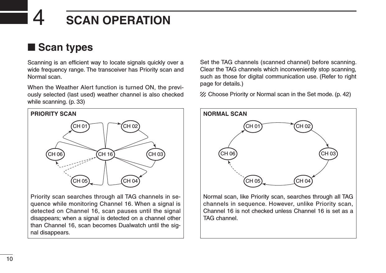
![114SCAN OPERATIONNew20014n Setting TAG channelsFor more efficient scanning, add a desired channels as TAG channels or clear the TAG for unwanted channels. Channels that are not tagged will be skipped during scan-ning. TAG channels can be independently assigned to each channel group (USA, INT, CAN).q Push [U/I/C] (both [Y] and [Z]) to select a desired chan-nel group.w Select a desired channel to be set as a TAG channel.e Hold down [TAG](SCAN) for 1 second to set the dis-played channel as a TAG channel. •“ ” appears in the display.r To cancel the TAG channel setting, repeat step e. •“ ” disappears.✓ Clearing (or setting) all tagged channelsWhile holding down [HI/LO] on the microphone, hold down [TAG](SCAN) for 3 seconds (until a long beep changes to two short beeps) to clear all TAG channels in the channel group.•RepeataboveproceduretosetallTAGchannels.n Starting a scanSet scan type (Priority or Normal scan) and scan resume timer in advance, using the Set mode. (p. 42)q Push [U/I/C] (both [Y] and [Z]) to select a desired chan-nel group.w Set TAG channels as described at left.e Make sure the squelch is closed to start a scan.r Push [SCAN] to start Priority or Normal scan. •“SCAN”blinksatthechannelcommentindicatorduringscan-ning. (During Priority scan, “16” appears beside the blinking “SCAN” indication.) •Abeeptonesoundsand“16”blinksatthechannelcommentin-dicator when a signal is received on Channel 16 during Priority scan. •Whenasignalisdetected,scanpausesuntilthesignaldisap-pears or resumes after pausing 5 seconds, depending on the Set mode setting. (Channel 16 is still monitored during Priority scan.) •Push[Y] or [Z] to check the scanning TAG channels, to change the scanning direction or resume the scan manually.t To stop the scan, push [SCAN] again.[Example]: Starting a Normal scan.Push Scan starts.When a signal isreceived.BlinksBlinksAppears](https://usermanual.wiki/ICOM-orporated/305400/User-Guide-1344860-Page-17.png)
![12New2001DUALWATCH/TRI-WATCH5n DescriptionDualwatch monitors Channel 16 while you are receiving on another channel; Tri-watch monitors Channel 16 and the Call channel while receiving another channel. Dualwatch/Tri-watch is convenient for monitoring Channel 16 when you are operating on another channel.n Operationq Select Dualwatch or Tri-watch in the Set mode. (p. 42)w Push [Y] or [Z] to select a desired channel.e Hold down [DUAL](CH/WX) for 1 second to start Dual-watch or Tri-watch. •“DW”blinksduringDualwatch;“TW”blinksduringTri-watch. •Abeeptonesoundsand“16”blinkswhenasignalisreceivedon Channel 16. r To cancel Dualwatch/Tri-watch, push [DUAL](CH/WX) again.DUALWATCH/TRI-WATCH SIMULATIONDualwatchTri-watchCall channel•IfasignalisreceivedonChannel16,Dualwatch/Tri-watch pauses on Channel 16 until the signal disappears.•IfasignalisreceivedontheCallchannelduringTri-watch, Tri-watch becomes Dualwatch until the signal dis-appears.•TotransmitontheselectedchannelduringDualwatch/Tri-watch, hold down [PTT].[Example]: Operating Tri-watch on INT Channel 25Tri-watch starts.Signal is received on Call channel.Signal is received on Channel 16 takes priority.Tri-watch resumes after the signal disappears.](https://usermanual.wiki/ICOM-orporated/305400/User-Guide-1344860-Page-18.png)
, turn ON the power to enter MMSI code programming mode.e After the display appears, release [MMSI](MENU).r Push [MENU] to enter the DSC menu.t Push [Y] or [Z] to select “MMSI” and push [ENT]. •Acursorstartsblinking.y Push [Y] or [Z] to select the specified MMSI code. •Push[CH/WX] or [16] to move the cursor forward or backward.u After programming the 9-digit MMSI code, push [ENT]. •“CONFIRMATION”scrollsatthechannelcommentindicator.Scrollsi Push [ENT], then input the same MMSI code as step y for the confirmation.o Push [ENT] to set the code. •Returnstothenormaloperation. •Push[CLR] to cancel and exit the programming mode. •Ifthedifferentcodeisinput,“INCORRECT” appears. Push [ENT] and try steps y to i again.D MMSI code checkThe 9-digit MMSI (DSC self ID) code can be checked.➥Hold down [MMSI](MENU) for 1 second to display the 9-digit MMSI (DSC self ID) code. •TheMMSIcodeisdisplayedandscrollsatthechannelcom-ment indicator. •WhennoMMSIcodeisprogrammed,“NOMMSI”appearsandwarning alarm sounds.Scrolls](https://usermanual.wiki/ICOM-orporated/305400/User-Guide-1344860-Page-19.png)
![146DSC OPERATIONNew2001n DSC address IDA total of 100 DSC address IDs (9-digit) can be programmed and named with up to 10 characters.D Programming Address IDq Push [MENU] to enter the DSC menu.w Push [Y] or [Z] to select “ADDRESS,” push [ENT].e Push [Y] or [Z] to select “ADD INDV ID,” push [ENT].Scrollsr Push [Y] or [Z] to set the 9-digit Individual ID, push [ENT]. •Push[CH/WX] or [16] to move the cursor forward or backward. •Push[CLR] to cancel and exit the programming mode.t Push [Y] or [Z] to set up to a 10-character ID name. •Push[CH/WX] or [16] to move the cursor forward or backward. •Push[CLR] to cancel and exit the programming mode.y Push [ENT] to program and returns to the normal opera-tion.](https://usermanual.wiki/ICOM-orporated/305400/User-Guide-1344860-Page-20.png)
![156DSC OPERATIONNew20016D Deleting Address IDq Push [MENU] to enter the DSC menu.w Push [Y] or [Z] to select “ADDRESS,” and push [ENT].e Push [Y] or [Z] to select “DEL INDV ID,” push [ENT]. •WhennoaddressIDisprogrammed,“NOID”isdisplayed.Scrollsr Push [Y] or [Z] to select a desired ID name for deleting and push [ENT]. •“READY”appears.t Push [ENT] to delete the selected address ID and returns to the normal operation.D Programming Group IDq Push [MENU] to enter the DSC menu.w Push [Y] or [Z] to select “ADDRESS,” push [ENT].e Push [Y] or [Z] to select “ADD GROUP ID,” push [ENT].Scrollsr Push [Y] or [Z] to set the 9-digit Group ID, push [ENT]. •Push[CH/WX] or [16] to move the cursor forward or backward. •Push[CLR] to cancel and exit the condition. 1st digit ‘0’ is fixed for a Group ID.☞ Continue to the next page](https://usermanual.wiki/ICOM-orporated/305400/User-Guide-1344860-Page-21.png)
![166DSC OPERATIONNew2001n DSC address IDD Programming Group ID (Continued)t Push [Y] or [Z] to set up to a 10-character ID name. •Push[CH/WX] or [16] to move the cursor forward or backward. •Push[CLR] to cancel and exit the programming mode.y Push [ENT] to program and returns to the normal opera-tion.D Deleting Group IDq Push [MENU] to enter the DSC menu.w Push [Y] or [Z] to select “ADDRESS,” and push [ENT].e Push [Y] or [Z] to select “DEL GROUP ID,” push [ENT]. •WhennogroupIDisprogrammed,“NOID”isdisplayed.Scrollsr Push [Y] or [Z] to select a desired ID name for deleting and push [ENT]. •“READY”appears.t Push [ENT] to delete the selected group ID and returns to the normal operation.](https://usermanual.wiki/ICOM-orporated/305400/User-Guide-1344860-Page-22.png)
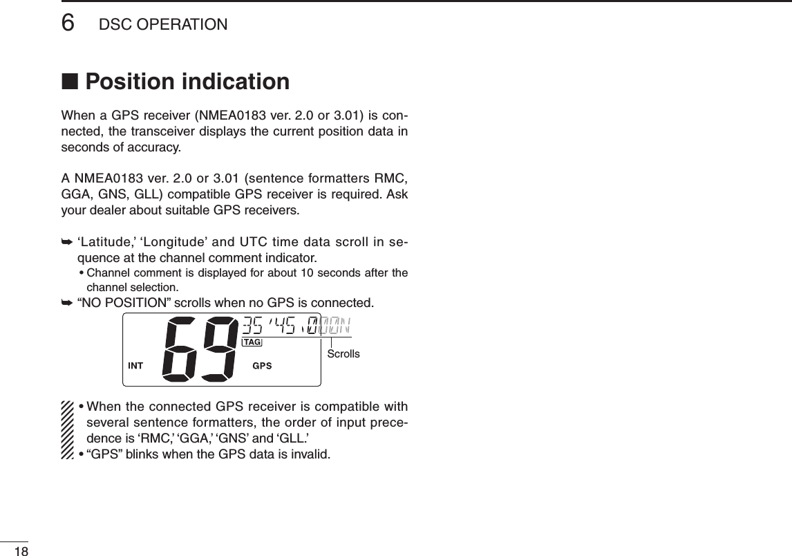
![176DSC OPERATIONNew20016A Distress call should include the ship’s position and time data. If no GPS is connected, your position and UTC (Uni-versal Time Coordinated) time should be input manually. They are included automatically when a GPS receiver (NMEA0183 ver. 2.0 or 3.01) is connected.q Push [MENU] to enter the DSC menu.w Push [s] or [t] to select “POSITION INPUT,” and push [ENT].Scrollse Push [s] or [t] to set your latitude data. After setting the latitude data, push [ENT] to set your longitude data. •Push[CH/WX] or [16] to move the cursor forward or backward. •Push[s] or [t] to edit N; North latitude or S; South latitude when the cursor is on the ‘N’ or ‘S’ position, and W; West lon-gitude or E; East longitude when the cursor is on the ‘W’ or ‘E’ position. •Push[CLR] to cancel and exit the programming mode.r After setting the longitude data, push [ENT] to set the current UTC time using [s] or [t]. •Push[CH/WX] or [16] to move the cursor forward or backward. •Push[CLR] to cancel and exit the condition.t Push [ENT] to program and returns to the normal opera-tion. Manually programmed position data will be held only for 23.5 hours. “??” may blink instead of position and time indications when the GPS data is invalid, or has not been manually updated after 4 hours.n Position and time programming](https://usermanual.wiki/ICOM-orporated/305400/User-Guide-1344860-Page-23.png)
![196DSC OPERATIONNew20016n Distress callA Distress call should be transmitted, if in the opinion of the Master, the ship or a person is in distress and requires im-mediate assistance. NEVER USE THE DISTRESS CALL WHEN YOUR SHIP OR A PERSON IS NOT IN AN EMERGENCY. A DISTRESS CALL CAN BE USED ONLY WHEN IMMEDIATE HELP IS NEEDED.D Simple callq Confirm no Distress call is being received.w While lifting up the key cover, hold down [DISTRESS] for 5 seconds to transmit the Distress call. •Emergencychannel(Ch70)isautomaticallyselectedandtheDistress call is transmitted. •Whileholddown[DISTRESS], the key backlighting is blinking.Scrollse After transmitting the Distress call, the transceiver waits for an acknowledgment call on Ch16. •TheDistresscallisautomaticallytransmittedevery3.5to4.5minutes. •“DSCREPEAT”scrollsatthechannelcommentindicator.Scrollsr After receiving the acknowledgment, reply using the mi-crophone. •“RCVDISTRESSACK”scrollsatthechannelcommentindica-tor.Scrolls➥A distress alert contains; •Kindsofdistress:Undesignateddistress •Positiondata :LatestGPSormanualinputpositiondataheld for 23.5 hrs. or until the power is turned OFF.➥ The Distress call is repeated every 3.5–4.5 min., until receiving an ‘acknowledgement.’ (‘Call repeat’ mode) •“RE-TRANSMISSION”isdisplayedwhiletransmission.➥ Push [DISTRESS] to transmit a renewed Distress call, if desired.➥Push [CLR] to transmit a the ‘Cancel ACK’ call to can-cel the ‘Call repeat’ mode. •“CANCELED”isdisplayed.](https://usermanual.wiki/ICOM-orporated/305400/User-Guide-1344860-Page-25.png)
![n Distress call (Continued)D Regular callThe nature of the Distress call should be included in the Dis-tress call.q Push [MENU] to enter the DSC menu.w Push [s] or [t] to select “DISTRESS,” and push [ENT].Scrollse Push [s] or [t] to select the nature of the distress, and push [ENT]. •‘UNDESIGNATED,’‘EXPLOSION,’‘FLOODING,’‘COLLISION,’‘GROUNDING,’ ‘CAPSIZING,’ ‘SINKING,’ ‘ADRIFT (Disable adrift),’ ‘ABANDONING (Abandoning ship),’ ‘PIRACY (Piracy at-tack),’ and ‘MOB (Man overboard)’ are available. •Theselectednatureofthedistressisstoredfor10minutes.ScrollsWhen a GPS receiver (NMEA0183 ver. 2.0 or 3.01) is connected, next steps r, t (Current position/time pro-gramming) do not appear. Go to step y.r Push [s] or [t] to set your latitude data. After setting the latitude data, push [ENT] to set your longitude data. •Push[CH/WX] or [16] to move the cursor forward or backward, respectively. •Push [s] or [t] to edit N; North latitude or S; South latitude when the cursor is on the ‘N’ or ‘S’ position, and W; West longitude or E; East longitude when the cursor is on the ‘W’ or ‘E’ position. •Push[CLR] to cancel and exit the condition.t After setting the longitude data, push [ENT] to set the cur-rent UTC time using [s] or [t], then push [ENT]. •Push[CH/WX] or [16] to move the cursor forward or backward, respectively. •Push[CLR] to cancel and exit the condition.206DSC OPERATIONNew2001](https://usermanual.wiki/ICOM-orporated/305400/User-Guide-1344860-Page-26.png)
![216DSC OPERATIONNew20016y Push [DISTRESS] for 3 seconds to transmit the Distress call. •Whilepushing[DISTRESS], the key backlighting is blinking. •Thedistressinformationisstoredfor10minutes. •Emergencychannel(Ch70)isautomaticallyselectedandtheDistress call is transmitted. •Push[CLR] to exit the condition.Scrollsu After transmitting the Distress call, the transceiver waits for an acknowledgment call on Ch 16. •TheDistresscallisautomaticallytransmittedevery3.5to4.5min.Scrollsi After receiving the acknowledgment, reply using the mi-crophone.Scrolls➥A distress alert contains (default); •Natureofdistress:Selectednatureofthedistress •Positiondata :GPS or manual input position data is held for 23.5 hrs or until the power is turned OFF.➥ The Distress call is repeated every 3.5–4.5 min., until re-ceiving an ‘acknowledgement.’ (‘Call repeat’ mode) •“RE-TRANSMISSION”isdisplayed.➥ Push [DISTRESS] to transmit a renewed Distress call, if desired.➥Push [CLR] to transmit a the ‘Cancel ACK’ call to can-cel the ‘Call repeat’ mode. •“CANCELED”isdisplayed.➥ “??” may blink instead of position and time indications when the GPS data is invalid, or has not been manu-ally updated after 4 hours.](https://usermanual.wiki/ICOM-orporated/305400/User-Guide-1344860-Page-27.png)
![226DSC OPERATIONNew2001n Transmitting DSC callsTo ensure correct operation of the DSC function, please make sure you set the squelch correctly. (p. 7)D Transmitting an Individual callThe Individual call function allows you to transmit a DSC sig-nal to a specific ship only.q Push [MENU] to enter the DSC menu.w Push [Y] or [Z] to select “INDIVIDUAL,” then push [ENT].Scrollse Push [Y] or [Z] to select a desired pre-programmed Indi-vidual address or “MANUAL INPUT,” then push [ENT]. •TheIDcodefortheindividualcanbesetinadvance.(p.14) •When“MANUALINPUT”isselected,setthe9-digitMMSIIDcode for the individual you wish to call with [Y] or [Z]. (See About Manual Inputting; p. 22.)ScrollsAbout Manual Inputting:Push [Y] or [Z] to input the 9-digit Individual ID, then push [ENT].•Push[CH/WX] or [16] to move the cursor forward or backward, respectively.•Push[CLR] to cancel and exit the condition.•Gotothenextstepafterpushing[ENT].Push/r Push [Y] or [Z] to select a desired intership channel, then push [ENT]. •Intershipchannelsarealreadypresetintothetransceiverinpreferred order. •Afterpushing[ENT], Channel 70 is automatically selected and “READY” appears at the channel comment indicator.Push](https://usermanual.wiki/ICOM-orporated/305400/User-Guide-1344860-Page-28.png)
![236DSC OPERATIONNew20016t Push [ENT] to transmit the Individual call. •IfChannel70isbusy,thetransceiverstandsbyuntilthechan-nel becomes clear. •Routinecategoryonlyisavailable.Transmittingy Stands by on the operated channel (before entering the DSC menu in step q), until an acknowledgement call is received. •“WAITINGFORACK”scrollsatthechannelcommentindicator.Scrollsu When the acknowledgement is received, “DSC” appears and “RCV ABLE ACK” or “RCV UNABLE ACK” scrolls at the channel comment indicator with beeps. •Push[CLR] to stop the beep.‘Able to comply’ is received.‘Unable to comply’ is received.ScrollsScrollsAppearsAppearsi Push [ENT] to move to the intership channel, specified in step r, then hold down [PTT] to communicate your message to the responding ship when ‘Able to comply’ is received. •Push[CLR] to return to the normal operation condition. •When‘Unabletocomply’isreceived,push[ENT] to return to the normal operation condition.ScrollsAfter receiving ‘ABLE’ ACK](https://usermanual.wiki/ICOM-orporated/305400/User-Guide-1344860-Page-29.png)
![246DSC OPERATIONNew2001n Transmitting DSC calls (Continued)D Transmitting an Individual acknowledgementWhen receiving an Individual call, you can transmit an ac-knowledgement (‘Able to comply’ or ‘Unable to comply’) by using the on screen prompts (Quick ACK.) Also, you can send an acknowledgement through the menu system (Man-ual ACK.)Quick ACK:➥ After an Individual call is received, push [CLR] to stop beep, then push [ENT]. (Go to step r as below.)Manual ACK:q Push [MENU] to enter the DSC menu.w Push [Y] or [Z] to select “INDV ACK,” the push [ENT]. •“INDV ACK” item appears after receiving an Individual call.Scrollse Push [Y] or [Z] to select a desired individual address, then push [ENT].Scrollsr Push [Y] or [Z] to select the acknowledgement “ABLE” or “UNABLE,” then push [ENT]. •“UNABLE” selection will transmit the reason “No Reason Given”. •Afterpushing[ENT], Channel 70 is automatically selected and “READY” appears at the channel comment indicator.‘ABLE’ is selected.Pusht Push [ENT] to transmit the acknowledgement call to the selected station.Transmitting](https://usermanual.wiki/ICOM-orporated/305400/User-Guide-1344860-Page-30.png)
![256DSC OPERATIONNew20016y After the Individual acknowledgement call has been trans-mitted, the specified channel (specified by the calling sta-tion) is selected automatically when “ABLE” is selected, or returns to the previous condition (before entering the DSC menu) when “UNABLE” is selected in step e.ScrollsAfter transmitting ‘ABLE’ ACKD Transmitting a Group callThe Group call function allows you to transmit a DSC signal to a specific group only.q Push [MENU] to enter the DSC menu.w Push [Y] or [Z] to select “GROUP,” then push [ENT].e Push [Y] or [Z] to select a desired pre-programmed Group address or “MANUAL INPUT,” then push [ENT]. •TheIDcodeforthegroupcanbesetinadvance.(p.15) •When“MANUALINPUT”isselected,setthe8-digitMMSIIDcode for the group you wish to call with [Y] or [Z]. (See About Manual Inputting as at right.)Scrolls☞ Continue to the next page](https://usermanual.wiki/ICOM-orporated/305400/User-Guide-1344860-Page-31.png)
![266DSC OPERATIONNew2001n Transmitting DSC calls D Transmitting a Group call (Continued)About Manual Inputting:Push [Y] or [Z] to input the 8-digit Group ID, then push [ENT].•Push[CH/WX] or [16] to move the cursor forward or backward, respectively.•Push[CLR] to cancel and exit the condition.•1stdigit‘0’isxedforaGroupID.•Gotothenextstepafterpushing[ENT].Push/r Push [Y] or [Z] to select a desired intership channel, then push [ENT]. •Intershipchannelsarealreadypresetintothetransceiverinrecommending order. •Afterpushing[ENT], Channel 70 is automatically selected and “READY” appears at the channel comment indicator.Pusht Push [ENT] to transmit the Group call. •IfChannel70isbusy,thetransceiverstandsbyuntilthechan-nel becomes clear. •Routinecategoryonlyisavailable.Transmittingy After the Group call has been transmitted, the specified channel (in step r) is automatically selected.ScrollsAfter transmitting ‘ABLE’ ACKu Hold down [PTT] to announce your message to the re-sponding ship.](https://usermanual.wiki/ICOM-orporated/305400/User-Guide-1344860-Page-32.png)
![276DSC OPERATIONNew20016D Transmitting an All Ships callLarge ships use Channel 70 as their ‘listening channel.’When you want to announce a message to these ships within range, use the ‘All Ships call’ function.q Push [MENU] to enter the DSC menu.w Push [Y] or [Z] to select “ALL SHIPS,” then push [ENT].Scrollse Push [Y] or [Z] to select the desired category, then push [ENT]. •Outputpowerof‘Routine’categoryis1W(lowpower)only. •Theselectablecategorymaydifferaccordingtothepro-grammed setting. Ask your dealer for the available categories.r Push [Y] or [Z] to select a desired ITU channel, then push [ENT]. •Afterpushing[ENT], Channel 70 is automatically selected and “READY” appears at the channel comment indicator.Pusht Push [ENT] to transmit the All Ships call.Transmittingy After the All Ships call has been transmitted, the specified channel (in step r) is selected automatically.Scrolls](https://usermanual.wiki/ICOM-orporated/305400/User-Guide-1344860-Page-33.png)
![286DSC OPERATIONNew2001n Transmitting DSC calls (Continued)D Transmitting a Position Request callTransmit a Position Request call when you want to know a specified ship’s current position, etc.q Push [MENU] to enter the DSC menu.w Push [Y] or [Z] to select “POS REQUEST,” then push [ENT].Scrollse Push [Y] or [Z] to select a desired pre-programmed Indi-vidual address or “MANUAL INPUT,” then push [ENT]. •TheIDcodefortheindividualcanbesetinadvance.(p.14) •When“MANUALINPUT”isselected,setthe9-digitMMSIIDcode for the individual you wish to call with [Y] or [Z]. (See About Manual Inputting; p. 22)Scrollsr After step e, Channel 70 is automatically selected and “READY” appears at the channel comment indicator.PushThe last digit*This illustration describes with “MANUAL INPUT” selection in step e.t Push [ENT] to transmit the Position Request call. •IfChannel70isbusy,thetransceiverstandsbyuntilthechan-nel becomes clear.Transmittingy After the Position Request call has been transmitted, re-turns to the normal operation.Scrolls](https://usermanual.wiki/ICOM-orporated/305400/User-Guide-1344860-Page-34.png)
![296DSC OPERATIONNew20016D Transmitting a Position Reply callTransmit a Position Reply call when a Position Request call is received.q Push [MENU] to enter the DSC menu.w Push [Y] or [Z] to select “POS REPLY,” then push [ENT]. •“POSREPLY”itemappearsafterreceivingaPositionRequestcall.Scrollse Push [Y] or [Z] to select a desired individual address, then push [ENT].Scrollsr The position information appears. Input your position data (latitude and longitude) directly with [Y] or [Z]. (p. 17)t After editing the position data, push [ENT] to set. Then edit the current UTC time directly with [Y] or [Z] (p. 17), then push [ENT]. •Afterpushing[ENT], Channel 70 is automatically selected and “READY” appears at the channel comment indicator.y Push [ENT] to transmit the Position Reply call.Transmittingu After the Position Reply call has been transmitted, returns to the normal operation.Scrolls](https://usermanual.wiki/ICOM-orporated/305400/User-Guide-1344860-Page-35.png)
![306DSC OPERATIONNew2001n Transmitting DSC calls (Continued)D Transmitting a Polling Request callTransmit a Polling Request call when you want to know a specific ship is in the communication area, etc. q Push [MENU] to enter the DSC menu.w Push [Y] or [Z] to select “POLL REQUEST,” then push [ENT].Scrollse Push [Y] or [Z] to select a desired pre-programmed Indi-vidual address or “MANUAL INPUT,” then push [ENT]. •TheIDcodefortheindividualcanbesetinadvance.(p.14) •When“MANUALINPUT”isselected,setthe9-digitMMSIIDcode for the individual you wish to call with [Y] or [Z]. (See About Manual Inputting; p. 22)Scrollsr After step e, Channel 70 is automatically selected and “READY” appears at the channel comment indicator.PushThe last digit*This illustration describes with “MANUAL INPUT” selection in step e.t Push [ENT] to transmit the Polling Request call. •IfChannel70isbusy,thetransceiverstandsbyuntilthechan-nel becomes clear.Transmittingy After the Polling Request call has been transmitted, re-turns to the normal operation.Scrolls](https://usermanual.wiki/ICOM-orporated/305400/User-Guide-1344860-Page-36.png)
![316DSC OPERATIONNew200112345678910111213141516D Transmitting a Polling Reply callTransmit a Polling Reply call when a Polling Request call is received.q Push [MENU] to enter the DSC menu.w Push [Y] or [Z] to select “POLL REPLY,” then push [ENT]. •“POLLREPLY”itemappearsafterreceivingaPollingRequestcall.Scrollse Push [Y] or [Z] to select a desired individual address, then push [ENT]. •Afterpushing[ENT], Channel 70 is automatically selected and “READY” appears at the channel comment indicator.ScrollsPushr Push [ENT] to transmit the Polling Reply call.Transmittingt After the Polling Reply call has been transmitted, returns to the normal operation.Scrolls](https://usermanual.wiki/ICOM-orporated/305400/User-Guide-1344860-Page-37.png)
![326DSC OPERATIONNew2001n Transmitting DSC calls (Continued)D Test CallTesting on the exclusive DSC distress and safety calling channels should be avoided as much as possible by using other methods. When testing on the distress/safety chan-nel is unavoidable, it should be indicated that these are test transmissions.Normally the test call would require no further communica-tions between the two stations involved.q Push [MENU] to enter the DSC menu.w Push [s] or [t] to select “TEST CALL,” and then push [ENT].Scrollse Push [Y] or [Z] to select a desired pre-programmed Indi-vidual address or “MANUAL INPUT,” then push [ENT]. •TheIDcodefortheindividualcanbesetinadvance.(p.14) •When“MANUALINPUT”isselected,setthe9-digitMMSIIDcode for the individual you wish to call with [Y] or [Z]. (See About Manual Inputting; p. 22)Scrollsr After step e, Channel 70 is automatically selected and “READY” appears at the channel comment indicator.PushThe last digit*This illustration describes with “MANUAL INPUT” selection in step e.r Push [ENT] to transmit the Test call. •IfChannel70isbusy,thetransceiverstandsbyuntilthechan-nel becomes clear.Transmittingt After the Test call has been transmitted, returns to the normal operation.Scrolls](https://usermanual.wiki/ICOM-orporated/305400/User-Guide-1344860-Page-38.png)
![336DSC OPERATIONNew200112345678910111213141516D Transmitting a Test Ack callTransmit a Test Acknowledgement call when a Test call is received.q Push [MENU] to enter the DSC menu.w Push [Y] or [Z] to select “TEST ACK,” then push [ENT]. •“TESTACK”itemappearsafterreceivingaPollingRequestcall.Scrollse Push [Y] or [Z] to select a desired individual address, then push [ENT]. •Afterpushing[ENT], Channel 70 is automatically selected and “READY” appears at the channel comment indicator.ScrollsPushr Push [ENT] to transmit the Test Ack call.Transmittingt After the Test Ack call has been transmitted, returns to the normal operation.Scrolls](https://usermanual.wiki/ICOM-orporated/305400/User-Guide-1344860-Page-39.png)
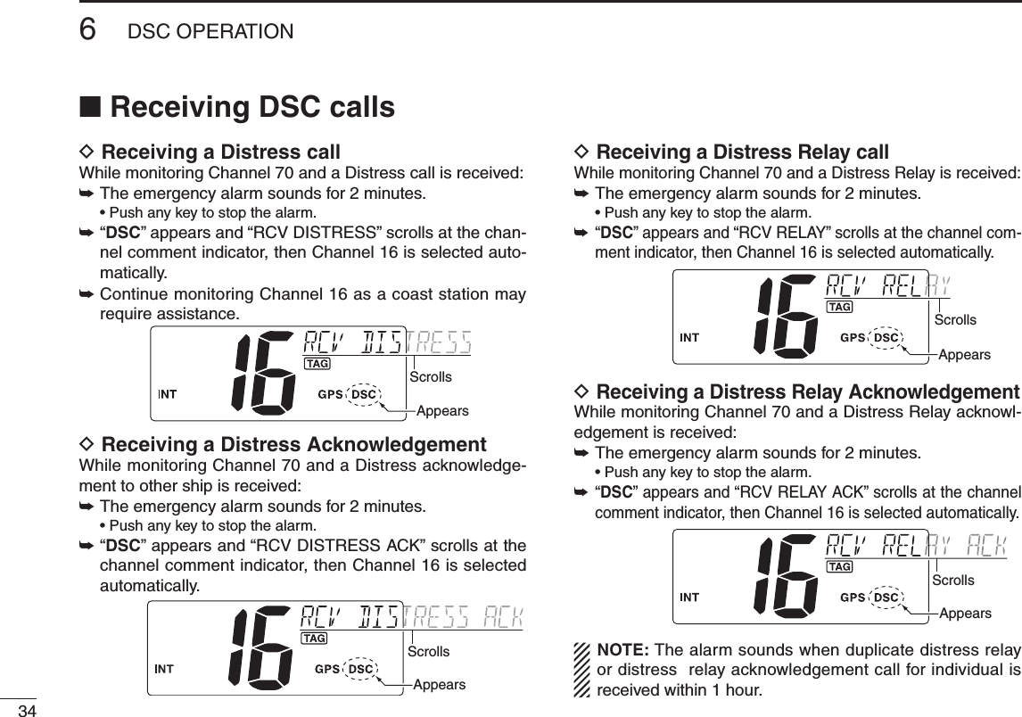
![356DSC OPERATIONNew200112345678910111213141516D Receiving an Individual callWhile monitoring Channel 70 and an Individual call is received:➥ The emergency alarm or beeps sound for 2 minutes de-pending on the received category. •Push[CLR] to stop the alarm or beeps.➥ “ DSC” appears and “RCV INDIVIDUAL” scrolls at the chan-nel comment indicator.ScrollsAppears➥ Push [ENT] to reply the call and select the channel speci-fied by the calling station for voice communication (de-pending on your replying condition. See p, 23 for Individual acknowledgement call procedure for details.); push [CLR] other key to ignore the call.D Receiving a Group callWhile monitoring Channel 70 and a Group call is received:➥ The emergency alarm or beeps sound for 2 minutes de-pending on the received category. •Push[CLR] to stop the alarm or beeps.➥ “ DSC” appears and “RCV GROUP” scrolls at the channel comment indicator.➥ Push [ENT] to select the channel specified by the calling sta-tion for voice communication; push [CLR] to ignore the call.ScrollsAppears](https://usermanual.wiki/ICOM-orporated/305400/User-Guide-1344860-Page-41.png)
![366DSC OPERATIONNew2001n Receiving DSC calls (Continued)D Receiving an All Ships callWhile monitoring Channel 70 and an All Ships call is received:➥ The emergency alarm sounds for 2 minutes depending on the received categories. •Push[CLR] to stop the alarm or beeps.➥ “ DSC” appears and “RCV ALL SHIPS” scrolls at the chan-nel comment indicator.➥ Push [ENT] to monitor Channel 16 for an announcement from the calling vessel, push [CLR] to ignore the call.ScrollsAppearsD Receiving a Geographical Area callWhile monitoring Channel 70 and a Geographical Area call (for the area you are in) is received:➥ The emergency alarm or beeps sound for 2 minutes de-pending on the received category. •Push[CLR] to stop the alarm or beeps.➥ “ DSC” appears and “RCV GEOGRAPHICAL” scrolls at the channel comment indicator.ScrollsAppears➥ Push [ENT] to select the channel specified by the calling sta-tion for voice communication; push [CLR] to ignore the call.➥ Monitor the selected channel for an announcement from the calling station. When no GPS receiver is connected or if there is a prob-lem with the connected receiver, all Geographical Area calls are received, regardless of your position.](https://usermanual.wiki/ICOM-orporated/305400/User-Guide-1344860-Page-42.png)
![376DSC OPERATIONNew200112345678910111213141516D Receiving a Position Request callWhile monitoring Channel 70 and a Position Request call is received:➥ “ DSC” appears and “RCV POS REQUEST” scrolls at the channel comment indicator.➥ The beeps sound for 2 minutes. •Push[CLR] to stop the beeps.➥Push [ENT] to reply to the call; push [CLR] to ignore the call.ScrollsAppearsD Receiving a Polling Request callWhile monitoring Channel 70 and a Polling Request call is received:➥ “ DSC” appears and “RCV POLL REQUEST” scrolls at the channel comment indicator.➥ The beeps sound for 2 minutes. •Push[CLR] to stop the beeps.➥Push [ENT] to reply to the call; push [CLR] to ignore the call.ScrollsAppearsD Receiving a Position Reply callWhile monitoring Channel 70 and a Position Request Reply call is received:➥“DSC” and “POS REPLY” appear in the display. •The‘Latitude’and‘Longitude’fromthecalledstationisdis-played and scrolled at the channel comment indicator in order of Latitude co-ordinates and then Longitude co-ordinates. •“NOPOSITION”scrollsatthechannelcommentindicatorwhenno position information is received.➥ The beeps sound for 2 minutes. •Push[CLR] to stop the beeps.ScrollsAppearsD Receiving a Polling Reply callWhile monitoring Channel 70 and a Polling Reply call is re-ceived:➥ “ DSC” appears and “RCV POLL REPLY” scrolls at the channel comment indicator.➥ The beeps sound for 2 minutes. •Push[CLR] to stop the beeps.ScrollsAppears](https://usermanual.wiki/ICOM-orporated/305400/User-Guide-1344860-Page-43.png)
![386DSC OPERATIONNew2001n Receiving DSC calls (Continued)D Receiving a Test callWhile monitoring Channel 70 and a Test call is received:➥ “ DSC” appears and “RCV TEST CALL” scrolls at the channel comment indicator.➥ The beeps sound for 2 minutes. •Push[CLR] to stop the beeps.➥Push [ENT] to reply to the call; push [CLR] to ignore the call.ScrollsAppearsD Receiving a Test Acknowledgement callWhile monitoring Channel 70 and a Test Acknowledgement call is received:➥ “ DSC” appears and “RCV TEST ACK” scrolls at the chan-nel comment indicator.➥ The beeps sound for 2 minutes. •Push[CLR] to stop the beeps.➥Push [ENT] to reply to the call; push [CLR] to ignore the call.ScrollsAppearsD Auto switch functionBy regulation, after receiving a Distress call, the transceiver basically switches the operating channel to CH 16. However, when this setting is set to “OFF,” the function enables the transceiver to remain on the operating channel even after receiving a Distress call.q Push [MENU] to enter the DSC menu.w Push [s] or [t] to select “AUTO SW,” and push [ENT].e Push [s] or [t] to select the Auto switch “ON” or “OFF.” •Push[CLR] to cancel and exit the setting.OFF : The transceiver remains on the operating channel even after receiving a Distress call.ON : The transceiver automatically switches the operating channel to CH16 after receiving a Distress call. (default)r Push [ENT] to set and exits the setting.](https://usermanual.wiki/ICOM-orporated/305400/User-Guide-1344860-Page-44.png)
![396DSC OPERATIONNew200112345678910111213141516D Auto tune timerThis is the amount of time after receiving a Distress call before the transceiver switches to CH 16.q Push [MENU] to enter the DSC menu.w Push [s] or [t] to select “AUTO TUNE,” and push [ENT].Scrollse Push [s] or [t] to set the Auto tune timer period to be-tween 10 and 600 seconds (1 second steps) or turn OFF. •Push[CLR] to cancel and exit the setting.OFF : Turns OFF the Auto Tune timer.10 to 600 : After receiving a Distress call, the transceiver remains on the operating channel for the programmed time period between 10 and 600 seconds, and then automatically switches to CH16. (default : 30) Within the programmed timer period, the following action can be taken: - When the [ENT] key is pushed, immediately switches to CH 16.| - When the [CLR] key is pushed, the Auto tune timer is cancelled and the transceiver remains on the operating channelled. r Push [ENT] to set and exits the setting.The action of the transceiver may differ, depending on the combination of the Auto Switch function and the Auto Tune timer settings.•CombinedoperationwhenreceivingaDSCcall:Auto SwitchOFF ONAutotuneOFF The transceiver remains on the operating channel.The transceiver automatically switches to CH 16.ON(10 to 600)The transceiver remains on the operating channel for the programmed time period, and then automatically switches to CH16.Within the programmed timer period, the following action can be taken:•When th e [ENT] key is pushed, immediately switches to CH 16.•When the [CLR] key is pushed, remains on the operating channel since the Auto Tuner timer is cancelled.](https://usermanual.wiki/ICOM-orporated/305400/User-Guide-1344860-Page-45.png)
![406DSC OPERATIONNew2001n Received messagesThe transceiver automatically stores up to 20 distress mes-sages and 20 other messages. The messages can be used as an assistance to the logbook.D Distress messageq Push [MENU] to enter the DSC menu.w Push [s] or [t] to select “DSC LOG,” and push [ENT].e Push [s] or [t] to select “DISTRESS,” push [ENT].Scrollsr Push [s] or [t] to select a desired message, push [ENT]. •“M” appears when the unread messages is selected.Scrollst The message information scrolls. •Thestoredmessagehasvariousinformation. •Push[CLR] to exit the condition. •Holddown[CLR] for 1 second to delete the displayed message and returns to DSC menu.ScrollsD Other messagesq Push [MENU] to enter the DSC menu.w Push [s] or [t] to select “DSC LOG,” and push [ENT].e Push [s] or [t] to select “OTHER,” push [ENT].](https://usermanual.wiki/ICOM-orporated/305400/User-Guide-1344860-Page-46.png)
![416DSC OPERATIONNew200112345678910111213141516r Push [s] or [t] to select a desired message, push [ENT]. •“M” appears when the unread messages is selected.Scrollst The message information scrolls. •Thestoredmessagehasvariousinformation. •Push[CLR] to exit the condition. •Holddown[CLR] for 1 second to delete the displayed message and returns to DSC menu.Scrolls](https://usermanual.wiki/ICOM-orporated/305400/User-Guide-1344860-Page-47.png)
![426DSC OPERATIONNew2001n Automatic acknowledgement This item sets the automatic acknowledgement function ON or OFF.When a position request or polling request call is received, transceiver automatically transmits a position request reply or polling reply call, respectively.q Push [MENU] to enter the DSC menu.w Push [s] or [t] to select “AUTO ACK,” and push [ENT].Scrollse Push [s] or [t] to turn the automatic acknowledgement function ON or OFF.r Push [ENT] to set the condition. •Push[CLR] to cancel and exit the condition.n Offset timeThis item sets the offset time from the UTC (Universal Time Coordinated) time.q Push [MENU] to enter the DSC menu.w Push [s] or [t] to select “OFFSET TIME,” and push [ENT].Scrollse Set the offset time from the UTC (Universal Time Coordi-nated) time using [s] or [t]. •Push[CH/WX] or [16] to move the cursor forward or backward, respectively. •Push[CLR] to cancel and exit the condition.r Push [ENT] to program and to exit the condition.The local time indication is not available when the GPS receiver (sentence formatter RMC) is connected, the transceiver’s display indicates UTC time only.](https://usermanual.wiki/ICOM-orporated/305400/User-Guide-1344860-Page-48.png)

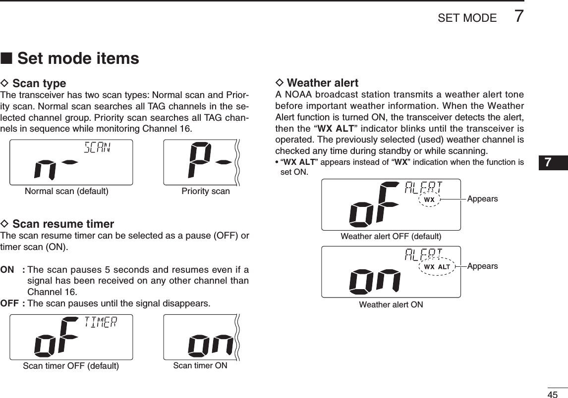
![44New2001New2001SET MODE7n Set mode programmingSet mode is used to change the conditions of the trans-ceiver’s functions: Scan type, Scan resume timer, Dual/Tri-watch, Operation beep, LCD backlight, LCD contrast, AF level adjustment and Favorite channel. Available functions may differ depending on dealer set-ting.q Turn power OFF.w While pushing [16], turn ON the power to enter the Set mode. •“SCAN”appearsatthechannelcommentindicator.e After the display appears, release [16].r Push [16] to select a desired item, if necessary.t Push [Y] or [Z] to select the desired setting of the item.y Turn power OFF, then ON again to exit the Set mode.D SET MODE CONSTRUCTION• Weather alert• Dual/Tri-watch• Scan resumetimer• Operation beep• AF leveladjustment• LCD Contrast • LCD Backlight• Remote ID• Favorite channel• Scan type, turn power ON.• To enter Set mode: While pushing• To exit Set mode: Tu rn power OFF, then ON again.• To select the item: Push . ( ) Starting itemScrollsScrollsScrollsScrolls](https://usermanual.wiki/ICOM-orporated/305400/User-Guide-1344860-Page-50.png)
![New2001467SET MODENew2001D Dual/Tri-watchThis item can be selected as Dualwatch or Tri-watch. (p. 12)Dualwatch (default) Tr i-watchD Operation beepYou can select the silent operation by turning beep tones OFF or you can have confirmation beeps sound at the push of a key by turning beep tones ON.Beep tone ON (default) Beep tone OFFD LCD backlightThe LCD backlight brightness can be adjusted from OFF, 1 (dark) to 4 (bright.)LCD backlight is also adjustable via [SCAN•TAG] key. (p. 9)•“BACKLIGHT” scrolls at the channel comment indicator.LCD backlight level 4 (default) LCD backlight OFFScrollsD LCD contrastThe LCD contrast can be adjustable in 4 levels. 1 is the low-est contrast, and 4 is the highest contrast.•“CONTRAST” scrolls at the channel comment indicator.LCD contrast level 3 (default)Scrolls](https://usermanual.wiki/ICOM-orporated/305400/User-Guide-1344860-Page-52.png)
![New2001New2001477SET MODENew200112345678910111213141516D AF level adjustmentWhen turning the power ON, a beep is emitted to adjust the audio frequency level via [VOL].Select the time period for the beep emission from 2, 5, 8, 10 (seconds) or OFF.AF level 2 (default) AF level OFFD Favorite channelThis item sets the Favorite channel function ON or OFF.The favorite channels are set by the TAG channel setting. (p. 11)•“FAVORITE” scrolls at the channel comment indicator.ON : [Y]/[Z] keys on the microphone select the favorite channels in the selected channel group in sequence when pushed.OFF : [Y]/[Z] keys on the microphone select all channels in the selected channel group in sequence when pushed.Favorite channel ON (default) Favorite channel OFFScrollsD Remote IDSet a Remote ID number between 01 and 69.The Remote ID is included in the sentence of the format for the Icom own NMEA.Remote ID 14 (default) Remote ID 69Scrolls](https://usermanual.wiki/ICOM-orporated/305400/User-Guide-1344860-Page-53.png)
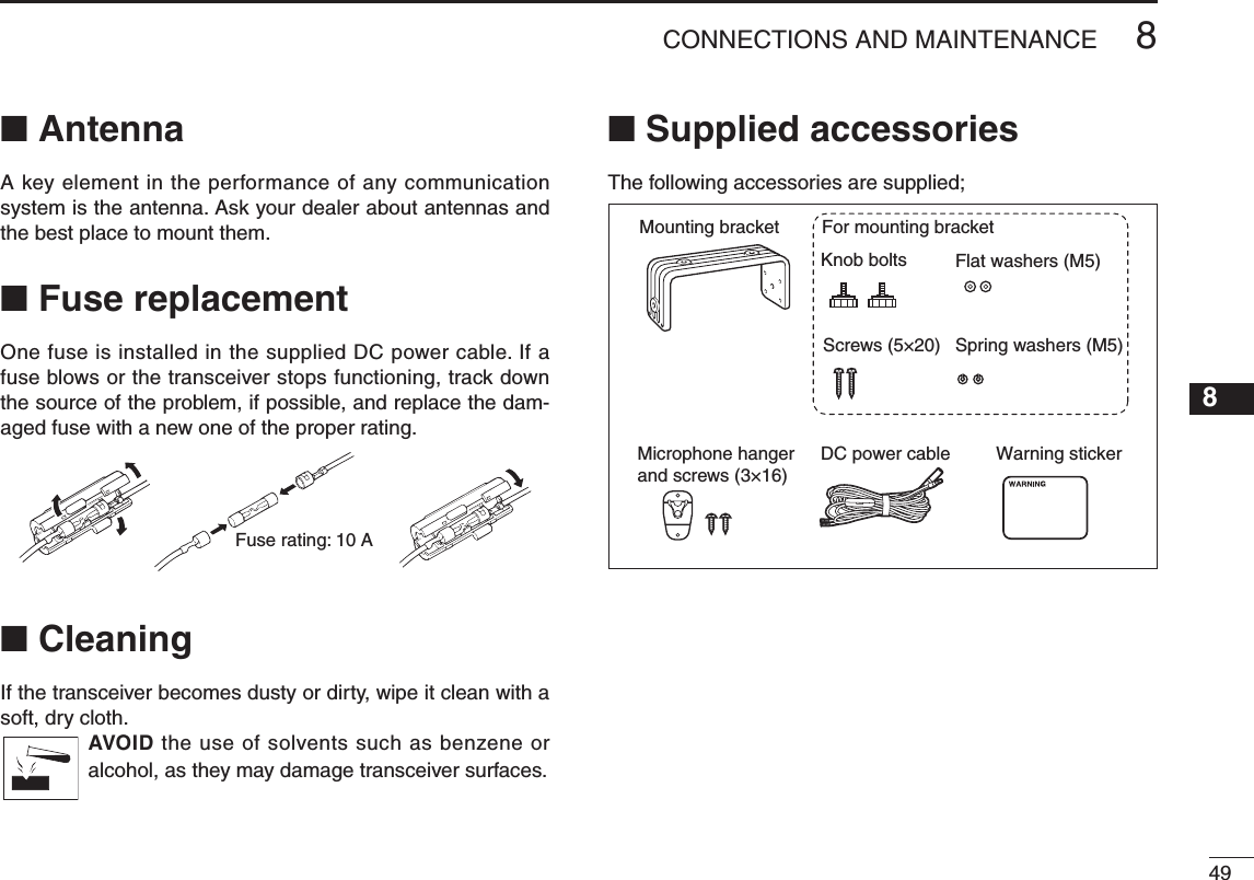
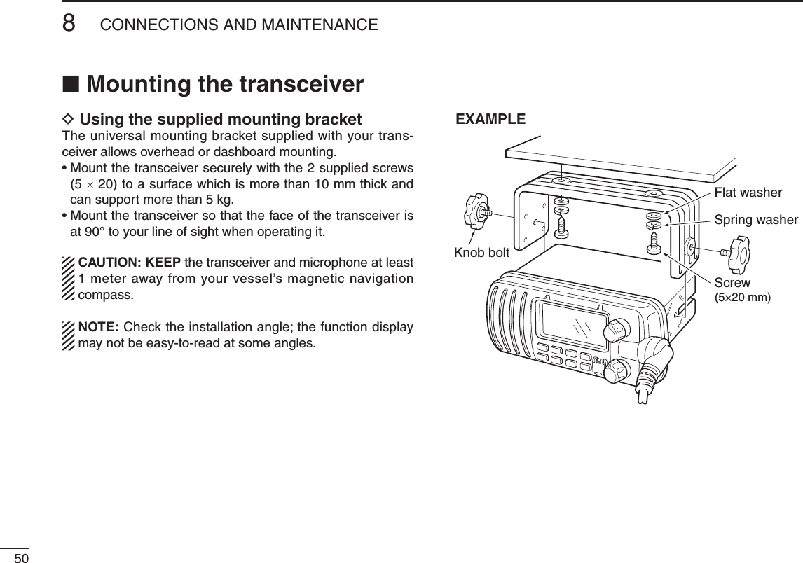
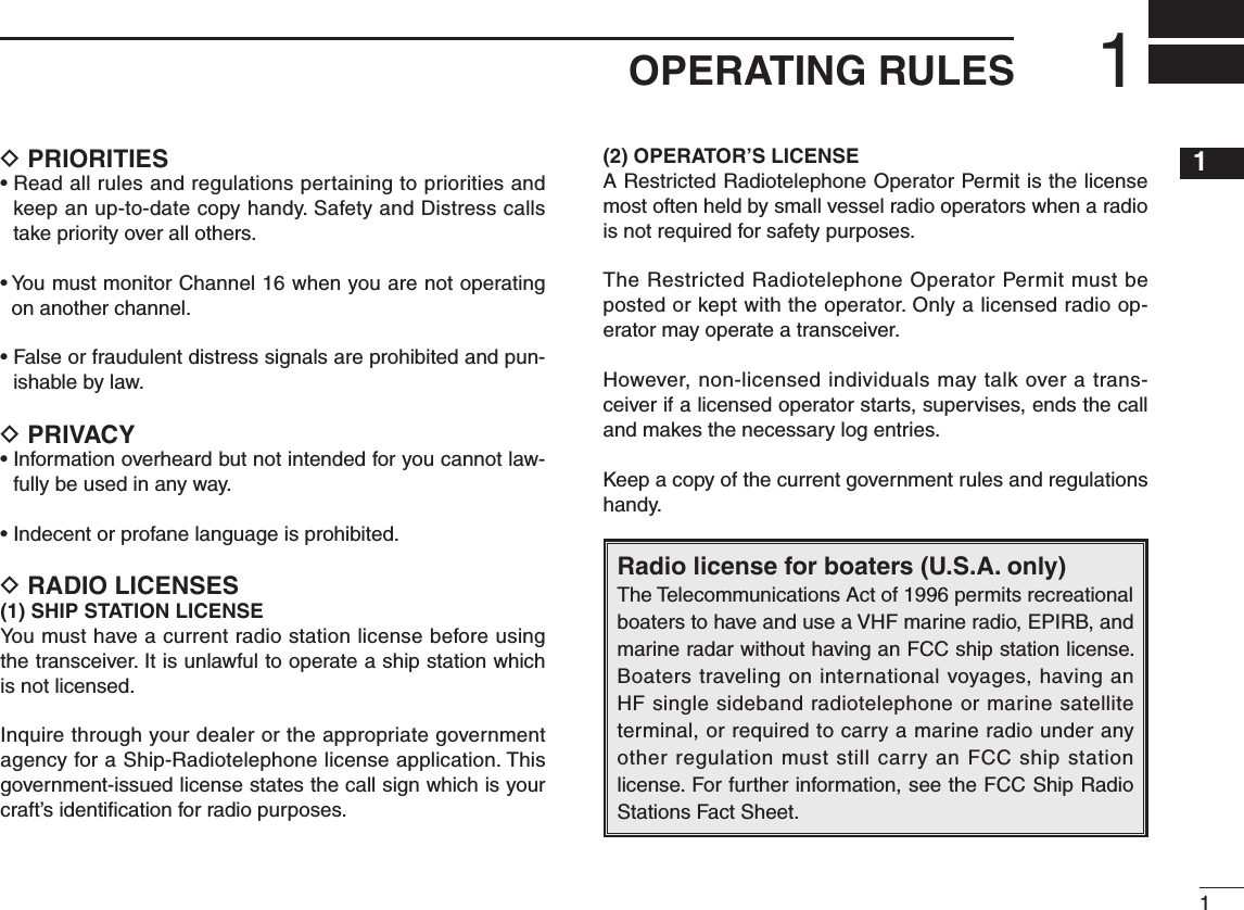
![New2001PROBLEM POSSIBLE CAUSE SOLUTION REF.No sound from speaker.•Squelchlevelistoohigh.•Volumelevelistoolow.•Speakerhasbeenexposedtowater.p. 7p. 7p. 9•Set[SQL] to the threshold point.•Set[VOL] to a suitable level.•Drainwaterfromthespeaker.The transceiver does not turn ON.•Badconnectiontothepowersupply. p. 44•Checktheconnectiontothetransceiver.Transmitting is impos-sible, or high power can not be selected.•Somechannelsareforlowpowerorre-ceive only.•Theoutputpowerissettolow.pp. 5, 6, 52p. 7•Changechannels.•Push[HI/LO] on the microphone to select high power.Scan does not start. •TAGchannelisnotprogrammed. •SetadesiredchannelsasTAGchannels. p. 11No beeps. •BeeptonesareturnedOFF. •TurnthebeeptoneONintheSetmode. p. 42Distress call cannot be transmitted.•MMSI(DSCselfID)codeisnotpro-grammed.•ProgramtheMMSI(DSCselfID)code. p. 1352New2001TROUBLESHOOTING9](https://usermanual.wiki/ICOM-orporated/305400/User-Guide-1344860-Page-58.png)