ICOM orporated 305400 VHF Marine Transceiver User Manual
ICOM Incorporated VHF Marine Transceiver
User Manual
INSTRUCTION MANUAL
New2001
iM412
VHF MARINE TRANSCEIVER

i
New2001
FOREWORD
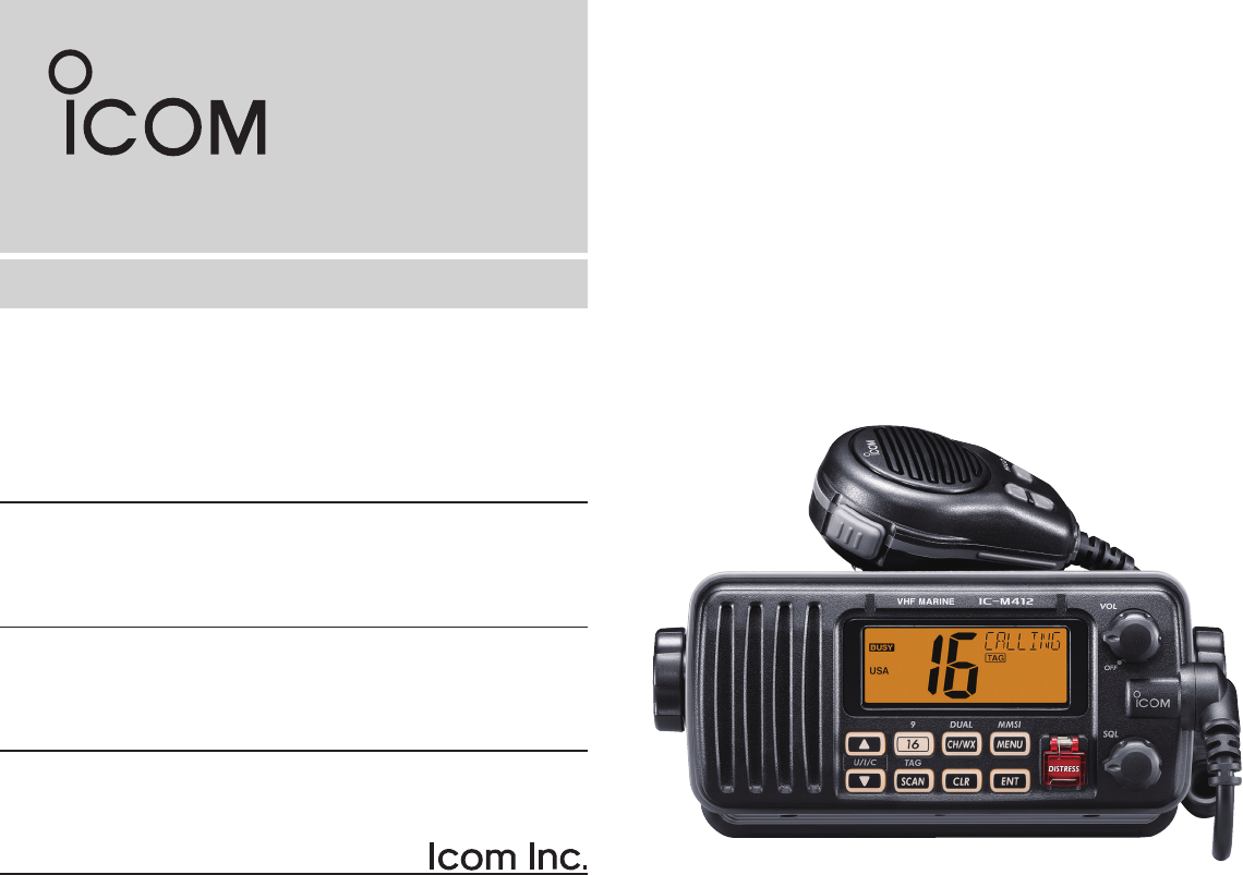
Thank you for purchasing this Icom product. The IC-M412
vhf marine transceiver is designed and built with Icom’s
state of the art technology and craftsmanship. With proper
care, this transceiver should provide you with years of trou-
ble-free operation.
We appreciate you making the IC-M412 your radio of choice,
and hope you agree with Icom’s philosophy of “technology first.”
Many hours of research and development went into the de-
sign of your IC-M412.
D FEATURES
m Advanced receiver performance
m Easy to hear speaker
m Built-in DSC meets Class D requirement
m Rugged waterproof construction
m Favorite channel function
m AquaQuake water draining function
IMPORTANT
READ ALL INSTRUCTIONS carefully and completely
before using the transceiver.
SAVE THIS INSTRUCTION MANUAL — This in-
struction manual contains important operating instructions
for the IC-M412.
EXPLICIT DEFINITIONS
WORD DEFINITION
R WARNING!
CAUTION
NOTE
Personal injury, fire hazard or electric
shock may occur.
Equipment damage may occur.
Recommended for optimum use. No risk of
personal injury, fire or electric shock.
CLEAN THE TRANSCEIVER AND MICROPHONE
THOROUGHLY WITH FRESH WATER after exposure
to water including salt water, otherwise, the keys and
switches may become inoperable due to salt crystalliza-
tion.
Icom, Icom Inc. and the Icom logo are registered trademarks of Icom Incor-
porated (Japan) in Japan, the United States, the United Kingdom, Germany,
France, Spain, Russia and/or other countries.
ii
New2001
IN CASE OF EMERGENCY
If your vessel requires assistance, contact other vessels and
the Coast Guard by sending a Distress call on Channel 16.
USING CHANNEL 16
DISTRESS CALL PROCEDURE
1. “MAYDAY MAYDAY MAYDAY.”
2. “THIS IS ...............” (name of vessel)
3. Your call sign or other indication of the vessel (AND
9-digit DSC ID if you have one).
4. “LOCATED AT ...............” (your position)
5. The nature of the distress and assistance required.
6. Any other information which might facilitate the rescue.
Or, transmit your Distress call using digital selective calling
on Channel 70.
USING DIGITAL SELECTIVE CALLING (Ch 70)
DISTRESS CALL PROCEDURE
1. While lifting up the key cover, hold down [DISTRESS]
for 5 seconds until you hear 5 short beeps change to
one long beep.
2. Wait for an acknowledgment on Channel 70 from a
coast station.
•Aftertheacknowledgementisreceived,Channel16is
automatically selected.
3. Hold down [PTT], then transmit the appropriate
information as listed above.
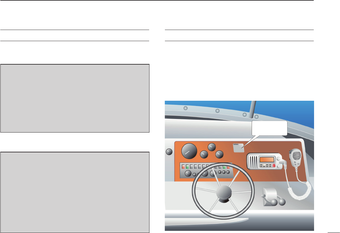
NOTE
A WARNING STICKER is supplied with the transceiver.
To comply with FCC regulations, this sticker must be affixed in
such a location as to be readily seen from the operating
controls of the radio as in the diagram below. Make sure the
chosen location is clean and dry before applying the sticker.
(p. 36)
EXAMPLE
WARNING
STICKER

iii
New2001
RADIO OPERATOR WARNING
WARNING
Icom requires the radio operator to meet the
FCC Requirements for Radio Frequency
Exposure. An omnidirectional antenna with
gain not greater than 9 dBi must be mounted a
minimum of 5 meters (measured from the
lowest point of the antenna) vertically above
the main deck and all possible personnel. This is the
minimum safe separation distance estimated to meet all RF
exposure compliance requirements. This 5 meter distance is
based on the FCC Safe Maximum Permissible Exposure
(MPE) distance of 3 meters added to the height of an adult
(2 meters) and is appropriate for all vessels.
For watercraft without suitable structures, the antenna
must be mounted so as to maintain a minimum of 1 meter
vertically between the antenna, (measured from the lowest
point of the antenna), to the heads of all persons AND all
persons must stay outside of the 3 meter MPE radius.
Do not transmit with radio and antenna when persons are
within the MPE radius of the antenna, unless such persons
(such as driver or radio operator) are shielded from antenna
field by a grounded metallic barrier. The MPE Radius is the
minimum distance from the antenna axis that person should
maintain in order to avoid RF exposure higher than the
allowable MPE level set by FCC.
FAILURE TO OBSERVE THESE LIMITS MAY ALLOW
THOSE WITHIN THE MPE RADIUS TO EXPERIENCE RF
RADIATION ABSORPTION WHICH EXCEEDS THE FCC
MAXIMUM PERMISSIBLE EXPOSURE (MPE) LIMIT.
IT IS THE RESPONSIBILITY OF THE RADIO OPERATOR
TO ENSURE THAT THE MAXIMUM PERMISSIBLE
EXPOSURE LIMITS ARE OBSERVED AT ALL TIMES
DURING RADIO TRANSMISSION. THE RADIO
OPERATOR IS TO ENSURE THAT NO BYSTANDERS
COME WITHIN THE RADIUS OF THE MAXIMUM
PERMISSIBLE EXPOSURE LIMITS.
Determining MPE Radius
THE MAXIMUM PERMISSIBLE EXPOSURE (MPE)
RADIUS HAS BEEN ESTIMATED TO BE A RADIUS OF
ABOUT 3M PER OET BULLETIN 65 OF THE FCC.
THIS ESTIMATE IS MADE ASSUMING THE MAXIMUM
POWER OF THE RADIO AND ANTENNAS WITH A
MAXIMUM GAIN OF 9dBi ARE USED FOR A SHIP
MOUNTED SYSTEM.

iv
New2001
TABLE OF CONTENTS
FOREWORD ..................................................................................... i
IMPORTANT ...................................................................................... i
EXPLICIT DEFINITIONS ................................................................... i
IN CASE OF EMERGENCY ............................................................. ii
NOTE ................................................................................................ ii
RADIO OPERATOR WARNING ...................................................... iii
TABLE OF CONTENTS ................................................................... iv
PRECAUTIONS ................................................................................ v
1 OPERATING RULES ..................................................................1
2 PANEL DESCRIPTION ........................................................... 2–4
n Front panel ...............................................................................2
n Microphone ..............................................................................3
n Function display .......................................................................4
3 BASIC OPERATION ...............................................................5–9
n Channel selection ....................................................................5
n Receiving and transmitting ......................................................7
n Call channel programming .......................................................8
n Channel comments ..................................................................8
n Microphone Lock function ........................................................9
n Display backlight ......................................................................9
n AquaQuake water draining function .........................................9
4 SCAN OPERATION ............................................................10–11
n Scan types .............................................................................10
n Setting TAG channels ............................................................11
n Starting a scan .......................................................................11
5 DUALWATCH/TRI-WATCH .......................................................12
n Description .............................................................................12
n Operation ...............................................................................12
6 DSC OPERATION ............................................................... 13–40
n MMSI code programming ......................................................13
n DSC address ID .....................................................................14
n Position and time programming .............................................17
n Position indication ..................................................................18
n Distress call ...........................................................................18
n Transmitting DSC calls ...........................................................21
n Receiving DSC calls ..............................................................34
n Received messages ..............................................................38
n Automatic acknowledgement ................................................40
n Offset time .............................................................................40
7 SET MODE ..........................................................................41–43
n Set mode programming .........................................................41
n Set mode items ......................................................................42
8 CONNECTIONS AND MAINTENANCE..............................44–47
n Connections ...........................................................................44
n Antenna .................................................................................45
n Fuse replacement ..................................................................45
n Cleaning.................................................................................45
n Supplied accessories .............................................................45
n Mounting the transceiver .......................................................46
n Optional MB-69 installation ....................................................47
9 TROUBLESHOOTING ..............................................................48
10 SPECIFICATIONS AND OPTION .......................................49–51
n Specifications.........................................................................49
n Option ....................................................................................51
11 CHANNEL LIST ..................................................................52–53
12 TEMPLATE ...............................................................................55

v
New2001
RWARNING! NEVER connect the transceiver to an
AC outlet. This may pose a fire hazard or result in an electric
shock.
CAUTION: Changes or modifications to this device, not
expressly approved by Icom Inc., could void your authority to
operate this device under FCC regulations.
RWARNING! NEVER connect the transceiver to a
power source of more than 16 V DC or use reverse polarity.
This will ruin the transceiver.
RWARNING! NEVER cut the DC power cable between
the DC plug at the back of the transceiver and fuse holder. If
an incorrect connection is made after cutting, the transceiver
may be damaged.
CAUTION: NEVER place the transceiver where normal
operation of the vessel may be hindered or where it could
cause bodily injury.
CAUTION: KEEP the transceiver at least 3.3 ft (1 m)
away from the ship’s navigation compass.
DO NOT use or place the transceiver in areas with tem-
peratures below –4°F (–20°C) or above +140°F (+60°C), or
in areas subject to direct sunlight, such as the dashboard.
DO NOT use harsh solvents such as benzine or alcohol to
clean the transceiver, as they will damage the transceiver’s
surfaces. If the transceiver becomes dusty or dirty, wipe it
clean with a soft, dry cloth.
BE CAREFUL! The transceiver rear panel will become
hot when operating continuously for long periods of time.
Place the transceiver in a secure place to avoid inadvertent
use by children
BE CAREFUL! The transceiver employs waterproof
construction, which corresponds to IPX7 of the international
standard IEC 60529 (2001). However, once the transceiver
has been dropped, waterproofing cannot be guaranteed due
to the fact that the case may be cracked, or the waterproof
seal damaged, etc.
Approved Icom optional equipment is designed for optimal
performance when used with an Icom transceiver.
Icom is not responsible for the destruction or damage to an
Icom transceiver in the event the Icom transceiver is used
with equipment that is not manufactured or approved by
Icom.
PRECAUTIONS

1
1
OPERATING RULES
D PRIORITIES
•Readallrulesandregulationspertainingtoprioritiesand
keep an up-to-date copy handy. Safety and Distress calls
take priority over all others.
•YoumustmonitorChannel16whenyouarenotoperating
on another channel.
•Falseorfraudulentdistresssignalsareprohibitedandpun-
ishable by law.
D PRIVACY
•Informationoverheardbutnotintendedforyoucannotlaw-
fully be used in any way.
•Indecentorprofanelanguageisprohibited.
D RADIO LICENSES
(1) SHIP STATION LICENSE
You must have a current radio station license before using
the transceiver. It is unlawful to operate a ship station which
is not licensed.
Inquire through your dealer or the appropriate government
agency for a Ship-Radiotelephone license application. This
government-issued license states the call sign which is your
craft’s identification for radio purposes.
(2) OPERATOR’S LICENSE
A Restricted Radiotelephone Operator Permit is the license
most often held by small vessel radio operators when a radio
is not required for safety purposes.
The Restricted Radiotelephone Operator Permit must be
posted or kept with the operator. Only a licensed radio op-
erator may operate a transceiver.
However, non-licensed individuals may talk over a trans-
ceiver if a licensed operator starts, supervises, ends the call
and makes the necessary log entries.
Keep a copy of the current government rules and regulations
handy.
1
Radio license for boaters (U.S.A. only)
The Telecommunications Act of 1996 permits recreational
boaters to have and use a VHF marine radio, EPIRB, and
marine radar without having an FCC ship station license.
Boaters traveling on international voyages, having an
HF single sideband radiotelephone or marine satellite
terminal, or required to carry a marine radio under any
other regulation must still carry an FCC ship station
license. For further information, see the FCC Ship Radio
Stations Fact Sheet.
2
New2001
PANEL DESCRIPTION
2
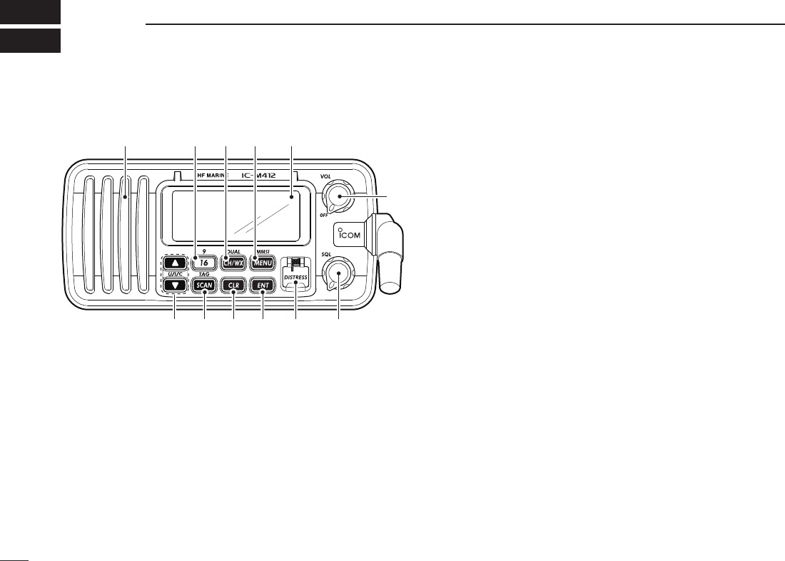
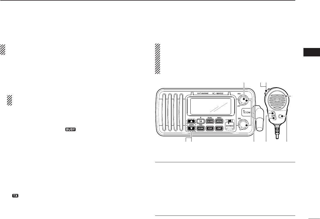
n Front panel
Function display (p. 4)Speaker i!0o
weuytr
q
qPOWER•VOLUMECONTROL[VOL]
➥ Rotate to turn the transceiver power ON or OFF.
➥ Rotate to adjust the audio level.
w SQUELCH CONTROL [SQL] (p. 7)
Rotate to set the squelch threshold level.
e DISTRESS KEY [DISTRESS] (p. 18)
Hold down for 5 seconds to transmit a Distress call.
r ENTER KEY [ENT]
Push to set the DSC menu, a channel comment, etc.
t CLEAR KEY [CLR]
Push to cancel the entered function, or exits the Set
mode.
ySCAN•TAGCHANNELKEY
[SCAN]•[TAG](SCAN) (p. 11)
➥ Push to start and stop the Normal or Priority scan.
➥ Hold down for 1 second to set or clear the displayed
channel as a tag (scanned) channel.
➥ While holding down [HI/LO] on the microphone, hold
down this key for 3 seconds to set or clear all tag chan-
nels in the selected channel group.
uCHANNELUP/DOWN•CHANNELGROUPKEYS
[s]/[t]•[U/I/C]
➥ Push to select the operating channels, Set mode set-
tings, DSC menu items, etc. (pp. 5, 6, 13, 41)
➥ Hold down [Y] to continuously move upward through
the operating channels.
➥ Hold down [Z] to continuously move downward
through the operating channels
➥ Push both keys to select one of three channel groups
in sequence. (p. 6)
•USA,InternationalandCanadianchannelsareselectable.
➥ While holding down [SCAN], push [Y] or [Z] to adjust
the brightness of the LCD and key backlight. (p. 9)
➥ While holding down both keys, turn ON the power to
activates the AquaQuake function. (p. 9)
➥ During scan operation, Checks TAG channels, changes
scanning direction or resumes the scan manually. (p. 11)

3
2
PANEL DESCRIPTION
New2001
iCHANNEL16/CALLCHANNELKEY[16]•[9](16)
➥ Push to select Channel 16. (p. 5)
➥ Hold down for 1 second to select Call channel. (p. 5)
•“CALL” appears when Call channel is selected.
➥ When the Call channel is selected, hold down for 3 sec-
onds to enter the Call channel programming mode. (p. 8)
➥ While holding down [CH/WX], push to enter the chan-
nel comment programming mode. (p. 8)
➥ While in the channel comment programming mode,
push to move the cursor backward. (p. 9)
➥
While holding down this key, turn ON the power to enter
the Set mode. (p. 41)
o CHANNEL/WEATHER CHANNEL KEY /DUALWATCH/
TRI-WATCHKEY[CH/WX]•[DUAL](CH/WX)
➥ Selects and toggles the regular channel and Weather
channel when pushed momentarily. (pp. 5, 6)
➥ Hold down for 1 second to start Dualwatch or Tri-watch.
(p. 12)
•PushtostopDualwatchorTri-watchwheneitherisactivated.
➥ While in the channel comment programming mode,
push to advance the cursor. (p. 9)
!0DSCMENUKEY[MENU]•[MMSI](MENU) (p. 13)
➥ Push to turn the DSC menu ON or OFF.
➥ Hold down for 1 second to display the MMSI code on
the channel comment indicator. (pp. 5, 6)
n Microphone
Microphone
q
e
w
q PTT SWITCH [PTT]
Hold down to transmit; release to receive. (p. 7)
w CHANNEL UP/DOWN KEYS [Y]/[Z]
➥ Push to select the operating channels, Set mode set-
tings, DSC menu items, etc. (pp. 5, 6, 13, 41)
➥ During scan operation, checks TAG channels, changes
scanning direction or manually resumes the scan.
(p. 11)
e TRANSMIT POWER KEY [HI/LO]
➥ Push to select the output power high or low. (p. 7)
•Somechannelsaresettolowpoweronly.
➥
While holding down this key, turn ON the power to tog-
gle the Microphone Lock function ON or OFF. (p. 9)
2
4
2PANEL DESCRIPTION
New2001
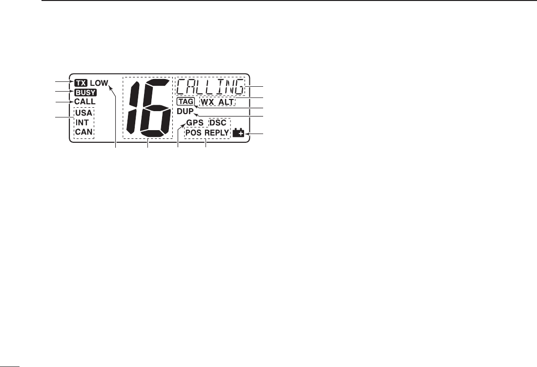
n Function display
yio u
!2
!3
!1
!0
w
e
r
t
q
q CHANNEL COMMENT INDICATOR
➥ Channel comment appears and scrolls for about 10 sec-
onds after the channel selection, if programmed. (p. 8)
➥ “ SCAN 16” appears during Priority scan; “SCAN” ap-
pears during Normal scan. (p. 11)
➥ “DW 16” appears during Dualwatch; “TW 16” appears
during Tri-watch. (p. 12)
➥ In the Set mode, displays and scrolls the selected item. (p. 41)
w WEATHER CHANNEL ICONS (pgs. 6, 33)
➥ “ WX” appears when a weather channel is selected.
➥ “ WX ALT” appears when the Weather Alert function is
in use; blinks when an alert tone is received.
e TAG CHANNEL ICON (p. 11)
Appears when a TAG channel is selected.
r DUPLEX ICON (p. 6)
Appears when a duplex channel is selected.
t LOW BATTERY ICON
Appears when the battery voltage drops to approximately
10 V DC or below.
y DSC ICONS
Indicates the DSC status.
•“DSC” appears when a DSC call is received. (pp. 23, 34)
•“POS REPLY” appears when a Position Reply call is received.
(p. 37)
u GPS INDICATOR
➥ Appears while valid position data is received.
➥ Blinks when invalid position data is received.
➥ Disappears when no GPS receiver is connected.
i CHANNEL NUMBER READOUT
➥ Indicates the selected operating channel number.
•“A” appears when a simplex channel is selected.
➥ In the Set mode, displays the selected option. (p. 41)
o LOW POWER ICON (p. 7)
Appears when low power is selected.
!0 CHANNEL GROUP ICON (p. 6)
Displays whether a U.S.A. “USA,” International “INT” or
Canadian “CAN” channel group is selected.
!1 CALL CHANNEL ICON (p. 5)
Appears when the Call channel is selected.
!2 BUSY ICON (p. 7)
Appears when receiving a signal or when the squelch
opens.
!3 TRANSMIT ICON (p. 7)
Appears while transmitting.
5
3
BASIC OPERATION
2
3
n Channel selection
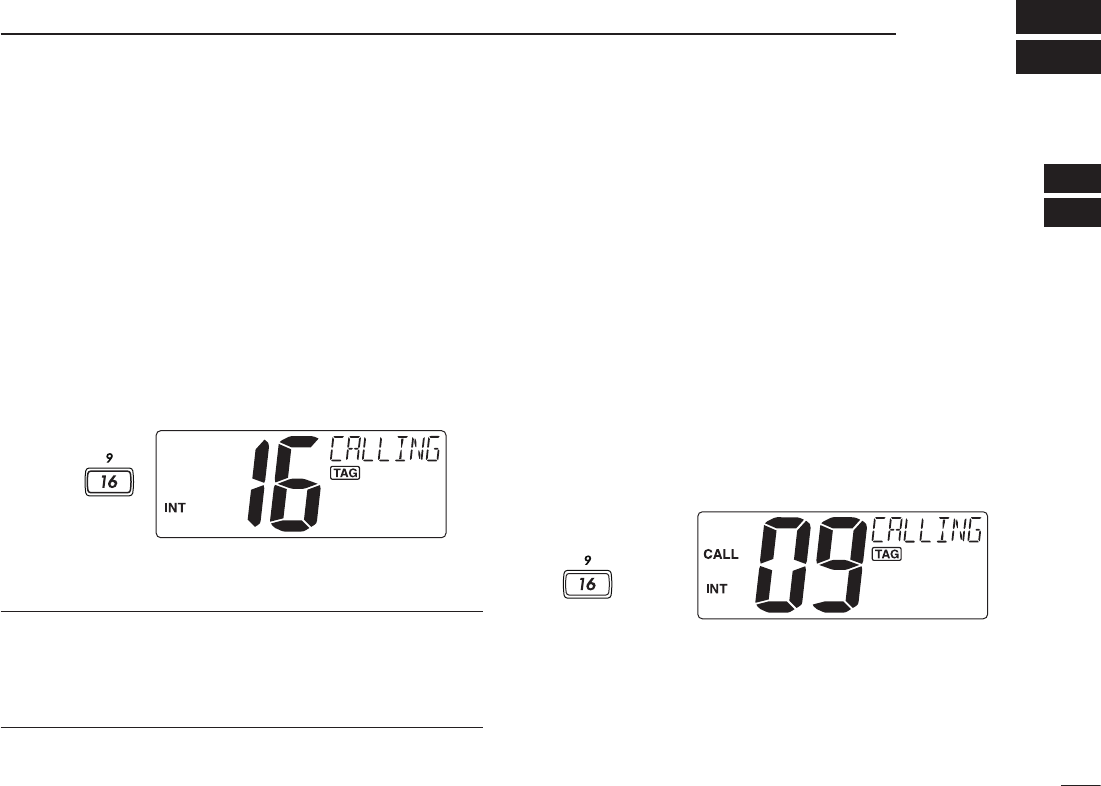
ï Channel 16
Channel 16 is the distress and safety channel. It is used for
establishing initial contact with a station and for emergency
communications. Channel 16 is monitored during both Du-
alwatch and Tri-watch. While standing by, you must monitor
Channel 16.
➥ Push [16] momentarily to select Channel 16.
➥ Push [CH/WX] to return to the display before selecting
Channel 16, or push [Y] or [Z] to select an operating
channel.
Push
Convenient!
When the Favorite channel function is turned ON (p. 43),
[Y]/[Z] keys on the microphone select the favorite channels
in the selected channel group in sequence when pushed.
•ThefavoritechannelsaresetbytheTAGchannelsetting.(p.11)
ï Channel 9 (Call channel)
Each regular channel group has a separate leisure-use Call
channel. The Call channel is monitored during Tri-watch. The
Call channels can be programmed (p. 8) and are used to
store your most often used channel in each channel group
for quick recall.
➥ Hold down [9](16) for 1 second to select the Call channel
of the selected channel group.
•“CALL” and Call channel number appear.
•EachchannelgroupmayhaveanindependentCallchannel
after programming a Call channel. (p. 8)
➥ Push [CH/WX] to return to the display before selecting
Call channel, or push [Y] or [Z] to select an operating
channel.
Hold down
for 1 sec.
6
3BASIC OPERATION
New2001
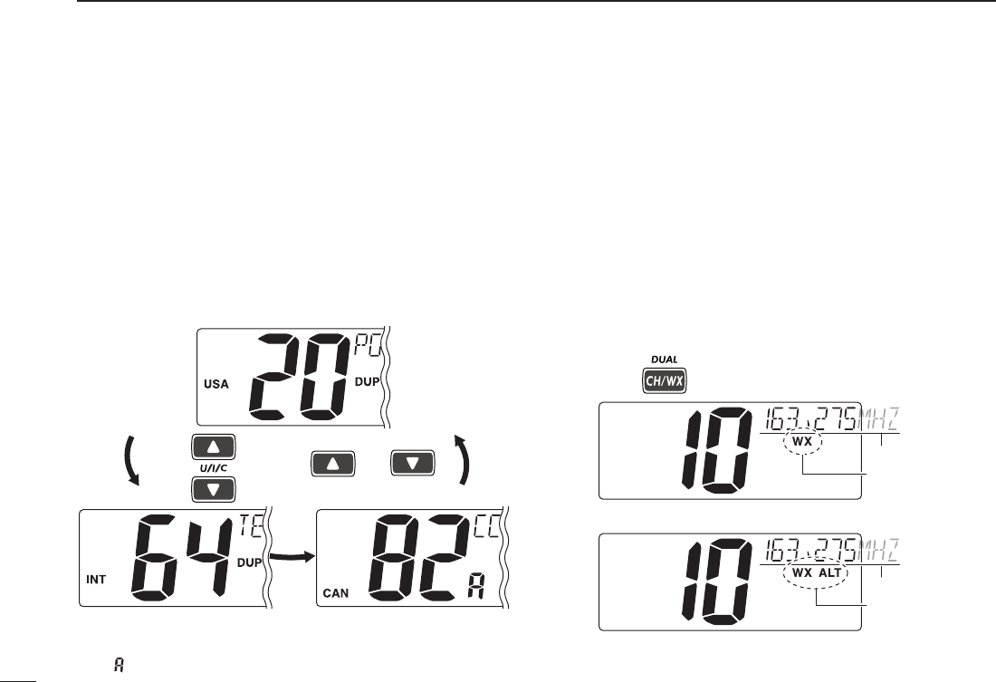
ï U.S.A., international and Canadian
channels
The IC-M412 is pre-programmed with 57 USA, 57 interna-
tional and 61 Canadian channels. These channel groups
may be specified for the operating area.
q Push [CH/WX] to select a regular channel.
•Ifaweatherchannelappears,push[CH/WX] again.
e Push [U/I/C] (both [Y] and [Z]) to change the channel
group. (p. 6)
•USA,InternationalandCanadianchannelgroupscanbese-
lected in sequence.
both ()and
Push
e Push [Y] or [Z] to select a channel.
•“DUP” appears for duplex channels.
•“ ” appears when a simplex channel is selected.
ï Weather channels
The IC-M422 has 10 weather channels. These are used for
monitoring broadcasts from NOAA (National Oceanic and
Atmospheric Administration.)
The transceiver can detect a weather alert tone on the se-
lected weather channel while receiving the channel, during
standby on a regular channel or while scanning. (p. 33)
q Push [CH/WX] once or twice to select a weather chan-
nel.
•“WX” appears when a weather channel is selected.
•“WX ALT” appears when the Weather Alert function is in use.
(p. 33)
Scrolls
Appears
Scrolls
Appears
When Weather alert is OFF.
When Weather alert is ON.
Push once or twice
w Push [Y] or [Z] to select a channel.
7
3
BASIC OPERATION
New2001
3
n Receiving and transmitting
CAUTION: Transmitting without an antenna may dam-
age the transceiver.
q Rotate [VOL] to turn ON the power.
w Set the audio and squelch levels.
➥Rotate [SQL] fully counterclockwise.
➥Rotate [VOL] to adjust the audio output level.
➥Rotate [SQL] clockwise until the noise disappears.
While in the DSC operation, please make sure you set
the squelch correctly.
e Push [U/I/C] (both [Y] and [Z]) to change the channel
group. (p. 6)
r Push [Y] or [Z] to select a desired channel. (pp. 5, 6, 52)
•Whenreceivingasignal,“ ” appears and audio is emitted
from the speaker.
•Furtheradjustmentof[VOL] may be necessary.
t Push [HI/LO] on the microphone to select the output
power if necessary.
•“LOW” appears when low power is selected.
•Chooselowpowerforshortrangecommunications,choose
high power for longer distance communications.
•Somechannelsareforlowpoweronly.
y Hold down [PTT] to transmit, then speak into the micro-
phone (*).
•“ ” appears.
•Channel70cannotbeusedfortransmissionotherthanDSC.
u Release [PTT] to receive.
IMPORTANT: To maximize the readability of your trans-
mitted signal, pause a few seconds after holding down
[PTT], hold the microphone 5 to 10 cm from your mouth
and speak into the microphone (*) at a normal voice
level.
u
w
re
M
qy
rt
M: Microphone
4 NOTE for TOT (Time-out Timer) function
The TOT function inhibits continuous transmission over a
preset time period after the transmission starts.
A beep sounds 10 seconds before the TOT function acti-
vates, to indicate the transmission will be shut down and
“TOT” appears on the channel comment indicator. Transmis-
sion is not possible for 10 seconds after this transmission
shut down.
8
3BASIC OPERATION
New2001
n Call channel programming
Call channel is used to select Channel 9 (default), however,
you can program the Call channel with your most often-used
channels in each channel group for quick recall.
q Push both [Y] and [Z] on the transceiver one or more
times to select a desired channel group (U.S.A., Interna-
tional or Canada) to be programmed.
w Hold down [9](16) for 1 second to select the Call channel
of the selected channel group.
•“CALL” and Call channel num-
ber appear.
e Hold down [9](16) again for
3 seconds (until a long beep
changes to two short beeps)
to enter the Call channel
programming mode.
•Channelnumberstartsblink-
ing.
r Push [Y] or [Z] to select a
desired channel.
t Push [9](16) to program the
displayed channel as the
Call channel.
•Push[CLR] to cancel.
•Thechannelnumberstops
blinking.
n Channel comments
The channels can be labeled with a unique alphanumeric ID
of up to 10 characters.
Comment is indicated at the channel comment indicator for
about 10 seconds after the channel selection, and the com-
ment, more than 7 characters long, automatically scrolls.
Capital letters, small letters (except f, j, k, p, s, v, x, z), 0 to 9,
some symbols (= M + – . /) and space can be used.
q Select a desired channel.
•CancelDualwatch,Tri-watchorScaninadvance.
w While holding down [CH/
WX], push [16] to edit the
channel comment program-
ming mode.
•Acursorandthefirstcharac-
ter start blinking alternately.
e Push [Y] or [Z] to select a desired character.
•Push[CH/WX] or [16] to move the cursor forward or backward.
r Repeat step e to input all characters.
t Push [ENT] to input and set the comment.
•Push[CLR] to cancel and exit the programming mode.
•Thecursorandthecharacterstopblinking.
y If desired, repeat steps q to t to program other channel
comments.

9
3
BASIC OPERATION
New2001
3
n Microphone Lock function
The Microphone Lock function electrically locks the [Y] and
[Z] keys on the supplied microphone. This prevents acci-
dental channel changes and function access.
➥ While holding down [HI/LO] on the microphone, turn ON
the power to toggle the Microphone Lock function ON or
OFF.
[HI/LO]
[Y]/[Z]
n Display backlight
The function display and keys can be backlit for better visibil-
ity under low light conditions.
Display backlight is also adjustable via the Set mode. (p. 43)
➥ While holding down [SCAN], push [Y] or [Z] to adjust
the brightness of the LCD and key backlight.
•Thebacklightisadjustablein4levelsandOFF.
n AquaQuake water draining
function
The IC-M412 uses a technology to clear water away from
the speaker grill: AquaQuake. AquaQuake helps drain water
away from the speaker housing (water that might otherwise
muffle the sound coming from the speaker). The IC-M412
emits a vibrating noise when this function is being used.
➥ While holding down both [Y] and [Z] on the transceiver,
turn ON the power to activate the AquaQuake function.
•Whilecontinuingtopush[Y] and [Z], a low beep tone sounds
to drain water, regardless of the [VOL] control setting.
•WhiletheAquaQuakefunctionisactivated,thetransceiver
never accepts any key operations.
•Release[Y] and [Z] to cancel the AquaQuake function.
10
New2001
SCAN OPERATION
4
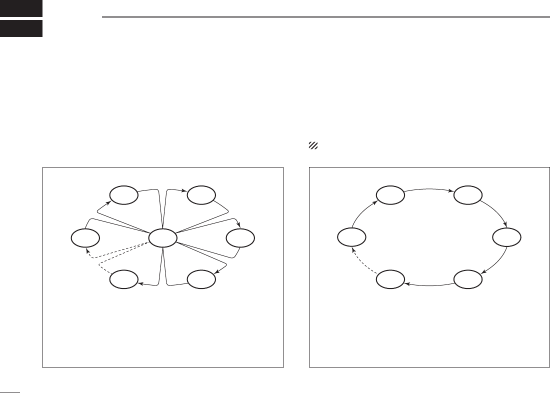
n Scan types
Scanning is an efficient way to locate signals quickly over a
wide frequency range. The transceiver has Priority scan and
Normal scan.
When the Weather Alert function is turned ON, the previ-
ously selected (last used) weather channel is also checked
while scanning. (p. 33)
Set the TAG channels (scanned channel) before scanning.
Clear the TAG channels which inconveniently stop scanning,
such as those for digital communication use. (Refer to right
page for details.)
Choose Priority or Normal scan in the Set mode. (p. 42)
PRIORITY SCAN
CH 06
CH 01
CH 16
CH 02
CH 05 CH 04
CH 03
Priority scan searches through all TAG channels in se-
quence while monitoring Channel 16. When a signal is
detected on Channel 16, scan pauses until the signal
disappears; when a signal is detected on a channel other
than Channel 16, scan becomes Dualwatch until the sig-
nal disappears.
NORMAL SCAN
CH 01 CH 02
CH 06
CH 05 CH 04
CH 03
Normal scan, like Priority scan, searches through all TAG
channels in sequence. However, unlike Priority scan,
Channel 16 is not checked unless Channel 16 is set as a
TAG channel.
11
4
SCAN OPERATION
New2001
4
n Setting TAG channels
For more efficient scanning, add a desired channels as TAG
channels or clear the TAG for unwanted channels.
Channels that are not tagged will be skipped during scan-
ning. TAG channels can be independently assigned to each
channel group (USA, INT, CAN).
q Push [U/I/C] (both [Y] and [Z]) to select a desired chan-
nel group.
w Select a desired channel to be set as a TAG channel.
e Hold down [TAG](SCAN) for 1 second to set the dis-
played channel as a TAG channel.
•“ ” appears in the display.
r To cancel the TAG channel setting, repeat step e.
•“ ” disappears.
✓ Clearing (or setting) all tagged channels
While holding down [HI/LO] on the microphone, hold down
[TAG](SCAN) for 3 seconds (until a long beep changes to two
short beeps) to clear all TAG channels in the channel group.
•RepeataboveproceduretosetallTAGchannels.
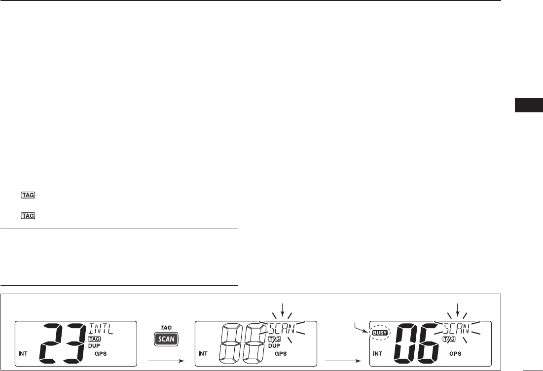
n Starting a scan
Set scan type (Priority or Normal scan) and scan resume
timer in advance, using the Set mode. (p. 42)
q Push [U/I/C] (both [Y] and [Z]) to select a desired chan-
nel group.
w Set TAG channels as described at left.
e Make sure the squelch is closed to start a scan.
r Push [SCAN] to start Priority or Normal scan.
•“SCAN”blinksatthechannelcommentindicatorduringscan-
ning. (During Priority scan, “16” appears beside the blinking
“SCAN” indication.)
•Abeeptonesoundsand“16”blinksatthechannelcommentin-
dicator when a signal is received on Channel 16 during Priority
scan.
•Whenasignalisdetected,scanpausesuntilthesignaldisap-
pears or resumes after pausing 5 seconds, depending on the
Set mode setting. (Channel 16 is still monitored during Priority
scan.)
•Push[Y] or [Z] to check the scanning TAG channels, to
change the scanning direction or resume the scan manually.
t To stop the scan, push [SCAN] again.
[Example]: Starting a Normal scan.
Push Scan starts.
When a signal is
received.
BlinksBlinks
Appears
12
New2001
DUALWATCH/TRI-WATCH
5
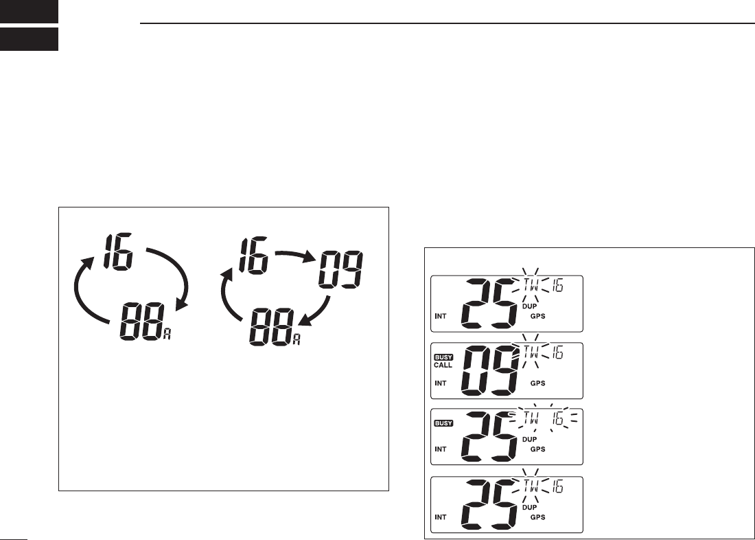
n Description
Dualwatch monitors Channel 16 while you are receiving on
another channel; Tri-watch monitors Channel 16 and the
Call channel while receiving another channel. Dualwatch/Tri-
watch is convenient for monitoring Channel 16 when you are
operating on another channel.
n Operation
q Select Dualwatch or Tri-watch in the Set mode. (p. 42)
w Push [Y] or [Z] to select a desired channel.
e Hold down [DUAL](CH/WX) for 1 second to start Dual-
watch or Tri-watch.
•“DW”blinksduringDualwatch;“TW”blinksduringTri-watch.
•Abeeptonesoundsand“16”blinkswhenasignalisreceived
on Channel 16.
r To cancel Dualwatch/Tri-watch, push [DUAL](CH/WX) again.
DUALWATCH/TRI-WATCH SIMULATION
DualwatchTri-watch
Call channel
•IfasignalisreceivedonChannel16,Dualwatch/Tri-
watch pauses on Channel 16 until the signal disappears.
•IfasignalisreceivedontheCallchannelduringTri-
watch, Tri-watch becomes Dualwatch until the signal dis-
appears.
•TotransmitontheselectedchannelduringDualwatch/
Tri-watch, hold down [PTT].
[Example]: Operating Tri-watch on INT Channel 25
Tri-watch starts.
Signal is received on Call
channel.
Signal is received on
Channel 16 takes priority.
Tri-watch resumes after
the signal disappears.
13
6
DSC OPERATION
5
6
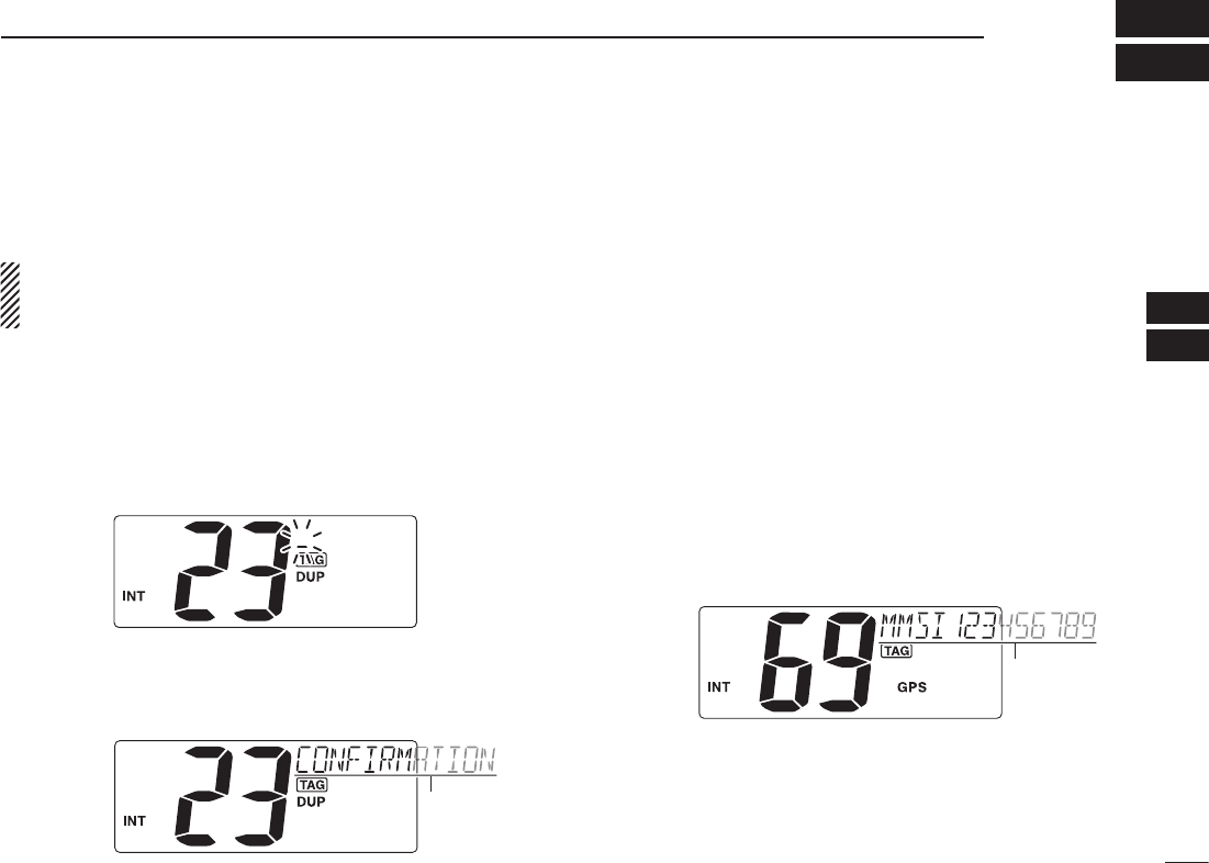
n MMSI code programming
The 9-digit MMSI (Maritime Mobile Service Identity: DSC
self ID) code can be programmed at power ON.
This function is not available when the MMSI code has
been programmed by the dealer. This code programming
can be performed only twice.
q Turn OFF the power.
w While holding down [MMSI](MENU), turn ON the power
to enter MMSI code programming mode.
e After the display appears, release [MMSI](MENU).
r Push [MENU] to enter the DSC menu.
t Push [Y] or [Z] to select “MMSI” and push [ENT].
•Acursorstartsblinking.
y Push [Y] or [Z] to select the specified MMSI code.
•Push[CH/WX] or [16] to move the cursor forward or backward.
u After programming the 9-digit MMSI code, push [ENT].
•“CONFIRMATION”scrollsatthechannelcommentindicator.
Scrolls
i Push [ENT], then input the same MMSI code as step y
for the confirmation.
o Push [ENT] to set the code.
•Returnstothenormaloperation.
•Push[CLR] to cancel and exit the programming mode.
•Ifthedifferentcodeisinput,“INCORRECT” appears. Push
[ENT] and try steps y to i again.
D MMSI code check
The 9-digit MMSI (DSC self ID) code can be checked.
➥Hold down [MMSI](MENU) for 1 second to display the
9-digit MMSI (DSC self ID) code.
•TheMMSIcodeisdisplayedandscrollsatthechannelcom-
ment indicator.
•WhennoMMSIcodeisprogrammed,“NOMMSI”appearsand
warning alarm sounds.
Scrolls
14
6DSC OPERATION
New2001
n DSC address ID
A total of 100 DSC address IDs (9-digit) can be programmed
and named with up to 10 characters.
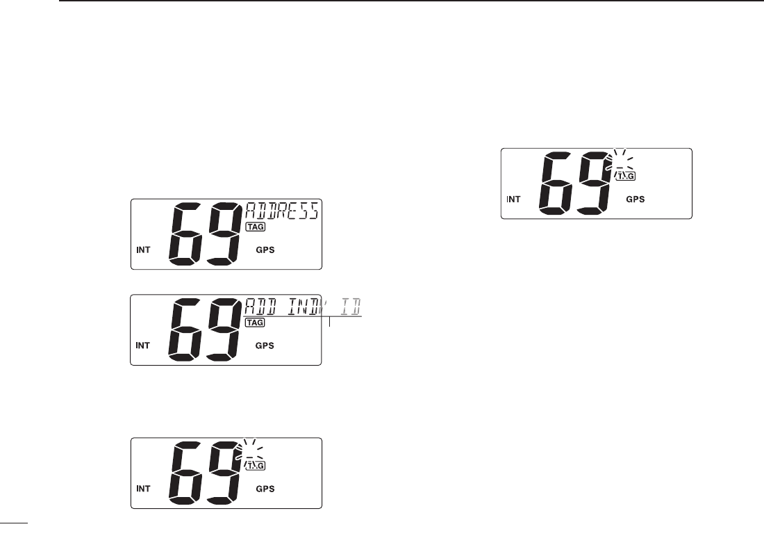
D Programming Address ID
q Push [MENU] to enter the DSC menu.
w Push [Y] or [Z] to select “ADDRESS,” push [ENT].
e Push [Y] or [Z] to select “ADD INDV ID,” push [ENT].
Scrolls
r Push [Y] or [Z] to set the 9-digit Individual ID, push
[ENT].
•Push[CH/WX] or [16] to move the cursor forward or backward.
•Push[CLR] to cancel and exit the programming mode.
t Push [Y] or [Z] to set up to a 10-character ID name.
•Push[CH/WX] or [16] to move the cursor forward or backward.
•Push[CLR] to cancel and exit the programming mode.
y Push [ENT] to program and returns to the normal opera-
tion.
15
6
DSC OPERATION
New2001
6
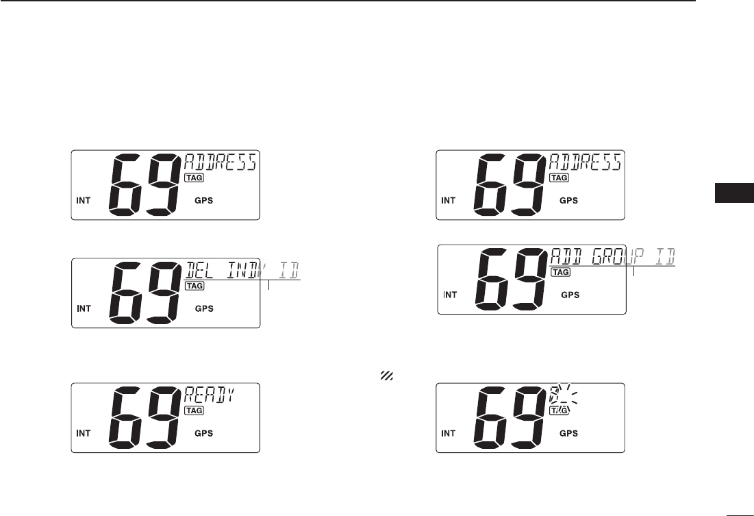
D Deleting Address ID
q Push [MENU] to enter the DSC menu.
w Push [Y] or [Z] to select “ADDRESS,” and push [ENT].
e Push [Y] or [Z] to select “DEL INDV ID,” push [ENT].
•WhennoaddressIDisprogrammed,“NOID”isdisplayed.
Scrolls
r Push [Y] or [Z] to select a desired ID name for deleting
and push [ENT].
•“READY”appears.
t Push [ENT] to delete the selected address ID and returns
to the normal operation.
D Programming Group ID
q Push [MENU] to enter the DSC menu.
w Push [Y] or [Z] to select “ADDRESS,” push [ENT].
e Push [Y] or [Z] to select “ADD GROUP ID,” push [ENT].
Scrolls
r Push [Y] or [Z] to set the 9-digit Group ID, push [ENT].
•Push[CH/WX] or [16] to move the cursor forward or backward.
•Push[CLR] to cancel and exit the condition.
1st digit ‘0’ is fixed for a Group ID.
☞ Continue to the next page
16
6DSC OPERATION
New2001
n DSC address ID
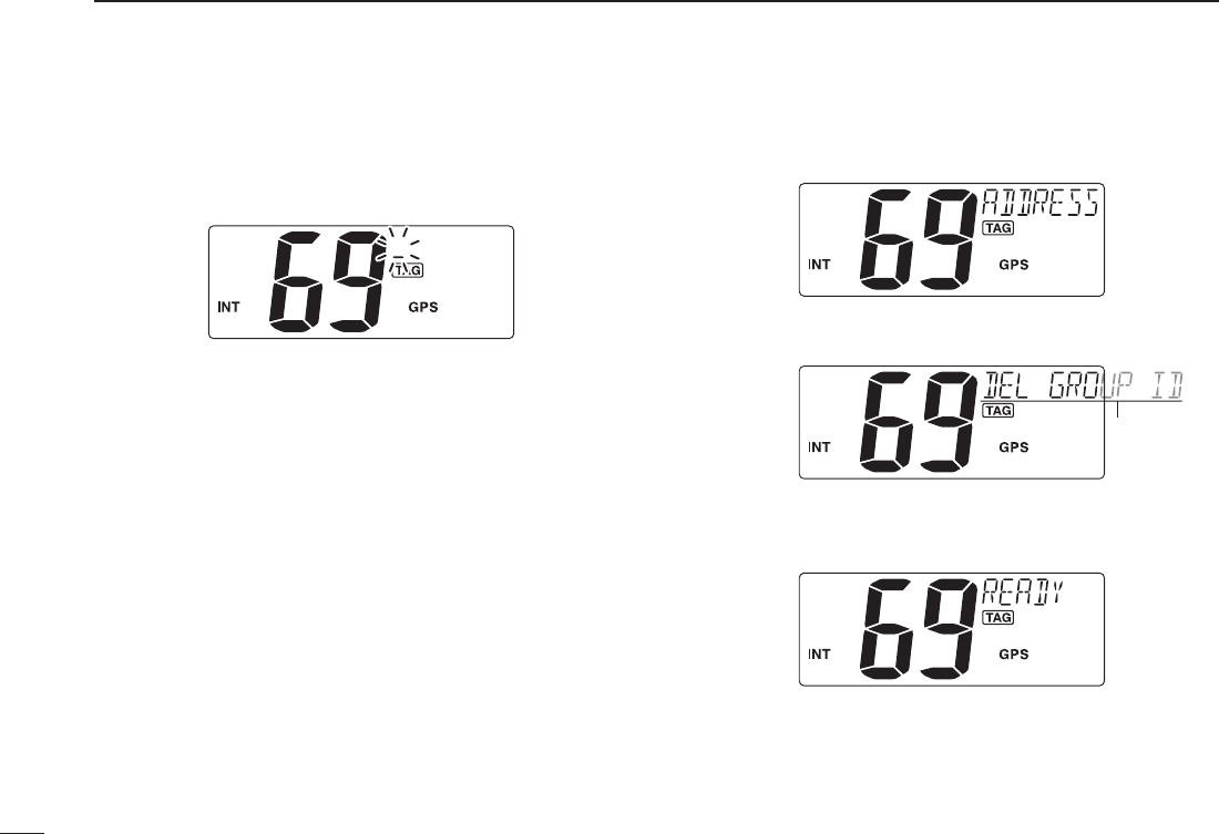
D Programming Group ID (Continued)
t Push [Y] or [Z] to set up to a 10-character ID name.
•Push[CH/WX] or [16] to move the cursor forward or backward.
•Push[CLR] to cancel and exit the programming mode.
y Push [ENT] to program and returns to the normal opera-
tion.
D Deleting Group ID
q Push [MENU] to enter the DSC menu.
w Push [Y] or [Z] to select “ADDRESS,” and push [ENT].
e Push [Y] or [Z] to select “DEL GROUP ID,” push [ENT].
•WhennogroupIDisprogrammed,“NOID”isdisplayed.
Scrolls
r Push [Y] or [Z] to select a desired ID name for deleting
and push [ENT].
•“READY”appears.
t Push [ENT] to delete the selected group ID and returns
to the normal operation.

17
6
DSC OPERATION
New2001
6
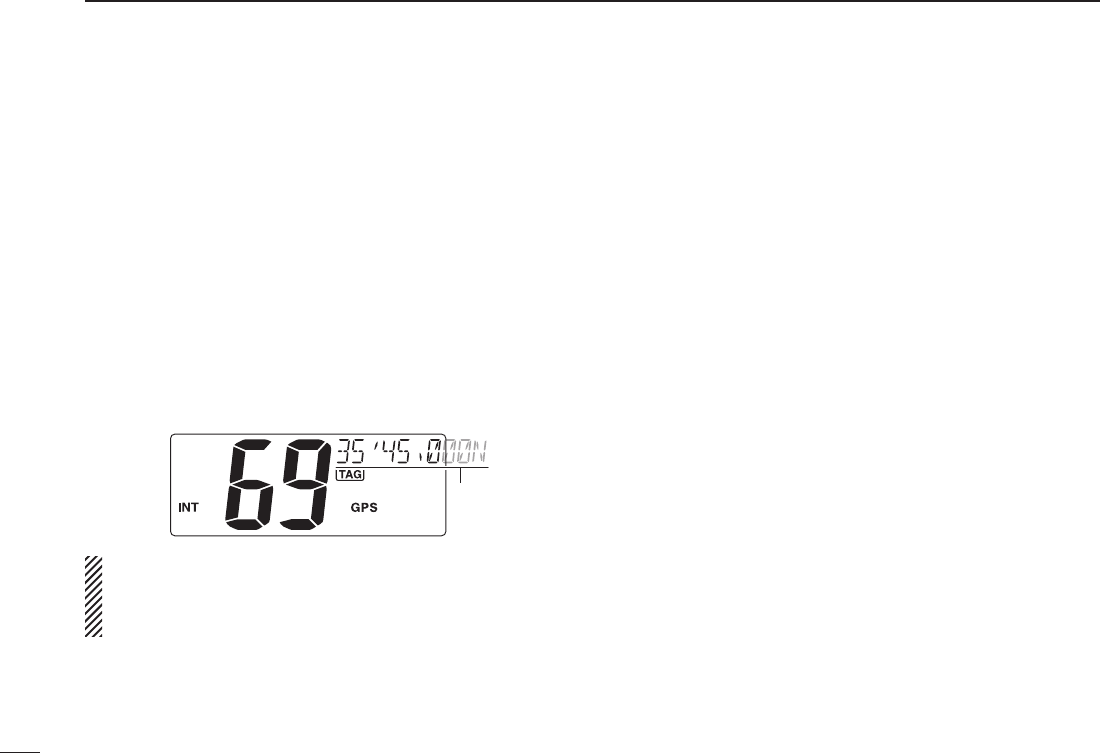
A Distress call should include the ship’s position and time
data. If no GPS is connected, your position and UTC (Uni-
versal Time Coordinated) time should be input manually.
They are included automatically when a GPS receiver
(NMEA0183 ver. 2.0 or 3.01) is connected.
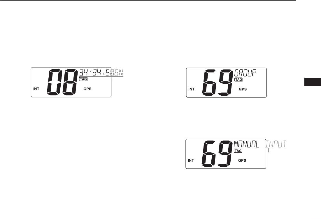
q Push [MENU] to enter the DSC menu.
w Push [s] or [t] to select “POSITION INPUT,” and push
[ENT].
Scrolls
e Push [s] or [t] to set your latitude data. After setting the
latitude data, push [ENT] to set your
longitude data
.
•Push[CH/WX] or [16] to move the cursor forward or backward.
•Push[s] or [t] to edit N; North latitude or S; South latitude
when the cursor is on the ‘N’ or ‘S’ position, and W; West lon-
gitude or E; East longitude when the cursor is on the ‘W’ or ‘E’
position.
•Push[CLR] to cancel and exit the programming mode.
r After setting the longitude data, push [ENT] to set the
current UTC time using [s] or [t].
•Push[CH/WX] or [16] to move the cursor forward or backward.
•Push[CLR] to cancel and exit the condition.
t Push [ENT] to program and returns to the normal opera-
tion.
Manually programmed position data will be held only for
23.5 hours.
“??” may blink instead of position and time indications
when the GPS data is invalid, or has not been manually
updated after 4 hours.
n Position and time programming
18
6DSC OPERATION
New2001
n Position indication
When a GPS receiver (NMEA0183 ver. 2.0 or 3.01) is con-
nected, the transceiver displays the current position data in
seconds of accuracy.
A NMEA0183 ver. 2.0 or 3.01 (sentence formatters RMC,
GGA, GNS, GLL) compatible GPS receiver is required. Ask
your dealer about suitable GPS receivers.
➥ ‘Latitude,’ ‘Longitude’ and UTC time data scroll in se-
quence at the channel comment indicator.
•Channelcommentisdisplayedforabout10secondsafterthe
channel selection.
➥ “NO POSITION” scrolls when no GPS is connected.
Scrolls
•WhentheconnectedGPSreceiveriscompatiblewith
several sentence formatters, the order of input prece-
dence is ‘RMC,’ ‘GGA,’ ‘GNS’ and ‘GLL.’
•“GPS”blinkswhentheGPSdataisinvalid.
19
6
DSC OPERATION
New2001
6
n Distress call
A Distress call should be transmitted, if in the opinion of the
Master, the ship or a person is in distress and requires im-
mediate assistance.
NEVER USE THE DISTRESS CALL WHEN YOUR
SHIP OR A PERSON IS NOT IN AN EMERGENCY.
A DISTRESS CALL CAN BE USED ONLY WHEN
IMMEDIATE HELP IS NEEDED.
D Simple call
q Confirm no Distress call is being received.
w While lifting up the key cover, hold down [DISTRESS] for
5 seconds to transmit the Distress call.
•Emergencychannel(Ch70)isautomaticallyselectedandthe
Distress call is transmitted.
•Whileholddown[DISTRESS], the key backlighting is blinking.
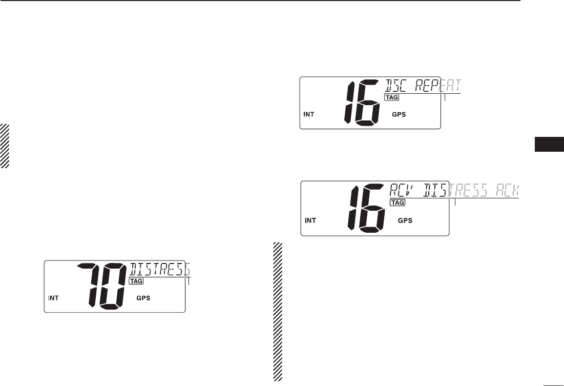
Scrolls
e After transmitting the Distress call, the transceiver waits
for an acknowledgment call on Ch16.
•TheDistresscallisautomaticallytransmittedevery3.5to4.5
minutes.
•“DSCREPEAT”scrollsatthechannelcommentindicator.
Scrolls
r After receiving the acknowledgment, reply using the mi-
crophone.
•“RCVDISTRESSACK”scrollsatthechannelcommentindica-
tor.
Scrolls
➥A distress alert contains;
•Kindsofdistress:Undesignateddistress
•Positiondata :LatestGPSormanualinputpositiondata
held for 23.5 hrs. or until the power is
turned OFF.
➥ The Distress call is repeated every 3.5–4.5 min., until
receiving an ‘acknowledgement.’ (‘Call repeat’ mode)
•“RE-TRANSMISSION”isdisplayedwhiletransmission.
➥ Push [DISTRESS] to transmit a renewed Distress call,
if desired.
➥Push [CLR] to transmit a the ‘Cancel ACK’ call to can-
cel the ‘Call repeat’ mode.
•“CANCELED”isdisplayed.
n Distress call (Continued)
D Regular call
The nature of the Distress call should be included in the Dis-
tress call.
q Push [MENU] to enter the DSC menu.
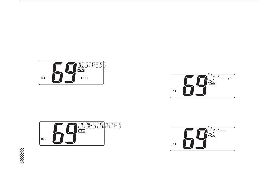
w Push [s] or [t] to select “DISTRESS,” and push [ENT].
Scrolls
e Push [s] or [t] to select the nature of the distress, and
push [ENT].
•‘UNDESIGNATED,’‘EXPLOSION,’‘FLOODING,’‘COLLISION,’
‘GROUNDING,’ ‘CAPSIZING,’ ‘SINKING,’ ‘ADRIFT (Disable
adrift),’ ‘ABANDONING (Abandoning ship),’ ‘PIRACY (Piracy at-
tack),’ and ‘MOB (Man overboard)’ are available.
•Theselectednatureofthedistressisstoredfor10minutes.
Scrolls
When a GPS receiver (NMEA0183 ver. 2.0 or 3.01) is
connected, next steps r, t (Current position/time pro-
gramming) do not appear. Go to step y.
r Push [s] or [t] to set your latitude data. After setting the
latitude data, push [ENT] to set your
longitude data
.
•Push[CH/WX] or [16] to move the cursor forward or backward,
respectively.
•
Push [s] or [t] to edit N; North latitude or S; South latitude when
the cursor is on the ‘N’ or ‘S’ position, and W; West longitude or E;
East longitude when the cursor is on the ‘W’ or ‘E’ position.
•Push[CLR] to cancel and exit the condition.
t After setting the
longitude
data, push [ENT] to set the cur-
rent UTC time using [s] or [t], then push [ENT].
•Push[CH/WX] or [16] to move the cursor forward or backward,
respectively.
•Push[CLR] to cancel and exit the condition.
20
6DSC OPERATION
New2001

21
6
DSC OPERATION
New2001
6
y Push [DISTRESS] for 3 seconds to transmit the Distress
call.
•Whilepushing[DISTRESS], the key backlighting is blinking.
•Thedistressinformationisstoredfor10minutes.
•Emergencychannel(Ch70)isautomaticallyselectedandthe
Distress call is transmitted.
•Push[CLR] to exit the condition.
Scrolls
u After transmitting the Distress call, the transceiver waits
for an acknowledgment call on Ch 16.
•TheDistresscallisautomaticallytransmittedevery3.5to4.5
min.
Scrolls
i After receiving the acknowledgment, reply using the mi-
crophone.
Scrolls
➥A distress alert contains (default);
•Natureofdistress:Selectednatureofthedistress
•Positiondata :
GPS or manual input position data is held
for 23.5 hrs or until the power is turned OFF.
➥ The Distress call is repeated every 3.5–4.5 min., until re-
ceiving an ‘acknowledgement.’ (‘Call repeat’ mode)
•“RE-TRANSMISSION”isdisplayed.
➥ Push [DISTRESS] to transmit a renewed Distress call,
if desired.
➥Push [CLR] to transmit a the ‘Cancel ACK’ call to can-
cel the ‘Call repeat’ mode.
•“CANCELED”isdisplayed.
➥ “??” may blink instead of position and time indications
when the GPS data is invalid, or has not been manu-
ally updated after 4 hours.
22
6DSC OPERATION
New2001
n Transmitting DSC calls
To ensure correct operation of the DSC function, please
make sure you set the squelch correctly. (p. 7)
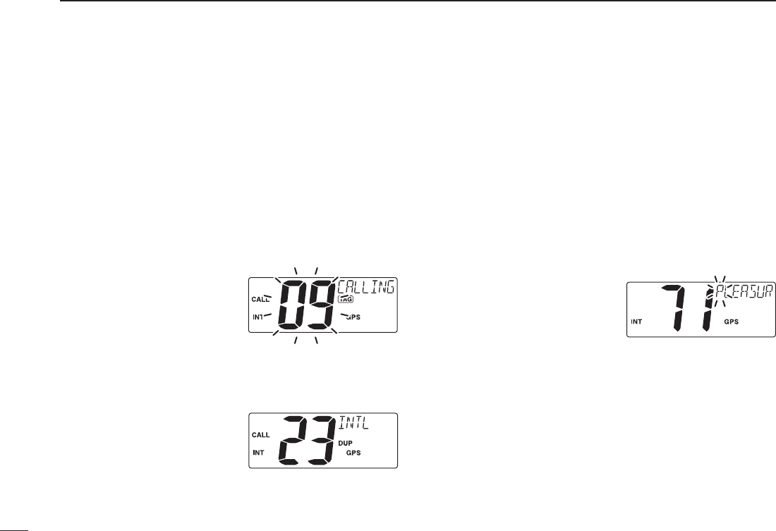
D Transmitting an Individual call
The Individual call function allows you to transmit a DSC sig-
nal to a specific ship only.
q Push [MENU] to enter the DSC menu.
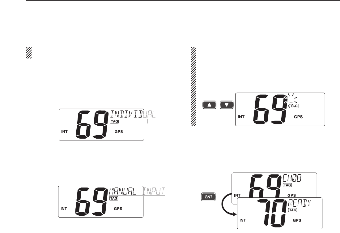
w Push [Y] or [Z] to select “INDIVIDUAL,” then push [ENT].
Scrolls
e Push [Y] or [Z] to select a desired pre-programmed Indi-
vidual address or “MANUAL INPUT,” then push [ENT].
•TheIDcodefortheindividualcanbesetinadvance.(p.14)
•When“MANUALINPUT”isselected,setthe9-digitMMSIID
code for the individual you wish to call with [Y] or [Z]. (See
About Manual Inputting; p. 22.)
Scrolls
About Manual Inputting:
Push [Y] or [Z] to input the 9-digit Individual ID, then
push [ENT].
•Push[CH/WX] or [16] to move the cursor forward or backward,
respectively.
•Push[CLR] to cancel and exit the condition.
•Gotothenextstepafterpushing[ENT].
Push
/
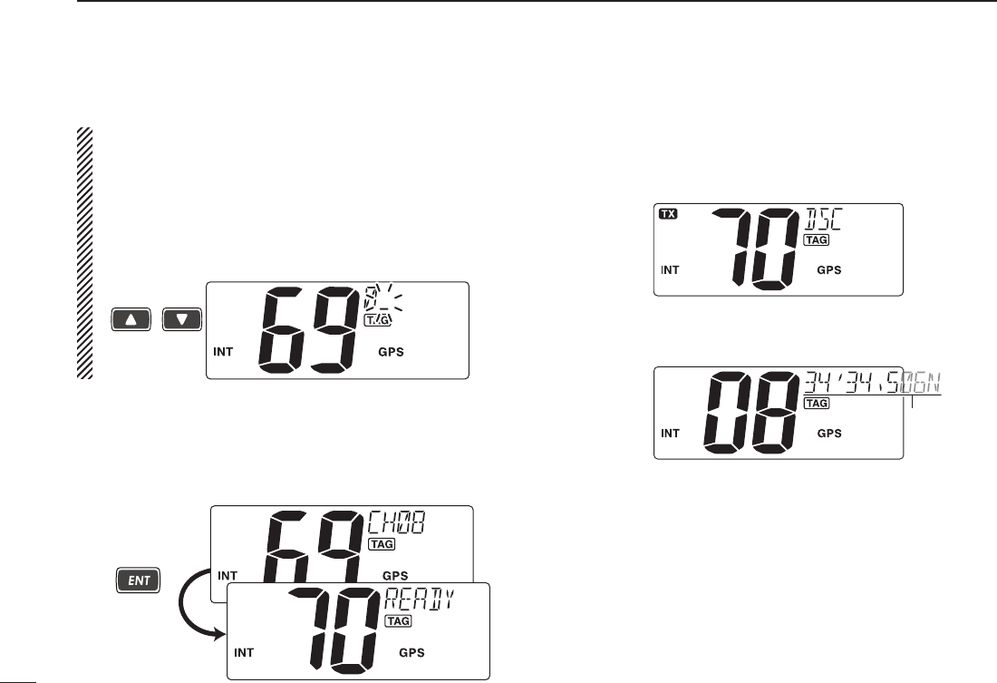
r Push [Y] or [Z] to select a desired intership channel,
then push [ENT].
•Intershipchannelsarealreadypresetintothetransceiverin
preferred order.
•Afterpushing[ENT], Channel 70 is automatically selected and
“READY” appears at the channel comment indicator.
Push
23
6
DSC OPERATION
New2001
6
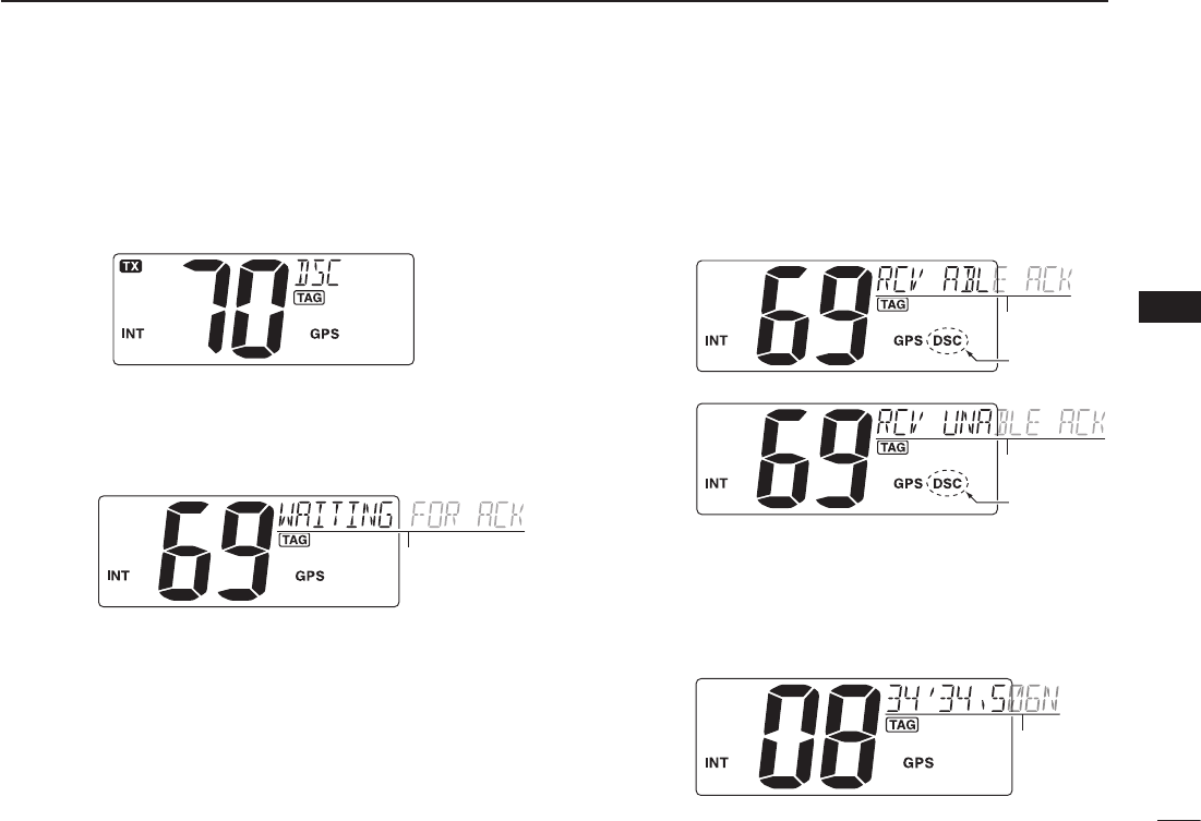
t Push [ENT] to transmit the Individual call.
•IfChannel70isbusy,thetransceiverstandsbyuntilthechan-
nel becomes clear.
•Routinecategoryonlyisavailable.
Transmitting
y Stands by on the operated channel (before entering the
DSC menu in step q), until an acknowledgement call is
received.
•“WAITINGFORACK”scrollsatthechannelcommentindicator.
Scrolls
u When the acknowledgement is received, “DSC” appears
and “RCV ABLE ACK” or “RCV UNABLE ACK” scrolls at
the channel comment indicator with beeps.
•Push[CLR] to stop the beep.
‘Able to comply’ is received.
‘Unable to comply’ is received.
Scrolls
Scrolls
Appears
Appears
i
Push [ENT] to move to the intership channel, specified in
step r, then hold down [PTT] to communicate your message
to the responding ship when ‘Able to comply’ is received.
•Push[CLR] to return to the normal operation condition.
•When‘Unabletocomply’isreceived,push[ENT] to return to
the normal operation condition.
Scrolls
After receiving ‘ABLE’ ACK
24
6DSC OPERATION
New2001
n Transmitting DSC calls (Continued)
D
Transmitting an Individual acknowledgement
When receiving an Individual call, you can transmit an ac-
knowledgement (‘Able to comply’ or ‘Unable to comply’) by
using the on screen prompts (Quick ACK.) Also, you can
send an acknowledgement through the menu system (Man-
ual ACK.)
Quick ACK:
➥ After an Individual call is received, push [CLR] to stop
beep, then push [ENT]. (Go to step r as below.)
Manual ACK:
q Push [MENU] to enter the DSC menu.
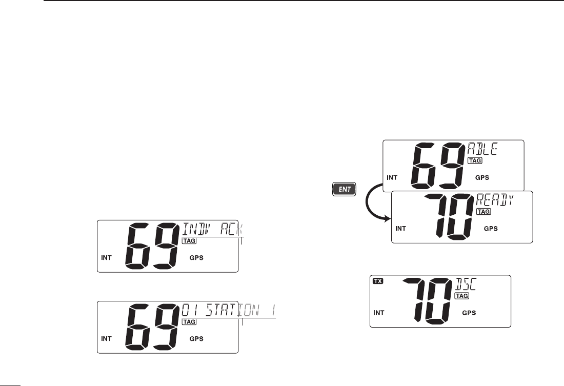
w Push [Y] or [Z] to select “INDV ACK,” the push [ENT].
•“INDV ACK” item appears after receiving an Individual call.
Scrolls
e Push [Y] or [Z] to select a desired individual address,
then push [ENT].
Scrolls
r Push [Y] or [Z] to select the acknowledgement “ABLE”
or “UNABLE,” then push [ENT].
•“UNABLE” selection will transmit the reason “No Reason
Given”.
•Afterpushing[ENT], Channel 70 is automatically selected and
“READY” appears at the channel comment indicator.
‘ABLE’ is
selected.
Push
t Push [ENT] to transmit the acknowledgement call to the
selected station.
Transmitting
25
6
DSC OPERATION
New2001
6
y After the Individual acknowledgement call has been trans-
mitted, the specified channel (specified by the calling sta-
tion) is selected automatically when “ABLE” is selected,
or returns to the previous condition (before entering the
DSC menu) when “UNABLE” is selected in step e.
Scrolls
After transmitting ‘ABLE’ ACK
D Transmitting a Group call
The Group call function allows you to transmit a DSC signal
to a specific group only.
q Push [MENU] to enter the DSC menu.
w Push [Y] or [Z] to select “GROUP,” then push [ENT].
e Push [Y] or [Z] to select a desired pre-programmed
Group address or “MANUAL INPUT,” then push [ENT].
•TheIDcodeforthegroupcanbesetinadvance.(p.15)
•When“MANUALINPUT”isselected,setthe8-digitMMSIID
code for the group you wish to call with [Y] or [Z]. (See About
Manual Inputting as at right.)
Scrolls
☞ Continue to the next page
26
6DSC OPERATION
New2001
n Transmitting DSC calls
D Transmitting a Group call (Continued)
About Manual Inputting:
Push [Y] or [Z] to input the 8-digit Group ID, then push
[ENT].
•Push[CH/WX] or [16] to move the cursor forward or backward,
respectively.
•Push[CLR] to cancel and exit the condition.
•1stdigit‘0’isxedforaGroupID.
•Gotothenextstepafterpushing[ENT].
Push
/
r Push [Y] or [Z] to select a desired intership channel,
then push [ENT].
•Intershipchannelsarealreadypresetintothetransceiverin
recommending order.
•Afterpushing[ENT], Channel 70 is automatically selected and
“READY” appears at the channel comment indicator.
Push
t Push [ENT] to transmit the Group call.
•IfChannel70isbusy,thetransceiverstandsbyuntilthechan-
nel becomes clear.
•Routinecategoryonlyisavailable.
Transmitting
y After the Group call has been transmitted, the specified
channel (in step r) is automatically selected.
Scrolls
After transmitting ‘ABLE’ ACK
u Hold down [PTT] to announce your message to the re-
sponding ship.
27
6
DSC OPERATION
New2001
6
D Transmitting an All Ships call
Large ships use Channel 70 as their ‘listening channel.’
When you want to announce a message to these ships
within range, use the ‘All Ships call’ function.
q Push [MENU] to enter the DSC menu.
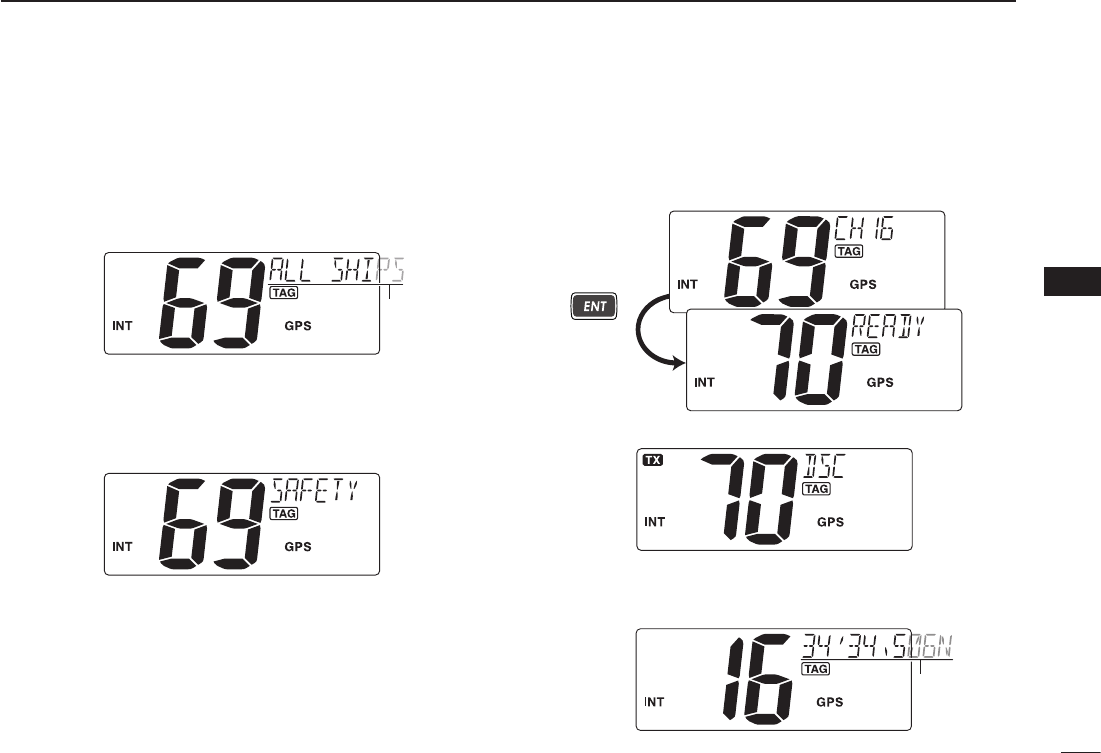
w Push [Y] or [Z] to select “ALL SHIPS,” then push [ENT].
Scrolls
e Push [Y] or [Z] to select the desired category, then push
[ENT].
•Outputpowerof‘Routine’categoryis1W(lowpower)only.
•Theselectablecategorymaydifferaccordingtothepro-
grammed setting. Ask your dealer for the available categories.
r Push [Y] or [Z] to select a desired ITU channel, then
push [ENT].
•Afterpushing[ENT], Channel 70 is automatically selected and
“READY” appears at the channel comment indicator.
Push
t Push [ENT] to transmit the All Ships call.
Transmitting
y After the All Ships call has been transmitted, the specified
channel (in step r) is selected automatically.
Scrolls
28
6DSC OPERATION
New2001
n Transmitting DSC calls (Continued)
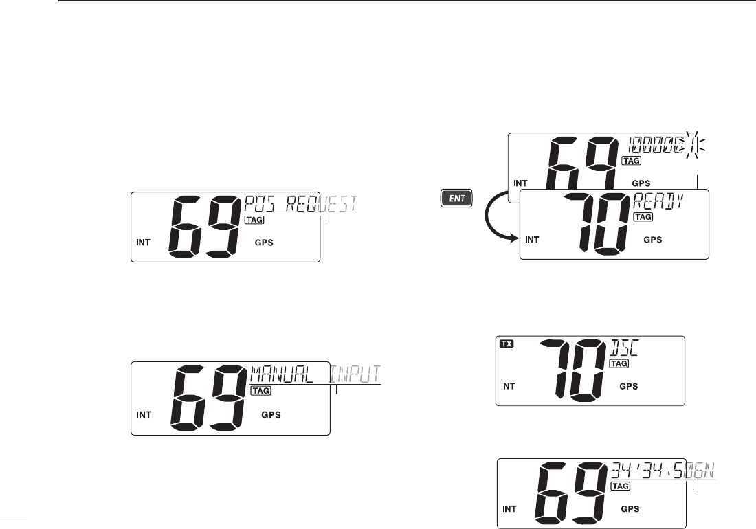
D Transmitting a Position Request call
Transmit a Position Request call when you want to know a
specified ship’s current position, etc.
q Push [MENU] to enter the DSC menu.
w Push [Y] or [Z] to select “POS REQUEST,” then push
[ENT].
Scrolls
e Push [Y] or [Z] to select a desired pre-programmed Indi-
vidual address or “MANUAL INPUT,” then push [ENT].
•TheIDcodefortheindividualcanbesetinadvance.(p.14)
•When“MANUALINPUT”isselected,setthe9-digitMMSIID
code for the individual you wish to call with [Y] or [Z]. (See
About Manual Inputting; p. 22)
Scrolls
r After step e, Channel 70 is automatically selected and
“READY” appears at the channel comment indicator.
Push
The last digit
*This illustration describes with “MANUAL INPUT”
selection in step e.
t Push [ENT] to transmit the Position Request call.
•IfChannel70isbusy,thetransceiverstandsbyuntilthechan-
nel becomes clear.
Transmitting
y After the Position Request call has been transmitted, re-
turns to the normal operation.
Scrolls
29
6
DSC OPERATION
New2001
6
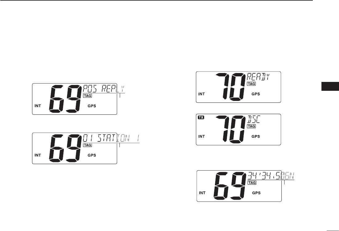
D Transmitting a Position Reply call
Transmit a Position Reply call when a Position Request call
is received.
q Push [MENU] to enter the DSC menu.
w Push [Y] or [Z] to select “POS REPLY,” then push [ENT].
•“POSREPLY”itemappearsafterreceivingaPositionRequest
call.
Scrolls
e Push [Y] or [Z] to select a desired individual address,
then push [ENT].
Scrolls
r The position information appears. Input your position data
(latitude and longitude) directly with [Y] or [Z]. (p. 17)
t After editing the position data, push [ENT] to set. Then
edit the current UTC time directly with [Y] or [Z] (p. 17),
then push [ENT].
•Afterpushing[ENT], Channel 70 is automatically selected and
“READY” appears at the channel comment indicator.
y Push [ENT] to transmit the Position Reply call.
Transmitting
u After the Position Reply call has been transmitted, returns
to the normal operation.
Scrolls
30
6DSC OPERATION
New2001
n Transmitting DSC calls (Continued)
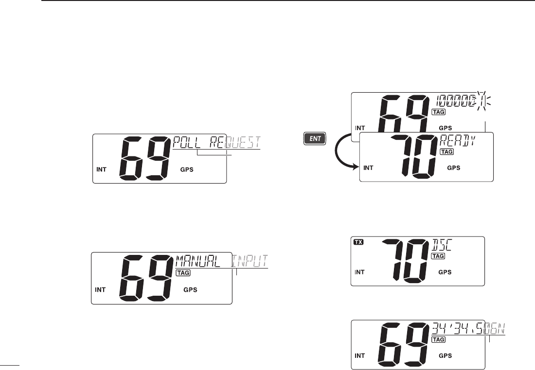
D Transmitting a Polling Request call
Transmit a Polling Request call when you want to know a
specific ship is in the communication area, etc.
q Push [MENU] to enter the DSC menu.
w Push [Y] or [Z] to select “POLL REQUEST,” then push
[ENT].
Scrolls
e Push [Y] or [Z] to select a desired pre-programmed Indi-
vidual address or “MANUAL INPUT,” then push [ENT].
•TheIDcodefortheindividualcanbesetinadvance.(p.14)
•When“MANUALINPUT”isselected,setthe9-digitMMSIID
code for the individual you wish to call with [Y] or [Z]. (See
About Manual Inputting; p. 22)
Scrolls
r After step e, Channel 70 is automatically selected and
“READY” appears at the channel comment indicator.
Push
The last digit
*This illustration describes with “MANUAL INPUT”
selection in step e.
t Push [ENT] to transmit the Polling Request call.
•IfChannel70isbusy,thetransceiverstandsbyuntilthechan-
nel becomes clear.
Transmitting
y After the Polling Request call has been transmitted, re-
turns to the normal operation.
Scrolls
31
6
DSC OPERATION
New2001
1
2
3
4
5
6
7
8
9
10
11
12
13
14
15
16
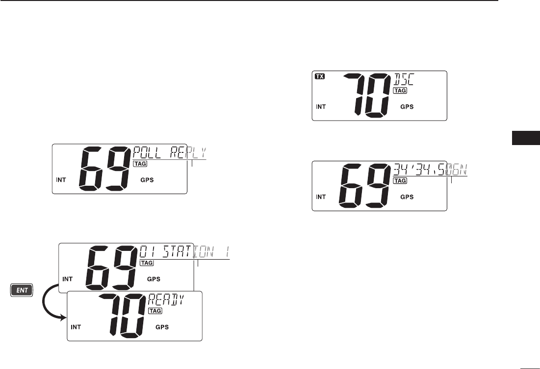
D Transmitting a Polling Reply call
Transmit a Polling Reply call when a Polling Request call is
received.
q Push [MENU] to enter the DSC menu.
w Push [Y] or [Z] to select “POLL REPLY,” then push
[ENT].
•“POLLREPLY”itemappearsafterreceivingaPollingRequest
call.
Scrolls
e Push [Y] or [Z] to select a desired individual address,
then push [ENT].
•Afterpushing[ENT], Channel 70 is automatically selected and
“READY” appears at the channel comment indicator.
Scrolls
Push
r Push [ENT] to transmit the Polling Reply call.
Transmitting
t After the Polling Reply call has been transmitted, returns
to the normal operation.
Scrolls
32
6DSC OPERATION
New2001
n Transmitting DSC calls (Continued)
D Test Call
Testing on the exclusive DSC distress and safety calling
channels should be avoided as much as possible by using
other methods. When testing on the distress/safety chan-
nel is unavoidable, it should be indicated that these are test
transmissions.
Normally the test call would require no further communica-
tions between the two stations involved.
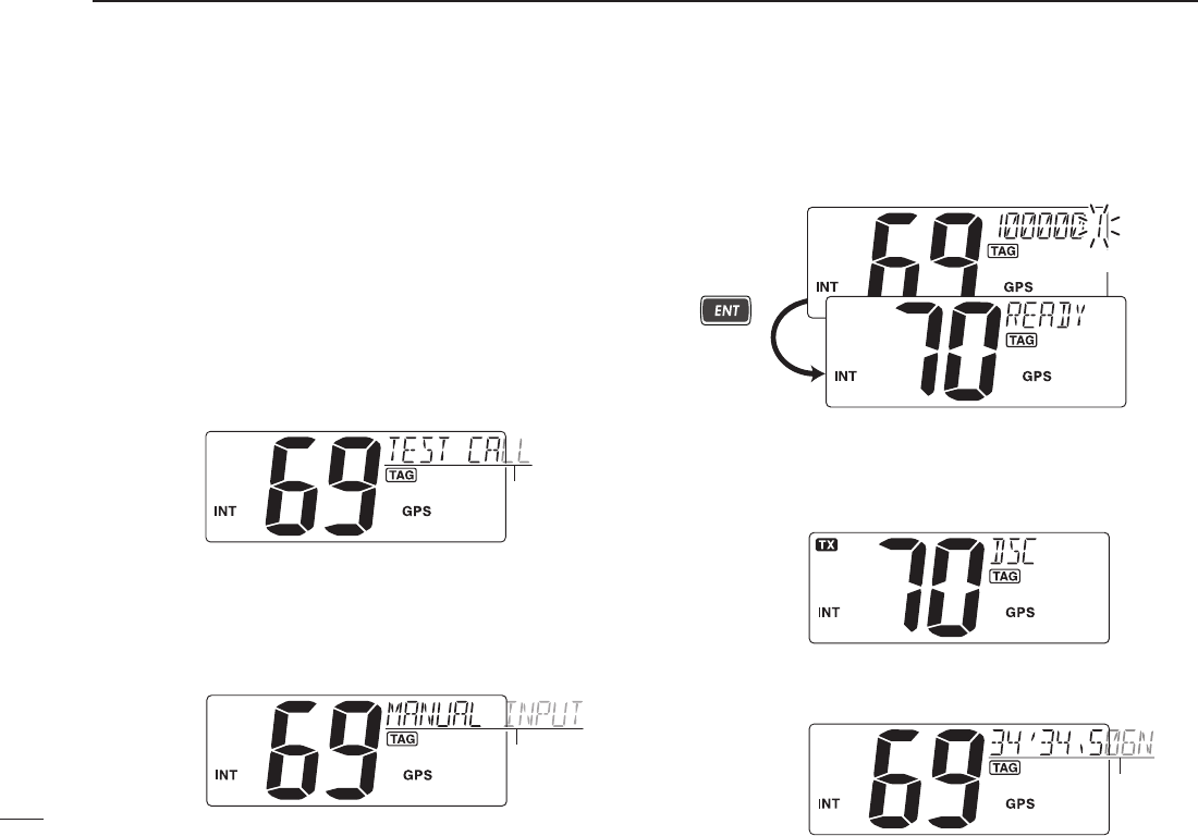
q Push [MENU] to enter the DSC menu.
w Push [s] or [t] to select “TEST CALL,” and then push
[ENT].
Scrolls
e Push [Y] or [Z] to select a desired pre-programmed Indi-
vidual address or “MANUAL INPUT,” then push [ENT].
•TheIDcodefortheindividualcanbesetinadvance.(p.14)
•When“MANUALINPUT”isselected,setthe9-digitMMSIID
code for the individual you wish to call with [Y] or [Z]. (See
About Manual Inputting; p. 22)
Scrolls
r After step e, Channel 70 is automatically selected and
“READY” appears at the channel comment indicator.
Push
The last digit
*This illustration describes with “MANUAL INPUT”
selection in step e.
r Push [ENT] to transmit the Test call.
•IfChannel70isbusy,thetransceiverstandsbyuntilthechan-
nel becomes clear.
Transmitting
t After the Test call has been transmitted, returns to the
normal operation.
Scrolls
33
6
DSC OPERATION
New2001
1
2
3
4
5
6
7
8
9
10
11
12
13
14
15
16
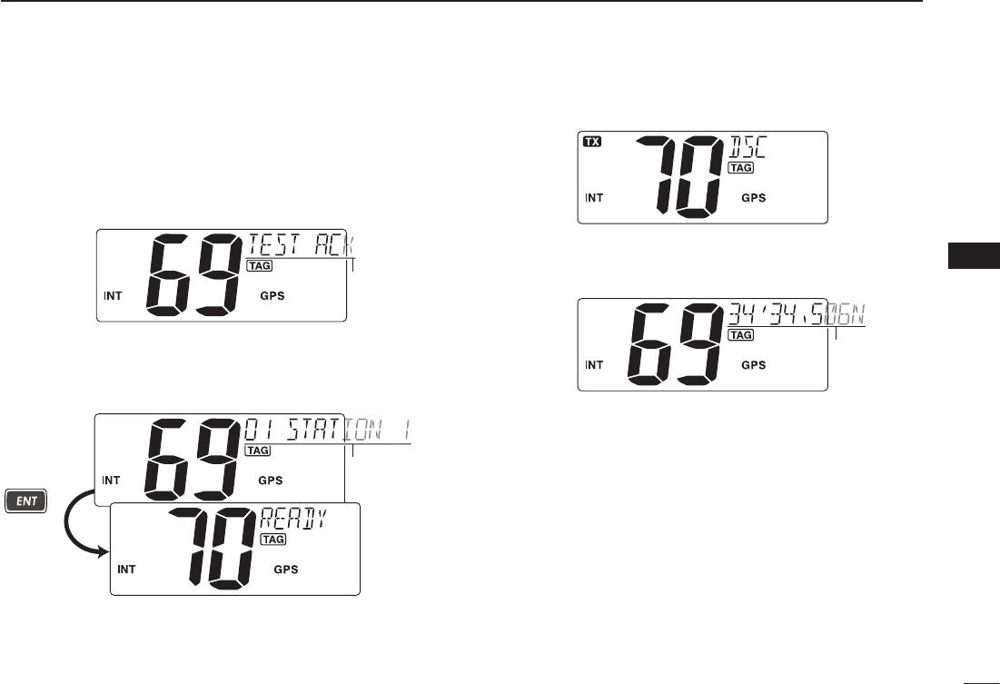
D Transmitting a Test Ack call
Transmit a Test Acknowledgement call when a Test call is
received.
q Push [MENU] to enter the DSC menu.
w Push [Y] or [Z] to select “TEST ACK,” then push [ENT].
•“TESTACK”itemappearsafterreceivingaPollingRequestcall.
Scrolls
e Push [Y] or [Z] to select a desired individual address,
then push [ENT].
•Afterpushing[ENT], Channel 70 is automatically selected and
“READY” appears at the channel comment indicator.
Scrolls
Push
r Push [ENT] to transmit the Test Ack call.
Transmitting
t After the Test Ack call has been transmitted, returns to
the normal operation.
Scrolls
34
6DSC OPERATION
New2001
n Receiving DSC calls
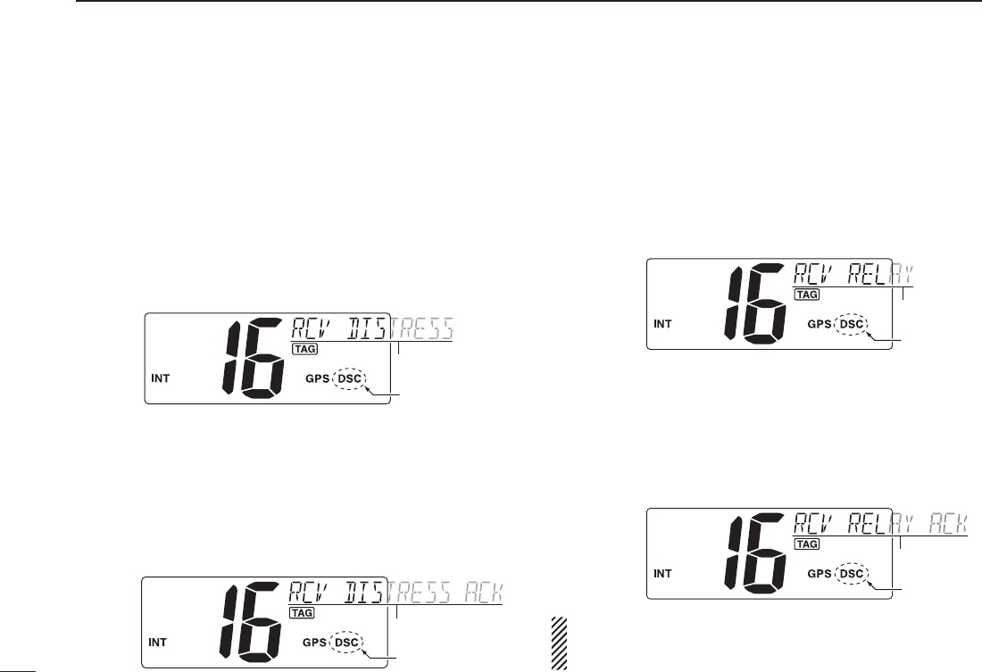
D Receiving a Distress call
While monitoring Channel 70 and a Distress call is received:
➥ The emergency alarm sounds for 2 minutes.
•Pushanykeytostopthealarm.
➥ “ DSC” appears and “RCV DISTRESS” scrolls at the chan-
nel comment indicator, then Channel 16 is selected auto-
matically.
➥ Continue monitoring Channel 16 as a coast station may
require assistance.
Scrolls
Appears
D Receiving a Distress Acknowledgement
While monitoring Channel 70 and a Distress acknowledge-
ment to other ship is received:
➥ The emergency alarm sounds for 2 minutes.
•Pushanykeytostopthealarm.
➥“DSC” appears and “RCV DISTRESS ACK” scrolls at the
channel comment indicator, then Channel 16 is selected
automatically.
Scrolls
Appears
D Receiving a Distress Relay call
While monitoring Channel 70 and a Distress Relay is received:
➥ The emergency alarm sounds for 2 minutes.
•Pushanykeytostopthealarm.
➥ “ DSC” appears and “RCV RELAY” scrolls at the channel com-
ment indicator, then Channel 16 is selected automatically.
Scrolls
Appears
D
Receiving a Distress Relay Acknowledgement
While monitoring Channel 70 and a Distress Relay acknowl-
edgement is received:
➥ The emergency alarm sounds for 2 minutes.
•Pushanykeytostopthealarm.
➥ “ DSC” appears and “RCV RELAY ACK” scrolls at the channel
comment indicator, then Channel 16 is selected automatically.
Scrolls
Appears
NOTE: The alarm sounds when duplicate distress relay
or distress relay acknowledgement call for individual is
received within 1 hour.
35
6
DSC OPERATION
New2001
1
2
3
4
5
6
7
8
9
10
11
12
13
14
15
16
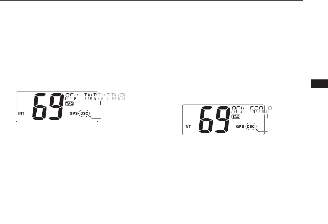
D Receiving an Individual call
While monitoring Channel 70 and an Individual call is received:
➥ The emergency alarm or beeps sound for 2 minutes de-
pending on the received category.
•Push[CLR] to stop the alarm or beeps.
➥ “ DSC” appears and “RCV INDIVIDUAL” scrolls at the chan-
nel comment indicator.
Scrolls
Appears
➥ Push [ENT] to reply the call and select the channel speci-
fied by the calling station for voice communication (de-
pending on your replying condition. See p, 23 for Individual
acknowledgement call procedure for details.); push [CLR]
other key to ignore the call.
D Receiving a Group call
While monitoring Channel 70 and a Group call is received:
➥ The emergency alarm or beeps sound for 2 minutes de-
pending on the received category.
•Push[CLR] to stop the alarm or beeps.
➥ “ DSC” appears and “RCV GROUP” scrolls at the channel
comment indicator.
➥
Push [ENT] to select the channel specified by the calling sta-
tion for voice communication; push [CLR] to ignore the call.
Scrolls
Appears
36
6DSC OPERATION
New2001
n Receiving DSC calls (Continued)
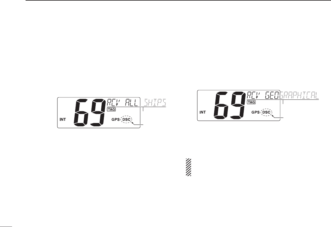
D Receiving an All Ships call
While monitoring Channel 70 and an All Ships call is received:
➥ The emergency alarm sounds for 2 minutes depending
on the received categories.
•Push[CLR] to stop the alarm or beeps.
➥ “ DSC” appears and “RCV ALL SHIPS” scrolls at the chan-
nel comment indicator.
➥ Push [ENT] to monitor Channel 16 for an announcement
from the calling vessel, push [CLR] to ignore the call.
Scrolls
Appears
D Receiving a Geographical Area call
While monitoring Channel 70 and a Geographical Area call
(for the area you are in) is received:
➥ The emergency alarm or beeps sound for 2 minutes de-
pending on the received category.
•Push[CLR] to stop the alarm or beeps.
➥ “ DSC” appears and “RCV GEOGRAPHICAL” scrolls at
the channel comment indicator.
Scrolls
Appears
➥
Push [ENT] to select the channel specified by the calling sta-
tion for voice communication; push [CLR] to ignore the call.
➥ Monitor the selected channel for an announcement from
the calling station.
When no GPS receiver is connected or if there is a prob-
lem with the connected receiver, all Geographical Area
calls are received, regardless of your position.

37
6
DSC OPERATION
New2001
1
2
3
4
5
6
7
8
9
10
11
12
13
14
15
16
D Receiving a Position Request call
While monitoring Channel 70 and a Position Request call is
received:
➥ “ DSC” appears and “RCV POS REQUEST” scrolls at the
channel comment indicator.
➥ The beeps sound for 2 minutes.
•Push[CLR] to stop the beeps.
➥
Push [ENT] to reply to the call; push [CLR] to ignore the call.
Scrolls
Appears
D Receiving a Polling Request call
While monitoring Channel 70 and a Polling Request call is
received:
➥ “ DSC” appears and “RCV POLL REQUEST” scrolls at the
channel comment indicator.
➥ The beeps sound for 2 minutes.
•Push[CLR] to stop the beeps.
➥
Push [ENT] to reply to the call; push [CLR] to ignore the call.
Scrolls
Appears
D Receiving a Position Reply call
While monitoring Channel 70 and a Position Request Reply
call is received:
➥“DSC” and “POS REPLY” appear in the display.
•The‘Latitude’and‘Longitude’fromthecalledstationisdis-
played and scrolled at the channel comment indicator in order
of Latitude co-ordinates and then Longitude co-ordinates.
•“NOPOSITION”scrollsatthechannelcommentindicatorwhen
no position information is received.
➥ The beeps sound for 2 minutes.
•Push[CLR] to stop the beeps.
Scrolls
Appears
D Receiving a Polling Reply call
While monitoring Channel 70 and a Polling Reply call is re-
ceived:
➥ “ DSC” appears and “RCV POLL REPLY” scrolls at the
channel comment indicator.
➥ The beeps sound for 2 minutes.
•Push[CLR] to stop the beeps.
Scrolls
Appears
38
6DSC OPERATION
New2001
n Receiving DSC calls (Continued)
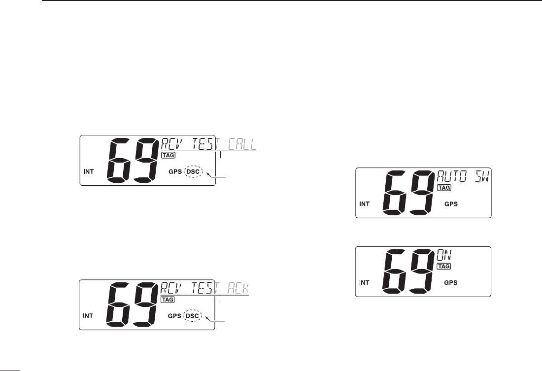
D Receiving a Test call
While monitoring Channel 70 and a Test call is received:
➥ “ DSC” appears and “RCV TEST CALL” scrolls at the
channel comment indicator.
➥ The beeps sound for 2 minutes.
•Push[CLR] to stop the beeps.
➥
Push [ENT] to reply to the call; push [CLR] to ignore the call.
Scrolls
Appears
D Receiving a Test Acknowledgement call
While monitoring Channel 70 and a Test Acknowledgement
call is received:
➥ “ DSC” appears and “RCV TEST ACK” scrolls at the chan-
nel comment indicator.
➥ The beeps sound for 2 minutes.
•Push[CLR] to stop the beeps.
➥
Push [ENT] to reply to the call; push [CLR] to ignore the call.
Scrolls
Appears
D Auto switch function
By regulation, after receiving a Distress call, the transceiver
basically switches the operating channel to CH 16. However,
when this setting is set to “OFF,” the function enables the
transceiver to remain on the operating channel even after
receiving a Distress call.
q Push [MENU] to enter the DSC menu.
w Push [s] or [t] to select “AUTO SW,” and push [ENT].
e Push [s] or [t] to select the Auto switch “ON” or “OFF.”
•Push[CLR] to cancel and exit the setting.
OFF : The transceiver remains on the operating channel
even after receiving a Distress call.
ON : The transceiver automatically switches the
operating channel to CH16 after receiving a
Distress call. (default)
r Push [ENT] to set and exits the setting.
39
6
DSC OPERATION
New2001
1
2
3
4
5
6
7
8
9
10
11
12
13
14
15
16
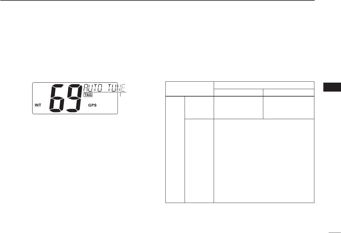
D Auto tune timer
This is the amount of time after receiving a Distress call
before the transceiver switches to CH 16.
q Push [MENU] to enter the DSC menu.
w Push [s] or [t] to select “AUTO TUNE,” and push [ENT].
Scrolls
e Push [s] or [t] to set the Auto tune timer period to be-
tween 10 and 600 seconds (1 second steps) or turn OFF.
•Push[CLR] to cancel and exit the setting.
OFF : Turns OFF the Auto Tune timer.
10 to 600 : After receiving a Distress call, the transceiver
remains on the operating channel for the
programmed time period between 10 and 600
seconds, and then automatically switches to
CH16. (default : 30)
Within the programmed timer period, the
following action can be taken:
- When the [ENT] key is pushed, immediately
switches to CH 16.
| - When the [CLR] key is pushed, the Auto
tune timer is cancelled and the transceiver
remains on the operating channelled.
r Push [ENT] to set and exits the setting.
The action of the transceiver may differ, depending on the
combination of the Auto Switch function and the Auto Tune
timer settings.
•CombinedoperationwhenreceivingaDSCcall:
Auto Switch
OFF ON
Auto
tune
OFF The transceiver
remains on the
operating channel.
The transceiver
automatically
switches to CH 16.
ON
(10 to 600)
The transceiver remains on the
operating channel for the programmed
time period, and then automatically
switches to CH16.
Within the programmed timer period,
the following action can be taken:
•When th e [ENT] key is pushed,
immediately switches to CH 16.
•When the [CLR] key is pushed,
remains on the operating channel
since the Auto Tuner timer is
cancelled.
40
6DSC OPERATION
New2001
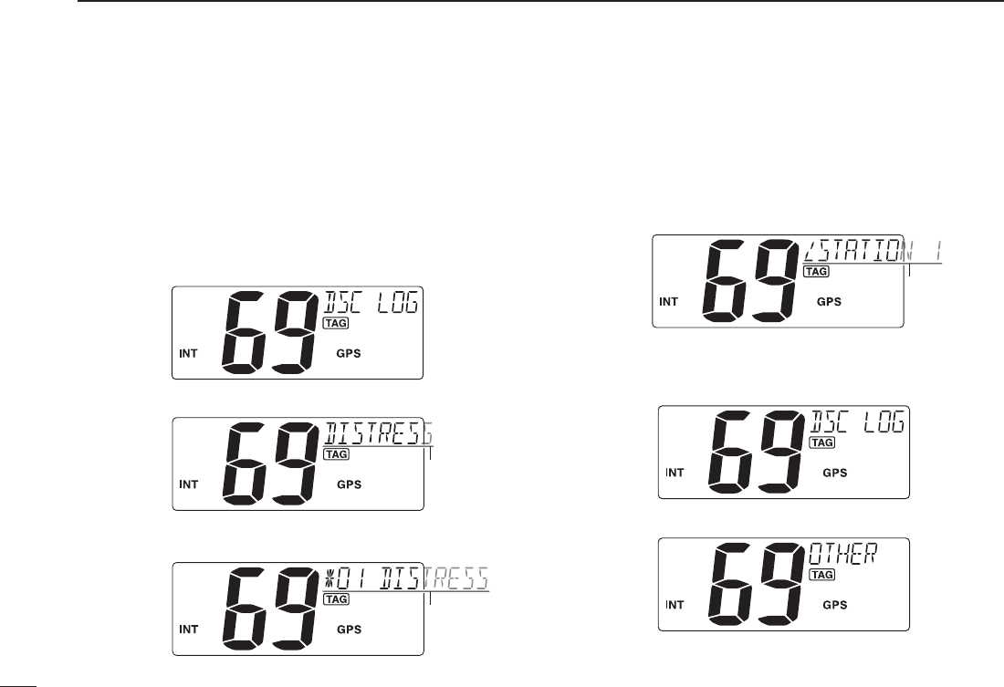
n Received messages
The transceiver automatically stores up to 20 distress mes-
sages and 20 other messages. The messages can be used
as an assistance to the logbook.
D Distress message
q Push [MENU] to enter the DSC menu.
w Push [s] or [t] to select “DSC LOG,” and push [ENT].
e Push [s] or [t] to select “DISTRESS,” push [ENT].
Scrolls
r
Push [s] or [t] to select a desired message, push [ENT].
•“M” appears when the unread messages is selected.
Scrolls
t The message information scrolls.
•Thestoredmessagehasvariousinformation.
•Push[CLR] to exit the condition.
•Holddown[CLR] for 1 second to delete the displayed message
and returns to DSC menu.
Scrolls
D Other messages
q Push [MENU] to enter the DSC menu.
w Push [s] or [t] to select “DSC LOG,” and push [ENT].
e Push [s] or [t] to select “OTHER,” push [ENT].

41
6
DSC OPERATION
New2001
1
2
3
4
5
6
7
8
9
10
11
12
13
14
15
16
r
Push [s] or [t] to select a desired message, push [ENT].
•“M” appears when the unread messages is selected.
Scrolls
t The message information scrolls.
•Thestoredmessagehasvariousinformation.
•Push[CLR] to exit the condition.
•Holddown[CLR] for 1 second to delete the displayed message
and returns to DSC menu.
Scrolls
42
6DSC OPERATION
New2001
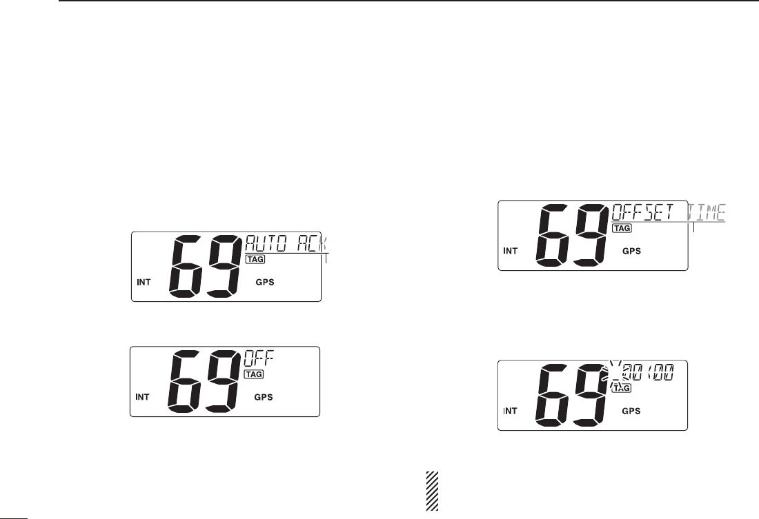
n Automatic acknowledgement
This item sets the automatic acknowledgement function ON
or OFF.
When a position request or polling request call is received,
transceiver automatically transmits a position request reply
or polling reply call, respectively.
q Push [MENU] to enter the DSC menu.
w Push [s] or [t] to select “AUTO ACK,” and push [ENT].
Scrolls
e Push [s] or [t]
to turn the
automatic acknowledgement
function ON or OFF
.
r Push [ENT] to set the condition.
•Push[CLR] to cancel and exit the condition.
n Offset time
This item sets the offset time from the UTC (Universal Time
Coordinated) time.
q Push [MENU] to enter the DSC menu.
w Push [s] or [t] to select “OFFSET TIME,” and push
[ENT].
Scrolls
e Set the offset time from the UTC (Universal Time Coordi-
nated) time using [s] or [t].
•Push[CH/WX] or [16] to move the cursor forward or backward,
respectively.
•Push[CLR] to cancel and exit the condition.
r Push [ENT] to program and to exit the condition.
The local time indication is not available when the GPS
receiver (sentence formatter RMC) is connected, the
transceiver’s display indicates UTC time only.

43
6
DSC OPERATION
New2001
1
2
3
4
5
6
7
8
9
10
11
12
13
14
15
16
44
New2001New2001
SET MODE
7
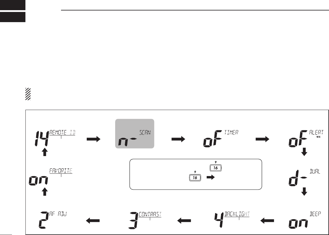
n Set mode programming
Set mode is used to change the conditions of the trans-
ceiver’s functions: Scan type, Scan resume timer, Dual/Tri-
watch, Operation beep, LCD backlight, LCD contrast, AF
level adjustment and Favorite channel.
Available functions may differ depending on dealer set-
ting.
q Turn power OFF.
w While pushing [16], turn ON the power to enter the Set mode.
•“SCAN”appearsatthechannelcommentindicator.
e After the display appears, release [16].
r Push [16] to select a desired item, if necessary.
t Push [Y] or [Z] to select the desired setting of the item.
y Turn power OFF, then ON again to exit the Set mode.
D SET MODE CONSTRUCTION
• Weather alert
• Dual/Tri-watch
• Scan resume
timer
• Operation beep
• AF level
adjustment
• LCD Contrast • LCD Backlight
• Remote ID
• Favorite channel
• Scan type
, turn power ON.• To enter Set mode: While pushing
• To exit Set mode: Tu rn power OFF, then ON again.
• To select the item: Push . ( )
Starting item
Scrolls
Scrolls
Scrolls
Scrolls

New2001
45
7
SET MODE
New2001
1
2
3
4
5
6
7
8
9
10
11
12
13
14
15
16
n Set mode items
D Scan type
The transceiver has two scan types: Normal scan and Prior-
ity scan. Normal scan searches all TAG channels in the se-
lected channel group. Priority scan searches all TAG chan-
nels in sequence while monitoring Channel 16.
Normal scan (default) Priority scan
D Scan resume timer
The scan resume timer can be selected as a pause (OFF) or
timer scan (ON).
ON : The scan pauses 5 seconds and resumes even if a
signal has been received on any other channel than
Channel 16.
OFF : The scan pauses until the signal disappears.
Scan timer OFF (default) Scan timer ON
D Weather alert
A NOAA broadcast station transmits a weather alert tone
before important weather information. When the Weather
Alert function is turned ON, the transceiver detects the alert,
then the “WX ALT” indicator blinks until the transceiver is
operated. The previously selected (used) weather channel is
checked any time during standby or while scanning.
•“WX ALT” appears instead of “WX” indication when the function is
set ON.
Weather alert OFF (default)
Weather alert ON
Appears
Appears
New2001
46
7SET MODE
New2001
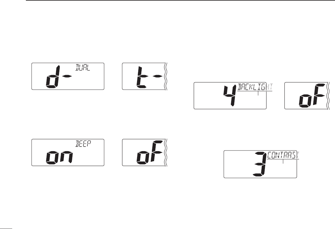
D Dual/Tri-watch
This item can be selected as Dualwatch or Tri-watch. (p. 12)
Dualwatch (default) Tr i-watch
D Operation beep
You can select the silent operation by turning beep tones
OFF or you can have confirmation beeps sound at the push
of a key by turning beep tones ON.
Beep tone ON (default) Beep tone OFF
D LCD backlight
The LCD backlight brightness can be adjusted from OFF, 1
(dark) to 4 (bright.)
LCD backlight is also adjustable via [SCAN•TAG] key. (p. 9)
•“BACKLIGHT” scrolls at the channel comment indicator.
LCD backlight level 4 (default) LCD backlight OFF
Scrolls
D LCD contrast
The LCD contrast can be adjustable in 4 levels. 1 is the low-
est contrast, and 4 is the highest contrast.
•“CONTRAST” scrolls at the channel comment indicator.
LCD contrast level 3 (default)
Scrolls

New2001New2001
47
7
SET MODE
New2001
1
2
3
4
5
6
7
8
9
10
11
12
13
14
15
16
D AF level adjustment
When turning the power ON, a beep is emitted to adjust the
audio frequency level via [VOL].
Select the time period for the beep emission from 2, 5, 8, 10
(seconds) or OFF.
AF level 2 (default) AF level OFF
D Favorite channel
This item sets the Favorite channel function ON or OFF.
The favorite channels are set by the TAG channel setting.
(p. 11)
•“FAVORITE” scrolls at the channel comment indicator.
ON : [Y]/[Z] keys on the microphone select the favorite
channels in the selected channel group in sequence
when pushed.
OFF :
[Y]/[Z] keys on the microphone select all channels in
the selected channel group in sequence when pushed.
Favorite channel ON (default) Favorite channel OFF
Scrolls
D Remote ID
Set a Remote ID number between 01 and 69.
The Remote ID is included in the sentence of the format for
the Icom own NMEA.
Remote ID 14 (default) Remote ID 69
Scrolls
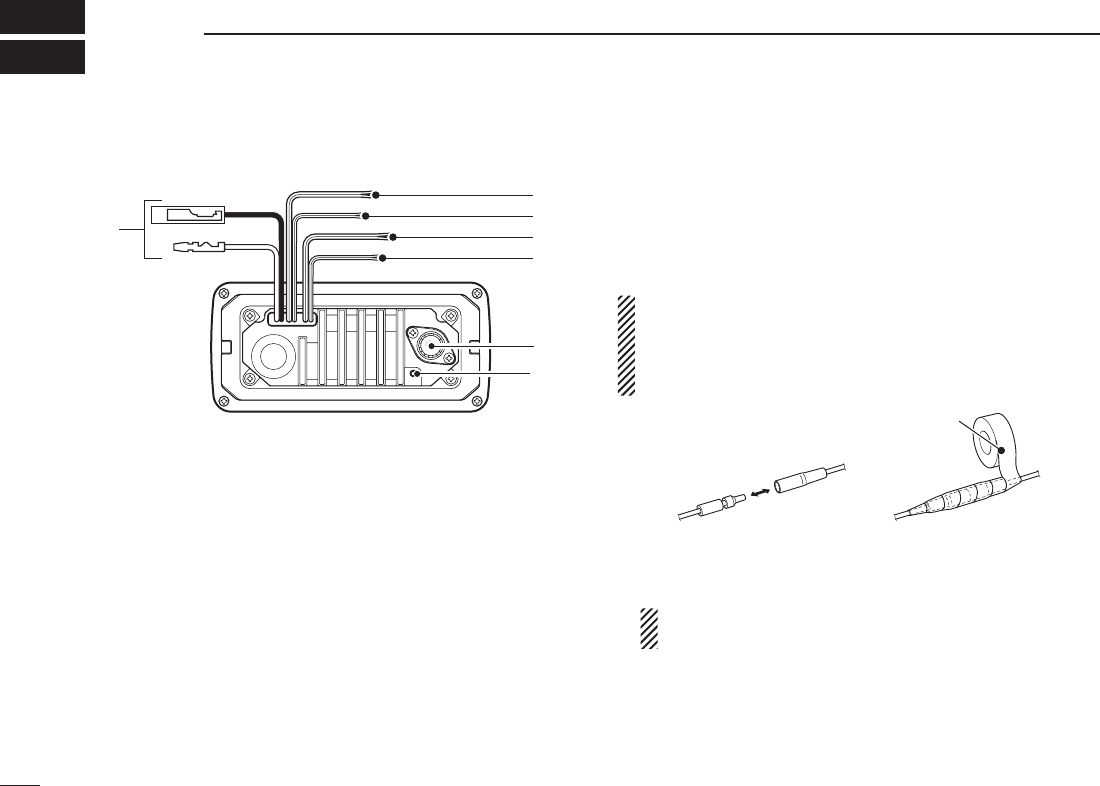
New2001
n Connections
q
y
u
w
e
r
t
q DC POWER CONNECTOR
Connects the supplied DC power cable from this connec-
tor to an external 12 V battery.
w EXTERNAL SPEAKER LEAD (Yellow)
Connects to an external speaker.
e CLONE LEAD (Blue)
Connects to a cloning cable.
r NMEA IN LEAD (Red)
Connects to a GPS receiver for position indication.
•ANMEA0183ver.2.0or3.01(sentenceformattersRMC,GGA,
GNS, GLL) compatible GPS receiver is required. Ask your
dealer about suitable GPS receivers.
t NMEA OUT LEAD (White)
Connects to a PC or navigation equipment (NMEA0183
ver. 3.01 sentence formatters DSC, DSE compatible) for
plotting position data received from other ships.
CAUTION: After connecting the DC power cable, NMEA
IN/OUT leads, external speaker lead (and clone lead),
cover the connector and leads with a rubber vulcanzing
tape as shown below, to prevent water seeping into the
transceiver.
Rubber vulcanizing
tape
y ANTENNA CONNECTOR
Connects a marine VHF antenna with a PL-259 connector
to the transceiver.
CAUTION: Transmitting without an antenna may dam-
age the transceiver.
u GROUND TERMINAL
Connect this terminal to a vessel ground to prevent elec-
trical shocks and interference from other equipment oc-
curring. Use a PH M3 × 6 mm screw (not supplied).
48
New2001
CONNECTIONS AND MAINTENANCE
8
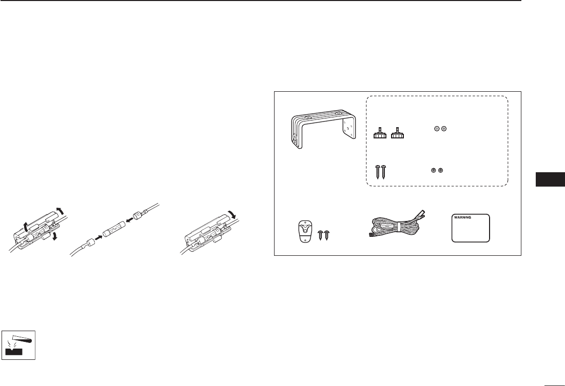
New2001
49
8
CONNECTIONS AND MAINTENANCE
New2001
1
2
3
4
5
6
7
8
9
10
11
12
13
14
15
16
n Antenna
A key element in the performance of any communication
system is the antenna. Ask your dealer about antennas and
the best place to mount them.
n Fuse replacement
One fuse is installed in the supplied DC power cable. If a
fuse blows or the transceiver stops functioning, track down
the source of the problem, if possible, and replace the dam-
aged fuse with a new one of the proper rating.
Fuse rating: 10 A
n Cleaning
If the transceiver becomes dusty or dirty, wipe it clean with a
soft, dry cloth.
AVOID the use of solvents such as benzene or
alcohol, as they may damage transceiver surfaces.
n Supplied accessories
The following accessories are supplied;
Mounting bracket For mounting bracket
DC power cable Warning sticker
Microphone hanger
and screws (3×16)
Knob bolts
Screws (5×20)
Flat washers (M5)
Spring washers (M5)
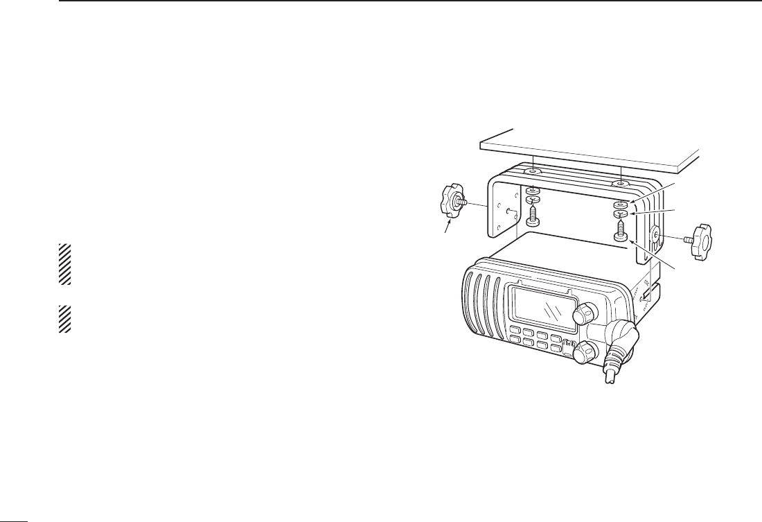
50
8CONNECTIONS AND MAINTENANCE
New2001
n Mounting the transceiver
D Using the supplied mounting bracket
The universal mounting bracket supplied with your trans-
ceiver allows overhead or dashboard mounting.
•Mountthetransceiversecurelywiththe2suppliedscrews
(5 × 20) to a surface which is more than 10 mm thick and
can support more than 5 kg.
•Mountthetransceiversothatthefaceofthetransceiveris
at 90° to your line of sight when operating it.
CAUTION: KEEP the transceiver and microphone at least
1 meter away from your vessel’s magnetic navigation
compass.
NOTE: Check the installation angle; the function display
may not be easy-to-read at some angles.
Spring washer
Flat washer
Screw
(5×20 mm)
EXAMPLE
Knob bolt
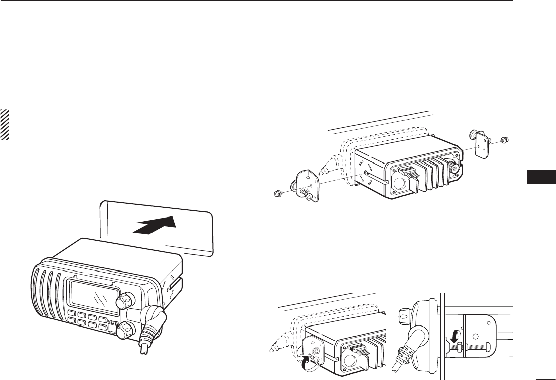
51
8
CONNECTIONS AND MAINTENANCE
New2001
1
2
3
4
5
6
7
8
9
10
11
12
13
14
15
16
n Optional MB-69 installation
An optional MB-69 flush mount is available for mounting
the transceiver to a flat surface such as an instrument panel.
CAUTION: KEEP the transceiver and microphone at least
1 meter away from your vessel’s magnetic navigation
compass.
q Using the template on page 55, carefully cut a hole into
the instrument panel (or wherever you plan to mount the
transceiver.)
w Slide the transceiver through the hole as shown below.
e Attach the clamps on either side of the transceiver with 2
supplied bolts (5 × 8 mm).
•Makesurethattheclampsalignparalleltothetransceiverbody.
r Tighten the end bolts on the clamps (rotate clockwise) so
that the clamps press firmly against the inside of the in-
strument control panel.
t Tighten the locking nuts (rotate counterclockwise) so that
the transceiver is securely mounted in position as below.
y Connect the antenna and power cable, then return the
instrument control panel to its original place.
t
r

New2001
PROBLEM POSSIBLE CAUSE SOLUTION REF.
No sound from speaker.
•Squelchlevelistoohigh.
•Volumelevelistoolow.
•Speakerhasbeenexposedtowater.
p. 7
p. 7
p. 9
•Set[SQL] to the threshold point.
•Set[VOL] to a suitable level.
•Drainwaterfromthespeaker.
The transceiver does
not turn ON.
•Badconnectiontothepowersupply. p. 44•Checktheconnectiontothetransceiver.
Transmitting is impos-
sible, or high power can
not be selected.
•Somechannelsareforlowpowerorre-
ceive only.
•Theoutputpowerissettolow.
pp. 5, 6,
52
p. 7
•Changechannels.
•Push[HI/LO] on the microphone to select
high power.
Scan does not start. •TAGchannelisnotprogrammed. •SetadesiredchannelsasTAGchannels. p. 11
No beeps. •BeeptonesareturnedOFF. •TurnthebeeptoneONintheSetmode. p. 42
Distress call cannot be
transmitted.
•MMSI(DSCselfID)codeisnotpro-
grammed.
•ProgramtheMMSI(DSCselfID)code. p. 13
52
New2001
TROUBLESHOOTING
9

53
10
SPECIFICATIONS AND OPTION
New2001
1
2
3
4
5
6
7
8
9
10
11
12
13
14
15
16
n Specifications
D General
•Frequencycoverage :Tx156.025–157.425MHz
Rx 156.050–163.275 MHz
•Mode :
FM (16K0G3E),
DSC (16K0G2B)
•Channelspacing :25kHz
•Currentdrain(at13.8V) :TXhigh 5.5Amax.
Max. audio 1.5 A max.
•Powersupplyrequirement:13.8VDC(negativeground)
•Frequencystability :±10ppm
•Operatingtemp.range :–20°Cto+60°C
•Antennaimpedance :50ø nominal
•Inputimpedance(MIC) :2kø
•Outputimpedance(audio):4ø
•Dimensions :164(W)× 78(H) × 139.5(D) mm
(Projections not included) 6 15⁄32(W) × 3 1⁄16(H) × 5 15⁄32(D) in
•Weight :Approximately1060g;2.4lb
D Transmitter
•RFoutputpower :25W(High)/1W(Low)
•Modulationsystem :Variablereactancefrequency
modulation
•Max.frequencydeviation :±5.0kHz
•Spuriousemissions :Lessthan70dBc(High)
Less than 60 dBc (Low)
•Adjacentchannelpower :Morethan70dB
•Audioharmonicdistortion:Lessthan10%
(at60%deviation)
•Residualmodulation :Morethan40dB
•Audiofrequencyresponse:+1to–3dBof6dB/octave
range from 300 to 2500 Hz
D Receiver
•Receivesystem :Doubleconversion
superheterodyne
•Sensitivity(12dBSINAD) :–120dBm(typical)
•Squelchsensitivity :Lessthan–115dBm
•Intermodulationrejectionratio :Morethan70dB
•Spuriousresponserejectionratio:Morethan70dB
•Adjacentchannelselectivity :Morethan70dB
•Audiooutputpower :4.5Wtypical
at10%distortion
with a 4 ø load
All stated specifications are subject to change without notice or obligation.
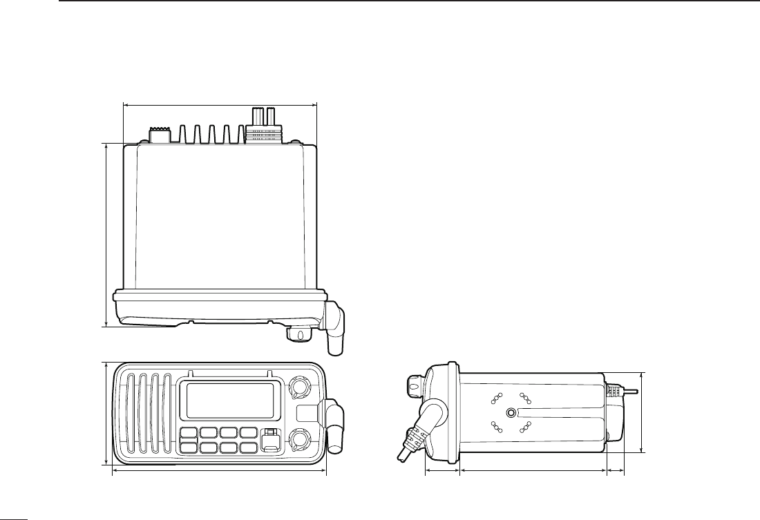
D Dimensions
148
139.578
164 28.3 14.2111.2
60.6
Unit: mm
54
10 SPECIFICATIONS AND OPTION
New2001

55
10
SPECIFICATIONS AND OPTION
New2001
1
2
3
4
5
6
7
8
9
10
11
12
13
14
15
16
n Option
•MB-69 f l u s h m o u n t k i t
For mounting the transceiver to a panel.

56
New2001
CHANNEL LIST
11
Channel number
USA CAN
Transmit
Receive
01 156.050 160.650
01A 156.050 156.050
02 156.100 160.700
03 156.150 160.750
03A 156.150 156.150
156.200 160.800
04A 156.200 156.200
156.250 160.850
05A 05A 156.250 156.250
06 06 156.300 156.300
156.350 160.950
07A 07A 156.350 156.350
08 08 156.400 156.400
09 09 156.450 156.450
10 10 156.500 156.500
11 11 156.550 156.550
12 12 156.600 156.600
13
*2
13
*1
156.650 156.650
14 14 156.700 156.700
15
*2
15
*1
156.750 156.750
16 16 156.800 156.800
17
*1
17
*1
156.850 156.850
156.900 161.500
18A 18A 156.900 156.900
Frequency (MHz)
INT
01
02
03
04
05
06
07
08
09
10
11
12
13
14
15
*1
16
17
18
Channel number Frequency (MHz)
USA CAN
Transmit
Receive
19A 19A 156.950 156.950
20 20
*1
157.000 161.600
21 157.050 161.650
21A 21A 157.050 157.050
157.100 161.700
22A 22A 157.100 157.100
23 157.150 161.750
23A 157.150 157.150
24 24 157.200 161.800
25 25 157.250 161.850
26 26 157.300 161.900
27 27 157.350 161.950
28 28 157.400 162.000
60 156.025 160.625
156.075 160.675
61A 61A 156.075 156.075
156.125 160.725
62A 156.125 156.125
156.175 160.775
63A 156.175 156.175
64 156.225 160.825
INT
20
21
22
23
24
25
26
27
28
60
61
62
63
64
20A 157.000 157.000
Channel number
66A
Frequency (MHz)
66A
*1
USA CAN
Transmit
Receive
64A 64A 156.225 156.225
65A 65A 156.275 156.275
156.325 160.925
67
*2
67 156.375 156.375
68 68 156.425 156.425
69 69 156.475 156.475
70
*3
70
*3
156.525 156.525
71 71 156.575 156.575
72 72 156.625 156.625
73 73 156.675 156.675
74 74 156.725 156.725
77
*1
77
*1
156.875 156.875
156.925 161.525
78A 78A 156.925 156.925
156.975 161.575
79A 79A 156.975 156.975
157.025 161.625
80A 80A 157.025 157.025
157.075 161.675
81A 81A 157.075 157.075
157.125 161.725
82A 82A 157.125 157.125
INT
65A
66
67
68
69
70
*3
71
72
73
74
77
78
79
80
81
82
156.325 156.32566A
Channel number
84A
Frequency (MHz)
USA CAN
Transmit
Receive
83A 83A 157.175 157.175
84 84 157.225 161.825
85 85 157.275 161.875
85A 157.275 157.275
86 86 157.325 161.925
86A 157.325 157.325
87 87 157.375 161.975
87A 157.375 157.375
88 88 157.425 162.025
88A 157.425 157.425
INT
84
85
86
87
88
157.225 157.225
WX channel
4
Frequency (MHz)
Transmit Receive
1 RX only 162.550
2 RX only 162.400
3 RX only 162.475
5 RX only 162.450
6 RX only 162.500
7 RX only 162.525
8 RX only 161.650
9 RX only 161.775
10 RX only 163.275
RX only 162.425
*1
Low power only.
*3
DSC operation only
156.950 161.55019
21b Rx only 161.650
25b Rx only 161.850
156.275 160.87565
28b Rx only 162.000
83 157.175 161.77583
83b Rx only 161.775
*2
Momentary high power.
NOTE: Simplex channels, 3, 21, 23, 61, 64, 81, 82 and 83 CANNOT
be lawfully used by the general public in U.S.A. waters.
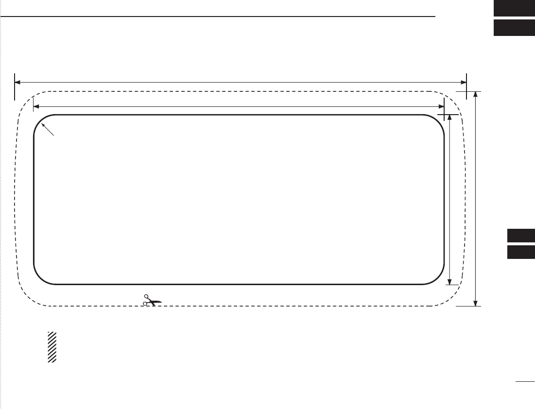
57
12
TEMPLATE
1
2
3
4
5
6
7
8
9
10
11
12
13
14
15
16
Cut here
Unit: mm
164
78
149
61.6
R8 (Max.)
NOTE: The solid line is the line to use when cutting into the dash/helm.
The dotted line shows the outline of the IC-M412’s front panel once the radio is fitted into the hole.
Do not follow the dotted line when making the hole in your dash/helm.
New2001

New2001
MEMO
New2001
1
2
3
4
5
6
7
8
9
10
11
12
13
14
15
16

1-1-32 Kamiminami, Hirano-ku, Osaka 547-0003, Japan
New2001
A-6865?-1US
Printed in Japan
© 2010 Icom Inc.
Printed on recycled paper with soy ink.