ICOM orporated 306000 VHF Transceiver User Manual IC F50V F60V 0
ICOM Incorporated VHF Transceiver IC F50V F60V 0
UserManual.wiki
>
ICOM orporated
>
306000 User Manual
Manual
Navigation menu
Upload a User Manual
Namespaces
Wiki Guide
HTML
PDF
Info
Views
User Manual
Discussion / Help
Navigation
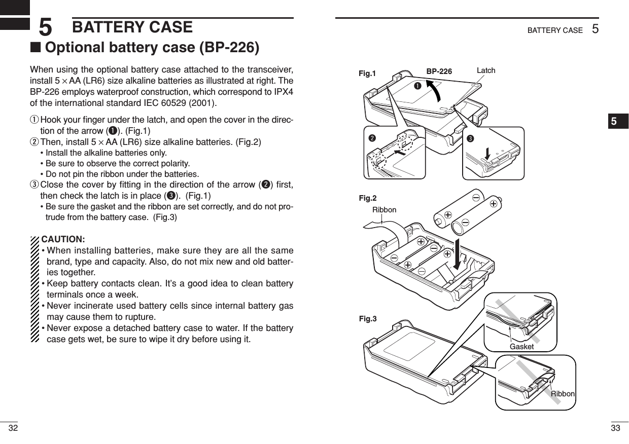
![11ACCESSORIES1234567891011121314151617181920TABLE OF CONTENTSSAFETY TRAINING INFORMATION …………………………………………… iIMPORTANT ……………………………………………………………………… iiiEXPLICIT DEFINITIONS ………………………………………………………… iiiOPERATING NOTES …………………………………………………………… iiiPRECAUTIONS ………………………………………………………………… ivTABLE OF CONTENTS ………………………………………………………… v1 ACCESSORIES ……………………………………………………………… 1–3‘Supplied accessories ……………………………………………………… 1‘Accessory attachments……………………………………………………… 22 PANEL DESCRIPTION …………………………………………………… 4–13‘Front, top and side panels ………………………………………………… 4‘Function display ……………………………………………………………… 6‘Programmable function keys ……………………………………………… 83 BASIC OPERATION……………………………………………………… 14–23‘Turning power ON ………………………………………………………… 14‘Channel selection ………………………………………………………… 14‘Call procedure ……………………………………………………………… 15‘ Receiving and transmitting ……………………………………………… 16‘ User set mode ……………………………………………………………… 20‘ Emergency transmission ………………………………………………… 21‘ Scrambler function ………………………………………………………… 21‘ Stun function ……………………………………………………………… 21‘ Recording function ………………………………………………………… 224 BATTERY CHARGING ………………………………………………… 24–31‘Caution ……………………………………………………………………… 24‘Optional battery chargers ………………………………………………… 275 BATTERY CASE ………………………………………………………… 32–33‘Optional battery case (BP-226)…………………………………………… 326 SPEAKER-MICROPHONE ……………………………………………… 34–35‘Optional HM-168 description ……………………………………………… 34‘Attachment ………………………………………………………………… 357 SWIVEL BELTCLIP ……………………………………………………… 36–37‘MB-86 contents …………………………………………………………… 36‘Attaching …………………………………………………………………… 36‘Detaching …………………………………………………………………… 378 OPTIONS ………………………………………………………………… 38–41v■Supplied accessories*There are no names on the programmable function keys since thefunctions can be freely assigned to [P0] to [P3], [Red], [ ] and[ ] keys.Attach the supplied function name stickers above the appropriatekeys for easy recognition of that key’s assigned function.Battery packAntennaBelt clipKey sticker*Jack cover](https://usermanual.wiki/ICOM-orporated/306000/User-Guide-840528-Page-4.png)
![31ACCESSORIES123456789101112131415161718192021ACCESSORIES■Accessory attachmentsDFlexible antennaConnect the supplied flexible antennato the antenna connector.CAUTION!• NEVER HOLD the antenna whencarrying the transceiver.•Transmitting without an antennamay damage the transceiver.ïBattery packTo attach the battery pack:Slide the battery pack on the back of the transceiver in the direc-tion of the arrow (q), then lock it with the battery release button.• Slide the battery pack until the battery release button makes a ‘click’sound.To release the battery pack:Push the battery release button in the direction of the arrow (w) asshown below. The battery pack is then released.qwBattery packBattery release buttonNEVER release or at-tach the battery packwhen the transceiveris wet or soiled. Thismay result water ordust getting into thetransceiver/batterypack and may resultin the transceiverbeing damaged.ïJack coverAttach the jack cover when the optional equipment is not used.DBelt clipAttach the belt clip to the back of the transceiver with the suppliedscrews.Supplied screwswJack cover[SP MIC] jackScrewqerTo attach the jack cover:qInsert the jack cover into the[SP MIC] jack.wTighten the screw.To detach the jack cover:eUnscrew the screw using aphillips screwdriver.rDetach the jack cover for theoptional equipment connec-tion.](https://usermanual.wiki/ICOM-orporated/306000/User-Guide-840528-Page-5.png)
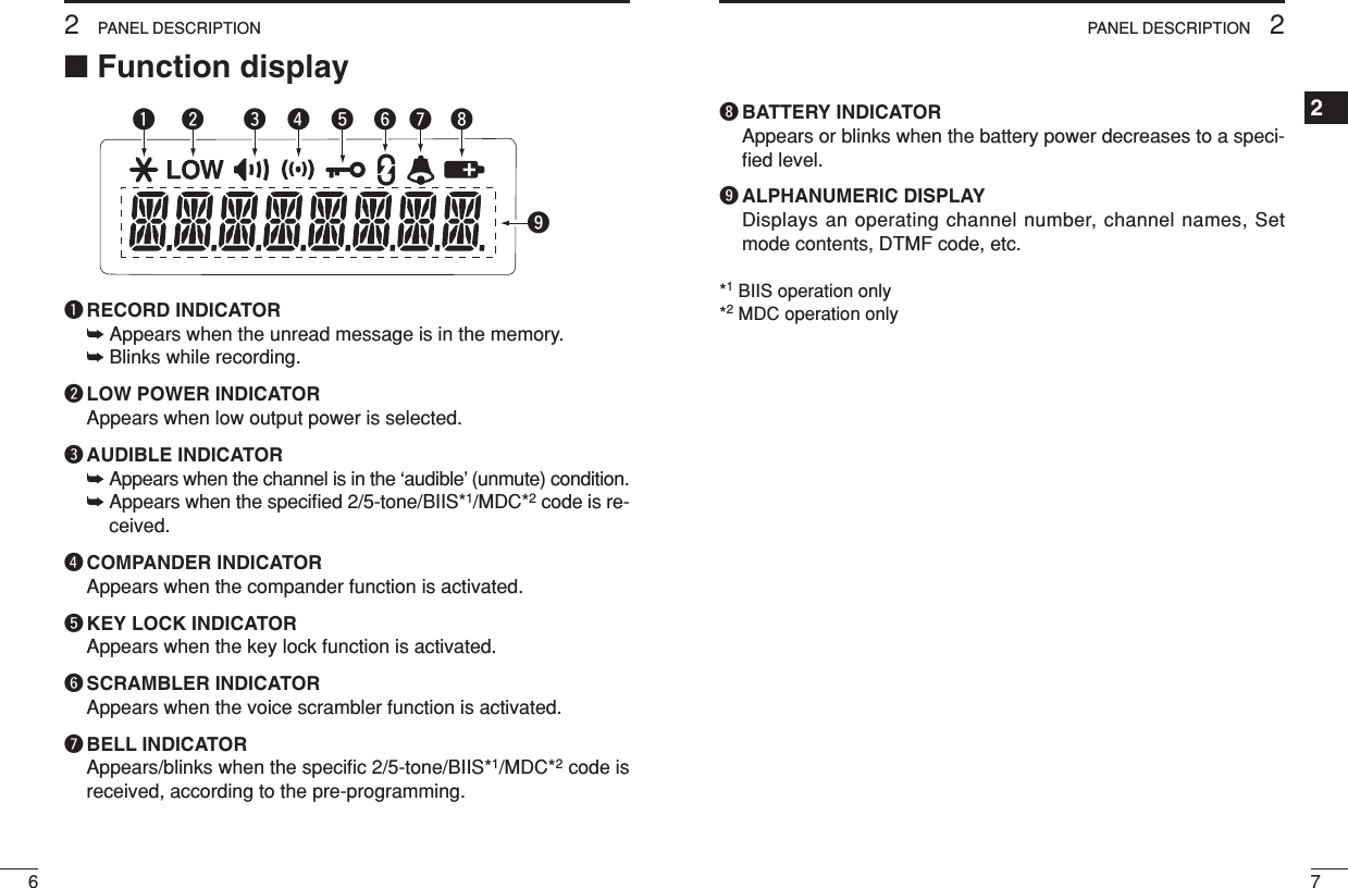
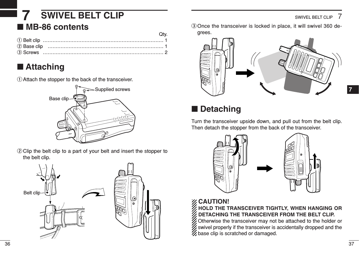
![52PANEL DESCRIPTION242PANEL DESCRIPTION■Front, top and side panelsqVOLUME CONTROL [VOL]Turns power ON and adjusts the audio level.wRED BUTTONThe desired function can be assigned by your dealer. (p. 8)eANTENNA CONNECTORConnects the supplied antenna. (p. 2)MicrophoneFunction display(p. 6)wertyuqiSpeakerrEXTERNAL SPEAKER-MICROPHONE JACK [SP MIC]Connects the optional speaker-microphone, etc.tDEALER-PROGRAMMABLE KEYS [P0] to [P3]The desired functions can be assigned independently by yourdealer. (p. 8)yCH UP AND DOWN KEYS [ ]/[ ]Push to select an operating channel, etc.*Desired functions can be assigned independently by your dealer.(p. 8)uTRANSMIT/BUSY INDICATORLights red while transmitting; lights green while receiving a sig-nal, or when the squelch is open.iPTT SWITCH [PTT]➥Push and hold to transmit; release to receive.➥When the recording function is activated, TX voice messagecan be recorded while pushing and holding [PTT]. (p. 22)[SP MIC] jack coverNOTE: KEEP the [SP MIC] jack cover attached to the transceiver when the optional equipment is not used. (See p. 3 for details)](https://usermanual.wiki/ICOM-orporated/306000/User-Guide-840528-Page-6.png)
![82PANEL DESCRIPTION92PANEL DESCRIPTION2SCAN B START/STOP KEY➥Push to start and cancel scanning operation. Scan resumesafter a specified time period has passed when scan is cancelledexcept for this key.➥Push and hold this key for 1 sec. to indicate the scan group, thenselect the desired group using [CH Up]/[CH Down].SCAN ADD/DEL (TAG) KEY➥Push to add or delete the selected channel to/from the scangroup.1. Push to indicate the scan group, then push [CH Up] or [CH Down]to select the desired group.2. Push to add or delete the channel to/from the selected scan group.3. Push and hold for 1 sec. to exit the scan group selection mode.➥Push this key while scan is paused (a signal is detected) on achannel (except for priority channel,) the channel is cleared fromthe scan group.Depending on the setting, the cleared channel is added to thescan group again after the scan is cancelled. (NuisanceDelete function)PRIORITY CHANNEL KEYS➥Push to select Priority A or Priority B channel.➥Push and hold [Prio A (Rewrite)] or [Prio B (Rewrite)] to set theoperating channel as the Priority A or Priority B channel.MR-CH 1/2/3/4 KEYSPush to select the memory channel 1 to 4 directly.LOCK KEYPush and hold to toggle the key lock function ON and OFF.• All programmable keys except the following are electronically lockedwhen the key lock function is activated: [PTT], [Light], [Surveillance],[Call] (incl. Call A and Call B), [Moni(Audi)] and [Emergency].■Programmable function keysThe following functions can be assigned to [P0], [P1], [P2], [P3],[Red], []and []programmable function keys. Consult your Icom dealer or system operator for details concerningyour transceivers programming.If the programmable function names are bracketed in the followingexplanations, the specific key is used to activate the function de-pends on programming.CH UP AND DOWN KEYS➥Push to select an operating channel.➥Push to select a transmit code channel after pushing [TX CodeCH Select].➥Push to select a DTMF channel after pushing [DTMF Autodial].➥Push to select a scan group after pushing and holding [Scan AStart/Stop]/[Scan B Start/Stop].ZONE SELECT KEYPush this key, then select the desired zone using [CH Up]/[CHDown].What is “zone”?—The desired channels are assigned into azone according to the intended use for grouping. For example,‘Staff A’and ‘Staff B’are assigned into a “Business” zone, and‘John’and ‘Cindy’are assigned into a “Private” zone.SCAN A START/STOP KEY➥This key’s operation depends on the Power ON Scan setting.When the power ON scan function is turned OFF;Push to start and cancel scanning operation.When the power ON scan function is turned ON;Push to pause scanning, then resumes scanning after a speci-fied time period has passed.➥Push and hold this key for 1 sec. to indicate the scan group, thenselect the desired group using [CH Up]/[CH Down].](https://usermanual.wiki/ICOM-orporated/306000/User-Guide-840528-Page-8.png)
![112PANEL DESCRIPTION2102PANEL DESCRIPTIONTALK AROUND KEYPush to turn the talk around function ON and OFF.•The talk around function equalizes the transmit frequency to the re-ceive frequency for transceiver-to-transceiver communication.WIDE/NARROW KEYPush to toggle the IF bandwidth between wide and narrow.• The wide passband width can be selected from 25.0 or 20.0 kHz usingthe CS-F50V CLONING SOFTWARE. (PMR operation only) Ask yourdealer for details.DTMF AUTODIAL KEY➥Push to enter the DTMF channel selection mode. Then selectthe desired DTMF channel using [CH Up]/[CH Down].➥After selecting the DTMF channel, push again to transmit the se-lected DTMF code.DTMF RE-DIAL KEYPush to transmit the last-transmitted DTMF code.• TX memories are cleared after turning the transceiver OFF.CALL KEYSPush to transmit a 2/5-tone/BIIS ID code.•Call transmission is necessary before calling another station depend-ing on your signalling system.•[Call A] and/or [Call B] may be available when your system employsselective ‘Individual/Group’calls. Ask your dealer which call is as-signed to each key.SURVEILLANCE KEYPush to turn the surveillance function ON or OFF.When this function is turned ON, the beep is not emitted and theLCD backlight and the LED indicator do not light when a signal isreceived or a key is pushed.MONITOR KEY➥Mute and release the CTCSS (DTCS) or 2-tone squelch mute.Open any squelch/deactivate any mute while pushing and hold-ing this key. (LMR operation only)➥Activates one of (or two of) the following functions on each chan-nel independently: (PMR operation only)• Push and hold to un-mute the channel (audio is emitted; ‘Audible’condition).• Push to mute the channel (sets to ‘Inaudible’only).• Push after the communication is finished to send a ‘reset code’.(BIIS operation only)NOTE: The un-mute condition (‘Audible’condition) may auto-matically return to the mute condition (‘Inaudible‘ condition)after a specified period.LIGHT KEYPush to turn the backlight ON for about 5 sec. even if the backlightfunction is turned OFF in user set mode.HIGH/LOW KEYPush to select the transmit output power temporarily or perma-nently, depending on the pre-setting.•Ask your dealer for the output power level for each selection.C.TONE CHANNEL ENTER KEYPush to enter the continuous tone channel selection mode, and push[CH Up]/[CH Down] to change the tone frequency/code setting. Theselected channel remains set as the continuous tone channel untilanother channel is designated as such.](https://usermanual.wiki/ICOM-orporated/306000/User-Guide-840528-Page-9.png)
![132PANEL DESCRIPTION1234567891011121314151617181920122PANEL DESCRIPTIONCOMPANDER KEYPush to turn the compander function ON and OFF. The compander function reduces noise components from the trans-mitting audio to provide clear communication.USER SET MODE KEY➥Push and hold to enter user set mode.• During user set mode, push this key to select an item, and push[CH Up]/[CH Down] to change the value or condition.➥Push and hold this key again to exit user set mode.•User set mode is also available via the ‘Power ON function’. Pleaserefer to p. 20 also.PLAYBACK KEY (p. 23)➥Push to playback the recorded messages in sequence from thenewest one.• A short beep is emitted after playing back each message.• A long beep is emitted after playing back all messages.• An error beep is emitted when no message is in the memory.➥While playing back the message, push and hold for 1 sec. todelete the selected message.PLAYBACK/REC KEY (pgs. 22, 23)➥Push to playback the recorded messages in sequence from thenewest one.• A short beep is emitted after playing back each message.• A long beep is emitted after playing back all messages.• “NO REC” is displayed when no message is in the memory.➥Push and hold for 1 sec. to start recording. And then, push againto stop recording.➥While playing back the message, push and hold for 1 sec. todelete the selected message.EMERGENCY KEYSPush and hold to transmit the emergency call.• The emergency call is transmitted with beep emission and no displaychanges.• The transceiver can transmit the emergency call silently or with thedisplay changes depending on the pre-setting. Ask your dealer for de-tails.• If you want to cancel the emergency call, push and hold the key againbefore transmitting the call.• The emergency call is transmitted one time only or repeatedly until re-ceiving a control code depending on the pre-setting.TX CODE ENTER KEY (PMR operation only)Push to enter the TX code edit mode. Then set the desired digitusing [CH Up]/[CH Down]. (p. 19)TX CODE CHANNEL SELECT KEY➥Push to enter the TX code channel selection mode. Then selectthe desired channel using [CH Up]/[CH Down]. (p. 18)➥While in the TX code channel selection mode, push and hold for1 sec. to enter the TX code edit mode. Then set the desired digitusing [CH Up]/[CH Down]. (p. 19; PMR operation only)TX CODE CHANNEL UP/DOWN KEYSPush to select a TX code channel directly.ID-MR SELECT KEY (PMR operation only)➥Recalls detected ID codes.•Push this key, then push [CH Up]/[CH Down] for selection.•Up to 5 ID’s are memorized.➥Push and hold to erase the selected memorized ID’s.VOICE SCRAMBLER FUNCTIONPush to turn the voice scrambler function ON and OFF.](https://usermanual.wiki/ICOM-orporated/306000/User-Guide-840528-Page-10.png)
![153BASIC OPERATION1234567891011121314151617181920143BASIC OPERATION■Turning power ONqRotate [VOL] to turn power ON.• When the opening vibration function is turned ON, the transceivervibrates for 2 sec. Ask your dealer for details.wIf the transceiver is programmed for a start up passcode, inputdigit codes as directed by your dealer.• The keys in the table below can be used for password input:• The transceiver detects numbers in the same block as identical.Therefore “01234” and “56789” are the same.eWhen the “PASSWORD” indication does not clear after inputting4 digits, the input code number may be incorrect. Turn the poweroff and start over in this case.■Channel selectionSeveral types of channel selections are available. Methods may dif-fer according to your system set up.NON-ZONE TYPE:Push [CH Up]/[CH Down] to select the desired operating channelin sequence; or, push one of [MR-CH 1] to [MR-CH 4] to select achannel directly.ZONE TYPE:Push [Zone] then push [CH Up]/[CH Down] to select the desired zone.AUTOMATIC SCAN TYPE:Channel setting is not necessary for this type. When turning thepower ON, the transceiver automatically starts scanning. Scanningstops when receiving a call.KEYNUMBER 0549382716or■Call procedureWhen your system employs tone signalling (excluding CTCSS andDTCS), the call procedure may be necessary prior to voice trans-mission. The tone signalling employed may be a selective callingsystem which allows you to call specific station(s) only and preventunwanted stations from contacting you.qSelect the desired TX code channel or 2/5-tone code accordingto your System Operator’s instructions.• This may not be necessary depending on programming.• Refer to pgs. 18, 19 for selection.wPush [Call] (assigned to one of the dealer programmable keys).eAfter transmitting, the remainder of your communication can becarried out in the normal fashion.Selective calling Non-selective calling](https://usermanual.wiki/ICOM-orporated/306000/User-Guide-840528-Page-11.png)
![173BASIC OPERATION3163BASIC OPERATION■Receiving and transmittingNOTE: Transmitting without an antenna may damage the trans-ceiver. See p. 2 for antenna attachment.Receiving:qRotate [VOL] to turn power ON.wPush [CH Up] or [CH Down] to select a channel.eWhen receiving a call, adjust the audio output level to a comfort-able listening level.Transmitting:Wait for the channel to become clear to avoid interference.qWhile pushing and holding [PTT], speak into the microphone at anormal voice level.• When a tone signalling system is used, the call procedure de-scribed at left may be necessary.wRelease [PTT] to return to receive.IMPORTANT: To maximize the readability of your signal;1. Pause briefly after pushing [PTT].2. Hold the microphone 5 to 10 cm (2 to 4 inches) from yourmouth, then speak into the microphone at a normal voicelevel.DReceiving note• Vibration function (Depends on the version)When the matched RX code signal is received, the transceiver mayvibrate for a specified time period depends on the pre-setting. Pushany key or [PTT] to stop the vibration.NOTE:• The transceiver cannot stop the vibration suddenly after push-ing any key or [PTT].• The vibration sound may be heared at the communicationparty, or be recorded if the recording function is activated when[PTT] is pushed to stop the vibration.DTransmitting notes• Transmit inhibit functionThe transceiver has several inhibit functions which restrict trans-mission under the following conditions:- The channel is in mute condition (‘Inaudible’condition; “”does not appear).- The channel is busy.- Un-matched (or matched) CTCSS is received. (Depending onthe pre-setting)- The selected channel is a ‘receive only’channel.• Time-out timerAfter continuous transmission for the pre-programmed time period,the time-out timer is activated, causing the transceiver to stop trans-mitting.• Penalty timerOnce the time-out timer is activated, transmission is further inhibitedfor a period determined by the penalty timer.](https://usermanual.wiki/ICOM-orporated/306000/User-Guide-840528-Page-12.png)
![193BASIC OPERATION3183BASIC OPERATIONDTX code channel selectionIf the transceiver has [TX Code CH Select] assigned to it, the indi-cation can be toggled between the operating channel number (orname) and TX code channel number (or name). When the TX codechannel number (or name) is displayed, [CH Up] or [CH Down] se-lects the TX code channel.USING [TX CODE CH SELECT] KEY:qPush [TX Code CH Select]— a TX code channel number (orname) appears.wPush [CH Up] or [CH Down] to select the desired TX code chan-nel.ePush [Call] to transmit the selected TX code.USING [TX CODE CH UP]/[TX CODE CH DOWN] KEY:If the transceiver has a [TX Code CH Up] or [TX Code CH Down]key assignment, the programmed TX code channel can be selecteddirectly when pushed.DTX code number edit (PMR operation only)If the transceiver has [TX Code CH Select] or [TX Code Enter] as-signed to it, TX code contents can be edited within the allowable digits.USING [TX CODE CH SELECT] KEY:qPush [TX Code CH Select] to enter the TX code channel selec-tion mode.• Select the desired operating channel before entering the TX codechannel selection mode if necessary.wPush [TX Code CH Select] for 1 sec. to enter the TX code edit mode.• The digit to be edited blinks.ePush [TX Code CH Select] to select the desired digit to be edited.rPush [CH Up]/[CH Down] to select the desired digit.tPush [TX Code CH Select] to set. The digit to the right will blinkautomatically.yRepeat rand tto edit all allowable digits.uAfter editing, push [TX Code CH Select] to set.• Return to the stand by mode.iPush [Call] to transmit.USING [TX CODE ENTER] KEY:qAfter pushing [TX Code CH Select], push [CH Up] or [CH Down],or push [TX Code CH Up] or [TX Code CH Down] to select thedesired TX code channel.wPush [TX Code Enter] to enter the TX code edit mode.• The digit to be edited blinks.ePush [TX Code Enter] to select the desired digit to be edited.rPush [CH Up]/[CH Down] to select the desired digit.tPush [TX Code Enter] to set. The digit to the right will blink auto-matically.yRepeat rand tto edit all allowable digits.uAfter editing, push [TX Code Enter] to set.• Return to the stand by mode.iPush [Call] to transmit.](https://usermanual.wiki/ICOM-orporated/306000/User-Guide-840528-Page-13.png)
![213BASIC OPERATION3203BASIC OPERATIONDDTMF transmissionIf the transceiver has [DTMF Autodial] assigned to it, the automaticDTMF transmission function is available. Up to 8 DTMF channelsare available.qPush [DTMF Autodial]— a DTMF channel appears.wPush [CH Up] or [CH Down] to select the desired DTMF channel.ePush [DTMF Autodial] to transmit the DTMF code to the selectedDTMF channel.■User set modeUser set mode is accessed at power ON and allows you to set sel-dom-changed settings. In this case you can “customize” the trans-ceiver operation to suit your preferences and operating style.Entering the user set mode:qWhile pushing and holding [ ] and [ ], rotate [VOL] to powerON.• Turn power OFF in advance.• “SET MODE” appears for 1 sec.wPush and hold [P0] for 1 sec. to enter user set mode.ePush [P0] momentarily to select the appropriate item.Then push [ ] or [ ] to set the desired level/condition.• Available set mode functions are Backlight, Beep, SQL Level,Ringer Level, AF Min level, Mic Gain, VOX Gain*, VOX Delay*,Battery Voltage, Signal Moni, Vibration and Lone Worker.rPush and hold [P0] again to exit set mode.* Appears when the optional headset is connected.User set mode is also available using a programmable key. Pleaserefer to p. 13 [User Set Mode] section.NOTE: [ ], [ ] and [P0] activate while in the user set moderegardless of the assigned key functions.■Emergency transmissionWhen [Emergency] is pushed, an emergency signal is automaticallytransmitted for the specified time period.When [Emergency] is pushed for the specified time period, theDTMF emergency signal is transmitted once or repeatedly on theemergency channel. However, when no emergency channel isspecified, the signal is transmitted on the previously selected chan-nel.If you want to cancel the emergency call, push and hold the keyagain before transmitting the call.■Scrambler functionThe scrambler function provides a private communication betweenstations with the same scrambler codes.qPush [Scrambler] to turn the scrambler function ON.• “” appears.wPush [Scrambler] again to turn the scrambler function OFF.■Stun functionWhen the specified ID, set as a killer ID, is received, the stun func-tion is activated.When the killer ID is received, the transceiver switches to the pass-word required condition. Entering of the password via the keypad isnecessary to operate the transceiver again in this case.](https://usermanual.wiki/ICOM-orporated/306000/User-Guide-840528-Page-14.png)
![233BASIC OPERATION1234567891011121314151617181920223BASIC OPERATION■Recording function (Depends on the version)The transceiver has a recording function that records the TX/RXvoice messages. When the specified ID is received, the automaticrecording function activates and records the voice message for aspecified time period.Or, if the transceiver has [Playback/Rec] assigned to it, manualrecording is also available.Automatic recording:qWhen the specified ID is received, the recording function is au-tomatically activated.• “” blinks.wWhile pushing and holding [PTT], speak into the microphone at anormal voice level.• The TX voice message is recorded.eRelease [PTT] to receive.• The RX voice message is recorded.rThe recording operation automatically stops after the specifiedtime period has passed, exhausting the recording memory, op-erating any key (except [PTT]), or transmitting a single tone.• “” stops blinking.• Pushing [Playback/Rec] (if assigned) also stops recording.Manual recording:qPush and hold [Playback/Rec] for 1 sec. to activate the recordingfunction.• “” blinks.wWhile pushing and holding [PTT], speak into the microphone at anormal voice level.• The TX voice message is recorded.eRelease [PTT] to receive.• The RX voice message is recorded.rPush [Playback/Rec] again to stop recording.• “” stops blinking.• The recording operation stops at exhausting the recording memory,operating any key (except [PTT]), or transmitting a single tone.Playing back:The recorded voice messages are played back with [Playback] or[Playback/Rec].• “” appears on the function display when the unplayed message is inthe recording memory.➥Push [Playback] or [Playback/Rec] to playback the recordedmessage in sequence from the newest one.• Push [CH Up] or [CH Down] to select the desired message.• A short beep is emitted after playing back each message.• A long beep is emitted after playing back all messages.• During playback mode, “” appears when the unplayed messageis played back, or “” disappears when the played message isplayed back.• “” disappears after playing back the unplayed message for thespecified time period.NOTE: You can transmit the recording message with [PTT] whileplaying back the message.Deleting the message:➥While playing back the message, push and hold [Playback] or[Playback/Rec] for 1 sec. to delete the playing back message.➥While pushing and holding [P0] and [CH Up], turn power ON todelete all messages in the recording memory.](https://usermanual.wiki/ICOM-orporated/306000/User-Guide-840528-Page-15.png)
![356SPEAKER-MICROPHONE1234567891011121314151617181920346SPEAKER-MICROPHONE■Optional HM-168 descriptionNEVER immerse the connector in water. If the connector becomeswet, be sure to dry it BEFORE attaching it to the transceiver.NOTE: The microphone is located at the top of the speaker-mi-crophone, as shown in the diagram above. To maximize thereadability of your transmitted signal (voice), hold the micro-phone approx. 5 to 10 cm (2 to 4 inches) from your mouth, andspeak in a normal voice level.Alligator type clipTo attach the speaker-mic.to your shirt or collar, etc.PTT switchTransmits while pushedReceives while releasedMicrophoneSpeakerTurn the transceiver power OFF when connecting the HM-168.■AttachmentAttach the connector of the speaker-microphone into the [SP MIC]jack on the transceiver and tighten the screw.IMPORTANT: KEEP the [SP MIC] jack cover attached to thetransceiver when the speaker-microphone is not in use. (p. 3)Water will not get into the transceiver even if the cover is not at-tached, however, the terminals (pins) will become rusty, or thetransceiver will function abnormally if the connector becomeswet.CAUTION: Attach the [SP MIC] jack securely to prevent accidental drop-ping, or water intrusion in the jack.](https://usermanual.wiki/ICOM-orporated/306000/User-Guide-840528-Page-21.png)
![417OPTIONS1234567891011121314151617181920407OPTIONSïAbout VS-1SC VOX/PTT CASEThe VS-1SC is a VOX/PTT unit for Icom handheld transceivers,and allows you hands-free operation.An optional headset (HS-94, etc.) is required for operation.• The VOX (Voice Operated Transmission) function starts transmissionwithout pushing PTT switch when you speak into the microphone;then, automatically returns to receive when you stop speaking.Features➥9-pin Spring-plug type head SP/MIC plug is equipped➥Water resistant construction➥Durable construction➥Equipped with a PTT switch and revolving clipVS-1SCWater protection coverPTT switchMIC/VOX gainadjusting potVOX/PTT select switchVOX gain and delay adjustmentqAttach the connector of the VS-1SC into the [SP/MIC] con-nector on the transceiver and tighten the screw.• Toggle the toggle switch to [VOX].wEnter user set mode. (pgs. 13, 20)ePush [P0] several times to select the “VOX Gain” or “VOXDelay” items. Then, push [ ] or [ ] to set the desiredlevel/condition.rRotate [VOL] to turn the power OFF to exit set mode.• VOX GainThe VOX sensitivity level can be adjusted from OFF or 1 to 6(more sensitive).• VOX DelayThe VOX delay time can be set from 0.5 to 3.0 sec. (0.5 sec.step) for a convenient interval before returning to receive.NOTE: MIC/VOX gain can be adjusted via the Adjusting potusing a thin screw driver.VOX delay timer is 0.5 sec. (default)VOX gain level is 3 (default)](https://usermanual.wiki/ICOM-orporated/306000/User-Guide-840528-Page-24.png)