ICOM orporated 306200 VHF Transeiver User Manual IC F70 F80
ICOM Incorporated VHF Transeiver IC F70 F80
UserManual.wiki
>
ICOM orporated
>
306200 User Manual
>
User Manual
Contents
1.
User Manual
2.
Revised User Manual
3.
Accessory Specification AD-118
4.
Updated Manual
User Manual
Navigation menu
Upload a User Manual
Namespaces
Wiki Guide
HTML
PDF
Info
Views
User Manual
Discussion / Help
Navigation
![31ACCESSORIES1ïJack coverAttach the jack cover when the optional speaker-microphoneis not used.qwerTo attach the jack cover:qInsert the jack cover intothe [SP MIC] connector.wTighten the screw.To detach the jack cover:eUnscrew the screw with aphillips screwdriver.rDetach the jack cover forthe speaker-microphoneconnection.!IC-F70_F80.qxd 04.11.9 0:01 PM Page 3 (1,1)](https://usermanual.wiki/ICOM-orporated/306200.User-Manual/User-Guide-952714-Page-8.png)
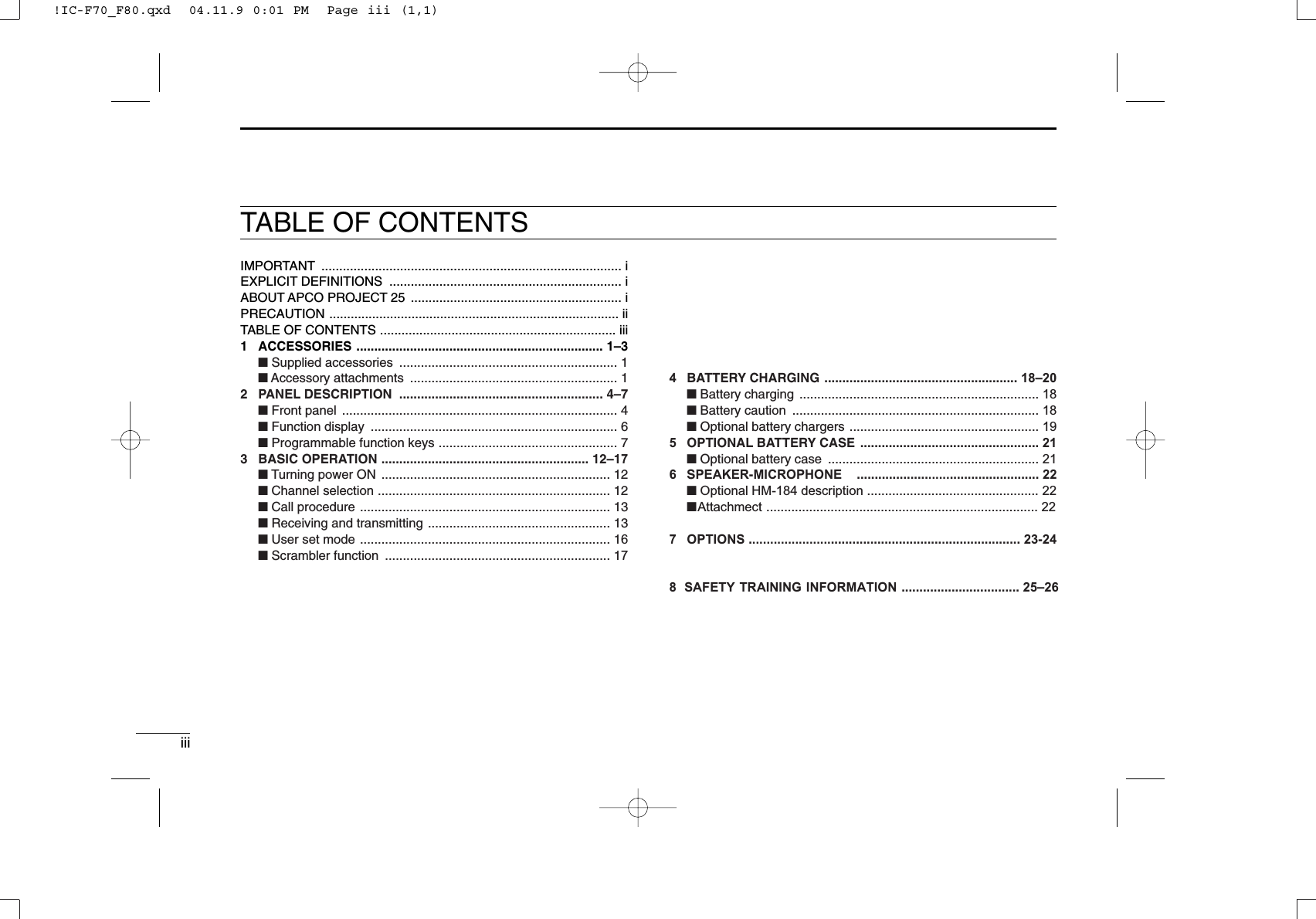
![42PANEL DESCRIPTIONFront panelA .VOLUME CONTROL [VOL]Rotate to turn the power ON/OFF and adjusts the audiolevel.B .ROTARY SELECTORRotate to select the pre-programmed memory channels orthe operating bank.(Depending on the pre-setting)C .ANTENNA CONNECTORConnects the supplied antenna.D .EMERGENCY SWITCHPush and hold for a specied period to transmit an emer-gency call.*Desired function can be programmed by your dealer. (p. 7)E .BUSY/TRANSMIT INDICATORLights green while receiving a signal, or when thesquelch is open.Lights red while transmitting.F .[SP/MIC] JACKConnect the optional speaker-microphone.G .FUNCTION DISPLAY (p. 6)Displays a variety of information, such as an operatingchannel number/name, 5-tone code, DTMF numbers andaudible condition, etc.H .DEALER-PROGRAMMABLE KEYSDesired functions can be programmed independently byyour dealer. (p. 7)42PANEL DESCRIPTIONFront panelA .VOLUME CONTROL [VOL]Rotate to turn the power ON/OFF and adjusts the audiolevel.B .ROTARY SELECTORRotate to select the pre-programmed memory channels orthe operating bank.(Depending on the pre-setting)C .ANTENNA CONNECTORConnects the supplied antenna.D .EMERGENCY SWITCHPush and hold for a specied period to transmit an emer-gency call.*Desired function can be programmed by your dealer. (p. 7)E .BUSY/TRANSMIT INDICATORLights green while receiving a signal, or when thesquelch is open.Lights red while transmitting.F .[SP/MIC] JACKConnect the optional speaker-microphone.G .FUNCTION DISPLAY (p. 6)Displays a variety of information, such as an operatingchannel number/name, 5-tone code, DTMF numbers andaudible condition, etc.H .DEALER-PROGRAMMABLE KEYSDesired functions can be programmed independently byyour dealer. (p. 7)[SP/MIC] jack coverNOTE: Attach the [SP/MIC] jack cover when the optional speaker-microphone is not used. (See p. 3 for details)[SP/MIC] jack coverNOTE: Attach the [SP/MIC] jack cover when the optional speaker-microphone is not used. (See p. 3 for details)[SP/MIC] jack coverNOTE: Attach the [SP/MIC] jack cover when the optional speaker-microphone is not used. (See p. 3 for details)[SP/MIC] jack coverNOTE: Attach the [SP/MIC] jack cover when the optional speaker-microphone is not used. (See p. 3 for details)[SP/MIC] jack coverNOTE: Attach the [SP/MIC] jack cover when the optional speaker-microphone is not used. (See p. 3 for details)[SP/MIC] jack coverNOTE: Attach the [SP/MIC] jack cover when the optional speaker-microphone is not used. (See p. 3 for details)[SP/MIC] jack coverNOTE: Attach the [SP/MIC] jack cover when the optional speaker-microphone is not used. (See p. 3 for details)[SP/MIC] jack coverNOTE: Attach the [SP/MIC] jack cover when the optional speaker-microphone is not used. (See p. 3 for details)AB C D ESpeaker I F G HAB C D ESpeaker I F G HAB C D ESpeaker I F G HAB C D ESpeaker I F G HAB C D ESpeaker I F G HAB C D ESpeaker I F G HAB C D ESpeaker I F G HAB C D ESpeaker I F G H42PANEL DESCRIPTIONFront panelA .VOLUME CONTROL [VOL]Rotate to turn the power ON/OFF and adjusts the audiolevel.B .ROTARY SELECTORRotate to select the pre-programmed memory channels orthe operating bank.(Depending on the pre-setting)C .ANTENNA CONNECTORConnects the supplied antenna.D .EMERGENCY SWITCHPush and hold for a specied period to transmit an emer-gency call.*Desired function can be programmed by your dealer. (p. 7)E .BUSY/TRANSMIT INDICATORLights green while receiving a signal, or when thesquelch is open.Lights red while transmitting.F .[SP/MIC] JACKConnect the optional speaker-microphone.G .FUNCTION DISPLAY (p. 6)Displays a variety of information, such as an operatingchannel number/name, 5-tone code, DTMF numbers andaudible condition, etc.H .DEALER-PROGRAMMABLE KEYSDesired functions can be programmed independently byyour dealer. (p. 7)42PANEL DESCRIPTIONFront panelA .VOLUME CONTROL [VOL]Rotate to turn the power ON/OFF and adjusts the audiolevel.B .ROTARY SELECTORRotate to select the pre-programmed memory channels orthe operating bank.(Depending on the pre-setting)C .ANTENNA CONNECTORConnects the supplied antenna.D .EMERGENCY SWITCHPush and hold for a specied period to transmit an emer-gency call.*Desired function can be programmed by your dealer. (p. 7)E .BUSY/TRANSMIT INDICATORLights green while receiving a signal, or when thesquelch is open.Lights red while transmitting.F .[SP/MIC] JACKConnect the optional speaker-microphone.G .FUNCTION DISPLAY (p. 6)Displays a variety of information, such as an operatingchannel number/name, 5-tone code, DTMF numbers andaudible condition, etc.H .DEALER-PROGRAMMABLE KEYSDesired functions can be programmed independently byyour dealer. (p. 7)[SP/MIC] jack coverNOTE: Attach the [SP/MIC] jack cover when the optional speaker-microphone is not used. (See p. 3 for details)[SP/MIC] jack coverNOTE: Attach the [SP/MIC] jack cover when the optional speaker-microphone is not used. (See p. 3 for details)[SP/MIC] jack coverNOTE: Attach the [SP/MIC] jack cover when the optional speaker-microphone is not used. (See p. 3 for details)[SP/MIC] jack coverNOTE: Attach the [SP/MIC] jack cover when the optional speaker-microphone is not used. (See p. 3 for details)[SP/MIC] jack coverNOTE: Attach the [SP/MIC] jack cover when the optional speaker-microphone is not used. (See p. 3 for details)[SP/MIC] jack coverNOTE: Attach the [SP/MIC] jack cover when the optional speaker-microphone is not used. (See p. 3 for details)[SP/MIC] jack coverNOTE: Attach the [SP/MIC] jack cover when the optional speaker-microphone is not used. (See p. 3 for details)[SP/MIC] jack coverNOTE: Attach the [SP/MIC] jack cover when the optional speaker-microphone is not used. (See p. 3 for details)AB C D ESpeaker I F G HAB C D ESpeaker I F G HAB C D ESpeaker I F G HAB C D ESpeaker I F G HAB C D ESpeaker I F G HAB C D ESpeaker I F G HAB C D ESpeaker I F G HAB C D ESpeaker I F G H!IC-F70_F80.qxd 04.11.9 0:01 PM Page 4 (1,1)!IC-F70_F80.qxd 04.11.9 0:01 PM Page 4 (1,1)!IC-F70_F80.qxd 04.11.9 0:01 PM Page 4 (1,1)!IC-F70_F80.qxd 04.11.9 0:01 PM Page 4 (1,1)JKLM](https://usermanual.wiki/ICOM-orporated/306200.User-Manual/User-Guide-952714-Page-9.png)
![52PANEL DESCRIPTION2I . 10-KEYPAD (IC-F9011T only )The keypad allows you to enter digits to:• Select memory channels, tone channels and DTMF codes(when in the DTMF code channel selection mode)• Set TX codes • Input text message for SDM operation• Start up with a password• Input the Individual ID code for digital operation.J . MONITOR SWITCHMute and release the CTCSS (DTCS) or 2-tone squelchmute. Open any squelch/deactivate any mute whilepushing this key. (LMR operation only)Activates one of (or two of) the following functions oneach channel independently. NOTE: The unmute condition (‘audible’conditions)may automatically return to the mute condition(‘inaudible’ condition) after a speciÞed period.*Desired function can be programmed by your dealer. (p. 7)K. PTT SWITCH [PTT]Push and hold to transmit; release to receive.Push to transmit the call during MSK operation, depend-ing on the setting.L . UP/DOWN SWITCHESPush to select an operating channel.Push to select a TX code channel after pushing [TX CODE CH SELECT].Push to select a DTMF channel after pushing [DTMF].Push to select a scan group after pushing and holding[SCAN].Push to select a BIIS code, status number or SDM afterpushing [DIGITAL].*Desired functions can be programmed independently by yourdealer. (p. 7)52PANEL DESCRIPTION2I . 10-KEYPAD (IC-F9011T only )The keypad allows you to enter digits to:• Select memory channels, tone channels and DTMF codes(when in the DTMF code channel selection mode)• Set TX codes • Input text message for SDM operation• Start up with a password• Input the Individual ID code for digital operation.J . MONITOR SWITCHMute and release the CTCSS (DTCS) or 2-tone squelchmute. Open any squelch/deactivate any mute whilepushing this key. (LMR operation only)Activates one of (or two of) the following functions oneach channel independently. NOTE: The unmute condition (‘audible’conditions)may automatically return to the mute condition(‘inaudible’ condition) after a speciÞed period.*Desired function can be programmed by your dealer. (p. 7)K. PTT SWITCH [PTT]Push and hold to transmit; release to receive.Push to transmit the call during MSK operation, depend-ing on the setting.L . UP/DOWN SWITCHESPush to select an operating channel.Push to select a TX code channel after pushing [TX CODE CH SELECT].Push to select a DTMF channel after pushing [DTMF].Push to select a scan group after pushing and holding[SCAN].Push to select a BIIS code, status number or SDM afterpushing [DIGITAL].*Desired functions can be programmed independently by yourdealer. (p. 7)52PANEL DESCRIPTION2I . 10-KEYPAD (IC-F9011T only )The keypad allows you to enter digits to:• Select memory channels, tone channels and DTMF codes(when in the DTMF code channel selection mode)• Set TX codes • Input text message for SDM operation• Start up with a password• Input the Individual ID code for digital operation.J . MONITOR SWITCHMute and release the CTCSS (DTCS) or 2-tone squelchmute. Open any squelch/deactivate any mute whilepushing this key. (LMR operation only)Activates one of (or two of) the following functions oneach channel independently. NOTE: The unmute condition (‘audible’conditions)may automatically return to the mute condition(‘inaudible’ condition) after a speciÞed period.*Desired function can be programmed by your dealer. (p. 7)K. PTT SWITCH [PTT]Push and hold to transmit; release to receive.Push to transmit the call during MSK operation, depend-ing on the setting.L . UP/DOWN SWITCHESPush to select an operating channel.Push to select a TX code channel after pushing [TX CODE CH SELECT].Push to select a DTMF channel after pushing [DTMF].Push to select a scan group after pushing and holding[SCAN].Push to select a BIIS code, status number or SDM afterpushing [DIGITAL].*Desired functions can be programmed independently by yourdealer. (p. 7)52PANEL DESCRIPTION2I . 10-KEYPAD (IC-F9011T only )The keypad allows you to enter digits to:• Select memory channels, tone channels and DTMF codes(when in the DTMF code channel selection mode)• Set TX codes • Input text message for SDM operation• Start up with a password• Input the Individual ID code for digital operation.J . MONITOR SWITCHMute and release the CTCSS (DTCS) or 2-tone squelchmute. Open any squelch/deactivate any mute whilepushing this key. (LMR operation only)Activates one of (or two of) the following functions oneach channel independently. NOTE: The unmute condition (‘audible’conditions)may automatically return to the mute condition(‘inaudible’ condition) after a speciÞed period.*Desired function can be programmed by your dealer. (p. 7)K. PTT SWITCH [PTT]Push and hold to transmit; release to receive.Push to transmit the call during MSK operation, depend-ing on the setting.L . UP/DOWN SWITCHESPush to select an operating channel.Push to select a TX code channel after pushing [TX CODE CH SELECT].Push to select a DTMF channel after pushing [DTMF].Push to select a scan group after pushing and holding[SCAN].Push to select a BIIS code, status number or SDM afterpushing [DIGITAL].*Desired functions can be programmed independently by yourdealer. (p. 7)!IC-F70_F80.qxd 04.11.9 0:01 PM Page 5 (1,1)!IC-F70_F80.qxd 04.11.9 0:01 PM Page 5 (1,1)!IC-F70_F80.qxd 04.11.9 0:01 PM Page 5 (1,1)!IC-F70_F80.qxd 04.11.9 0:01 PM Page 5 (1,1)M. DEALER-PROGRAMMABLE SWITCH [2-Position SWITCH] [Concentric SWITCH]Desired functions can be programmed independently by yourdealer. (p. 7)](https://usermanual.wiki/ICOM-orporated/306200.User-Manual/User-Guide-952714-Page-10.png)
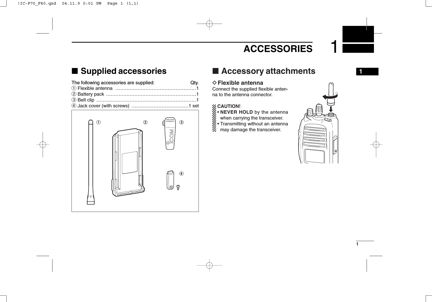
![62PANEL DESCRIPTION■Function displayqSIGNAL STRENGTH INDICATORIndicates relative signal strength level.wLOW POWER INDICATORAppears when low output power is selected.eAUDIBLE INDICATOR➥Appears when the channel is in the ‘audible’(unmute)condition.➥Appears when the specified 2/5-tone/BIIS code isreceived.rCOMPANDER INDICATORAppears when the compander function is activated.tSCRAMBLER INDICATORAppears when the voice scrambler function is activated.yBELL INDICATORAppears/blinks when the specific 2/5-tone/BIIS code isreceived, according to the pre-programming.uCALL CODE MEMORY INDICATORAppears when the call code memory is selected.iSCROLL INDICATORAppears when a received SDM including more than 12characters is displayed.oBATTERY INDICATORAppears or blinks when the battery power decreases to aspecified level.!0 ALPHANUMERIC DISPLAYDisplays an operating channel number, channel name, Setmode contents, DTMF code, etc. The indication mode can be selected from 1 line or 2 lines.Ask your dealer for details.In this instruction manual, the LCD illustration is describedusing the 2 lines indication mode.!1 KEY INDICATORIndicate the programmed function of the front panel keys([P1], [P2], [P3]).XTXC SETq t oiuyrew!0!1!IC-F70_F80.qxd 04.11.9 0:02 PM Page 6 (1,1)](https://usermanual.wiki/ICOM-orporated/306200.User-Manual/User-Guide-952714-Page-11.png)
![72PANEL DESCRIPTION■Programmable function keysThe following functions can be assigned to [DIAL]*, [UP],[DOWN], [P1], [P2], [P3][<],[>]programmable functionkeys.Consult your Icom dealer or system operator for details con-cerning your transceivers programming.If the programmable function names are bracketed in the fol-lowing explanations, the specific key is used to activate thefunction depends on the programming.CH UPAND DOWN KEYS ➥Push to select an operating channel.➥Push to select a transmit code channel after pushing [TXCode CH Select].➥Push to select a DTMF channel after pushing [DTMFAutodial].➥Push to select a scan group after pushing and holding[Scan A Start/Stop]/[Scan B Start/Stop].➥Push to select an Individual ID code or Talkgroup ID codeafter pushing [Individual] or [Talkgroup].ZONE SELECT KEYPush this key, then select the desired zone using [CH Up]/[CH Down].What is “zone”?— The desired channels are assignedinto a zone according to the intended use. For example,‘Staff A’and ‘Staff B’are assigned into a “Business” zone,and ‘John’and ‘Cindy’are assigned into a “Private” zone.SCAN AKEY➥This key’s operation depends on the Power ON Scan setting.When the power ON scan function is turned OFF;Push to start and cancel scanning operation. In case oftransmission during scan, cancels scanning.When the power ON scan function is turned ON;Push to pause scanning. Scanning resumes after a speci-fied time period has passed. In case of transmission duringscan, pauses scanning. Scanning resumes after a specifiedtime period has passed after the transmission is finished.➥Push and hold this key for 1 sec. to indicate the scan group,then select the desired group using [CH Up]/[CH Down].SCAN B KEY➥Push to start and cancel scanning operation. In case oftransmission during scan, pauses scanning. Scanningresumes after a specified time period has passed after thetransmission is finished.➥Push and hold this key for 1 sec. to indicate the scangroup, then select the desired group using [CH Up]/[CH Down].2!IC-F70_F80.qxd 04.11.9 0:02 PM Page 7 (1,1)](https://usermanual.wiki/ICOM-orporated/306200.User-Manual/User-Guide-952714-Page-12.png)
![82PANEL DESCRIPTIONSCAN TAG KEYPush to add or delete the selected channel to/from the scangroup.PRIORITYCHANNELKEYS ➥Push to select Priority A or Priority B channel.➥Push and hold [Prio A (Rewrite)] to rewrite the Prio A chan-nel.MR-CH 1/2/3/4 KEYS Push to select an operating channel directly.MONITOR KEY➥Mute and release the CTCSS (DTCS) or 2-tone squelchmute. Open any squelch/deactivate any mute while push-ing this key.(LMR operation only)LIGHT KEYPush to turn the transceiver’s backlight ON temporarily whenthe backlight function is turned OFF in user set mode.LOCK KEYPush and hold to electronically lock all programmable keysexcept the following:[Call] (incl. Call A and Call B), [Moni(Audi)] and [Emergency].OUTPUT POWER SELECTION KEYPush to select the transmit output power temporarily or per-manently, depending on the pre-setting.•Ask your dealer for the output power level for each selection.C.TONE CHANNELENTER KEYPush to select the continuous tone channel using [CH Up]/[CH Down] to change the tone frequency/code setting. Theselected channel remains set as the continuous tone chan-nel until another channel is designated as such.TALK AROUND KEYTurn the talk around function ON and OFF.•The talk around function equalizes the transmit frequency to thereceive frequency for transceiver-to-transceiver communication.WIDE/NARROW KEYPush to toggle the IF bandwidth between wide and narrow.!IC-F70_F80.qxd 04.11.9 0:02 PM Page 8 (1,1)](https://usermanual.wiki/ICOM-orporated/306200.User-Manual/User-Guide-952714-Page-13.png)
![92PANEL DESCRIPTIONDTMF AUTODIALKEY➥Push to enter the DTMF channel selection mode. Thenselect the desired DTMF channel using [CH Up]/[CH Down].➥After selecting the desired DTMF channel, push this key totransmit the DTMF code.DTMF RE-DIALKEYPush to transmit the last-transmitted DTMF code.CALLKEYS Push to transmit a 2-tone ID code.•Call transmission is necessary before calling another stationdepending on your signalling system.•[Call A] and/or [Call B] may be available when your system employsselective ‘Individual/Group’calls. Ask your dealer which call isassigned to each key.EMERGENCYKEYS ➥Push and hold for a specified period to transmit an emer-gency call.➥When [Emergency Single (Silent)] or [Emergency Repeat(Silent)] is pushed, an emergency call is transmitted withouta beep emission and LCD indication change.• If you want to cancel the emergency call, push (or push andhold) the key again before transmitting the call.• The emergency call is transmitted one time only or repeatedlyuntil receiving a control code depending on the pre-setting.SURVEILLANCE KEYPush to turn the surveillance function ON or OFF.When this function is turned ON, the beep is not emitted andthe LCD backlight does not light when a signal is received ora key is pushed, etc.TX CODE CHANNELSELECT KEY➥Push to enter the ID code channel selection mode directly.Then set the desired channel using [CH Up]/[CH Down]. (p. 14)TX CODE CHANNELUP/DOWN KEYS Push to select a TX code channel directly.2!IC-F70_F80.qxd 04.11.9 0:02 PM Page 9 (1,1)](https://usermanual.wiki/ICOM-orporated/306200.User-Manual/User-Guide-952714-Page-14.png)
![102PANEL DESCRIPTIONVOICE SCRAMBLER FUNCTION Push to toggle the voice scrambler function ON and OFF.COMPANDER KEYPush to toggle the compander function ON and OFF. The compander function reduces noise components from thetransmitted audio to provide clear communication.USER SET MODE KEY➥Push and hold to enter user set mode.• During user set mode, push this key to select an item, andchange the value or condition using push [CH Up]/[CH Down].➥Push and hold this key again to exit user set mode.User set mode is also available via the ‘Power ON function.’Refer to p. 16 also.OPT OUT KEYS Push to control the output signal level from the optional unitconnector.TONE/NAC CH SELECT KEY➥While in the analog mode operation, push to select thecontinuous tone channel using [CH Up] or [CH Down] tochange the tone frequency/code setting.➥While in the digital mode operation, push to select the NACchannel using [CH Up] or [CH Down] to change the NACcode setting.➥While in the mixed (digital and analog) mode operation,push to select the continuous tone channel using [CH Up]or [CH Down] to change the tone frequency/code setting.Then push this key to enter the setting. After that, the NACchannel selection screen appears. Select the NAC chan-nel using [CH Up] or [CH Down] to change the NAC codesetting. Then push this key to enter the setting.!IC-F70_F80.qxd 04.11.9 0:02 PM Page 10 (1,1)](https://usermanual.wiki/ICOM-orporated/306200.User-Manual/User-Guide-952714-Page-15.png)
![112PANEL DESCRIPTION2DFor Digital mode operation onlyINDIVIDUALKEY➥Push to enter the individual ID code selection mode directly.Then select the desired individual ID code using [CH Up]/[CH Down]. (p. 15)➥Push to stop the beep emission when receiving a matchedindividual ID code.TALKGROUPKEY➥Push to enter the talkgroup ID code selection mode directly.Then select the desired talkgroup ID code using [CH Up]/[CH Down]. (p. 15)➥Push to stop the beep emission when receiving a matchedtalkgroup ID code.!IC-F70_F80.qxd 04.11.9 0:02 PM Page 11 (1,1)](https://usermanual.wiki/ICOM-orporated/306200.User-Manual/User-Guide-952714-Page-16.png)
![123BASIC OPERATIONTurning power ON Rotate [VOL] to turn the power ON.If the transceiver is programmed for a start up password,input the digit codes as directed by your dealer.• 10-keypad* can be used for password input.*IC-F9011T only:• The keys as below can be used for password input:The transceiver detects numbers in the same block as identical.Therefore “01234” and “56789” are the same.When the “PASSWORD” indication does not clear afterinputting 6 digits, the input code number may be incorrect.Turn the power off and start over in this case.Channel selectionSeveral types of channel selections are available. Methodsmay differ according to your system set up.NON-ZONE TYPE:Push [CH Up] or [CH Down], or rotate [ROTARY SELECTOR]*to select the desired operating channel, in sequence; or, pushone of [MR-CH 1] to [MR-CH 4] keys to select a channeldirectly.• Up to 16 pre-programmed channels can be selected via [ROTARYSELECTOR].ZONE TYPE:Push [Zone] then push [CH Up] or [CH Down] or rotate[ROTARY SELECTOR]* to select the desired zone.AUTOMATIC SCAN TYPE:Channel setting is not necessary for this type. When turningpower ON, the transceiver automatically starts scanning.Scanning stops when receiving a call.*Depending on the pre-setting.123BASIC OPERATIONTurning power ON Rotate [VOL] to turn the power ON.If the transceiver is programmed for a start up password,input the digit codes as directed by your dealer.• 10-keypad* can be used for password input.*IC-F9011T only:• The keys as below can be used for password input:The transceiver detects numbers in the same block as identical.Therefore “01234” and “56789” are the same.When the “PASSWORD” indication does not clear afterinputting 6 digits, the input code number may be incorrect.Turn the power off and start over in this case.Channel selectionSeveral types of channel selections are available. Methodsmay differ according to your system set up.NON-ZONE TYPE:Push [CH Up] or [CH Down], or rotate [ROTARY SELECTOR]*to select the desired operating channel, in sequence; or, pushone of [MR-CH 1] to [MR-CH 4] keys to select a channeldirectly.• Up to 16 pre-programmed channels can be selected via [ROTARYSELECTOR].ZONE TYPE:Push [Zone] then push [CH Up] or [CH Down] or rotate[ROTARY SELECTOR]* to select the desired zone.AUTOMATIC SCAN TYPE:Channel setting is not necessary for this type. When turningpower ON, the transceiver automatically starts scanning.Scanning stops when receiving a call.*Depending on the pre-setting.KEYNUMBER 0549382716[P2]/[P3]KEYNUMBER 0549382716[P2]/[P3]KEYNUMBER 0549382716[P2]/[P3]KEYNUMBER 0549382716[P2]/[P3]KEYNUMBER 0549382716[P2]/[P3]KEYNUMBER 0549382716[P2]/[P3]KEYNUMBER 0549382716[P2]/[P3]KEYNUMBER 0549382716[P2]/[P3]123BASIC OPERATIONTurning power ON Rotate [VOL] to turn the power ON.If the transceiver is programmed for a start up password,input the digit codes as directed by your dealer.• 10-keypad* can be used for password input.*IC-F9011T only:• The keys as below can be used for password input:The transceiver detects numbers in the same block as identical.Therefore “01234” and “56789” are the same.When the “PASSWORD” indication does not clear afterinputting 6 digits, the input code number may be incorrect.Turn the power off and start over in this case.Channel selectionSeveral types of channel selections are available. Methodsmay differ according to your system set up.NON-ZONE TYPE:Push [CH Up] or [CH Down], or rotate [ROTARY SELECTOR]*to select the desired operating channel, in sequence; or, pushone of [MR-CH 1] to [MR-CH 4] keys to select a channeldirectly.• Up to 16 pre-programmed channels can be selected via [ROTARYSELECTOR].ZONE TYPE:Push [Zone] then push [CH Up] or [CH Down] or rotate[ROTARY SELECTOR]* to select the desired zone.AUTOMATIC SCAN TYPE:Channel setting is not necessary for this type. When turningpower ON, the transceiver automatically starts scanning.Scanning stops when receiving a call.*Depending on the pre-setting.123BASIC OPERATIONTurning power ON Rotate [VOL] to turn the power ON.If the transceiver is programmed for a start up password,input the digit codes as directed by your dealer.• 10-keypad* can be used for password input.*IC-F9011T only:• The keys as below can be used for password input:The transceiver detects numbers in the same block as identical.Therefore “01234” and “56789” are the same.When the “PASSWORD” indication does not clear afterinputting 6 digits, the input code number may be incorrect.Turn the power off and start over in this case.Channel selectionSeveral types of channel selections are available. Methodsmay differ according to your system set up.NON-ZONE TYPE:Push [CH Up] or [CH Down], or rotate [ROTARY SELECTOR]*to select the desired operating channel, in sequence; or, pushone of [MR-CH 1] to [MR-CH 4] keys to select a channeldirectly.• Up to 16 pre-programmed channels can be selected via [ROTARYSELECTOR].ZONE TYPE:Push [Zone] then push [CH Up] or [CH Down] or rotate[ROTARY SELECTOR]* to select the desired zone.AUTOMATIC SCAN TYPE:Channel setting is not necessary for this type. When turningpower ON, the transceiver automatically starts scanning.Scanning stops when receiving a call.*Depending on the pre-setting.KEYNUMBER 0549382716[P2]/[P3]KEYNUMBER 0549382716[P2]/[P3]KEYNUMBER 0549382716[P2]/[P3]KEYNUMBER 0549382716[P2]/[P3]KEYNUMBER 0549382716[P2]/[P3]KEYNUMBER 0549382716[P2]/[P3]KEYNUMBER 0549382716[P2]/[P3]KEYNUMBER 0549382716[P2]/[P3]!IC-F70_F80.qxd 04.11.9 0:02 PM Page 12 (1,1)!IC-F70_F80.qxd 04.11.9 0:02 PM Page 12 (1,1)!IC-F70_F80.qxd 04.11.9 0:02 PM Page 12 (1,1)!IC-F70_F80.qxd 04.11.9 0:02 PM Page 12 (1,1)[<]/[>]/[P1]/](https://usermanual.wiki/ICOM-orporated/306200.User-Manual/User-Guide-952714-Page-17.png)
![133BASIC OPERATION3■Call procedureWhen your system employs tone signaling (excluding CTCSSand DTCS), the call procedure may be necessary prior to voicetransmission. The tone signalling employed may be a selec-tive calling system which allows you to call specific station(s)only and prevent unwanted stations from contacting you.qSelect the desired TX code channel, 2-tone code,Individual ID code* or Talkgroup ID code* according toyour System Operator’s instructions.• This may not be necessary depending on programming.• Refer to pgs. 11–13 for selection.*Digital mode operation only.wPush the call key (assigned to one of the dealer program-mable keys; except for the Digital mode operation) or [PTT].eAfter transmitting, the remainder of your communicationcan be carried out in the normal fashion.■Receiving and transmittingReceiving:qRotate [VOL] to turn the power ON.wPush [CH Up] or [CH Down], or rotate [ROTARY SELEC-TOR]* to select a channel in sequence.*Depending on the pre-setting.eWhen receiving a call, adjust the audio output level to acomfortable listening level.Transmitting:Wait for the channel to become clear to avoid interference.qPush [CALL] when initiating a call from your side.• Coded audio may be heard from the transceiver, then “”appears.• This operation may not be necessary depending on your signal-ing system. Ask your dealer for details.wWhile pushing and holding [PTT], speak into the micro-phone at your normal voice level.eRelease [PTT] to return to receive.IMPORTANT: To maximize the readability of your signal;1. Pause briefly after pushing [PTT].2. Hold the microphone 5 to 10 cm (2 to 4 inches) fromyour mouth, then speak into the microphone at a normalvoice level.Selective calling Non-selective calling!IC-F70_F80.qxd 04.11.9 0:02 PM Page 13 (1,1)](https://usermanual.wiki/ICOM-orporated/306200.User-Manual/User-Guide-952714-Page-18.png)
![143BASIC OPERATIONDTransmitting notes• Transmit inhibit functionThe transceiver has several inhibit functions which restricttransmission under the following conditions:- The channel is in mute condition (‘Inaudible’condition; “”does not appear.)- The channel is busy.- Un-matched (or matched) CTCSS is received.(Depending on the pre-setting.)- Un-matched (or matched) NAC is received.*(Depending on the pre-setting.)- Un-matched (or matched) Individual ID or Talkgroup ID isreceived.*- The selected channel is a ‘receive only’channel.*Digital mode operation only.• Time-out timerAfter continuous transmission for the pre-programmed timeperiod, the time-out timer is activated, causing the transceiv-er to stop transmitting.• Penalty timerOnce the time-out timer is activated, transmission is furtherinhibited for a period determined by the penalty timer.DTX code channel selectionIf the transceiver has [TX Code CH Select] assigned to it, theindication can be toggled between the operating channelnumber (or name) and TX code channel number (or name).When the TX code channel number (or name) is displayed,[CH Up]or [CH Down] selects the TX code channel.USING [TX CODE CH SELECT] KEY:qPush [TX Code CH Select]—a TX code channel number(or name) appears.wPush [CH Up] or [CH Down] to select the desired TX codechannel.ePush [Call] (or [PTT] during MSK operation) to transmit theselected TX code.USING [TX CODE CH UP]/[TX CODE CH DOWN] KEY:If the transceiver has a [TX Code CH Up] or [TX Code CHDown] key assignment, the programmed TX code channelcan be selected directly when pushed.!IC-F70_F80.qxd 04.11.9 0:02 PM Page 14 (1,1)](https://usermanual.wiki/ICOM-orporated/306200.User-Manual/User-Guide-952714-Page-19.png)
![153BASIC OPERATIONDIndividual ID code selection(Digital mode operation only)If the transceiver has [Individual] assigned to it, the indicationcan be toggled between the operating channel number (orname) and Individual ID code (or name). When the IndividualID code (or name) is displayed, [CH Up] or [CH Down] selectsthe desired Individual ID code.qPush [Individual]—an Individual ID code (or name)appears.wPush [CH Up] or [CH Down] to select the desiredIndividual ID code.ePush [PTT] to transmit the selected Individual ID code.rPush [Individual]—cancels the selected Individual ID code(return to the pre-set Talkgroup ID code in the channel.)DTalkgroup ID code selection(Digital mode operation only)If the transceiver has [Talkgroup] assigned to it, the indicationcan be toggled between the operating channel number (orname) and Talkgroup ID code (or name). When the TalkgroupID code (or name) is displayed, [CH Up] or [CH Down] selectsthe desired Talkgroup ID code.qPush [Talkgroup]—a Talkgroup ID code (or name)appears.wPush [CH Up] or [CH Down] to select the desiredTalkgroup ID code.ePush [PTT] to transmit the selected Talkgroup ID code.rChange the channel—cancels the selected Talkgroup IDcode (return to the pre-set Talkgroup ID code in the chan-nel.)DDTMF transmissionIf the transceiver has [DTMF Autodial] assigned to it, theautomatic DTMF transmission function is available. Up to 8DTMF channels are available.TO SELECT A TX CODE:qPush [DTMF Autodial]—a DTMF channel appears.wPush [CH Up] or [CH Down] to select the desired DTMFchannel.ePush [DTMF Autodial] to transmit the DTMF code in theselected DTMF channel.!IC-F70_F80.qxd 04.11.9 0:02 PM Page 16 (1,1)](https://usermanual.wiki/ICOM-orporated/306200.User-Manual/User-Guide-952714-Page-20.png)
![163BASIC OPERATIONUser set modeUser set mode is accessed at power ON and allows you toset seldom-changed settings. In this case you can “cus-tomize” the transceiver operation to suit your preferences andoperating style.Entering the user set mode:While pushing and holding [P1]and [P2], rotate [VOL] to turnthe power ON. Then, push andhold [<] to enter user setmode.Push [<] several times toselect the appropriate item.Then, push [Up] or [Down] toset the desired level/condition.• Available set mode functions areBacklight, LCD Contrast, Beep,Beep Level, SQL Level, AF MinLevel, Mic Gain, Vox Gain, VoxDelay and Battery Voltage.Rotate [VOL] to turn the powerOFF to exit set mode.User set mode is also available viaa programmable key. Please referto p. 10 [User Set Mode] section.[<][P1]/[P2][VOL][<][P1]/[P2][VOL][<][P1]/[P2][VOL][<][P1]/[P2][VOL][<][P1]/[P2][VOL][<][P1]/[P2][VOL][<][P1]/[P2][VOL][<][P1]/[P2][VOL][<][Down][Up][<][Down][Up][<][Down][Up][<][Down][Up][<][Down][Up][<][Down][Up][<][Down][Up][<][Down][Up][VOL][VOL][VOL][VOL][VOL][VOL][VOL][VOL][<][P1]/[P2][VOL][<][P1]/[P2][VOL][<][P1]/[P2][VOL][<][P1]/[P2][VOL][<][P1]/[P2][VOL][<][P1]/[P2][VOL][<][P1]/[P2][VOL][<][P1]/[P2][VOL][<][Down][Up][<][Down][Up][<][Down][Up][<][Down][Up][<][Down][Up][<][Down][Up][<][Down][Up][<][Down][Up][VOL][VOL][VOL][VOL][VOL][VOL][VOL][VOL]3!IC-F70_F80.qxd 04.11.9 0:02 PM Page 17 (1,1)3!IC-F70_F80.qxd 04.11.9 0:02 PM Page 17 (1,1)3!IC-F70_F80.qxd 04.11.9 0:02 PM Page 17 (1,1)3!IC-F70_F80.qxd 04.11.9 0:02 PM Page 17 (1,1)](https://usermanual.wiki/ICOM-orporated/306200.User-Manual/User-Guide-952714-Page-21.png)
![173BASIC OPERATION■Scrambler functionThe voice scrambler function provides private communicationbetween stations. The frequency inversion type is equippedto all versions.qPush [Scrambler] to turn the scrambler function ON.• “” appears.wPush [Scrambler] again to turn the scrambler functionOFF.• “” disappears.!IC-F70_F80.qxd 04.11.9 0:02 PM Page 18 (1,1)](https://usermanual.wiki/ICOM-orporated/306200.User-Manual/User-Guide-952714-Page-22.png)
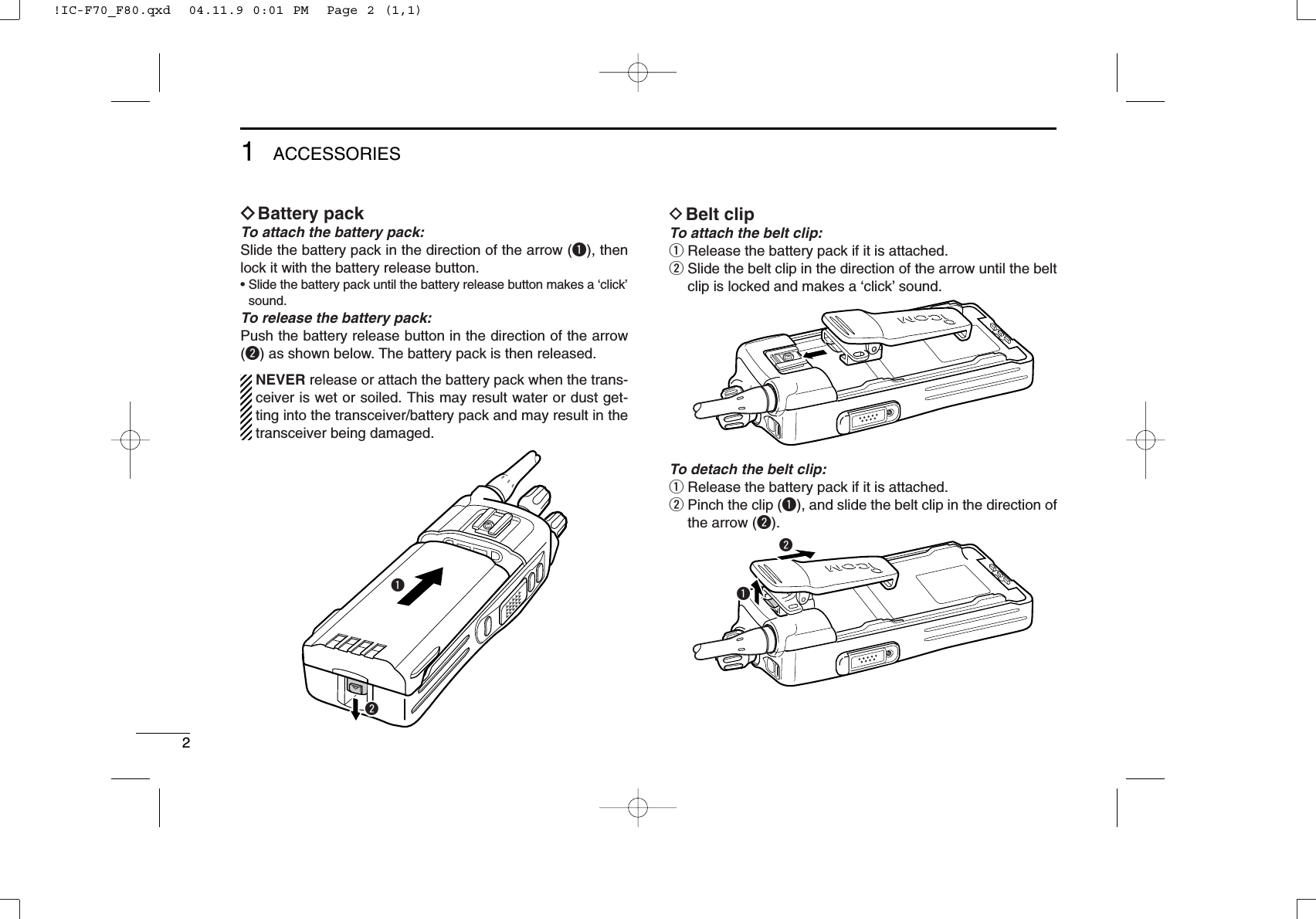
![226SPEAKER-MICROPHONE■Optional HM-184 descriptionNEVER immerse the connector in water. If the connectorbecomes wet, be sure to dry it BEFORE attaching it to thetransceiver.NOTE: The microphone is located at the top of thespeaker-microphone, as shown in the diagram above. Tomaximize the readability of your transmitted signal (voice),hold the microphone approx. 5 to 10 cm (2 to 4 inches)from your mouth, and speak in a normal voice level.■AttachmentAttach the connector of the speaker-microphone into the[SP/MIC] connector on the transceiver and tighten the screw.IMPORTANT: KEEP the [SP/MIC] jack cover attached(transceiver) when the speaker-microphone is not in use.Water will not get into the transceiver even if the cover isnot attached, however, the terminals (pins) will becomerusty, or the transceiver will function abnormally if the con-nector becomes wet.CAUTION: Attach the speaker-microphone s connector securely to prevent accidental dropping, or water intru-sion in the connector.!IC-F70_F80.qxd 04.11.9 0:02 PM Page 38 (1,1)](https://usermanual.wiki/ICOM-orporated/306200.User-Manual/User-Guide-952714-Page-27.png)