ICOM orporated 306200 VHF Transeiver User Manual IC F70 F80
ICOM Incorporated VHF Transeiver IC F70 F80
Contents
User Manual

INSTRUCTION MANUAL
This device complies with Part 15 of the FCC Rules. Operation is
subject to the condition that this device does not cause harmful
interference.
VHF TRANSCEIVER
!IC-F70_F80.qxd 04.10.26 5:41 PM Page a (1,1)
VHF TRANSCEIVER
!IC-F70_F80.qxd 04.10.26 5:41 PM Page a (1,1)
VHF TRANSCEIVER
!IC-F70_F80.qxd 04.10.26 5:41 PM Page a (1,1)
VHF TRANSCEIVER
IC-F9011B/S/T

i
EXPLICIT DEFINITIONS
WORD DEFINITION
RWARNING Personal injury, fire hazard or electric shock
may occur.
CAUTION Equipment damage may occur.
NOTE If disregarded, inconvenience only. No risk
of personal injury, fire or electric shock.
READ ALL INSTRUCTIONS carefully and com-
pletely before using the transceiver.
SAVE THIS INSTRUCTION MANUAL — This
instruction manual contains important operating instructions
for the IC-F9011B/F9011S/F9011T VHF TRANSCEIVER.
IMPORTANT
Icom, Icom Inc. and the logo are registered trademarks of Icom
Incorporated (Japan) in the United states, the United Kingdom, Germany,
France, Spain, Russia and/or other countries.
All other products or brands are registered trademarks or trademarks of their
respective holders.
ABOUT APCO PROJECT 25
This device made under license under one or more of the fol-
lowing US patents: #4,590,473, #4,636,791, #5,148,482,
#5,185,796, #5,271,017, #5,377,229.
The IMBE™ voice coding Technology embodied in this prod-
uct is protected by intellectual property rights including patent
rights, copyrights and trade secrets of Digital Voice Systems,
Inc. This voice coding Technology is licensed solely for use
within this Communications Equipment. The user of this
Technology is explicitly prohibited from attempting to decom-
pile, reverse engineer, or disassemble the Object Code, or in
any other way convert the Object Code into a human-readable
form. U.S. Pat. Nos. #5,870,405, #5,826,222, #5,754,974,
#5,701,390, #5,715,365, #5,649,050, #5,630,011, #5,581,656,
#5,517,511, #5,491,772, #5,247,579, #5,226,084, #5,195,166.
!IC-F70_F80.qxd 04.11.9 0:01 PM Page i (1,1)
FOR CLASS B UNINTENTIONAL RADIATORS
This equipment has been tested and found to comply with the limits for a Class B digital
device, pursuant to part 15 of the FCC Rules. These limits are designed to provide reason-
able protection against harmful interference in a residential installation. This equipment
generates, uses and can radiate radio frequency energy and, if not installed and used in
accordance with the instructions, may cause harmful interference to radio communications.
However, there is no guarantee that interference will not occur in a particular installation. If
this equipment does cause harmful interference to radio or television reception, which can
be determined by turning the equipment off and on, the user is encouraged to try to correct
the interference by one or more of the following measures:
• Reorient or relocate the receiving antenna.
• Increase the separation between the equipment and receiver.
• Connect the equipment into an outlet on a circuit different from that to which the re-
ceiver is connected.
• Consult the dealer or an experienced radio/TV technician for help.
A-6635H-2US-q

ii
RCAUTION! NEVER hold the transceiver so that the
antenna is very close to, or touching exposed parts of the
body, especially the face or eyes, while transmitting. The
transceiver will perform best if the microphone is 2 to 4 in. (5
to 10 cm) away from the lips and the transceiver is vertical.
RCAUTION! NEVER operate the transceiver with a
headset or other audio accessories at high volume levels.
RCAUTION! NEVER short the terminals of the bat-
tery pack.
DO NOT push PTT when not actually desiring to transmit.
AVOID using or placing the transceiver in direct sunlight or
in areas with temperatures below +22°F (–30°C) or above
+140°F (+60°C).
The basic operations, transmission and reception of the trans-
ceiver are guaranteed within the specified operating temper-
ature range. However, the LCD display may not be operate
correctly, or show an indication in the case of long hours of
operation, or after being placed in extremely cold areas.
DO NOT modify the transceiver for any reason.
KEEP the transceiver from the heavy rain, and Never
immerse it in the water. The transceiver construction is water
resistant, not waterproof.
The use of non-Icom battery packs/chargers may impair
transceiver performance and invalidate the warranty.
For U.S.A. only
CAUTION: Changes or modifications to this transceiver, not
expressly approved by Icom Inc., could void your authority to
operate this transceiver under FCC regulations.
PRECAUTION
!IC-F70_F80.qxd 04.11.9 0:01 PM Page ii (1,1)

iii
TABLE OF CONTENTS
IMPORTANT .................................................................................... i
EXPLICIT DEFINITIONS ................................................................. i
ABOUT APCO PROJECT 25 ........................................................... i
PRECAUTION ................................................................................. ii
TABLE OF CONTENTS .................................................................. iii
1 ACCESSORIES ..................................................................... 1–3
■Supplied accessories ............................................................. 1
■Accessory attachments .......................................................... 1
2 PANEL DESCRIPTION ......................................................... 4–7
■Front panel ............................................................................. 4
■Function display ..................................................................... 6
■Programmable function keys .................................................. 7
3BASIC OPERATION ..........................................................12–17
■Turning power ON ................................................................ 12
■Channel selection ................................................................. 12
■Call procedure ...................................................................... 13
■Receiving and transmitting ................................................... 13
■User set mode ......................................................................16
■Scrambler function ...............................................................17
4BATTERYCHARGING ......................................................18–20
■Battery charging ...................................................................18
■Battery caution .....................................................................18
■Optional battery chargers .....................................................19
5OPTIONALBATTERYCASE ..................................................21
■Optional battery case ...........................................................21
6SPEAKER-MICROPHONE ...................................................22
■Optional HM-184 description ................................................22
■ Attachmect ............................................................................22
7OPTIONS ............................................................................23-24
8 SAFETY TRAINING INFORMATION .................................25–26
!IC-F70_F80.qxd 04.11.9 0:01 PM Page iii (1,1)
1
1
ACCESSORIES
1
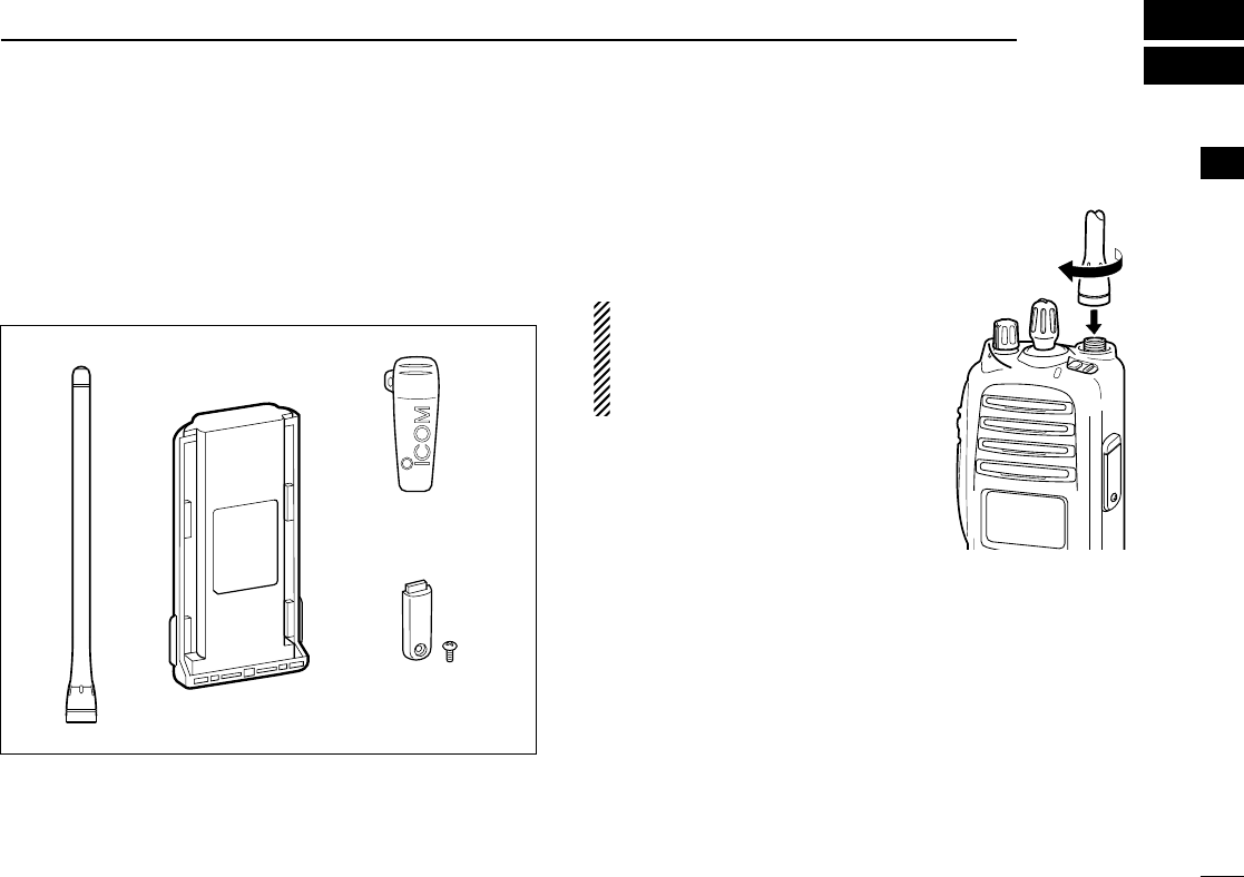
■Supplied accessories
The following accessories are supplied: Qty.
qFlexible antenna ……………………………………………1
wBattery pack …………………………………………………1
eBelt clip ………………………………………………………1
rJack cover (with screws) ………………………………1 set
■Accessory attachments
DFlexible antenna
Connect the supplied flexible anten-
na to the antenna connector.
CAUTION!
• NEVER HOLD by the antenna
when carrying the transceiver.
• Transmitting without an antenna
may damage the transceiver.
qwe
r
!IC-F70_F80.qxd 04.11.9 0:01 PM Page 1 (1,1)
2
1ACCESSORIES
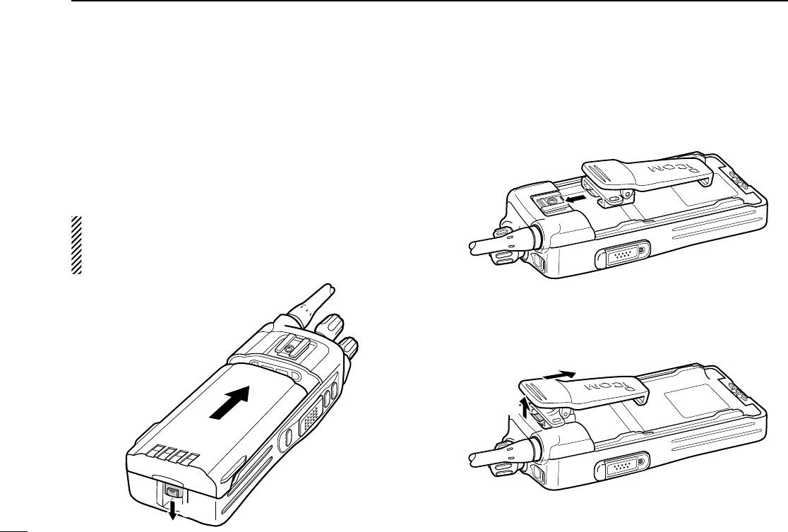
ïBattery pack
To attach the battery pack:
Slide the battery pack in the direction of the arrow (q), then
lock it with the battery release button.
• Slide the battery pack until the battery release button makes a ‘click’
sound.
To release the battery pack:
Push the battery release button in the direction of the arrow
(w) as shown below. The battery pack is then released.
NEVER release or attach the battery pack when the trans-
ceiver is wet or soiled. This may result water or dust get-
ting into the transceiver/battery pack and may result in the
transceiver being damaged.
DBelt clip
To attach the belt clip:
qRelease the battery pack if it is attached.
wSlide the belt clip in the direction of the arrow until the belt
clip is locked and makes a ‘click’ sound.
To detach the belt clip:
qRelease the battery pack if it is attached.
wPinch the clip (q), and slide the belt clip in the direction of
the arrow (w).
q
w
q
w
!IC-F70_F80.qxd 04.11.9 0:01 PM Page 2 (1,1)
3
1
ACCESSORIES
1
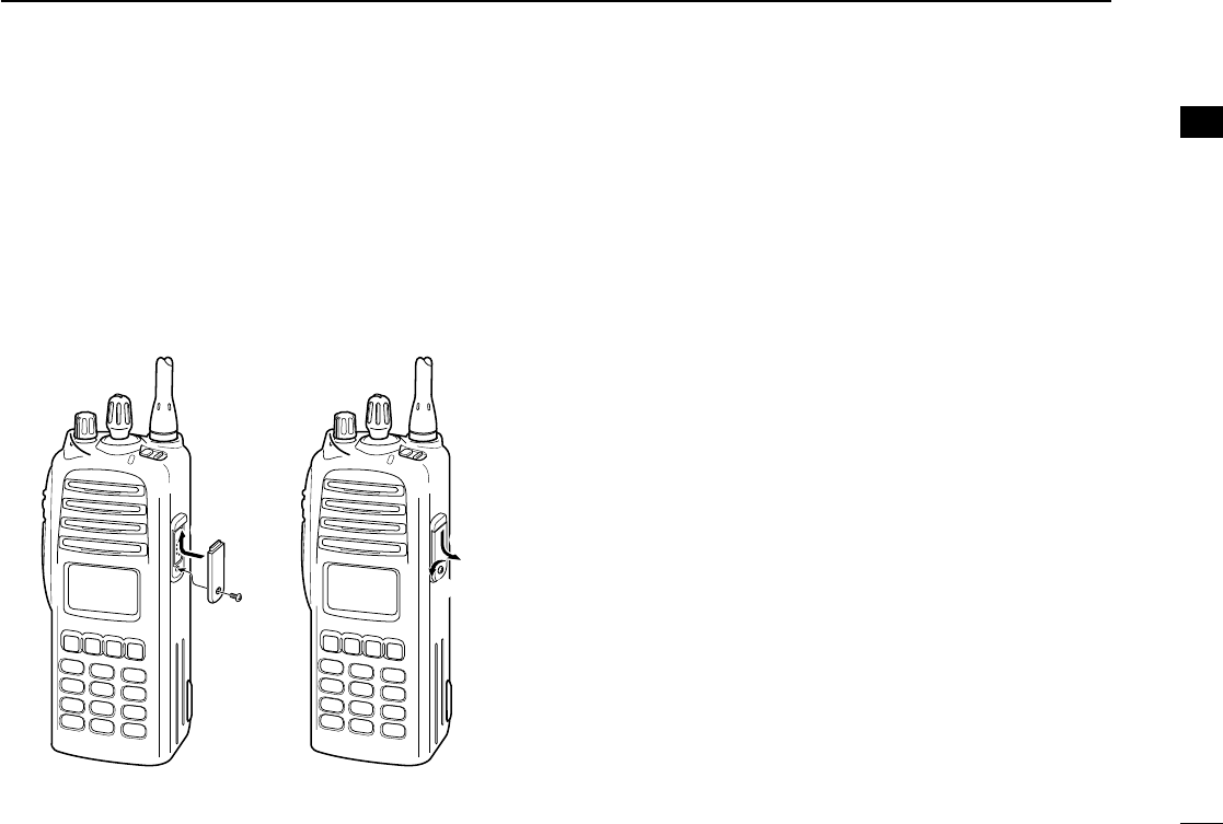
ïJack cover
Attach the jack cover when the optional speaker-microphone
is not used.
q
w
e
r
To attach the jack cover:
qInsert the jack cover into
the [SP MIC] connector.
wTighten the screw.
To detach the jack cover:
eUnscrew the screw with a
phillips screwdriver.
rDetach the jack cover for
the speaker-microphone
connection.
!IC-F70_F80.qxd 04.11.9 0:01 PM Page 3 (1,1)
4
2PANEL DESCRIPTION
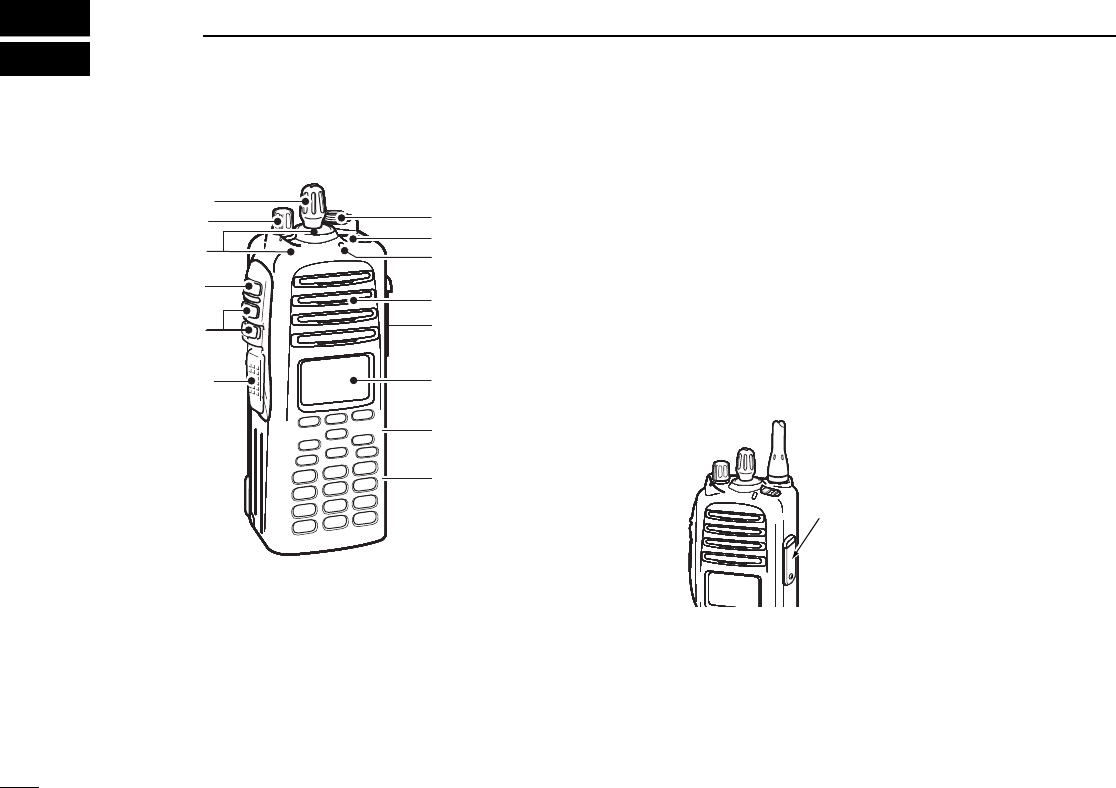
Front panel
A .VOLUME CONTROL [VOL]
Rotate to turn the power ON/OFF and adjusts the audio
level.
B .ROTARY SELECTOR
Rotate to select the pre-programmed memory channels or
the operating bank.
(Depending on the pre-setting)
C .ANTENNA CONNECTOR
Connects the supplied antenna.
D .EMERGENCY SWITCH
Push and hold for a specied period to transmit an emer-
gency call.
*Desired function can be programmed by your dealer. (p. 7)
E .BUSY/TRANSMIT INDICATOR
Lights green while receiving a signal, or when the
squelch is open.
Lights red while transmitting.
F .[SP/MIC] JACK
Connect the optional speaker-microphone.
G .FUNCTION DISPLAY (p. 6)
Displays a variety of information, such as an operating
channel number/name, 5-tone code, DTMF numbers and
audible condition, etc.
H .DEALER-PROGRAMMABLE KEYS
Desired functions can be programmed independently by
your dealer. (p. 7)
4
2PANEL DESCRIPTION
Front panel
A .VOLUME CONTROL [VOL]
Rotate to turn the power ON/OFF and adjusts the audio
level.
B .ROTARY SELECTOR
Rotate to select the pre-programmed memory channels or
the operating bank.
(Depending on the pre-setting)
C .ANTENNA CONNECTOR
Connects the supplied antenna.
D .EMERGENCY SWITCH
Push and hold for a specied period to transmit an emer-
gency call.
*Desired function can be programmed by your dealer. (p. 7)
E .BUSY/TRANSMIT INDICATOR
Lights green while receiving a signal, or when the
squelch is open.
Lights red while transmitting.
F .[SP/MIC] JACK
Connect the optional speaker-microphone.
G .FUNCTION DISPLAY (p. 6)
Displays a variety of information, such as an operating
channel number/name, 5-tone code, DTMF numbers and
audible condition, etc.
H .DEALER-PROGRAMMABLE KEYS
Desired functions can be programmed independently by
your dealer. (p. 7)
[SP/MIC] jack cover
NOTE: Attach the [SP/MIC] jack
cover when the optional speaker-
microphone is not used.
(See p. 3 for details)
[SP/MIC] jack cover
NOTE: Attach the [SP/MIC] jack
cover when the optional speaker-
microphone is not used.
(See p. 3 for details)
[SP/MIC] jack cover
NOTE: Attach the [SP/MIC] jack
cover when the optional speaker-
microphone is not used.
(See p. 3 for details)
[SP/MIC] jack cover
NOTE: Attach the [SP/MIC] jack
cover when the optional speaker-
microphone is not used.
(See p. 3 for details)
[SP/MIC] jack cover
NOTE: Attach the [SP/MIC] jack
cover when the optional speaker-
microphone is not used.
(See p. 3 for details)
[SP/MIC] jack cover
NOTE: Attach the [SP/MIC] jack
cover when the optional speaker-
microphone is not used.
(See p. 3 for details)
[SP/MIC] jack cover
NOTE: Attach the [SP/MIC] jack
cover when the optional speaker-
microphone is not used.
(See p. 3 for details)
[SP/MIC] jack cover
NOTE: Attach the [SP/MIC] jack
cover when the optional speaker-
microphone is not used.
(See p. 3 for details)
A
B C
D
E
Speaker
I
F
G
H
A
B C
D
E
Speaker
I
F
G
H
A
B C
D
E
Speaker
I
F
G
H
A
B C
D
E
Speaker
I
F
G
H
A
B C
D
E
Speaker
I
F
G
H
A
B C
D
E
Speaker
I
F
G
H
A
B C
D
E
Speaker
I
F
G
H
A
B C
D
E
Speaker
I
F
G
H
4
2PANEL DESCRIPTION
Front panel
A .VOLUME CONTROL [VOL]
Rotate to turn the power ON/OFF and adjusts the audio
level.
B .ROTARY SELECTOR
Rotate to select the pre-programmed memory channels or
the operating bank.
(Depending on the pre-setting)
C .ANTENNA CONNECTOR
Connects the supplied antenna.
D .EMERGENCY SWITCH
Push and hold for a specied period to transmit an emer-
gency call.
*Desired function can be programmed by your dealer. (p. 7)
E .BUSY/TRANSMIT INDICATOR
Lights green while receiving a signal, or when the
squelch is open.
Lights red while transmitting.
F .[SP/MIC] JACK
Connect the optional speaker-microphone.
G .FUNCTION DISPLAY (p. 6)
Displays a variety of information, such as an operating
channel number/name, 5-tone code, DTMF numbers and
audible condition, etc.
H .DEALER-PROGRAMMABLE KEYS
Desired functions can be programmed independently by
your dealer. (p. 7)
[SP/MIC] jack cover
NOTE: Attach the [SP/MIC] jack
cover when the optional speaker-
microphone is not used.
(See p. 3 for details)
[SP/MIC] jack cover
NOTE: Attach the [SP/MIC] jack
cover when the optional speaker-
microphone is not used.
(See p. 3 for details)
[SP/MIC] jack cover
NOTE: Attach the [SP/MIC] jack
cover when the optional speaker-
microphone is not used.
(See p. 3 for details)
[SP/MIC] jack cover
NOTE: Attach the [SP/MIC] jack
cover when the optional speaker-
microphone is not used.
(See p. 3 for details)
[SP/MIC] jack cover
NOTE: Attach the [SP/MIC] jack
cover when the optional speaker-
microphone is not used.
(See p. 3 for details)
[SP/MIC] jack cover
NOTE: Attach the [SP/MIC] jack
cover when the optional speaker-
microphone is not used.
(See p. 3 for details)
[SP/MIC] jack cover
NOTE: Attach the [SP/MIC] jack
cover when the optional speaker-
microphone is not used.
(See p. 3 for details)
[SP/MIC] jack cover
NOTE: Attach the [SP/MIC] jack
cover when the optional speaker-
microphone is not used.
(See p. 3 for details)
A
B C
D
E
Speaker
I
F
G
H
A
B C
D
E
Speaker
I
F
G
H
A
B C
D
E
Speaker
I
F
G
H
A
B C
D
E
Speaker
I
F
G
H
A
B C
D
E
Speaker
I
F
G
H
A
B C
D
E
Speaker
I
F
G
H
A
B C
D
E
Speaker
I
F
G
H
A
B C
D
E
Speaker
I
F
G
H
!IC-F70_F80.qxd 04.11.9 0:01 PM Page 4 (1,1)!IC-F70_F80.qxd 04.11.9 0:01 PM Page 4 (1,1)!IC-F70_F80.qxd 04.11.9 0:01 PM Page 4 (1,1)!IC-F70_F80.qxd 04.11.9 0:01 PM Page 4 (1,1)
J
K
L
M

5
2
PANEL DESCRIPTION
2
I . 10-KEYPAD (IC-F9011T only )
The keypad allows you to enter digits to:
• Select memory channels, tone channels and DTMF codes
(when in the DTMF code channel selection mode)
• Set TX codes
• Input text message for SDM operation
• Start up with a password
• Input the Individual ID code for digital operation.
J . MONITOR SWITCH
Mute and release the CTCSS (DTCS) or 2-tone squelch
mute. Open any squelch/deactivate any mute while
pushing this key. (LMR operation only)
Activates one of (or two of) the following functions on
each channel independently.
NOTE: The unmute condition (‘audible’conditions)
may automatically return to the mute condition
(‘inaudible’ condition) after a speciÞed period.
*Desired function can be programmed by your dealer. (p. 7)
K. PTT SWITCH [PTT]
Push and hold to transmit; release to receive.
Push to transmit the call during MSK operation, depend-
ing on the setting.
L . UP/DOWN SWITCHES
Push to select an operating channel.
Push to select a TX code channel after pushing
[TX CODE CH SELECT].
Push to select a DTMF channel after pushing [DTMF].
Push to select a scan group after pushing and holding
[SCAN].
Push to select a BIIS code, status number or SDM after
pushing [DIGITAL].
*Desired functions can be programmed independently by your
dealer. (p. 7)
!IC-F70_F80.qxd 04.11.9 0:01 PM Page 5 (1,1)!IC-F70_F80.qxd 04.11.9 0:01 PM Page 5 (1,1)!IC-F70_F80.qxd 04.11.9 0:01 PM Page 5 (1,1)!IC-F70_F80.qxd 04.11.9 0:01 PM Page 5 (1,1)
M. DEALER-PROGRAMMABLE SWITCH [2-Position SWITCH]
[Concentric SWITCH]
Desired functions can be programmed independently by your
dealer. (p. 7)

6
2PANEL DESCRIPTION
■Function display
qSIGNAL STRENGTH INDICATOR
Indicates relative signal strength level.
wLOW POWER INDICATOR
Appears when low output power is selected.
eAUDIBLE INDICATOR
➥Appears when the channel is in the ‘audible’(unmute)
condition.
➥Appears when the specified 2/5-tone/BIIS code is
received.
rCOMPANDER INDICATOR
Appears when the compander function is activated.
tSCRAMBLER INDICATOR
Appears when the voice scrambler function is activated.
yBELL INDICATOR
Appears/blinks when the specific 2/5-tone/BIIS code is
received, according to the pre-programming.
uCALL CODE MEMORY INDICATOR
Appears when the call code memory is selected.
iSCROLL INDICATOR
Appears when a received SDM including more than 12
characters is displayed.
oBATTERY INDICATOR
Appears or blinks when the battery power decreases to a
specified level.
!0 ALPHANUMERIC DISPLAY
Displays an operating channel number, channel name, Set
mode contents, DTMF code, etc.
The indication mode can be selected from 1 line or 2 lines.
Ask your dealer for details.
In this instruction manual, the LCD illustration is described
using the 2 lines indication mode.
!1 KEY INDICATOR
Indicate the programmed function of the front panel keys
([P1], [P2], [P3]).
XTXC SET
q t oiuyrew
!0
!1
!IC-F70_F80.qxd 04.11.9 0:02 PM Page 6 (1,1)

7
2
PANEL DESCRIPTION
■Programmable function keys
The following functions can be assigned to [DIAL]*, [UP],
[DOWN], [P1], [P2], [P3][<],[>]programmable function
keys.
Consult your Icom dealer or system operator for details con-
cerning your transceivers programming.
If the programmable function names are bracketed in the fol-
lowing explanations, the specific key is used to activate the
function depends on the programming.
CH UPAND DOWN KEYS
➥Push to select an operating channel.
➥Push to select a transmit code channel after pushing [TX
Code CH Select].
➥Push to select a DTMF channel after pushing [DTMF
Autodial].
➥Push to select a scan group after pushing and holding
[Scan A Start/Stop]/[Scan B Start/Stop].
➥Push to select an Individual ID code or Talkgroup ID code
after pushing [Individual] or [Talkgroup].
ZONE SELECT KEY
Push this key, then select the desired zone using [CH Up]/
[CH Down].
What is “zone”?— The desired channels are assigned
into a zone according to the intended use. For example,
‘Staff A’and ‘Staff B’are assigned into a “Business” zone,
and ‘John’and ‘Cindy’are assigned into a “Private” zone.
SCAN AKEY
➥This key’s operation depends on the Power ON Scan setting.
When the power ON scan function is turned OFF;
Push to start and cancel scanning operation. In case of
transmission during scan, cancels scanning.
When the power ON scan function is turned ON;
Push to pause scanning. Scanning resumes after a speci-
fied time period has passed. In case of transmission during
scan, pauses scanning. Scanning resumes after a specified
time period has passed after the transmission is finished.
➥Push and hold this key for 1 sec. to indicate the scan group,
then select the desired group using [CH Up]/[CH Down].
SCAN B KEY
➥Push to start and cancel scanning operation. In case of
transmission during scan, pauses scanning. Scanning
resumes after a specified time period has passed after the
transmission is finished.
➥Push and hold this key for 1 sec. to indicate the scan
group, then select the desired group using [CH Up]/
[CH Down].
2
!IC-F70_F80.qxd 04.11.9 0:02 PM Page 7 (1,1)

8
2PANEL DESCRIPTION
SCAN TAG KEY
Push to add or delete the selected channel to/from the scan
group.
PRIORITYCHANNELKEYS
➥Push to select Priority A or Priority B channel.
➥Push and hold [Prio A (Rewrite)] to rewrite the Prio A chan-
nel.
MR-CH 1/2/3/4 KEYS
Push to select an operating channel directly.
MONITOR KEY
➥Mute and release the CTCSS (DTCS) or 2-tone squelch
mute. Open any squelch/deactivate any mute while push-
ing this key.(LMR operation only)
LIGHT KEY
Push to turn the transceiver’s backlight ON temporarily when
the backlight function is turned OFF in user set mode.
LOCK KEY
Push and hold to electronically lock all programmable keys
except the following:
[Call] (incl. Call A and Call B), [Moni(Audi)] and [Emergency].
OUTPUT POWER SELECTION KEY
Push to select the transmit output power temporarily or per-
manently, depending on the pre-setting.
•Ask your dealer for the output power level for each selection.
C.TONE CHANNELENTER KEY
Push to select the continuous tone channel using [CH Up]/
[CH Down] to change the tone frequency/code setting. The
selected channel remains set as the continuous tone chan-
nel until another channel is designated as such.
TALK AROUND KEY
Turn the talk around function ON and OFF.
•The talk around function equalizes the transmit frequency to the
receive frequency for transceiver-to-transceiver communication.
WIDE/NARROW KEY
Push to toggle the IF bandwidth between wide and narrow.
!IC-F70_F80.qxd 04.11.9 0:02 PM Page 8 (1,1)

9
2
PANEL DESCRIPTION
DTMF AUTODIALKEY
➥Push to enter the DTMF channel selection mode. Then
select the desired DTMF channel using [CH Up]/[CH Down].
➥After selecting the desired DTMF channel, push this key to
transmit the DTMF code.
DTMF RE-DIALKEY
Push to transmit the last-transmitted DTMF code.
CALLKEYS
Push to transmit a 2-tone ID code.
•Call transmission is necessary before calling another station
depending on your signalling system.
•[Call A] and/or [Call B] may be available when your system employs
selective ‘Individual/Group’calls. Ask your dealer which call is
assigned to each key.
EMERGENCYKEYS
➥Push and hold for a specified period to transmit an emer-
gency call.
➥When [Emergency Single (Silent)] or [Emergency Repeat
(Silent)] is pushed, an emergency call is transmitted without
a beep emission and LCD indication change.
• If you want to cancel the emergency call, push (or push and
hold) the key again before transmitting the call.
• The emergency call is transmitted one time only or repeatedly
until receiving a control code depending on the pre-setting.
SURVEILLANCE KEY
Push to turn the surveillance function ON or OFF.
When this function is turned ON, the beep is not emitted and
the LCD backlight does not light when a signal is received or
a key is pushed, etc.
TX CODE CHANNELSELECT KEY
➥Push to enter the ID code channel selection mode directly.
Then set the desired channel using [CH Up]/[CH Down].
(p. 14)
TX CODE CHANNELUP/DOWN KEYS
Push to select a TX code channel directly.
2
!IC-F70_F80.qxd 04.11.9 0:02 PM Page 9 (1,1)

10
2PANEL DESCRIPTION
VOICE SCRAMBLER FUNCTION
Push to toggle the voice scrambler function ON and OFF.
COMPANDER KEY
Push to toggle the compander function ON and OFF.
The compander function reduces noise components from the
transmitted audio to provide clear communication.
USER SET MODE KEY
➥Push and hold to enter user set mode.
• During user set mode, push this key to select an item, and
change the value or condition using push [CH Up]/[CH Down].
➥Push and hold this key again to exit user set mode.
User set mode is also available via the ‘Power ON function.’
Refer to p. 16 also.
OPT OUT KEYS
Push to control the output signal level from the optional unit
connector.
TONE/NAC CH SELECT KEY
➥While in the analog mode operation, push to select the
continuous tone channel using [CH Up] or [CH Down] to
change the tone frequency/code setting.
➥While in the digital mode operation, push to select the NAC
channel using [CH Up] or [CH Down] to change the NAC
code setting.
➥While in the mixed (digital and analog) mode operation,
push to select the continuous tone channel using [CH Up]
or [CH Down] to change the tone frequency/code setting.
Then push this key to enter the setting. After that, the NAC
channel selection screen appears. Select the NAC chan-
nel using [CH Up] or [CH Down] to change the NAC code
setting. Then push this key to enter the setting.
!IC-F70_F80.qxd 04.11.9 0:02 PM Page 10 (1,1)

11
2
PANEL DESCRIPTION
2
DFor Digital mode operation only
INDIVIDUALKEY
➥Push to enter the individual ID code selection mode directly.
Then select the desired individual ID code using [CH Up]/
[CH Down]. (p. 15)
➥Push to stop the beep emission when receiving a matched
individual ID code.
TALKGROUPKEY
➥Push to enter the talkgroup ID code selection mode directly.
Then select the desired talkgroup ID code using [CH Up]/
[CH Down]. (p. 15)
➥Push to stop the beep emission when receiving a matched
talkgroup ID code.
!IC-F70_F80.qxd 04.11.9 0:02 PM Page 11 (1,1)
12
3BASIC OPERATION
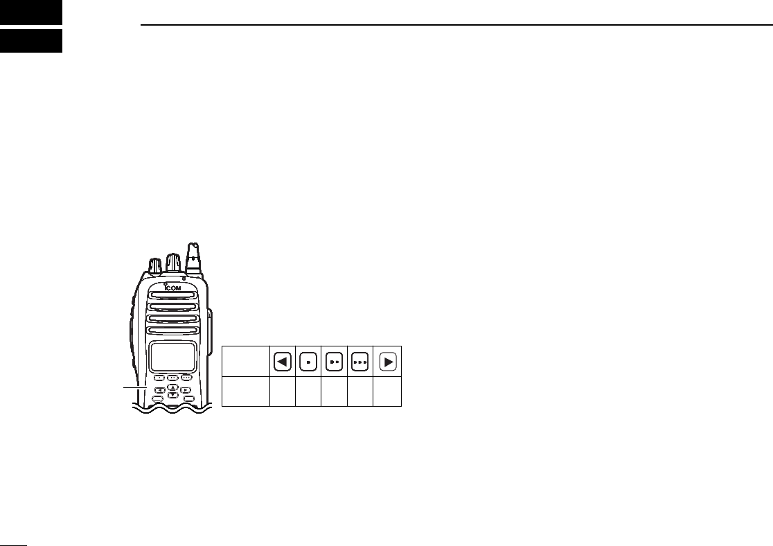
Turning power ON
Rotate [VOL] to turn the power ON.
If the transceiver is programmed for a start up password,
input the digit codes as directed by your dealer.
• 10-keypad* can be used for password input.
*IC-F9011T only:
• The keys as below can be used for password input:
The transceiver detects numbers in the same block as identical.
Therefore “01234” and “56789” are the same.
When the “PASSWORD” indication does not clear after
inputting 6 digits, the input code number may be incorrect.
Turn the power off and start over in this case.
Channel selection
Several types of channel selections are available. Methods
may differ according to your system set up.
NON-ZONE TYPE:
Push [CH Up] or [CH Down], or rotate [ROTARY SELECTOR]*
to select the desired operating channel, in sequence; or, push
one of [MR-CH 1] to [MR-CH 4] keys to select a channel
directly.
• Up to 16 pre-programmed channels can be selected via [ROTARY
SELECTOR].
ZONE TYPE:
Push [Zone] then push [CH Up] or [CH Down] or rotate
[ROTARY SELECTOR]* to select the desired zone.
AUTOMATIC SCAN TYPE:
Channel setting is not necessary for this type. When turning
power ON, the transceiver automatically starts scanning.
Scanning stops when receiving a call.
*Depending on the pre-setting.
12
3BASIC OPERATION
Turning power ON
Rotate [VOL] to turn the power ON.
If the transceiver is programmed for a start up password,
input the digit codes as directed by your dealer.
• 10-keypad* can be used for password input.
*IC-F9011T only:
• The keys as below can be used for password input:
The transceiver detects numbers in the same block as identical.
Therefore “01234” and “56789” are the same.
When the “PASSWORD” indication does not clear after
inputting 6 digits, the input code number may be incorrect.
Turn the power off and start over in this case.
Channel selection
Several types of channel selections are available. Methods
may differ according to your system set up.
NON-ZONE TYPE:
Push [CH Up] or [CH Down], or rotate [ROTARY SELECTOR]*
to select the desired operating channel, in sequence; or, push
one of [MR-CH 1] to [MR-CH 4] keys to select a channel
directly.
• Up to 16 pre-programmed channels can be selected via [ROTARY
SELECTOR].
ZONE TYPE:
Push [Zone] then push [CH Up] or [CH Down] or rotate
[ROTARY SELECTOR]* to select the desired zone.
AUTOMATIC SCAN TYPE:
Channel setting is not necessary for this type. When turning
power ON, the transceiver automatically starts scanning.
Scanning stops when receiving a call.
*Depending on the pre-setting.
KEY
NUMBER 0
5
4
9
3
8
2
7
1
6
[P2]/[P3]
KEY
NUMBER 0
5
4
9
3
8
2
7
1
6
[P2]/[P3]
KEY
NUMBER 0
5
4
9
3
8
2
7
1
6
[P2]/[P3]
KEY
NUMBER 0
5
4
9
3
8
2
7
1
6
[P2]/[P3]
KEY
NUMBER 0
5
4
9
3
8
2
7
1
6
[P2]/[P3]
KEY
NUMBER 0
5
4
9
3
8
2
7
1
6
[P2]/[P3]
KEY
NUMBER 0
5
4
9
3
8
2
7
1
6
[P2]/[P3]
KEY
NUMBER 0
5
4
9
3
8
2
7
1
6
[P2]/[P3]
12
3BASIC OPERATION
Turning power ON
Rotate [VOL] to turn the power ON.
If the transceiver is programmed for a start up password,
input the digit codes as directed by your dealer.
• 10-keypad* can be used for password input.
*IC-F9011T only:
• The keys as below can be used for password input:
The transceiver detects numbers in the same block as identical.
Therefore “01234” and “56789” are the same.
When the “PASSWORD” indication does not clear after
inputting 6 digits, the input code number may be incorrect.
Turn the power off and start over in this case.
Channel selection
Several types of channel selections are available. Methods
may differ according to your system set up.
NON-ZONE TYPE:
Push [CH Up] or [CH Down], or rotate [ROTARY SELECTOR]*
to select the desired operating channel, in sequence; or, push
one of [MR-CH 1] to [MR-CH 4] keys to select a channel
directly.
• Up to 16 pre-programmed channels can be selected via [ROTARY
SELECTOR].
ZONE TYPE:
Push [Zone] then push [CH Up] or [CH Down] or rotate
[ROTARY SELECTOR]* to select the desired zone.
AUTOMATIC SCAN TYPE:
Channel setting is not necessary for this type. When turning
power ON, the transceiver automatically starts scanning.
Scanning stops when receiving a call.
*Depending on the pre-setting.
KEY
NUMBER 0
5
4
9
3
8
2
7
1
6
[P2]/[P3]
KEY
NUMBER 0
5
4
9
3
8
2
7
1
6
[P2]/[P3]
KEY
NUMBER 0
5
4
9
3
8
2
7
1
6
[P2]/[P3]
KEY
NUMBER 0
5
4
9
3
8
2
7
1
6
[P2]/[P3]
KEY
NUMBER 0
5
4
9
3
8
2
7
1
6
[P2]/[P3]
KEY
NUMBER 0
5
4
9
3
8
2
7
1
6
[P2]/[P3]
KEY
NUMBER 0
5
4
9
3
8
2
7
1
6
[P2]/[P3]
KEY
NUMBER 0
5
4
9
3
8
2
7
1
6
[P2]/[P3]
!IC-F70_F80.qxd 04.11.9 0:02 PM Page 12 (1,1)!IC-F70_F80.qxd 04.11.9 0:02 PM Page 12 (1,1)!IC-F70_F80.qxd 04.11.9 0:02 PM Page 12 (1,1)!IC-F70_F80.qxd 04.11.9 0:02 PM Page 12 (1,1)
[<]/[>]/[P1]/
13
3
BASIC OPERATION
3
■Call procedure
When your system employs tone signaling (excluding CTCSS
and DTCS), the call procedure may be necessary prior to voice
transmission. The tone signalling employed may be a selec-
tive calling system which allows you to call specific station(s)
only and prevent unwanted stations from contacting you.
qSelect the desired TX code channel, 2-tone code,
Individual ID code* or Talkgroup ID code* according to
your System Operator’s instructions.
• This may not be necessary depending on programming.
• Refer to pgs. 11–13 for selection.
*Digital mode operation only.
wPush the call key (assigned to one of the dealer program-
mable keys; except for the Digital mode operation) or [PTT].
eAfter transmitting, the remainder of your communication
can be carried out in the normal fashion.
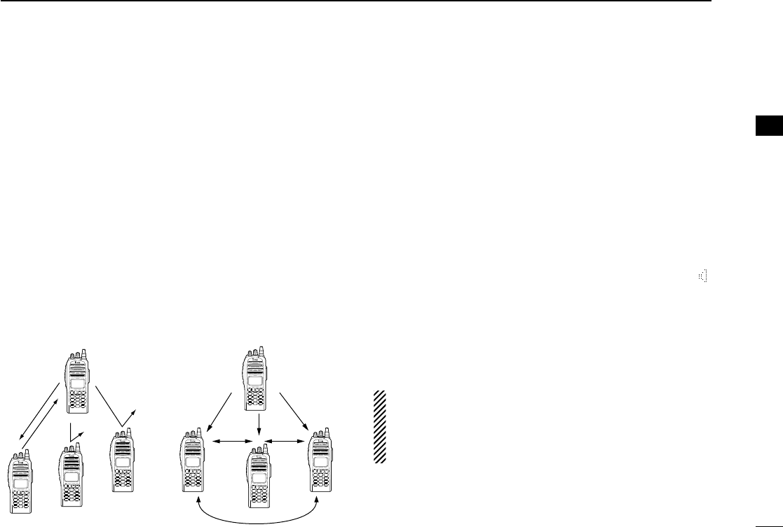
■Receiving and transmitting
Receiving:
qRotate [VOL] to turn the power ON.
wPush [CH Up] or [CH Down], or rotate [ROTARY SELEC-
TOR]* to select a channel in sequence.
*Depending on the pre-setting.
eWhen receiving a call, adjust the audio output level to a
comfortable listening level.
Transmitting:
Wait for the channel to become clear to avoid interference.
qPush [CALL] when initiating a call from your side.
• Coded audio may be heard from the transceiver, then “”
appears.
• This operation may not be necessary depending on your signal-
ing system. Ask your dealer for details.
wWhile pushing and holding [PTT], speak into the micro-
phone at your normal voice level.
eRelease [PTT] to return to receive.
IMPORTANT: To maximize the readability of your signal;
1. Pause briefly after pushing [PTT].
2. Hold the microphone 5 to 10 cm (2 to 4 inches) from
your mouth, then speak into the microphone at a normal
voice level.
Selective calling Non-selective calling
!IC-F70_F80.qxd 04.11.9 0:02 PM Page 13 (1,1)

14
3BASIC OPERATION
DTransmitting notes
• Transmit inhibit function
The transceiver has several inhibit functions which restrict
transmission under the following conditions:
- The channel is in mute condition (‘Inaudible’condition;
“”does not appear.)
- The channel is busy.
- Un-matched (or matched) CTCSS is received.
(Depending on the pre-setting.)
- Un-matched (or matched) NAC is received.*
(Depending on the pre-setting.)
- Un-matched (or matched) Individual ID or Talkgroup ID is
received.*
- The selected channel is a ‘receive only’channel.
*Digital mode operation only.
• Time-out timer
After continuous transmission for the pre-programmed time
period, the time-out timer is activated, causing the transceiv-
er to stop transmitting.
• Penalty timer
Once the time-out timer is activated, transmission is further
inhibited for a period determined by the penalty timer.
DTX code channel selection
If the transceiver has [TX Code CH Select] assigned to it, the
indication can be toggled between the operating channel
number (or name) and TX code channel number (or name).
When the TX code channel number (or name) is displayed,
[CH Up]or [CH Down] selects the TX code channel.
USING [TX CODE CH SELECT] KEY:
qPush [TX Code CH Select]—a TX code channel number
(or name) appears.
wPush [CH Up] or [CH Down] to select the desired TX code
channel.
ePush [Call] (or [PTT] during MSK operation) to transmit the
selected TX code.
USING [TX CODE CH UP]/[TX CODE CH DOWN] KEY:
If the transceiver has a [TX Code CH Up] or [TX Code CH
Down] key assignment, the programmed TX code channel
can be selected directly when pushed.
!IC-F70_F80.qxd 04.11.9 0:02 PM Page 14 (1,1)

15
3BASIC OPERATION
DIndividual ID code selection
(Digital mode operation only)
If the transceiver has [Individual] assigned to it, the indication
can be toggled between the operating channel number (or
name) and Individual ID code (or name). When the Individual
ID code (or name) is displayed, [CH Up] or [CH Down] selects
the desired Individual ID code.
qPush [Individual]—an Individual ID code (or name)
appears.
wPush [CH Up] or [CH Down] to select the desired
Individual ID code.
ePush [PTT] to transmit the selected Individual ID code.
rPush [Individual]—cancels the selected Individual ID code
(return to the pre-set Talkgroup ID code in the channel.)
DTalkgroup ID code selection
(Digital mode operation only)
If the transceiver has [Talkgroup] assigned to it, the indication
can be toggled between the operating channel number (or
name) and Talkgroup ID code (or name). When the Talkgroup
ID code (or name) is displayed, [CH Up] or [CH Down] selects
the desired Talkgroup ID code.
qPush [Talkgroup]—a Talkgroup ID code (or name)
appears.
wPush [CH Up] or [CH Down] to select the desired
Talkgroup ID code.
ePush [PTT] to transmit the selected Talkgroup ID code.
rChange the channel—cancels the selected Talkgroup ID
code (return to the pre-set Talkgroup ID code in the chan-
nel.)
DDTMF transmission
If the transceiver has [DTMF Autodial] assigned to it, the
automatic DTMF transmission function is available. Up to 8
DTMF channels are available.
TO SELECT A TX CODE:
qPush [DTMF Autodial]—a DTMF channel appears.
wPush [CH Up] or [CH Down] to select the desired DTMF
channel.
ePush [DTMF Autodial] to transmit the DTMF code in the
selected DTMF channel.
!IC-F70_F80.qxd 04.11.9 0:02 PM Page 16 (1,1)
16
3
BASIC OPERATION
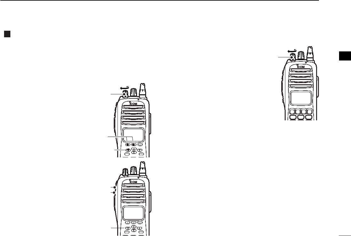
User set mode
User set mode is accessed at power ON and allows you to
set seldom-changed settings. In this case you can “cus-
tomize” the transceiver operation to suit your preferences and
operating style.
Entering the user set mode:
While pushing and holding [P1]
and [P2], rotate [VOL] to turn
the power ON. Then, push and
hold [<] to enter user set
mode.
Push [<] several times to
select the appropriate item.
Then, push [Up] or [Down] to
set the desired level/condition.
• Available set mode functions are
Backlight, LCD Contrast, Beep,
Beep Level, SQL Level, AF Min
Level, Mic Gain, Vox Gain, Vox
Delay and Battery Voltage.
Rotate [VOL] to turn the power
OFF to exit set mode.
User set mode is also available via
a programmable key. Please refer
to p. 10 [User Set Mode] section.
[<]
[P1]/[P2]
[VOL]
[<]
[P1]/[P2]
[VOL]
[<]
[P1]/[P2]
[VOL]
[<]
[P1]/[P2]
[VOL]
[<]
[P1]/[P2]
[VOL]
[<]
[P1]/[P2]
[VOL]
[<]
[P1]/[P2]
[VOL]
[<]
[P1]/[P2]
[VOL]
[<]
[Down]
[Up]
[<]
[Down]
[Up]
[<]
[Down]
[Up]
[<]
[Down]
[Up]
[<]
[Down]
[Up]
[<]
[Down]
[Up]
[<]
[Down]
[Up]
[<]
[Down]
[Up]
[VOL][VOL][VOL][VOL][VOL][VOL][VOL][VOL]
[<]
[P1]/[P2]
[VOL]
[<]
[P1]/[P2]
[VOL]
[<]
[P1]/[P2]
[VOL]
[<]
[P1]/[P2]
[VOL]
[<]
[P1]/[P2]
[VOL]
[<]
[P1]/[P2]
[VOL]
[<]
[P1]/[P2]
[VOL]
[<]
[P1]/[P2]
[VOL]
[<]
[Down]
[Up]
[<]
[Down]
[Up]
[<]
[Down]
[Up]
[<]
[Down]
[Up]
[<]
[Down]
[Up]
[<]
[Down]
[Up]
[<]
[Down]
[Up]
[<]
[Down]
[Up]
[VOL][VOL][VOL][VOL][VOL][VOL][VOL][VOL]
3
!IC-F70_F80.qxd 04.11.9 0:02 PM Page 17 (1,1)
3
!IC-F70_F80.qxd 04.11.9 0:02 PM Page 17 (1,1)
3
!IC-F70_F80.qxd 04.11.9 0:02 PM Page 17 (1,1)
3
!IC-F70_F80.qxd 04.11.9 0:02 PM Page 17 (1,1)

17
3BASIC OPERATION
■Scrambler function
The voice scrambler function provides private communication
between stations. The frequency inversion type is equipped
to all versions.
qPush [Scrambler] to turn the scrambler function ON.
• “” appears.
wPush [Scrambler] again to turn the scrambler function
OFF.
• “” disappears.
!IC-F70_F80.qxd 04.11.9 0:02 PM Page 18 (1,1)

18
4BATTERYCHARGING
■Battery charging
Prior to using the transceiver for the first time, the battery
pack must be fully charged for optimum life and operation.
CAUTION: To avoid damage to the transceiver, turn the
power OFF while charging.
• Recommended temperature range for charging:
+10°C to +40°C (+50°F to +104°F)
• Use the specified chargers (BC-119N and BC-121N).
NEVER use another manufacture’s charger.
• Use the specified AC adapter. NEVER use another manu-
facture’s adapter.
■Battery caution
RDANGER Charge the specified Icom batteries only.
Only tested and approved for use with genuine Icom batter-
ies. Fire and/or explosion may occur when a third party bat-
tery pack or counterfeit product is charged.
CAUTION! NEVER insert battery pack/transceiver (with the
battery pack attached) in a wet or soiled condition into the
charger. This may result in corrosion of the charger terminals
or damage to the charger. The charger is not waterproof and
water can easily get into it.
NEVER incinerate used battery packs. Internal battery gas
may cause an explosion.
NEVER immerse the battery pack in water. If the battery
pack becomes wet, be sure to wipe it dry BEFORE attaching
it to the transceiver.
NEVER short the terminals of the battery pack. Also, current
may flow into nearby metal objects, such as a necklace, etc.
Therefore, be careful when carrying with, or placing near
metal objects, carrying in handbags, etc.
AVOID leaving the battery pack in a fully charged, or completely
discharged condition for long time. It causes shorter battery life.
In case of leaving the battery pack unused for a long time, it
must be kept safely after discharge, or use the battery until the
battery indicator appears, then remove it from the transceiver.
If your battery pack seems to have no capacity even after
being charged, fully charge the battery pack again. If the bat-
teries still do not retain a charge (or very little), new battery
pack must be purchased.
Recommendation:
Charge the supplied battery pack for a maximum of
up to 10 hours. Li-Ion batteries are different from Ni-
Cd batteries in that it is not necessary to completely
charge and discharge them to prolong the battery life.
Therefore, charging the battery in intervals, and not
for extended periods is recommended.
!IC-F70_F80.qxd 04.11.9 0:02 PM Page 32 (1,1)
19
4
BATTERY CHARGING
4
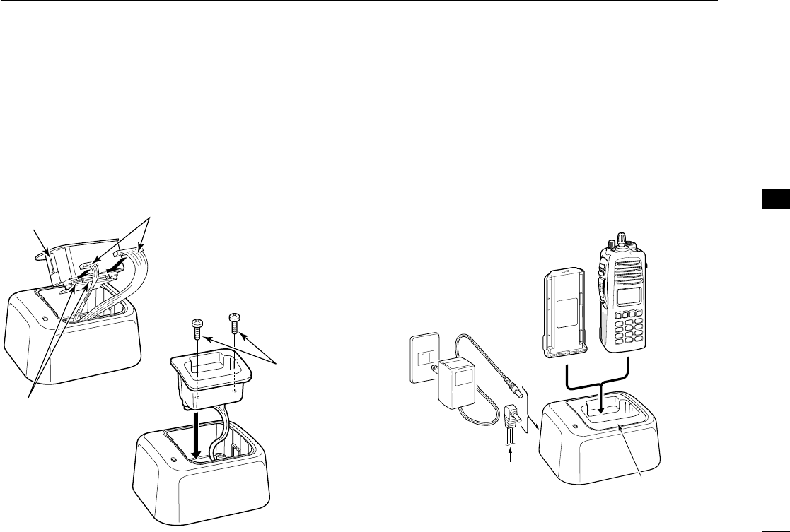
■Optional battery chargers
ïAD-110 installation
qInstall the AD-110 desktop charger adapter into the holder
space of the BC-119N/BC-121N.
wConnect the plugs of the BC-119N/BC-121N to the AD-110
desktop charger adapter with the connector, then install
the adapter into the charger with the supplied screws.
ïRapid charging with the BC-119N+AD-110
The optional BC-119N provides rapid charging of battery
packs. The following items are additionally required.
• AD-110 charger adapter
• An AC adapter (may be supplied with BC-119N depending
on version) or the DC power cable (OPC-515L/CP-17L).
AD-110 charger
adapter is installed
in BC-119N.
AC adapter
(Not supplied with
some versions.)
Optional OPC-515L (for 13.8 V
power source) or CP-17L (for 12
V cigarette lighter socket) can be
used instead of the AC adapter.
BP-254
TRANSCEIVER
AD-110
Connectors
q
Screws supplied
with the charger
adapter
Plugs
w
!IC-F70_F80.qxd 04.11.9 0:02 PM Page 33 (1,1)
20
4BATTERYCHARGING
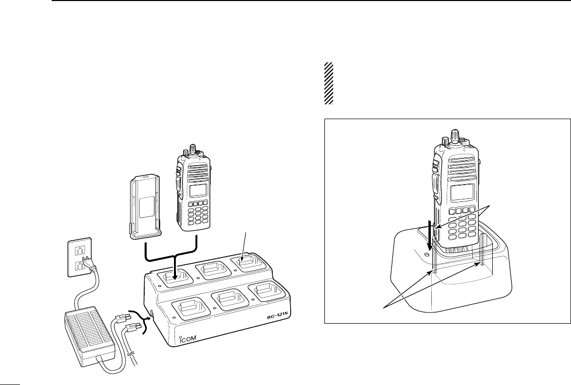
ïRapid charging with the BC-121N+AD-100
The optional BC-121N allows up to 6 battery packs to be
charged simultaneously. The following items are additionally
required.
• Six AD-100 charger adapters
• An AC adapter (BC-124) or the DC power cable (OPC-656)
IMPORTANT!: Battery charging
Ensure the guide lobs on the battery pack are correctly
aligned with the guide rails inside the charger adapter.
(This illustration is described with the BC-119N.)
Lobs
Guide rails
MULTI-CHARGER
AD-110 charger
adapters are installed
in each slot.
DC power cable (OPC-656)
(Connect with the DC power supply;
13.8 V/at least 7 A
)
AC adapter
(Purchased
separately)
TRANSCEIVER
BP-254
!IC-F70_F80.qxd 04.11.9 0:02 PM Page 34 (1,1)
21
5
OPTIONALBATTERYCASE
5
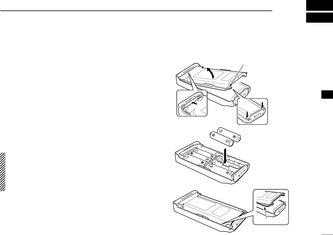
■Optional battery case
When using the optional battery case attached to the trans-
ceiver, install 6 ×AA (LR6) size alkaline batteries as illustrated
at right. The BP-237 meets JIS waterproof specification grade
4.
qHook your finger under the latch, and open the cover in the
direction of the arrow (q). (Fig.1)
wThen, install 6 ×AA (LR6) size alkaline batteries. (Fig.2)
• Install the alkaline batteries only.
• Be sure to observe the correct polarity.
• Do not pin the ribbon under the batteries.
eClose the cover by fitting in the direction of the arrow (w)
first, then check the latch is in place (e). (Fig.1)
• Be sure the gasket and the ribbon are set correctly, and do not
protrude from the battery case. (Fig.3)
CAUTION:
•When installing batteries, make sure they are all the same
brand, type and capacity. Also, do not mix new and old
batteries together.
•Keep battery contacts clean. It’s a good idea to clean bat-
tery terminals once a week.
q
BP-237
Fig.1
Fig.2
Fig.3
e
Gasket
Latch
w
!IC-F70_F80.qxd 04.11.9 0:02 PM Page 35 (1,1)
22
6SPEAKER-MICROPHONE
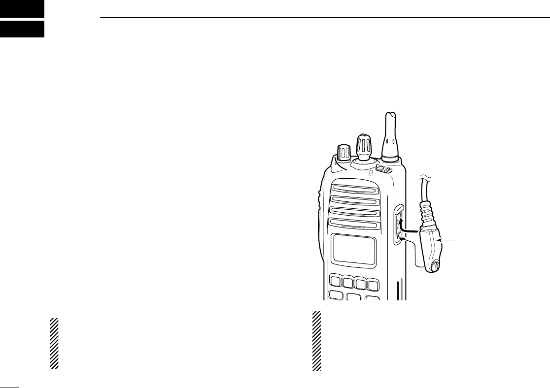
■Optional HM-184 description
NEVER immerse the connector in water. If the connector
becomes wet, be sure to dry it BEFORE attaching it to the
transceiver.
NOTE: The microphone is located at the top of the
speaker-microphone, as shown in the diagram above. To
maximize the readability of your transmitted signal (voice),
hold the microphone approx. 5 to 10 cm (2 to 4 inches)
from your mouth, and speak in a normal voice level.
■Attachment
Attach the connector of the speaker-microphone into the
[SP/MIC] connector on the transceiver and tighten the screw.
IMPORTANT: KEEP the [SP/MIC] jack cover attached
(transceiver) when the speaker-microphone is not in use.
Water will not get into the transceiver even if the cover is
not attached, however, the terminals (pins) will become
rusty, or the transceiver will function abnormally if the con-
nector becomes wet.
CAUTION: Attach the
speaker-microphone s
connector securely to
prevent accidental
dropping, or water intru-
sion in the connector.
!IC-F70_F80.qxd 04.11.9 0:02 PM Page 38 (1,1)

23
7
OPTIONS
7
DBATTERY PACK
•BP-254 Li-Ion
BATTERYPACK
7.4 V/3040 mAh Li-Ion battery pack, allows more than 8
hours operation. The same as supplied with the transceiver.
•BP-237
BATTERY CASE
Battery case for 6 ×AA (LR6) alkaline cells.
DCHARGERS
•BC-119N
DESKTOP CHARGER
+ AD-110
CHARGER ADAPTER
+ BC-145
AC ADAPTER
For rapid charging of battery packs. An AC adapter is sup-
plied with the charger depending on versions. Charging
time: approx. 4 hours when BP-254 is attached.
•BC-121N
MULTI
-
CHARGER
+ AD-110
CHARGER ADAPTER
(6
pcs.)
+ BC-124
AC ADAPTER
For rapid charging of up to 6 battery packs (six AD-100’s are
required) simultaneously. An AC adapter should be pur-
chased separately. Charging time: approx. 4 hours when
BP-254 is attached.
DBELT CLIPS
•MB-115
BELTCLIP
Exclusive alligator-type belt clip. The same as supplied with
the transceiver.
DOPTIONAL UNITS
• UT-124R MAN DOWN UNIT
• UT-125
ENCRIPTION UNIT
DDC CABLES
•CP-17L
CIGARETTE LIGHTER CABLE
Allows charging of the battery pack through a 12 V cigarette
lighter socket. (For BC-119N)
•OPC-515L/OPC-656
DC POWER CABLES
Allows charging of the battery pack using a 13.8 V power
source instead of the AC adapter.
OPC-515L: For BC-119N
OPC-656 : For BC-121N
•OPC-1862
INTERFACECABLE
Provides advanced operation.
!IC-F70_F80.qxd 04.11.9 0:02 PM Page 39 (1,1)

24
7OPTIONS
DOTHER OPTIONS
•HM-184
SPEAKER
-
MICROPHONE
Full-sized waterproof (JIS grade 7; 1m/30 min.) speaker-
microphone including alligator type clip to attach to your shirt
or collar, etc.
•FA-S25V/FA-S65V/FA-S66V
FLEXIBLE ANTENNAS
FA-S25V: 136–148 MHz
FA-S65V: 148–160 MHz
FA-S66V: 160–174 MHz
•FA-S67VC
CUT ANTENNAS
FA-S67VC: 136–174 MHz
Some options may not available in some countries. Please ask your
dealer for details.
!IC-F70_F80.qxd 04.11.9 0:02 PM Page 40 (1,1)

25
8SAFETYTRAINING INFORMATION
Your Icom radio generates RF electromagnetic
energy during transmit mode. This radio is
designed for and classified as “Occupational
Use Only”, meaning it must be used only during
the course of employment by individuals aware
of the hazards, and the ways to minimize such
hazards. This radio is NOT intended for use by the “General
Population” in an uncontrolled environment.
This radio has been tested and complies with the FCC RF
exposure limits for “Occupational Use Only”. In addition, your
Icom radio complies with the following Standards and
Guidelines with regard to RF energy and electromagnetic
energy levels and evaluation of such levels for exposure to
humans:
• FCC OET Bulletin 65 Edition 97-01 Supplement C,
Evaluating Compliance with FCC Guidelines for Human
Exposure to Radio Frequency Electromagnetic Fields.
• American National Standards Institute (C95.1-1992),
IEEE Standard for Safety Levels with Respect to Human
Exposure to Radio Frequency Electromagnetic Fields, 3
kHz to 300 GHz.
• American National Standards Institute (C95.3-1992),
IEEE Recommended Practice for the Measurement of
Potentially Hazardous Electromagnetic Fields– RF and
Microwave.
• The accessories (antennas, batteries, belt clips, speaker-
microphone, etc. that is listed on Pages 39–40) are
authorized for use with this product. Use of accessories
other than those specified may result in RF exposure lev-
els exceeding the FCC requirements for wireless RF
exposure.
To ensure that your expose to RF electro-
magnetic energy is within the FCC allow-
able limits for occupational use, always
adhere to the following guidelines:
• DO NOT operate the radio without a proper antenna
attached, as this may damaged the radio and may also
cause you to exceed FCC RF exposure limits. A proper
antenna is the antenna supplied with this radio by the
manufacturer or antenna specifically authorized by the
manufacturer for use with this radio.
• DO NOT transmit for more than 50% of total radio use
time (“50% duty cycle”). Transmitting more than 50% of
the time can cause FCC RF exposure compliance
requirements to be exceeded. The radio is transmitting
when the TX indicator lights red. You can cause the radio
to transmit by pressing the “PTT” switch or VOX function.
• ALWAYS keep the antenna at least 2.5 cm (1 inch) away
from the body when transmitting and only use the Icom
belt-clips listed on page 39 when attaching the radio to
your belt, etc., to ensure FCC RF exposure compliance
requirements are not exceeded. To provide the recipients
of your transmission the best sound quality, hold the
antenna at least 5 cm (2 inches) from your mouth, and
slightly off to one side.
The information listed above provides the user with the infor-
mation needed to make him or her aware of RF exposure,
and what to do to assure that this radio operates with the
FCC RF exposure limits of this radio.
CAUTION
WARNING
!IC-F70_F80.qxd 04.11.9 0:02 PM Page 42 (1,1)

26
8
SAFETYTRAINING INFORMATION
8
Electromagnetic Interference/Compatibility
During transmissions, your Icom radio generates RF energy
that can possibly cause interference with other devices or
systems. To avoid such interference, turn off the radio in
areas where signs are posted to do so. DO NOT operate the
transmitter in areas that are sensitive to electromagnetic radi-
ation such as hospitals, aircraft, and blasting sites.
Occupational/Controlled Use
The radio transmitter is used in situations in which persons
are exposed as consequence of their employment provided
those persons are fully aware of the potential for exposure
and can exercise control over their exposure.
!IC-F70_F80.qxd 04.11.9 0:02 PM Page 43 (1,1)

1-1-32 Kamiminami, Hirano-ku, Osaka 547-0003, Japan
A-6418D-1US
Printed in Japan
©2008 Icom Inc.
!IC-F70_F80.qxd 04.11.9 0:02 PM Page Z (1,1)