ICOM orporated 307400 VHF Air Band Transceiver User Manual IC A14 S 2 indd
ICOM Incorporated VHF Air Band Transceiver IC A14 S 2 indd
Contents
- 1. Manual
- 2. Revised User Manual
- 3. User manual
Revised User Manual
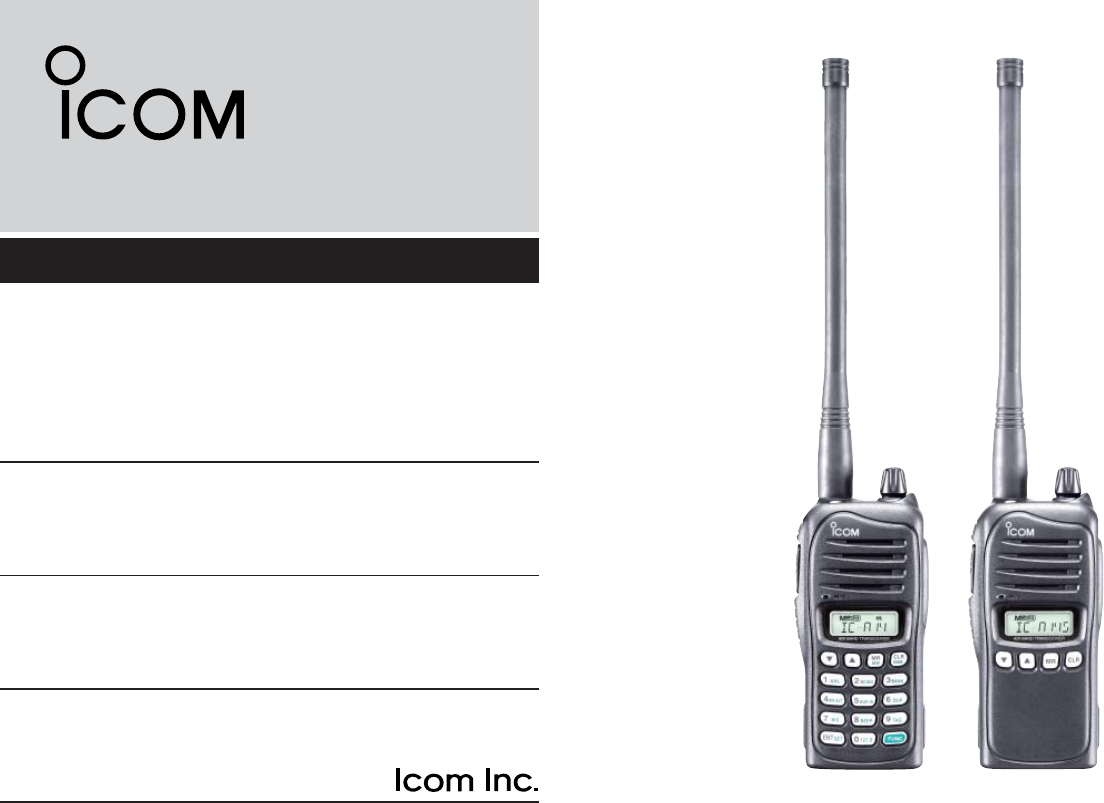
INSTRUCTION MANUAL
iA14
iA14S
VHF AIR BAND TRANSCEIVER
This device complies with Part 15 of the FCC
Rules. Operation is subject to the condition
that this device does not cause harmful inter-
ference.
YIC-A14 YIC-A14S

i
SAFETY TRAINING INFORMATION
WARNING
Your Icom radio generates RF electromagnetic energy during
transmit mode. This radio is designed for and classifi ed as
“Occupational Use Only”, meaning it must be used only dur-
ing the course of employment by individuals aware of the
hazards, and the ways to minimize such hazards. This radio
is NOT intended for use by the “General Population” in an un-
controlled environment.
This radio has been evaluated for compliance at the distance of 2.5 cm with
the FCC RF exposure limits for “Occupational Use Only”. In addition, your Icom
radio complies with the following Standards and Guidelines with regard to RF
energy and electromagnetic energy levels and evaluation of such levels for ex-
posure to humans:
• FCC OET Bulletin 65 Edition 97-01 Supplement C, Evaluating Com-
pliance with FCC Guidelines for Human Exposure to Radio Frequency
Electromagnetic Fields.
• American National Standards Institute (C95.1-1992), IEEE Standard
for Safety Levels with Respect to Human Exposure to Radio Frequency
Electromagnetic Fields, 3 kHz to 300 GHz.
• American National Standards Institute (C95.3-1992), IEEE Recom-
mended Practice for the Measurement of Potentially Hazardous Electro-
magnetic Fields– RF and Microwave.
• The following accessories are authorized for use with this product. Use
of accessories other than those specifi ed may result in RF exposure lev-
els exceeding the FCC requirements for wireless RF exposure.; Belt Clip
(MB-94/96F) and Rechargeable Li-ion Battery Pack (BP-230N/232N/BP-
232H).
To ensure that your expose to RF electromagnetic en-
ergy is within the FCC allowable limits for occupational
use, always adhere to the following guidelines:
• DO NOT operate the radio without a proper antenna attached, as this
may damage the radio and may also cause you to exceed FCC RF ex-
posure limits. A proper antenna is the antenna supplied with this radio by
the manufacturer or antenna specifi cally authorized by the manufacturer
for use with this radio.
• DO NOT transmit for more than 50% of total radio use time (“50% duty
cycle”). Transmitting more than 50% of the time can cause FCC RF ex-
posure compliance requirements to be exceeded. The radio is transmit-
ting when “ ” appears on the function display. You can cause the radio
to transmit by pressing the “PTT” switch.
• ALWAYS keep the antenna at least 2.5 cm (1 inch) away from the body
when transmitting and only use the Icom belt-clips which are listed on
page 38 when attaching the radio to your belt, etc., to ensure FCC RF
exposure compliance requirements are not exceeded. To provide the re-
cipients of your transmission the best sound quality, hold the antenna at
least 5 cm (2 inches) from your mouth, and slightly off to one side.
The information listed above provides the user with the information needed
to make him or her aware of RF exposure, and what to do to assure that this
radio operates with the FCC RF exposure limits of this radio.
Electromagnetic Interference/Compatibility
During transmissions, your Icom radio generates RF energy that can possibly
cause interference with other devices or systems. To avoid such interference,
turn off the radio in areas where signs are posted to do so. DO NOT operate
the transmitter in areas that are sensitive to electromagnetic radiation such as
hospitals and blasting sites.
Occupational/Controlled Use
The radio transmitter is used in situations in which persons are exposed as
consequence of their employment provided those persons are fully aware of
the potential for exposure and can exercise control over their exposure.
CAUTION
ii
FOREWORD
Thank you for purchasing this Icom product. The IC-A14/S
VHF AIR BAND TRANSCEIVER is designed and built with Icom’s
state of the art technology and craftsmanship. With proper
care this product should provide you with years of trouble-
free operation.
IMPORTANT
READ ALL INSTRUCTIONS carefully and completely
before using the transceiver.
SAVE THIS INSTRUCTION MANUAL— This in-
struction manual contains important operating instructions for
the IC-A14/S.
EXPLICIT DEFINITIONS
WORD DEFINITION
RDANGER! Personal death, serious injury or an explosion may
occur.
RWARINING! Personal injury, fi re hazard or electric shock may
occur.
CAUTION Equipment damage may occur.
NOTE If disregarded, inconvenience only. No risk of per-
sonal injury, fi re or electric shock.
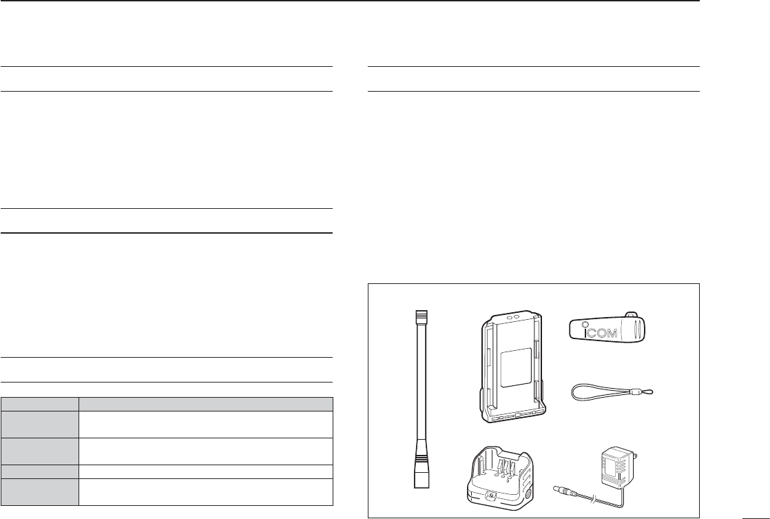
SUPPLIED ACCESSORIES
The following accessories are supplied with the transceiver.
Qty.
q Flexible antenna .............................................................. 1
w Battery pack* ................................................................... 1
e Belt clip ........................................................................... 1
r Hand strap ...................................................................... 1
t Battery charger† .............................................................. 1
y AC adapter† .................................................................... 1
*Battery case is supplied with some versions.
†Not supplied with the battery case supplied versions.
qw*
t
†
y
†
e
r

RDANGER! NEVER short the terminals of the battery
pack. Also, current may fl ow into nearby metal objects, such
as a necklace, etc. Therefore, be careful when carrying with,
or placing near metal objects, carrying in handbags, etc.
RDANGER! Use and charge only specifi ed Icom battery
packs with Icom radios or Icom chargers. Only Icom battery
packs are tested and approved for use with Icom radios or
charged with Icom chargers. Using third-party or counterfeit
battery packs or chargers may cause smoke, fi re, or cause
the battery to burst.
R WARNING! NEVER hold the transceiver so that the
antenna is very close to, or touching exposed parts of the
body, especially the face or eyes, while transmitting. The
transceiver will perform best if the microphone is 5 to 10 cm
(2 to 4 inches) away from the lips and the transceiver is ver-
tical.
R WARNING! NEVER operate the transceiver with a
headset or other audio accessories at high volume levels.
Hearing experts advise against continuous high volume op-
eration. If you experience a ringing in your ears, reduce the
volume level or discontinue use.
CAUTION: DO NOT use harsh solvents such as benzine
or alcohol to clean the transceiver, because they can dam-
age the transceiver’s surfaces.
DO NOT allow children to play with any radio equipment
containing a transmitter.
DO NOT operate the transceiver near unshielded electrical
blasting caps or in an explosive atmosphere.
DO NOT using or placing the transceiver in direct sunlight
or in areas with temperatures below –10°C (+14°F) or above
+60°C (+140°F).
KEEP the transceiver away from the heavy rain, and
NEVER immerse it in the water. The transceiver construc-
tion is water resistant, not waterproof.
CLEAN and wipe dry the battery terminals after using the
transceiver in wet conditions. The terminals may rust if not
dried.
iii
PRECAUTIONS
Icom, Icom Inc. and the Icom logo are registered trademarks of Icom Incor-
porated (Japan) in Japan, the United States, the United Kingdom, Germany,
France, Spain, Russia and/or other countries.
FCC caution: Changes or modifi cations to this transceiver, not
expressly approved by Icom Inc., could void your authority to op-
erate this transceiver under FCC regulations. (U.S.A. only)

iv
SAFETY TRAINING INFORMATION ……………………………… i
FOREWORD …………………………………………………………… ii
IMPORTANT …………………………………………………………… ii
EXPLICIT DEFINITIONS …………………………………………… ii
SUPPLIED ACCESSORIES ………………………………………… ii
PRECAUTION ………………………………………………………… iii
TABLE OF CONTENTS ……………………………………………… iv
PANEL DESCRIPTION1. ……………………………………… 1–5
Panel description ■ ……………………………………………… 1
Function display ■ ………………………………………………… 5
ACCESSORY ATTACHMENT2. ……………………………… 6–7
BASIC OPERATION3. ………………………………………… 8–11
Setting a frequency ■ …………………………………………… 8
Setting a squelch level ■ ………………………………………… 9
Lock function ■ …………………………………………………… 9
Receiving ■ ………………………………………………………10
Transmitting ■ ……………………………………………………10
Side tone function ■ ………………………………………………11
LCD backlight ■ ……………………………………………………11
Low battery indicator ■ ……………………………………………11
MEMORY OPERATION4. …………………………………… 12–17
Memory channel selection ■ ……………………………………12
Memory bank selection (Available with the IC-A14 only) ■ …12
Programming a memory channel ■ ……………………………13
Memory names ■ …………………………………………………15
Copying memory contents ■ ……………………………………16
■
Clearing the memory contents (Available with the IC-A14 only)
…………………………………………………………………… 17
SCAN OPERATION5. ………………………………………… 18–20
Scan types ■ ………………………………………………………18
COM band scan ■ …………………………………………………18
Memory scan ■ ……………………………………………………19
Weather channel scan (Available with the IC-A14 only) ■ ……19
“TAG” channel setting ■ …………………………………………20
OTHER FUNCTIONS6. ……………………………………… 21–26
Home function ■ …………………………………………………21
Accessing 121.5 MHz emergency frequency (Available with ■
the IC-A14 only) …………………………………………………21
Key touch beep tone ■ ……………………………………………22
ANL function ■ ……………………………………………………22
Weather channel operation (Available with the IC-A14 only) ■
……………………………………………………………………23
Duplex operation ■(Available with the IC-A14 only) …………24
Set mode setting ■ ………………………………………………25
BATTERY PACKS AND CASE7. …………………………… 27–33
Battery charging ■ …………………………………………………27
Charging the battery ■ ……………………………………………29
Battery case ■(optional for some versions) ……………………31
CLONING8. …………………………………………………… 34–35
TROUBLESHOOTING9. ……………………………………………36
SPECIFICATIONS10. …………………………………………………37
OPTIONS11. …………………………………………………………38
OPTIONAL HEADSET CONNECTION12. …………………………39
FOR CLASS B UNINTENTIONAL RADIATORS13. ……………40
TABLE OF CONTENTS
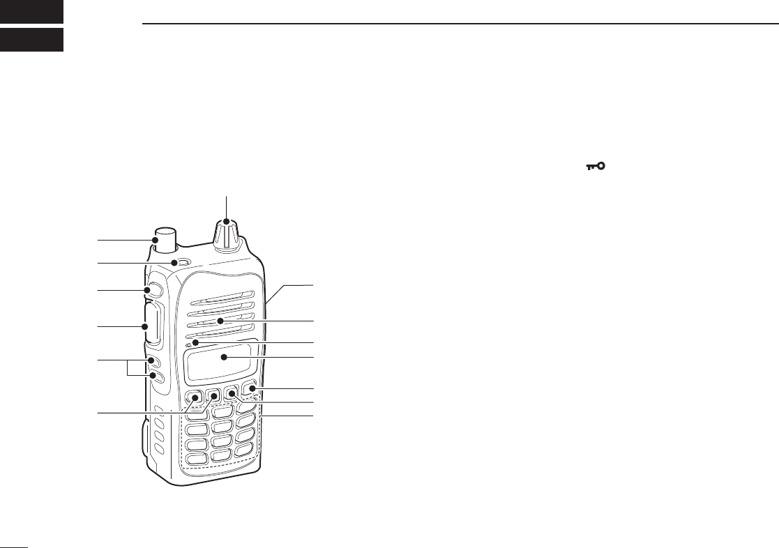
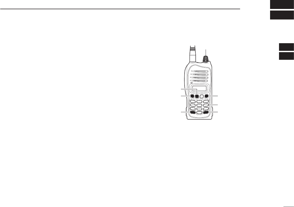
Panel description ■
q ANTENNA CONNECTOR [ANT] (p. 6)
Connects to the supplied antenna.
w KEY LOCK SWITCH [ ] (p. 9)
Push to turn ON the key lock function. ➥
Hold down for 2 seconds to turn OFF the key lock func- ➥
tion.
e LIGHT SWITCH [LIGHT]
Push to toggle the LCD backlight ON or OFF. (p. 11)
For the IC-A14S only
In the memory mode, hold down for 2 seconds to turn the
“TAG” setting ON or OFF. (p. 20)
r PTT SWITCH [PTT]
Hold down to transmit; release to receive.
t SQUELCH UP/DOWN KEYS [SQLY]/ [SQLZ] (p. 9)
Push either key to select the squelch level.
• 10 squelch levels, 1–10, and squelch open, 0, are selectable.
y UP/DOWN KEYS [Y]/[Z]
Push to change or select the operating frequency, ➥
memory channel, Set mode setting, and so on. (p. 8)
While scanning, push to change the scanning direction. ➥
(pp. 18, 19)
For the IC-A14S only
Hold down for 1 second to start scanning. (pp. 18, 19)
1
1PANEL DESCRIPTION
q
w
r
e!0
Function
display (p. 5)
o
i
u
Microphone
Speaker
!1
t
y
2
u KEYPAD (Available with only the IC-A14; pp. 3, 4)
i MEMORY MODE/MEMORY WRITE KEY [MR]/[MW]
Push to select the memory mode. (p. 12)
For the IC-A14
Push ➥[FUNC] then push this key to enter the select
memory write mode. (p. 13)
In the memory mode, push ➥[FUNC] then push this key
to copy the memory content to the frequency mode.
(p. 16)
For the IC-A14S
Hold down for 1 second to enter the select memory ➥
write mode. (p. 14)
In the memory mode, hold down for 1 second to copy ➥
the memory content to the frequency mode. (p. 16)
o CLEAR/HOME SWITCH [CLR]/[HOME]
Push to select the frequency mode. (p. 8) ➥
Hold down for 2 seconds to reset the transceiver to the ➥
user-default state without changing the memory con-
tents (home function). (p. 21)
!0 EXTERNAL SPEAKER AND MICROPHONE JACKS
[MIC/SP] (p. 39)
If desired, connects the optional speaker microphone or a
headset using the optional OPC-499 HEADSET ADAPTER.
NEVER connect an optional speaker-microphone,
headset adapter, while the transceiver power is ON.
!1 VOLUME CONTROL KNOB [VOL]
Rotate to turn the transceiver power ON or OFF and ad-
just the audio level.
1
PANEL DESCRIPTION
Jack cover
NOTE: Attach the jack
cover when optional
equipment is not used.
1
2
3
4
5
6
7
8
9
10
11
12
13
14
15
16
17
18
19

3
1PANEL DESCRIPTION
D KEYPAD (Available with IC-A14 only)
➥
Inputs digit “1” for frequency input or memory chan-
nel selection. (pp. 8, 12)
➥
Inputs “1,” “Q,” or “Z” when programming memory
names.
(p. 15)
After pushing ➥[FUNC], turns the ANL (Automatic
Noise Limiter) function ON or OFF. (p. 22)
➥
Inputs digit “2” for frequency input or memory chan-
nel selection. (pp. 8, 12)
➥
Inputs “2,” “A,” “B,” or “C” when programming
memory names.
(p. 15)
After pushing ➥[FUNC], starts the scan. (pp. 18,
19)
➥
Inputs digit “3” for frequency input or memory chan-
nel selection. (pp. 8, 12)
Inputs “3,” “D,” “E,” or “F” when programming ➥
memory names. (p. 15)
After pushing ➥[FUNC], selects memory bank
mode, during memory mode. (p. 12)
➥
Inputs digit “4” for frequency input or memory chan-
nel selection. (pp. 8, 12)
➥
Inputs “4,” “G,” “H,” or “I” when programming mem-
ory names.
(p. 15)
After pushing ➥[FUNC], turns the weather alert
function ON or OFF. (p. 23)
➥
Inputs digit “5” for frequency input or memory chan-
nel selection. (pp. 8, 12)
➥
Inputs “5,” “J,” “K,” or “L” when programming mem-
ory names.
(p. 15)
After pushing ➥[FUNC], enters duplex transmit fre-
quency programming condition, during NAVI band
operation. (p. 24)
➥
Inputs digit “6” for frequency input or memory chan-
nel selection. (pp. 8, 12)
➥
Inputs “6,” “M,” “N,” or “O” when programming
memory names.
(p. 15)
After pushing ➥[FUNC], selects duplex operation
during NAVI band operation. (p. 24)
➥
Inputs digit “7” for frequency input or memory chan-
nel selection. (pp. 8, 12)
➥
Inputs “7,” “P,” “R,” or “S” when programming
memory names.
(p. 15)
After pushing ➥[FUNC], selects weather channel
mode. (p. 23)
➥
Inputs digit “8” for frequency input or memory chan-
nel selection. (pp. 8, 12)
➥
Inputs “8,” “T,” “U,” or “V” when programming mem-
ory names.
(p. 15)
After pushing ➥[FUNC], key touch beep output ON
or OFF. (p. 22)

4
1
PANEL DESCRIPTION
➥
Inputs digit “9” for frequency input or memory chan-
nel selection. (pp. 8, 12)
➥
Inputs “9,” “W,” “X,” or “Y” when programming
memory names.
(p. 15)
After pushing ➥[FUNC], toggles scan tag setting
ON or OFF. (p. 20)
➥
Inputs digit “0” for frequency input or memory chan-
nel selection. (pp. 8, 12)
➥
Inputs “0,” “space” or “–” when programming mem-
ory names. (p. 15)
After pushing ➥[FUNC], selects the emergency fre-
quency, 121.500 MHz. (p. 21)
Sets the numeral input for frequency or memory ➥
channel numbers. Enters consecutive zero into
the remaining digits.
(pp. 8, 12)
After pushing ➥[FUNC], hold down for 1 second to
entering into set mode.
(p. 25)
Push to activate the function, then push another ➥
key to access its secondary function. When the
function is activated, the “F” icon appears.
1
2
3
4
5
6
7
8
9
10
11
12
13
14
15
16
17
18
19

5
1PANEL DESCRIPTION
Function display ■
q FUNCTION ICON
Appears when [FUNC] is pushed.
w MEMORY ICON (p. 12)
Appears when memory channel mode is selected.
e TAG ICON (p. 20)
Appears when the selected memory channel is set as a
TAG channel.
r RX ICON (p. 10)
Appears when receiving a signal, or when the squelch is
open.
t TX ICON (p. 10)
Appears while transmitting.
y DUPLEX ICON (IC-A14 only) (p. 24)
Appears when the duplex function is activate. ➥
Blinks while setting the duplex frequency. ➥
u ANL ICON (p. 22)
Appears when the ANL (Automatic Noise Limiter) func-
tion is in use.
i WEATHER ALERT ICON (IC-A14 only) (p. 23)
Appears when the weather alert function is in use.
o LOCK ICON (p. 9)
Appears when the lock function is in use.
!0 LOW BATTERY ICON (p. 11)
Appears when the battery is nearing exhaustion. The ➥
attached battery pack requires recharging when this
icon appears.
Blinks when battery recharging/replacing is immedi- ➥
ately needed.
!1 FREQUENCY READOUT
Displays the operating frequency, memory channel num-
ber, memory name or the Set mode item, and so on, de-
pending on the selected mode.
qwe r t yuio
!
1
!0
6
2
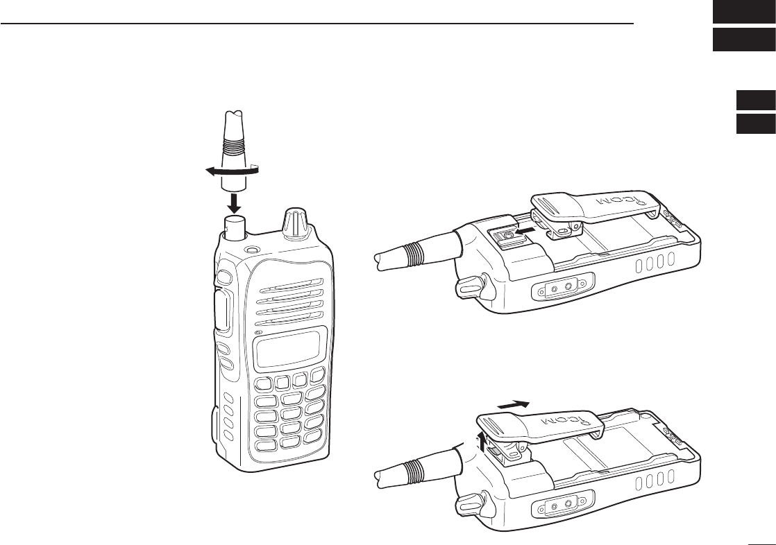
ACCESSORY ATTACHMENT
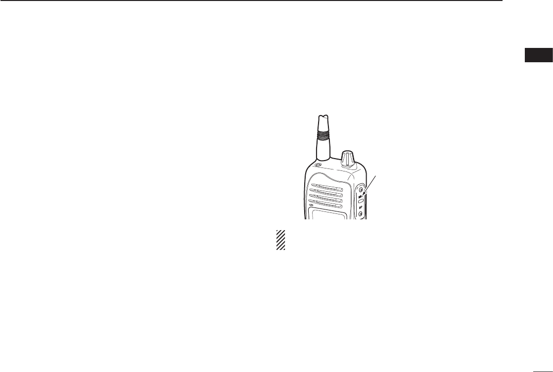
D Antenna
Insert the supplied antenna into the
antenna connector and screw down
the antenna as shown at right.
CAUTION!
• NEVER carry the transceiver by
holding only the antenna.
• DO NOT transmit without an
antenna. Otherwise the transceiv-
er may be damaged.
D Belt clip
Conveniently attaches to your belt.
- To attach the belt clip
q Remove the battery pack if it is attached.
w Slide the belt clip in the direction of the arrow until the belt
clip is locked and makes a ‘click’ sound.
- To detaching the belt clip
q Remove the battery pack if it is attached.
w Pinch the clip (q), and slide the belt clip in the direction of
the arrow (w).
q
w
1
2
3
4
5
6
7
8
9
10
11
12
13
14
15
16
17
18
19
7
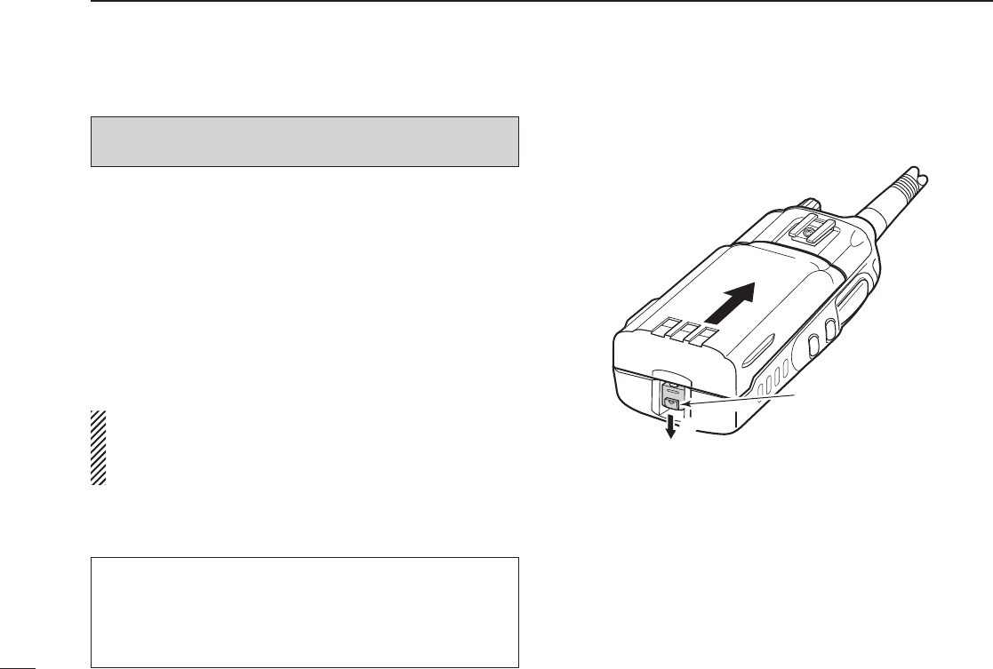
D Battery pack attachment
To attach the battery pack:
Slide the battery pack in the direction of the arrow (q), then
lock it with the battery release button.
• Slide the battery pack until the battery release button makes a
‘click’ sound.
To detach the battery pack:
Slide the battery release button in the direction of the arrow
(w) as shown in the illustration at right. The battery pack can
then be detached.
NEVER release or attach the battery pack when the trans-
ceiver is wet or soiled. This may result water or dust get-
ting into the transceiver/battery pack and may result in the
transceiver being damaged.
2ACCESSORY ATTACHMENT
q
w
Battery release button
Turn OFF the transceiver power by rotating [VOL] before at-
taching or detaching the battery pack.
For your information
If the transceiver power cannot be turned ON after replac-
ing the fully charged battery pack, do as follow.
Detach the battery pack, wait for approximately 10 seconds,
then attach the battery pack and turn ON the power again.
8
3
BASIC OPERATION
Setting a frequency ■
D Using the [Y]/[Z] keys
q Rotate [VOL] to turn ON power, then push [CLR] to select
the frequency mode if a memory CH number or WX CH
number appears on the function display.
w Push [Y]/[Z] to set the desired frequency.
- For the IC-A14 only -
• 1 MHz tuning step is selectable. Push [FUNC], then
push [Y]/[Z]. Push [FUNC] again to return to normal
tuning.
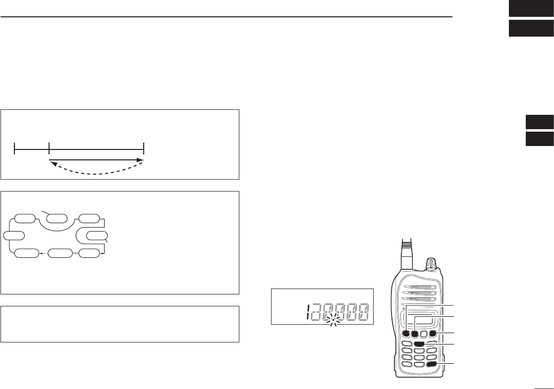
D Using keypad (IC-A14 only)
q Rotate [VOL] to turn ON power, then push [CLR] to select
the frequency mode if a memory CH number or WX CH
number appears on the function display.
w Push 5 appropriate digit keys to input the frequency.
• Push [1] as the 1st digit.
• When a wrong digit is input, push [CLR] to clear, then repeat
step w again.
• Push [ENT] to enter consecutive zero digits.
• Only [2], [5], [7] or [0] can be entered as the 5th and fi nal digit.
[EXAMPLE]
• 111.225 MHz: Push [1], [1], [1], [2], [2]
• 117.250 MHz: Push [1], [1], [7], [2], [5]
• 120.000 MHz: Push [1], [2], [ENT]
• 125.300 MHz: Push [1], [2], [5], [3], [ENT]
2
3
[VOL]
[FUNC]
[Z]
[ENT]
[CLR]
[Y]
Keypad
1
4
5
6
7
8
9
10
11
12
13
14
15
16
17
18
19
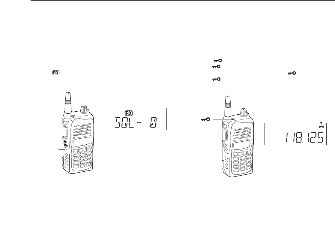
Setting a squelch level ■
The transceiver has a noise squelch circuit to mute undesired
noise while no signal is received.
q Push [SQLY] or [SQLZ] to select the squelch level.
• ‘SQL--0’ is open squelch and ‘SQL--10’ is tight squelch.
• The “ ” icon appears while the squelch is open.
w
Wait for 1 second to return to the previous display.
Lock function ■
The lock function prevents accidental frequency changes or
accidental function activation.
q Push [ ] to turn the lock function ON.
• The “ ” icon appears.
w To turn the function OFF, hold down [ ] for 2 seconds.
• The “ ” icon disappears.
9
3BASIC OPERATION
[SQLY]
“SQL-- 0”; Squelch open
[SQLZ]
[ ]
Appears while the key lock
function is activated.
10
3
BASIC OPERATION
3
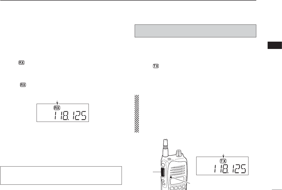
Receiving ■
q Rotate [VOL] to turn ON the power.
w Push [SQLZ] several times to open the squelch.
• Select the squelch level 0.
e Rotate [VOL] to adjust the audio level.
r Push [SQLY] several times until the noise is muted.
• The “ ” icon disappears.
t Set the desired frequency using [Y]/[Z] keys or the key-
pad keys.
y When a signal is received on the set frequency:
• The “ ” icon appears.
• Squelch opens and audio is emitted from the speaker.
When the squelch setting is too “tight” (large number setting),
squelch may not open for weak signals. To receive weaker
signals, loosen (small number setting) the squelch.
Transmitting ■
q Set the desired frequency in COM band pushing [Y]/[Z]
or the keypad keys (IC-A14 only).
• COM band frequency range: 118.00–136.975 MHz
w Hold down [PTT] to transmit.
• The “ ” icon appears.
e Speak into the microphone at a normal voice level.
• DO NOT hold the transceiver too close to your mouth or speak
too loudly. This may distort the signal.
r Release [PTT] to receive.
NOTE: About Time-Out-Timer function
To prevent prolonged transmission, according to regula-
tory requirements, the IC-A14/S has a Time-Out Timer
function. This timer cuts OFF transmission after the set
time period of continuous transmission.
The Time-Out Timer is set in the Set mode. See page 26
for details.
CAUTION: Transmitting without an antenna may damage
the transceiver.
NOTE: To prevent interference, listen on the frequency
before transmitting. If the frequency is busy, wait until it is
clear.
[PTT]
Microphone
Appears while transmitting
Appears when a signal is received.
1
2
4
5
6
7
8
9
10
11
12
13
14
15
16
17
18
19
11
3BASIC OPERATION
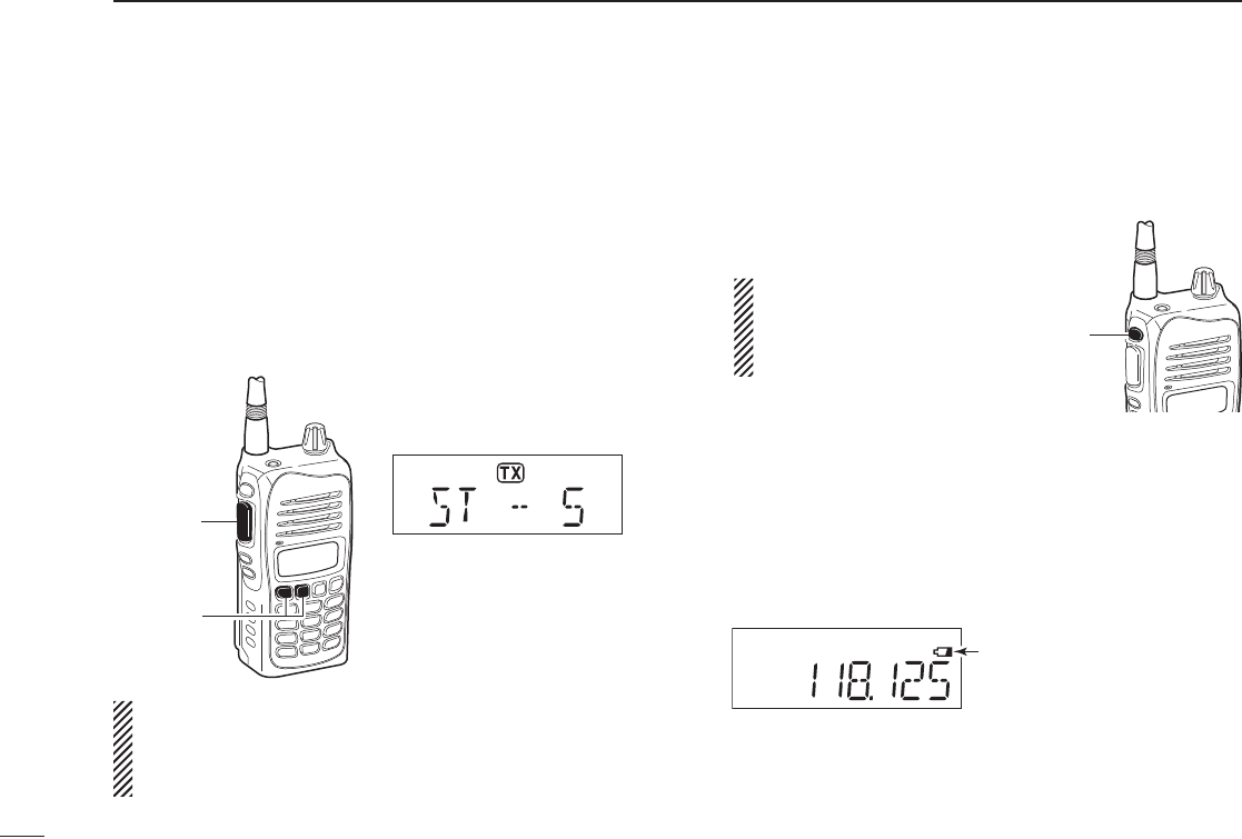
Side tone function ■
When using a headset (other manufacture’s products), the trans-
ceiver outputs your transmitted voice to the headset for mon-
itoring. Connect an optional headset to use this function (The
OPC-499 HEADSET ADAPTER and headset are required). (p. 39)
D Setting the side tone level
q Push [PTT] to turn the transmit mode ON.
w While transmitting, push [Y]/[Z] to adjust the level.
• ‘ST--0’ is OFF and ‘ST--10’ is the maximum level.
WARNING! NEVER operate the transceiver with a head-
set at high volume or monitor levels for a long periods
time. A ringing in your ears may occur. If so, reduce the
volume or monitor level, or discontinue use.
LCD backlight ■
The IC-A14/S has an LCD backlight for convenience during
night time operation.
Push ➥[LIGHT] to turn the LCD
backlight ON or OFF.
IMPORTANT!
Turn OFF the LCD back-
light when no backlight is
necessary.
Low battery icon ■
The low battery icon appears or blinks when the battery
power has decreased to a specifi ed level. The attached bat-
tery pack or battery case requires recharging or the battery
case cells need replacing.
If the batteries are not charging or replaced, even when the
low battery indicator blinks, a long beep sounds and then the
transceiver will automatically be turned OFF.
[PTT]
[Z]/[Y]
Side tone level is indicated
IMPORTANT!
Select ‘ST--0’ when a speaker
microphone is connected, oth-
erwise your voice will be heard
from the speaker during trans-
mit.
[LIGHT]
Appears when the battery
is nearly exhausted.
Blinks when the battery
recharging or replacing is
immediately necessary.
12
4
MEMORY OPERATION
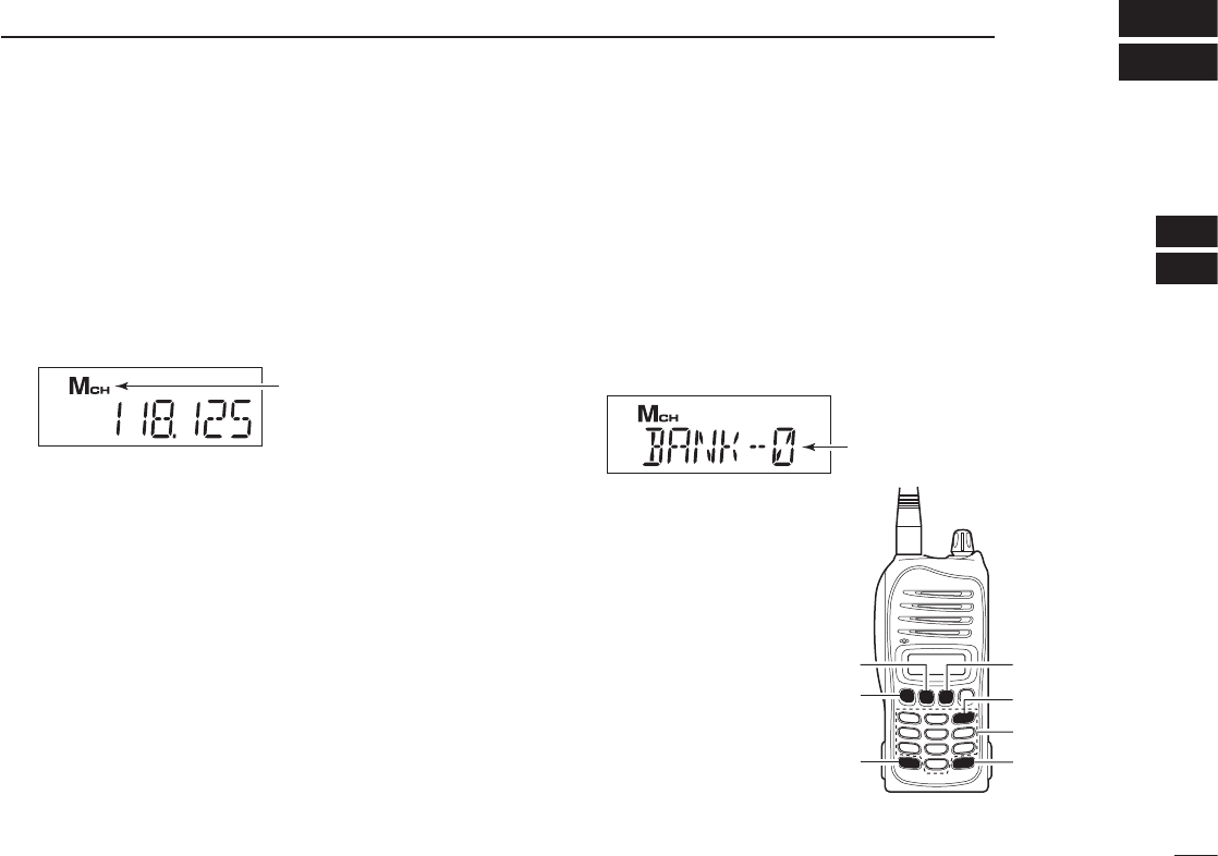
Memory channel selection ■
The IC-A14 has 200 memory channels (20 channels in 10
banks; default setting) and the IC-A14S has 100 memory chan-
nels for storing often-used frequencies.
q Push [MR] to select the memory mode.
• The memory mode icon appears and a memory channel num-
ber is briefl y displayed .
• The memory bank number is also displayed on the IC-A14.
Using [Y]/[Z]:
w Push [Y]/[Z] to select the desired memory CH number.
• The memory channel number is briefl y displayed, then the pro-
grammed frequency (or memory name, if programmed) is dis-
played.
• If no memory channel is programmed, no memory channel can
be selected.
Using the Keypad— IC-A14 only:
w Push 2 appropriate digit key (00 to 99, depending on the
bank setting) to select the desired memory channel num-
ber, then push [ENT].
• The memory channel number is briefl y displayed, then the pro-
grammed frequency (or memory name, if programmed) is dis-
played.
• If no memory channel is programmed in the selected BANK, no
memory channel can be selected.
Memory bank selection ■
(Available with the IC-A14 only)
A total of 200 memory channels in the IC-A14, are divided
into bank (up to 10 banks are selectable, depending on the
setting) for simple memory grouping.
q Push [MR] to select the memory mode.
w Push [FUNC], and push [BANK](3) to enter the bank se-
lection mode.
e Push [Y]/[Z] or an
appropriate digit key
([0] to [9]) to select
the desired memory
BANK number, then
push [ENT].
r Push [Y]/[Z], or
2 appropriate digit
keys and then [ENT]
to select the desired
memory channel.
Appears when the
memory mode is selected.
Appears when the bank
selection mode is selected.
Keypad
[FUNC]
[Z]
[ENT]
[BANK](3)
[MR]
[Y]
1
2
3
4
5
6
7
8
9
10
11
12
13
14
15
16
17
18
19
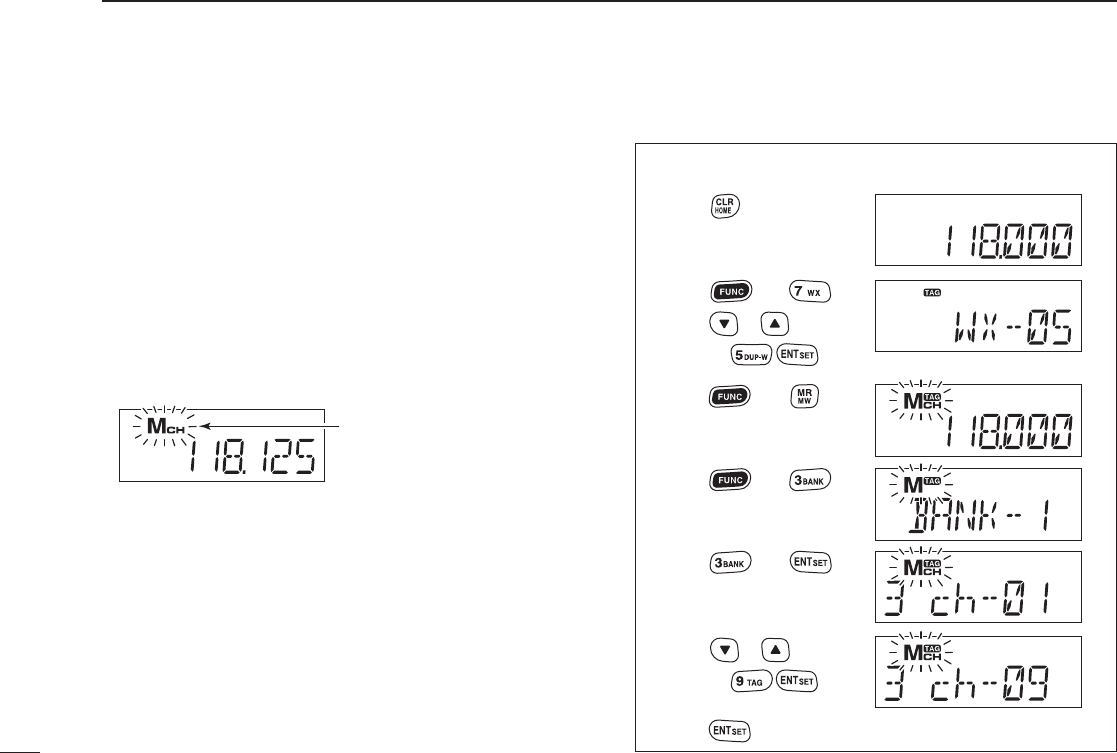
Programming a memory channel ■
Program often-used frequencies using the following instruc-
tions.
D For the IC-A14
q Push [CLR] to select the frequency mode, if necessary.
w Set the desired frequency. (p. 8)
• Push [FUNC], then push [WX](7) to select a weather channel
mode, and then select the desired weather channel using [Y]/
[Z] or keypad if desired. (p. 23)
e Push [FUNC] then push [MW](MR) to enter the select
memory write mode.
• The memory mode icon blinks.
r Push [Y]/[Z] to select a desired memory channel num-
ber.
• Push [FUNC], then push [BANK](3) to enter the bank selection
mode, and push [Y]/[Z] or an appropriate digit keys ([0]–[9]),
then push [ENT] to select the BANK number, if desired.
t Push [ENT] to program the entry and return to the fre-
quency mode.
13
4MEMORY OPERATION
• EXAMPLE: Programming WX-05 into memory channel 9
in memory BANK 3.
Blinks when the select
memory write mode is
selected.
No frequency is displayed when a blank channel is
selected.
Push
Push then
Push then
Push then
Push or ,
or, push
Push or ,
or, push
Push then
*Briefly appears.
Push to complete the programming.
*Briefly appears.
14
4
MEMORY OPERATION
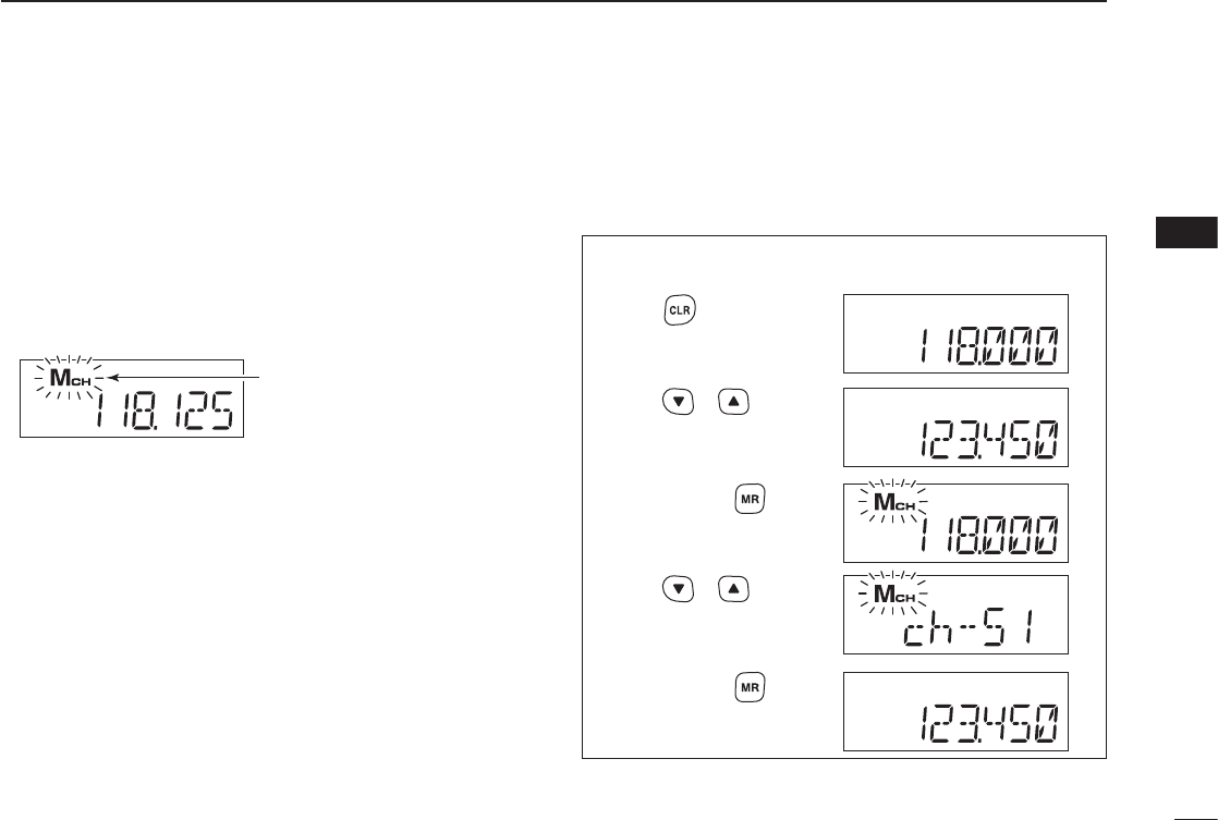
D For the IC-A14S
q Push [CLR] to select the frequency mode, if necessary.
w Set the desired frequency. (p. 8)
e Hold down [MR] for 1 second to enter the select memory
write mode.
• The memory mode icon blinks.
r Push [Y]/[Z] to select the desired memory channel num-
ber.
t Hold down [MR] for 1 second to set the entry and return
to the frequency mode.
Blinks when the select
memory write mode is
selected.
No frequency is displayed when a blank channel is
selected.
• EXAMPLE: Programming 123.450 MHz into memory
channel 51.
Push or
Push or
*Briefly appears.
Push and hold
for 1 second.
Push and hold
for 1 second.
Push
1
2
3
4
5
6
7
8
9
10
11
12
13
14
15
16
17
18
19

15
4MEMORY OPERATION
Memory names ■
The memory channel can display an 8-character name in-
stead of the programmed frequency.
D Programming memory names
q Set the desired frequency in the frequency mode. (p. 8)
w Enter the select memory write mode.
• For the IC-A14; push [FUNC] then push [MW](MR).
• For the IC-A14S; hold down [MR] for 1 second.
e Select the desired memory channel to be programmed by
pushing [Y]/[Z] (or on only the IC-A14, push the keys on the
keypad then [ENT]).
r Push [MR] momentarily to enter the memory name pro-
gramming mode.
• “-- -- -- -- -- -- -- --” appears and 1st digits blink.
• Available characters
For the IC-A14
t Push the appropriate digit key several times to select the
desired character, as shown to the left.
• To move the cursor forwards or backwards, use [Y]/[Z].
• The cursor automatically moves forward when a different key is
pushed.
• To erase a character, overwrite with a space (displayed as
“_”).
y Push [ENT] to program the name and frequency at the
same time.
• Return to the frequency display.
• If no name is programmed, the programmed frequency is dis-
played.
• To clear the entered memory names, push [CLR] before push-
ing [ENT].
For the IC-A14S
t
Push [Y]/[Z] several times to select the desired character.
• To move the cursor forwards, use [MR].
• To erase a character, overwrite with a space (displayed as
“_”).
y Hold down [MR] for 1 second to program the name and
frequency at the same time.
• Return to the frequency display.
• If no name is programmed, the programmed frequency is dis-
played.
• To clear the entered memory names, push [CLR] before hold-
ing down [MR] for 1 second.
KEY CHARACTER KEY CHARACTER
[1] 1, Q, Z [6] 6, M, N, O,
[2] 2, A, B, C [7] 7, P, R, S
[3] 3, D, E, F [8] 8, T, U, V
[4] 4, G, H, I [9] 9, W, X, Y
[5] 5, J, K, L [0] 0, _ (space), –

16
4
MEMORY OPERATION
NOTE: When programming a memory name to the pro-
grammed memory channel, operate as follow.
q Select the desired memory channel that requires a name.
(see p. 12).
For the IC-A14
w Push [FUNC] then push [MW](MR).
• The selected memory contents copied into frequency mode and
frequency mode is selected automatically.
e Push [FUNC] then push [MW](MR) again.
r Push [MR] momentarily to select memory name program-
ming mode.
t Perform the steps t and y described at left page in “For
the IC-A14” to program the desired memory name.
For the IC-A14S
w Hold down [MR] for 1 second.
• The selected memory contents copied into frequency mode and
frequency mode is selected automatically.
e Hold down [MR] for 1 second again.
r Push [MR] momentarily to select memory name program-
ming mode.
t Perform the steps t and y described at left page in “For
the IC-A14S” to program the desired memory name.
Copying memory contents ■
This function copies a memory channel’s contents into the
frequency mode. This is useful when searching for signals
around a memory channel’s frequency.
q Push [MR] to select the memory mode.
w Select the desired memory channel to be copied using
[Y]/[Z] (or keypad and [ENT]; For the IC-A14 only).
• Select the desired bank if desired.
For the IC-A14
e Push [FUNC], then push [MW](MR) to copy the memory
channel’s contents into the frequency mode.
• Frequency mode is automatically selected.
For the IC-A14S
e Hold down [MR] for 1 second to copy the memory chan-
nel’s contents into the frequency mode.
• Frequency mode is automatically selected.
1
2
3
4
5
6
7
8
9
10
11
12
13
14
15
16
17
18
19

17
4MEMORY OPERATION
■
Clearing the memory contents
(Available with the IC-A14 only)
Unwanted memory channels can be cleared.
q Select the desired memory channel to be cleared. (p. 12)
• Select the desired bank if desired. (p. 12)
w Push [FUNC] then hold down [CLR] for 1 second.
• “-- -- -- -- -- -- ” appears briefl y, then the next selectable channel
appears.
18
5
SCAN OPERATION
Scan types ■
The IC-A14 has 3 scan types to suit your needs. IC-A14S
has 2 scan types.
COM band scan ■
q Push [CLR] to select the frequency mode.
w Push [SQLY]/[SQLZ] to set the squelch level to the point
where noise is just muted.
For the IC-A14
e Push [FUNC], then push [SCAN](2) to start the scan.
• When a signal is received, the scan pauses until it disappears.
• To change the scanning direction, push [Y]/[Z].
For the IC-A14S
e Hold down [Y]/[Z] for 1 second to start the scan.
• When a signal is received, the scan pauses until it disappears.
• To change the scanning direction, push [Y]/[Z].
r To stop the scan, push [CLR].
WEATHER CHANNEL SCAN
Repeatedly scans all “TAG” weather channels. Weather
channels are available for the IC-A14 only.
COM BAND SCAN
Repeatedly scans
all frequencies
over the entire
COM band.
108.00
MHz
Scan
Jump
118.00
MHz
136.975
MHz
MEMORY SCAN
Repeatedly scans se-
lected memory bank’s
all “TAG” memory chan-
nels. Used for checking
often-used channels and
bypassing usually busy
channels such as control-
tower frequencies.
non-TAG
channel
non-TAG channel
Mch 2 Mch 4 Mch 6
Mch 7Mch 1
Mch 8Mch 10Mch 19
Decimal point blinks during
scan.
[FUNC]
[CLR]
[SCAN](2)
[Y]
[Z]
1
2
3
4
5
6
7
8
9
10
11
12
13
14
15
16
17
18
19
Weather channel scan ■
(Available with the IC-A14 only)
q Push [FUNC], then push [WX](7) to select a weather
channel mode.
w Set squelch to the point where noise is just muted with
[SQLY]/[SQLZ].
e Push [FUNC], then push [SACN(2) to start the scan.
• When a signal is received, the scan pauses until it disappears.
• To change the scanning direction, push [Y]/[Z].
r To stop the scan, push [CLR].
Memory scan ■
NOTE: Program 2 or more memory channels with “TAG”
setting to start memory scan.
q Push [MR] to select the memory mode.
• For the IC-A14, select the desired BANK if desired. (p. 12)
w Push [SQLY]/[SQLZ] to set the squelch level to the point
where noise is just muted.
For the IC-A14
e Push [FUNC], then push [SCAN](2) to start the scan.
• When a signal is received, the scan pauses until it disappears.
• To change the scanning direction, push [Y]/[Z].
For the IC-A14S
e Hold down [Y]/[Z] for 1 second to start the scan.
• When a signal is received, the scan pauses until it disappears.
• To change the scanning direction, push [Y]/[Z].
19
5SCAN OPERATION
Decimal point blinks during
scan.
[FUNC]
[SCAN](2)
[WX](7)
[Y]
[Z]
Decimal point blinks during
scan.
[FUNC]
[MR]
[SCAN](2)
[Y]
[Z]
r To stop the scan, push
[CLR].

20
5
SCAN OPERATION
5
“TAG” channel setting ■
Memory and weather channels* can be specified to be
skipped for the memory and weather channel* scans respec-
tively. The “TAG” channel function is only selectable in the
scan mode. *For the IC-A14 only
For the IC-A14
q Push [MR] to select the memory mode; or, push [FUNC],
then push [WX](7) to select a weather channel.
• Select the desired BANK, if desired.
w Select the desired memory/weather channel to be a “TAG”
channel.
• Select the desired BANK, if desired.
e Push [FUNC], then push [TAG](9) to set a “TAG.”
• “TAG” appears.
• Non-“TAG” channels are skipped during scan.
r To cancel the “TAG” setting, repeat above steps.
For the IC-A14S
q Push [MR] to select the memory mode.
w Select the desired memory channel to be a “TAG” chan-
nel.
e Hold down [LIGHT] for 2 seconds to set a “TAG.”
r To cancel the “TAG” setting, repeat the above steps.
No “ ” icon appears with
the skipped channel.
The “ ” icon appears with
the scanned channel.
1
2
3
4
6
7
8
9
10
11
12
13
14
15
16
17
18
19
21
6OTHER FUNCTIONS
Home function ■
The home function is convenient if you want to return the
transceiver to default settings without memory channels.
The following transceiver’s settings will return to the default
value;
• Operating mode (Frequency, memory or weather* channel mode
with frequency or channel number, including bank*)
• Duplex setting • ANL setting • Key touch beep
• Squelch level • Side tone level • Microphone gain
• Internal microphone usage • Time-Out timer setting
The default settings can be modifi ed to suits your preference
using with the optional cloning software, CS-A14.
¬ Hold down [CLR] for 2 seconds
to return the transceiver into the
default setting.
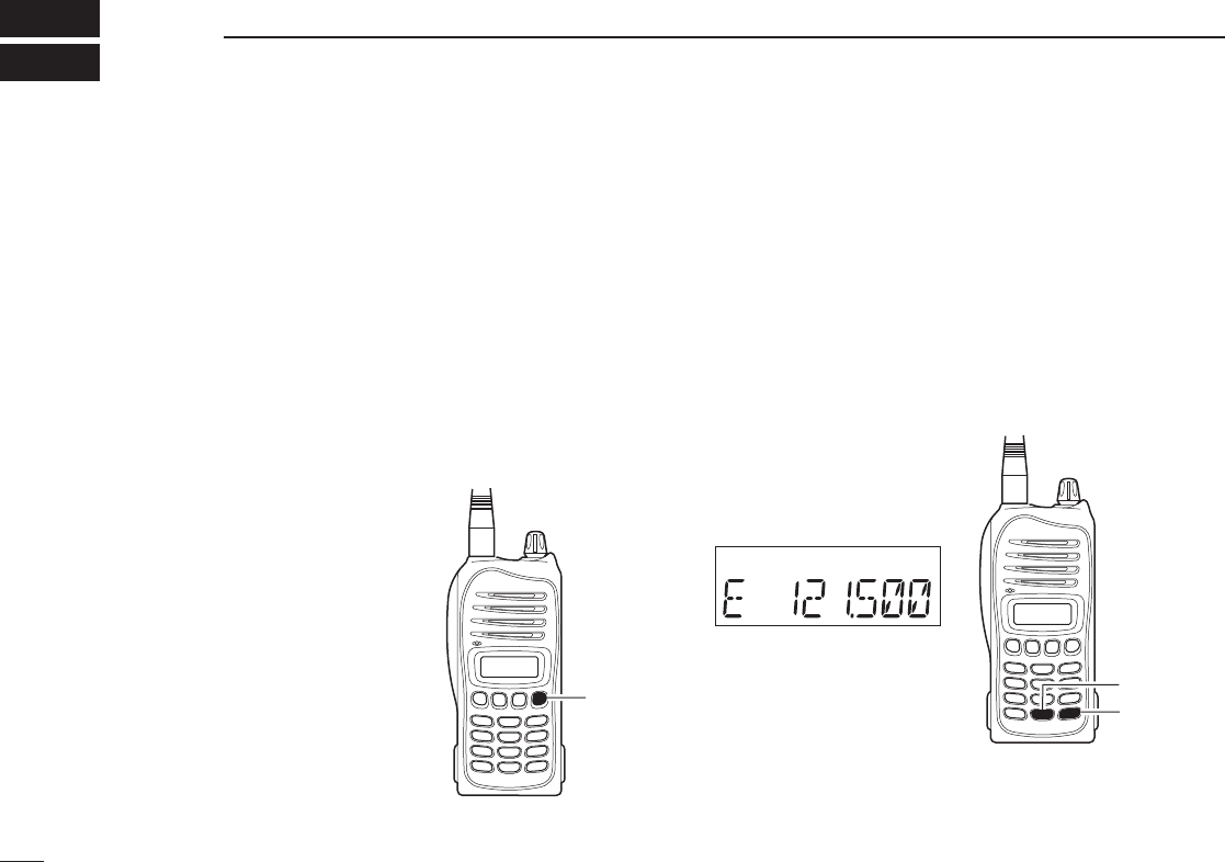
Accessing 121.5 MHz emer- ■
gency frequency
(Selectable on only the IC-A14)
The IC-A14 can quickly be set to the 121.5 MHz emergency
frequency. This function can be activated even when the key
lock function is in use.
q Push [FUNC] then [121.5](0) to call the emergency fre-
quency.
w Push [CLR] to return to the frequency mode.
[CLR]
Emergency initial, “E,” ap-
pears with the frequency
[FUNC]
[121.5](0)
*For only the IC-A14

22
6
OTHER FUNCTIONS
Key touch beep tone ■
The beep tone, which sounds at the push of a switch can be
set, if desired.
For the IC-A14
Push ➥[FUNC] then push [BEEP](8) to turn the key touch
beep tone ON or OFF.
• Key touch beep setting is displayed briefly.
For the IC-A14S
q Rotate [VOL] to turn the transceiver power OFF.
w While holding down [Y]/[Z], rotate [VOL] to enter set
mode.
e Push [MR] several times to select the key touch beep
item, “BEEP.”
r Push [Y]/[Z] to select either ON or OFF.
t Push [CLR] to return to frequency mode.
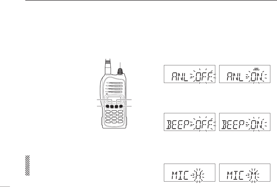
ANL function ■
The ANL (Automatic Noise Limiter) function reduces noise
components such as that caused by engine ignition systems
while receiving.
For the IC-A14
Push ➥[FUNC] then push [ANL](1) to turn the ANL func-
tion ON/OFF.
• The “ANL” icon appears when the ANL function is ON.
For the IC-A14S
q Rotate [VOL] to turn the transceiver power OFF.
w While holding down [Y]/[Z], rotate [VOL] to enter set
mode.
e Push [MR] several times to select the ANL item, “ANL.”
r Push [Y]/[Z] to select either ON or OFF.
• The “ANL” icon appears when the ANL function is ON.
t Push [CLR] to return to the frequency mode.
“ANL” indicator appears when the ANL
function is in use.
1
2
3
4
5
6
7
8
9
10
11
12
13
14
15
16
17
18
19
23
6OTHER FUNCTIONS
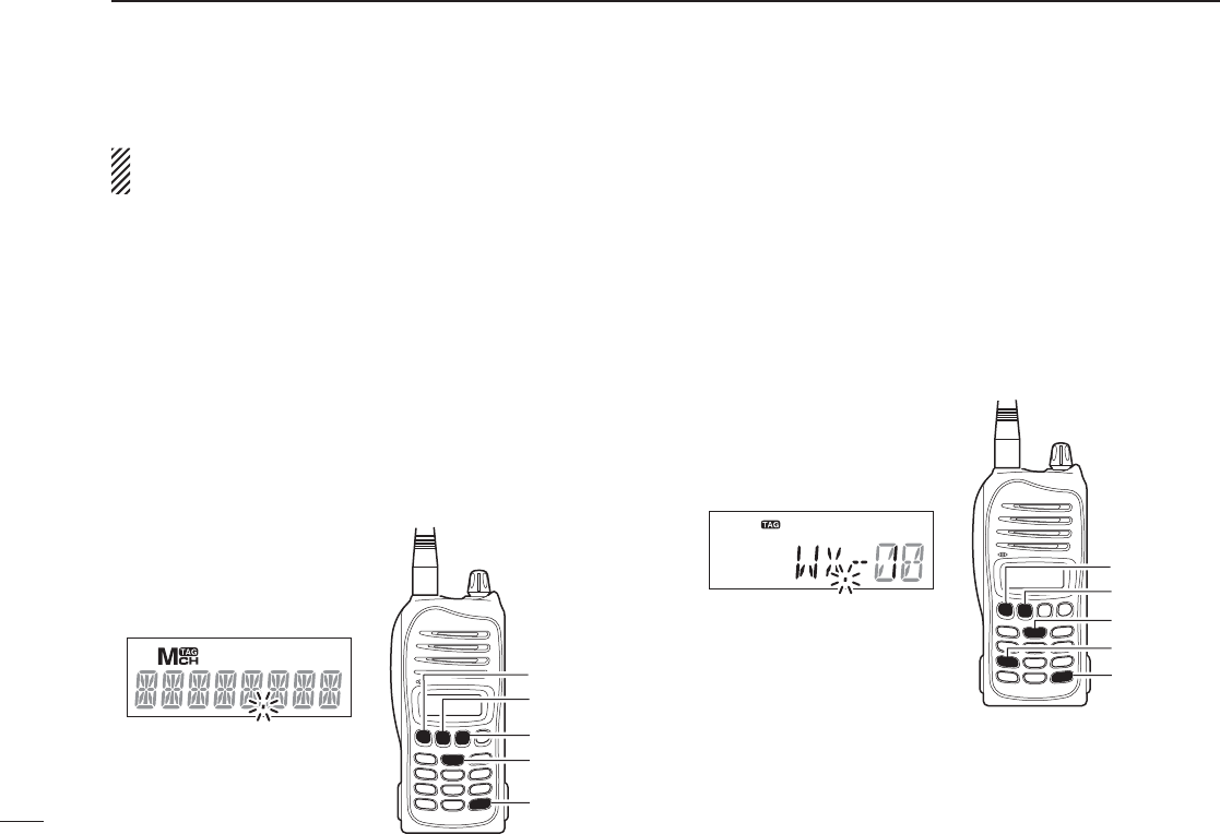
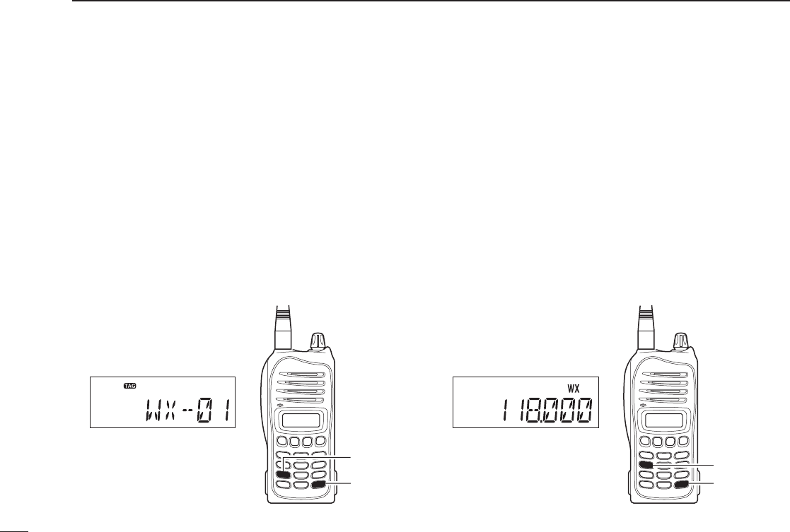
Weather channel operation ■
(Selectable on only the IC-A14)
The IC-A14 has VHF marine WX (weather) channel receiving
capability for fl ight planning.
D Weather channel selection
q Push [FUNC], then push [WX](7) to select WX channel
mode.
• “WX--” and previously selected channel number appears.
w Push [Y]/[Z] to select the desired WX channel.
e Push [CLR] to exit the WX channel mode and return to
the frequency mode.
D
Setting weather alert function
An NOAA broadcast station transmits a weather alert tone
before any important weather announcements. When the
weather alert function is turned ON, the transceiver detects
the alert, and sounds a beep tone until the transceiver is op-
erated. The previously selected (used) weather channel is
checked any time during standby, or while scanning.
¬
Push [FUNC], then push [WX-ALT](4) to turns the weather
alert function ON or OFF.
• The “WX” icon appears when the weather alert function ON.
Weather channel appears
[FUNC]
[WX](7)
The “WX” icon appears when
the weather alert is set to ON
[FUNC]
[WX-ALT](4)

Duplex operation ■(Selectable on only the IC-A14)
The duplex function allows you to call a fl ight service station
while receiving a VOR station. The duplex function requires
frequency programming for the fl ight service station in ad-
vance.
D Programming a duplex frequency
q Push [CLR] to select the frequency mode.
w Set a NAVI band frequency using [Y]/[Z] or keypad.
• NAVI band frequency range: 108.00–117.975 MHz
e Push [FUNC], then push [DUP-W](5).
• The “DUP” icon blinks and transmit frequency appears.
r Set the desired fl ight service station frequency using [Y]/
[Z] or keypad, then push [ENT].
• The displayed frequency returns to the NAVI band frequency.
D Operating the duplex function
q Set the desired frequency in NAVI band.
• NAVI band frequency range: 108.00–117.975 MHz
w Push [FUNC], then push [DUP](6) to turn the duplex func-
tion ON.
• The “DUP” icon appears.
e Hold down [PTT] to transmit on the pre-programmed
transmit frequency.
r Release [PTT] to return to receive.
t Push [FUNC], then push [DUP](6) to cancel the function.
• The “DUP” icon disappears.
NOTE: A duplex frequency can be programmed into each
memory channel independently. Set a duplex frequency
before programming the memory channel, if desired. The
duplex ON/OFF setting can also be programmed into a
memory channel.
24
6
OTHER FUNCTIONS
“DUP” indicator blinks during
transmit frequency setting
[FUNC]
[DUP](6)
[DUP-W](5)
“DUP” appears during duplex
operation
1
2
3
4
5
6
7
8
9
10
11
12
13
14
15
16
17
18
19
25
6OTHER FUNCTIONS
Set mode setting ■
The Set mode is used to program infrequently changed func-
tion items or options.
D Entering the set mode
q Rotate [VOL] to turn the
transceiver power OFF.
w While pushing and holding
[Y] and [Z], turn [VOL] to
enter the Set mode.
e Push [MR] several times
to select the desired Set
mode item.
r Push [Y]/ [Z] to select the
desired condition or value
for the item.
t Push [CLR] to return to fre-
quency mode.
For the IC-A14 only
Push [FUNC] then holding down [SET](ENT) for 1 second to
also enters into the Set mode.
For your information:
The default value of the Set mode items can be changed
with the optional CS-A14 cloning software. The default
settings are recalled by the home function.
D Set mode items
• ANL— ANL function (available with IC-A14S only)
Sets the ANL (Automatic Noise Limiter) function that reduces
noise components such as that caused by engine ignition
systems while receiving.
• BEEP— Key touch beep (available with IC-A14S only)
The beep tone which sounds at the push of a switch can be
set, if desired.
• MIC— Microphone gain
The internal microphone gain can be set to suit your needs.
“H” (High gain), “M” (Medium gain) and “L” (Low gain) can
be selected.
[VOL]
[MR]
[Z][CLR]
[Y]
26
6
OTHER FUNCTIONS
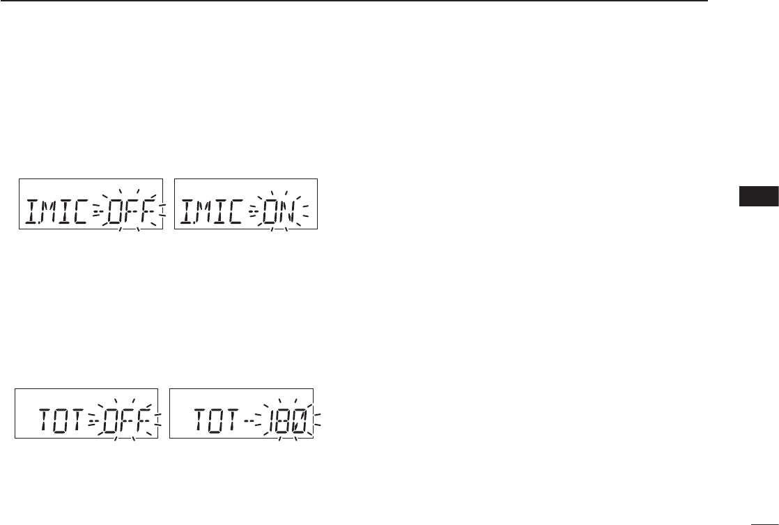
• I.MIC— Using the internal microphone
The internal microphone can be turned OFF to use a head-
set.
This setting prevents unwanted audio or noise entering the
internal microphone if the [PTT] is pushed.
• TOT— Time-out timer
Sets the time-out timer period to prevent prolonged transmis-
sions, according to regulatory requirements. This timer cuts
OFF a transmission after the set time period.
Set the timer to between 20 and 180 seconds (in 10 second
steps) or to OFF.
Ask your dealer for local regulation details.
1
2
3
4
5
6
7
8
9
10
11
12
13
14
15
16
17
18
19

27
7BATTERY PACKS AND CASE
Battery charging ■
RDANGER! Use and charge only specifi ed Icom battery
packs with Icom radios or Icom charger. Only Icom battery
packs are tested and approved for use and charge with Icom
radios or Icom charger. Using third-party or counterfeit bat-
tery packs or charger may cause smoke, fi re, or cause the
battery to burst.
D Battery caution
RDANGER! DO NOT hammer or otherwise impact the bat-
tery. Do not use the battery if it has been severely impacted
or dropped, or if the battery has been subjected to heavy
pressure. Battery damage may not be visible on the outside
of the case. Even if the surface of the battery does not show
cracks or any other damage, the cells inside the battery may
rupture or catch fi re.
RDANGER! NEVER use or leave battery packs in areas with
temperatures above +60°C. High temperature buildup in the
battery, such as could occur near fi res or stoves, inside a sun
heated car, or in direct sunlight may cause the battery to rup-
ture or catch fi re. Excessive temperatures may also degrade
battery performance or shorten battery life.
RDANGER! DO NOT expose the battery to rain, snow, sea-
water, or any other liquids. Never charge or use a wet bat-
tery. If the battery gets wet, be sure to wipe it dry before
using. The battery is not waterproof.
RDANGER! NEVER incinerate used battery packs since in-
ternal battery gas may cause them to rupture, or may cause
an explosion.
RDANGER! NEVER solder the battery terminals or NEVER
modify the battery pack. This may cause heat generation,
and the battery may rupture, emit smoke or catch fi re.
RDANGER! Use the battery only with the transceiver for
which it is specified. Never use a battery with any other
equipment, or for any purpose that is not specifi ed in this in-
struction manual.
RDANGER! If fl uid from inside the battery gets in your eyes,
blindness can result. Rinse your eyes with clean water, with-
out rubbing them, and see a doctor immediately.
RWARNING! Immediately stop using the battery if it emits
an abnormal odor, heats up, or is discolored or deformed. If
any of these conditions occur, contact your Icom dealer or
distributor.
RWARNING! Immediately wash, using clean water, any part
of the body that comes into contact with fl uid from inside the
battery.
Misuse of Lithium-ion batteries may result in the following
hazards: smoke, fi re, or the battery may rupture. Misuse
can also cause damage to the battery or degradation of
battery performance.

28
7
BATTERY PACKS AND CASE
7
RWARNING! NEVER put the battery in a microwave oven,
high-pressure container, or in an induction heating cooker.
This could cause a fi re, overheating, or cause the battery to
rupture.
CAUTION: Always use the battery within the specifi ed tem-
perature range for the transceiver (–10°C to +60°C; +14°F
to +140°F) and the battery itself (–20°C to +60°C; –4°F to
+140°F). Using the battery out of its specifi ed temperature
range will reduce the battery’s performance and battery life.
Please note that the specifi ed temperature range of the bat-
tery may exceed that of the transceiver. In such cases, the
transceiver may not work properly because it is out of its op-
erating temperature range.
CAUTION: Shorter battery life could occur if the battery is left
fully charged, completely discharged, or in an excessive tem-
perature environment (above +50°C) for an extended period
of time. If the battery must be left unused for a long time, it
must be detached from the radio after discharging. You may
use the battery until the remaining capacity is about half, then
keep it safely in a cool dry place with the temperature range
as below:
–20°C to +50°C; –4°F to +122°F (up to a month)
–20°C to +35°C; –4°F to +95°F (up to three months)
–20°C to +20°C; –4°F to +68°F (up to a year)
D Charging caution
RDANGER! NEVER charge the battery pack in areas with
extremely high temperatures, such as near fi res or stoves, in-
side a sun heated car, or in direct sunlight. In such environ-
ments, the safety/protection circuit in the battery will activate,
causing the battery to stop charging.
RWARNING! NEVER charge or leave the battery in the bat-
tery charger beyond the specifi ed time for charging. If the
battery is not completely charged by the specifi ed time, stop
charging and remove the battery from the battery charger.
Continuing to charge the battery beyond the specifi ed time
limit may cause a fi re, overheating, or the battery may rup-
ture.
RWARNING! NEVER insert the transceiver (battery attached
to the transceiver) into the charger if it is wet or soiled.
This could corrode the battery charger terminals or damage
the charger. The charger is not waterproof.
CAUTION: NEVER charge the battery outside of the spec-
ifi ed temperature range: BC-179 (0°C to +40°C; +32°F to
+104°F). Icom recommends charging the battery at +20°C
(+68°F). The battery may heat up or rupture if charged out of
the specifi ed temperature range. Additionally, battery perfor-
mance or battery life may be reduced.
1
2
3
4
5
6
8
9
10
11
12
13
14
15
16
17
18
19
29
7BATTERY PACKS AND CASE
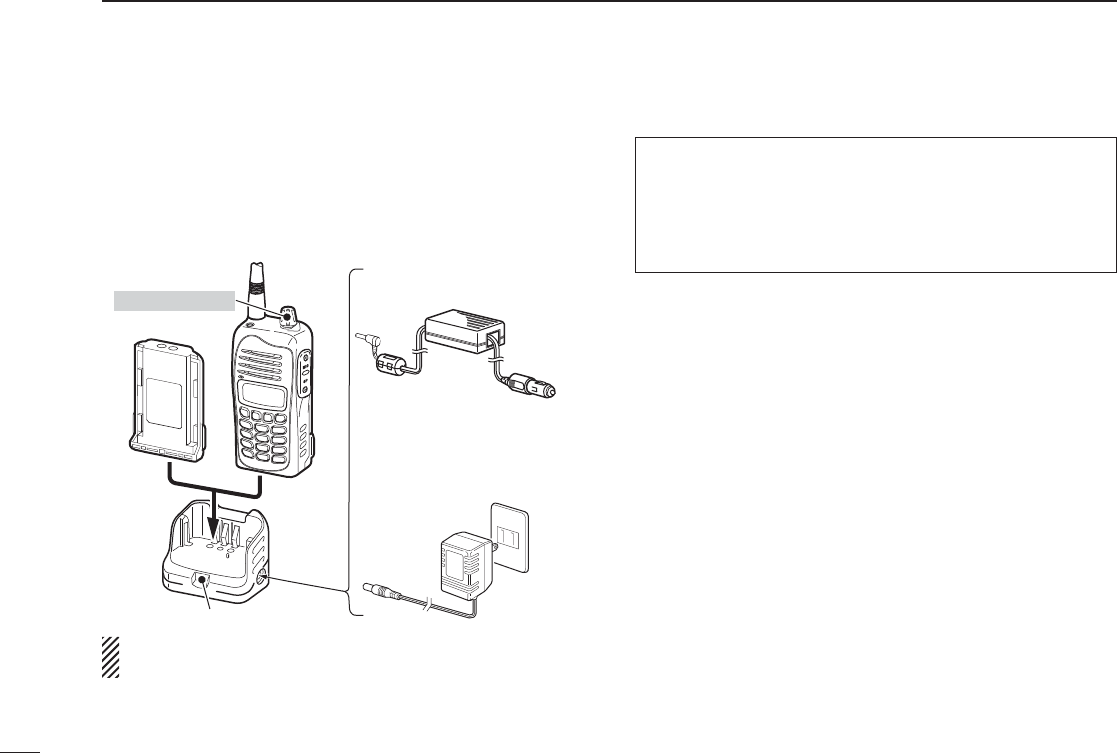
Charging the battery ■
D Regular charging with the BC-179+BC-174
The BC-179 provides regular charging of battery packs. The
following accessories are additionally required.
• An AC adapter (may be supplied, depending on the transceiver ver-
sions) or the optional cigarette lighter cable (CP-22).
Be sure to turn OFF the transceiver power, when charging
the battery pack with the transceiver.
• Charging period
Approximately 12 hours (with BP-232N)
Approximately 13.5 hours (with BP-232H)
• Charging indicator color information
Orange : While charging
Green : When charging is completed
Orange or green (blink)
: The battery pack or the charger has a prob-
lem.
CAUTION!
• DO NOT modify the CP-22. A modifi cation could cause a fi re or
electric shock.
• BE CAREFUL not to cut or fray the CP-22’s power cable when
disconnecting or connecting the CP-22 from/to the cigarette
lighter socket.
AC adapter
(Optional for
some versions)
CP-22 (for 12–24 V; optional)
To the cigarette
lighter socket
Turn OFF power
Charging indicator
30
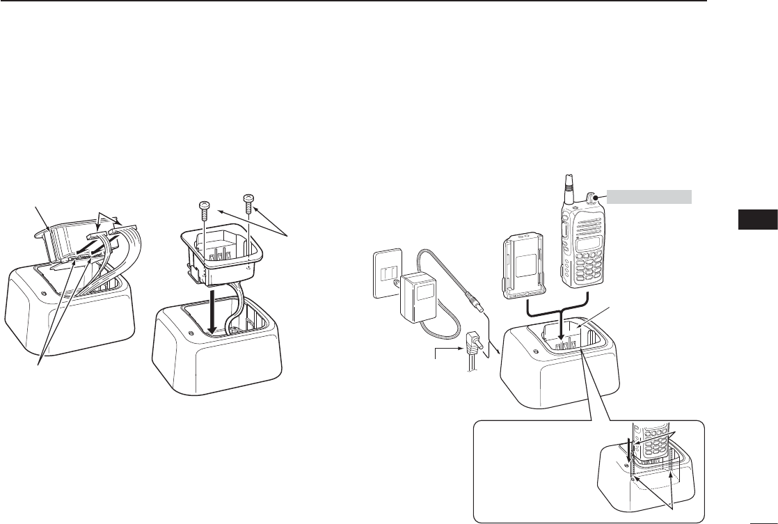
D AD-106 installation
➥ Connect the AD-106 charger adapter and the BC-119N or
BC-121N as below (q), then install the AD-106 into the
holder space of the BC-119N or BC-121N with the sup-
plied screws (w).
D Rapid charging with the BC-119N+AD-106
The optional BC-119N provides rapid charging of battery
packs. The following accessories are additionally required.
• AD-106 charger adapter.
• An AC adapter (may be supplied with BC-119N depending on the
charger versions) or the OPC-515L DC power cable.
7
BATTERY PACKS AND CASE
Screws
(supplied with
AD-106)
AD-106 Connectors
Plugs
qw
AD-106 charger
adapter is installed
in BC-119N.
AC adapter
(Not supplied with
some versions.)
Optional OPC-515L
(for 13.8 V power
source) can be used
instead of the AC
adapter.
Transceiver
Battery
pack
Turn power OFF
IMPORTANT!:
Ensure the guide lobes
on the battery pack are
correctly aligned with
the guide rails inside
the charger adapter.
Lobes
Guide rails
1
2
3
4
5
6
7
8
9
10
11
12
13
14
15
16
17
18
19
7BATTERY PACKS AND CASE
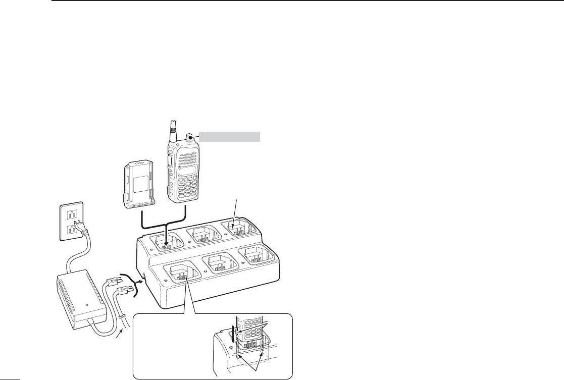
D Rapid charging with the BC-121N+AD-106
The optional BC-121N allows up to 6 battery packs to be
charged simultaneously. The following are additionally re-
quired.
• Six AD-106 charger adapters.
• An AC adapter (BC-157) or the DC power cable (OPC-656).
Battery case ■
(optional for some versions)
D Precaution
NEVER incinerate used battery cells since internal battery
gas may cause them to rupture.
NEVER expose a detached battery case to water. If the bat-
tery case gets wet, be sure to wipe it dry before using it.
NEVER short the terminals of the battery case. Also, cur-
rent may fl ow into nearby metal objects, such as a necklace,
etc. Therefore, be careful when carrying with, or placing near
metal objects, carrying in handbags, etc.
When installing battery cells, make sure they are all the same
brand, type and capacity. Also, do not mix new and old bat-
tery cells together.
Install conventional alkaline cells only. Other type of batter-
ies, such as Ni-Cd, Ni-MH, Li-Ion, are cannot be used.
Uninstall the alkaline cells when leaving the battery case un-
used for long time.
Keep battery contacts clean. It’s a good idea to clean battery
terminals once a week.
Alkaline cells have a shorter operating time in comparison
with Li-Ion battery cells. Also, operating time differs by brand,
as well as the model type of the alkaline cell being used.
Therefore, it is recommended that you use the Li-Ion battery
pack, or take spare alkaline cells with you when intending to
use the transceiver frequently, or for long periods.
Battery
pack
AD-106 charger
adapters are installed
in each slot.
AC adapter
(Purchased
separately)
Transceiver
Turn power OFF
DC power cable
(OPC-656)
(Connect with the
DC power supply;
13.8 V/at least 7 A)
IMPORTANT!:
Ensure the guide lobes
on the battery pack are
correctly aligned with
the guide rails inside
the charger adapter.
Guide rails
Lobes
31
32
7
BATTERY PACKS AND CASE
1
2
3
4
5
6
7
8
9
10
11
12
13
14
15
16
17
18
19
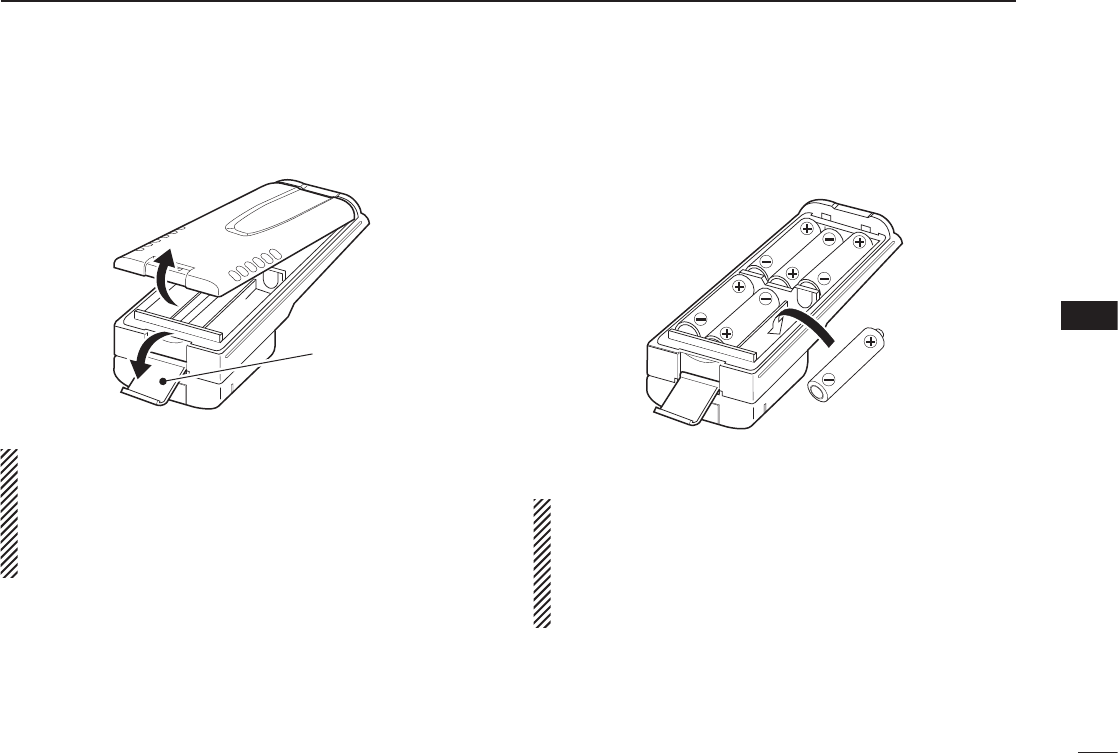
D Alkaline cells installation
Install 6 AA (LR6) size alkaline cells as described below.
q Release the latch, and open the cover.
Latch
CAUTION:
NEVER use your fi nger nail when releasing the latch.
Because the latch is tightly locked— you may injure your-
self. Instead, use something relatively fl at, like the edge of
a coin or the tip of a screwdriver, to carefully release the
latch.
w Install 6 AA (LR6) size alkaline cells.
• Install the conventional alkaline cells only.
• Be sure to observe the correct polarity.
e Attach the cover, then close. And lock the latch until it
makes a ‘click’ sound.
CAUTION:
• When installing batteries, make sure they are all the
same brand, type and capacity. Also, do not mix new
and old batteries together.
• Keep battery contacts clean. It’s a good idea to clean
battery terminals once a week.
33
7BATTERY PACKS AND CASE
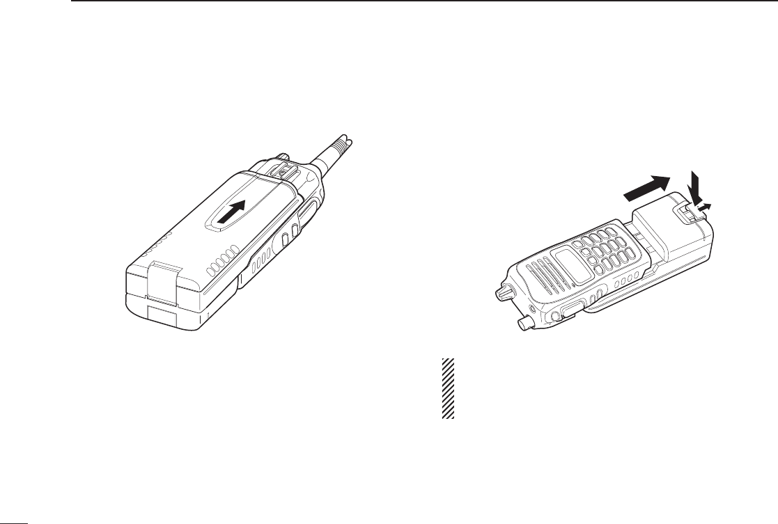
D Battery case attachment
Slide the battery case in the direction of the arrow.
• Slide the battery case until the transceiver’s battery release button
makes a ‘click’ sound.
To release the battery case:
Slide out the battery case’s battery release button in the di-
rection of the arrow (q), and then push the release button
in the direction of the arrow (w) as shown in the illustration
below. The battery pack is then released.
q
w
NEVER release or attach the battery case when the trans-
ceiver is wet or soiled. This may result water or dust get-
ting into the transceiver/battery case and may result in the
transceiver being damaged.
34
8
CLONING
1
2
3
4
5
6
7
8
9
10
11
12
13
14
15
16
17
18
19
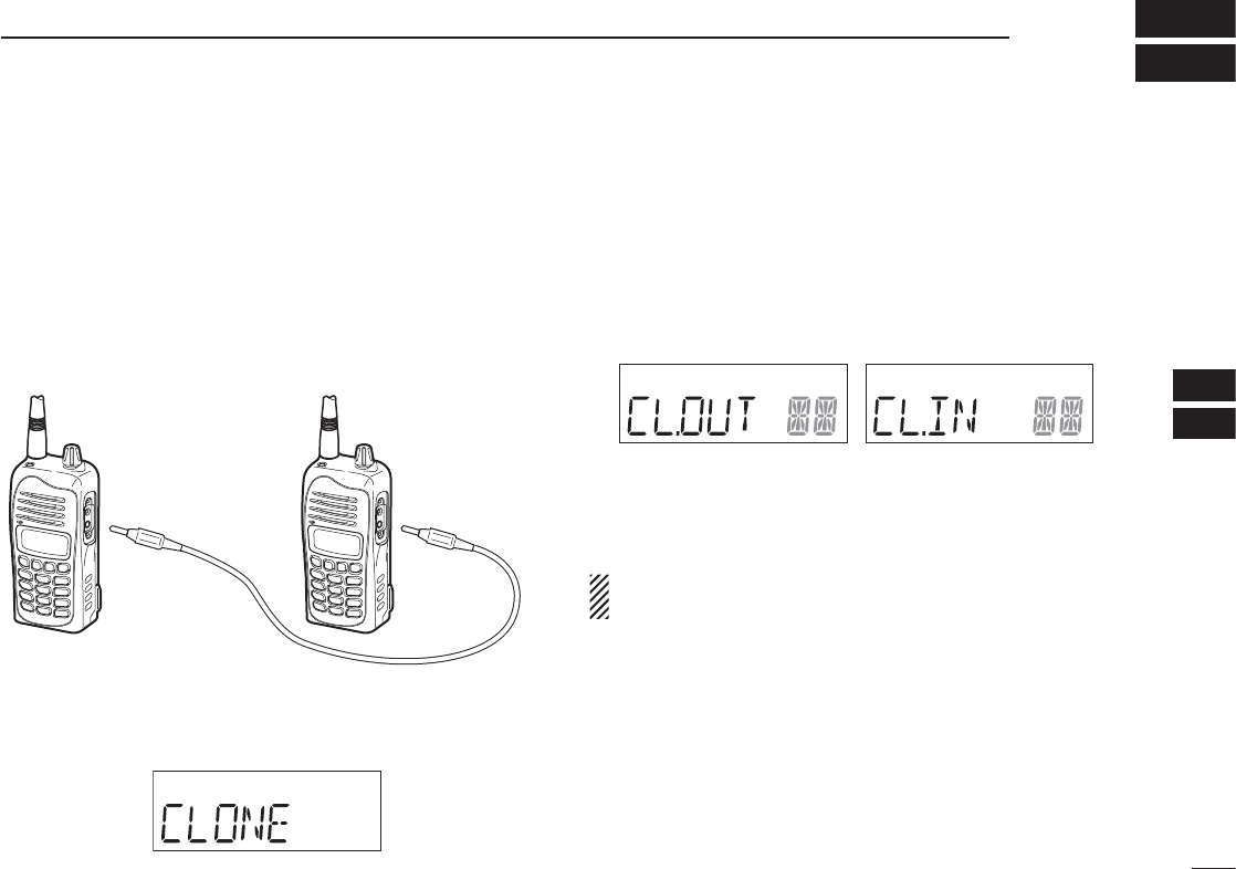
Cloning allows you to quickly and easily transfer the pro-
grammed data from one transceiver to another transceiver,
or, data from PC to a transceiver using the optional CS-A14
cloning software.
D Transceiver to transceiver cloning
q Connect the OPC-474 CLONING CABLE to [MIC/SP] jack
of the master and sub transceivers.
• The master transceiver is used to send data to the sub trans-
ceiver.
w While pushing and holding [MR], rotate [VOL] to enter
cloning mode (for operating the master transceiver only).
• “CLONE” appears and the transceivers enter the clone standby
condition.
e Push [PTT] on the master transceiver.
• “CL.OUT” appears in the master transceiver’s display.
• “CL.IN” appears automatically in the sub transceiver’s display.
r When cloning is fi nished, turn power OFF, then ON again
to exit cloning mode.
NOTE: Transceiver to transceiver cloning between IC-A14
and IC-A14S cannot be performed.
OPC-474
Master Sub
to the speaker
connector
to the speaker
connector
Master transceiver’s
indication during clone
Sub transceiver’s
indication during clone

D Cloning using PC
Data can be cloned to and from a PC (Microsoft® Windows®
2000/XP and Windows Vista™) using the optional CS-A14 CLON-
ING SOFTWARE and the optional OPC-478 (RS-232C type) or
OPC-478UC (USB type) CLONING CABLE. Consult the CS-A14
CLONING SOFTWARE HELP fi le for details.
D Cloning error
When the display as below appears, a cloning error has oc-
curred.
In this case, both transceivers automatically return to the
clone standby condition and cloning must be repeated.
Microsoft, Windows and Windows Vista are registered trademarks
or trademarks of Microsoft Corporation in the U.S.A. and/or other
countries.
35
8CLONING
36
9
TROUBLESHOOTING
1
2
3
4
5
6
7
8
9
10
11
12
13
14
15
16
17
18
19
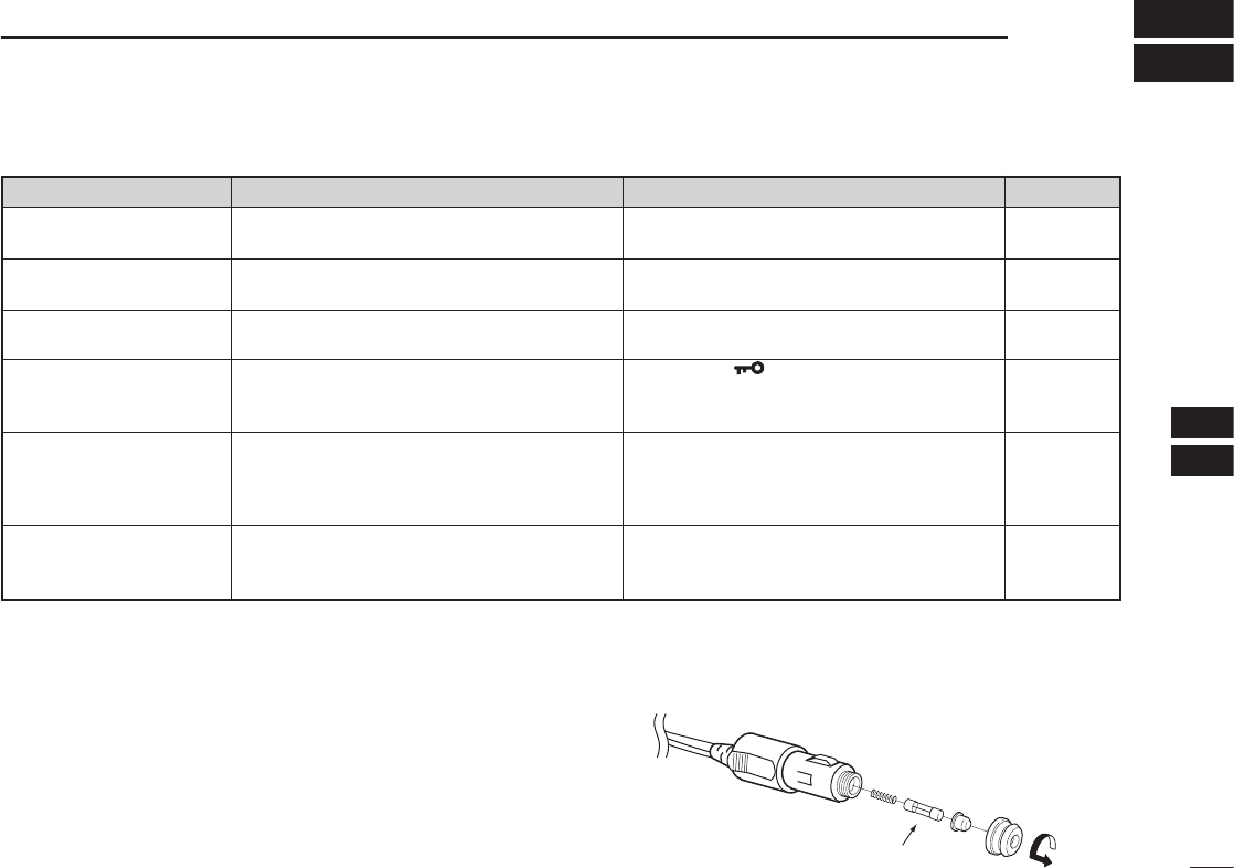
If your transceiver seems to be malfunctioning, please check the following points before sending it to a service center.
PROBLEM POSSIBLE CAUSE SOLUTION REF.
No power comes on. • The battery is exhausted. • Recharge the battery pack. pp. 29–31
• Bad connection for the battery pack. • Check the connection to the transceiver. p. 7
No sound comes from the • Squelch level is too deep. • Set squelch to the threshold point. p. 9
speaker. • Volume level is too low. • Set [VOL] to a suitable level.
Transmitting impossible. • WX channels or NAVI band is selected. • Set COM band in frequency mode. p. 8
• The battery is exhausted. • Recharge the battery pack. pp. 29–31
Operating frequency or • Lock function is activated. • Hold down [ ] for 2 seconds to turn the lock p. 9
memory channel can not
function OFF.
be changed.
Scan does not start. • All memory channels in the selected bank are • Set the “TAG” settings of desired channels. p. 20
not programmed as “TAG” channels.
• Squelch is open. • Set the squelch level to tighten. p. 9
• There is not more than 2 memorized channels • Program 2 or more memory channels. pp. 13, 14
No beep sounds. • Beep tones turned OFF. •
Turn the
beep tone ON;
¬
IC-A14:
Push [FUNC], then push [BEEP](8).
p. 22
¬
IC-A14S:
Turn the beep tone ON in set mode.
pp. 22
, 25
D CP-22 fuse replacement
If the fuse blows or the receiver stops functioning while oper-
ating with the optional CP-22 CIGARETTE LIGHTER CABLE, fi nd
the source of the problem if possible, and replace the dam-
aged fuse with a new rated one (FGB 8 A) as shown right.
Fuse 8 A

37
10 SPECIFICATIONS
D General
• Frequency coverage :
IC-A14 TX 118.000 to 136.975 MHz
RX 108.000 to 136.975 MHz
WX (Rx only) 161.650 to 163.275 MHz
IC-A14S TX/RX 118.000 to 136.975 MHz
• Mode : 6K00A3E
16K0G3E (IC-A14/Rx only)
• Channel spacing : 25 kHz
• Number of memory channels :
IC-A14 200 (20 CH × 10 BANKS)
IC-A14S 100
• Power supply requirement : Specifi ed Icom’s battery packs
7.4 V DC standard
• Usable temperature range : –10˚C to +60˚C (+14°F to +140°F)
• Current drain (at 7.4 V DC) :
Tx 1.5 A
Rx at stand by 50 mA typical
at AF max. 500 mA
• Antenna connector : BNC 50 Ω (nominal)
• Dimensions : 53(W) × 120(H) × 36.9(D) mm
(projections not included) 2
3⁄32(W) × 423⁄32(H) × 19⁄16(D) inch
• Weight : Approx. 180 g (6.35 oz)
(Without the battery pack and antenna.)
D Transmitter
• Output power : 5.0 W (PEP) typical
1.5 W (CW)
• Modulation : Low level modulation
• Modulation limiting : 70 to 100%
• Frequency stability : ±5 ppm
• Audio harmonic distortion : Less than 10% (at 60% mod.)
• Hum and noise ratio : More than 35 dB
• Spurious emissions : More than 46 dB (except operating
frequency ±62.5 kHz range)
• External MIC connector : 3-conductor 2.5(d) mm (1⁄10˝)/
150 Ω
D Receiver
• Receive system : Double conversion superhetero-
dyne
• Intermediate frequencies : 1st 46.35 MHz, 2nd 450 kHz
• Sensitivity :
COM band (6 dB S/N) –6 dBµ typical
NAVI band (6 dB S/N) –3 dBµ typical (IC-A14 only)
WX channels (12 dB SINAD) –13 dBµ typical (IC-A14 only)
• Squelch sensitivity (threshold) : AM Less than 0 dBµ
FM Less than –5 dBµ
(IC-A14 only)
• Selectivity : 6 dB (More than 7.5 kHz)
60 dB (Less than 25 kHz)
• Spurious response rejection : AM More than 60 dB
FM More than 30 dB
(IC-A14 only)
• Audio output power : More than 700 mW (internal SP)
( at 10% distortion with an 8 Ω More than 500 mW (external SP)
load, 30% mod.)
• Hum and noise : More than 35 dB at 30% mod.
• External SP connector : 3-conductor 3.5 (d) mm (1⁄8˝)/8 Ω
All stated specifi cations are subject to change without notice or obligation.

38
11
OPTIONS
1
2
3
4
5
6
7
8
9
10
11
12
13
14
15
16
17
18
19
D BATTERY PACKS
• BP-230N/BP-232N/BP-232H Li-Ion BATTERY PACKS
BP-230N: 7.4 V/980 mAh (typical); 950 mAh (minimum)
BP-232N: 7.4 V/2000 mAh (typical); 1900 mAh (minimum)
BP-232H: 7.4 V/2350 mAh (typical); 2250 mAh (minimum)
• BP-261 BATTERY CASE
Battery case for LR6 (AA) × 6 alkaline batteries.
D CHARGERS
• BC-119N DESKTOP CHARGER + AD-106 CHARGER ADAPTER
+ BC-145S AC ADAPTER
For rapid charging of battery packs. An AC adapter is supplied with
the charger depending on versions.
Charging time: approx. 3 hours when BP-232H is attached.
• BC-121N MULTI-CHARGER + AD-106 CHARGER ADAPTER (6 pcs.)
+ BC-157S AC ADAPTER
For rapid charging of up to 6 battery packs (six AD-106’s are re-
quired) simultaneously. An AC adapter should be purchased sepa-
rately. Charging time: approx. 3 hours when BP-232H is attached.
• BC-160 DESKTOP CHARGER + BC-145S AC ADAPTER
For rapid charging of BP-230N and BP-232H (Li-ion).
• BC-171 DESKTOP CHARGER + BC-147S AC ADAPTER
For regular charging of BP-230N and BP-232H (Li-ion).
• BC-179 DESKTOP CHARGER + BC-174 AC ADAPTER
For regular charging of BP-230N and BP-232H (Li-ion).
D MICROPHONE
• HM-173 SPEAKER MICROPHONE
Combination speaker and microphone.
D BELT CLIPS
• MB-94 BELT CLIP
Alligator type belt clip.
• MB-96F LEATHER BELT HANGER
Attaches with the supplied belt clip (Fixed type).
D DC CABLES
• CP-22 CIGARETTE LIGHTER CABLE
DC-DC converter is built-in. Charges the battery pack using 12/24 V
DC power source instead of the AC adapter for BC-171/179.
• OPC-515L DC POWER CABLE FOR BC-119N
Charges the battery pack using 13.8 V power source instead of the
AC adapter for BC-119N.
• OPC-656 DC POWER CABLE FOR BC-121N
Charges the battery pack using 13.8 V power source instead of the
AC adapter for BC-121N.
D OTHER OPTIONS
• CS-A14 CLONING SOFTWARE + OPC-478/UC CLONING CABLE
Provides quick and easy programming of items, such as memory
channels or set mode contents, from a PC using the cloning cable,
OPC-478 (RS-232C; DB-9 type) or OPC-478UC (USB type).
• MB-130 vehicle charger bracket
Vehicle mounting bracket for BC-160 battery charger.
• OPC-499 HEADSET ADAPTER CABLE
When using an optional headset (3rd party products) via the adapter,
the transceiver outputs your transmitted voice to the headset for
monitoring.
• OPC-474 CLONING CABLE
For data cloning between transceivers.
Available options may differ according to countries. Ask your authorized dealer for details.
39
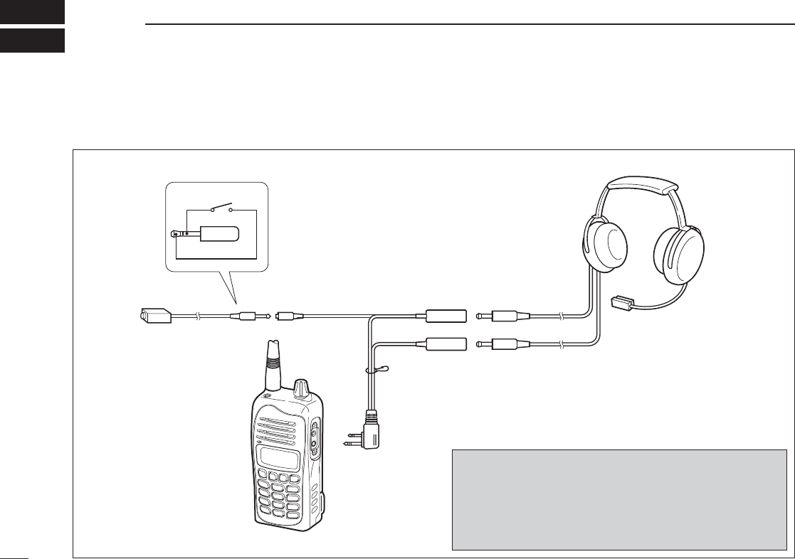
12 OPTIONAL HEADSET CONNECTION
D OPC-499 (HEADSET ADAPTER) connection
When using a headset (3rd party products) via the OPC-499 HEADSET ADAPTER, the transceiver outputs your transmitted voice
to the headset for monitoring. See “■ Side tone function” (p. 11) when setting the side tone level.
PTT
OPC-499
Transceiver
PTT switch
HEADSET
(Must be purchased
separately)
Use a PTT switch with a
3.5 mm (
1
⁄
8
˝) diameter
plug, if required.
NOTICE!
Some headsets do not work properly when used with the
IC-A14/S.
Therefore, ask your dealer for details about headsets com-
patible for operation with the IC-A14/S with the headset.

40
1
2
3
4
5
6
7
8
9
10
11
12
13
14
15
16
17
18
19
This equipment has been tested and found to comply with the
limits for a Class B digital device, pursuant to part 15 of the
FCC Rules. These limits are designed to provide reasonable
protection against harmful interference in a residential instal-
lation. This equipment generates, uses and can radiate radio
frequency energy and, if not installed and used in accordance
with the Instructions, may cause harmful interference to radio
communications. However, there is no guarantee that inter-
ference will not occur in a particular installation. If this equip-
ment does cause harmful interference to radio or television
reception, which can be determined by turning the equipment
off and on, the user is encouraged to try to correct the inter-
ference by one or more of the following measures:
• Reorient or relocate the receiving antenna.
• Increase the separation between the equipment and re-
ceiver.
• Connect the equipment into an outlet on a circuit differ-
ent from that to which the receiver is connected.
• Consult the dealer or an experienced radio/TV techni-
cian for help.
13
FOR CLASS B UNINTENTIONAL RADIATORS

41
MEMO

42
MEMO
1
2
3
4
5
6
7
8
9
10
11
12
13
14
15
16
17
18
19

1-1-32 Kamiminami, Hirano-ku, Osaka 547-0003, Japan
Printed on recycled paper with soy ink.
A-6631H-1EX-w
Printed in Japan
© 2007–2013 Icom Inc.