ICOM orporated 315500 VHF/UHF Amateur Transceiver User Manual 1
ICOM Incorporated VHF/UHF Amateur Transceiver 1
UserManual.wiki
>
ICOM orporated
>
315500 User Manual
>
User Manual 1
Contents
1.
User Manual 1
2.
User Manual 2
3.
User Manual 3
User Manual 1
Navigation menu
Upload a User Manual
Namespaces
Wiki Guide
HTML
PDF
Info
Views
User Manual
Discussion / Help
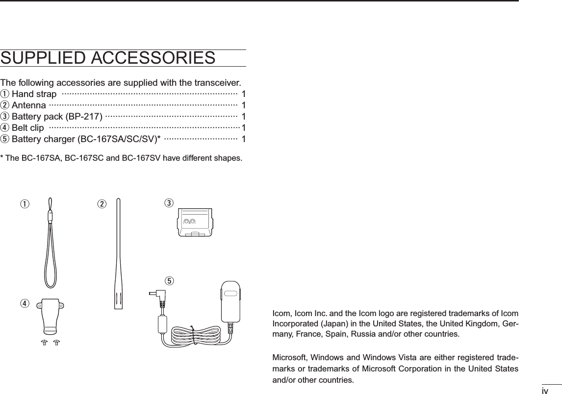
Navigation
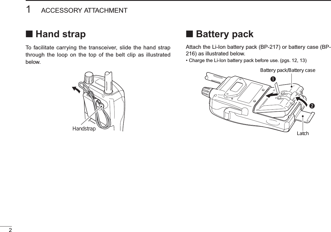
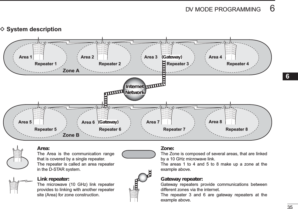
![vFOREWORD ····················································································· iEXPLICIT DEFINITIONS ··································································· iFEATURES ························································································ iIMPORTANT ······················································································ iPRECAUTIONS ············································································ii, iiiFCC INFORMATION ······································································· iiiSUPPLIED ACCESSORIES ···························································· ivTABLE OF CONTENTS ······························································ v–vii1 ACCESSORY ATTACHMENT················································· 1–2N Antenna ···················································································1N Belt clip ···················································································· 1N Hand strap ··············································································· 2N Battery pack ·············································································22 PANEL DESCRIPTION ···························································3–9N Front, top and side panels ·······················································3N Function display ·······································································83 BATTERY CHARGING ·······················································10–15N Caution ··················································································10N Regular charging ···································································12N Rapid charging·······································································13N Optional battery case ·····························································14N Battery information ································································14N External DC power operation ·················································154 BASIC OPERATION ···························································16–28N Power ON ··············································································16N Setting audio volume ·····························································16N Setting squelch level ······························································17N Monitor function ·····································································17N Mode selection·······································································18N [DIAL] function assignment ····················································20N Operating band selection ·······················································20N Setting a tuning step ······························································22N Setting a frequency ································································22N Lock function ··········································································24N Receiving ···············································································24N Operating mode selection ······················································25N Attenuator function ·································································25N Transmitting ············································································26N Transmit power selection ·······················································27N TV channel operation ·····························································275 REPEATER AND DUPLEX OPERATIONS ························29–33N Repeater operation ································································29N Duplex operation ····································································31N Auto repeater function ···························································32N 1750 Hz tone ·········································································336 DV MODE PROGRAMMING···············································34–46N About the D-STAR system ·····················································34N Call sign programming ···························································36N Repeater list ··········································································39N Repeater list programming ····················································40N Changing a repeater list·························································45N Clearing a repeater list ··························································46TABLE OF CONTENTS](https://usermanual.wiki/ICOM-orporated/315500.User-Manual-1/User-Guide-1070560-Page-6.png)
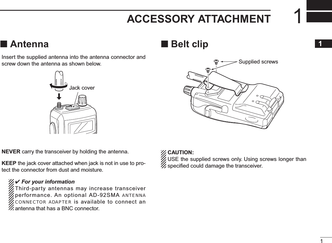
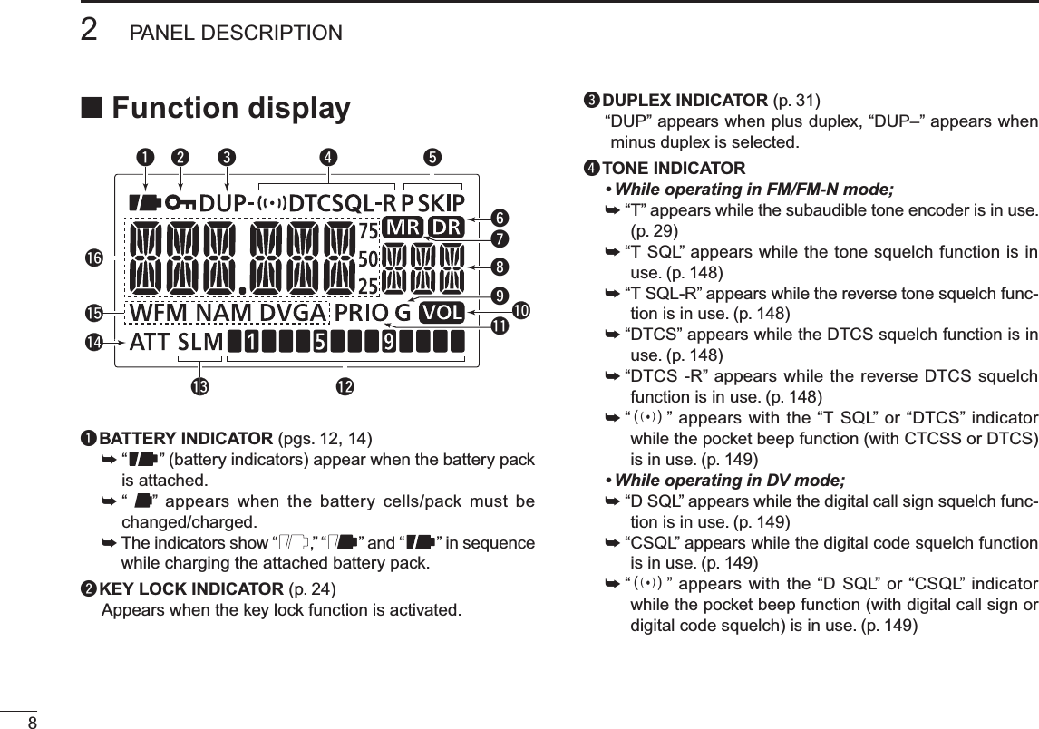
![32PANEL DESCRIPTION12345678910111213141516171819N Front, top and side panelsSpeakerKeypadInternal microphoneFunction displayqyutrweio!1!0q ANTENNA CONNECTOR (p. 1)Connects the supplied antenna.• An optional AD-92SMA adapter (p. 161) is available for connecting an antenna with a BNC connector.wPTT SWITCH [PTT] (p. 26)Push and hold to transmit, release to receive.e TX/RX INDICATOR [TX/RX] (pgs. 24, 26)Lights green while receiving a signal or when the squelch is open; lights red while transmitting.rSQUELCH KEY [SQL] (p. 17)±Push and hold to open the squelch temporarily and monitor the operating frequency.±While pushing and holding this key, rotate [DIAL] to ad-just the squelch level.tMENU •LOCK KEY [MENU ]±Push to enter menu screen indication ON and OFF. (p. 113)• Pushing [V/MHz] also exits from the menu screen.±Push and hold for 1 sec. to toggle the lock function ON and OFF. (p. 24)y POWER KEY [PWR]Push and hold for 1 sec. to turn the transceiver power ON and OFF. (p. 16)](https://usermanual.wiki/ICOM-orporated/315500.User-Manual-1/User-Guide-1070560-Page-11.png)
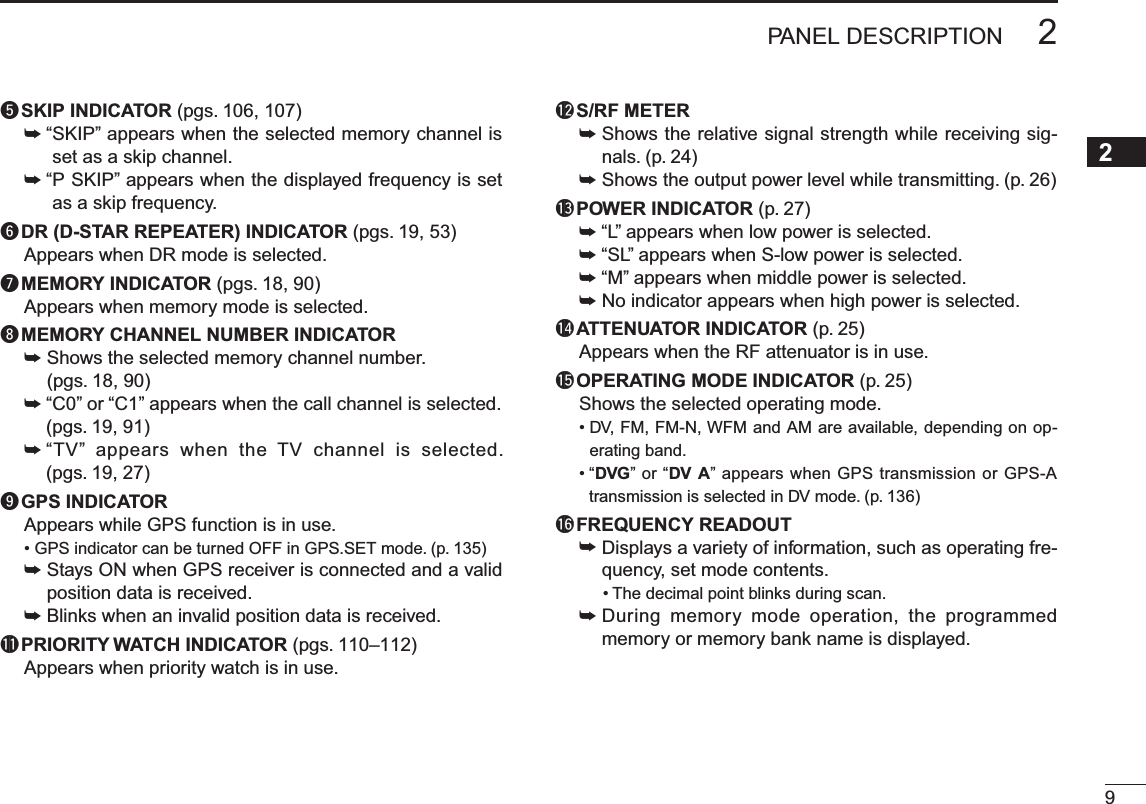
![42PANEL DESCRIPTIONSpeakerKeypadInternal microphoneFunction displayqyutrweio!1!0u VOLUME CONTROL KEY []/[]±Adjust audio volume level. (p. 17)±[]enters or sends the DTMF code ‘D.’ (pgs. 141–143)The function of tuning control and volume control can be traded. See page 20 for details.iCONTROL DIAL [DIAL]± Rotate to tune the operating frequency. (p. 22)±During memory mode, rotate to select the memory channel. (pgs. 18, 90)±While scanning, changes the scanning direction. (pgs. 102, 104, 105)±While pushing and holding [SQL], sets the squelch level. (p. 17)±After pushing [BAND] during memory mode operation, selects the programmed bank. (p. 94)±During menu screen operation, rotate to select the set items or values. (p. 113)The function of tuning control and volume control can be traded. See page 20 for details.o EXTERNAL SPEAKER/MICROPHONE JACK [SP/MIC]Connect a cloning cable, optional speaker microphone or headset, if desired.See page 161 for a list of available options.Be sure to turn power OFF before connectiong/discon-necting optional equipment to/from the [SP/MIC] jack.](https://usermanual.wiki/ICOM-orporated/315500.User-Manual-1/User-Guide-1070560-Page-12.png)
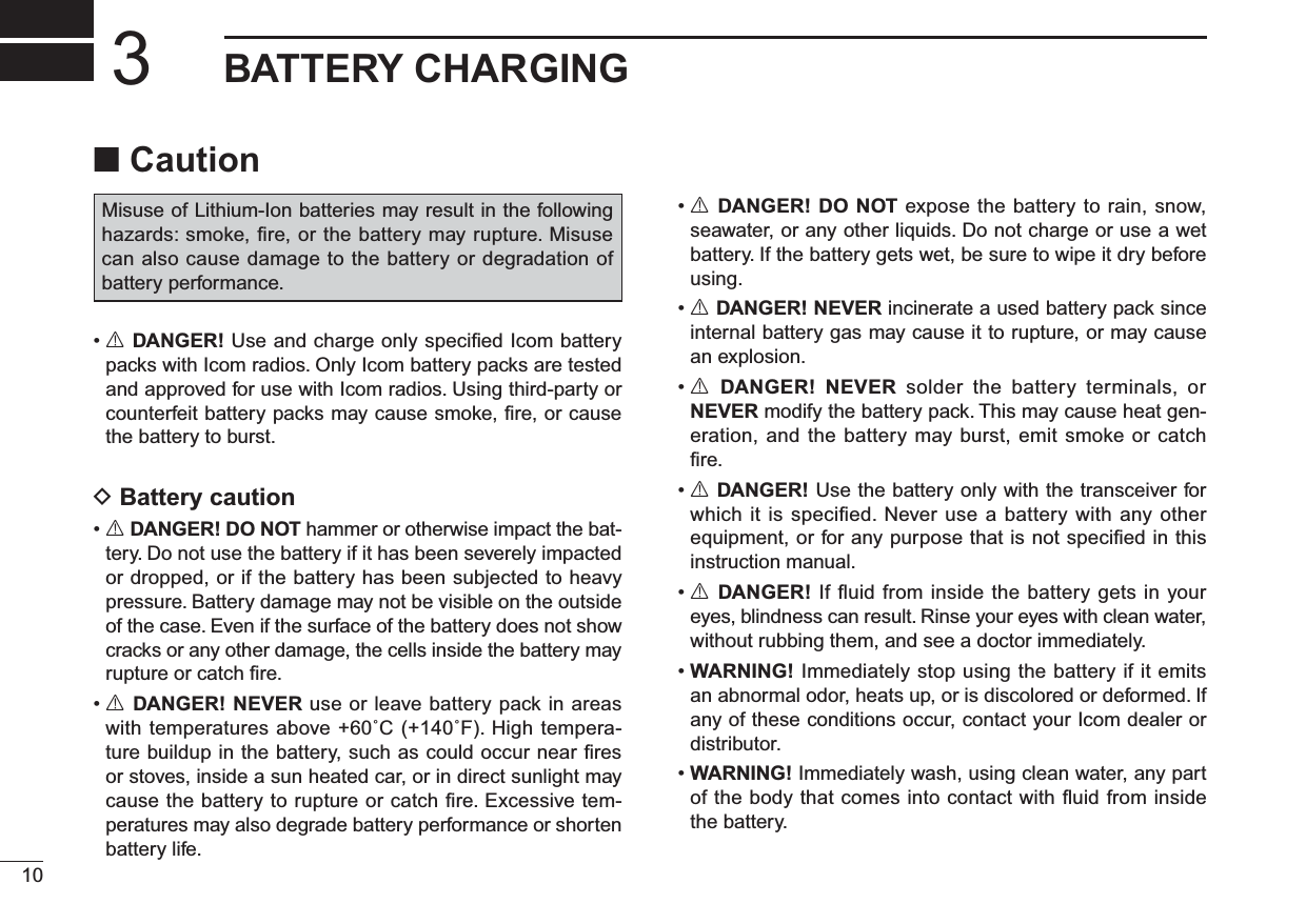
![52PANEL DESCRIPTION12345678910111213141516171819!0EXTERNAL DC IN JACK [DC IN]±Connects the supplied wall charger, BC-167SA/SC/SV, to charge the attached battery pack. (p. 12)±Connect an external DC power supply through the op-tional CP-12L, CP-19R or OPC-254L for external DC operation. (p. 15)!1 DATA JACK [DATA] (pgs. 72, 75)Connects a PC through the optional data communication cable, OPC-1529R, for low-speed data communication or connects a GPS receiver.D KEYPAD±Push to input numeral for frequency input, memory chan-nel selection, etc.±Push to enter or send the DTMF code. (pgs. 141–143)1 • VOLUME/DIAL KEY [1] • [V<=>D](1)±Numeral input and DTMF code: ‘1’±Push and hold for 1 sec. to exchange the assigned functions between [DIAL] and []/[]. (p. 20)2 • TUNING STEP KEY [2] • [TS](2)±Numeral input and DTMF code: ‘2’±Push and hold for 1 sec. to enter tuning step set mode. (p. 22)±During menu screen operation or select memory write mode, push to select the set items or values. (p. 113)3 • OUTPUT POWER KEY [3] • [LOW](3)±Numeral input and DTMF code: ‘3’±Push and hold for 1 sec. to select the output power. (p. 27)• Selects the transmit output power from high, mid, low and S-low.• While pushing and holding this key, [DIAL] rotation se-lects the output power.4 • DUPLEX KEY [4] • [DUP](4)±Numeral input and DTMF code: ‘4’±Push and hold for 1 sec. to select minus duplex, plus duplex, and simplex operation. (p. 31)• “DUP–” (minus duplex), “DUP” (plus duplex) and no indication (simplex) appear in order.• While pushing and holding this key, [DIAL] rotation se-lects the duplex operation.±During menu screen operation, push to select the upper layer. (p. 113)](https://usermanual.wiki/ICOM-orporated/315500.User-Manual-1/User-Guide-1070560-Page-13.png)
![62PANEL DESCRIPTION5 • SKIP KEY [5] • [SKIP](5)±Numeral input and DTMF code: ‘5’±Push and hold to turn the frequency skip function ON and OFF in VFO mode, or set the memory channel as the following skip channel in memory mode in order.• “SKIP” appears when memory skip, “PSKIP” appears when frequency skip and no indication appears when non skip channel is set.• While pushing and holding this key, [DIAL] rotation se-lects the skip condition.±During menu screen operation, push to enter or exit to/from the selected set items, etc. (p. 113)6 • MEMORY NAME KEY [6] • [M.N](6)±Numeral input and DTMF code: ‘6’±Push and hold for 1 sec. to turn the memory or bank name indication ON and OFF. (p. 96)• While pushing and holding this key, [DIAL] rotation se-lects the memory or bank indication.±During menu screen operation, push to select the lower layer. (p. 113)7 • TONE/DIGITAL SQUELCH KEY [7] • [TONE](7)/[DSQ](7)±Numeral input and DTMF code: ‘7’±During FM/FM-N mode operation, push and hold for 1 sec. to select repeater tone, tone squelch, tone squelch reverse, DTCS squelch, DTCS squelch reverse and no tone operation in se-quence. (p. 148)• Pocket beep function is available for tone squelch and DTCS squelch. (p. 149)±During DV mode operation, push and hold for 1 sec. to select digital call sign squelch, digital code squelch and no squelch operation in sequence. (p. 149)• Pocket beep function is available. (p. 149)8 • RX CALL SIGN SET KEY [8] • [RXCS](8)±Numeral input and DTMF code: ‘8’±During DV mode operation, push and hold for 1 sec. to set the received call signs (station and repeaters) to current call sign. (p. 50)9 • TONE SCAN/CALL SIGN KEY [9] • [T.SCAN](9)/[CS](9)±Numeral input and DTMF code: ‘9’±During FM/FM-N mode operation, push and hold for 1 sec. to start tone scan function. (p. 150)±During DV mode operation (including DR mode operation), push and hold for 1 sec. to enter the call sign mode. (p. 48, 57)](https://usermanual.wiki/ICOM-orporated/315500.User-Manual-1/User-Guide-1070560-Page-14.png)
![72PANEL DESCRIPTION20 • DTMF KEY [0] • [DTMF](0)±Numeral input and DTMF code: ‘0’±Push and hold for 1 sec. to select DTMF memory mode. (p. 141)VFO/MHz • SCAN KEY [V/MHz] • [SCAN](V/MHz)± DTMF code: ‘A’ ± Push to select VFO mode. (p. 18)±During VFO mode operation, push to select 1 MHz and 10 MHz tuning steps. (p. 22)±Push and hold for 1 sec. to enter scan type selec-tion mode. (pgs. 102, 104, 105)• Push again to start the scan.±Aborts numeral key input. (p. 23)±During menu screen operation, select memory write mode etc., or push to return to previous op-erating condition. (pgs. 92, 113)MEMORY/CALL • SELECT MEMORY WRITE KEY[M/CALL] • [S.MW](M/CALL)± DTMF code: ‘B’ ±Push to select memory mode, call channel, TV channel and weather channel. (pgs. 18, 19, 27, 90, 91, 152)±Push and hold for 1 sec. to enter select memory write mode. (p. 92)DR (D-STAR REPEATER) KEY [DR]±DTMF code: ‘C’±Push to select DR mode. (pgs. 19, 53)±During DR mode operation, push to enter the ac-cess repeater selection.VOLUME CONTROL (UP) KEY []±DTMF code ‘D.’ ±Adjust audio volume level. (p. 17)BAND • MODE KEY [BAND] • [MODE](BAND)± DTMF code: ‘1 (indication: E)’ ±During VFO mode operation, push to select an operating frequency band. (pgs. 20, 21)±During memory mode operation, push to enter memory bank group selection. (p. 94)±Push and hold for 1 sec. to select the operating mode. (p. 25). • UR KEY [.] • [UR](.)±DTMF code ‘# (indication: F).’±Inputs MHz digit for frequency input.±During DV mode operation (including DR mode operation), push and hold for 1 sec. to enter the station call sign selection mode.• Rotate [DIAL] to select the call sign.During other than DV mode operation, pushing and holding this key enters the station call sign selection mode with changing the operating mode to DV mode.](https://usermanual.wiki/ICOM-orporated/315500.User-Manual-1/User-Guide-1070560-Page-15.png)
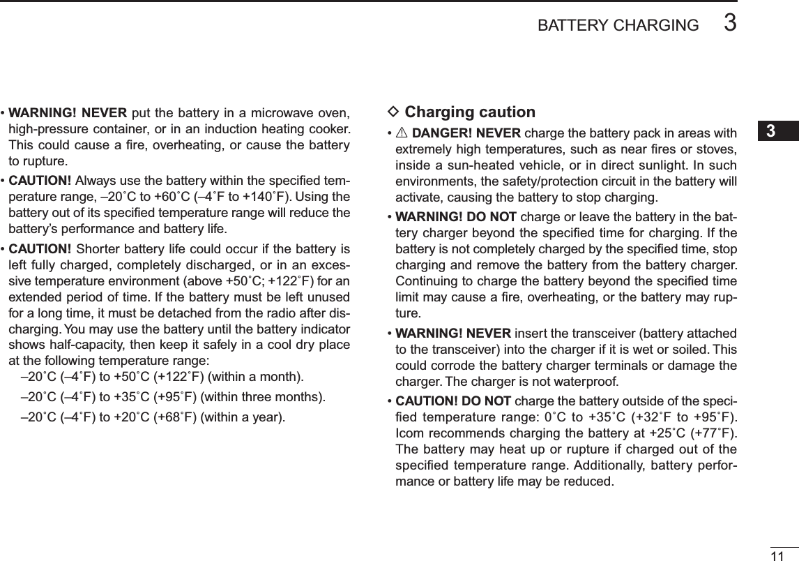
![123BATTERY CHARGINGN Regular chargingPrior to using the transceiver for the first time, the battery pack must be fully charged for optimum life and operation.DBattery indicatorsThe indicators show “ ,” “ ” and “ ” in sequence and “CHARGE” appears while charging (when the transceiver’s power is OFF). The indicators and “CHARGE” disappear when the battery pack is completely charged.DCharging note• Be sure to turn the transceiver power OFF.Otherwise the battery pack will not be charged completely or will take much longer to charge.• External DC power operation becomes possible when using an optional CP-12L, CP-19R or OPC-254L. The attached battery pack is also charged simultaneously, except during transmit. (see p. 15 for more details)• The external DC power supply voltage must be between 10–16 V to charge the battery pack and for operation when using an optional OPC-254L.• BC-167• CP-12L (Optional)• OPC-254L (Optional)to AC outletto cigarette lightersocket (12 V DC)to 12 V DC(power supply)White: +Black: _Transceiverto[DC IN]Turn power OFF while charging the battery pack.The BC-167SA, BC-167SC and BC-167SV have different shapes.• Charging time period: Approx. 6 hoursBP-217 • CP-19R (Optional)](https://usermanual.wiki/ICOM-orporated/315500.User-Manual-1/User-Guide-1070560-Page-20.png)
![133BATTERY CHARGING3N Rapid chargingThe optional BC-139 provides rapid charging of the battery pack.DCharging note• Be sure to turn the transceiver power OFF.Detach the battery pack from the transceiver then charge the battery pack by itself, or charge the battery with regular charging when the transceiver power cannot be turned OFF. Otherwise the battery pack will not be charged (charging indicator on the BC-139 blinks orange about 10 sec. after the battery pack is installed in BC-139).• The desktop charger, BC-139, can only charge BP-217 bat-tery packs. Other types of rechargeable battery, Ni-Cd or Ni-MH cannot be charged.• If the charging indicator blinks orange, there may be a problem with the battery pack or charger. If this occurs, try charging the battery pack alone, without the transceiver, or try using the standard (non-rapid) charger. Contact your dealer if you have problems charging a new battery pack.• The optional CP-12L and OPC-254L can be used instead of the supplied AC adapter. Connect one of these to the [DC 13.5V] jack in this case.• Charging period: approx. 2.5 hours (with BP-217)ATransceiver(with battery pack)Turn power OFF.Check the orientation.Battery packto AC outletBC-139 (optional)Desktop chargerto [AC ADAPTER]Adapter (suppliedwith BC-139)Charging indicatorCharging : OrangeFinished : GreenChargingterminalBC-123(suppliedwith BC-139)NOTE: If the charging indicator blinks orange for 10 sec. or more with the battery pack installed in the transceiver, try charging the BP-217 alone. You can also try charging the BP-217 alone using the standard (non-rapid) battery charger.](https://usermanual.wiki/ICOM-orporated/315500.User-Manual-1/User-Guide-1070560-Page-21.png)
![153BATTERY CHARGING3N External DC power operationAn optional cigarette lighter cable (CP-12L or CP-19R; for 12 V cigarette lighter socket) or external DC power cable (OPC-254L) can be used for external power operation. D Operating note• Power supply voltage must be between 10.0–16.0 V DC. NEVER CONNECT OVER 16 V DC directly into the [DC IN]jack of the transceiver.•BE SURE to use CP-12L,CP-19R or OPC-254L when con-necting a regulated 12 V DC power supply.Use an external DC-DC converter to connect the transceiver through optional CP-12L, CP-19R or OPC-254L to a 24 VDC power source.• The voltage of the external power supply must be within 10–16 V DC when using either CP-12L, CP-19R or OPC-254L, otherwise, use the battery pack.• Disconnect the power cables from the transceiver when not using it. Otherwise, the vehicle battery will become ex-hausted.• The power save function is deactivated automatically dur-ing external DC power operation.TransceiverBP-217• CP-12L (Optional)• CP-19R (Optional)• OPC-254L (Optional)to cigarette lightersocket (12 V DC)to 12 V DC(power supply)White: +Black: _to[DC IN]NOTE: Up to 5 W (approx.) of maximum output power is available when using external DC power. However, when the supplied voltage exceeds 14 V, the built-in protection circuit activates to reduce the transmit output power to 2.5 W (approx.).](https://usermanual.wiki/ICOM-orporated/315500.User-Manual-1/User-Guide-1070560-Page-23.png)
![16BASIC OPERATION4N Power ON± Push and hold [PWR] for 1 sec. to turn power ON.• Push and hold [PWR] for 1 sec. to turn power OFF.Opening message is selectable in DISP set mode.MENU ¶SET ¶DISP ¶OPN.MSG (p. 128)N Setting audio volume± Push [] or [] several times to adjust the audio level. • If squelch is closed, push and hold [SQL] while setting the audio level.• The display shows the volume level while setting.Minimum setting (no audio)Maximum settingVolume level indicatorBeep level is adjustable in SOUNDS set mode.MENU ¶SET ¶SOUNDS ¶BEEPLV (p. 128)](https://usermanual.wiki/ICOM-orporated/315500.User-Manual-1/User-Guide-1070560-Page-24.png)
![174BASIC OPERATION12345678910111213141516171819N Setting squelch levelThe squelch circuit mutes the received audio signal depend-ing on the signal strength. The transceiver has 9 squelch lev-els, a continuously open setting and an automatic squelch setting.±While pushing and holding [SQL], rotate [DIAL] to select the squelch level.• “LEVEL1” is loose squelch (for weak signals) and “LEVEL9” is tight squelch (for strong signals).• “AUTO” indicates automatic level adjustment by a noise pulse counting system.• “OPEN” indicates continuously open setting. (This selection is not available in DV mode.)[DIAL]Maximum levelAutomatic squelchN Monitor functionThis function is used to listen to weak signals without disturb-ing the squelch setting or to open the squelch manually even when mute functions such as the tone squelch are in use.± Push and hold [SQL] to monitor the operating frequency.• The 1st segment of the S-meter blinks.The 1st segment blinksThe [SQL] key can be set to ‘sticky’ operation in FUNC set mode (SET). See page 123 for details.MENU ¶SET ¶FUNC ¶MONI (p. 123)](https://usermanual.wiki/ICOM-orporated/315500.User-Manual-1/User-Guide-1070560-Page-25.png)
![184BASIC OPERATIONN Mode selectionD VFO modeVFO mode is used to set the desired frequency.± Push [V/MHz] to select VFO mode.• VFO mode indicationWhat is VFO?VFO is an abbreviation of Variable Frequency Oscillator. Fre-quencies for both transmitting and receiving are generated and controlled by the VFO.D Memory modeMemory mode is used for operation on memory channels which store programmed frequencies.qPush [M/CALL] to select memory mode.•“ ” appears when memory mode is selected.• Push [M/CALL] several times to select call channels/TV* chan-nels/Weather† channels. Call/TV*/Weather† channels can be selected in sequence.• Memory mode indicationAppearwRotate [DIAL] to select the desired memory channel.• Only programmed memory channels can be selected.• Enter the memory channel directly to select the desired memory channel. (p. 91)• See p. 92 for memory programming details. *Appears only when TV channels are programmed via the CS-80/880 (free download software). †Available for the U.S.A. version only.Set the attenuator function ON (p. 25) if the received signal is blocked by another radio transmitter when using a third party high-gain antenna.](https://usermanual.wiki/ICOM-orporated/315500.User-Manual-1/User-Guide-1070560-Page-26.png)
![D Call/TV*/Weather† channelsCall channels are used for quick recall of most-often used frequencies. *Appears only when TV channels are programmed via the CS-80/880 (free download software). †Available for the U.S.A. version only.q Push [M/CALL] several times to select call channels/TV channels/Weather channels.• Memory/Call/TV/Weather channels can be selected in se-quence.wRotate [DIAL] to select the desired channel.• Call channel indication• TV channel indication• Weather channel indicationTV reception is available for analog TV broadcasting only, but it is not available for digital TV bradcasting.D DR (D-STAR Repeater) modeDR (D-STAR Repeater) mode is used for D-STAR repeater operation. In this mode, you can select the pre-programmed repeaters and UR (your call sign) by using [DIAL].D-STAR is an abbreviation for Digital Smart Technologies for Amateur Radio.qPush [DR] to select DR mode.•“ ” appears when DR mode is selected.• DR mode indicationAppearwRotate [DIAL] to select the desired access repeater.• While rotating [DIAL], S/RF-meter indicates group number.• Only programmed access repeaters in RPT-L menu can be se-lected. See p. 40 for RPT-L (repeter lists) programming details.MENU ¶RPT-L ¶ADD-L (p. 40)194BASIC OPERATION12345678910111213141516171819](https://usermanual.wiki/ICOM-orporated/315500.User-Manual-1/User-Guide-1070560-Page-27.png)
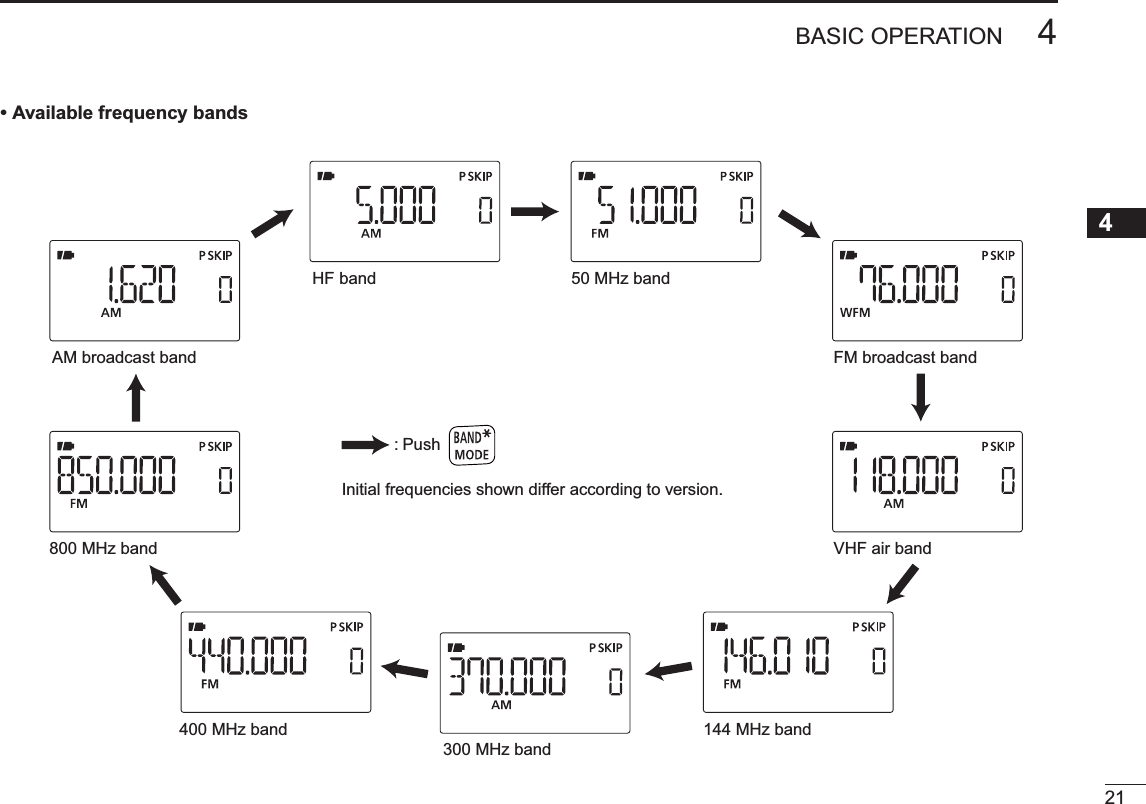
![N [DIAL] function assignmentThe [DIAL] control can be used as an audio volume con-trol instead of []/[] keys to suit your preference. However, when [DIAL] functions as an audio volume, []/[] keys function as tuning controls. ±Push and hold [V<=>D](1) for 1 sec. to toggle the dial func-tion between tuning dial and audio volume.Appears• The following functions are switched between [DIAL] and []/[].[DIAL] []/[]Frequency, Memory channel, Squelch level, Scanning directionAudio volume setN Operating band selectionThe transceiver can receive the AM broadcast, HF bands, 50 MHz, FM broadcast, VHF air, 144 MHz, 300 MHz, 400 MHz or 800 MHz* bands.±In VFO mode, push [BAND] several times to select the desired frequency band.• If VFO mode is not selected, such as a memory channel/call channel/TV channel/Weather channel, push [V/MHz] to select VFO mode first, then push [BAND] to select the desired band.Available frequency bands are different depending on ver-sion. See the specification for details. (pgs. 159, 160) *Some frequency ranges are blocked for the U.S.A. ver-sion by regulation.• 144 MHz band• 400 MHz band204BASIC OPERATION](https://usermanual.wiki/ICOM-orporated/315500.User-Manual-1/User-Guide-1070560-Page-28.png)
![224BASIC OPERATIONN Setting a tuning stepThe tuning step can be selected for each frequency band. The following tuning steps are available for the IC-80AD.• 5.0 kHz* • 6.25 kHz* • 8.33 kHz†• 9.0 kHz‡• 10.0 kHz• 12.5 kHz • 15.0 kHz* • 20.0 kHz • 25.0 kHz • 30.0 kHz• 50.0 kHz • 100.0 kHz • 125.0 kHz • 200.0 kHz* Appears for bands below the 600 MHz only. † Appears for the VHF air band only.‡ Appears for the AM broadcast band only.D Tuning step selectionqPush [V/MHz] to select VFO mode, if necessary.wPush [BAND] to select the desired frequency band.ePush and hold [TS](2) for 1 sec. to enter tuning step set mode.• While pushing and holding [TS](2), rotating [DIAL] is also se-lectable tuning step.rRotate [DIAL] to select the desired tuning step.tPush [TS](2) (or [V/MHz]) to return to VFO mode.[DIAL]5 kHz tuning stepN Setting a frequencyD Using the dialqPush [V/MHz] to select VFO mode, if necessary.wSelect the desired frequency band with [BAND].eRotate [DIAL] to select the desired frequency.• The frequency changes according to the preset tuning steps. See the previous content to set the tuning step.• When VFO mode is selected, push [V/MHz] then rotate [DIAL] to change the frequency in 1 MHz steps, or push [V/MHz] again then rotate [DIAL] to change the frequency in 10 MHz steps. Push [V/MHz] again to cancel it.)[DIAL][DIAL] changes the frequency according to the selected tuning step.After pushing [V/MHz] on VFO mode, [DIAL] changes the frequency in 1 MHz/10 MHz steps.](https://usermanual.wiki/ICOM-orporated/315500.User-Manual-1/User-Guide-1070560-Page-30.png)
![234BASIC OPERATION12345678910111213141516171819Depending on the tuning step setting, it may not be possible to input a 1 kHz digit. In this case, enter “0” as 1 kHz digit, then ro-tate [DIAL] to set the desired frequency.• Entering 145.580 MHz•Entering79.300 MHz• Editing to 684 kHz• Changing 100 kHz and belowEditing 145.580 MHz to 145.640 MHzPush to cancel numeral input.D Using the keypadThe frequency can be directly set via numeric keys.• If a frequency outside the frequency range is en-tered, the previously displayed frequency is auto-matically recalled after entering last digit.q Push [V/MHz] to select VFO mode, if nec-essary.wEnter the desired frequency via the keypad.](https://usermanual.wiki/ICOM-orporated/315500.User-Manual-1/User-Guide-1070560-Page-31.png)
 for 1 sec. to turn the lock func-tion ON and OFF.• “ ” appears while the lock function is activated.•[PWR],[]/[],[SQL],[PTT] and [ ](MENU) are operable while the lock function is activated.• The squelch control and volume control can be used while the lock function is in use with default setting. Either or both the squelch control and volume control can also be locked in set mode.MENU ¶SET ¶FUNC ¶LOCK (p. 125)AppearsN ReceivingMake sure a charged battery pack (BP-217) or brand new alkaline batteries (BP-216) are installed (pgs. 2, 14).qPush and hold [PWR] for 1 sec. to turn power ON.w Push [] or [] to set the desired audio level. (p. 16)• The frequency display shows the volume level while setting.eSet the receiving frequency. (p. 23)rSet the squelch level. (p. 17)• While pushing and holding [SQL], rotate [DIAL].• The first click of [DIAL] indicates the current squelch level.• “LEVEL 1” is loose squelch (for weak signals) and “LEVEL 9” is tight squelch (for strong signals).• “AUTO” indicates automatic level adjustment by a noise pulse counting system.• Push and hold [SQL] to open the squelch manually.t When a signal is received:• Squelch opens and audio is output.• The S/RF-meter shows the relative signal strength level.q [PWR]e Set frequencyr Set squelch levelw Set audio levele Select bandr Push for settingthe squelch(Push to monitor)](https://usermanual.wiki/ICOM-orporated/315500.User-Manual-1/User-Guide-1070560-Page-32.png)
 for 1 sec. several times to select the desired operating mode.• While pushing and holding [MODE](BAND), rotate [DIAL] is also available to select operating mode.[DIAL] + [DIAL]N Attenuator functionThe attenuator prevents distortion of a desired signal by very strong signals near the desired frequency or when very strong electric fields, such as from a broadcasting station, are present at your location. The attenuation is about 10 dB.q Enter “ATT” in FUNC set mode (in SET).MENU ¶ SET ¶ FUNC ¶ATT (p. 122) (Push [MENU ]), (Push [](2)/[](8), then push [ ](5).)w Push [](2) or [](8) to select “ON” or “OFF.”e Push [](5) (or [](4)) to return to set mode, and push [V/MHz] to return to frequency indication.• “ATT” appears on the function display when “ON” is selected.Appears](https://usermanual.wiki/ICOM-orporated/315500.User-Manual-1/User-Guide-1070560-Page-33.png)
![264BASIC OPERATIONN TransmittingCAUTION: Transmitting without an antenna will damage the transceiver.NOTE: To prevent interference, push and hold [SQL] to listen on the channel before transmitting.Tx/RxMicrophoneindicatorq Set the operating frequency. (p. 23)• Transmission is available on the 144 MHz/440 MHz amateur bands only.• Select output power if desired. See next page for details.w Push and hold [PTT] to transmit.• Tx/Rx indicator lights red.• S/RF meter shows the output power level.e Speak into the microphone using your normal voice level.• DO NOT hold the transceiver too close to your mouth or speak too loudly. This may distort your speech.rRelease [PTT] to return to receive.WARNING!NEVER continuously transmit for long periods of time. When the transceiver is used for continuous prolonged transmission at high power, the transceiver radiates heat to protect itself from overheating and transceiver’s chassis will become hot. This may cause a burn.DO NOT operate the transceiver in a situation that will obstruct heat dissipation, especially if the transceiver is operated with an external power supply. Heat dissipation may be affected, and it may cause a burn, warp the casing or damage the transceiver.NOTE: Transmit power set 2.5 W (MID) automatically when the transceiver radiates heat.CONNECT the rated range voltage when using external power supply.](https://usermanual.wiki/ICOM-orporated/315500.User-Manual-1/User-Guide-1070560-Page-34.png)
 for 1 sec. to toggle the trans-mit output power between High (5W*), Mid (2.5 W*), Low (0.5 W*) and S-Low (0.1 W*). *approx.• While pushing and holding [LOW](3), rotate [DIAL] is also avail-able to select transmit power.[DIAL]AppearsONLY S-Low power operation is available while using BP-216.S-Low power transmissionLow power transmissionMid. power transmissionHigh power transmissionN TV channel operationTV channel operation is available only when TV channels are programmed using the CS-80/880 (free download software).(p. 161)D TV channel receivingqPush [M/CALL] several times to select TV channels.• “TV” and channel number appear.wRotate [DIAL] to select the desired channel.• While pushing and holding [BAND], rotating [DIAL] selects the all channels including skip channel.[DIAL] TV mode indicationChannel indicationTV reception is available for analog TV broadcasting only, but it is not available for digital TV bradcasting.274BASIC OPERATION12345678910111213141516171819](https://usermanual.wiki/ICOM-orporated/315500.User-Manual-1/User-Guide-1070560-Page-35.png)
![D Skip channel settingUnwanted channels can be skipped for rapid selection, etc.qPush [M/CALL] several times to select TV channels.• “TV” and channel number appear.wRotate [DIAL] to select the channel to be skipped.• To clear the skip setting, rotate [DIAL] while pushing and holding [BAND] to select a skip channel.• While pushing and holding [SKIP](5), rotating [DIAL] also selects a skip channel.ePush and hold [SKIP](5) for 1 sec. to toggle the skip setting ON and OFF.• “SKIP” appears when the channel is set as skip channel.[DIAL]AppearsD Automatic TV channel programmingTV channels can be programmed automatically.qPush [M/CALL] several times to select TV channels.• “TV” and channel number appear.w Push and hold [SCAN](V/MHz) for 1 sec. to start TV channel programming.• The programming will automatically stop after scanning all channels.284BASIC OPERATION](https://usermanual.wiki/ICOM-orporated/315500.User-Manual-1/User-Guide-1070560-Page-36.png)
 for 1 sec. to activate the subaudible tone encoder, according to re-peater requirements.• “T” appears. Refer to p. 117 for tone frequency settings.rPush and hold [PTT] to transmit.• The displayed frequency automati-cally changes to the transmit fre-quency (repeater input frequency).• If “OFF” appears, check the off-set frequency or shift direction. (p. 30)While receiving While transmittingtRelease [PTT] to receive.y Push and hold [SQL] to check whether the other station’s transmit signal can be directly received or not. U.S.A. and Korean versions:Auto repeater function uses standard values of the re-peater tone frequency and offset frequency.](https://usermanual.wiki/ICOM-orporated/315500.User-Manual-1/User-Guide-1070560-Page-37.png)
![305REPEATER AND DUPLEX OPERATIONSDChecking the repeater input signalThe transceiver can check whether the other station’s trans-mit signal can be received directly or not, by listening on the repeater input frequency.±Push and hold [SQL] to check whether the other station’s transmit signal can be received directly or not.• When the other station’s signal can be directly received, move to a non-repeater frequency to use simplex. (duplex OFF)Indication while receivingReceives –0.6 MHz shift frequencyBlinks while pushing and holding LPush and holdDOff band indicationIf the transmit frequency is out of the amateur band, the off band indication, “OFF,” appears on the display when [PTT] is pushed. Check the offset frequency or duplex direction in this case. (p. 31) U.S.A. and Korean versions:Auto repeater function uses standard values of the offset frequency. CONVENIENT!Tone scan function: When you don’t know the subaudible tone used for a repeater, the tone scan is convenient for de-tecting the tone frequency.±Push and hold [T.SCAN](9) for 1 sec. to start the tone scan. See p. 150 for more information.](https://usermanual.wiki/ICOM-orporated/315500.User-Manual-1/User-Guide-1070560-Page-38.png)
![315REPEATER AND DUPLEX OPERATIONS12345678910111213141516171819N Duplex operationDSetting offset frequencyq Enter “OFFSET” in DUP.T menu.MENU ¶ DUP.T ¶OFFSET (p. 117) (Push [MENU ]), (Push [](2)/[](8), then push [ ](5).)w Push []/[] (or rotate [DIAL]) to set the offset fre-quency.e Push [](5) to return to DUP.T menu, and then push [MENU ] to return to frequency indication.0.6 MHz offsetNo offset frequencyOffset frequency settingDSetting duplex direction±Push and hold [DUP](4) for 1 sec. to select “DUP–” (nega-tive offset) or “DUP” (positive offset).• “DUP–” or “DUP” indicates the transmit frequency for minus shift or plus shift, respectively.• When offset frequency is 0.6 MHz–Duplex exampleReceivingTransmitting+Duplex exampleReceivingTransmittingU.S.A. and Korean versions:Auto repeater function has priority over the manual duplex setting. If the transmit frequency changes after setting, the auto repeater function may have changed the duplex setting.](https://usermanual.wiki/ICOM-orporated/315500.User-Manual-1/User-Guide-1070560-Page-39.png)
![325REPEATER AND DUPLEX OPERATIONSN Auto repeater functionThe U.S.A. and Korean versions automatically use standard repeater settings (duplex ON/OFF, duplex direction, tone encoder ON/OFF) when the operating frequency falls within or outside of the general repeater output frequency range. The offset and repeater tone frequencies are not changed by the auto repeater function. Reset these frequencies, if necessary.DFrequency range and offset direction• U.S.A. version• Korean versionFREQUENCY RANGE SHIFT DIRECTION439.000–440.000 MHz “DUP–” appearsq Enter “AUTORP” in FUNC set mode (SET). MENU ¶ SET ¶ FUNC ¶AUTORP (p. 124) (Push [MENU ]), (Push [](2)/[](8), then push [ ](5).)w Push [](2) or [](8) to select the auto repeater setting.U.S.A. version: • “RPT1” : Activates duplex only. (default) • “RPT2” : Activates duplex and tone. • “OFF” : Auto repeater function is turned OFF.Korean versions: • “ON” : Activates duplex and tone. (default) • “OFF” : Auto repeater function is turned OFF.e Push [ ](5) to return to FUNC set mode, and then push [MENU ] to return to frequency indication.Auto repeater setting U.S.A. versionKorean versionFREQUENCY RANGE SHIFT DIRECTION147.000–147.395 MHz “DUP” appears442.000–444.995 MHz “DUP” appears447.000–449.995 MHz “DUP–” appears145.200–145.495 MHz146.610–146.995 MHz “DUP–” appearsU.S.A./KOREAN versions only](https://usermanual.wiki/ICOM-orporated/315500.User-Manual-1/User-Guide-1070560-Page-40.png)
 for 1 sec. to select DTMF memory.w Push [](8) several times (or rotate [DIAL] counter-clock-wise) until “T-CALL” appears.e Push [ ](5) to set.rPush [V/MHz] to exit DTMF memory.t Set the receive frequency (repeater output frequency).y Set the shift direction of the transmit frequency. (–DUP or +DUP; see p. 31 for details.)u While pushing [PTT], push [SQL] to transmit a 1750 Hz tone burst signal.• If “OFF” appears, check the offset frequency or shift direction. (p. 110)• The displayed frequency automatically changes to the transmit frequency (repeater input frequency).iPush and hold [PTT] to transmit.oRelease [PTT] to receive.!0 Push and hold [SQL] to check whether the other station’s transmit signal can be received directly or not, by listening on the repeater input frequency.](https://usermanual.wiki/ICOM-orporated/315500.User-Manual-1/User-Guide-1070560-Page-41.png)
![366DV MODE PROGRAMMINGN Call sign programmingFour types of current call sign memory are available; “MY” (my call sign=your own call sign) “UR” (your call sign=other sta-tion call sign) “RPT1” (access repeater call sign) and “RPT2” (link repeater call sign). Each call sign can be programmed with up to 8 characters.In addition, "MY" can store up to 6 call signs, and "UR" can store up to 60 call signs in the call sign memory. Up to 300 repeater call signs can be stored in the repeater list.DYour own call sign programmingYour own call sign must be programmed for both digital voice and low-speed data communications (including GPS trans-mission).qEnter “MY” in call sign screen.MENU ¶ CALL-S ¶MY (Push [MENU ]), (push [](2)/[](8), then push [ ](5).)• MY call sign screen is displayed.w Push [](2) or [](8) to select the desired call sign mem-ory, “MY1” to “MY6.” ePush [](6) to enter call sign programming mode.• The 1st digit blinks.r Push [](2) or [](8) to select the desired character or code.• Push [](6) to move the cursor right; push [](4) to move the cursor left.tRepeat the step r to enter your own call sign.• Up to an 8 digit of call sign can be set.• If an unwanted character is entered, push [](6) or [](4) to select the character, then push [CLR](1) to erase the selected character, or push and hold [CLR](1) for 1 sec. to erase all char-acters following the cursor.• To program a note (up to 4 characters, for operating radio type, area, etc.), go to step y, otherwise go to step i.y Push [](6) several times to set the cursor beside “/” indi-cation.](https://usermanual.wiki/ICOM-orporated/315500.User-Manual-1/User-Guide-1070560-Page-44.png)
 to store the programmed call sign with note and return to call sign screen.oPush [MENU ] to return to frequency indication.D Station call sign programming Station call sign must be programmed to call a specific sta-tion as well as for repeater operation in both digital voice and low-speed data communications.qEnter “UR” in call sign screen. MENU ¶ CALL-S ¶UR (Push [MENU ]), (push [](2)/[](8), then push [ ](5).)• UR (Your) call sign screen is displayed.w Push [](2) or [](8) to select the desired call sign mem-ory, “U01” to “U60.”ePush [](6) to enter call sign programming mode.• The 1st digit blinks.r Push [](2) or [](8) to select the desired character or code.• Push [](6) or [](4) to move the cursor right or left, respectively.](https://usermanual.wiki/ICOM-orporated/315500.User-Manual-1/User-Guide-1070560-Page-45.png)
 or [](4) to select the character, then push [CLR](1) to erase the selected character, or push and hold [CLR](1) for 1 sec. to erase all char-acters following the cursor.y Push [ ](5) to store the programmed call sign and return to UR (Your) call sign screen.uPush [MENU ] to return to frequency indication. For your informationThe IC-80AD has a call sign edit record function.When editing a call sign stored in a call sign memory (or reg-ular memory/call channel), the default setting is to store the edited call sign into blank channel automatically ("FULL" is displayed when all call sign memory is programmed).The edited call sign can be over-written when the setting of the EDIT R (Edit record) is set to OFF or SEL. (p. 132)However, you must manually over-write a reprogrammed call sign in regular memory/call channels (temporary operation without over-writing is possible).D Current repeater call sign programming “RPT1” or “RPT2” can store current call only, and repeater call signs must be stored in the repeater list (p. 39).qEnter “RPT1” or “RPT2” in call sign screen. MENU ¶ CALL-S ¶RPT1 or RPT2 (Push [MENU ]), (push [](2)/[](8), then push [ ](5).)• RPT1/RPT2 call sign screen is displayed.wPush [](6) to enter call sign programming mode.• The 1st digit blinks.e Push [](2) or [](8) to select the desired character or code.• Push [](6) or [](4) to move the cursor right or left, respectively.r Repeat the step e to enter the desired repeater call sign.• Up to an 8 digit call sign can be set.• If an unwanted character is entered, push [](6) or [](4) to select the character, then push [CLR](1) to erase the selected character, or push and hold [CLR](1) for 1 sec. to erase all char-acters following the cursor.t Push [ ](5) to store the programmed call sign and returns to call sign screen.yPush [MENU ] to return to frequency indication.](https://usermanual.wiki/ICOM-orporated/315500.User-Manual-1/User-Guide-1070560-Page-46.png)
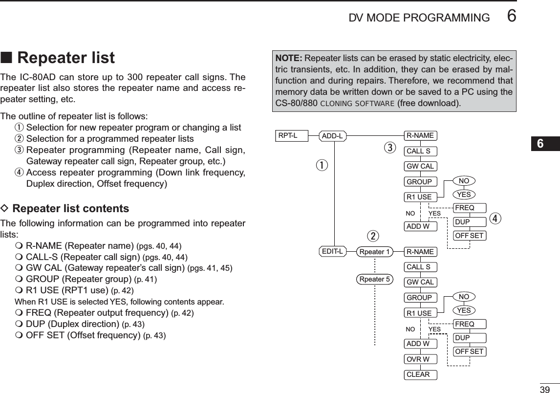
![406DV MODE PROGRAMMINGNRepeater list programmingD New repeater list programmingq Enter “ADD-L” in RPT-L menu.MENU ¶ RPT-L ¶ADD-L (Push [MENU ]), (push [](2)/[](8), then push [ ](5).)• “R-NAME” appears.Repeater name programming (R-NAME)w Push [](5) to enter the repeater name programming state. See p. 44 for repeater name programming details.• Repeater name programming screen is displayed.e Program the repeater name, then push [ ](5) to exit the state.• Push [](2)/[](8) to select the desired character, number, symbol or space. • Push [](6)/[](4) to move the cursor right or left, respectively. r Push [](2) or [](8) to select the next content (repeater call sign programming).Repeater call sign programming (CALL S)t Push [](5) to enter the repeater call sign programming state. See p. 44 for repeater call sign programming de-tails.• Repeater call sign programming screen is displayed.y Program the repeater call sign, then push [ ](5) to exit the state.• Push [](2)/[](8) to select the desired character, number, symbol (‘/’only) or space. • Push [](6)/[](4) to move the cursor right or left, respectively. u Push [](2) or [](8) to select the next content (gateway repeater call sign programming). CONVENIENT!After you program the repeater call sign, you can skip the other programming and store the list.±Push and hold [S.MW](M/CALL) for 1 sec. to enter mem-ory write state, then push [](5) to store the list.](https://usermanual.wiki/ICOM-orporated/315500.User-Manual-1/User-Guide-1070560-Page-48.png)
 to enter the gateway repeater call sign pro-gramming state. See p. 45 for gateway repeater call sign programming details.• Gateway repeater call sign programming screen is displayed.• Programmed repeater call sign is displayed and the 8th digit is automatically added or replaced to “G.”o When the programmed repeater has gateway capability, push [](5) to exit gateway repeater setting and skip to !2. Or when the programmed repeater has a different repeater for gateway communication, follow the next step !0.• When the repeater does not have a gateway repeater, follow the next step !0, too.!0 Program the other gateway repeater call sign, then push [](5) to exit the state.• Push [](2)/[](8) to select the desired character, number, symbol (‘/’only) or space. • Push [](6)/[](4) to move the cursor right or left, respectively. • Up to an 8 digit call sign can be set, but 8th digit must be set to “G.”• When the repeater does not have a gateway repeater, push and hold [CLR](1) for 1 sec. to erase all characters.!1 Push [](2) or [](8) to select the next content (repeater group programming).Repeater group programming (GROUP)!2 Push [](5) to enter the repeater group programming state.• Repeater group programming screen is displayed.• Selected group number appears and group indicator blinks.!3 Push [](2) or [](8) to select the desired repeater group.• Selected group number appears and group indicator blinks.!4 Push [ ](5) to set the repeater group and exit the state.!5 Push [](2) or [](8) to select the next content (access repeater setting).Push [](2) or [](8) (or rotate [DIAL]) to se-lect the desired character, number, symbol or space.Push [](6) to move the cursor right; push [](4) to move the cursor left. Push [CLR](1) to erase the selected character, or push and hold [CLR](1) for 1 sec. to erase all characters following the cursor.](https://usermanual.wiki/ICOM-orporated/315500.User-Manual-1/User-Guide-1070560-Page-49.png)
 to enter the access repeater programming state.• Access repeater programming screen is displayed.!7 Push [](2) or [](8) to select “YES” or “NO.”• When “NO” is selected, the repeater can be selected as the link repeater (RPT2) only in DR mode.• When “YES” is selected, the repeater can be selected as the ac-cess repeater (RPT1) and link repeater (RPT2) in DR mode.!8 Push [ ](5) to exit the state.±When “NO” is selected at step !7, skip to step #1.±When “YES” is selected at step !7, push [](2) or [](8)to select the access repeater (RPT1) programming. Follow the next step !9 to program the repeater.Frequency programming (FREQ)This content appears when R1 USE is selected YES.!9 Push [](5) to enter the frequency programming state.• Frequency programming screen is displayed.@0 Push [](2) or [](8) to select the frequency band.• The selected number blinks at 1st digit.• Push [](6) to move the cursor right; push [](4) to move the cursor left. • Push and hold [CLR](1) for 1 sec. to clear the displayed fre-quency.@1 Repeat step @0 until the repeater frequency is set.@2 Push [ ](5) to set the frequency and exit the state.@3 Push [](2) or [](8) to select the next content (duplex direction programming).](https://usermanual.wiki/ICOM-orporated/315500.User-Manual-1/User-Guide-1070560-Page-50.png)
 to enter the duplex direction setting state.• Duplex direction setting screen is displayed.@5 Push [](2) or [](8) to select the duplex direction.@6 Push [ ](5) to set the duplex direction and exit the state.@7 Push [](2) or [](8) to select the next content (offset frequency programming).Offset frequency programming (OFF SET)This content appears when R1 USE is selected YES.@8 Push [](5) to enter the offset frequency programming state.• Offset frequency programming screen is displayed.@9 Push [](2) or [](8) to select the offset frequency.• The selected number blinks.• Push [](6) to move the cursor right; push [](4) to move the cursor left. • Push and hold [CLR](1) for 1 sec. to clear the displayed fre-quency.#0 Push [ ](5) to set the offset frequency and exit the state.Storing the repeater list (ADD W)#1 Push [](2) or [](8) to select the store operation.#2 Push [](5) to enter storing state.• “ADD W OK?” appears.#3 Push [ ](5) again to store the list.](https://usermanual.wiki/ICOM-orporated/315500.User-Manual-1/User-Guide-1070560-Page-51.png)
 to enter the repeater name programming state.• Repeater name programming screen is displayed.• The 1st digit blinks.w Push [](2) or [](8) to select the desired character, num-ber, symbol or space.• The selected character blinks.• Push [](6) to move the cursor right; push [](4) to move the cursor left. • Push [CLR](1) to erase the selected character, or push and hold [CLR](1) for 1 sec. to erase all characters following the cursor.e Repeat step w until the desired repeater name is pro-grammed.• Up to an 8 digit name can be set.r Push [ ](5) to program the repeater name and exit the state. Repeater call sign programming (CALL S)q Push [ ](5) to enter the repeater call sign programming state.• Repeater call sign programming screen is displayed.• The 1st digit blinks.w Push [](2) or [](8) to select the desired character, num-ber or symbol (‘/’ only).• The selected character blinks.• Push [](6) to move the cursor right; push [](4) to move the cursor left. • Push [CLR](1) to erase the selected character, or push and hold [CLR](1) for 1 sec. to erase all characters following the cursor.e Repeat step w until the desired repeater call sign is pro-grammed.• Up to an 8 digit call sign can be set.r Push [ ](5) to program the repeater call sign and exit the state.](https://usermanual.wiki/ICOM-orporated/315500.User-Manual-1/User-Guide-1070560-Page-52.png)
 to enter the gateway repeater call sign pro-gramming.• Gateway repeater call sign programming screen is displayed.• Programmed repeater call sign is displayed, then the 1st char-acter blinks.• The 8th digit is automatically added or replaced to “G.”w Push [](2) or [](8) to select the desired character, num-ber, symbol (‘/’ only) or space.• The selected character blinks.• Push [](6) to move the cursor right; push [](4) to move the cursor left. • Push [CLR](1) to erase the selected character, or push and hold [CLR](1) for 1 sec. to erase all characters following the cursor.e Repeat step w until the desired repeater call sign is pro-grammed.• Up to an 8 digit call sign can be set, but 8th digit must be set to “G.”r Push [ ](5) to program the gateway repeater call sign and exit the state.NChanging a repeater listYou can edit the contents of a repeater list to correct errors or added information.q Enter “EDIT-L” in RPT-L menu.MENU ¶ RPT-L ¶EDIT-L (Push [MENU ]), (Push [](2)/[](8), then push [ ](5).)• Programmed repeater name appears.SKIP indicatorSKIP indicator shows the selected repeater can not be usedfor access repeater (RPT1) in DR mode as follow reasons. • “R1 USE” is set to “NO”• Either “FREQ” (frequency) or “DUP” (duplex direction) has not been programmedPush and hold for 1 sec. to select SKIP indicator ON and OFF when both of “FREQ” and “DUP” have been programmed.w Push and hold [BAND] for 1 sec. to enter group selection, rotate [DIAL] to select the desired group (0–9), then push [BAND].e Push [](2) or [](8) to select the desired repeater list to be changed.](https://usermanual.wiki/ICOM-orporated/315500.User-Manual-1/User-Guide-1070560-Page-53.png)
 to enter the list.t Push [](2) or [](8) to select the content to be changed, then push [ ](5) to enter the content and reprogram the content (see pages 40–43 for new repeater list program-ming details).y After programming is finished, push [](2) or [](8) to select “ADD W” or “OVR W,” then push [](5).When “ADD W” is selected;• “ADD W OK?” appears.When “OVR W” is selected;• “OVR W OK?” appears.y Push [ ](5) again to store the list.NClearing a repeater listContents of programmed list can be cleared (erased).q Enter “EDIT-L” in RPT-L menu.MENU ¶ RPT-L ¶EDIT-L (Push [MENU ]), (Push [](2)/[](8), then push [ ](5).)• Programmed repeater name appears.w Push [](2) or [](8) to select the desired repeater list to be erased.• Push and hold [BAND] for 1 sec. to enter group selection, rotate [DIAL] to select the desired group (0–9) then push [BAND].e Push [ ](5) to enter the list.r Push [](2) or [](8) to select “CLEAR,” then push [ ](5).• “CLEAR OK?” appears.t Push [ ](5) again to clear the list.](https://usermanual.wiki/ICOM-orporated/315500.User-Manual-1/User-Guide-1070560-Page-54.png)
![477DV MODE OPERATION12345678910111213141516171819N Digital mode operationThe IC-80AD can be operated in digital voice mode and low-speed data operation for both transmit and receive. It can also be connected to a GPS receiver (compatible with an RS-232 output/NMEA format/4800 bps/9600 bps) to transmit/receive position data.N Current call sign settingSet the current call sign for DV operation as follows.qEnter “CALL-S” in MENU screen.MENU ¶CALL-S (Push [MENU ]), (Push [](2)/[](8), then push [ ](5).)• Call sign screen is displayed.w Push [](2) or [](8) to select the desired call sign group, “UR,” RPT1,” “RPT2” or “MY,” then push [](5).• Current call sign is displayed.Quick entryPush and hold [CS](9) for 1 sec. to enter the current call sign mode. See next page for details.• Call sign groupUR : Station call signs (U01–U60), “CQCQCQ” (U--) or repeater CQ* (R-L) can be selected.* ‘/’ plus repeater call sign (R-L), ‘/’ stands for “CQCQCQ”RPT1 : “NOTUSE”* (R--) or repeater call signs (R-L) can be selected.* Direct communication (NOT USE repeater)RPT2 : “NOTUSE”* (R--) or repeater call signs (R-L) can be selected.* Direct communication or using area repeater only (NOT USE link repeater)MY : My call signs (MY1–MY6) can be selected.e Push [](2) or [](8) to select the desired call sign.Or push [](6) to enter the current call sign programming state (pgs. 36–38).• When “UR,” “RPT1” or “RPT2” is selected at step w, push [BAND] several times to select the repeater call sign groups.• When “RPT1” or “RPT2” is selected at step w, push and hold [CS](9) for 1 sec. to toggle the call sign and repeater name in-dications.r Push [ ](5) to set the selected call sign to the current call sign and exit the state.t Repeat steps w to r to set the other current call sign.yPush [MENU ] to return to frequency indication.](https://usermanual.wiki/ICOM-orporated/315500.User-Manual-1/User-Guide-1070560-Page-55.png)
 for 1 sec. to enter the current call sign mode.• Current UR (your) call sign is displayed.Appears momentarilyw Push [](2) or [](8) to select and confirm the other cur-rent call sign.• (“UR”), “R1,” “R2” and “MY” appears in sequence.• When “R1” or “R2” is selected, push and hold [CS](9) for 1 sec. to toggle the call sign and repeater name indications.When changing the call signq Push [ ](5) to enter the call sign selection mode.w Push [](2) or [](8) to select the desired call sign, then push [](5).• When “UR,” “R1” or “R2” is selected, push [BAND] several times to select the repeater call sign groups.e Push [CS](9) again to return to frequency indication.N Receiving a D-STAR repeaterWhen the IC-80AD receives a signal from a D-STAR re-peater, it receives four call sign: caller’s call sign, called call sign, repeater call sign 1 (the repeater that caller accessed), and repeater call sign 2 (the liked repeater). You can copy the received call signs to current call signs, and you can also reply to a call.Station A Station BRepeater449.700 MHz444.700 MHz 444.700 MHz449.700 MHzUplinkDownlink(transmitting freq.)(receiving freq.)• Presettingq Set the desired repeater frequency. (p. 23)• Select output power, if desired. (p. 27)w Set the shift direction of the transmit frequency. (DUP– or DUP; see p. 31 for details.)• When the auto repeater function is in use (U.S.A. and Korean versions only), this selection is not necessary. (p. 32)eSelect DV mode. (p. 25)r When signal is received, display indicates received call sign. See next page for information about received call signs.487DV MODE OPERATION](https://usermanual.wiki/ICOM-orporated/315500.User-Manual-1/User-Guide-1070560-Page-56.png)
![497DV MODE OPERATION71234568910111213141516171819N Received call signWhen a call is received in DV mode, the calling station and the repeater call signs being used can be stored into the re-ceived call record. The stored call signs are viewable in the following manner. Up to 20 calls can be recorded.D Desired call record indicationqEnter RX call sign set mode.MENU ¶RX-CAL (Push [MENU ]), (Push [](2)/[](8), then push [ ](5).)• RX call sign screen is displayed.w Push [](2) or [](8) to select the desired record chan-nel.e To confirm the received call, push [ ](5) several times to select the desired call sign from CALLER, / (CALLER’s note), CALLED, RXRPT1 and RXRPT2.CALLER : The station call sign that made a call./: 4 character note with call sign that made a call.CALLED : The station call sign called by the caller.RXRPT1 : The repeater call sign used by the caller station.RXRPT2 : The repeater call sign linked from RXRPT1.rPush [MENU ] to return to frequency indication.For your informationWhen receiving a call, the received station call sign is auto-matically displayed and scrolled in sequence in the frequency display.This can be turned OFF in DISP set mode. (p.132)PushC NOTE: When a call is received in DV mode when the power save function is activated, the call sign may not be received correctly. This is normal, not a malfunction, because the call sign information cannot be detected during power save.Turn the power save function OFF (p. 123) if you want to receive a call sign correctly even in stand-by operation.](https://usermanual.wiki/ICOM-orporated/315500.User-Manual-1/User-Guide-1070560-Page-57.png)
 for 1 sec.Or, while pushing and holding [RX©CS](8), rotate [DIAL]to select the desired call sign record.The received call sign is displayedwhile pushing and holding with rotating .• Set your own call sign (MY) in advance. (pgs. 36, 47, 48)• The call sign in “CALLER” is stored as “UR,” “RXRPT1” is stored as “R2” and “RXRPT2” is stored as “R1.”• Error beeps sound when a call sign is received incorrectly, and no call sign is set in this case.w Push [PTT] to transmit; release to receive.Important!Setting call signs with the “One-touch reply using the call record” operation as at left are for temporary operation only. Therefore, the set call signs will be over-written when another call record is used to set call signs.• Never saved into a call sign memory.If you want to save the set call signs, see “Copying the call record contents into call sign memory” (p. 51) for details.For your informationWhen a call specifying your call sign is received, the call signs of the calling station and the repeater it is using can be automatically used for operation.• When “CALL W (RX call sign auto write)” (p. 131) is set to “AUTO,” the station call sign in “CALLER” is set to “UR” au-tomatically.• When “RPT W (Repeater call sign auto write)” (p. 131) is set to “AUTO,” the repeater call sign in “RXRPT1” is stored as “R2” and “RXRPT2” is stored as “R1” automatically.](https://usermanual.wiki/ICOM-orporated/315500.User-Manual-1/User-Guide-1070560-Page-58.png)
![517DV MODE OPERATION12345678910111213141516171819N Copying the call signD Copying the call sign memory contentsThis function is convenient when or modifying a part of the current call sign.q During DV mode operation, enter call sign menu.MENU ¶CALL-S (Push [MENU ]), (Push [](2)/[](8), then push [ ](5).)w Push [](2) or [](8) to select “UR,” then push [ ](5).e Push [](2) or [](8) to select the desired call sign chan-nel to be copied.• U01–U60 are available.• When “AUTO” is set to “EDIT R” itemrPush [](6) to select the call sign programming mode.• The 1st digit of the selected call sign blinks.Blank channel is selectedautomatically.t Modify the selected call sign as described in “Station call sign programming” (p. 37).y Push [](5) to store the modified call sign into the selected blank channel.NOTE: Make sure that the “EDIT R (EDIT RECORD)” item in DV set mode is set to “AUTO” or “SEL” in advance. (p. 132)NOTE: The message “FULL” is displayed when no blank channel is available in station call sign memory.In this case, select the desired call sign channel number as described in step u is set to “• When “SEL” is set to “EDIT R” item below.• When “SEL” is set to “EDIT R” itemrPush [](6) to select the call sign programming mode.• The 1st digit of the selected call sign blinks.t Modify the selected call sign as described in “Station call sign programming” (p. 37).y Push [ ](5).• Call sign channel number blinks.Call sign channel numberblinks.u Push [](2) or [](8) to select the desired call sign chan-nel to store.i Push [ ](5) to store the modified call sign into the selected channel.](https://usermanual.wiki/ICOM-orporated/315500.User-Manual-1/User-Guide-1070560-Page-59.png)
![527DV MODE OPERATIONThis is a way to copy the call record contents (“CALLER,” “RXRPT1” and “RXRPT2”) into call sign memory (“UR,” “R1” and “R2”) at the same time or individually. qEnter RX-CS (RX call sign) mode.MENU ¶RX-CS (Push [MENU ]), (Push [](2)/[](8), then push [ ](5).)• RX call sign screen is displayed.w Push [](2) or [](8) to select the desired record chan-nel.e Push [](5) several times to select the desired call sign from CALLER, / (CALLER’s note), CALLED, RXRPT1 and RXRPT2.CALLER : The station call sign that made a call./: 4-character note with call sign that made a call.CALLED : The station call sign called by the caller.RXRPT1 : The repeater call sign used by the caller station.RXRPT2 : The repeater call sign linked from RXRPT1.rPush [](6) to enter copy select mode.• Copy select screen is displayed.t Push [](2) or [](8) to select the desired call sign to be copied from “C ALL,” “C UR01”–“C UR60,” “C R-L” and “CLEAR.”• “C ALL” selection won’t appear when either station call sign memory or repeater list has no blank channel.y Push [](5) to copy the selected record’s contents into the appropriate call sign memory or repeater lists.C ALL : Copy the caller call sign in “CALLER” to “UR” (sta-tion call sign memory) and the repeater call sign in “RXRPT1” / “RXRPT2” to the repeater lists. This selection won’t appear when either station call sign memory or repeater list has no blank channel.C UR01– : C UR60 : Copy the caller call sign in “CALLER” to “UR” (sta-tion call sign memory). This selection appears when entering the copy select mode (step r) from “CALLER” only.C R-L : Copy the repeater call sign in “RXRPT1” / “RXRPT2” to the repeater lists. This selection appears when entering the copy select mode (step r) from “RXRPT1” or “RXRPT2” only.CLEAR : Clear (erase) the selected call record contents.uPush [MENU ] to return to frequency indication.D Copying the call record contents into call sign memory](https://usermanual.wiki/ICOM-orporated/315500.User-Manual-1/User-Guide-1070560-Page-60.png)