ICOM orporated 315500 VHF/UHF Amateur Transceiver User Manual 3
ICOM Incorporated VHF/UHF Amateur Transceiver 3
UserManual.wiki
>
ICOM orporated
>
315500 User Manual
>
User Manual 3
Contents
1.
User Manual 1
2.
User Manual 2
3.
User Manual 3
User Manual 3
Navigation menu
Upload a User Manual
Namespaces
Wiki Guide
HTML
PDF
Info
Views
User Manual
Discussion / Help
Navigation
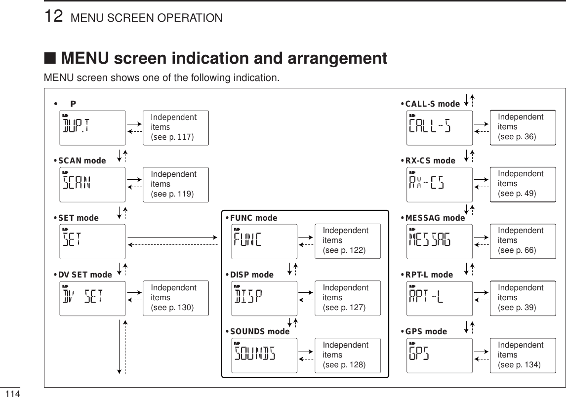
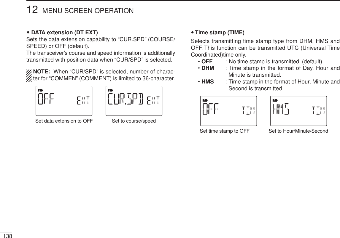
![11312MENU SCREEN OPERATION12345678910111213141516171819N GeneralMENU screen is used for programming infrequently changed values or conditions of functions.D Entering MENU screen and operatione.g.) Set “KEY B (Key-touch beep)” to OFF.qPush [MENU ] to enter MENU screen.•“DUP.T,” “SCAN,” “SET,” “DV SET,” “CALL-S,” “RX-CS,” “MES-SAG,” “RPT-L” or “GPS” appears.w Push [](2) or [](8) (or rotate [DIAL]) to select the de-sired menu group, then push [](5) (or [](6)).e When “SET” is selected, push [](2) or [](8) (or rotate [DIAL]) to select the desired function group, then push [](5) (or [](6)).r Push [](2) or [](8) to select the desired item, then push [](5) (or [](6)).t Push [](2) or [](8) (or rotate [DIAL]) to select the de-sired value or condition, then push [](5) (or [](4)) to return to the setting item selection mode.y Push [MENU ] (or [V/MHz]) to return to frequency indi-cation, repeat steps w to r to set another items.[DIAL]Enter menu screenPush to select “SET.”Push . Push .PL Set “KEY B (Key-touch beep)” to OFF.Push . Push .Push to select “KEY B.” Push to select “OFF,” then push .Push to select “SOUNDS.”](https://usermanual.wiki/ICOM-orporated/315500.User-Manual-3/User-Guide-1070571-Page-1.png)
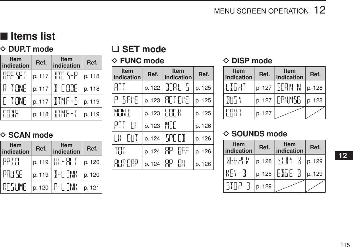

![11912MENU SCREEN OPERATION12345678910111213141516171819D DTMF speed (DTMF-S)Select the desired DTMF transmission speed from 100 msec, 200 msec, 300 msec, 500 msec.• 100 : 100-msec. interval; 5.0 characters per second (default)• 200 : 200-msec. interval; 2.5 characters per second• 300 : 300-msec. interval; 1.6 characters per second• 500 : 500-msec. interval; 1.0 character per secondD DTMF TX key (DTMF-T)Selects DTMF transmitting code when pushing and holding [PTT], then pushing one of the keypad buttons.• KEY : [1]–[9], [0], [A], [B], [C], [D], [E](1) or [F](#) DTMF tones are transmitted when the key is pressed. (default)• DTMF-M : The DTMF memory contents Ch01–Ch10 and transmitted.N Scan items (SCAN)D Priority watch (PRIO)Activates priority watch or priority watch with alert (Bell).• OFF : The priority watch is turned OFF. (default)• ON : The transceiver checks the memory channel fre-quency every 5 sec.• BELL : The transceiver checks the memory channel frequency every 5 sec. You can be alerted with beeps and blinking “S.”D Scan pause timer (PAUSE)Selects the scan pause time. When receiving signals, the scan pauses according to the scan pause timer.• 2–20 SEC : Scan pauses for 2–20 sec. while receiving a signal in 2 sec. steps. (default: 10 sec.)• HOLD : Scan pauses on a received signal until it dis-appears.](https://usermanual.wiki/ICOM-orporated/315500.User-Manual-3/User-Guide-1070571-Page-7.png)
![D Scan resume timer (RESUME)Selects the scan resume time from a pause after the received signal disappears.• 0 SEC : Scan resumes immediately after the received signal disappears.• 1–5 SEC: Scan pauses 1–5 sec. after the received signal disappears. (default: 2 sec.)• HOLD : Scan remains paused on the received signal according to the scan pause timer even if it dis-appears. Rotate [DIAL] to resume manually.Scan resume timer must be set shorter than scan pause timer (previous item), otherwise this timer cannot be acti-vated.U.S.A. version onlyD Weather alert (WX-ALT)Turns weather alert function ON and OFF. (p. 153)(default: OFF)D Memory bank link function (B-LINK)Sets the memory bank link function ON (default) and OFF. The link function provides continuous bank scan, scanning all channels in the selected banks during bank scan.• Bank link settingqPush [](2) or [](8) to select the bank that you want to change the link setting.wPush [ ](5) to enter bank setting.ePush [](2) or [](8) to select the setting. rPush [](5) to set and return to the BANK selection screen.tPush [](2) or [](8) to select next bank and repeat steps w to r, or push [MENU ]to exit MENU screen operation.12012 MENU SCREEN OPERATION](https://usermanual.wiki/ICOM-orporated/315500.User-Manual-3/User-Guide-1070571-Page-8.png)
 or [](8) to select the program scan link number that you want to change.wPush [ ](5) to enter the program scan link setting.ePush [](2) or [](8) several times to select the setting “ADD” or “CLEAR.”• When “ADD” is selected, only no-linked program scans are dis-played. When “CLEAR” is selected, only linked program scans are displayed. rPush [ ](5), then push [](2) or [](8) to select the desired program scan.tPush [ ](5) to set the program scan link setting.yRepeat steps r and t to add or clear the program scan to/from the link, or push [MENU ]to exit MENU screen operation.](https://usermanual.wiki/ICOM-orporated/315500.User-Manual-3/User-Guide-1070571-Page-9.png)
 or [](8) to select the program scan link number that you want to program the name.wPush [ ](5) to enter the program scan link setting.ePush [](2) or [](8) several times to select “NAME.”ePush [](5) to enter the program scan link setting.r Push [](2) or [](8) to select the desired character, number, symbol or space; push [](6) or [](4) to move the cursor right or left, respectively.t Push [](5) to program the repeater name and exit the state.y Push [MENU ]to exit MENU screen operation.N Set mode items (SET) Function set mode items (FUNC)D Attenuator (ATT)The attenuator prevents distortion of a desired signal by very strong RF signals near the desired frequency or when very strong electric fields, such as from a broadcasting station, are present at your location.Select the attenuator function ON and OFF (default).12212 MENU SCREEN OPERATION](https://usermanual.wiki/ICOM-orporated/315500.User-Manual-3/User-Guide-1070571-Page-10.png)
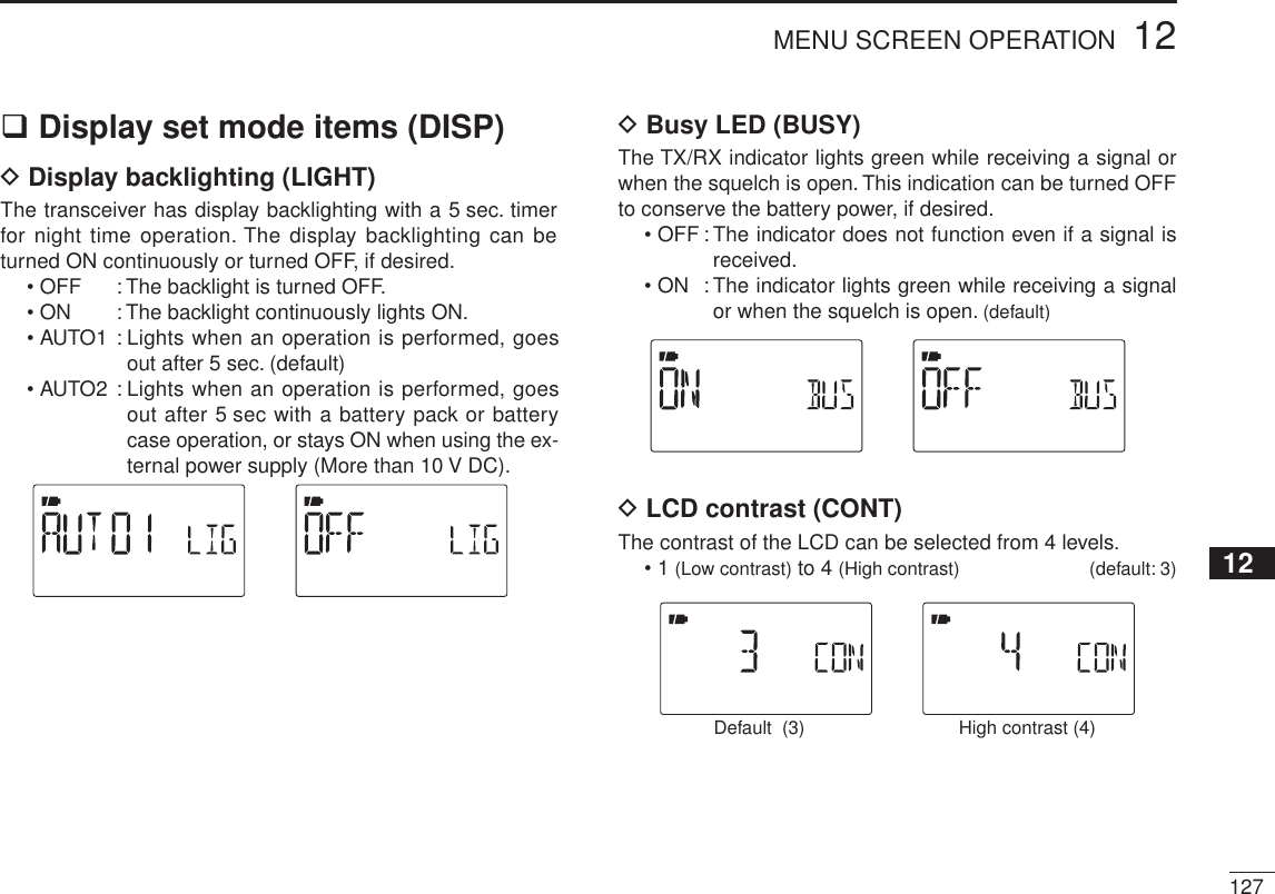
![12312MENU SCREEN OPERATION12345678910111213141516171819D Power save (P SAVE)The power save function reduces the current drain to con-serve battery power. This power save function can be turned OFF, if desired, by turning power ON and OFF. • “AUTO1” selects “1:4” duty ratio when receiving no signal for 5 sec., then “1:8” 60 sec. after that.• “AUTO2” suppresses the consumption of the battery by stopping the operation of a digital block of the DV mode in addition to the op-eration of Auto1. NOTE: Power save function is disable when using the ex-ternal power supply (More than 10 V DC) or if the Auto re-play function is set to ON (p. 130).D Monitor key action (MONI)The monitor key, [SQL], can be set as a ‘sticky’ key. When set to the sticky condition, each push of [SQL] toggles the moni-tor function ON and OFF.• PUSH: Pushing and holding [SQL] to monitor the fre-quency. (default)• HOLD : Push [SQL] momentarily to monitor the frequency and push momentarily again to cancel it.DPTT lock (PTT LK)PTT lock (PTT LK)Turns the PTT lock function ON and OFF.This function inhibits transmission with [PTT] is inhib-ited when ON is selected to prevent accidental trans-mission, etc. (default: OFF)](https://usermanual.wiki/ICOM-orporated/315500.User-Manual-3/User-Guide-1070571-Page-11.png)

![12512MENU SCREEN OPERATION12345678910111213141516171819D Dial speed acceleration (DIAL S)The dial speed acceleration automatically speeds up the tun-ing dial speed when rotating [DIAL] rapidly.• OFF : The dial speed acceleration is turned OFF.• ON : The dial speed acceleration is tuned ON. (default)D Active band (ACTIVE)Allows continuous frequency selection of the operating fre-quency across all bands.• SINGLE : A single operating frequency can be se-lected within the current band. Push [BAND] for band selection in this case.• ALL : The operating frequency can be selected continuously. (default)D Key lock type (LOCK)While the key lock function is ON, [PWR], [PTT], [SQL],[VOL] and [MENU](Lock function only) can still be accessed. Accessible keys can be set to 1 of 4 groups.• NORMAL: [PWR], [PTT], [SQL], [VOL] and [MENU] (Lock function only) accessible. (default)• NO SQL : [PWR],[PTT],[VOL] and [MENU] (Lock func-tion only) are accessible.• NO VOL : [PWR],[PTT],[SQL] and [MENU] (Lock func-tion only) are accessible.• ALL : [PWR],[PTT] and [MENU] (Lock function only)are accessible.](https://usermanual.wiki/ICOM-orporated/315500.User-Manual-3/User-Guide-1070571-Page-13.png)
![D Microphone simple mode (MIC)Microphone simple mode is used to change the function as-signments for keys on the optional HM-75A REMOTE CONTROLSPEAKER-MICROPHONE. (p. 162)• SIMPLE• NORM-1 (default)• NORM-2D DATA speed (SPEED)Selects the data speed of [DATA] jack from 4800 bps and 9600 bps (default) for GPS receiving, etc.When 4800 bps is selectedWhen 9600 bps is selectedD Auto power OFF (AP OFF)The transceiver can be set to automatically turn OFF after a specified time period with a beep when no key operations are performed.30 min., 60 min, 90 min, 120 min and OFF (default) can be specified. The specified time period is retained even when the transceiver is turned OFF by the auto power OFF function. To cancel the function, select “OFF” in this item.D Auto power ON (AP ON)Auto power ON function turns the transceiver power ON auto-matically after passing the set time period from power OFF.Select the desired time period within 30 minutes to 24 hours in 30 minutes steps and OFF. (default: OFF)12612 MENU SCREEN OPERATION](https://usermanual.wiki/ICOM-orporated/315500.User-Manual-3/User-Guide-1070571-Page-14.png)

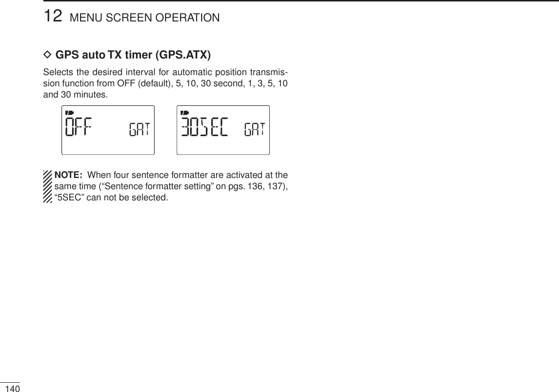
![12912MENU SCREEN OPERATION12345678910111213141516171819D Scan stop beep (STOP B)Turns the scan stop beep function ON or OFF. (default: OFF)Scan stop beep ON Scan stop beep OFFD Standby beep (STBY B)Turns the beep emission capability ON and OFF when the communicating station finishes transmitting or the receive signal disappears while in the digital mode operation.(default: ON)Stand by beep ON Stand by beep OFFDBand edge beep (EDGE B)Turns the beep emission capability ON and OFF when the frequency is changed over the band edge by rotating [DIAL].(default: ON)Band edge beep ON Band edge beep OFF](https://usermanual.wiki/ICOM-orporated/315500.User-Manual-3/User-Guide-1070571-Page-17.png)
![NDV set mode items (DV SET)D Auto reply (REPLY)This function replies to an individual station call even you are away from the transceiver.After a manual transmission (pushing [PTT]), the Auto Reply setting returns to OFF automatically.• OFF : No reply is performed even if a call is received. (default)• ON : Sets the caller's call sign and replies to the call with the programmed own call sign.NOTE: When “ON” is set in the auto reply function, the power save function (p. 123) stop functioning automatically to receive call sign signal properly.D DV data TX (DATATX)During low-speed data operation, auto data transmission function is available. This function transmits when data has been input from PC via the [DATA] jack. (default: PTT)• PTT : Data from [DATA] transmits when [PTT] is pushed. (default)• AUTO : Data from [DATA] transmits automatically.D Digital monitor (D MONI)Sets the desired monitoring mode during digital mode opera-tion from “Auto,” “Digital” and “Analog.”• AUTO : The transceiver sets monitoring mode to FM and DV according to the received signal. (default)• DIGI : Monitors in DV mode.• ANALOG : Monitors in FM mode.13012 MENU SCREEN OPERATION](https://usermanual.wiki/ICOM-orporated/315500.User-Manual-3/User-Guide-1070571-Page-18.png)

![13512MENU SCREEN OPERATION12345678910111213141516171819 UTC offset (UTC.OFF)Sets time difference from UTC (Universal Time Coordinated)within –12:00 to +12:00 range in 5 min. steps. (default: 0:00)Set to +12:00 hourSet to –12:00 hour GPS indication (INDIC)Sets the GPS indicator ON and OFF. (default : ON)• OFF : “G” indicator does not appear.• ON : “G” indicator appears on the display when a GPS receiver is connected and a valid position data is received; blinks when an invalid data is received.GPS indication OFFGPS indication ONGPS data out (GPS.OUT)Sets the GPS data received from a connected optional GPS microphone, HM-189GPS to output from [DATA] jack.• OFF : Transceiver does not output the GPS data. (default)• ON : Transceiver outputs the GPS data from [DATA] jack.Data output is OFFData output is ON](https://usermanual.wiki/ICOM-orporated/315500.User-Manual-3/User-Guide-1070571-Page-23.png)
 to enter the sentence formatter selection.w Push [](2) or [](8) to select the desired sentence formatter.• RMC, GGA, GLL, GSA, VTG and GSV are selectable.GGA sentenceRMC sentencee Push [ ](5) to enter the desired sentence formatter selection.r Push [](2) or [](8) to select the setting. • See right above for setting details.RMC sentence: ONRMC sentence: OFFt Push [ ](5) to set ON/OFF.y Push [](2) or [](8) to select next sentence and repeat steps w to t, or push [MENU ] to return to frequency indication.• Only four sentence formatters can be activated at same time.13612 MENU SCREEN OPERATION](https://usermanual.wiki/ICOM-orporated/315500.User-Manual-3/User-Guide-1070571-Page-24.png)
. This set mode is available to set unproto address, data extension, time stamp, GPS-A symbol and comment. Unproto Address (UNPROT)56 characters address can be entered for unproto address.q Push [ ](5) to enter the unproto address edit mode.w Push [](2) or [](8) to select the desired character.• The selected character blinks.• Push [](6) to move the cursor right; push [](4) to move the cursor left. • Push [CLR](1) to erase the selected character, or push and hold [CLR](1) for 1 sec. to erase all characters following the cursor.e Repeat step w until the desired unproto address is pro-grammed.r Push [](5) to program the unproto address and exit theunproto address edit mode.t Push [](4) to return to GPS-A set mode screen.](https://usermanual.wiki/ICOM-orporated/315500.User-Manual-3/User-Guide-1070571-Page-25.png)
 to begin the programming.w Push [](2) or [](8) to select the 1st character from “\” and “/.”e Push [](6) to select the 2nd digit.r Push [](2) or [](8) to select the 2nd digit character.t Push [](5) to program the symbol code, then exit pro-gramming.y Push [](4) to return to GPS-A set mode screen.When “OTHER” is selected, check the symbol codes of APRS® and set it correctly.Car is selectedHelicopter is selectedComment (COMMEN)Program up to a 43-character* comment. The programmed comment is transmitted with the GPS position data.*36-character comment can only be programmed when “CUR/SPD” (COURSE/SPEED) is selected in DT EXT (Data extension).q Push [](5) twice to enter the programming.w Push [](2) or [](8) to select the desired character.• The selected character blinks.• Push [](6) to move the cursor right; push [](4) to move the cursor left. • Push [CLR](1) to erase the selected character, or push and hold [CLR](1) for 1 sec. to erase all characters following the cursor.e Repeat step w until the desired comment is programmed.r Push [](5) to program the comment and exit comment programming.t Push [](4) to return to GPS-A set mode screen.](https://usermanual.wiki/ICOM-orporated/315500.User-Manual-3/User-Guide-1070571-Page-27.png)
 for 1 sec. to enter DTMF memory.DTMF memory channelBlank channel indicationw Push [](2) or [](8) to select the desired DTMF memory channel.• “T-CALL” appears when a 1750 Hz tone burst signal is selected. (p. 33)• Previously programmed DTMF code is displayed if pro-grammed.ePush [](6) to enter programming mode.The cursor is blinking whenentering programming mode.rPush the desired keys to input the characters.•[0]–[9] input “0”–“9,” [A](V/MHz) inputs “A,” [B](M/CALL) inputs “B,” [C](DR) inputs “C,” [D]() inputs “D,” [#](.) inputs “E (#)” and [1](BAND) inputs “1(F).”• Up to 24 digits can be programmed.Next display appears after6th digit has been input.tRepeat step r until the desired code is input.y Push [MENU ]to program the DTMF code and exit programming mode.• Entering 24th digit automatically exits the programming mode.uPush [V/MHz] to exit DTMF memory.](https://usermanual.wiki/ICOM-orporated/315500.User-Manual-3/User-Guide-1070571-Page-29.png)
![14213 OTHER FUNCTIONSN Transmitting a DTMF codeDTransmitting from DTMF memoryThe selected DTMF code is transmitted at each push of the [SQL] switch while transmitting.The transmitting speed at which DTMF memories send individual DTMF characters can be set in “DTMF-S” (DTMF SPEED) item. (p. 119)q Set the desired frequency. (p. 23)wPush and hold [DTMF.M](0) for 1 sec. to enter DTMF memory.ePush [](2) or [](8) to select the desired DTMF mem-ory channel.r PushPush [ ](5) to set the DTMF memory.t PushPush [V/MHz] to exit DTMF memory.y While pushingWhile pushing [PTT], push [SQL] to transmit the se-lected DTMF code.DTransmitting from DTMF memory in VFO modeThe selected DTMF memory can be transmitted via keypad directly while transmitting. Pushing [0]–[9], [A], [B], [C], [D], [#] or [1] to transmit DTMF memory channel (D0–D9, DA, DB, DC, DD, DE or DF) respectively.qSet the desired frequency. (p. 23)w Enter “DTMF-T” in DUP.T set mode.MENU ¶ DUP.T ¶DTMF-T (p. 119) (Push [MENU ]), (Push [](2)/[](8), then push [ ](5).)e Push [](2) or [](8) to select DTMF transmitting key (DTMF–M) as below.r Push [ ](5) (or [](4)) to return to DUP.T set mode, and push [MENU ] to return to frequency indication.t While pushing [PTT], push the desired key to transmit the selected DTMF memory.•[0]–[9], [A](V/MHz), [B](M/CALL), [C](DR), [D](), [#](.)or [1](BAND) transmits “D0”–“D9,” “DA,” “DB,” “DC,” “DD,” “DE” or “DF.”](https://usermanual.wiki/ICOM-orporated/315500.User-Manual-3/User-Guide-1070571-Page-30.png)
![14313OTHER FUNCTIONS12345678910111213141516171819DTransmitting a DTMF code directlyDTMF code can be transmitted via keypad directly while transmitting.qSet the desired frequency. (p. 23)w Enter “DTMF-T” in DUP.T set mode.MENU ¶ DUP.T ¶DTMF-T (p. 119) (Push [MENU ]), (Push [](2)/[](8), then push [ ](5).)e Push [](2) or [](8) to select DTMF transmitting key (KEY).r While pushing [PTT], push the desired keys to transmit the DTMF code.•[0]–[9] input “0”–“9,” [A](V/MHz) inputs “A,” [B](M/CALL)inputs “B,” [C](DR) inputs “C,” [D]() inputs “D,” [#](.) inputs “#” and [1](BAND) inputs “1.”DTMF code keysN Clearing a DTMF memoryAn unwanted DTMF memory can be cleared (erased).q Push and hold [DTMF.M](0) for 1 sec. to enter DTMF memory mode.w Push [](2) or [](8) to select the desired DTMF mem-ory channel to be cleared.e Push and hold [CLR](1) for 1 sec. to clear the selected DTMF memory channel.After clearing the DTMF memory.When entering DTMF programming mode.r Push [V/MHz] to exit DTMF memory.](https://usermanual.wiki/ICOM-orporated/315500.User-Manual-3/User-Guide-1070571-Page-31.png)
 for 1 sec. to enter DTMF memory mode.w Push [](2) or [](8) to select the desired DTMF memory channel.ePush [SQL] to confirm the DTMF memory contents.r Push [V/MHz] to exit DTMF memory.N Setting DTMF transfer speedThe DTMF transfer speed can be selected.q Enter “DTMF-S” in DUP.T set mode.MENU ¶ DUP.T ¶DTMF-S (p. 119) (Push [MENU ]), (Push [](2)/[](8), then push [ ](5).)w Push [](2) or [](8) to select DTMF transfer speed as below.100 : Transfer the DTMF tones at about 100 msec. per tone.200 : Transfer the DTMF tones at about 200 msec per tone.300 : Transfer the DTMF tones at about 300 msec per tone.500 : Transfer the DTMF tones at about 500 msec per tone.e Push [](5) to return to DUP.T set mode, and push [MENU ] to return to frequency indication.](https://usermanual.wiki/ICOM-orporated/315500.User-Manual-3/User-Guide-1070571-Page-32.png)
![14513OTHER FUNCTIONS12345678910111213141516171819DSubaudible (repeater) toneSome repeaters require subaudible tones to be accessed. Subaudible tones are superimposed over your normal signal and must be set in advance.DTone and DTCS squelchesThe tone squelch (CTCSS) or DTCS squelch opens only when receiving a signal containing a matching subaudible tone or DTCS code, respectively. You can silently wait for calls from group members using the same tone or code. Separate tone frequencies can be set for repeater and tone squelch/pocket beep operation.DReverse tone/DTCS squelchThe reverse tone/DTCS squelch is convenient if you want to ignore a specific signal. The transceiver mutes the squelch when a signal with the matched tone or code is received. “T SQL-R” / “DTCS-R” is displayed when the reverse tone/DTCS squelch is set.DPocket beepThese functions use subaudible tones or DTCS codes for calling and can be used as a “common pager” to inform you that someone has called while you were away from the transceiver. DSetting subaudible tones for repeater or tone squelchq Enter “R TONE or C TONE” in DUP.T set mode.MENU ¶ DUP.T ¶R TONE (p. 117) (Push [MENU ]), (Push [](2)/[](8), then push [ ](5).)MENU ¶ DUP.T ¶C TONE (p. 117)w Push [](2) or [](8) to select the desired repeater or CTCSS tone frequency.• Each operating band and each memory channel have indepen-dent settings.• See page 117 for available tone frequencies for details.e Push [ ](5) to return to DUP.T set mode, and push [MENU ] to return to frequency indication.Repeater tone setting CTCSS tone settingNTone frequency and DTCS code](https://usermanual.wiki/ICOM-orporated/315500.User-Manual-3/User-Guide-1070571-Page-33.png)
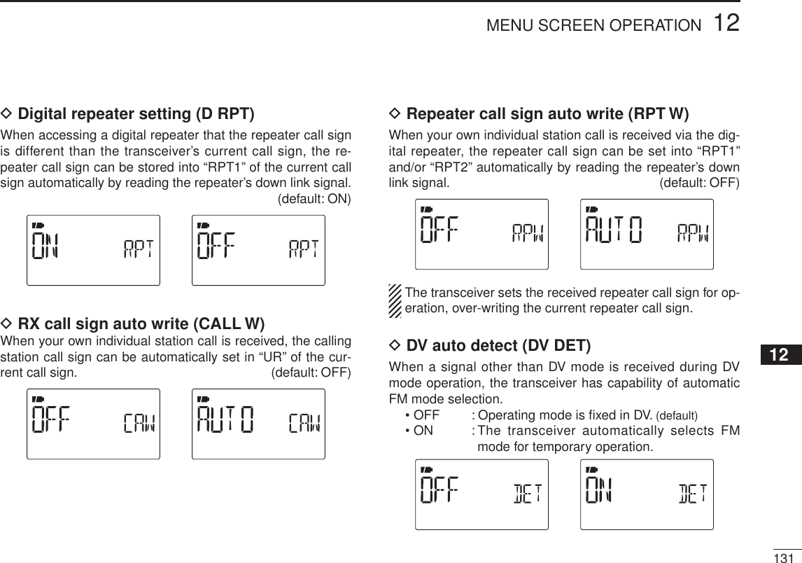
![14613 OTHER FUNCTIONSNTone frequency and DTCS code (Continued)DSetting DTCS code for DTCS squelch or beepq Enter “CODE” (DTCS CODE) in DUP.T set mode.MENU ¶ DUP.T ¶CODE (p. 118) (Push [MENU ]), (Push [](2)/[](8), then push [ ](5).)w Push [](2) or [](8) to select the desired DTCS tone code.• Each operating band and each memory channel have indepen-dent settings.• See page 118 for available DTCS codes for details.e Push [ ](5) (or [](4)) to return to DUP.T set mode, and push [MENU ] to return to frequency indication.DTCS phase can be selected in “DTCS-P” (DTCS PO-LARITY) item. (p. 118)NDigital code and digital call sign settingDSetting digital code for digital code squelch or beepq Push and hold [MODE](BAND) for 1 sec. several times to select DV mode.w Enter “D CODE” (DIGITAL CODE) in DUP.T set mode.MENU ¶ DUP.T ¶D CODE (p. 118) (Push [MENU ]), (Push [](2)/[](8), then push [ ](5).)e Push [](2) or [](8) to select the desired digital code.• Each operating band and each memory channel have indepen-dent settings.r Push [ ](5) to return to DUP.T set mode, and push [MENU ] to return to frequency indication.](https://usermanual.wiki/ICOM-orporated/315500.User-Manual-3/User-Guide-1070571-Page-34.png)
 for 1 sec. several times to select DV mode.w Enter “UR” in CALL-S set mode.MENU ¶ CALL-S ¶UR (p. 37) (Push [MENU ]), (Push [](2)/[](8), then push [ ](5).)e Push [](2) or [](8) to select the desired call sign.• Input the call sign if the desired call sign is not stored in the transceiver. See p. 37 for detail.r Push [ ](5) to specify the call sign and then push [](4)to return to CALL-S set mode.• Push [](4) to return to CALL-S set mode without storing call sign.t Push [](2) three times to select “MY” in CALL-S set mode, then push [](5) to enter “MY” setting.MENU ¶ CALL-S ¶MY (p. 36) (Push [MENU ]), (Push [](2)/[](8), then push [ ](5).)y Push [](2) or [](8) to select the desired call sign.• Input the call sign if the desired call sign is not stored in the transceiver. See p. 36 for detail.u Push [ ](5) to set call sign and push [MENU ] to re-turn to frequency indication.CAUTION!: Use digital code squelch when operating with more than 3 stations. Because the digital call sign squelch function recognizes “MY” (MY CALL SIGN) the digital call sign squelch function can be used when operating with only one station.NOTE:• The tone/DTCS code squelch opens sometimes when other stations communicate with adjacent tone frequency or DTCS code.• No audio sounds with S-meter swaying when receiving signal except my call sign on DV mode .](https://usermanual.wiki/ICOM-orporated/315500.User-Manual-3/User-Guide-1070571-Page-35.png)
 for 1 sec. several times to acti-vate the tone or DTCS squelch. (T SQL or DTCS)• Subaudible tone encoder “T,” pocket beep (tone squelch) “ST SQL,” tone squelch “T SQL,” DTCS beep “SDTCS,” DTCS squelch “DTCS,” tone squelch reverse “T SQL-R,” DTCS squelch reverse “DTCS-R” and no tone operation are activated in order.• Rotating [DIAL] while pushing [TONE](7) also selects the tone functions.e Operate the transceiver in the normal way.r When the received signal includes a matching tone/code, the squelch opens and the signal can be heard.• When the received signal’s tone/code does not match, tone/DTCS squelch does not open, however, the S-indicator shows signal strength.• To open the squelch manually, push and hold [SQL].No tone operation Subaudible tone encoderTone squelchPocket beepDTCS beep DTCS squelchTone squelch (reverse) DTCS squelch (reverse)](https://usermanual.wiki/ICOM-orporated/315500.User-Manual-3/User-Guide-1070571-Page-36.png)
 for 1 sec. several times to acti-vate the digital call sign or digital code squelch.• Digital call sign beep “DSQLS,” Digital call sign squelch “DSQL,” Digital code beep “CSQLS,” Digital code squelch “CSQL,” and no digital squelch operation are activated in order.• Rotating [DIAL] while pushing [DSQ](7) also selects the digital squelch functions.e Operate the transceiver in the normal way.r When the received signal includes a matching call sign/code, the squelch opens and the signal can be heard.• When the received signal’s call sign/code does not match, digi-tal call sign/digital code squelch does not open, however, the S-indicator shows signal strength.• To open the squelch manually, push and hold [SQL].Digital call sign squelchDigital call sign pocket beepDigital code pocket beep Digital code squelchN Pocket beep functionqSet the desired operating frequency.w Set the desired CTCSS tone, DTCS code, Digital call sign or Digital code.e Push and hold [TONE](7) or [DSQ](7) for 1 sec. several times to activate the pocket beep, DTCS beep, Dig-ital call sign beep or Digital code beep. (“ST SQL,” “SDTCS,” “SD SQL” or “SCSQL”)• Rotating [DIAL] while pushing [TONE](7)/[DSQ](7) also selects the tone squelch or digital squelch functions.r When a signal with the correct tone, code, digital call sign or digital code is received, the transceiver emits beep tones for 30 sec. and blinks “S.”t Push [PTT] to answer or push [SQL] to stop the beeps and blinking.Pocket beepDigital call sign pocket beep Digital code pocket beepDTCS beep](https://usermanual.wiki/ICOM-orporated/315500.User-Manual-3/User-Guide-1070571-Page-37.png)
![15013 OTHER FUNCTIONSNDTCS polarity settingq Enter “DTCS-P” in DUP.T set mode.MENU ¶ DUP.T ¶DTCS-P (p. 118) (Push [MENU ]), (Push [](2)/[](8), then push [ ](5).)w Push [](2) or [](8) to select the desired DTCS polarity mode.• BOTH N : Normal phase is used for both TX and RX. (Default)• TN-RR : Normal phase is used for TX; Reverse phase for RX.• TR-RN : Reverse phase is used for TX; Normal phase for RX.• BOTH R : Reverse phase is used for both TX and RX.e Push [ ](5) (or [](4)) to return to DUP.T set mode, and push [MENU ] to return to frequency indication.N Tone scanThe transceiver can detect the subaudible tone frequency and DTCS code in a received signal. By monitoring a signal that is being transmitted on a repeater input frequency, you can determine the tone frequency required to access the re-peater.q Set the desired frequency on FM/FM-N mode or memory channel to be checked for a tone frequency or DTCS code.w Push and hold [TONE](7) for 1 sec. several times to acti-vate the repeater tone, tone squelch or DTCS squelch. (T, T SQL or DTCS)• Rotating [DIAL] while pushing and holding [TONE](7) also se-lects the tone functions.e Push and hold [T.SCAN](9) for 1 sec. to start the tone scan.• To change the scanning direction, rotate [DIAL].r When the tone frequency or DTCS code is decoded, the set mode contents are programmed with the frequency or code.• The tone scan pauses for the set period in scan pause timer (p. 119) when a tone frequency or DTCS code is detected.• The decoded tone frequency is used for the repeater tone fre-quency when the tone squelch is OFF.• The decoded tone frequency is used for the tone squelch fre-quency when the tone squelch is ON.• The decoded DTCS code is used for the DTCS squelch code when the DTCS squelch is ON.](https://usermanual.wiki/ICOM-orporated/315500.User-Manual-3/User-Guide-1070571-Page-38.png)
![15113OTHER FUNCTIONS12345678910111213141516171819[DIAL]Tone scan for repeater toneTone scan for tone squelchTone scan for DTCS squelchtPush [V/MHz] to stop the scan.• If the scan is cancelled before the transceiver detects the tone or code, the set mode contents are not changed.• The detected tone is used for temporary operation only. The stored tone setting in memory or call channel won’t be changed.NOTE: Tone frequency is over-written automatically when it cor-responds with the scanning tone frequency in tone squelch mode.However, it is not over-written in memory or call channel mode.N Beep tonesYou can select to have confirmation beeps sound at the push of a switch. The output level can be adjusted within 39 levels with “BEEPLV” in SOUNDS set mode.MENU ¶ SOUNDS ¶BEEPLV (p. 128) (Push [MENU ]), (Push [](2)/[](8), then push [ ](5).)You can select silent operation by turning beep tones OFF with “KEY B” in SOUNDS set mode.MENU ¶ SOUNDS ¶KEY B (p. 128) (Push [MENU ]), (Push [](2)/[](8), then push [ ](5).)N Dial speed accelerationThe dial speed acceleration automatically speeds up the tuning dial speed when rotating [DIAL] rapidly.This function can be turned ON and OFF with “DIAL S” (DIAL SPEED) in FUNC set mode (SET).MENU ¶ SET ¶FUNC ¶DIAL S (p. 125) (Push [MENU ]), (Push [](2)/[](8), then push [ ](5).)](https://usermanual.wiki/ICOM-orporated/315500.User-Manual-3/User-Guide-1070571-Page-39.png)
![15213 OTHER FUNCTIONSN Key lock effectWhile the lock function is ON, [PWR],[]/[],[SQL] and [PTT] can still be accessed. Accessible switches can be set to one of 4 groups with “LOCK” in FUNC set mode (SET).MENU ¶ SET ¶ FUNC ¶LOCK (p. 125) (Push [MENU ]), (Push [](2)/[](8), then push [ ](5).)• “NORM”: [PWR],[]/[],[SQL] and [PTT] are accessible.• “NO S” : [PWR],[SQL] and [PTT] are accessible.• “NO V” : [PWR],[]/[], and and [PTT] are accessible.• “ALL” : [PWR] and [PTT] are accessible.NWeather channel operationThere are 10 weather channels for moni-toring weather channels from the NOAA (National Oceanographic and Atmospheric Administration) broadcasts.D Weather channel selectionq Push [M/CALL] several times to select weather channel mode.• “WX” and the weather channel number appear.wRotate [DIAL] to select the desired weather channel.e Push [V/MHz] or [M/CALL] to return to the previous fre-quency or memory channel.[DIAL] Weather channel indication](https://usermanual.wiki/ICOM-orporated/315500.User-Manual-3/User-Guide-1070571-Page-40.png)
![15313OTHER FUNCTIONS12345678910111213141516171819D Weather alert function U.S.A. version onlyNOAA broadcast stations transmit weather alert tones be-fore important weather announcements. When the weather alert function is turned ON, the selected weather channel is monitored every 5 sec. for the announcement. When the alert signal is detected, the “ALT” and the WX channel indica-tions are displayed alternately and sounds a beep tone until the transceiver is operated. The previously selected (used) weather channel is checked periodically during standby or while scanning.qSelect the desired weather channel.w Enter “WX-ALT” in SCAN set mode.MENU ¶ SCAN ¶WX-ALT (p. 120) (Push [MENU ]), (Push [](2)/[](8), then push [ ](5).)e Push [](2) or [](8) to select “ON” or “OFF.”r Push [](5) (or [](4)) to return to SCAN set mode, and push [MENU ] to return to the weather channel indica-tion.tSet the desired stand-by condition.• Select VFO, memory or call channel.• Scan or priority watch operation can also be selected.y When the alert is detected, a beep sounds and the follow-ing indication will be displayed.Shows above indications alternately.uTurn the weather alert function OFF in Scan menu.NOTE: While receiving a signal (on a frequency other than the weather alert ON frequency), the receiving signal or audio will be interrupted momentarily every 5 sec. (ap-prox.) in the case that the alert function is turned ON. This symptom is caused by the WX alert function. To cancel these symptoms, set the weather alert item OFF in set mode.](https://usermanual.wiki/ICOM-orporated/315500.User-Manual-3/User-Guide-1070571-Page-41.png)
![15413 OTHER FUNCTIONSN Power saveThe power save function reduces the current drain to con-serve battery power. The power save duty cycle, the ratio of receive circuit on to receive circuit off during standby, can be set to auto-matic1 (default), 1 : 4 (150 msec. : 600msec.), 1 : 8 (150 msec. : 1200msec.), automatic2, in addition stopping the operation of a digital block at the DV mode, or OFF with “P SAVE” in FUNC set mode (SET).MENU ¶ SET ¶ FUNC ¶P SAVE (p. 123) (Push [MENU ]), (Push [](2)/[](8), then push [ ](5).)• “AUTO1” selects “1:4” duty ratio when receiving no signal for 5 sec., then “1:8” 60 sec. after that.• “AUTO2” suppresses the consumption of the battery by stopping the operation of a digital block of the DV mode in addition to the op-eration of AUTO1. 150 msec.60 sec.600 msec. 1200 msec.No signal5 sec.Circuit ONCircuit OFFN Auto power OFFThe transceiver can be set to automatically turn OFF after a specified period with a beep when no switch is pushed.120 min., 90 min., 60 min., 30 min. and OFF can be specified. The specified period is retained even when the transceiver is turned OFF by the auto power-off function. To cancel the function, select “OFF” in the auto power-off item in set mode.This can be selected with “AP OFF” in FUNC set mode (SET).MENU ¶ SET ¶ FUNC ¶AP OFF (p. 126) (Push [MENU ]), (Push [](2)/[](8), then push [ ](5).)N Auto power ONThe transceiver can be set to automatically turn ON after a specified period. The timer can be selected within 30 min. to 24 hrs. in 30 min. steps.This can be selected with “AP ON” in FUNC set mode (SET).MENU ¶ SET ¶ FUNC ¶AP ON (p. 126) (Push [MENU ]), (Push [](2)/[](8), then push [ ](5).)When operating with battery pack or case and the battery is exhausted, auto power-on does not function. During standby, a small current still flows in the radio.](https://usermanual.wiki/ICOM-orporated/315500.User-Manual-3/User-Guide-1070571-Page-42.png)
![15513OTHER FUNCTIONS12345678910111213141516171819N Time-out timerTo prevent accidental prolonged transmission, etc., the transceiver has a time-out timer. This timer cuts a transmission OFF after 1, 3, 5 or 10 min. of continuous transmission. This timer can be cancelled (default).Approx. 10 sec. before the time-out timer is activated, the transceiver emits a beep tone as a warning.This can be selected with “TOT” in FUNC set mode (SET).MENU ¶ SET ¶ FUNC ¶TOT (p. 124) (Push [MENU ]), (Push [](2)/[](8), then push [ ](5).)N PTT lockTo prevent accidental transmission, etc., the transceiver has a PTT lock function.This can be selected with “PTT LK” in FUNC set mode (SET). MENU ¶ SET ¶ FUNC ¶PTT LK (p. 123) (Push [MENU ]), (Push [](2)/[](8), then push [ ](5).)N Display backlightingThe transceiver has display backlighting with a 5 sec. timer for night time operation. The display backlighting can be turned ON continuously, turned AUTO or turned OFF, if desired.MENU ¶ SET ¶ DISP ¶LIGHT (p. 127) (Push [MENU ]), (Push [](2)/[](8), then push [ ](5).)N LCD contrastThe contrast of the LCD can be selected from 4 levels.MENU ¶ SET ¶ DISP ¶CONT (p. 127) (Push [MENU ]), (Push [](2)/[](8), then push [ ](5).)](https://usermanual.wiki/ICOM-orporated/315500.User-Manual-3/User-Guide-1070571-Page-43.png)
![15613 OTHER FUNCTIONSN Cloning functionThe IC-80AD has transceiver-to-transceiver data cloning capability. This function is useful when you want to copy all of the programmed contents from one IC-80AD to another.• An optional OPC-474 CLONING CABLE is required.q Turn the transceiver’s power OFF, then connect an optional OPC-474 between both [SP] jacks.OPC-474to the [SP] jackw While pushing [M/CALL] and [MENU ], push and hold [PWR] for 1 sec. to enter clon-ing mode.• “CLONE M” appears.ePush [PTT] on the “master” transceiver.• “CL OUT M” appears and the bar meter shows that cloning is taking place.• After the cloning is completed, the display returns to “CLONE M.”rPush and hold [PWR] for 1 sec. to turn power OFF.The CS-80/880 CLONING SOFTWARE (free download ) is also available to clone/edit contents with a PC (for Microsoft® Windows® 2000/XP or Windows VistaTM) and using ICF for-mat files.to [SP] jackPCOPC-478UC(USB type) to USB port](https://usermanual.wiki/ICOM-orporated/315500.User-Manual-3/User-Guide-1070571-Page-44.png)
![15712345678910111213141516171819N ResettingThe display may occasionally display erroneous information (e.g. when first applying power). This may be caused externally by static electricity or by other factors.If this problem occurs, turn power OFF. After waiting a few seconds, turn power ON again. If the problem persists, per-form either or both procedures below.• All resetReset the CPU before operating the transceiver for the first time, or if the internal CPU malfunctions, to clear and return all programmed contents to their default settings. • Partial resetIf you want to initialize the operat-ing conditions (VFO frequency, VFO settings, set mode contents) without clearing the memory contents, a partial reset function is available for the trans-ceiver.D All resetq Push and hold [PWR] for 1 sec. to turn power OFF.w While pushing and holding [V/MHz],[M/CALL] and [], then turn power ON to reset the CPU.• “CLEAR” appears when resetting the CPU (See the illustration below).CAUTION: Resetting the CPU re-turns all programmed contents to their default settings.D Partial resetq Push and hold [PWR] for 1 sec. to turn power OFF.w While pushing and holding [V/MHz], then turn power ON to partially reset the transceiver.NOTE: No message appears on the display after the partial reset is done.All resetPartial reset13OTHER FUNCTIONS](https://usermanual.wiki/ICOM-orporated/315500.User-Manual-3/User-Guide-1070571-Page-45.png)
![158TROUBLESHOOTING14PROBLEMNo power comes ON.No sound comes from the speaker.Transmitting is impossible.No contact possible with another station.Frequency can not be set.Program scan function can not start.Memory scan function can not start.The displayed frequency is erroneous.Can not charge the battery with BC-139 (LED blinks orange).If your transceiver seems to be malfunctioning, please check the following points before sending it to a service center.POSSIBLE CAUSE• The batteries are exhausted.• Loose connection of a battery pack (case).• The battery polarity is reversed.• Volume level is too low.• External speaker is connected or cloning cable is inserted.• The batteries are exhausted.• A frequency outside of the 144/440 MHz amateur bands is set.• Different tone is selected with tone/DTCS squelch.• The lock function is activated.•Memory mode or call channel is selected.•Memory mode or call channel is selected.• Same frequencies are programmed both “1A” and “1B” of PROGRAM-CH.• VFO mode or call channel is selected.•The programmed memory channel is only one.• The CPU malfunctioned.• External factors caused a fault.• The transceiver's power is ON.• The battery pack is fault electric dis-charge.SOLUTION• Replace the batteries or charge the battery pack.• Clean battery terminals.• Check the battery polarity.• Push [] or [] to suitable level.• Check the connection of the external speaker cor-rectly or remove the cloning cable. • Replace the batteries or charge the battery pack.• Reset the frequency within 144/440 MHz amateur bands.• Check the tone/DTCS using tone scan.•Push [MENU ] for 1 sec. to cancel the function.• Push [V/MHz] to set VFO mode.• Push [V/MHz] to set VFO mode.• Programming different frequencies in “1A” and “1B” respectively.• Push [M/CALL] to set memory mode.• Program 2 or more memory channels.• Reset the transceiver.• Remove and re-attach the battery pack or battery case.• Turn the transceiver’s power OFF, or insert only the battery pack into the BC-139 to charge it.• The battery pack is charged alone (without the trans-ceiver) or regular charge is carried out.REF.pgs. 2, 12–14p. 14p. 14p. 16–pgs. 2, 12–14pgs. 20, 159p. 150p. 24p. 18p. 18p. 103p. 18p. 92p. 157p. 2p. 13pgs. 12, 13](https://usermanual.wiki/ICOM-orporated/315500.User-Manual-3/User-Guide-1070571-Page-46.png)
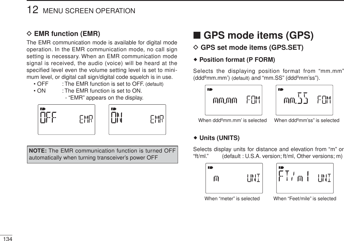
![16216 OPTIONSThe optional HM-75A allows you to remotely select operat-ing frequencies, memory channels, etc.Remote control functions can be selected from 3 settings. These can be selected with “MIC” in FUNC set mode (SET).MENU ¶ SET ¶ FUNC ¶MIC (p. 126) (Push [MENU ]), (Push [](2)/[](8), then push [ ](5).)ABSpeakerEarphone jackPTT switchOFF ONLOCKTransmit LED MicrophoneThe HM-75A has a lock switch on the backside to prevent accidental frequency changes, etc.Be sure to turn power OFF when plugging/unplugging the HM-75A to/from the [SP/MIC] jack.• NORM-1: (default)[A] Selects band.[B] Toggles VFO mode and memory mode.[Y]Frequency or memory channel “UP.”[Z]Frequency or memory channel “DOWN.”• NORM-2: [A] Toggles the monitor function.[B] Toggles VFO mode and memory mode.[Y]Frequency or memory channel “UP.”[Z]Frequency or memory channel “DOWN.”• SIMPLE:[A] Toggles the monitor function.[B] Selects call channel C0.[Y] Selects memory channel 0 in memory mode.[Z] Selects memory channel 1 in memory mode.SIMPLE mode can select only 3 channels and is useful for group operations during touring, etc.VFO mode cannot be selected via the microphone when SIMPLE mode is selected.N Optional HM-75A R O CO ROL P R CROP O](https://usermanual.wiki/ICOM-orporated/315500.User-Manual-3/User-Guide-1070571-Page-50.png)
![16316OPTIONS12345678910111213141516171819• COMMON (NORM-1/NORM-2/SIMPLE): [A] Transmits T-CALL (1750 Hz tone) while pushing [PTT].[Y]Volume “UP” while operating the monitor function.[Z]Volume “DOWN” while operating the monitor function.- When transceiver is selected DR mode:[A] Selects access repeater selection.[B] Selects your call sign and link repeater selection.[Y] Repeater selection or station call sign selection “UP.”[Z] Repeater selection or station call sign selection “DOWN.”D DR mode operation using HM-75Aq Push [A] to enter the access repeater selection on DR mode.AppearRepeater selectionindicatorw Push [Y] or [Z]to select the access repeater.e Push [B] to enter the your call sign selection.UR selectionindicatorr Push [Y] or [Z]to select the your call sign.t Push [B] to enter the link repeater (RPT2) selection.y Push [Y] or [Z]to select the link repeater.u Push [PTT] to transmit; release to receive.](https://usermanual.wiki/ICOM-orporated/315500.User-Manual-3/User-Guide-1070571-Page-51.png)
![16416 OPTIONSq Turn the transceiver power OFF.w Remove the rubber cap. from the [SP/MIC] jack.e Connect the HM-189GPS to the [SP/MIC] jack.r Turn the transceiver power ON, then push the top key of the HM-189GPS to turn the GPS receiver power ON.• Key illumination lights when GPS receiver is turned ON. “G” indicator blinks on the transceiver’s display.• Key illumination blinks when GPS receiver receives GPS signals. Then “G” indicator stays ON on the transceiver’s display.t Position, elevation, time, direction, etc. can be displayed. See Section 8 “GPS/GPS-A OPERATION” for details.GPS indicatorThe optional HM-189GPS has a GPS receiver and allows you to operate the IC-80AD’s GPS functions.q PTT SWITCHPush and hold to transmit; release to receive.w TOP KEYPush to turn the GPS receiver’s power ON and OFF.• Key illumination lights when GPS receiver is turned ON. Key illumination lights OFF when it’s OFF. • Key illumination blinks when GPS receiver receives GPS signals.SpeakerPTT switchTOP keyMicrophoneGPS antennaqwN Optional HM-189GPS PP RCROPOCAUTION!: Turn power OFF the transceiver before connecting/disconnecting HM-189GPS to/from the [SP/MIC] jack.D GPS receiver power ON](https://usermanual.wiki/ICOM-orporated/315500.User-Manual-3/User-Guide-1070571-Page-52.png)