ICOM orporated 315500 VHF/UHF Amateur Transceiver User Manual 3
ICOM Incorporated VHF/UHF Amateur Transceiver 3
Contents
- 1. User Manual 1
- 2. User Manual 2
- 3. User Manual 3
User Manual 3
113
12
MENU SCREEN OPERATION
1
2
3
4
5
6
7
8
9
10
11
12
13
14
15
16
17
18
19
N General
MENU screen is used for programming infrequently changed
values or conditions of functions.
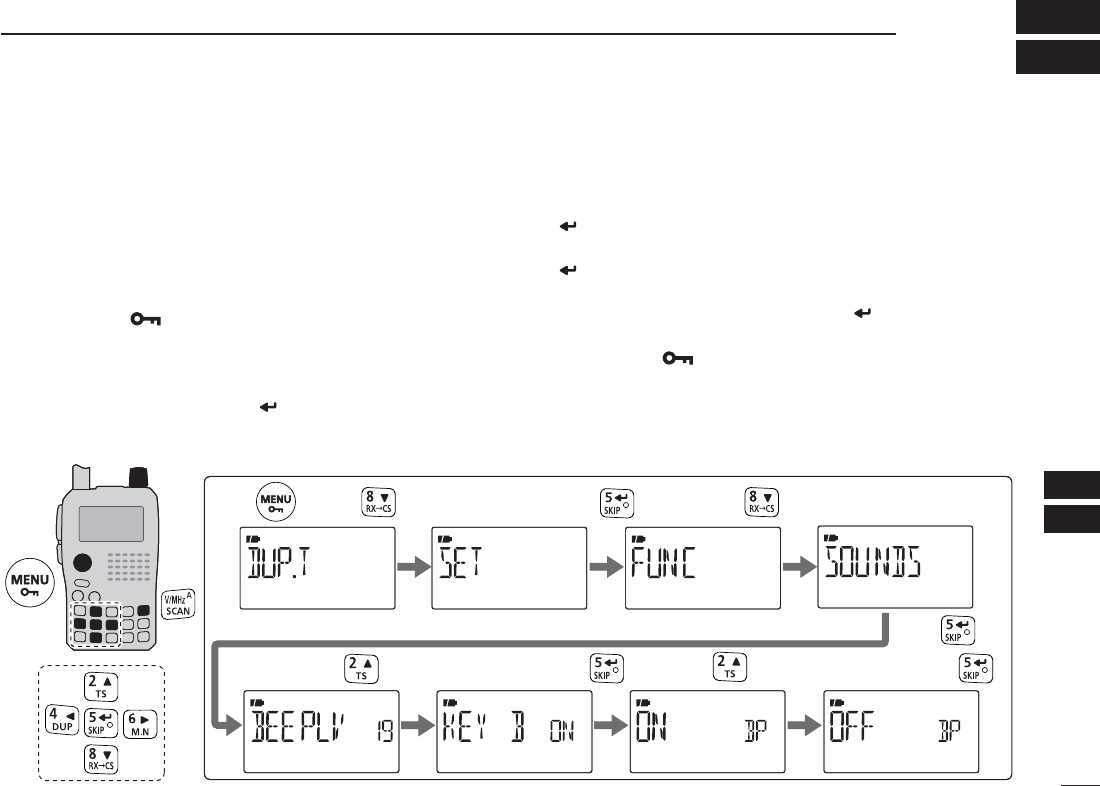
D Entering MENU screen and operation
e.g.) Set “KEY B (Key-touch beep)” to OFF.
qPush [MENU ] to enter MENU screen.
•“DUP.T,” “SCAN,” “SET,” “DV SET,” “CALL-S,” “RX-CS,” “MES-
SAG,” “RPT-L” or “GPS” appears.
w Push [](2) or [](8) (or rotate [DIAL]) to select the de-
sired menu group, then push [](5) (or [](6)).
e When “SET” is selected, push [](2) or [](8) (or rotate
[DIAL]) to select the desired function group, then push
[](5) (or [](6)).
r Push [](2) or [](8) to select the desired item, then push
[](5) (or [](6)).
t Push [](2) or [](8) (or rotate [DIAL]) to select the de-
sired value or condition, then push [](5) (or [](4)) to
return to the setting item selection mode.
y Push [MENU ] (or [V/MHz]) to return to frequency indi-
cation, repeat steps w to r to set another items.
[DIAL]
Enter menu screen
Push to select “SET.”
Push . Push .
PL Set “KEY B (Key-touch beep)” to OFF.
Push .
Push .Push to select “KEY B.” Push to select “OFF,” then push .
Push to select “SOUNDS.”
114
12 MENU SCREEN OPERATION
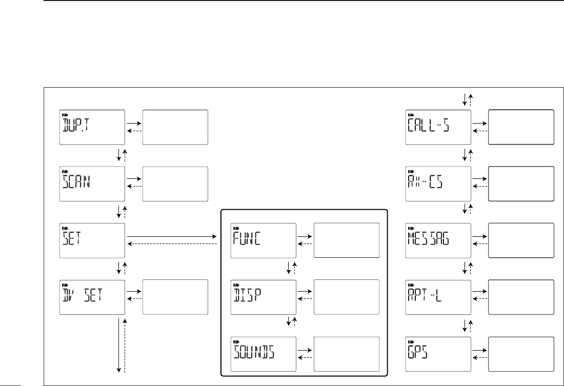
NMENU screen indication and arrangement
MENU screen shows one of the following indication.
• P Independent
items
(see p. 117)
• SCAN mode
• SET mode
• DV SET mode
• CALL-S mode
• RX-CS mode
• MESSAG mode
• RPT-L mode
• GPS mode
• FUNC mode
• DISP mode
• SOUNDS mode
Independent
items
(see p. 119)
Independent
items
(see p. 130)
Independent
items
(see p. 127)
Independent
items
(see p. 122)
Independent
items
(see p. 128)
Independent
items
(see p. 39)
Independent
items
(see p. 66)
Independent
items
(see p. 134)
Independent
items
(see p. 49)
Independent
items
(see p. 36)
115
12
MENU SCREEN OPERATION
1
2
3
4
5
6
7
8
9
10
11
12
13
14
15
16
17
18
19
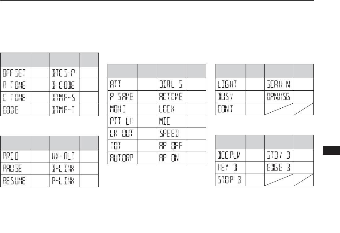
NItems listItems list
D DUP.T mode
Item
indication Ref. Item
indication Ref.
p. 117 p. 118
p. 117 p. 118
p. 117 p. 119
p. 118 p. 119
D SCAN mode
Item
indication Ref. Item
indication Ref.
p. 119 p. 120
p. 119 p. 120
p. 120 p. 121
SET mode
D FUNC mode
Item
indication Ref. Item
indication Ref.
p. 122 p. 125
p. 123 p. 125
p. 123 p. 125
p. 123 p. 126
p. 124 p. 126
p. 124 p. 126
p. 124 p. 126
D DISP mode
Item
indication Ref. Item
indication Ref.
p. 127 p. 128
p. 127 p. 128
p. 127
D SOUNDS mode
Item
indication Ref. Item
indication Ref.
p. 128 p. 129
p. 128 p. 129
p. 129
116
12 MENU SCREEN OPERATION
D DV SET mode
Item
indication Ref. Item
indication Ref.
p. 130 p. 132
p. 130 p. 132
p. 130 p. 132
p. 131 p. 133
p. 131 p. 133
p. 131 p. 133
p. 131 p. 134
p. 132
D CALL-S mode
Item
indication Ref. Item
indication Ref.
p. 37 p. 38
p. 38 p. 36
D RX-CS mode
See p. 49 for details.
D MESSAG mode
Item
indication Ref. Item
indication Ref.
p. 66 p. 77
p. 67 p. 78
D RPT-L mode
Item
indication Ref. Item
indication Ref.
p. 40 p. 45
D GPS mode
Item
indication Ref. Item
indication Ref.
p. 134 p. 86
p. 78 p. 87
p. 80 p. 136
p. 82 p. 140
p. 83
• GPS.SET mode
Item
indication Ref. Item
indication Ref.
p. 134 p. 135
p. 134 p. 135
p. 135
117
12
MENU SCREEN OPERATION
1
2
3
4
5
6
7
8
9
10
11
12
13
14
15
16
17
18
19
N DUP/TONE items (DUP.T)
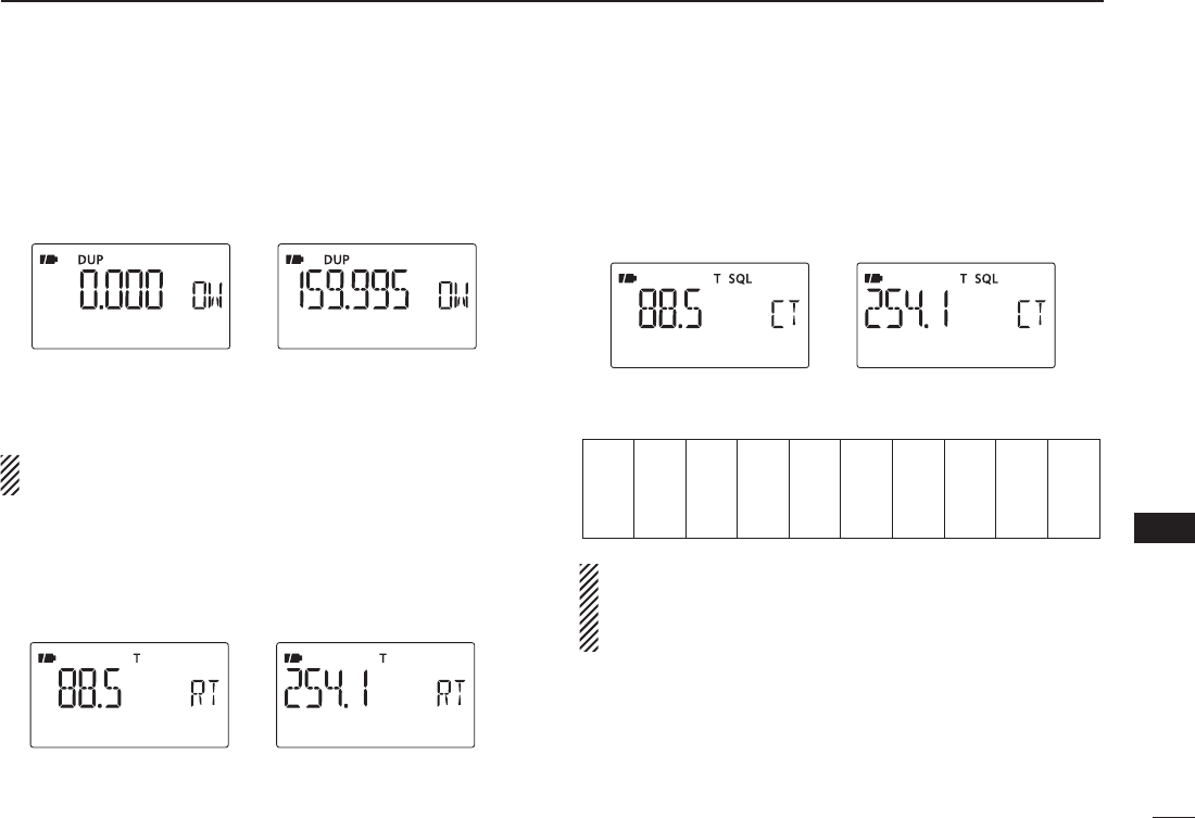
D Offset frequency (OFFSET)
Sets the offset frequency for duplex (repeater) operation within
the range of 0 to 159.995 MHz.
The default value may differ according to the selected fre-
quency band (before accessing DUP.T set mode) and transceiver
version.
The selected tuning step in VFO mode is used when set-
ting the offset frequency.
D Repeater tone frequency (R TONE)
Selects subaudible tone frequency for accessing a repeater,
etc. 50 tone frequencies (67.0–254.1 Hz) are available.
(default: 88.5)
D TSQL frequency (C TONE)
Selects tone frequency for tone squelch or pocket beep op-
eration from of 50 available frequencies (67.0–254.1 Hz).
(default: 88.5)
• Available subaudible tone frequencies
67.0
69.3
71.9
74.4
77.0
79.7
82.5
85.4
88.5
91.5
94.8
97.4
100.0
103.5
107.2
110.9
114.8
118.8
123.0
127.3
131.8
136.5
141.3
146.2
151.4
156.7
159.8
162.2
165.5
167.9
171.3
173.8
177.3
179.9
183.5
186.2
189.9
192.8
196.6
199.5
203.5
206.5
210.7
218.1
225.7
229.1
233.6
241.8
250.3
254.1
The transceiver has 50 tone frequencies and conse-
quently their spacing is narrow compared with units hav-
ing 38 tones. Therefore, some tone frequencies may re-
ceive interference from adjacent tone frequencies.
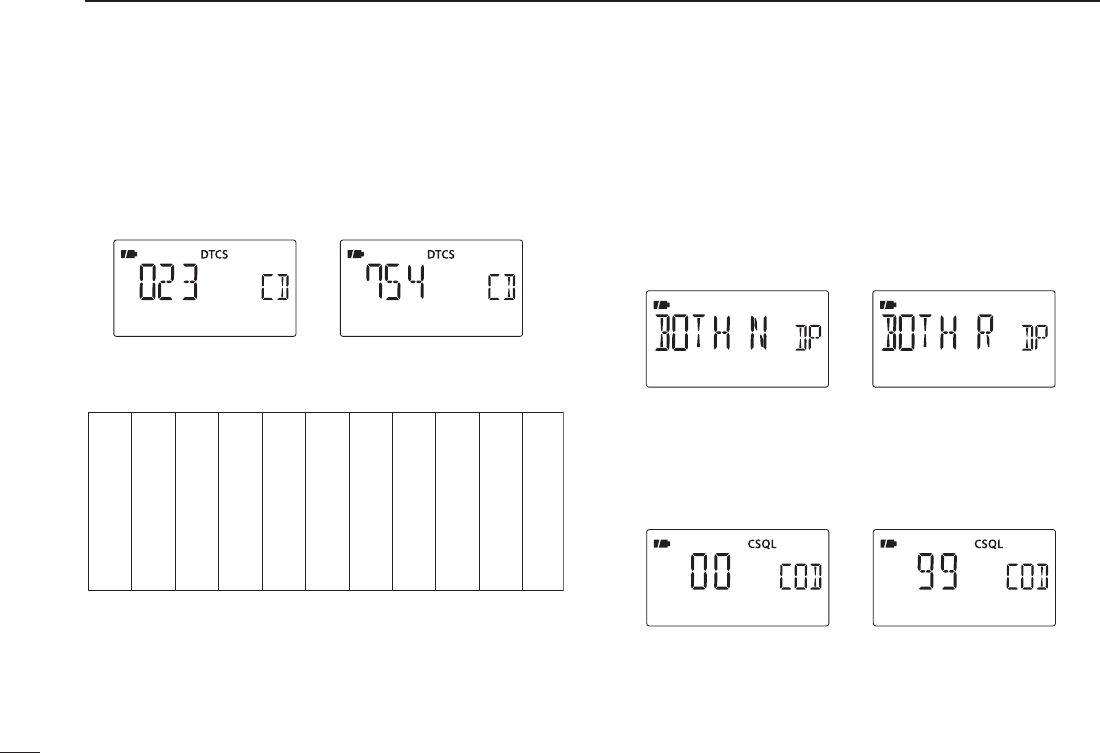
DDTCS code (CODE)
Selects DTCS (both encoder/decoder) code for DTCS squelch
operation. Total of 104 codes (023–754) are available.
(default: 023)
• Available DTCS codes
023
025
026
031
032
036
043
047
051
053
125
131
132
134
143
145
152
155
156
162
245
246
251
252
255
261
263
265
266
271
356
364
365
371
411
412
413
423
431
432
506
516
523
526
532
546
565
606
612
624
054
065
071
072
073
074
114
115
116
122
165
172
174
205
212
223
225
226
243
244
274
306
311
315
325
331
332
343
346
351
445
446
452
454
455
462
464
465
466
503
627
631
632
654
662
664
703
712
723
731
732
734
743
754
DDTCS polarity (DTCS-P)
Sets DTCS polarity from “BOTH N” (TX/RX: normal), “TN-RR”
(TX: normal, RX: reverse), “TR-RN” (TX: reverse, RX: normal) and
“BOTH R” (TX/RX: reverse).(default: BOTH N)
Transmitting or receiving DTCS code’s polarity is sets by this
item at transmitting side and receiving side respectively.
TX/RX: Normal polarity TX/RX: Reverse polarity
D Digital code (D CODE)
Sets the desired digital code for digital code squelch opera-
tion. Total of 100 codes (00–99) are available. (default: 00)
118
12 MENU SCREEN OPERATION
119
12
MENU SCREEN OPERATION
1
2
3
4
5
6
7
8
9
10
11
12
13
14
15
16
17
18
19
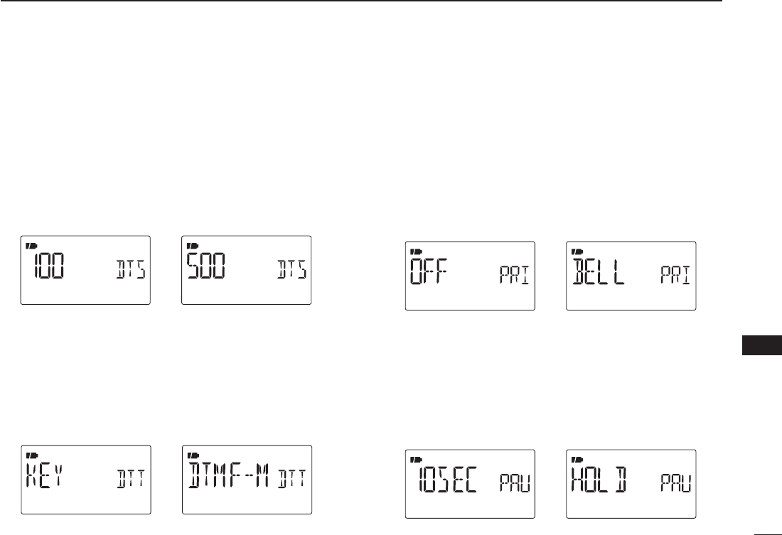
D DTMF speed (DTMF-S)
Select the desired DTMF transmission speed from 100 msec,
200 msec, 300 msec, 500 msec.
• 100 : 100-msec. interval; 5.0 characters per second
(default)
• 200 : 200-msec. interval; 2.5 characters per second
• 300 : 300-msec. interval; 1.6 characters per second
• 500 : 500-msec. interval; 1.0 character per second
D DTMF TX key (DTMF-T)
Selects DTMF transmitting code when pushing and holding
[PTT], then pushing one of the keypad buttons.
• KEY : [1]–[9], [0], [A], [B], [C], [D], [E](1) or [F](#)
DTMF tones are transmitted when the key
is pressed. (default)
• DTMF-M : The DTMF memory contents Ch01–Ch10
and transmitted.
N Scan items (SCAN)
D Priority watch (PRIO)
Activates priority watch or priority watch with alert (Bell).
• OFF : The priority watch is turned OFF. (default)
• ON : The transceiver checks the memory channel fre-
quency every 5 sec.
• BELL : The transceiver checks the memory channel
frequency every 5 sec. You can be alerted with
beeps and blinking “S.”
D Scan pause timer (PAUSE)
Selects the scan pause time. When receiving signals, the
scan pauses according to the scan pause timer.
• 2–20 SEC : Scan pauses for 2–20 sec. while receiving a
signal in 2 sec. steps. (default: 10 sec.)
• HOLD : Scan pauses on a received signal until it dis-
appears.
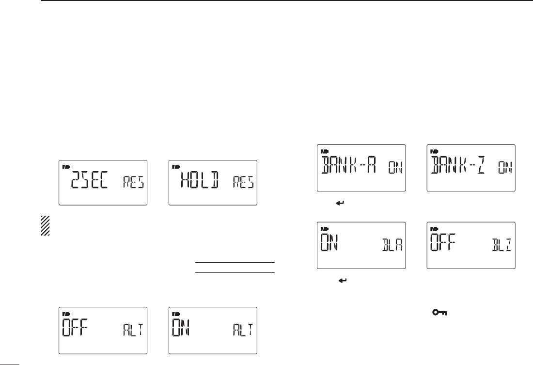
D Scan resume timer (RESUME)
Selects the scan resume time from a pause after the received
signal disappears.
• 0 SEC : Scan resumes immediately after the received
signal disappears.
• 1–5 SEC: Scan pauses 1–5 sec. after the received signal
disappears. (default: 2 sec.)
• HOLD : Scan remains paused on the received signal
according to the scan pause timer even if it dis-
appears. Rotate [DIAL] to resume manually.
Scan resume timer must be set shorter than scan pause
timer (previous item), otherwise this timer cannot be acti-
vated.
U.S.A. version only
D Weather alert (WX-ALT)
Turns weather alert function ON and OFF. (p. 153)
(default: OFF)
D Memory bank link function (B-LINK)
Sets the memory bank link function ON (default) and OFF.
The link function provides continuous bank scan, scanning all
channels in the selected banks during bank scan.
• Bank link setting
qPush [](2) or [](8) to select the bank that you want to
change the link setting.
wPush [ ](5) to enter bank setting.
ePush [](2) or [](8) to select the setting.
rPush [](5) to set and return to the BANK selection
screen.
tPush [](2) or [](8) to select next bank and repeat
steps w to r, or push [MENU ]to exit MENU screen
operation.
120
12 MENU SCREEN OPERATION
121
12
MENU SCREEN OPERATION
1
2
3
4
5
6
7
8
9
10
11
12
13
14
15
16
17
18
19
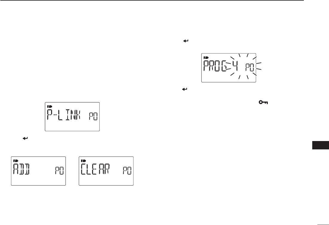
D Program scan link function (P-LINK)
Sets the program scan link function. The link function pro-
vides continuous program scan in the selected program scan
number during program scan.
Default settings for P-LINK P0 to P-LINK P9 are PROG 1 to
PROG 24 are linked and PROG 0 is no-linked.
• Program scan link setting
qPush [](2) or [](8) to select the program scan link
number that you want to change.
wPush [ ](5) to enter the program scan link setting.
ePush [](2) or [](8) several times to select the setting
“ADD” or “CLEAR.”
• When “ADD” is selected, only no-linked program scans are dis-
played. When “CLEAR” is selected, only linked program scans
are displayed.
rPush [ ](5), then push [](2) or [](8) to select the
desired program scan
.
tPush [ ](5)
to set the program scan link setting.
yRepeat steps r and t to add or clear the program
scan to/from the link, or push [MENU ]to exit MENU
screen operation.
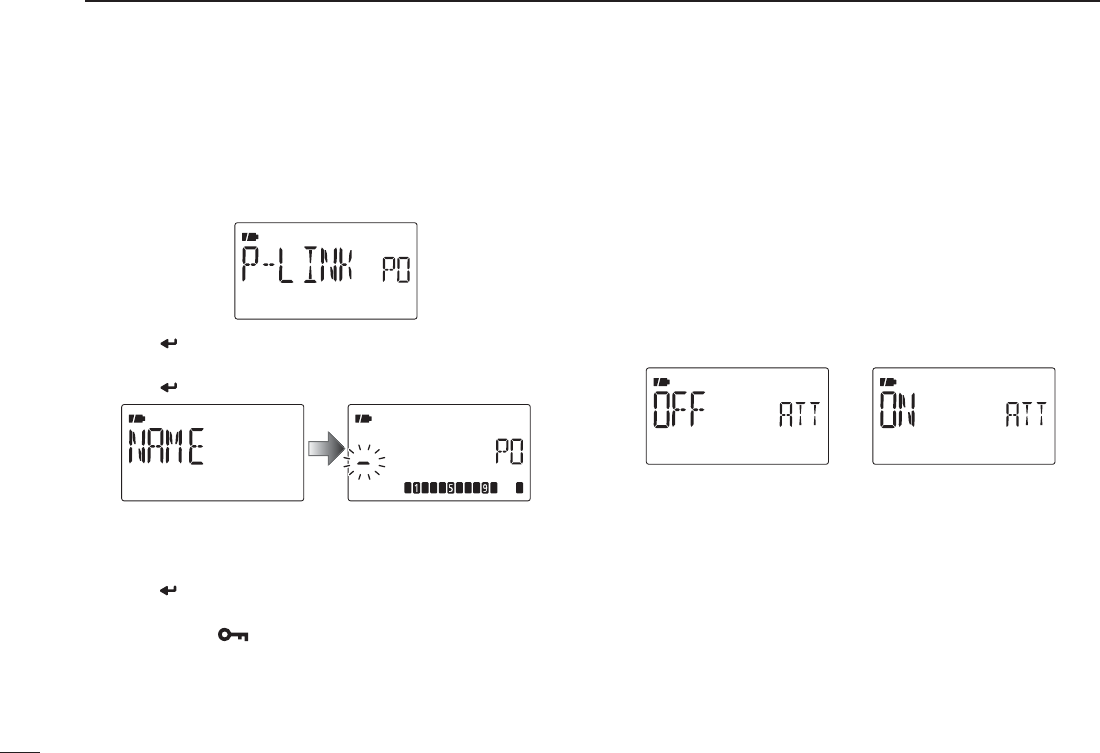
• Program scan link setting
qPush [](2) or [](8) to select the program scan link
number that you want to program the name.
wPush [ ](5) to enter the program scan link setting.
ePush [](2) or [](8) several times to select “NAME.”
ePush [](5) to enter the program scan link setting.
r Push [](2) or [](8) to select the desired character,
number, symbol or space; push [](6) or [](4) to move
the cursor right or left, respectively.
t Push [](5) to program the repeater name and exit the
state.
y Push [MENU ]to exit MENU screen operation.
N Set mode items (SET)
Function set mode items (FUNC)
D Attenuator (ATT)
The attenuator prevents distortion of a desired signal by very
strong RF signals near the desired frequency or when very
strong electric fields, such as from a broadcasting station, are
present at your location.
Select the attenuator function ON and OFF (default).
122
12 MENU SCREEN OPERATION
123
12
MENU SCREEN OPERATION
1
2
3
4
5
6
7
8
9
10
11
12
13
14
15
16
17
18
19
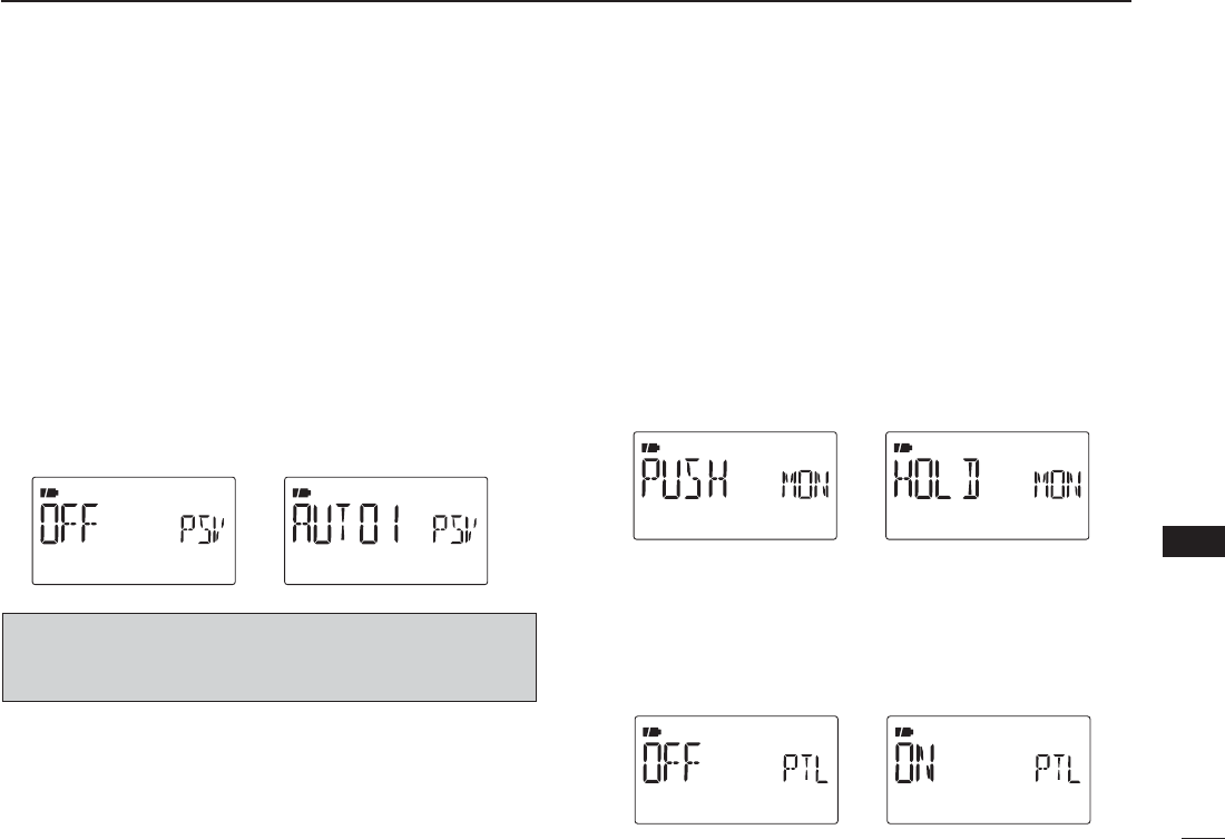
D Power save (P SAVE)
The power save function reduces the current drain to con-
serve battery power. This power save function can be turned
OFF, if desired, by turning power ON and OFF.
• “AUTO1” selects “1:4” duty ratio when receiving no signal for 5
sec., then “1:8” 60 sec. after that.
• “AUTO2”
suppresses the consumption of the battery by stopping
the operation of a digital block of the DV mode in addition to the op-
eration of Auto1.
NOTE: Power save function is disable when using the ex-
ternal power supply (More than 10 V DC) or if the Auto re-
play function is set to ON (p. 130).
D Monitor key action (MONI)
The monitor key, [SQL], can be set as a ‘sticky’ key. When set
to the sticky condition, each push of [SQL] toggles the moni-
tor function ON and OFF.
• PUSH: Pushing and holding [SQL] to monitor the fre-
quency. (default)
• HOLD : Push [SQL] momentarily to monitor the frequency
and push momentarily again to cancel it.
DPTT lock (PTT LK)PTT lock (PTT LK)
Turns the PTT lock function ON and OFF.
This function inhibits transmission with [PTT] is inhib-
ited when ON is selected to prevent accidental trans-
mission, etc. (default: OFF)
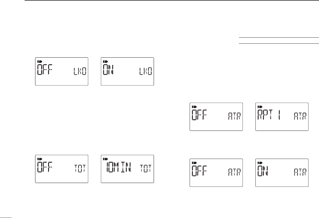
D Busy lockout (LK OUT)
Turns the busy lockout function ON and OFF.
This function inhibits transmission while receiving a
signal or when the squelch is open. (default: OFF)
D Time-out timer (TOT)
To prevent accidental prolonged transmission, etc., the trans-
ceiver has a time-out timer. This function cuts transmission
OFF after 1, 3, 5 10, 15 or 30 min. of continuous transmis-
sion. This timer can be cancelled.
• OFF : The time-out timer is turned OFF. (default)
• 1 to 30 MIN : The transmission is cut OFF after the set
period elapses.
DAuto repeater (AUTORP)
U.S.A. and Korean versions only
The auto repeater function automatically turns ON or OFF
the duplex operation and tone encoder. The offset and re-
peater tone is not changed by the auto repeater function.
Reset these frequencies, if necessary.
U.S.A. version:
• OFF : The auto repeater function is turned OFF.
• RPT1 : Activates for duplex only. (default)
• RPT2 : Activates for duplex and tone.
Korean version:
• OFF : The auto repeater function is turned OFF.
• ON : Activates duplex and tone. (default)
124
12 MENU SCREEN OPERATION
125
12
MENU SCREEN OPERATION
1
2
3
4
5
6
7
8
9
10
11
12
13
14
15
16
17
18
19
D Dial speed acceleration (DIAL S)
The dial speed acceleration automatically speeds up the tun-
ing dial speed when rotating [DIAL] rapidly.
• OFF : The dial speed acceleration is turned OFF.
• ON : The dial speed acceleration is tuned ON.
(default)
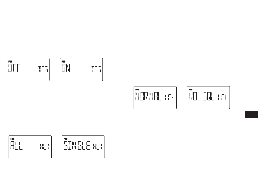
D Active band (ACTIVE)
Allows continuous frequency selection of the operating fre-
quency across all bands.
• SINGLE : A single operating frequency can be se-
lected within the current band. Push
[BAND] for band selection in this case.
• ALL : The operating frequency can be selected
continuously. (default)
D Key lock type (LOCK)
While the key lock function is ON, [PWR], [PTT], [SQL],
[VOL] and [MENU](Lock function only) can still be accessed.
Accessible keys can be set to 1 of 4 groups.
• NORMAL: [PWR], [PTT], [SQL], [VOL] and [MENU]
(Lock function only) accessible. (default)
• NO SQL : [PWR],[PTT],[VOL] and [MENU] (Lock func-
tion only) are accessible.
• NO VOL : [PWR],[PTT],[SQL] and [MENU] (Lock func-
tion only) are accessible.
• ALL : [PWR],[PTT] and [MENU] (Lock function only)
are accessible.
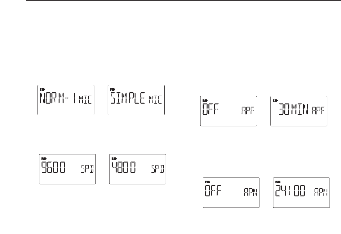
D Microphone simple mode (MIC)
Microphone simple mode is used to change the function as-
signments for keys on the optional HM-75A REMOTE CONTROL
SPEAKER-MICROPHONE. (p. 162)
• SIMPLE
• NORM-1 (default)
• NORM-2
D DATA speed (SPEED)
Selects the data speed of [DATA] jack from 4800 bps and
9600 bps (default) for GPS receiving, etc.
When 4800 bps is selectedWhen 9600 bps is selected
D Auto power OFF (AP OFF)
The transceiver can be set to automatically turn OFF after a
specified time period with a beep when no key operations are
performed.
30 min., 60 min, 90 min, 120 min and OFF (default) can be
specified. The specified time period is retained even when the
transceiver is turned OFF by the auto power OFF function. To
cancel the function, select “OFF” in this item.
D Auto power ON (AP ON)
Auto power ON function turns the transceiver power ON auto-
matically after passing the set time period from power OFF.
Select the desired time period within 30 minutes to 24 hours
in 30 minutes steps and OFF. (default: OFF)
126
12 MENU SCREEN OPERATION
127
12
MENU SCREEN OPERATION
1
2
3
4
5
6
7
8
9
10
11
12
13
14
15
16
17
18
19
Display set mode items (DISP)
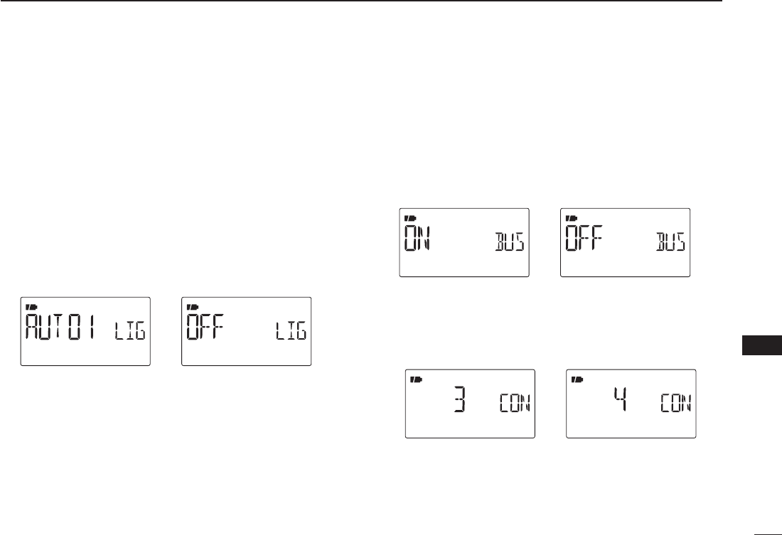
D Display backlighting (LIGHT)
The transceiver has display backlighting with a 5 sec. timer
for night time operation. The display backlighting can be
turned ON continuously or turned OFF, if desired.
• OFF : The backlight is turned OFF.
• ON : The backlight continuously lights ON.
• AUTO1 : Lights when an operation is performed, goes
out after 5 sec. (default)
• AUTO2 : Lights when an operation is performed, goes
out after 5 sec with a battery pack or battery
case operation, or stays ON when using the ex-
ternal power supply (More than 10 V DC).
D Busy LED (BUSY)
The TX/RX indicator lights green while receiving a signal or
when the squelch is open. This indication can be turned OFF
to conserve the battery power, if desired.
• OFF : The indicator does not function even if a signal is
received.
• ON : The indicator lights green while receiving a signal
or when the squelch is open. (default)
D LCD contrast (CONT)
The contrast of the LCD can be selected from 4 levels.
• 1 (Low contrast) to 4 (High contrast) (default: 3)
High contrast (4)Default (3)
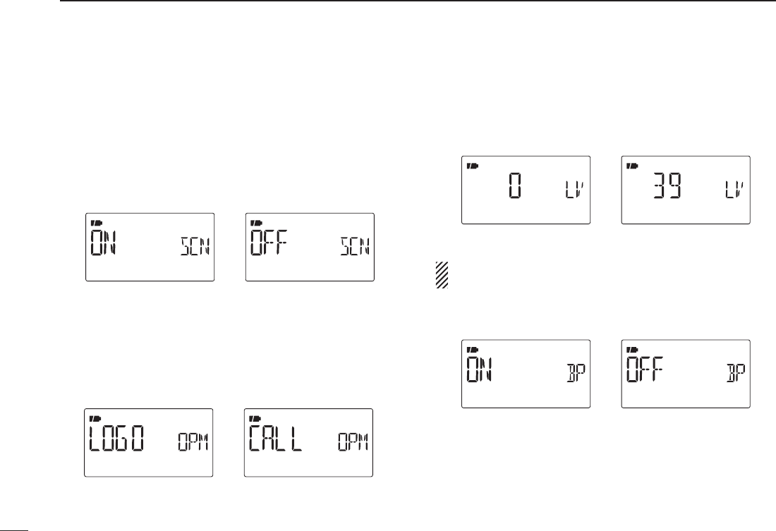
D Scan name (SCAN N)
The programmed scan, programmed link scan or bank name
is displayed during the scan type selection.
• OFF : The programmed scan, programmed link scan or
bank name is not displayed.
• ON : The programmed scan, programmed link scan or
bank name is displayed. (default)
D Opening message (OPN.MSG)
The opening message indication that is displayed at power
ON is selectable from Icom logo, my call sign or skipped.
• OFF : Opening message indication is skipped.
• LOGO : Icom logo is displayed at power ON. (default)
• CALL : The set my call sign is displayed at power ON.
When LOGO is selected When Call sign is selected
Sounds set mode items (SOUNDS)
D Beep output level (BEEPLV)
Adjusts the key-touch beep tone level to the desired level
within 39 levels. (default: 19)
Minimum level Maximum level
The key-touch beep (following item) must be set to ON to
have a beep tone.
D Key-touch beep (KEY B)
Turns the key-touch beep ON or OFF. (default: ON)
Key-touch beep ON Key-touch beep OFF
128
12 MENU SCREEN OPERATION
129
12
MENU SCREEN OPERATION
1
2
3
4
5
6
7
8
9
10
11
12
13
14
15
16
17
18
19
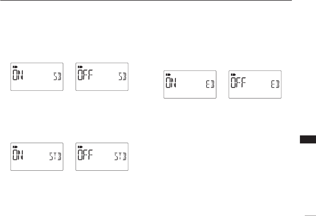
D Scan stop beep (STOP B)
Turns the scan stop beep function ON or OFF. (default: OFF)
Scan stop beep ON Scan stop beep OFF
D Standby beep (STBY B)
Turns the beep emission capability ON and OFF when the
communicating station finishes transmitting or the receive
signal disappears while in the digital mode operation.
(default: ON)
Stand by beep ON Stand by beep OFF
DBand edge beep (EDGE B)
Turns the beep emission capability ON and OFF when the
frequency is changed over the band edge by rotating [DIAL].
(default: ON)
Band edge beep ON Band edge beep OFF
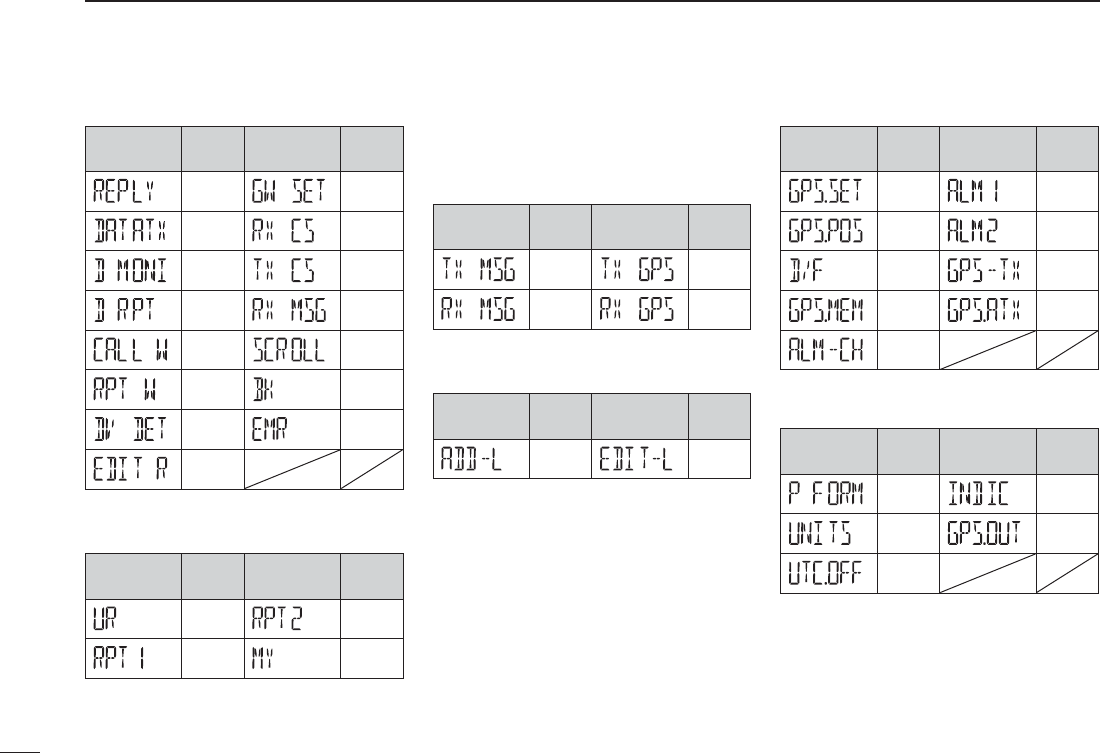
NDV set mode items (DV SET)
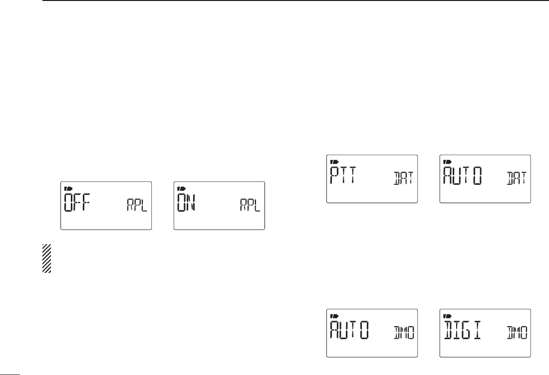
D Auto reply (REPLY)
This function replies to an individual station call even you are
away from the transceiver.
After a manual transmission (pushing [PTT]), the Auto Reply
setting returns to OFF automatically.
• OFF : No reply is performed even if a call is received.
(default)
• ON : Sets the caller's call sign and replies to the call
with the programmed own call sign.
NOTE: When “ON” is set in the auto reply function, the
power save function (p. 123) stop functioning automatically
to receive call sign signal properly.
D DV data TX (DATATX)
During low-speed data operation, auto data transmission
function is available. This function transmits when data has
been input from PC via the [DATA] jack. (default: PTT)
• PTT : Data from [DATA] transmits when [PTT] is
pushed. (default)
• AUTO : Data from [DATA] transmits automatically.
D Digital monitor (D MONI)
Sets the desired monitoring mode during digital mode opera-
tion from “Auto,” “Digital” and “Analog.”
• AUTO :
The transceiver sets monitoring mode to FM and
DV according to the received signal. (default)
• DIGI : Monitors in DV mode.
• ANALOG : Monitors in FM mode.
130
12 MENU SCREEN OPERATION
131
12
MENU SCREEN OPERATION
1
2
3
4
5
6
7
8
9
10
11
12
13
14
15
16
17
18
19
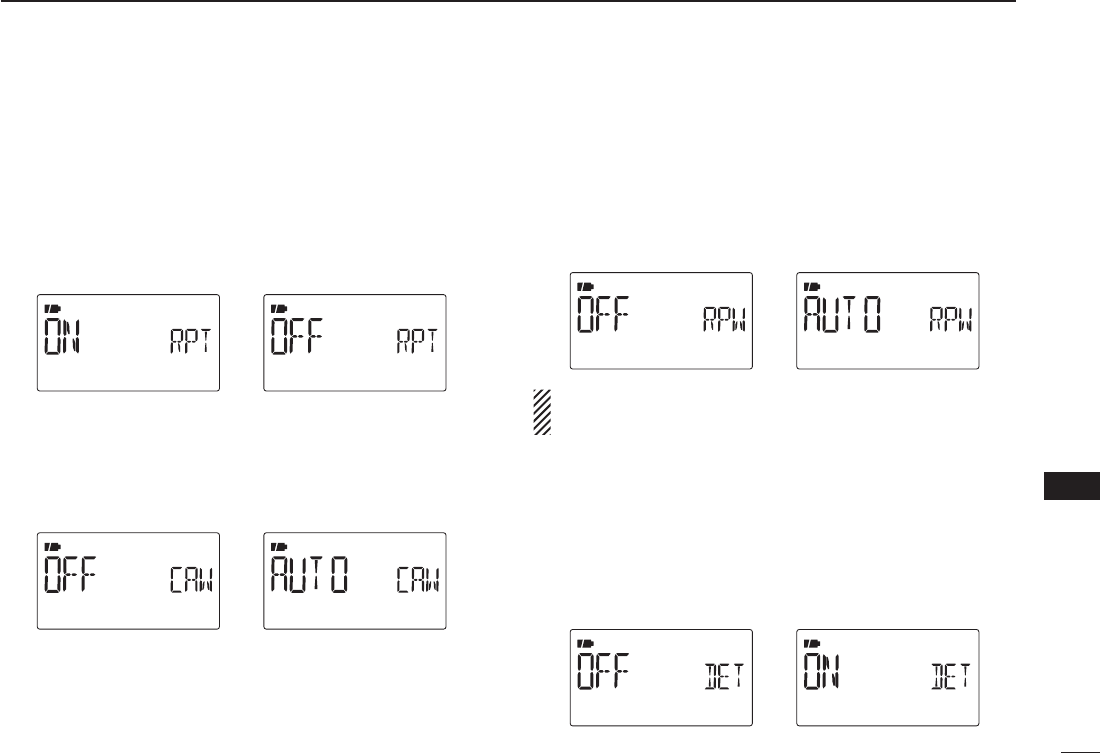
D Digital repeater setting (D RPT)
When accessing a digital repeater that the repeater call sign
is different than the transceiver’s current call sign, the re-
peater call sign can be stored into “RPT1” of the current call
sign automatically by reading the repeater’s down link signal.
(default: ON)
DRX call sign auto write (CALL W)
When your own individual station call is received, the calling
station call sign can be automatically set in “UR” of the cur-
rent call sign. (default: OFF)
D Repeater call sign auto write (RPT W)
When your own individual station call is received via the dig-
ital repeater, the repeater call sign can be set into “RPT1”
and/or “RPT2” automatically by reading the repeater’s down
link signal. (default: OFF)
The transceiver sets the received repeater call sign for op-
eration, over-writing the current repeater call sign.
DDV auto detect (DV DET)
When a signal other than DV mode is received during DV
mode operation, the transceiver has capability of automatic
FM mode selection.
• OFF : Operating mode is fixed in DV. (default)
• ON : The transceiver automatically selects FM
mode for temporary operation.
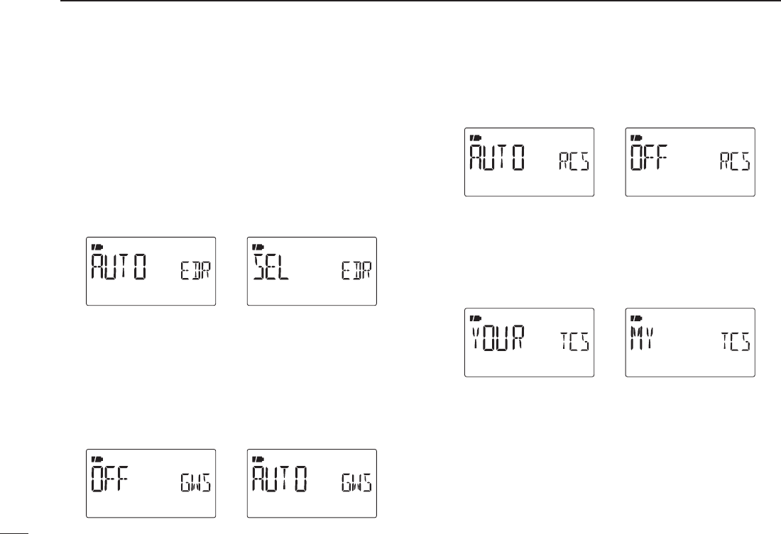
DCall sign edit record (EDIT R)
Selects call sign programming when the call sign is edited or
corrected with the pre-programmed call sign.
• OFF : The edited or corrected call sign is overwrit-
ten.
• SEL : The edited or corrected call sign is pro-
grammed into the selected call sign memory.
• AUTO : The edited or corrected call sign is pro-
grammed into a blank channel automatically.
(default)
DAuto gateway setting (GW SET)
When the repeater has gateway capability and the repeater is
set to the access repeater “RPT1,” the link repeater “RPT2” is
set the same repeater’s call sign with G automatically.
• OFF : Auto gateway setting is disabled. (default)
• AUTO : RPT2 is automatically set as the gateway re-
peater by the RPT1’s call sign.
D RX call sign display (RX CS)
When a call is received, the calling station call sign can be
displayed automatically. (default: AUTO)
D TX call sign display (TX CS)
Selects call sign display function from YOUR, MY and OFF.
When this setting is set to YOUR or MY, the transceiver auto-
matically displays the set station or your own call sign during
DV mode transmission. (default: YOUR)
132
12 MENU SCREEN OPERATION
133
12
MENU SCREEN OPERATION
1
2
3
4
5
6
7
8
9
10
11
12
13
14
15
16
17
18
19
D RX message display (RX MSG)
Sets auto received message display function AUTO and OFF.
When this setting is set to AUTO, the transceiver automati-
cally displays and scrolls the received message.
(default: AUTO)
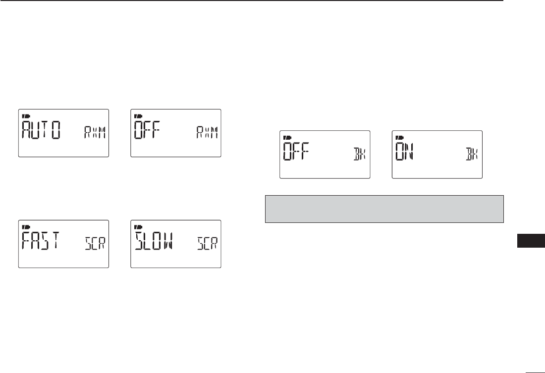
D Scroll speed (SCROLL)
Set the displayed message, call sign, etc. scrolling speed.
• FAST : Scroll speed is set to fast. (default)
• SLOW : Scroll speed is set to slow.
D Break-in function (BK)
The break-in function allows you to break into a conversation
where the two original stations are communicating with call
sign squelch enabled.
• OFF : The break-in function is set to OFF. (default)
• ON : The break-in function is set to ON.
- “BK” appears on the display.
NOTE: The break-in function is turned OFF automatically
when turning transceiver’s power OFF.
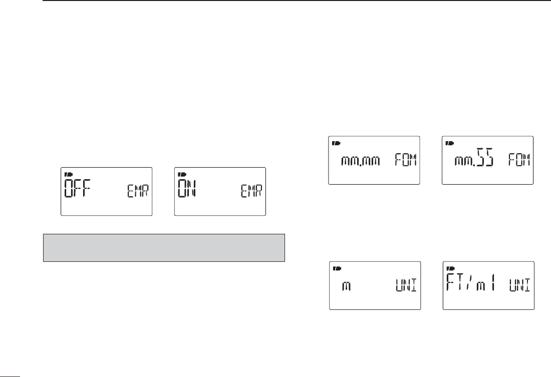
D EMR function (EMR)
The EMR communication mode is available for digital mode
operation. In the EMR communication mode, no call sign
setting is necessary. When an EMR communication mode
signal is received, the audio (voice) will be heard at the
specified level even the volume setting level is set to mini-
mum level, or digital call sign/digital code squelch is in use.
• OFF : The EMR function is set to OFF. (default)
• ON : The EMR function is set to ON.
- “EMR” appears on the display.
NOTE: The EMR communication function is turned OFF
automatically when turning transceiver’s power OFF
NGPS mode items (GPS)
D GPS set mode items (GPS.SET)
Position format (P FORM)
Selects the displaying position format from “mm.mm”
(dddºmm.mm’) (default) and “mm.SS” (dddºmm’ss”).
When dddºmm.mm’ is selected When dddºmm’ss” is selected
Units (UNITS)
Selects display units for distance and elevation from “m” or
“ft/ml.” (default : U.S.A. version; ft/ml, Other versions; m)
When “Feet/mile” is selectedWhen “meter” is selected
134
12 MENU SCREEN OPERATION
135
12
MENU SCREEN OPERATION
1
2
3
4
5
6
7
8
9
10
11
12
13
14
15
16
17
18
19
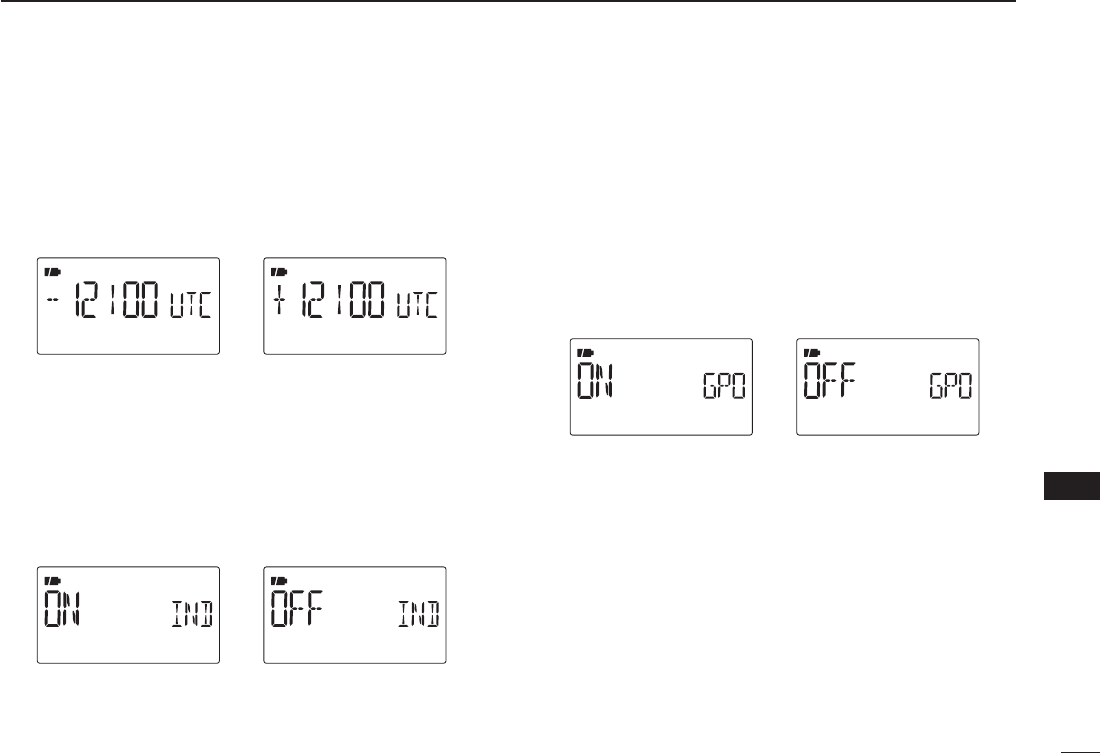
UTC offset (UTC.OFF)
Sets time difference from UTC (Universal Time Coordinated)
within –12:00 to +12:00 range in 5 min. steps. (default: 0:00)
Set to +12:00 hourSet to –12:00 hour
GPS indication (INDIC)
Sets the GPS indicator ON and OFF. (default : ON)
• OFF : “G” indicator does not appear.
• ON : “G” indicator appears on the display when a GPS
receiver is connected and a valid position data is
received; blinks when an invalid data is received.
GPS indication OFFGPS indication ON
GPS data out (GPS.OUT)
Sets the GPS data received from a connected optional GPS
microphone, HM-189GPS to output from [DATA] jack.
• OFF : Transceiver does not output the GPS data.
(default)
• ON : Transceiver outputs the GPS data from [DATA]
jack.
Data output is OFFData output is ON
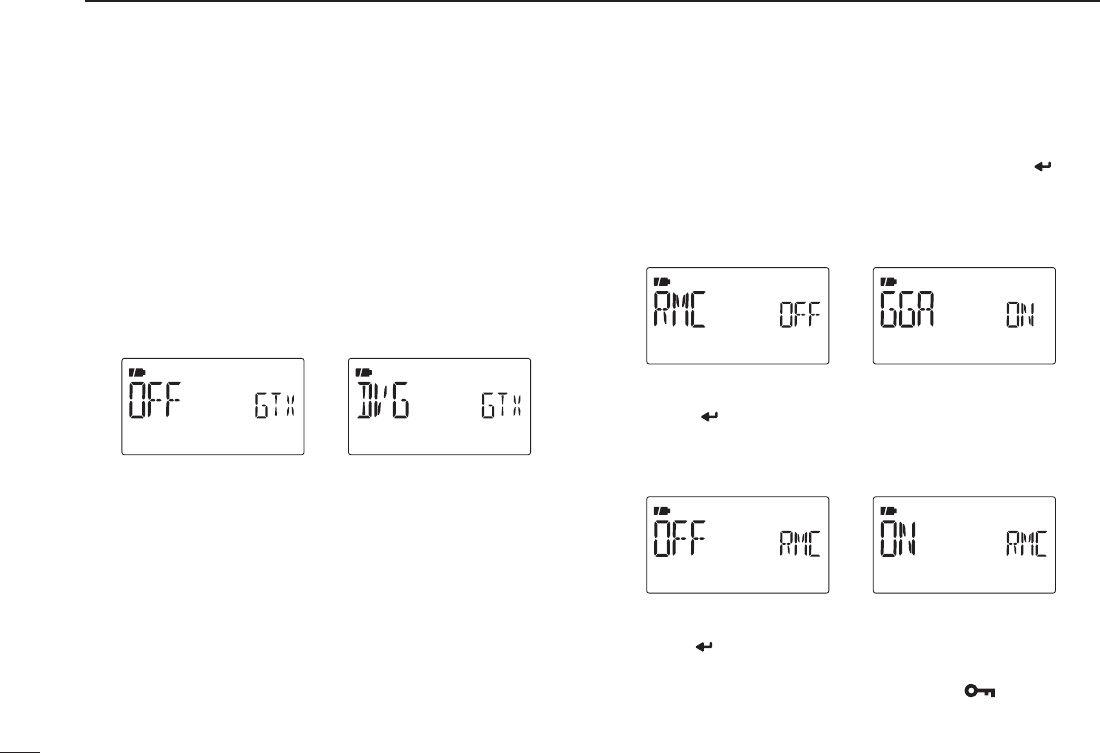
D GPS TX mode items (GPS-TX)
Sets the transmission of data from a connected GPS receiver
ON and OFF.
When the position information is received from a connected
GPS receiver and GPS.ATX (GPS Auto TX Timer ) setting
(p. 140) is set to a specific time, the transceiver automatically
transmits the current position and message at the set inter-
val.
• OFF : Transmitting position data is disabled. (default)
• DVG : Transmitting position data in GPS mode.
• DVA : Transmitting position data in GPS-A mode.
Sentence formatter setting
q Select “DVG” in GPS TX mode item, then push [ ](5) to
enter the sentence formatter selection.
w Push [](2) or [](8) to select the desired sentence
formatter.
• RMC, GGA, GLL, GSA, VTG and GSV are selectable.
GGA sentenceRMC sentence
e Push [ ](5) to enter the desired sentence formatter
selection.
r Push [](2) or [](8) to select the setting.
• See right above for setting details.
RMC sentence: ONRMC sentence: OFF
t Push [ ](5) to set ON/OFF.
y Push [](2) or [](8) to select next sentence and
repeat steps w to t, or push [MENU ] to return to
frequency indication.
• Only four sentence formatters can be activated at same time.
136
12 MENU SCREEN OPERATION
137
12
MENU SCREEN OPERATION
1
2
3
4
5
6
7
8
9
10
11
12
13
14
15
16
17
18
19
• RMC : (Default OFF)
Set RMC sentence ON or OFF.
• GGA : (Default ON)
Set GGS sentence ON or OFF.
• GLL : (Default OFF)
Set GLL sentence ON or OFF.
• GSA : (Default OFF)
Set GSA sentence ON or OFF.
• VTG : (Default OFF)
Set VTG sentence ON or OFF.
• GSV : (Default OFF)
Set GSV sentence ON or OFF.
GPS-A set mode
Enter GPS-A set mode by selecting "DVA" in GPS TX mode,
then push [](5). This set mode is available to set unproto
address, data extension, time stamp, GPS-A symbol and
comment.
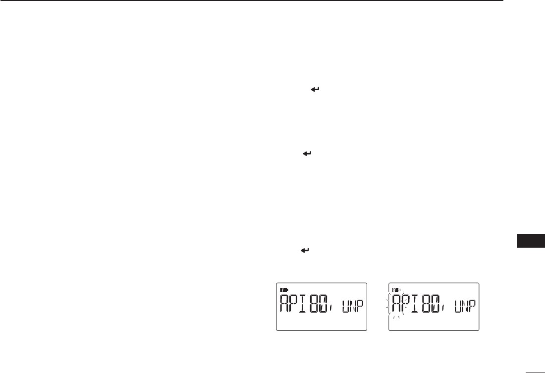
Unproto Address (UNPROT)
56 characters address can be entered for unproto address.
q Push [ ](5) to enter the unproto address edit mode.
w Push [](2) or [](8) to select the desired character.
• The selected character blinks.
• Push [](6) to move the cursor right; push [](4) to move the
cursor left.
• Push [CLR](1) to erase the selected character, or push and hold
[CLR](1) for 1 sec. to erase all characters following the cursor.
e Repeat step w until the desired unproto address is pro-
grammed.
r Push [](5) to program the unproto address and exit the
unproto address edit mode.
t Push [](4) to return to GPS-A set mode screen.
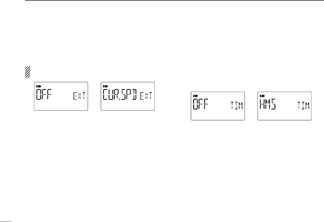
DATA extension (DT EXT)
Sets the data extension capability to “CUR.SPD” (COURSE/
SPEED) or OFF (default).
The transceiver’s course and speed information is additionally
transmitted with position data when “CUR/SPD” is selected.
NOTE: When “CUR/SPD” is selected, number of charac-
ter for “COMMEN” (COMMENT) is limited to 36-character.
Set to course/speedSet data extension to OFF
Time stamp (TIME)
Selects transmitting time stamp type from DHM, HMS and
OFF. This function can be transmitted UTC (Universal Time
Coordinated)time only.
•OFF : No time stamp is transmitted. (default)
•DHM : Time stamp in the format of Day, Hour and
Minute is transmitted.
•HMS : Time stamp in the format of Hour, Minute and
Second is transmitted.
Set to Hour/Minute/SecondSet time stamp to OFF
138
12 MENU SCREEN OPERATION
139
12
MENU SCREEN OPERATION
1
2
3
4
5
6
7
8
9
10
11
12
13
14
15
16
17
18
19
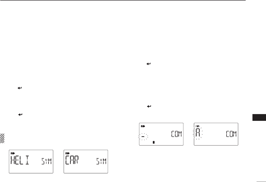
GPS-A symbol (SYMBOL)
Selects the desired GPS-A symbol.
Available symbols: AMBU (Ambulance), BUS (Bus), FIRE
(Fire Truck), BICYCL (Bicycle), YACHT (Yacht), HELI (Heli-
copter), BALLOO (Balloon), AIRCRA (Small Aircraft), SHIP
(Power Boat), CAR (Car): (default), M-CYCLE (Motorcycle),
JEEP (Jeep), RV (Recreational Vehicle), TRUCK (Truck), VAN
(Van) and OTHER (Other).
If “OTHER” is selected, set the desired symbol code as fol-
lows;
q Push [](5) to begin the programming.
w Push [](2) or [](8) to select the 1st character from “\”
and “/.”
e Push [](6) to select the 2nd digit.
r Push [](2) or [](8) to select the 2nd digit character.
t Push [](5) to program the symbol code, then exit pro-
gramming.
y Push [](4) to return to GPS-A set mode screen.
When “OTHER” is selected, check the symbol codes of
APRS®
and set it correctly.
Car is selectedHelicopter is selected
Comment (COMMEN)
Program up to a 43-character* comment. The programmed
comment is transmitted with the GPS position data.
*36-character comment can only be programmed when
“CUR/SPD” (COURSE/SPEED) is selected in DT EXT (Data
extension).
q Push [](5) twice to enter the programming.
w Push [](2) or [](8) to select the desired character.
• The selected character blinks.
• Push [](6) to move the cursor right; push [](4) to move the
cursor left.
• Push [CLR](1) to erase the selected character, or push and hold
[CLR](1) for 1 sec. to erase all characters following the cursor.
e Repeat step w until the desired comment is programmed.
r Push [](5) to program the comment and exit comment
programming.
t Push [](4) to return to GPS-A set mode screen.
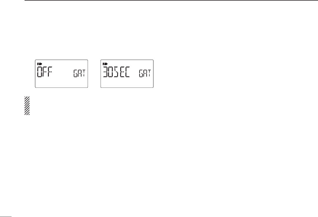
D GPS auto TX timer (GPS.ATX)
Selects the desired interval for automatic position transmis-
sion function from OFF (default), 5, 10, 30 second, 1, 3, 5, 10
and 30 minutes.
NOTE: When four sentence formatter are activated at the
same time (“Sentence formatter setting” on pgs. 136, 137),
“5SEC” can not be selected.
140
12 MENU SCREEN OPERATION
141
13
OTHER FUNCTIONS
1
2
3
4
5
6
7
8
9
10
11
12
13
14
15
16
17
18
19
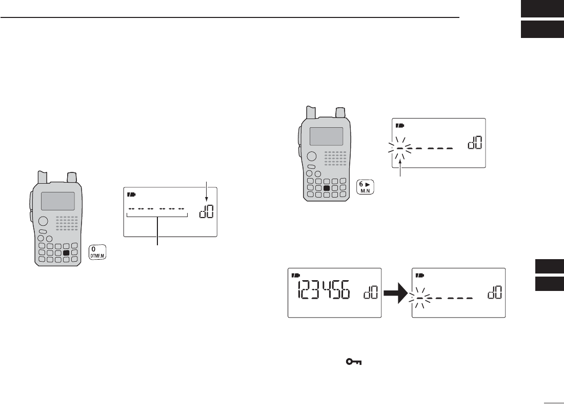
N Programming a DTMF code
DTMF codes are used for autopatching, accessing repeat-
ers, controlling other equipment, etc. The transceiver has 16
DTMF memory channels (D0–D9, DA, DB, DC, DD, DE, DF)
for storage of often-used DTMF codes of up to 24 digits.
q Push and hold [DTMF.M](0) for 1 sec. to enter DTMF
memory.
DTMF memory channel
Blank channel indication
w Push [](2) or [](8) to select the desired DTMF memory
channel.
• “T-CALL” appears when a 1750 Hz tone burst signal is selected.
(p. 33)
• Previously programmed DTMF code is displayed if pro-
grammed.
ePush [](6) to enter programming mode.
The cursor is blinking when
entering programming mode.
rPush the desired keys to input the characters.
•[0]–[9] input “0”–“9,” [A](V/MHz) inputs “A,” [B](M/CALL) inputs
“B,” [C](DR) inputs “C,” [D]() inputs “D,” [#](.) inputs “E (#)” and
[1](BAND) inputs “1(F).”
• Up to 24 digits can be programmed.
Next display appears after
6th digit has been input.
tRepeat step r until the desired code is input.
y Push [MENU ]to program the DTMF code and exit
programming mode.
• Entering 24th digit automatically exits the programming mode.
uPush [V/MHz] to exit DTMF memory.
142
13 OTHER FUNCTIONS
N Transmitting a DTMF code
DTransmitting from DTMF memory
The selected DTMF code is transmitted at each push of the
[SQL] switch while transmitting.
The transmitting speed at which DTMF memories send
individual DTMF characters can be set in “DTMF-S”
(DTMF SPEED) item. (p. 119)
q Set the desired frequency. (p. 23)
wPush and hold [DTMF.M](0) for 1 sec. to enter DTMF
memory.
ePush [](2) or [](8) to select the desired DTMF mem-
ory channel.
r PushPush [ ](5) to set the DTMF
memory.
t PushPush [V/MHz] to exit DTMF
memory.
y While pushingWhile pushing [PTT], push
[SQL] to transmit the se-
lected DTMF code.
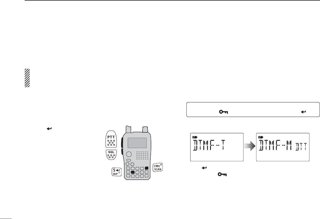
DTransmitting from DTMF memory in VFO
mode
The selected DTMF memory can be transmitted via keypad
directly while transmitting. Pushing [0]–[9], [A], [B], [C], [D],
[#] or [1] to transmit DTMF memory channel (D0–D9, DA,
DB, DC, DD, DE or DF) respectively.
qSet the desired frequency. (p. 23)
w Enter “DTMF-T” in DUP.T set mode.
MENU ¶ DUP.T ¶DTMF-T
(p. 119)
(Push [MENU ]), (Push [](2)/[](8), then push [ ](5).)
e Push [](2) or [](8) to select DTMF transmitting key
(DTMF–M) as below.
r Push [ ](5) (or [](4)) to return to DUP.T set mode, and
push [MENU ] to return to frequency indication.
t While pushing [PTT], push the desired key to transmit
the selected DTMF memory.
•[0]–[9], [A](V/MHz), [B](M/CALL), [C](DR), [D](), [#](.)
or [1](BAND) transmits “D0”–“D9,” “DA,” “DB,” “DC,” “DD,” “DE”
or “DF.”
143
13
OTHER FUNCTIONS
1
2
3
4
5
6
7
8
9
10
11
12
13
14
15
16
17
18
19
DTransmitting a DTMF code directly
DTMF code can be transmitted via keypad directly while
transmitting.
qSet the desired frequency. (p. 23)
w Enter “DTMF-T” in DUP.T set mode.
MENU ¶ DUP.T ¶DTMF-T
(p. 119)
(Push [MENU ]), (Push [](2)/[](8), then push [ ](5).)
e Push [](2) or [](8) to select DTMF transmitting key
(KEY).
r While pushing [PTT], push the desired keys to transmit
the DTMF code.
•[0]–[9] input “0”–“9,” [A](V/MHz) inputs “A,” [B](M/CALL)
inputs “B,” [C](DR) inputs “C,” [D]() inputs “D,” [#](.)
inputs “#” and [1](BAND) inputs “1.”
DTMF code keys
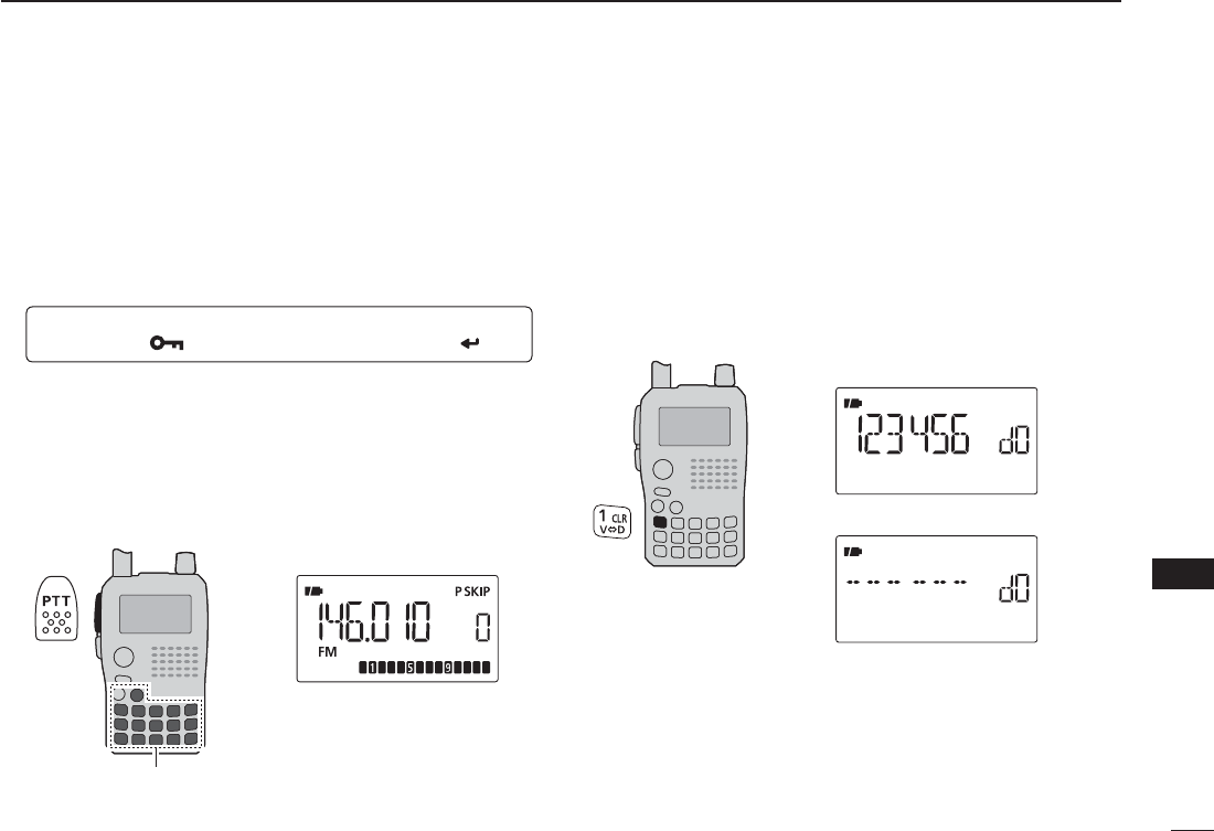
N Clearing a DTMF memory
An unwanted DTMF memory can be cleared (erased).
q Push and hold [DTMF.M](0) for 1 sec. to enter DTMF
memory mode.
w Push [](2) or [](8) to select the desired DTMF mem-
ory channel to be cleared.
e Push and hold [CLR](1) for 1 sec. to clear the selected
DTMF memory channel.
After clearing the DTMF memory.
When entering DTMF programming mode.
r Push [V/MHz] to exit DTMF memory.
144
13 OTHER FUNCTIONS
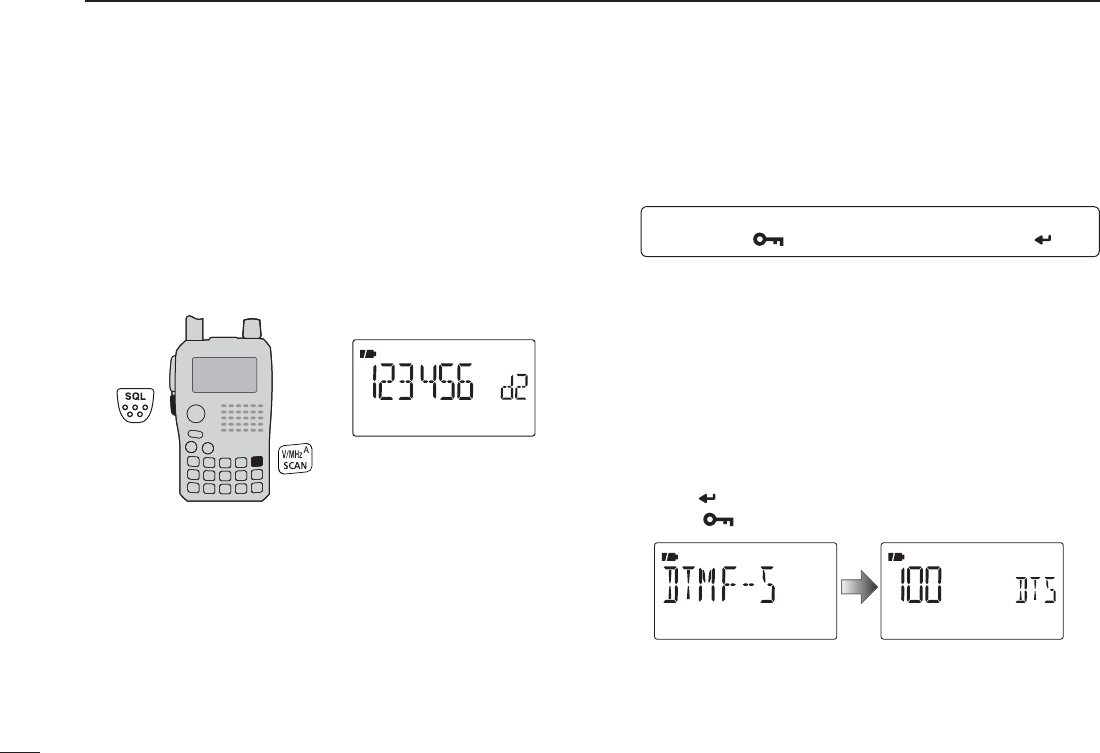
N Confirming a DTMF memory
A DTMF memory can be confirmed with a DTMF tone.
q Push and hold [DTMF.M](0) for 1 sec. to enter DTMF
memory mode.
w Push [](2) or [](8) to select the desired DTMF memory
channel.
ePush [SQL] to confirm the DTMF memory contents.
r Push [V/MHz] to exit DTMF memory.
N Setting DTMF transfer speed
The DTMF transfer speed can be selected.
q Enter “DTMF-S” in DUP.T set mode.
MENU ¶ DUP.T ¶DTMF-S
(p. 119)
(Push [MENU ]), (Push [](2)/[](8), then push [ ](5).)
w Push [](2) or [](8) to select DTMF transfer speed as
below.
100 : Transfer the DTMF tones at about 100 msec. per
tone.
200 : Transfer the DTMF tones at about 200 msec per
tone.
300 : Transfer the DTMF tones at about 300 msec per
tone.
500 : Transfer the DTMF tones at about 500 msec per
tone.
e Push [](5) to return to DUP.T set mode, and push
[MENU ] to return to frequency indication.
145
13
OTHER FUNCTIONS
1
2
3
4
5
6
7
8
9
10
11
12
13
14
15
16
17
18
19
DSubaudible (repeater) tone
Some repeaters require subaudible tones to be accessed.
Subaudible tones are superimposed over your normal signal
and must be set in advance.
DTone and DTCS squelches
The tone squelch (CTCSS) or DTCS squelch opens only
when receiving a signal containing a matching subaudible
tone or DTCS code, respectively. You can silently wait for calls
from group members using the same tone or code. Separate
tone frequencies can be set for repeater and tone squelch/
pocket beep operation.
DReverse tone/DTCS squelch
The reverse tone/DTCS squelch is convenient if you want to
ignore a specific signal. The transceiver mutes the squelch
when a signal with the matched tone or code is received.
“T SQL-R” / “DTCS-R” is displayed when the reverse tone/
DTCS squelch is set.
DPocket beep
These functions use subaudible tones or DTCS codes for
calling and can be used as a “common pager” to inform
you that someone has called while you were away from the
transceiver.
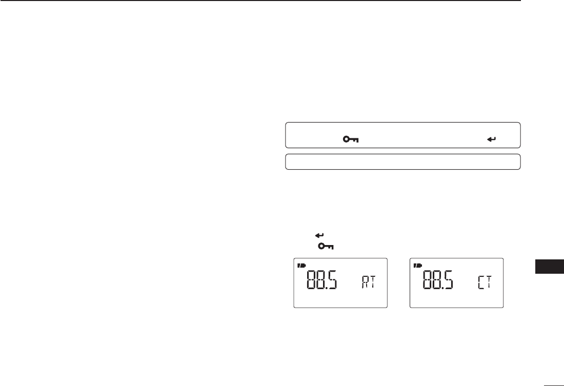
D
Setting subaudible tones for repeater or tone
squelch
q Enter “R TONE or C TONE” in DUP.T set mode.
MENU ¶ DUP.T ¶R TONE (p. 117)
(Push [MENU ]), (Push [](2)/[](8), then push [ ](5).)
MENU ¶ DUP.T ¶C TONE (p. 117)
w Push [](2) or [](8) to select the desired repeater or
CTCSS tone frequency.
• Each operating band and each memory channel have indepen-
dent settings.
• See page 117 for available tone frequencies for details.
e Push [ ](5) to return to DUP.T set mode, and push
[MENU ] to return to frequency indication.
Repeater tone setting CTCSS tone setting
NTone frequency and DTCS code
146
13 OTHER FUNCTIONS
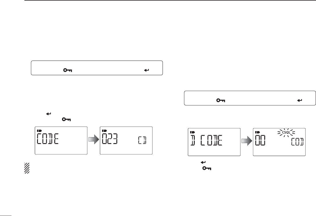
NTone frequency and DTCS code (Continued)
DSetting DTCS code for DTCS squelch or beep
q Enter “CODE” (DTCS CODE) in DUP.T set mode.
MENU ¶ DUP.T ¶CODE
(p. 118)
(Push [MENU ]), (Push [](2)/[](8), then push [ ](5).)
w Push [](2) or [](8) to select the desired DTCS tone
code.
• Each operating band and each memory channel have indepen-
dent settings.
• See page 118 for available DTCS codes for details.
e Push [ ](5) (or [](4)) to return to DUP.T set mode, and
push [MENU ] to return to frequency indication.
DTCS phase can be selected in “DTCS-P” (DTCS PO-
LARITY) item. (p. 118)
NDigital code and digital call
sign setting
D
Setting digital code
for digital code squelch
or beep
q Push and hold [MODE](BAND) for 1 sec. several times to
select DV mode.
w Enter “D CODE” (DIGITAL CODE) in DUP.T set mode.
MENU ¶ DUP.T ¶D CODE
(p. 118)
(Push [MENU ]), (Push [](2)/[](8), then push [ ](5).)
e Push [](2) or [](8) to select the desired digital code.
• Each operating band and each memory channel have indepen-
dent settings.
r Push [ ](5) to return to DUP.T set mode, and push
[MENU ] to return to frequency indication.
147
13
OTHER FUNCTIONS
1
2
3
4
5
6
7
8
9
10
11
12
13
14
15
16
17
18
19
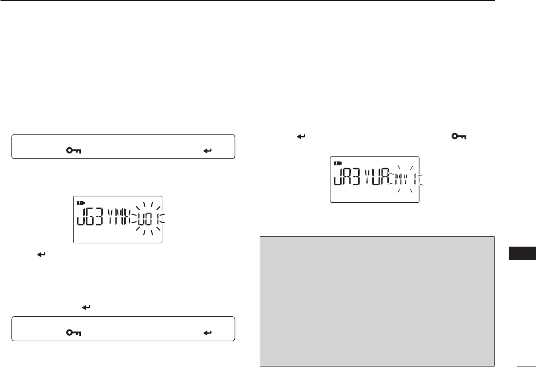
DSetting the YOUR and MY call signs for
digital call sign squelch or beep
q Push and hold [MODE](BAND) for 1 sec. several times to
select DV mode.
w Enter “UR” in CALL-S set mode.
MENU ¶ CALL-S ¶UR
(p. 37)
(Push [MENU ]), (Push [](2)/[](8), then push [ ](5).)
e Push [](2) or [](8) to select the desired call sign.
• Input the call sign if the desired call sign is not stored in the
transceiver. See p. 37 for detail.
r Push [ ](5) to specify the call sign and then push [](4)
to return to CALL-S set mode.
• Push [](4) to return to CALL-S set mode without storing call
sign.
t Push [](2) three times to select “MY” in CALL-S set
mode, then push [](5) to enter “MY” setting.
MENU ¶ CALL-S ¶MY
(p. 36)
(Push [MENU ]), (Push [](2)/[](8), then push [ ](5).)
y Push [](2) or [](8) to select the desired call sign.
• Input the call sign if the desired call sign is not stored in the
transceiver. See p. 36 for detail.
u Push [ ](5) to set call sign and push [MENU ] to re-
turn to frequency indication.
CAUTION!: Use digital code squelch when operating with
more than 3 stations. Because the digital call sign squelch
function recognizes “MY” (MY CALL SIGN) the digital call
sign squelch function can be used when operating with only
one station.
NOTE:
• The tone/DTCS code squelch opens sometimes when
other stations communicate with adjacent tone frequency
or DTCS code.
• No audio sounds with S-meter swaying when receiving
signal except my call sign on DV mode .
148
13 OTHER FUNCTIONS
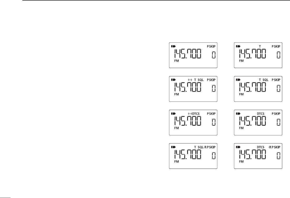
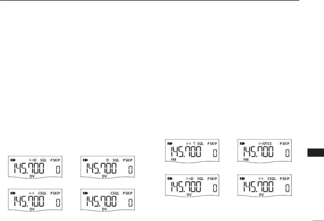
N Tone/DTCS squelch
q Set the desired operating frequency on FM or FM-N
mode, CTCSS tone and DTCS code.
w Push and hold [TONE](7) for 1 sec. several times to acti-
vate the tone or DTCS squelch. (T SQL or DTCS)
• Subaudible tone encoder “T,” pocket beep (tone squelch)
“ST SQL,” tone squelch “T SQL,” DTCS beep “SDTCS,”
DTCS squelch “DTCS,” tone squelch reverse “T SQL-R,” DTCS
squelch reverse “DTCS-R” and no tone operation are activated
in order.
• Rotating [DIAL] while pushing [TONE](7) also selects the tone
functions.
e Operate the transceiver in the normal way.
r When the received signal includes a matching tone/code,
the squelch opens and the signal can be heard.
• When the received signal’s tone/code does not match, tone/
DTCS squelch does not open, however, the S-indicator shows
signal strength.
• To open the squelch manually, push and hold [SQL].
No tone operation Subaudible tone encoder
Tone squelchPocket beep
DTCS beep DTCS squelch
Tone squelch (reverse) DTCS squelch (reverse)
149
13
OTHER FUNCTIONS
1
2
3
4
5
6
7
8
9
10
11
12
13
14
15
16
17
18
19
NDigital squelch
q Set the desired operating frequency on DV mode, Digital
code and “MY” (MY CALL SIGN).
w Push and hold [DSQ](7) for 1 sec. several times to acti-
vate the digital call sign or digital code squelch.
• Digital call sign beep “DSQLS,” Digital call sign squelch
“DSQL,” Digital code beep “CSQLS,” Digital code squelch
“CSQL,” and no digital squelch operation are activated in order.
• Rotating [DIAL] while pushing [DSQ](7) also selects the digital
squelch functions.
e Operate the transceiver in the normal way.
r When the received signal includes a matching call sign/
code, the squelch opens and the signal can be heard.
• When the received signal’s call sign/code does not match, digi-
tal call sign/digital code squelch does not open, however, the
S-indicator shows signal strength.
• To open the squelch manually, push and hold [SQL].
Digital call sign squelchDigital call sign pocket beep
Digital code pocket beep Digital code squelch
N Pocket beep function
qSet the desired operating frequency.
w Set the desired CTCSS tone, DTCS code, Digital call sign
or Digital code.
e Push and hold [TONE](7) or [DSQ](7) for 1 sec. several
times to activate the pocket beep, DTCS beep, Dig-
ital call sign beep or Digital code beep. (“ST SQL,”
“SDTCS,” “SD SQL” or “SCSQL”)
• Rotating [DIAL] while pushing [TONE](7)/[DSQ](7) also selects
the tone squelch or digital squelch functions.
r When a signal with the correct tone, code, digital call sign
or digital code is received, the transceiver emits beep
tones for 30 sec. and blinks “S.”
t Push [PTT] to answer or push [SQL] to stop the beeps
and blinking.
Pocket beep
Digital call sign pocket beep Digital code pocket beep
DTCS beep
150
13 OTHER FUNCTIONS
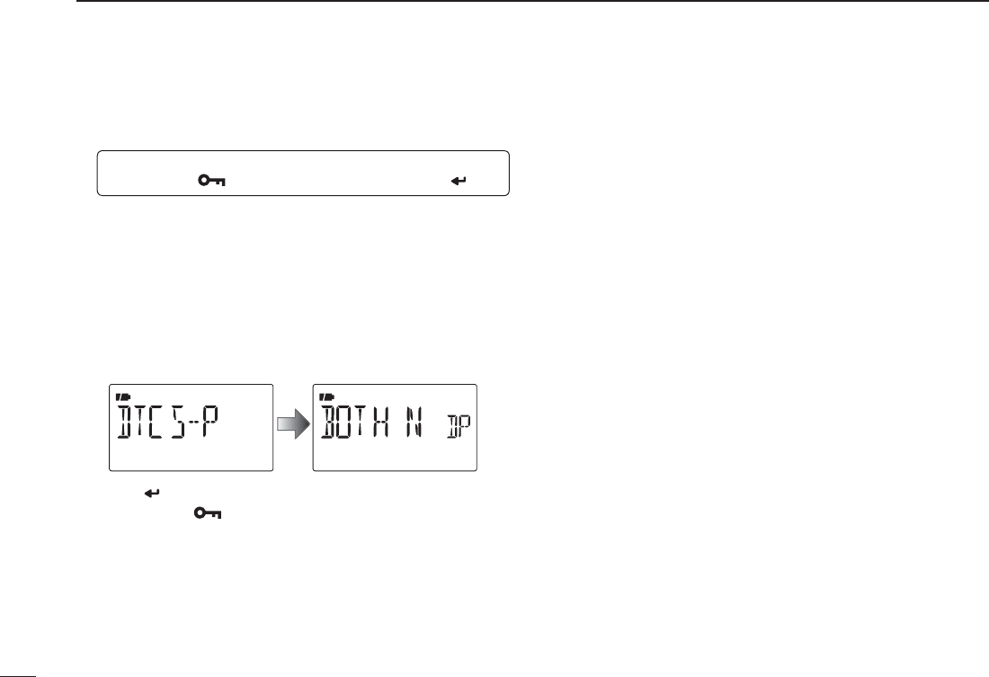
NDTCS polarity setting
q Enter “DTCS-P” in DUP.T set mode.
MENU ¶ DUP.T ¶DTCS-P
(p. 118)
(Push [MENU ]), (Push [](2)/[](8), then push [ ](5).)
w Push [](2) or [](8) to select the desired DTCS polarity
mode.
• BOTH N : Normal phase is used for both TX and RX.
(Default)
• TN-RR : Normal phase is used for TX; Reverse phase
for RX.
• TR-RN : Reverse phase is used for TX; Normal phase
for RX.
• BOTH R : Reverse phase is used for both TX and RX.
e Push [ ](5) (or [](4)) to return to DUP.T set mode, and
push [MENU ] to return to frequency indication.
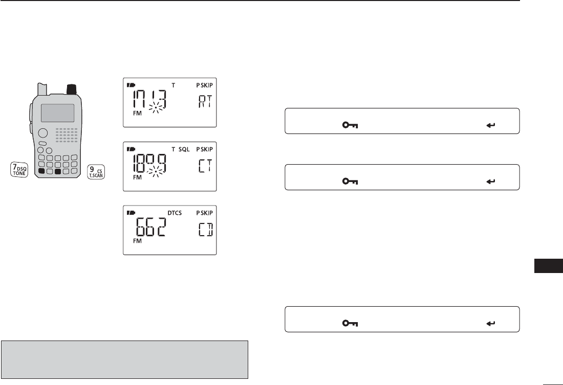
N Tone scan
The transceiver can detect the subaudible tone frequency
and DTCS code in a received signal. By monitoring a signal
that is being transmitted on a repeater input frequency, you
can determine the tone frequency required to access the re-
peater.
q Set the desired frequency on FM/FM-N mode or memory
channel to be checked for a tone frequency or DTCS
code.
w Push and hold [TONE](7) for 1 sec. several times to acti-
vate the repeater tone, tone squelch or DTCS squelch. (T,
T SQL or DTCS)
• Rotating [DIAL] while pushing and holding [TONE](7) also se-
lects the tone functions.
e Push and hold [T.SCAN](9) for 1 sec. to start the tone
scan.
• To change the scanning direction, rotate [DIAL].
r When the tone frequency or DTCS code is decoded, the
set mode contents are programmed with the frequency or
code.
• The tone scan pauses for the set period in scan pause timer
(p. 119) when a tone frequency or DTCS code is detected.
• The decoded tone frequency is used for the repeater tone fre-
quency when the tone squelch is OFF.
• The decoded tone frequency is used for the tone squelch fre-
quency when the tone squelch is ON.
• The decoded DTCS code is used for the DTCS squelch code
when the DTCS squelch is ON.
151
13
OTHER FUNCTIONS
1
2
3
4
5
6
7
8
9
10
11
12
13
14
15
16
17
18
19
[DIAL]
Tone scan for repeater tone
Tone scan for tone squelch
Tone scan for DTCS squelch
tPush [V/MHz] to stop the scan.
• If the scan is cancelled before the transceiver detects the tone
or code, the set mode contents are not changed.
• The detected tone is used for temporary operation only. The
stored tone setting in memory or call channel won’t be changed.
NOTE: Tone frequency is over-written automatically when it cor-
responds with the scanning tone frequency in tone squelch mode.
However, it is not over-written in memory or call channel mode.
N Beep tones
You can select to have confirmation beeps sound at the
push of a switch. The output level can be adjusted within 39
levels with “BEEPLV” in SOUNDS set mode.
MENU ¶ SOUNDS ¶BEEPLV
(p. 128)
(Push [MENU ]), (Push [](2)/[](8), then push [ ](5).)
You can select silent operation by turning beep tones OFF
with “KEY B” in SOUNDS set mode.
MENU ¶ SOUNDS ¶KEY B
(p. 128)
(Push [MENU ]), (Push [](2)/[](8), then push [ ](5).)
N Dial speed acceleration
The dial speed acceleration automatically speeds up the
tuning dial speed when rotating [DIAL] rapidly.
This function can be turned ON and OFF with “DIAL S”
(DIAL SPEED) in FUNC set mode (SET).
MENU ¶ SET ¶FUNC ¶DIAL S
(p. 125)
(Push [MENU ]), (Push [](2)/[](8), then push [ ](5).)
152
13 OTHER FUNCTIONS
N Key lock effect
While the lock function is ON, [PWR],[]/[],[SQL] and
[PTT] can still be accessed. Accessible switches can be set
to one of 4 groups with “LOCK” in FUNC set mode (SET).
MENU ¶ SET ¶ FUNC ¶LOCK
(p. 125)
(Push [MENU ]), (Push [](2)/[](8), then push [ ](5).)
• “NORM”: [PWR],[]/[],[SQL] and [PTT] are accessible.
• “NO S” : [PWR],[SQL] and [PTT] are accessible.
• “NO V” : [PWR],[]/[], and and [PTT] are accessible.
• “ALL” : [PWR] and [PTT] are accessible.
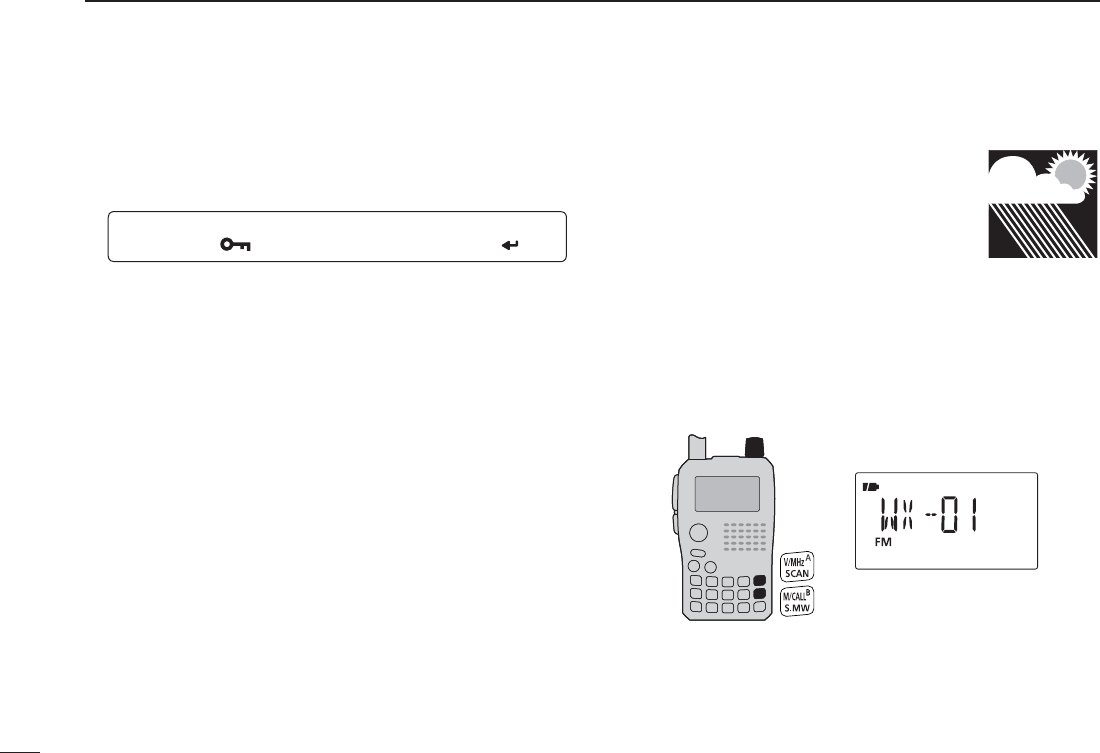
NWeather channel operation
There are 10 weather channels for moni-
toring weather channels from the NOAA
(National Oceanographic and Atmospheric
Administration) broadcasts.
D Weather channel selection
q Push [M/CALL] several times to select weather channel
mode.
• “WX” and the weather channel number appear.
wRotate [DIAL] to select the desired weather channel.
e Push [V/MHz] or [M/CALL] to return to the previous fre-
quency or memory channel.
[DIAL] Weather channel indication
153
13
OTHER FUNCTIONS
1
2
3
4
5
6
7
8
9
10
11
12
13
14
15
16
17
18
19
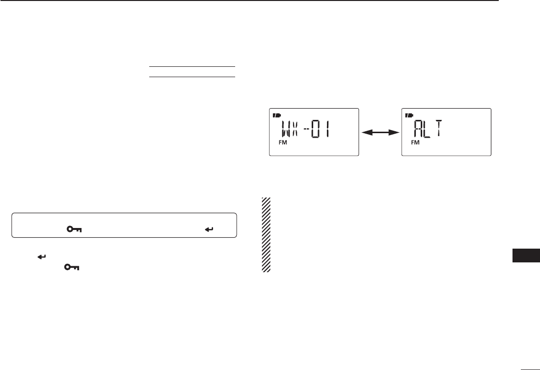
D Weather alert function U.S.A. version only
NOAA broadcast stations transmit weather alert tones be-
fore important weather announcements. When the weather
alert function is turned ON, the selected weather channel
is monitored every 5 sec. for the announcement. When the
alert signal is detected, the “ALT” and the WX channel indica-
tions are displayed alternately and sounds a beep tone until
the transceiver is operated. The previously selected (used)
weather channel is checked periodically during standby or
while scanning.
qSelect the desired weather channel.
w Enter “WX-ALT” in SCAN set mode.
MENU ¶ SCAN ¶WX-ALT
(p. 120)
(Push [MENU ]), (Push [](2)/[](8), then push [ ](5).)
e Push [](2) or [](8) to select “ON” or “OFF.”
r Push [](5) (or [](4)) to return to SCAN set mode, and
push [MENU ] to return to the weather channel indica-
tion.
tSet the desired stand-by condition.
• Select VFO, memory or call channel.
• Scan or priority watch operation can also be selected.
y When the alert is detected, a beep sounds and the follow-
ing indication will be displayed.
Shows above indications alternately.
uTurn the weather alert function OFF in Scan menu.
NOTE: While receiving a signal (on a frequency other
than the weather alert ON frequency), the receiving signal
or audio will be interrupted momentarily every 5 sec. (ap-
prox.) in the case that the alert function is turned ON. This
symptom is caused by the WX alert function. To cancel
these symptoms, set the weather alert item OFF in set
mode.
154
13 OTHER FUNCTIONS
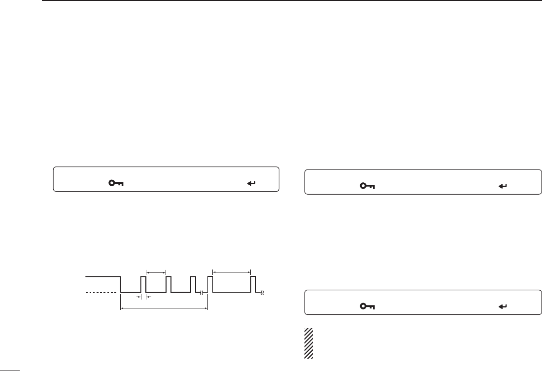
N Power save
The power save function reduces the current drain to con-
serve battery power.
The power save duty cycle, the ratio of receive circuit on
to receive circuit off during standby, can be set to auto-
matic1 (default), 1 : 4 (150 msec. : 600msec.), 1 : 8 (150 msec.
: 1200msec.), automatic2, in addition stopping the operation
of a digital block at the DV mode, or OFF with “P SAVE” in
FUNC set mode (SET).
MENU ¶ SET ¶ FUNC ¶P SAVE
(p. 123)
(Push [MENU ]), (Push [](2)/[](8), then push [ ](5).)
• “AUTO1” selects “1:4” duty ratio when receiving no signal for 5
sec., then “1:8” 60 sec. after that.
• “AUTO2”
suppresses the consumption of the battery by stopping
the operation of a digital block of the DV mode in addition to the op-
eration of AUTO1.
150 msec.
60 sec.
600 msec. 1200 msec.
No signal
5 sec.
Circuit ON
Circuit OFF
N Auto power OFF
The transceiver can be set to automatically turn OFF after a
specified period with a beep when no switch is pushed.
120 min., 90 min., 60 min., 30 min. and OFF can be specified.
The specified period is retained even when the transceiver
is turned OFF by the auto power-off function. To cancel the
function, select “OFF” in the auto power-off item in set mode.
This can be selected with “AP OFF” in FUNC set mode
(SET).
MENU ¶ SET ¶ FUNC ¶AP OFF
(p. 126)
(Push [MENU ]), (Push [](2)/[](8), then push [ ](5).)
N Auto power ON
The transceiver can be set to automatically turn ON after a
specified period. The timer can be selected within 30 min. to
24 hrs. in 30 min. steps.
This can be selected with “AP ON” in FUNC set mode (SET).
MENU ¶ SET ¶ FUNC ¶AP ON
(p. 126)
(Push [MENU ]), (Push [](2)/[](8), then push [ ](5).)
When operating with battery pack or case and the battery
is exhausted, auto power-on does not function.
During standby, a small current still flows in the radio.
155
13
OTHER FUNCTIONS
1
2
3
4
5
6
7
8
9
10
11
12
13
14
15
16
17
18
19
N Time-out timer
To prevent accidental prolonged transmission, etc.,
the transceiver has a time-out timer. This timer cuts a
transmission OFF after 1, 3, 5 or 10 min. of continuous
transmission. This timer can be cancelled (default).
Approx. 10 sec. before the time-out timer is activated, the
transceiver emits a beep tone as a warning.
This can be selected with “TOT” in FUNC set mode (SET).
MENU ¶ SET ¶ FUNC ¶TOT
(p. 124)
(Push [MENU ]), (Push [](2)/[](8), then push [ ](5).)
N PTT lock
To prevent accidental transmission, etc., the transceiver has
a PTT lock function.
This can be selected with “PTT LK” in FUNC set mode
(SET).
MENU ¶ SET ¶ FUNC ¶PTT LK
(p. 123)
(Push [MENU ]), (Push [](2)/[](8), then push [ ](5).)
N Display backlighting
The transceiver has display backlighting with a 5 sec. timer for
night time operation. The display backlighting can be turned
ON continuously, turned AUTO or turned OFF, if desired.
MENU ¶ SET ¶ DISP ¶LIGHT
(p. 127)
(Push [MENU ]), (Push [](2)/[](8), then push [ ](5).)
N LCD contrast
The contrast of the LCD can be selected from 4 levels.
MENU ¶ SET ¶ DISP ¶CONT
(p. 127)
(Push [MENU ]), (Push [](2)/[](8), then push [ ](5).)
156
13 OTHER FUNCTIONS
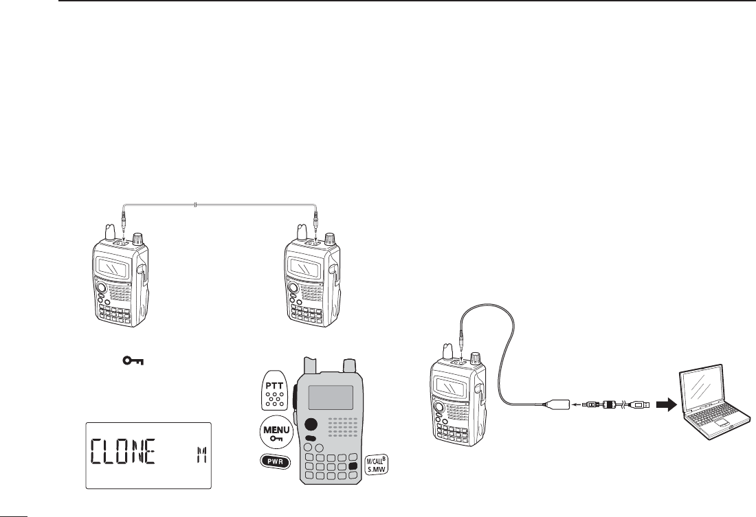
N Cloning function
The IC-80AD has transceiver-to-transceiver data cloning
capability. This function is useful when you want to copy all
of the programmed contents from one IC-80AD to another.
• An optional OPC-474 CLONING CABLE is required.
q Turn the transceiver’s power OFF, then connect an optional
OPC-474 between both [SP] jacks.
OPC-474
to the [SP] jack
w While pushing [M/CALL] and
[MENU ], push and hold
[PWR] for 1 sec. to enter clon-
ing mode.
• “CLONE M” appears.
ePush [PTT] on the “master” transceiver.
• “CL OUT M” appears and the bar meter shows that cloning is
taking place.
• After the cloning is completed, the display returns to “CLONE
M.”
rPush and hold [PWR] for 1 sec. to turn power OFF.
The CS-80/880 CLONING SOFTWARE (free download ) is
also available to clone/edit contents with a PC (for Microsoft
® Windows® 2000/XP or Windows VistaTM) and using ICF for-
mat files.
to [SP]
jack
PC
OPC-478UC
(USB type) to USB port
157
1
2
3
4
5
6
7
8
9
10
11
12
13
14
15
16
17
18
19
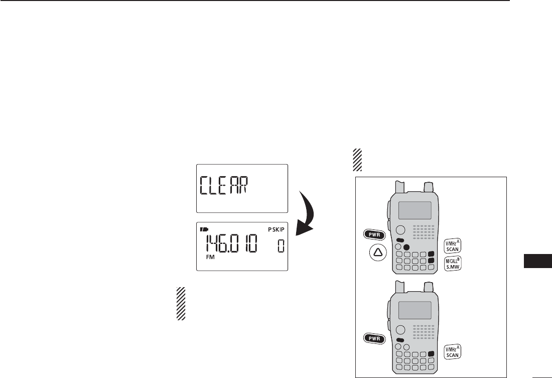
N Resetting
The display may occasionally display
erroneous information (e.g. when first
applying power). This may be caused
externally by static electricity or by
other factors.
If this problem occurs, turn power OFF.
After waiting a few seconds, turn power
ON again. If the problem persists, per-
form either or both procedures below.
• All reset
Reset the CPU before operating the
transceiver for the first time, or if the
internal CPU malfunctions, to clear and
return all programmed contents to their
default settings.
• Partial reset
If you want to initialize the operat-
ing conditions (VFO frequency, VFO
settings, set mode contents) without
clearing the memory contents, a partial
reset function is available for the trans-
ceiver.
D All reset
q Push and hold [PWR] for 1 sec. to
turn power OFF.
w While pushing and holding [V/MHz],
[M/CALL] and [], then turn power
ON to reset the CPU.
• “CLEAR” appears when resetting the
CPU (See the illustration below).
CAUTION: Resetting the CPU re-
turns all programmed contents to
their default settings.
D Partial reset
q Push and hold [PWR] for 1 sec. to
turn power OFF.
w While pushing and holding [V/MHz],
then turn power ON to partially
reset the transceiver.
NOTE: No message appears on the
display after the partial reset is done.
All reset
Partial reset
13
OTHER FUNCTIONS

158
TROUBLESHOOTING
14
PROBLEM
No power comes ON.
No sound comes from the
speaker.
Transmitting is impossible.
No contact possible with
another station.
Frequency can not be set.
Program scan function can
not start.
Memory scan function can
not start.
The displayed frequency is
erroneous.
Can not charge the battery
with BC-139 (LED blinks
orange).
If your transceiver seems to be malfunctioning, please check the following points before sending it to a service center.
POSSIBLE CAUSE
• The batteries are exhausted.
• Loose connection of a battery pack (case).
• The battery polarity is reversed.
• Volume level is too low.
• External speaker is connected or cloning
cable is inserted.
• The batteries are exhausted.
• A frequency outside of the 144/440 MHz
amateur bands is set.
• Different tone is selected with tone/DTCS
squelch.
• The lock function is activated.
•
Memory mode or call channel is selected.
•
Memory mode or call channel is selected.
• Same frequencies are programmed both
“1A” and “1B” of PROGRAM-CH.
• VFO mode or call channel is selected.
•
The programmed memory channel is only one.
• The CPU malfunctioned.
• External factors caused a fault.
• The transceiver's power is ON.
• The battery pack is fault electric dis-
charge.
SOLUTION
• Replace the batteries or charge the battery pack.
• Clean battery terminals.
• Check the battery polarity.
• Push [] or [] to suitable level.
• Check the connection of the external speaker cor-
rectly or remove the cloning cable.
• Replace the batteries or charge the battery pack.
• Reset the frequency within 144/440 MHz amateur
bands.
• Check the tone/DTCS using tone scan.
•
Push [MENU ] for 1 sec. to cancel the function.
• Push [V/MHz] to set VFO mode.
• Push [V/MHz] to set VFO mode.
• Programming different frequencies in “1A” and “1B”
respectively.
• Push [M/CALL] to set memory mode.
• Program 2 or more memory channels.
• Reset the transceiver.
• Remove and re-attach the battery pack or battery
case.
• Turn the transceiver’s power OFF, or insert only the
battery pack into the BC-139 to charge it.
• The battery pack is charged alone (without the trans-
ceiver) or regular charge is carried out.
REF.
pgs. 2, 12–14
p. 14
p. 14
p. 16
–
pgs. 2, 12–14
pgs. 20, 159
p. 150
p. 24
p. 18
p. 18
p. 103
p. 18
p. 92
p. 157
p. 2
p. 13
pgs. 12, 13
159
1
2
3
4
5
6
7
8
9
10
11
12
13
14
15
16
17
18
19
D General
• Frequency coverage : (unit: MHz)
Version TX RX
U.S.A. 144–148, 420–450*10.495–823.990,
849–868.990,
894–999.990
S.E.A.
CHN
EXP
137–174*2, 400–470*20.495–999.990
KOR 144–146, 430–440 144–146, 430–440
AUS 144–148, 420–450*20.495–999.990
*1Guaranteed 440–450 MHz only, *2Guaranteed 430–440 MHz only
• Mode :
FM, FN-N, AM (Rx only), WFM (Rx only), DV
• No. of memory channels : 1052
(incl. 50 scan edges and 2 call channels)
• Usable temp. range : –20°C to +60°C; –4°F to +140°F
• Tuning steps : 5‡, 6.25‡, 8.33‡, 9‡, 10, 12.5, 15‡, 20,
25, 30, 50, 100, 125 and 200 kHz
• Frequency stability : ±2.5 ppm
(–20°C to +60°C; –4°F to +140°F)
• Power supply : 10.0–16.0 V DC for external DC power,
or specified Icom battery pack
• Digital transmission speed: 4.8 kbps
• Voice coding speed : 2.4 kbps
• Current drain (at 7.4 V DC) :
Tx High 144 MHz 1.8 A typical
430/440 MHz 2.1 A typical
Tx Mid. 144 MHz 1.2 A typical
430/440 MHz 1.5 A typical
Tx Low 144 MHz 0.6 A typical
430/440 MHz 0.7 A typical
Tx S-Low 144 MHz 0.4 A typical
430/440 MHz 0.4 A typical
Rx Rated output 170 mA typical (FM)
215 mA typical (DV)
Power save 30 mA typical (FM)
(Duty 1:4) 38 mA typical (DV)
standby 62 mA typical (FM)
106 mA typical (DV)
• Antenna connector : SMA (50 Ω)
• Dimensions : 58.4(W)×103(H)×34.2(D) mm;
(projections not included) 2
5⁄16(W)×41⁄16(H)×111⁄32(D) in
• Weight (approx.) : 290 g; 10.3 oz (with antenna and BP-217)
D Transmitter
• Modulation system :
FM Variable reactance freq. modulation
DV (Digital) GMSK digital modulation
• Output power (at 7.4 V DC)
(Typical) : High 5.0 W, Mid. 2.5 W, Low 0.5 W,
S-Low 0.1 W
• Max. frequency deviation : ±5.0 kHz (FM wide: approx.)
±2.5 kHz (FM narrow: approx.)
• Spurious emissions : Less than –60 dBc at High/Mid.
Less than –13 dBm at Low/Slow
• Ext. mic. impedance : 2 kΩ
‡Selectable depending on the operating frequency band.
15
SPECIFICATIONS

160
D Receiver
• Receive system :
Except WFM Double-conversion superheterodyne
WFM Triple-conversion superheterodyne
• Intermediate frequencies :
1st 61.65 MHz/59.25 MHz (WFM only)
2nd 450 kHz/13.35 MHz (WFM only)
3rd 1.95 MHz (WFM only)
• Sensitivity (except spurious points):
FM (1 kHz/3.5 kHz Dev.; 12 dB SINAD)
1.625–29.995 MHz 0.4 µV typ.
30.000–75.995 MHz 0.25 µV typ.
76.000–117.995 MHz 0.25 µV typ.
118.000–173.995 MHz 0.14 µV typ.
174.000–259.995 MHz 0.32 µV typ.
260.000–349.995 MHz 0.32 µV typ.
350.000–469.995 MHz 0.16 µV typ.
470.000–599.995 MHz 0.32 µV typ.
600.000–999.990 MHz 0.56 µV typ.
WFM (1 kHz/52.5 kHz Dev.; 12 dB SINAD)
76.000–108.000 MHz 1 µV typ.
175.000–221.995 MHz 1.8 µV typ.
470.000–770.000 MHz 2.5 µV typ.
AM (1 kHz/30% Mod.; 10 dB S/N)
0.495–4.995 MHz 1.3 µV typ.
5.000–29.995 MHz 0.56 µV typ.
118.000–137.000 MHz 0.5 µV typ.
222.000–246.995 MHz 0.79 µV typ.
247.000–329.995 MHz 1 µV typ.
DV (PN9/GMSK 4.8 kbps; BER 1%)
VHF (Amateur band only) 0.22 µV typ.
UHF (Amateur band only) 0.22 µV typ.
• Audio output power : More than 300 mW at 10% distortion
(at 7.4 V DC) with an 8 Ω load
• Selectivity :
FM (Wide), AM More than 50 dB
FM (Narrow), DV More than 45 dB
WFM More than 300 kHz/–3 dB
Less than 700 kHz/–20 dB
• Ext. speaker connector : 3-conductor 3.5(d) mm; (1⁄8˝)/8 Ω
• Spurious and image rejection ratio :
VHF More than 60 dB
UHF More than 50 dB
(Intermediate freq.; More than 60 dB)
• Squelch Sensitivity (except spurious points):
FM (1 kHz/3.5 kHz Dev.)
1.625–29.995 MHz 0.4 µV typ.
30.000–75.995 MHz 0.25 µV typ.
76.000–117.995 MHz 0.25 µV typ.
118.000–173.995 MHz 0.14 µV typ.
174.000–259.995 MHz 0.32 µV typ.
260.000–349.995 MHz 0.32 µV typ.
350.000–469.995 MHz 0.16 µV typ.
470.000–599.995 MHz 0.32 µV typ.
600.000–999.990 MHz 0.56 µV typ.
WFM (1 kHz/52.5 kHz Dev.)
76.000–108.000 MHz 1 µV typ.
175.000–221.995 MHz 1.8 µV typ.
470.000–770.000 MHz 2.5 µV typ.
AM (1 kHz/30% Mod.)
0.495–4.995 MHz 1.3 µV typ.
5.000–29.995 MHz 0.56 µV typ.
118.000–137.000 MHz 0.5 µV typ.
222.000–246.995 MHz 0.79 µV typ.
247.000–329.995 MHz 1 µV typ.
15 SPECIFICATIONS

161
1
2
3
4
5
6
7
8
9
10
11
12
13
14
15
16
17
18
19
D Battery pack and charger
• BP-216 BATTERY CASE
Battery case for LR6 (AA) × 2 alkaline batteries.
• BP-217 LI-ION BATTERY PACK
7.4 V/1300 mAh (Min.)/1580 mAh (Typ.) Lithium Ion battery
pack. Battery life: 6.7 hrs. (approx.; VHF, FM, high power,
Tx : Rx : Standby = 1:1:8)
• BC-167SA/SC/SV BATTERY CHARGER
For regular charging of battery packs. Charging time : Max.
6 hrs.
• BC-139 DESKTOP CHARGER+BC-123 AC ADAPTER
Rapidly charges BP-217 LI-ION BATTERY PACK in approx. 2.5
hrs.
D Microphones
• HM-189GPS GPS SPEAKER-MICROPHONE
Allows you to operate in rainy condition; includes GPS re-
ceiver and antenna.
• HM-75A REMOTE CONTROL SPEAKER MICROPHONE
Allows you to remotely select operating channels, etc.
• HM-131 SPEAKER-MICROPHONE
For operation while conveniently hanging the transceiver
from your belt, etc.
• HM-153/HM-166 EARPHONE-MICROPHONE
Ideal for hands-free operation by clipping the microphone
with the PTT switch to your lapel or breast pocket.
Allows you to operate in rainly condition.
•HS-85 HEADSET WITH VOX/PTT UNIT
Hands-free headset with VOX control box.
•SP-13 EARPHONE
Provides clear audio in noisy environments.
D Other options
•CP-12L
CIGARETTE LIGHTER CABLE WITH NOISE FILTER
•CP-19R
CIGARETTE LIGHTER CABLE WITH DC-DC CONVERTER
Allows you to operate the transceiver through a 12 V ciga-
rette lighter socket. You can also charge the attached bat-
tery pack (during stand-by only).
CP-19R: A built-in DC-DC converter provides an 11 V DC
output.
•OPC-254L DC POWER CABLE
For operation and charging via an external power supply.
•OPC-474 CLONING CABLE
Used for handheld-to-handheld cloning.
•OPC-478UC CLONING CABLE
Used for data cloning between transceiver and PC with
CS-80/880 (free download software).
• OPC-1529R DATA COMMUNICATION CABLE
Allows GPS operation in DV mode.
•LC-163 CARRYING CASE
Helps protect the transceiver from scratches, etc.
• AD-92SMA ANTENNA CONNECTOR ADAPTER
Allows you to connect an external antenna with a BNC con-
nector.
• CS-80/880 CLONING SOFTWARE (free download )
Use this software to program settings such as memory
channels and set mode contents quickly and easily via your
PC’s USB port. OPC-478UC is required.
16
OPTIONS
162
16 OPTIONS
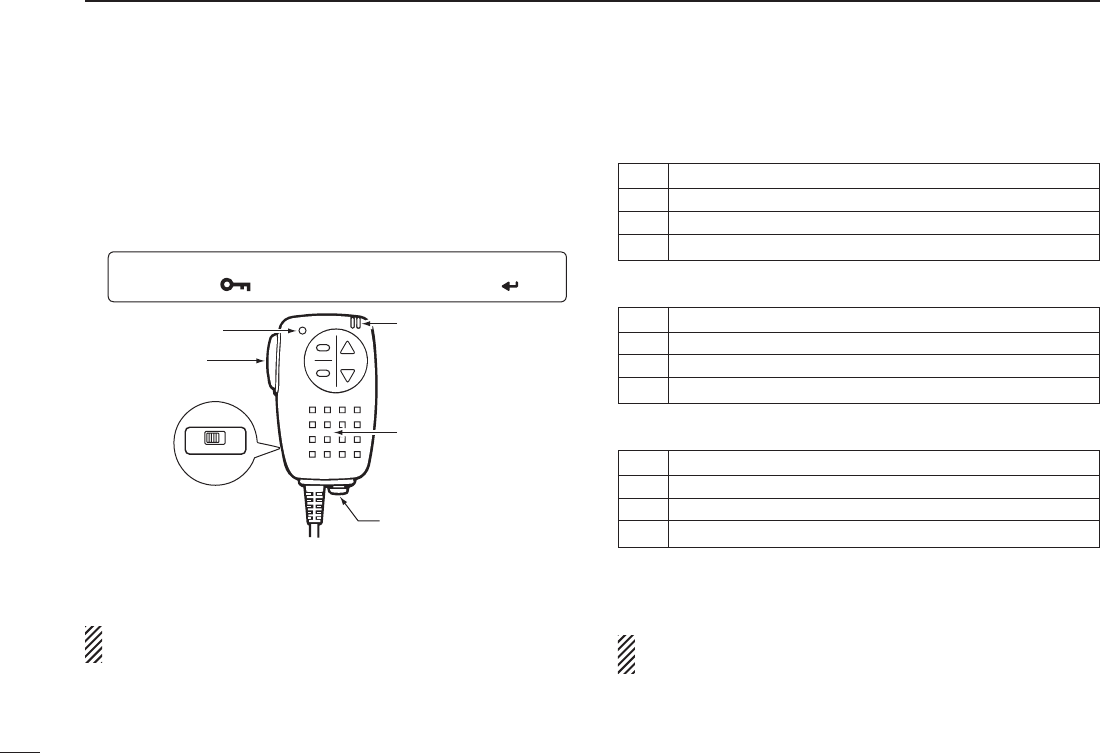
The optional HM-75A allows you to remotely select operat-
ing frequencies, memory channels, etc.
Remote control functions can be selected from 3 settings.
These can be selected with “MIC” in FUNC set mode (SET).
MENU ¶ SET ¶ FUNC ¶MIC
(p. 126)
(Push [MENU ]), (Push [](2)/[](8), then push [ ](5).)
A
B
Speaker
Earphone jack
PTT switch
OFF ON
LOCK
Transmit LED Microphone
The HM-75A has a lock switch on the backside to prevent
accidental frequency changes, etc.
Be sure to turn power OFF when plugging/unplugging the
HM-75A to/from the [SP/MIC] jack.
• NORM-1: (default)
[A] Selects band.
[B] Toggles VFO mode and memory mode.
[Y]F
requency or memory channel “UP.”
[Z]F
requency or memory channel “DOWN.”
• NORM-2:
[A] Toggles the monitor function.
[B] Toggles VFO mode and memory mode.
[Y]F
requency or memory channel “UP.”
[Z]F
requency or memory channel “DOWN.”
• SIMPLE:
[A] Toggles the monitor function.
[B] Selects call channel C0.
[Y] Selects memory channel 0 in memory mode.
[Z] Selects memory channel 1 in memory mode.
SIMPLE mode can select only 3 channels and is useful for
group operations during touring, etc.
VFO mode cannot be selected via the microphone when
SIMPLE mode is selected.
N Optional HM-75A R O CO ROL P R CROP O
163
16
OPTIONS
1
2
3
4
5
6
7
8
9
10
11
12
13
14
15
16
17
18
19
• COMMON (NORM-1/NORM-2/SIMPLE):
[A] Transmits T-CALL (1750 Hz tone) while pushing [PTT].
[Y]V
olume “UP” while operating the monitor function.
[Z]V
olume “DOWN” while operating the monitor function.
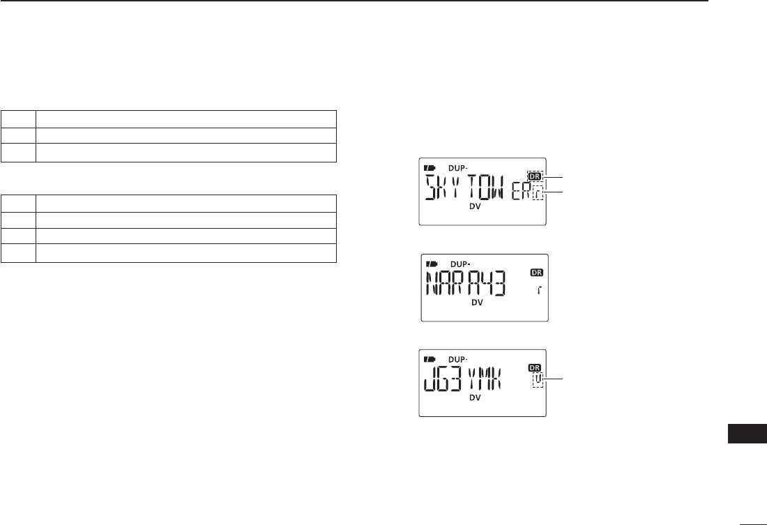
- When transceiver is selected DR mode:
[A] Selects access repeater selection.
[B] Selects your call sign and link repeater selection.
[Y] Repeater selection or station call sign selection “UP.”
[Z] Repeater selection or station call sign selection “DOWN.”
D DR mode operation using HM-75A
q Push [A] to enter the access repeater selection on DR
mode.
Appear
Repeater selection
indicator
w Push [Y] or [Z]to select the access repeater.
e Push [B] to enter the your call sign selection.
UR selection
indicator
r Push [Y] or [Z]to select the your call sign.
t Push [B] to enter the link repeater (RPT2) selection.
y Push [Y] or [Z]to select the link repeater.
u Push [PTT] to transmit; release to receive.
164
16 OPTIONS
q Turn the transceiver power OFF.
w Remove the rubber cap. from the [SP/MIC] jack.
e Connect the HM-189GPS to the [SP/MIC] jack.
r Turn the transceiver power ON, then push the top key of
the HM-189GPS to turn the GPS receiver power ON.
• Key illumination lights when GPS receiver is turned
ON. “G” indicator blinks on the transceiver’s display.
• Key illumination blinks when GPS receiver receives GPS
signals. Then “G” indicator stays ON
on the transceiver’s
display
.
t Position, elevation, time, direction, etc. can be displayed.
See Section 8 “GPS/GPS-A OPERATION” for details.
GPS indicator
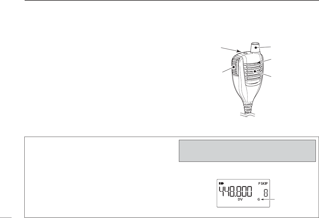
The optional HM-189GPS has a GPS receiver and allows
you to operate the IC-80AD’s GPS functions.
q
PTT SWITCH
Push and hold to transmit; release to receive.
w TOP KEY
Push to turn the GPS receiver’s power ON and OFF.
• Key illumination lights when GPS receiver is turned ON.
Key illumination lights OFF when it’s OFF.
• Key illumination blinks when GPS receiver receives
GPS signals.
Speaker
PTT switch
TOP key
Microphone
GPS antenna
q
w
N Optional HM-189GPS PP RCROPO
CAUTION!: Turn power OFF the transceiver before
connecting/disconnecting HM-189GPS to/from the
[SP/MIC] jack.
D GPS receiver power ON

1-1-32 Kamiminami, Hirano-ku, Osaka 547-0003, Japan
A-6700D-1EX
Printed in Japan
©2009 Icom Inc.
Printed on recycled paper with soy ink.