ICOM orporated 317600 VHF P25 Trunking Mobile Transceiver User Manual IC F9511HT Instruction Manual
ICOM Incorporated VHF P25 Trunking Mobile Transceiver IC F9511HT Instruction Manual
Contents
- 1. User Manual
- 2. User Manual 1
- 3. User Manual 2
User Manual

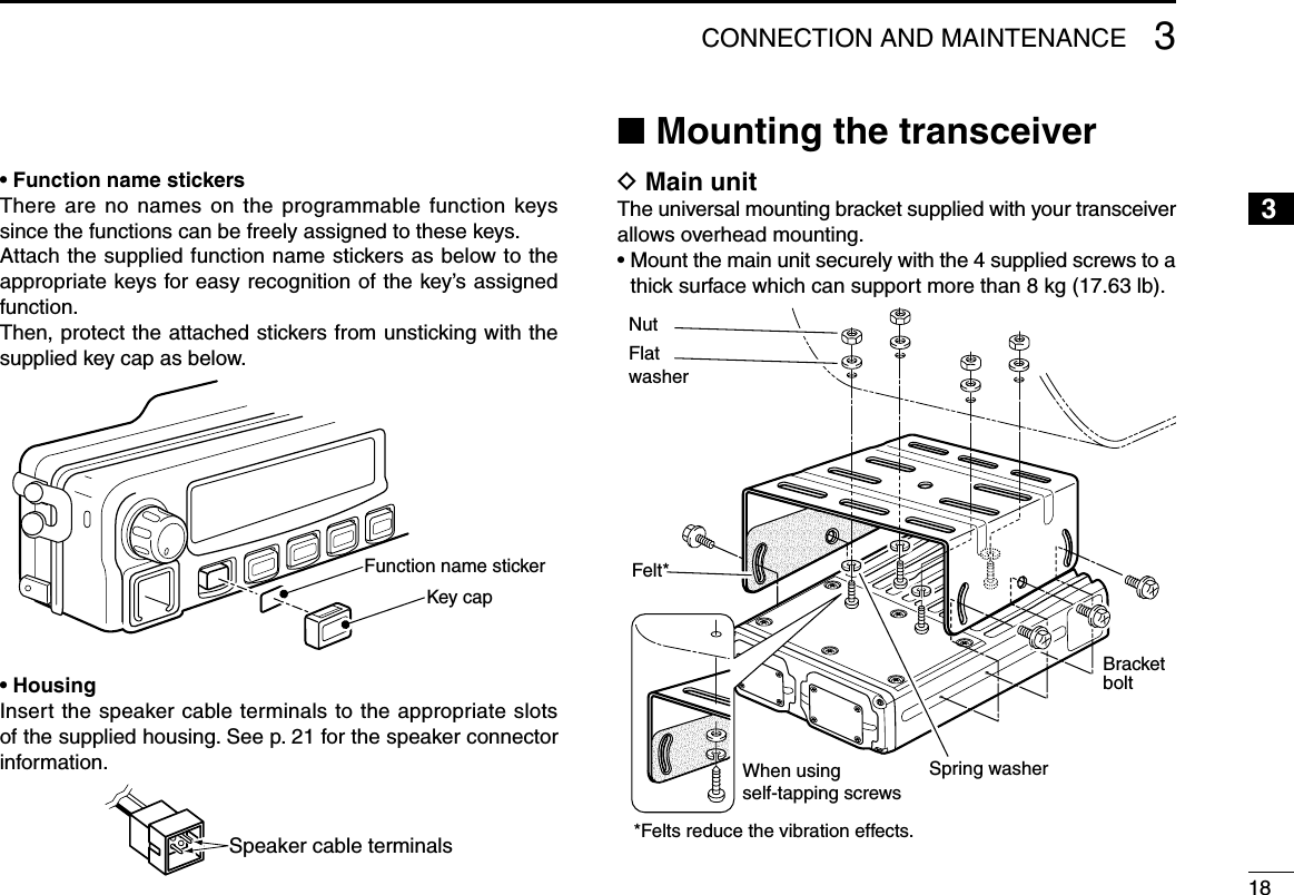
![21PANEL DESCRIPTION12345678910111213141516y POWER SWITCH [POWER] Push to turn the power ON and OFF. • The following functions are available at power ON as options: - Automatic scan start - Password prompt - Set modeu TRANSMIT INDICATOR Lights red while transmitting.i DEALER-PROGRAMMABLE KEYS Desired functions can be programmed independently by your dealer. (p. 4) In this instruction manual, these keys are from the left, called [P0]/[P1]/[P2]/[P3]/[P4].o MICROPHONE CONNECTOR Connect the supplied or optional microphone. • When you connect a microphone, be sure to fit the connector cover of the microphone into the connector to maintain the con-troller’s dust protection and splash resistance.Connector cover NEVER connect non-specified microphones. The pin assignments may be different and the transceiver may be damaged.D MICROPHONE The supplied microphone has a PTT switch and a hanger hook. • The following functions are available when the microphone is on or off hook (depending on the setting): - Automatic scan starts when it is on hook. - Scan is cancelled when it is off hook. - Scan is paused when it is off hook. - Automatic priority channel selection is available when it is off hook. - Sets to ‘Inaudible’ condition (mute condition) when it is on hook. - Sets to ‘Audible’ condition (unmute condition) when it is off hook.!0 SPEAKER JACK Connect a 4–8 ø external speaker. • Max. input power: 7 W • Attach the jack cover when no external speaker is connected.Jack cover](https://usermanual.wiki/ICOM-orporated/317600.User-Manual/User-Guide-1063777-Page-7.png)
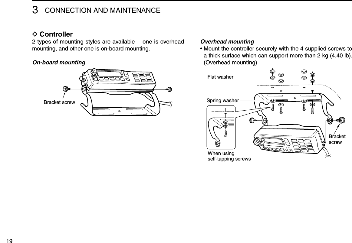
![31PANEL DESCRIPTIONn Function display— Controller0 1 c h - 0 1I c - F 9 5 1 1 H Tuq w e r t y i!0oq RECEIVED SIGNAL STRENGTH INDICATOR Indicates relative signal strength level.Weak Receive Signal level Strong w LOW POWER INDICATOR Appears when low output power is selected. • When high output power is selected, no indicator appears.e AUDIBLE INDICATOR Appears when the channel is in the ‘audible’ (unmute) con-dition.r COMPANDER INDICATOR Appears when the compander function* is activated. * Analog mode operation onlyt SCRAMBLER INDICATOR Appears when the voice scrambler or encryption function is activated.y BELL INDICATOR Appears/blinks when the specific page call* is received, depending on how the transceiver has been pre-pro-grammed. * P25 operation onlyu TELEPHONE INDICATOR Appears when a phone call* is received. * P25 operation onlyi SHORT MESSAGE INDICATOR Appears when an Status message or Short message is received.o ALPHANUMERIC DISPLAY Displays an operating channel number, channel name, Set mode contents, DTMF code, etc. !0 ACTIVATED KEY INDICATOR Appears above the key assigned as [Scan Add/Del (Tag)] key when that key has been activated.See the operating guide for details of Analog and P25 Trunking/Conventional system operations. Consult your Icom dealer or system operator for details concerning your transceiver’s programming.](https://usermanual.wiki/ICOM-orporated/317600.User-Manual/User-Guide-1063777-Page-8.png)
![41PANEL DESCRIPTION12345678910111213141516n Programmable function keysThe following functions can be assigned to [UP], [DOWN], [P0], [P1], [P2], [P3] and [P4] programmable function keys.Consult your Icom dealer or system operator for details con-cerning your transceivers programming.If the programmable function names are bracketed in the fol-lowing explanations, the specific key is used to activate the function depends on the programming.CH UP AND DOWN KEYS ➥ Push to select an operating channel.➥ Push to select a scan group after pushing and holding [Scan A Start/Stop]/[Scan B Start/Stop].ZONE KEYPush this key, then push [CH Up] or [CH Down] to select the desired zone.What is “zone”?—The desired channels are assigned into a zone according to the intended use for grouping. For example, ‘Staff A’ and ‘Staff B’ are assigned into a “Business” zone, and ‘John’ and ‘Cindy’ are assigned into a “Private” zone.SCAN A START/STOP KEY➥ Push to start and cancel scanning operation. • When Power ON Scan function is activated, push to pause the scanning operation. And the paused scan resumes after the specified time period has passed.➥ Push and hold this key for 1 sec. to indicate the scan list, then push [CH Up] or [CH Down] to select the desired list. (Available depending on the pre-setting.)SCAN B START/STOP KEY➥ Push to start and cancel scanning operation. The scan restarts after the specified time period has passed when the scan (started with this key) is cancelled by except for this key operation.➥ Push and hold this key for 1 sec. to indicate the scan list, then push [CH Up] or [CH Down] to select the desired list.SCAN ADD/DEL (TAG) KEYPush to add or delete the selected channel to/from the scan list.1. Push to indicate the scan list, then push [CH Up] or [CH Down] to select the desired list.2. Push to add or delete the channel to/from the selected scan list.3. Push and hold for 1 sec. to exit the scan list selection mode.](https://usermanual.wiki/ICOM-orporated/317600.User-Manual/User-Guide-1063777-Page-9.png)
![51PANEL DESCRIPTIONPRIO A/B KEYS➥ Push to select Priority A or Priority B channel.➥ Push and hold [Prio A (Rewrite)] or [Prio B (Rewrite)] for 1 sec. to rewrite the operating channel as the Priority A or Priority B channel.MR-CH 1/2/3/4 KEYSPush to select the memory channel 1 to 4 directly.MONI KEYMute and release the CTCSS (DTCS), NAC or Talkgroup ID squelch mute. Open any squelch/deactivate any mute while pushing this key.TALK AROUND KEY (Conventional operation only)Turn the talk around function ON and OFF.• The talk around function equalizes the transmit frequency to the receive frequency for transceiver-to-transceiver communication.PUBLIC ADDRESS KEYPush to activate the Public Address (PA) function for voice amplification. When the PA function is activated, the audio output can be controlled from the transceiver separately with [CH Up] or [CH Down].• This function is available when the external unit, such as a audio amplifier, speaker, etc. is additionally connected. (p. 16)• Push this key, then speak into the microphone while pushing and holding [PTT].NOTE: “PA/RX Speaker” setting should be turned OFF by your dealer with the CS-F9010/F9510 cloning software to activate the PA function. Ask your dealer for details.RX SPEAKER KEYPush to turn the RX speaker function ON or OFF.When the RX speaker function is turned ON, the received audio can be heard via the external speaker.• This function is available when the external speaker is additionally connected. (p. 16)• This function is useful when you are out of the vehicle.• The audio output level is linked to the transceiver’s volume control.DO NOT operate this key with this transceiver. Otherwise no audio may be emitted. LOCK KEYPush and hold to electronically lock all programmable keys except the following:[Moni], [Light], [Lock], [Emergency Single], [Emergency Repeat], [Surveillance] and [OPT 1/2/3].LIGHT KEYPush to turn the transceiver’s backlight ON for about 5 sec. when the backlight function is turned OFF in user set mode. (p. 12)HIGH/LOW KEYPush to select the transmit output power temporarily or per-manently, depending on the pre-setting.• Ask your dealer for the output power level for each selection.](https://usermanual.wiki/ICOM-orporated/317600.User-Manual/User-Guide-1063777-Page-10.png)
![61PANEL DESCRIPTION12345678910111213141516SURVEILLANCE KEYPush to turn the surveillance function ON or OFF.When this function is turned ON, the beep is not emitted and the LCD backlight does not light when a signal is received or a key is pushed, etc.HOOK SCAN KEYWhen the on hook scan function is activated, push this key to stop scanning temporarily. Push this key again to re-start scanning.USER SET MODE KEY➥ Push and hold to enter user set mode. • During in the user set mode, push this key to select an item that is enabled by your dealer, and change the value or condition by pushing [CH Up] or [CH Down].➥ Push and hold this key again to exit user set mode.User set mode is also available via the ‘Power ON function.’ Refer to p. 12 also.OPT 1/2/3 KEYSPush to control the output signal level from the optional unit connector.CLOCK KEY➥ Push to indicate the current time on the LCD. (p. 9) • While the current time is indicated, push and hold this key for 1 sec. to enter the time data edit mode. (p. 9)➥ Push and hold for 1 sec. to enter the clock set mode. (pgs. 10, 11) • During in the clock set mode, push this key to select an item, and change the value or condition by pushing [CH Up] or [CH Down].HOME KEYPush to return to normal operation.](https://usermanual.wiki/ICOM-orporated/317600.User-Manual/User-Guide-1063777-Page-11.png)
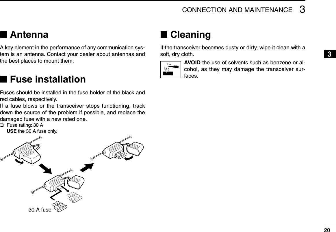
![72BASIC OPERATIONn Turning power ONWhen you use the transceiver for the first time, or after the transceiver has been left unused for a long time, make sure to check the date and time indication after turning the power ON. If the time and date are not correct, reset them. (p. 9)q Push [ ] to turn the power ON.w If the transceiver is programmed for a start up password, input the digit codes as directed by your dealer. • 10-keypad can be used for password input. • The keys as below can be used for password input: The transceiver detects numbers in the same block as identical. Therefore “01234” and “56789” are the same.KEY P0 P1 P2 P3 P4NUMBER 0516273849P0 P4P3P2P1*In this instruction manual, these keys are from the left, called [P0]/[P1]/[P2]/[P3]/[P4].e When the “PASSWORD” indication does not clear after in-putting 6 digits, the input code number may be incorrect. Turn the power off and start over in this case.n Channel selectionSeveral types of channel selections are available. Methods may differ according to your system set up.NON-ZONE TYPE:To select the desired operating channel:• Push [CH Up] or [CH Down].• Push one of [MR-CH 1] to [MR-CH 4].ZONE TYPE:To select the desired zone:• Push [Zone], then push [CH Up] or [CH Down].AUTOMATIC SCAN TYPE:Channel setting is not necessary for this type. When turn-ing power ON, the transceiver automatically starts scanning. Scanning stops when receiving a call.](https://usermanual.wiki/ICOM-orporated/317600.User-Manual/User-Guide-1063777-Page-12.png)
![82BASIC OPERATION12345678910111213141516n Receiving and transmittingReceiving:q Push [ ] to turn the power ON.w Push [CH Up] or [CH Down] to select a channel in se-quence.e While receiving a call, adjust the audio output level to a comfortable listening level.Transmitting:Wait for the channel to become clear to avoid interference.q Take the microphone off hook. • The ‘audible’ condition is selected and BUSY indicator lights green. • A priority channel may be selected automatically.w Wait for the channel to become clear. • The channel is busy when BUSY indicator lights green.e While pushing and holding [PTT], speak into the micro-phone at your normal voice level.r Release [PTT] to receive.IMPORTANT: To maximize the readability of your signal;1. Pause briefly after pushing [PTT].2. Hold the microphone 5 to 10 cm (2 to 4 inches) from your mouth, then speak into the microphone at a normal voice level.D Transmitting notes• Transmit inhibit functionThe transceiver has several inhibit functions which restrict transmission under the following conditions:- The channel is in mute condition (‘Inaudible’ condition; “ ” does not appear.)- The channel is busy.- Un-matched (or matched) CTCSS is received. (Depending on the pre-setting)- Un-matched (or matched) NAC is received.* (Depending on the pre-setting)- The selected channel is a ‘receive only’ channel.*Digital mode operation only.• Time-out timerAfter continuous transmission for the pre-programmed time period, the time-out timer is activated, causing the transceiver to stop transmitting.• Penalty timerOnce the time-out timer is activated, transmission is further inhibited for a period determined by the penalty timer.](https://usermanual.wiki/ICOM-orporated/317600.User-Manual/User-Guide-1063777-Page-13.png)
![92BASIC OPERATIONn Clock functionThe transceiver indicates the current time and date when [Clock] is pushed. And you can change the indication format and time/date settings.When you use the transceiver for the first time, or after the transceiver has been left unused for a long time, make sure to check the date and time indication after turning the power ON. If the time and date are not correct, reset them. D Time and date indicationq Push [Clock] to indicate the current time and date on the LCD. • When the indication format is set to 12-hour, “AM” or “PM” is indicated. • The LCD indication returns to the stand-by mode after 30 sec. has passed with no operation.1 2 H R 12 : 0 0 P MY M D 0 8- 0 4 - 0 1The time indication format (12-hour/24-hour) TimeDateDate indication format (Y: Year, M: Month, D: Day) w Push [Clock] again to return to the stand-by mode.D Time and date settingsq Push [Clock] to indicate the current time and date on the LCD.1 2 H R 12 : 0 0 P MY M D 0 8- 0 4 - 0 1w Push and hold [Clock] for 1 sec. to enter the time and date setting mode. • The time indication format, “24HR” or “12HR” blinks.1 2 H R 12 : 0 0 P MY M D 0 8- 0 4 - 0 1e Push [Clock] to select the desired item to be changed.r Push [CH Up] or [CH Down] to set the selected item.1 2 H R 03 : 0 0 P MY M D 0 8- 0 4 - 0 1](https://usermanual.wiki/ICOM-orporated/317600.User-Manual/User-Guide-1063777-Page-14.png)
![102BASIC OPERATION12345678910111213141516t Push [Clock] to set. • The next item blinks.1 2 H R 03 : 0 0 P MY M D 0 8- 0 4 - 0 1y Repeat steps e to t to set items.u After setting, push and hold [Clock] for 1 sec. to program. • Return to the time and date setting mode.i Push [Clock] to return to the stand-by mode.n Wake up functionThe wake up function allows the transceiver to be automati-cally turned ON according to the wake up time setting.q Push and hold [Clock] for 1 sec. to enter the clock set mode. • “WAKE UP” is indicated.W A K E UPO F Fw Push [CH Up] or [CH Down] to turn the wake up function ON.e Push [Clock] to set, and select “WAKE UP TIME.”W A K E UP T I M E07:25AMr Push [CH Up] or [CH Down] to enter the wake up time edit mode. • The ‘hour’ digit blinks.W A K E UP T I M E07:25AM☞ Continues to the next page](https://usermanual.wiki/ICOM-orporated/317600.User-Manual/User-Guide-1063777-Page-15.png)
![112BASIC OPERATIONt Push [CH Up] or [CH Down] to input the ‘hour’ data for wake up time. After inputting, push [Clock] to set. • The ‘minutes’ digit blinks.W A K E UP T I M E09:25AMy Push [CH Up] or [CH Down] to input the ‘minutes’ data for wake up time. After inputting, push [Clock] to set.W A K E UP T I M E09:30AMu Push and hold [Clock] for 1 sec. to exit the clock set mode. • Return to the stand-by mode.n Sleep functionThe sleep function allows the transceiver to be automatically turned OFF according to the sleep time setting.q Push and hold [Clock] for 1 sec. to enter the clock set mode. • “WAKE UP” is indicated.w Push [Clock] several times to select “SLEEP.”SLEEPO Ne Push [CH Up] or [CH Down] to turn the sleep function ON.r Push [Clock] to set, and select “SLEEP TIME.”S L E E P T I M E05:35PMt Push [CH Up] or [CH Down] to enter the sleep time edit mode. • The ‘hour’ digit blinks.S L E E P T I M E05:35PM](https://usermanual.wiki/ICOM-orporated/317600.User-Manual/User-Guide-1063777-Page-16.png)
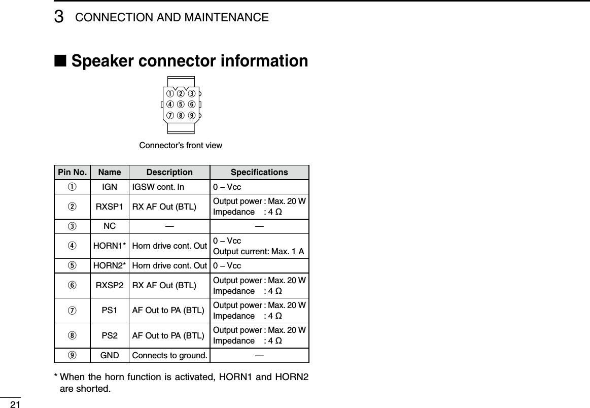
![122BASIC OPERATION12345678910111213141516y Push [CH Up] or [CH Down] to input the ‘hour’ data for sleep time. After inputting, push [Clock] to set. • The ‘minutes’ digit blinks.S L E E P T I M E08:35PMu Push [CH Up] or [CH Down] to input the ‘minutes’ data for sleep time. After inputting, push [Clock] to set.S L E E P T I M E08:00PMi Push and hold [Clock] for 1 sec. to exit the clock set mode. • Return to the stand-by mode.n User set modeThe user set mode is accessed at power ON and allows you to set seldom-changed settings. You can “customize” the transceiver operation to suit your preferences and operating style.Entering the user set mode:q While pushing and holding [P1] and [P2], push [ ] to turn the power ON. • Turn power OFF in advance. • You should hold [P1] and [P2] until “SET MODE” appears on the display.[P1] [P2] [ ]w Push and hold [P0] to enter user set mode.[P0]☞ Continues to the next page](https://usermanual.wiki/ICOM-orporated/317600.User-Manual/User-Guide-1063777-Page-17.png)
![e Push [P0] several times to select the appropriate item. Then, push [Up] or [Down] to set the desired level/condi-tion. • Available set mode functions are Backlight, LCD Contrast, Beep, Beep Level, Ringer Level, SQL Level, AF Min. Level, Mic Gain, Horn, Battery Voltage, Signal Moni and System In-formation.[P0] [Up]/[Down]r Push [ ] again to exit set mode.[ ]User set mode is also available via a programmable key. Please refer to p. 6 [User Set Mode Key] section.132BASIC OPERATION](https://usermanual.wiki/ICOM-orporated/317600.User-Manual/User-Guide-1063777-Page-18.png)