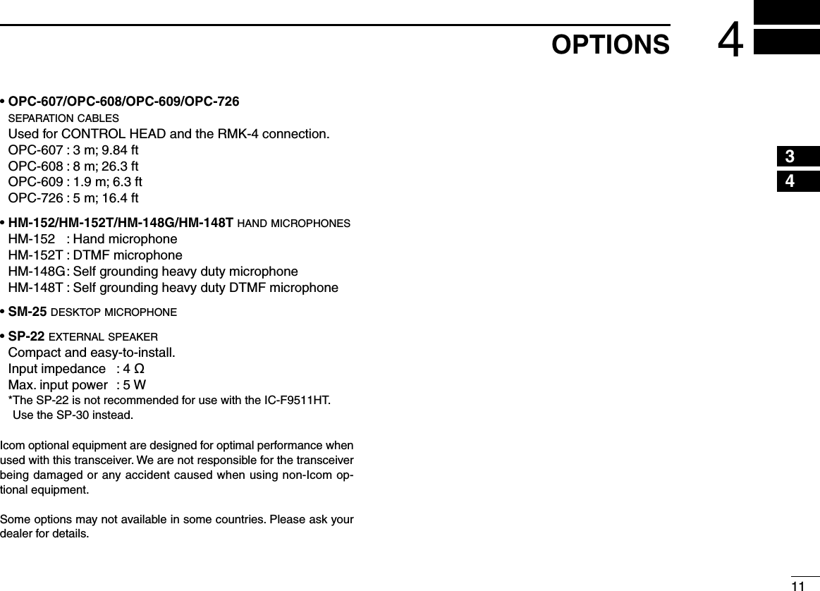
ICOM orporated 317600 VHF P25 Trunking Mobile Transceiver User Manual RMK 4 Instruction Manual
ICOM Incorporated VHF P25 Trunking Mobile Transceiver RMK 4 Instruction Manual
UserManual.wiki
>
ICOM orporated
>
317600 User Manual
>
User Manual 2
Contents
1.
User Manual
2.
User Manual 1
3.
User Manual 2
User Manual 2
Navigation menu
Upload a User Manual
Namespaces
Wiki Guide
HTML
PDF
Info
Views
User Manual
Discussion / Help
Navigation
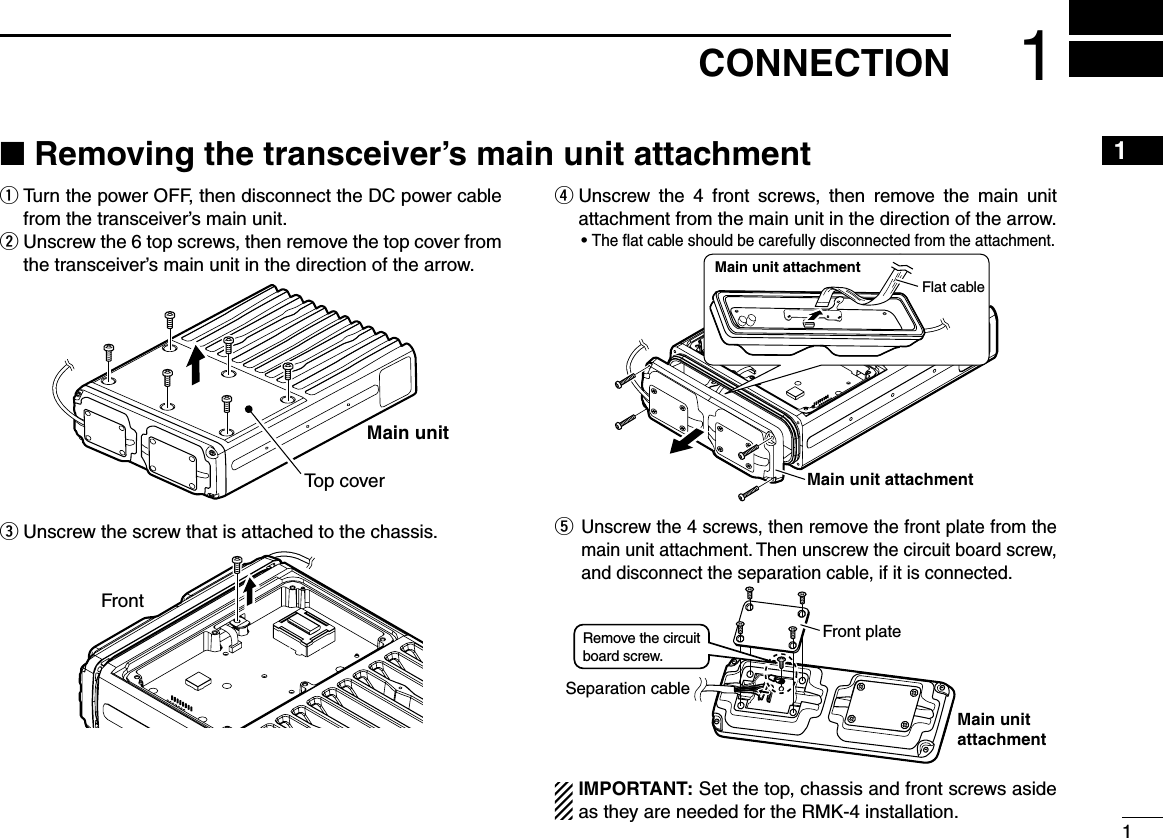
![Either the optional OPC-607 (3 m; 9.84 ft), OPC-608 (8 m; 26.3 ft), OPC-609 (1.9 m; 6.3 ft) or OPC-726 (5 m; 16.4 ft) separation cable is required for CONTROL HEADs and the RMK-4 connections.INFORMATION: CONTROL HEAD connected to the [CONTROL HEAD 1] of the RMK-4, is recognized as the main CONTROL HEAD.D CONTROL HEADYou can connect the separation cable to both CONTROL HEADs in the same way, as shown below.q Unscrew the 4 screws, then remove the rear plate from CONTROL HEAD.CONTROL HEADRear plateUnscrew the circuit board screw.w Connect the separation cable to CONTROL HEAD. • The cable can be inserted into either the left or right grooves as needed.SeparationcableCablegrooveCONTROL HEADReinstall the circuit board screw removed in step q as shown at left to con-nect the cable terminal.Rear platee After the cable is connected, reinstall the rear plate and the 4 screws, then connect the opposite side of the sepa-ration cable to the RMK-4.r Repeat steps q to e to attach the other CONTROL HEAD.If the separation cable is already connected to the original CONTROL HEAD, the above connection should be per-formed to the second CONTROL HEAD only.21CONNECTION■ Connecting CONTROL HEAD and RMK-4](https://usermanual.wiki/ICOM-orporated/317600.User-Manual-2/User-Guide-1126757-Page-6.png)
![The REMOTE BOX SET MODE is accessed at power ON and allows you to set seldom-changed settings. You can “customize” CONTROL HEADs for dual-head operation to suit your preferences and operating style.P0 P4P3P2P1*In this instruction manual, these keys are from the left, designated [P0]/[P1]/[P2]/[P3]/[P4].D Set mode operationq First, be sure power is OFF. Then, while pushing and holding [P0], [P1] and [P2], push [ ] to turn the power ON. • Hold [P0], [P1] and [P2] until “SET MODE FOR REMOTE BOX” appears on the display.w Push [P0] to enter the REMOTE BOX SET MODE.e Then push [P0] additional times to select the appropriate item. Then, push [Up] or [Down] to set the desired level and conditions.r Push and hold [ ] to exit the REMOTE BOX SET MODE.The USER SET MODE is also available. The common functions that can be used with both dual-head and sin-gle-head operations are set in the USER SET MODE. Please refer to the instruction manual of the transceiver for details.■ Set mode itemsThe following functions (other than “RX Speaker Tune”) can be programmed into CONTROL HEADs 1 and 2, individu-ally.D AF MinimumSet the AF Minimum function to ON or OFF. (default: ON)ON : The minimum audio output level is set for CONTROL HEADs. • Set the minimum audio output level in “AF Minimum Level” as shown below.OFF : The minimum audio output level is not set for CON-TROL HEADs.D AF Minimum LevelSet the minimum audio output level between 0 and 255. (default: 0)This setting is effective only when “AF Minimum” is ON as shown above.D Beep LevelSet the output level of the confirmation beeps between 1 and 5. (default: 3)This setting is effective for dual-head operation functions only.The beep level for other functions that can be used with both dual-head and single-head operations, are set in the USER SET MODE.62REMOTE BOX SET MODE](https://usermanual.wiki/ICOM-orporated/317600.User-Manual-2/User-Guide-1126757-Page-10.png)
![D Panel Lock functionSet the Panel Lock function to ON or OFF. (default: ON)The Panel Lock function locks all keys and the dial other than [ ] and [P4 (PANEL LOCK)].ON : The [PANEL LOCK] function is assigned to [P4], and you can toggle the Panel Lock function ON and OFF with pushing and holding [P4 (PANEL LOCK)] for 1 sec.OFF : [P4] retains the originally programmed function and the Panel Lock function is OFF.NOTE: When this function is set to ON, the key function [Null] must be assigned to [P4] by the CS-F9010/F9510 cloning software on both CONTROL HEADs for match-ing the CONTROL HEAD’s performance. Ask your dealer for details.D TX AF Monitoring functionSet the TX AF Monitoring function to ON or OFF. (default: ON)This function allows the operator of CONTROL HEAD to monitor the other side’s communication.When one CONTROL HEAD operator is communicating, the audio can be heard from the SP-22 external speaker on the other CONTROL HEAD side.The optional SP-22 external speaker is required.D Hanger functionSet the Hanger function to ON or OFF. (default: ON)The microphone “on-hook” function (Hook-on scan) and “off-hook” functions (Move to Priority A CH and Monitor) are acti-vated according to this setting.ON : The microphone “on-hook” or “off-hook” functions are activated when CONTROL HEAD’s microphone is put on (on hook) or taken off (off-hook) it's hanger hook.OFF : The microphone “on-hook” function is activated regard-less of the CONTROL HEAD’s microphone “on-hook” and “off-hook”.NOTE: If “ON” is set in both CONTROL HEADs and one of the two microphones is taken from its hanger hook, the microphone “off-hook” functions are activated for both CONTROL HEADs.72REMOTE BOX SET MODE12345678910111213141516](https://usermanual.wiki/ICOM-orporated/317600.User-Manual-2/User-Guide-1126757-Page-11.png)
![82REMOTE BOX SET MODED RX Speaker Tuning functionSet the RX Speaker Tuning function to ON or OFF for CON-TROL HEAD 1 (main). (default: OFF)This function allows the operator of CONTROL HEAD 1 to adjust the output level of the external speaker that is con-nected to the transceiver’s main unit.ON : The audio output level of the external speaker is adjust-able with the AF volume control knob on CONTROL HEAD 1. The minimum audio output level must be set to more than 1 on the transceiver’s main unit in order to avoid muting the audio output.OFF : The audio output level of the external speaker is not adjustable by CONTROL HEADs.D Intercom functionSet the Intercom function to ON or OFF. (default: ON)The Intercom function allows CONTROL HEAD operators to communicate each other via their microphones.The optional microphone and the SP-22 external speaker are required.ON : The [INTERCOM] function is assigned to [P3], and you can enter and exit the Intercom mode by pushing [P3 (INTERCOM)].OFF : [P3] retains the originally programmed function and the Intercom function is OFF.NOTE:• When one CONTROL HEAD enters the Intercom mode, the other CONTROL HEAD also enters even if this func-tion is set to OFF.• When this function is set to ON, the key function [Null] must be assigned to [P3] by the CS-F9010/F9510 clon-ing software on both CONTROL HEADs for matching the CONTROL HEAD’s performance. Ask your dealer for details.](https://usermanual.wiki/ICOM-orporated/317600.User-Manual-2/User-Guide-1126757-Page-12.png)
![93DUAL-HEAD OPERATION12345678910111213141516■ Intercom function[P3] is used for the Intercom function ON/OFF switch when the Intercom function is set to ON in the REMOTE BOX SET MODE. (No other function can be assigned.)The Intercom function allows the operators of CONTROL HEAD 1 and 2 to communicate each other via their micro-phones.The optional microphone and the SP-22 external speaker are required.NOTE:• Transmitting is impossible during intercom operation.• During intercom operation, when [PTT] is pushed and held on the caller’s side, any received radio signal is muted on the listener side’s CONTROL HEAD external speaker. However, the received radio signal can be heard on the caller side’s CONTROL HEAD external speaker and the main unit’s external speaker.• When the message signal is received, it is not displayed on the LCD of CONTROL HEADs during intercom opera-tion. After exiting the intercom mode, it will be displayed on the LCD.• During intercom operation, CONTROL HEADs 1 and 2 return to the normal operation mode, if no [PTT] opera-tion is performed for 30 sec.q Push [P3 (INTERCOM)] to enter the intercom mode. • The other CONTROL HEAD is also set to the Intercom mode automatically even if this function is set to OFF. • “INTERCOM” appears on both CONTROL HEADs.w Push and hold [PTT] and speak at a normal voice level into the microphone. • “IN USE” blinks on the listener side. • To adjust the audio output level, rotate [VOL].e After releasing [PTT] you can hear the response through the speaker.r To return to normal operation, push [P3 (INTERCOM)].](https://usermanual.wiki/ICOM-orporated/317600.User-Manual-2/User-Guide-1126757-Page-13.png)