ICOM orporated 317600 VHF P25 Trunking Mobile Transceiver User Manual RMK 4 Instruction Manual
ICOM Incorporated VHF P25 Trunking Mobile Transceiver RMK 4 Instruction Manual
Contents
- 1. User Manual
- 2. User Manual 1
- 3. User Manual 2
User Manual 2

INSTRUCTION MANUAL
RMK-4
SEPARATION KIT
i
FOREWORD
Thank you for purchasing the RMK-4 separation kit.
The RMK-4 allows you to connect the additional CONTROL
HEAD to the IC-F9511HT to enable dual-head operation.
Depending on the length of separation you need, use either
the optional OPC-607, OPC-608, OPC-609 or OPC-726 sep-
aration cable with the RMK-4.
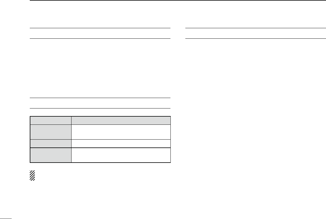
EXPLICIT DEFINITIONS
WORD DEFINITION
RWARNING Personal injury, fire hazard or electric
shock may occur.
CAUTION Equipment damage may occur.
NOTE
If disregarded, inconvenience only. No risk
of personal injury, fire or electric shock.
Please refer to the instruction manual of the transceiver
for details of the basic operation.
PRECAUTIONS
RWARNING! NEVER place the transceiver’s main unit
(with the RMK-4) and CONTROL HEADs where normal operation of
the vehicle may be hindered or where they could cause bodily injury.
CAUTION! To avoid damage to the transceiver, turn the
power OFF and disconnect the DC power cable from the trans-
ceiver’s main unit before disassemble the transceiver.
DO NOT use or place the transceiver’s main unit (with the
RMK-4) and CONTROL HEADs in areas with temperatures
below –30°C (–22°F) or above +60°C (+140°F).
DO NOT use chemical agents such as benzine or alcohol
when cleaning, as they can damage the RMK-4 and CONTROL
HEAD’s surfaces.
USE the specified microphone only. Other microphones have
different pin assignments and may damage CONTROL HEAD or
the transceiver’s main unit.
KEEP the transceiver’s main unit (with the RMK-4) and CON-
TROL HEADs away from heavy rain, and never immerse them
in the water.
The transceiver’s main unit (with the RMK-4) and CONTROL
HEADs meet IP54 requirements for dust-protection and splash
resistance when the optional microphone*, the front/rear plate(s)
and the speaker jack cover of CONTROL HEAD are attached.
However, if these items are dropped, dust-protection and splash
resistance cannot be guaranteed because of possible damage to
the cases or the waterproof seals.
* The microphone is not dust-protection and splash resistant.
Icom, Icom Inc. and the Icom logo are registered trademarks of Icom Incor-
porated (Japan) in Japan, the United States, the United Kingdom, Germany,
France, Spain, Russia and/or other countries.
All other products or brands are registered trademarks or trademarks of their
respective holders.
ii
1
2
3
4
5
6
7
8
9
10
11
12
13
14
15
16
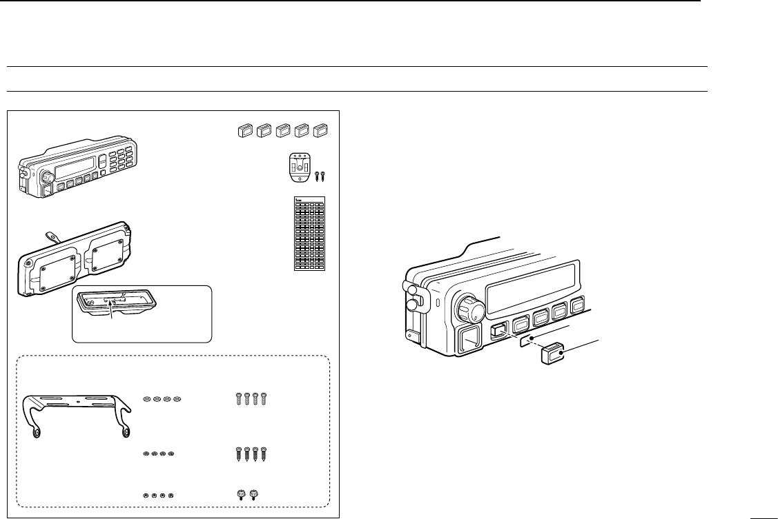
KEY-STICKER
Second CONTROL HEAD
RMK-4 (Main unit attachment)
Microphone hanger
and screw set
Mounting bracket
for CONTROL HEAD Flat washers
(M5)
Spring
washers (M5)
Mounting screws
(M5×12)
Self-tapping screws
(M5×16)
Bracket screws
Nuts (M5)
Key caps
Function name
stickers
• Used for labelling
the programmable
function keys. See
at right for details.
The serial number seal is put
here, and labeled “RMK-4.”
• Function name stickers
There are no labels on the programmable function keys since
the functions can be freely assigned to these keys.
Attach the supplied function name stickers to the appropriate
keys for easy recognition of the key’s assigned function as
shown below.
Then, protect the attached stickers from coming off with the
supplied key cap, as shown below.
Function name sticker
Key cap
ACCESSORIES

TABLE OF CONTENTS
iii
FOREWORD ......................................................................... i
EXPLICIT DEFINITIONS ....................................................... i
PRECAUTIONS ..................................................................... i
ACCESSORIES .................................................................... ii
TABLE OF CONTENTS ....................................................... iii
1 CONNECTION .............................................................1−5
■ Removing the transceiver’s main unit attachment ........1
■ Connecting CONTROL HEAD and RMK-4 ..................2
■ Attaching the RMK-4 ....................................................4
■ Mounting ......................................................................4
2 REMOTE BOX SET MODE .........................................6−8
■ Set mode items ............................................................6
3 DUAL-HEAD OPERATION ........................................9−10
■ Intercom function ..........................................................9
■ TX AF Monitoring function ..........................................10
■ NOTES .......................................................................10
4 OPTIONS .......................................................................11
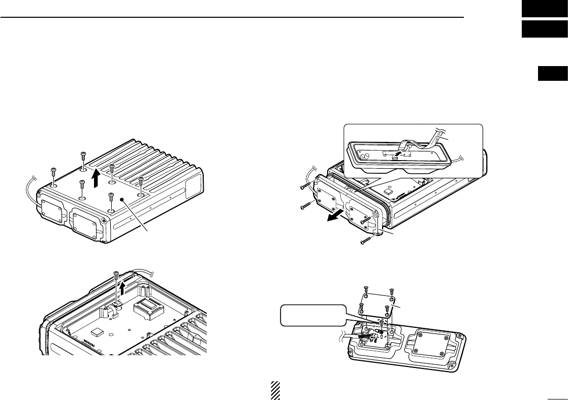
q Turn the power OFF, then disconnect the DC power cable
from the transceiver’s main unit.
w Unscrew the 6 top screws, then remove the top cover from
the transceiver’s main unit in the direction of the arrow.
Top cover
Main unit
e Unscrew the screw that is attached to the chassis.
Front
r
Unscrew the 4 front screws, then remove the main unit
attachment from the main unit in the direction of the arrow.
•
The flat cable should be carefully disconnected from the attachment.
Main unit attachment
Main unit attachment
Flat cable
t
Unscrew the 4 screws, then remove the front plate from the
main unit attachment. Then unscrew the circuit board screw,
and disconnect the separation cable, if it is connected.
Main unit
attachment
Separation cable
Front plate
Remove the circuit
board screw.
IMPORTANT: Set the top, chassis and front screws aside
as they are needed for the RMK-4 installation.
1
1
CONNECTION
1
2
3
4
5
6
7
8
9
10
11
12
13
14
15
16
■ Removing the transceiver’s main unit attachment
Either the optional OPC-607 (3 m; 9.84 ft), OPC-608 (8 m;
26.3 ft), OPC-609 (1.9 m; 6.3 ft) or OPC-726 (5 m; 16.4 ft)
separation cable is required for CONTROL HEADs and the
RMK-4 connections.
INFORMATION: CONTROL HEAD connected to the
[CONTROL HEAD 1] of the RMK-4, is recognized as the
main CONTROL HEAD.
D CONTROL HEAD
You can connect the separation cable to both CONTROL
HEADs in the same way, as shown below.
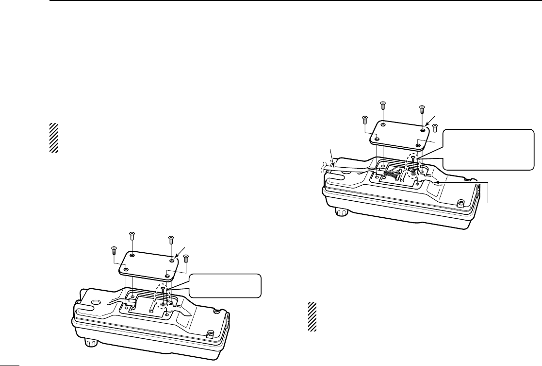
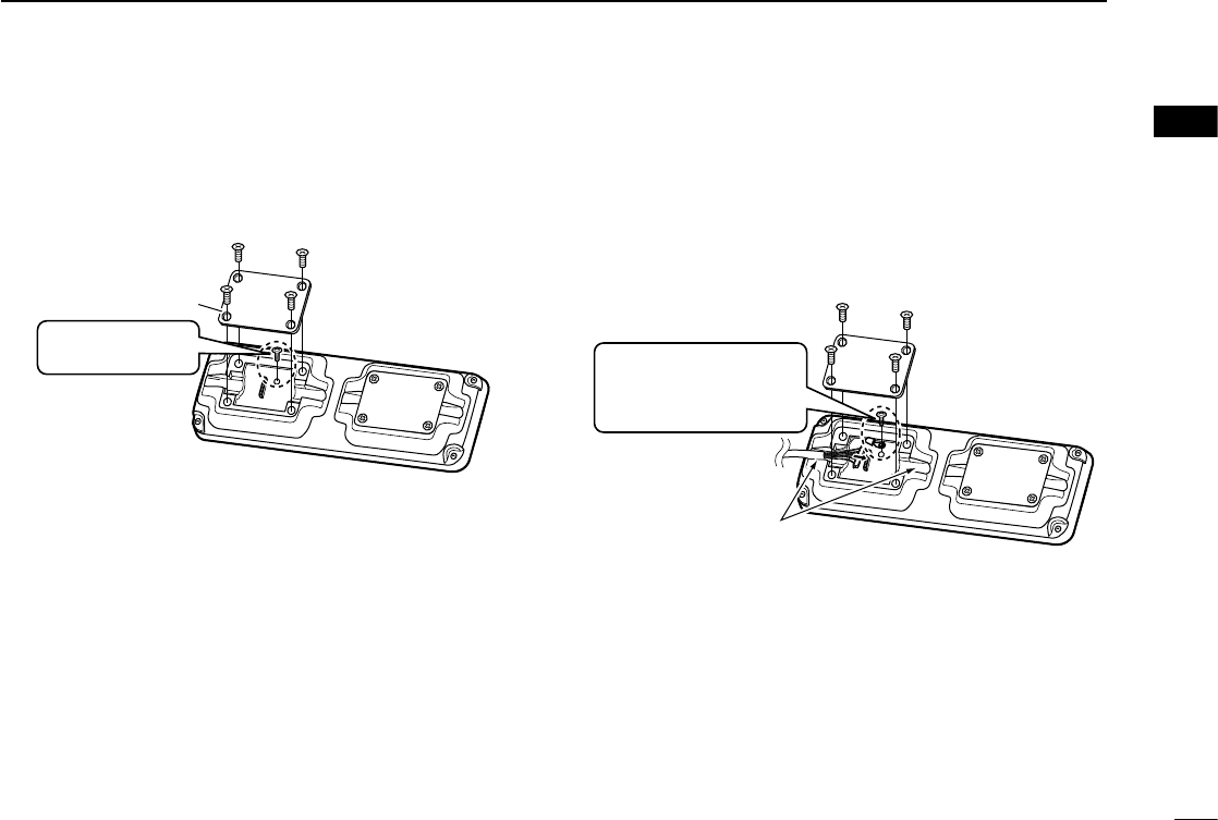
q Unscrew the 4 screws, then remove the rear plate from
CONTROL HEAD.
CONTROL HEAD
Rear plate
Unscrew the circuit
board screw.
w Connect the separation cable to CONTROL HEAD.
• The cable can be inserted into either the left or right grooves as
needed.
Separation
cable
Cable
groove
CONTROL HEAD
Reinstall the circuit board
screw removed in step q
as shown at left to con-
nect the cable terminal.
Rear plate
e After the cable is connected, reinstall the rear plate and
the 4 screws, then connect the opposite side of the sepa-
ration cable to the RMK-4.
r Repeat steps q to e to attach the other CONTROL
HEAD.
If the separation cable is already connected to the original
CONTROL HEAD, the above connection should be per-
formed to the second CONTROL HEAD only.
2
1CONNECTION
■ Connecting CONTROL HEAD and RMK-4
3
1
CONNECTION
1
2
3
4
5
6
7
8
9
10
11
12
13
14
15
16
D RMK-4
q Unscrew the 4 screws, then remove the front plate from
the
RMK-4
.
RMK-4
Front plate
Unscrew the circuit
board screw.
w Connect the opposite side of the separation cable that is
connected to CONTROL HEAD to the RMK-4. After the
cable is connected, reinstall the front plate and the 4 screws.
• The cable can be inserted into either the left or right grooves as
needed.
Separation
cable
Cable grooves
Reinstall the circuit board
screw removed in step q
as shown above to con-
nect the cable terminal.
e Repeat steps q and w for the other
side connection.
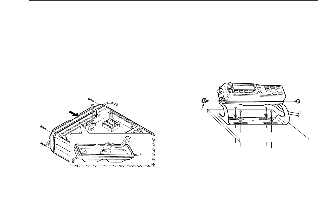
■ Attaching the RMK-4
q
Carefully connect the flat cable of the transceiver’s main
unit to the RMK-4 as shown below (q).
Then, attach the RMK-4 to the transceiver’s main unit
using 4 front screws that were removed from the main unit
in step r in p. 1. (w)
• Ensure the flat cable and the RMK-4 are connected/attached
correctly, and not upside down.
w
Replace the screw that was removed from the main unit in
step e in p. 1 to the chassis. (e)
Main unit
RMK-4
RMK-4
w
e
Flat cable
q
e
Replace the top cover and 6 top screws removed in step
w in p. 1, then reconnect the DC power cable.
■ Mounting
2 types of mounting styles are available— one is on-board
mounting, and the other one is overhead mounting.
D On-board mounting
Mount the controller securely with the 4 supplied screws to a
solid surface.
Bracket
screw
4
1CONNECTION
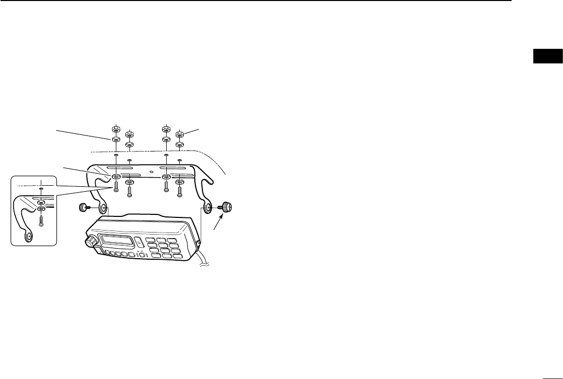
D Overhead mounting
Mount the controller securely with the 4 supplied screws to
a solid surface which can support more than 2 kg (4.40 lb).
(Overhead mounting)
When using
self-tapping screws
Flat washer
Spring washer
Bracket
screw
Nut
5
1
CONNECTION
1
2
3
4
5
6
7
8
9
10
11
12
13
14
15
16
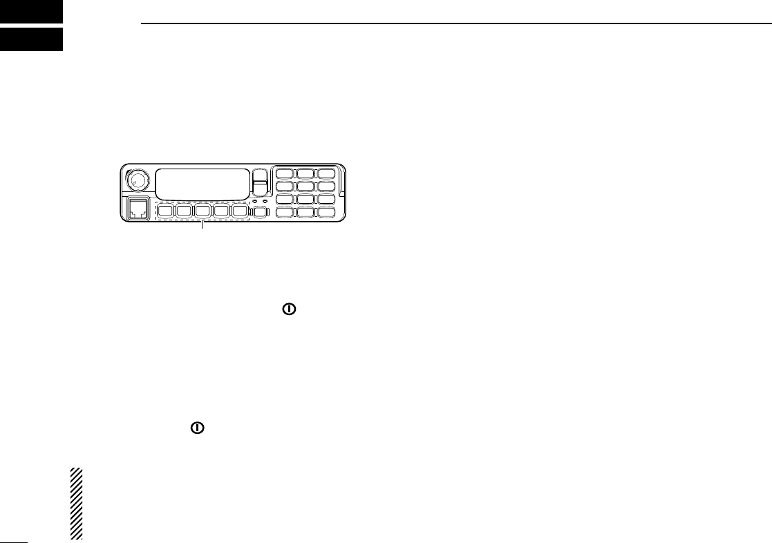
The REMOTE BOX SET MODE is accessed at power ON
and allows you to set seldom-changed settings. You can
“customize” CONTROL HEADs for dual-head operation to
suit your preferences and operating style.
P0 P4P3P2P1
*In this instruction manual, these keys are from
the left, designated [P0]/[P1]/[P2]/[P3]/[P4].
D Set mode operation
q First, be sure power is OFF. Then, while pushing and
holding [P0], [P1] and [P2], push [ ] to turn the power
ON.
• Hold [P0], [P1] and [P2] until “SET MODE FOR REMOTE BOX”
appears on the display.
w Push [P0] to enter the REMOTE BOX SET MODE.
e Then push [P0] additional times to select the appropriate
item. Then, push [Up] or [Down] to set the desired level
and conditions.
r Push and hold [ ] to exit the REMOTE BOX SET
MODE.
The USER SET MODE is also available. The common
functions that can be used with both dual-head and sin-
gle-head operations are set in the USER SET MODE.
Please refer to the instruction manual of the transceiver
for details.
■ Set mode items
The following functions (other than “RX Speaker Tune”) can
be programmed into CONTROL HEADs 1 and 2, individu-
ally.
D AF Minimum
Set the AF Minimum function to ON or OFF. (default: ON)
ON : The minimum audio output level is set for CONTROL
HEADs.
• Set the minimum audio output level in “AF Minimum Level”
as shown below.
OFF : The minimum audio output level is not set for CON-
TROL HEADs.
D AF Minimum Level
Set the minimum audio output level between 0 and 255.
(default: 0)
This setting is effective only when “AF Minimum” is ON as
shown above.
D Beep Level
Set the output level of the confirmation beeps between 1 and
5. (default: 3)
This setting is effective for dual-head operation functions only.
The beep level for other functions that can be used with both
dual-head and single-head operations, are set in the USER
SET MODE.
6
2REMOTE BOX SET MODE

D Panel Lock function
Set the Panel Lock function to ON or OFF. (default: ON)
The Panel Lock function locks all keys and the dial other than
[ ] and [P4 (PANEL LOCK)].
ON : The [PANEL LOCK] function is assigned to [P4], and
you can toggle the Panel Lock function ON and OFF
with pushing and holding [P4 (PANEL LOCK)] for
1 sec.
OFF : [P4] retains the originally programmed function and the
Panel Lock function is OFF.
NOTE: When this function is set to ON, the key function
[Null] must be assigned to [P4] by the CS-F9010/F9510
cloning software on both CONTROL HEADs for match-
ing the CONTROL HEAD’s performance. Ask your dealer
for details.
D TX AF Monitoring function
Set the TX AF Monitoring function to ON or OFF. (default: ON)
This function allows the operator of CONTROL HEAD to
monitor the other side’s communication.
When one CONTROL HEAD operator is communicating, the
audio can be heard from the SP-22 external speaker on the
other CONTROL HEAD side.
The optional SP-22 external speaker is required.
D Hanger function
Set the Hanger function to ON or OFF. (default: ON)
The microphone “on-hook” function (Hook-on scan) and “off-
hook” functions (Move to Priority A CH and Monitor) are acti-
vated according to this setting.
ON : The microphone “on-hook” or “off-hook” functions are
activated when CONTROL HEAD’s microphone is put
on (on hook) or taken off (off-hook) it's hanger hook.
OFF : The microphone “on-hook” function is activated regard-
less of the CONTROL HEAD’s microphone “on-hook”
and “off-hook”.
NOTE: If “ON” is set in both CONTROL HEADs and one of
the two microphones is taken from its hanger hook, the
microphone “off-hook” functions are activated for both
CONTROL HEADs.
7
2
REMOTE BOX SET MODE
1
2
3
4
5
6
7
8
9
10
11
12
13
14
15
16

8
2REMOTE BOX SET MODE
D RX Speaker Tuning function
Set the RX Speaker Tuning function to ON or OFF for CON-
TROL HEAD 1 (main). (default: OFF)
This function allows the operator of CONTROL HEAD 1 to
adjust the output level of the external speaker that is con-
nected to the transceiver’s main unit.
ON : The audio output level of the external speaker is adjust-
able with the AF volume control knob on CONTROL
HEAD 1.
The minimum audio output level must be set to more
than 1 on the transceiver’s main unit in order to avoid
muting the audio output.
OFF : The audio output level of the external speaker is not
adjustable by CONTROL HEADs.
D Intercom function
Set the Intercom function to ON or OFF. (default: ON)
The Intercom function allows CONTROL HEAD operators to
communicate each other via their microphones.
The optional microphone and the SP-22 external speaker
are required.
ON : The [INTERCOM] function is assigned to [P3], and
you can enter and exit the Intercom mode by pushing
[P3 (INTERCOM)].
OFF : [P3] retains the originally programmed function and the
Intercom function is OFF.
NOTE:
• When one CONTROL HEAD enters the Intercom mode,
the other CONTROL HEAD also enters even if this func-
tion is set to OFF.
• When this function is set to ON, the key function [Null]
must be assigned to [P3] by the CS-F9010/F9510 clon-
ing software on both CONTROL HEADs for matching
the CONTROL HEAD’s performance. Ask your dealer for
details.

9
3
DUAL-HEAD OPERATION
1
2
3
4
5
6
7
8
9
10
11
12
13
14
15
16
■ Intercom function
[P3] is used for the Intercom function ON/OFF switch when
the Intercom function is set to ON in the REMOTE BOX SET
MODE. (No other function can be assigned.)
The Intercom function allows the operators of CONTROL
HEAD 1 and 2 to communicate each other via their micro-
phones.
The optional microphone and the SP-22 external speaker
are required.
NOTE:
• Transmitting is impossible during intercom operation.
• During intercom operation, when [PTT] is pushed and
held on the caller’s side, any received radio signal is
muted on the listener side’s CONTROL HEAD external
speaker. However, the received radio signal can be heard
on the caller side’s CONTROL HEAD external speaker
and the main unit’s external speaker.
• When the message signal is received, it is not displayed
on the LCD of CONTROL HEADs during intercom opera-
tion. After exiting the intercom mode, it will be displayed
on the LCD.
• During intercom operation, CONTROL HEADs 1 and 2
return to the normal operation mode, if no [PTT] opera-
tion is performed for 30 sec.
q Push [P3 (INTERCOM)] to enter the intercom mode.
•
The other CONTROL HEAD is also set to the Intercom mode
automatically
even if this function is set to OFF
.
• “INTERCOM” appears on both CONTROL HEADs.
w Push and hold [PTT] and speak at a normal voice level
into the microphone.
• “IN USE” blinks on the listener side.
• To adjust the audio output level, rotate [VOL].
e After releasing [PTT] you can hear the response through
the speaker.
r To return to normal operation, push [P3 (INTERCOM)].

■ TX AF Monitoring function
When the TX AF Monitoring function is set to ON in the RE-
MOTE BOX SET MODE, and one CONTROL HEAD operator
is communicating, the audio can be heard from the SP-22
external speaker on the other CONTROL HEAD side.
The optional SP-22 external speaker is required.
NOTE: When one CONTROL HEAD operator is communi-
cating, “IN USE” blinks on the other CONTROL HEAD’s
display and the TX indicators lights red.
I N U SE
■ NOTES
• Transmission can be performed on either CONTROL HEADs
1 or 2 at the same time.
• The Power ON Password function will not work properly
when attaching the RMK-4.
• The RMK-4 is not designed for the single-head operation.
For single-head operation, use the original attachment and
cable combination— no RMK-4 is necessary.
But when the one of CONTROL HEADs is accidently bro-
ken, the RMK-4 may go into the unintended single-head op-
eration mode. In that case, the Intercom function MUST be
turned OFF. Otherwise, any problem may occur.
10
3DUAL-HEAD OPERATION

11
4
OPTIONS
1
2
3
4
5
6
7
8
9
10
11
12
13
14
15
16
• OPC-607/OPC-608/OPC-609/OPC-726
separation cables
Used for CONTROL HEAD and the RMK-4 connection.
OPC-607 : 3 m; 9.84 ft
OPC-608 : 8 m; 26.3 ft
OPC-609 : 1.9 m; 6.3 ft
OPC-726 : 5 m; 16.4 ft
• HM-152/HM-152T/HM-148G/HM-148T hand microphones
HM-152 : Hand microphone
HM-152T : DTMF microphone
HM-148G : Self grounding heavy duty microphone
HM-148T : Self grounding heavy duty DTMF microphone
• SM-25 desktop microphone
• SP-22 external speaker
Compact and easy-to-install.
Input impedance : 4 ø
Max. input power : 5 W
* The SP-22 is not recommended for use with the IC-F9511HT.
Use the SP-30 instead.
Icom optional equipment are designed for optimal performance when
used with this transceiver. We are not responsible for the transceiver
being damaged or any accident caused when using non-Icom op-
tional equipment.
Some options may not available in some countries. Please ask your
dealer for details.

1-1-32 Kamiminami, Hirano-ku, Osaka 547-0003, Japan
A-6757H-1US
Printed in Japan
© 2009 Icom Inc.
Printed on recycled paper with soy ink.