ICOM orporated 318200 HF/50 MHz Tranceiver User Manual IC 7600 Instruction Manual
ICOM Incorporated HF/50 MHz Tranceiver IC 7600 Instruction Manual
UserManual.wiki
>
ICOM orporated
>
318200 User Manual
User Manual
Navigation menu
Upload a User Manual
Namespaces
Wiki Guide
HTML
PDF
Info
Views
User Manual
Discussion / Help
Navigation
![PRECAUTIONSR WARNING HIGH RF VOLTAGE! NEVER attach an antenna or internal antenna connector during transmission. This may result in an electrical shock or burn.R WARNING! NEVER operate the transceiver with a headset or other audio accessories at high volume levels. Hearing experts advise against continu-ous high volume operation. If you experience a ringing in your ears, reduce the volume or discontinue use.R WARNING! NEVER operate or touch the transceiver with wet hands. This may result in an electric shock or damage to the transceiver.R WARNING! NEVER apply AC power to the [DC13.8V] socket on the transceiver rear panel. This could cause a fire or damage the transceiver.R WARNING! NEVER apply more than 16 V DC to the [DC13.8V] socket on the transceiver rear panel, or use reverse polarity. This could cause a fire or damage the transceiver.R WARNING! NEVER let metal, wire or other objects protrude into the transceiver or into connectors on the rear panel. This may result in an electric shock.R WARNING! Immediately turn OFF the trans-ceiver power and remove the power cable if it emits an abnormal odor, sound or smoke. Contact your Icom dealer or distributor for advice.#!54)/. .%6%2 put the transceiver in any unstable place (such as on a slanted surface or vibrated place). This may cause injury and/or damage to the transceiver.#!54)/. NEVER change the internal settings of the transceiver. This may reduce transceiver perfor-mance and/or damage to the transceiver.In particular, incorrect settings for transmitter circuits, such as output power, idling current, etc., might damage the expensive final devices.The transceiver warranty does not cover any prob-lems caused by unauthorized internal adjustment.#!54)/. NEVER block any cooling vents on the top, rear, sides or bottom of the transceiver.#!54)/. NEVER expose the transceiver to rain, snow or any liquids.#!54)/. NEVER install the transceiver in a place without adequate ventilation. Heat dissipation may be reduced, and the transceiver may be damaged.DO NOT use harsh solvents such as benzine or alcohol when cleaning, as they will damage the trans-ceiver surfaces.DO NOT push the PTT switch when you don’t actu-ally desire to transmit.DO NOT use or place the transceiver in areas with temperatures below ±0°C (+32°F) or above +50°C (+122°F).DO NOT place the transceiver in excessively dusty environments or in direct sunlight.DO NOT place the transceiver against walls or putting anything on top of the transceiver. This may overheat the transceiver.Always place unit in a secure place to avoid inadver-tent use by children."% #!2%&5, If you use a linear amplifier, set the transceiver’s RF output power to less than the linear amplifier’s maximum input level, otherwise, the linear amplifier will be damaged."% #!2%&5, The rear panel will become hot when operating the transceiver continuously for long periods of time.USE only the specified microphone. Other manufac-turers’ microphones have different pin assignments, and connection to the IC-7410 may damage the transceiver or microphone.During maritime mobile operation, keep the trans-ceiver and microphone as far away as possible from the magnetic navigation compass to prevent errone-ous indications.Turn OFF the transceiver’s power and/or disconnect the DC power cable when you will not use the trans-ceiver for long period of time.ii123456789101112131415161718192021](https://usermanual.wiki/ICOM-orporated/318200/User-Guide-1398232-Page-3.png)
![iiiTABLE OF CONTENTSFOREWORD .............................................................. iIMPORTANT ............................................................... iEXPLICIT DEFINITIONS ............................................ iSUPPLIED ACCESSORIES....................................... iFCC INFORMATION .................................................. iPRECAUTIONS ......................................................... ii4!",%/&#/.4%.43 ........................................... iii1 PANEL DESCRIPTION................................... 1–14N Front panel ........................................................ 1N Rear panel ......................................................... 8 D ACC socket information .............................. 10N LCD display ..................................................... 11N Function display .............................................. 13 D M1 (Menu 1) ............................................... 13 D Function keys on M1 (Menu 1) ................... 13 D M2 (Menu 2) ............................................... 14 D Function keys on M2 (Menu 2) ................... 142 INSTALLATION AND CONNECTIONS ........ 15–22N Selecting a location ......................................... 15N Grounding ....................................................... 15N Antenna connection ........................................ 15N Required connections ..................................... 16 D Front panel .................................................. 16 D Rear panel .................................................. 16N Advanced connections .................................... 17 D Front panel .................................................. 17 D Rear panel .................................................. 17N External keypad connections .......................... 18N External antenna tuner connection ................. 18 D Connecting the AH-4 .................................. 18N Power supply connections ............................... 19N Connecting to a DC power supply ................... 19 D Connecting to the PS-126 DC POWER SUPPLY ...................................................... 19 D Connecting to a non-Icom DC POWER SUPPLY ...................................................... 19N Linear amplifier connections ........................... 20 D Connecting the IC-PW1/PW1EURO ........... 20 D Connecting a non-Icom linear amplifier ...... 21N Microphone connector information .................. 22N Microphones .................................................... 22 D HM-36 ........................................................ 22 D SM-50 (Option) ........................................... 223 "!3)#/0%2!4)/. ..................................... 23–34N Before first applying power .............................. 23N Turning ON (CPU resetting) ............................ 23N VFO description ............................................... 24 D Selecting the VFO A/B ............................... 24 D VFO equalization ........................................ 24N Selecting VFO/Memory mode ......................... 24N Selecting a frequency band ............................. 25 D Using the band stacking registers. .............. 25N Frequency setting ............................................ 26 D Tuning with [DIAL] ...................................... 26 D Direct frequency entry with the keypad ....... 26 D Quick Tuning function .................................. 27 D Selecting 1 Hz step ..................................... 27 D 1⁄4 Tuning Step function .............................. 27 D Auto Tuning Step function .......................... 28 D About the 5 MHz frequency band operation (USA version only) ...................................... 28 D Band edge warning beep ............................ 29 D Programming the user band edge .............. 30N Operating mode selection ............................... 31N Volume setting ................................................. 31N Squelch and receive (RF) sensitivity ............... 32N Voice synthesizer operation ............................ 33N Meter Display selection ................................... 33N Basic transmit operation .................................. 34 D Transmitting ................................................. 34 D Microphone gain adjustment ....................... 34](https://usermanual.wiki/ICOM-orporated/318200/User-Guide-1398232-Page-4.png)
![vTABLE OF CONTENTS7 MEMORY OPERATION ................................ 69–74N General description ......................................... 69 D Memory channel contents ........................... 69N Memory channel selection .............................. 69 D Selection in the VFO mode ......................... 69 D Selection in the Memory mode ................... 69N Memory channel programming ....................... 70 D Programming in the VFO mode .................. 70 D Programming in the Memory mode ............. 70N Memory clearing ............................................. 71N Memory contents copying ............................... 72 D Copying in the VFO mode ........................... 72 D Copying in the Memory mode ..................... 72NMemory name programming ........................... 73NMemo Pad function ......................................... 74 D Writing the displayed data into a memo pad .. 74 D Calling up a memo pad ............................... 748 SCANS ......................................................... 75–81N Scan types ...................................................... 75N Preparation ...................................................... 76N Voice Squelch Control function ....................... 76N Scan Set mode ................................................ 77N Programmed scan/Fine programmed scan (VFO mode) .................................................... 78 D About the Fine programmed scan ............... 78N Memory scan (Memory mode) ........................ 79 D Memory scan .............................................. 79 D Select Memory scan ................................... 80 D Setting/Cancelling Select Memory channels .80N ∂F scan and Fine ∂F scan ............................. 81 D About the Fine ∂F scan .............................. 819 ANTENNA TUNER OPERATION ................. 82–84N Antenna connection and selection .................. 82N Antenna tuner operation .................................. 83 D Tuner operation ........................................... 83 D Manual tuning ............................................. 83N Optional external tuner operation .................... 8410 SET MODE ................................................... 85–91N Set mode description ...................................... 85 D The Set mode settings ................................ 85N Tone Control Set mode description ................. 90 D The Tone control Set mode settings ........... 9011 DATA COMMUNICATION ............................. 92–93N Connections .................................................... 92 D When connecting to [ACC].......................... 92 D When connecting to [MIC] .......................... 92N Packet (AFSK) operation ................................. 93 D Frequency display during AFSK operation . 9312 OPTION INSTALLATION ............................. 94–95N Opening the transceiver’s case ....................... 94N FL-430/FL-431 1ST IF FILTER installation .......... 9513 MAINTENANCE ......................................... 96–100N Troubleshooting ............................................... 96 D Transceiver power ....................................... 96 D Transmit and receive ................................... 96 D Scanning ..................................................... 97 D Display ........................................................ 97N Dial tuning tension adjustment ........................ 97N Frequency calibration (approximate) ............... 98N About protection displays ................................ 98N Fuse replacement ........................................... 99 D DC power cable fuse replacement .............. 99 D Circuitry fuse replacement .......................... 99N Resetting the CPU ........................................ 100 D Partial reset ............................................... 100 D All reset ..................................................... 100](https://usermanual.wiki/ICOM-orporated/318200/User-Guide-1398232-Page-6.png)
![q POWER SWITCH [POWER] (p. 23) ± Push to turn ON the transceiver power. s&IRSTCONlRMTHE$#POWERSOURCEISTURNED/. ± Hold down for 1 second to turn OFF the power.w TRANSMIT SWITCH [TRANSMIT] (p. 34) Push to select transmit or receive. s7HILETRANSMITTINGTHE48INDICATOR@1) lights red. s7HILERECEIVINGORWHENTHESQUELCHOPENSTHE28INDI-cator (i) lights green.e ANTENNA TUNER SWITCH [TUNER] (pp. 83, 84) ± Push to turn the internal antenna tuner ON or OFF (bypass). s7HENTHETUNERIS/.h ” appears.s4HEINTERNALANTENNATUNERSETTINGSCANBEMEMO-rized in each frequency band. ± Hold down for 1 second to manually start the an-tenna tuner.s)FTHETUNERCANNOTTUNETHEANTENNAWITHINSEC-onds, the tuning circuit is automatically bypassed.r !.4%..!s-%4%237)4#(;!.4s-%4%2= ANTENNA SWITCH Operation ± Push to select either the ANT1 or ANT2 connec-tor. (p. 82) METER SWITCH Operation± Hold down for 1 second to display either the COMP or SWR meter in addition to the ALC meter. (p. 33)t HEADPHONE JACK [PHONES] (p. 17) Plug in standard stereo headphones. Impedance: 8 to 16 ø. s/UTPUTPOWERM7WITHANø load.s7HENHEADPHONESARECONNECTEDTHEINTERNALSPEAKERand any external speaker, are disabled.y ELECTRONIC KEYER JACK [ELEC-KEY] Plug in a bug or paddle type key to use the internal electronic keyer for CW operation. (p. 16)s3ELECTTHE%,%#+%9"5'+%9OR3TRAIGHTKEYKEYERtype in the “Keyer Type” item of the Keyer Set mode.s!STRAIGHTKEYJACKISLOCATEDONTHEREARPANEL3EE[KEY] on page 16.s9OUCANREVERSE THE KEYERPADDLEPOLARITY DOT ANDdash) in the “Paddle Polarity” item of the Keyer Set mode. (p. 42)s&OURKEYERMEMORYCHANNELSAREAVAILABLEFORYOURCON-venience. (p. 40)(dot)(com)(dash)u MICROPHONE CONNECTOR [MIC] Plug in the supplied or optional microphone.s3EEPAGEFORAPPROPRIATEMICROPHONESANDMICRO-phone connector information.i RX INDICATOR Lights green while receiving or when the squelch opens.o AF CONTROL [AF] (inner control; p. 31) Rotate to adjust audio output level to the speaker or headphones.N Front panel11PANEL DESCRIPTIONIncreasesDecreasesti !4!3 !5 !6yeru!0wq!2!1o](https://usermanual.wiki/ICOM-orporated/318200/User-Guide-1398232-Page-8.png)
![!0 RF GAIN CONTROL/SQUELCH CONTROL [RF/SQL] (outer control; p. 32) Rotate to adjust the RF gain and squelch threshold level. The squelch removes noise output to the speaker when no signal is received (closed condition). s4HESQUELCHIS PARTICULARLY EFFECTIVEIN&- BUT ALSOworks in other modes. s4HETOOCLOCKPOSITIONISRECOMMENDEDfor the most effective use of the [RF/SQL] control. s;2&31,=OPERATESASONLYAN2&GAINCONTROLIN33"CW and RTTY (Squelch is fixed open), or a squelch control in AM and FM (RF gain is fixed at maximum sensitivity), when the “RF/SQL Control” item is set to “Auto” in the Set mode. (p. 86)s7HENUSEDASAN2&GAINSQUELCHCONTROLMaximum RF gainS-meter squelchNoise squelch (FM mode)Squelch is open.RF gain adjustablerangeRecommended levels7HENUSEDASAN2&GAINCONTROL (Squelch is fixed open; SSB, CW and RTTY only)Minimum RF gainAdjustablerangeMaximum RF gainWhile rotating the RF gain control, a faint noise may be heard. This comes from the DSP unit and does not indicate an equipment malfunction.s7HENUSEDASASQUELCHCONTROL (RF gain is fixed at maximum.)Squelch is open.S-meter squelchS-meter squelchthresholdNoise squelch threshold (FM mode)Shallow DeepNoise squelch (FM mode)!1 MIC GAIN CONTROL [MIC] (inner control; p. 34) Rotate to adjust the microphone gain.s4HETRANSMITAUDIOTONEINTHE33"!-AND&-MODEScan be independently adjusted in the Tone Control Set mode. (pp. 90, 91) How to set the microphone gain.While speaking at normal voice level, adjust the mi-crophone gain so that in the SSB or AM modes, the ALC meter swings within the ALC zone.Recommended level for Icom microphonesIncreaseDecreases !2 RF POWER CONTROL [RF PWR] (outer control; p. 34) Rotate to continuously vary the RF output power between 2 W (minimum) and 100 W (maximum). (AM: between 2 W and 27 W).!3 ELECTRONIC CW KEYER SPEED CONTROL [KEY SPEED] (p. 37) -ODE#7 Rotate to adjust the keying speed of the internal electronic CW keyer to between 6 wpm (minimum) and 48 wpm (maximum).FastSlow!4"2%!+).$%,!9#/.42/,;"+).$%,!9= (p. 63) -ODE#7 Rotate to adjust the transmit-to-receive switching delay time for the Semi Break-in function.Long delay for slow speed keyingShort delay for high speed keying!5 COMPRESSOR CONTROL [COMP] (p. 64) -ODE33" Rotate to adjust the compression level.IncreasesDecreases!6 MONITOR GAIN CONTROL [MONI GAIN] (p. 65) Rotate adjust the monitor level for the clearest audio output.IncreasesDecreases21PANEL DESCRIPTION123456789101112131415161718192021](https://usermanual.wiki/ICOM-orporated/318200/User-Guide-1398232-Page-9.png)
![!7./)3%",!.+%237)4#(;."= (p. 60) ± Push to turn the Noise Blanker ON or OFF. The Noise Blanker reduces pulse-type noise such as that generated by vehicle ignition systems. The Noise Blanker cannot be used in the FM mode, and is not effective for non-pulse-type noise. sh."vAPPEARSWHENTHE.OISE"LANKERIS/.± Hold down for 1 second to display the “NB” screen. Push to return to the previous screen display.!8./)3%",!.+%2,%6%,#/.42/,;."= (outer control; p. 60) Rotate to adjust the noise blanker threshold level when the Noise Blanker is ON. Set for maximum readability. s4OUSETHISCONTROLlRSTPUSH;."=!7). IncreasesDecreases!9 NOISE REDUCTION LEVEL CONTROL [NR] (inner control; p. 61) Rotate to adjust the DSP noise reduction level when the Noise Reduction is ON. Set for maximum readability. s4OUSETHISCONTROLlRSTPUSH;.2=@0).IncreasesDecreases@0 NOISE REDUCTION SWITCH [NR] (p. 61)Push to turn DSP Noise Reduction ON or OFF. sh.2vAPPEARSWHEN.OISE2EDUCTIONIS/.@1 TX INDICATOR Lights red while transmitting.@2 FUNCTION SWITCHES [F1]–[F5] (pp. 13, 14) Push to select the function which is indicated on the LCD display above each switch. s4HEFUNCTIONSVARYDEPENDINGONTHESELECTEDMENUand the operating mode.@3 MENU SWITCH [MENU] (pp. 13, 14) ± Push to change the set of functions assigned to switches ([F-1] to [F-5]). s4OGGLESBETWEENTHEFUNCTIONMENUS--ENUand M2 (Menu 2).± Hold down for 1 second to enter the Set mode. Push to return to the previous screen display.@4 MODE SWITCHES Push to select your desired operating mode. (p. 31)s4HEBUILTINSPEECHSYNTHESIZERANNOUNCESTHESELECTEDmode when the “SPEECH [MODE] SW” item is set to “ON” in the Set mode. (p. 87) ;33"= ± Push to alternately select the USB or LSB modes. sh53"vORh,3"vAPPEARS ± In the SSB mode, hold down for 1 second to se-lect the SSB data mode (USB-D, LSB-D).shD” appears in addition to “USB” or “LSB.” ± In the SSB data mode, push to return to the nor-mal SSB mode. [CW] Push to alternately select the CW and CW-R (CW reverse) modes. sh#7vORh#72vAPPEARSN Front panel (continued)31PANEL DESCRIPTION@1 @5 @6 @7 @8 @9 #1#0 #2@0 !9 !8 !7@4@2 @3](https://usermanual.wiki/ICOM-orporated/318200/User-Guide-1398232-Page-10.png)
![[RTTY] Push to alternately select the RTTY and RTTY-R (RTTY reverse) modes. sh2449vORh24492vAPPEARS [AM/FM] ± Push to alternately select the AM or FM modes. sh!-vORh&-vAPPEARS ± Hold down for 1 second to select the AM or FM data mode (AM-D/FM-D).shD” appears in addition to “AM” or “FM.” ± In the data mode, push to return to the normal AM or FM mode.@502%!-0s!44%.5!4/237)4#(;0!-0s!44= PREAMP SWITCH Operation (p. 55) Push to select one of two receive RF preamplifiers, or to bypass them. sh0!-0 ” is a wide dynamic range preamplifier. It is most effective for the 1.8 to 21 MHz bands.sh0!-0 ” is a high-gain preamplifier. It is most effec-tive for the 24 to 50 MHz bands.s.OINDICATORAPPEARSWHENTHEPREAMPLIlERSARENOTSE-lected. What is the preamplifier?The preamplifier amplifies signals in the front end to improve the S/N ratio and sensitivity. Select “P. AMP ” or “P. AMP ” when receiving weak sig-nals. ATTENUATOR SWITCH Operation (p. 55)± Hold down for 1 second to turn ON the attenua-tor. sh!44vAPPEARSWHENTHEATTENUATORIS/.± Push to turn OFF the attenuator. sh!44vDISAPPEARS What is the attenuator?The attenuator prevents a desired signal from being distorted when very strong signals are near it, or when very strong electromagnetic fields, such as from a broadcasting station, are near your location.@66/8"+).37)4#(;6/8"+).= VOX SWITCH Operation (p. 62) -ODE33"!-&-± Push to turn the VOX function ON or OFF.± Hold down for 1 second to display the “VOX” screen. Push to return to the previous screen display. What is the VOX function?The VOX function (voice operated transmission) automatically starts transmission when you speak into the microphone; then automatically returns to receive when you stop speaking. "+).37)4#( Operation (p. 63) -ODE#7 Push to toggle the Break-in function between semi break-in and full break-in, or to turn OFF the func-tion. What is the Break-in function?The Break-in function automatically switches be-tween transmit and receive with your CW keying. Using the Full Break-in function (QSK), you can hear the receive frequency in-between keying.@7 COMPRESSOR SWITCH [COMP] (p. 64) -ODE33" Push to turn the Speech Compressor function ON or OFF. sh#/-0vAPPEARSWHENTHISFUNCTIONIS/.@8 MONITOR SWITCH [MONITOR] (p. 65) Push to turn the Monitor function ON or OFF to lis-ten to your own transmitted audio. sh-/.)vAPPEARSWHENTHISFUNCTIONIS/.s)NTHE#7MODETHE#7SIDETONECANBEHEARDRE-gardless of the [MONITOR] switch setting.@9 SPEECH SWITCH [SPEECH] (p. 33) ± Push to audibly announce the S-meter level and the displayed frequency. ± Hold down for 1 second to audibly announce the S-meter level, the displayed frequency, and the operating mode. s4HE3,EVELANNOUNCEMENTCANBETURNED/&&INTHE“SPEECH S-Level” item of the Set mode. (p. 87) s7HEN2)4ANDOR∂TX are ON, the RIT/∂TX offset is not included in the frequency announcement.#0 FILTER SWITCH [FILTER] (p. 57) ± Push to select one of three IF filter settings ( / / ). s4HESELECTEDlLTERPASSBANDWIDTHANDSHIFTINGVALUEare displayed for 2 seconds on the LCD display. ± Hold down for 1 second to display the “FIL” screen (Filter) to set the filter passband width. Hold down for 1 second again to return to the previous screen display.#1 TUNING DIAL [DIAL] (p. 26) Rotate to change the operating frequency, select the Set mode settings, etc.#2 LOCK SWITCH [LOCK] (p. 61) Hold down for 1 second to turn the Dial Lock func-tion ON or OFF. s4HISFUNCTIONELECTRONICALLYLOCKS;$)!,= sh ” appears when this function is ON.41PANEL DESCRIPTION123456789101112131415161718192021](https://usermanual.wiki/ICOM-orporated/318200/User-Guide-1398232-Page-11.png)
![#3 TRANSMIT FREQUENCY CHECK SWITCH [XFC] ± During split frequency or repeater operation, hold down to listen to the transmit frequency. (pp. 52, 56)s7HILEHOLDINGDOWN THIS SWITCHTHETRANSMIT FRE-quency can be changed with [DIAL], keypad or memo pad.s7HENTHE3PLIT,OCKFUNCTIONISTURNED/.PUSH[XFC] to cancel the Dial Lock function. (p. 67) ± When the RIT function is turned ON, hold down to listen to the displayed frequency (RIT is temporarily cancelled). (p. 53) ± When the ∂TX function is turned ON, hold down to listen to the transmit frequency (including ∂TX frequency offset). (p. 65)#4 UP/DOWN SWITCHES [Y]/[Z] ± Push to change the operating channel. (p. 69) ± Hold down to continuously change the operating channel. #56&/%15!,):%37)4#(;!"= (p. 24)Hold down for 1 second to equalize frequencies of VFO A and B.#66&/3%,%#437)4#(;!"= (p. 24)Push to select either VFO A or VFO B to display.sh6&/!vORh6&/"vISDISPLAYEDDEPENDINGONTHESE-lection.#7 SPLIT SWITCH [SPLIT] ± Push to turn the Split function ON or OFF. (p. 66) sh30,)4vAPPEARSWHENTHE3PLITFUNCTIONIS/. ± Hold down for 1 second to activate the Quick Split function. (p. 67)s4HETRANSMITFREQUENCYSHIFTSFROMTHERECEIVEFRE-quency according to the “FM SPLIT Offset HF/50” setting in the Set mode. (p. 86)s4HE1UICK3PLITFUNCTIONCANBETURNED/&&INTHE“Quick SPLIT” item of the Set mode. (p. 86)#8"!.$+%93+%90!$ "!.$+%93/PERATION (p. 25) ± Push to select the operating band. s;'%.s=SELECTSTHEGENERALCOVERAGEBAND ± Pushing the same key two or three times calls up other stacked frequencies in the frequency band. s)COMSTRIPLEBANDSTACKINGREGISTERMEMORIZESTHREEfrequencies in each frequency band. KEYPAD Operation (p. 26) After pushing [F-INP ENT], push the keys on the keypad to enter a frequency. After entering, push [F-INP ENT] to set the frequency. s%XAMPLETOENTER-(Z 0USH;&).0%.4=;=;=;s=;=;=;=;&).0%.4=#90"4#,%!237)4#(;0"4#,2= (p. 59) -ODE33"#72449!- ±Push to display the filter passband width and shifting value for 2 seconds on the function dis-play. ±Hold down for 1 second to reset the PBT set-tings. $00!33"!.$45.).'#/.42/,3;47).0"4= (p. 59) -ODE33"#72449!- Adjusts the receiver’s IF filter passband width using the DSP circuit.sRotate this control or push [PBT-CLR] to display the PBT settings (passband width and shifting value) for 2 seconds on the function display.s(OLDDOWN;0"4#,2=FORSECONDTOCLEARTHE0"4settings.s4HEADJUSTMENTRANGEISHALFOFTHEPASSBANDWIDTHANDthe value is adjustable in 25 Hz steps in the SSB, CW, and RTTY modes, and 100 Hz steps in the AM mode.s4HESECONTROLSFUNCTIONASAN)&SHIFTCONTROLN Front panel (continued)51PANEL DESCRIPTION#6 #7 #8#83 #4#5 #9 $0$2$3$1$5$6$4$7](https://usermanual.wiki/ICOM-orporated/318200/User-Guide-1398232-Page-12.png)
![ What is the PBT control?The PBT function electronically modifies the IF passband width to reject interference. This transceiver uses the DSP circuit for the PBT function.$1 NOTCH SWITCH [NOTCH] (p. 61) -ODE!UTONOTCH 33"!-&- -ANUALNOTCH33"#72449!- ± In the SSB and AM modes, push to toggle the notch function between auto, manual and OFF. s%ITHERTHE!UTOOR-ANUAL.OTCHFUNCTIONCANBEturned OFF in the “[NOTCH] SW” item of the Set mode. (p. 88) ± In the FM mode, push to turn the Auto Notch function ON or OFF. ± In the CW or RTTY mode, push to turn the Man-ual Notch function ON or OFF.sh-.&vAPPEARSWHENTHE-ANUAL.OTCHFUNCTIONISON. sh!.&vAPPEARSWHENTHE!UTO.OTCHFUNCTIONIS/.s.OICONAPPEARSWHENTHE.OTCHFUNCTIONIS/&& ± Hold down for 1 second to switch the manual filter characteristics from wide, mid and narrow when the Manual Notch function is selected. What is the notch filter?The notch filter is a narrow filter that eliminates unwanted CW or AM carrier tones, while preserving the desired voice signal. The DSP circuit automatically adjusts the notch frequency to effectively eliminate unwanted tones.$2 MANUAL NOTCH FILTER CONTROL [NOTCH] (inner control; p. 61) Rotate to adjust the notch frequency to reject an inter-fering signal when the Manual Notch function is ON. s.OTCHlLTERCENTERFREQUENCY SSB/RTTY : –1040 Hz to +4040 Hz CW : CW pitch freq. –2540 Hz to CW pitch freq. +2540 Hz AM : –5060 Hz to +5100 Hz$3 CW PITCH CONTROL [CW PITCH] (outer control; p. 37) Rotate to shift the received CW audio pitch and the CW sidetone pitch without changing the operating frequency. s4HEPITCHCANBEADJUSTEDFROMTO(ZINAP-proximately 5 Hz steps.$4 ∂TX SWITCH [∂TX] (p. 65) ± Push to turn the ∂TX function ON or OFF. s5SETHE;2)4∂TX] control to vary the ∂TX frequency. ± Hold down for 1 second to shift the transmit fre-quency up or down by the ∂TX frequency shift. What is the ∂TX function?∂TX shifts the transmit frequency without shifting the re-ceive frequency. This is useful for simple split frequency operation in CW, etc.$5 CLEAR SWITCH [CLEAR] (pp. 53, 65) Hold down for 1 second* to clear the RIT/∂TX fre-quency shift. * When the “Quick RIT Clear” item in the Set mode is set to “ON,” push momentarily to reset the frequency shift. (p. 88)$6 RIT SWITCH [RIT] (p. 53) ± Push to turn the RIT function ON or OFF. s5SE;2)4∂TX] control to vary the RIT frequency. ± Hold down for 1 second to shift the receive fre-quency up or down by the RIT frequency shift. What is the RIT function?The RIT (Receiver Incremental Tuning) shifts the receive frequency without shifting the transmit frequency.This is useful for fine tuning stations calling you off-fre-quency or when you prefer to listen to slightly different-sounding voice characteristics, etc.$7 RIT/∂TX CONTROL [RIT/∂TX] (pp. 53, 65) When either or both the RIT/∂TX functions are ON, rotate to adjust the RIT/∂TX frequency shift.s2OTATETHECONTROLCLOCKWISETOINCREASETHEFREQUENCYor counterclockwise to decrease the frequency. s4HEFREQUENCYSHIFTRANGEISÒK(ZIN(ZSTEPSThe control tunes in 1 Hz steps when the operating fre-quency readout is set to the 1 Hz step readout.Shift highShift low61PANEL DESCRIPTION123456789101112131415161718192021Higher pitchLower pitchHigher frequencyLower frequencyPBT2PBT1–+Low cutHigh cut Center](https://usermanual.wiki/ICOM-orporated/318200/User-Guide-1398232-Page-13.png)
![$8 MEMO PAD-WRITE SWITCH [MP-W] (p. 74) Push to write the displayed data into a memo pad.s4HElVEMOSTRECENTENTRIESREMAININTHEMEMOPADSs4HEMEMOPADCAPACITYCANBEEXTENDEDFROM TO10 in the “Memopad Numbers” item in the Set mode. (p. 87)$9 VFO/MEMORY SWITCH [VFO/MEMO] ± Push to switch between the VFO and Memory modes. (p. 24) ± Hold down for 1 second to transfer the memory contents to the displayed VFO. (p. 72)%0 MEMO PAD-READ SWITCH [MP-R] (p. 74) Push to sequentially call up the contents from the memo pads. The 5 (or 10) most recently programmed frequen-cies and operating modes can be recalled, starting from the most recent. s4HEMEMOPADCAPACITYCANBEEXTENDEDFROMTO10 in the “Memopad Numbers” item in the Set mode. (p. 87)%1 MEMORY WRITE SWITCH [MW] (p. 70) Hold down for 1 second to store VFO data into the selected memory channel. s4HISCANBEDONEINBOTHTHE6&/ANDMEMORYMODES%2 MEMORY CLEAR SWITCH [M-CLR] (p. 71) In the Memory mode, hold down for 1 second to clear the memory channel. s4HECHANNELBECOMESABLANKCHANNELsThis switch is disabled in the VFO mode.%3 TUNING STEP SWITCH [TS] (p. 27) ± Push to turn quick tuning step ON or OFF.s7HENTHEh” quick tuning icon is displayed above the kHz digit, the frequency is changed in selected quick tuning steps.s7HEN THE QUICK TUNING IS /&& THE FREQUENCY ISchanged in 10 Hz steps. ± When the quick tuning is ON, hold down for 1 second to display the “TS” screen (Tuning Step) to select the quick tuning step.sANDK(ZSTEPSAREINDE-pendently selectable for each operating mode. ± When the quick tuning is OFF, hold down for 1 second to turn the minimum tuning step of 1 Hz ON or OFF.N Front panel (continued)71PANEL DESCRIPTION$8 $9 %1 %3%2%0](https://usermanual.wiki/ICOM-orporated/318200/User-Guide-1398232-Page-14.png)
![81PANEL DESCRIPTION123456789101112131415161718192021N Rear panelq DC POWER SOCKET [DC 13.8V] (p. 19) Connect 13.8 V DC through the supplied DC power cable.Rear panel vieww TUNER CONTROL SOCKET [TUNER] (p. 18) Connect the control cable from an optional AH-4 HF/ 50 MHZ AUTOMATIC ANTENNA TUNER.e GROUND TERMINAL [GND] (p. 15) Connect this terminal to a ground to prevent electri-cal shocks, TVI, BCI and other problems.r ANTENNA CONNECTOR 1 [ANT1] (p. 16)t ANTENNA CONNECTOR 2 [ANT2] (p. 16) Connect a 50 ø antenna with a PL-259 plug con-nector. When using an optional AH-4 HF/ 50 MHZ AUTO-MATIC ANTENNA TUNER, connect it to the [ANT1] connector. Connecting the AH-4 activates the in-ternal antenna tuner for [ANT2] and deactivates it for [ANT1].y STRAIGHT KEY JACK [KEY] (p. 16) Connect a straight key or external electronic keyer output using a standard 1⁄4 inch plug.s;%,%#+%9= ON THE FRONT PANEL CAN BE USED FOR Astraight key or external electronic keyer. First you must turn OFF the internal electronic keyer in the Keyer Set mode. (p. 43)(+)(_)u ALC INPUT JACK [ALC] (p. 21) When transmitting, goes to ground to control an ex-ternal unit, such as a non-Icom linear amplifier.i SEND CONTROL JACK [SEND] (p. 21) Connect a ground when transmitting to control an external unit, such as a non-Icom linear amplifier.o ACCESSORY SOCKET [ACC] Connect control lines for external equipment such as a linear amplifier, an automatic antenna selector/tuner, a TNC for data communications, etc. s3EEPAGEFORSOCKETINFORMATION!0 CI-V REMOTE CONTROL JACK [REMOTE] (p. 17) ± Connect a PC, using the optional CT-17 CI-V LEVEL CONVERTER, for external control of the trans-ceiver. ± Use for transceive operation with another Icom CI-V transceiver or receiver. When the trans-ceive function is set to ON, changing the fre-quency, operating mode, etc. on the IC-7410 automatically changes those settings on other Icom transceivers or receivers, and vice versa. (p. 89)!0tr iouyewq](https://usermanual.wiki/ICOM-orporated/318200/User-Guide-1398232-Page-15.png)
![!153"5NIVERSAL3ERIAL"US#/..%#4/2;53"= Using a USB cable, connect a PC to do the follow-ing: - Input modulation (p. 89) - Remotely control the transceiver using CI-V com-mands (p. 101) - Send the received audio to the PC - Send the decoded characters to the PC (p. 89) !BOUTTHE53"DRIVER The USB driver and the installation guide can be downloaded from our website. ± http://www.icom.co.jp/world/index.html The following items are required: PC s-ICROSOFT® Windows® XP, Microsoft® Windows Vista® or Microsoft® Windows® 7 OS s!53"ORPORT /THERITEMS s53"CABLEPURCHASESEPARATELY s0#SOFTWARESUCHASOPTIONAL23"! ./4%"%352%to install the USB driver "%-FORE connecting the USB cable between the radio and the PC. This is because the USB driver does not support the automatic recognition sys-tem. !BOUTTHEMODULATIONINPUT Select “USB” in the Set mode item “DATA OFF MOD” or “DATA MOD.” The modulation input level from the USB jack can be set in the Set mode item “USB MOD Level.” (p. 89)!2 EXTERNAL SPEAKER JACK [EXT-SP] (p. 17) Connect an external speaker (4 to 8 ø). 91PANEL DESCRIPTION!2N Rear panel (Continued)!1](https://usermanual.wiki/ICOM-orporated/318200/User-Guide-1398232-Page-16.png)
![101PANEL DESCRIPTION123456789101112131415161718192021D!##SOCKETINFORMATIONs!##SOCKETACCPIN No.NAME DESCRIPTION SPECIFICATIONS12348765910 11 1213Rear panel viewColor refers to the cable strands of the supplied cable.q brownw rede oranger yellowt greeny blueu purpleio!0!1!2!3graywhiteblackpinklightbluelightgreen18 V Regulated 8 V output. Output voltageOutput current: 8 V ± 0.3 V: Less than 10 mA2 GND Connects to ground. ———3SEND*Input/out-put pin.An external unit controls the transceiver.When this pin goes low, the transceiver transmits.Input voltage (High)Input voltage (Low)Current flow: 2.0 V to 20.0 V: –0.5 V to +0.8 V: Max. 20 mAThe transceiver outputs a low signal to control an external unit.Output voltage (Low)Current flow: Less than 0.1 V: Max. 200 mA4NC ——— ———5 BAND Band voltage output. Output voltage : 0 V to 8 V6 ALC ALC voltage input. Control voltageInput impedance: –3 V to 0 V: More than 3.3 k˘7 NC ——— ———8 13.8 V 13.8 V output when power is ON. Output current : Less than 1 A9 NC ——— ———10 FSKK Controls RTTY keying“High” level“Low” levelOutput current: More than 2.4 V: Less than 0.6 V: Less than 2 mA11 MOD Modulator input. Input impedanceInput level: 10 k˘: Approx. 100 mV rms12 AFAF detector output.Fixed level, regardless of the [AF] control position.Output impedanceOutput level: 4.7 k˘: 100 to 300 mV rms13 SQL S Squelch output.Grounded when squelch opens.SQL openSQL closed: Less than 0.3 V/5 mA: More than 6.0 V/100 μA* When the SEND terminal controls an inductive load (such as a relay), a counter-electromotive force can cause the transceiver’s malfunction or damage. To prevent this, we recommend adding a switching diode, such as an “1SS133,” on the load side of the circuit to the counter-electromotive force absorption. When the diode is added, a switching delay of the relay may occur. Be sure to check its switching action before operation.eSENDi13.8 VACCsocketRelaySwitching diode To a non-Icom linear amplifier[Example]812347651234765qwertyuio!0 !1 !2!3 Connect to ACC socket ACC 1 ACC 2q FSKKw GNDe SENDr MODt AFy SQL Su 13.8 Vi ALCq 8 Vw GNDe SENDr BANDt ALCy NCu 13.8 Vs7HENCONNECTINGTHE!##CONVERSIONCABLE/0#](https://usermanual.wiki/ICOM-orporated/318200/User-Guide-1398232-Page-17.png)
![111PANEL DESCRIPTIONN,#$DISPLAYq POWER DOWN TRANSMISSION ICON (p. 98) Appears when the output power is decreased by the Reduced Power Transmission function.w TX ICON Indicates the transmit frequency is displayed. ±“” appears while the operating frequency is in an amateur band. ±“” appears while the operating frequency is not in an amateur band. However, when the “Band Edge Beep” item is set to “OFF” in the Set mode (p. 85), “ ” does not appear.e RX ICON Indicates the receive frequency is displayed.r FREQUENCY READOUT ±Displays the operating frequency. s7HENTHEQUICKTUNINGICONh” is displayed, the fre-quency changes in kHz quick tuning steps. (p. 27) s7HENTHEQUICKTUNINGICONh” is not displayed, the frequency changes in 10 Hz or 1 Hz steps. ±When the Split function is ON, displays the re-ceive frequency (VFO A or VFO B). (p. 66)t MULTI-FUNCTION METER INDICATION ±Displays the signal strength while receiving. ±Displays the relative output power, ALC and SWR or compression levels while transmitting. (p. 33) ±When the Meter Peak Hold function is ON, the peak level of a received signal strength or the output power is displayed for approximately 0.5 seconds. (p. 60)y VOX ICON (p. 62) Appears when the VOX function is ON.u SPEECH COMPRESSOR ICON (p. 64) Appears when the Speech Compressor function is ON.i FUNCTION DISPLAY (pp. 13, 14) Shows the function of the function switches ([F-1] to [F-5]), Set mode items and IF passband width.o VOICE SQUELCH CONTROL ICON (p. 76) Appears when the VSC (Voice Squelch Control) function is ON.!0 TONE SQUELCH ICONS -ODE&- ±“TONE” appears when the Repeater Tone func-tion is ON. (p. 52) ±“TSQL” appears when the Tone Squelch function is ON. (p. 50)!1 SPLIT READOUT (pp. 66, 67) When the Split function is ON, displays the transmit frequency (VFO A or VFO B).!2 MEMORY CHANNEL READOUT (p. 69) Displays the selected memory channel.!3 SELECT MEMORY CHANNEL ICON (p. 80) Appears when the selected memory channel is set as a select memory channel.!4",!.+-%-/29)#/.(pp. 69, 71) Appears when the selected memory channel is blank.!5 1⁄4 TUNING DIAL SPEED ICON (p. 27) -ODE33"$#72449 Appears when the tuning dial speed is set so that one rotation is equal to 1⁄4 of the normal rotation.rtiyqweuo!3!4!0!1!2!5](https://usermanual.wiki/ICOM-orporated/318200/User-Guide-1398232-Page-18.png)
![121PANEL DESCRIPTION123456789101112131415161718192021!6 DIAL LOCK ICON (p. 61) Appears when the Dial Lock function is ON.!7 SPLIT ICON (p. 66)Appears when the Split function is ON.!8 MODE ICONS (p. 31) Displays the selected operating mode. shD” appears when the SSB data, AM data or FM data mode is selected.!9 ANTENNA TUNER ICONS (p. 83) ±“” appears when the antenna tuner is ON; “ ” blinks during tuning. ±“” appears when the optional AH-4 external antenna tuner is connected to the [ANT1] con-nector, and [ANT1] is selected.@0 ANTENNA ICONS (p. 82) Displays which antenna connector is selected for HF/50 MHz. sh!.4v APPEARS WHEN THE ;!.4= CONNECTOR IS SE-lected. sh!.4v APPEARS WHEN THE ;!.4= CONNECTOR IS SE-lected.@1"2%!+).)#/.3(p. 63) ±“F BK-IN” appears when the Full Break-in func-tion is ON. ±“BK-IN” appears when the Semi Break-in func-tion is ON.@2 MONITOR ICON (p. 65) Appears when the Monitor function is ON.@3 PREAMP ICONS (p. 55) Appears when a preamplifier is ON. sh0!-0 ” for preamp 1; “P. AMP ” for preamp 2.@4 ATTENUATOR ICON (p. 55) Appears when the Attenuator is ON.@5 AGC ICONS (p. 56)Displays the selected AGC time constant. sh ” for fast AGC; “ ” for mid AGC; “ ” for slow AGC; “-OFF” for AGC OFF.@6 DSP FILTER ICONS (p. 57)Displays the selected IF filter.@7./)3%",!.+%2)#/.(p. 60) Appears when the Noise Blanker is ON.@8 NOISE REDUCTION ICON (p. 61) Appears when the Noise Reduction is ON.@9 NOTCH ICONS (p. 61) -ODE33"#72449!- ±“MNF” appears when the Manual Notch function is ON. -ODE33"!-&- ±“ANF” appears when the Automatic Notch func-tion is ON.#0 MEMORY ICON (p. 24) Appears when the memory mode is selected.#1 VFO ICONS (p. 24) Appears when VFO A or VFO B is selected.#2 RIT/∂TX ICONS (pp. 53, 65) ±“RIT” appears when the RIT function is ON. ±“∂TX” appears when the ∂TX function is ON. ± Shows the frequency shift of the RIT or ∂TX function.@1@2@3 @5 @6 @9@4 @8@7#0#1#2@0 !9 !7 !6!8](https://usermanual.wiki/ICOM-orporated/318200/User-Guide-1398232-Page-19.png)
![131PANEL DESCRIPTIOND--ENU-/$%33"AGC TBW SCP-/$%33"$AGC 1 ⁄ 4 SCP<MODE> CWAGC 1 ⁄ 4 KEY SCP<MODE> RTTYAGC 1 ⁄ 4 RTTY SCP<MODE> AMAGC SCP<MODE> FMAGC TON SCPD&UNCTIONKEYSON--ENU!'#+%9;!'#=& (p. 56)-ODE33"#72449!-&-± Push to select the time constant of the AGC circuit.± Hold down for 1 second to display the “AGC” screen.1⁄4 TUNING FUNCTION KEY [1⁄4=&(p. 27)-ODE33"$#72449 Push to turn the 1⁄4 Tuning function ON or OFF. sh ” is displayed when the 1⁄4 Tuning function is ON.42!.3-)33)/."!.$7)$4(+%9;4"7=& (p. 64)-ODE33"± Push to display the selected transmission band-width.± Hold down for 1 second to select the transmission bandwidth.s7IDE7)$%MID-)$ANDNARROW.!2BANDWIDTHSare selectable.-%-/29+%9%2-%.5+%9;+%9=&(p. 38)-ODE#7Push to display the “KEY” screen (Memory Keyer) or the “SEND” screen (Keyer Send), depending on the “KEYER 1st Menu” setting in the Set mode (p. 88).2449-%.5+%9;2449=&(p. 45)-ODE2449Push to display the “RTTY” screen.4/.%315%,#(+%9;4/.=&(p. 50)-ODE&-± Push to select a tone function between subaudible (repeater) tone and tone squelch.± Hold down for 1 second to display the “TON” screen (Tone) of the selected tone function."!.$3#/0%&5.#4)/.+%9;3#0=&(p. 54)-ODE33"#72449!-&-Push to display the “SCP” screen (Band Scope).N&UNCTIONDISPLAYPush [MENU] to toggle between M1 (Menu 1) and M2 (Menu 2).s4HESETOFFUNCTIONSASSIGNEDTOTHEFUNCTIONSWITCHESchanges, according to the selected menu and oper-ating mode.Push to select the functions displayed above switches ([F-1] to [F-5]).s&UNCTIONSVARYDEPENDINGONTHEOPERATINGMODE](https://usermanual.wiki/ICOM-orporated/318200/User-Guide-1398232-Page-20.png)
![215INSTALLATION AND CONNECTIONSN3ELECTINGALOCATION Select a location for the transceiver that allows ade-quate air circulation, free from extreme heat, cold, or vibrations, and away from TV sets, TV antenna ele-ments, radios and other electromagnetic sources. The base of the transceiver has adjustable feet for desktop use. Set the feet to one of two angles, to meet your operating preference. N'ROUNDING To prevent electrical shock, television interference (TVI), broadcast interference (BCI) and other prob-lems, ground the transceiver using the GROUND ter-minal on the rear panel.For best results, connect the heaviest possible gauge wire or strap to a long ground rod. Make the distance between the [GND] terminal and ground as short as possible.R 7!2.).'.%6%2 connect the [GND] ter-minal to a gas or electric pipe, since the connection could cause an explosion or electric shock.[GND]N!NTENNACONNECTIONFor radio communications, the antenna is of criti-cal importance, along with output power and receiver sensitivity. Select a well-matched 50 ø antenna and coaxial cable feedline. We recommend 1.5:1 or bet-ter of Voltage Standing Wave Ratio (VSWR) on your operating bands. The transmission line should be a coaxial cable.When using a single antenna, use the [ANT1] con-nector.#!54)/. Protect your transceiver from lightning by using a lightning arrestor.Antenna SWREach antenna is tuned for a specified frequency range and the SWR usually increases outside the range. When the SWR is higher than approx. 2.0:1, the transceiver automatically reduces the TX power to protect the final transistors. In that case, an antenna tuner is useful to match the transceiver and antenna. Low SWR allows full power for transmit-ting. The IC-7410 has an SWR meter to continuously monitor the antenna SWR.PL-259 CONNECTOR INSTALLATION EXAMPLESlide the coupling ring down. Strip the cable jacket and tin the shield.Slide the connector body on and solder it.Screw the coupling ring onto the connec-tor body.Strip the cable as shown at left. Tin the center conductor.qwer30 mm10 mm (tin here)10 mm1–2 mmsolder soldertinCoupling ring30 mm (9⁄8 in) 10 mm (3⁄8 in) 1–2 mm (1⁄16 in)](https://usermanual.wiki/ICOM-orporated/318200/User-Guide-1398232-Page-22.png)
![162INSTALLATION AND CONNECTIONS123456789101112131415161718192021N2EQUIREDCONNECTIONSD Front panel+_DC POWERSUPPLY(p. 19)PS-126Use the heaviest possible gauge wire or strap and make the connection as short as possible.Grounding prevents elec-trical shocks, TVI and other problems.GROUND (p. 15) STRAIGHT KEYHF/50MHz ANTENNA 1, 2 (p. 15)Connection example:[ANT 1] for 1.8–18 MHz bands antenna [ANT 2] for 21–28 MHz bands antenna(dot)(com)(dash)MICROPHONES (p. 22)HM-36 SM-30(option)ELEC-KEYA straight key cannot be used when the “Keyer Type” item is set to “ELEC-KEY” in the Keyer Set mode. (p. 43)D Rear panelSM-50(option)](https://usermanual.wiki/ICOM-orporated/318200/User-Guide-1398232-Page-23.png)
![172INSTALLATION AND CONNECTIONSD Rear panelN!DVANCEDCONNECTIONSD Front panelHEADPHONESMICThe AFSK modulation signal can also be input to [MIC]. (p. 92)AH-4 (option)(p. 18)AH-2b (option)or long wirewithACC SOCKET(p. 10)REMOTE JACK, 53"#/..%#4/2 (p. 101)Used for computer control and transceive operation.The optional CT-17 is required when connecting a PC to [REMOTE].[ALC], [SEND] (p. 21)Used for connecting a non-Icom linear amplifier.EXTERNAL SPEAKER (p. 111)SP-23(option)[ANT 1], [ANT 2] (p. 82)Connect a linear amplifier, antenna selector, etc.](https://usermanual.wiki/ICOM-orporated/318200/User-Guide-1398232-Page-24.png)
![182INSTALLATION AND CONNECTIONS123456789101112131415161718192021N%XTERNALKEYPADCONNECTIONSTo pin e To pin u 1.5 kø±5%1.5 kø±5%2.2 kø±5%4.7 kø±5%S1(M1)S2(M2)S3(M3)S4(M4)EXTERNAL KEYPAD12345678(Front view)[MIC]EXTERNAL KEYPADConnect an external keypad for direct voice memory, keyer memory and RTTY TX memory controls.When using a external keypad, set the “External Keypad” item to “KEYER SEND” in the Set mode. (p. 88)N%XTERNALANTENNATUNERCONNECTIOND#ONNECTINGTHE!(The AH-4 must be connected to [ANT1].TransceiverControl cableGND GND[ANT1] AH-4Long wire or optional AH-2b[TUNER]Coaxial cable (from the AH-4)](https://usermanual.wiki/ICOM-orporated/318200/User-Guide-1398232-Page-25.png)
![192INSTALLATION AND CONNECTIONSN0OWERSUPPLYCONNECTIONSWhen operating the transceiver with AC power, use a power supply with 13.8 V DC output and a capacity of at least 23 Amps.Refer to the diagrams below.#!54)/. Before connecting the DC power cable, check the following important items.Make sure:s4HE;0/7%2=SWITCHIS/&&s/UTPUTVOLTAGEOFTHEPOWERSOURCEISn6when you use a non-Icom power supply.s$#POWERCABLEPOLARITYISCORRECT Red : Positive + terminal Black : Negative _ terminalTransceiverGNDPS-126AC cableAC outlet To [DC 13.8V]+_Supplied DC power cableDC power cableD#ONNECTINGTOTHE03$#0/7%23500,9D#ONNECTINGTOANON)COM$#0/7%23500,9AC cableAC outletTransceiverGNDA DC power supply13.8 V;at least 23 ARed Black To [DC 13.8V]N#ONNECTINGTOA$#POWERSUPPLY](https://usermanual.wiki/ICOM-orporated/318200/User-Guide-1398232-Page-26.png)
![202INSTALLATION AND CONNECTIONS123456789101112131415161718192021N,INEARAMPLIlERCONNECTIONSD#ONNECTINGTHE)#0707%52/EXCITER11&2Remote control cable (supplied with the IC-PW1/PW1EURO)ACC cable (supplied with the IC-PW1/PW1EURO)To anantenna [ACC1][REMOTE][ANT]IC-PW1/EUROAC outlet(Non-European versions : 100–120/200–240 V European version : 230 V)[INPUT1]7-pin side[REMOTE]Coaxial cable( supplied with the IC-PW1/PW1EURO)[ANT2]Transceiver[ACC]GNDGND[ANT1][INPUT2]* If necessary, purchase sepa-rately, and connect to [INPUT2].GNDOPC-599Coaxial cable*](https://usermanual.wiki/ICOM-orporated/318200/User-Guide-1398232-Page-27.png)
![212INSTALLATION AND CONNECTIONSN Linear amplifier connections (Continued)D#ONNECTINGANON)COMLINEARAMPLIlERR7!2.).'s3ETTHETRANSCEIVEROUTPUTPOWERANDLINEARAMPLIlER!,#OUTPUTLEVELAFTERREFERRINGTOTHELINEARAMPLIlERIN-struction manual.s4HE!,#INPUTLEVELMUSTBEINTHERANGE6TOn64HETRANSCEIVERDOESNOTACCEPTAPOSITIVEVOLTAGE.ONmatched ALC and RF power settings could overheat or damage the linear amplifier.s4HE)#3%.$TERMINAL!##CONNECTORPINISRATEDAT6!$#)FTHISVALUEISEXCEEDEDALARGERexternal relay must be used.50 ø coaxial cableTo an antennaNon-Icom linear amplifierRF OUTPUTTransceiverGND [ALC]GNDGND[ANT1]ALCSEND[SEND]RF INPUT](https://usermanual.wiki/ICOM-orporated/318200/User-Guide-1398232-Page-28.png)
![222INSTALLATION AND CONNECTIONS123456789101112131415161718192021N-ICROPHONECONNECTORINFORMATION(Front panel view)y GND (PTT ground)t PTTr Squelch switchq Microphone inputw +8 V DC outpute Frequency up/downi AF output (varies with [AF])GND(Microphone ground)u[MIC]Pin No. FUNCTION DESCRIPTIONw+8 V DC output Max. 10 mAeFrequency up GroundFrequency down Ground through 470 ˘rSquelch open “Low” levelSquelch closed “High” level #!54)/.$/./4 short pin 2 to ground as this can damage the internal 8 V regulator. A DC volt-age is applied to pin 1 for microphone operation. Use caution when using a non-Icom microphone.N-ICROPHONESD HM-36qwD SM-50 (option)qwreq UP/DOWN SWITCHES [UP]/[DN] Push to change the frequency or memory channel.s7HILEHOLDINGDOWNTHEFREQUENCYORMEMORYCHANNELnumber continuously increases or decreases.s7HILEINTHESPLITFREQUENCYMODEANDHOLDINGDOWN[XFC], push to change the transmit frequency.s4HE;50=;$.=SWITCHCANBEUSEDASAKEYPADDLEIFthe “MIC Up/Down Keyer” item is set to “ON” in the Keyer Set mode. In such case, the frequency and mem-ory channel cannot be changed using the [UP]/[DN] switches. (p. 43)s9OUCANSETThe dot-dash polarity of the [UP]/[DN] switch in the “Paddle Polarity” item in the Keyer Set mode. When “Normal” is selected, [UP] sends a dash, and [DN] sends a dot.w PTT SWITCH Hold down to transmit; release to receive.e PTT LOCK SWITCH (available on only the SM-50) Push to toggle between transmit and receive.r LOW CUT SWITCH (available on only the SM-50) Push to cut out the low frequency components of input voice signals.](https://usermanual.wiki/ICOM-orporated/318200/User-Guide-1398232-Page-29.png)
![[RF/SQL]: 12 o’clock[MIC]: 12 o’clock[NR]: Max. CCW[CW PITCH]: 12 o’clock[RF PWR]: Max. CW[AF]: Max. CCWN"EFORElRSTAPPLYINGPOWERBefore turning ON your transceiver for the first time, make sure all connections required for your system are complete by reviewing them in Section 2 of this manual.After all connections have been made, set controls and switches as shown in the illustration below.323"!3)#/0%2!4)/.[POWER] [M-CLR] [F-INP ENT] N4URNING/.#05RESETTINGFirst time to Power ON:Reset the transceiver using the following procedure. Resetting CLEARS all the programmed contents in the memory channels, and returns all the pro-grammed items in the Set mode to their default set-tings.q Make sure the transceiver’s power is OFF.w While holding down both [F-INP ENT] and [M-CLR], push [POWER] to turn ON the transceiver. s4HE#05ISRESETs4HETRANSCEIVERDISPLAYSh!,,#,%!2vTHENDISPLAYESits initial VFO frequency when resetting is complete.e Change the Set mode settings to suit your operat-ing needs. (p. 85)Normal Power ON:Push [POWER] to turn ON the transceiver.Power OFF:Hold down [POWER] for 1 second to turn OFF the transceiver.[NOTCH]: 12 o’clockCW : ClockwiseCCW : Counterclockwise[KEY SPEED]: 10–12 o’clock ALL CLEAR AGC TBW SCPM1](https://usermanual.wiki/ICOM-orporated/318200/User-Guide-1398232-Page-30.png)
![243BASIC OPERATION123456789101112131415161718192021N6&/DESCRIPTIONThe IC-7410 has two VFOs; “A” and “B,” that are con-venient for quickly selecting two frequencies, or split frequency operation. You can use either VFO to call up a frequency and operating mode.VFO is an abbreviation of Variable Frequency Oscil-lator.D 3ELECTINGTHE6&/!"± Push [A/B] to switch between the VFO A and VFO B.sh6&/!vORh6&/"vAPPEARSWHENTHE6&/ISSELECTEDD 6&/EQUALIZATION± Hold down [A=B] for 1 second to equalize the data in both VFOs.s4HREEBEEPSSOUNDWHENTHEEQUALIZATIONISCOMPLETECONVENIENT!5SETWO6&/SASQUICKMEMORIESWhen you find a new station, but wish to continue searching, the dual VFO system can be used for quick memory storage.q Hold down [A=B] for 1 second to store the displayed data into the undisplayed VFO.w Continue searching for stations.e Push [A/B] to show the stored data on the undis-played VFO.r To continue searching for stations, push [A/B] again to show the displayed VFO.N3ELECTING6&/-EMORYMODE± Push [VFO/MEMO] to toggle between the VFO and Memory modes.sh6&/!v ORh6&/"v APPEARS WHEN IN THE 6&/ MODE“MEMO” appears when in the Memory mode.s(OLDING DOWN ;6&/-%-/= FOR SECOND COPIES THEcontents of the selected Memory channel into the dis-played VFO. (p. 72)The selected VFO icon The memory icon[A/B] [A=B] q Hold down [A=B]e Push [A/B]Displayed VFOUndisplayed VFO[VFO/MEMO] The selected VFO icon](https://usermanual.wiki/ICOM-orporated/318200/User-Guide-1398232-Page-31.png)
![263BASIC OPERATION123456789101112131415161718192021N&REQUENCYSETTINGYou can select the transceiver’s frequency by using [DIAL], or you can enter it using the keypad.D4UNINGWITH;$)!,=q Select the desired frequency band.s0USHABANDKEYnTIMES4HREEDIFFERENTFREQUENCIESon each frequency band can be selected with the band key. (See the previous page “Using the band stacking registers.”)s4HEDEFAULTTUNINGSTEPDIFFERSDEPENDINGONTHEOPER-ating mode. SSB/CW/RTTY : 10 Hz AM : 1 kHz (“Z” is displayed) FM : 10 kHz (“Z” is displayed)w Rotate [DIAL] to set the desired frequency.If the Dial Lock function is ON, “ ” is displayed, and [DIAL] does not function.In this case, push [LOCK] to turn OFF the Dial Lock function. (p. 61)D$IRECTFREQUENCYENTRYWITHTHEKEYPAD The transceiver has a keypad for direct frequency entry, as described below. q Push [F-INP ENT] to enter frequencies with the keypad. s!LLFREQUENCYDIGITSDISAPPEARw Push the numeric keys to input the desired fre-quency.s0USH;'%.%s=TOINPUTAhvDECIMALPOINTBETWEENTHEMHz digits and kHz digits.e Push [F-INP ENT] to set the input frequency.s4OCANCELTHEINPUTPUSHANYKEYSUCHAS;-7=OR[M-CLR], before pushing [F-INP ENT].Keypad[EXAMPLE]14.025 MHz18.0725 MHzK(Z5.100 MHz7.000 MHz21.280 MHz ¶ 21.245 MHzBand keys[DIAL]](https://usermanual.wiki/ICOM-orporated/318200/User-Guide-1398232-Page-33.png)
![273BASIC OPERATIONN Frequency setting (continued)D1UICK4UNINGFUNCTIONThe operating frequency can be changed in “kHz” steps for quick tuning. You can set a tuning step in each operating mode.q Push [TS] to turn ON the Quick Tuning function.shZ” appears above the 1 kHz digit.w Hold down [TS] for 1 second to display the “TS” screen (Tuning Step).e Select a desired operating mode.r Rotate [DIAL] to select a tuning step.sANDK(ZARESELECTABLE s(OLDDOWN;&=FORSECONDTORESETTOTHEDEFAULTSET-ting, if desired.t Repeat steps e and r to select quick tuning steps for other modes.y Push [TS] to exit the “TS” screen. ./4% s4OTURN/&&THE1UICK4UNINGFUNCTIONPUSH;43=again.s7HENTHE1UICK4UNINGFUNCTIONIS/&&THEFRE-quency will be changed in 10 Hz steps.s4ODISPLAYTHEh43vSCREENTHE1UICK4UNINGFUNC-tion must be turned ON first.D3ELECTING(ZSTEPYou can change the frequency in 1 Hz steps for fine tuning.q If the Quick Tuning function is ON, push [TS] to turn OFF.w Hold down [TS] for 1 second to turn the 1 Hz tuning step ON or OFF../4%s7HEN2)4ANDOR∂TX are used, they also tune in 1 Hz tuning steps.s4HEFREQUENCYCHANGESIN(ZSTEPSWHENTHE[UP]/[DN] switches of the microphone are used for frequency tuning (if the Quick Tuning function is OFF.)D 1⁄44UNING3TEPFUNCTION-ODE33"$#72449The dial speed is reduced to 1⁄4 of the normal speed when the 1⁄4 Tuning Step function is ON, for finer tun-ing control.q Push [MENU] to display the “M1” screen (Menu 1).w Push [1⁄4](F-3) to turn the 1⁄4 Tuning Step function ON or OFF.sh ” appears when the 1⁄4 Tuning Step function is ON.1kHzSSBTSAppears[TS][F-3]Mode selection [DIAL][TS][DIAL][MENU] [1⁄4] AppearsAppears](https://usermanual.wiki/ICOM-orporated/318200/User-Guide-1398232-Page-34.png)
![283BASIC OPERATION123456789101112131415161718192021D!UTO4UNING3TEPFUNCTIONWhen you rotate [DIAL] rapidly, the tuning speed can automatically accelerate, depending on the “MAIN DIAL Auto TS” setting in the Set mode.q Hold down [MENU] for 1 second to enter the Set mode.w Push [Y](F-1) or [Z](F-2) to select “MAIN DIAL Auto TS.”e Rotate [DIAL] to select the HIGH or LOW tuning speed acceleration, or to turn OFF the function. s()'(7HENTHETUNINGSTEPISSETTOK(ZORsmaller steps, the tuning speed is approxi-mately five times faster. When the tuning step is set to 5 kHz or larger steps, the tuning speed is approxi-mately two times faster. (default) s,/7!PPROXIMATELYTWOTIMESFASTER s/&& 4URNSTHEFUNCTION/&&s(OLDDOWN;&=FORSECONDTORESETTOTHEDEFAULTSET-ting, if desired.r Push [MENU] to save, and exit the Set mode.Operation on the 5 MHz frequency band is allowed on 5 discrete frequencies and must adhere to the follow-ing:s4HE53"53"$ATAAND#7MODESsMaximum of 100 watts ERP (Effective Radiated Power)sK(ZBANDWIDTHMAXIMUMIt is your responsibility to set all controls so that trans-mission in this frequency band meets the stringent conditions under which amateur operations may use these frequencies../4% We recommend that you store these fre-quencies, modes and filter settings into memory channels, for easy recall.[][][DIAL][MENU]HIGH (default)Ù26 ÚHIGHSET MAIN DIAL Auto TSs&ORTHE53"AND53"$ATAMODESThe FCC specifies center frequencies on the 5 MHz fre-quency band. However, the transceiver displays carrier frequency. Therefore, tune the transceiver to 1.5 kHz below the specified FCC channel center frequency.4RANSCEIVER$ISPLAYED&REQUENCY&###HANNEL#ENTER&REQUENCY5.33050 MHz 5.33200 MHz5.34650 MHz 5.34800 MHz5.35700 MHz 5.35850 MHz5.37150 MHz 5.37300 MHz5.40350 MHz 5.40500 MHzs&ORTHE#7MODEThe transceiver displays the center frequency. There-fore, tune the transceiver to the specified FCC channel frequency when you operate in these modes.4RANSCEIVER$ISPLAYED&REQUENCY&###HANNEL#ENTER&REQUENCY5.33200 MHz 5.33200 MHz5.34800 MHz 5.34800 MHz5.35850 MHz 5.35850 MHz5.37300 MHz 5.37300 MHz5.40500 MHz 5.40500 MHzD!BOUTTHE-(ZFREQUENCYBANDOPERATION53!VERSIONONLYTo assist you in operating within the rules specified by the FCC, transmission is illegal on any frequen-cies other than the five shown in the tables below.](https://usermanual.wiki/ICOM-orporated/318200/User-Guide-1398232-Page-35.png)
![293BASIC OPERATIONN Frequency setting (continued)D"ANDEDGEWARNINGBEEPYou can hear a beep tone when you tune in or out of an amateur band’s frequency range. A regular beep sounds when you tune into a range, and an lower tone error beep sounds when you tune out of a range.Also, the TX icon appears if the selected frequency is in or out of an amateur band, when an option other than “OFF” is selected.sh ” is displayed, instead of the regular TX icon “ ,” while the operating frequency is out of an amateur band. q Hold down [MENU] for 1 second to enter the Set mode.w Push [Y](F-1) or [Z](F-2) to select “Band Edge Beep.”e Rotate [DIAL] to select the desired band edge warn-ing beep setting. s/&& "ANDEDGEBEEPIS/&& s/.$EFAULT 7HEN YOU TUNE INTO OR OUT OFthe default amateur band’s fre-quency range, a beep sounds. (default) s/.5SER 7HEN YOU TUNE INTO OR OUT OFa user programmed amateur band’s frequency range, a beep sounds. s/.5SER487HEN YOU TUNE INTO OR OUT OFa user programmed amateur band’s frequency range, a beep sounds. Also transmission is in-hibited outside the programmed range.s(OLDDOWN;F-3] for 1 second to reset to the default set-ting, if desired.r Push [MENU] to save, and exit the Set mode.The beep output level can be set in the “Beep Level” item of the Set mode. (p. 85)!BOUTTHEUSERBANDEDGEFREQUENCIES7HENh/.5SERvORh/.5SER48vISSELECTEDINthe “Band Edge Beep” item, a total of 30 band edge frequencies can be programmed in the “User Band Edge” item. See the next page for details.If “OFF” or “ON (Default)” is selected, the “User Band Edge” item does not appear in the Set mode.[][][DIAL][MENU]ON (Default)Ù 6 ÚON(Default)SET Band Edge BeepON (User) selectionÙ 6 ÚON(User)SET Band Edge Beep[User Band Edge] itemÙ 7 ÚDEF EDTSET User Band Edge](https://usermanual.wiki/ICOM-orporated/318200/User-Guide-1398232-Page-36.png)
![303BASIC OPERATION123456789101112131415161718192021D0ROGRAMMINGTHEUSERBANDEDGE7HENh/.5SERvORh/.5SER48,IMITvISSE-lected in the “Band Edge Beep” item, the “User Band Edge” item appears in the Set mode.A total of 30 band edge frequencies can be pro-grammed in the “User Band Edge” item../4% s!LLFREQUENCYRANGESARESETTODEFAULTSO YOUshould delete or change them to add the desired band edge frequency.s0ROGRAMEACHCHANNELFROMLEFTTORIGHTANDEACHfrequency must be higher than the preceding fre-quency.s4HEFREQUENCYTHATISDUPLICATEDOROUTOFANAMA-teur band, cannot be programmed.q Hold down [MENU] for 1 second to enter the Set mode.w Push [Y](F-1) or [Z](F-2) to select “Band Edge Beep.”e Rotate [DIAL] to select either “ON (User)” or “ON 5SER48vr Push [Z](F-2) to select “User Band Edge.”t Push [EDT](F-4) to display the “EDG” screen (Band Edge Program).y Push [Y](F-1) or [Z](F-2) to select the desired band edge.s(OLDINGDOWN;Y](F-1) or [Z](F-2) continuously selects the band edges.s0USH;Ω ≈](F-3) to select the upper or lower band edge frequency entry status.s(OLDDOWN;$%,=&FORSECONDTODELETETHESE-lected band edge.s0USH;).3=&TOINSERTANEWBLANKBANDEDGEu Input the desired frequency with the keypad, then push [F-INP ENT].s0USH;'%.%s=to input decimal point (“.”) between the MHz and kHz digits.i Push [MENU] to save.o Push [MENU] again to exit the Set mode.4ORESETTHEBANDEDGEFREQUENCIESIf you want to reset the band edge frequencies to their default (initial) settings, select the “User Band Edge” item, then hold down [DEF](F-3) for 1 second.The band edge initialize screen appears, then hold down [YES](F-4) for 1 second to reset all band edge frequency settings to their default settings.ON (User) setting in the“Band Edge Beep” itemÙ 6 ÚON(User)SET Band Edge Beep“User Band Edge” itemÙ 7 ÚDEF EDTSET User Band Edge“EDG” screen 1 INS DELEDG1.600.000- 29.999.999“User Band Edge” itemÙ 7 ÚDEF EDTSET User Band EdgeBand edge initialize screenNOYESSET Initialize Edges?Ù 7 ÚDEF EDTSET User Band EdgeHold downHold down[][][][] [DEL] [DIAL][MENU]Keypad](https://usermanual.wiki/ICOM-orporated/318200/User-Guide-1398232-Page-37.png)
![N/PERATINGMODESELECTIONThe usable operating modes in the IC-7410 are listed to the right.You can select the desired operating mode by push-ing the appropriate mode switch.See the diagram to the right for the order of selection.When the data mode is selected, you can mute the microphone signals, depending on the “DATA MOD” setting in the Set mode (p. 89).s3ELECTINGTHE33"MODE± Push [SSB] to alternately select the USB or LSB mode.sWhen operating above 10 MHz, USB is selected first; when operating below 10 MHz, LSB is selected first.s!FTER53" OR ,3" IS SELECTED HOLD DOWN;33"=FOR1 second to select the data mode.s)NTHEDATAMODEPUSH;33"=TORETURNTOTHENORMALSSB mode.s3ELECTINGTHE#7MODE± Push [CW] to alternately select the CW or CW-R (CW reverse) mode.s3ELECTINGTHE2449MODE± Push [RTTY] to alternately select the RTTY or RTTY-R (RTTY reverse) mode.s3ELECTINGTHE!-&-MODE± Push [AM/FM] to alternately select the AM or FM mode.s!FTER!-OR&- IS SELECTED HOLDDOWN;!-&-=FOR1 second to select the data mode.s)NTHEDATAMODEPUSH;!-&-=TORETURNTOthe normal AM or FM mode.N6OLUMESETTING± Rotate the [AF] control clockwise to increase the audio output level, counterclockwise to decrease it.IncreasesDecreases313BASIC OPERATIONMode switchesCW CW-RRTTY RTTY-RUSBUSB LSB LSBAMAM FM FM: Push momentary: Hold down for 1 seconds5SABLEOPERATINGMODES-ODESWITCH /PERATINGMODE;33"= USB USB DataLSB LSB Data[CW] CW CW Reverse[RTTY] RTTY RTTY Reverse[AM/FM] AM AM DataFM FM Data[AF]](https://usermanual.wiki/ICOM-orporated/318200/User-Guide-1398232-Page-38.png)
![323BASIC OPERATION123456789101112131415161718192021N3QUELCHANDRECEIVE2&SENSITIVITYAdjusts the RF gain and squelch threshold level. The squelch removes noise output to the speaker when no signal is received (closed position).s4HESQUELCHISPARTICULARLYEFFECTIVEFOR!-AND&-BUTCANalso be used in other modes.s4HETOOCLOCKPOSITIONISRECOMMENDEDFORTHEMOSTeffective use of the [RF/SQL] control.s;2&31,=CANOPERATEASONLYAN2&GAINCONTROLSquelch is fixed open) or only a squelch control (RF gain is fixed at maximum sensitivity), depending on the “RF/SQL Control” setting in the Set mode. (p. 86)SET MODE SETTINGOPERATING MODE[RF/SQL] OPERATIONRF+SQL(default)FMOperates as an RF gain control, and a noise squelch or S-meter squelch.SSB/CW/RTTY/AMOperates as an RF gain control, and an S-meter squelch.SQL ALLOperates as only a squelch control.s2&GAINISlXEDATMAXI-mum sensitivity.AUTOSSB/CW/RTTYOperates as only an RF gain control.s3QUELCHISlXEDOPENAM/FMOperates as only a squelch control.s2&GAINISlXEDATMAXI-mum sensitivity.M!DJUSTING2&GAIN(Receive sensitivity)Normally, [RF/SQL] is set to the 12 o’clock position.Rotate [RF/SQL] to the 11 o’clock position for maxi-mum sensitivity.s2OTATINGCOUNTERCLOCKWISEFROMTHEMAXIMUMPOSITIONRE-duces sensitivity.s4HE3METERINDICATESRECEIVESENSITIVITYWhile rotating the RF gain control, noise may be heard. This comes from the DSP unit and does not indicate an equipment malfunction.M!DJUSTINGSQUELCH(Removing non-signal noise)Rotate [RF/SQL] clockwise when no signal is received, until the noise just disappears.s4HE28INDICATORLIGHTGOESOUTs2OTATING;2&31,=PASTTHETHRESHOLDPOINTACTIVATESTHES-meter squelch— this allows you to set a minimum signal level needed to open the squelch.[RF/SQL]s7HENFUNCTIONINGASAN2&GAINSQUELCHCONTROLMaximum RF gainS-meter squelchNoise squelch (FM mode)Squelch is open.RF gain adjustablerangeRecommended levels7HENFUNCTIONINGASASQUELCHCONTROL (RF gain is fixed at maximum.)Squelch is open.S-meter squelchS-meter squelchthresholdNoise squelch threshold (FM mode)Shallow DeepNoise squelch (FM mode)s7HENFUNCTIONINGASAN2&GAINCONTROL (Squelch is fixed open; SSB, CW, RTTY only)Minimum RF gainAdjustablerangeMaximum RF gain](https://usermanual.wiki/ICOM-orporated/318200/User-Guide-1398232-Page-39.png)
![333BASIC OPERATIONN6OICESYNTHESIZEROPERATIONThe IC-7410 has a built-in voice synthesizer to an-nounce the operating frequency, mode and S-meter level in clear, electronically-generated voice, in Eng-lish (or Japanese).First, select the desired parameters to be announced in the Set mode. (p. 87))NITIALVALUESFORTHEVOICESYNTHESIZERPARAMETERSs30%%#(,EVEL s30%%#(,ANGUAGE %NGLISHs30%%#(3PEED ()'(s30%%#(3,EVEL /.s30%%#(;-/$%=37/&&± Push [SPEECH] to announce the S-meter level* and currently selected frequency.s)FYOUHOLDDOWN;30%%#(=FORSECONDTHETRANS-ceiver announces the operating mode after the fre-quency. * The S-meter level announcement can be turned OFF. (p. 87)± Push a mode switch to announce the appropriate mode, when the “SPEECH [MODE] SW” item is set to “ON” in the Set mode. (p. 87)N-ETER$ISPLAYSELECTIONThe transceiver has four transmit meter functions for your convenience. In addition to Po and ALC, you can display the SWR or COMP meter by holding down ;!.4s-%4%2=FORSECOND s0O $ISPLAYSTHE2&OUTPUTPOWERINPERCENT s!,# $ISPLAYSTHE!,#LEVEL7HENTHEMETERMOVE-ment shows the input signal level exceeds the allowable level, the ALC limits the RF power. In such cases, rotate the [MIC] control counter-clockwise to decrease the microphone gain. s372 $ISPLAYSTHE372OFTHEANTENNAATTHEFRE-quency. s#/-0$ISPLAYS THE COMPRESSION LEVEL WHEN THEspeech compressor is in use.[SPEECH]]s7HENTHE372METERISSELECTEDThe RF output power meter becomes the S-meter in receive.](https://usermanual.wiki/ICOM-orporated/318200/User-Guide-1398232-Page-40.png)
![343BASIC OPERATION123456789101112131415161718192021N"ASICTRANSMITOPERATION"EFORE TRANSMITTING MONITOR THE OPERATING FRE-QUENCY TO MAKE SURE TRANSMITTING WONT CAUSEINTERFERENCE TO OTHER STATIONS ON THE SAME FRE-QUENCY )TS GOOD AMATEUR PRACTICE TO LISTENlRSTANDTHENEVENIFNOTHINGISHEARDASKh)STHE FREQUENCY IN USEv ONCE OR TWICE BEFOREYOUBEGINOPERATINGONTHATFREQUENCYD4RANSMITTINGq Push [PTT] on the microphone to transmit (or [TRANSMIT] on the transceiver). s4HE48INDICATORLIGHTSREDw Release [PTT] to receive (or push [TRANSMIT] again). Adjusting the transmit output power± Rotate [RF PWR]. s!DJUSTABLERANGE7TO7 (2 W to 27 W in the AM mode)IncreasesDecreasesD-ICROPHONEGAINADJUSTMENT-ODE33"!-&-q Push [PTT] on the microphone to transmit. s3PEAKINTOTHEMICROPHONEATYOURNORMALVOICELEVELw )NTHE33"MODE While speaking into the microphone, rotate the [MIC] control so that the ALC meter reading stays within the ALC zone. )NTHE!-AND&-MODES While speaking into the microphone, rotate the [MIC] control with another station listening to your voice for clarity.Recommended level for an Icom microphoneIncreasesDecreasese Release [PTT] to receive.[TRANSMIT][RF PWR]TX indicatorALC zone[MIC]](https://usermanual.wiki/ICOM-orporated/318200/User-Guide-1398232-Page-41.png)
![435RECEIVE AND TRANSMIT[DIAL][SSB][AF][MIC][TRANSMIT] TX indicator“LSB” or “USB” appearsN/PERATING33"q Select the desired band. (p. 25)w Push [SSB] to select the LSB or USB mode. sWhen operating above 10 MHz, USB is selected first; when operating below 10 MHz, LSB is selected first. s)FDESIREDAFTER53"OR,3"ISSELECTED HOLD DOWN[SSB] for 1 second to select the data mode.e Rotate [DIAL] to tune a desired signal. s4HE3METERINDICATESTHERECEIVEDSIGNALSTRENGTH s4HETUNINGSTEPCANBECHANGEDINTHETUNINGSTEPPRO-gram mode. (p. 27)r Rotate the [AF] control to adjust the audio to a com-fortable listening level.t Push [PTT] on the microphone to transmit (or [TRANSMIT] on the transceiver). s4HE48INDICATORLIGHTSREDy Speak into the microphone at your normal voice level. s2OTATETHE;-)#=CONTROLTOADJUSTTHEMICROPHONEGAINat this step, if necessary.u Release [PTT] to receive (or push [TRANSMIT] again).#ONVENIENT2ECEIVEFUNCTIONSs0REAMPANDATTENUATORPs4WIN0"40ASSBAND4UNINGPs!'#!UTO'AIN#ONTROLPs.OISE"LANKERPs.OISE2EDUCTIONPs.OTCHlLTERPs63#6OICE3QUELCH#ONTROLP#ONVENIENT4RANSMITFUNCTIONSs3PEECH#OMPRESSORPs6/86OICE/PERATED4RANSMITPs4RANSMITQUALITYMONITORPs4RANSMITlLTERWIDTHSELECTIONPs!UDIOTONECONTROLPP](https://usermanual.wiki/ICOM-orporated/318200/User-Guide-1398232-Page-42.png)
![364RECEIVE AND TRANSMIT123456789101112131415161718192021N/PERATING#7q Select the desired band. (p. 25)w Push [CW] to select the CW mode. s0USHING;#7=ALTERNATELYSELECTS#7OR#7REVERSEmode.e Rotate [DIAL] to tune a desired signal. s4HE3METERINDICATESTHERECEIVEDSIGNALSTRENGTH s4HETUNINGSTEPCANBECHANGEDINTHETUNINGSTEPPRO-gram mode. (p. 27)r Rotate the [AF] control to adjust the audio to a com-fortable listening level.t Push [TRANSMIT] to transmit. s4HE48INDICATORLIGHTSREDy Use the electric keyer or paddle to key your CW signals. s4HE0OMETERINDICATESTRANSMITTED#7OUTPUTPOWERu Push [TRANSMIT] again to receive.[DIAL][CW][AF][TRANSMIT] TX indicator“CW” or “CW-R” appears#ONVENIENT2ECEIVEFUNCTIONSs0REAMPANDATTENUATORPs4WIN0"4PASSBANDTUNINGPs!'#!UTO'AIN#ONTROLPs.OISE"LANKERPs.OISE2EDUCTIONPs-ANUAL.OTCHlLTERPs#7PITCHCONTROLPs¼ function (p. 27)#ONVENIENT4RANSMITFUNCTIONSs"REAKINFUNCTIONPs+EYINGSPEEDSETTINGPs-EMORYKEYERP](https://usermanual.wiki/ICOM-orporated/318200/User-Guide-1398232-Page-43.png)
![37BFOCW-R mode (USB side)BFODesired signalCW mode (LSB side)Interference Desired signalInterferenceN Operating CW (continued)D!BOUTTHE#7REVERSEMODEThe CW reverse mode receives signals with a reverse side CW carrier point similar to voice of the LSB and USB modes. Use when interfering signals are near a desired signal, and you want to reduce the interfering tone.± Push [CW] to alternately select the CW or CW re-verse mode. s#HECKTHATTHEINTERFERINGTONECANBEREDUCEDD!BOUT#7PITCHCONTROLThe received CW audio pitch and CW sidetone can be adjusted to suit your preference, without changing the operating frequency.± Rotate the [CW PITCH] control to suit your prefer-ence. s!DJUSTABLEFROMTO(ZIN(ZSTEPSD!BOUTKEYINGSPEEDThe transceiver’s internal electronic keyer speed can be adjusted between 6 and 48 wpm (wards per min-ute).± Rotate the [KEY SPEED] control clockwise to in-crease keying speed; counterclockwise to decrease keying speed.D#7SIDETONEFUNCTIONWhen the transceiver is in the receive mode (and the Break-in function is OFF— p. 63), you can listen to the CW sidetone without actually transmitting.You can also use the CW sidetone to practice CW sending, but be sure to turn OFF the Break-in func-tion.The CW sidetone level can be adjusted in the “Side Tone Level” item of the Keyer Set mode (p. 42).[CW PITCH] [KEY SPEED] 4RECEIVE AND TRANSMIT](https://usermanual.wiki/ICOM-orporated/318200/User-Guide-1398232-Page-44.png)
![384RECEIVE AND TRANSMIT123456789101112131415161718192021N%LECTRONICKEYERFUNCTIONSYou can access a number of convenient functions of the built-in electronic keyer in the memory keyer menu.q In the CW mode, push [MENU] to display the “M1” screen (Menu 1).w Push [KEY](F-4) to display the “KEY” screen (Mem-ory Keyer).e Push [SEND](F-2), [EDT](F-3), [001](F-4) or [SET](F-5) to select the desired menu. See the diagram below. s0USH;-%.5=TOSAVEANDRETURNTOTHEPREVIOUSDIS-play.AGC 1⁄4 KEY SCPM1SEND EDT 001 SETKEY1 Normal001Number Style1 50%SETSide Tone LevelDEL SPCEDT CQ TEST CQ TEST DEM1M1 M2 M3 M4 –1SEND001s-EMORY+EYERSCREENs+EYER3ENDSCREEN (p. 39)s+EYER%DITSCREEN (p. 40)s#ONTEST.UMBER3ETMODE (p. 41)s+EYER3ETMODE (p. 42)[F-2][F-3][F-4][F-5][MENU][MENU] [KEY]/[001][EDT] [SET][SEND]D-EMORYKEYERMENUCONSTRUCTIONThe screen you want to appear first can be selected in the “KEYER 1st Menu” item of the Set mode. (p. 88)](https://usermanual.wiki/ICOM-orporated/318200/User-Guide-1398232-Page-45.png)
![394RECEIVE AND TRANSMITN Electronic keyer functions (continued)D-EMORYKEYERSENDMENUPre-set characters can be sent using the Keyer Send menu. Contents of the memory keyer are set in the Edit menu.s4RANSMITTINGq In the CW mode, push [MENU] to display the “M1” screen (Menu 1).w Push [KEY](F-4) to display the “KEY” screen (Mem-ory Keyer).e Push [SEND](F-2) to display the “SEND” screen (Keyer Send).r Push [TRANSMIT] to switch the transceiver to transmit, or turn ON the Break-in function. (p. 63)t Push one of the function keys, [M1](F-1) to [M4](F-4), to send the memory keyer contents. s(OLDINGDOWNAFUNCTIONKEYFORSECONDREPEATEDLYsends the contents; push any function key to cancel the transmission.s4HECONTESTSERIALNUMBERCOUNTERADVANCESEACHTIMEthe contents are sent.s0USH;=&TOREDUCETHECONTESTSERIALNUMBERAD-vances by 1 before sending the memory keyer contents to a station a second time. s3ETTHEMEMORYKEYERREPEATINTERVALTOBETWEENAND60 seconds (1 second steps) in the “Keyer Repeat Time” item of the Keyer Set mode. (p. 42)y Push [MENU], and return to the “KEY” screen.u Push [MENU] again to return to the “M1” screen.For your information When an external keypad is connected to pin 3 and pin 7 of the [MIC] connector, the contents of M1 to M4 can be transmitted without selecting the keyer send menu.See page 92 for details.M1 M2 M3 M4 –1SEND001CQ TEST CQ TEM1 M2 M3 M4 –1SEND001UR 5NN001 BKM1 M2 M3 M4 –1SEND001CFM TUM1 M2 M3 M4 –1SEND001QRZ?M1 M2 M3 M4 –1SEND001CQ TEST CQ TEM1][M2M3M4–1SEND001s-SENDINGDISPLAYs-SENDINGDISPLAYs-SENDINGDISPLAYs-SENDINGDISPLAYs7HILETRANSMITTINGREPEATEDLYCounterCount up trigger icon“ [ ” and “ ] ” appear](https://usermanual.wiki/ICOM-orporated/318200/User-Guide-1398232-Page-46.png)
![404RECEIVE AND TRANSMIT123456789101112131415161718192021D%DITINGAMEMORYKEYERThe contents of the memory keyer memories can be set using the memory keyer edit menu. The memory keyer can memorize and re-transmit 4 CW key codes for often-used CW sentences, contest serial numbers or a count up trigger. The total capacity of the memory keyer is 70 characters per memory channel.s0ROGRAMMINGCONTENTSq In the CW mode, push [MENU] to display the “M1” screen (Menu 1).w Push [KEY](F-4) to display the “KEY” screen (Mem-ory Keyer).e Push [EDT](F-3) to display the “EDT” screen (Keyer Edit).s4HE MEMORY KEYER CONTENT OF #HANNEL - IS DIS-played.r Push [F-1] one or more times to select the memory keyer channel to be edited.t Rotate [DIAL] to select a character, or push the keypad to input a number. s0USH;$%,=&TODELETETHE SELECTED CHARACTERORnumber. s0USH;30#=&TOINPUTASPACE s!NERRORBEEPSOUNDSWHENYOUTRYTOINPUTMORETHAN70 characters. To delete a character or number, push [Ω](F-2) or [≈](F-3) to select it, then push [DEL](F-4) to delete.3ELECTABLECHARACTERSA to Z ⁄ ? ^ . , @ 1y Push [Ω](F-2) to move the cursor backward, or push [≈](F-3) to move the cursor forward.u Repeat steps t and y to program up to 70 char-acters memory keyer contents.i Push [MENU] to save, and return to the “KEY” screen.o Push [MENU] again to return to the “M1” screen../4%“^” is used to transmit a string of characters with no inter-character space. Put “^” before a text string such as ^AR, and the string “AR ” is sent with no space.“1” is used to insert the CW contest serial num-ber. The serial number automatically advances by 1. This function is available for only one mem-ory keyer channel at a time. “1” is used in memory keyer channel M2 by default.0REPROGRAMMEDMEMORYKEYERCONTENTS-EMORYKEYERCHANNEL #ONTENTSM1 CQ TEST CQ TEST DE JA1 JA1 TESTM2 UR 5NN1 BKM3 CFM TUM4 QRZ?Input a spaceDelete a characterMove cursor forwardMove cursor backwardSelect M1 to M4DEL SPCEDT CQ TEST CQ TEST DEM1DEL SPCEDT TU DE JA3YUA TESTM3DEL SPCEDT QSL TU DE JA3YUAM3DEL SPCEDT UR 5NNMBKM2DEL SPCEDT CFM TUM3DEL SPCEDT QRZ?M4s-DEFAULTINDICATIONs-DEFAULTINDICATIONs-DEFAULTINDICATION%XAMPLE DISPLAY— Inputting “QSL TU DE JA3YUA TEST” into the memory keyer channel 3 (M3).When inputting an asterisk, the counter is incremented by 1.](https://usermanual.wiki/ICOM-orporated/318200/User-Guide-1398232-Page-47.png)
![414RECEIVE AND TRANSMITN Electronic keyer functions (continued)D#ONTESTNUMBER3ETMODEThis mode is used to set the contest number and count up trigger, etc.s3ETTINGCONTENTSq In the CW mode, push [MENU] to display the “M1” screen (Menu 1).w Push [KEY](F-4) to display the “KEY” screen (Mem-ory Keyer).e Push [001](F-4) to enter the Contest Number Set mode.r Push [Y](F-1) or [Z](F-2) to select the desired item.t Rotate [DIAL] to select the desired option.s(OLDDOWN;&=FORSECONDTORESETTOTHEDEFAULTSET-ting, if desired.y Push [MENU] to save, and return to the “KEY” screen.u Push [MENU] again to return to the “M1” screen..UMBER3TYLE1. $EFAULT.ORMALThis item sets the numbering system used for contest numbers— normal or short morse numbers. Short morse numbers are also referred to as “cut” numbers.s.ORMAL $OESNOTUSESHORTMORSENUMBERSsANO : Sets 1 as A, 9 as N and 0 as O.sANT : Sets 1 as A, 9 as N and 0 as T.s NO : Sets 9 as N and 0 as O.s NT : Sets 9 as N and 0 as T.#OUNT5P4RIGGER2. $EFAULT-Set the count-up trigger to one of four memory slots for the contest number exchange. The count-up trigger allows the contest number to automatically advance after each complete serial number exchange is sent.s---OR-CANBESET0RESENT.UMBER3. $EFAULT5P$OWNThis item shows the current number for the count-up trigger channel set above.s2OTATE;$)!,=TOCHANGETHENUMBERORHOLDDOWN[F-3](CLR) for 1 second to reset the current number to 001.1 Normal001Number StyleSelect the item Reset to the default setting](https://usermanual.wiki/ICOM-orporated/318200/User-Guide-1398232-Page-48.png)
![424RECEIVE AND TRANSMIT123456789101112131415161718192021D+EYER3ETMODEThis Set mode is used to set the CW sidetone, mem-ory keyer repeat time, dash weight, paddle specifica-tions, keyer type, etc.s3ETTINGCONTENTSq In the CW mode, push [MENU] to display the “M1” screen (Menu 1).w Push [KEY](F-4) to display the “KEY” screen (Mem-ory Keyer).e Push [SET](F-5) to enter the Keyer Set mode.r Push [Y](F-1) or [Z](F-2) to select the desired item.t Rotate [DIAL] to select the desired option.s(OLDDOWN;&=FORSECONDTORESETTOTHEDEFAULTSET-ting, if desired.y Push [MENU] to save, and return to the “KEY” screen.u Push [MENU] again to return to the “M1” screen.3IDE4ONE,EVEL1. $EFAULTSelect the CW sidetone output level.sTOINSTEPSCANBESELECTED3IDE4ONE,,IMIT2. $EFAULT/.Set the CW sidetone level limit. When the [AF] con-trol is rotated above a specified level, the CW sidetone does not increase.s/. #7SIDETONELEVELISLIMITEDs/&&#7SIDETONELEVELISNOTLIMITEDKeyer 3. 2EPEAT4IME $EFAULTSWhen sending CW using the repeat timer, this item sets the time between transmission.sTOSECONDSINSECONDSTEPSCANBESELECTED-ESSAGE$ISPLAY4. $EFAULT.ORMALWhen you are in the “SEND” screen (Keyer Send), channel numbers are displayed above the function keys. However, you can display the first three charac-ters of the keyer memory instead of the channel num-ber.Select whether to display the channel number or the first three characters of the keyer.s.ORMAL $ISPLAYSTHECHANNELNUMBERs-ESSAGE$ISPLAYSTHElRSTTHREECHARACTERSOFTHEkeyer memory.$OT$ASH2ATIO5. $EFAULTSet the dot/dash ratio.sTOINSTEPSCANBESELECTED+EYINGWEIGHTEXAMPLEMorse code “K”DASHWeight setting:1:1:3 (default)Weight setting:AdjustedDASHDOT (fixed*)Adjustable range SPACE (fixed*)*SPACE and DOT length can be adjusted with only [KEY SPEED].2ISE4IME6. $EFAULTMSThis item sets the rise time of the transmitted CW en-velope.sORMILLISECONDSCANBESELECTED!BOUTRISETIMEKey actionTx output powerRise timeTxRxSet Tx power levelTime0If the rise time of a CW waveform is too short, key clicks on nearby frequencies can be generated. Continued on the next page.1 50%SETSide Tone LevelSelect the item Reset to the default setting](https://usermanual.wiki/ICOM-orporated/318200/User-Guide-1398232-Page-49.png)
![434RECEIVE AND TRANSMITD Keyer set mode (continued)0ADDLE0OLARITY7. $EFAULT./2-!,Set the paddle polarity.s.ORMALORREVERSEPOLARITYCANBESELECTEDKeyer Type 8. $EFAULT%,%#+%9Select the keyer type for the [ELEC-KEY] connector on the front panel.s3TRAIGHTKEY"5'+%9OR%,%#+%9CANBESE-lected.MIC Up/Down Keyer 9. $EFAULT/&&Set the microphone [UP]/[DN] switches to be used as a key. (The microphone [UP]/[DN] switches do not work as a ‘squeeze key.’)s/. 4HE;50=;$.=SWITCHESCANBEUSEDASAKEYfor CW.s/&&4HE;50=;$.=SWITCHESCANNOTBEUSEDASAkey for CW../4%When “ON” is selected, the frequency and memory channels cannot be changed using the [UP]/[DN] switches.](https://usermanual.wiki/ICOM-orporated/318200/User-Guide-1398232-Page-50.png)
![444RECEIVE AND TRANSMIT123456789101112131415161718192021N/PERATING2449&3+When using your RTTY terminal or TNC, consult the manual that comes with the equipment.q Select the desired band. (p. 25)w Push [RTTY] to select the RTTY mode.s0USHING;2449=ALTERNATELYSELECTSTHE2449OR2449reverse mode.e Rotate [DIAL] to tune a desired signal. s4HE3METERINDICATESRECEIVEDSIGNALSTRENGTH s)FTHERECEIVEDSIGNALCANNOTBEDEMODULATEDTRYTOSE-lect the RTTY reverse mode in step w. s4HETUNINGSTEPCANBECHANGEDINTHETUNINGSTEPPRO-gram mode. (p. 27)r Push [TRANSMIT] to set the transceiver to the transmit mode, or transmit a SEND signal from your TNC. s4HE48INDICATORLIGHTSRED s4HE0OMETER DISPLAYS THE TRANSMITTED2449SIGNALstrength.t Use your PC or TNC (TU) to transmit RTTY (FSK) signals.y Push [TRANSMIT] to return to receive.#ONVENIENT2ECEIVEFUNCTIONSs0REAMPANDATTENUATORPs4WIN0"40ASSBAND4UNINGPs!'#!UTO'AIN#ONTROLPs.OISE"LANKERPs.OISE2EDUCTIONPs.OTCHlLTERPs¼ function (p. 27)sTwin Peak Filter (p. 47)[RTTY] [DIAL][TRANSMIT] TX indicator“RTTY” or “RTTY-R” appearsWhile receiving, the meter functions as the RTTY tuning meter to make correct tuning easier.Rotate [DIAL] to the point where both sides of the dots appear equally.* While transmitting, the meter functions as the trans-MITMETERSELECTEDBYPUSHING;!.4s-%4%2=](https://usermanual.wiki/ICOM-orporated/318200/User-Guide-1398232-Page-51.png)
![454RECEIVE AND TRANSMITN2449FUNCTIONSThe RTTY menu has a number of convenient functions for RTTY operation.q Push [RTTY] to select the RTTY mode.s0USHING;2449=ALTERNATELYSELECTSTHE2449OR2449reverse mode.w Push [MENU] to display the “M1” screen (Menu 1).e Push [RTTY](F-4) to display the “RTTY” screen.r Push [DEC](F-2), [TPF](F-4) or [SET](F-5) to select the desired menu. See the diagram below. s0USH;-%.5=TORETURNTOTHEPREVIOUSDISPLAYD2449MENUCONSTRUCTION[MENU] [RTTY][RTTY]/[TPF] [SET][DEC]AGC 1/4 RTTY S CPM1DEF TPF SETRTTYRTTYRTTY–TPF ON1 2125SETRTTY Mark FreqDEC45BPS BAUDOTMK ⁄ SFT 2125 ⁄ 170F2 : HOLD F3 : CLRADJDEF TPF SETHs2449SCREENs2449$ECODERSCREEN (p. 46)s4WIN0EAK&ILTERSETTINGSCREEN (p. 47)s24493ETMODE (p. 48)[F-2][F-4][F-5]](https://usermanual.wiki/ICOM-orporated/318200/User-Guide-1398232-Page-52.png)
![464RECEIVE AND TRANSMIT123456789101112131415161718192021D!BOUTTHE2449REVERSEMODEReceived characters are occasionally garbled when the Mark and Space signals are reversed. This rever-sal can be caused by incorrect TNC connections, set-ting or commands.To receive reversed RTTY signals correctly, select the RTTY reverse mode.± Push [RTTY] to alternately select the RTTY mode or RTTY reverse mode.D2449DECODERThe transceiver has an RTTY decoder for Baudot (mark freq.: 2125 Hz, shift freq.: 170 Hz, 45 bps).An external terminal unit (TU) or terminal node con-nector (TNC) is not necessary for receiving a Baudot signal.q In the RTTY mode, push [MENU] to display the “M1” screen (Menu 1).w Push [RTTY](F-4) to display the “RTTY” screen.e Push [F-2](DEC) to turn ON the RTTY decoder. s2449DECODERSCREENAPPEARSr Push [F-2] to turn ON the Hold function to hold the current screen.shH” appears when this function is turned ON. s0USH;&=AGAINTOTURN/&&THE(OLDFUNCTIONt Hold down [F-3] for 1 second to clear the displayed characters, if desired.shH” disappears at the same time as the displayed char-acters are cleared. (The hold function is cancelled.)y Push [MENU] to return to the previous display.s3ETTINGTHEDECODERTHRESHOLDLEVELIf some characters are displayed when no signal is re-ceived, adjust the RTTY decoder threshold level.q Select the RTTY decoder screen as described above.w Push [F-1](ADJ) to select the threshold level adjust-ment mode.e Rotate [DIAL] to adjust the RTTY decoder threshold level. s(OLDDOWN;&=FORSECONDTORESETTOTHEDEFAULTSET-ting, if desired.r Push [MENU] to save, and return to the previous display.The number of the decoder display lines, the Un-Shift On Space (USOS) function and new line code can be set in the RTTY Set mode. (p. 48)Normal Reverse170 Hz170 Hz2125 Hz2125 HzBFOBFO SpaceSpace MarkMarkAGC 1/4 RTTY S CPM1DEC TPF SETRTTYDEC45BPS BAUDOTMK ⁄ SFT 2125 ⁄ 170F2 : HOLD F3 : CLRADJHAppears when the Hold function is turned ON.DEC45BPS BAUDOTMK ⁄ SFT 2125 ⁄ 170F2 : HOLD F3 : CLR 9DEC45BPS BAUDOTMK ⁄ SFT 2125 ⁄ 170F2 : HOLD F3 : CLRADJThreshold level display](https://usermanual.wiki/ICOM-orporated/318200/User-Guide-1398232-Page-53.png)
![474RECEIVE AND TRANSMITN RTTY functions (continued)D4WIN0EAK&ILTERThe Twin Peak Filter changes the receive frequency response by boosting 2125 and 2295 Hz for better copying of RTTY signals.q In the RTTY mode, push [MENU] to display the “M1” screen (Menu 1).w Push [RTTY](F-4) to display the “RTTY” screen.e Push [TPF](F-4) to turn the Twin Peak Filter ON or OFF.r Push [MENU] to save, and return to the previous display../4%When the Twin Peak Filter is in use, the re-ceived audio output may increase. This is normal; not a malfunction.DEC TPF SETRTTYRTTYRTTY–TPF ONDEC TPF SETAppears when the Twin Peak Filter is ON.](https://usermanual.wiki/ICOM-orporated/318200/User-Guide-1398232-Page-54.png)
![484RECEIVE AND TRANSMIT123456789101112131415161718192021D24493ETMODEThe RTTY Set mode is used to set the mark and shift frequencies, keying type, decode USOS function, RTTY decoder new line code and the number of de-code screen display lines.s3ETTINGCONTENTSq In the RTTY mode, push [MENU] to display the “M1” screen (Menu 1).w Push [RTTY](F-4) to display the “RTTY” screen.e Push [SET](F-5) to enter the RTTY Set mode.r Push [Y](F-1) or [Z](F-2) to select the desired item.t Rotate [DIAL] to select the desired option.s(OLDDOWN;&=FORSECONDTORESETTOTHEDEFAULTSET-ting, if desired.y Push [MENU] to save, and return to the “RTTY” screen.u Push [MENU] again to return to the “M1” screen.2449-ARK&REQ1. $EFAULTSelect the RTTY mark frequency.sAND(ZARESELECTABLE24493HIFT7IDTH2. $EFAULTSelect the RTTY frequency shift.sAND(ZARESELECTABLE2449+EYING0OL3. $EFAULT./2-!,Select normal or reverse keying polarity.s./2-!, +EYOPENCLOSE-ARK3PACEs2%6%23%+EYOPENCLOSE3PACE-ARK$ECODE53/34. $EFAULT/.Turn the USOS (UnShift On Space) function ON or OFF. This function decodes a letter code after receiv-ing a “space.”s/&&$ECODESASACHARACTERCODEs/. $ECODESASALETTERCODE$ECODE.EW,INE5. $EFAULT#2,&#2,&Select the internal RTTY decoder new line code.CR: Carriage Return, LF: Line Feeds#2,&#2,&-AKESANEWLINEWITHANYCODEs#2,& -AKES A NEW LINE WITH ONLY THECR+LF code.$ECODE3CREEN6. $EFAULTLINESet the decoder screen display mode to 2 or 3 lines.1 2125SETRTTY Mark FreqSelect the itemReset to the default setting](https://usermanual.wiki/ICOM-orporated/318200/User-Guide-1398232-Page-55.png)
![494RECEIVE AND TRANSMIT[DIAL][AM/FM][AF][MIC]Band keys[TRANSMIT] TX indicatorN/PERATING!-&-q Select the desired band. (p. 25)w Push [AM/FM] to select the AM or FM mode. s)FDESIREDAFTER!-OR&-ISSELECTEDHOLDDOWN;!-FM] for 1 second to select the data mode.e Rotate [DIAL] to tune a desired signal. s4HE3METERDISPLAYSTHERECEIVEDSIGNALSTRENGTH s4HETUNINGSTEPCANBECHANGEDINTHETUNINGSTEPPRO-gram mode. (p. 27)r Rotate the [AF] control to adjust the audio to a com-fortable listening level.t Push [PTT] on the microphone to transmit (or [TRANSMIT] on the transceiver). s4HE48INDICATORLIGHTSREDy Speak into the microphone at your normal voice level. s2OTATETHE;-)#=CONTROLTOADJUSTTHEMICROPHONEGAINin this step, if necessary.u Release [PTT] to receive (or push [TRANSMIT] again).#ONVENIENT2ECEIVEFUNCTIONSs0REAMPANDATTENUATORPs4WIN0"40ASSBAND4UNINGPs!'#!UTO'AIN#ONTROLPs.OISE"LANKERPs.OISE2EDUCTIONPs.OTCHlLTERPs63#6OICE3QUELCH#ONTROLP*AM only#ONVENIENTFUNCTIONSFORTRANSMITs3PEECH#OMPRESSORPs6/86OICE/PERATED4RANSMITPs4RANSMITQUALITYMONITORPs!UDIOTONECONTROLPAppearss!-MODEs&-MODEAppears](https://usermanual.wiki/ICOM-orporated/318200/User-Guide-1398232-Page-56.png)
![504RECEIVE AND TRANSMIT1234567891011121314151617181920214ONESQUELCHOPERATIONThe tone squelch opens only when you receive a sig-nal containing a matching subaudible tone. You can silently wait for calls from others using the same tone.q Push [AM/FM] once or twice to select the FM mode.w Push [MENU] to display the “M1” screen (Menu 1).e Push [TON](F-4) one or more times to turn ON the Tone Squelch function. sh431,vAPPEARSr Hold down [TON](F-4) for 1 second to display the “TON” screen (Tone). sh431,4ONEvAPPEARSONTHEFUNCTIONDISPLAYt Rotate [DIAL] to select the desired tone squelch frequency. (See the table shown below.)s(OLDDOWN;&=FORSECONDTORESETTOTHEDEFAULTSET-ting, if desired.y Push [MENU] to save, and exit the “TON” screen.u Communicate in the usual manner.s!VAILABLETONESQUELCHFREQUENCIES (Unit: Hz)67.069.371.974.477.079.782.5085.4088.5091.5094.8097.4100.0103.5107.2110.9114.8118.8123.0127.3131.8136.5141.3146.2151.4156.7159.8162.2165.5167.9171.3173.8177.3179.9183.5186.2189.9192.8196.6199.5203.5206.5210.7218.1225.7229.1233.6241.8250.3254.1[TON][F-3][AM/FM] [DIAL][MENU]DUPAGC AFC TON SCPM1TONSCANTON 88.5HzTSQL ToneHold down](https://usermanual.wiki/ICOM-orporated/318200/User-Guide-1398232-Page-57.png)
![514RECEIVE AND TRANSMITTo search for a repeater’s sub-audible tone, a tone scan is available.By monitoring a repeater signal with a tone squelch, you can determine the tone frequency necessary to open the repeater or the squelch.q In the FM mode, push [MENU] to display the “M1” screen (Menu 1).w Hold down [TON](F-4) for 1 second to enter the “TON” screen (Tone).e Push [TON](F-1) one or more times to select the tone type to be scanned. sh2PTR4ONEvFORAREPEATERTONEANDh431,4ONEvFORtone squelch can be selected.r Push [SCAN](F-2) to start the Tone scan. sh2PTR4ONE3#!.vORh431,4ONE3#!.vBLINKSDE-pending on the type you selected.t When a matched tone is found, the scan pauses and the sub-audible tone frequency is automatically programmed. s(OLDDOWN;&=FORSECONDTOSELECTADEFAULTSETTINGif desired.y Push [SCAN](F-2) to cancel the Tone scan. When the tone scan is used in the Memory channel mode, the detected tone frequency can be used temporarily. To save the detected tone frequency setting, you must over-write the Memory channel data. (p. 70)N4ONESCANOPERATION Repeater operationA repeater receives transmitted signals and re-trans-mits them on a different frequency. When using a re-peater, the transmit frequency is shifted from the re-ceive frequency by a frequency offset.A repeater can be accessed using the split frequency operation to set the frequency shift to the same value as the repeater’s frequency offset.q First, set the frequency offset for the HF and 50 MHz bands in the “FM SPLIT Offset HF” and “FM SPLIT Offset 50M” items, and set the “Quick SPLIT” item to “ON” in the Set mode. (p. 86)w Push [VFO/MEMO] to select the VFO mode.e Select the desired band. (p. 25)r Push [AM/FM] to select the FM mode.t Rotate [DIAL] to set the receive frequency (repeater output frequency).y Hold down [SPLIT] to turn ON the Quick Split func-tion. sh ” and “TONE” appear.s4HETONEFREQUENCYCANBESETINTHEh4/.vSCREEN(Tone). 88.5 Hz is set by default. (p. 52)u Communicate in the normal way.[TON] [SCAN] [F-3][MENU] [AM/FM][TON] [DIAL]AGC TON SCPM188.5HzTO N SCANTON Rptr Tone.HzSCANTSQL Tone SACNTON88.5HzTO N SCANTON TSQL ToneHold downPush to select the tone type.Push to start or cancel the scan.[DIAL][VFO/MEMO] [SPLIT] [AM/FM]AGC TON SCPM1AppearsAppears](https://usermanual.wiki/ICOM-orporated/318200/User-Guide-1398232-Page-58.png)
![524RECEIVE AND TRANSMIT123456789101112131415161718192021D2EPEATERACCESSTONEFREQUENCYSETTINGSome repeaters require a subaudible tone to be ac-cessed. Subaudible tones are superimposed on your normal signal and must be set first. You can select 50 tones from 67.0 Hz to 254.1 Hz.q In the FM mode, push [MENU] to display the “M1” screen (Menu 1).w Push [TON](F-4) one or more times to turn ON the Tone Encoder function. sh4/.%vAPPEARSe Hold down [TON](F-4) for 1 second to display the “TON” screen (Tone). sh2PTR4ONEvAPPEARSONTHEFUNCTIONDISPLAYr Rotate [DIAL] to select the desired repeater tone frequency. (See the table below.)t Push [MENU] to save, and exit the “TON” screen.s!VAILABLETONEFREQUENCIES (unit: Hz)67.069.371.974.477.079.782.585.4088.5091.5094.8097.4100.0103.5107.2110.9114.8118.8123.0127.3131.8136.5141.3146.2151.4156.7159.8162.2165.5167.9171.3173.8177.3179.9183.5186.2189.9192.8196.6199.5203.5206.5210.7218.1225.7229.1233.6241.8250.3254.1D4RANSMITFREQUENCYMONITORCHECKYou may be able to directly receive the other party’s transmitted signal without having to go through a re-peater. This function helps you to check whether or not the direct communication can be done.± While receiving, hold down [XFC] to see if you can directly receive the other party’s transmitted signal. s7HILEHOLDINGDOWN;8&#=THEOFFSETDIRECTIONANDFRE-quency offset are displayed on the function display.Offset direction and frequencyAGC TON SCPM1 –100.0k[XFC] [MENU] [F-3][TON][DIAL]SCANTON 88.5HzRptr ToneTON](https://usermanual.wiki/ICOM-orporated/318200/User-Guide-1398232-Page-59.png)
![553FUNCTIONS FOR RECEIVEN2)4FUNCTIONThe RIT (Receive Increment Tuning) function com-pensates for off-frequency operation of the received station.The function shifts the receive frequency up to ±9.99 kHz in 10 Hz steps*, without changing the trans-mit frequency.* The [RIT/∂TX] control tunes in 1 Hz steps when the operat-ing frequency readout is set to the 1 Hz step readout. q Push [RIT] to turn ON the RIT function.sh2)4vANDTHEFREQUENCYSHIFTAPPEARWHENTHISFUNCTIONis ON.w Rotate the [RIT/∂TX] control. s(OLDDOWN;#,%!2=FORSECONDTORESETTHE2)4FRE-quency. s0USH;#,%!2=MOMENTARILYTORESETTHE2)4FREQUENCYwhen the “Quick RIT Clear” item is set to “ON” in the Set mode. (p. 88) s(OLDDOWN;2)4=FORSECONDTOADDTHEFREQUENCYSHIFTto the operating frequency, if desired.e To cancel the RIT function, push [RIT] again. sh2)4vANDTHEFREQUENCYSHIFTDISAPPEARD2)4MONITORFUNCTIONWhen the RIT function is ON, holding down [XFC] al-lows you to listen to the displayed frequency (RIT is temporarily cancelled).Appear[RIT] [CLEAR][RIT/∂TX] AGC TBW SCPM1[XFC]](https://usermanual.wiki/ICOM-orporated/318200/User-Guide-1398232-Page-60.png)
![545FUNCTIONS FOR RECEIVE123456789101112131415161718192021N3IMPLEBANDSCOPEThe Band Scope function allows you to visually check the location and strength of signals around a specified frequency.The IC-7410’s Band Scope function can be used in any operating mode and any frequency band.INDICATOR DESCRIPTION3WEEPICON While the band scope is sweeping, “ ” is displayed; while stopped, “ ” is displayed.2ECEIVEDAUDIOISNOTHEARDFROMTHESPEAKERWHILETHEBANDSCOPEISSWEEPING"ANDSCOPEDISPLAYDisplays the signal location and strength in relation to the center (displayed) frequency. Signal strength is relative to the S-meter level, S1 to S9, with each vertical dot in the band scope indicator equal to one seg-ment of the S-meter. Signal activity is measured ±30 steps from the center frequency, with each step equal to the selected sweep step.&REQUENCY DISPLAYMARKAfter a sweep, displays the relative position of the reference frequency. When the reference frequency is outside of the sweep range, “ ” or “ ” blinks. After changing the frequency, hold down [F-3] for 1 second to automatically return to the center frequency.3WEEPSTEPDISPLAYDisplays the selected sweep step. 0.5, 1, 2, 5, 10, 20 and 25 kHz are selectable. Each dot of the band scope display is approximately equal to the selected sweep step.The band scope measures receive signal location and strength over a specified range on either side of a selected frequency, in either the VFO or memory modes.q Rotate [DIAL] to select a frequency.w Push [MENU] to display the “M1” screen (Menu 1), then push [SCP](F-5) to display the “SCP” screen (Band Scope). s!UTOMATICALLYSTARTSSWEEPINGWITHTHEPREVIOUSLYSE-lected sweeping step. s$URINGASWEEPRECEIVEDSIGNALSCANNOTBEHEARDe Push [F-5] one or more times to select the desired sweep step.s0.5, 1, 2, 5, 10, 20 and 25 kHz are selectable.r Push [F-1] to start sweeping, then automatically stop after sweeping. s(OLDDOWN;&=FORSECONDTOSTARTCONTINUOUSSWEEP-ing. In this case, push [F-1] again to stop the sweep-ing. s$URINGASWEEPh ” is displayed and received sig-nals cannot be heard. s)FTHEREISALOTOFSIGNALNOISETURN/&&THE0REAMPLIlERto reduce the signal input level, and turn ON the Attenu-ator to improve the readability of the band scope.t Rotate [DIAL] to find a signal that you wish to com-municate with. If you find the signal, communicate in the normal way. s)FYOUWANTTORETURNTOTHEFREQUENCYYOUWEREUSINGbefore rotating [DIAL], hold down [F-3] for 1 second. s)FTHESELECTEDFREQUENCYISSETOUTSIDEOFTHESWEEPEDrange, “ ” or “ ” blinks.y If you want to update the band conditions while re-ceiving, repeat steps e and r.SCP0.5kSTEPSweep step displaySweep iconBand scope displayFrequency display markBlinks when the reference frequency is outside of the sweep range.Sweep start/stop Sweep step selectionSweep iconSCP0.5kSTEPSCP0.5kSTEP./4%If you select a large sweep step, a wide frequen-cy range can be displayed on the band scope, but some signals may be skipped and not displayed.](https://usermanual.wiki/ICOM-orporated/318200/User-Guide-1398232-Page-61.png)
![555FUNCTIONS FOR RECEIVEN0REAMPLIlERThe preamplifier amplifies weak signals in the receiver front end, to improve the S/N ratio and sensitivity.Turn this function ON when receiving weak signals.±0USH;0!-0s!44=ONEORMORETIMESTOSETTHEpreamp OFF, preamp 1 ON or preamp 2 ON. s%ITHERh0!-0 ” or “P. AMP ” is displayed when the preamp 1 or preamp 2 is ON. s.OINDICATORISDISPLAYEDWHENTHEPREAMPIS/&&P. AMP Wide dynamic range preamplifier. It is most effective for 1.8 to 21 MHz bands.P. AMP High-gain preamplifier. It is most effective for 24 to 50 MHz bands.N!TTENUATORThe attenuator prevents a desired signal from being distorted when very strong signals are near the sig-nal’s frequency, or when very strong electromagnetic fields, such as from broadcast stations are near your location.These can both be independently set for each band.±(OLDDOWN;0!-0s!44=FORSECONDTOTURN/.the Attenuator. sh!44vAPPEARSWHENTHE!TTENUATORIS/.±0USH;0!-0s!44=MOMENTARILYTOTURN/&&IT About the “P.AMP2” preamplifierThe preamp 2 is a high gain receive amplifier. When it is used in the presence of strong electromagnetic fields, distortion sometimes results. In such cases, use either the “P.AMP 1” or “P.AMP OFF” setting.Preamp 2 is most effective when:s5SEDONBANDSABOVE-(ZANDWHENSIGNALSAREweak.s2ECEIVESENSITIVITYISINSUFlCIENTWHENUSINGLOWGAINantennas, or while using a narrow band antenna. !BOUTTHE0REAMPLIlERAND!TTENUATORSWITCHINGPROCEDUREThe Preamplifier and Attenuator are switched with [P.AMP/ATT], as shown below.Hold downPushPushATT ONP.AMPOFFP.AMP P.AMP[PTT][PTT]](https://usermanual.wiki/ICOM-orporated/318200/User-Guide-1398232-Page-62.png)
![565FUNCTIONS FOR RECEIVE123456789101112131415161718192021N!'#FUNCTIONThe AGC (Auto Gain Control) controls receiver gain to produce a constant audio output level, even when the received signal strength varies greatly. The transceiver has three pre-set AGC time constants; fast, mid, and slow for SSB, CW, RTTY and AM modes.In the FM mode, the AGC time constant is fixed to “FAST” (0.1 second).D!'#SPEEDSELECTIONq Select either the SSB, CW, RTTY or AM mode. (p. 31)w Push [MENU] to display the “M1” screen (Menu 1), then push [AGC](F-1) one or more times to select AGC fast ( ), AGC mid ( ) or AGC slow ( ).“AGC OFF” appears when the selected AGC speed’s time constant is set to OFF.D3ETTINGTHE!'#TIMECONSTANTq Select either the SSB, CW, RTTY or AM mode. (p. 31)w Push [MENU] to display the “M1” screen (Menu 1), then hold down [AGC](F-1) for 1 second to display the “AGC” screen.e Push either [FAST](F-2), [MID](F-3) or [SLOW](F-4) to select the desired AGC speed to be set.sAn underline appears below the time constant display.r Rotate [DIAL] to set the desired time constant. s!'#TIMECONSTANTCANBESETTOBETWEENTOseconds (depending on the mode) or turned OFF. s(OLDDOWN;&!34=&, [MID](F-3) or [SLOW](F-4) for 1 second to reset to the default setting for the selected time constant.t Select another mode (except for FM), then repeat steps e and r, if desired.y Push [MENU] to save, and exit the “AGC” screen.s3ELECTABLE!'#TIMECONSTANT (unit: seconds)-ODE $EFAULT 3ELECTABLE!'#TIMECONSTANTSSB0.3 (FAST)OFF, 0.1, 0.2, 0.3, 0.5, 0.8, 1.2, 1.6, 2.0, 2.5, 3.0, 4.0, 5.0, 6.02.0 (MID)6.0 (SLOW)CW/RTTY0.1 (FAST)OFF, 0.1, 0.2, 0.3, 0.5, 0.8, 1.2, 1.6, 2.0, 2.5, 3.0, 4.0, 5.0, 6.00.5 (MID)1.2 (SLOW)AM3.0 (FAST)OFF, 0.3, 0.5, 0.8, 1.2, 1.6, 2.0, 2.5, 3.0, 4.0, 5.0, 6.0, 7.0, 8.05.0 (MID)7.0 (SLOW)FM 0.1 (FAST) Fixeds7HEN!'#FASTISSELECTED0.3s 2.0s 6.0sFAST MID SLOW SSBAGCs7HEN!'#SLOWISSELECTED0.3s 2.0s 6.0sFAST MID SLOW SSBAGC[AGC][MENU] Mode keysAppears under the selected AGC speed’s time constant display.Selected modeAGC TBW SCPM10.3s 2.0s 6.0sFAST MID SLOW SSBAGCHold downFor your informationWhen you are receiving a weak signal, and a strong signal is momentarily received, the AGC function quickly reduces the receiver gain. When that sig-nal disappears, the transceiver may not receive the weak signal because of the AGC action. In that case, hold down [AGC](F-1) for 1 second, and ro-tate [DIAL] to set the time constant to OFF.](https://usermanual.wiki/ICOM-orporated/318200/User-Guide-1398232-Page-63.png)
![575FUNCTIONS FOR RECEIVEN)&lLTERSELECTIONThe transceiver has 3 passband width IF filters for each mode.The filter selection is automatically memorized in each mode.The PBT shift frequencies are automatically memo-rized in each filter.D)&lLTERSELECTIONq Select the desired mode.w Push [FILTER] one or more times to select IF filter 1, 2 or 3.s4HESELECTEDPASSBANDWIDTHANDlLTERNUMBERISDIS-played on the LCD.D&ILTERPASSBANDWIDTHSETTING (-ODE33"#72449!-q Hold down [FILTER] for 1 second to display the “FIL” screen (Filter) to set the filter passband width.w Select either the SSB, CW, RTTY or AM mode. s0ASSBANDWIDTHSFORTHE&-MODEISlXEDANDCANNOTbe set.e Push [FILTER] one or more times to select IF filter 1, 2 or 3.r Push [BW](F-1), then rotate [DIAL] to adjust the de-sired passband width. Then push [BW](F-1) to set it.s7HILE HOLDING DOWN ;"7=& ROTATING ;$)!,= ALSOadjusts the passband width. After adjustment, release [BW](F-1) to set it. s(OLDDOWN;&=FORSECONDTORESETTOTHEDEFAULTSET-ting, if desired.t Repeat steps w to r if desired.y Push [MENU] to save, and exit the “FIL” screen.-ODE )&lLTER !DJUSTABLERANGESTEPSSSBFILTER1 (3.0 kHz)50 to 500 Hz (50 Hz)600 to 3600 Hz (100 Hz)FILTER2 (2.4 kHz)FILTER3 (1.8 kHz)SSB-DCWFILTER1 (1.2 kHz)50 to 500 Hz (50 Hz)600 to 3600 Hz (100 Hz)FILTER2 (500 Hz)FILTER3 (250 Hz)RTTYFILTER1 (2.4 kHz)50 to 500 Hz (50 Hz)600 to 2700 Hz (100 Hz)FILTER2 (500 Hz)FILTER3 (250 Hz)AMAM-DFILTER1 (9.0 kHz)200 Hz to 10 kHz (200 Hz)FILTER2 (6.0 kHz)FILTER3 (3.0 kHz)FMFM-DFILTER1 (15 kHz)FixedFILTER2 (10 kHz)FILTER3 (7.0 kHz)Push [BW](F-1), then rotate [DIAL] to adjust the passband width. Then push [BW](F-1),BWSSB-2 2.4KSHARPFIL S0B2.4KBWSSB-2 2.4KSHARPFIL S0B2.4Ks“FIL” SCREENDISPLAYs7HILEADJUSTINGTHEPASSBANDWIDTHAppearsBlinksReversesShows the selected filter and passband width.The PBT shift frequencies are cleared when the passband width is changed.This “FIL” screen (Filter) graphically displays the PBT shift frequencies and passband width.[FILTER][BW] [F-3] [DIAL]The selected filter width is displayed when [FILTER] is pushed.Filter selectionAGC TBW SCPM1 S0B2.4K](https://usermanual.wiki/ICOM-orporated/318200/User-Guide-1398232-Page-64.png)
![585FUNCTIONS FOR RECEIVE123456789101112131415161718192021DST)&lLTERSELECTION-ODE33"#72449!-The IC-7410 has a 15 kHz filter passband width at the 1st IF frequency. The 1st IF filters reduce interference from strong nearby signals.If the optional FL-430 1ST IF FILTER (6 kHz) is installed, a 6 kHz filter width can be used. Or, if the FL-431 1ST IF FILTER (3 kHz) is installed, a 3 kHz filter width can be used.q Hold down [FILTER] for 1 second to display the “FIL” screen (Filter).w Select SSB, CW, RTTY or AM mode. s4HEPASSBANDWIDTHFORTHE&-MODEISlXEDe Hold down [F-5] for 1 second to select the desired filter width from 15 kHz, 6 kHz and 3 kHz.s(OLDDOWN;&=FORSECONDTORESETTOTHEDEFAULTlLTERsetting, if desired. (The filter passband width setting is also reset to the default setting.)r Push [MENU] to save, and exit the “FIL” screen.D)&$30lLTERSHAPE-ODE33"#7A soft or sharp type of DSP filter shape for both SSB and CW can be independently selected.q Hold down [FILTER] for 1 second to display the “FIL” screen (Filter).w Select the SSB or CW mode.e Push [F-5] once or twice to select either the soft or sharp filter shape.r Push [MENU] to save, and exit the “FIL” screen.[MENU] [FILTER][F-5][F-3]15 kHz is selected.BWSSB-2 2.4KR:15KSHARPFIL S0B2.4K[MENU] [FILTER][F-5]BWSSB-2 2.4KSHARPFIL S0B2.4KBWSSB-2 2.4KSOFTFIL S0B2.4K](https://usermanual.wiki/ICOM-orporated/318200/User-Guide-1398232-Page-65.png)
![595FUNCTIONS FOR RECEIVEN4WIN0"4OPERATION-ODE33"#72449!-To reject interference, PBT (Passband Tuning) elec-tronically narrows the IF passband width by shifting the IF frequency slightly outside of the IF filter passband. The IC-7410 uses DSP for the PBT function. Moving both [TWIN-PBT] controls shift the IF passband cen-ter frequency both above and below the received fre-quency.± The LCD graphically shows the passband width and frequency shift.± Hold down [FILTER] for 1 second to display the “FIL” screen (Filter). Current passband width and fre-quency shift are displayed in the “FIL” screen.± Hold down [PBT-CLR] for 1 second to set the IF frequency to the center position. s4HEhDOTvDISAPPEARSThe variable range depends on the passband width and mode. The edge of the variable range is half of the passband width. The PBT is adjustable in 25 Hz steps in the SSB/CW/RTTY modes, and 100 Hz in the AM mode.s The [TWIN-PBT] controls should normally be set to the center positions when there is no interfer-ence. The PBT setting should be cleared.s7HEN THE 0"4 IS USED THE AUDIO TONE MAYchange.s4HECONTROLSDONOTFUNCTIONINTHE&-MODEs7HILEROTATING THE ;47).0"4= CONTROLS NOISEmay occur. This comes from the DSP unit and does not indicate an equipment malfunction.s Pushing [PBT-CLR] displays the filter passband width and shift value for 2 seconds on the function display.0"4/0%2!4)/.%8!-0,%DUPAGC COMP TBW SCPM1 S+ 25B2.3KPassband width and shift value are displayed while [TWIN PBT] is used.Appears when pass-band is shifted.BWSSB-2 2.4KSHARPFIL S0B2.4KBWSSB-2 2.4KSHARPFIL S+200B2.0Ksh&),v SCREEN&ILTERDISPLAYs7HILEADJUSTINGTHE0"4SETTINGAppears when the passband is shifted.Shows the selected filter and passband width.Both controls in the center positions (or hold down [PBT-CLR] for 1 second.)Cutting the lower passband edgeCutting both lower and higher passband edgesPBT2PBT1PBT2PBT1PBT2PBT1IF center frequency Interference Desired signalPassbandInterference InterferenceDesired signalPassband[TWIN-PBT][PBT-CLR][FILTER]](https://usermanual.wiki/ICOM-orporated/318200/User-Guide-1398232-Page-66.png)
![605FUNCTIONS FOR RECEIVE123456789101112131415161718192021N.OISE"LANKER-ODE33"#72449!-The Noise Blanker eliminates pulse-type noise such as noise from car ignitions.q Push [NB] to turn ON the Noise Blanker function. sh."vAPPEARSw Rotate the [NB] control to adjust the Noise Blanker threshold level.e Push [NB] again to turn OFF the function. sh."vDISAPPEARSWhen using the Noise Blanker function, received signals may be distorted if they are excessively strong or when used for noise other than pulses. In this case, set the Noise Blanker threshold level to a shallow position, or turn OFF the function.N-ETER0EAK(OLDFUNCTIONWhen the “Meter Peak Hold” item is set to ON in the Set mode, the peak level of a received signal strength or the output power is displayed for approximately 0.5 seconds. (p. 86).D."3ETMODETo deal with various types of noise, the attenuation level and noise blanking duration can be set in the NB Set mode.q Hold down [NB] for 1 second to display the “NB” screen (Noise Blanker).w Push [Y](F-1) or [Z](F-2) to select the desired item.e Rotate [DIAL] to select the desired option.s(OLDDOWN;&=FORSECONDTORESETTOTHEDEFAULTSET-ting, if desired.r Push [NB] to save and return to the previous screen.."$EPTH1. $EFAULTSet the noise attenuation level to between 1 and 10.."7IDTH2. $EFAULTSet the blanking duration to between 1 and 100.[NB][NB] controlAGC TBW SCPM1AppearsSelect the itemSelect a default setting1 8NBNB DepthAppears for 0.5 seconds.Ù 10 ÚONSET Meter Peak Hold](https://usermanual.wiki/ICOM-orporated/318200/User-Guide-1398232-Page-67.png)
![615FUNCTIONS FOR RECEIVEN.OISE2EDUCTIONThe Noise Reduction function reduces random noise components and enhances audio signals which are buried in noise. The received signals are converted to digital signals and then the audio signals are sepa-rated from the noise.q Push [NR] to turn ON the Noise Reduction function. sh.2vAPPEARSw Rotate the [NR] control to adjust the noise reduc-tion level.e Push [NR] again to turn OFF the function. sh.2vDISAPPEARSA large rotation of the [NR] control results in audio signal masking or distortion. Set the [NR] control for maximum readability.N.OTCHFUNCTION-ODE !UTONOTCH 33"!-&- -ANUALNOTCH33"#72449!-This transceiver has Auto and Manual Notch functions. The Auto Notch function uses DSP to automatically at-tenuate beat tones, tuning signals, etc., even if their frequencies are changing. The Manual Notch function allows you to manually attenuate a frequency via the [NOTCH] control.± In the SSB or AM mode, push [NOTCH] to toggle the Notch function between auto, manual and OFF.s%ITHERTHE!UTOOR-ANUAL.OTCHFUNCTIONCANBEDIS-abled in the Set mode. (p. 88)± In the CW or RTTY mode, push [NOTCH] to turn the Manual Notch function ON or OFF.± In the FM mode, push [NOTCH] to turn the Auto Notch function ON or OFF. sh-.&vAPPEARSWHENTHE-ANUAL.OTCHFUNCTIONIS/. sh!.&vAPPEARSWHENTHE!UTO.OTCHFUNCTIONIS/.s.OINDICATORAPPEARSWHENTHENOTCHlLTERIS/&& s7HENTHE -ANUAL.OTCH FUNCTIONIS /.HOLD DOWN[NOTCH] for 1 second to select the wide, mid, or nar-row manual notch filter width.N$IAL,OCKFUNCTION The Dial Lock function prevents frequency changes by accidental movement of [DIAL] by electronically lock-ing it.± Push [LOCK] to turn the Dial Lock function ON or OFF.sh ” appears when the Dial Lock function is ON.[NR] control[NR][LOCK]While tuning the manual notch filter, noise may be heard. This comes from the DSP unit and does not indicate an equipment malfunction..OISEREDUCTION/..OISEREDUCTION/&&Desiredsignal (CW)Noise components[NOTCH] control [NOTCH]](https://usermanual.wiki/ICOM-orporated/318200/User-Guide-1398232-Page-68.png)
![66212346789101112131415161718192021FUNCTIONS FOR TRANSMIT5N6/8FUNCTION-ODE33"!-&-The VOX (Voice-Operated Transmission) function switches the transceiver between transmit and receive with your voice. This function provides hands-free op-eration.D5SINGTHE6/8FUNCTIONq Select a phone mode (SSB, AM, FM). (p. 31)w Push [VOX/BK-IN] to turn the VOX function ON or OFF. sh6/8vAPPEARSWHENTHE6/8FUNCTIONIS/.D!DJUSTINGTHE6/8FUNCTIONq Select a phone mode (SSB, AM, FM). (p. 31)w Hold down [VOX/BK-IN] for 1 second to display the “VOX” screen.e Push [Y](F-1) or [Z](F-2) to select the VOX Gain item.r While speaking into the microphone, rotate [DIAL] to the point where the transceiver is continuously transmitting.t If the received audio from the speaker causes the VOX circuit to switch to transmit, push [Y] (F-1) or [Z] (F-2) to select the Anti-VOX item. Then adjust the anti-VOX setting to the point where received audio does not activate the VOX.y Adjust the VOX delay for a convenient interval be-fore returning to receive after you stop speaking.u Set the VOX voice delay, if desired.i Push [MENU] to return to the previous menu.VOX Gain 1. $EFAULT!DJUSTTHE6/8GAINTOBETWEENANDINsteps. Higher values make the VOX function more sensitive to your voice.Anti-VOX 2. $EFAULT!DJUSTTHE!.4)6/8GAINTOBETWEENANDINSTEPSHigher values make the VOX function less sensitive to the received audio from a speaker or headphones.VOX Delay 3. $EFAULTSSet the VOX delay to between 0.0 and 2.0 seconds, for normal pauses in speech before returning to re-ceive.6/86OICE$ELAY4. $EFAULT/&&Set the VOX voice delay to prevent clipping of the first few syllables of a transmission when switching to transmit.OFF, Short, Mid and Long settings can be set.When using the VOX voice delay, turn OFF the TX Monitor function to prevent transmitted audio from being echoed.[VOX/BK-IN]AppearsAGC TBW SCPM1[VOX/BK-IN] [DIAL][][]](https://usermanual.wiki/ICOM-orporated/318200/User-Guide-1398232-Page-69.png)
![636FUNCTIONS FOR TRANSMITN"REAKINFUNCTION-ODE#7The Break-in function is used in the CW mode to auto-matically toggle the transceiver between transmit and receive when keying. The IC-7410 is capable of Full Break-in or Semi Break-in.D3EMI"REAKINOPERATIONDuring Semi Break-in operation, the transceiver imme-diately transmits when you key down, then returns to receive after a pre-set delay time has passed after you stop keying.q Push [CW] to select the CW or CW-R mode.w Push [VOX/BK-IN] one or more times to turn ON the Semi Break-in function. sh"+).vAPPEARSe Rotate the [BK-IN DELAY] control to adjust the break-in delay time (the delay from transmit to re-ceive).When using a paddle, rotate the [KEY SPEED] con-trol to adjust the keying speed.D&ULL"REAKINOPERATIONDuring Full Break-in operation, the transceiver trans-mits when you key down, then immediately returns to receive when you release.q Push [CW] to select the CW or CW-R mode.w Push [VOX/BK-IN] one or more times to turn ON the Full Break-in function.shFBK-IN” appears.When using a paddle, rotate the [KEY SPEED] con-trol to adjust the keying speed.AppearsAppearsAGC 1/4 KEY SCPM1[VOX/BK-IN][BK-IN DELAY] [CW]AGC 1/4 KEY SCPM1](https://usermanual.wiki/ICOM-orporated/318200/User-Guide-1398232-Page-70.png)
![646FUNCTIONS FOR TRANSMIT123456789101112131415161718192021N3PEECH#OMPRESSOR-ODE33"The Speech Compressor function increases average RF output power, improving signal strength and read-ability.q Push [SSB] to select the USB or LSB mode.w Rotate the [MIC] control to adjust the microphone gain so the ALC meter reads within the ALC zone, whether or not you speak softly or loudly.e Push [COMP] to turn ON the Speech Compressor function.sh#/-0vAPPEARSr While speaking into the microphone at your normal voice level, rotate the [COMP] control to adjust the compressor level so the COMP meter reads within the COMP zone.s(OLDDOWN;&=FORSECONDTORESETTOTHEDEFAULTSET-ting, if desired. When the COMP meter peaks above the COMP level zone, your transmitted voice may be dis-torted.N4RANSMITlLTERWIDTHSELECTION-ODE33"The transmit filter width for the SSB mode can be set to Wide, Mid or Narrow.q Push [SSB] to select the USB or LSB mode.w Push [MENU] to display the “M1” screen (Menu 1), then hold down [TBW](F-4) for 1 second, one or more times, to select a Wide, Mid or Narrow transmission passband width. s0USH;4"7=&MOMENTARILYTODISPLAYTHESELECTEDTX filter width for approximately 1 second.s4HEFOLLOWINGlLTERSARESPECIlEDASTHEDEFAULTS%ACHof the filter widths can be set in the Tone Control Set mode. (pp. 90, 91) - WIDE : 100 Hz to 2900 Hz - MID : 300 Hz to 2700 Hz - NAR : 500 Hz to 2500 HzHold downThe selected transmit filter width is displayed for approximately 1 second.[SSB][COMP][COMP] control[MIC] controlAppearsCOMP level zoneCOMP meterAGC TBW SCPM1[SSB] [TBW]AGC TBW SCPM1AGC TBW SCPM1 TBW WIDE](https://usermanual.wiki/ICOM-orporated/318200/User-Guide-1398232-Page-71.png)
![656FUNCTIONS FOR TRANSMITN ∂48FUNCTIONThe ∂TX function shifts the transmit frequency up to ±9.99 kHz in 10 Hz steps* without changing the re-ceive frequency.* The [RIT/∂TX] control tunes in 1 Hz steps when the operat-ing frequency readout is set to the 1 Hz step option. q Push [∂TX] to turn ON the ∂TX function. sh∂TX” and the frequency shift appear.w Rotate the [RIT/∂TX] control.e To reset the ∂TX frequency, hold down [CLEAR] for 1 second. s0USH;#,%!2=MOMENTARILYTORESETTHE∂TX frequency when the “Quick RIT Clear” item is set to “ON” in the Set mode. (p. 88)r To cancel the ∂TX function, push [∂TX] again. sh∂TX” and the frequency shift disappear.When the RIT and ∂TX functions are ON at the same time, the [RIT/∂TX] control shifts both the transmit and receive frequencies from the displayed frequency at the same time. &ORYOURCONVENIENCE#ALCULATEFUNCTIONThe frequency shift of the ∂TX function can be added to or subtracted from the displayed frequency.± While displaying the ∂TX frequency shift, hold down [∂TX] for 1 second.D ∂48-ONITORFUNCTIONWhen the ∂TX function is ON, holding down [XFC] allows you to directly monitor the transmit frequency (including the ∂TX frequency offset).N-ONITORFUNCTIONThe Monitor function allows you to listen to your trans-mit IF signals in any mode. Use this to check voice characteristics while adjusting SSB transmit param-eters. (pp. 90, 91)The CW sidetone functions regardless of the [MONI-TOR] setting.q Push [MONITOR] to turn ON the Monitor function. sh-/.)vAPPEARSw Rotate the [MONI GAIN] control to adjust the moni-tor level. s&or the clearest audio output, adjust while holding down [PTT] and speaking into the microphone.e Push [MONITOR] again to turn OFF the function. sh-/.)vDISAPPEARS[∂TX] [RIT/∂TX][CLEAR]Appear[XFC]AGC TBW SCPM1[MONITOR][MONI GAIN]AGC TBW SCPM1Appears](https://usermanual.wiki/ICOM-orporated/318200/User-Guide-1398232-Page-72.png)
![666FUNCTIONS FOR TRANSMIT123456789101112131415161718192021N3PLITFREQUENCYOPERATIONSplit frequency operation allows you to transmit and receive on two different frequencies. Split frequency operation is performed using frequencies in VFO A and VFO B.The following is an example of setting 21.290 MHz for receiving and 21.310 MHz for transmitting.q Set 21.290 MHz in VFO A.w Push [SPLIT] to turn ON the Split operation. s4HETRANSMIT6&/"FREQUENCYANDh30,)4vAPPEARe Hold down [A=B] for 1 second to equalize the trans-mit (VFO B) frequency to the receive (VFO A) fre-quency. s4HEEQUALIZEDTRANSMIT6&/"FREQUENCYAPPEARSs4HE1UICK3PLITFUNCTIONISMUCHMORECONVENIENTFORselecting the transmit frequency. See the next section for details.r While holding down [XFC], rotate [DIAL] to set the transmit frequency to 21.310 MHz.s4HETRANSMITFREQUENCYCANBEMONITOREDWHILEHOLDINGdown [XFC].t Now you can receive on 21.290 MHz and transmit on 21.310 MHz.To change the transmit and receive frequencies, push [A/B] to exchange VFO A and VFO B. CONVENIENTs$IRECTFREQUENCYSHIFTINPUTThe frequency shift can be directly entered.q Push [F-INP ENT].w Enter the desired frequency shift with the digit keys. sK(ZTO-(ZCANBESETs7HENYOUREQUIREAMINUSSHIFTDIRECTIONlRSTPUSH;'%.%s=e Push [SPLIT] to input the frequency shift to the transmit frequency, and the Split function is turned ON. [Example] To transmit on a 1 kHz higher frequency: - Push [F-INP ENT], [1] then [SPLIT]. To transmit on a 3 kHz lower frequency: 0USH;&).0%.4=;'%.%s=;=THEN;30,)4=s3PLIT,OCKFUNCTIONAccidentally releasing [XFC] while rotating [DIAL] changes the receive frequency. To prevent this, use both the Split Lock and Dial Lock functions to change only the transmit frequency. The Split Lock function cancels the Dial Lock function while holding down [XFC] during split frequency operation.The Split Lock function is OFF by default, but can be turned ON in the Set mode. (p. 86)AppearsShows transmit (VFO B) frequencyShows transmit (VFO B) frequencyShows frequency shift and directions7HILEHOLDINGDOWN;8&#=s!FTERSETTINGUPs!FTERPUSHING;30,)4=[XFC] [DIAL][A/B] [SPLIT]AGC TBW SCPM1+20.00kAGC TBW SCPM1AGC TBW SCPM1](https://usermanual.wiki/ICOM-orporated/318200/User-Guide-1398232-Page-73.png)
![676FUNCTIONS FOR TRANSMITN1UICK3PLITFUNCTIONWhen you hold down [SPLIT] for 1 second, the Split frequency operation is turned ON. The undisplayed VFO is automatically changed according to the plus/minus frequency shift programmed in the Set mode, or equalized when 0 kHz (default setting) is programmed as the split frequency shift. (p. 86)The Quick Split function is ON by default. For your convenience, it can be turned OFF in the Set mode. (p. 86) In this case, holding down [SPLIT] does not equalize the VFO A and VFO B frequencies.q Suppose you are operating at 21.290 MHz (USB) in VFO A.w Hold down [SPLIT] for 1 second. s3PLITFREQUENCYOPERATIONISTURNED/.s4HETRANSMITFREQUENCY6&/"ISEQUALIZEDTOTHERE-ceive frequency (VFO A). s)NTHE&-MODETHETRANSMITFREQUENCY6&/"SHIFTSfrom the receive frequency (VFO A) according to the “FM SPLIT Offset HF” and “FM SPLIT Offset 50” setting in the Set mode. s)NTHE&-MODETHE4ONE%NCODERFUNCTIONISAUTOMATI-cally turned ON.e While holding down [XFC], rotate [DIAL] to set the transmit frequency.s4HEFREQUENCYSHIFTISDISPLAYEDONTHEFUNCTIONDISPLAYs9OUCANDIRECTLYSETTHEFREQUENCYSHIFT3EETHELEFTpage for details.D3PLIT,OCKFUNCTIONThe Split Lock function is convenient for changing only the transmit frequency. When the Split Lock function is not used, accidentally releasing [XFC] while rotating [DIAL], changes the receive frequency.The Split Lock function is OFF by default. Set the “SPLIT LOCK” item to “ON” in the Set mode. (p. 86)q While split frequency operation is ON, push [LOCK] to turn ON the Split Lock function.sh ” appears.w While holding down [XFC], rotate [DIAL] to change the transmit frequency. s)F YOU ACCIDENTALLY RELEASE ;8&#= WHILE ROTATING THE[DIAL], the receive frequency does NOT change.AppearsShows the equalized transmit (VFO B) frequencys!FTERHOLDINGDOWN;30,)4=[XFC] [DIAL][SPLIT]AGC TBW SCPM1[XFC] [DIAL] [LOCK]](https://usermanual.wiki/ICOM-orporated/318200/User-Guide-1398232-Page-74.png)
![686FUNCTIONS FOR TRANSMIT123456789101112131415161718192021N-EASURING372The IC-7410 has a built-in circuit for measuring an-tenna SWR— no external equipment or special adjust-ments are necessary.The IC-7410 can measure SWR two ways— spot mea-surement and plot measurement.D3POTMEASUREMENTq Push [TUNER] once or twice to turn OFF the an-tenna tuner.w(OLDDOWN;!.4s-%4%2=FORSECONDONCEORtwice, to select the SWR meter.e Push [RTTY] to select the RTTY mode.r Push [TRANSMIT] on the transceiver, or [PTT] on the microphone to transmit.t Rotate the [RF PWR] control clockwise past the 12 o’clock position for more than 30 W of output power y Read the SWR on the SWR meter.u Push [TRANSMIT] or release [PTT] to receive.The built-in antenna tuner matches the transmitter to the antenna only when the SWR is less than 3:1.D0LOTMEASUREMENTPlot measurement allows you to measure the SWR over an entire band.q Push [MENU] to display the “M2” screen (Menu 2), then push [SWR](F-3). s4HE372GRAPHSCREENAPPEARSw Rotate the [RF PWR] control clockwise past the 12 o’clock position for more than 30 W of output power e Set the center frequency for the SWR to be mea-sured.r Hold down [F-5] for 1 second one or more times to set the SWR measuring step to 10, 50, 100 or 500 kHz.t Push [F-3] one or more times to select the number of measuring steps to 3, 5, 7, 9, 11 or 13.y Push [F-1] to start the measuring.u Push [TRANSMIT] on the transceiver, or hold down [PTT] on the microphone to transmit, to measure the SWR. s! FREQUENCY MARKER h∫,” appears below the SWR graph.i Push [TRANSMIT] again or release [PTT] to move the frequency marker and frequency indication to the next frequency to be measured.o Repeat steps u and i to measure the SWR over the entire frequency range.!0 When the measured SWR is less than 1.5:1, the antenna is well matched with the transceiver in the measured frequency range.MEMSCN SWR TCON VSCM2SWR10kSTEPPushStart measuringSelect number of SWR measuring stepsSelect SWR measuring steps-EASURING (after pushing [F-1])SWR10kSTEPA frequency marker appears and moves after measurement.When measurement points are set out-side of the operatable frequency band, the frequency marker blinks.— 1.0:1— 1.5:1— 2.0:1— 3.0:1AGC 1⁄4 RTTY SCPM1The best match is in this range.Typical display SWR varying between 1 and 2, full scale up to SWR 4.0:1.](https://usermanual.wiki/ICOM-orporated/318200/User-Guide-1398232-Page-75.png)
![69MEMORY OPERATION7N'ENERALDESCRIPTIONThe transceiver has 101 Memory channels (99 regular, and 2 scan edges). The Memory mode is very useful to quickly change to often-used frequencies.While in the memory mode, all 101 Memory channels are tunable, which means the programmed frequency can be tuned temporarily with [DIAL].-EMORY#HANNELS $ESCRIPTIONS1–99 Regular Memory channels with Split frequency capability.P1, P2 Program Scan Edge Memory channels with only Simplex capability.Stores the scan edge frequencies for the programmed scan.D-EMORYCHANNELCONTENTSThe following information can be programmed into Memory channels:s/PERATINGFREQUENCYPs/PERATINGMODEPs)&lLTERNUMBERPs3PLITDATAPs-EMORYNAMEPs2EPEATERTONEENCODERPORTONESQUELCH/.OFF (p. 50)s2EPEATERTONEFREQUENCYPORTONESQUELCHFRE-quency (p. 50)./4%Memory data can be erased by static electricity, elec-tric transients, etc. In addition, they can be erased by malfunction and during repairs. Therefore, we recom-mend that memory data be backed up.N-EMORYCHANNELSELECTIOND3ELECTIONINTHE6&/MODEq Push [VFO/MEMO] to select the VFO mode.w Push [Y] or [Z] to select a Memory channel num-ber. s!LL-EMORYCHANNELSINCLUDINGBLANKCHANNELSCANBEselected.sh” appears when no information has been pro-grammed into the Memory channel. (Blank channel)e Push [VFO/MEMO] to select the Memory mode. sh-%-/vANDCONTENTSOFTHE-EMORYCHANNELAPPEARD3ELECTIONINTHE-EMORYMODEq Push [VFO/MEMO] to select the Memory mode.w Push [Y] or [Z] to select a Memory channel. s!LL-EMORYCHANNELSINCLUDINGBLANKCHANNELSCANBEselected.sh” appears when no information has been pro-grammed into the Memory channel. (Blank channel) s-EMORYCHANNELSCANALSOBESELECTEDUSINGTHEMICRO-phone [UP]/[DN] keys. In such case, the blank channels are skipped.While in the VFO modeAppears if the selected Memory channel has no information.[VFO/MEMO] [] [] While in the Memory mode](https://usermanual.wiki/ICOM-orporated/318200/User-Guide-1398232-Page-76.png)
![70MEMORY OPERATION1234568911121314151617181920217107Memory channels can be programmed in either the VFO mode or the Memory mode.D0ROGRAMMINGINTHE6&/MODEq Push [VFO/MEMO] to select the VFO mode.w Set the frequency, operating mode, and other data into both VFO A and VFO B.e Push [Y] or [Z] to select a Memory channel num-ber to be programmed.sh” appears if the selected Memory channel is a blank channel.r Hold down [MW] for 1 second to program the con-tents into the Memory channel.s4HREEBEEPSSOUNDWHENTHEmemory programming is complete.D0ROGRAMMINGINTHE-EMORYMODEq Push [VFO/MEMO] to select the Memory mode.w Push [Y] or [Z] to select a Memory channel to be programmed.s4HECONTENTSOFTHE-EMORYCHANNELAPPEARINTHEDIS-play.sh” appears if the selected Memory channel is a blank channel.e Enter the frequency, operating mode, and other data into the Memory channel.r Hold down [MW] for 1 second to program the con-tents into the Memory channel.s4HREEBEEPSSOUNDWHENTHEMEMORYPROGRAMMINGIScomplete../4% If you perform the above operations in a pre-programmed channel, the previous channel data will be overwritten.N-EMORYCHANNELPROGRAMMING;%8!-0,%=Programming 7.088 MHz/LSB into the Mem-ory channel 12 while in the VFO mode.;%8!-0,%=Programming 21.280 MHz/USB into Memory channel 18 while in the Memory mode.[VFO/MEMO] [MW] [] []](https://usermanual.wiki/ICOM-orporated/318200/User-Guide-1398232-Page-77.png)
![71MEMORY OPERATION7Hold downN-EMORYCLEARINGAny no-longer-used regular Memory channel can be cleared, and then become a blank channel.q Push [VFO/MEMO] to select the Memory mode.w Push [Y] or [Z] to select a regular Memory channel to be cleared.e Hold down [M-CLR] for 1 second to clear the con-tents.s4HEPROGRAMMEDCONTENTSDISAPPEARsh” appears.s4HREEBEEPSSOUNDWHENTHEMEMORYCLEARINGISCOM-plete.r To clear other Memory channels, repeat steps w and e.[VFO/MEMO] [M-CLR] [] [] Appears](https://usermanual.wiki/ICOM-orporated/318200/User-Guide-1398232-Page-78.png)
![72MEMORY OPERATION1234568911121314151617181920217107The Memory channel contents (frequency, operating mode, etc.) can be copied to the VFO.The copy can be performed in either the VFO mode or the Memory mode.D#OPYINGINTHE6&/MODEThis is useful for copying programmed contents toa displayed VFO.q Push [VFO/MEMO] to select the VFO mode.w Push [Y] or [Z] to select a Memory channel num-ber to be copied. sh ” appears if the selected Memory channel is a blank channel. In this case, nothing can be copied.e Hold down [VFO/MEMO] for 1 second to copy the Memory channel contents into the VFO. s4HREEBEEPSSOUNDWHENTHECOPYISCOMPLETED#OPYINGINTHE-EMORYMODEThis is useful for copying the Memory channel con-tents while operating in the Memory mode.When you have changed the displayed frequency, operating mode, etc. in the selected Memory chan-nel:s$ISPLAYEDdata is copied.s0ROGRAMMEDcontents in the Memory channel are not copied, but remain in only the Memory chan-nel.q Push [VFO/MEMO] to select the Memory mode.w Push [Y] or [Z] to select a Memory channel to be copied. sh ” appears if the selected Memory channel is a blank channel. In this case, select another channel. s3ETTHEFREQUENCYOROPERATINGMODEIFREQUIREDe Hold down [VFO/MEMO] for 1 second to copy the Memory channel contents into the VFO. s4HREEBEEPSSOUNDWHENTHECOPYISCOMPLETEr Push [VFO/MEMO] to select the VFO mode.[VFO/MEMO] [] [] N-EMORYCONTENTSCOPYINGWhile in the Memory modeHold downPushWhile in the VFO modeHold downThe Memory channel contents are copiedThe Memory channel contents are copied](https://usermanual.wiki/ICOM-orporated/318200/User-Guide-1398232-Page-79.png)
![73MEMORY OPERATION7N-EMORYNAMEPROGRAMMINGAll Memory channels, including scan edges channels, can be assigned an alphanumeric names of up to nine characters each.;%8!-0,%= Programming a memory name into Memory channel 99.q Push [VFO/MEMO] to select the Memory mode.w Push [Y] or [Z] to select Memory channel 99.e Push [MENU] one or more times to display the “M2” screen (Menu 2).r Push [MEM](F-2) to display the “MEM” screen (Memory Menu).t Push [EDT](F-1) to display the “EDT” screen (Mem-ory Name Edit). s!CURSORAPPEARSANDBLINKS s)FTHECHANNELYOUSELECTISABLANKCHANNELANERRORbeep sounds.y Push [F-1] one or more times to select the desired character type. s3EETHEh#HARACTERTABLELISTvBELOWu Rotate [DIAL] to select the first character to input.s7HENINPUTTINGNUMBERSANDADECIMALPOINTPUSHTHEappropriate keypad key. s0USH;$%,=&TODELETETHESELECTEDCHARACTER s0USH;30#=&TOINPUTASPACE s!NERRORBEEPSOUNDSIFYOUTRYTOPROGRAMMORETHANnine characters. If you want to reprogram the name, push [Ω](F-2) or [≈](F-3) to select any undesired char-acter, then push [DEL](F-4) to delete it.i Push [Ω](F-2) to move the cursor backward, or push [≈](F-3) to move the cursor forward.o Repeat steps y to i to program a memory name of up to 9 characters.!0 Push [MENU] to save the name, and return to the “MEM” screen.!1 Push [MENU] again to return to the “M2” screen.#HARACTERTABLELIST#HARACTERtype 3ELECTABLECHARACTERSABC A to Zabc a to zetc <" ’ ` ^ + – 1⁄ . , : ; = < > ( ) [ ] { } ¦ _ ¯ @[][] Keypad[DEL][F-1] [SPC] [DIAL]s7HENPROGRAMINGAMEMORYNAMEabcDEL SPCEDTDX spotCharacter type CursorInput a spaceDelete a characterMove cursor forwardsMove cursor backwardsSelect character type;%8!-0,%=Programming “DX spot” into Memory channel 99.[VFO/MEMO] [MEM] [EDT] [MENU][] [] SCAN MEM SWR TCON VSCM2EDT ( ) SELMEM14.19500 USBABCDEL SPCEDT](https://usermanual.wiki/ICOM-orporated/318200/User-Guide-1398232-Page-80.png)
![74MEMORY OPERATION1234568911121314151617181920217107You can call up a memo pad by pushing [MP-R] while in either the VFO or Memory mode.s4HEMEMOPADDATAISCALLEDUPSTARTINGFROMTHEMOSTrecently written.When you call up a memo pad, the previously dis-played data is automatically stored in a temporary pad. The temporary pad can be recalled by pushing [MP-R].s9OUMAYTHINKTHEREAREMEMOPADSBECAUSEDIFFERENTfrequencies (5 in memo pads and 1 in the temporary pad) are called up by [MP-R].If you change the data called up from a memo pad, the stored temporary pad data is replaced with the changed data.N-EMO0ADFUNCTIONThe transceiver has a Memo Pad function to store the displayed data for easy writing and recalling. The memo pads are separate from the Memory channels.The default number of memo pads is 5. However, you can increase the number to 10 in the “Memopad Num-bers” item of the Set mode, if desired. (p. 87)Memo pads are convenient when you want to memo-rize the displayed data temporarily, such as when you find a DX station in a pile-up, or when a desired station is busy for a long time and you want to temporarily search for other stations.Use the transceiver’s memo pads instead of relying on hastily scribbled notes that are easily misplaced.D7RITINGTHEDISPLAYEDDATAINTOAMEMOPADYou can store the displayed data by pushing [MP-W].When you store the 6th data into memo pads, the old-est stored entry is automatically erased, to make room for the new data../4%Each memo pad must have its own unique set of data; memo pads having identical data cannot be written.D #ALLINGUPAMEMOPADIn this example, 21.347 MHz (USB) will be erased when 21.280 MHz (LSB) is written.Memo padsErasedNewestOldestAGC TBW SCPM1NewestOldestMemo padsAGC TBW SCPM1](https://usermanual.wiki/ICOM-orporated/318200/User-Guide-1398232-Page-81.png)
![76SCANS1234567910121314151617181920211188N Preparation&ORA0ROGRAMMEDSCANProgram scan edge frequencies into Program Scan Edge channels “P1” and “P2,” in the same manner as programming Memory channels (p. 70)&ORA-EMORYSCANProgram two or more Memory channels. (Program Scan Edge channels will not be scanned.) (p. 70)&ORA3ELECT-EMORYSCANSet two or more Memory channels as Select Memory channels. (p. 80)For a ∂&SCANSet the ∂F span (∂F scan range) in the “SCAN” screen. (p. 81)s3CAN2ESUMEFUNCTIONYou can select the scan to resume or cancel, after detecting a signal, in the Scan Set mode. The Scan Resume function must be set before starting a scan. (p. 77)s3CANSPEEDThe scan speed can be set to high or low, in the Scan Set mode. (p. 77)s3QUELCHSTATUSM4HESCANSTARTSWITHTHESQUELCHOPEN&ORAPROGRAMMEDSCANWhen the tuning step is 1 kHz or less:The scan continues until it is stopped manually— it does not pause*, even if signals are detected.* The scan is paused when the squelch is closed and then opens. The scan resumes, or is cancelled, depending on the “Scan Resume” setting. (p. 77)When the tuning step is 5 kHz or more:If Scan Resume is ON, the scan pauses when a signal is detected, then resumes.If the Scan Resume is OFF, the scan does not re-sume.&ORA-EMORYSCANIf Scan Resume is ON, the scan pauses on each chan-nel when a signal is detected, then resumes.If Scan Resume is OFF, the scan does not start.M4HESCANSTARTSWITHSQUELCHCLOSEDThe scan pauses when signals are detected. The scan resumes, or is cancelled, depending on the “Scan Re-sume” setting. (p. 77)-ODE33"!-&-This function is useful when you do not want unmodu-lated signals pausing or cancelling a scan. When the Voice Squelch Control (VSC) function is ON, the re-ceiver checks received signals for voice components.The scan pauses, or is cancelled, if a received signal includes voice components, and the tone of the voice components changes within 1 second.The scan resumes if the received signal includes no voice components, or the tone of the voice compo-nents does not change within 1 second.q Push [SSB] or [AM/FM] once or twice to select the operating mode.w Push [MENU] to display the “M2” screen (Menu 2).e Push [VSC](F-5) to turn the VSC function ON or OFF. sh ” appears when the VSC function is ON. s0USH;-%.5=TORETURNTOTHEPREVIOUSDISPLAYs4HE63#FUNCTIONISAVAILABLEFORPHONEMODES(SSB, AM and FM).s4HE63#FUNCTIONRESUMESTHESCANONUNMODU-lated signals, regardless of whether the Scan Re-sume function is set to ON or OFF.N6OICE3QUELCH#ONTROLFUNCTIONAppearsSCAN MEM SWR TCON VSCM2[VSC] [SSB] [MENU] [AM/FM]](https://usermanual.wiki/ICOM-orporated/318200/User-Guide-1398232-Page-83.png)
![77SCANS8N3CAN3ETMODEThe scan speed and the Scan Resume function can be set in the Scan Set mode.q Push [MENU] one or more times to display the “M2” screen (Menu 2).w Push [SCAN](F-1) to display the “SCAN” screen.e Push [SET](F-5) to enter the Scan Set mode.r Push [Y](F-1) or [Z](F-2) to select the desired item.t Rotate [DIAL] to select the desired option.s(OLDDOWN;&=FORSECONDTORESETTOTHEDEFAULTSET-ting.y Push [MENU] to save, and return to the “SCAN” screen.u Push [MENU] again to return to the “M2” screen.[SET] [SCAN]/[] [MENU] [F-3] [DIAL][]3#!.3PEED1. $EFAULT()'(Select the desired scan speed between high and low.s()'( 4HESCANISFASTERs,/7 : The scan is slower.3#!.2ESUME2. $EFAULT/.Set the Scan Resume function ON or OFF.s/. 7HENASIGNALISDETECTEDTHESCANPAUSESFOR10 seconds, then resumes. When a signal dis-appears, the scan resumes 2 seconds later.s/&&7HENASIGNALISDETECTEDTHESCANISCAN-celled.SCAN ME M S WR TCON VS CM2PRO FSPAN S E TFINSCANF: 10kÚSCAN SpeedÙ1 HIGHSETÚSCAN ResumeÙ2ONSET](https://usermanual.wiki/ICOM-orporated/318200/User-Guide-1398232-Page-84.png)
![78SCANS1234567910121314151617181920211188A programmed scan searches for signals between Program Scan Edge channels “P1” and “P2.”Before starting the programmed scan, scan edges must be programmed into these channels.Refer to “N Memory Channel programming” to pro-gram Program Scan Edge channels. (p. 70)If the same frequencies are programmed into the Program Scan Edge channels, the programmed scan will not start.q Push [VFO/MEMO] to select the VFO mode.w Push the mode switch to select the desired operat-ing mode. s4HEOPERATINGMODECANALSOBECHANGEDWHILESCAN-ning.e Push [TS] one or more times to select a tuning step. (p. 27) s4HETUNINGSTEPCANALSOBECHANGEDWHILESCANNINGr Push [MENU] once or twice to display the “M2” screen (Menu 2).t Push [SCAN](F-1) to display the “SCAN” screen.y Rotate the [RF/SQL] control to set the squelch to open or closed.s4HESCANPERFORMANCEDIFFERSDEPENDINGONTHESQUELCHsetting when the scan was started. See page 76 for de-tails.s)FTHE;2&31,=CONTROLFUNCTIONISSETTOh!54/vTHEsquelch is always open in the SSB, CW and RTTY modes. (pp. 2, 32, 86)u Push [PRO](F-1) to start or cancel the programmed scan. s4HE-(ZANDK(ZDECIMALPOINTSANDh02/'3#!.vblink while scanning. s2OTATING;$)!,=ALSOCANCELSTHESCANN0ROGRAMMEDSCAN&INEPROGRAMMEDSCAN6&/MODED!BOUTTHE&INEPROGRAMMEDSCANWhen a signal is received during Fine programmed scan, the scanning tuning step is temporarily set to 10 Hz and the scan speed decreases.q Start the programmed scan. s&OLLOWSTEPSq through u as described above.w While scanning, push [FIN](F-3) to switch the scan function between a programmed scan and a Fine programmed scan. sh&02/'3#!.vBLINKSWHILE&INEPROGRAMMEDSCAN-ning.e Push [PRO](F-1) to cancel the scan. s2OTATING;$)!,=ALSOCANCELSTHESCAN[SCAN]/[PRO] [VFO/MEMO] [TS] [MENU][RF/SQL] Mode switchesWhile Programmed scanningPRO FSPAN S E TFINSCANF: 10kPRO ∂FSPAN S E TFINSCANPROG SCANPRO ∂FSPAN S E TFINSCANPROG SCANPRO ∂FSPAN S E TFINSCANF−PROG SCANWhile Fine programmed scanning](https://usermanual.wiki/ICOM-orporated/318200/User-Guide-1398232-Page-85.png)
![79SCANS8D-EMORYSCANA Memory scan searches for signals through Memory channels 1 to 99.Blank (unprogrammed) channels are skipped../4% To start a Memory scan, two or more Mem-ory channels must be programmed. (p. 70)q Push [VFO/MEMO] to select the Memory mode.w Push [MENU] to display the “M2” screen (Menu 2).e Push [SCAN](F-1) to display the “SCAN” screen.r Rotate the [RF/SQL] control to set the squelch to open or closed.s4HESCANPERFORMANCEDIFFERSDEPENDINGONTHESQUELCHsetting when the scan was started. See page 76 for de-tails.s)FTHE;2&31,=CONTROLFUNCTIONISSETTOh!54/vTHEsquelch is always open in the SSB, CW and RTTY modes. (pp. 2, 32, 86)t Push [MEM](F-1) to start or cancel the Memory scan.s4HE-(ZANDK(ZDECIMALPOINTSANDh-%-/3#!.vblink while scanning. s2OTATING;$)!,=ALSOCANCELSTHESCANN-EMORYSCAN-EMORYMODE[SCAN]/[MEM] [VFO/MEMO] [MENU][RF/SQL]While Memory scanningMEM FSPAN S E TSELSCANF: 10kMEM ∂FSPAN S E TSELSCANMEMO SCAN](https://usermanual.wiki/ICOM-orporated/318200/User-Guide-1398232-Page-86.png)
 to switch the scan function between a Memory scan and a Select Memory scan. sh3%,-%-/3#!.vBLINKSWHILE3ELECT-EMORYSCAN-ning.e Push [MEM](F-1) to cancel the scan. s2OTATING;$)!,=ALSOCANCELSTHESCANAll Memory channels can be set as Select Memory channels, except for the Scan Edge channels.± When the “SCAN” screen is displayed, push [SEL](F-3), or when the “MEM” screen (Memory Menu) is displayed, push [SEL](F-5) to set or cancel the displayed Memory channel as a Select Memory channel. sh3%,vAPPEARSWHEN THE CHANNEL ISSETAS A 3ELECTMemory channel. s!N ERROR BEEP SOUNDS WHEN THE DISPLAYED -EMORYchannel is a blank channel. s(OLDINGDOWN;3%,=&OR;3%,=&FORSECONDDIS-plays “SEL ALL Clear?.” Hold down [YES](F-4) to clear all Select Memory channel settings.MEM ∂FSPAN S E TSELSCANMEMO SCANMEM ∂FSPAN S E TSELSCANSEL−MEMO SCANMEM FSPAN S E TSELSCANF: 10kAppears“SCAN” screen“MEM” screen (Memory Menu)While Select Memory scanningD 3ETTING#ANCELLING3ELECT-EMORYCHANNELSEDT ( ) SELMEM14.19500 USB](https://usermanual.wiki/ICOM-orporated/318200/User-Guide-1398232-Page-87.png)
![81SCANS8∂F (Delta Frequency) scan searches for signals within the specified range with the displayed VFO frequency or Memory channel frequency as the center frequency. The frequency range is specified by the width of the selected span.q Push [VFO/MEMO] once or twice to select the VFO mode or Memory mode.w Push [MENU] one or more times to display the “M2” screen (Menu 2).e Push [SCAN](F-1) to display the “SCAN” screen.r Rotate the [RF/SQL] control to set the squelch to open or closed.s4HESCANPERFORMANCEDIFFERSDEPENDINGONTHESQUELCHsetting when the scan was started. See page 76 for de-tails.s)FTHE;2&31,=CONTROLFUNCTIONISSETTOh!54/vTHEsquelch is always open in the SSB, CW and RTTY modes. (pp. 2, 32, 86)t Push [SPAN](F-4) one or more times to select the desired ∂F span width. sÒ K(Z Ò K(Z Ò K(Z Ò K(Z Ò K(Z±500 kHz and ±1 MHz are selectable.y Set the center frequency of the ∂F scan. s)NTHE6&/MODEPUSHTHEKEYPADORROTATE;$)!,=TOset the center frequency. s)NTHEMEMORYMODEPUSH;Y] or [Z] to select the de-sired Memory channel whose frequency will be the cen-ter frequency.u Push [∂F](F-2) to start or cancel the ∂F scan.sh∂F SCAN,” the MHz and kHz decimal points blink while scanning. s2OTATING;$)!,=ALSOCANCELSTHESCANN ∂&SCANAND&INE∂&SCAND!BOUTTHE&INE∂&SCANWhen a signal is received during Fine ∂F scan, the scanning tuning step is temporarily set to 10 Hz and the scan speed decreases.q Start a ∂F scan. s&OLLOWSTEPSq through u as described above.w While scanning, push [FIN](F-3) to switch the scan function between ∂F scan and Fine ∂F scan. sh&∂F SCAN” blinks while Fine ∂F scanning.e Push [∂F](F-2) to cancel the scan. s2OTATING;$)!,=ALSOCANCELSTHESCANWhile ∂F scanningMEM FSPAN S E TFINSCANMEM FSPAN S E TFINSCANF−F SCANF SCAN20k20kWhile Fine ∂F scanning[SCAN] [VFO/MEMO] [MENU] [F] [SPAN] [DIAL][] [] KeypadMEM FSPAN S E TSELSCANF: 10kMEM FSPAN S E TSELSCANF: 20kF SCANMEM FSPAN S E TSELSCAN20k](https://usermanual.wiki/ICOM-orporated/318200/User-Guide-1398232-Page-88.png)
![82123456710111214151617181920218ANTENNA TUNER OPERATION9139The IC-7410 has 2 antenna connectors for the HF/50 MHz bands, [ANT1] and [ANT2].You can memorize the antenna for each operating band the IC-7410 covers.When you change the operating band, the previously set antenna connector for that band is automatically selected. (See below)This function is especially convenient when you use 2 antennas for HF and 50 MHz band operation.To use the band memory, set the “[ANT] Switch” item to “Auto” in the Set mode. (p. 87)s!NTENNASELECTIONMODEh!UTOv (default)Once an antenna has been selected for use with a BANDBYPUSHING;!.4s-%4%2=THEANTENNAISAUTO-matically selected whenever that band is accessed.;%8!-0,%= a 3.5/7 MHz antenna is connected to [ANT1], a 21/28/50 MHz antenna is connected to [ANT2]. When the antenna selector function is set to “Auto,” the correct antenna is automatically selected when you changes bands.s!NTENNASELECTIONMODEh-ANUALv;!.4s-%4%2=FUNCTIONSHOWEVERTHEBANDMEMORYfunction is disabled. In this case, you must select an antenna manually.;%8!-0,%= an optional antenna tuner and HF an-tenna are connected to [ANT1] and a 50 MHz an-tenna is connected to [ANT2].s!NTENNASELECTIONMODEh/&&v;!.4s-%4%2=DOESNOTFUNCTION4HE;!.4=CON-nector is always selected for HF and 50 MHz bands operation.N!NTENNACONNECTIONANDSELECTION[ANT2][ANT1]3.5/7 MHzbands21/28/50 MHzbands[ANT2][ANT1]AH-4HFbands50 MHzbands](https://usermanual.wiki/ICOM-orporated/318200/User-Guide-1398232-Page-89.png)
![83ANTENNA TUNER OPERATION9M )FTHETUNERCANNOTTUNETHEANTENNACHECKTHEFOLLOWINGANDTRYAGAINsTHECORRECTANTENNACONNECTORSELECTIONsTHEANTENNACONNECTIONANDFEEDLINEsTHEUNTUNEDANTENNA372,ESSTHANFORTHEHF bands; Less than 2.5:1 for the 50 MHz band)sTHETRANSMITPOWER7FORTHE(&BANDS7FORthe 50 MHz band)sTHEPOWERSOURCEVOLTAGECURRENTCAPACITYIf the tuner still cannot reduce the SWR to less than 1.5:1 after checking the above, perform the following:sTRYMANUALTUNINGONEORMORETIMESsADJUSTTHEANTENNAFEEDLINELENGTH4HISISEFFECTIVEfor higher frequencies in some cases.)Even if manual tuning does not tune the antenna and the tuner turns OFF the first time, it may tune the an-tenna the second time.M4UNINGANARROWBANDWIDTHANTENNASome antennas, especially for the low bands, have a narrow bandwidth. These antennas may not be tuned beyond the edge of their operating bandwidth, therefore, manually tune such an antenna as follows:;%XAMPLE= Suppose you have an antenna which has an SWR of 1.5:1 at 3.55 MHz and an SWR of 3:1 at 3.8 MHz.q Select 3.55 MHz and hold down [TUNER] for 1 second. to start manual tuning.w Select 3.80 MHz and hold down [TUNER] for 1 second to start manual tuning../4%3sNEVER transmit without an antenna properly con-nected to each antenna port in use.s7HENANTENNASARECONNECTEDSELECT THEAN-TENNATOBEUSEDBYPUSHING;!.4s-%4%2=s)FTHE372ISHIGHERTHANABOUTWHENTUN-ing farther than 100 kHz from an antenna’s pro-grammed preset point, hold down [TUNER] for 1 second to start manual tuning.s4HEINTERNALTUNERMAYNOTBEABLETOTUNEINthe AM mode. In such case, hold down [TUNER] for 1 second to manually tune.[TUNER]N!NTENNATUNEROPERATIONThe internal automatic antenna tuner automatically matches the transceiver to the selected antenna. After the tuner matches an antenna, the variable capacitor settings are memorized as a preset point for each fre-quency range (100 kHz steps). Therefore, when you change the frequency range, the variable capacitors are automatically preset to the memorized setting.#!54)/..%6%2 transmit with the tuner ON when no antenna is connected. This will damage the transceiver. Be careful of the antenna selection. For your convenienceWhen you purchase a brand-new antenna, or you want to change the antenna settings, you can erase all of the internal antenna tuner preset points with “Tuner Preset Clear” in the Set mode. (p. 87)D 4UNEROPERATION± Push [TUNER] to turn ON the internal antenna tuner. The antenna is automatically tuned when the antenna SWR is higher than 1.5:1. s7HENTHETUNERIS/.h ” appears.D-ANUALTUNINGIf you transmit in SSB with a soft voice, the internal tuner may not automatically tune correctly. In such case, manual tuning is helpful.± Hold down [TUNER] for 1 second to start manual tuning.s!SIDETONESOUNDSh ” blinks and the TX indicator lights red while tuning.s)FTHETUNERCANNOTREDUCETHE372TOLESSTHANwithin 20 seconds of tuning, “ ” disappears and the TX indicator goes out.](https://usermanual.wiki/ICOM-orporated/318200/User-Guide-1398232-Page-90.png)
![84ANTENNA TUNER OPERATION1234567810111214151617181920211399sAH-4 HF/50 MHz AUTOMATIC ANTENNA TUNERThe optional AH-4 matches the IC-7410 to a long wire antenna more than 7 m/23 ft long (3.5 MHz and above).s3EEPAGE FORTHETRANSCEIVER AND !(CONNEC-tion.s3EETHE!(INSTRUCTIONMANUALFOR!(INSTALLATIONand antenna connection details.AH-4 setting example:For mobile operation For outdoor operation Long wireOptional AH-2bantenna elementR$!.'%2()'(6/,4!'%NEVER touch the antenna element while tuning or transmitting.NEVER operate the AH-4 without an antenna wire or element. The tuner and transceiver will be damaged.NEVER operate the AH-4 when it is not grounded.Transmitting before tuning may damage the trans-ceiver. Note that the AH-4 cannot tune when using a 1⁄2 λ long wire or multiple of the operating frequency.When connecting the AH-4, the antenna connector assignments are [ANT2] for the internal tuner and [ANT1] for the AH-4. The antenna icon in the LCD displays “ANT” when the AH-4 is connected and se-lected.sAH-4 operationTuning is required for each frequency. Be sure to re-tune the antenna before transmitting when you change the frequency— even slightly.q Select the desired frequency for use with the AH-4.s4HE!(WILLNOTOPERATEONFREQUENCIESOUTSIDEthe ham bands.w Hold down [TUNER] for 1 second.s“ ” blinks while tuning.e “” appears constantly when tuning is com-plete.s7HENTHEWIREANTENNACANNOTBETUNEDh ” disap-pears and the AH-4 is bypassed. At that point the an-tenna wire connection root is to the transceiver directly, and not via the AH-4 antenna tuner.r To bypass the AH-4 manually, push [TUNER].[TUNER]s!NTENNATUNEROFTHE)#07%52/When using an external antenna tuner such as that in the IC-PW1/EURO, tune when the internal tuner is turned OFF. After the antenna has been matched, turn ON the internal tuner.Otherwise, both tuners simultaneously tune, and proper antenna matching may fail.See the instruction manual included with each antenna tuner for their respective operations.N/PTIONALEXTERNALTUNEROPERATIONs!UTOMATICTUNERSTART (HF bands only)If you want to deactivate the tuner when the VSWR is 1.5:1 or less, use the Auto Tuner Start function and turn OFF the tuner. This function activates the tuner automatically when the SWR is high, and is controlled in the Set mode. (p. 86).s4HE TUNER MAY NOT BE ACTIVATED IF THE 48 POWER OUTPUTis not stable longer than the specified time period in the SSB or CW mode operation.s044TUNERSTARTTuning of the internal*/external antenna tuner starts when [PTT] is pushed on a new frequency that is MORE THAN AWAY FROM THE LASTTUNED FREQUENCYThis function removes the “holding down [TUNER]” operation, and starts tuning on the first transmission on a new frequency.This function is turned ON in the Set mode. (p. 87).*Tuning starts if the internal antenna tuner is ON.](https://usermanual.wiki/ICOM-orporated/318200/User-Guide-1398232-Page-91.png)
![85SET MODE10N3ETMODEDESCRIPTIONThe Set mode is used for programming infrequently changed values or functions.D 4HE3ETMODESETTINGSq Hold down [MENU] for 1 second to enter the Set mode.w Push [Y](F-1) or [Z](F-2) to select the desired item.e Rotate [DIAL] to select the desired option.s(OLDDOWN;&=FORSECONDTORESETTOTHEDEFAULTSET-ting, if desired.r Push [MENU] to save, and exit the Set mode.Select the item Reset to the default setting[][MENU] [F-3] [DIAL][][]Ù 1 Ú50%SET LCD ContrastDisplays the Set mode item name and number Displays the option,#$#ONTRAST1. $EFAULT!DJUSTTHE,#$CONTRASTTOBETWEENANDINSTEPS,#$"ACKLIGHT2. $EFAULT!DJUSTTHE,#$BACKLIGHTBRIGHTNESSTOBETWEENANDINSTEPS./4% Regardless of this setting, the LCD backlight BRIGHTNESSISMAXIMUMATPOWER/.BYDE-sign. (It is not an equipment malfunction.) Then, the brightness level automatically returns to the ad-justed value."EEP,EVEL3. $EFAULTAdjust the confirmation and band edge beep tones OUTPUTLEVELTOBETWEENANDINSTEPS"EEP,EVEL,IMIT4. $EFAULT/.Turn the confirmation and band edge beep tones out-put level limiting ON or OFF.When you set this item to ON, the beep tones are ad-justed by the [AF] control until rotating the [AF] control reaches the level specified in the “Beep Level” item, as described above. Further rotation will not increase the volume of the beep tones.s/&&"EEPLEVELADJUSTMENTISNOTLIMITEDs/. "EEPLEVELADJUSTMENTISLIMITEDTOTHELEVELspecified in 3, above."EEP5. $EFAULT/.Turn the confirmation beep ON or OFF.Set the beep output level in the “Beep Level” item, as described to the left.s/&&4HECONlRMATIONBEEPIS/&&3ILENTOPERA-tion)s/. 4HECONFIRMATION BEEPSOUNDSEACH TIMEAswitch is pushed."AND%DGE"EEP6. $EFAULT/.$EFAULTWhen you tune into or out of an amateur band’s fre-quency range, you can hear a beep tone.)FYOUSELECTh/.5SERvORh/.5SER48,IMITvYOUcan program a total of 30 band edge frequencies in the “User band Edge” item.You can set the beep output level in the “Beep Level” item as described to the left.s/&& "ANDEDGEBEEPIS/&&s/.$EFAULT 7HENYOUTUNEINTOOROUTOFTHEdefault amateur band’s frequency range, a beep sounds.s/.5SER 7HENYOUTUNEINTOOROUTOFAUSERprogrammed amateur band’s fre-quency range, a beep sounds.s/.5SER487HENYOUTUNEINTOOROUTOFAUSERprogrammed amateur band’s fre-quency range, a beep sounds. In addition, transmission is inhibited outside the programmed range.](https://usermanual.wiki/ICOM-orporated/318200/User-Guide-1398232-Page-92.png)
![86SET MODE123456789111213151617181920211010145SER"AND%DGE7. $EFAULTThis “User Band Edge” item appears only when “ON 5SERvORh5SER/.48vISSELECTEDINTHEh"ANDEdge Beep” item. (p. 85)7HENYOUSELECTh/.5SERvORh/.5SER48vINthe “Band Edge Beep” item, you can program a total of 30 band edge frequencies in this item. See page 30 for programming details."EEP3OUND8. $EFAULT(ZSet a desired beep frequency for key operation to be-tween 500 Hz and 2000 Hz in 10 Hz steps.You can set the beep output level in the “Beep Level” item. (p. 85)RF/SQL Control 9. $EFAULT2&31,Set the [RF/SQL] control function.s!54/ ;2&31,= FUNCTIONS AS ONLY AN 2&gain control in SSB, CW and RTTY; a squelch control in AM and FM.s31, ;2&31,=FUNCTIONs as a squelch con-trol.s2&31, ;2&31,=FUNCTIONs as an RF gain con-trol as well as a noise squelch or an S-meter squelch in FM; as an RF gain control as well as an S-meter squelch in SSB, CW, RTTY and AM.-ETER0EAK(OLD10. $EFAULT/.Turn the Meter Peak Hold function ON or OFF.When this function is set to ON, the peak level of a re-ceived signal strength or the output power is displayed for approximately 0.5 seconds.4/4#)611. $EFAULT/&&To prevent a prolonged transmission, the transceiver has a Time-Out Timer function.If a continuous transmission exceeds the set period, the transmission will be cut off.Set the time period to 3, 5, 10, 20 or 30 minutes, or turn OFF the function../4% This function will be activated only when you transmit using CI-V commands, or pushing [TRANS-MIT] on the transceiver. 1UICK30,)412. $EFAULT/.Turn the Quick Split function ON or OFF.When this item is set to ON, hold down [SPLIT] for 1 second to shift the transmit frequency from the receive frequency, according to the “FM SPLIT Offset HF” or “FM SPLIT Offset 50” setting as described below. See page 67 for details.&-30,)4/FFSET(&13. $EFAULT-(ZSet the offset* to use the Quick Split function in the HF bands.*The difference between transmit and receive frequencies.The frequency offset can be set to between –9.999 MHz and +9.999 MHz in 1 kHz steps.&-30,)4/FFSET14. $EFAULT-(ZSet the offset* to use the Quick Split function in the 50 MHz bands.*The difference between transmit and receive frequencies.The frequency offset can be set to between –9.999 MHz and +9.999 MHz in 1 kHz steps.SPLIT LOCK 15. $EFAULT/&&Turn the Split Lock function ON or OFF.When this item is set to ON, you can use [DIAL] to ad-just the transmit frequency while holding down [XFC], even while the Dial Lock function is ON.See pages 66, 67 for split frequency operation de-tails.4UNER!UTO3TART16. $EFAULT/&&Turn the Automatic Antenna Tuner function ON or OFF. This function is for only the HF bands.s/&&4HEINTERNALANTENNATUNERREMAINS/&&EVENwhen the SWR is high.s/. 4HEINTERNALANTENNATUNERAUTOMATICALLYSTARTStuning when the SWR is high, even if the tuner is turned OFF.](https://usermanual.wiki/ICOM-orporated/318200/User-Guide-1398232-Page-93.png)
![87SET MODE104UNER0443TART17. $EFAULT/&&Whenever you push [PTT], the internal or external an-tenna tuner automatically starts tuning if the operating FREQUENCYISCHANGEDBYMORETHANFROMTHELASTtuned frequency.s/&&4UNINGSTARTSONLYWHEN;45.%2=ISPUSHEDs/. )NTERNALANTENNATUNER4UNINGSTARTSWHENyou push [PTT] on a new frequency, if the in-ternal antenna tuner is ON. (External antenna tuner) Tuning always starts when you push [PTT] on a new frequency, re-gardless of whether the external antenna tuner is ON or OFF.4UNER0RESET#LEAR18. Select the desired antenna.The selected antenna’s preset memory* is cleared by holding down [CLR](F-4) for 1 second.* The variable capacitor settings are memorized as a preset point for each frequency range (100 kHz steps) after the tuner matches an antenna.s#,2!.44HEPRESETMEMORYOF;!.4=SANTENNAis cleared.s#,2!.44HEPRESETMEMORYOF;!.4=SANTENNAis cleared.;!.4=3WITCH19. $EFAULT!UTOSet the antenna switch function to Auto, Manual or OFF.When you change the operating frequency, this func-tion will automatically select the correct antenna, or you must do it manually.s/&& ;!.4s-%4%2= DOES NOT FUNCTION 4HE[ANT1] connector is always selected.s-ANUAL 9OUMUSTMANUALLYCHANGETHEANTENNABYPUSHING;!.4s-%4%2=s!UTO 4HEANTENNAMEMORIZEDBYTHEBANDMEM-ory is automatically selected. You can also manually change the antenna by pushing ;!.4s-%4%2=30%%#(,EVEL20. $EFAULTAdjust the speech audio output level to between 0 (no output) and 100 (maximum output).30%%#(,ANGUAGE21. $EFAULT%NGLISHSelect English or Japanese as the speech language.30%%#(3PEED22. $EFAULT()'(Select HIGH (faster) or LOW (slower) speech speed.30%%#(3,EVEL23. $EFAULT/.The signal level announcement with the voice synthe-sizer can be turned ON or OFF.s/&&4HESIGNALLEVELISNOTANNOUNCED/PERATINGfrequency is announced.s/. 4HESIGNALLEVELANDTHEOPERATINGFREQUENCYare announced.SPEECH [MODE] SW 24. $EFAULT/&&Turn the Operating Mode Speech function ON or OFF.When this function is ON, the selected operating mode is verbally announced when a mode switch is pushed.s/&&4HEOPERATINGMODE3PEECHFUNCTIONIS/&&s/. 4HEOPERATINGMODE3PEECHFUNCTIONIS/.-EMOPAD.UMBERS25. $EFAULTSet the number of available memo pads to 5 or 10.See page 74 for details.-!).$)!,!UTO4326. $EFAULT()'(Set the Auto Tuning Step function for [DIAL]. When rapidly rotating [DIAL], the tuning step automatically changes as selected.There are two types of auto tuning steps: LOW (Faster) and HIGH (Fastest).s/&& !UTOTUNINGSTEPISTURNED/&&s,/7 !PPROXIMATELYTIMESFASTERs()'(!PPROXIMATELYTIMESFASTERWHENTHETUNINGstep is set to 1 kHz or smaller steps; approxi-mately 2 times faster when the tuning step is set to 5 kHz or larger steps.N Set mode description (Continued)](https://usermanual.wiki/ICOM-orporated/318200/User-Guide-1398232-Page-94.png)
![88SET MODE12345678911121315161718192021101014-)#5P$OWN3PEED27. $EFAULT()'(Set the rate at which frequencies are scanned while holding down the microphone [UP]/[DN] switches.s,/7,OWSPEEDTUNINGSTEPSSECONDs()'((IGHSPEEDTUNINGSTEPSSECOND1UICK2)4#LEAR28. $EFAULT/&&Select the RIT/∂TX frequency offset clearing opera-tion with [CLEAR].s/&&(OLDINGDOWN;#,%!2=FORSECONDCLEARSTHERIT and ∂TX frequency offset.s/. 0USHING;#,%!2=INSTANTLYCLEARSTHE2)4AND∂TX frequency offset.;./4#(=3733" 29. $EFAULT!UTO-ANUALSelect the Auto, Manual or Auto/Manual notch filter to be used for SSB mode operation.s!UTO Only the Auto notch filter can be used.s-ANUAL /NLYTHE-ANUALNOTCH FILTER CANBEused.s!UTO-ANUAL"OTHTHE!UTOAND-ANUALNOTCHlLTERScan be used.;./4#(=37!- 30. $EFAULT!UTO-ANUALSelect the Auto, Manual or Auto/Manual notch filter used for AM mode operation.s!UTO Only the Auto notch filter can be used.s-ANUAL /NLYTHE-ANUALNOTCH FILTER CANBEused.s!UTO-ANUAL"OTHTHE!UTOAND-ANUALNOTCHlLTERScan be used.-.10OPUP-./.31. $EFAULT/.Turn the manual notch filter width display ON or OFF.When this item set to ON, and the manual notch filter is selected with [NOTCH], the manual notch filter width appears on the function display."70OPUP0"432. $EFAULT/.Turn the IF filter passband width and shift value dis-play ON or OFF.When this item set to ON, and the [TWIN PBT] control is rotated, the passband width and shifting value ap-pear on the function display."70OPUP&),33. $EFAULT/.Turn the IF filter passband width and shift value dis-play ON or OFF.When this item set to ON, and [FILTER] is pushed, the passband width and shifting value appear on the function display.33"#73YNC4UNING34. $EFAULT/&&Turn the Displayed Frequency Shift function ON or OFF.When this function is turned ON, the audio pitch or tones of the received signal will remain the same, even when the operating mode is changed between SSB and CW.The amount of frequency shift may differ, depending on the CW pitch setting.s/&&4HEDISPLAYEDFREQUENCYDOESNOTSHIFTs/. 4HEDISPLAYEDFREQUENCYSHIFTSWHENTHEOP-erating mode is changed between SSB and CW.#7.ORMAL3IDE35. $EFAULT,3"Select the sideband used to receive CW in the CW normal mode between LSB and USB.+%9%2ST-ENU36. $EFAULT+%9%22OOTIn the CW mode, select KEYER-Root or KEYER-SEND as the menu that appears first after pushing [KEY](F-4) in the “M1” screen (Menu 1).s+%9%22OOT -EMORYKEYERMENUAPPEARSlRSTs+%9%23%.$+EYER3%.$MENUAPPEARSlRST%XTERNAL+EYPAD37. $EFAULT/&&Turn the external keypad ON or OFF for keyer mem-ory transmission.See page 18 for the equivalent circuit of an external keypad and connection.s/&& 4HEEXTERNALKEYPADDOESNOTFUNC-tion.s+%9%23%.$ )NTHE #7 MODEPUSHING ONE OFexternal keypad switches transmits the desired keyer memory con-tents.](https://usermanual.wiki/ICOM-orporated/318200/User-Guide-1398232-Page-95.png)
![89SET MODE1053"!UDIO31,38. $EFAULT/&&/0%.Select whether or not to output the audio from the [USB] connector on the rear panel, according to the squelch state.The same audio signals are sent from the [USB] con-nector and the [ACC] sockets.- The beep tones and the voice synthesizer announce-ments are not sent.- The received audio output level cannot be adjusted with the [AF] control.s/&&/0%. 4HERECEIVEDAUDIOISALWAYSSENTregardless of the squelch state.s/. 4HERECEIVEDAUDIOISSENTWHENTHEsquelch is open.53"-/$,EVEL39. $EFAULTSet the input modulation level of the [USB] connector TOBETWEENANDINSTEPSDATA OFF MOD 40. $EFAULT-)#!##Select the desired connector(s) for data modulation input in the data OFF mode.s-)# 5SETHESIGNALSFROM;-)#=s!## 5SETHESIGNALSFROM;!##=PINs-)#!## 5SETHESIGNALSFROM;-)#=AND;!##=(pin 11).s53" 5SETHESIGNALSFROM;53"=DATA MOD 41. $EFAULT!##Select the desired connector(s) for data modulation input in the data mode.s-)# 5SETHESIGNALSFROM;-)#=s!## 5SETHESIGNALSFROM;!##=PINs-)#!## 5SETHESIGNALSFROM;-)#=AND;!##=(pin 11).s53" 5SETHESIGNALSFROM;53"=#)6"AUD2ATE42. $EFAULT!UTOSet the CI-V data transfer rate between 300, 1200, 4800, 9600, 19200 bps and “Auto.”When “Auto” is selected, the baud rate is automatically set according to the data rate of the connected con-troller.#)6!DDRESS43. $EFAULTHTo distinguish equipment, each CI-V transceiver has its own Icom standard address in hexadecimal code.The IC-7410’s address is 80h.When 2 or more IC-7410’s are connected to an op-tional CT-17 CI-V level converter, rotate [DIAL] to se-lect a different address for each IC-7410; the range is 01h to DFh.#)64RANSCEIVE44. $EFAULT/.Turn the transceive operation using the CI-V system ON or OFF.When this item is set to ON, changing the frequency, operating mode, etc. on the IC-7410 automatically changes those settings on other Icom HF transceivers or receivers, and vice versa.s/&&4RANSCEIVEOPERATION/&&s/. 4RANSCEIVEOPERATION/.53"3ERIAL&UNC45. $EFAULT#)6Select the function for the USB port on the rear panel.s#)6 5SEDTOSEND#)6COMMANDS.s2449 )NTHE2449MODEUSEDTOSEND2449DE-coded signal.2449$ECODE"AUD46. $EFAULTSet the RTTY decode monitor speed to 300, 1200, 4800, 9600 or 19200 bps.#ALIBRATION-ARKER47. $EFAULT/&&Use as a simple frequency check of the transceiver. See page 98 for calibration procedure../4% Turn OFF the calibration marker after check-ing the frequency of the transceiver.s/&&#ALIBRATIONMARKER/&&s/. #ALIBRATIONMARKER/.2%&!DJUST48. During frequency calibration, set the internal refer-ENCEFREQUENCYTOBETWEENANDRANGEINsteps../4% The default setting is different for each transceiver.N Set mode description (Continued)](https://usermanual.wiki/ICOM-orporated/318200/User-Guide-1398232-Page-96.png)
![90SET MODE12345678911121315161718192021101014D 4HE4ONECONTROL3ETMODESETTINGSq Push [MENU] one or more times to display the “M2” screen (Menu 2).w Push [TCN](F-4) to enter the Tone control Set mode.e Push a mode switch to select the desired operating mode.r Push [Y](F-1) or [Z](F-2) to select the desired item.s3ELECTABLEITEMSDIFFER DEPENDINGONTHE OPERATINGmode.t Rotate [DIAL] to select the desired option.s9OUCANSELECTTHEOPTIONFOREACHOPERATINGMODEs(OLDDOWN;&=FORSECONDTORESETTOTHEDEFAULTSET-ting, if desired.y Push [MENU] to save, and exit the Set mode.Select the item Reset to the default settingMode switches[][MENU][F-3] [TCON][DIAL][][]Ù 1 ÚSSB[ – – – ] – – – –TCONRX HPF⁄LPFDisplays the Set mode item name and numberDisplays the optionRX HPF/LPF 1. $EFAULT/&&-ODE33"#72449!-&-First select the operating mode, then set the receive audio high-pass filter to between 100 Hz and 2000 Hz in 100 Hz steps../4% When the receive audio high-pass and low-pass filters are active, “RX Bass” and “RX Treble” items will be reset to the default value.RX HPF/LPF 2. $EFAULT/&&-ODE33"#72449!-&-First select the operating mode, then set the receive audio low-pass filter to between 500 Hz and 2400 Hz in 100 Hz steps../4% When the receive audio high-pass and low-pass filters are active, “RX Bass” and “RX Treble” items will be reset to the default value.28"ASS3. $EFAULT-ODE33"!-&-First select the operating mode, then set the receive audio bass level to between –5 and +5.RX Treble 4. $EFAULT-ODE33"!-&-First select the operating mode, then set the receive audio treble level to between –5 and +5.48"ASS5. $EFAULT-ODE33"!-&-First select the operating mode, then set the transmit audio bass level to between –5 and +5.TX Treble 6. $EFAULT-ODE33"!-&-First select the operating mode, then set the transmit audio treble level to between –5 and +5.4"77)$%,7. $EFAULT-ODE33"Set the lower cut-off frequency of the transmission passband width for your wide setting to 100, 200, 300 or 500 Hz.4"77)$%(8. $EFAULT-ODE33"Set the higher cut-off frequency of the transmission passband width for your wide setting to 2500, 2700, 2800 or 2900 Hz.Displays the selected operating modeN4ONE#ONTROL3ETMODEDESCRIPTION](https://usermanual.wiki/ICOM-orporated/318200/User-Guide-1398232-Page-97.png)
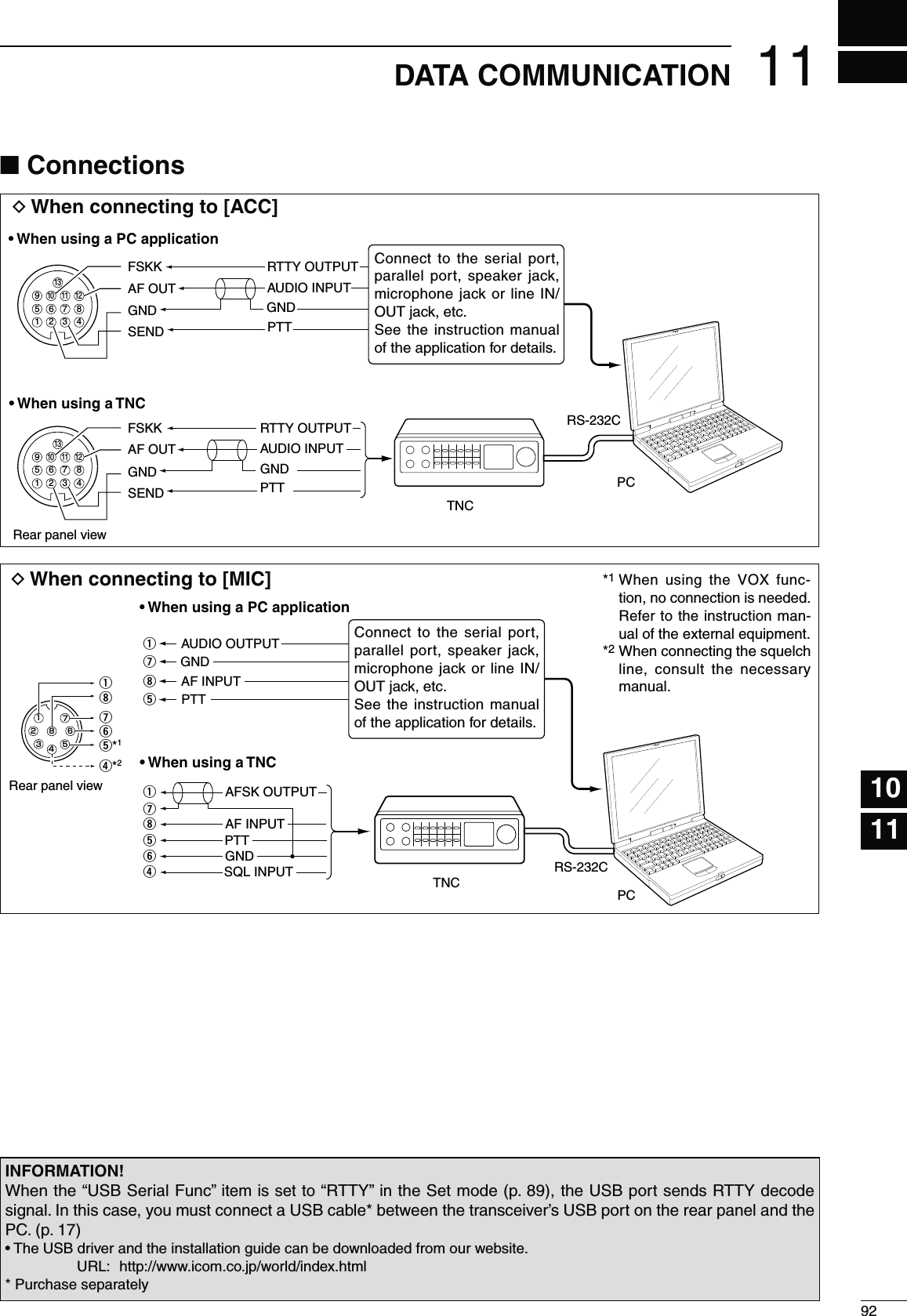
![93DATA COMMUNICATION11N0ACKET!&3+OPERATIONBefore operating packet (AFSK), be sure to consult the operating manual that came with your TNC.q Connect the TNC and PC. (p. 92)w Select the desired band. (p. 25)e Push [SSB] or [AM/FM] to select the desired oper-ating mode.r Hold down the same key you pushed in step e for 1 second to select the Data mode.t Rotate [DIAL] to select the desired frequency.y Transmit your AFSK signals using your PC’s key-board. s2OTATETHE;2&072=CONTROLTOSETTHEOUTPUTPOWERs7HILEUSINGA4.#THERELATIVESTRENGTHOFTHETRANSMIT-ted signal is indicated on the Po meter.s7HENOPERATINGINTHE33"DATAMODEADJUSTTHEOUT-put power so that the ALC meter reading stays in the ALC zone../4% When connecting the TNC to the ACC socket on the rear panel, select the USB, LSB, AM and FM data mode, or disconnect the microphone and ro-tate the [MIC] control fully counterclockwise.When the SSB data mode is selected, the audio input from the [MIC] connector is automatically cut, and the audio input from the [ACC] socket is used.Also, when the SSB data mode is selected, the fixed settings listed below are automatically selected;s3PEECHCOMPRESSOR /&&s4RANSMITBANDWIDTH -)$(Fixed to the default value; 300 Hz to 2700 Hz.)s4XTONE"ASS s4XTONE4REBLE s%XAMPLELSB/LSB data modeMark freq.: 2125 HzShift freq.: 200 Hz2325 Hz200 Hz 2125 HzCarrier point(Displayed frequency)When operating AFSK in the SSB mode, the displayed frequency is the signal’s carrier point.D&REQUENCYDISPLAYDURING!&3+OPERATIONAppears when the data mode is selected.[AM/FM] [DIAL][SSB]](https://usermanual.wiki/ICOM-orporated/318200/User-Guide-1398232-Page-100.png)
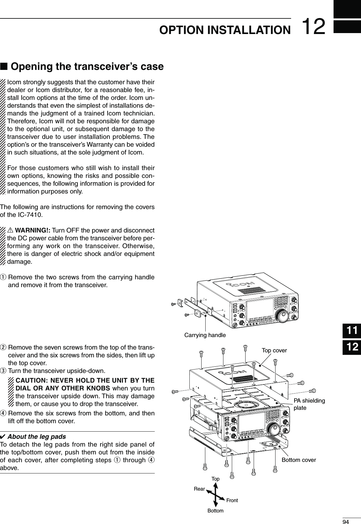
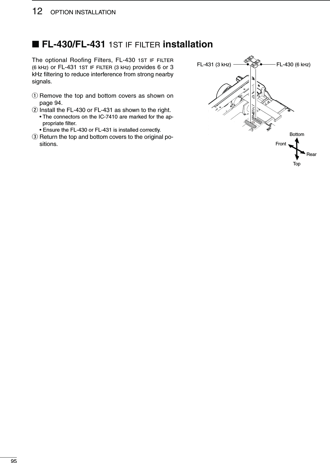
![96123456789101114151618192021MAINTENANCE17131213D4RANSCEIVERPOWER02/",%- 0/33)",%#!53% SOLUTION REF.Power does not turn ON when the [POWER] switch is pushed.s4HEPOWERCABLEISIMPROPERLYCONNECTEDs!FUSEISBLOWNs2ECONNECTTHE$#POWERCABLECORRECTLYs#ORRECTTHECAUSETHENREPLACE THEFUSEWITHan equivalent fuse. ( Fuses are installed in the DC power cable and in the internal PA unit.)p. 19p. 99D4RANSMITANDRECEIVE02/",%- 0/33)",%#!53% SOLUTION REF.No sound from the speaker. s4HEAUDIOVOLUMELEVELISTOOLOWs4HESQUELCHISCLOSEDs4HETRANSCEIVERISINTRANSMITs2OTATE THE ;!&= CONTROL CLOCKWISE TO OBTAIN Asuitable listening level.s2OTATETHE;2&31,=CONTROLTOOCLOCKPO-sition to open the squelch.s0USH ;42!.3-)4= TO RECEIVE OR CHECK THESEND line of an external unit, if connected.p. 31p. 32p. 34Sensitivity is too low, and only strong signals are audible.s4HEANTENNAISNOTCONNECTEDPROPERLYs4HEANTENNAFORANOTHERBANDISSELECTEDs4HEANTENNAISNOTPROPERLYTUNEDs4HEATTENUATORISTURNED/.s2ECONNECTTOTHEANTENNACONNECTORs3ELECT AN ANTENNA SUITABLE FOR THE OPERATINGfrequency.s(OLDDOWN;45.%2=FORSECONDTOMANUALLYtune the antenna.s0USH ;0!-0!44= TO SELECT TO TURN /&& THEattenuator.—p. 82p. 83p. 55Received audio is unclear or distorted.s4HEOPERATINGMODEISNOTMATCHEDs4HE0ASSBAND4UNINGFUNCTIONISTURNED/.s4HE.OISE"LANKERFUNCTIONISTURNED/.WHENreceiving a strong signal.s0REAMPLIlERISTURNED/.s4HE .OISE 2EDUCTION FUNCTION IS TURNED /.and the [NR] control is too far clockwise.s3ELECTASUITABLEOPERATINGMODEs(OLD DOWN ;0"4#,2= FOR SECOND TO RESETthe function.s0USH;."=TOTURN/&&THEFUNCTIONs0USH;0!-0!44=ONCEORTWICETOTURN/&&the function.s3ETTHE;.2=CONTROLFORMAXIMUMREADABILITYp. 31p. 59p. 60p. 55p. 61;!.4s-%4%2= DOES NOT FUNC-tions4HE!NTENNA3WITCHFUNCTIONISSETTOh/&&v s3ET THE !NTENNA 3WITCH FUNCTION TO h!UTOv OR“Manual” in the Set mode.p. 87Transmitting is impossible. s4HE OPERATING FREQUENCY IS OUTSIDE THE SE-lected ham band.s3ET THE FREQUENCY TO BE WITHIN THE SELECTEDham band.p. 26Output power is too low. s4HE ;2& 072= CONTROL IS SET TOO FAR COUNTER-clockwise.s4HE ;-)#= CONTROL IS SET TOO FAR COUNTERCLOCK-wise.s4HEANTENNAFORANOTHERBANDISSELECTEDs4HEANTENNAISNOTPROPERLYTUNEDs2OTATETHE;2&072=CONTROLCLOCKWISEs3ETTHE;-)#=CONTROLTOASUITABLEPOSITIONs3ELECT AN ANTENNA SUITABLE FOR THE OPERATINGfrequency.s(OLDDOWN;45.%2=FORSECONDTOMANUALLYtune the antenna.p. 34p. 34p. 82p. 83No contact can be made with another station.s4HE2)4OR∂TX function is turned ON.s4HE3PLITFUNCTIONISTURNED/.s0USH;2)4=OR;∂TX] to turn OFF the function.s0USH;30,)4=TOTURN/&&THEFUNCTIONpp. 53, 65p. 66Transmit signal is unclear or distorted.s4HE;-)#=CONTROLISSETTOOFARCLOCKWISE s3ETTHE;-)#=CONTROLTOASUITABLEPOSITION p. 34Repeater cannot be accessed. s4HE3PLITFUNCTIONISNOTTURNED/.s4HE PROGRAMMED SUBAUDIBLE TONE FREQUENCYis wrong.s0USH;30,)4=TOTURN/.THEFUNCTIONs2ESETTHEFREQUENCYUSINGTHE3ETMODEp. 66p. 52N4ROUBLESHOOTINGThe following chart is designed to help you correct problems which are not equipment malfunctions.If you are unable to locate the cause of a problem, or solve it through the use of this chart, contact your nearest Icom Dealer or Service Center.](https://usermanual.wiki/ICOM-orporated/318200/User-Guide-1398232-Page-103.png)
![9713 MAINTENANCEN Troubleshooting (continued)D3CANNING02/",%- 0/33)",%#!53% SOLUTION REF.A programmed scan does not stop.s3QUELCHISOPEN s3ET THE ;2&31,= CONTROL TO THE THRESHOLDpoint.p. 32A programmed scan does not start.s The same frequencies are programmed into the Scan Edge Memory channels “P1” and “P2.”s0ROGRAM DIFFERENT FREQUENCIES INTOthe Scan Edge Memory channels “P1” and “P2.”p. 70A memory scan does not start. s4WOORMOREMEMORYCHANNELSHAVENOTBEENprogrammed.s0ROGRAMMORETHANTWOMEMORYCHANNELS p. 70A select memory scan does not start.s4WOORMOREMEMORYCHANNELSHAVENOTBEENdesignated as select channels.s$ESIGNATEMORETHANTWOMEMORYCHANNELSASselect channels for the scan.p. 80A ∂F scan does not start. s4HE CENTER FREQUENCY FOR THE ∂F scan is not programmed.s0ROGRAMTHECENTERFREQUENCYFORTHE∂F scan. p. 81D$ISPLAY02/",%- 0/33)",%#!53% SOLUTION REF.The displayed frequency does not change properly.s4HE$IAL,OCKFUNCTIONISTURNED/.s4HE3ETMODESCREENISSELECTEDs4HEINTERNAL#05HASMALFUNCTIONEDs0USH;,/#+=TURN/&&THEFUNCTIONs0USH[MENU] to exit the Set Mode.s2ESETTHE#05p. 61p. 85p. 100 The tuning tension of [DIAL] may be adjusted to suit your preference.The tension adjustment is located on the bottom side of the front panel. See the figure to the right.Slide the tension adjustment to a comfortable level while turning the dial continuously and evenly in one direction. DIALTuning tensionadjustmentLightFirmN$IALTUNINGTENSIONADJUSTMENT](https://usermanual.wiki/ICOM-orporated/318200/User-Guide-1398232-Page-104.png)
![9813MAINTENANCE123456789101112131415161718192021N&REQUENCYCALIBRATIONAPPROXIMATE[PBT-CLR] [][][][][][][][][DIAL]Ù 47 ÚOFFSET Calibration MarkerÙ48 Ú50%SET REF Adjusts#ALIBRATIONMARKERITEMs2%&!DJUSTITEMA very accurate frequency counter is required to cali-brate the frequency of the transceiver. However, a rough check may be performed by receiving radio sta-tion WWV, WWVH, or other standard frequency sig-nals.#!54)/. The IC-7410 has been thoroughly ad-justed and tested at the factory before being shipped. You should not have to re-calibrate it.q Push [SSB] once or twice to select the USB mode.w Push [PBT-CLR] for 1 second to clear the PBT set-tings and make sure that the RIT/∂TX function is turned OFF.e Set the frequency to the standard frequency station minus 1 kHz.s When receiving WWV or WWVH (at 15.000.00 MHz) as a standard frequency, set the operating frequency for 14.999.00 MHz. s/THERSTANDARDFREQUENCIESCANALSOBEUSEDr Hold down [MENU] for 1 second to enter the Set mode.t Push [Y](F-1) or [Z](F-2) to select “Calibration Marker.”y Rotate [DIAL] to turn ON the calibration marker. s!SIDETONEMAYBEHEARDu Push [Z](F-2) to select “REF Adjust.”i Rotate [DIAL] to adjust for a zero beat with the re-ceived standard signal.s:EROBEATMEANSTHATTWOSIGNALSAREEXACTLYTHESAMEfrequency, resulting in a single tone being heard.o Push [Y](F-1) to select “Calibration Marker.”!0 Rotate [DIAL] to turn OFF the calibration marker.!1 Push [MENU] to save, and exit the Set mode.The IC-7410 2-step protection function monitors the power amplifier temperature and activates when the temperature becomes extremely high.s2EDUCEDPOWERTRANSMISSIONHalves the transmit output power.“LMT” appears above the TX icon “ .” (p. 11)s4RANSMISSIONINHIBITDeactivates the transmitter.Even if you push [PTT] or [TRANSMIT], the TX indica-tor does not light.When the protector is activated, operate in only the stand-by or receive mode until the power amplifier cools down../4%$/./4turn OFF the transceiver power when the protector is ON, or the cooling fan will not function, and delay cooling the transceiver.N!BOUTPROTECTIONDISPLAYS](https://usermanual.wiki/ICOM-orporated/318200/User-Guide-1398232-Page-105.png)
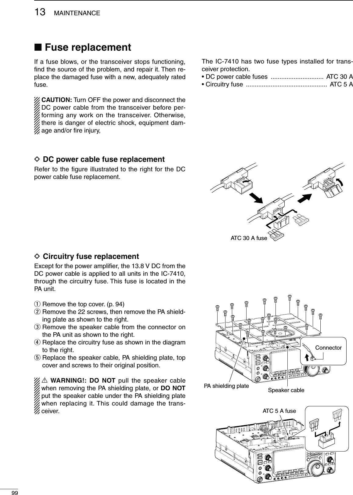
![10013MAINTENANCE123456789101112131415161718192021N2ESETTINGTHE#05D0ARTIALRESETIf you want to reset the operating parameters to their default values (VFO frequency, VFO settings, menu group’s contents) without clearing certain data as de-scribed below, a partial reset can be performed.The following data will not be cleared when doing a Partial reset:s-EMORYCONTENTSs-EMORYKEYERCONTENTSs0ROGRAMMEDUSERBANDEDGEFREQUENCIESs2%&!DJUST2EFERENCEFREQUENCYSETTINGq First, turn OFF the transceiver power.w While holding down [F-INP ENT] and [VFO/MEMO], push [POWER] to turn ON the power.s$URING STARTUP THE TRANSCEIVER DISPLAYS h0!24)!,RESET,” then the initial VFO frequencies when reset-ting is complete.s)FYOUOPERATETHETRANSCEIVERBEFOREh0!24)!,2%3%4vdisappears, the resetting will be cancelled.e If desired, edit the Set mode settings after resetting.D!LLRESETThe display may occasionally display erroneous infor-mation (e.g. when first applying power). This may be caused externally by static electricity or by other fac-tors.If this problem occurs, turn OFF the power. After wait-ing a few seconds, turn ON the power again. If the problem persists, perform the following procedure../4%Resetting the CPU CLEARS all programmed contents and returns them to their default settings.q First, turn OFF the transceiver power.w While holding down [F-INP ENT] and [M-CLR], push [POWER] to turn ON the power.s$URINGSTARTUPTHETRANSCEIVERDISPLAYSh!,,#,%!2vthen when resetting is complete, then displays the initial VFO frequencies.s)FYOUOPERATETHETRANSCEIVERBEFOREh!,,#,%!2vDIS-appears, the resetting will be cancelled.e If desired, edit the Set mode settings after resetting.[POWER] [F-INP ENT] [M-CLR][POWER] [F-INP ENT] [VFO/MEMO]](https://usermanual.wiki/ICOM-orporated/318200/User-Guide-1398232-Page-107.png)
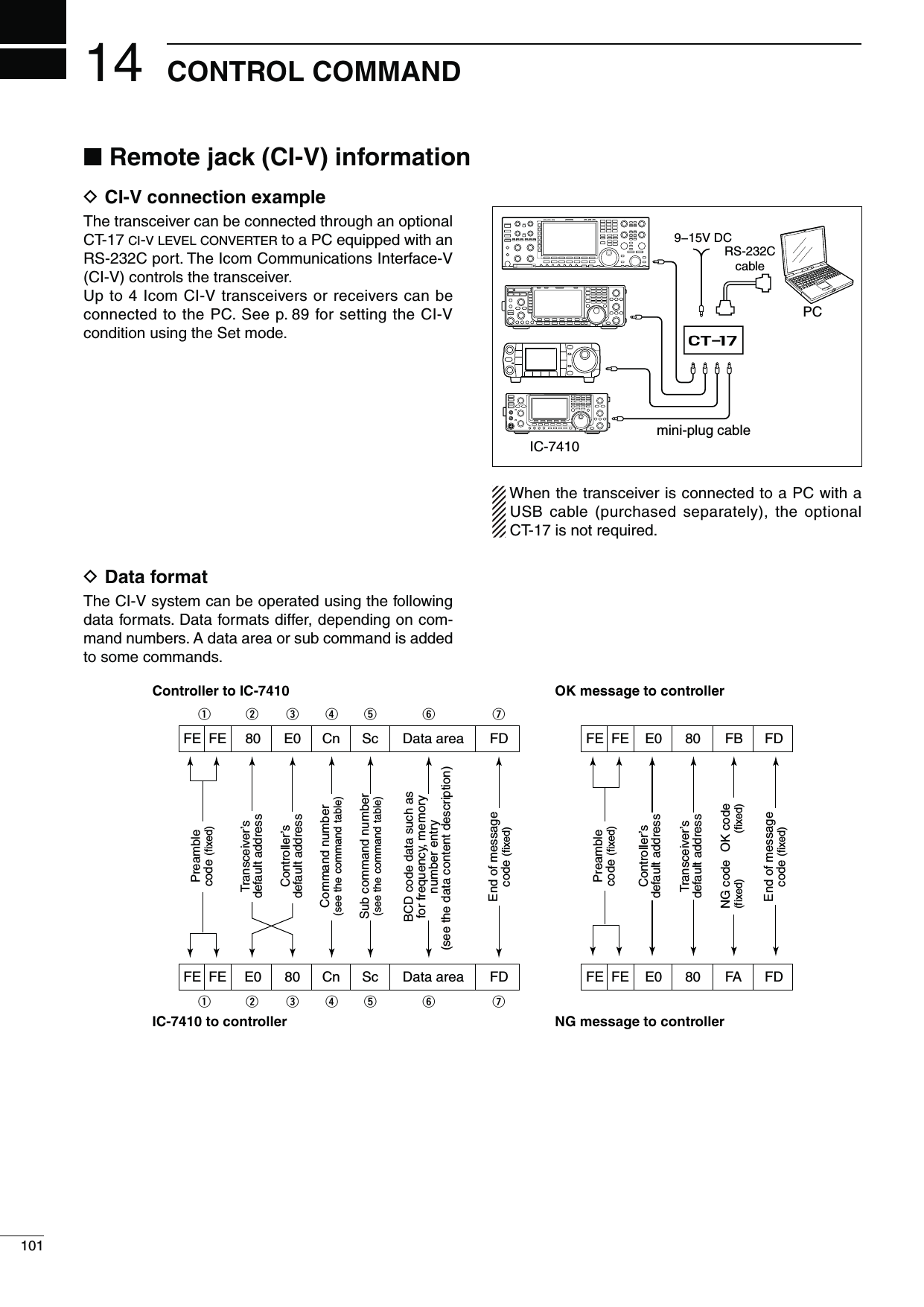
![102CONTROL COMMAND12345678910111213151617192021141814D#OMMANDTABLE#MD 3UBCMD Data $ESCRIPTION00 see p. 106 Send operating frequency for transceive01 see p. 106 Send operating mode for transceive02 see p. 106 Read band edge frequencies03 see p. 106 Read operating frequency04 see p. 106 Read operating mode05 see p. 106 Send operating frequency06 see p. 106 Send operating mode07 Select VFO mode00 Select VFO A01 Select VFO BA0 Equalize VFO A and VFO BB0 Exchange VFO A and VFO B08 Select Memory mode0001 to 0101Select memory channel( 0001=M-CH01 to 0099=M-CH99, 0100=P1, 0101=P2)09 Memory write0A Memory copy to VFO0B Memory clear0E 00 Scan stop01 Programmed/memory scan start02 Programmed scan start03 ∂F scan start12 Fine programmed scan start13 Fine ∂F scan start22 Memory scan start23 Select memory scan startA1 Set ∂F scan span ±5 kHzA2 Set ∂F scan span ±10 kHzA3 Set ∂F scan span ±20 kHzA4 Set ∂F scan span ±50 kHzA5 Set ∂F scan span ±100 kHzA6 Set ∂F scan span ±500 kHzA7 Set ∂F scan span ±1 MHzB0 Set as non-select channelB1 Set as select channelD0 Set scan resume OFFD3 Set scan resume ON0F Read Split function(00=OFF, 01=ON)00 Set the Split function OFF01 Set the Split function ON10 00 Send/read the tuning step 10 Hz (1 Hz)01 Send/read the tuning step 100 Hz02 Send/read the tuning step 1 kHz03 Send/read the tuning step 5 kHz04 Send/read the tuning step 9 kHz05 Send/read the tuning step 10 kHz06 Send/read the tuning step 12.5 kHz07 Send/read the tuning step 20 kHz08 Send/read the tuning step 25 kHz11 00 Send/read attenuator OFF20 Send/read 20 dB attenuator12 00 Send/read ANT1 selection00 Send/read ANT2 selection13 00 Announce operating frequency, operating mode and S-meter level with voice synthe-sizer01Announce operating frequency and S-meter level with voice synthesizer02 Announce operating mode with voice syn-thesizer#MD 3UBCMD Data $ESCRIPTION14 01 0000 to 0255Send/read [AF] position(0000=max. CCW, 0255=max. CW)02 0000 to 0255Send/read [RF] position(0000=max. CCW, 0255=11 o’clock)03 0000 to 0255Send/read [SQL] position(0000=11 o’clock, 0255=max. CW)06 0000 to 0255Send/read [NR] positionTO07 0000 to 0255Send/read inner [TWIN PBT] position( 0000=max. CCW, 0128=center, 0255=max. CW)08 0000 to 0255Send/read outer [TWIN PBT] position( 0000=max. CCW, 0128=center, 0255=max. CW)09 0000 to 0255Send/read [CW PITCH] position( 0000=300 Hz, 0128=600 Hz, 0255=900 Hz; 5 Hz steps)0A 0000 to 0255Send/read [RF PWR] position(0000=max. CCW to 0255=max. CW)0B 0000 to 0255Send/read [MIC] position(0000=max. CCW to 0255=max. CW)0C 0000 to 0255Send/read [KEY SPEED] position(0000=max. CCW to 0255=max. CW)0D 0000 to 0255Send/read [NOTCH] position( 0000=max. CCW, 0128=center, 0255=max. CW)0E 0000 to 0255Send/read [COMP] position(0000=max. CCW to 0255=max. CW)0F 0000 to 0255Send/read [BK-IN DELAY] position(0000=max. CCW to 0255=max. CW)12 0000 to 0255Send/read [NB] position(0000=max. CCW to 0255=max. CW)15 0000 to 0255Send/read [MONI GAIN] position(0000=max. CCW to 0255=max. CW)16 0000 to 0255Send/read VOX gainTO17 0000 to 0255Send/read Anti VOX gainTO18 0000 to 0255Send/read CONTRAST levelTO19 0000 to 0255Send/read BRIGHT levelTO15 01 00 Read squelch state (squelch close)01 Read squelch state (squelch open)02 0000 to 0255Read S-meter level(0000=S0, 0120=S9, 0241=S9+60 dB)11 0000 to 0255Read RF power meter12 0000 to 0255Read SWR meter( 0000=SWR1.0, 0041=SWR1.5, 0081=SWR2.0, 0120=SWR3.0)13 0000 to 0255Read ALC meter(0000=Min., 0120=Max.)14 0000 to 0255Read COMP meter(0000=0 dB, 0120=15 dB, 0240=30 dB)16 02 00 Send/read Preamp OFF01 Send/read Preamp 1 ON02 Send/read Preamp 2 ON12 01 Send/read AGC FAST02 Send/read AGC MID03 Send/read AGC SLOW22 00 Send/read Noise Blanker OFF01 Send/read Noise Blanker ON40 00 Send/read Noise Reduction OFF01 Send/read Noise Reduction ON41 00 Send/read Auto Notch function OFF01 Send/read Auto Notch function ON](https://usermanual.wiki/ICOM-orporated/318200/User-Guide-1398232-Page-109.png)
![103CONTROL COMMAND14D Command table (continued)#MD 3UBCMD Data $ESCRIPTION16 42 00 Send/read Repeater tone OFF01 Send/read Repeater tone ON43 00 Send/read Tone squelch OFF01 Send/read Tone squelch ON44 00 Send/read Speech Compressor OFF01 Send/read Speech Compressor ON45 00 Send/read Monitor function OFF01 Send/read Monitor function ON46 00 Send/read VOX function OFF01 Send/read VOX function ON47 00 Send/read BK-IN function OFF01 Send/read Semi BK-IN function ON02 Send/read Fill BK-IN function ON48 00 Send/read Manual Notch function OFF01 Send/read Manual Notch function ON4C 00 Send/read VSC function OFF01 Send/read VSC function ON4F 00 Send/read Twin Peak Filter OFF01 Send/read Twin Peak Filter ON50 00 Send/read Dial Lock function OFF01 Send/read Dial Lock function ON55 00 Send/read 1st IF filter 15 kHz01 Send/read 1st IF filter 6 kHz02 Send/read 1st IF filter 3 kHz56 00 Send/read DSP filter type SHARP01 Send/read DSP filter type SOFT57 00 Send/read manual notch width WIDE01 Send/read manual notch width MID02 Send/read manual notch width NAR58 00 Send/read SSB transmit bandwidth WIDE01 Send/read SSB transmit bandwidth MID02 Send/read SSB transmit bandwidth NAR17 see p. 107 Send CW messages19 00 Read the transceiver ID1A 00 see p. 108 Send/read memory contents01 see p. 106 Send/read band stacking register contents02 see p. 107 Send/read memory keyer contents03 00 to 49 Send/read the selected filter width( AM: 00=200 Hz to 49=10 kHz; other than AM modes: 00=50 Hz to 40/31=3600 Hz/2700 Hz)04 00 to 13 Send/read the selected AGC time constant( 00=OFF, AM: 01=0.3 sec. to 13=8.0 sec.; other than AM modes: 01=0.1 sec. to 13=6.0 sec.)05 0001 0000 to 0255Send/read LCD unit backlight brightness levelDARKTOBRIGHT0002 0000 to 0255Send/read LCD backlight brightness levelDARKTOBRIGHT0003 0000 to 0255Send/read beep levelTO0004 00 Send/read beep level limit OFF01 Send/read beep level limit ON0005 00 Send/read confirmation beep OFF01 Send/read confirmation beep ON0006 00 Send/read band edge beep OFF01 Send/read band edge beep ON(Beep sounds with a default band)02 Send/read band edge beep with user set-ting ON03 Send/read band edge beep with user set-ting/TX limit ON0007 0050 to 0200Send/read beep audio frequency(0050=500 Hz to 0200=2000 Hz)#MD 3UBCMD Data $ESCRIPTION1A 05 0008 00 Send/read Auto selection for [RF/SQL]01 Send/read SQL selection for [RF/SQL]02 Send/read RF+SQL selection for [RF/SQL]0009 00 Send/read Meter Peak Hold function OFF01 Send/read Meter Peak Hold function ON0010 00 Send/read Time-Out Timer (CI-V) OFF01 Send/read 3 min. Time-Out Timer (CI-V)02 Send/read 5 min. Time-Out Timer (CI-V)03 Send/read 10 min. Time-Out Timer (CI-V)04 Send/read 20 min. Time-Out Timer (CI-V)05 Send/read 30 min. Time-Out Timer (CI-V)0011 00 Send/read Quick Split function OFF01 Send/read Quick Split function ON0012 see p. 107 Send/read FM Split offset frequency (HF)0013 see p. 107 Send/read FM Split offset frequency(50 MHz)0014 00 Send/read Split Lock function OFF01 Send/read Split Lock function ON0015 00 Send/read Tuner Auto Start OFF01 Send/read Tuner Auto Start ON0016 00 Send/read PTT Tune OFF01 Send/read PTT Tune ON0017 00 Send/read antenna selection OFF01 Send/read manual antenna selection02 Send/read auto antenna selection0018 0000 to 0255Send/read voice synthesizer levelTO0019 00 Send/read English selection for voice syn-thesizer speech language01 Send/read Japanese selection for voice synthesizer speech language0020 00 Send/read speech speed slow01 Send/read speech speed fast0021 00 Send/read S-meter level announcement OFF01 Send/read S-meter level announcement ON0022 00 Send/read operating mode announcement (after pushing mode switch) OFF01 Send/read operating mode announcement (after pushing mode switch) ON0023 00 Send/read number of memo pad channels 501 Send/read number of memo pad channels 100024 00 Send/read auto TS for [DIAL] OFF01 Send/read auto TS for [DIAL] Low02 Send/read auto TS for [DIAL] High0025 00 Send/read Low selection for microphone Up/Down speed01 Send/read High selection for microphone Up/Down speed0026 00 Send/read Quick RIT/∂TX clear OFF01 Send/read Quick RIT/∂TX clear ON0027 00 Send/read Auto Notch selection for SSB01Send/read Manual Notch selection for SSB02 Send/read Auto/Manual Notch selection for SSB0028 00 Send/read Auto Notch selection for AM01 Send/read Manual Notch selection for AM02 Send/read Auto/Manual Notch selection for AM0029 00 Send/read manual notch filter width pop-up OFF01 Send/read manual notch filter width pop-up ON](https://usermanual.wiki/ICOM-orporated/318200/User-Guide-1398232-Page-110.png)
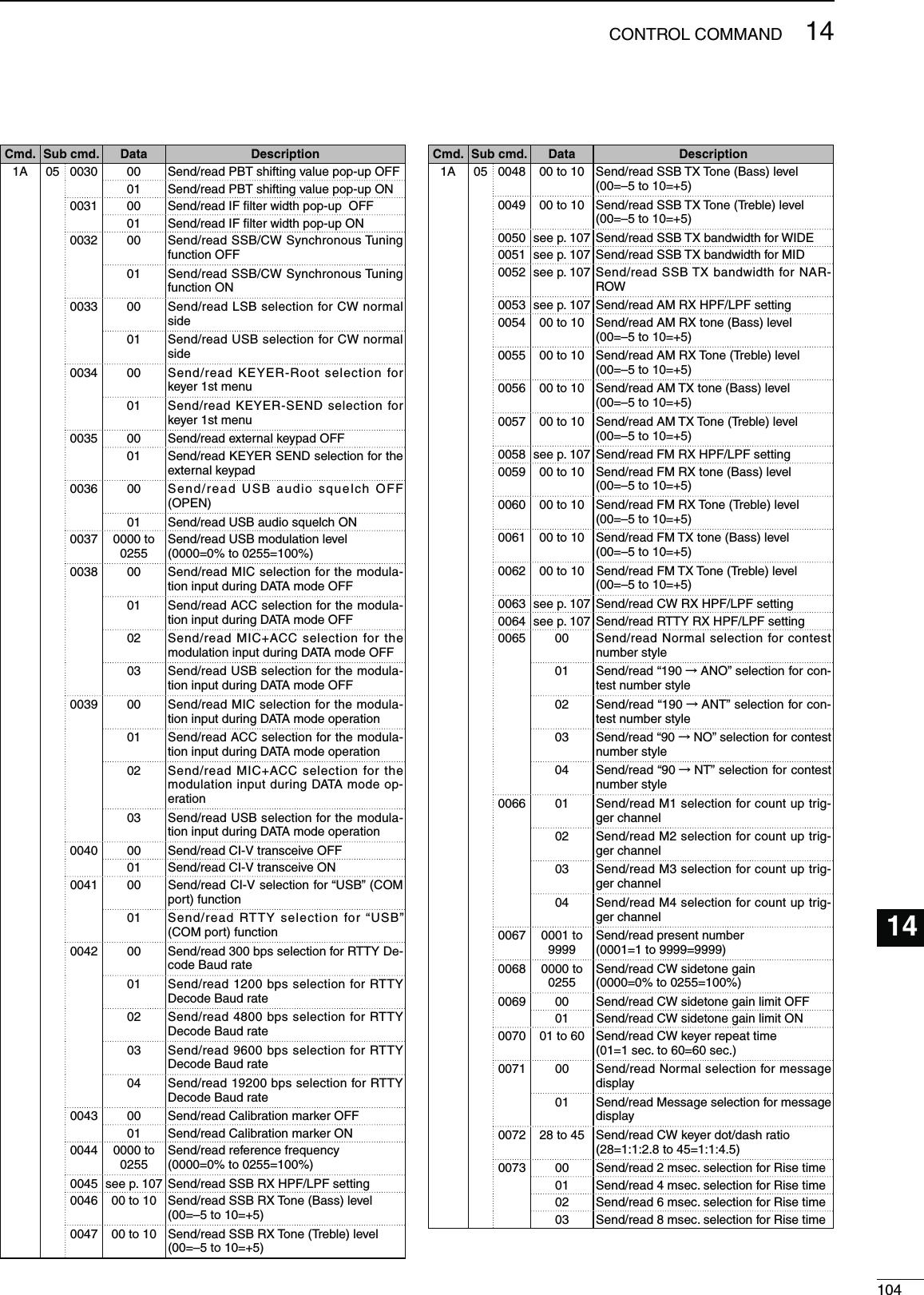
![106CONTROL COMMAND12345678910111213151617192021141814s#HARACTERCODESETTINGCommand : 1A 00 #HARACTER !3#))CODE #HARACTER !3#))CODEA–Z 41–5A a–z 61–7A0–9 30–39 Space 20!21#23$242526 <5C?3F " 22’27` 60^5E+2B–2D12A⁄2F.2E,2C: 3A;3B=3D<3C> 3E(28) 29[5B] 5D{7B} 7D¦7C_5F–7E@40s/PERATINGFREQUENCYCommand : 00, 03, 05qXXXXXweXrtXX XX10 Hz digit: 0–91 Hz digit: 0–91 kHz digit: 0–9100 Hz digit: 0–9100 kHz digit: 0–910 kHz digit: 0–910 MHz digit: 0–91 MHz digit: 0–91000 MHz digit: 0–1100 MHz digit: 0–4s/PERATINGMODECommand : 01, 04, 06qXXXXwq /PERATINGMODE w &ILTERSETTING00: LSB 03: CW 07: CW-R 01: FIL101: USB 04: RTTY 08: RTTY-R 02: FIL202: AM 05: FM 03: FIL3Filter setting (w) can be skipped with command 01 and 06. In that case, “FIL1” is automatically selected with command 01 and the default filter setting of the operating mode is selected with command 06.s"ANDEDGEFREQUENCYSETTINGCommand 02*, 1E 01, 1E 03qXXXwertyuio!0 !1 !2XXXXXXXXX2DXXXXXXXXXX10 Hz digit: 0–91 Hz digit: 0–91 kHz digit: 0–9100 Hz digit: 0–9100 kHz digit: 0–910 kHz digit: 0–910 MHz digit: 0–91 MHz digit: 0–91000 MHz digit: 0 (fixed)100 MHz digit: 0 (fixed)10 Hz digit: 0–91 Hz digit: 0–91 kHz digit: 0–9100 Hz digit: 0–9100 kHz digit: 0–910 kHz digit: 0–910 MHz digit: 0–91 MHz digit: 0–91000 MHz digit: 0 (fixed)100 MHz digit: 0 (fixed)Separator (fixed)Lower edge Higher edgeEdge number*: 01–30* Edge number setting is not necessary with com-mand 02.s"ANDSTACKINGREGISTERCommand : 1A 01qXXXXwq Frequency band code #ODE &REQBAND &REQUENCYRANGEUNIT-(Z01 1.8 1.800000– 1.99999902 3.5 3.400000– 4.09999903 7 6.900000– 7.49999904 10 9.900000–10.49999905 14 13.900000–14.49999906 18 17.900000–18.49999907 21 20.900000–21.49999908 24 24.400000–25.09999909 28 28.000000–29.99999910 50 50.000000–54.00000014 GENE Other than abovew Register code#ODE 2EGISTERED.O01 1 (latest)02 203 3 (oldest)For example, when reading the oldest contents in the 21 MHz band, the code “0703” is used.When sending the contents, the codes, such as op-erating frequency and operating mode*, should be added after the register code, as shown above.* See “Memory content setting (r to !7)” for details. (p. 108)D$ATACONTENTDESCRIPTION](https://usermanual.wiki/ICOM-orporated/318200/User-Guide-1398232-Page-113.png)
![111OPTIONS16AH-4 HF AUTOMATIC ANTENNA TUNERSpecially designed to tune a long wire antenna for HF/50 MHz bands partic-ularly in portable or mobile operation. The “PTT tune” function provides sim-ple operation.s)NPUTPOWERRATING7AH-2b ANTENNA ELEMENTA 2.5 m long antenna ele-ment for mobile operation with the AH-4.s&REQUENCY COVERAGE 7–54 MHz band with the AH-4SM-30 DESKTOP MICROPHONEUnidirectional, electret microphone for base station operation. Includes low cut switch and mic gain control.SM-50 DESKTOP MICROPHONEUnidirectional, dynamic microphone for base station operation. Includes [UP]/ [DOWN] switches, a low cut switch and mic gain control.SP-23 EXTERNAL SPEAKER4 audio filters; headphone jack; can connect to 2 transceivers.s)NPUTIMPEDANCEøs-AXINPUTPOWER7HM-36 HAND MICROPHONEHand microphone equipped with [UP]/[DOWN] switches.The same as that attached with the transceiver.IC-PW1/EURO HF/50 MHz ALL BAND 1 kW LINEAR AMPLIFIERFull-duty 1 kW linear amplifier including an automatic antenna tuner. Has auto-matic tuning and band selection capability. Full break-in (QSK) operation is pos-sible. The amplifier/power supply unit and the remote control unit are separated.The optional OPC-599 ADAPTER CABLE is required for connection.PS-126 DC POWER SUPPLY s/UTPUTVOLTAGE6$#s-AXOUTPUTCURRENT!N/PTIONSFL-430 1ST IF FILTER (6 kHz)FL-431 1ST IF FILTER (3 kHz)6 kHz or 3 kHz roofing filter can be used.The roofing filters reduce interfer-ence from strong nearby signals.SP-21 EXTERNAL SPEAKERDesigned for base station operation.s)NPUTIMPEDANCEøs-AXINPUTPOWER7CT-17 CI-V LEVEL CONVERTER UNITFor remote transceiver control using a personal computer equipped with an RS-232C port. You can change fre-quencies, operating mode, memory channels, etc., via your computer.](https://usermanual.wiki/ICOM-orporated/318200/User-Guide-1398232-Page-118.png)