ICOM orporated 318200 HF/50 MHz Tranceiver User Manual IC 7600 Instruction Manual
ICOM Incorporated HF/50 MHz Tranceiver IC 7600 Instruction Manual
User Manual
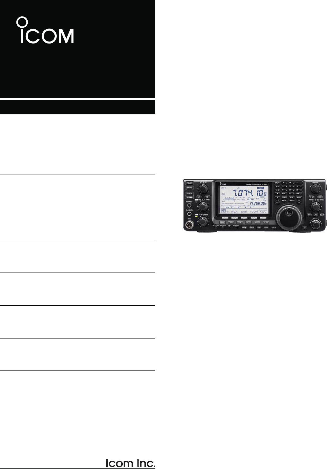
INSTRUCTION MANUAL
HF/50 MHz TRANSCEIVER
i7410
This device complies with Part 15 of the FCC Rules. Op-
eration is subject to the following two conditions: (1) this
device may not cause harmful interference, and (2) this
device must accept any interference received, including
interference that may cause undesired operation.
i
FOREWORD
Thank you for making the IC-7410 your radio of
choice. We hope you agree with Icom’s philosophy of
“technology first.” Many hours of research and devel-
opment went into the design of your IC-7410.
FEATURES
M High receiver performance: third-order intercept
(IP3) of +30 dBm (HF bands only)
M Simple band scope function
M ±0.5 ppm of high frequency stability
M Large LCD with LED backlight
M RS-BA1 compatible
IMPORTANT
READ THIS INSTRUCTION MANUAL
CAREFULLY before attempting to operate the
transceiver.
SAVE THIS INSTRUCTION MANUAL. This
manual contains important safety and operating
instructions for the IC-7410.
EXPLICIT DEFINITIONS
WORD DEFINITION
RDANGER! Personal death, serious injury or an
explosion may occur.
RWARNING! Personal injury, fire hazard or electric
shock may occur.
CAUTION Equipment damage may occur.
NOTE
If disregarded, inconvenience only. No risk
of personal injury, fire or electric shock.
Spurious signals may be received near some fre-
quencies.
These are made in the internal circuit and does not
indicate a transceiver malfunction.
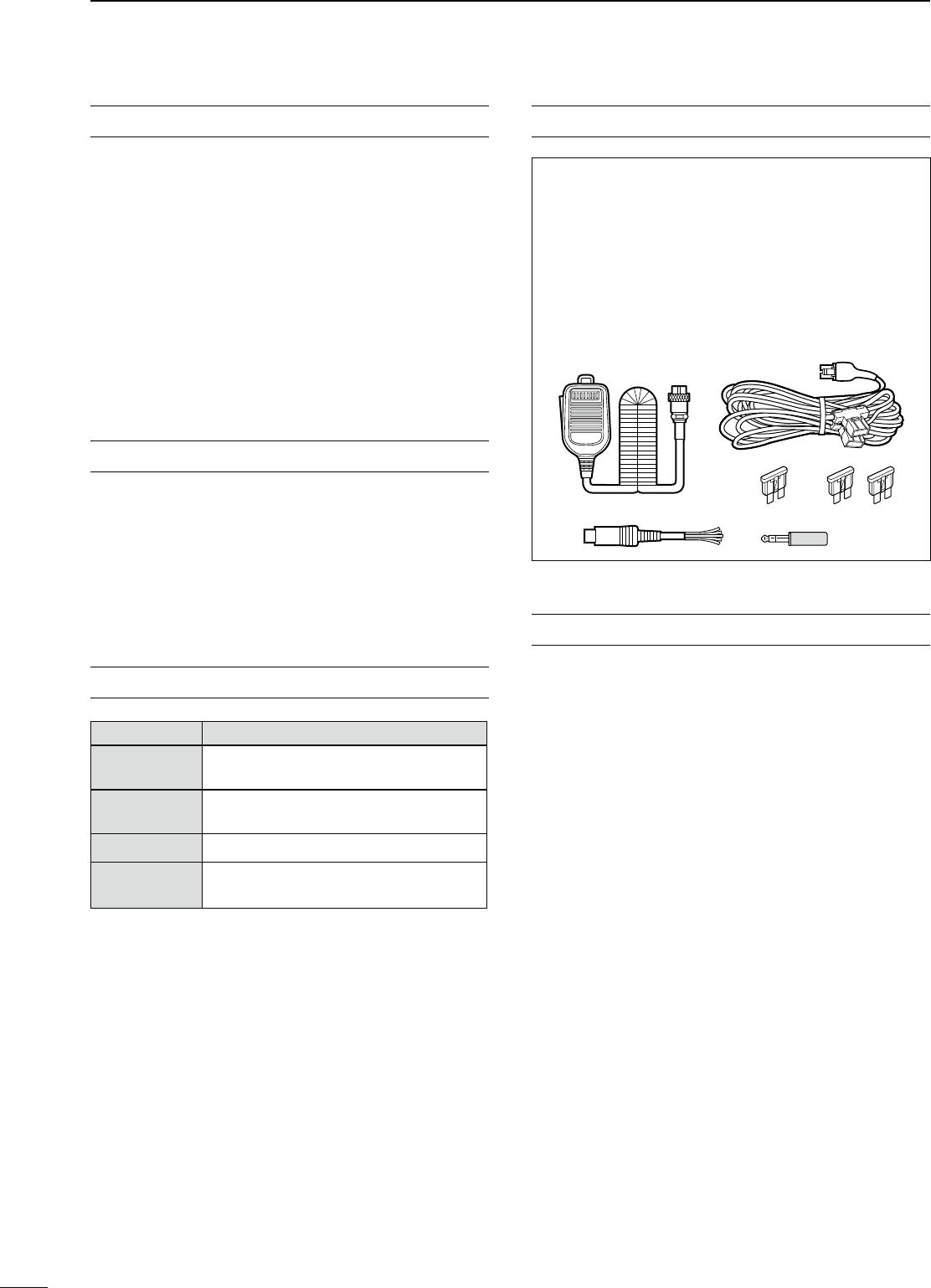
SUPPLIED ACCESSORIES
The transceiver comes with the following accessories.
Qty.
q Hand microphone ............................................ 1
w DC power cable ............................................... 1
e Spare fuse (ATC 5 A) ...................................... 1
r Spare fuse (ATC 30 A) .................................... 2
t ACC cable ......................................................... 1
y 6.3 (d) mm plug ................................................. 1
q
e
yt
w
r
FCC INFORMATION
s&/2#,!33"5.).4%.4)/.!,2!$)!4/23
This equipment has been tested and found to comply
with the limits for a Class B digital device, pursuant to
part 15 of the FCC Rules. These limits are designed
to provide reasonable protection against harmful
interference in a residential installation. This equip-
ment generates, uses and can radiate radio frequency
energy and, if not installed and used in accordance
with the instructions, may cause harmful interference
to radio communications. However, there is no guar-
antee that interference will not occur in a particular
installation. If this equipment does cause harmful
interference to radio or television reception, which can
be determined by turning the equipment off and on,
the user is encouraged to try to correct the interfer-
ence by one or more of the following measures:
s2EORIENTORRELOCATETHERECEIVINGANTENNA
s)NCREASETHESEPARATIONBETWEENTHEEQUIPMENT
and receiver.
s#ONNECTTHEEQUIPMENTINTOANOUTLETONA
circuit different from that to which the receiver is
connected.
s#ONSULTTHEDEALERORANEXPERIENCEDRADIO46
technician for help.
#!54)/. Changes or modifications to this device,
not expressly approved by Icom Inc., could void your
authority to operate this device under FCC regula-
tions.
Icom, Icom Inc. and the Icom logo are registered trademarks of
Icom Incorporated (Japan) in Japan, the United States, the United
Kingdom, Germany, France, Spain, Russia and/or other countries.
Microsoft, Windows and Windows Vista are registered trademarks
of Microsoft Corporation in the United States and/or other coun-
tries.
All other products or brands are registered trademarks or trade-
marks of their respective holders.

PRECAUTIONS
R WARNING HIGH RF VOLTAGE! NEVER
attach an antenna or internal antenna connector
during transmission. This may result in an electrical
shock or burn.
R WARNING! NEVER operate the transceiver
with a headset or other audio accessories at high
volume levels. Hearing experts advise against continu-
ous high volume operation. If you experience a ringing
in your ears, reduce the volume or discontinue use.
R WARNING! NEVER operate or touch the
transceiver with wet hands. This may result in an
electric shock or damage to the transceiver.
R WARNING! NEVER apply AC power to the
[DC13.8V] socket on the transceiver rear panel. This
could cause a fire or damage the transceiver.
R WARNING! NEVER apply more than 16 V
DC to the [DC13.8V] socket on the transceiver rear
panel, or use reverse polarity. This could cause a fire
or damage the transceiver.
R WARNING!
NEVER let metal, wire or other
objects protrude into the transceiver or into connectors
on the rear panel. This may result in an electric shock.
R WARNING! Immediately turn OFF the trans-
ceiver power and remove the power cable if it emits
an abnormal odor, sound or smoke. Contact your
Icom dealer or distributor for advice.
#!54)/. .%6%2 put the transceiver in any
unstable place (such as on a slanted surface or
vibrated place). This may cause injury and/or damage
to the transceiver.
#!54)/. NEVER change the internal settings of
the transceiver. This may reduce transceiver perfor-
mance and/or damage to the transceiver.
In particular, incorrect settings for transmitter circuits,
such as output power, idling current, etc., might
damage the expensive final devices.
The transceiver warranty does not cover any prob-
lems caused by unauthorized internal adjustment.
#!54)/. NEVER block any cooling vents on
the top, rear, sides or bottom of the transceiver.
#!54)/. NEVER expose the transceiver to
rain, snow or any liquids.
#!54)/.
NEVER install the transceiver in a
place without adequate ventilation. Heat dissipation
may be reduced, and the transceiver may be damaged.
DO NOT use harsh solvents such as benzine or
alcohol when cleaning, as they will damage the trans-
ceiver surfaces.
DO NOT push the PTT switch when you don’t actu-
ally desire to transmit.
DO NOT use or place the transceiver in areas with
temperatures below ±0°C (+32°F) or above +50°C
(+122°F).
DO NOT place the transceiver in excessively dusty
environments or in direct sunlight.
DO NOT place the transceiver against walls or
putting anything on top of the transceiver. This may
overheat the transceiver.
Always place unit in a secure place to avoid inadver-
tent use by children.
"% #!2%&5, If you use a linear amplifier, set
the transceiver’s RF output power to less than the
linear amplifier’s maximum input level, otherwise, the
linear amplifier will be damaged.
"% #!2%&5, The rear panel will become hot
when operating the transceiver continuously for long
periods of time.
USE only the specified microphone. Other manufac-
turers’ microphones have different pin assignments,
and connection to the IC-7410 may damage the
transceiver or microphone.
During maritime mobile operation, keep the trans-
ceiver and microphone as far away as possible from
the magnetic navigation compass to prevent errone-
ous indications.
Turn OFF the transceiver’s power and/or disconnect
the DC power cable when you will not use the trans-
ceiver for long period of time.
ii
1
2
3
4
5
6
7
8
9
10
11
12
13
14
15
16
17
18
19
20
21

iii
TABLE OF CONTENTS
FOREWORD .............................................................. i
IMPORTANT ............................................................... i
EXPLICIT DEFINITIONS ............................................ i
SUPPLIED ACCESSORIES....................................... i
FCC INFORMATION .................................................. i
PRECAUTIONS ......................................................... ii
4!",%/&#/.4%.43 ........................................... iii
1 PANEL DESCRIPTION................................... 1–14
N Front panel ........................................................ 1
N Rear panel ......................................................... 8
D ACC socket information .............................. 10
N LCD display ..................................................... 11
N Function display .............................................. 13
D M1 (Menu 1) ............................................... 13
D Function keys on M1 (Menu 1) ................... 13
D M2 (Menu 2) ............................................... 14
D Function keys on M2 (Menu 2) ................... 14
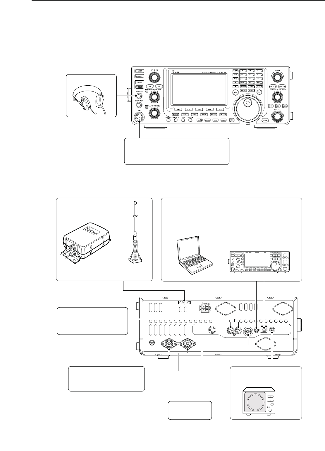
2 INSTALLATION AND CONNECTIONS ........ 15–22
N Selecting a location ......................................... 15
N Grounding ....................................................... 15
N Antenna connection ........................................ 15
N Required connections ..................................... 16
D Front panel .................................................. 16
D Rear panel .................................................. 16
N Advanced connections .................................... 17
D Front panel .................................................. 17
D Rear panel .................................................. 17
N External keypad connections .......................... 18
N External antenna tuner connection ................. 18
D Connecting the AH-4 .................................. 18
N Power supply connections ............................... 19
N Connecting to a DC power supply ................... 19
D Connecting to the PS-126 DC POWER
SUPPLY ...................................................... 19
D Connecting to a non-Icom DC POWER
SUPPLY ...................................................... 19
N Linear amplifier connections ........................... 20
D Connecting the IC-PW1/PW1EURO ........... 20
D Connecting a non-Icom linear amplifier ...... 21
N Microphone connector information .................. 22
N Microphones .................................................... 22
D HM-36 ........................................................ 22
D SM-50 (Option) ........................................... 22
3 "!3)#/0%2!4)/. ..................................... 23–34
N Before first applying power .............................. 23
N Turning ON (CPU resetting) ............................ 23
N VFO description ............................................... 24
D Selecting the VFO A/B ............................... 24
D VFO equalization ........................................ 24
N Selecting VFO/Memory mode ......................... 24
N Selecting a frequency band ............................. 25
D Using the band stacking registers. .............. 25
N Frequency setting ............................................ 26
D Tuning with [DIAL] ...................................... 26
D Direct frequency entry with the keypad ....... 26
D Quick Tuning function .................................. 27
D Selecting 1 Hz step ..................................... 27
D 1⁄4 Tuning Step function .............................. 27
D Auto Tuning Step function .......................... 28
D About the 5 MHz frequency band operation
(USA version only) ...................................... 28
D Band edge warning beep ............................ 29
D Programming the user band edge .............. 30
N Operating mode selection ............................... 31
N Volume setting ................................................. 31
N Squelch and receive (RF) sensitivity ............... 32
N Voice synthesizer operation ............................ 33
N Meter Display selection ................................... 33
N Basic transmit operation .................................. 34
D Transmitting ................................................. 34
D Microphone gain adjustment ....................... 34

iv
1
2
3
4
5
6
7
8
9
10
11
12
13
14
15
16
17
18
19
20
21
4 RECEIVE AND TRANSMIT .......................... 35–52
N Operating SSB ................................................ 35
N Operating CW ................................................. 36
D About the CW reverse mode ....................... 37
D About CW pitch control ............................... 37
D About keying speed..................................... 37
D CW sidetone function .................................. 37
N Electronic keyer functions ............................... 38
D Memory keyer menu construction ............... 38
D Memory keyer send menu........................... 39
D Editing a memory keyer .............................. 40
D Contest number Set mode .......................... 41
D Keyer Set mode .......................................... 42
N Operating RTTY (FSK) .................................... 44
N RTTY functions................................................ 45
D RTTY menu construction ............................ 45
D About the RTTY reverse mode ................... 46
D RTTY decoder ............................................. 46
D Twin Peak Filter ........................................... 47
D RTTY Set mode .......................................... 48
N Operating AM/FM ............................................ 49
N Tone squelch operation ................................... 50
N Tone scan operation ........................................ 51
N Repeater operation ......................................... 51
D Repeater access tone frequency setting ..... 52
D Transmit frequency monitor check .............. 52
5 FUNCTIONS FOR RECEIVE ........................ 53–61
N RIT function ..................................................... 53
D RIT monitor function .................................... 53
N Simple band scope .......................................... 54
N Preamplifier ..................................................... 55
N Attenuator ........................................................ 55
N AGC function ................................................... 56
D AGC speed selection .................................. 56
D Setting the AGC time constant .................... 56
N IF filter selection .............................................. 57
D IF filter selection .......................................... 57
D Filter passband width setting ...................... 57
D 1st IF filter selection .................................... 58
D IF (DSP) filter shape ................................... 58
N Twin PBT operation ......................................... 59
N Noise Blanker .................................................. 60
D NB Set mode ............................................... 60
N Meter Peak Hold function ................................ 60
N Noise Reduction .............................................. 61
N Dial Lock function ............................................ 61
N Notch function ................................................. 61
6 FUNCTIONS FOR TRANSMIT ..................... 62–68
N VOX function .................................................... 62
D Using the VOX function ............................... 62
D Adjusting the VOX function.......................... 62
N Break-in function ............................................. 63
D Semi Break-in operation ............................. 63
D Full Break-in operation ................................ 63
N Speech Compressor ....................................... 64
N
Transmit filter width selection ............................64
N ∂TX function ................................................... 65
D ∂TX Monitor function .................................. 65
N Monitor function ............................................... 65
N Split frequency operation ................................ 66
N Quick Split function ......................................... 67
D Split Lock function ....................................... 67
N Measuring SWR .............................................. 68
D Spot measurement ...................................... 68
D Plot measurement ....................................... 68

v
TABLE OF CONTENTS
7 MEMORY OPERATION ................................ 69–74
N General description ......................................... 69
D Memory channel contents ........................... 69
N Memory channel selection .............................. 69
D Selection in the VFO mode ......................... 69
D Selection in the Memory mode ................... 69
N Memory channel programming ....................... 70
D Programming in the VFO mode .................. 70
D Programming in the Memory mode ............. 70
N Memory clearing ............................................. 71
N Memory contents copying ............................... 72
D Copying in the VFO mode ........................... 72
D Copying in the Memory mode ..................... 72
NMemory name programming ........................... 73
NMemo Pad function ......................................... 74
D
Writing the displayed data into a memo pad
.. 74
D Calling up a memo pad ............................... 74
8 SCANS ......................................................... 75–81
N Scan types ...................................................... 75
N Preparation ...................................................... 76
N Voice Squelch Control function ....................... 76
N Scan Set mode ................................................ 77
N Programmed scan/Fine programmed scan
(VFO mode) .................................................... 78
D About the Fine programmed scan ............... 78
N Memory scan (Memory mode) ........................ 79
D Memory scan .............................................. 79
D Select Memory scan ................................... 80
D
Setting/Cancelling Select Memory channels
.80
N ∂F scan and Fine ∂F scan ............................. 81
D About the Fine ∂F scan .............................. 81
9 ANTENNA TUNER OPERATION ................. 82–84
N Antenna connection and selection .................. 82
N Antenna tuner operation .................................. 83
D Tuner operation ........................................... 83
D Manual tuning ............................................. 83
N Optional external tuner operation .................... 84
10 SET MODE ................................................... 85–91
N Set mode description ...................................... 85
D The Set mode settings ................................ 85
N Tone Control Set mode description ................. 90
D The Tone control Set mode settings ........... 90
11 DATA COMMUNICATION ............................. 92–93
N Connections .................................................... 92
D When connecting to [ACC].......................... 92
D When connecting to [MIC] .......................... 92
N Packet (AFSK) operation ................................. 93
D Frequency display during AFSK operation . 93
12 OPTION INSTALLATION ............................. 94–95
N Opening the transceiver’s case ....................... 94
N FL-430/FL-431 1ST IF FILTER installation .......... 95
13 MAINTENANCE ......................................... 96–100
N Troubleshooting ............................................... 96
D Transceiver power ....................................... 96
D Transmit and receive ................................... 96
D Scanning ..................................................... 97
D Display ........................................................ 97
N Dial tuning tension adjustment ........................ 97
N Frequency calibration (approximate) ............... 98
N About protection displays ................................ 98
N Fuse replacement ........................................... 99
D DC power cable fuse replacement .............. 99
D Circuitry fuse replacement .......................... 99
N Resetting the CPU ........................................ 100
D Partial reset ............................................... 100
D All reset ..................................................... 100

vi
1
2
3
4
5
6
7
8
9
10
11
12
13
14
15
16
17
18
19
20
21
14 CONTROL COMMAND ............................ 101–108
N Remote jack (CI-V) information ..................... 101
D CI-V connection example .......................... 101
D Data format ............................................... 101
D Command table ........................................ 102
D Data content description ........................... 106
15 SPECIFICATIONS .................................... 109–110
N General ......................................................... 109
N Transmitter .................................................... 109
N Receiver ........................................................ 110
N Antenna tuner ................................................ 110
16 OPTIONS .................................................. 111–112
N Options .......................................................... 111
17 CE ............................................................. 113–114
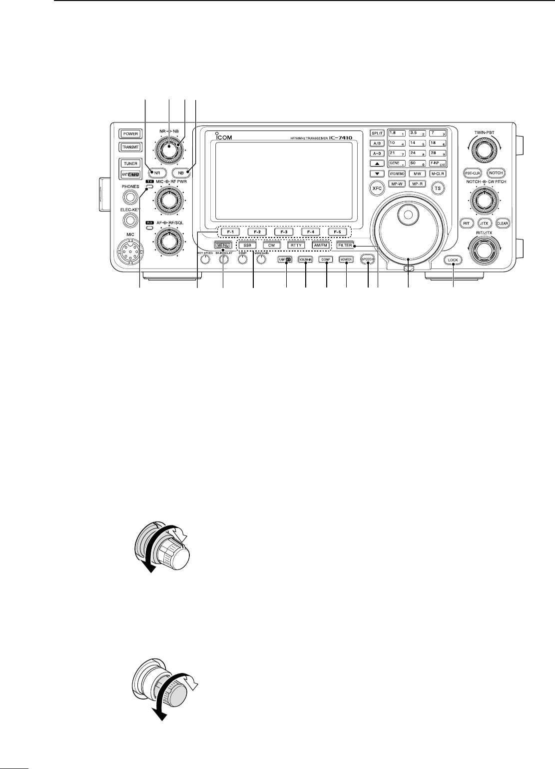
q POWER SWITCH [POWER] (p. 23)
± Push to turn ON the transceiver power.
s&IRSTCONlRMTHE$#POWERSOURCEISTURNED/.
± Hold down for 1 second to turn OFF the power.
w TRANSMIT SWITCH [TRANSMIT] (p. 34)
Push to select transmit or receive.
s7HILETRANSMITTINGTHE48INDICATOR@1) lights red.
s7HILERECEIVINGORWHENTHESQUELCHOPENSTHE28INDI-
cator (i) lights green.
e
ANTENNA TUNER SWITCH [TUNER] (pp. 83, 84)
± Push to turn the internal antenna tuner ON or
OFF (bypass).
s7HENTHETUNERIS/.h ” appears.
s4HEINTERNALANTENNATUNERSETTINGSCANBEMEMO-
rized in each frequency band.
± Hold down for 1 second to manually start the an-
tenna tuner.
s)FTHETUNERCANNOTTUNETHEANTENNAWITHINSEC-
onds, the tuning circuit is automatically bypassed.
r
!.4%..!s-%4%237)4#(;!.4s-%4%2=
ANTENNA SWITCH Operation
± Push to select either the ANT1 or ANT2 connec-
tor. (p. 82)
METER SWITCH Operation
± Hold down for 1 second to display either the
COMP or SWR meter in addition to the ALC
meter. (p. 33)
t HEADPHONE JACK [PHONES] (p. 17)
Plug in standard stereo headphones. Impedance: 8
to 16 ø.
s/UTPUTPOWERM7WITHANø load.
s7HENHEADPHONESARECONNECTEDTHEINTERNALSPEAKER
and any external speaker, are disabled.
y ELECTRONIC KEYER JACK [ELEC-KEY]
Plug in a bug or paddle type key to use the internal
electronic keyer for CW operation. (p. 16)
s3ELECTTHE%,%#+%9"5'+%9OR3TRAIGHTKEYKEYER
type in the “Keyer Type” item of the Keyer Set mode.
s!STRAIGHTKEYJACKISLOCATEDONTHEREARPANEL3EE
[KEY] on page 16.
s9OUCANREVERSE THE KEYERPADDLEPOLARITY DOT AND
dash) in the “Paddle Polarity” item of the Keyer Set
mode. (p. 42)
s&OURKEYERMEMORYCHANNELSAREAVAILABLEFORYOURCON-
venience. (p. 40)
(dot)
(com)
(dash)
u MICROPHONE CONNECTOR [MIC]
Plug in the supplied or optional microphone.
s3EEPAGEFORAPPROPRIATEMICROPHONESANDMICRO-
phone connector information.
i RX INDICATOR
Lights green while receiving or when the squelch
opens.
o AF CONTROL [AF] (inner control; p. 31)
Rotate to adjust audio output level to the speaker or
headphones.
N Front panel
1
1
PANEL DESCRIPTION
Increases
Decreases
t
i !4!3 !5 !6
y
e
r
u
!0
w
q
!2!1o
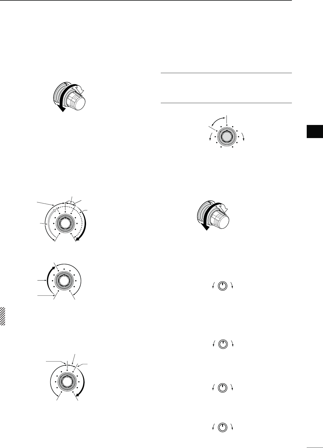
!0 RF GAIN CONTROL/SQUELCH CONTROL
[RF/SQL] (outer control; p. 32)
Rotate to adjust the RF gain and squelch threshold
level.
The squelch removes noise output to the speaker
when no signal is received (closed condition).
s4HESQUELCHIS PARTICULARLY EFFECTIVEIN&- BUT ALSO
works in other modes.
s4HETOOCLOCKPOSITIONISRECOMMENDEDfor the
most effective use of the [RF/SQL] control.
s;2&31,=OPERATESASONLYAN2&GAINCONTROLIN33"
CW and RTTY (Squelch is fixed open), or a squelch
control in AM and FM (RF gain is fixed at maximum
sensitivity), when the “RF/SQL Control” item is set to
“Auto” in the Set mode. (p. 86)
s7HENUSEDASAN2&GAINSQUELCHCONTROL
Maximum
RF gain
S-meter
squelch
Noise squelch (FM mode)
Squelch is
open.
RF gain
adjustable
range
Recommended level
s7HENUSEDASAN2&GAINCONTROL
(Squelch is fixed open; SSB, CW and RTTY only)
Minimum RF gain
Adjustable
range
Maximum
RF gain
While rotating the RF gain control, a faint noise may
be heard. This comes from the DSP unit and does
not indicate an equipment malfunction.
s7HENUSEDASASQUELCHCONTROL
(RF gain is fixed at maximum.)
Squelch is
open.
S-meter
squelch
S-meter squelch
threshold
Noise squelch
threshold
(FM mode)
Shallow Deep
Noise squelch (FM mode)
!1 MIC GAIN CONTROL [MIC] (inner control; p. 34)
Rotate to adjust the microphone gain.
s4HETRANSMITAUDIOTONEINTHE33"!-AND&-MODES
can be independently adjusted in the Tone Control Set
mode. (pp. 90, 91)
How to set the microphone gain.
While speaking at normal voice level, adjust the mi-
crophone gain so that in the SSB or AM modes, the
ALC meter swings within the ALC zone.
Recommended level for
Icom microphones
Increase
Decreases
!2 RF POWER CONTROL [RF PWR]
(outer control; p. 34)
Rotate to continuously vary the RF output power
between 2 W (minimum) and 100 W (maximum).
(AM: between 2 W and 27 W).
!3 ELECTRONIC CW KEYER SPEED CONTROL
[KEY SPEED] (p. 37)
-ODE#7
Rotate to adjust the keying speed of the internal
electronic CW keyer to between 6 wpm (minimum)
and 48 wpm (maximum).
FastSlow
!4"2%!+).$%,!9#/.42/,;"+).$%,!9=
(p. 63)
-ODE#7
Rotate to adjust the transmit-to-receive switching
delay time for the Semi Break-in function.
Long delay for
slow speed
keying
Short delay
for high speed
keying
!5 COMPRESSOR CONTROL [COMP] (p. 64)
-ODE33"
Rotate to adjust the compression level.
IncreasesDecreases
!6 MONITOR GAIN CONTROL [MONI GAIN] (p. 65)
Rotate adjust the monitor level for the clearest
audio output.
IncreasesDecreases
2
1
PANEL DESCRIPTION
1
2
3
4
5
6
7
8
9
10
11
12
13
14
15
16
17
18
19
20
21
!7./)3%",!.+%237)4#(;."= (p. 60)
± Push to turn the Noise Blanker ON or OFF. The
Noise Blanker reduces pulse-type noise such as
that generated by vehicle ignition systems. The
Noise Blanker cannot be used in the FM mode,
and is not effective for non-pulse-type noise.
sh."vAPPEARSWHENTHE.OISE"LANKERIS/.
± Hold down for 1 second to display the “NB”
screen. Push to return to the previous screen
display.
!8./)3%",!.+%2,%6%,#/.42/,;."=
(outer control; p. 60)
Rotate to adjust the noise blanker threshold level
when the Noise Blanker is ON. Set for maximum
readability.
s4OUSETHISCONTROLlRSTPUSH;."=!7).
Increases
Decreases
!9 NOISE REDUCTION LEVEL CONTROL [NR]
(inner control; p. 61)
Rotate to adjust the DSP noise reduction level
when the Noise Reduction is ON. Set for maximum
readability.
s4OUSETHISCONTROLlRSTPUSH;.2=@0).
Increases
Decreases
@0 NOISE REDUCTION SWITCH [NR] (p. 61)
Push to turn DSP Noise Reduction ON or OFF.
sh.2vAPPEARSWHEN.OISE2EDUCTIONIS/.
@1 TX INDICATOR
Lights red while transmitting.
@2 FUNCTION SWITCHES [F1]–[F5] (pp. 13, 14)
Push to select the function which is indicated on the
LCD display above each switch.
s4HEFUNCTIONSVARYDEPENDINGONTHESELECTEDMENU
and the operating mode.
@3 MENU SWITCH [MENU] (pp. 13, 14)
± Push to change the set of functions assigned to
switches ([F-1] to [F-5]).
s4OGGLESBETWEENTHEFUNCTIONMENUS--ENU
and M2 (Menu 2).
± Hold down for 1 second to enter the Set mode.
Push to return to the previous screen display.
@4 MODE SWITCHES
Push to select your desired operating mode. (p. 31)
s4HEBUILTINSPEECHSYNTHESIZERANNOUNCESTHESELECTED
mode when the “SPEECH [MODE] SW” item is set to
“ON” in the Set mode. (p. 87)
;33"=
± Push to alternately select the USB or LSB
modes.
sh53"vORh,3"vAPPEARS
± In the SSB mode, hold down for 1 second to se-
lect the SSB data mode (USB-D, LSB-D).
shD” appears in addition to “USB” or “LSB.”
± In the SSB data mode, push to return to the nor-
mal SSB mode.
[CW]
Push to alternately select the CW and CW-R (CW
reverse) modes.
sh#7vORh#72vAPPEARS
N Front panel (continued)
3
1PANEL DESCRIPTION
@1 @5 @6 @7 @8 @9 #1
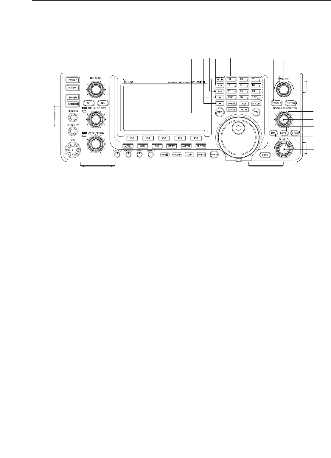
#0 #2
@0 !9 !8 !7
@4
@2 @3

[RTTY]
Push to alternately select the RTTY and RTTY-R
(RTTY reverse) modes.
sh2449vORh24492vAPPEARS
[AM/FM]
± Push to alternately select the AM or FM modes.
sh!-vORh&-vAPPEARS
± Hold down for 1 second to select the AM or FM
data mode (AM-D/FM-D).
shD” appears in addition to “AM” or “FM.”
± In the data mode, push to return to the normal
AM or FM mode.
@502%!-0s!44%.5!4/237)4#(;0!-0s!44=
PREAMP SWITCH Operation (p. 55)
Push to select one of two receive RF preamplifiers,
or to bypass them.
sh0!-0 ” is a wide dynamic range preamplifier. It is
most effective for the 1.8 to 21 MHz bands.
sh0!-0 ” is a high-gain preamplifier. It is most effec-
tive for the 24 to 50 MHz bands.
s.OINDICATORAPPEARSWHENTHEPREAMPLIlERSARENOTSE-
lected.
What is the preamplifier?
The preamplifier amplifies signals in the front end
to improve the S/N ratio and sensitivity. Select “P.
AMP ” or “P. AMP ” when receiving weak sig-
nals.
ATTENUATOR SWITCH Operation (p. 55)
± Hold down for 1 second to turn ON the attenua-
tor.
sh!44vAPPEARSWHENTHEATTENUATORIS/.
± Push to turn OFF the attenuator.
sh!44vDISAPPEARS
What is the attenuator?
The attenuator prevents a desired signal from being
distorted when very strong signals are near it, or
when very strong electromagnetic fields, such as
from a broadcasting station, are near your location.
@66/8"+).37)4#(;6/8"+).=
VOX SWITCH Operation (p. 62)
-ODE33"!-&-
± Push to turn the VOX function ON or OFF.
± Hold down for 1 second to display the “VOX”
screen. Push to return to the previous screen
display.
What is the VOX function?
The VOX function (voice operated transmission)
automatically starts transmission when you speak
into the microphone; then automatically returns to
receive when you stop speaking.
"+).37)4#( Operation (p. 63)
-ODE#7
Push to toggle the Break-in function between semi
break-in and full break-in, or to turn OFF the func-
tion.
What is the Break-in function?
The Break-in function automatically switches be-
tween transmit and receive with your CW keying.
Using the Full Break-in function (QSK), you can
hear the receive frequency in-between keying.
@7 COMPRESSOR SWITCH [COMP] (p. 64)
-ODE33"
Push to turn the Speech Compressor function ON
or OFF.
sh#/-0vAPPEARSWHENTHISFUNCTIONIS/.
@8 MONITOR SWITCH [MONITOR] (p. 65)
Push to turn the Monitor function ON or OFF to lis-
ten to your own transmitted audio.
sh-/.)vAPPEARSWHENTHISFUNCTIONIS/.
s)NTHE#7MODETHE#7SIDETONECANBEHEARDRE-
gardless of the [MONITOR] switch setting.
@9 SPEECH SWITCH [SPEECH] (p. 33)
± Push to audibly announce the S-meter level and
the displayed frequency.
± Hold down for 1 second to audibly announce the
S-meter level, the displayed frequency, and the
operating mode.
s4HE3,EVELANNOUNCEMENTCANBETURNED/&&INTHE
“SPEECH S-Level” item of the Set mode. (p. 87)
s7HEN2)4ANDOR∂TX are ON, the RIT/∂TX offset is
not included in the frequency announcement.
#0 FILTER SWITCH [FILTER] (p. 57)
± Push to select one of three IF filter settings ( / /
).
s4HESELECTEDlLTERPASSBANDWIDTHANDSHIFTINGVALUE
are displayed for 2 seconds on the LCD display.
± Hold down for 1 second to display the “FIL”
screen (Filter) to set the filter passband width.
Hold down for 1 second again to return to the
previous screen display.
#1 TUNING DIAL [DIAL] (p. 26)
Rotate to change the operating frequency, select
the Set mode settings, etc.
#2 LOCK SWITCH [LOCK] (p. 61)
Hold down for 1 second to turn the Dial Lock func-
tion ON or OFF.
s4HISFUNCTIONELECTRONICALLYLOCKS;$)!,=
sh ” appears when this function is ON.
4
1
PANEL DESCRIPTION
1
2
3
4
5
6
7
8
9
10
11
12
13
14
15
16
17
18
19
20
21
#3
TRANSMIT FREQUENCY CHECK SWITCH [XFC]
± During split frequency or repeater operation,
hold down to listen to the transmit frequency.
(pp. 52, 56)
s7HILEHOLDINGDOWN THIS SWITCHTHETRANSMIT FRE-
quency can be changed with [DIAL], keypad or
memo pad.
s7HENTHE3PLIT,OCKFUNCTIONISTURNED/.PUSH
[XFC] to cancel the Dial Lock function. (p. 67)
± When the RIT function is turned ON, hold down
to listen to the displayed frequency (RIT is
temporarily cancelled). (p. 53)
± When the ∂TX function is turned ON, hold down
to listen to the transmit frequency (including ∂TX
frequency offset). (p. 65)
#4 UP/DOWN SWITCHES [Y]/[Z]
± Push to change the operating channel. (p. 69)
± Hold down to continuously change the operating
channel.
#56&/%15!,):%37)4#(;!"= (p. 24)
Hold down for 1 second to equalize frequencies of
VFO A and B.
#66&/3%,%#437)4#(;!"= (p. 24)
Push to select either VFO A or VFO B to display.
sh6&/!vORh6&/"vISDISPLAYEDDEPENDINGONTHESE-
lection.
#7 SPLIT SWITCH [SPLIT]
± Push to turn the Split function ON or OFF. (p. 66)
sh30,)4vAPPEARSWHENTHE3PLITFUNCTIONIS/.
± Hold down for 1 second to activate the Quick
Split function.
(p. 67)
s4HETRANSMITFREQUENCYSHIFTSFROMTHERECEIVEFRE-
quency according to the “FM SPLIT Offset HF/50”
setting in the Set mode. (p. 86)
s4HE1UICK3PLITFUNCTIONCANBETURNED/&&INTHE
“Quick SPLIT” item of the Set mode. (p. 86)
#8"!.$+%93+%90!$
"!.$+%93/PERATION (p. 25)
± Push to select the operating band.
s;'%.s=SELECTSTHEGENERALCOVERAGEBAND
± Pushing the same key two or three times calls
up other stacked frequencies in the frequency
band.
s)COMSTRIPLEBANDSTACKINGREGISTERMEMORIZESTHREE
frequencies in each frequency band.
KEYPAD Operation (p. 26)
After pushing [F-INP ENT], push the keys on the
keypad to enter a frequency. After entering, push
[F-INP ENT] to set the frequency.
s%XAMPLETOENTER-(Z
0USH;&).0%.4=;=;=;s=;=;=;=;&).0%.4=
#90"4#,%!237)4#(;0"4#,2= (p. 59)
-ODE33"#72449!-
±Push to display the filter passband width and
shifting value for 2 seconds on the function dis-
play.
±Hold down for 1 second to reset the PBT set-
tings.
$00!33"!.$45.).'#/.42/,3;47).0"4=
(p. 59)
-ODE33"#72449!-
Adjusts the receiver’s IF filter passband width using
the DSP circuit.
sRotate this control or push [PBT-CLR] to display the
PBT settings (passband width and shifting value) for 2
seconds on the function display.
s(OLDDOWN;0"4#,2=FORSECONDTOCLEARTHE0"4
settings.
s4HEADJUSTMENTRANGEISHALFOFTHEPASSBANDWIDTHAND
the value is adjustable in 25 Hz steps in the SSB, CW,
and RTTY modes, and 100 Hz steps in the AM mode.
s4HESECONTROLSFUNCTIONASAN)&SHIFTCONTROL
N Front panel (continued)
5
1PANEL DESCRIPTION
#6 #7 #8#83 #4#5 #9 $0
$2
$3
$1
$5
$6
$4
$7
What is the PBT control?
The PBT function electronically modifies the IF passband
width to reject interference. This transceiver uses the
DSP circuit for the PBT function.
$1 NOTCH SWITCH [NOTCH] (p. 61)
-ODE!UTONOTCH 33"!-&-
-ANUALNOTCH33"#72449!-
± In the SSB and AM modes, push to toggle the
notch function between auto, manual and OFF.
s%ITHERTHE!UTOOR-ANUAL.OTCHFUNCTIONCANBE
turned OFF in the “[NOTCH] SW” item of the Set
mode. (p. 88)
± In the FM mode, push to turn the Auto Notch
function ON or OFF.
± In the CW or RTTY mode, push to turn the Man-
ual Notch function ON or OFF.
sh-.&vAPPEARSWHENTHE-ANUAL.OTCHFUNCTIONIS
ON.
sh!.&vAPPEARSWHENTHE!UTO.OTCHFUNCTIONIS/.
s.OICONAPPEARSWHENTHE.OTCHFUNCTIONIS/&&
± Hold down for 1 second to switch the manual
filter characteristics from wide, mid and narrow
when the Manual Notch function is selected.
What is the notch filter?
The notch filter is a narrow filter that eliminates unwanted
CW or AM carrier tones, while preserving the desired
voice signal. The DSP circuit automatically adjusts the
notch frequency to effectively eliminate unwanted tones.
$2 MANUAL NOTCH FILTER CONTROL [NOTCH]
(inner control; p. 61)
Rotate to adjust the notch frequency to reject an inter-
fering signal when the Manual Notch function is ON.
s.OTCHlLTERCENTERFREQUENCY
SSB/RTTY : –1040 Hz to +4040 Hz
CW : CW pitch freq. –2540 Hz to
CW pitch freq. +2540 Hz
AM : –5060 Hz to +5100 Hz
$3 CW PITCH CONTROL [CW PITCH]
(outer control; p. 37)
Rotate to shift the received CW audio pitch and the
CW sidetone pitch without changing the operating
frequency.
s4HEPITCHCANBEADJUSTEDFROMTO(ZINAP-
proximately 5 Hz steps.
$4 ∂TX SWITCH [∂TX] (p. 65)
± Push to turn the ∂TX function ON or OFF.
s5SETHE;2)4∂TX] control to vary the ∂TX frequency.
± Hold down for 1 second to shift the transmit fre-
quency up or down by the ∂TX frequency shift.
What is the ∂TX function?
∂TX shifts the transmit frequency without shifting the re-
ceive frequency. This is useful for simple split frequency
operation in CW, etc.
$5 CLEAR SWITCH [CLEAR] (pp. 53, 65)
Hold down for 1 second* to clear the RIT/∂TX fre-
quency shift.
* When the “Quick RIT Clear” item in the Set mode is set
to “ON,” push momentarily to reset the frequency shift.
(p. 88)
$6 RIT SWITCH [RIT] (p. 53)
± Push to turn the RIT function ON or OFF.
s5SE;2)4∂TX] control to vary the RIT frequency.
± Hold down for 1 second to shift the receive fre-
quency up or down by the RIT frequency shift.
What is the RIT function?
The RIT (Receiver Incremental Tuning) shifts the receive
frequency without shifting the transmit frequency.
This is useful for fine tuning stations calling you off-fre-
quency or when you prefer to listen to slightly different-
sounding voice characteristics, etc.
$7 RIT/∂TX CONTROL [RIT/∂TX] (pp. 53, 65)
When either or both the RIT/∂TX functions are ON,
rotate to adjust the RIT/∂TX frequency shift.
s2OTATETHECONTROLCLOCKWISETOINCREASETHEFREQUENCY
or counterclockwise to decrease the frequency.
s4HEFREQUENCYSHIFTRANGEISÒK(ZIN(ZSTEPS
The control tunes in 1 Hz steps when the operating fre-
quency readout is set to the 1 Hz step readout.
Shift high
Shift low
6
1
PANEL DESCRIPTION
1
2
3
4
5
6
7
8
9
10
11
12
13
14
15
16
17
18
19
20
21
Higher pitch
Lower pitch
Higher frequency
Lower frequency
PBT2
PBT1
–
+
Low cutHigh cut Center
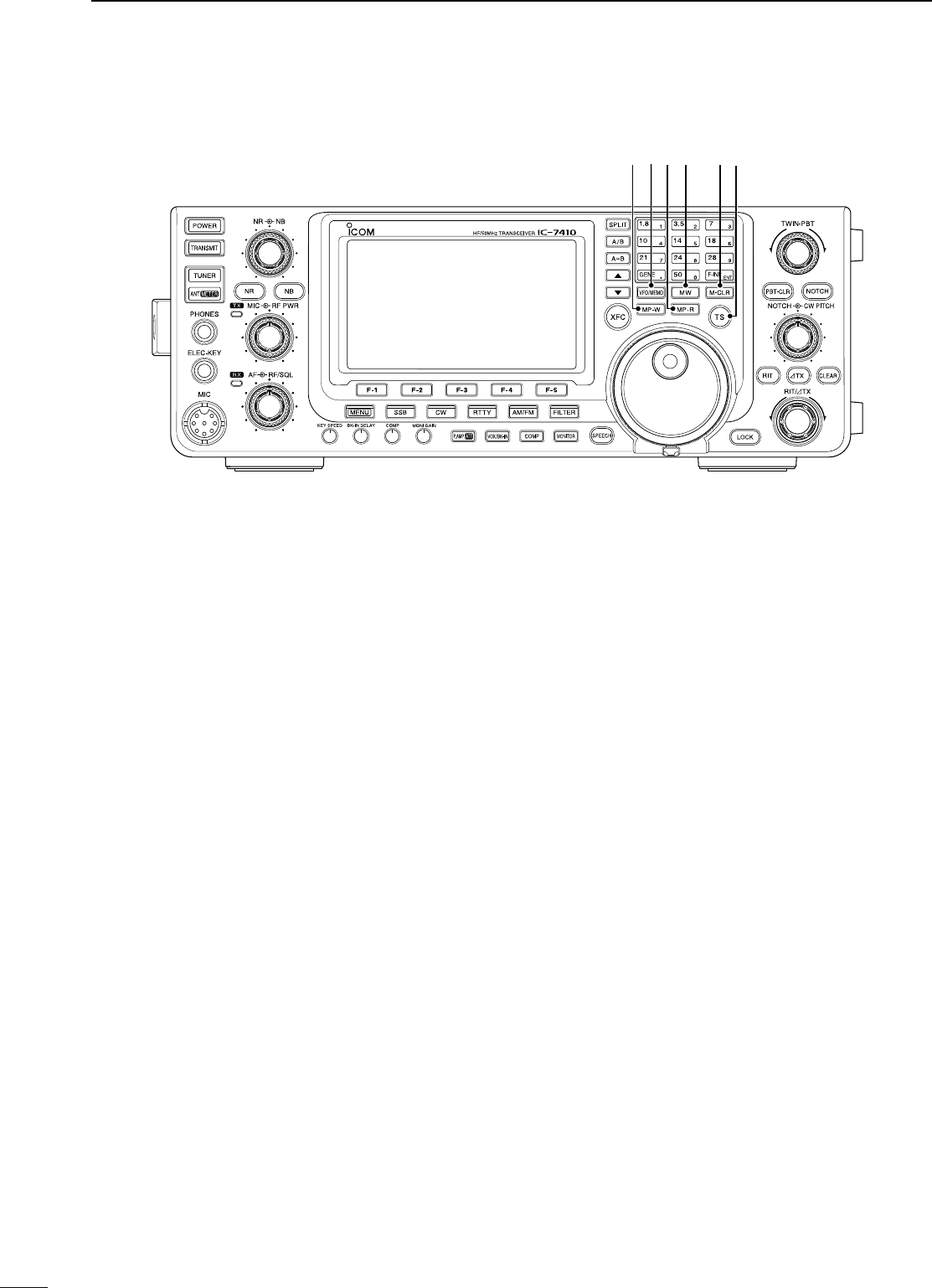
$8 MEMO PAD-WRITE SWITCH [MP-W] (p. 74)
Push to write the displayed data into a memo pad.
s4HElVEMOSTRECENTENTRIESREMAININTHEMEMOPADS
s4HEMEMOPADCAPACITYCANBEEXTENDEDFROM TO
10 in the “Memopad Numbers” item in the Set mode.
(p. 87)
$9 VFO/MEMORY SWITCH [VFO/MEMO]
± Push to switch between the VFO and Memory
modes. (p. 24)
± Hold down for 1 second to transfer the memory
contents to the displayed VFO. (p. 72)
%0 MEMO PAD-READ SWITCH [MP-R] (p. 74)
Push to sequentially call up the contents from the
memo pads.
The 5 (or 10) most recently programmed frequen-
cies and operating modes can be recalled, starting
from the most recent.
s4HEMEMOPADCAPACITYCANBEEXTENDEDFROMTO
10 in the “Memopad Numbers” item in the Set mode.
(p. 87)
%1 MEMORY WRITE SWITCH [MW] (p. 70)
Hold down for 1 second to store VFO data into the
selected memory channel.
s4HISCANBEDONEINBOTHTHE6&/ANDMEMORYMODES
%2 MEMORY CLEAR SWITCH [M-CLR] (p. 71)
In the Memory mode, hold down for 1 second to
clear the memory channel.
s4HECHANNELBECOMESABLANKCHANNEL
sThis switch is disabled in the VFO mode.
%3 TUNING STEP SWITCH [TS] (p. 27)
± Push to turn quick tuning step ON or OFF.
s7HENTHEh” quick tuning icon is displayed above
the kHz digit, the frequency is changed in selected
quick tuning steps.
s7HEN THE QUICK TUNING IS /&& THE FREQUENCY IS
changed in 10 Hz steps.
± When the quick tuning is ON, hold down for
1 second to display the “TS” screen (Tuning
Step) to select the quick tuning step.
sANDK(ZSTEPSAREINDE-
pendently selectable for each operating mode.
± When the quick tuning is OFF, hold down for
1 second to turn the minimum tuning step of
1 Hz ON or OFF.
N Front panel (continued)
7
1PANEL DESCRIPTION
$8 $9 %1 %3%2%0
8
1
PANEL DESCRIPTION
1
2
3
4
5
6
7
8
9
10
11
12
13
14
15
16
17
18
19
20
21
N Rear panel
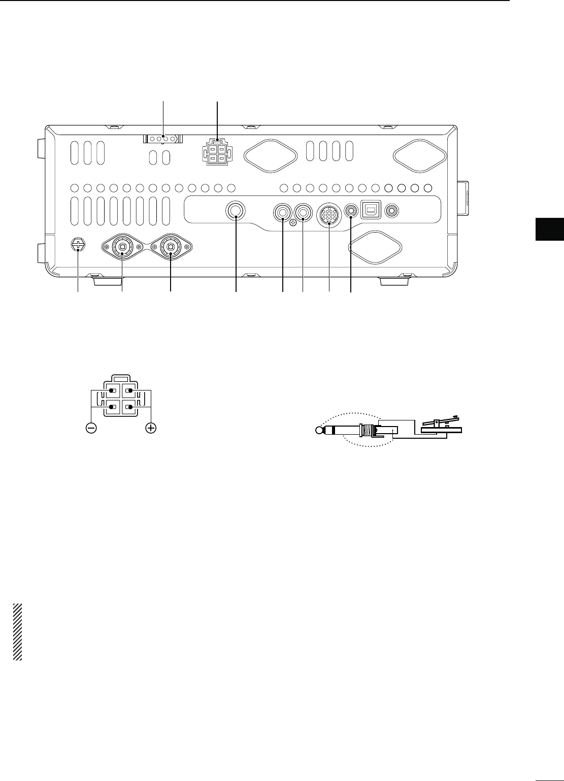
q DC POWER SOCKET [DC 13.8V] (p. 19)
Connect 13.8 V DC through the supplied DC power
cable.
Rear panel view
w TUNER CONTROL SOCKET [TUNER] (p. 18)
Connect the control cable from an optional AH-4 HF/
50 MHZ AUTOMATIC ANTENNA TUNER.
e GROUND TERMINAL [GND] (p. 15)
Connect this terminal to a ground to prevent electri-
cal shocks, TVI, BCI and other problems.
r ANTENNA CONNECTOR 1 [ANT1] (p. 16)
t ANTENNA CONNECTOR 2 [ANT2] (p. 16)
Connect a 50 ø antenna with a PL-259 plug con-
nector.
When using an optional AH-4 HF/ 50 MHZ AUTO-
MATIC ANTENNA TUNER, connect it to the [ANT1]
connector. Connecting the AH-4 activates the in-
ternal antenna tuner for [ANT2] and deactivates
it for [ANT1].
y STRAIGHT KEY JACK [KEY] (p. 16)
Connect a straight key or external electronic keyer
output using a standard 1⁄4 inch plug.
s;%,%#+%9= ON THE FRONT PANEL CAN BE USED FOR A
straight key or external electronic keyer. First you must
turn OFF the internal electronic keyer in the Keyer Set
mode. (p. 43)
(+)
(_)
u ALC INPUT JACK [ALC] (p. 21)
When transmitting, goes to ground to control an ex-
ternal unit, such as a non-Icom linear amplifier.
i SEND CONTROL JACK [SEND] (p. 21)
Connect a ground when transmitting to control an
external unit, such as a non-Icom linear amplifier.
o ACCESSORY SOCKET [ACC]
Connect control lines for external equipment such
as a linear amplifier, an automatic antenna selector/
tuner, a TNC for data communications, etc.
s3EEPAGEFORSOCKETINFORMATION
!0 CI-V REMOTE CONTROL JACK [REMOTE]
(p. 17)
± Connect
a PC, using the optional CT-17 CI-V
LEVEL CONVERTER, for external control of the trans-
ceiver.
± Use for transceive operation with another Icom
CI-V transceiver or receiver. When the trans-
ceive function is set to ON, changing the fre-
quency, operating mode, etc. on the IC-7410
automatically changes those settings on other
Icom transceivers or receivers, and vice versa.
(p. 89)
!0
tr io
u
y
e
wq
!153"5NIVERSAL3ERIAL"US#/..%#4/2
;53"=
Using a USB cable, connect a PC to do the follow-
ing:
- Input modulation (p. 89)
- Remotely control the transceiver using CI-V com-
mands (p. 101)
- Send the received audio to the PC
-
Send the decoded characters to the PC (p. 89)
!BOUTTHE53"DRIVER
The USB driver and the installation guide can be
downloaded from our website.
± http://www.icom.co.jp/world/index.html
The following items are required:
PC
s-ICROSOFT® Windows® XP,
Microsoft® Windows Vista® or
Microsoft® Windows® 7 OS
s!53"ORPORT
/THERITEMS
s53"CABLEPURCHASESEPARATELY
s0#SOFTWARESUCHASOPTIONAL23"!
./4%"%352%to install the USB driver "%-
FORE connecting the USB cable between the
radio and the PC. This is because the USB driver
does not support the automatic recognition sys-
tem.
!BOUTTHEMODULATIONINPUT
Select “USB” in the Set mode item “DATA OFF
MOD” or “DATA MOD.” The modulation input level
from the USB jack can be set in the Set mode item
“USB MOD Level.” (p. 89)
!2
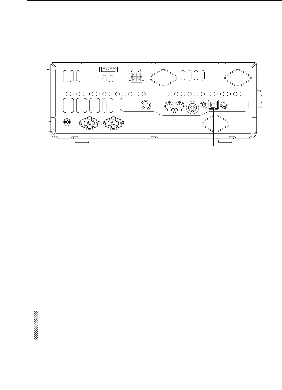
EXTERNAL SPEAKER JACK [EXT-SP]
(p. 17)
Connect an external speaker (4 to 8 ø).
9
1PANEL DESCRIPTION
!2
N Rear panel (Continued)
!1
10
1
PANEL DESCRIPTION
1
2
3
4
5
6
7
8
9
10
11
12
13
14
15
16
17
18
19
20
21
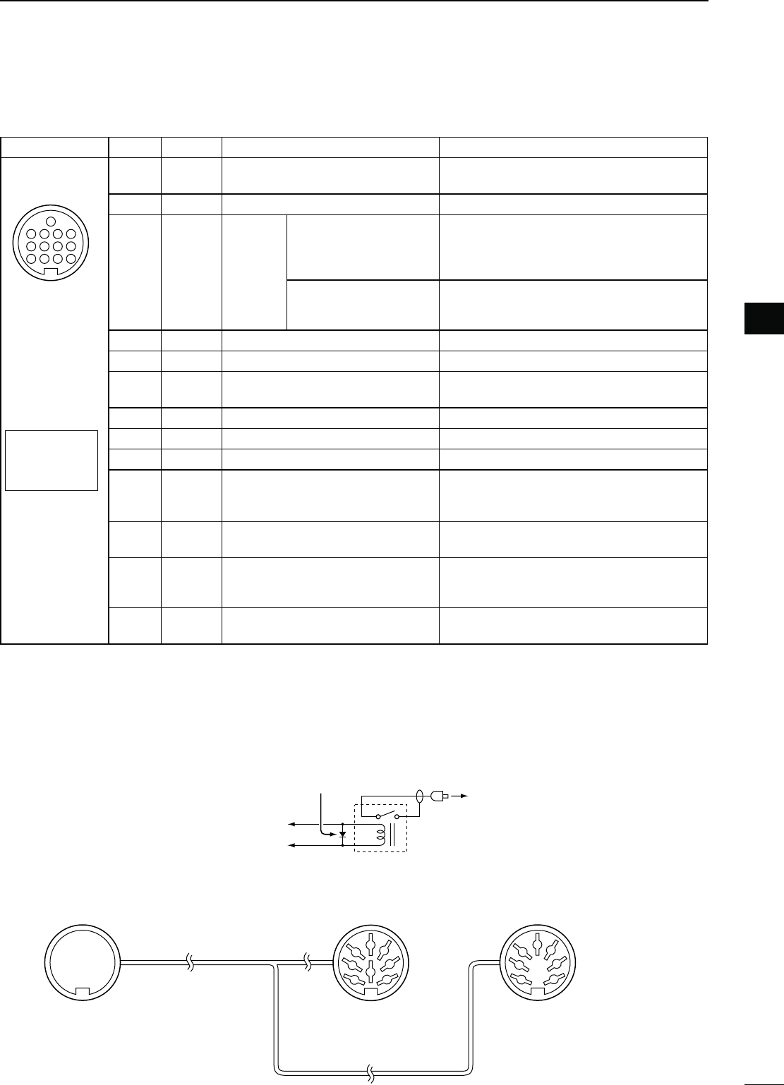
D!##SOCKETINFORMATION
s!##SOCKET
ACC
PIN No.
NAME DESCRIPTION SPECIFICATIONS
1234
8765
9
10 11 12
13
Rear panel view
Color refers to
the cable strands
of the supplied
cable.
q brown
w red
e orange
r yellow
t green
y blue
u purple
i
o
!0
!1
!2
!3
gray
white
black
pink
light
blue
light
green
18 V Regulated 8 V output. Output voltage
Output current
: 8 V ± 0.3 V
: Less than 10 mA
2 GND Connects to ground. ———
3
SEND*
Input/out-
put pin.
An external unit controls
the transceiver.
When this pin goes low,
the transceiver transmits.
Input voltage (High)
Input voltage (Low)
Current flow
: 2.0 V to 20.0 V
: –0.5 V to +0.8 V
: Max. 20 mA
The transceiver outputs
a low signal to control an
external unit.
Output voltage (Low)
Current flow
: Less than 0.1 V
: Max. 200 mA
4NC ——— ———
5 BAND Band voltage output. Output voltage : 0 V to 8 V
6 ALC ALC voltage input. Control voltage
Input impedance
: –3 V to 0 V
: More than 3.3 k˘
7 NC ——— ———
8 13.8 V 13.8 V output when power is ON. Output current : Less than 1 A
9 NC ——— ———
10 FSKK Controls RTTY keying
“High” level
“Low” level
Output current
: More than 2.4 V
: Less than 0.6 V
: Less than 2 mA
11 MOD Modulator input. Input impedance
Input level
: 10 k˘
: Approx. 100 mV rms
12 AF
AF detector output.
Fixed level, regardless of the [AF]
control position.
Output impedance
Output level
: 4.7 k˘
: 100 to 300 mV rms
13 SQL S Squelch output.
Grounded when squelch opens.
SQL open
SQL closed
: Less than 0.3 V/5 mA
: More than 6.0 V/100 μA
* When the SEND terminal controls an inductive load (such as a relay), a counter-electromotive force can cause
the transceiver’s malfunction or damage. To prevent this, we recommend adding a switching diode, such as an
“1SS133,” on the load side of the circuit to the counter-electromotive force absorption.
When the diode is added, a switching delay of the relay may occur. Be sure to check its switching action before
operation.
eSEND
i13.8 V
ACC
socket
Relay
Switching diode To a non-Icom
linear amplifier
[Example]
8
1
2
3
4
7
6
5
1
2
3
4
7
6
5
qwer
tyui
o!0 !1 !2
!3 Connect to ACC socket ACC 1 ACC 2
q FSKK
w GND
e SEND
r MOD
t AF
y SQL S
u 13.8 V
i ALC
q 8 V
w GND
e SEND
r BAND
t ALC
y NC
u 13.8 V
s7HENCONNECTINGTHE!##CONVERSIONCABLE/0#
11
1PANEL DESCRIPTION
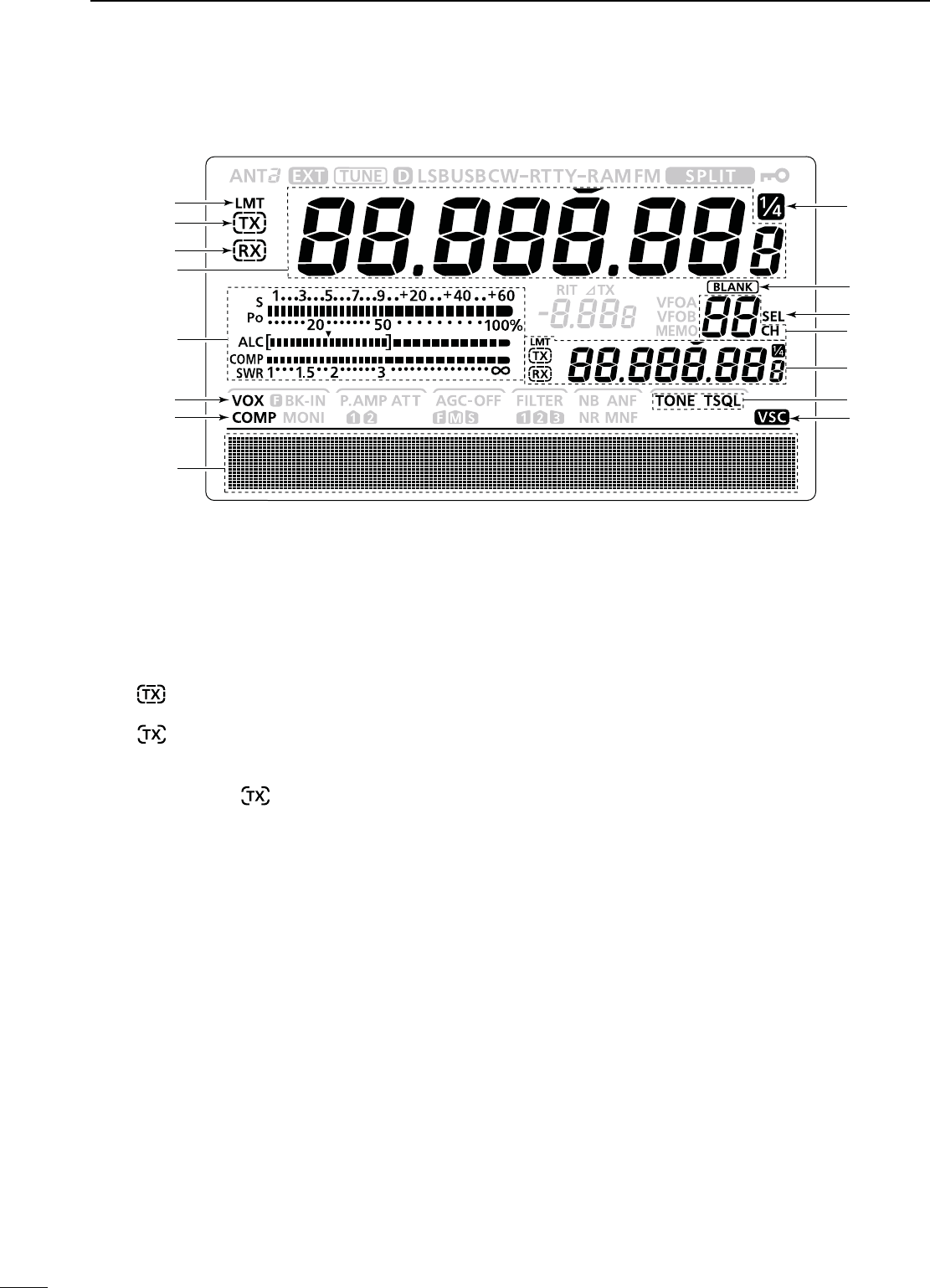
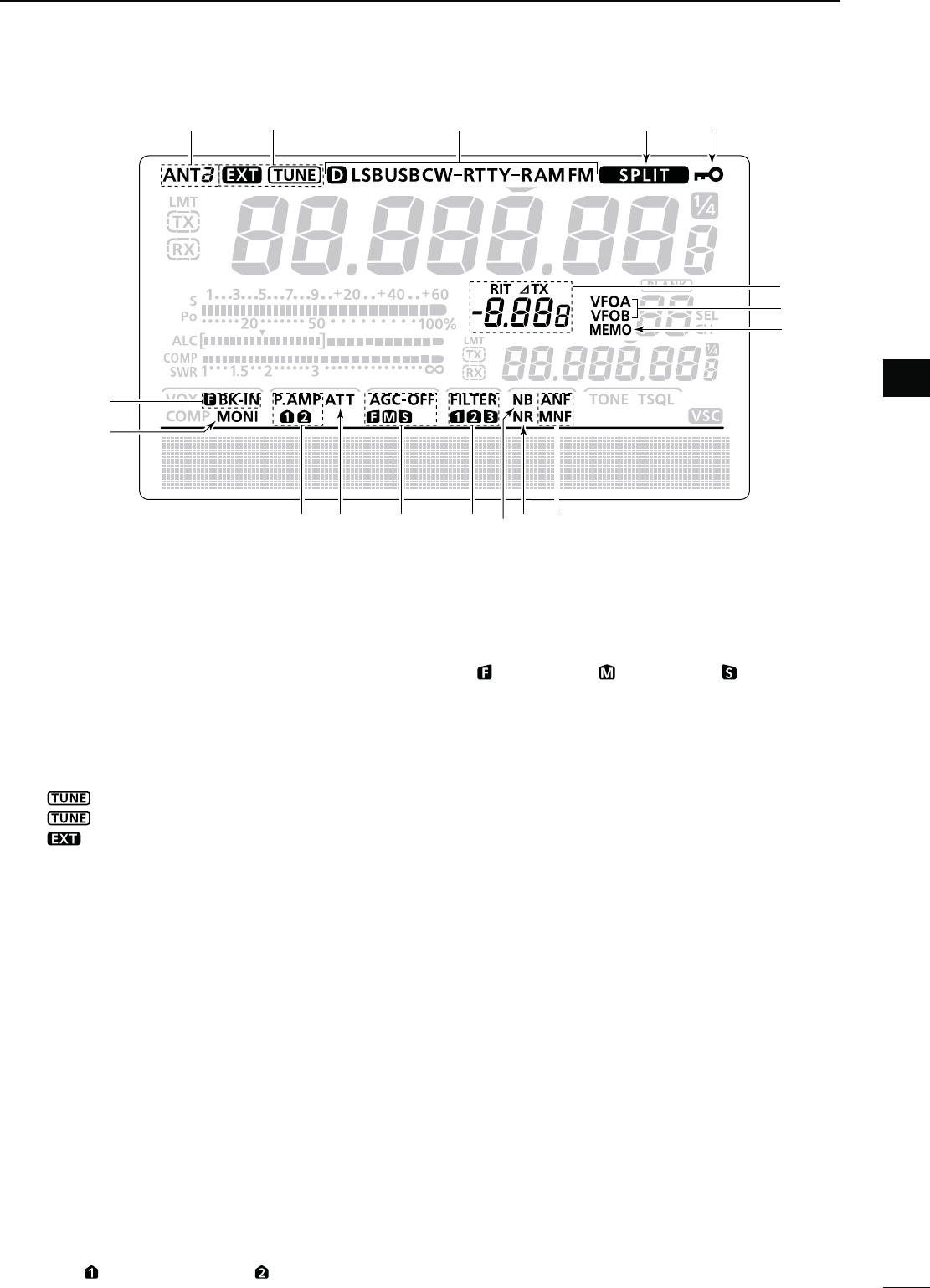
N,#$DISPLAY
q POWER DOWN TRANSMISSION ICON (p. 98)
Appears when the output power is decreased by
the Reduced Power Transmission function.
w TX ICON
Indicates the transmit frequency is displayed.
±“” appears while the operating frequency is in
an amateur band.
±“” appears while the operating frequency
is not in an amateur band. However, when the
“Band Edge Beep” item is set to “OFF” in the Set
mode (p. 85), “ ” does not appear.
e RX ICON
Indicates the receive frequency is displayed.
r FREQUENCY READOUT
±Displays the operating frequency.
s7HENTHEQUICKTUNINGICONh” is displayed, the fre-
quency changes in kHz quick tuning steps. (p. 27)
s7HENTHEQUICKTUNINGICONh” is not displayed, the
frequency changes in 10 Hz or 1 Hz steps.
±When the Split function is ON, displays the re-
ceive frequency (VFO A or VFO B). (p. 66)
t MULTI-FUNCTION METER INDICATION
±Displays the signal strength while receiving.
±Displays the relative output power, ALC and
SWR or compression levels while transmitting.
(p. 33)
±When the Meter Peak Hold function is ON, the
peak level of a received signal strength or the
output power is displayed for approximately 0.5
seconds. (p. 60)
y VOX ICON (p. 62)
Appears when the VOX function is ON.
u SPEECH COMPRESSOR ICON (p. 64)
Appears when the Speech Compressor function is
ON.
i FUNCTION DISPLAY (pp. 13, 14)
Shows the function of the
function switches ([F-1] to
[F-5]),
Set mode items and IF passband width.
o VOICE SQUELCH CONTROL ICON (p. 76)
Appears when the VSC (Voice Squelch Control)
function is ON.
!0 TONE SQUELCH ICONS
-ODE&-
±“TONE” appears when the Repeater Tone func-
tion is ON. (p. 52)
±“TSQL” appears when the Tone Squelch function
is ON. (p. 50)
!1 SPLIT READOUT (pp. 66, 67)
When the Split function is ON, displays the transmit
frequency (VFO A or VFO B).
!2 MEMORY CHANNEL READOUT (p. 69)
Displays the selected memory channel.
!3
SELECT MEMORY CHANNEL ICON (p. 80)
Appears when the selected memory channel is set
as a select memory channel.
!4",!.+-%-/29)#/.(pp. 69, 71)
Appears when the selected memory channel is
blank.
!5 1⁄4 TUNING DIAL SPEED ICON (p. 27)
-ODE33"$#72449
Appears when the tuning dial speed is set so that
one rotation is equal to 1⁄4 of the normal rotation.
r
t
i
y
q
w
e
uo
!3
!4
!0
!1
!2
!5
12
1
PANEL DESCRIPTION
1
2
3
4
5
6
7
8
9
10
11
12
13
14
15
16
17
18
19
20
21
!6 DIAL LOCK ICON (p. 61)
Appears when the Dial Lock function is ON.
!7 SPLIT ICON (p. 66)
Appears when the Split function is ON.
!8 MODE ICONS (p. 31)
Displays the selected operating mode.
shD” appears when the SSB data, AM data or FM data
mode is selected.
!9 ANTENNA TUNER ICONS (p. 83)
±“” appears when the antenna tuner is ON;
“ ” blinks during tuning.
±“” appears when the optional AH-4 external
antenna tuner is connected to the [ANT1] con-
nector, and [ANT1] is selected.
@0 ANTENNA ICONS (p. 82)
Displays which antenna connector is selected for
HF/50 MHz.
sh!.4v APPEARS WHEN THE ;!.4= CONNECTOR IS SE-
lected.
sh!.4v APPEARS WHEN THE ;!.4= CONNECTOR IS SE-
lected.
@1"2%!+).)#/.3(p. 63)
±“F BK-IN” appears when the Full Break-in func-
tion is ON.
±“BK-IN” appears when the Semi Break-in func-
tion is ON.
@2 MONITOR ICON (p. 65)
Appears when the Monitor function is ON.
@3 PREAMP ICONS (p. 55)
Appears when a preamplifier is ON.
sh0!-0 ” for preamp 1; “P. AMP ” for preamp 2.
@4 ATTENUATOR ICON (p. 55)
Appears when the Attenuator is ON.
@5 AGC ICONS (p. 56)
Displays the selected AGC time constant.
sh ” for fast AGC; “ ” for mid AGC; “ ” for slow AGC;
“-OFF” for AGC OFF.
@6 DSP FILTER ICONS (p. 57)
Displays the selected IF filter.
@7./)3%",!.+%2)#/.(p. 60)
Appears when the Noise Blanker is ON.
@8 NOISE REDUCTION ICON (p. 61)
Appears when the Noise Reduction is ON.
@9 NOTCH ICONS (p. 61)
-ODE33"#72449!-
±“MNF” appears when the Manual Notch function
is ON.
-ODE33"!-&-
±“ANF” appears when the Automatic Notch func-
tion is ON.
#0 MEMORY ICON (p. 24)
Appears when the memory mode is selected.
#1 VFO ICONS (p. 24)
Appears when VFO A or VFO B is selected.
#2 RIT/∂TX ICONS (pp. 53, 65)
±“RIT” appears when the RIT function is ON.
±“∂TX” appears when the ∂TX function is ON.
± Shows the frequency shift of the RIT or ∂TX
function.
@1
@2
@3 @5 @6 @9
@4 @8@7
#0
#1
#2
@0 !9 !7 !6
!8
13
1PANEL DESCRIPTION
D--ENU
-/$%33"
AGC TBW SCP
-/$%33"$
AGC 1 ⁄ 4 SCP
<MODE> CW
AGC 1 ⁄ 4 KEY SCP
<MODE> RTTY
AGC 1 ⁄ 4 RTTY SCP
<MODE> AM
AGC SCP
<MODE> FM
AGC TON SCP
D&UNCTIONKEYSON--ENU
!'#+%9;!'#=& (p. 56)
-ODE33"#72449!-&-
± Push to select the time constant of the AGC circuit.
±
Hold down for 1 second to display the
“
AGC
”
screen.
1⁄4 TUNING FUNCTION KEY [1⁄4=&(p. 27)
-ODE33"$#72449
Push to turn the 1⁄4 Tuning function ON or OFF.
sh ” is displayed when the 1⁄4 Tuning function is ON.
42!.3-)33)/."!.$7)$4(+%9;4"7=&
(p. 64)
-ODE33"
± Push to display the selected
transmission band-
width.
± Hold down for 1 second
to select the transmission
bandwidth.
s7IDE7)$%MID-)$ANDNARROW.!2BANDWIDTHS
are selectable.
-%-/29+%9%2-%.5+%9;+%9=&(p. 38)
-ODE#7
Push to display the “KEY” screen (Memory Keyer) or
the “SEND”
screen
(Keyer Send), depending on the
“KEYER 1st Menu” setting in the Set mode
(p. 88)
.
2449-%.5+%9;2449=&(p. 45)
-ODE2449
Push to display the “RTTY” screen.
4/.%315%,#(+%9;4/.=&(p. 50)
-ODE&-
± Push to select a tone function between subaudible
(repeater) tone and tone squelch.
± Hold down for 1 second to display the “TON” screen
(Tone) of the selected tone function.
"!.$3#/0%&5.#4)/.+%9;3#0=&(p. 54)
-ODE33"#72449!-&-
Push to display the “SCP” screen (Band Scope).
N&UNCTIONDISPLAY
Push [MENU] to toggle between M1 (Menu 1) and M2
(Menu 2).
s4HESETOFFUNCTIONSASSIGNEDTOTHEFUNCTIONSWITCHES
changes, according to the selected menu and oper-
ating mode.
Push to select the functions displayed above switches
([F-1] to [F-5]).
s&UNCTIONSVARYDEPENDINGONTHEOPERATINGMODE

14
1
PANEL DESCRIPTION
1
2
3
4
5
6
7
8
9
10
11
12
13
14
15
16
17
18
19
20
21
D--ENU
SCAN MEM SWR TCON VSC
D&UNCTIONKEYSON--ENU
3#!.+%9;3#!.=&(p. 75)
-ODE33"#72449!-&-
Push to display the
“
SCAN
”
screen.
-%-/29.!-%+%9;-%-=&(p. 73)
-ODE33"#72449!-&-
Push to display the “MEM” screen (Memory Name
Edit).
372'2!0(&5.#4)/.+%9;372=&(p. 68)
-ODE33"#72449!-&-
Push to display the
“
SWR
”
screen.
4/.%#/.42/,3%4-/$%+%9;4#/.=&
(p. 90)
-ODE33"#72449!-&-
Push to enter the Tone Control Set mode.
63#&5.#4)/.+%9;63#=&(p. 76)
-ODE33"!-&-
Push to turn the VSC function (Voice Squelch Control)
ON or OFF.
sh ” appears when the VSC function is ON.
2
15
INSTALLATION AND CONNECTIONS
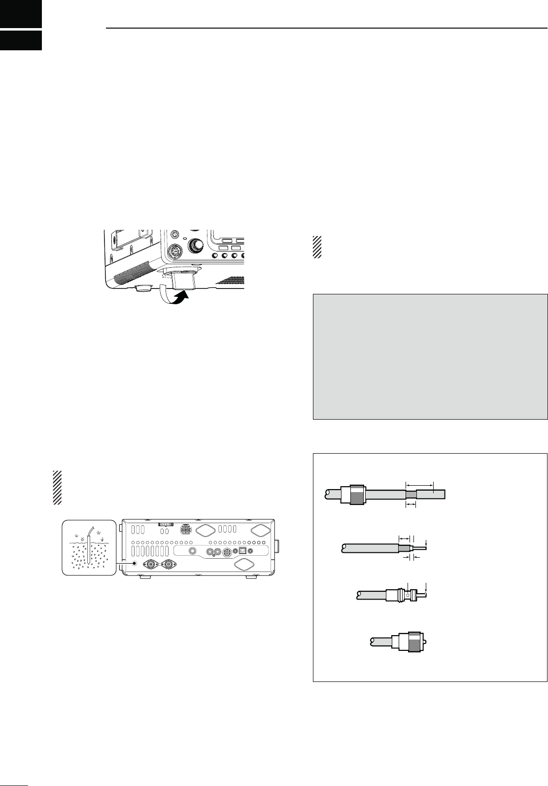
N3ELECTINGALOCATION
Select a location for the transceiver that allows ade-
quate air circulation, free from extreme heat, cold, or
vibrations, and away from TV sets, TV antenna ele-
ments, radios and other electromagnetic sources.
The base of the transceiver has adjustable feet for
desktop use. Set the feet to one of two angles, to meet
your operating preference.
N'ROUNDING
To prevent electrical shock, television interference
(TVI), broadcast interference (BCI) and other prob-
lems, ground the transceiver using the GROUND ter-
minal on the rear panel.
For best results, connect the heaviest possible gauge
wire or strap to a long ground rod. Make the distance
between the [GND] terminal and ground as short as
possible.
R 7!2.).'.%6%2 connect the [GND] ter-
minal to a gas or electric pipe, since the connection
could cause an explosion or electric shock.
[GND]
N!NTENNACONNECTION
For radio communications, the antenna is of criti-
cal importance, along with output power and receiver
sensitivity. Select a well-matched 50 ø antenna and
coaxial cable feedline. We recommend 1.5:1 or bet-
ter of Voltage Standing Wave Ratio (VSWR) on your
operating bands. The transmission line should be a
coaxial cable.
When using a single antenna, use the [ANT1] con-
nector.
#!54)/. Protect your transceiver from lightning
by using a lightning arrestor.
Antenna SWR
Each antenna is tuned for a specified frequency
range and the SWR usually increases outside the
range. When the SWR is higher than approx. 2.0:1,
the transceiver automatically reduces the TX power
to protect the final transistors. In that case, an
antenna tuner is useful to match the transceiver and
antenna. Low SWR allows full power for transmit-
ting. The IC-7410 has an SWR meter to continuously
monitor the antenna SWR.
PL-259 CONNECTOR INSTALLATION EXAMPLE
Slide the coupling ring
down. Strip the cable
jacket and tin the shield.
Slide the connector
body on and solder it.
Screw the coupling
ring onto the connec-
tor body.
Strip the cable as
shown at left. Tin the
center conductor.
q
w
e
r
30 mm
10 mm (tin here)
10 mm
1–2 mm
solder solder
tin
Coupling ring
30 mm (9⁄8 in) 10 mm (3⁄8 in) 1–2 mm (1⁄16 in)
16
2
INSTALLATION AND CONNECTIONS
1
2
3
4
5
6
7
8
9
10
11
12
13
14
15
16
17
18
19
20
21
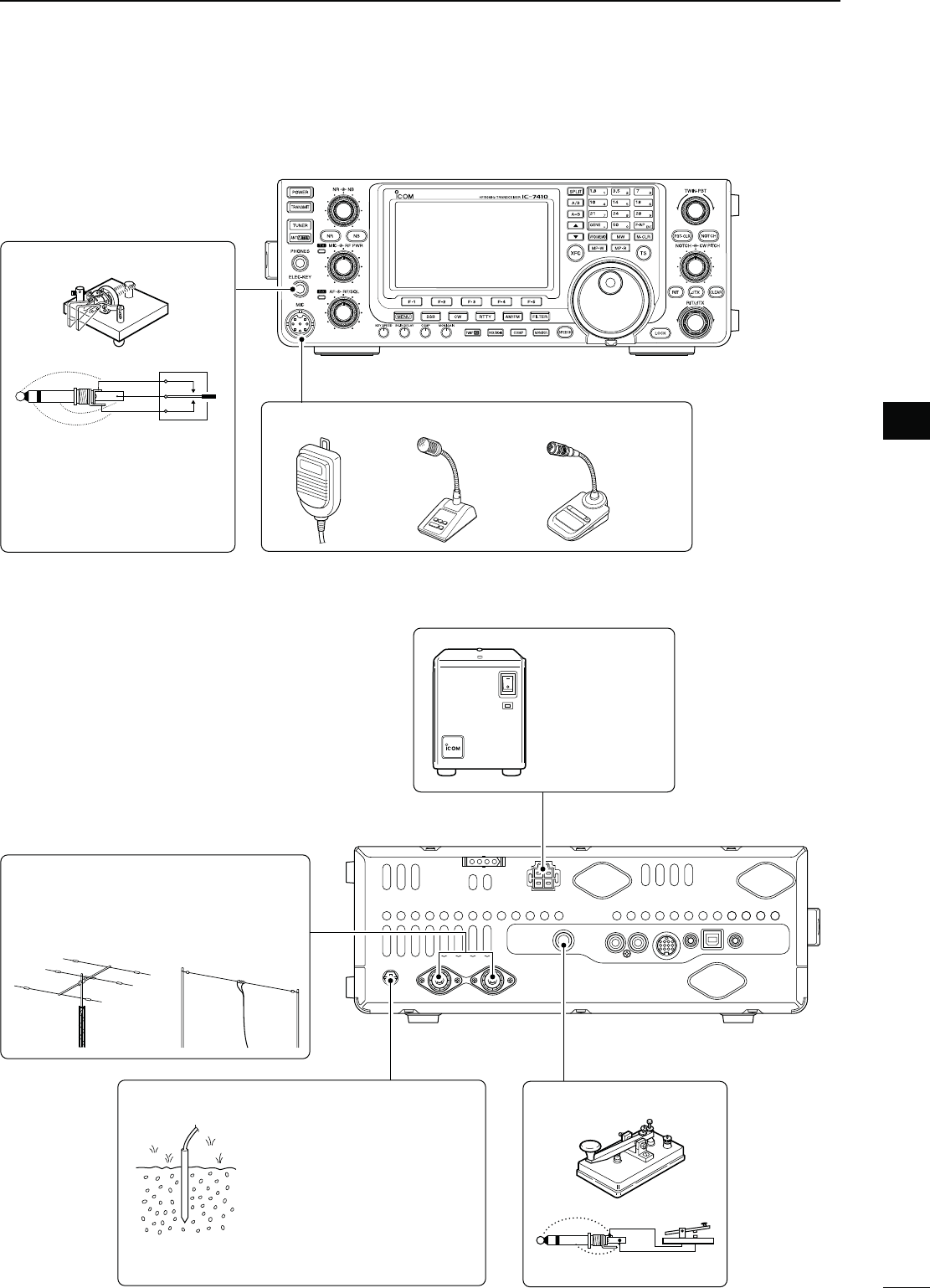
N2EQUIREDCONNECTIONS
D Front panel
+
_
DC POWER
SUPPLY
(p. 19)
PS-126
Use the heaviest possible
gauge wire or strap and
make the connection as
short as possible.
Grounding prevents elec-
trical shocks, TVI and
other problems.
GROUND (p. 15) STRAIGHT KEY
HF/50MHz ANTENNA 1, 2 (p. 15)
Connection example:
[ANT 1] for 1.8–18 MHz bands antenna
[ANT 2] for 21–28 MHz bands antenna
(dot)
(com)
(dash)
MICROPHONES (p. 22)
HM-36 SM-30
(option)
ELEC-KEY
A straight key cannot be
used when the “Keyer Type”
item is set to “ELEC-KEY” in
the Keyer Set mode. (p. 43)
D Rear panel
SM-50
(option)
17
2INSTALLATION AND CONNECTIONS
D Rear panel
N!DVANCEDCONNECTIONS
D Front panel
HEADPHONES
MIC
The AFSK modulation signal can also
be input to [MIC]. (p. 92)
AH-4 (option)
(p. 18)
AH-2b (option)
or long wire
with
ACC SOCKET
(p. 10)
REMOTE JACK, 53"#/..%#4/2 (p. 101)
Used for computer control and transceive operation.
The optional CT-17 is required when connecting a
PC to [REMOTE].
[ALC], [SEND] (p. 21)
Used for connecting a
non-Icom linear amplifier.
EXTERNAL SPEAKER
(p. 111)
SP-23
(option)
[ANT 1], [ANT 2] (p. 82)
Connect a linear amplifier,
antenna selector, etc.
18
2
INSTALLATION AND CONNECTIONS
1
2
3
4
5
6
7
8
9
10
11
12
13
14
15
16
17
18
19
20
21
N%XTERNALKEYPADCONNECTIONS
To pin e
To pin u
1.5 kø
±5%
1.5 kø
±5%
2.2 kø
±5%
4.7 kø
±5%
S1
(M1)
S2
(M2)
S3
(M3)
S4
(M4)
EXTERNAL KEYPAD
1
2
345
6
7
8
(Front view)
[MIC]
EXTERNAL KEYPAD
Connect an external keypad for direct
voice memory, keyer memory and
RTTY TX memory controls.
When using a external keypad, set
the “External Keypad” item to “KEYER
SEND” in the Set mode. (p. 88)
N%XTERNALANTENNATUNERCONNECTION
D#ONNECTINGTHE!(
The AH-4 must be connected to [ANT1].
Transceiver
Control cable
GND GND
[ANT1] AH-4
Long wire or optional AH-2b
[TUNER]
Coaxial cable (from the AH-4)
19
2INSTALLATION AND CONNECTIONS
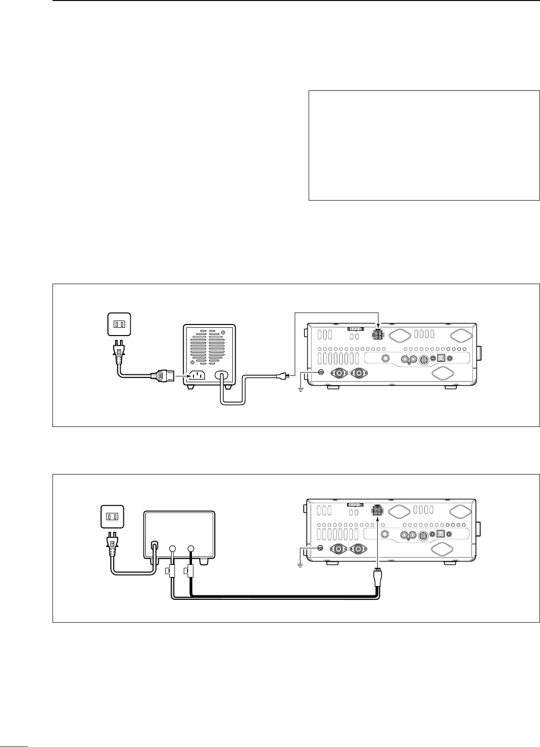
N0OWERSUPPLYCONNECTIONS
When operating the transceiver with AC power, use a
power supply with 13.8 V DC output and a capacity of
at least 23 Amps.
Refer to the diagrams below.
#!54)/. Before connecting the DC power
cable, check the following important items.
Make sure:
s4HE;0/7%2=SWITCHIS/&&
s/UTPUTVOLTAGEOFTHEPOWERSOURCEISn6
when you use a non-Icom power supply.
s$#POWERCABLEPOLARITYISCORRECT
Red : Positive + terminal
Black : Negative _ terminal
Transceiver
GND
PS-126
AC cable
AC outlet To [DC 13.8V]
+_
Supplied DC power cable
DC power cable
D#ONNECTINGTOTHE03$#0/7%23500,9
D#ONNECTINGTOANON)COM$#0/7%23500,9
AC cable
AC outlet
Transceiver
GND
A DC power supply
13.8 V;
at least 23 A
Red Black To [DC 13.8V]
N#ONNECTINGTOA$#POWERSUPPLY
20
2
INSTALLATION AND CONNECTIONS
1
2
3
4
5
6
7
8
9
10
11
12
13
14
15
16
17
18
19
20
21
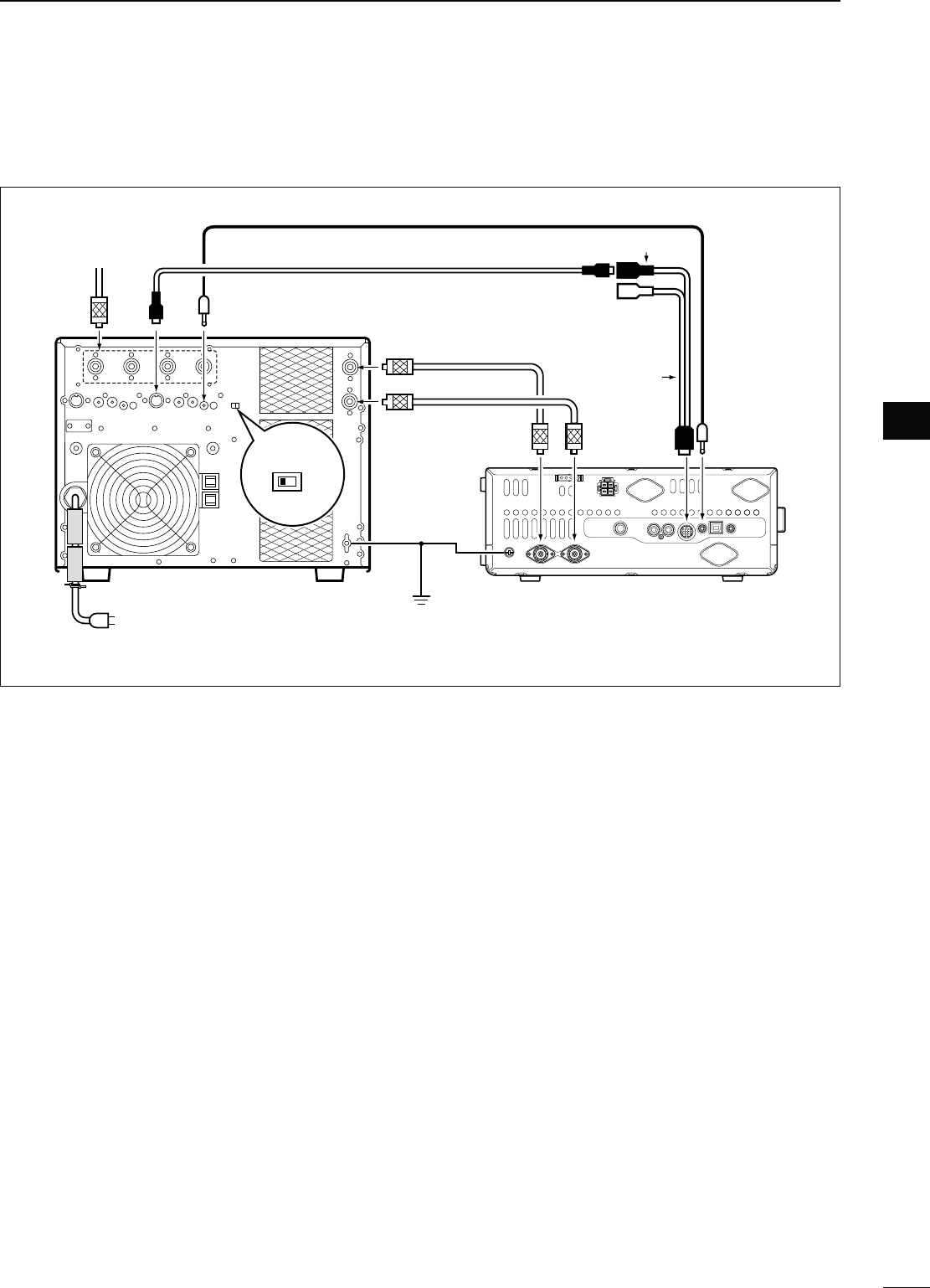
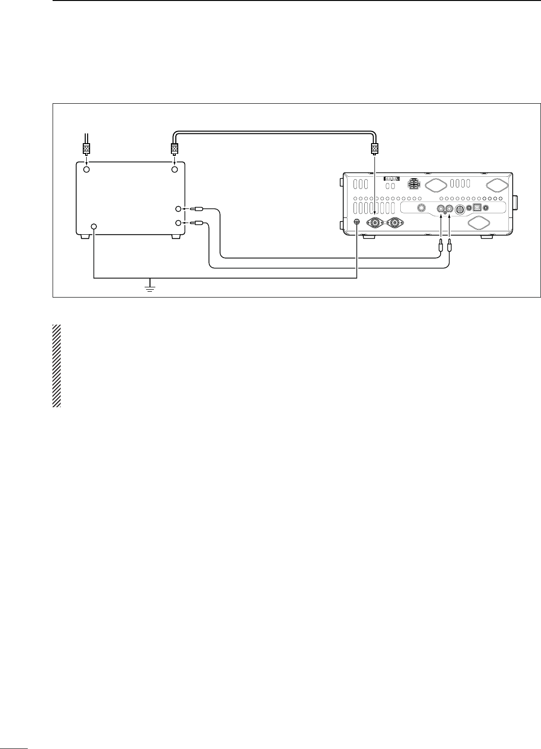
N,INEARAMPLIlERCONNECTIONS
D#ONNECTINGTHE)#0707%52/
EXCITER
11&2
Remote control cable (supplied with the IC-PW1/PW1EURO)
ACC cable (supplied with the IC-PW1/PW1EURO)
To an
antenna [ACC1]
[REMOTE][ANT]
IC-PW1/EURO
AC outlet
(Non-European versions : 100–120/200–240 V
European version : 230 V)
[INPUT1]
7-pin side
[REMOTE]
Coaxial cable
( supplied with the IC-PW1/
PW1EURO)
[ANT2]
Transceiver
[ACC]
GND
GND
[ANT1]
[INPUT2]
* If necessary, purchase sepa-
rately, and connect to [INPUT2].
GND
OPC-599
Coaxial cable*
21
2INSTALLATION AND CONNECTIONS
N Linear amplifier connections (Continued)
D#ONNECTINGANON)COMLINEARAMPLIlER
R7!2.).'
s3ETTHETRANSCEIVEROUTPUTPOWERANDLINEARAMPLIlER!,#OUTPUTLEVELAFTERREFERRINGTOTHELINEARAMPLIlERIN-
struction manual.
s4HE!,#INPUTLEVELMUSTBEINTHERANGE6TOn64HETRANSCEIVERDOESNOTACCEPTAPOSITIVEVOLTAGE.ON
matched ALC and RF power settings could overheat or damage the linear amplifier.
s4HE)#3%.$TERMINAL!##CONNECTORPINISRATEDAT6!$#)FTHISVALUEISEXCEEDEDALARGER
external relay must be used.
50 ø coaxial cable
To an antenna
Non-Icom linear
amplifier
RF OUTPUT
Transceiver
GND [ALC]
GND
GND
[ANT1]
ALC
SEND
[SEND]
RF INPUT
22
2
INSTALLATION AND CONNECTIONS
1
2
3
4
5
6
7
8
9
10
11
12
13
14
15
16
17
18
19
20
21
N-ICROPHONECONNECTORINFORMATION
(Front panel view)
y GND (PTT ground)
t PTT
r Squelch switch
q Microphone input
w +8 V DC output
e Frequency up/down
i AF output (varies with [AF])
GND
(Microphone ground)
u
[MIC]
Pin No. FUNCTION DESCRIPTION
w+8 V DC output Max. 10 mA
eFrequency up Ground
Frequency down Ground through 470 ˘
rSquelch open “Low” level
Squelch closed “High” level
#!54)/.$/./4 short pin 2 to ground as this
can damage the internal 8 V regulator. A DC volt-
age is applied to pin 1 for microphone operation.
Use caution when using a non-Icom microphone.
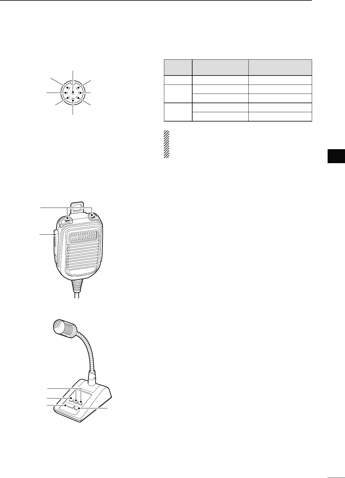
N-ICROPHONES
D HM-36
q
w
D SM-50 (option)
q
w
r
e
q UP/DOWN SWITCHES [UP]/[DN]
Push to change the frequency or memory channel.
s7HILEHOLDINGDOWNTHEFREQUENCYORMEMORYCHANNEL
number continuously increases or decreases.
s7HILEINTHESPLITFREQUENCYMODEANDHOLDINGDOWN
[XFC], push to change the transmit frequency.
s4HE;50=;$.=SWITCHCANBEUSEDASAKEYPADDLEIF
the “MIC Up/Down Keyer” item is set to “ON” in the
Keyer Set mode. In such case, the frequency and mem-
ory channel cannot be changed using the [UP]/[DN]
switches. (p. 43)
s9OUCANSETThe dot-dash polarity of the [UP]/[DN]
switch in the “Paddle Polarity” item in the Keyer Set
mode. When “Normal” is selected, [UP] sends a dash,
and [DN] sends a dot.
w PTT SWITCH
Hold down to transmit; release to receive.
e PTT LOCK SWITCH (available on only the SM-50)
Push to toggle between transmit and receive.
r LOW CUT SWITCH (available on only the SM-50)
Push to cut out the low frequency components of
input voice signals.
[RF/SQL]
: 12 o’clock
[MIC]
: 12 o’clock
[NR]
: Max. CCW
[CW PITCH]
: 12 o’clock
[RF PWR]
: Max. CW
[AF]
: Max. CCW
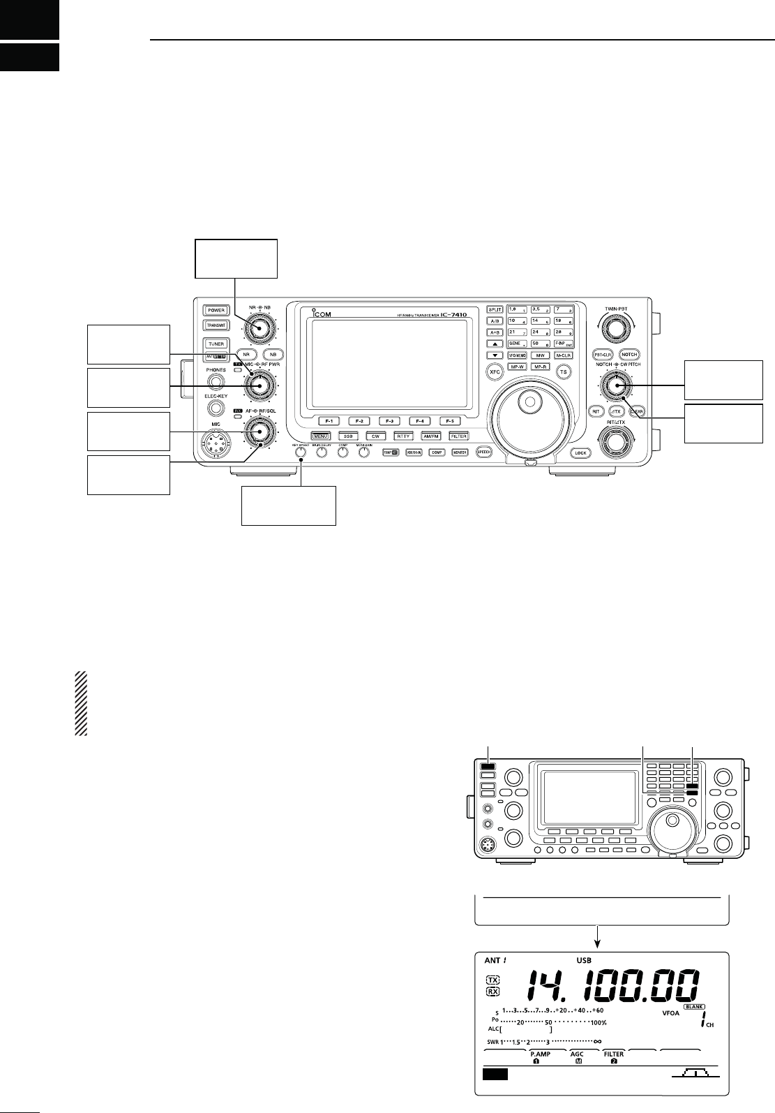
N"EFORElRSTAPPLYINGPOWER
Before turning ON your transceiver for the first time,
make sure all connections required for your system
are complete by reviewing them in Section 2 of this
manual.
After all connections have been made, set controls
and switches as shown in the illustration below.
3
23
"!3)#/0%2!4)/.
[POWER] [M-CLR] [F-INP ENT]
N4URNING/.#05RESETTING
First time to Power ON:
Reset the transceiver using the following procedure.
Resetting CLEARS all the programmed contents in
the memory channels, and returns all the pro-
grammed items in the Set mode to their default set-
tings.
q Make sure the transceiver’s power is OFF.
w
While holding down both [F-INP ENT] and [M-CLR],
push [POWER] to turn ON the transceiver.
s4HE#05ISRESET
s4HETRANSCEIVERDISPLAYSh!,,#,%!2vTHENDISPLAYES
its initial VFO frequency when resetting is complete.
e Change the Set mode settings to suit your operat-
ing needs. (p. 85)
Normal Power ON:
Push [POWER] to turn ON the transceiver.
Power OFF:
Hold down [POWER] for 1 second to turn OFF the
transceiver.
[NOTCH]
: 12 o’clock
CW : Clockwise
CCW : Counterclockwise
[KEY SPEED]
: 10–12 o’clock
ALL CLEAR
AGC TBW SCP
M1
24
3
BASIC OPERATION
1
2
3
4
5
6
7
8
9
10
11
12
13
14
15
16
17
18
19
20
21
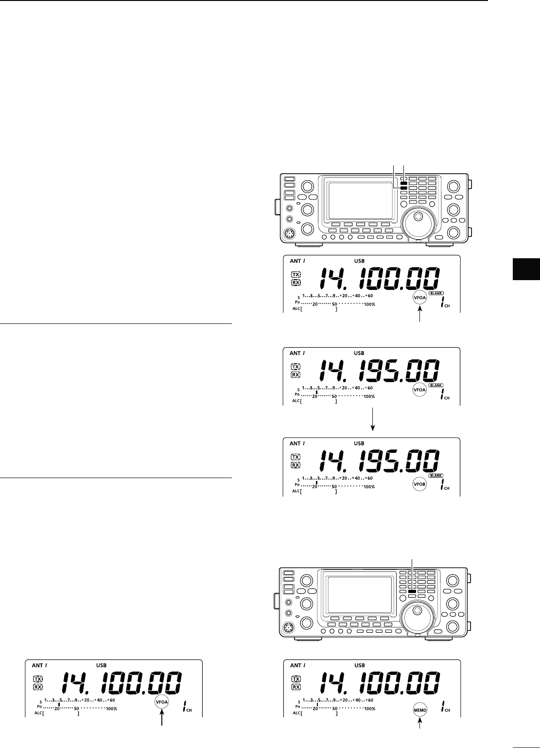
N6&/DESCRIPTION
The IC-7410 has two VFOs; “A” and “B,” that are con-
venient for quickly selecting two frequencies, or split
frequency operation. You can use either VFO to call up
a frequency and operating mode.
VFO is an abbreviation of Variable Frequency Oscil-
lator.
D 3ELECTINGTHE6&/!"
± Push [A/B] to switch between the VFO A and
VFO B.
sh6&/!vORh6&/"vAPPEARSWHENTHE6&/ISSELECTED
D 6&/EQUALIZATION
± Hold down [A=B] for 1 second to equalize the data
in both VFOs.
s4HREEBEEPSSOUNDWHENTHEEQUALIZATIONISCOMPLETE
CONVENIENT!
5SETWO6&/SASQUICKMEMORIES
When you find a new station, but wish to continue
searching, the dual VFO system can be used for quick
memory storage.
q Hold down [A=B] for 1 second to store the displayed
data into the undisplayed VFO.
w Continue searching for stations.
e Push [A/B] to show the stored data on the undis-
played VFO.
r To continue searching for stations, push [A/B] again
to show the displayed VFO.
N3ELECTING6&/-EMORYMODE
± Push [VFO/MEMO] to toggle between the VFO
and Memory modes.
sh6&/!v ORh6&/"v APPEARS WHEN IN THE 6&/ MODE
“MEMO” appears when in the Memory mode.
s(OLDING DOWN ;6&/-%-/= FOR SECOND COPIES THE
contents of the selected Memory channel into the dis-
played VFO. (p. 72)
The selected VFO icon The memory icon
[A/B] [A=B]
q Hold down [A=B]
e Push [A/B]
Displayed VFO
Undisplayed VFO
[VFO/MEMO]
The selected VFO icon
25
3BASIC OPERATION
D5SINGTHEBANDSTACKINGREGISTERS
q0USHABANDKEY;=TO;=OR;'%.%s=
s4HEPREVIOUSLYSELECTEDFREQUENCYANDOPERATINGMODE
are called up as the first band stacking register of that
frequency band.
w Select a frequency and an operating mode, and
then push the band key.
s4HESELECTEDFREQUENCYANDMODEAREMEMORIZEDAS
that frequency band’s first band stacking register.
e Select another frequency and operating mode, and
then push the band key.
s4HESELECTEDFREQUENCYANDMODEAREMEMORIZEDAS
that frequency band’s second band stacking register.
r Select another frequency and operating mode, and
then push the band key.
s4HESELECTEDFREQUENCYANDMODEAREMEMORIZEDAS
that frequency band’s third band stacking register.
t The first band stacking register set in step w, is
called up.
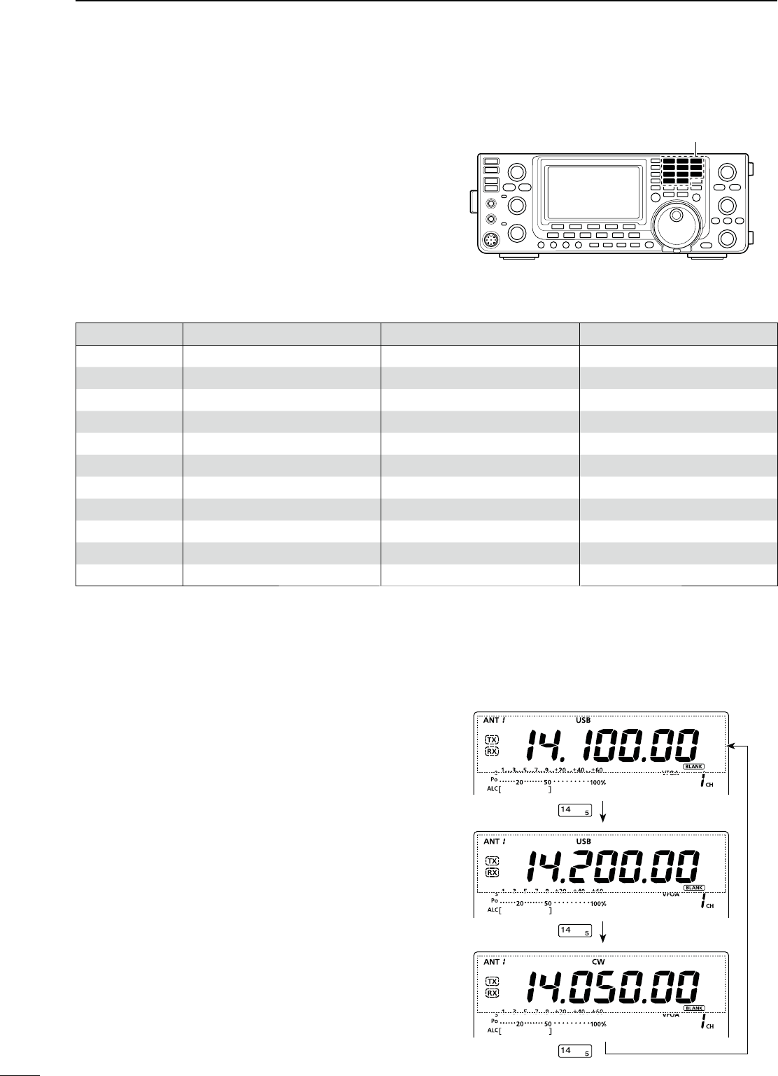
s7HENTHEFREQUENCYBANDKEYISPUSHEDTHEMEMO-
rized triple band stacking registers are sequentially
called up.
N3ELECTINGAFREQUENCYBAND
The triple band stacking register provides three mem-
ories for each band key to store frequencies and
operating modes.
This function is convenient when you operate three op-
erating modes on one frequency band. For example,
one register can be used for a CW frequency, another
for an SSB
frequency and the other one for an RTTY
frequency.
See the table below for a list of the bands available
and the default settings for each band.
Band keys
"!.$ REGISTER 1 REGISTER 2 REGISTER 3
1.8 MHz 1.900000 MHz CW 1.910000 MHz CW 1.915000 MHz CW
3.5 MHz 3.550000 MHz LSB 3.560000 MHz LSB 3.580000 MHz LSB
7 MHz 7.050000 MHz LSB 7.060000 MHz LSB 7.020000 MHz CW
10 MHz 10.120000 MHz CW 10.130000 MHz CW 10.140000 MHz CW
14 MHz 14.100000 MHz USB 14.200000 MHz USB 14.050000 MHz CW
18 MHz 18.100000 MHz USB 18.130000 MHz USB 18.150000 MHz USB
21 MHz 21.200000 MHz USB 21.300000 MHz USB 21.050000 MHz CW
24 MHz 24.950000 MHz USB 24.980000 MHz USB 24.900000 MHz CW
28 MHz 28.500000 MHz USB 29.500000 MHz USB 28.100000 MHz CW
50 MHz 50.100000 MHz USB 50.200000 MHz USB 51.000000 MHz FM
General*1 15.000000 MHz USB 15.100000 MHz USB 15.200000 MHz USB
*1 ;'%.s=SELECTSTHEGENERALCOVERAGEBAND
Push
Push
Push
;%XAMPLE= 14 MHz frequency band
26
3
BASIC OPERATION
1
2
3
4
5
6
7
8
9
10
11
12
13
14
15
16
17
18
19
20
21
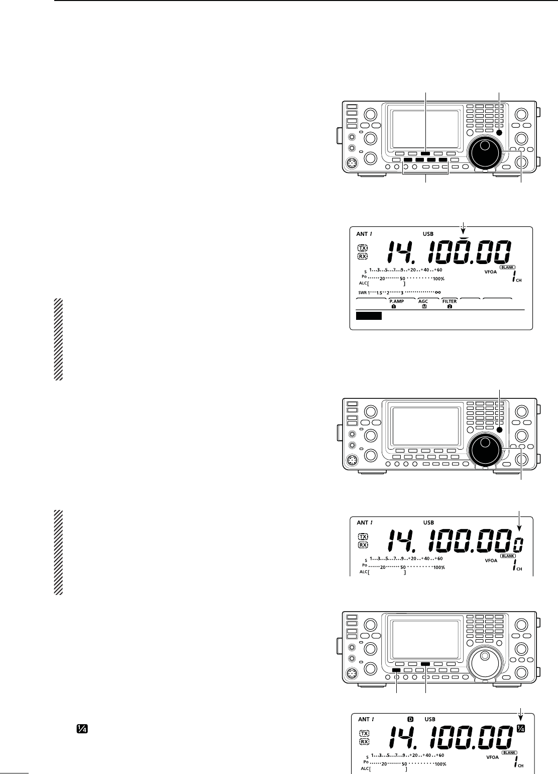
N&REQUENCYSETTING
You can select the transceiver’s frequency by using
[DIAL], or you can enter it using the keypad.
D4UNINGWITH;$)!,=
q Select the desired frequency band.
s0USHABANDKEYnTIMES4HREEDIFFERENTFREQUENCIES
on each frequency band can be selected with the band
key. (See the previous page “Using the band stacking
registers.”)
s4HEDEFAULTTUNINGSTEPDIFFERSDEPENDINGONTHEOPER-
ating mode.
SSB/CW/RTTY : 10 Hz
AM : 1 kHz (“Z” is displayed)
FM : 10 kHz (“Z” is displayed)
w Rotate [DIAL] to set the desired frequency.
If the Dial Lock function is ON, “ ” is displayed,
and [DIAL] does not function.
In this case, push [LOCK] to turn OFF the Dial Lock
function. (p. 61)
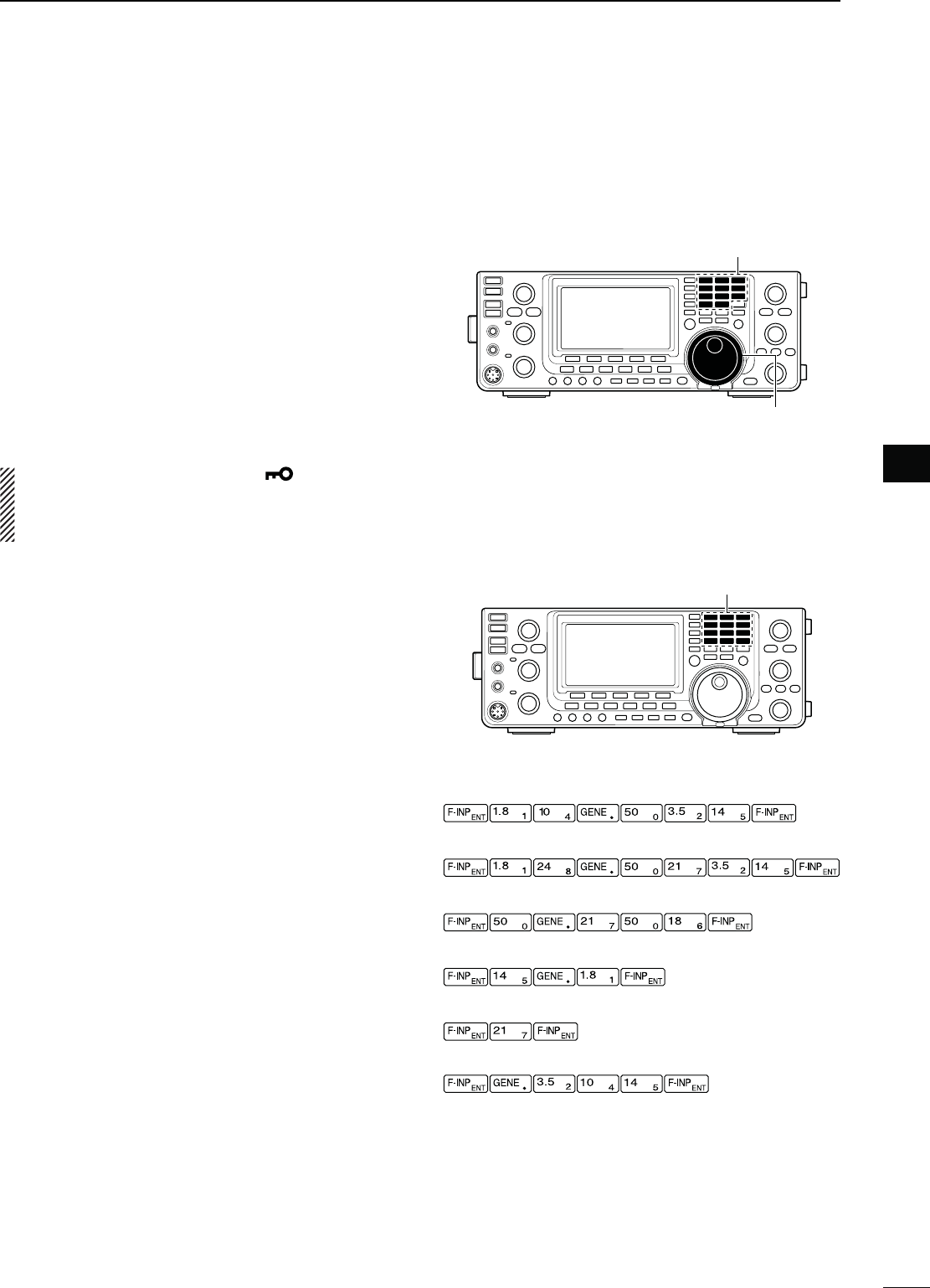
D$IRECTFREQUENCYENTRYWITHTHEKEYPAD
The transceiver has a keypad for direct frequency
entry, as described below.
q Push [F-INP ENT] to enter frequencies with the
keypad.
s!LLFREQUENCYDIGITSDISAPPEAR
w Push the numeric keys to input the desired fre-
quency.
s0USH;'%.%s=TOINPUTAhvDECIMALPOINTBETWEENTHE
MHz digits and kHz digits.
e Push [F-INP ENT] to set the input frequency.
s4OCANCELTHEINPUTPUSHANYKEYSUCHAS;-7=OR
[M-CLR], before pushing [F-INP ENT].
Keypad
[EXAMPLE]
14.025 MHz
18.0725 MHz
K(Z
5.100 MHz
7.000 MHz
21.280 MHz ¶ 21.245 MHz
Band keys
[DIAL]
27
3BASIC OPERATION
N Frequency setting (continued)
D1UICK4UNINGFUNCTION
The operating frequency can be changed in “kHz”
steps for quick tuning. You can set a tuning step in
each operating mode.
q Push [TS] to turn ON the Quick Tuning function.
shZ” appears above the 1 kHz digit.
w Hold down [TS] for 1 second to display the “TS”
screen (Tuning Step).
e Select a desired operating mode.
r Rotate [DIAL] to select a tuning step.
sANDK(ZARESELECTABLE
s(OLDDOWN;&=FORSECONDTORESETTOTHEDEFAULTSET-
ting, if desired.
t Repeat steps e and r to select quick tuning steps
for other modes.
y Push [TS] to exit the “TS” screen.
./4%
s4OTURN/&&THE1UICK4UNINGFUNCTIONPUSH;43=
again.
s7HENTHE1UICK4UNINGFUNCTIONIS/&&THEFRE-
quency will be changed in 10 Hz steps.
s4ODISPLAYTHEh43vSCREENTHE1UICK4UNINGFUNC-
tion must be turned ON first.
D3ELECTING(ZSTEP
You can change the frequency in 1 Hz steps for fine
tuning.
q If the Quick Tuning function is ON, push [TS] to
turn OFF.
w Hold down [TS] for 1 second to turn the 1 Hz tuning
step ON or OFF.
./4%
s7HEN2)4ANDOR∂TX are used, they also tune in
1 Hz tuning steps.
s4HEFREQUENCYCHANGESIN(ZSTEPSWHENTHE
[UP]/[DN] switches of the microphone are used
for frequency tuning (if the Quick Tuning function
is OFF.)
D 1⁄44UNING3TEPFUNCTION
-ODE33"$#72449
The dial speed is reduced to 1⁄4 of the normal speed
when the 1⁄4 Tuning Step function is ON, for finer tun-
ing control.
q Push [MENU] to display the “M1” screen (Menu 1).
w Push [1⁄4](F-3) to turn the 1⁄4 Tuning Step function
ON or OFF.
sh ” appears when the 1⁄4 Tuning Step function is ON.
1kHz
SSB
TS
Appears
[TS][F-3]
Mode selection [DIAL]
[TS]
[DIAL]
[MENU] [1⁄4] Appears
Appears
28
3
BASIC OPERATION
1
2
3
4
5
6
7
8
9
10
11
12
13
14
15
16
17
18
19
20
21
D!UTO4UNING3TEPFUNCTION
When you rotate [DIAL] rapidly, the tuning speed can
automatically accelerate, depending on the “MAIN
DIAL Auto TS” setting in the Set mode.
q Hold down [MENU] for 1 second to enter the Set
mode.
w Push [Y](F-1) or [Z](F-2) to select “MAIN DIAL
Auto TS.”
e Rotate [DIAL] to select the HIGH or LOW tuning
speed acceleration, or to turn OFF the function.
s()'(7HENTHETUNINGSTEPISSETTOK(ZOR
smaller steps, the tuning speed is approxi-
mately five times faster.
When the tuning step is set to 5 kHz or
larger steps, the tuning speed is approxi-
mately two times faster. (default)
s,/7!PPROXIMATELYTWOTIMESFASTER
s/&& 4URNSTHEFUNCTION/&&
s(OLDDOWN;&=FORSECONDTORESETTOTHEDEFAULTSET-
ting, if desired.
r Push [MENU] to save, and exit the Set mode.
Operation on the 5 MHz frequency band is allowed on
5 discrete frequencies and must adhere to the follow-
ing:
s4HE53"53"$ATAAND#7MODES
s
Maximum of 100 watts ERP (Effective Radiated Power)
sK(ZBANDWIDTHMAXIMUM
It is your responsibility to set all controls so that trans-
mission in this frequency band meets the stringent
conditions under which amateur operations may use
these frequencies.
./4% We recommend that you store these fre-
quencies, modes and filter settings into memory
channels, for easy recall.
[][]
[DIAL][MENU]
HIGH (default)
Ù26 ÚHIGH
SET MAIN DIAL Auto TS
s&ORTHE53"AND53"$ATAMODES
The FCC specifies center frequencies on the 5 MHz fre-
quency band. However, the transceiver displays carrier
frequency. Therefore, tune the transceiver to 1.5 kHz
below the specified FCC channel center frequency.
4RANSCEIVER$ISPLAYED
&REQUENCY
&###HANNEL
#ENTER&REQUENCY
5.33050 MHz 5.33200 MHz
5.34650 MHz 5.34800 MHz
5.35700 MHz 5.35850 MHz
5.37150 MHz 5.37300 MHz
5.40350 MHz 5.40500 MHz
s&ORTHE#7MODE
The transceiver displays the center frequency. There-
fore, tune the transceiver to the specified FCC channel
frequency when you operate in these modes.
4RANSCEIVER$ISPLAYED
&REQUENCY
&###HANNEL
#ENTER&REQUENCY
5.33200 MHz 5.33200 MHz
5.34800 MHz 5.34800 MHz
5.35850 MHz 5.35850 MHz
5.37300 MHz 5.37300 MHz
5.40500 MHz 5.40500 MHz
D!BOUTTHE-(ZFREQUENCYBANDOPERATION53!VERSIONONLY
To assist you in operating within the rules specified
by the FCC, transmission is illegal on any frequen-
cies other than the five shown in the tables below.
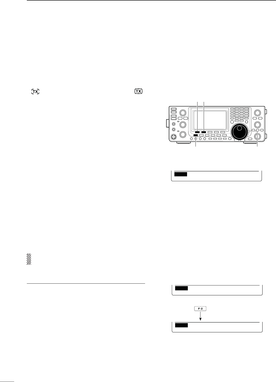
29
3BASIC OPERATION
N Frequency setting (continued)
D"ANDEDGEWARNINGBEEP
You can hear a beep tone when you tune in or out of
an amateur band’s frequency range. A regular beep
sounds when you tune into a range, and an lower tone
error beep sounds when you tune out of a range.
Also, the TX icon appears if the selected frequency is
in or out of an amateur band, when an option other
than “OFF” is selected.
sh ” is displayed, instead of the regular TX icon “ ,”
while the operating frequency is out of an amateur band.
q Hold down [MENU] for 1 second to enter the Set
mode.
w Push [Y](F-1) or [Z](F-2) to select “Band Edge
Beep.”
e Rotate [DIAL] to select the desired band edge warn-
ing beep setting.
s/&& "ANDEDGEBEEPIS/&&
s/.$EFAULT 7HEN YOU TUNE INTO OR OUT OF
the default amateur band’s fre-
quency range, a beep sounds.
(default)
s/.5SER 7HEN YOU TUNE INTO OR OUT OF
a user programmed amateur
band’s frequency range, a beep
sounds.
s/.5SER487HEN YOU TUNE INTO OR OUT OF
a user programmed amateur
band’s frequency range, a beep
sounds. Also transmission is in-
hibited outside the programmed
range.
s(OLDDOWN;F-3] for 1 second to reset to the default set-
ting, if desired.
r Push [MENU] to save, and exit the Set mode.
The beep output level can be set in the “Beep Level”
item of the Set mode. (p. 85)
!BOUTTHEUSERBANDEDGEFREQUENCIES
7HENh/.5SERvORh/.5SER48vISSELECTEDIN
the “Band Edge Beep” item, a total of 30 band edge
frequencies can be programmed in the “User Band
Edge” item. See the next page for details.
If “OFF” or “ON (Default)” is selected, the “User Band
Edge” item does not appear in the Set mode.
[][]
[DIAL][MENU]
ON (Default)
Ù 6 ÚON(Default)
SET Band Edge Beep
ON (User) selection
Ù 6 ÚON(User)
SET Band Edge Beep
[User Band Edge] item
Ù 7 ÚDEF EDT
SET User Band Edge
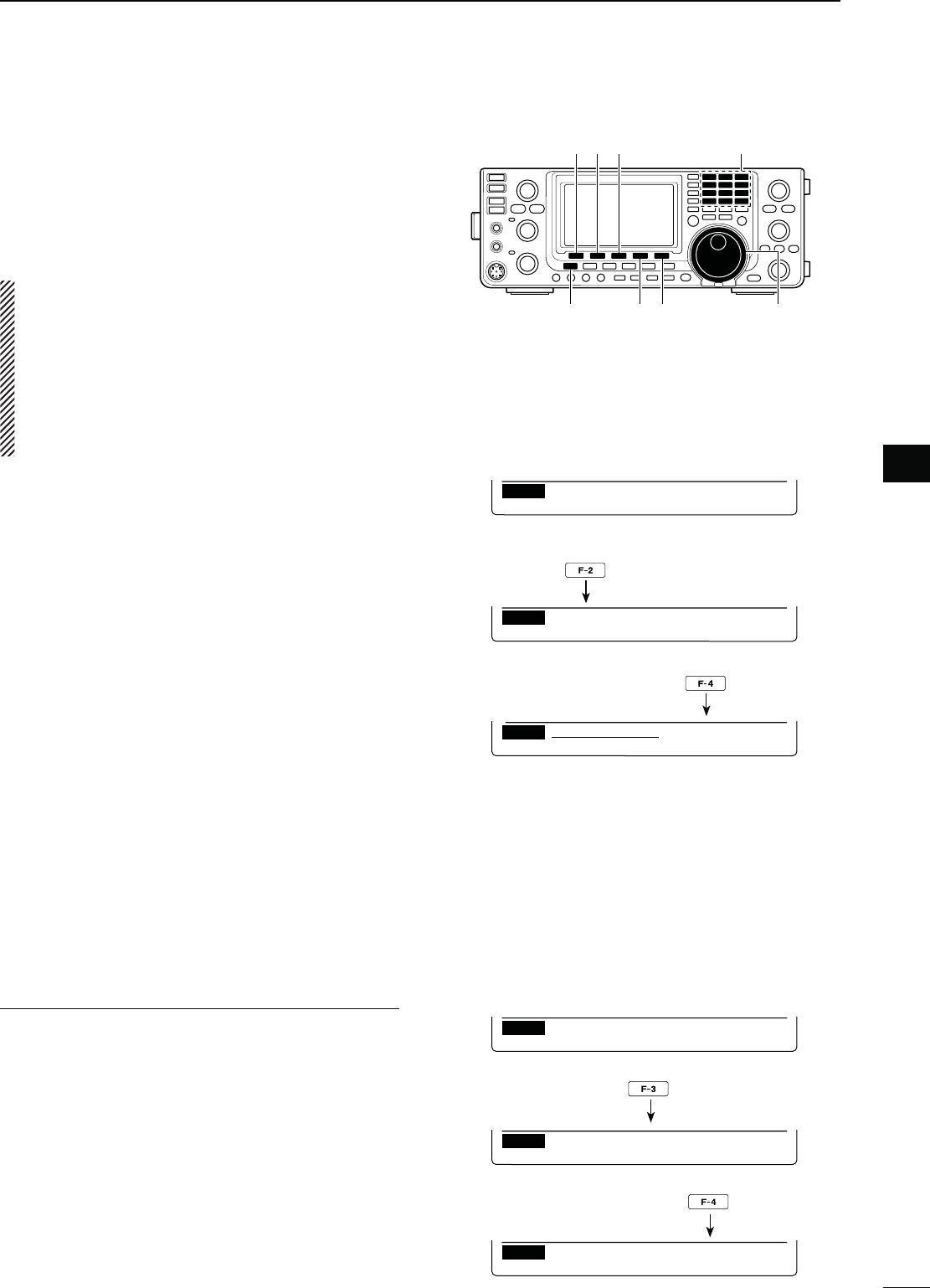
30
3
BASIC OPERATION
1
2
3
4
5
6
7
8
9
10
11
12
13
14
15
16
17
18
19
20
21
D0ROGRAMMINGTHEUSERBANDEDGE
7HENh/.5SERvORh/.5SER48,IMITvISSE-
lected in the “Band Edge Beep” item, the “User Band
Edge” item appears in the Set mode.
A total of 30 band edge frequencies can be pro-
grammed in the “User Band Edge” item.
./4%
s!LLFREQUENCYRANGESARESETTODEFAULTSO YOU
should delete or change them to add the desired
band edge frequency.
s0ROGRAMEACHCHANNELFROMLEFTTORIGHTANDEACH
frequency must be higher than the preceding fre-
quency.
s4HEFREQUENCYTHATISDUPLICATEDOROUTOFANAMA-
teur band, cannot be programmed.
q Hold down [MENU] for 1 second to enter the Set
mode.
w Push [Y](F-1) or [Z](F-2) to select “Band Edge
Beep.”
e Rotate [DIAL] to select either “ON (User)” or “ON
5SER48v
r Push [Z](F-2) to select “User Band Edge.”
t Push [EDT](F-4) to display the “EDG” screen (Band
Edge Program).
y Push [Y](F-1) or [Z](F-2) to select the desired band
edge.
s(OLDINGDOWN;Y](F-1) or [Z](F-2) continuously selects
the band edges.
s0USH;Ω ≈](F-3) to select the upper or lower band edge
frequency entry status.
s(OLDDOWN;$%,=&FORSECONDTODELETETHESE-
lected band edge.
s0USH;).3=&TOINSERTANEWBLANKBANDEDGE
u Input the desired frequency with the keypad, then
push [F-INP ENT].
s0USH;'%.%s=to input decimal point (“.”) between the
MHz and kHz digits.
i Push [MENU] to save.
o Push [MENU] again to exit the Set mode.
4ORESETTHEBANDEDGEFREQUENCIES
If you want to reset the band edge frequencies to their
default (initial) settings, select the “User Band Edge”
item, then hold down [DEF](F-3) for 1 second.
The band edge initialize screen appears, then hold
down [YES](F-4) for 1 second to reset all band edge
frequency settings to their default settings.
ON (User) setting in the
“Band Edge Beep” item
Ù 6 ÚON(User)
SET Band Edge Beep
“User Band Edge” item
Ù 7 ÚDEF EDT
SET User Band Edge
“EDG” screen
1
INS DEL
EDG
1.600.000- 29.999.999
“User Band Edge” item
Ù 7 ÚDEF EDT
SET User Band Edge
Band edge initialize screen
NOYES
SET Initialize Edges?
Ù 7 ÚDEF EDT
SET User Band Edge
Hold down
Hold down
[][][]
[] [DEL] [DIAL][MENU]
Keypad
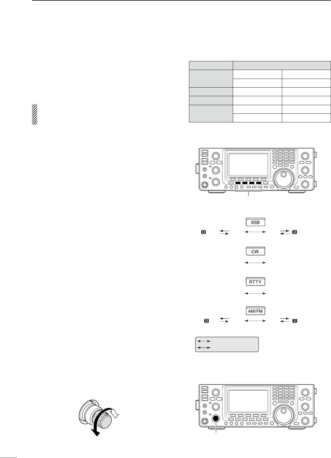
N/PERATINGMODESELECTION
The usable operating modes in the IC-7410 are listed
to the right.
You can select the desired operating mode by push-
ing the appropriate mode switch.
See the diagram to the right for the order of selection.
When the data mode is selected, you can mute the
microphone signals, depending on the “DATA MOD”
setting in the Set mode (p. 89).
s3ELECTINGTHE33"MODE
± Push [SSB] to alternately select the USB or LSB
mode.
sWhen operating above 10 MHz, USB is selected first;
when operating below 10 MHz, LSB is selected first.
s!FTER53" OR ,3" IS SELECTED HOLD DOWN;33"=FOR
1 second to select the data mode.
s)NTHEDATAMODEPUSH;33"=TORETURNTOTHENORMAL
SSB mode.
s3ELECTINGTHE#7MODE
± Push [CW] to alternately select the CW or CW-R
(CW reverse) mode.
s3ELECTINGTHE2449MODE
± Push [RTTY] to alternately select the RTTY or
RTTY-R (RTTY reverse) mode.
s3ELECTINGTHE!-&-MODE
± Push [AM/FM] to alternately select the AM or FM
mode.
s!FTER!-OR&- IS SELECTED HOLDDOWN;!-&-=FOR
1 second to select the data mode.
s)NTHEDATAMODEPUSH;!-&-=TORETURNTOthe normal
AM or FM mode.
N6OLUMESETTING
± Rotate the [AF] control clockwise to increase the
audio output level, counterclockwise to decrease it.
Increases
Decreases
31
3BASIC OPERATION
Mode switches
CW CW-R
RTTY RTTY-R
USBUSB LSB LSB
AMAM FM FM
: Push momentary
: Hold down for 1 second
s5SABLEOPERATINGMODES
-ODESWITCH /PERATINGMODE
;33"= USB USB Data
LSB LSB Data
[CW] CW CW Reverse
[RTTY] RTTY RTTY Reverse
[AM/FM] AM AM Data
FM FM Data
[AF]
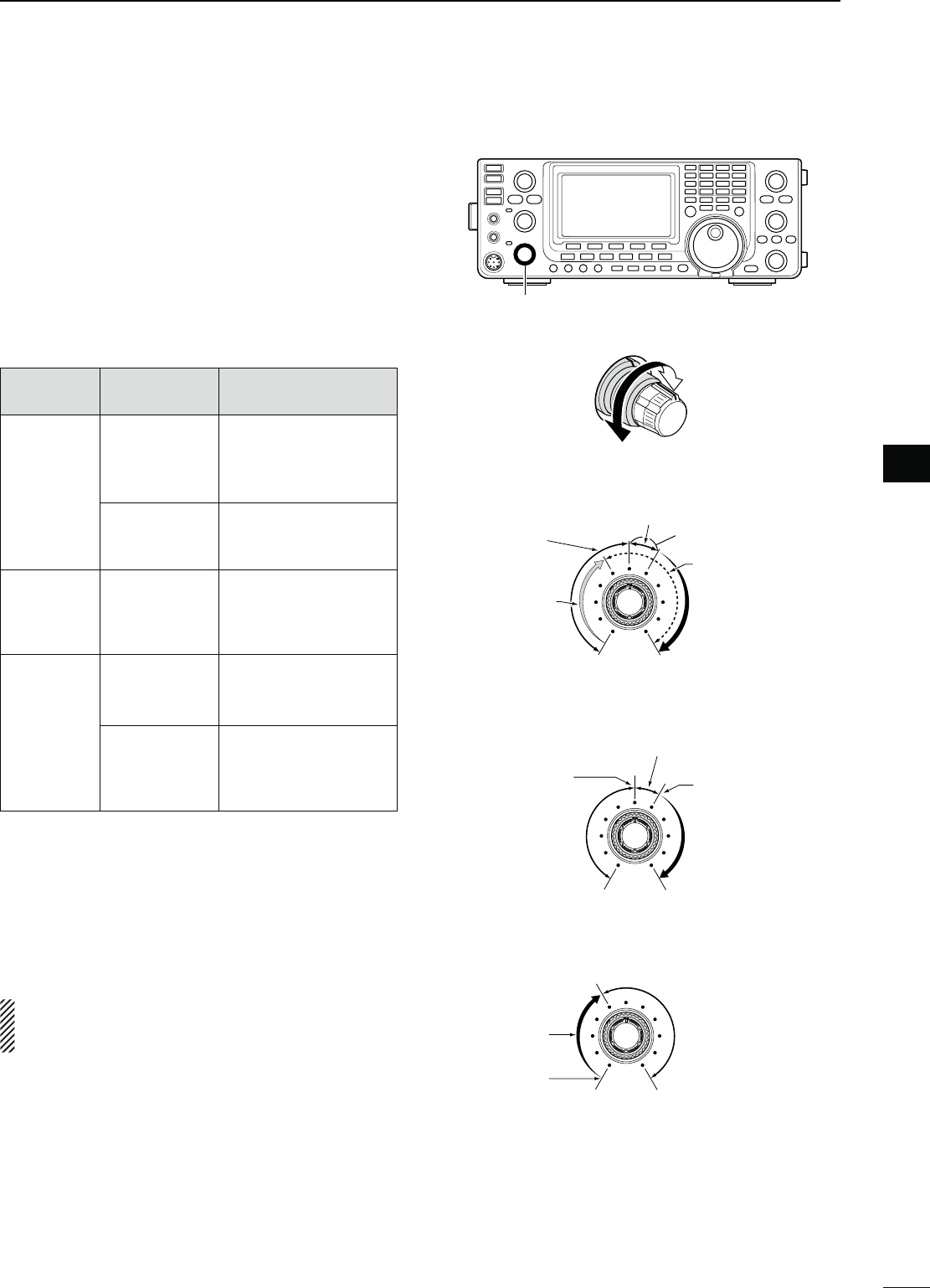
32
3
BASIC OPERATION
1
2
3
4
5
6
7
8
9
10
11
12
13
14
15
16
17
18
19
20
21
N3QUELCHANDRECEIVE2&SENSITIVITY
Adjusts the RF gain and squelch threshold level. The
squelch removes noise output to the speaker when no
signal is received (closed position).
s4HESQUELCHISPARTICULARLYEFFECTIVEFOR!-AND&-BUTCAN
also be used in other modes.
s4HETOOCLOCKPOSITIONISRECOMMENDEDFORTHEMOST
effective use of the [RF/SQL] control.
s;2&31,=CANOPERATEASONLYAN2&GAINCONTROLSquelch
is fixed open) or only a squelch control (RF gain is fixed at
maximum sensitivity), depending on the “RF/SQL Control”
setting in the Set mode. (p. 86)
SET MODE
SETTING
OPERATING
MODE
[RF/SQL]
OPERATION
RF+SQL
(default)
FM
Operates as an RF
gain control, and a
noise squelch or S-
meter squelch.
SSB/CW/
RTTY/AM
Operates as an RF
gain control, and an S-
meter squelch.
SQL ALL
Operates as only a
squelch control.
s2&GAINISlXEDATMAXI-
mum sensitivity.
AUTO
SSB/CW/
RTTY
Operates as only an
RF gain control.
s3QUELCHISlXEDOPEN
AM/FM
Operates as only a
squelch control.
s2&GAINISlXEDATMAXI-
mum sensitivity.
M!DJUSTING2&GAIN(Receive sensitivity)
Normally, [RF/SQL] is set to the 12 o’clock position.
Rotate [RF/SQL] to the 11 o’clock position for maxi-
mum sensitivity.
s2OTATINGCOUNTERCLOCKWISEFROMTHEMAXIMUMPOSITIONRE-
duces sensitivity.
s4HE3METERINDICATESRECEIVESENSITIVITY
While rotating the RF gain control, noise may be
heard. This comes from the DSP unit and does not
indicate an equipment malfunction.
M!DJUSTINGSQUELCH(Removing non-signal noise)
Rotate [RF/SQL] clockwise when no signal is received,
until the noise just disappears.
s4HE28INDICATORLIGHTGOESOUT
s2OTATING;2&31,=PASTTHETHRESHOLDPOINTACTIVATESTHE
S-meter squelch— this allows you to set a minimum signal
level needed to open the squelch.
[RF/SQL]
s7HENFUNCTIONINGASAN2&GAINSQUELCHCONTROL
Maximum
RF gain
S-meter
squelch
Noise squelch (FM mode)
Squelch is
open.
RF gain
adjustable
range
Recommended level
s7HENFUNCTIONINGASASQUELCHCONTROL
(RF gain is fixed at maximum.)
Squelch is
open.
S-meter
squelch
S-meter squelch
threshold
Noise squelch
threshold
(FM mode)
Shallow Deep
Noise squelch (FM mode)
s7HENFUNCTIONINGASAN2&GAINCONTROL
(Squelch is fixed open; SSB, CW, RTTY only)
Minimum RF gain
Adjustable
range
Maximum
RF gain
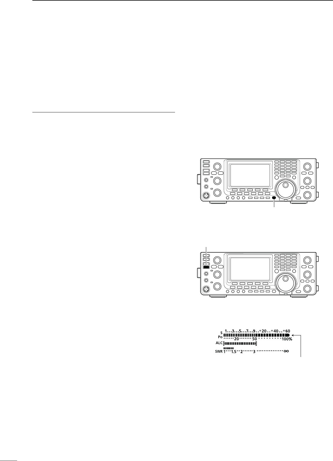
33
3BASIC OPERATION
N6OICESYNTHESIZEROPERATION
The IC-7410 has a built-in voice synthesizer to an-
nounce the operating frequency, mode and S-meter
level in clear, electronically-generated voice, in Eng-
lish (or Japanese).
First, select the desired parameters to be announced
in the Set mode. (p. 87)
)NITIALVALUESFORTHEVOICESYNTHESIZERPARAMETERS
s30%%#(,EVEL
s30%%#(,ANGUAGE %NGLISH
s30%%#(3PEED ()'(
s30%%#(3,EVEL /.
s30%%#(;-/$%=37/&&
± Push [SPEECH] to announce the S-meter level*
and currently selected frequency.
s)FYOUHOLDDOWN;30%%#(=FORSECONDTHETRANS-
ceiver announces the operating mode after the fre-
quency.
* The S-meter level announcement can be turned OFF.
(p. 87)
± Push a mode switch to announce the appropriate
mode, when the “SPEECH [MODE] SW” item is set
to “ON” in the Set mode. (p. 87)
N-ETER$ISPLAYSELECTION
The transceiver has four transmit meter functions for
your convenience. In addition to Po and ALC, you can
display the SWR or COMP meter by holding down
;!.4s-%4%2=FORSECOND
s0O $ISPLAYSTHE2&OUTPUTPOWERINPERCENT
s!,# $ISPLAYSTHE!,#LEVEL7HENTHEMETERMOVE-
ment shows the input signal level exceeds the
allowable level, the ALC limits the RF power.
In such cases, rotate the [MIC] control counter-
clockwise to decrease the microphone gain.
s372 $ISPLAYSTHE372OFTHEANTENNAATTHEFRE-
quency.
s#/-0$ISPLAYS THE COMPRESSION LEVEL WHEN THE
speech compressor is in use.
[SPEECH]
]
s7HENTHE372METERISSELECTED
The RF output power
meter becomes the
S-meter in receive.
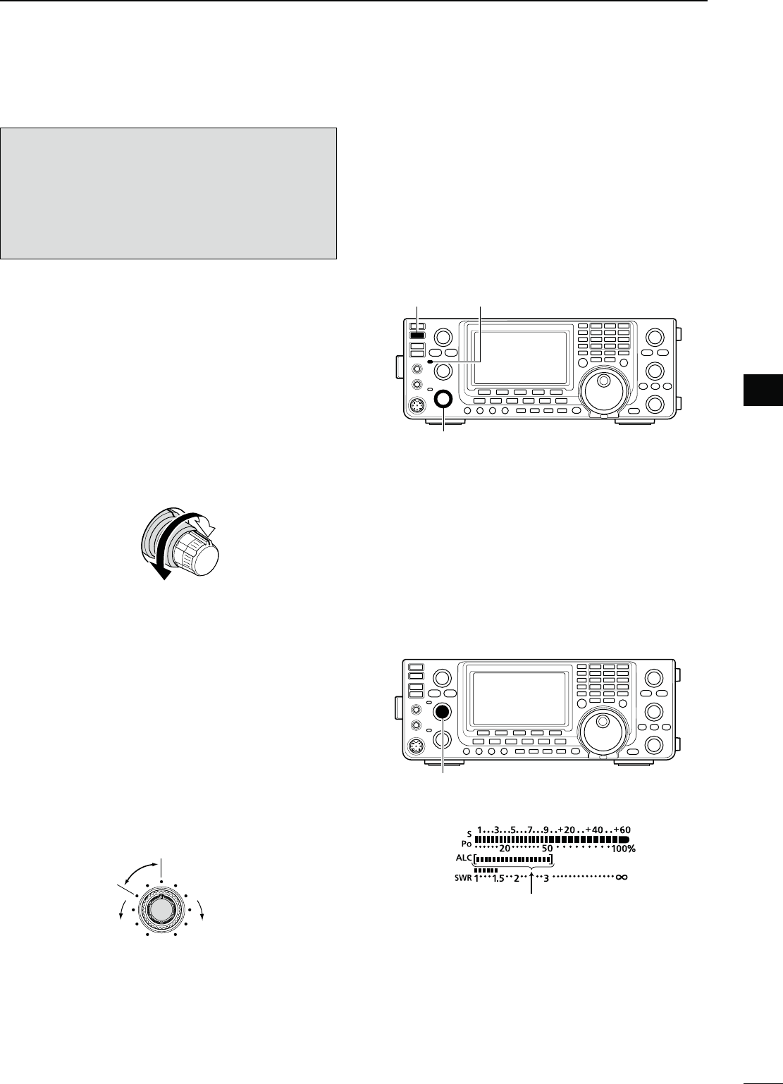
34
3
BASIC OPERATION
1
2
3
4
5
6
7
8
9
10
11
12
13
14
15
16
17
18
19
20
21
N"ASICTRANSMITOPERATION
"EFORE TRANSMITTING MONITOR THE OPERATING FRE-
QUENCY TO MAKE SURE TRANSMITTING WONT CAUSE
INTERFERENCE TO OTHER STATIONS ON THE SAME FRE-
QUENCY )TS GOOD AMATEUR PRACTICE TO LISTEN
lRSTANDTHENEVENIFNOTHINGISHEARDASKh)S
THE FREQUENCY IN USEv ONCE OR TWICE BEFORE
YOUBEGINOPERATINGONTHATFREQUENCY
D4RANSMITTING
q Push [PTT] on the microphone to transmit (or
[TRANSMIT] on the transceiver).
s4HE48INDICATORLIGHTSRED
w Release [PTT] to receive (or push [TRANSMIT]
again).
Adjusting the transmit output power
± Rotate [RF PWR].
s!DJUSTABLERANGE7TO7
(2 W to 27 W in the AM mode)
Increases
Decreases
D-ICROPHONEGAINADJUSTMENT
-ODE33"!-&-
q Push [PTT] on the microphone to transmit.
s3PEAKINTOTHEMICROPHONEATYOURNORMALVOICELEVEL
w )NTHE33"MODE
While speaking into the microphone, rotate the
[MIC] control so that the ALC meter reading stays
within the ALC zone.
)NTHE!-AND&-MODES
While speaking into the microphone, rotate the
[MIC] control with another station listening to your
voice for clarity.
Recommended level for
an Icom microphone
Increases
Decreases
e Release [PTT] to receive.
[TRANSMIT]
[RF PWR]
TX indicator
ALC zone
[MIC]
4
35
RECEIVE AND TRANSMIT
[DIAL][SSB][AF][MIC]
[TRANSMIT] TX indicator
“LSB” or “USB” appears
N/PERATING33"
q Select the desired band. (p. 25)
w Push [SSB] to select the LSB or USB mode.
sWhen operating above 10 MHz, USB is selected first;
when operating below 10 MHz, LSB is selected first.
s)FDESIREDAFTER53"OR,3"ISSELECTED HOLD DOWN
[SSB] for 1 second to select the data mode.
e Rotate [DIAL] to tune a desired signal.
s4HE3METERINDICATESTHERECEIVEDSIGNALSTRENGTH
s4HETUNINGSTEPCANBECHANGEDINTHETUNINGSTEPPRO-
gram mode. (p. 27)
r Rotate the [AF] control to adjust the audio to a com-
fortable listening level.
t Push [PTT] on the microphone to transmit (or
[TRANSMIT] on the transceiver).
s4HE48INDICATORLIGHTSRED
y Speak into the microphone at your normal voice
level.
s2OTATETHE;-)#=CONTROLTOADJUSTTHEMICROPHONEGAIN
at this step, if necessary.
u Release [PTT] to receive (or push [TRANSMIT]
again).
#ONVENIENT2ECEIVEFUNCTIONS
s0REAMPANDATTENUATORP
s4WIN0"40ASSBAND4UNINGP
s!'#!UTO'AIN#ONTROLP
s.OISE"LANKERP
s.OISE2EDUCTIONP
s.OTCHlLTERP
s63#6OICE3QUELCH#ONTROLP
#ONVENIENT4RANSMITFUNCTIONS
s3PEECH#OMPRESSORP
s6/86OICE/PERATED4RANSMITP
s4RANSMITQUALITYMONITORP
s4RANSMITlLTERWIDTHSELECTIONP
s!UDIOTONECONTROLPP

36
4
RECEIVE AND TRANSMIT
1
2
3
4
5
6
7
8
9
10
11
12
13
14
15
16
17
18
19
20
21
N/PERATING#7
q Select the desired band. (p. 25)
w Push [CW] to select the CW mode.
s0USHING;#7=ALTERNATELYSELECTS#7OR#7REVERSE
mode.
e Rotate [DIAL] to tune a desired signal.
s4HE3METERINDICATESTHERECEIVEDSIGNALSTRENGTH
s4HETUNINGSTEPCANBECHANGEDINTHETUNINGSTEPPRO-
gram mode. (p. 27)
r Rotate the [AF] control to adjust the audio to a com-
fortable listening level.
t Push [TRANSMIT] to transmit.
s4HE48INDICATORLIGHTSRED
y Use the electric keyer or paddle to key your CW
signals.
s4HE0OMETERINDICATESTRANSMITTED#7OUTPUTPOWER
u Push [TRANSMIT] again to receive.
[DIAL][CW][AF]
[TRANSMIT] TX indicator
“CW” or “CW-R” appears
#ONVENIENT2ECEIVEFUNCTIONS
s0REAMPANDATTENUATORP
s4WIN0"4PASSBANDTUNINGP
s!'#!UTO'AIN#ONTROLP
s.OISE"LANKERP
s.OISE2EDUCTIONP
s-ANUAL.OTCHlLTERP
s#7PITCHCONTROLP
s¼ function (p. 27)
#ONVENIENT4RANSMITFUNCTIONS
s"REAKINFUNCTIONP
s+EYINGSPEEDSETTINGP
s-EMORYKEYERP
37
BFO
CW-R mode (USB side)
BFO
Desired signal
CW mode (LSB side)
Interference Desired signalInterference
N Operating CW (continued)
D!BOUTTHE#7REVERSEMODE
The CW reverse mode receives signals with a reverse
side CW carrier point similar to voice of the LSB and
USB modes.
Use when interfering signals are near a desired signal,
and you want to reduce the interfering tone.
± Push [CW] to alternately select the CW or CW re-
verse mode.
s#HECKTHATTHEINTERFERINGTONECANBEREDUCED
D!BOUT#7PITCHCONTROL
The received CW audio pitch and CW sidetone can be
adjusted to suit your preference, without changing the
operating frequency.
± Rotate the [CW PITCH] control to suit your prefer-
ence.
s!DJUSTABLEFROMTO(ZIN(ZSTEPS
D!BOUTKEYINGSPEED
The transceiver’s internal electronic keyer speed can
be adjusted between 6 and 48 wpm (wards per min-
ute).
± Rotate the [KEY SPEED] control clockwise to in-
crease keying speed; counterclockwise to decrease
keying speed.
D#7SIDETONEFUNCTION
When the transceiver is in the receive mode (and the
Break-in function is OFF— p. 63), you can listen to the
CW sidetone without actually transmitting.
You can also use the CW sidetone to practice CW
sending, but be sure to turn OFF the Break-in func-
tion.
The CW sidetone level can be adjusted in the “Side
Tone Level” item of the Keyer Set mode (p. 42).
[CW PITCH]
[KEY SPEED]
4RECEIVE AND TRANSMIT
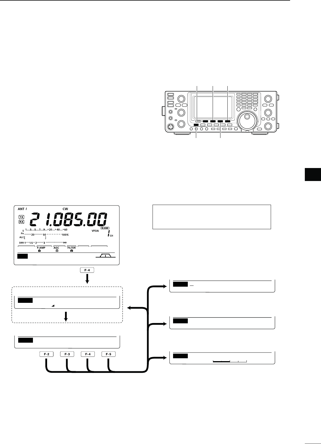
38
4
RECEIVE AND TRANSMIT
1
2
3
4
5
6
7
8
9
10
11
12
13
14
15
16
17
18
19
20
21
N%LECTRONICKEYERFUNCTIONS
You can access a number of convenient functions
of the built-in electronic keyer in the memory keyer
menu.
q
In the CW mode,
push [MENU] to display the “M1”
screen (Menu 1).
w Push [KEY](F-4) to display the “KEY” screen (Mem-
ory Keyer).
e Push [SEND](F-2), [EDT](F-3), [001](F-4) or [SET]
(F-5) to select the desired menu.
See the diagram below.
s0USH;-%.5=TOSAVEANDRETURNTOTHEPREVIOUSDIS-
play.
AGC 1⁄4 KEY SCP
M1
SEND EDT 001 SET
KEY
1
Normal
001
Number Style
1
50%
SET
Side Tone Level
DEL SPC
EDT CQ TEST CQ TEST DE
M1
M1 M2 M3 M4 –1
SEND
001
s-EMORY+EYERSCREEN
s+EYER3ENDSCREEN (p. 39)
s+EYER%DITSCREEN (p. 40)
s#ONTEST.UMBER3ETMODE (p. 41)
s+EYER3ETMODE (p. 42)
[F-2]
[F-3]
[F-4]
[F-5]
[MENU]
[MENU] [KEY]/[001]
[EDT] [SET][SEND]
D-EMORYKEYERMENUCONSTRUCTION
The screen you want to appear first can be
selected in the “KEYER 1st Menu” item of
the Set mode. (p. 88)
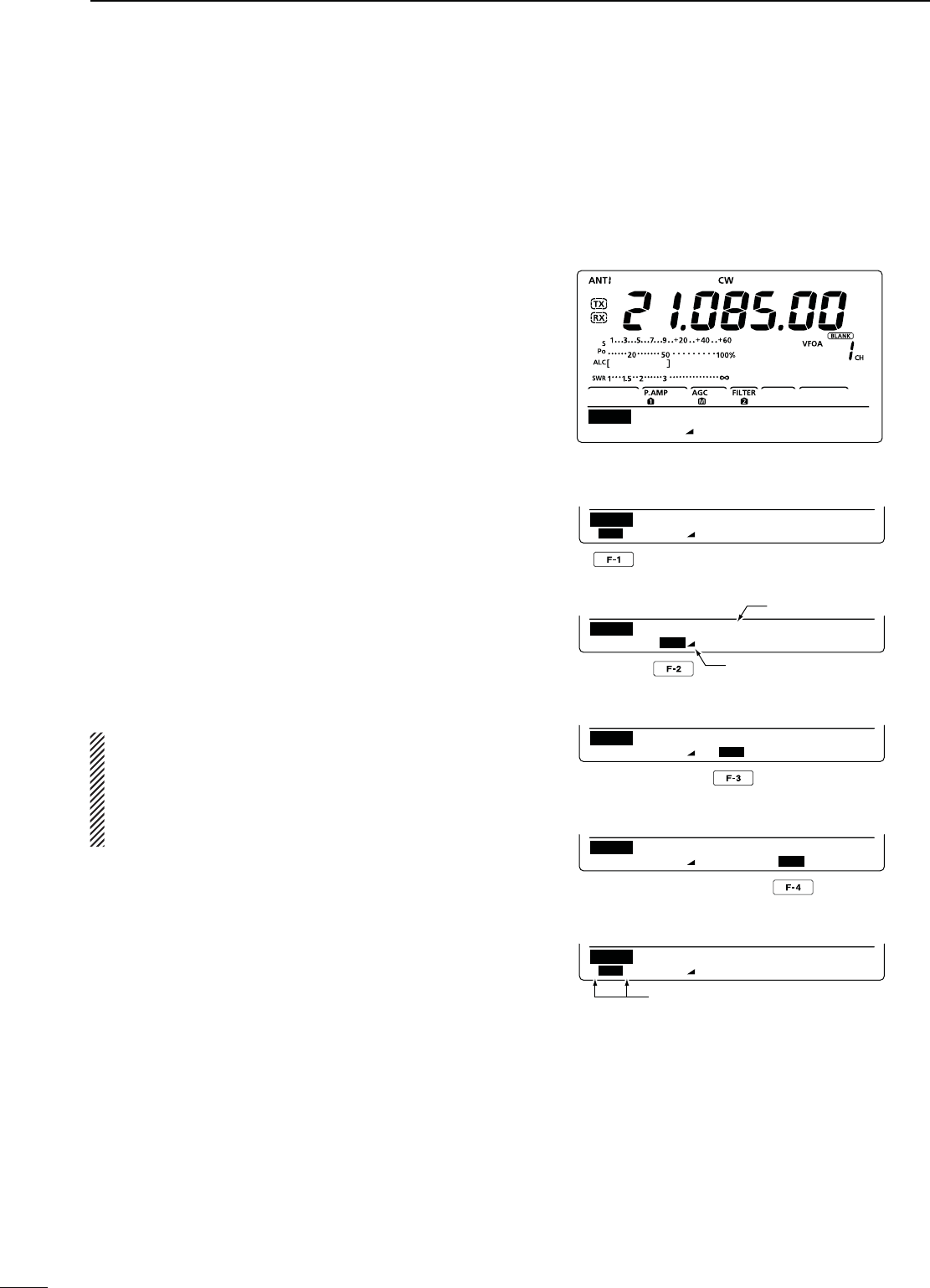
39
4RECEIVE AND TRANSMIT
N Electronic keyer functions (continued)
D-EMORYKEYERSENDMENU
Pre-set characters can be sent using the Keyer Send
menu. Contents of the memory keyer are set in the
Edit menu.
s4RANSMITTING
q
In the CW mode, p
ush [MENU] to display the “M1”
screen (Menu 1).
w Push [KEY](F-4) to display the “KEY” screen (Mem-
ory Keyer).
e Push [SEND](F-2) to display the “SEND” screen
(Keyer Send).
r Push [TRANSMIT] to switch the transceiver to
transmit, or turn ON the Break-in function. (p. 63)
t Push one of the function keys, [M1](F-1) to
[M4](F-4), to send the memory keyer contents.
s(OLDINGDOWNAFUNCTIONKEYFORSECONDREPEATEDLY
sends the contents; push any function key to cancel the
transmission.
s4HECONTESTSERIALNUMBERCOUNTERADVANCESEACHTIME
the contents are sent.
s0USH;=&TOREDUCETHECONTESTSERIALNUMBERAD-
vances by 1 before sending the memory keyer contents
to a station a second time.
s3ETTHEMEMORYKEYERREPEATINTERVALTOBETWEENAND
60 seconds (1 second steps) in the “Keyer Repeat Time”
item of the Keyer Set mode. (p. 42)
y Push [MENU], and return to the “KEY” screen.
u
Push [MENU] again to return to the “M1” screen.
For your information
When an external keypad is connected to pin 3 and
pin 7 of the [MIC] connector, the contents of M1 to
M4 can be transmitted without selecting the keyer
send menu.
See page 92 for details.
M1 M2 M3 M4 –1
SEND
001
CQ TEST CQ TE
M1 M2 M3 M4 –1
SEND
001
UR 5NN001 BK
M1 M2 M3 M4 –1
SEND
001
CFM TU
M1 M2 M3 M4 –1
SEND
001
QRZ?
M1 M2 M3 M4 –1
SEND
001
CQ TEST CQ TE
M1][M2M3M4–1
SEND
001
s-SENDINGDISPLAY
s-SENDINGDISPLAY
s-SENDINGDISPLAY
s-SENDINGDISPLAY
s7HILETRANSMITTINGREPEATEDLY
Counter
Count up trigger icon
“ [ ” and “ ] ” appear
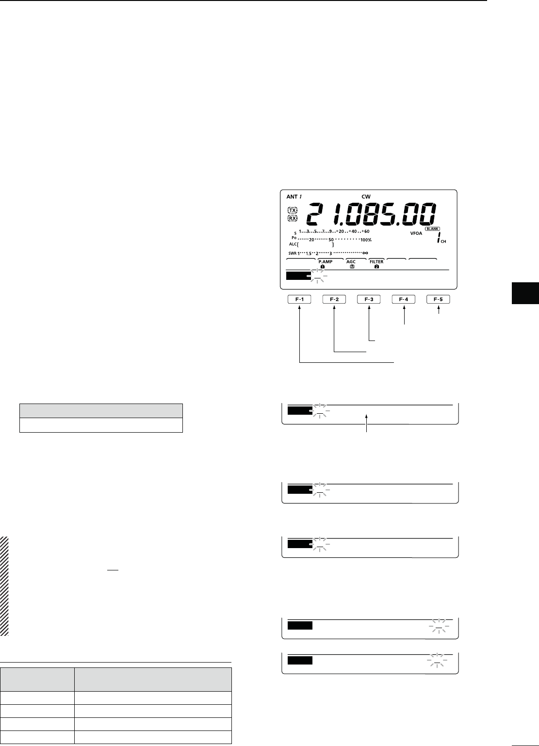
40
4
RECEIVE AND TRANSMIT
1
2
3
4
5
6
7
8
9
10
11
12
13
14
15
16
17
18
19
20
21
D%DITINGAMEMORYKEYER
The contents of the memory keyer memories can be
set using the memory keyer edit menu. The memory
keyer can memorize and re-transmit 4 CW key codes
for often-used CW sentences, contest serial numbers
or a count up trigger. The total capacity of the memory
keyer is 70 characters per memory channel.
s0ROGRAMMINGCONTENTS
q
In the CW mode, p
ush [MENU] to display the “M1”
screen (Menu 1).
w Push [KEY](F-4) to display the “KEY” screen (Mem-
ory Keyer).
e Push [EDT](F-3) to display the “EDT” screen (Keyer
Edit).
s4HE MEMORY KEYER CONTENT OF #HANNEL - IS DIS-
played.
r Push [F-1] one or more times to select the memory
keyer channel to be edited.
t Rotate [DIAL] to select a character, or push the
keypad to input a number.
s0USH;$%,=&TODELETETHE SELECTED CHARACTEROR
number.
s0USH;30#=&TOINPUTASPACE
s!NERRORBEEPSOUNDSWHENYOUTRYTOINPUTMORETHAN
70 characters. To delete a character or number, push
[Ω](F-2) or [≈](F-3) to select it, then push [DEL](F-4) to
delete.
3ELECTABLECHARACTERS
A to Z ⁄ ? ^ . , @ 1
y Push [Ω](F-2) to move the cursor backward, or push
[≈](F-3) to move the cursor forward.
u Repeat steps t and y to program up to 70 char-
acters memory keyer contents.
i Push [MENU] to save, and return to the “KEY”
screen.
o
Push [MENU] again to return to the “M1” screen.
./4%
“^” is used to transmit a string of characters with no
inter-character space. Put “^” before a text string such
as ^AR, and the string “AR ” is sent with no space.
“1” is used to insert the CW contest serial num-
ber. The serial number automatically advances
by 1. This function is available for only one mem-
ory keyer channel at a time. “1” is used in memory
keyer channel M2 by default.
0REPROGRAMMEDMEMORYKEYERCONTENTS
-EMORYKEYER
CHANNEL #ONTENTS
M1 CQ TEST CQ TEST DE JA1 JA1 TEST
M2 UR 5NN1 BK
M3 CFM TU
M4 QRZ?
Input a space
Delete a character
Move cursor forward
Move cursor backward
Select M1 to M4
DEL SPC
EDT CQ TEST CQ TEST DE
M1
DEL SPC
EDT TU DE JA3YUA TEST
M3
DEL SPC
EDT QSL TU DE JA3YUA
M3
DEL SPC
EDT UR 5NNMBK
M2
DEL SPC
EDT CFM TU
M3
DEL SPC
EDT QRZ?
M4
s-DEFAULTINDICATION
s-DEFAULTINDICATION
s-DEFAULTINDICATION
%XAMPLE DISPLAY— Inputting “QSL TU
DE JA3YUA TEST” into the memory keyer
channel 3 (M3).
When inputting an asterisk, the
counter is incremented by 1.
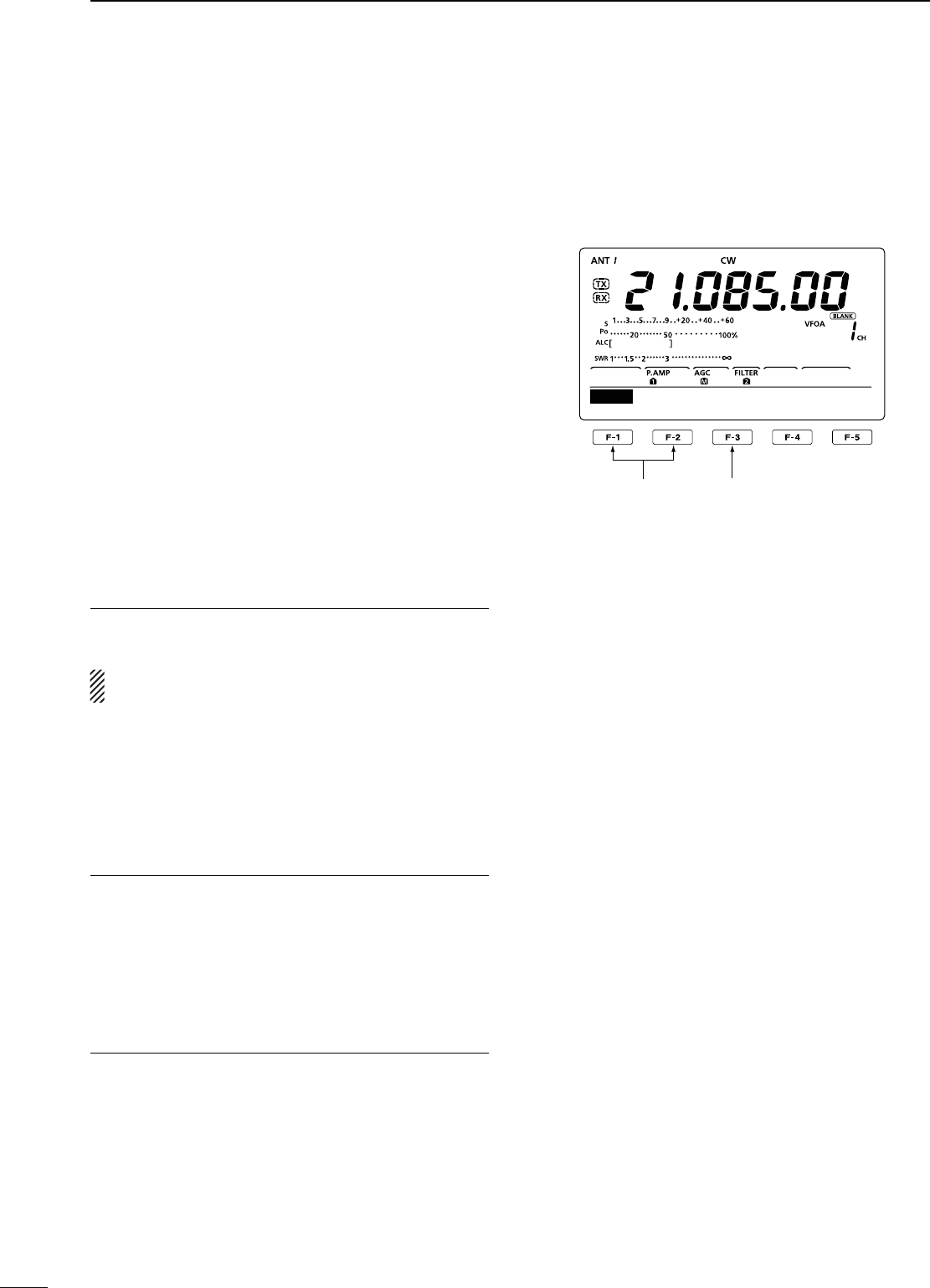
41
4RECEIVE AND TRANSMIT
N Electronic keyer functions (continued)
D#ONTESTNUMBER3ETMODE
This mode is used to set the contest number and count
up trigger, etc.
s3ETTINGCONTENTS
q
In the CW mode, p
ush [MENU] to display the “M1”
screen (Menu 1).
w Push [KEY](F-4) to display the “KEY” screen (Mem-
ory Keyer).
e Push [001](F-4) to enter the Contest Number Set
mode.
r Push [Y](F-1) or [Z](F-2) to select the desired
item.
t Rotate [DIAL] to select the desired option.
s(OLDDOWN;&=FORSECONDTORESETTOTHEDEFAULTSET-
ting, if desired.
y Push [MENU] to save, and return to the “KEY”
screen.
u
Push [MENU] again to return to the “M1” screen.
.UMBER3TYLE1. $EFAULT.ORMAL
This item sets the numbering system used for contest
numbers— normal or short morse numbers.
Short morse numbers are also referred to as “cut”
numbers.
s.ORMAL $OESNOTUSESHORTMORSENUMBERS
sANO : Sets 1 as A, 9 as N and 0 as O.
sANT : Sets 1 as A, 9 as N and 0 as T.
s NO : Sets 9 as N and 0 as O.
s NT : Sets 9 as N and 0 as T.
#OUNT5P4RIGGER2. $EFAULT-
Set the count-up trigger to one of four memory slots
for the contest number exchange. The count-up trigger
allows the contest number to automatically advance
after each complete serial number exchange is sent.
s---OR-CANBESET
0RESENT.UMBER3. $EFAULT5P$OWN
This item shows the current number for the count-up
trigger channel set above.
s2OTATE;$)!,=TOCHANGETHENUMBERORHOLDDOWN
[F-3](CLR) for 1 second to reset the current number
to 001.
1
Normal
001
Number Style
Select the item Reset to the default
setting
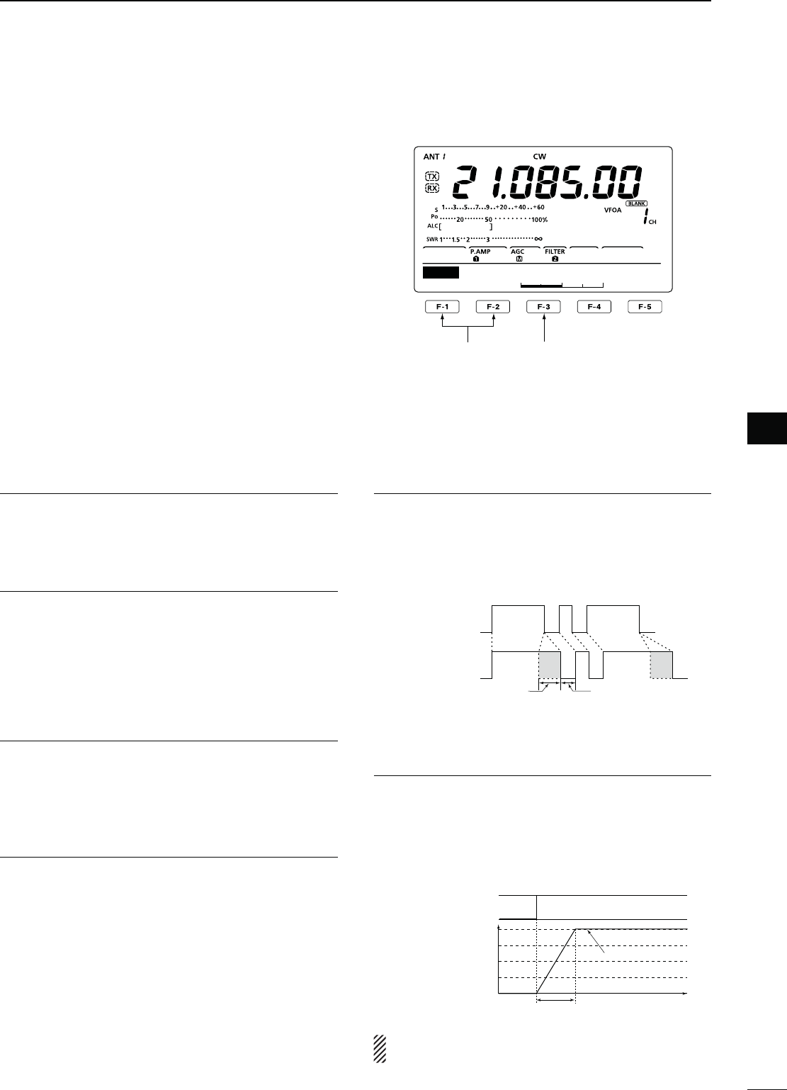
42
4
RECEIVE AND TRANSMIT
1
2
3
4
5
6
7
8
9
10
11
12
13
14
15
16
17
18
19
20
21
D+EYER3ETMODE
This Set mode is used to set the CW sidetone, mem-
ory keyer repeat time, dash weight, paddle specifica-
tions, keyer type, etc.
s3ETTINGCONTENTS
q
In the CW mode, p
ush [MENU] to display the “M1”
screen (Menu 1).
w Push [KEY](F-4) to display the “KEY” screen (Mem-
ory Keyer).
e Push [SET](F-5) to enter the Keyer Set mode.
r Push [Y](F-1) or [Z](F-2) to select the desired
item.
t Rotate [DIAL] to select the desired option.
s(OLDDOWN;&=FORSECONDTORESETTOTHEDEFAULTSET-
ting, if desired.
y Push [MENU] to save, and return to the “KEY”
screen.
u
Push [MENU] again to return to the “M1” screen.
3IDE4ONE,EVEL1. $EFAULT
Select the CW sidetone output level.
sTOINSTEPSCANBESELECTED
3IDE4ONE,,IMIT2. $EFAULT/.
Set the CW sidetone level limit. When the [AF] con-
trol is rotated above a specified level, the CW sidetone
does not increase.
s/. #7SIDETONELEVELISLIMITED
s/&SIDETONELEVELISNOTLIMITED
Keyer 3. 2EPEAT4IME $EFAULTS
When sending CW using the repeat timer, this item
sets the time between transmission.
sTOSECONDSINSECONDSTEPSCANBESELECTED
-ESSAGE$ISPLAY4. $EFAULT.ORMAL
When you are in the “SEND” screen (Keyer Send),
channel numbers are displayed above the function
keys. However, you can display the first three charac-
ters of the keyer memory instead of the channel num-
ber.
Select whether to display the channel number or the
first three characters of the keyer.
s.ORMAL $ISPLAYSTHECHANNELNUMBER
s-ESSAGE$ISPLAYSTHElRSTTHREECHARACTERSOFTHE
keyer memory.
$OT$ASH2ATIO5. $EFAULT
Set the dot/dash ratio.
sTOINSTEPSCANBESELECTED
+EYINGWEIGHTEXAMPLEMorse code “K”
DASH
Weight setting:
1:1:3 (default)
Weight setting:
Adjusted
DASH
DOT (fixed*)
Adjustable range SPACE (fixed*)
*SPACE and DOT length can be
adjusted with only [KEY SPEED].
2ISE4IME6. $EFAULTMS
This item sets the rise time of the transmitted CW en-
velope.
sORMILLISECONDSCANBESELECTED
!BOUTRISETIME
Key action
Tx output power
Rise time
Tx
Rx
Set Tx power level
Time
0
If the rise time of a CW waveform is too short, key
clicks on nearby frequencies can be generated.
Continued on the next page.
1
50%
SET
Side Tone Level
Select the item Reset to the default
setting

43
4RECEIVE AND TRANSMIT
D Keyer set mode (continued)
0ADDLE0OLARITY7. $EFAULT./2-!,
Set the paddle polarity.
s.ORMALORREVERSEPOLARITYCANBESELECTED
Keyer Type 8. $EFAULT%,%#+%9
Select the keyer type for the [ELEC-KEY] connector
on the front panel.
s3TRAIGHTKEY"5'+%9OR%,%#+%9CANBESE-
lected.
MIC Up/Down Keyer 9. $EFAULT/&&
Set the microphone [UP]/[DN] switches to be used
as a key. (The microphone [UP]/[DN] switches do not
work as a ‘squeeze key.’)
s/. 4HE;50=;$.=SWITCHESCANBEUSEDASAKEY
for CW.
s/&&4HE;50=;$.=SWITCHESCANNOTBEUSEDASA
key for CW.
./4%When “ON” is selected, the frequency and
memory channels cannot be changed using the
[UP]/[DN] switches.
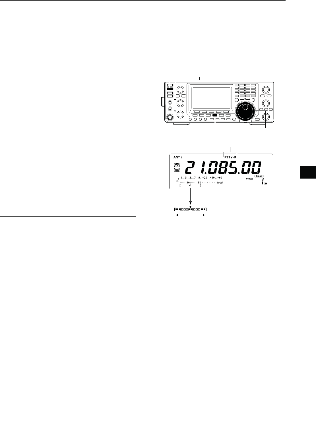
44
4
RECEIVE AND TRANSMIT
1
2
3
4
5
6
7
8
9
10
11
12
13
14
15
16
17
18
19
20
21
N/PERATING2449&3+
When using your RTTY terminal or TNC, consult the
manual that comes with the equipment.
q Select the desired band. (p. 25)
w Push [RTTY] to select the RTTY mode.
s0USHING;2449=ALTERNATELYSELECTSTHE2449OR2449
reverse mode.
e Rotate [DIAL] to tune a desired signal.
s4HE3METERINDICATESRECEIVEDSIGNALSTRENGTH
s)FTHERECEIVEDSIGNALCANNOTBEDEMODULATEDTRYTOSE-
lect the RTTY reverse mode in step w.
s4HETUNINGSTEPCANBECHANGEDINTHETUNINGSTEPPRO-
gram mode. (p. 27)
r Push [TRANSMIT] to set the transceiver to the
transmit mode, or transmit a SEND signal from your
TNC.
s4HE48INDICATORLIGHTSRED
s4HE0OMETER DISPLAYS THE TRANSMITTED2449SIGNAL
strength.
t Use your PC or TNC (TU) to transmit RTTY (FSK)
signals.
y Push [TRANSMIT] to return to receive.
#ONVENIENT2ECEIVEFUNCTIONS
s0REAMPANDATTENUATORP
s4WIN0"40ASSBAND4UNINGP
s!'#!UTO'AIN#ONTROLP
s.OISE"LANKERP
s.OISE2EDUCTIONP
s.OTCHlLTERP
s¼ function (p. 27)
sTwin Peak Filter (p. 47)
[RTTY] [DIAL]
[TRANSMIT] TX indicator
“RTTY” or “RTTY-R” appears
While receiving, the meter functions as the
RTTY tuning meter to make correct tuning
easier.
Rotate [DIAL] to the point where both sides of
the dots appear equally.
* While transmitting, the meter functions as the trans-
MITMETERSELECTEDBYPUSHING;!.4s-%4%2=
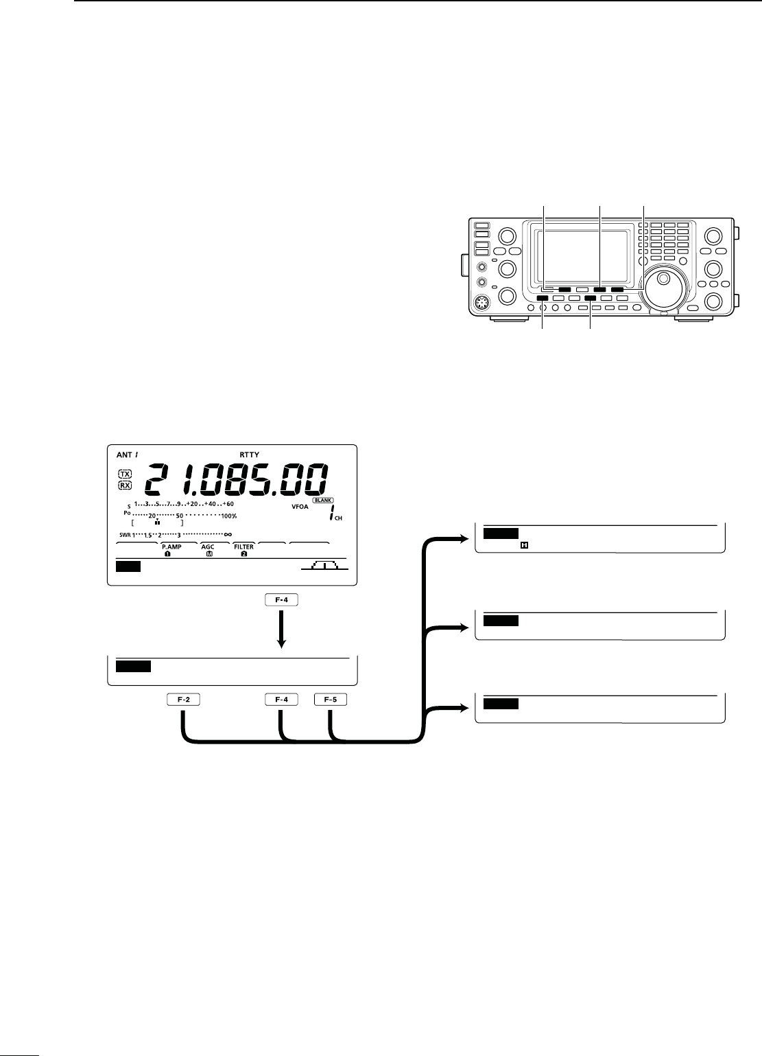
45
4RECEIVE AND TRANSMIT
N2449FUNCTIONS
The RTTY menu has a number of convenient functions
for RTTY operation.
q
Push [RTTY]
to select the RTTY mode.
s0USHING;2449=ALTERNATELYSELECTSTHE2449OR2449
reverse mode.
w Push [MENU] to display the “M1” screen (Menu 1).
e Push [RTTY](F-4) to display the “RTTY” screen.
r Push [DEC](F-2), [TPF](F-4) or [SET](F-5) to select
the desired menu. See the diagram below.
s0USH;-%.5=TORETURNTOTHEPREVIOUSDISPLAY
D2449MENUCONSTRUCTION
[MENU] [RTTY]
[RTTY]/[TPF] [SET][DEC]
AGC 1/4 RTTY S CP
M1
DEF TPF SET
RTTY
RTTY
RTTY–TPF ON
1
2125
SET
RTTY Mark Freq
DEC
45BPS BAUDOT
MK ⁄ SFT 2125 ⁄ 170
F2 : HOLD F3 : CLR
ADJ
DEF TPF SET
H
s2449SCREEN
s2449$ECODERSCREEN (p. 46)
s4WIN0EAK&ILTERSETTINGSCREEN (p. 47)
s24493ETMODE (p. 48)
[F-2]
[F-4]
[F-5]
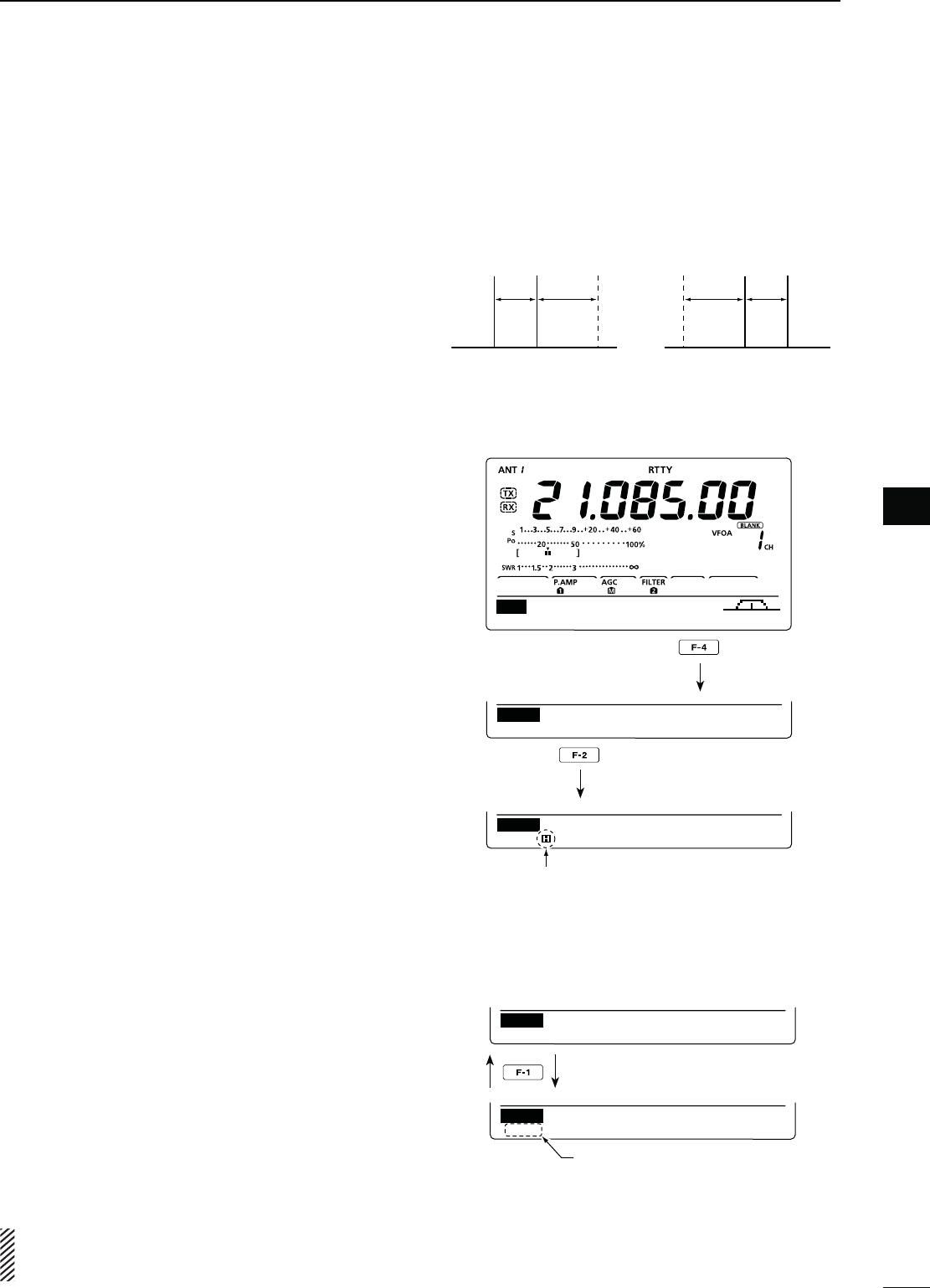
46
4
RECEIVE AND TRANSMIT
1
2
3
4
5
6
7
8
9
10
11
12
13
14
15
16
17
18
19
20
21
D!BOUTTHE2449REVERSEMODE
Received characters are occasionally garbled when
the Mark and Space signals are reversed. This rever-
sal can be caused by incorrect TNC connections, set-
ting or commands.
To receive reversed RTTY signals correctly, select the
RTTY reverse mode.
± Push [RTTY] to alternately select the RTTY mode
or RTTY reverse mode.
D2449DECODER
The transceiver has an RTTY decoder for Baudot
(mark freq.: 2125 Hz, shift freq.: 170 Hz, 45 bps).
An external terminal unit (TU) or terminal node con-
nector (TNC) is not necessary for receiving a Baudot
signal.
q In the RTTY mode, push [MENU] to display the “M1”
screen (Menu 1).
w Push [RTTY](F-4) to display the “RTTY” screen.
e Push [F-2](DEC) to turn ON the RTTY decoder.
s2449DECODERSCREENAPPEARS
r Push [F-2] to turn ON the Hold function to hold the
current screen.
shH” appears when this function is turned ON.
s0USH;&=AGAINTOTURN/&&THE(OLDFUNCTION
t Hold down [F-3] for 1 second to clear the displayed
characters, if desired.
shH” disappears at the same time as the displayed char-
acters are cleared. (The hold function is cancelled.)
y Push [MENU] to return to the previous display.
s3ETTINGTHEDECODERTHRESHOLDLEVEL
If some characters are displayed when no signal is re-
ceived, adjust the RTTY decoder threshold level.
q Select the RTTY decoder screen as described
above.
w Push [F-1](ADJ) to select the threshold level adjust-
ment mode.
e Rotate [DIAL] to adjust the RTTY decoder threshold
level.
s(OLDDOWN;&=FORSECONDTORESETTOTHEDEFAULTSET-
ting, if desired.
r Push [MENU] to save, and return to the previous
display.
The number of the decoder display lines, the Un-
Shift On Space (USOS) function and new line code
can be set in the RTTY Set mode. (p. 48)
Normal Reverse
170
Hz
170
Hz
2125
Hz
2125
Hz
BFOBFO Space
Space Mark
Mark
AGC 1/4 RTTY S CP
M1
DEC TPF SET
RTTY
DEC
45BPS BAUDOT
MK ⁄ SFT 2125 ⁄ 170
F2 : HOLD F3 : CLR
ADJ
H
Appears when the Hold function
is turned ON.
DEC
45BPS BAUDOT
MK ⁄ SFT 2125 ⁄ 170
F2 : HOLD F3 : CLR
9
DEC
45BPS BAUDOT
MK ⁄ SFT 2125 ⁄ 170
F2 : HOLD F3 : CLR
ADJ
Threshold level display
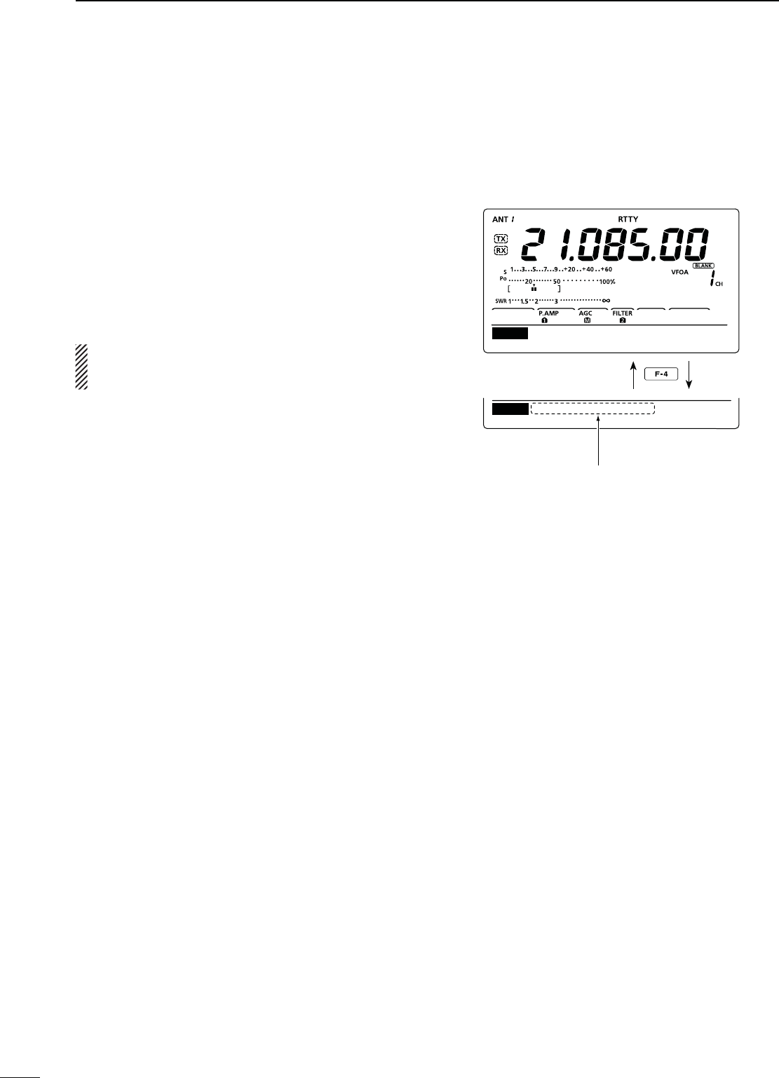
47
4RECEIVE AND TRANSMIT
N RTTY functions (continued)
D4WIN0EAK&ILTER
The Twin Peak Filter changes the receive frequency
response by boosting 2125 and 2295 Hz for better
copying of RTTY signals.
q In the RTTY mode, push [MENU] to display the “M1”
screen (Menu 1).
w Push [RTTY](F-4) to display the “RTTY” screen.
e Push [TPF](F-4) to turn the Twin Peak Filter ON or
OFF.
r Push [MENU] to save, and return to the previous
display.
./4%When the Twin Peak Filter is in use, the re-
ceived audio output may increase. This is normal;
not a malfunction.
DEC TPF SET
RTTY
RTTY
RTTY–TPF ON
DEC TPF SET
Appears when the Twin Peak
Filter is ON.

48
4
RECEIVE AND TRANSMIT
1
2
3
4
5
6
7
8
9
10
11
12
13
14
15
16
17
18
19
20
21
D24493ETMODE
The RTTY Set mode is used to set the mark and shift
frequencies, keying type, decode USOS function,
RTTY decoder new line code and the number of de-
code screen display lines.
s3ETTINGCONTENTS
q
In the RTTY mode, p
ush [MENU] to display the “M1”
screen (Menu 1).
w Push [RTTY](F-4) to display the “RTTY” screen.
e Push [SET](F-5) to enter the RTTY Set mode.
r Push [Y](F-1) or [Z](F-2) to select the desired
item.
t Rotate [DIAL] to select the desired option.
s(OLDDOWN;&=FORSECONDTORESETTOTHEDEFAULTSET-
ting, if desired.
y Push [MENU] to save, and return to the “RTTY”
screen.
u
Push [MENU] again to return to the “M1” screen.
2449-ARK&REQ1. $EFAULT
Select the RTTY mark frequency.
sAND(ZARESELECTABLE
24493HIFT7IDTH2. $EFAULT
Select the RTTY frequency shift.
sAND(ZARESELECTABLE
2449+EYING0OL3. $EFAULT./2-!,
Select normal or reverse keying polarity.
s./2-!, +EYOPENCLOSE-ARK3PACE
s2%6%23%+EYOPENCLOSE3PACE-ARK
$ECODE53/34. $EFAULT/.
Turn the USOS (UnShift On Space) function ON or
OFF. This function decodes a letter code after receiv-
ing a “space.”
s/&&$ECODESASACHARACTERCODE
s/. $ECODESASALETTERCODE
$ECODE.EW,INE5. $EFAULT#2,,&
Select the internal RTTY decoder new line code.
CR: Carriage Return, LF: Line Feed
s#2,,&-AKESANEWLINEWITHANYCODE
s#2,& -AKES A NEW LINE WITH ONLY THE
CR+LF code.
$ECODE3CREEN6. $EFAULTLINE
Set the decoder screen display mode to 2 or 3 lines.
1
2125
SET
RTTY Mark Freq
Select the item
Reset to the default
setting

49
4RECEIVE AND TRANSMIT
[DIAL][AM/FM][AF][MIC]
Band keys
[TRANSMIT] TX indicator
N/PERATING!-&-
q Select the desired band. (p. 25)
w Push [AM/FM] to select the AM or FM mode.
s)FDESIREDAFTER!-OR&-ISSELECTEDHOLDDOWN;!-
FM] for 1 second to select the data mode.
e Rotate [DIAL] to tune a desired signal.
s4HE3METERDISPLAYSTHERECEIVEDSIGNALSTRENGTH
s4HETUNINGSTEPCANBECHANGEDINTHETUNINGSTEPPRO-
gram mode. (p. 27)
r Rotate the [AF] control to adjust the audio to a com-
fortable listening level.
t Push [PTT] on the microphone to transmit (or
[TRANSMIT] on the transceiver).
s4HE48INDICATORLIGHTSRED
y Speak into the microphone at your normal voice
level.
s2OTATETHE;-)#=CONTROLTOADJUSTTHEMICROPHONEGAIN
in this step, if necessary.
u Release [PTT] to receive (or push [TRANSMIT]
again).
#ONVENIENT2ECEIVEFUNCTIONS
s0REAMPANDATTENUATORP
s4WIN0"40ASSBAND4UNINGP
s!'#!UTO'AIN#ONTROLP
s.OISE"LANKERP
s.OISE2EDUCTIONP
s.OTCHlLTERP
s63#6OICE3QUELCH#ONTROLP
*AM only
#ONVENIENTFUNCTIONSFORTRANSMIT
s3PEECH#OMPRESSORP
s6/86OICE/PERATED4RANSMITP
s4RANSMITQUALITYMONITORP
s!UDIOTONECONTROLP
Appears
s!-MODE
s&-MODE
Appears
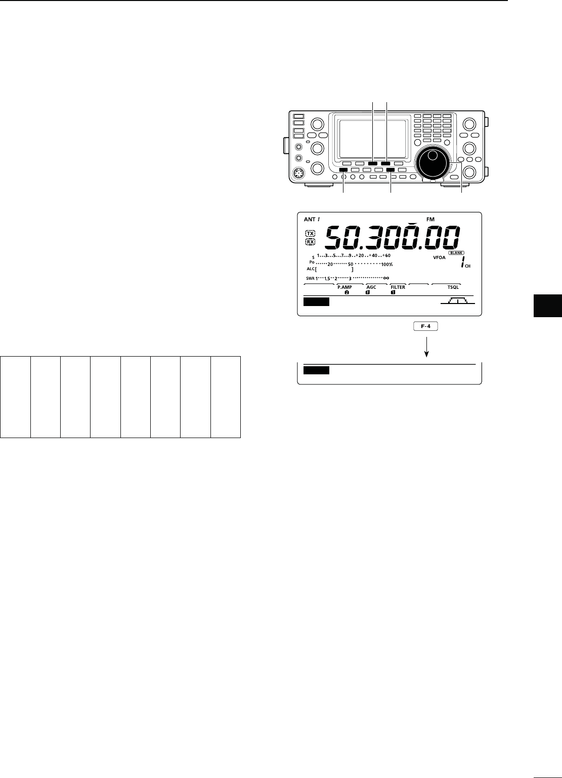
50
4
RECEIVE AND TRANSMIT
1
2
3
4
5
6
7
8
9
10
11
12
13
14
15
16
17
18
19
20
21
4ONESQUELCHOPERATION
The tone squelch opens only when you receive a sig-
nal containing a matching subaudible tone. You can
silently wait for calls from others using the same tone.
q Push [AM/FM] once or twice to select the FM
mode.
w Push [MENU] to display the “M1” screen (Menu 1).
e Push [TON](F-4) one or more times to turn ON the
Tone Squelch function.
sh431,vAPPEARS
r Hold down [TON](F-4) for 1 second to display the
“TON” screen (Tone).
sh431,4ONEvAPPEARSONTHEFUNCTIONDISPLAY
t Rotate [DIAL] to select the desired tone squelch
frequency. (See the table shown below.)
s(OLDDOWN;&=FORSECONDTORESETTOTHEDEFAULTSET-
ting, if desired.
y Push [MENU] to save, and exit the “TON” screen.
u Communicate in the usual manner.
s!VAILABLETONESQUELCHFREQUENCIES (Unit: Hz)
67.0
69.3
71.9
74.4
77.0
79.7
82.5
085.4
088.5
091.5
094.8
097.4
100.0
103.5
107.2
110.9
114.8
118.8
123.0
127.3
131.8
136.5
141.3
146.2
151.4
156.7
159.8
162.2
165.5
167.9
171.3
173.8
177.3
179.9
183.5
186.2
189.9
192.8
196.6
199.5
203.5
206.5
210.7
218.1
225.7
229.1
233.6
241.8
250.3
254.1
[TON][F-3]
[AM/FM] [DIAL][MENU]
DUPAGC AFC TON SCP
M1
TON
SCANTON 88.5Hz
TSQL Tone
Hold down
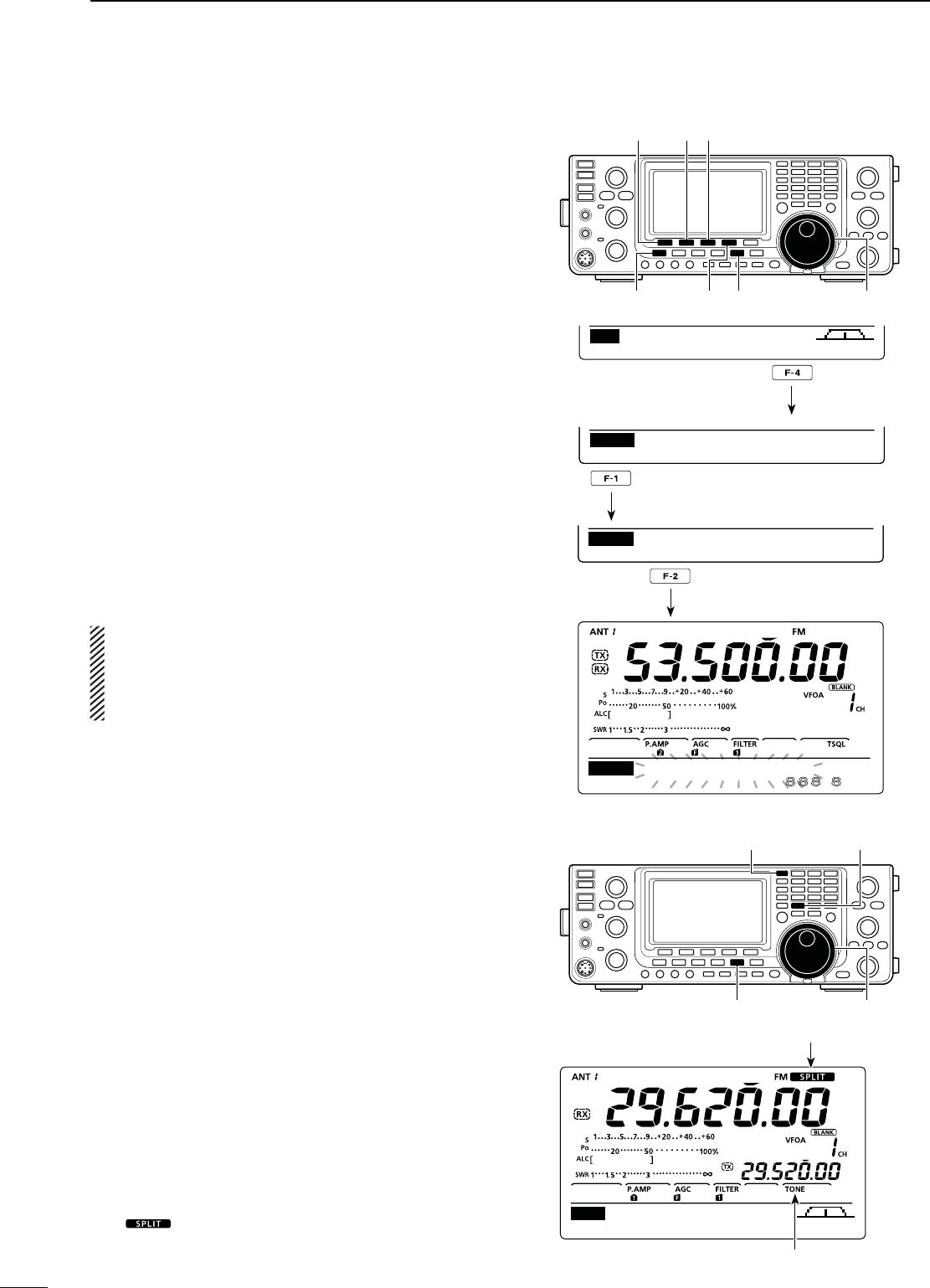
51
4RECEIVE AND TRANSMIT
To search for a repeater’s sub-audible tone, a tone
scan is available.
By monitoring a repeater signal with a tone squelch,
you can determine the tone frequency necessary to
open the repeater or the squelch.
q In the FM mode, push [MENU] to display the “M1”
screen (Menu 1).
w Hold down [TON](F-4) for 1 second to enter the
“TON” screen (Tone).
e Push [TON](F-1) one or more times to select the
tone type to be scanned.
sh2PTR4ONEvFORAREPEATERTONEANDh431,4ONEvFOR
tone squelch can be selected.
r Push [SCAN](F-2) to start the Tone scan.
sh2PTR4ONE3#!.vORh431,4ONE3#!.vBLINKSDE-
pending on the type you selected.
t When a matched tone is found, the scan pauses
and the sub-audible tone frequency is automatically
programmed.
s(OLDDOWN;&=FORSECONDTOSELECTADEFAULTSETTING
if desired.
y Push [SCAN](F-2) to cancel the Tone scan.
When the tone scan is used in the Memory channel
mode, the detected tone frequency can be used
temporarily.
To save the detected tone frequency setting, you
must over-write the Memory channel data. (p. 70)
N4ONESCANOPERATION
Repeater operation
A repeater receives transmitted signals and re-trans-
mits them on a different frequency. When using a re-
peater, the transmit frequency is shifted from the re-
ceive frequency by a frequency offset.
A repeater can be accessed using the split frequency
operation to set the frequency shift to the same value
as the repeater’s frequency offset.
q First, set the frequency offset for the HF and 50
MHz bands in the “FM SPLIT Offset HF” and “FM
SPLIT Offset 50M” items, and set the “Quick SPLIT”
item to “ON” in the Set mode. (p. 86)
w Push [VFO/MEMO] to select the VFO mode.
e Select the desired band. (p. 25)
r Push [AM/FM] to select the FM mode.
t R
otate
[DIAL] to set the receive frequency (repeater
output frequency).
y Hold down [SPLIT] to turn ON the Quick Split func-
tion.
sh ” and “TONE” appear.
s4HETONEFREQUENCYCANBESETINTHEh4/.vSCREEN
(Tone). 88.5 Hz is set by default. (p. 52)
u Communicate in the normal way.
[TON] [SCAN] [F-3]
[MENU] [AM/FM][TON] [DIAL]
AGC TON SCP
M1
88.5Hz
TO N SCAN
TON Rptr
Tone
.Hz
SCAN
TSQL
Tone SACN
TON
88.5Hz
TO N SCAN
TON TSQL
Tone
Hold down
Push to select the tone type.
Push to start or cancel the scan.
[DIAL]
[VFO/MEMO] [SPLIT]
[AM/FM]
AGC TON SCP
M1
Appears
Appears
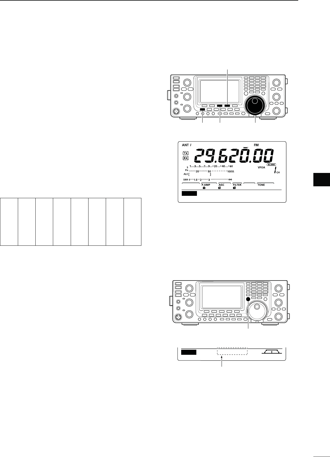
52
4
RECEIVE AND TRANSMIT
1
2
3
4
5
6
7
8
9
10
11
12
13
14
15
16
17
18
19
20
21
D2EPEATERACCESSTONEFREQUENCYSETTING
Some repeaters require a subaudible tone to be ac-
cessed. Subaudible tones are superimposed on your
normal signal and must be set first. You can select 50
tones from 67.0 Hz to 254.1 Hz.
q
In the FM mode, p
ush [MENU] to display the “M1”
screen (Menu 1).
w Push [TON](F-4) one or more times to turn ON the
Tone Encoder function.
sh4/.%vAPPEARS
e Hold down [TON](F-4) for 1 second to display the
“TON” screen (Tone).
sh2PTR4ONEvAPPEARSONTHEFUNCTIONDISPLAY
r Rotate [DIAL] to select the desired repeater tone
frequency. (See the table below.)
t Push [MENU] to save, and exit the “TON” screen.
s!VAILABLETONEFREQUENCIES (unit: Hz)
67.0
69.3
71.9
74.4
77.0
79.7
82.5
85.4
088.5
091.5
094.8
097.4
100.0
103.5
107.2
110.9
114.8
118.8
123.0
127.3
131.8
136.5
141.3
146.2
151.4
156.7
159.8
162.2
165.5
167.9
171.3
173.8
177.3
179.9
183.5
186.2
189.9
192.8
196.6
199.5
203.5
206.5
210.7
218.1
225.7
229.1
233.6
241.8
250.3
254.1
D4RANSMITFREQUENCYMONITORCHECK
You may be able to directly receive the other party’s
transmitted signal without having to go through a re-
peater. This function helps you to check whether or
not the direct communication can be done.
± While receiving, hold down [XFC] to see if you can
directly receive the other party’s transmitted signal.
s7HILEHOLDINGDOWN;8&#=THEOFFSETDIRECTIONANDFRE-
quency offset are displayed on the function display.
Offset direction and frequency
AGC TON SCP
M1 –100.0k
[XFC]
[MENU] [F-3]
[TON]
[DIAL]
SCANTON 88.5Hz
Rptr Tone
TON
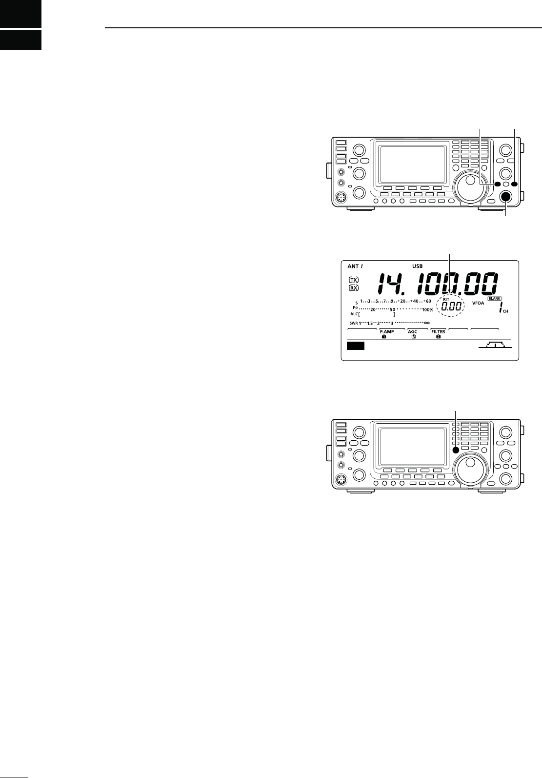
5
53
FUNCTIONS FOR RECEIVE
N2)4FUNCTION
The RIT (Receive Increment Tuning) function com-
pensates for off-frequency operation of the received
station.
The function shifts the receive frequency up to
±9.99 kHz in 10 Hz steps*, without changing the trans-
mit frequency.
* The [RIT/∂TX] control tunes in 1 Hz steps when the operat-
ing frequency readout is set to the 1 Hz step readout.
q Push [RIT] to turn ON the RIT function.
sh2)4vANDTHEFREQUENCYSHIFTAPPEARWHENTHISFUNCTION
is ON.
w Rotate the [RIT/∂TX] control.
s(OLDDOWN;#,%!2=FORSECONDTORESETTHE2)4FRE-
quency.
s0USH;#,%!2=MOMENTARILYTORESETTHE2)4FREQUENCY
when the “Quick RIT Clear” item is set to “ON” in the Set
mode. (p. 88)
s(OLDDOWN;2)4=FORSECONDTOADDTHEFREQUENCYSHIFT
to the operating frequency, if desired.
e To cancel the RIT function, push [RIT] again.
sh2)4vANDTHEFREQUENCYSHIFTDISAPPEAR
D2)4MONITORFUNCTION
When the RIT function is ON, holding down [XFC] al-
lows you to listen to the displayed frequency (RIT is
temporarily cancelled).
Appear
[RIT] [CLEAR]
[RIT/∂TX]
AGC TBW SCP
M1
[XFC]
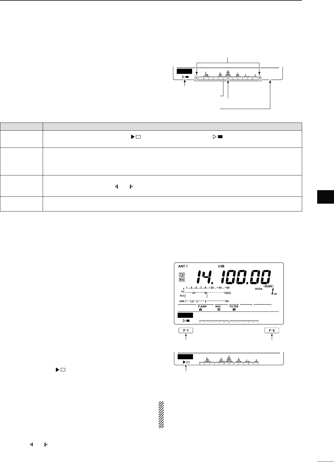
54
5
FUNCTIONS FOR RECEIVE
1
2
3
4
5
6
7
8
9
10
11
12
13
14
15
16
17
18
19
20
21
N3IMPLEBANDSCOPE
The Band Scope function allows you to visually check
the location and strength of signals around a specified
frequency.
The IC-7410’s Band Scope function can be used in
any operating mode and any frequency band.
INDICATOR DESCRIPTION
3WEEPICON While the band scope is sweeping, “ ” is displayed; while stopped, “ ” is displayed.
2ECEIVEDAUDIOISNOTHEARDFROMTHESPEAKERWHILETHEBANDSCOPEISSWEEPING
"ANDSCOPE
DISPLAY
Displays the signal location and strength in relation to the center (displayed) frequency. Signal strength is
relative to the S-meter level, S1 to S9, with each vertical dot in the band scope indicator equal to one seg-
ment of the S-meter. Signal activity is measured ±30 steps from the center frequency, with each step equal
to the selected sweep step.
&REQUENCY
DISPLAYMARK
After a sweep, displays the relative position of the reference frequency. When the reference frequency is
outside of the sweep range, “ ” or “ ” blinks. After changing the frequency, hold down [F-3] for 1 second to
automatically return to the center frequency.
3WEEPSTEP
DISPLAY
Displays the selected sweep step. 0.5, 1, 2, 5, 10, 20 and 25 kHz are selectable. Each dot of the band scope
display is approximately equal to the selected sweep step.
The band scope measures receive signal location
and strength over a specified range on either side of
a selected frequency, in either the VFO or memory
modes.
q Rotate [DIAL] to select a frequency.
w Push [MENU] to display the “M1” screen (Menu 1),
then push [SCP](F-5) to display the “SCP” screen
(Band Scope).
s!UTOMATICALLYSTARTSSWEEPINGWITHTHEPREVIOUSLYSE-
lected sweeping step.
s$URINGASWEEPRECEIVEDSIGNALSCANNOTBEHEARD
e Push [F-5] one or more times to select the desired
sweep step.
s0.5, 1, 2, 5, 10, 20 and 25 kHz are selectable.
r Push [F-1] to start sweeping, then automatically
stop after sweeping.
s(OLDDOWN;&=FORSECONDTOSTARTCONTINUOUSSWEEP-
ing. In this case, push [F-1] again to stop the sweep-
ing.
s$URINGASWEEPh ” is displayed and received sig-
nals cannot be heard.
s)FTHEREISALOTOFSIGNALNOISETURN/&&THE0REAMPLIlER
to reduce the signal input level, and turn ON the Attenu-
ator to improve the readability of the band scope.
t Rotate [DIAL] to find a signal that you wish to com-
municate with. If you find the signal, communicate
in the normal way.
s)FYOUWANTTORETURNTOTHEFREQUENCYYOUWEREUSING
before rotating [DIAL], hold down [F-3] for 1 second.
s)FTHESELECTEDFREQUENCYISSETOUTSIDEOFTHESWEEPED
range, “ ” or “ ” blinks.
y If you want to update the band conditions while re-
ceiving, repeat steps e and r.
SCP
0.5k
STEP
Sweep step display
Sweep icon
Band scope display
Frequency display mark
Blinks when the reference frequency
is outside of the sweep range.
Sweep start/stop Sweep step selection
Sweep icon
SCP
0.5k
STEP
SCP
0.5k
STEP
./4%
If you select a large sweep step, a wide frequen-
cy range can be displayed on the band scope, but
some signals may be skipped and not displayed.
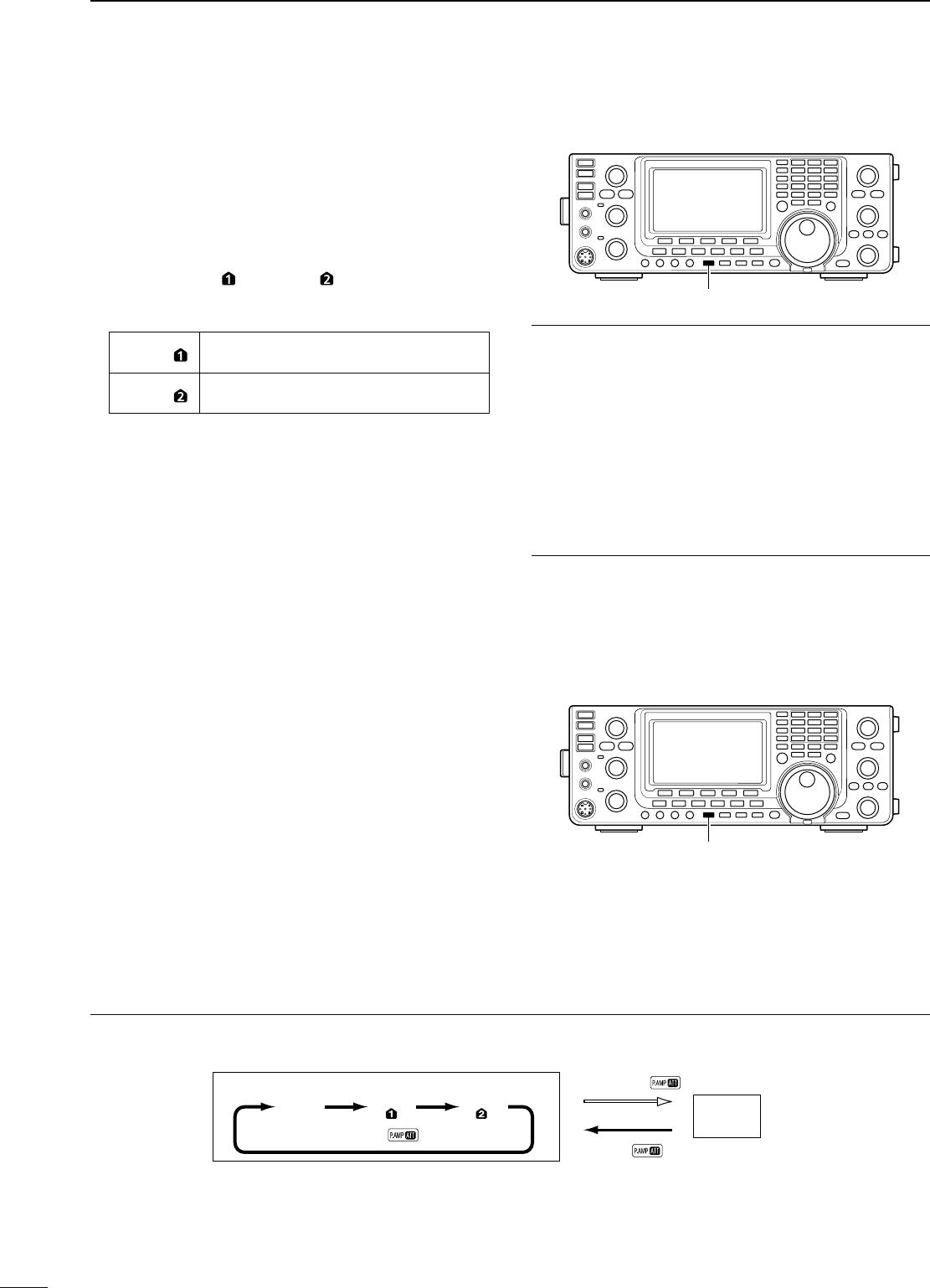
55
5FUNCTIONS FOR RECEIVE
N0REAMPLIlER
The preamplifier amplifies weak signals in the receiver
front end, to improve the S/N ratio and sensitivity.
Turn this function ON when receiving weak signals.
±0USH;0!-0s!44=ONEORMORETIMESTOSETTHE
preamp OFF, preamp 1 ON or preamp 2 ON.
s%ITHERh0!-0 ” or “P. AMP ” is displayed when the
preamp 1 or preamp 2 is ON.
s.OINDICATORISDISPLAYEDWHENTHEPREAMPIS/&&
P. AMP Wide dynamic range preamplifier. It is
most effective for 1.8 to 21 MHz bands.
P. AMP High-gain preamplifier. It is most effective
for 24 to 50 MHz bands.
N!TTENUATOR
The attenuator prevents a desired signal from being
distorted when very strong signals are near the sig-
nal’s frequency, or when very strong electromagnetic
fields, such as from broadcast stations are near your
location.
These can both be independently set for each band.
±(OLDDOWN;0!-0s!44=FORSECONDTOTURN/.
the Attenuator.
sh!44vAPPEARSWHENTHE!TTENUATORIS/.
±0USH;0!-0s!44=MOMENTARILYTOTURN/&&IT
About the “P.AMP2” preamplifier
The preamp 2 is a high gain receive amplifier. When
it is used in the presence of strong electromagnetic
fields, distortion sometimes results. In such cases, use
either the “P.AMP 1” or “P.AMP OFF” setting.
Preamp 2 is most effective when:
s5SEDONBANDSABOVE-(ZANDWHENSIGNALSARE
weak.
s2ECEIVESENSITIVITYISINSUFlCIENTWHENUSINGLOWGAIN
antennas, or while using a narrow band antenna.
!BOUTTHE0REAMPLIlERAND!TTENUATORSWITCHINGPROCEDURE
The Preamplifier and Attenuator are switched with [P.AMP/ATT], as shown below.
Hold down
Push
Push
ATT ON
P.AMP
OFF
P.AMP P.AMP
[PTT]
[PTT]
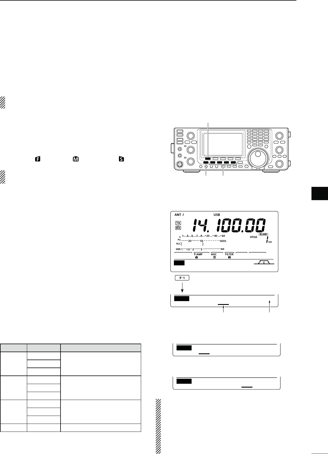
56
5
FUNCTIONS FOR RECEIVE
1
2
3
4
5
6
7
8
9
10
11
12
13
14
15
16
17
18
19
20
21
N!'#FUNCTION
The AGC (Auto Gain Control) controls receiver gain to
produce a constant audio output level, even when the
received signal strength varies greatly. The transceiver
has three pre-set AGC time constants; fast, mid, and
slow for SSB, CW, RTTY and AM modes.
In the FM mode, the AGC time constant is fixed to
“FAST” (0.1 second).
D!'#SPEEDSELECTION
q Select either the SSB, CW, RTTY or AM mode.
(p. 31)
w Push [MENU] to display the “M1” screen (Menu 1),
then push [AGC](F-1) one or more times to select
AGC fast ( ), AGC mid ( ) or AGC slow ( ).
“AGC OFF” appears when the selected AGC
speed’s time constant is set to OFF.
D3ETTINGTHE!'#TIMECONSTANT
q Select either the SSB, CW, RTTY or AM mode.
(p. 31)
w Push [MENU] to display the “M1” screen (Menu 1),
then hold down [AGC](F-1) for 1 second to display
the “AGC” screen.
e Push either [FAST](F-2), [MID](F-3) or [SLOW](F-4)
to select the desired AGC speed to be set.
s
An underline appears below the time constant display.
r Rotate [DIAL] to set the desired time constant.
s!'#TIMECONSTANTCANBESETTOBETWEENTO
seconds (depending on the mode) or turned OFF.
s(OLDDOWN;&!34=&, [MID](F-3) or [SLOW](F-4) for
1 second to reset to the default setting for the selected
time constant.
t Select another mode (except for FM), then repeat
steps e and r, if desired.
y Push [MENU] to save, and exit the “AGC” screen.
s3ELECTABLE!'#TIMECONSTANT (unit: seconds)
-ODE $EFAULT 3ELECTABLE!'#TIMECONSTANT
SSB
0.3 (FAST)
OFF, 0.1, 0.2, 0.3, 0.5, 0.8, 1.2,
1.6
, 2.0, 2.5, 3.0, 4.0, 5.0, 6.0
2.0 (MID)
6.0 (SLOW)
CW/RTTY
0.1 (FAST)
OFF, 0.1, 0.2, 0.3, 0.5, 0.8, 1.2,
1.6
, 2.0, 2.5, 3.0, 4.0, 5.0, 6.0
0.5 (MID)
1.2 (SLOW)
AM
3.0 (FAST)
OFF, 0.3, 0.5, 0.8, 1.2, 1.6
, 2.0,
2.5, 3.0, 4.0, 5.0, 6.0, 7.0, 8.0
5.0 (MID)
7.0 (SLOW)
FM 0.1 (FAST) Fixed
s7HEN!'#FASTISSELECTED
0.3s 2.0s 6.0s
FAST MID SLOW SSB
AGC
s7HEN!'#SLOWISSELECTED
0.3s 2.0s 6.0s
FAST MID SLOW SSB
AGC
[AGC]
[MENU] Mode keys
Appears under the selected AGC
speed’s time constant display.
Selected mode
AGC TBW SCP
M1
0.3s 2.0s 6.0s
FAST MID SLOW SSB
AGC
Hold down
For your information
When you are receiving a weak signal, and a strong
signal is momentarily received, the AGC function
quickly reduces the receiver gain. When that sig-
nal disappears, the transceiver may not receive
the weak signal because of the AGC action. In that
case, hold down [AGC](F-1) for 1 second, and ro-
tate [DIAL] to set the time constant to OFF.
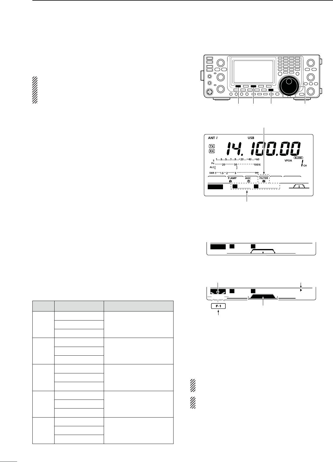
57
5FUNCTIONS FOR RECEIVE
N)&lLTERSELECTION
The transceiver has 3 passband width IF filters for
each mode.
The filter selection is automatically memorized in
each mode.
The PBT shift frequencies are automatically memo-
rized in each filter.
D)&lLTERSELECTION
q Select the desired mode.
w Push [FILTER] one or more times to select IF filter
1, 2 or 3.
s4HESELECTEDPASSBANDWIDTHANDlLTERNUMBERISDIS-
played on the LCD.
D&ILTERPASSBANDWIDTHSETTING
(-ODE33"#72449!-
q Hold down [FILTER] for 1 second to display the “FIL”
screen (Filter) to set the filter passband width.
w Select either the SSB, CW, RTTY or AM mode.
s0ASSBANDWIDTHSFORTHE&-MODEISlXEDANDCANNOT
be set.
e Push [FILTER] one or more times to select IF filter
1, 2 or 3.
r Push [BW](F-1), then rotate [DIAL] to adjust the de-
sired passband width.
Then push
[BW](F-1)
to set it.
s7HILE HOLDING DOWN ;"7=& ROTATING ;$)!,= ALSO
adjusts the passband width. After adjustment, release
[BW](F-1) to set it.
s(OLDDOWN;&=FORSECONDTORESETTOTHEDEFAULTSET-
ting, if desired.
t Repeat steps w to r if desired.
y Push [MENU] to save, and exit the “FIL” screen.
-ODE )&lLTER !DJUSTABLERANGESTEPS
SSB
FILTER1 (3.0 kHz)
50 to 500 Hz (50 Hz)
600 to 3600 Hz (100 Hz)
FILTER2 (2.4 kHz)
FILTER3 (1.8 kHz)
SSB-D
CW
FILTER1 (1.2 kHz)
50 to 500 Hz (50 Hz)
600 to 3600 Hz (100 Hz)
FILTER2 (500 Hz)
FILTER3 (250 Hz)
RTTY
FILTER1 (2.4 kHz)
50 to 500 Hz (50 Hz)
600 to 2700 Hz (100 Hz)
FILTER2 (500 Hz)
FILTER3 (250 Hz)
AM
AM-D
FILTER1 (9.0 kHz)
200 Hz to 10 kHz (200 Hz)
FILTER2 (6.0 kHz)
FILTER3 (3.0 kHz)
FM
FM-D
FILTER1 (15 kHz)
Fixed
FILTER2 (10 kHz)
FILTER3 (7.0 kHz)
Push [BW](F-1), then rotate [DIAL] to adjust the
passband width. Then push [BW](F-1),
BW
SSB-2 2.4K
SHARP
FIL S
0
B
2.4K
BW
SSB-2 2.4K
SHARP
FIL S
0
B
2.4K
s“FIL” SCREENDISPLAY
s7HILEADJUSTINGTHEPASSBANDWIDTH
AppearsBlinks
Reverses
Shows the selected filter and passband width.
The PBT shift frequencies are cleared when the
passband width is changed.
This “FIL” screen (Filter) graphically displays the
PBT shift frequencies and passband width.
[FILTER][BW] [F-3] [DIAL]
The selected filter width is displayed
when [FILTER] is pushed.
Filter selection
AGC TBW SCP
M1 S
0
B
2.4K
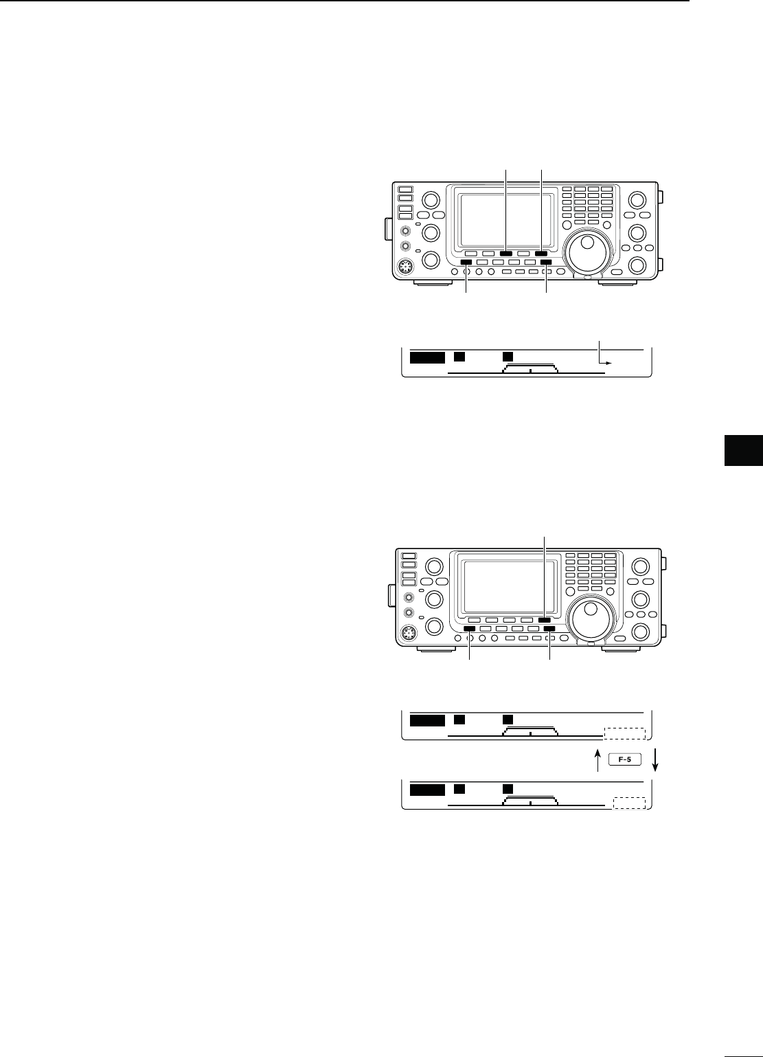
58
5
FUNCTIONS FOR RECEIVE
1
2
3
4
5
6
7
8
9
10
11
12
13
14
15
16
17
18
19
20
21
DST)&lLTERSELECTION
-ODE33"#72449!-
The IC-7410 has a 15 kHz filter passband width at the
1st IF frequency. The 1st IF filters reduce interference
from strong nearby signals.
If the optional FL-430 1ST IF FILTER (6 kHz) is installed,
a 6 kHz filter width can be used
. Or, if the FL-431 1ST
IF FILTER (3 kHz) is installed, a 3 kHz
filter width can be
used
.
q Hold down [FILTER] for 1 second to display the
“FIL” screen (Filter).
w Select SSB, CW, RTTY or AM mode.
s4HEPASSBANDWIDTHFORTHE&-MODEISlXED
e Hold down [F-5] for 1 second to select the desired
filter width from 15 kHz, 6 kHz and 3 kHz.
s(OLDDOWN;&=FORSECONDTORESETTOTHEDEFAULTlLTER
setting, if desired. (The filter passband width setting is
also reset to the default setting.)
r Push [MENU] to save, and exit the “FIL” screen.
D)&$30lLTERSHAPE
-ODE33"#7
A soft or sharp type of DSP filter shape for both SSB
and CW can be independently selected.
q Hold down [FILTER] for 1 second to display the “FIL”
screen (Filter).
w Select the SSB or CW mode.
e Push [F-5]
once or twice
to select either the soft or
sharp filter shape.
r Push [MENU] to save, and exit the “FIL” screen.
[MENU] [FILTER]
[F-5][F-3]
15 kHz is selected.
BW
SSB-2 2.4K
R:15K
SHARP
FIL S
0
B
2.4K
[MENU] [FILTER]
[F-5]
BW
SSB-2 2.4K
SHARP
FIL S
0
B
2.4K
BW
SSB-2 2.4K
SOFT
FIL S
0
B
2.4K
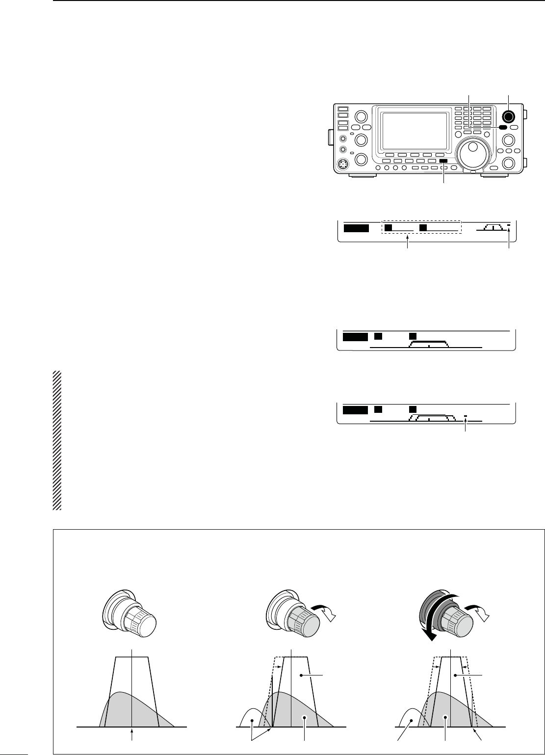
59
5FUNCTIONS FOR RECEIVE
N4WIN0"4OPERATION
-ODE33"#72449!-
To reject interference, PBT (Passband Tuning) elec-
tronically narrows the IF passband width by shifting the
IF frequency slightly outside of the IF filter passband.
The IC-7410 uses DSP for the PBT function. Moving
both [TWIN-PBT] controls shift the IF passband cen-
ter frequency both above and below the received fre-
quency.
± The LCD graphically shows the passband width and
frequency shift.
± Hold down [FILTER] for 1 second to display the “FIL”
screen (Filter). Current passband width and fre-
quency shift are displayed in the “FIL” screen.
± Hold down [PBT-CLR] for 1 second to set the IF
frequency to the center position.
s4HEhDOTvDISAPPEARS
The variable range depends on the passband width
and mode. The edge of the variable range is half of the
passband width. The PBT is adjustable in 25 Hz steps
in the SSB/CW/RTTY modes, and 100 Hz in the AM
mode.
s
The [TWIN-PBT] controls should normally be set
to the center positions when there is no interfer-
ence. The PBT setting should be cleared.
s7HEN THE 0"4 IS USED THE AUDIO TONE MAY
change.
s4HECONTROLSDONOTFUNCTIONINTHE&-MODE
s7HILEROTATING THE ;47).0"4= CONTROLS NOISE
may occur. This comes from the DSP unit and
does not indicate an equipment malfunction.
s
Pushing [PBT-CLR] displays the filter passband
width and shift value for 2 seconds on the function
display.
0"4/0%2!4)/.%8!-0,%
DUPAGC COMP TBW SCP
M1 S
+ 25
B
2.3K
Passband width and shift
value are displayed while
[TWIN PBT] is used.
Appears when pass-
band is shifted.
BW
SSB-2 2.4K
SHARP
FIL S
0
B
2.4K
BW
SSB-2 2.4K
SHARP
FIL S
+200
B
2.0K
sh&),v SCREEN&ILTERDISPLAY
s7HILEADJUSTINGTHE0"4SETTING
Appears when the passband is shifted.
Shows the selected filter and passband width.
Both controls in the center
positions (or hold down
[PBT-CLR] for 1 second.)
Cutting the lower
passband edge
Cutting both lower and
higher passband edges
PBT2
PBT1
PBT2
PBT1
PBT2
PBT1
IF center frequency Interference Desired signal
Passband
Interference InterferenceDesired signal
Passband
[TWIN-PBT][PBT-CLR]
[FILTER]
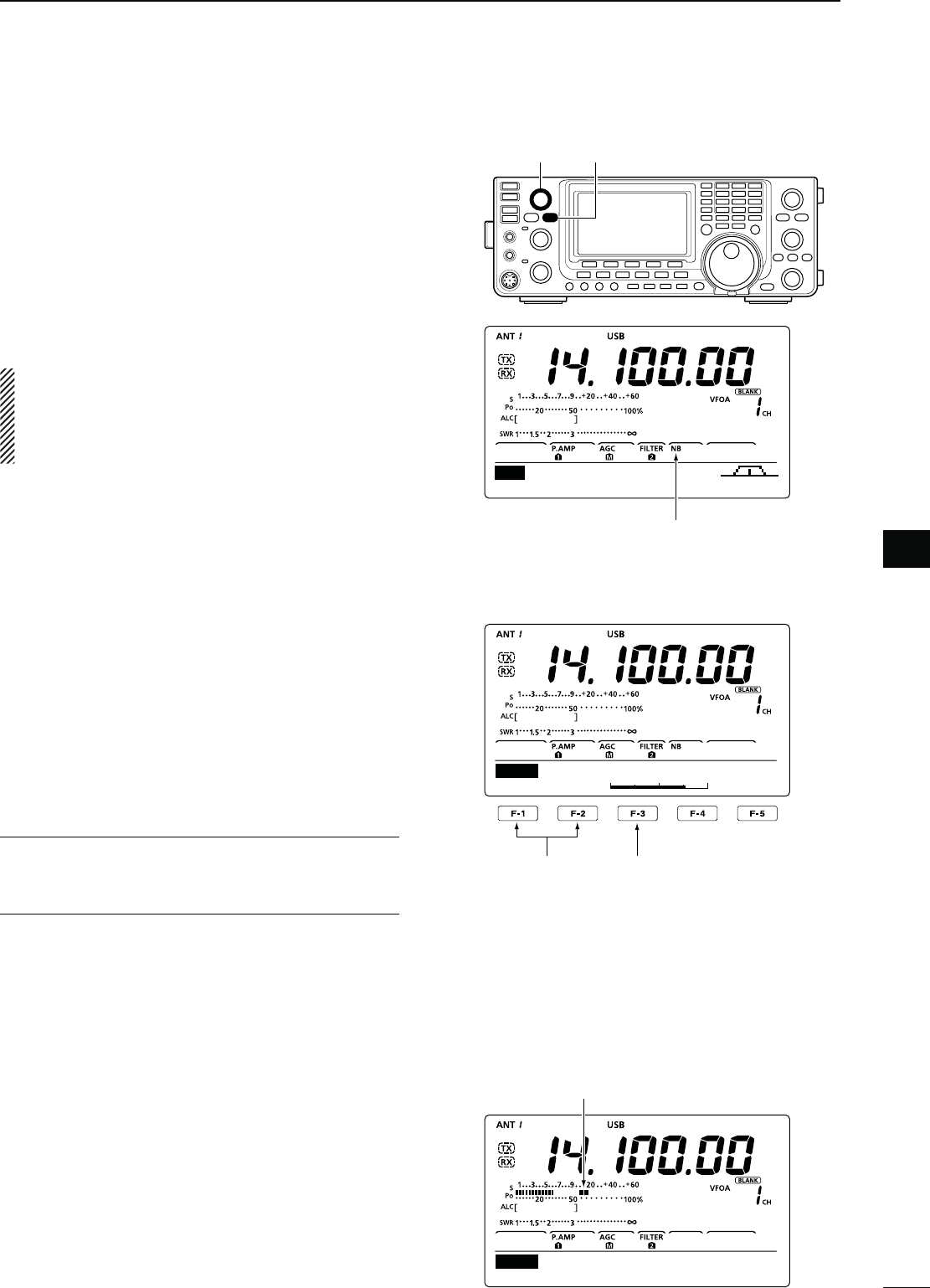
60
5
FUNCTIONS FOR RECEIVE
1
2
3
4
5
6
7
8
9
10
11
12
13
14
15
16
17
18
19
20
21
N.OISE"LANKER
-ODE33"#72449!-
The Noise Blanker eliminates pulse-type noise such
as noise from car ignitions.
q
Push [NB] to turn ON the Noise Blanker function.
sh."vAPPEARS
w Rotate the [NB] control to adjust the Noise Blanker
threshold level.
e Push [NB] again to turn OFF the function.
sh."vDISAPPEARS
When using the Noise Blanker function, received
signals may be distorted if they are excessively
strong or when used for noise other than pulses. In
this case, set the Noise Blanker threshold level to a
shallow position, or turn OFF the function.
N-ETER0EAK(OLDFUNCTION
When the “Meter Peak Hold” item is set to ON in the
Set mode, the peak level of a received signal strength
or the output power is displayed for approximately 0.5
seconds. (p. 86).
D."3ETMODE
To deal with various types of noise, the attenuation
level and noise blanking duration can be set in the NB
Set mode.
q Hold down [NB] for 1 second to display the “NB”
screen (Noise Blanker).
w Push [Y](F-1) or [Z](F-2) to select the desired
item.
e Rotate [DIAL] to select the desired option.
s(OLDDOWN;&=FORSECONDTORESETTOTHEDEFAULTSET-
ting, if desired.
r Push [NB] to save and return to the previous
screen.
."$EPTH1. $EFAULT
Set the noise attenuation level to between 1 and 10.
."7IDTH2. $EFAULT
Set the blanking duration to between 1 and 100.
[NB][NB] control
AGC TBW SCP
M1
Appears
Select the item
Select a default
setting
1
8
NB
NB Depth
Appears for 0.5 seconds.
Ù 10 ÚON
SET Meter Peak Hold
61
5FUNCTIONS FOR RECEIVE
N.OISE2EDUCTION
The Noise Reduction function reduces random noise
components and enhances audio signals which are
buried in noise. The received signals are converted
to digital signals and then the audio signals are sepa-
rated from the noise.
q
Push [NR] to turn ON the Noise Reduction function.
sh.2vAPPEARS
w Rotate the [NR] control to adjust the noise reduc-
tion level.
e Push [NR] again to turn OFF the function.
sh.2vDISAPPEARS
A large rotation of the [NR] control results in audio
signal masking or distortion. Set the [NR] control for
maximum readability.
N.OTCHFUNCTION
-ODE !UTONOTCH 33"!-&-
-ANUALNOTCH33"#72449!-
This transceiver has Auto and Manual Notch functions.
The Auto Notch function uses DSP to automatically at-
tenuate beat tones, tuning signals, etc., even if their
frequencies are changing. The Manual Notch function
allows you to manually attenuate a frequency via the
[NOTCH] control.
± In the SSB or AM mode, push [NOTCH] to toggle
the Notch function between auto, manual and
OFF.
s%ITHERTHE!UTOOR-ANUAL.OTCHFUNCTIONCANBEDIS-
abled in the Set mode. (p. 88)
± In the CW or RTTY mode, push [NOTCH] to turn
the Manual Notch function ON or OFF.
± In the FM mode, push [NOTCH] to turn the Auto
Notch function ON or OFF.
sh-.&vAPPEARSWHENTHE-ANUAL.OTCHFUNCTIONIS/.
sh!.&vAPPEARSWHENTHE!UTO.OTCHFUNCTIONIS/.
s.OINDICATORAPPEARSWHENTHENOTCHlLTERIS/&&
s7HENTHE -ANUAL.OTCH FUNCTIONIS /.HOLD DOWN
[NOTCH] for 1 second to select the wide, mid, or nar-
row manual notch filter width.
N$IAL,OCKFUNCTION
The Dial Lock function prevents frequency changes by
accidental movement of [DIAL] by electronically lock-
ing it.
± Push [LOCK] to turn the Dial Lock function ON or
OFF.
sh ” appears when the Dial Lock function is ON.
[NR] control[NR]
[LOCK]
While tuning the manual notch filter, noise may
be heard. This comes from the DSP unit and
does not indicate an equipment malfunction.
.OISEREDUCTION/..OISEREDUCTION/&&
Desired
signal (CW)
Noise components
[NOTCH] control [NOTCH]
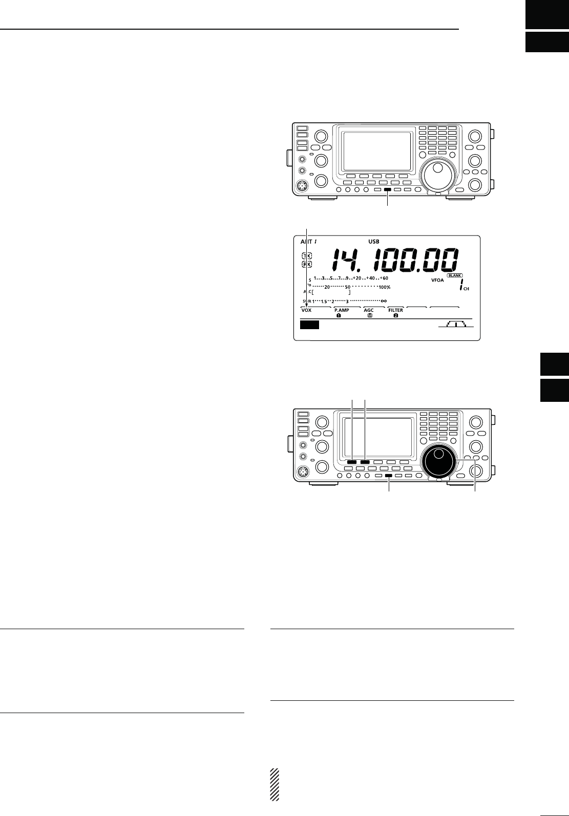
6
62
1
2
3
4
6
7
8
9
10
11
12
13
14
15
16
17
18
19
20
21
FUNCTIONS FOR TRANSMIT
5
N6/8FUNCTION
-ODE33"!-&-
The VOX (Voice-Operated Transmission) function
switches the transceiver between transmit and receive
with your voice. This function provides hands-free op-
eration.
D5SINGTHE6/8FUNCTION
q Select a phone mode (SSB, AM, FM). (p. 31)
w Push [VOX/BK-IN] to turn the VOX function ON or
OFF.
sh6/8vAPPEARSWHENTHE6/8FUNCTIONIS/.
D!DJUSTINGTHE6/8FUNCTION
q Select a phone mode (SSB, AM, FM). (p. 31)
w Hold down [VOX/BK-IN] for 1 second to display the
“VOX” screen.
e Push
[Y](F-1) or [Z](F-2)
to select the VOX Gain
item.
r While speaking into the microphone, rotate [DIAL]
to the point where the transceiver is continuously
transmitting.
t If the received audio from the speaker causes the
VOX circuit to switch to transmit, push [Y] (F-1) or
[Z] (F-2) to select the Anti-VOX item. Then adjust
the anti-VOX setting to the point where received
audio does not activate the VOX.
y Adjust the VOX delay for a convenient interval be-
fore returning to receive after you stop speaking.
u
Set the VOX voice delay, if desired.
i Push [MENU] to return to the previous menu.
VOX Gain 1. $EFAULT
!DJUSTTHE6/8GAINTOBETWEENANDIN
steps.
Higher values make the VOX function more sensitive
to your voice.
Anti-VOX 2. $EFAULT
!DJUSTTHE!.4)6/8GAINTOBETWEENAND
INSTEPS
Higher values make the VOX function less sensitive to
the received audio from a speaker or headphones.
VOX Delay 3. $EFAULTS
Set the VOX delay to between 0.0 and 2.0 seconds,
for normal pauses in speech before returning to re-
ceive.
6/86OICE$ELAY4. $EFAULT/&&
Set the VOX voice delay to prevent clipping of the
first few syllables of a transmission when switching to
transmit.
OFF, Short, Mid and Long settings can be set.
When using the VOX voice delay, turn OFF the TX
Monitor function to prevent transmitted audio from
being echoed.
[VOX/BK-IN]
Appears
AGC TBW SCP
M1
[VOX/BK-IN] [DIAL]
[][]
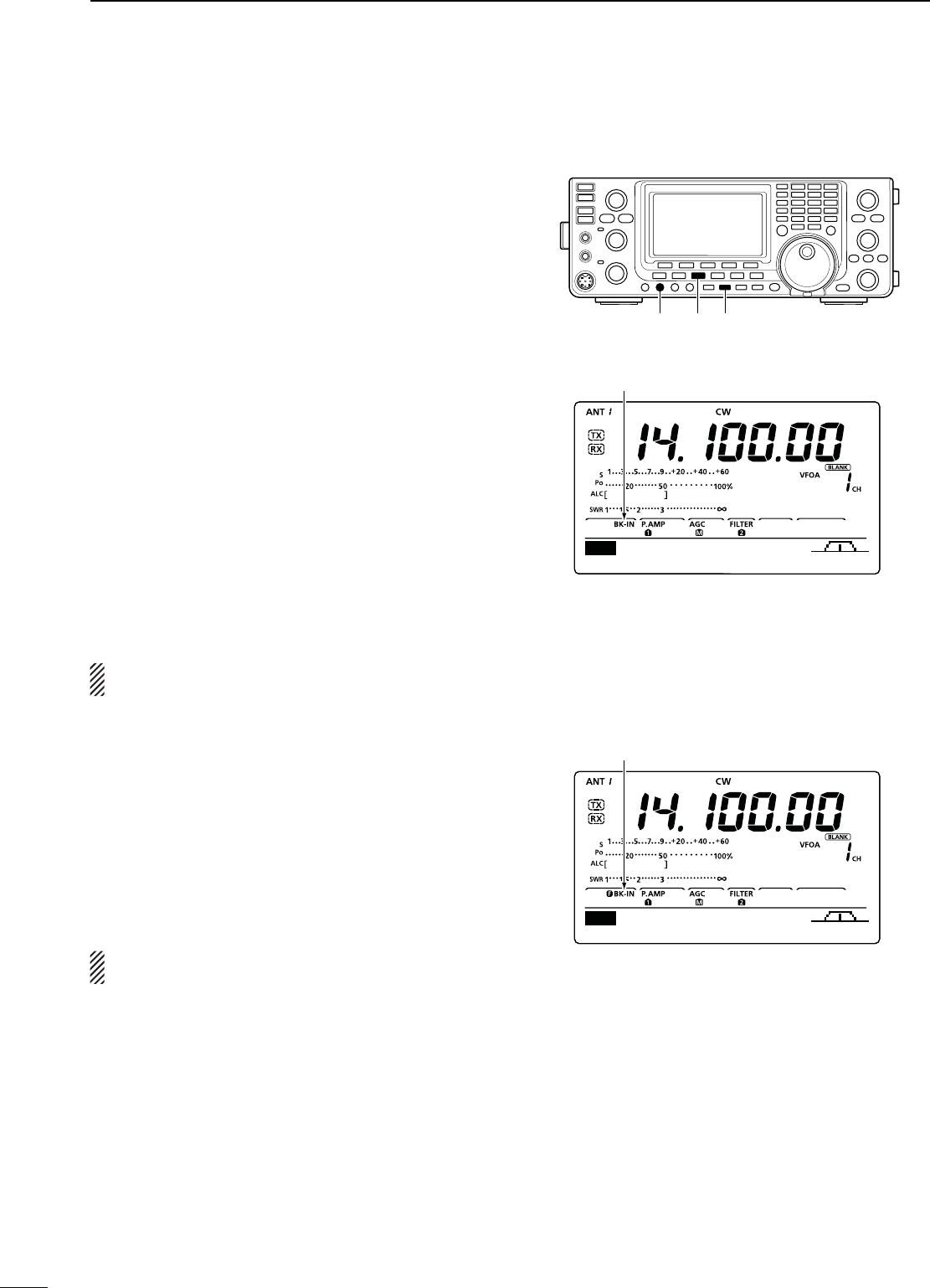
63
6FUNCTIONS FOR TRANSMIT
N"REAKINFUNCTION
-ODE#7
The Break-in function is used in the CW mode to auto-
matically toggle the transceiver between transmit and
receive when keying. The IC-7410 is capable of Full
Break-in or Semi Break-in.
D3EMI"REAKINOPERATION
During Semi Break-in operation, the transceiver imme-
diately transmits when you key down, then returns to
receive after a pre-set delay time has passed after you
stop keying.
q Push [CW] to select the CW or CW-R mode.
w Push [VOX/BK-IN] one or more times to turn ON
the Semi Break-in function.
sh"+).vAPPEARS
e Rotate the [BK-IN DELAY] control to adjust the
break-in delay time (the delay from transmit to re-
ceive).
When using a paddle, rotate the [KEY SPEED] con-
trol to adjust the keying speed.
D&ULL"REAKINOPERATION
During Full Break-in operation, the transceiver trans-
mits when you key down, then immediately returns to
receive when you release.
q Push [CW] to select the CW or CW-R mode.
w Push [VOX/BK-IN] one or more times to turn ON
the Full Break-in function.
shFBK-IN” appears.
When using a paddle, rotate the [KEY SPEED] con-
trol to adjust the keying speed.
Appears
Appears
AGC 1/4 KEY SCP
M1
[VOX/BK-IN][BK-IN DELAY] [CW]
AGC 1/4 KEY SCP
M1
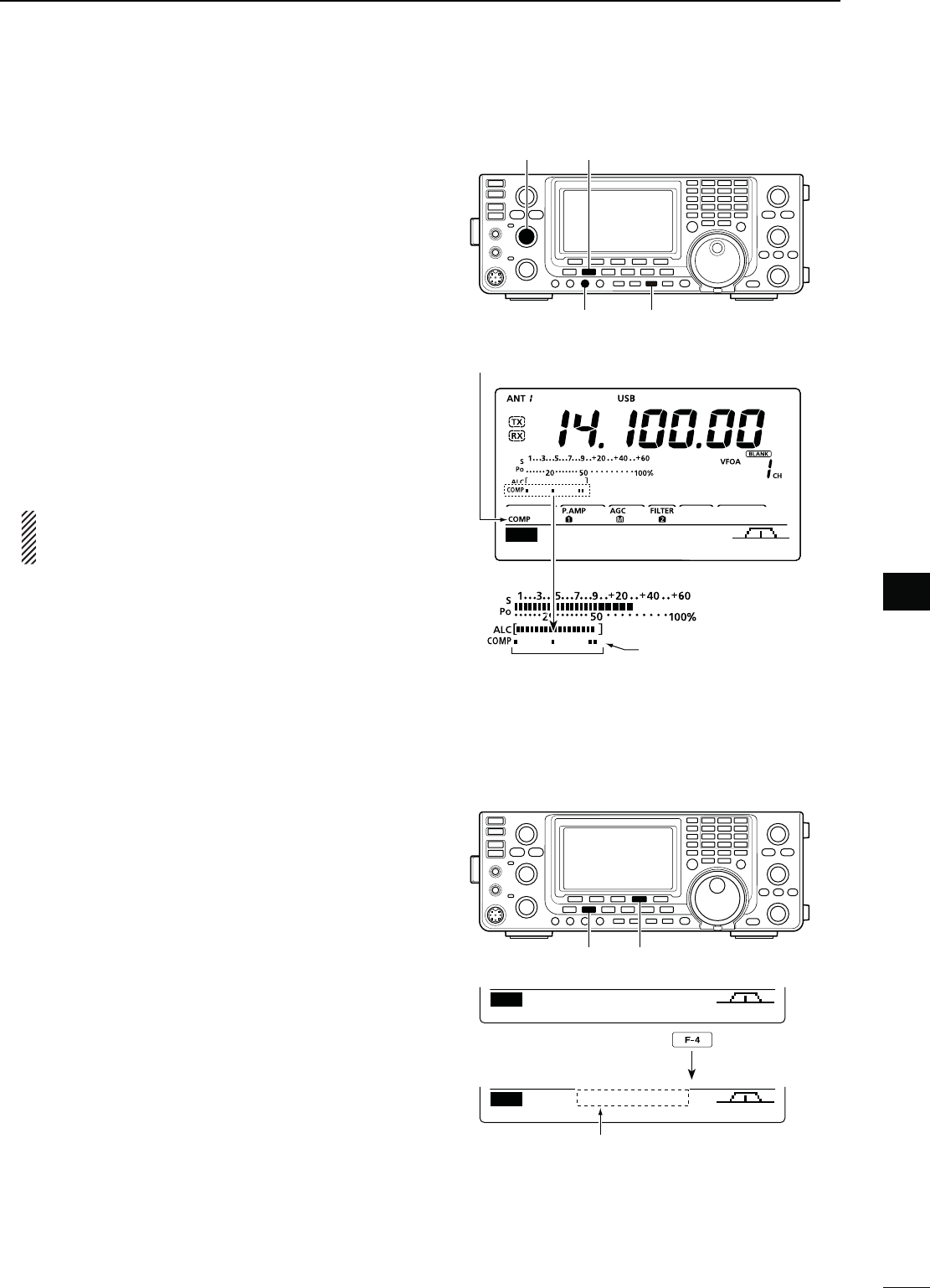
64
6
FUNCTIONS FOR TRANSMIT
1
2
3
4
5
6
7
8
9
10
11
12
13
14
15
16
17
18
19
20
21
N3PEECH#OMPRESSOR
-ODE33"
The Speech Compressor function increases average
RF output power, improving signal strength and read-
ability.
q Push [SSB] to select the USB or LSB mode.
w Rotate the [MIC] control to adjust the microphone
gain so the ALC meter reads within the ALC zone,
whether or not you speak softly or loudly.
e P
ush [COMP] to turn ON the Speech Compressor
function.
sh#/-0vAPPEARS
r While speaking into the microphone at your normal
voice level, rotate the [COMP] control to adjust the
compressor level so the COMP meter reads within
the COMP zone.
s(OLDDOWN;&=FORSECONDTORESETTOTHEDEFAULTSET-
ting, if desired.
When the COMP meter peaks above the COMP
level zone, your transmitted voice may be dis-
torted.
N
4RANSMITlLTERWIDTHSELECTION
-ODE33"
The transmit filter width for the SSB mode can be set
to Wide, Mid or Narrow.
q Push [SSB] to select the USB or LSB mode.
w
P
ush [MENU] to display the “M1” screen (Menu
1), then hold down [TBW](F-4) for 1 second, one
or more times, to select a Wide, Mid or Narrow
transmission passband width.
s0USH;4"7=&MOMENTARILYTODISPLAYTHESELECTED
TX filter width for approximately 1 second.
s4HEFOLLOWINGlLTERSARESPECIlEDASTHEDEFAULTS%ACH
of the filter widths can be set in the Tone Control Set
mode. (pp. 90, 91)
- WIDE : 100 Hz to 2900 Hz
- MID : 300 Hz to 2700 Hz
- NAR : 500 Hz to 2500 Hz
Hold down
The selected transmit filter width is
displayed for approximately 1 second.
[SSB]
[COMP][COMP] control
[MIC] control
Appears
COMP level zone
COMP meter
AGC TBW SCP
M1
[SSB] [TBW]
AGC TBW SCP
M1
AGC TBW SCP
M1 TBW WIDE
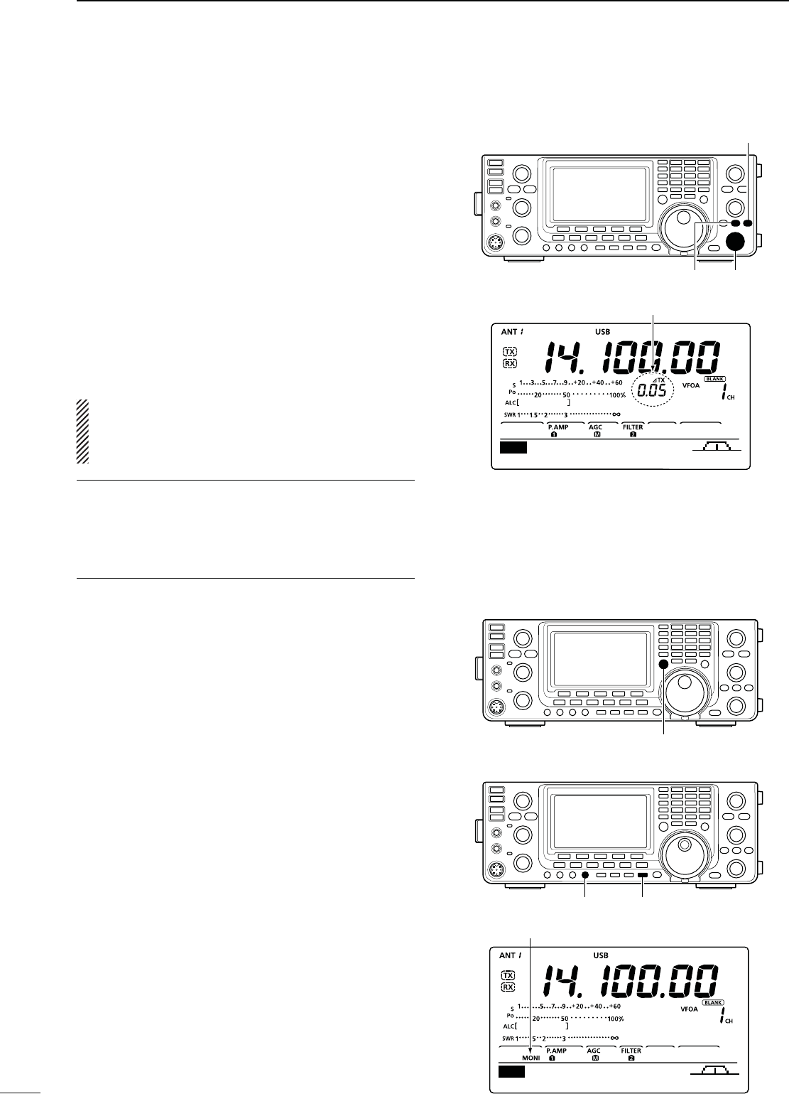
65
6FUNCTIONS FOR TRANSMIT
N ∂48FUNCTION
The ∂TX function shifts the transmit frequency up to
±9.99 kHz in 10 Hz steps* without changing the re-
ceive frequency.
* The [RIT/∂TX] control tunes in 1 Hz steps when the operat-
ing frequency readout is set to the 1 Hz step option.
q Push [∂TX] to turn ON the ∂TX function.
sh∂TX” and the frequency shift appear.
w Rotate the [RIT/∂TX] control.
e To reset the ∂TX frequency, hold down [CLEAR]
for 1 second.
s0USH;#,%!2=MOMENTARILYTORESETTHE∂TX frequency
when the “Quick RIT Clear” item is set to “ON” in the
Set mode. (p. 88)
r To cancel the ∂TX function, push [∂TX] again.
sh∂TX” and the frequency shift disappear.
When the RIT and ∂TX functions are ON at the
same time, the [RIT/∂TX] control shifts both the
transmit and receive frequencies from the displayed
frequency at the same time.
&ORYOURCONVENIENCE#ALCULATEFUNCTION
The frequency shift of the ∂TX function can be added
to or subtracted from the displayed frequency.
± While displaying the ∂TX frequency shift, hold
down [∂TX] for 1 second.
D ∂48-ONITORFUNCTION
When the ∂TX function is ON, holding down [XFC]
allows you to directly monitor the transmit frequency
(including the ∂TX frequency offset).
N-ONITORFUNCTION
The Monitor function allows you to listen to your trans-
mit IF signals in any mode. Use this to check voice
characteristics while adjusting SSB transmit param-
eters. (pp. 90, 91)
The CW sidetone functions regardless of the [MONI-
TOR] setting.
q Push [MONITOR] to turn ON the Monitor function.
sh-/.)vAPPEARS
w Rotate the [MONI GAIN] control to adjust the moni-
tor level.
s&or the clearest audio output, adjust while holding
down [PTT] and speaking into the microphone.
e Push [MONITOR] again to turn OFF the function.
sh-/.)vDISAPPEARS
[∂TX] [RIT/∂TX]
[CLEAR]
Appear
[XFC]
AGC TBW SCP
M1
[MONITOR][MONI GAIN]
AGC TBW SCP
M1
Appears
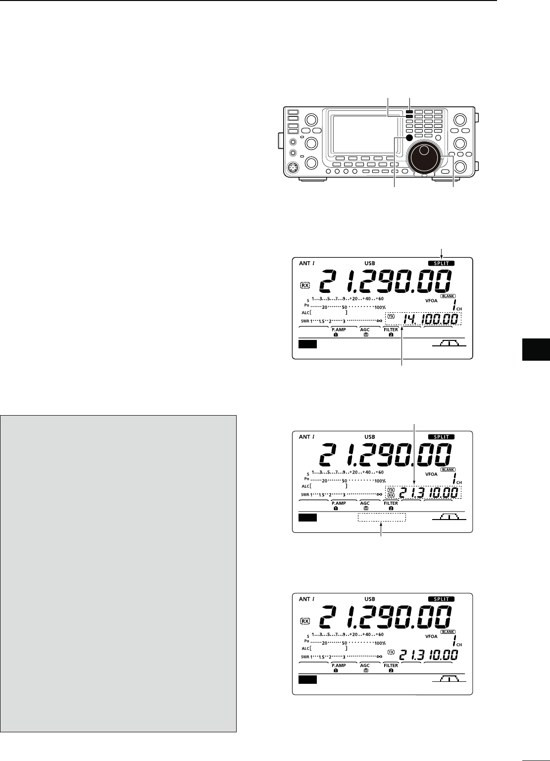
66
6
FUNCTIONS FOR TRANSMIT
1
2
3
4
5
6
7
8
9
10
11
12
13
14
15
16
17
18
19
20
21
N3PLITFREQUENCYOPERATION
Split frequency operation allows you to transmit and
receive on two different frequencies. Split frequency
operation is performed using frequencies in VFO A
and VFO B.
The following is an example of setting 21.290 MHz for
receiving and 21.310 MHz for transmitting.
q Set 21.290 MHz in VFO A.
w Push [SPLIT] to turn ON the Split operation.
s4HETRANSMIT6&/"FREQUENCYANDh30,)4vAPPEAR
e Hold down [A=B] for 1 second to equalize the trans-
mit (VFO B) frequency to the receive (VFO A) fre-
quency.
s4HEEQUALIZEDTRANSMIT6&/"FREQUENCYAPPEARS
s4HE1UICK3PLITFUNCTIONISMUCHMORECONVENIENTFOR
selecting the transmit frequency. See the next section
for details.
r While holding down [XFC], rotate [DIAL] to set the
transmit frequency to 21.310 MHz.
s4HETRANSMITFREQUENCYCANBEMONITOREDWHILEHOLDING
down [XFC].
t Now you can receive on 21.290 MHz and transmit
on 21.310 MHz.
To change the transmit and receive frequencies, push
[A/B] to exchange VFO A and VFO B.
CONVENIENT
s$IRECTFREQUENCYSHIFTINPUT
The frequency shift can be directly entered.
q Push [F-INP ENT].
w Enter the desired frequency shift with the digit
keys.
sK(ZTO-(ZCANBESET
s7HENYOUREQUIREAMINUSSHIFTDIRECTIONlRSTPUSH
;'%.%s=
e Push [SPLIT] to input the frequency shift to the
transmit frequency, and the Split function is turned
ON.
[Example]
To transmit on a 1 kHz higher frequency:
- Push [F-INP ENT], [1] then [SPLIT].
To transmit on a 3 kHz lower frequency:
0USH;&).0%.4=;'%.%s=;=THEN;30,)4=
s3PLIT,OCKFUNCTION
Accidentally releasing [XFC] while rotating [DIAL]
changes the receive frequency. To prevent this, use
both the Split Lock and Dial Lock functions to change
only the transmit frequency. The Split Lock function
cancels the Dial Lock function while holding down
[XFC] during split frequency operation.
The Split Lock function is OFF by default, but can be
turned ON in the Set mode. (p. 86)
Appears
Shows transmit (VFO B) frequency
Shows transmit (VFO B) frequency
Shows frequency shift and direction
s7HILEHOLDINGDOWN;8&#=
s!FTERSETTINGUP
s!FTERPUSHING;30,)4=
[XFC] [DIAL]
[A/B] [SPLIT]
AGC TBW SCP
M1
+20.00k
AGC TBW SCP
M1
AGC TBW SCP
M1
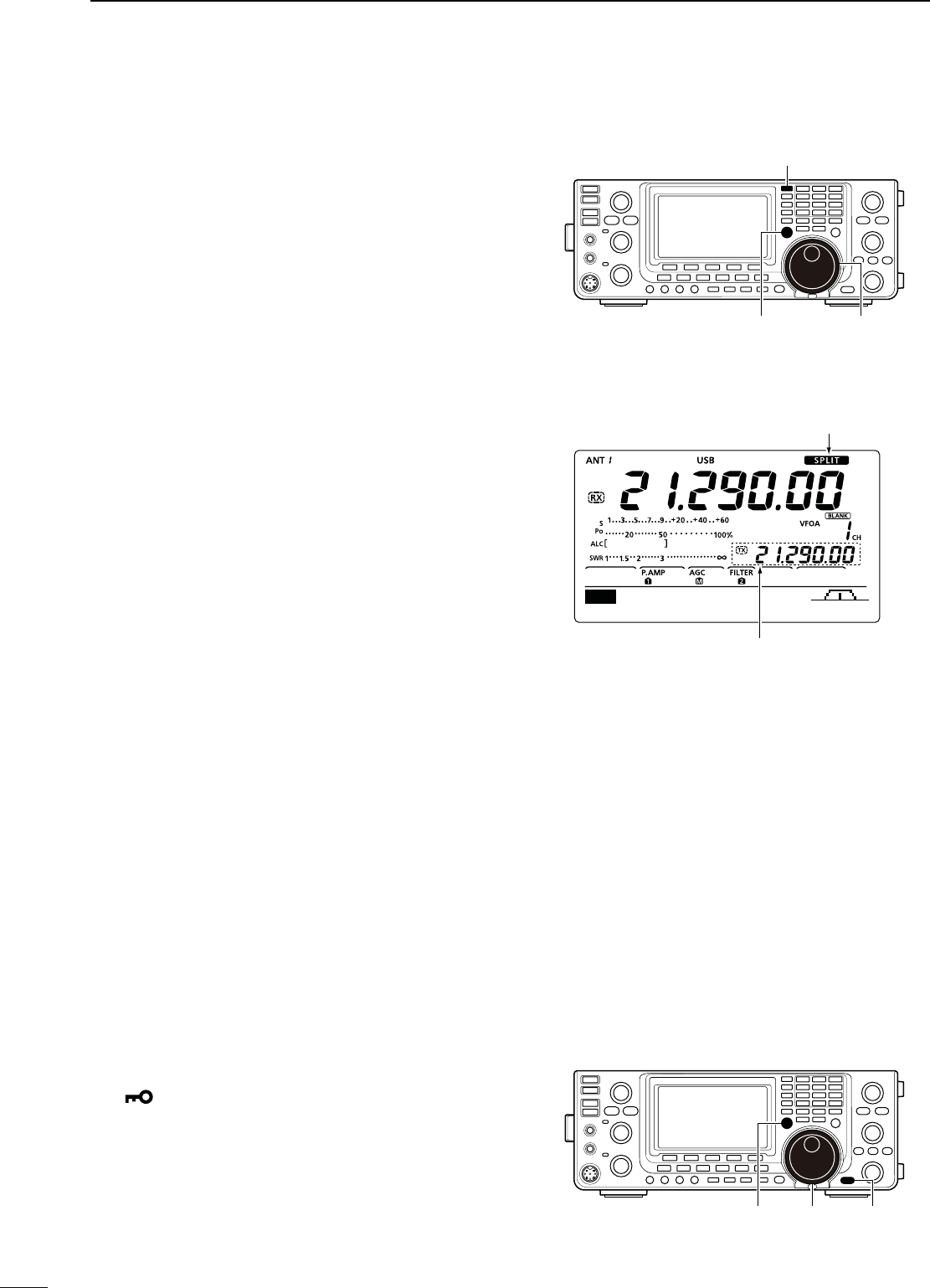
67
6FUNCTIONS FOR TRANSMIT
N1UICK3PLITFUNCTION
When you hold down [SPLIT] for 1 second, the Split
frequency operation is turned ON. The undisplayed
VFO is automatically changed according to the plus/
minus frequency shift programmed in the Set mode, or
equalized when 0 kHz (default setting) is programmed
as the split frequency shift. (p. 86)
The Quick Split function is ON by default. For your
convenience, it can be turned OFF in the Set mode.
(p. 86) In this case, holding down [SPLIT] does not
equalize the VFO A and VFO B frequencies.
q Suppose you are operating at 21.290 MHz (USB) in
VFO A.
w Hold down [SPLIT] for 1 second.
s3PLITFREQUENCYOPERATIONISTURNED/.
s4HETRANSMITFREQUENCY6&/"ISEQUALIZEDTOTHERE-
ceive frequency (VFO A).
s)NTHE&-MODETHETRANSMITFREQUENCY6&/"SHIFTS
from the receive frequency (VFO A) according to the
“FM SPLIT Offset HF” and “FM SPLIT Offset 50”
setting
in the Set mode.
s)NTHE&-MODETHE4ONE%NCODERFUNCTIONISAUTOMATI-
cally turned ON.
e While holding down [XFC], rotate [DIAL] to set the
transmit frequency.
s4HEFREQUENCYSHIFTISDISPLAYEDONTHEFUNCTIONDISPLAY
s9OUCANDIRECTLYSETTHEFREQUENCYSHIFT3EETHELEFT
page for details.
D3PLIT,OCKFUNCTION
The Split Lock function is convenient for changing only
the transmit frequency. When the Split Lock function is
not used, accidentally releasing [XFC] while rotating
[DIAL], changes the receive frequency.
The Split Lock function is OFF by default. Set the
“SPLIT LOCK” item to “ON” in the Set mode. (p. 86)
q While split frequency operation is ON, push [LOCK]
to turn ON the Split Lock function.
sh ” appears.
w While holding down [XFC], rotate [DIAL] to change
the transmit frequency.
s)F YOU ACCIDENTALLY RELEASE ;8&#= WHILE ROTATING THE
[DIAL], the receive frequency does NOT change.
Appears
Shows the equalized transmit (VFO B) frequency
s!FTERHOLDINGDOWN;30,)4=
[XFC] [DIAL]
[SPLIT]
AGC TBW SCP
M1
[XFC] [DIAL] [LOCK]
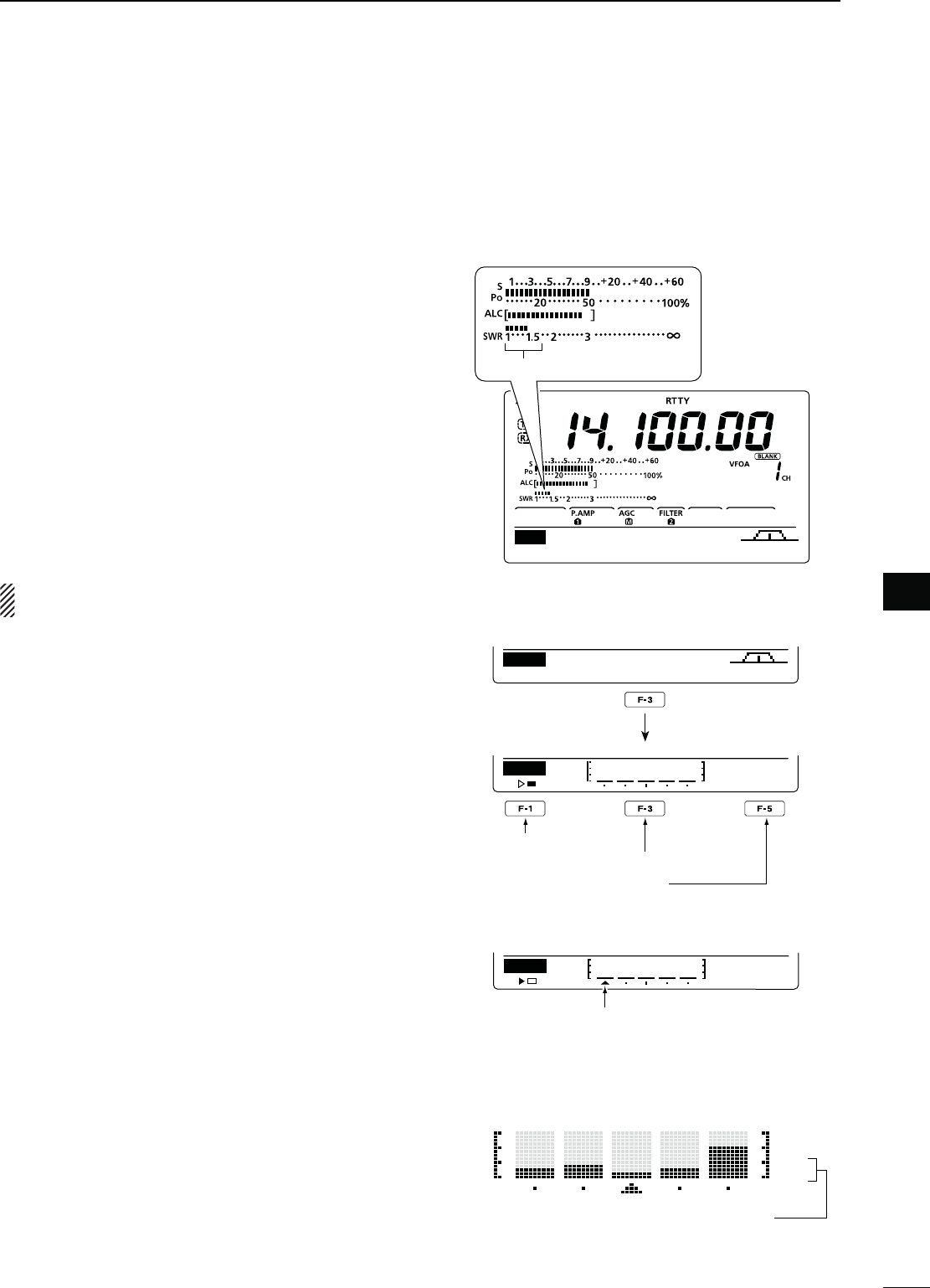
68
6
FUNCTIONS FOR TRANSMIT
1
2
3
4
5
6
7
8
9
10
11
12
13
14
15
16
17
18
19
20
21
N-EASURING372
The IC-7410 has a built-in circuit for measuring an-
tenna SWR— no external equipment or special adjust-
ments are necessary.
The IC-7410 can measure SWR two ways— spot mea-
surement and plot measurement.
D3POTMEASUREMENT
q Push [TUNER] once or twice to turn OFF the an-
tenna tuner.
w(OLDDOWN;!.4s-%4%2=FORSECONDONCEOR
twice, to select the SWR meter.
e Push [RTTY] to select the RTTY mode.
r Push [TRANSMIT] on the transceiver, or [PTT] on
the microphone to transmit.
t Rotate the [RF PWR] control clockwise past the 12
o’clock position for more than 30 W of output power
y Read the SWR on the SWR meter.
u Push [TRANSMIT] or release [PTT] to receive.
The built-in antenna tuner matches the transmitter
to the antenna only when the SWR is less than 3:1.
D0LOTMEASUREMENT
Plot measurement allows you to measure the SWR
over an entire band.
q
P
ush [MENU] to display the “M2” screen (Menu 2),
then push [SWR](F-3).
s4HE372GRAPHSCREENAPPEARS
w Rotate the [RF PWR] control clockwise past the 12
o’clock position for more than 30 W of output power
e Set the center frequency for the SWR to be mea-
sured.
r Hold down [F-5] for 1 second one or more times
to set the SWR measuring step to 10, 50, 100 or
500 kHz.
t Push [F-3] one or more times to select the number
of measuring steps to 3, 5, 7, 9, 11 or 13.
y Push [F-1] to start the measuring.
u Push [TRANSMIT] on the transceiver, or hold down
[PTT] on the microphone to transmit, to measure
the SWR.
s! FREQUENCY MARKER h∫,” appears below the SWR
graph.
i Push [TRANSMIT] again or release [PTT] to move
the frequency marker and frequency indication to
the next frequency to be measured.
o Repeat steps u and i to measure the SWR over
the entire frequency range.
!0 When the measured SWR is less than 1.5:1, the
antenna is well matched with the transceiver in the
measured frequency range.
MEMSCN SWR TCON VSC
M2
SWR
10k
STEP
Push
Start measuring
Select number of SWR measuring steps
Select SWR measuring step
s-EASURING (after pushing [F-1])
SWR
10k
STEP
A frequency marker appears and moves
after measurement.
When measurement points are set out-
side of the operatable frequency band,
the frequency marker blinks.
— 1.0:1
— 1.5:1
— 2.0:1
— 3.0:1
AGC 1⁄4 RTTY SCP
M1
The best match is in this range.
Typical display SWR varying between 1 and 2,
full scale up to SWR 4.0:1.
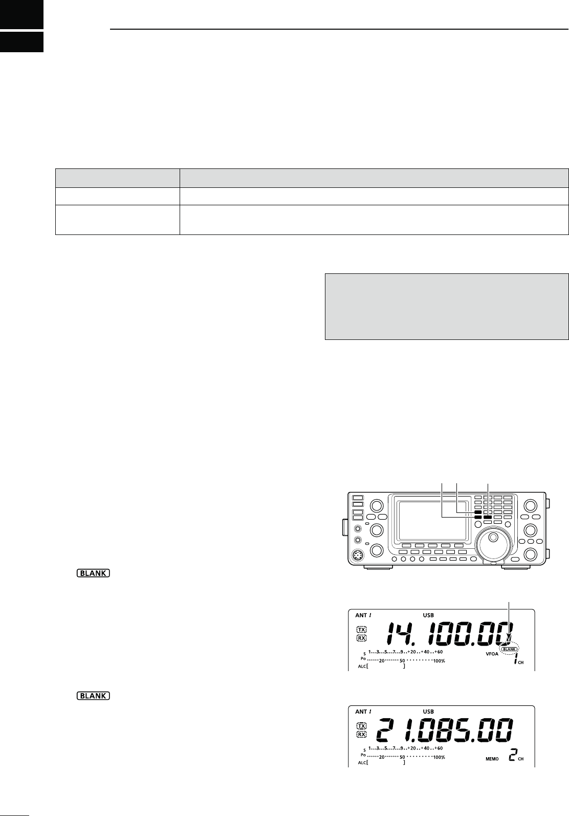
69
MEMORY OPERATION
7
N'ENERALDESCRIPTION
The transceiver has 101 Memory channels (99 regular,
and 2 scan edges). The Memory mode is very useful
to quickly change to often-used frequencies.
While in the memory mode, all 101 Memory channels
are tunable, which means the programmed frequency
can be tuned temporarily with [DIAL].
-EMORY#HANNELS $ESCRIPTIONS
1–99 Regular Memory channels with Split frequency capability.
P1, P2 Program Scan Edge Memory channels with only Simplex capability.
Stores the scan edge frequencies for the programmed scan.
D-EMORYCHANNELCONTENTS
The following information can be programmed into
Memory channels:
s/PERATINGFREQUENCYP
s/PERATINGMODEP
s)&lLTERNUMBERP
s3PLITDATAP
s-EMORYNAMEP
s2EPEATERTONEENCODERPORTONESQUELCH/.
OFF (p. 50)
s2EPEATERTONEFREQUENCYPORTONESQUELCHFRE-
quency (p. 50)
./4%
Memory data can be erased by static electricity, elec-
tric transients, etc. In addition, they can be erased by
malfunction and during repairs. Therefore, we recom-
mend that memory data be backed up.
N-EMORYCHANNELSELECTION
D3ELECTIONINTHE6&/MODE
q Push [VFO/MEMO] to select the VFO mode.
w Push [Y] or [Z] to select a Memory channel num-
ber.
s!LL-EMORYCHANNELSINCLUDINGBLANKCHANNELSCANBE
selected.
sh” appears when no information has been pro-
grammed into the Memory channel. (Blank channel)
e Push [VFO/MEMO] to select the Memory mode.
sh-%-/vANDCONTENTSOFTHE-EMORYCHANNELAPPEAR
D3ELECTIONINTHE-EMORYMODE
q Push [VFO/MEMO] to select the Memory mode.
w Push [Y] or [Z] to select a Memory channel.
s!LL-EMORYCHANNELSINCLUDINGBLANKCHANNELSCANBE
selected.
sh” appears when no information has been pro-
grammed into the Memory channel. (Blank channel)
s-EMORYCHANNELSCANALSOBESELECTEDUSINGTHEMICRO-
phone [UP]/[DN] keys. In such case, the blank channels
are skipped.
While in the VFO mode
Appears if the selected Memory
channel has no information.
[VFO/MEMO] [] []
While in the Memory mode
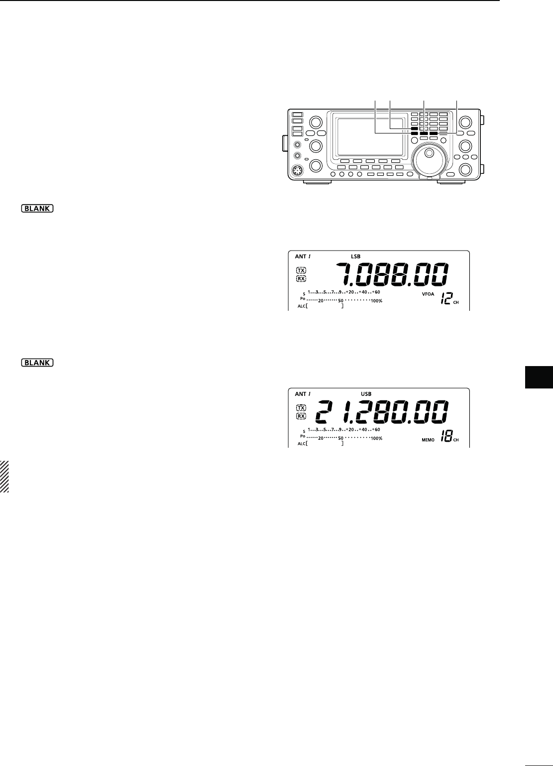
70
MEMORY OPERATION
1
2
3
4
5
6
8
9
11
12
13
14
15
16
17
18
19
20
21
7
10
7
Memory channels can be programmed in either the
VFO mode or the Memory mode.
D0ROGRAMMINGINTHE6&/MODE
q Push [VFO/MEMO] to select the VFO mode.
w Set the frequency, operating mode, and other data
into both VFO A and VFO B.
e Push [Y] or [Z] to select a Memory channel num-
ber to be programmed.
sh” appears if the selected Memory channel is a
blank channel.
r Hold down [MW] for 1 second to program the con-
tents into the Memory channel.
s4HREEBEEPSSOUNDWHENTHEmemory programming is
complete.
D0ROGRAMMINGINTHE-EMORYMODE
q Push [VFO/MEMO] to select the Memory mode.
w Push [Y] or [Z] to select a Memory channel to be
programmed.
s4HECONTENTSOFTHE-EMORYCHANNELAPPEARINTHEDIS-
play.
sh” appears if the selected Memory channel is a
blank channel.
e Enter the frequency, operating mode, and other
data into the Memory channel.
r Hold down [MW] for 1 second to program the con-
tents into the Memory channel.
s4HREEBEEPSSOUNDWHENTHEMEMORYPROGRAMMINGIS
complete.
./4% If you perform the above operations in a pre-
programmed channel, the previous channel data will
be overwritten.
N-EMORYCHANNELPROGRAMMING
;%8!-0,%=
Programming 7.088 MHz/LSB into the Mem-
ory channel 12 while in the VFO mode.
;%8!-0,%=
Programming 21.280 MHz/USB into Memory
channel 18 while in the Memory mode.
[VFO/MEMO] [MW]
[] []
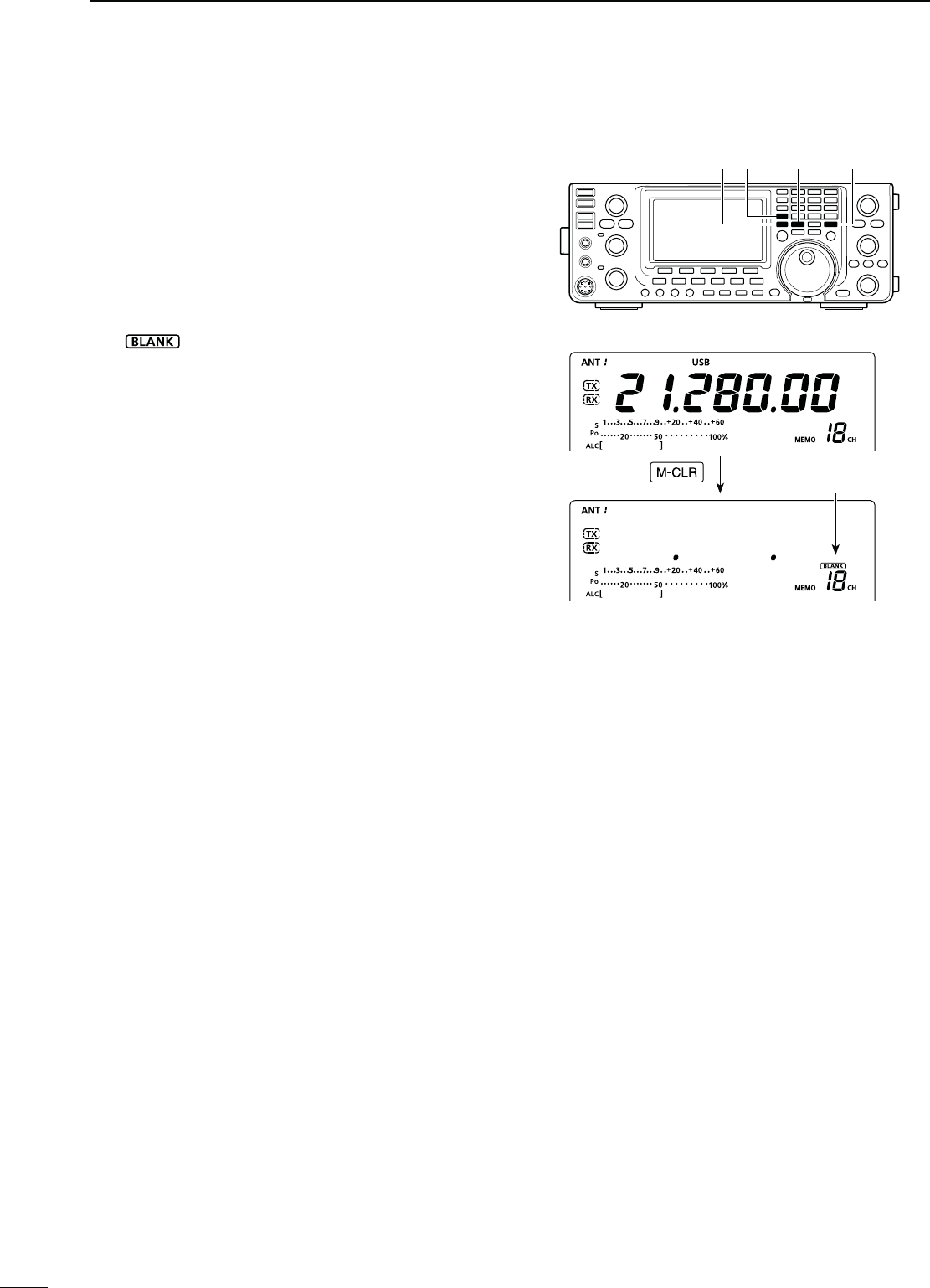
71
MEMORY OPERATION
7
Hold down
N-EMORYCLEARING
Any no-longer-used regular Memory channel can be
cleared, and then become a blank channel.
q Push [VFO/MEMO] to select the Memory mode.
w Push [Y] or [Z] to select a regular Memory channel
to be cleared.
e Hold down [M-CLR] for 1 second to clear the con-
tents.
s4HEPROGRAMMEDCONTENTSDISAPPEAR
sh” appears.
s4HREEBEEPSSOUNDWHENTHEMEMORYCLEARINGISCOM-
plete.
r To clear other Memory channels, repeat steps w
and e.
[VFO/MEMO] [M-CLR]
[] []
Appears
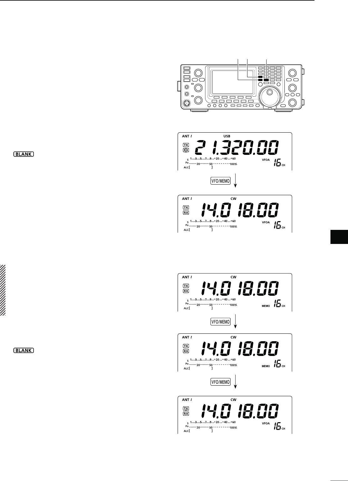
72
MEMORY OPERATION
1
2
3
4
5
6
8
9
11
12
13
14
15
16
17
18
19
20
21
7
10
7
The Memory channel contents (frequency, operating
mode, etc.) can be copied to the VFO.
The copy can be performed in either the VFO mode or
the Memory mode.
D#OPYINGINTHE6&/MODE
This is useful for copying programmed contents to
a displayed VFO.
q Push [VFO/MEMO] to select the VFO mode.
w Push [Y] or [Z] to select a Memory channel num-
ber to be copied.
sh ” appears if the selected Memory channel is a
blank channel. In this case, nothing can be copied.
e Hold down [VFO/MEMO] for 1 second to copy the
Memory channel contents into the VFO.
s4HREEBEEPSSOUNDWHENTHECOPYISCOMPLETE
D#OPYINGINTHE-EMORYMODE
This is useful for copying the Memory channel con-
tents while operating in the Memory mode.
When you have changed the displayed frequency,
operating mode, etc. in the selected Memory chan-
nel:
s$ISPLAYEDdata is copied.
s0ROGRAMMEDcontents in the Memory channel are
not copied, but remain in only the Memory chan-
nel.
q Push [VFO/MEMO] to select the Memory mode.
w Push [Y] or [Z] to select a Memory channel to be
copied.
sh ” appears if the selected Memory channel is a
blank channel. In this case, select another channel.
s3ETTHEFREQUENCYOROPERATINGMODEIFREQUIRED
e Hold down [VFO/MEMO] for 1 second to copy the
Memory channel contents into the VFO.
s4HREEBEEPSSOUNDWHENTHECOPYISCOMPLETE
r Push [VFO/MEMO] to select the VFO mode.
[VFO/MEMO]
[] []
N-EMORYCONTENTSCOPYING
While in the Memory mode
Hold down
Push
While in the VFO mode
Hold down
The Memory channel contents are copied
The Memory channel contents are copied
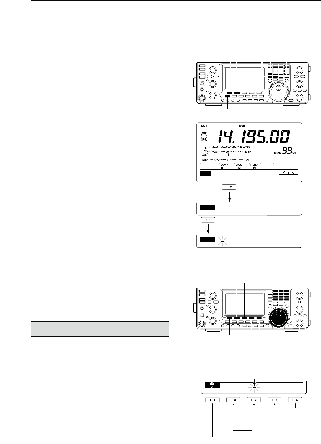
73
MEMORY OPERATION
7
N-EMORYNAMEPROGRAMMING
All Memory channels, including scan edges channels,
can be assigned an alphanumeric names of up to nine
characters each.
;%8!-0,%= Programming a memory name into
Memory channel 99.
q Push [VFO/MEMO] to select the Memory mode.
w Push [Y] or [Z] to select Memory channel 99.
e Push [MENU] one or more times to display the “M2”
screen (Menu 2).
r Push [MEM](F-2) to display the “MEM” screen
(Memory Menu).
t Push [EDT](F-1) to display the “EDT” screen (Mem-
ory Name Edit).
s!CURSORAPPEARSANDBLINKS
s)FTHECHANNELYOUSELECTISABLANKCHANNELANERROR
beep sounds.
y Push [F-1] one or more times to select the desired
character type.
s3EETHEh#HARACTERTABLELISTvBELOW
u Rotate [DIAL] to select the first character to input.
s7HENINPUTTINGNUMBERSANDADECIMALPOINTPUSHTHE
appropriate keypad key.
s0USH;$%,=&TODELETETHESELECTEDCHARACTER
s0USH;30#=&TOINPUTASPACE
s!NERRORBEEPSOUNDSIFYOUTRYTOPROGRAMMORETHAN
nine characters. If you want to reprogram the name,
push [Ω](F-2) or [≈](F-3) to select any undesired char-
acter, then push [DEL](F-4) to delete it.
i Push [Ω](F-2) to move the cursor backward, or push
[≈](F-3) to move the cursor forward.
o Repeat steps y to i to program a memory name
of up to 9 characters.
!0 Push [MENU] to save the name, and return to the
“MEM” screen.
!1 Push [MENU] again to return to the “M2” screen.
#HARACTERTABLELIST
#HARACTER
type 3ELECTABLECHARACTERS
ABC A to Z
abc a to z
etc <" ’ ` ^ + – 1⁄ . , : ; = < > ( ) [ ] { }
¦ _ ¯ @
[][] Keypad
[DEL][F-1] [SPC] [DIAL]
s7HENPROGRAMINGAMEMORYNAME
abc
DEL SPC
EDT
DX
spot
Character type Cursor
Input a space
Delete a character
Move cursor forwards
Move cursor backwards
Select character type
;%8!-0,%=Programming “DX spot” into Memory
channel 99.
[VFO/MEMO] [MEM] [EDT]
[MENU]
[] []
SCAN MEM SWR TCON VSC
M2
EDT ( ) SEL
MEM
14.19500 USB
ABC
DEL SPC
EDT
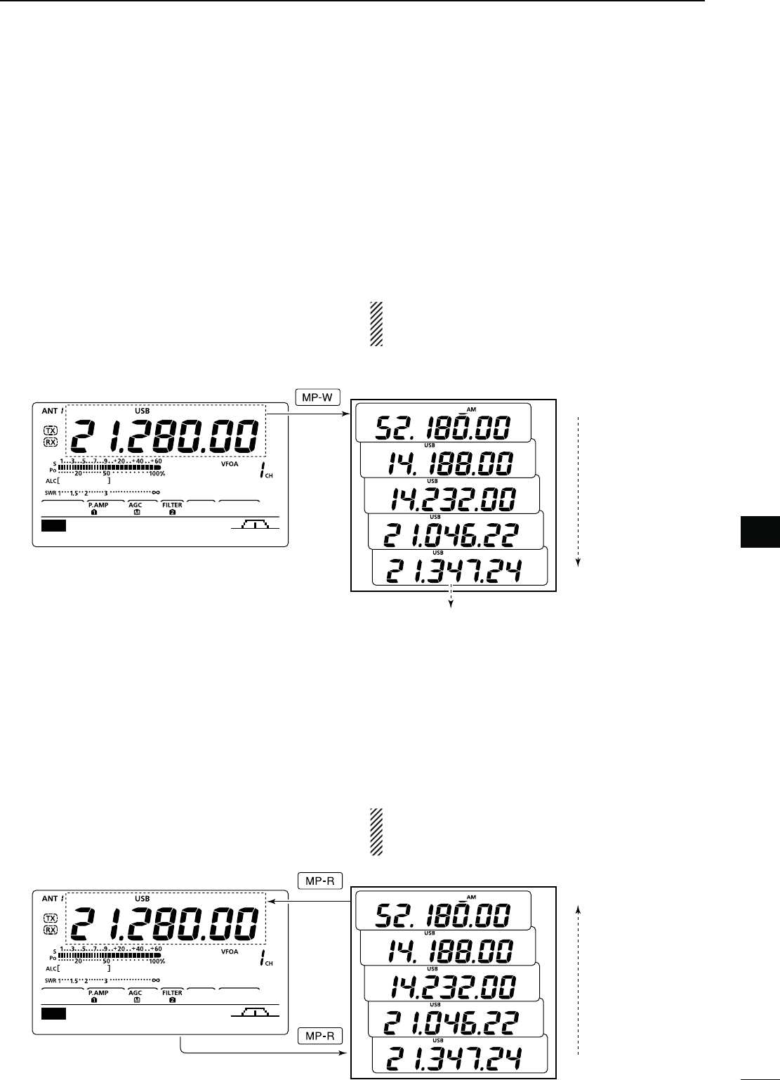
74
MEMORY OPERATION
1
2
3
4
5
6
8
9
11
12
13
14
15
16
17
18
19
20
21
7
10
7
You can call up a memo pad by pushing [MP-R] while
in either the VFO or Memory mode.
s4HEMEMOPADDATAISCALLEDUPSTARTINGFROMTHEMOST
recently written.
When you call up a memo pad, the previously dis-
played data is automatically stored in a temporary
pad. The temporary pad can be recalled by pushing
[MP-R].
s9OUMAYTHINKTHEREAREMEMOPADSBECAUSEDIFFERENT
frequencies (5 in memo pads and 1 in the temporary pad)
are called up by [MP-R].
If you change the data called up from a memo pad,
the stored temporary pad data is replaced with the
changed data.
N-EMO0ADFUNCTION
The transceiver has a Memo Pad function to store
the displayed data for easy writing and recalling. The
memo pads are separate from the Memory channels.
The default number of memo pads is 5. However, you
can increase the number to 10 in the “Memopad Num-
bers” item of the Set mode, if desired. (p. 87)
Memo pads are convenient when you want to memo-
rize the displayed data temporarily, such as when you
find a DX station in a pile-up, or when a desired station
is busy for a long time and you want to temporarily
search for other stations.
Use the transceiver’s memo pads instead of relying on
hastily scribbled notes that are easily misplaced.
D7RITINGTHEDISPLAYEDDATAINTOAMEMOPAD
You can store the displayed data by pushing [MP-W].
When you store the 6th data into memo pads, the old-
est stored entry is automatically erased, to make room
for the new data.
./4%Each memo pad must have its own unique
set of data; memo pads having identical data cannot
be written.
D #ALLINGUPAMEMOPAD
In this example, 21.347 MHz (USB) will be
erased when 21.280 MHz (LSB) is written.
Memo pads
Erased
Newest
Oldest
AGC TBW SCP
M1
Newest
Oldest
Memo pads
AGC TBW SCP
M1
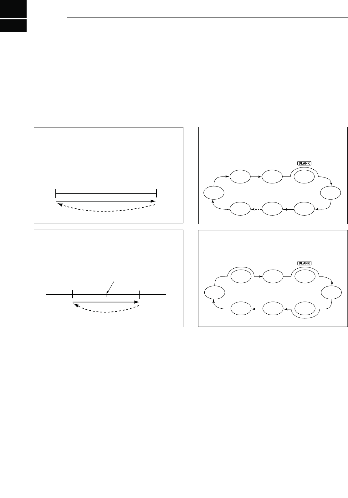
75
SCANS
8
Scan
–∂F frequency +∂F frequency
Center frequency
(Start frequency)
Jump
Mch 1 Mch 5
Mch 2 Mch 3 Mch 4
Mch 6Mch 7Mch 99
SEL
SELSEL
SEL SEL
Mch 1 Mch 5
Mch 2 Mch 3 Mch 4
Mch 6Mch 7Mch 99
SEL
SELSEL
SEL SEL
Scan
P1 or P2
Jump
Scan edge
P2 or P1
Scan edge
N3CANTYPES
Scanning automatically searches for signals and
makes it easier to locate new stations for contact or
listening purposes. The IC-7410 has several scan
types; Programmed scan, Memory scan, ∂F (Delta
Frequency) scan, and Select Memory scan.
MEMORY SCAN (p. 79)
Repeatedly scans all programmed Memory chan-
nels.
This scan operates in the memory mode.
PROGRAMMED SCAN (p. 78)
Repeatedly scans between scan edges (Program
Scan Edge channels P1 and P2).
This scan operates in the VFO mode.
SELECT MEMORY SCAN (p. 80)
Repeatedly scans all Select Memory channels.
This scan operates in the memory mode.
∂F SCAN (p. 81)
Repeatedly scans within the ∂F span area.
This scan operates in both VFO and memory
modes.
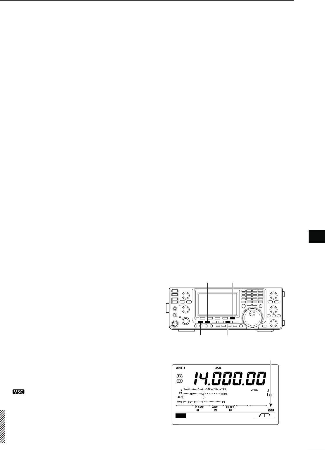
76
SCANS
1
2
3
4
5
6
7
9
10
12
13
14
15
16
17
18
19
20
21
11
8
8
N Preparation
&ORA0ROGRAMMEDSCAN
Program scan edge frequencies into Program Scan
Edge channels “P1” and “P2,” in the same manner as
programming Memory channels (p. 70)
&ORA-EMORYSCAN
Program two or more Memory channels. (Program
Scan Edge channels will not be scanned.) (p. 70)
&ORA3ELECT-EMORYSCAN
Set two or more Memory channels as Select Memory
channels. (p. 80)
For a ∂&SCAN
Set the ∂F span (∂F scan range) in the “SCAN”
screen. (p. 81)
s3CAN2ESUMEFUNCTION
You can select the scan to resume or cancel, after
detecting a signal, in the Scan Set mode. The Scan
Resume function must be set before starting a scan.
(p. 77)
s3CANSPEED
The scan speed can be set to high or low, in the Scan
Set mode. (p. 77)
s3QUELCHSTATUS
M4HESCANSTARTSWITHTHESQUELCHOPEN
&ORAPROGRAMMEDSCAN
When the tuning step is 1 kHz or less:
The scan continues until it is stopped manually— it
does not pause*, even if signals are detected.
* The scan is paused when the squelch is closed and then
opens. The scan resumes, or is cancelled, depending on
the “Scan Resume” setting. (p. 77)
When the tuning step is 5 kHz or more:
If Scan Resume is ON, the scan pauses when a signal
is detected, then resumes.
If the Scan Resume is OFF, the scan does not re-
sume.
&ORA-EMORYSCAN
If Scan Resume is ON, the scan pauses on each chan-
nel when a signal is detected, then resumes.
If Scan Resume is OFF, the scan does not start.
M4HESCANSTARTSWITHSQUELCHCLOSED
The scan pauses when signals are detected. The scan
resumes, or is cancelled, depending on the “Scan Re-
sume” setting. (p. 77)
-ODE33"!-&-
This function is useful when you do not want unmodu-
lated signals pausing or cancelling a scan. When the
Voice Squelch Control (VSC) function is ON, the re-
ceiver checks received signals for voice components.
The scan pauses, or is cancelled, if a received signal
includes voice components, and the tone of the voice
components changes within 1 second.
The scan resumes if the received signal includes no
voice components, or the tone of the voice compo-
nents does not change within 1 second.
q Push [SSB] or [AM/FM] once or twice to select the
operating mode.
w Push [MENU] to display the “M2” screen (Menu 2).
e Push [VSC](F-5) to turn the VSC function ON or
OFF.
sh ” appears when the VSC function is ON.
s0USH;-%.5=TORETURNTOTHEPREVIOUSDISPLAY
s4HE63#FUNCTIONISAVAILABLEFORPHONEMODES
(SSB, AM and FM).
s4HE63#FUNCTIONRESUMESTHESCANONUNMODU-
lated signals, regardless of whether the Scan Re-
sume function is set to ON or OFF.
N6OICE3QUELCH#ONTROLFUNCTION
Appears
SCAN MEM SWR TCON VSC
M2
[VSC] [SSB]
[MENU] [AM/FM]
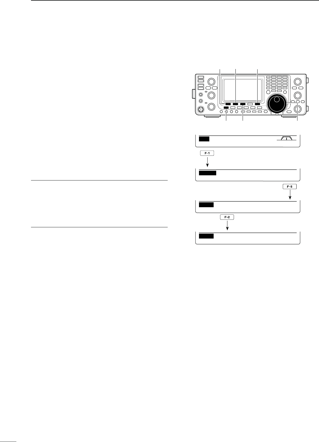
77
SCANS
8
N3CAN3ETMODE
The scan speed and the Scan Resume function can
be set in the Scan Set mode.
q
P
ush [MENU] one or more times to display the “M2”
screen (Menu 2).
w Push [SCAN](F-1) to display the “SCAN” screen.
e Push [SET](F-5) to enter the Scan Set mode.
r Push [Y](F-1) or [Z](F-2) to select the desired
item.
t Rotate [DIAL] to select the desired option.
s(OLDDOWN;&=FORSECONDTORESETTOTHEDEFAULTSET-
ting.
y Push [MENU] to save, and return to the “SCAN”
screen.
u
Push [MENU] again to return to the “M2” screen.
[SET] [SCAN]/[]
[MENU] [F-3] [DIAL]
[]
3#!.3PEED1. $EFAULT()'(
Select the desired scan speed between high and low.
s()'( 4HESCANISFASTER
s,/7 : The scan is slower.
3#!.2ESUME2. $EFAULT/.
Set the Scan Resume function ON or OFF.
s/. 7HENASIGNALISDETECTEDTHESCANPAUSESFOR
10 seconds, then resumes. When a signal dis-
appears, the scan resumes 2 seconds later.
s/&&7HENASIGNALISDETECTEDTHESCANISCAN-
celled.
SCAN ME M S WR TCON VS C
M2
PRO FSPAN S E TFIN
SCAN
F
:
10k
Ú
SCAN Speed
Ù1 HIGH
SET
Ú
SCAN Resume
Ù2ON
SET
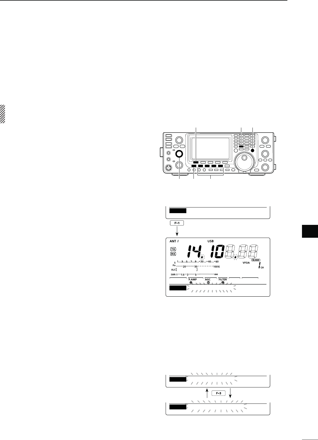
78
SCANS
1
2
3
4
5
6
7
9
10
12
13
14
15
16
17
18
19
20
21
11
8
8
A programmed scan searches for signals between
Program Scan Edge channels “P1” and “P2.”
Before starting the programmed scan, scan edges
must be programmed into these channels.
Refer to “N Memory Channel programming” to pro-
gram Program Scan Edge channels. (p. 70)
If the same frequencies are programmed into the
Program Scan Edge channels, the programmed
scan will not start.
q Push [VFO/MEMO] to select the VFO mode.
w Push the mode switch to select the desired operat-
ing mode.
s4HEOPERATINGMODECANALSOBECHANGEDWHILESCAN-
ning.
e Push [TS] one or more times to select a tuning step.
(p. 27)
s4HETUNINGSTEPCANALSOBECHANGEDWHILESCANNING
r
P
ush [MENU] once or twice to display the “M2”
screen (Menu 2).
t
P
ush [SCAN](F-1) to display the “SCAN” screen.
y Rotate the [RF/SQL] control to set the squelch to
open or closed.
s4HESCANPERFORMANCEDIFFERSDEPENDINGONTHESQUELCH
setting when the scan was started. See page 76 for de-
tails.
s)FTHE;2&31,=CONTROLFUNCTIONISSETTOh!54/vTHE
squelch is always open in the SSB, CW and RTTY
modes. (pp. 2, 32, 86)
u Push [PRO](F-1) to start or cancel the programmed
scan.
s4HE-(ZANDK(ZDECIMALPOINTSANDh02/'3#!.v
blink while scanning.
s2OTATING;$)!,=ALSOCANCELSTHESCAN
N0ROGRAMMEDSCAN&INEPROGRAMMEDSCAN6&/MODE
D!BOUTTHE&INEPROGRAMMEDSCAN
When a signal is received during Fine programmed
scan, the scanning tuning step is temporarily set to
10 Hz and the scan speed decreases.
q Start the programmed scan.
s&OLLOWSTEPSq through u as described above.
w While scanning, push [FIN](F-3) to switch the scan
function between a programmed scan and a Fine
programmed scan.
sh&02/'3#!.vBLINKSWHILE&INEPROGRAMMEDSCAN-
ning.
e Push [PRO](F-1) to cancel the scan.
s2OTATING;$)!,=ALSOCANCELSTHESCAN
[SCAN]/[PRO] [VFO/MEMO] [TS]
[MENU][RF/SQL] Mode switches
While Programmed scanning
PRO FSPAN S E TFIN
SCAN
F
:
10k
PRO ∂FSPAN S E TFIN
SCAN
PROG SCAN
PRO ∂FSPAN S E TFIN
SCAN
PROG SCAN
PRO ∂FSPAN S E TFIN
SCAN
F−PROG SCAN
While Fine programmed scanning
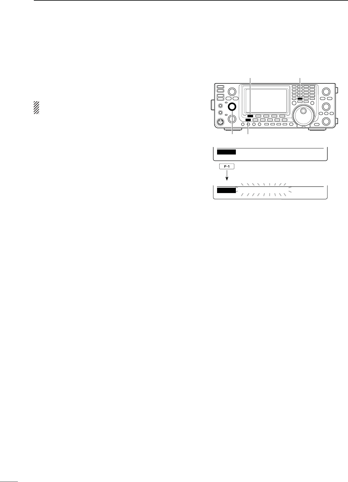
79
SCANS
8
D-EMORYSCAN
A Memory scan searches for signals through Memory
channels 1 to 99.
Blank (unprogrammed) channels are skipped.
./4% To start a Memory scan, two or more Mem-
ory channels must be programmed. (p. 70)
q Push [VFO/MEMO] to select the Memory mode.
w
P
ush [MENU] to display the “M2” screen (Menu 2).
e
P
ush [SCAN](F-1) to display the “SCAN” screen.
r Rotate the [RF/SQL] control to set the squelch to
open or closed.
s4HESCANPERFORMANCEDIFFERSDEPENDINGONTHESQUELCH
setting when the scan was started. See page 76 for de-
tails.
s)FTHE;2&31,=CONTROLFUNCTIONISSETTOh!54/vTHE
squelch is always open in the SSB, CW and RTTY
modes. (pp. 2, 32, 86)
t Push [MEM](F-1) to start or cancel the Memory
scan.
s4HE-(ZANDK(ZDECIMALPOINTSANDh-%-/3#!.v
blink while scanning.
s2OTATING;$)!,=ALSOCANCELSTHESCAN
N-EMORYSCAN-EMORYMODE
[SCAN]/[MEM] [VFO/MEMO]
[MENU][RF/SQL]
While Memory scanning
MEM FSPAN S E TSEL
SCAN
F
:
10k
MEM ∂FSPAN S E TSEL
SCAN
MEMO SCAN
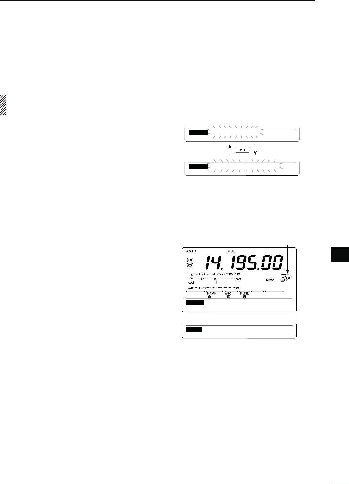
80
SCANS
1
2
3
4
5
6
7
9
10
12
13
14
15
16
17
18
19
20
21
11
8
8
D3ELECT-EMORYSCAN
Select Memory scan searches for signals through
Memory channels programmed as “Sel” (Select).
./4% To start a Select Memory scan, two or more
Memory channels must be designated as Select
Memory channels.
q Start a Memory scan.
s&OLLOWSTEPSq through t on the previous page.
w While scanning, push [SEL](F-3) to switch the scan
function between a Memory scan and a Select
Memory scan.
sh3%,-%-/3#!.vBLINKSWHILE3ELECT-EMORYSCAN-
ning.
e Push [MEM](F-1) to cancel the scan.
s2OTATING;$)!,=ALSOCANCELSTHESCAN
All Memory channels can be set as Select Memory
channels, except for the Scan Edge channels.
± When the “SCAN” screen is displayed, push [SEL]
(F-3), or when the “MEM” screen (Memory Menu)
is displayed, push [SEL](F-5) to set or cancel the
displayed Memory channel as a Select Memory
channel.
sh3%,vAPPEARSWHEN THE CHANNEL ISSETAS A 3ELECT
Memory channel.
s!N ERROR BEEP SOUNDS WHEN THE DISPLAYED -EMORY
channel is a blank channel.
s(OLDINGDOWN;3%,=&OR;3%,=&FORSECONDDIS-
plays “SEL ALL Clear?.” Hold down [YES](F-4) to clear
all Select Memory channel settings.
MEM ∂FSPAN S E TSEL
SCAN
MEMO SCAN
MEM ∂FSPAN S E TSEL
SCAN
SEL−MEMO SCAN
MEM FSPAN S E TSEL
SCAN
F
:
10k
Appears
“SCAN” screen
“MEM” screen (Memory Menu)
While Select Memory scanning
D 3ETTING#ANCELLING3ELECT-EMORYCHANNELS
EDT ( ) SEL
MEM
14.19500 USB
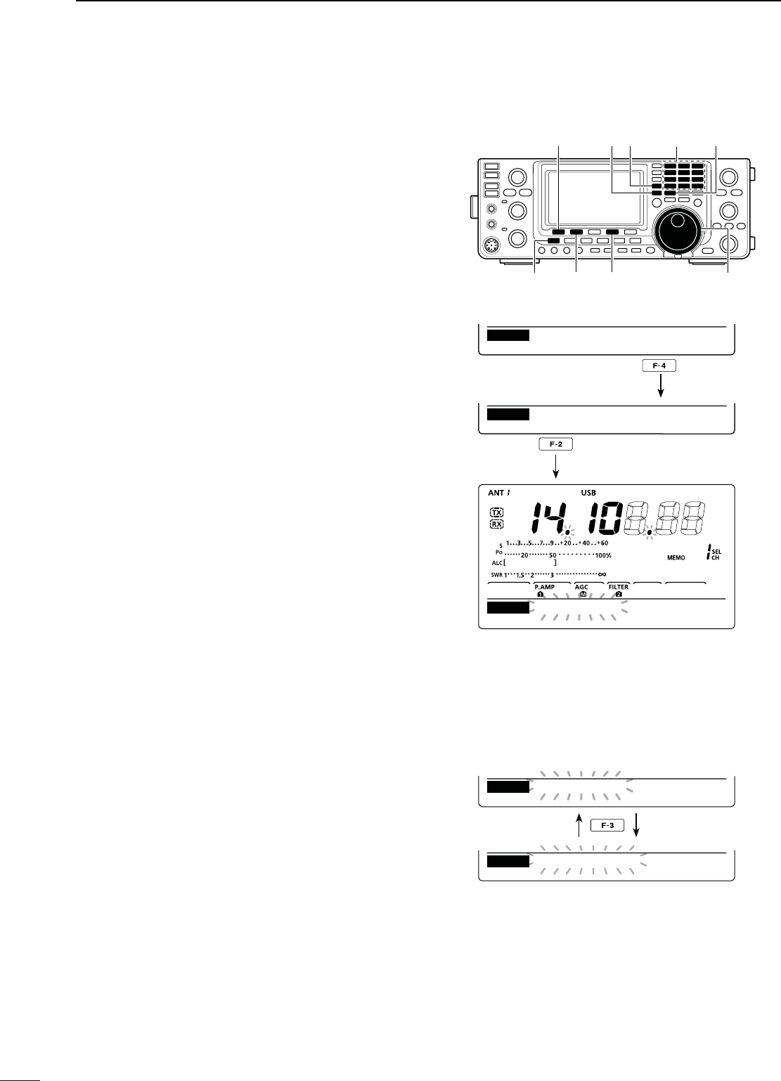
81
SCANS
8
∂F (Delta Frequency) scan searches for signals within
the specified range with the displayed VFO frequency
or Memory channel frequency as the center frequency.
The frequency range is specified by the width of the
selected span.
q Push [VFO/MEMO] once or twice to select the VFO
mode or Memory mode.
w
P
ush [MENU] one or more times to display the “M2”
screen (Menu 2).
e
P
ush [SCAN](F-1) to display the “SCAN” screen.
r Rotate the [RF/SQL] control to set the squelch to
open or closed.
s4HESCANPERFORMANCEDIFFERSDEPENDINGONTHESQUELCH
setting when the scan was started. See page 76 for de-
tails.
s)FTHE;2&31,=CONTROLFUNCTIONISSETTOh!54/vTHE
squelch is always open in the SSB, CW and RTTY
modes. (pp. 2, 32, 86)
t Push [SPAN](F-4) one or more times to select the
desired ∂F span width.
sÒ K(Z Ò K(Z Ò K(Z Ò K(Z Ò K(Z
±500 kHz and ±1 MHz are selectable.
y Set the center frequency of the ∂F scan.
s)NTHE6&/MODEPUSHTHEKEYPADORROTATE;$)!,=TO
set the center frequency.
s)NTHEMEMORYMODEPUSH;Y] or [Z] to select the de-
sired Memory channel whose frequency will be the cen-
ter frequency.
u Push [∂F](F-2) to start or cancel the ∂F scan.
sh∂F SCAN,” the MHz and kHz decimal points blink while
scanning.
s2OTATING;$)!,=ALSOCANCELSTHESCAN
N ∂&SCANAND&INE∂&SCAN
D!BOUTTHE&INE∂&SCAN
When a signal is received during Fine ∂F scan, the
scanning tuning step is temporarily set to 10 Hz and
the scan speed decreases.
q Start a ∂F scan.
s&OLLOWSTEPSq through u as described above.
w While scanning, push [FIN](F-3) to switch the scan
function between ∂F scan and Fine ∂F scan.
sh&∂F SCAN” blinks while Fine ∂F scanning.
e Push [∂F](F-2) to cancel the scan.
s2OTATING;$)!,=ALSOCANCELSTHESCAN
While ∂F scanning
MEM FSPAN S E TFIN
SCAN
MEM FSPAN S E TFIN
SCAN
F−
F
SCAN
F
SCAN
20k
20k
While Fine ∂F scanning
[SCAN] [VFO/MEMO]
[MENU] [F] [SPAN] [DIAL]
[] [] Keypad
MEM FSPAN S E TSEL
SCAN
F
:
10k
MEM FSPAN S E TSEL
SCAN
F
:
20k
F
SCAN
MEM FSPAN S E TSEL
SCAN
20k
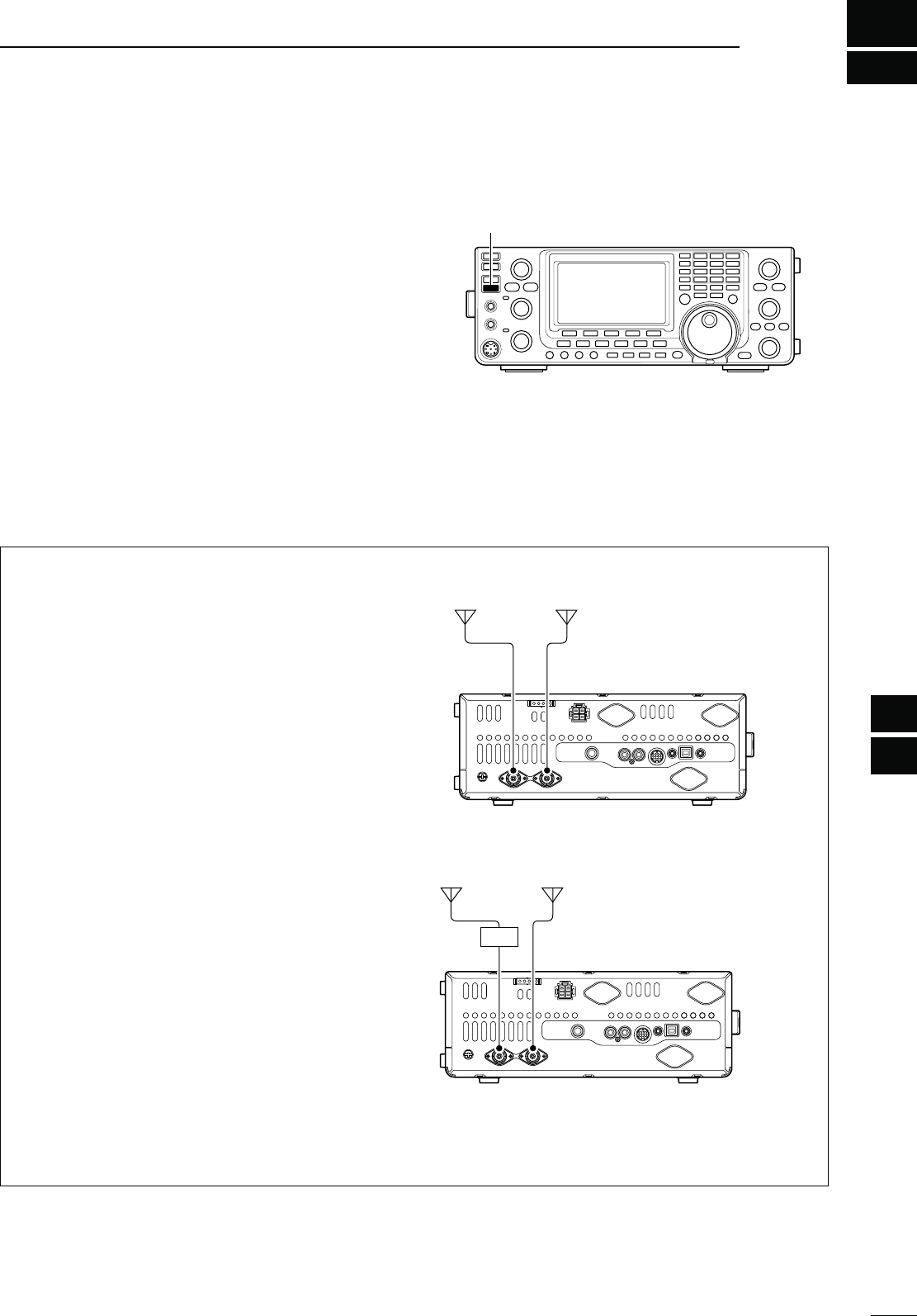
82
1
2
3
4
5
6
7
10
11
12
14
15
16
17
18
19
20
21
8
ANTENNA TUNER OPERATION
9
13
9
The IC-7410 has 2 antenna connectors for the HF/50
MHz bands, [ANT1] and [ANT2].
You can memorize the antenna for each operating
band the IC-7410 covers.
When you change the operating band, the previously
set antenna connector for that band is automatically
selected. (See below)
This function is especially convenient when you use 2
antennas for HF and 50 MHz band operation.
To use the band memory, set the “[ANT] Switch” item
to “Auto” in the Set mode. (p. 87)
s!NTENNASELECTIONMODEh!UTOv (default)
Once an antenna has been selected for use with a
BANDBYPUSHING;!.4s-%4%2=THEANTENNAISAUTO-
matically selected whenever that band is accessed.
;%8!-0,%= a 3.5/7 MHz antenna is connected to
[ANT1], a 21/28/50 MHz antenna is connected to
[ANT2]. When the antenna selector function is set to
“Auto,” the correct antenna is automatically selected
when you changes bands.
s!NTENNASELECTIONMODEh-ANUALv
;!.4s-%4%2=FUNCTIONSHOWEVERTHEBANDMEMORY
function is disabled. In this case, you must select an
antenna manually.
;%8!-0,%= an optional antenna tuner and HF an-
tenna are connected to [ANT1] and a 50 MHz an-
tenna is connected to [ANT2].
s!NTENNASELECTIONMODEh/&&v
;!.4s-%4%2=DOESNOTFUNCTION4HE;!.4=CON-
nector is always selected for HF and 50 MHz bands
operation.
N!NTENNACONNECTIONANDSELECTION
[ANT2][ANT1]
3.5/7 MHz
bands
21/28/50 MHz
bands
[ANT2][ANT1]
AH-4
HF
bands
50 MHz
bands
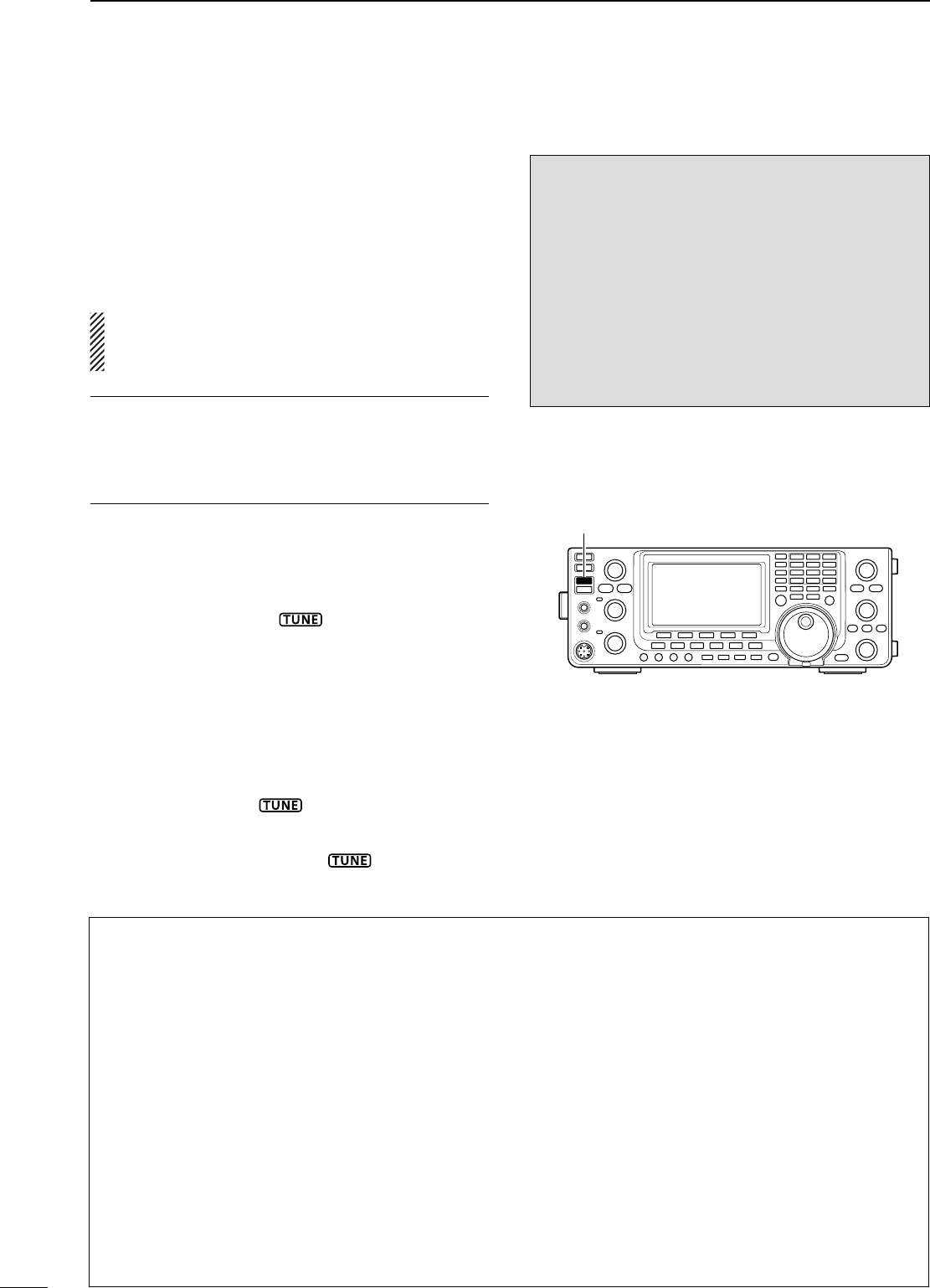
83
ANTENNA TUNER OPERATION
9
M )FTHETUNERCANNOTTUNETHEANTENNACHECKTHE
FOLLOWINGANDTRYAGAIN
sTHECORRECTANTENNACONNECTORSELECTION
sTHEANTENNACONNECTIONANDFEEDLINE
sTHEUNTUNEDANTENNA372,ESSTHANFORTHE
HF bands; Less than 2.5:1 for the 50 MHz band)
sTHETRANSMITPOWER7FORTHE(&BANDS7FOR
the 50 MHz band)
sTHEPOWERSOURCEVOLTAGECURRENTCAPACITY
If the tuner still cannot reduce the SWR to less than
1.5:1 after checking the above, perform the following:
sTRYMANUALTUNINGONEORMORETIMES
sADJUSTTHEANTENNAFEEDLINELENGTH4HISISEFFECTIVE
for higher frequencies in some cases.)
Even if manual tuning does not tune the antenna and
the tuner turns OFF the first time, it may tune the an-
tenna the second time.
M4UNINGANARROWBANDWIDTHANTENNA
Some antennas, especially for the low bands, have
a narrow bandwidth. These antennas may not be
tuned beyond the edge of their operating bandwidth,
therefore, manually tune such an antenna as follows:
;%XAMPLE= Suppose you have an antenna which has
an SWR of 1.5:1 at 3.55 MHz and an
SWR of 3:1 at 3.8 MHz.
q Select 3.55 MHz and hold down [TUNER] for 1
second. to start manual tuning.
w Select 3.80 MHz and hold down [TUNER] for 1
second to start manual tuning.
./4%3
sNEVER transmit without an antenna properly con-
nected to each antenna port in use.
s7HENANTENNASARECONNECTEDSELECT THEAN-
TENNATOBEUSEDBYPUSHING;!.4s-%4%2=
s)FTHE372ISHIGHERTHANABOUTWHENTUN-
ing farther than 100 kHz from an antenna’s pro-
grammed preset point, hold down [TUNER] for
1 second to start manual tuning.
s4HEINTERNALTUNERMAYNOTBEABLETOTUNEINthe
AM mode. In such case, hold down [TUNER] for
1 second to manually tune.
[TUNER]
N!NTENNATUNEROPERATION
The internal automatic antenna tuner automatically
matches the transceiver to the selected antenna. After
the tuner matches an antenna, the variable capacitor
settings are memorized as a preset point for each fre-
quency range (100 kHz steps). Therefore, when you
change the frequency range, the variable capacitors
are automatically preset to the memorized setting.
#!54)/..%6%2 transmit with the tuner ON when
no antenna is connected. This will damage the
transceiver. Be careful of the antenna selection.
For your convenience
When you purchase a brand-new antenna, or you
want to change the antenna settings, you can erase
all of the internal antenna tuner preset points with
“Tuner Preset Clear” in the Set mode. (p. 87)
D 4UNEROPERATION
± Push [TUNER] to turn ON the internal antenna
tuner. The antenna is automatically tuned when the
antenna SWR is higher than 1.5:1.
s7HENTHETUNERIS/.h ” appears.
D-ANUALTUNING
If you transmit in SSB with a soft voice, the internal
tuner may not automatically tune correctly. In such
case, manual tuning is helpful.
± Hold down [TUNER] for 1 second to start manual
tuning.
s!SIDETONESOUNDSh ” blinks and the TX indicator
lights red while tuning.
s)FTHETUNERCANNOTREDUCETHE372TOLESSTHAN
within 20 seconds of tuning, “ ” disappears and
the TX indicator goes out.
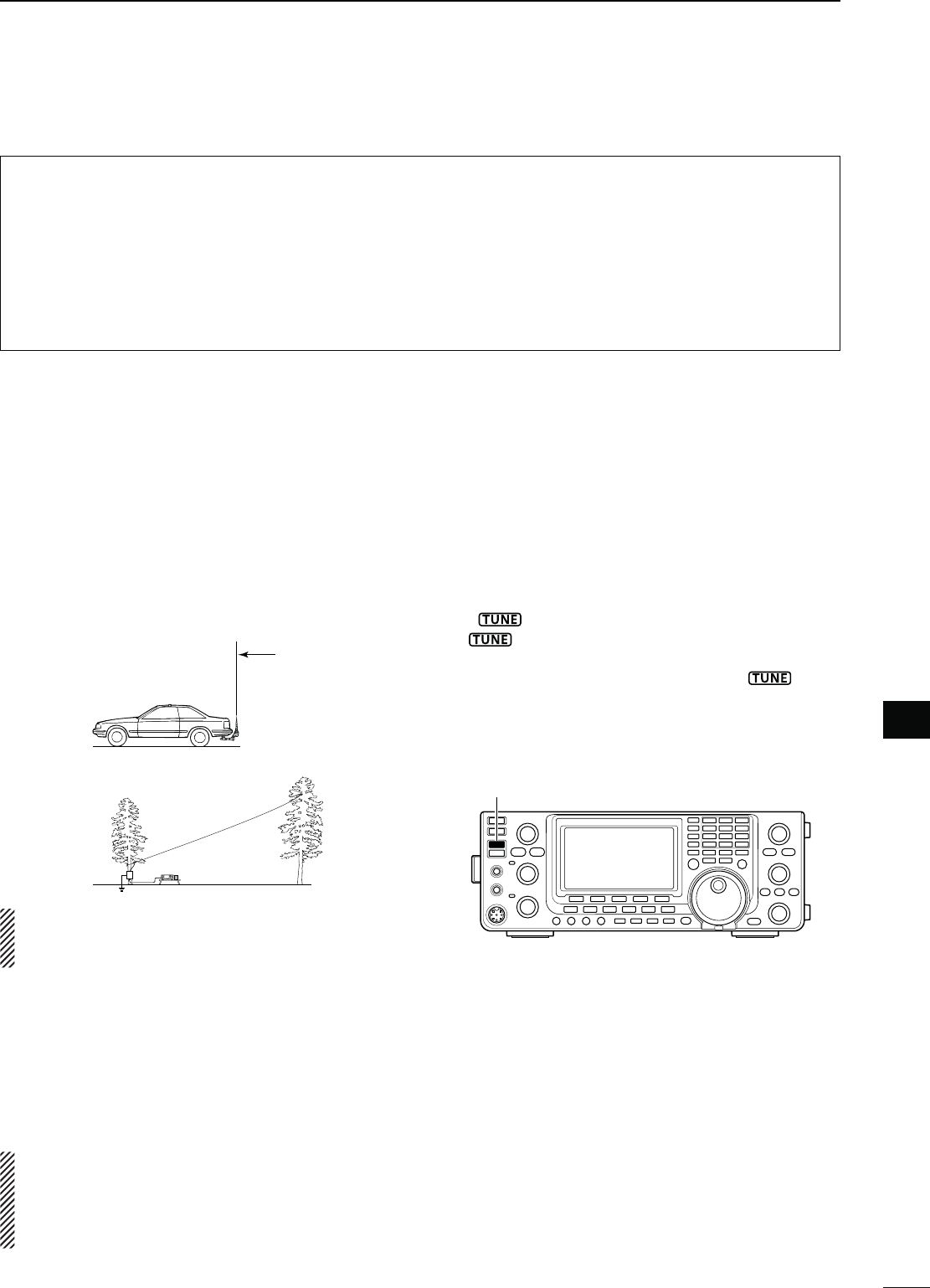
84
ANTENNA TUNER OPERATION
1
2
3
4
5
6
7
8
10
11
12
14
15
16
17
18
19
20
21
13
9
9
sAH-4 HF/50 MHz AUTOMATIC ANTENNA TUNER
The optional AH-4 matches the IC-7410 to a long
wire antenna more than 7 m/23 ft long (3.5 MHz and
above).
s3EEPAGE FORTHETRANSCEIVER AND !(CONNEC-
tion.
s3EETHE!(INSTRUCTIONMANUALFOR!(INSTALLATION
and antenna connection details.
AH-4 setting example:
For mobile operation
For outdoor operation
Long wire
Optional AH-2b
antenna element
R$!.'%2()'(6/,4!'%
NEVER touch the antenna element while tuning
or transmitting.
NEVER operate the AH-4 without an antenna wire or
element. The tuner and transceiver will be damaged.
NEVER operate the AH-4 when it is not grounded.
Transmitting before tuning may damage the trans-
ceiver. Note that the AH-4 cannot tune when using a
1⁄2 λ long wire or multiple of the operating frequency.
When connecting the AH-4, the antenna connector
assignments are [ANT2] for the internal tuner and
[ANT1] for the AH-4. The antenna icon in the LCD
displays “ANT” when the AH-4 is connected and se-
lected.
sAH-4 operation
Tuning is required for each frequency. Be sure to re-
tune the antenna before transmitting when you change
the frequency— even slightly.
q Select the desired frequency for use with the AH-4.
s4HE!(WILLNOTOPERATEONFREQUENCIESOUTSIDE
the ham bands.
w Hold down [TUNER] for 1 second.
s
“ ” blinks while tuning.
e “” appears constantly when tuning is com-
plete.
s7HENTHEWIREANTENNACANNOTBETUNEDh ” disap-
pears and the AH-4 is bypassed. At that point the an-
tenna wire connection root is to the transceiver directly,
and not via the AH-4 antenna tuner.
r
To bypass the AH-4 manually, push [TUNER].
[TUNER]
s!NTENNATUNEROFTHE)#07%52/
When using an external antenna tuner such as that
in the IC-PW1/EURO, tune when the internal tuner is
turned OFF. After the antenna has been matched, turn
ON the internal tuner.
Otherwise, both tuners simultaneously tune, and
proper antenna matching may fail.
See the instruction manual included with each antenna
tuner for their respective operations.
N/PTIONALEXTERNALTUNEROPERATION
s!UTOMATICTUNERSTART (HF bands only)
If you want to deactivate the tuner when the VSWR
is 1.5:1 or less, use the Auto Tuner Start function
and turn OFF the tuner. This function activates the
tuner automatically when the SWR is high, and is
controlled in the Set mode. (p. 86).
s4HE TUNER MAY NOT BE ACTIVATED IF THE 48 POWER OUTPUT
is not stable longer than the specified time period in the
SSB or CW mode operation.
s044TUNERSTART
Tuning of the internal*/external antenna tuner starts
when [PTT] is pushed on a new frequency that is
MORE THAN AWAY FROM THE LASTTUNED FREQUENCY
This function removes the “holding down [TUNER]”
operation, and starts tuning on the first transmission
on a new frequency.
This function is turned ON in the Set mode. (p. 87).
*Tuning starts if the internal antenna tuner is ON.
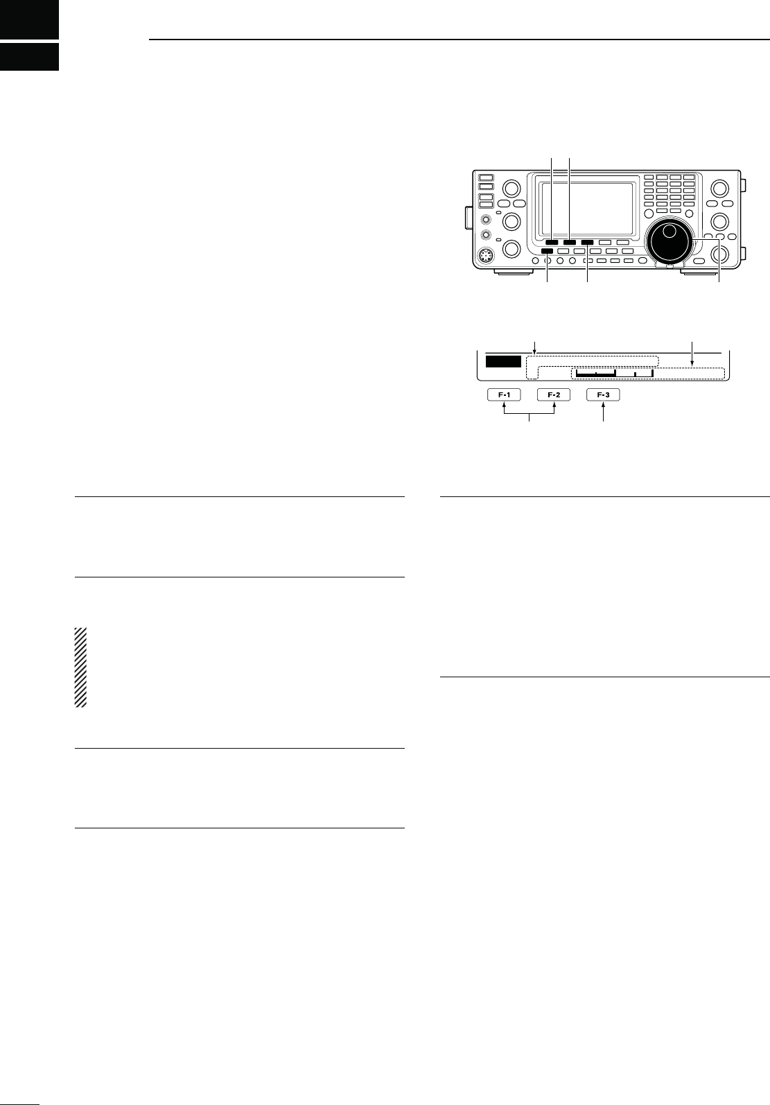
85
SET MODE
10
N3ETMODEDESCRIPTION
The Set mode is used for programming infrequently
changed values or functions.
D 4HE3ETMODESETTINGS
q
Hold down
[MENU] for 1 second to enter the Set
mode.
w Push [Y](F-1) or [Z](F-2) to select the desired
item.
e Rotate [DIAL] to select the desired option.
s(OLDDOWN;&=FORSECONDTORESETTOTHEDEFAULTSET-
ting, if desired.
r Push [MENU] to save, and exit the Set mode.
Select the item Reset to the default
setting
[]
[MENU] [F-3] [DIAL]
[][]
Ù 1 Ú50%
SET LCD Contrast
Displays the Set mode
item name and number Displays the option
,#$#ONTRAST1. $EFAULT
!DJUSTTHE,#$CONTRASTTOBETWEENANDIN
STEPS
,#$"ACKLIGHT2. $EFAULT
!DJUSTTHE,#$BACKLIGHTBRIGHTNESSTOBETWEEN
ANDINSTEPS
./4% Regardless of this setting, the LCD backlight
BRIGHTNESSISMAXIMUMATPOWER/.BYDE-
sign. (It is not an equipment malfunction.) Then, the
brightness level automatically returns to the ad-
justed value.
"EEP,EVEL3. $EFAULT
Adjust the confirmation and band edge beep tones
OUTPUTLEVELTOBETWEENANDINSTEPS
"EEP,EVEL,IMIT4. $EFAULT/.
Turn the confirmation and band edge beep tones out-
put level limiting ON or OFF.
When you set this item to ON, the beep tones are ad-
justed by the [AF] control until rotating the [AF] control
reaches the level specified in the
“Beep Level” item, as
described above
. Further rotation will not increase the
volume of the beep tones.
s/&&"EEPLEVELADJUSTMENTISNOTLIMITED
s/. "EEPLEVELADJUSTMENTISLIMITEDTOTHELEVEL
specified in 3, above.
"EEP5. $EFAULT/.
Turn the confirmation beep ON or OFF.
Set the beep output level in
the “Beep Level” item, as
described to the left
.
s/&&4HECONlRMATIONBEEPIS/&&3ILENTOPERA-
tion)
s/. 4HECONFIRMATION BEEPSOUNDSEACH TIMEA
switch is pushed.
"AND%DGE"EEP6. $EFAULT/.$EFAULT
When you tune into or out of an amateur band’s fre-
quency range, you can hear a beep tone.
)FYOUSELECTh/.5SERvORh/.5SER48,IMITvYOU
can program a total of 30 band edge frequencies in
the “User band Edge” item.
You can set the beep output level in
the “Beep Level”
item as described to the left
.
s/&& "ANDEDGEBEEPIS/&&
s/.$EFAULT 7HENYOUTUNEINTOOROUTOFTHE
default amateur band’s frequency
range, a beep sounds.
s/.5SER 7HENYOUTUNEINTOOROUTOFAUSER
programmed amateur band’s fre-
quency range, a beep sounds.
s/.5SER487HENYOUTUNEINTOOROUTOFAUSER
programmed amateur band’s fre-
quency range, a beep sounds.
In addition, transmission is inhibited
outside the programmed range.

86
SET MODE
1
2
3
4
5
6
7
8
9
11
12
13
15
16
17
18
19
20
21
10
10
14
5SER"AND%DGE7. $EFAULT
This “User Band Edge” item appears only when “ON
5SERvORh5SER/.48vISSELECTEDINTHEh"AND
Edge Beep” item. (p. 85)
7HENYOUSELECTh/.5SERvORh/.5SER48vIN
the “Band Edge Beep” item, you can program a total
of 30 band edge frequencies in this item. See page 30
for programming details.
"EEP3OUND8. $EFAULT(Z
Set a desired beep frequency for key operation to be-
tween 500 Hz and 2000 Hz in 10 Hz steps.
You can set the beep output level in
the “Beep Level”
item
. (p. 85)
RF/SQL Control 9. $EFAULT2&31,
Set the [RF/SQL] control function.
s!54/ ;2&31,= FUNCTIONS AS ONLY AN 2&
gain control in SSB, CW and RTTY; a
squelch control in AM and FM.
s31, ;2&31,=FUNCTIONs as a squelch con-
trol.
s2&31, ;2&31,=FUNCTIONs as an RF gain con-
trol as well as a noise squelch or an
S-meter squelch in FM; as an RF gain
control as well as an S-meter squelch in
SSB, CW, RTTY and AM.
-ETER0EAK(OLD10. $EFAULT/.
Turn the Meter Peak Hold function ON or OFF.
When this function is set to ON, the peak level of a re-
ceived signal strength or the output power is displayed
for approximately 0.5 seconds.
4/4#)611. $EFAULT/&&
To prevent a prolonged transmission, the transceiver
has a Time-Out Timer function.
If a continuous transmission exceeds the set period,
the transmission will be cut off.
Set the time period to 3, 5, 10, 20 or 30 minutes, or
turn OFF the function.
./4% This function will be activated only when you
transmit using CI-V commands, or pushing [TRANS-
MIT] on the transceiver.
1UICK30,)412. $EFAULT/.
Turn the Quick Split function ON or OFF.
When this item is set to ON, hold down [SPLIT] for 1
second to shift the transmit frequency from the receive
frequency, according to the “FM SPLIT Offset HF” or
“FM SPLIT Offset 50” setting as described below. See
page 67 for details.
&-30,)4/FFSET(&13. $EFAULT-(Z
Set the offset* to use the Quick Split function in the
HF bands.
*The difference between transmit and receive frequencies.
The frequency offset can be set to between –9.999
MHz and +9.999 MHz in 1 kHz steps.
&-30,)4/FFSET14. $EFAULT-(Z
Set the offset* to use the Quick Split function in the 50 MHz
bands.
*The difference between transmit and receive frequencies.
The frequency offset can be set to between –9.999
MHz and +9.999 MHz in 1 kHz steps.
SPLIT LOCK 15. $EFAULT/&&
Turn the Split Lock function ON or OFF.
When this item is set to ON, you can use [DIAL] to ad-
just the transmit frequency while holding down [XFC],
even while the Dial Lock function is ON.
See pages 66, 67 for split frequency operation de-
tails.
4UNER!UTO3TART16. $EFAULT/&&
Turn the Automatic Antenna Tuner function ON or
OFF. This function is for only the HF bands.
s/&&4HEINTERNALANTENNATUNERREMAINS/&&EVEN
when the SWR is high.
s/. 4HEINTERNALANTENNATUNERAUTOMATICALLYSTARTS
tuning when the SWR is high, even if the tuner
is turned OFF.

87
SET MODE
10
4UNER0443TART17. $EFAULT/&&
Whenever you push [PTT], the internal or external an-
tenna tuner automatically starts tuning if the operating
FREQUENCYISCHANGEDBYMORETHANFROMTHELAST
tuned frequency.
s/&&4UNINGSTARTSONLYWHEN;45.%2=ISPUSHED
s/. )NTERNALANTENNATUNER4UNINGSTARTSWHEN
you push [PTT] on a new frequency, if the in-
ternal antenna tuner is ON.
(External antenna tuner) Tuning always starts
when you push [PTT] on a new frequency, re-
gardless of whether the external antenna tuner
is ON or OFF.
4UNER0RESET#LEAR18.
Select the desired antenna.
The selected antenna’s preset memory* is cleared by
holding down [CLR](F-4) for 1 second.
* The variable capacitor settings are memorized as a
preset point for each frequency range (100 kHz steps)
after the tuner matches an antenna.
s#,2!.44HEPRESETMEMORYOF;!.4=SANTENNA
is cleared.
s#,2!.44HEPRESETMEMORYOF;!.4=SANTENNA
is cleared.
;!.4=3WITCH19. $EFAULT!UTO
Set the antenna switch function to Auto, Manual or OFF.
When you change the operating frequency, this func-
tion will automatically select the correct antenna, or you
must do it manually.
s/&& ;!.4s-%4%2= DOES NOT FUNCTION 4HE
[ANT1] connector is always selected.
s-ANUAL 9OUMUSTMANUALLYCHANGETHEANTENNABY
PUSHING;!.4s-%4%2=
s!UTO 4HEANTENNAMEMORIZEDBYTHEBANDMEM-
ory is automatically selected. You can also
manually change the antenna by pushing
;!.4s-%4%2=
30%%#(,EVEL20. $EFAULT
Adjust the speech audio output level to between 0 (no
output) and 100 (maximum output).
30%%#(,ANGUAGE21. $EFAULT%NGLISH
Select English or Japanese as the speech language.
30%%#(3PEED22. $EFAULT()'(
Select HIGH (faster) or LOW (slower) speech speed.
30%%#(3,EVEL23. $EFAULT/.
The signal level announcement with the voice synthe-
sizer can be turned ON or OFF.
s/&&4HESIGNALLEVELISNOTANNOUNCED/PERATING
frequency is announced.
s/. 4HESIGNALLEVELANDTHEOPERATINGFREQUENCY
are announced.
SPEECH [MODE] SW 24. $EFAULT/&&
Turn the Operating Mode Speech function ON or
OFF.
When this function is ON, the selected operating mode
is verbally announced when a mode switch is pushed.
s/&&4HEOPERATINGMODE3PEECHFUNCTIONIS/&&
s/. 4HEOPERATINGMODE3PEECHFUNCTIONIS/.
-EMOPAD.UMBERS25. $EFAULT
Set the number of available memo pads to 5 or 10.
See page 74 for details.
-!).$)!,!UTO4326. $EFAULT()'(
Set the Auto Tuning Step function for [DIAL]. When
rapidly rotating [DIAL], the tuning step automatically
changes as selected.
There are two types of auto tuning steps: LOW (Faster)
and HIGH (Fastest).
s/&& !UTOTUNINGSTEPISTURNED/&&
s,/7 !PPROXIMATELYTIMESFASTER
s()'(!PPROXIMATELYTIMESFASTERWHENTHETUNING
step is set to 1 kHz or smaller steps; approxi-
mately 2 times faster when the tuning step is
set to 5 kHz or larger steps.
N Set mode description (Continued)

88
SET MODE
1
2
3
4
5
6
7
8
9
11
12
13
15
16
17
18
19
20
21
10
10
14
-)#5P$OWN3PEED27. $EFAULT()'(
Set the rate at which frequencies are scanned while
holding down the microphone [UP]/[DN] switches.
s,/7,OWSPEEDTUNINGSTEPSSECOND
s()'((IGHSPEEDTUNINGSTEPSSECOND
1UICK2)4#LEAR28. $EFAULT/&&
Select the RIT/∂TX frequency offset clearing opera-
tion with [CLEAR].
s/&&(OLDINGDOWN;#,%!2=FORSECONDCLEARSTHE
RIT and ∂TX frequency offset.
s/. 0USHING;#,%!2=INSTANTLYCLEARSTHE2)4AND
∂TX frequency offset.
;./4#(=3733" 29.
$EFAULT!UTO-ANUAL
Select the Auto, Manual or Auto/Manual notch filter to
be used for SSB mode operation.
s!UTO
Only the Auto notch filter can be used.
s-ANUAL /NLYTHE-ANUALNOTCH FILTER CANBE
used.
s!UTO-ANUAL"OTHTHE!UTOAND-ANUALNOTCHlLTERS
can be used.
;./4#(=37!- 30.
$EFAULT!UTO-ANUAL
Select the Auto, Manual or Auto/Manual notch filter
used for AM mode operation.
s!UTO
Only the Auto notch filter can be used.
s-ANUAL /NLYTHE-ANUALNOTCH FILTER CANBE
used.
s!UTO-ANUAL"OTHTHE!UTOAND-ANUALNOTCHlLTERS
can be used.
-.10OPUP-./.31. $EFAULT/.
Turn the manual notch filter width display ON or OFF.
When this item set to ON, and the manual notch filter
is selected with [NOTCH], the manual notch filter width
appears on the function display.
"70OPUP0"432. $EFAULT/.
Turn the IF filter passband width and shift value dis-
play ON or OFF.
When this item set to ON, and the [TWIN PBT] control
is rotated, the passband width and shifting value ap-
pear on the function display.
"70OPUP&),33. $EFAULT/.
Turn the IF filter passband width and shift value dis-
play ON or OFF.
When this item set to ON, and [FILTER] is pushed,
the passband width and shifting value appear on the
function display.
33"#73YNC4UNING34. $EFAULT/&&
Turn the Displayed Frequency Shift function ON or
OFF.
When this function is turned ON, the audio pitch or
tones of the received signal will remain the same, even
when the operating mode is changed between SSB
and CW.
The amount of frequency shift may differ, depending
on the CW pitch setting.
s/&&4HEDISPLAYEDFREQUENCYDOESNOTSHIFT
s/. 4HEDISPLAYEDFREQUENCYSHIFTSWHENTHEOP-
erating mode is changed between SSB and
CW.
#7.ORMAL3IDE35. $EFAULT,3"
Select the sideband used to receive CW in the CW
normal mode between LSB and USB.
+%9%2ST-ENU36. $EFAULT+%9%22OOT
In the CW mode, select KEYER-Root or KEYER-
SEND as the menu that appears first after pushing
[KEY](F-4) in the “M1” screen (Menu 1).
s+%9%22OOT -EMORYKEYERMENUAPPEARSlRST
s+%9%23%.$+EYER3%.$MENUAPPEARSlRST
%XTERNAL+EYPAD37. $EFAULT/&&
Turn the external keypad ON or OFF for keyer mem-
ory transmission.
See page 18 for the equivalent circuit of an external
keypad and connection.
s/&& 4HEEXTERNALKEYPADDOESNOTFUNC-
tion.
s+%9%23%.$ )NTHE #7 MODEPUSHING ONE OF
external keypad switches transmits
the desired keyer memory con-
tents.

89
SET MODE
10
53"!UDIO31,38. $EFAULT/&&/0%.
Select whether or not to output the audio from the
[USB] connector on the rear panel, according to the
squelch state.
The same audio signals are sent from the [USB] con-
nector and the [ACC] sockets.
- The beep tones and the voice synthesizer announce-
ments are not sent.
- The received audio output level cannot be adjusted
with the [AF] control.
s/&&/0%. 4HERECEIVEDAUDIOISALWAYSSENT
regardless of the squelch state.
s/. 4HERECEIVEDAUDIOISSENTWHENTHE
squelch is open.
53"-/$,EVEL39. $EFAULT
Set the input modulation level of the [USB] connector
TOBETWEENANDINSTEPS
DATA OFF MOD 40. $EFAULT-)#!##
Select the desired connector(s) for data modulation
input in the data OFF mode.
s-)# 5SETHESIGNALSFROM;-)#=
s!## 5SETHESIGNALSFROM;!##=PIN
s-)#!## 5SETHESIGNALSFROM;-)#=AND;!##=
(pin 11).
s53" 5SETHESIGNALSFROM;53"=
DATA MOD 41. $EFAULT!##
Select the desired connector(s) for data modulation
input in the data mode.
s-)# 5SETHESIGNALSFROM;-)#=
s!## 5SETHESIGNALSFROM;!##=PIN
s-)#!## 5SETHESIGNALSFROM;-)#=AND;!##=
(pin 11).
s53" 5SETHESIGNALSFROM;53"=
#)6"AUD2ATE42. $EFAULT!UTO
Set the CI-V data transfer rate between 300, 1200,
4800, 9600, 19200 bps and “Auto.”
When “Auto” is selected, the baud rate is automatically
set according to the data rate of the connected con-
troller.
#)6!DDRESS43. $EFAULTH
To distinguish equipment, each CI-V transceiver has
its own Icom standard address in hexadecimal code.
The IC-7410’s address is 80h.
When 2 or more IC-7410’s are connected to an op-
tional CT-17 CI-V level converter, rotate [DIAL] to se-
lect a different address for each IC-7410; the range is
01h to DFh.
#)64RANSCEIVE44. $EFAULT/.
Turn the transceive operation using the CI-V system
ON or OFF.
When this item is set to ON, changing the frequency,
operating mode, etc. on the IC-7410 automatically
changes those settings on other Icom HF transceivers
or receivers, and vice versa.
s/&&4RANSCEIVEOPERATION/&&
s/. 4RANSCEIVEOPERATION/.
53"3ERIAL&UNC45. $EFAULT#)6
Select the function for the USB port on the rear panel.
s#)6 5SEDTOSEND#)6COMMANDS.
s2449 )NTHE2449MODEUSEDTOSEND2449DE-
coded signal.
2449$ECODE"AUD46. $EFAULT
Set the RTTY decode monitor speed to 300, 1200,
4800, 9600 or 19200 bps.
#ALIBRATION-ARKER47. $EFAULT/&&
Use as a simple frequency check of the transceiver.
See page 98 for calibration procedure.
./4% Turn OFF the calibration marker after check-
ing the frequency of the transceiver.
s/&&#ALIBRATIONMARKER/&&
s/. #ALIBRATIONMARKER/.
2%&!DJUST48.
During frequency calibration, set the internal refer-
ENCEFREQUENCYTOBETWEENANDRANGEIN
steps.
./4% The default setting is different for each
transceiver.
N Set mode description (Continued)
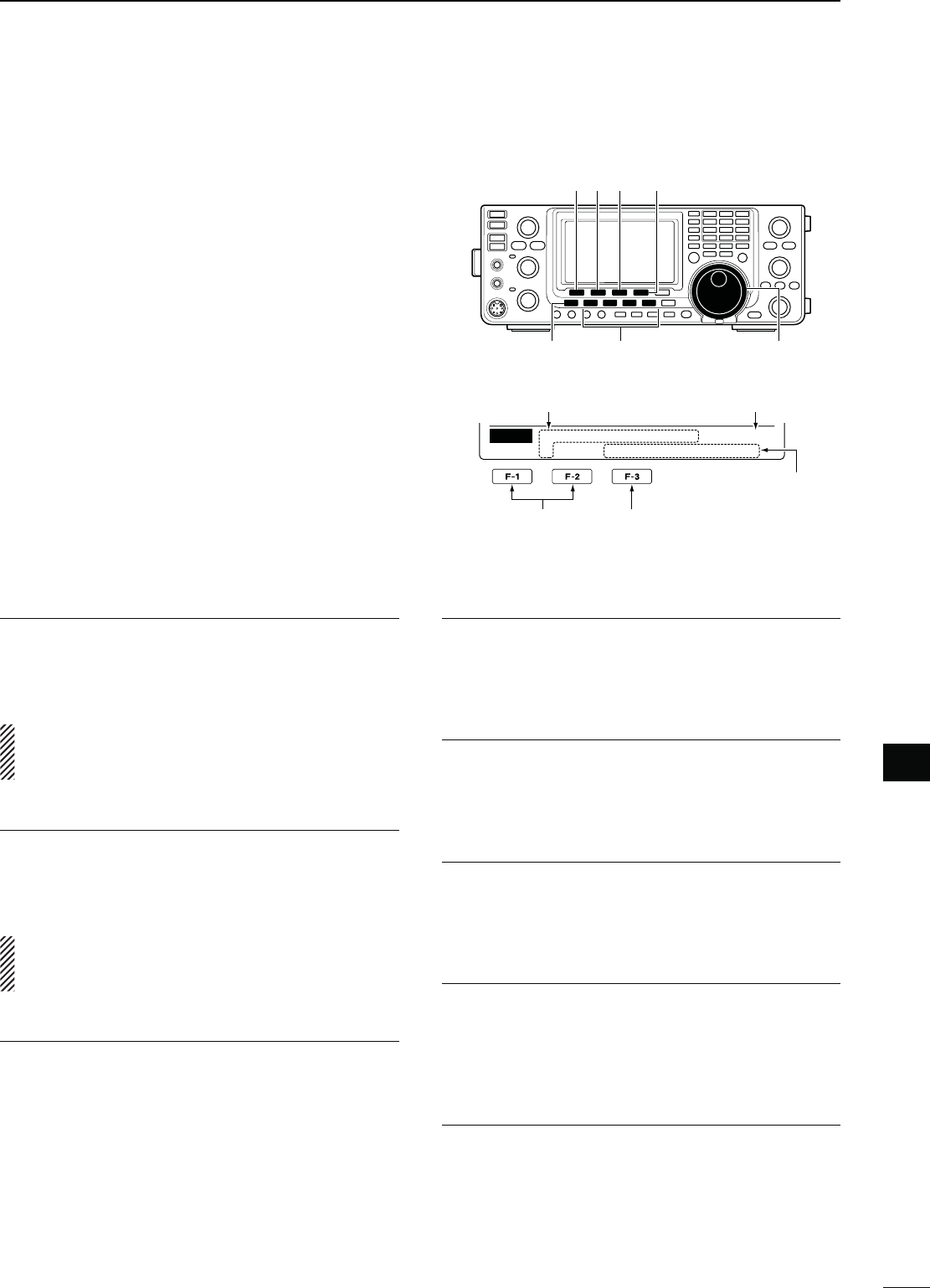
90
SET MODE
1
2
3
4
5
6
7
8
9
11
12
13
15
16
17
18
19
20
21
10
10
14
D 4HE4ONECONTROL3ETMODESETTINGS
q Push [MENU] one or more times to display the “M2”
screen (Menu 2).
w Push [TCN](F-4) to enter the Tone control Set
mode.
e Push a mode switch to select the desired operating
mode.
r Push [Y](F-1) or [Z](F-2) to select the desired
item.
s3ELECTABLEITEMSDIFFER DEPENDINGONTHE OPERATING
mode.
t Rotate [DIAL] to select the desired option.
s9OUCANSELECTTHEOPTIONFOREACHOPERATINGMODE
s(OLDDOWN;&=FORSECONDTORESETTOTHEDEFAULTSET-
ting, if desired.
y Push [MENU] to save, and exit the Set mode.
Select the item Reset to the default
setting
Mode switches
[]
[MENU]
[F-3] [TCON]
[DIAL]
[][]
Ù 1 Ú
SSB
[ – – – ] – – – –
TCON
RX HPF⁄LPF
Displays the Set mode
item name and number
Displays the option
RX HPF/LPF 1. $EFAULT/&&
-ODE33"#72449!-&-
First select the operating mode, then set the receive
audio high-pass filter to between 100 Hz and 2000 Hz
in 100 Hz steps.
./4% When the receive audio high-pass and low-
pass filters are active, “RX Bass” and “RX Treble”
items will be reset to the default value.
RX HPF/LPF 2. $EFAULT/&&
-ODE33"#72449!-&-
First select the operating mode, then set the receive
audio low-pass filter to between 500 Hz and 2400 Hz
in 100 Hz steps.
./4% When the receive audio high-pass and low-
pass filters are active, “RX Bass” and “RX Treble”
items will be reset to the default value.
28"ASS3. $EFAULT
-ODE33"!-&-
First select the operating mode, then set the receive
audio bass level to between –5 and +5.
RX Treble 4. $EFAULT
-ODE33"!-&-
First select the operating mode, then set the receive
audio treble level to between –5 and +5.
48"ASS5. $EFAULT
-ODE33"!-&-
First select the operating mode, then set the transmit
audio bass level to between –5 and +5.
TX Treble 6. $EFAULT
-ODE33"!-&-
First select the operating mode, then set the transmit
audio treble level to between –5 and +5.
4"77)$%,7. $EFAULT
-ODE33"
Set the lower cut-off frequency of the transmission
passband width for your wide setting to 100, 200, 300
or 500 Hz.
4"77)$%(8. $EFAULT
-ODE33"
Set the higher cut-off frequency of the transmission
passband width for your wide setting to 2500, 2700,
2800 or 2900 Hz.
Displays the selected
operating mode
N4ONE#ONTROL3ETMODEDESCRIPTION

91
SET MODE
10
4"7-)$,9. $EFAULT
-ODE33"
Set the lower cut-off frequency of the transmission
passband width for your mid setting to 100, 200, 300
or 500 Hz.
4"7-)$(10. $EFAULT
-ODE33"
Set the higher cut-off frequency of the transmission
passband width for your mid setting to 2500, 2700,
2800 or 2900 Hz.
4"7.!2,11. $EFAULT
-ODE33"
Set the lower cut-off frequency of the transmission
passband width for your narrow setting to 100, 200,
300 or 500 Hz.
4"7.!2(12. $EFAULT
-ODE33"
Set the higher cut-off frequency of the transmission
passband width for your narrow setting to 2500, 2700,
2800 or 2900 Hz.
N Tone Control Set mode description (Continued)
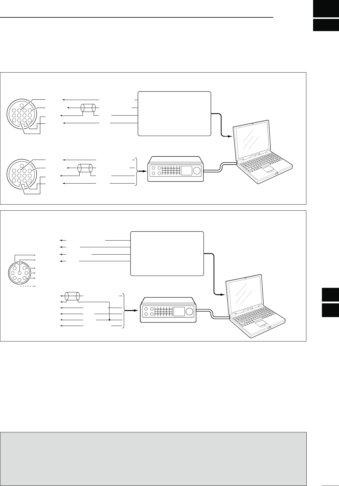
92
1
2
3
4
5
6
7
8
9
12
13
14
16
17
18
19
20
21
DATA COMMUNICATION
15
11
10
11
N#ONNECTIONS
TNC
TNC
PC
RS-232C
Rear panel view
4
8
12
123
765
9
10 11
13
RTTY OUTPUT
AUDIO INPUT
PTT
GND
FSKK
AF OUT
SEND
GND
4
8
12
123
765
9
10 11
13
RTTY OUTPUT
AUDIO INPUT
PTT
GND
FSKK
AF OUT
SEND
GND
q
u
i
t
r
y
AFSK OUTPUT
AF INPUT
PTT
GND
SQL INPUT
TNC
AUDIO OUTPUT
AF INPUT
PTT
GND
q
u
i
t
1
2
345
6
7
8
q
u
i
t*
1
y
r*
2
Rear panel view
TNC PC
RS-232C
*1
When using the VOX func-
tion, no connection is needed.
Refer to the instruction man-
ual of the external equipment.
*2 When connecting the squelch
line, consult the necessary
manual.
Connect to the serial port,
parallel port, speaker jack,
microphone jack or line IN/
OUT jack, etc.
See the instruction manual
of the application for details.
Connect to the serial port,
parallel port, speaker jack,
microphone jack or line IN/
OUT jack, etc.
See the instruction manual
of the application for details.
INFORMATION!
When the
“
USB Serial Func
” item is set to
“RTTY”
in
the Set mode (p. 89), the USB port sends RTTY decode
signal. In this case, you must connect a USB cable* between the transceiver’s USB port on the rear panel and the
PC. (p. 17)
s4HE53"DRIVERANDTHEINSTALLATIONGUIDECANBEDOWNLOADEDFROMOURWEBSITE
URL: http://www.icom.co.jp/world/index.html
* Purchase separately
D7HENCONNECTINGTO;!##=
D7HENCONNECTINGTO;-)#=
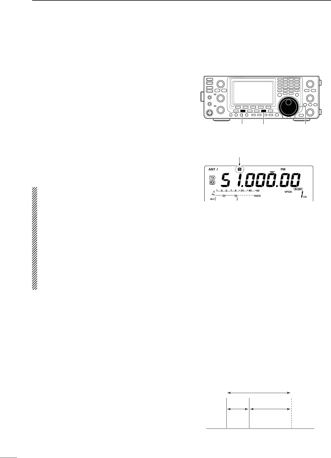
93
DATA COMMUNICATION
11
N0ACKET!&3+OPERATION
Before operating packet (AFSK), be sure to consult the
operating manual that came with your TNC.
q Connect the TNC and PC. (p. 92)
w Select the desired band. (p. 25)
e Push [SSB] or [AM/FM] to select the desired oper-
ating mode.
r Hold down the same key you pushed in step e for
1 second to select the Data mode.
t Rotate [DIAL] to select the desired frequency.
y Transmit your AFSK signals using your PC’s key-
board.
s2OTATETHE;2&072=CONTROLTOSETTHEOUTPUTPOWER
s7HILEUSINGA4.#THERELATIVESTRENGTHOFTHETRANSMIT-
ted signal is indicated on the Po meter.
s7HENOPERATINGINTHE33"DATAMODEADJUSTTHEOUT-
put power so that the ALC meter reading stays in the
ALC zone.
./4% When connecting the TNC to the ACC socket
on the rear panel, select the USB, LSB, AM and FM
data mode, or disconnect the microphone and ro-
tate the [MIC] control fully counterclockwise.
When the SSB data mode is selected, the audio
input from the [MIC] connector is automatically cut,
and the audio input from the [ACC] socket is used.
Also, when the SSB data mode is selected, the fixed
settings listed below are automatically selected;
s3PEECHCOMPRESSOR /&&
s4RANSMITBANDWIDTH -)$(Fixed to the default value;
300 Hz to 2700 Hz.)
s4XTONE"ASS
s4XTONE4REBLE
s%XAMPLELSB/LSB data mode
Mark freq.: 2125 Hz
Shift freq.: 200 Hz
2325 Hz
200 Hz 2125 Hz
Carrier point
(Displayed frequency)
When operating AFSK in the SSB mode, the displayed
frequency is the signal’s carrier point.
D&REQUENCYDISPLAYDURING!&3+OPERATION
Appears when the data mode is selected.
[AM/FM] [DIAL][SSB]
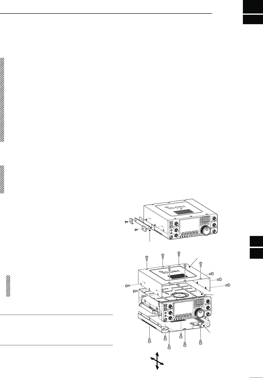
94
1
2
3
4
5
6
7
8
9
10
14
15
17
18
19
20
21
OPTION INSTALLATION
11
16
12
13
12
N/PENINGTHETRANSCEIVERSCASE
Icom strongly suggests that the customer have their
dealer or Icom distributor, for a reasonable fee, in-
stall Icom options at the time of the order. Icom un-
derstands that even the simplest of installations de-
mands the judgment of a trained Icom technician.
Therefore, Icom will not be responsible for damage
to the optional unit, or subsequent damage to the
transceiver due to user installation problems. The
option’s or the transceiver’s Warranty can be voided
in such situations, at the sole judgment of Icom.
For those customers who still wish to install their
own options, knowing the risks and possible con-
sequences, the following information is provided for
information purposes only.
The following are instructions for removing the covers
of the IC-7410.
R7!2.).' Turn OFF the power and disconnect
the DC power cable from the transceiver before per-
forming any work on the transceiver. Otherwise,
there is danger of electric shock and/or equipment
damage.
q Remove the two screws from the carrying handle
and remove it from the transceiver.
w Remove the seven screws from the top of the trans-
ceiver and the six screws from the sides, then lift up
the top cover.
e Turn the transceiver upside-down.
#!54)/..%6%2(/,$4(%5.)4"94(%
$)!,/2!.9/4(%2+./"3when you turn
the transceiver upside down. This may damage
them, or cause you to drop the transceiver.
r Remove the six screws from the bottom, and then
lift off the bottom cover.
About the leg pads
To detach the leg pads from the right side panel of
the top/bottom cover, push them out from the inside
of each cover, after completing steps q through r
above.
Carrying handle
Bottom cover
Top cover
PA shielding
plate
Top
Bottom
Rear
Front

95
OPTION INSTALLATION
12
N FL-430/FL-431 1ST IF FILTER INSTALLATION
The optional Roofing Filters, FL-430 1ST IF FILTER
(6 kHz) or FL-431 1ST IF FILTER (3 kHz) provides 6 or 3
kHz filtering to reduce interference from strong nearby
signals.
q Remove the top and bottom covers as shown on
page 94.
w Install the FL-430 or FL-431 as shown to the right.
s4HECONNECTORSONTHE)#AREMARKEDFORTHEAP-
propriate filter.
s%NSURETHE&,OR&,ISINSTALLEDCORRECTLY
e Return the top and bottom covers to the original po-
sitions.
FL-431 (3 kHz)FL-430 (6 kHz)
Top
Bottom
Rear
Front

96
1
2
3
4
5
6
7
8
9
10
11
14
15
16
18
19
20
21
MAINTENANCE
17
13
12
13
D4RANSCEIVERPOWER
02/",%- 0/33)",%#!53% SOLUTION REF.
Power does not turn ON
when the [POWER] switch is
pushed.
s4HEPOWERCABLEISIMPROPERLYCONNECTED
s!FUSEISBLOWN
s2ECONNECTTHE$#POWERCABLECORRECTLY
s#ORRECTTHECAUSETHENREPLACE THEFUSEWITH
an equivalent fuse.
( Fuses are installed in the DC power cable
and in the internal PA unit.)
p. 19
p. 99
D4RANSMITANDRECEIVE
02/",%- 0/33)",%#!53% SOLUTION REF.
No sound from the speaker. s4HEAUDIOVOLUMELEVELISTOOLOW
s4HESQUELCHISCLOSED
s4HETRANSCEIVERISINTRANSMIT
s2OTATE THE ;!&= CONTROL CLOCKWISE TO OBTAIN A
suitable listening level.
s2OTATETHE;2&31,=CONTROLTOOCLOCKPO-
sition to open the squelch.
s0USH ;42!.3-)4= TO RECEIVE OR CHECK THE
SEND line of an external unit, if connected.
p. 31
p. 32
p. 34
Sensitivity is too low, and only
strong signals are audible.
s4HEANTENNAISNOTCONNECTEDPROPERLY
s4HEANTENNAFORANOTHERBANDISSELECTED
s4HEANTENNAISNOTPROPERLYTUNED
s4HEATTENUATORISTURNED/.
s2ECONNECTTOTHEANTENNACONNECTOR
s3ELECT AN ANTENNA SUITABLE FOR THE OPERATING
frequency.
s(OLDDOWN;45.%2=FORSECONDTOMANUALLY
tune the antenna.
s0USH ;0!-0!44= TO SELECT TO TURN /&& THE
attenuator.
—
p. 82
p. 83
p. 55
Received audio is unclear or
distorted.
s4HEOPERATINGMODEISNOTMATCHED
s4HE0ASSBAND4UNINGFUNCTIONISTURNED/.
s4HE.OISE"LANKERFUNCTIONISTURNED/.WHEN
receiving a strong signal.
s0REAMPLIlERISTURNED/.
s4HE .OISE 2EDUCTION FUNCTION IS TURNED /.
and the [NR] control is too far clockwise.
s3ELECTASUITABLEOPERATINGMODE
s(OLD DOWN ;0"4#,2= FOR SECOND TO RESET
the function.
s0USH;."=TOTURN/&&THEFUNCTION
s0USH;0!-0!44=ONCEORTWICETOTURN/&&
the function.
s3ETTHE;.2=CONTROLFORMAXIMUMREADABILITY
p. 31
p. 59
p. 60
p. 55
p. 61
;!.4s-%4%2= DOES NOT FUNC-
tion
s4HE!NTENNA3WITCHFUNCTIONISSETTOh/&&v s3ET THE !NTENNA 3WITCH FUNCTION TO h!UTOv OR
“Manual” in the Set mode.
p. 87
Transmitting is impossible. s4HE OPERATING FREQUENCY IS OUTSIDE THE SE-
lected ham band.
s3ET THE FREQUENCY TO BE WITHIN THE SELECTED
ham band.
p. 26
Output power is too low. s4HE ;2& 072= CONTROL IS SET TOO FAR COUNTER-
clockwise.
s4HE ;-)#= CONTROL IS SET TOO FAR COUNTERCLOCK-
wise.
s4HEANTENNAFORANOTHERBANDISSELECTED
s4HEANTENNAISNOTPROPERLYTUNED
s2OTATETHE;2&072=CONTROLCLOCKWISE
s3ETTHE;-)#=CONTROLTOASUITABLEPOSITION
s3ELECT AN ANTENNA SUITABLE FOR THE OPERATING
frequency.
s(OLDDOWN;45.%2=FORSECONDTOMANUALLY
tune the antenna.
p. 34
p. 34
p. 82
p. 83
No contact can be made with
another station.
s4HE2)4OR∂TX function is turned ON.
s4HE3PLITFUNCTIONISTURNED/.
s0USH;2)4=OR;∂TX] to turn OFF the function.
s0USH;30,)4=TOTURN/&&THEFUNCTION
pp. 53, 65
p. 66
Transmit signal is unclear or
distorted.
s4HE;-)#=CONTROLISSETTOOFARCLOCKWISE s3ETTHE;-)#=CONTROLTOASUITABLEPOSITION p. 34
Repeater cannot be accessed. s4HE3PLITFUNCTIONISNOTTURNED/.
s4HE PROGRAMMED SUBAUDIBLE TONE FREQUENCY
is wrong.
s0USH;30,)4=TOTURN/.THEFUNCTION
s2ESETTHEFREQUENCYUSINGTHE3ETMODE
p. 66
p. 52
N4ROUBLESHOOTING
The following chart is designed to help you correct
problems which are not equipment malfunctions.
If you are unable to locate the cause of a problem,
or solve it through the use of this chart, contact your
nearest Icom Dealer or Service Center.
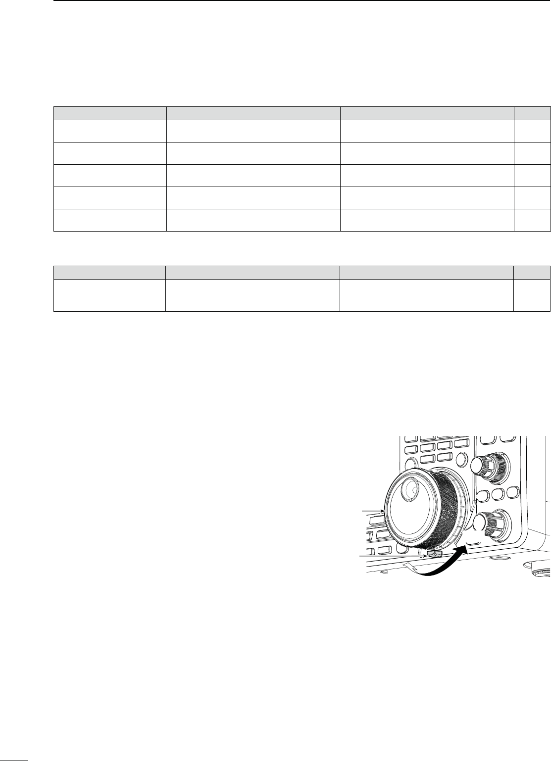
97
13 MAINTENANCE
N Troubleshooting (continued)
D3CANNING
02/",%- 0/33)",%#!53% SOLUTION REF.
A programmed scan does not
stop.
s3QUELCHISOPEN s3ET THE ;2&31,= CONTROL TO THE THRESHOLD
point.
p. 32
A programmed scan does not
start.
s
The same frequencies are programmed into the
Scan Edge Memory channels
“P1” and “P2.”
s0ROGRAM DIFFERENT FREQUENCIES INTO
the Scan
Edge Memory channels
“P1” and “P2.”
p. 70
A memory scan does not start. s4WOORMOREMEMORYCHANNELSHAVENOTBEEN
programmed.
s0ROGRAMMORETHANTWOMEMORYCHANNELS p. 70
A select memory scan does
not start.
s4WOORMOREMEMORYCHANNELSHAVENOTBEEN
designated as select channels.
s$ESIGNATEMORETHANTWOMEMORYCHANNELSAS
select channels for the scan.
p. 80
A ∂F scan does not start. s4HE CENTER FREQUENCY FOR THE ∂F scan is not
programmed.
s0ROGRAMTHECENTERFREQUENCYFORTHE∂F scan. p. 81
D$ISPLAY
02/",%- 0/33)",%#!53% SOLUTION REF.
The displayed frequency does
not change properly.
s4HE$IAL,OCKFUNCTIONISTURNED/.
s4HE3ETMODESCREENISSELECTED
s4HEINTERNAL#05HASMALFUNCTIONED
s0USH;,/#+=TURN/&&THEFUNCTION
s0USH[MENU] to exit the Set Mode.
s2ESETTHE#05
p. 61
p. 85
p. 100
The tuning tension of [DIAL] may be adjusted to suit
your preference.
The tension adjustment is located on the bottom side
of the front panel. See the figure to the right.
Slide the tension adjustment to a comfortable level
while turning the dial continuously and evenly in one
direction. DIAL
Tuning tension
adjustment
Light
Firm
N$IALTUNINGTENSIONADJUSTMENT
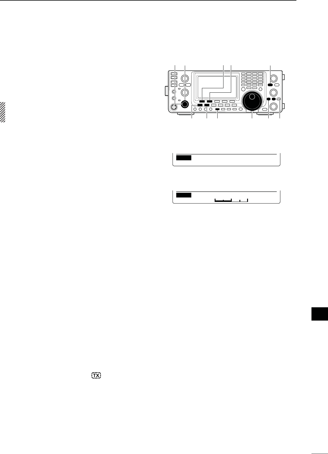
98
13
MAINTENANCE
1
2
3
4
5
6
7
8
9
10
11
12
13
14
15
16
17
18
19
20
21
N&REQUENCYCALIBRATIONAPPROXIMATE
[PBT-CLR] [][]
[][][][]
[][]
[DIAL]
Ù 47 ÚOFF
SET Calibration Marker
Ù48 Ú50%
SET REF Adjust
s#ALIBRATIONMARKERITEM
s2%&!DJUSTITEM
A very accurate frequency counter is required to cali-
brate the frequency of the transceiver. However, a
rough check may be performed by receiving radio sta-
tion WWV, WWVH, or other standard frequency sig-
nals.
#!54)/. The IC-7410 has been thoroughly ad-
justed and tested at the factory before being
shipped. You should not have to re-calibrate it.
q Push [SSB] once or twice to select the USB mode.
w Push [PBT-CLR] for 1 second to clear the PBT set-
tings and make sure that the RIT/∂TX function is
turned OFF.
e Set the frequency to the standard frequency station
minus 1 kHz.
s
When receiving WWV or WWVH (at 15.000.00 MHz) as
a standard frequency, set the operating frequency for
14.999.00 MHz.
s/THERSTANDARDFREQUENCIESCANALSOBEUSED
r
Hold down
[MENU] for 1 second to enter the Set
mode.
t Push [Y](F-1) or [Z](F-2) to select “Calibration
Marker.”
y Rotate [DIAL] to turn ON the calibration marker.
s!SIDETONEMAYBEHEARD
u Push [Z](F-2) to select “REF Adjust.”
i Rotate [DIAL] to adjust for a zero beat with the re-
ceived standard signal.
s:EROBEATMEANSTHATTWOSIGNALSAREEXACTLYTHESAME
frequency, resulting in a single tone being heard.
o Push [Y](F-1) to select “Calibration Marker.”
!0 Rotate [DIAL] to turn OFF the calibration marker.
!1 Push [MENU] to save, and exit the Set mode.
The IC-7410 2-step protection function monitors the
power amplifier temperature and activates when the
temperature becomes extremely high.
s2EDUCEDPOWERTRANSMISSION
Halves the transmit output power.
“LMT” appears above the TX icon “ .” (p. 11)
s4RANSMISSIONINHIBIT
Deactivates the transmitter.
Even if you push [PTT] or [TRANSMIT], the TX indica-
tor does not light.
When the protector is activated, operate in only the
stand-by or receive mode until the power amplifier
cools down.
./4%$/./4turn OFF the transceiver power
when the protector is ON, or the cooling fan will not
function, and delay cooling the transceiver.
N!BOUTPROTECTIONDISPLAYS
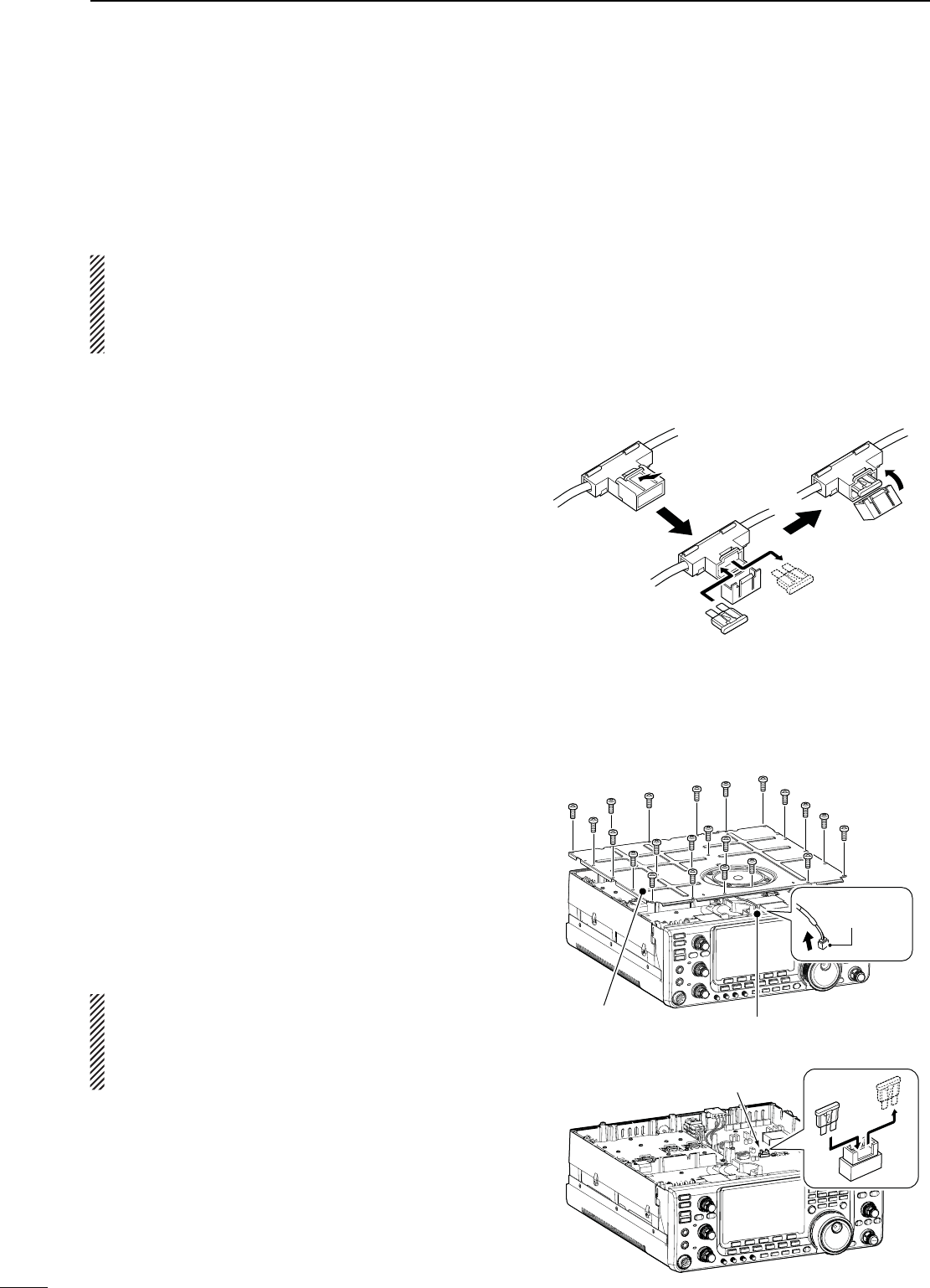
99
13 MAINTENANCE
D#IRCUITRYFUSEREPLACEMENT
Except for the power amplifier, the 13.8 V DC from the
DC power cable is applied to all units in the IC-7410,
through the circuitry fuse. This fuse is located in the
PA unit.
q Remove the top cover. (p. 94)
w Remove the 22 screws, then remove the PA shield-
ing plate as shown to the right.
e Remove the speaker cable from the connector on
the PA unit as shown to the right.
r Replace the circuitry fuse as shown in the diagram
to the right.
t Replace the speaker cable, PA shielding plate, top
cover and screws to their original position.
R7!2.).'
DO NOT pull the speaker cable
when removing the PA shielding plate, or DO NOT
put the speaker cable under the PA shielding plate
when replacing it. This could damage the trans-
ceiver.
ATC 30 A fuse
N&USEREPLACEMENT
If a fuse blows, or the transceiver stops functioning,
find the source of the problem, and repair it. Then re-
place the damaged fuse with a new, adequately rated
fuse.
#!54)/. Turn OFF the power and disconnect the
DC power cable from the transceiver before per-
forming any work on the transceiver. Otherwise,
there is danger of electric shock, equipment dam-
age and/or fire injury,
The IC-7410 has two fuse types installed for trans-
ceiver protection.
s$#POWERCABLEFUSES .............................. ATC 30 A
s#IRCUITRYFUSE .............................................. ATC 5 A
D$#POWERCABLEFUSEREPLACEMENT
Refer to the figure illustrated to the right for the DC
power cable fuse replacement.
Speaker cable
PA shielding plate
ATC 5 A fuse
Connector
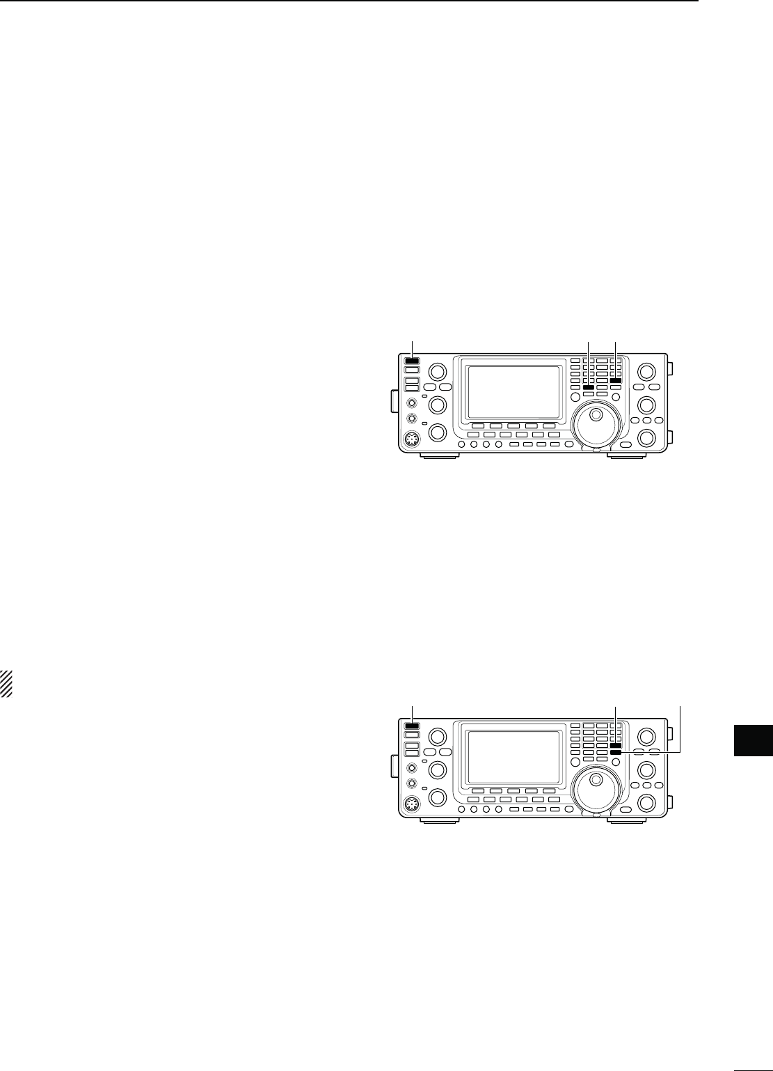
100
13
MAINTENANCE
1
2
3
4
5
6
7
8
9
10
11
12
13
14
15
16
17
18
19
20
21
N2ESETTINGTHE#05
D0ARTIALRESET
If you want to reset the operating parameters to their
default values (VFO frequency, VFO settings, menu
group’s contents) without clearing certain data as de-
scribed below, a partial reset can be performed.
The following data will not be cleared when doing a
Partial reset:
s-EMORYCONTENTS
s-EMORYKEYERCONTENTS
s0ROGRAMMEDUSERBANDEDGEFREQUENCIES
s2%&!DJUST2EFERENCEFREQUENCYSETTING
q First, turn OFF the transceiver power.
w While holding down [F-INP ENT] and [VFO/MEMO],
push [POWER] to turn ON the power.
s$URING STARTUP THE TRANSCEIVER DISPLAYS h0!24)!,
RESET,” then the initial VFO frequencies when reset-
ting is complete.
s)FYOUOPERATETHETRANSCEIVERBEFOREh0!24)!,2%3%4v
disappears, the resetting will be cancelled.
e
If desired, edit the Set mode settings after resetting.
D!LLRESET
The display may occasionally display erroneous infor-
mation (e.g. when first applying power). This may be
caused externally by static electricity or by other fac-
tors.
If this problem occurs, turn OFF the power. After wait-
ing a few seconds, turn ON the power again. If the
problem persists, perform the following procedure.
./4%Resetting the CPU CLEARS all programmed
contents and returns them to their default settings.
q First, turn OFF the transceiver power.
w While holding down [F-INP ENT] and [M-CLR],
push [POWER] to turn ON the power.
s$URINGSTARTUPTHETRANSCEIVERDISPLAYSh!,,#,%!2v
then when resetting is complete, then displays the initial
VFO frequencies.
s)FYOUOPERATETHETRANSCEIVERBEFOREh!,,#,%!2vDIS-
appears, the resetting will be cancelled.
e
If desired, edit the Set mode settings after resetting.
[POWER] [F-INP ENT] [M-CLR]
[POWER] [F-INP ENT] [VFO/MEMO]
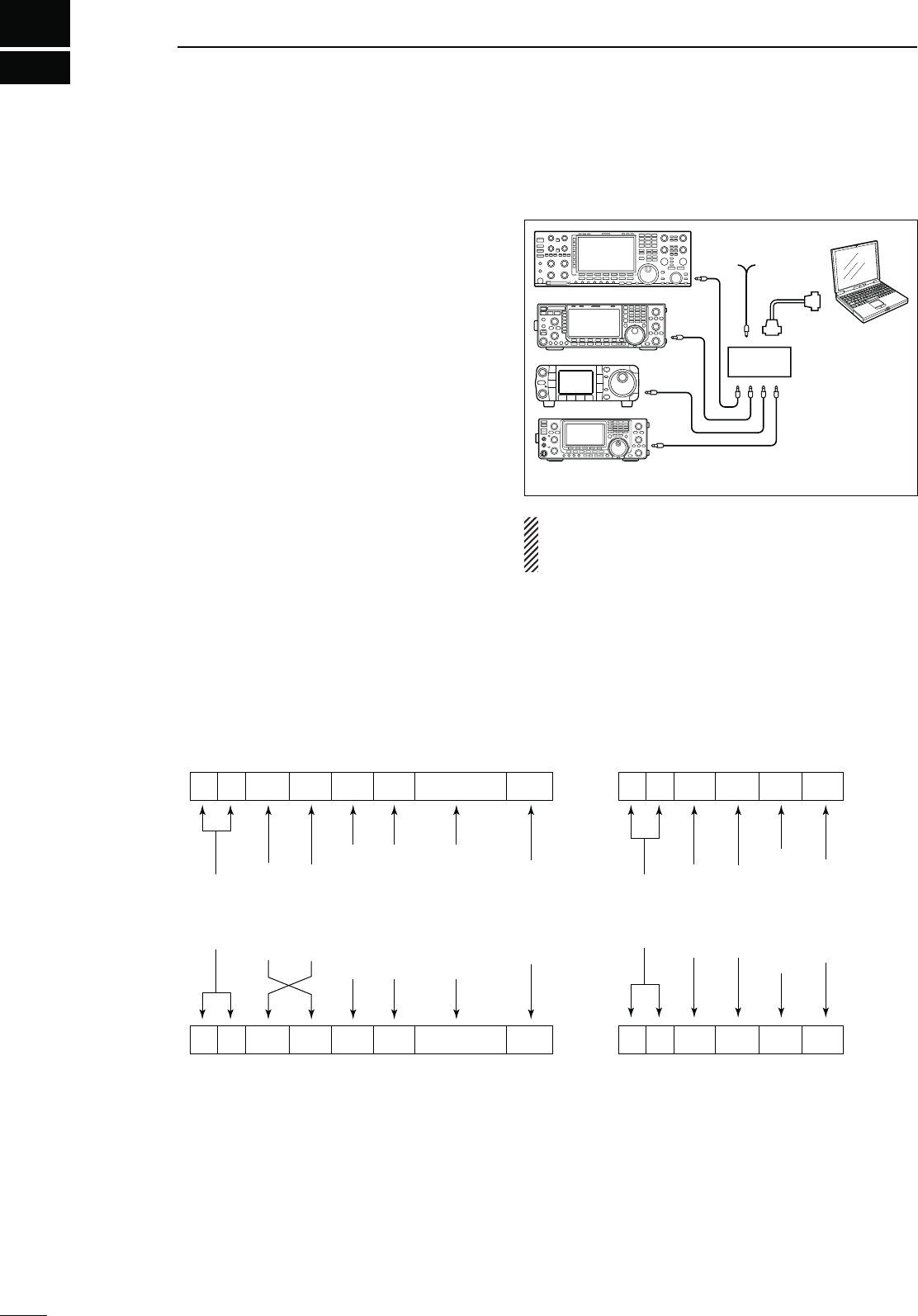
101
CONTROL COMMAND
14
N2EMOTEJACK#)6INFORMATION
Controller to IC-7410
FE FE 80 E0 Cn Sc Data area FD
Preamble
code (fixed)
Transceiver’s
default address
Controller’s
default address
Command number
(see the command table)
Sub command number
(see the command table)
BCD code data such as
for frequency, memory
number entry
(see the data content description)
End of message
code (fixed)
OK message to controller
FE FE E0 80 FB FD
FE FE E0 80 FA FD
Preamble
code (fixed)
Controller’s
default address
Transceiver’s
default address
OK code
(fixed)
End of message
code (fixed)
NG message to controller
NG code
(fixed)
IC-7410 to controller
qwert y u
FE FE E0 80 Cn Sc Data area FD
qwert y u
D#)6CONNECTIONEXAMPLE
The transceiver can be connected through an optional
CT-17 CI-V LEVEL CONVERTER to a PC equipped with an
RS-232C port. The Icom Communications Interface-V
(CI-V) controls the transceiver.
Up to 4 Icom CI-V transceivers or receivers can be
connected to the PC. See p. 89 for setting the CI-V
condition using the Set mode.
D$ATAFORMAT
The CI-V system can be operated using the following
data formats. Data formats differ, depending on com-
mand numbers. A data area or sub command is added
to some commands.
IC-7410
9−15V DC
PC
ct-17
mini-plug cable
RS-232C
cable
When the transceiver is connected to a PC with a
USB cable (purchased separately), the optional
CT-17 is not required.

102
CONTROL COMMAND
1
2
3
4
5
6
7
8
9
10
11
12
13
15
16
17
19
20
21
14
18
14
D#OMMANDTABLE
#MD 3UBCMD Data $ESCRIPTION
00 see p. 106 Send operating frequency for transceive
01 see p. 106 Send operating mode for transceive
02 see p. 106 Read band edge frequencies
03 see p. 106 Read operating frequency
04 see p. 106 Read operating mode
05 see p. 106 Send operating frequency
06 see p. 106 Send operating mode
07 Select VFO mode
00 Select VFO A
01 Select VFO B
A0 Equalize VFO A and VFO B
B0 Exchange VFO A and VFO B
08 Select Memory mode
0001 to
0101
Select memory channel
( 0001=M-CH01 to 0099=M-CH99,
0100=P1, 0101=P2)
09 Memory write
0A Memory copy to VFO
0B Memory clear
0E 00 Scan stop
01 Programmed/memory scan start
02 Programmed scan start
03 ∂F scan start
12 Fine programmed scan start
13 Fine ∂F scan start
22 Memory scan start
23 Select memory scan start
A1 Set ∂F scan span ±5 kHz
A2 Set ∂F scan span ±10 kHz
A3 Set ∂F scan span ±20 kHz
A4 Set ∂F scan span ±50 kHz
A5 Set ∂F scan span ±100 kHz
A6 Set ∂F scan span ±500 kHz
A7 Set ∂F scan span ±1 MHz
B0 Set as non-select channel
B1 Set as select channel
D0 Set scan resume OFF
D3 Set scan resume ON
0F Read Split function
(00=OFF, 01=ON)
00 Set the Split function OFF
01 Set the Split function ON
10 00 Send/read the tuning step 10 Hz (1 Hz)
01 Send/read the tuning step 100 Hz
02 Send/read the tuning step 1 kHz
03 Send/read the tuning step 5 kHz
04 Send/read the tuning step 9 kHz
05 Send/read the tuning step 10 kHz
06 Send/read the tuning step 12.5 kHz
07 Send/read the tuning step 20 kHz
08 Send/read the tuning step 25 kHz
11 00 Send/read attenuator OFF
20 Send/read 20 dB attenuator
12 00 Send/read ANT1 selection
00 Send/read ANT2 selection
13 00 Announce operating frequency, operating
mode and S-meter level with voice synthe-
sizer
01
Announce operating frequency and S-meter
level with voice synthesizer
02 Announce operating mode with voice syn-
thesizer
#MD 3UBCMD Data $ESCRIPTION
14 01 0000 to
0255
Send/read [AF] position
(0000=max. CCW, 0255=max. CW)
02 0000 to
0255
Send/read [RF] position
(0000=max. CCW, 0255=11 o’clock)
03 0000 to
0255
Send/read [SQL] position
(0000=11 o’clock, 0255=max. CW)
06 0000 to
0255
Send/read [NR] position
TO
07 0000 to
0255
Send/read inner [TWIN PBT] position
( 0000=max. CCW, 0128=center,
0255=max. CW)
08 0000 to
0255
Send/read outer [TWIN PBT] position
( 0000=max. CCW, 0128=center,
0255=max. CW)
09 0000 to
0255
Send/read [CW PITCH] position
( 0000=300 Hz, 0128=600 Hz,
0255=900 Hz; 5 Hz steps)
0A 0000 to
0255
Send/read [RF PWR] position
(0000=max. CCW to 0255=max. CW)
0B 0000 to
0255
Send/read [MIC] position
(0000=max. CCW to 0255=max. CW)
0C 0000 to
0255
Send/read [KEY SPEED] position
(0000=max. CCW to 0255=max. CW)
0D 0000 to
0255
Send/read [NOTCH] position
( 0000=max. CCW, 0128=center,
0255=max. CW)
0E 0000 to
0255
Send/read [COMP] position
(0000=max. CCW to 0255=max. CW)
0F 0000 to
0255
Send/read [BK-IN DELAY] position
(0000=max. CCW to 0255=max. CW)
12 0000 to
0255
Send/read [NB] position
(0000=max. CCW to 0255=max. CW)
15 0000 to
0255
Send/read [MONI GAIN] position
(0000=max. CCW to 0255=max. CW)
16 0000 to
0255
Send/read VOX gain
TO
17 0000 to
0255
Send/read Anti VOX gain
TO
18 0000 to
0255
Send/read CONTRAST level
TO
19 0000 to
0255
Send/read BRIGHT level
TO
15 01 00 Read squelch state (squelch close)
01 Read squelch state (squelch open)
02 0000 to
0255
Read S-meter level
(0000=S0, 0120=S9, 0241=S9+60 dB)
11 0000 to
0255
Read RF power meter
12 0000 to
0255
Read SWR meter
(
0000=SWR1.0, 0041=SWR1.5,
0081=SWR2.0, 0120=SWR3.0)
13 0000 to
0255
Read ALC meter
(0000=Min., 0120=Max.)
14 0000 to
0255
Read COMP meter
(0000=0 dB, 0120=15 dB, 0240=30 dB)
16 02 00 Send/read Preamp OFF
01 Send/read Preamp 1 ON
02 Send/read Preamp 2 ON
12 01 Send/read AGC FAST
02 Send/read AGC MID
03 Send/read AGC SLOW
22 00 Send/read Noise Blanker OFF
01 Send/read Noise Blanker ON
40 00 Send/read Noise Reduction OFF
01 Send/read Noise Reduction ON
41 00 Send/read Auto Notch function OFF
01 Send/read Auto Notch function ON

103
CONTROL COMMAND
14
D Command table (continued)
#MD 3UBCMD Data $ESCRIPTION
16 42 00 Send/read Repeater tone OFF
01 Send/read Repeater tone ON
43 00 Send/read Tone squelch OFF
01 Send/read Tone squelch ON
44 00 Send/read Speech Compressor OFF
01 Send/read Speech Compressor ON
45 00 Send/read Monitor function OFF
01 Send/read Monitor function ON
46 00 Send/read VOX function OFF
01 Send/read VOX function ON
47 00 Send/read BK-IN function OFF
01 Send/read Semi BK-IN function ON
02 Send/read Fill BK-IN function ON
48 00 Send/read Manual Notch function OFF
01 Send/read Manual Notch function ON
4C 00 Send/read VSC function OFF
01 Send/read VSC function ON
4F 00 Send/read Twin Peak Filter OFF
01 Send/read Twin Peak Filter ON
50 00 Send/read Dial Lock function OFF
01 Send/read Dial Lock function ON
55 00 Send/read 1st IF filter 15 kHz
01 Send/read 1st IF filter 6 kHz
02 Send/read 1st IF filter 3 kHz
56 00 Send/read DSP filter type SHARP
01 Send/read DSP filter type SOFT
57 00 Send/read manual notch width WIDE
01 Send/read manual notch width MID
02 Send/read manual notch width NAR
58 00 Send/read SSB transmit bandwidth WIDE
01 Send/read SSB transmit bandwidth MID
02 Send/read SSB transmit bandwidth NAR
17 see p. 107 Send CW messages
19 00 Read the transceiver ID
1A 00 see p. 108 Send/read memory contents
01 see p. 106 Send/read band stacking register contents
02 see p. 107 Send/read memory keyer contents
03 00 to 49 Send/read the selected filter width
( AM: 00=200 Hz to 49=10 kHz; other than
AM modes: 00=50 Hz to 40/31=3600
Hz/2700 Hz)
04 00 to 13 Send/read the selected AGC time constant
( 00=OFF, AM: 01=0.3 sec. to 13=8.0 sec.;
other than AM modes: 01=0.1 sec. to
13=6.0 sec.)
05 0001 0000 to
0255
Send/read LCD unit backlight brightness
level
DARKTOBRIGHT
0002 0000 to
0255
Send/read LCD backlight brightness level
DARKTOBRIGHT
0003 0000 to
0255
Send/read beep level
TO
0004 00 Send/read beep level limit OFF
01 Send/read beep level limit ON
0005 00 Send/read confirmation beep OFF
01 Send/read confirmation beep ON
0006 00 Send/read band edge beep OFF
01 Send/read band edge beep ON
(Beep sounds with a default band)
02 Send/read band edge beep with user set-
ting ON
03 Send/read band edge beep with user set-
ting/TX limit ON
0007 0050 to
0200
Send/read beep audio frequency
(0050=500 Hz to 0200=2000 Hz)
#MD 3UBCMD Data $ESCRIPTION
1A 05 0008 00 Send/read Auto selection for [RF/SQL]
01 Send/read SQL selection for [RF/SQL]
02 Send/read RF+SQL selection for [RF/SQL]
0009 00 Send/read Meter Peak Hold function OFF
01 Send/read Meter Peak Hold function ON
0010 00 Send/read Time-Out Timer (CI-V) OFF
01 Send/read 3 min. Time-Out Timer (CI-V)
02 Send/read 5 min. Time-Out Timer (CI-V)
03 Send/read 10 min. Time-Out Timer (CI-V)
04 Send/read 20 min. Time-Out Timer (CI-V)
05 Send/read 30 min. Time-Out Timer (CI-V)
0011 00 Send/read Quick Split function OFF
01 Send/read Quick Split function ON
0012 see p. 107 Send/read FM Split offset frequency (HF)
0013 see p. 107 Send/read FM Split offset frequency
(50 MHz)
0014 00 Send/read Split Lock function OFF
01 Send/read Split Lock function ON
0015 00 Send/read Tuner Auto Start OFF
01 Send/read Tuner Auto Start ON
0016 00 Send/read PTT Tune OFF
01 Send/read PTT Tune ON
0017 00 Send/read antenna selection OFF
01 Send/read manual antenna selection
02 Send/read auto antenna selection
0018 0000 to
0255
Send/read voice synthesizer level
TO
0019 00 Send/read English selection for voice syn-
thesizer speech language
01 Send/read Japanese selection for voice
synthesizer speech language
0020 00 Send/read speech speed slow
01 Send/read speech speed fast
0021 00 Send/read S-meter level announcement
OFF
01 Send/read S-meter level announcement
ON
0022 00 Send/read operating mode announcement
(after pushing mode switch) OFF
01 Send/read operating mode announcement
(after pushing mode switch) ON
0023 00 Send/read number of memo pad channels
5
01 Send/read number of memo pad channels
10
0024 00 Send/read auto TS for [DIAL] OFF
01 Send/read auto TS for [DIAL] Low
02 Send/read auto TS for [DIAL] High
0025 00 Send/read Low selection for microphone
Up/Down speed
01 Send/read High selection for microphone
Up/Down speed
0026 00 Send/read Quick RIT/∂TX clear OFF
01 Send/read Quick RIT/∂TX clear ON
0027 00 Send/read Auto Notch selection for SSB
01
Send/read Manual Notch selection for SSB
02 Send/read Auto/Manual Notch selection
for SSB
0028 00 Send/read Auto Notch selection for AM
01 Send/read Manual Notch selection for AM
02 Send/read Auto/Manual Notch selection
for AM
0029 00 Send/read manual notch filter width pop-
up OFF
01 Send/read manual notch filter width pop-
up ON

104
CONTROL COMMAND
1
2
3
4
5
6
7
8
9
10
11
12
13
15
16
17
19
20
21
14
18
14
#MD 3UBCMD Data $ESCRIPTION
1A 05 0030 00 Send/read PBT shifting value pop-up OFF
01 Send/read PBT shifting value pop-up ON
0031 00 Send/read IF filter width pop-up OFF
01 Send/read IF filter width pop-up ON
0032 00 Send/read SSB/CW Synchronous Tuning
function OFF
01 Send/read SSB/CW Synchronous Tuning
function ON
0033 00 Send/read LSB selection for CW normal
side
01 Send/read USB selection for CW normal
side
0034 00 Send/read KEYER-Root selection for
keyer 1st menu
01 Send/read KEYER-SEND selection for
keyer 1st menu
0035 00 Send/read external keypad OFF
01 Send/read KEYER SEND selection for the
external keypad
0036 00 Send/read USB audio squelch OFF
(OPEN)
01 Send/read USB audio squelch ON
0037 0000 to
0255
Send/read USB modulation level
TO
0038 00 Send/read MIC selection for the modula-
tion input during DATA mode OFF
01 Send/read ACC selection for the modula-
tion input during DATA mode OFF
02 Send/read MIC+ACC selection for the
modulation input during DATA mode OFF
03 Send/read USB selection for the modula-
tion input during DATA mode OFF
0039 00 Send/read MIC selection for the modula-
tion input during DATA mode operation
01 Send/read ACC selection for the modula-
tion input during DATA mode operation
02 Send/read MIC+ACC selection for the
modulation input during DATA mode op-
eration
03 Send/read USB selection for the modula-
tion input during DATA mode operation
0040 00 Send/read CI-V transceive OFF
01 Send/read CI-V transceive ON
0041 00 Send/read CI-V selection for “USB” (COM
port) function
01 Send/read RTTY selection for “USB”
(COM port) function
0042 00 Send/read 300 bps selection for RTTY De-
code Baud rate
01 Send/read 1200 bps selection for RTTY
Decode Baud rate
02 Send/read 4800 bps selection for RTTY
Decode Baud rate
03 Send/read 9600 bps selection for RTTY
Decode Baud rate
04 Send/read 19200 bps selection for RTTY
Decode Baud rate
0043 00 Send/read Calibration marker OFF
01 Send/read Calibration marker ON
0044 0000 to
0255
Send/read reference frequency
TO
0045 see p. 107 Send/read SSB RX HPF/LPF setting
0046 00 to 10 Send/read SSB RX Tone (Bass) level
(00=–5 to 10=+5)
0047 00 to 10 Send/read SSB RX Tone (Treble) level
(00=–5 to 10=+5)
#MD 3UBCMD Data $ESCRIPTION
1A 05 0048 00 to 10 Send/read SSB TX Tone (Bass) level
(00=–5 to 10=+5)
0049 00 to 10 Send/read SSB TX Tone (Treble) level
(00=–5 to 10=+5)
0050 see p. 107 Send/read SSB TX bandwidth for WIDE
0051 see p. 107 Send/read SSB TX bandwidth for MID
0052 see p. 107 Send/read SSB TX bandwidth for NAR-
ROW
0053 see p. 107 Send/read AM RX HPF/LPF setting
0054 00 to 10 Send/read AM RX tone (Bass) level
(00=–5 to 10=+5)
0055 00 to 10 Send/read AM RX Tone (Treble) level
(00=–5 to 10=+5)
0056 00 to 10 Send/read AM TX tone (Bass) level
(00=–5 to 10=+5)
0057 00 to 10 Send/read AM TX Tone (Treble) level
(00=–5 to 10=+5)
0058 see p. 107 Send/read FM RX HPF/LPF setting
0059 00 to 10 Send/read FM RX tone (Bass) level
(00=–5 to 10=+5)
0060 00 to 10 Send/read FM RX Tone (Treble) level
(00=–5 to 10=+5)
0061 00 to 10 Send/read FM TX tone (Bass) level
(00=–5 to 10=+5)
0062 00 to 10 Send/read FM TX Tone (Treble) level
(00=–5 to 10=+5)
0063 see p. 107 Send/read CW RX HPF/LPF setting
0064 see p. 107 Send/read RTTY RX HPF/LPF setting
0065 00 Send/read Normal selection for contest
number style
01 Send/read “190 㸢ANO” selection for con-
test number style
02 Send/read “190 㸢ANT” selection for con-
test number style
03 Send/read “90 㸢NO” selection for contest
number style
04 Send/read “90 㸢NT” selection for contest
number style
0066 01 Send/read M1 selection for count up trig-
ger channel
02 Send/read M2 selection for count up trig-
ger channel
03 Send/read M3 selection for count up trig-
ger channel
04 Send/read M4 selection for count up trig-
ger channel
0067 0001 to
9999
Send/read present number
(0001=1 to 9999=9999)
0068 0000 to
0255
Send/read CW sidetone gain
TO
0069 00 Send/read CW sidetone gain limit OFF
01 Send/read CW sidetone gain limit ON
0070 01 to 60 Send/read CW keyer repeat time
(01=1 sec. to 60=60 sec.)
0071 00 Send/read Normal selection for message
display
01 Send/read Message selection for message
display
0072 28 to 45 Send/read CW keyer dot/dash ratio
(28=1:1:2.8 to 45=1:1:4.5)
0073 00 Send/read 2 msec. selection for Rise time
01 Send/read 4 msec. selection for Rise time
02 Send/read 6 msec. selection for Rise time
03 Send/read 8 msec. selection for Rise time

105
CONTROL COMMAND
14
D Command table (continued)
#MD 3UBCMD Data $ESCRIPTION
1A 05 0074 00 Send/read Normal selection for paddle po-
larity
01 Send/read Reverse selection for paddle
polarity
0075 00 Send/read Straight selection for keyer type
01 Send/read BUG-Key selection for keyer
type
02 Send/read ELEC-Key selection for keyer
type
0076 00 Send/read Mic. up/down keyer OFF
01 Send/read Mic. up/down keyer ON
0077 00 Send/read 1275 Hz selection for RTTY
mark frequency
01 Send/read 1615 Hz selection for RTTY
mark frequency
02 Send/read 2125 Hz selection for RTTY
mark frequency
0078 00 Send/read 170 Hz selection for RTTY shift
width
01 Send/read 200 Hz selection for RTTY shift
width
02 Send/read 425 Hz selection for RTTY shift
width
0079 00 Send/read Normal selection for RTTY key-
ing polarity
01 Send/read Reverse selection for RTTY
keying polarity
0080 00 Send/read RTTY decode USOS OFF
01 Send/read RTTY decode USOS ON
0081 00 Send/read “CR,LF,CR+LF” selection for
RTTY decode new line code
01 Send/read “CR+LF” selection for RTTY
decode new line code
0082 00 Send/read 2 lines selection for number of
RTTY decoder line
01 Send/read 3 lines selection for number of
RTTY decoder line
0083 00 Send/read Scan speed low
01 Send/read Scan speed high
0084 00 Send/read Scan resume OFF
01 Send/read Scan resume ON
0085 00 to 09 Send/read NB depth
(00=1 to 09=10)
0086 0000 to
0255
Send/read NB width
(0000=1 to 0255=100)
0087 0000 to
0255
Send/read VOX gain
TO
0088 0000 to
0255
Send/read ANTI-VOX gain
TO
0089 00 to 20 Send/read VOX delay time
(00=0.0 sec. to 20=2.0 sec.)
0090 00 Send/read VOX voice delay OFF
01 Send/read Short selection for VOX voice
delay
02 Send/read Mid selection for VOX voice
delay
03 Send/read Long selection for VOX voice
delay
06 see p. 108 Send/read DATA mode selection
#MD 3UBCMD Data $ESCRIPTION
1B 00 see p. 108 Send/read Repeater tone frequency
01 see p. 108 Send/read Tone squelch frequency
1C 00 00 Send/read Transceiver’s status (RX)
01 Send/read Transceiver’s status (TX)
01 00 Send/read Antenna tuner OFF (through)
01 Send/read Antenna tuner ON
02 Send/read Manual tuning selection
02 00 Send/read Transmit frequency monitor
check OFF
01 Send/read Transmit frequency monitor
check ON
1E 00 Read number of available TX frequency
band
01 see p. 106 Read TX band edge frequencies
02 Read number of user-set TX frequency
band
03 see p. 106 Send/read User-set TX band edge fre-
quencies
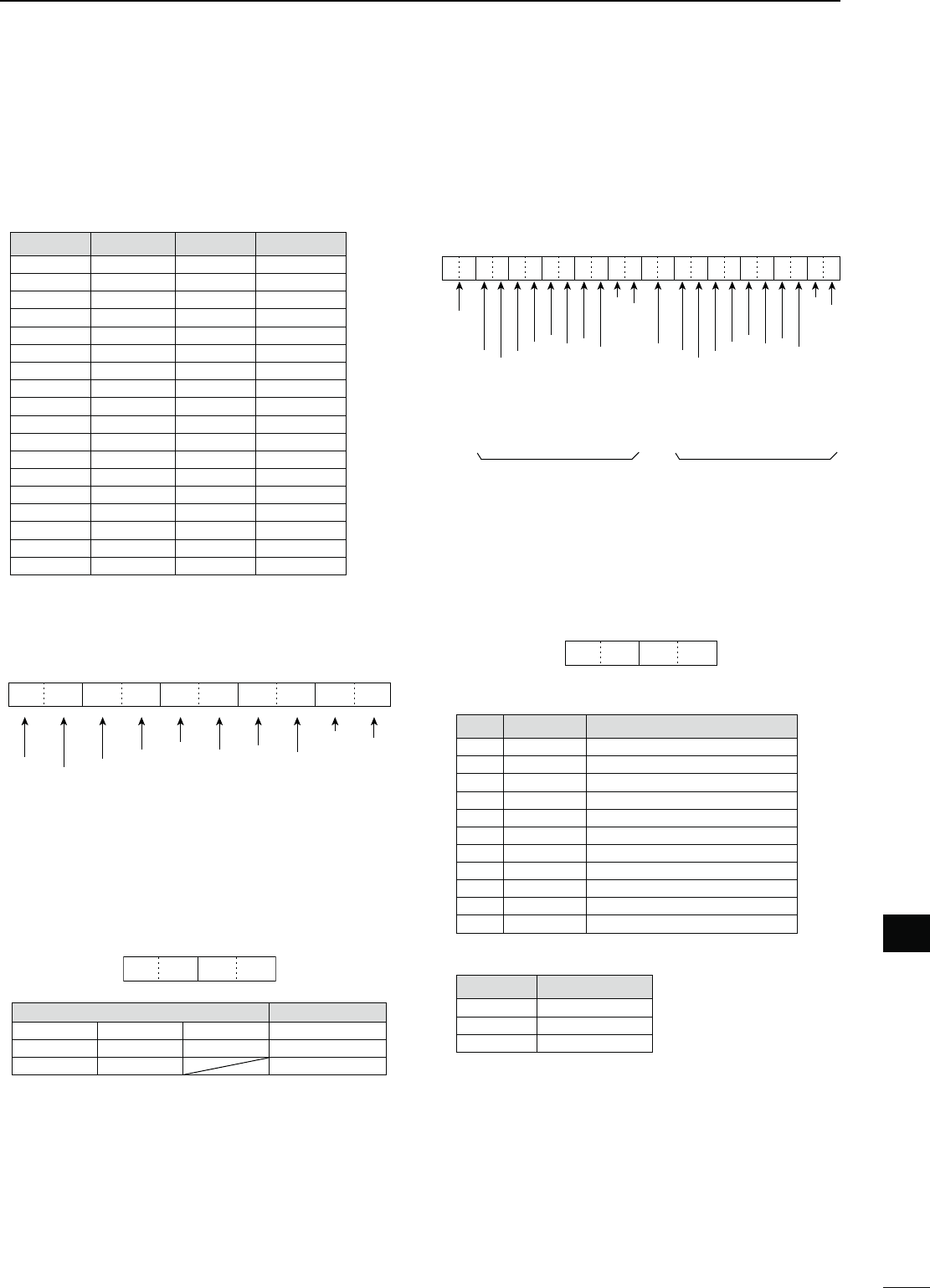
106
CONTROL COMMAND
1
2
3
4
5
6
7
8
9
10
11
12
13
15
16
17
19
20
21
14
18
14
s#HARACTERCODESETTING
Command : 1A 00
#HARACTER !3#))CODE #HARACTER !3#))CODE
A–Z 41–5A a–z 61–7A
0–9 30–39 Space 20
!21#23
$2425
26 <5C
?3F " 22
’27` 60
^5E+2B
–2D12A
⁄2F.2E
,2C: 3A
;3B=3D
<3C> 3E
(28) 29
[5B] 5D
{7B} 7D
¦7C_5F
–7E@40
s/PERATINGFREQUENCY
Command : 00, 03, 05
q
XXXXX
we
X
rt
XX XX
10 Hz digit: 0–9
1 Hz digit: 0–9
1 kHz digit: 0–9
100 Hz digit: 0–9
100 kHz digit: 0–9
10 kHz digit: 0–9
10 MHz digit: 0–9
1 MHz digit: 0–9
1000 MHz digit: 0–1
100 MHz digit: 0–4
s/PERATINGMODE
Command : 01, 04, 06
q
XXXX
w
q /PERATINGMODE w &ILTERSETTING
00: LSB 03: CW 07: CW-R 01: FIL1
01: USB 04: RTTY 08: RTTY-R 02: FIL2
02: AM 05: FM 03: FIL3
Filter setting (w) can be skipped with command 01
and 06. In that case, “FIL1” is automatically selected
with command 01 and the default filter setting of the
operating mode is selected with command 06.
s"ANDEDGEFREQUENCYSETTING
Command 02*, 1E 01, 1E 03
q
XXX
wertyuio!0 !1 !2
XXXXXXXXX2DXXXXXXXXXX
10 Hz digit: 0–9
1 Hz digit: 0–9
1 kHz digit: 0–9
100 Hz digit: 0–9
100 kHz digit: 0–9
10 kHz digit: 0–9
10 MHz digit: 0–9
1 MHz digit: 0–9
1000 MHz digit: 0 (fixed)
100 MHz digit: 0 (fixed)
10 Hz digit: 0–9
1 Hz digit: 0–9
1 kHz digit: 0–9
100 Hz digit: 0–9
100 kHz digit: 0–9
10 kHz digit: 0–9
10 MHz digit: 0–9
1 MHz digit: 0–9
1000 MHz digit: 0 (fixed)
100 MHz digit: 0 (fixed)
Separator (fixed)
Lower edge Higher edge
Edge number*: 01–30
* Edge number setting is not necessary with com-
mand 02.
s"ANDSTACKINGREGISTER
Command : 1A 01
q
XXXX
w
q Frequency band code
#ODE &REQBAND &REQUENCYRANGEUNIT-(Z
01 1.8 1.800000– 1.999999
02 3.5 3.400000– 4.099999
03 7 6.900000– 7.499999
04 10 9.900000–10.499999
05 14 13.900000–14.499999
06 18 17.900000–18.499999
07 21 20.900000–21.499999
08 24 24.400000–25.099999
09 28 28.000000–29.999999
10 50 50.000000–54.000000
14 GENE Other than above
w Register code
#ODE 2EGISTERED.O
01 1 (latest)
02 2
03 3 (oldest)
For example, when reading the oldest contents in the
21 MHz band, the code “0703” is used.
When sending the contents, the codes, such as op-
erating frequency and operating mode*, should be
added after the register code, as shown above.
* See “Memory content setting (r to !7)” for details.
(p. 108)
D$ATACONTENTDESCRIPTION
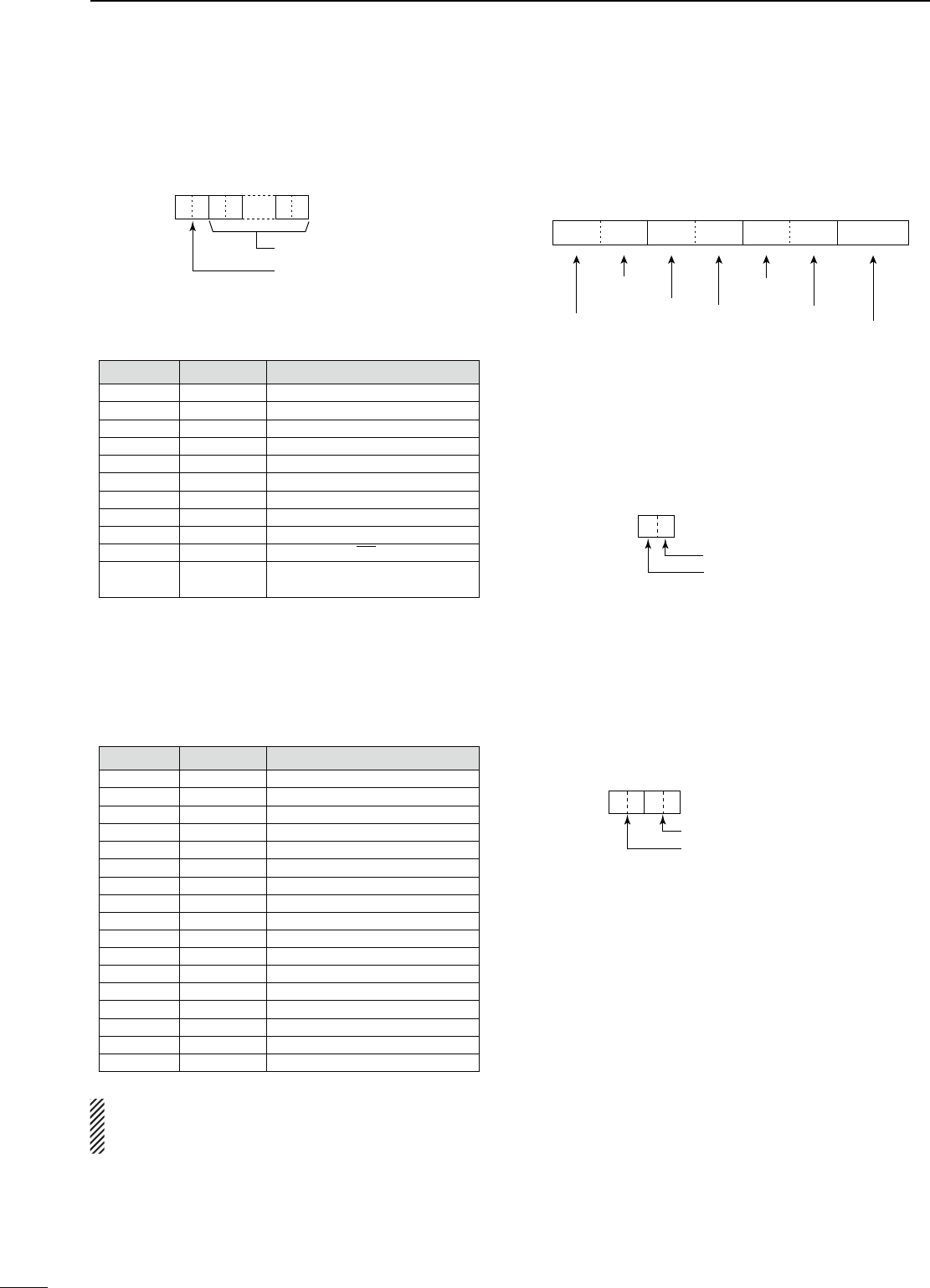
107
CONTROL COMMAND
14
s-EMORYKEYERCONTENTS
Command : 1A 02
X
q: Channel data
w–&1: Text data
XXX…… XX
01: M1
02: M2
03: M3
04: M4
s#HARACTERSCODE
#HARACTER !3#))CODE $ESCRIPTION
0–9 30–39 Number
A–Z 41–5A Alphabetical characters
a–z 61–7A Alphabetical characters
space 20 Word space
/ 2F Symbol
? 3F Symbol
, 2C Symbol
. 2E Symbol
@ 40 Symbol
^5E
e.g., to send BT, enter ^BT
12A Inserts contest number (can be
used for 1 channel only)
s#7MESSAGECONTENTS
Command : 17 Up to 30 characters
To send CW messages, the following character codes
are used.
s#HARACTERSCODE
#HARACTER !3#))CODE $ESCRIPTION
0–9 30–39 Number
A–Z 41–5A Alphabetical characters
a–z 61–7A Alphabetical characters
space 20 Word space
/ 2F Symbol
? 3F Symbol
. 2E Symbol
– 2D Symbol
, 2C Symbol
: 3A Symbol
’ 27 Symbol
( 28 Symbol
) 29 Symbol
= 3D Symbol
+ 2B Symbol
” 22 Symbol
@ 40 Symbol
sh&&vSTOPSSENDING#7MESSAGES
sh>vISUSEDTOTRANSMITASTRINGOFCHARACTERSWITH
no inter-character space.
s3PLITOFFSETFREQUENCYSETTING
Command : 1A 05 0012, 0013
1 kHz digit: 0–9
100 Hz digit: 0 (fixed)
100 kHz digit: 0–9
10 kHz digit: 0–9
10 MHz digit: 0 (fixed)
1 MHz digit: 0–9
Direction:
00: + direction
01: – direction
q
0XXXXXX
we
0
r
s33"TRANSMISSIONBANDWIDTHSETTING
Command : 1A 05 0050, 0051, 0052
XX
Lower edge
Higher edge
Lower edge
0: 100Hz
1: 200Hz
2: 300Hz
3: 500Hz
Higher edge
0: 2500Hz
1: 2700Hz
2: 2800Hz
3: 2900Hz
s28(0&AND,0&SETTINGSINEACH
OPERATINGMODE
Command : 1A 05 0045, 0053, 0058, 0063, 0064
XXXX
LPF (upper side)
HPF (lower side)
HPF
0: through
1 to 20: 100 to 2000 Hz
LPF
5 to 24: 500 to 2400 Hz
25: through
Set the LPF value larger than HPF one.
D Data content description (continued)
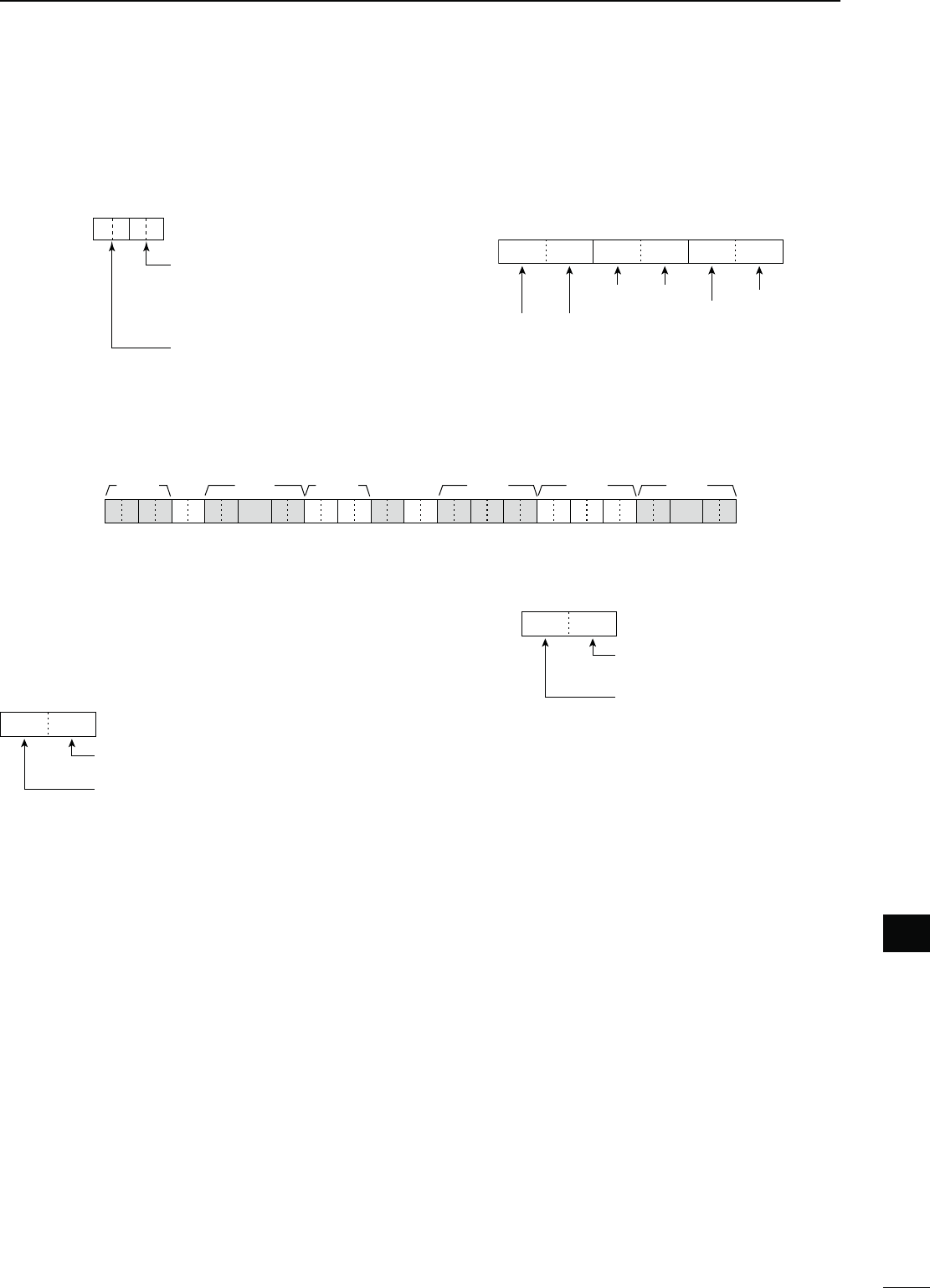
108
CONTROL COMMAND
1
2
3
4
5
6
7
8
9
10
11
12
15
16
17
19
20
21
14
18
14
13
s$ATAMODEWITHlLTERWIDTHSETTING
Command : 1A 06
XXXX
qw
00: Data mode OFF
01: FIL1
02: FIL2
03: FIL3
00: Data mode OFF
01: Data mode ON
s2EPEATERTONETONESQUELCHFREQUENCY
SETTING
Command : 1B 00, 1B 01
q*ew
00XXXX
0 (fixed)
0 (fixed)
100 Hz digit
10 kHz digit
1 Hz digit
0.1 Hz digit
*Not necessary when setting a frequency.
q, w Memory channel number
0000–0099 : Memory channel 0 to 99
0100 : Programmed scan edge P1
0101 : Programmed scan edge P2
e Split and Select memory settings
XX
e
0: Select memory OFF
1: Select memory ON
0: Split OFF
1: Split ON
When the program channel is selected, both settings
should be “0.”
r–i Operating frequency setting
3EEhs/PERATINGFREQUENCYv
o, !0 Operating mode setting
3EEhs/PERATINGMODEv
!1 $ATAMODESETTING
1 byte data (XX)
00: Data mode OFF
01: Data mode ON
!2 Tone setting
XX
!2
0: OFF, 1: Tone
2: TSQL
0 (fixed)
!3–!5 Repeater tone frequency setting
!6–!8 Tone squelch frequency setting
3EEhs2EPEATERTONETONESQUELCHSETTINGv
!9–@7 Memory name setting
Up to 9 characters.
3EEhs#HARACTERCODESETTINGv
‘1A 00’ command with the format as below clears the
data of the selected memory channel.
q, w : Memory channel 0 to 99
e : FF
r or later : None
s-EMORYCONTENTSETTING
Command : 1A 00
X
er–io, !0 !1 !2 !3–!5 !9–@7!6–!8
XXX……XXXXXXXXXXXXXXXXXX XXXX XXXX ……XX XX
q, w

109
SPECIFICATIONS
15
N General
s&REQUENCYCOVERAGE UNIT-(Z
Receive
0.030–60.000*1*2
Transmit
1.800–1.999*2, 3.500–3.999*2,
5.33200*3, 5.34800*3, 5.35850*3,
5.37300*3, 5.40500*3,
7.000–7.300*2, 10.100–10.150*2,
14.000–14.350*2, 18.068–18.168*2,
21.000–21.450*2, 24.890–24.990*2,
28.000–29.700*2, 50.000–54.000*2
*1Some frequency bands are not guaranteed.
*2Depending on version. *3
Only USA version.
s-ODE 53",3"#72449!-&-
s.OOFMEMORYCHANNELS#( ( 99 regular, 2 scan edges)
s!NTENNAIMPEDANCE ø ( at Antenna Tuner OFF)
s!NTENNACONNECTORTYPE 3/× 2
s4EMPERATURERANGE #TO#&TO&
s&REQUENCYSTABILITY ,ESSTHANÒPPMMINAFTER
power ON. #TO#&
TO&
s&REQUENCYRESOLUTION (Z
s0OWERSUPPLY
6$#Ò(negative ground)
s0OWERCONSUMPTION
Transmit
Max. power : 23.0 A
Receive
Standby : 2.2 A
Max. audio : 3.0 A
s$IMENSIONS 7× 116(H) × 343(D) mm
(projections not included) 125⁄16(W) × 49⁄16(H) × 131⁄2(D) in
s7EIGHTAPPROX KGLB
s!##CONNECTOR PIN
s#)6CONNECTOR CONDUCTORDMM1⁄8″)
N4RANSMITTER
s/UTPUTPOWER(continuously adjustable)
SSB/CW/RTTY/FM : 2 to 100 W
AM : 2 to 27 W* (*Carrier power)
AT6$##
s-ODULATIONSYSTEM
SSB : Digital PSN modulation
AM : Digital Low power modulation
FM : Digital Phase modulation
s3PURIOUSEMISSION
HF bands : Less than –50 dB
50 MHz band : Less than –63 dB
s#ARRIERSUPPRESSION -ORETHAND"
s5NWANTEDSIDEBAND
suppression : More than 55 dB
s∂TX variable range : ±9.999 kHz
s-ICROPHONECONNECTOR PINCONNECTOR(600 ø)
s%,%#+%9CONNECTOR CONDUCTORDMM1⁄4″)
s+%9CONNECTOR CONDUCTORDMM1⁄4″)
s3%.$CONNECTOR 0HONOJACK(RCA)
s!,#CONNECTOR 0HONOJACK(RCA)

110
SPECIFICATIONS
1
2
3
4
5
6
7
8
9
10
11
12
13
16
17
18
20
21
19
15
14
15
N2ECEIVER
s2ECEIVESYSTEM
Double superheterodyne system
s)NTERMEDIATEFREQUENCIES
1st : 64.455 MHz
2nd : 36 kHz
s3ENSITIVITY
SSB, CW : 0.16 μV (1.80–29.99 MHz)*4
(10 dB S/N) BW=2.4 kHz 0.13 μV (50.0–54.0 MHz)*5
AM (10 dB S/N) : 12.6 μV (0.5–1.799 MHz)*4
BW=6 kHz 2.0 μV (1.80–29.99 MHz)*4
1.6 μV (50.0–54.0 MHz)*5
FM (12 dB SINAD) : 0.5 μV (28.0–29.7 MHz)*4
BW=15 kHz 0.32 μV (50.0–54.0 MHz)*5
s3QUELCHSENSITIVITY
&REQUENCYBAND 3QUELCHSENSITIVITY
HF SSB : Less than 5.6 μV*4
FM : Less than 0.32 μV*4
50 MHz SSB : Less than 5.6 μV*5
FM : Less than 0.32 μV*5
*4 Pre-amp 1 is ON. *5 Pre-amp 2 is ON.
s3ELECTIVITY)&lLTERSHAPEISSETTO3(!20
SSB (BW: 2.4 kHz) : More than 2.4 kHz/–6 dB
Less than 3.4 kHz/–40 dB
CW (BW: 500 Hz) : More than 500 Hz/–6 dB
Less than 700 Hz/–40 dB
RTTY (BW: 350 Hz) : More than 500 Hz/–6 dB
Less than 800 Hz/–40 dB
AM (BW: 6 kHz) : More than 6.0 kHz/–6 dB
Less than 10.0 kHz/–40 dB
FM (BW: 15 kHz) : More than 12.0 kHz/–6 dB
Less than 22.0 kHz/–40 dB
s3PURIOUSANDIMAGEREJECTIONRATIO
: More than 70 dB
s!&OUTPUTPOWER -ORETHAN7AT
(at 13.8 V DC) distortion with an 8 ø load
s2)4VARIABLERANGE ÒK(Z
s0(/.%3CONNECTOR
3-conductor 6.35 (d) mm (1⁄4″)
s%XTERNAL30CONNECTOR CONDUCTORDMM
(1⁄8″)/8 ø
s$30!.&ATTENUATION -ORETHAND"
(with 1 kHz single tone)
s$30-.&ATTENUATION -ORETHAND"
s$30.2ATTENUATION -ORETHAND"
(noise rejection in SSB)
N!NTENNATUNER
s-ATCHINGIMPEDANCERANGE
HF bands : 16.7 to 150 ø unbalanced
(Less than VSWR 1:3)
50 MHz band : 20 to 125 ø unbalanced
(Less than VSWR 1:2.5)
s-INIMUMOPERATINGINPUT 7 (HF bands)
power 15 W (50MHz band )
s4UNINGACCURACY 6372ORLESS
s)NSERTIONLOSS(after tuning at RF power 100W)
1.8 MHz band : 1.2 dB or less
Bands other than 1.8 MHz : 1.0 dB or less
Spurious signals may be displayed on the spectrum scope screen
regardless of the transceiver’s state (Tx or Rx). They are gener-
ated in the scope circuit. This does not indicate a transceiver mal-
function.
All stated specifications are typical and subject to change without
notice or obligation.
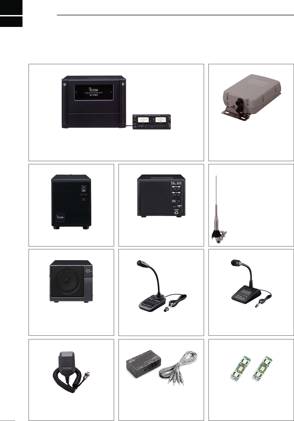
111
OPTIONS
16
AH-4 HF AUTOMATIC ANTENNA TUNER
Specially designed to tune a long wire
antenna for HF/50 MHz bands partic-
ularly in portable or mobile operation.
The “PTT tune” function provides sim-
ple operation.
s)NPUTPOWERRATING7
AH-2b ANTENNA ELEMENT
A 2.5 m long antenna ele-
ment for mobile operation
with the AH-4.
s&REQUENCY COVERAGE
7–54 MHz band with the
AH-4
SM-30 DESKTOP MICROPHONE
Unidirectional, electret microphone for
base station operation. Includes low
cut switch and mic gain control.
SM-50 DESKTOP MICROPHONE
Unidirectional, dynamic microphone for
base station operation. Includes [UP]/
[DOWN] switches, a low cut switch and
mic gain control.
SP-23 EXTERNAL SPEAKER
4 audio filters; headphone jack; can
connect to 2 transceivers.
s)NPUTIMPEDANCEø
s-AXINPUTPOWER7
HM-36 HAND MICROPHONE
Hand microphone equipped with [UP]/
[DOWN] switches.
The same as that attached with the
transceiver.
IC-PW1/EURO HF/50 MHz ALL BAND 1 kW LINEAR AMPLIFIER
Full-duty 1 kW linear amplifier including an automatic antenna tuner. Has auto-
matic tuning and band selection capability. Full break-in (QSK) operation is pos-
sible. The amplifier/power supply unit and the remote control unit are separated.
The optional OPC-599 ADAPTER CABLE is required for connection.
PS-126 DC POWER SUPPLY
s/UTPUTVOLTAGE6$#
s-AXOUTPUTCURRENT!
N/PTIONS
FL-430 1ST IF FILTER (6 kHz)
FL-431 1ST IF FILTER (3 kHz)
6 kHz or 3 kHz roofing filter can be
used.
The roofing filters reduce interfer-
ence from strong nearby signals.
SP-21 EXTERNAL SPEAKER
Designed for base station operation.
s)NPUTIMPEDANCEø
s-AXINPUTPOWER7
CT-17 CI-V LEVEL CONVERTER UNIT
For remote transceiver control using a
personal computer equipped with an
RS-232C port. You can change fre-
quencies, operating mode, memory
channels, etc., via your computer.

112
OPTIONS
1
2
3
4
5
6
7
8
9
10
11
12
13
14
17
18
19
21
20
16
15
16
s OPC-599 ADAPTER CABLE
13-pin, ACC connector to 7-pin + 8-pin ACC connector.
s-" CARRYING HANDLE
Convenient when carrying the transceiver.
The same as that supplied with the transceiver.
s OPC-420 SHIELD CONTROL CABLE
For the connection between transceiver and the AH-4.
s23"! IP REMOTE CONTROL SOFTWARE
To remotely control radios using the RS-BA1, "%352%
that you comply with your local regulations.
Approved Icom optional equipment is designed for
optimal performance when used with an Icom trans-
ceiver.
Icom is not responsible for the destruction or damage
to an Icom transceiver in the event the Icom trans-
ceiver is used with equipment that is not manufac-
tured or approved by Icom.
113
CE
17
INSTALLATION NOTES
For amateur base station installations it is recom-
mended that the forward clearance in front of the an-
tenna array is calculated relative to the EIRP (Effective
Isotropic Radiated Power). The clearance height below
the antenna array can be determined in most cases
from the RF power at the antenna input terminals.
As different exposure limits have been recommended
for different frequencies, a relative table shows a
guideline for installation considerations.
Below 30 MHz, the recommended limits are specified
in terms of V/m or A/m fields as they are likely to fall
within the near-field region. Similarly, the antennas
may be physically short in terms of electrical length
and that the installation will require some antenna
matching device which can create local, high inten-
sity magnetic fields. Analysis of such MF installations
is best considered in association with published guid-
ance notes such as the FCC OET Bulletin 65 Edition
97-01 and its annexes relative to amateur transmitter
installations.
The EC recommended limits are almost identical to
the FCC specified ‘uncontrolled’ limits and tables exist
that show pre-calculated safe distances for different
antenna types for different frequency bands. Further
information can be found at http://www.arrl.org/.
s4YPICALAMATEURRADIOINSTALLATION
Exposure distance assumes that the predominant ra-
diation pattern is forward and that radiation vertically
downwards is at unity gain (sidelobe suppression is
equal to main lobe gain). This is true of almost every
gain antenna today. Exposed persons are assumed
to be beneath the antenna array and have a typical
height of 1.8 m.
The figures assume the worst case emission of a con-
stant carrier.
For the bands 10 MHz and higher the following power
density limits have been recommended:
10–50 MHz 2 W/sq m
6ERTICALCLEARANCEBY%)20OUTPUT
1 Watts 2.1 m
10 Watts 2.8 m
25 Watts 3.4 m
100 Watts 5 m
1000 Watts 12 m
&ORWARDCLEARANCEBY%)20OUTPUT
100 Watts 2 m
1000 Watts 6.5 m
10,000 Watts 20 m
100,000 Watts 65 m
In all cases any possible risk depends on the trans-
mitter being activated for long periods. (actual recom-
mendation limits are specified as an average during 6
minutes) Normally the transmitter is not active for long
periods of time. Some radio licenses will require that a
timer circuit automatically cuts off the transmitter after
1–2 minutes etc.
Similarly some modes of transmission, SSB, CW, AM
etc. have a lower ‘average’ output power and the as-
sessed risk is even lower.
Versions of the IC-7410 which display the
“CE” symbol on the serial number label,
comply with the essential requirements of
the European Radio and Telecommunica-
tion Terminal Directive 1999/5/EC.
This warning symbol indicates that this
equipment operates in non-harmonised
frequency bands and/or may be subject to
licensing conditions in the country of use.
Be sure to check that you have the correct
version of this radio or the correct program-
ming of this radio, to comply with national
licensing requirement.
s,ISTOF#OUNTRYCODES)3/
#OUNTRY #ODES #OUNTRY #ODES
1
2
3
4
5
6
7
8
9
10
11
12
13
14
15
16
17
Austria
Belgium
Bulgaria
Croatia
Czech Republic
Cyprus
Denmark
Estonia
Finland
France
Germany
Greece
Hungary
Iceland
Ireland
Italy
Latvia
AT
BE
BG
HR
CZ
CY
DK
EE
FI
FR
DE
GR
HU
IS
IE
IT
LV
18
19
20
21
22
23
24
25
26
27
28
29
30
31
32
33
Liechtenstein
Lithuania
Luxembourg
Malta
Netherlands
Norway
Poland
Portugal
Romania
Slovakia
Slovenia
Spain
Sweden
Switzerland
Turkey
United Kingdom
LI
LT
LU
MT
NL
NO
PL
PT
RO
SK
SI
ES
SE
CH
TR
GB

114
CE
1
2
3
4
5
6
7
8
9
10
11
12
13
14
15
16
18
19
20
21
17
17
DECLARATION
OF CONFORMITY
We Icom Inc. Japan
1-1-32, Kamiminami, Hirano-ku
Osaka 547-0003, Japan
Kind of equipment:
Type-designation:
Signature
Authorized representative name
Place and date of issue
Version (where applicable): Y. Furukawa
General Manager
Icom (Europe) GmbH
Communication Equipment
Auf der Krautweide 24,
65812 Bad Soden am Taunus,
Germany
HF/50 MHz TRANSCEIVER
iC-
7410
14th Jan.
2011Bad Soden
Declare on our sole responsibility that this equipment complies with the
essential requirements of the Radio and Telecommunications Terminal
Equipment Directive, 1999/5/EC, and that any applicable Essential Test
Suite measurements have been performed.
This compliance is based on conformity with the following harmonised
standards, specifications or documents:
EN 301 489-1 v1.6.1 (September 2005)
EN 301 489-15 v1.2.1 (August 2002)
EN 301 783-2 v1.1.1 (September 2000)
EN 60950-1 2006 A11:2009
i)
ii)
iii)
iv)
v)
vi)

MEMO

MEMO
1
2
3
4
5
6
7
8
9
10
11
12
13
14
15
16
17
18
19
20
21
1-1-32 Kamiminami, Hirano-ku, Osaka 547-0003, Japan
A-6904H-1EX
Printed in Japan
© 2011 Icom Inc.
< Intended Country of Use >
AT
FI
IT
PL
GB
RO
BE
FR
LV
PT
IS
TR
CY
DE
LT
SK
LI
HR
CZ
GR
LU
SI
NO
DK
HU
MT
ES
CH
EE
IE
NL
SE
BG
< Intended Country of Use >
AT
FI
IT
PL
GB
RO
BE
FR
LV
PT
IS
TR
CY
DE
LT
SK
LI
HR
CZ
GR
LU
SI
NO
DK
HU
MT
ES
CH
EE
IE
NL
SE
BG
< Intended Country of Use >
AT
FI
IT
PL
GB
RO
BE
FR
LV
PT
IS
TR
CY
DE
LT
SK
LI
HR
CZ
GR
LU
SI
NO
DK
HU
MT
ES
CH
EE
IE
NL
SE
BG
< Intended Country of Use >
AT
FI
IT
PL
GB
RO
BE
FR
LV
PT
IS
TR
CY
DE
LT
SK
LI
HR
CZ
GR
LU
SI
NO
DK
HU
MT
ES
CH
EE
IE
NL
SE
BG
IC-7410 #11
(France)
< Intended Country of Use >
AT
FI
IT
PL
GB
RO
BE
FR
LV
PT
IS
TR
CY
DE
LT
SK
LI
HR
CZ
GR
LU
SI
NO
DK
HU
MT
ES
CH
EE
IE
NL
SE
BG
IC-7410 #03
(Europe)
IC-7410 #04
(Europe-1)
IC-7410 #05
(Italy)
IC-7410 #06
(Spain)