ICOM orporated 322800 Class B AIS Transponder User Manual MA 500TR Instruction Manual
ICOM Incorporated Class B AIS Transponder MA 500TR Instruction Manual
UserManual.wiki
>
ICOM orporated
>
322800 User Manual
User Manual
Navigation menu
Upload a User Manual
Namespaces
Wiki Guide
HTML
PDF
Info
Views
User Manual
Discussion / Help
Navigation
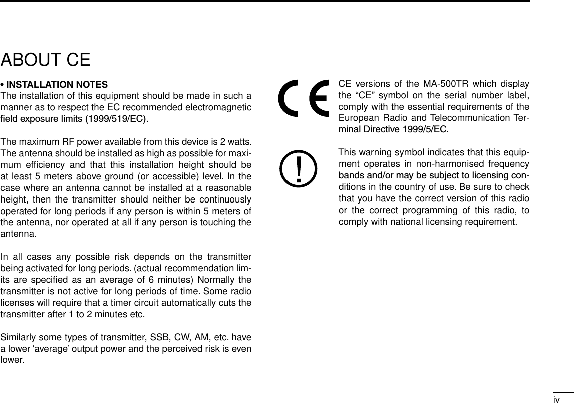
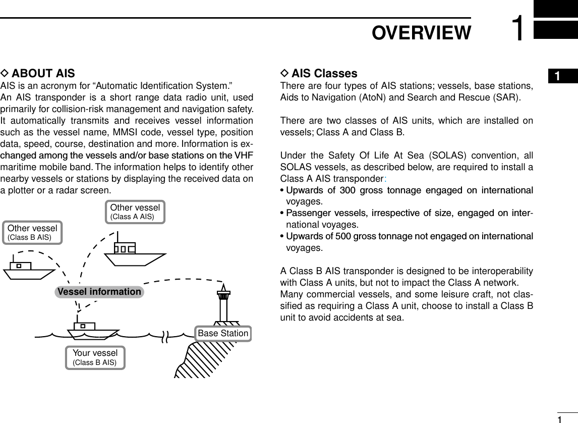
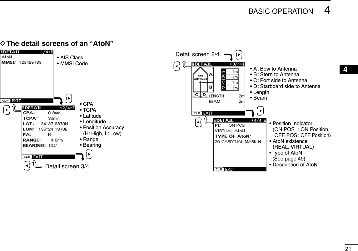
![2New2001PANEL DESCRIPTION2■ Front panelFunction display (p. 4)Speakerqw erwetyiouThe angle brackets show common or special display op-erations, as described below:•<Common> shows the common operation.•<In the plotter display> shows the plotter display opera-tion.•<In the target list display> shows the target list display operation.•<In the danger list display> shows the danger list dis-play operation.q DISPLAY MODE KEY [DISP MODE] <Common> ➥ Push to switch the display mode between the plotter, targetlistanddangerlist.(pp.4−6) ➥ While in the Menu mode, push to exit it, and return to the plotter, target list or danger list display which was selected before you entered the Menu mode.w LEFT AND RIGHT KEYS [Ω]/[≈] <Common> While in the Menu item setting mode, push to select a menu option. (pp. 29, 33) <In the plotter display> ➥ Push [Ω] to sequentially select each AIS target icon far-thest from your vessel (or waypoint, if it is set; see page 24forsettingdetail). (p. 15) ➥ Push [≈] to sequentially select each AIS target icon closest to your vessel (or waypoint, if it is set; see page 24forsettingdetail). (p. 15) •A target box will appear around the selected target or waypoint icon. <In the danger list display> ➥ Push [Ω] to sort the AIS target data by CPA (Closest Point of Approach). (p. 17) ➥ Push [≈] to sort the AIS target data by TCPA (Time to CPA). (p. 17)](https://usermanual.wiki/ICOM-orporated/322800/User-Guide-1517361-Page-10.png)
![32PANEL DESCRIPTIONNew2001e UP AND DOWN KEYS [∫]/[√] <Common> ➥ While in the Menu mode, push to select a menu item. (pp. 9, 28) ➥ Push to select a voice channel in the voice channel se-lection screen. (p. 21) <In the plotter display> Push to select the display range. (p. 15) <In the target or danger list display> Push to select an AIS target in the target or danger list display. (pp. 16, 17)r ENTER KEY [ENT] <Common> ➥ Push to display the detail screen of the selected AIS target.(pp.15−17) ➥ Push to save the input data. (pp. 8, 10, 15) ➥ Push to enter the Menu item setting mode. (pp. 9, 28) ➥ While in the Menu item setting mode, push to select a menu option. (pp. 11, 12, 16, 29, 32−34) ➥ While searching for a GPS satellite, push [ENT] to dis-playtheGPSinformationscreen.(p.14,31)t MENU KEY [MENU] <Common> ➥ Push to enter the Menu mode. (pp. 9, 28) ➥ While in the Menu mode, push to exit it, and return to the plotter, target list or danger list display which was selected before you entered the Menu mode.y CLEAR KEY [CLEAR] <Common> ➥ Push to cancel the entered function, or return to the pre-vious screen. (pp. 10, 13, 23) ➥ While in the Menu mode, push to exit it, and return to the previous screen. (pp. 9, 28) ➥Pushtostopanalarm.(pp.15−17)u DSC KEY [DSC] <Common> ➥ When the AIS target is selected, or the detail screen is displayed, push to display the voice channel selection screen. (p. 22) ➥ After selecting the voice channel, push to transmit an Individual DSC call to the selected AIS target. (p. 22) This function is available only when a transceiver is con-nected to the transponder. (p. 39)i POWER/BRILL KEY [POWER•BRILL] <Common> ➥ Hold down for 1 second to turn the power ON or OFF. (p.14) •After turning ON the power, the opening screen will appear. ➥ Push to show the display backlight and contrast adjust-ing screen. (p. 15)o MAN OVERBOAT KEY [MOB] <Common> Hold down for 1 second to set the waypoint. (p. 25) •TheMOBalarmsounds,andaagiconappearsonyourcurrentposition.2](https://usermanual.wiki/ICOM-orporated/322800/User-Guide-1517361-Page-11.png)
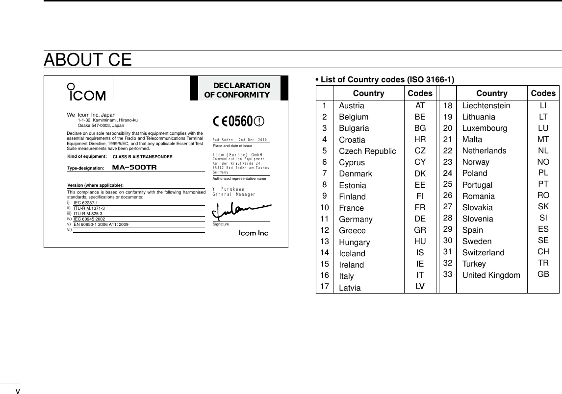
![42PANEL DESCRIPTIONNew2001■ Function displayThere are three display types; plotter, target list and danger list, and you can select your desired type using the [DISP MODE] key.NOTE: When one of the following messages is displayed on the function display, push [CLEAR] to clear it.•“PRIORITYINTERRUPTEDLASTATTEMPTS”isdisplayedwhen the transponder cannot make a periodic transmission because the transponder detects a transmit signal.•“BASESTATIONINHIBITINGAISTXFORMM MIN”* is dis-played when the transmission is inhibited by a base station for the displayed time period. *The transmission inhibit period is displayed instead of “MM.” - “ ” is also displayed while transmission is inhibited.D Plotter displayAfter the transponder is turned ON, the plotter display automati-cally appears, if the GPS receiver is connected and it receives signals from a satellite. It shows the display range and the icons of the AIS targets.rytqewuiq DISPLAY TYPE Shows the selected display type. •When“N-UP” is displayed,thetop oftheplotterdisplayrepre-sents North. •When“AC-UP”isdisplayed,thetopoftheplotterdisplayrepre-sents the direction your course is heading.w RANGE/CPA INFORMATION ➥ Shows the range information from your vessel to the se-lected AIS target. ➥ Shows the CPA (Closest Point of Approach) information of the selected AIS target whose CPA is within 6 nm (nautical miles) and TCPA (Time to CPA) is within 60 minutes of your vessel.e BEARING/TCPA INFORMATION ➥ Shows the bearing information from your vessel to the selected AIS target. ➥ Shows TCPA information of the selected AIS target whose CPA is within 6 nm (nautical miles) and TCPA is within 60 minutes of your vessel.r MESSAGE ICON Appears when a message is received. •The message icon stays on the plotter display as long as the unread message is stored in the RX log memory.](https://usermanual.wiki/ICOM-orporated/322800/User-Guide-1517361-Page-12.png)
![52PANEL DESCRIPTIONNew200112345678910111213141516t TARGET BOX Shows the selected AIS target (or waypoint, if it is set; see pages24–26forsettingdetail). •When a target box appears, push [ENT] to display the detail screen of the selected AIS target or waypoint.y YOUR VESSEL ICON Your vessel icon is displayed in the center of the display. •When“N-UP”isdisplayed,thevesseliconautomaticallypointsinthedirectionyouareheading,in45degreessteps. •When“AC-UP”isdisplayed,thevesseliconconstantlypointstothe top of the plotter display. •Whenyourvessel moves less than 2 knots, the icon is displayed as “ .”u KEY ENTRY GUIDE Shows the key entry guide. ➥ Push [Ω] or [≈] to select each AIS target icon (or way-point), in sequence. (p. 15) •A target box will appear around the selected target icon. ➥ Push [ENT] to display the detail screen of the selected AIS target or waypoint. (pp. 15–17)i DISPLAY RANGE Shows the selected display range. •0.125,0.25,0.5,0.75,1.5,3,6,12,24nm(nauticalmiles)areselectable.• Description of the iconsIcon DescriptionAIStarget:VesselThe tip of the target triangle automatically points in the direction it’s heading.The icon blinks when the AIS target is closer than your CPA and TCPA settings. (Dangerous target)AIS target: Lost target*The target triangle is marked with a diagonal line.AIS target: Base StationAIS target: Search and Rescue (SAR)AIS target: Aids to Navigation (AtoN)Waypoint* A vessel is regarded as a “Lost target” after a specified pe-riod of time has passed since the vessel last transmitted data. (p. 27) The “Lost target” icon disappears from the plotter display 6 minutesand 40seconds(default)after the vesselwas re-garded as a “Lost target.” Ask your dealer for details.](https://usermanual.wiki/ICOM-orporated/322800/User-Guide-1517361-Page-13.png)
![62PANEL DESCRIPTIONNew2001■ Function display (Continued)D Target list displayIn the plotter display, push [DISP MODE] to switch to the tar-get list display, which shows all AIS targets being detected by the transponder.The AIS target data is sorted by the distance from your ves-sel, and the closest target is located on the top of the list.eqwq THE NUMBER OF TARGETS Shows the number of AIS targets which are being detected by the transponder.w KEY ENTRY GUIDE Shows the key entry guide. ➥ Push [∫] or [√] to select an AIS target. (p. 16) ➥ Push [ENT] to display the detail screen of the selected AIS target. (pp. 16, 17)e TARGET INFORMATION Shows the following AIS target information: •MMSIcodeorname, if the name is programmed. •Range(RNG)fromyourvesseltothetarget(unit:nauticalmile) •Bearing(BRG)fromyourvesseltothetarget(unit:degree)D Danger list displayIn the target list display, push [DISP MODE] to switch to the danger list display, which helps you to find any dangerous target whose CPA is within 6 nm (nautical miles) and TCPA is within 60 minutes of your vessel.eqwq THE NUMBER OF DANGEROUS TARGETS Shows the number of AIS targets which are being detected by the transponder.w KEY ENTRY GUIDE Shows the key entry guide. ➥ Push [Ω] or [≈] to sort the danger target data. (p. 17) ➥ Push [ENT] to display the detail screen of the selected AIS target. (p. 17)e DANGER TARGET INFORMATION Shows the following dangerous target information: •MMSIcodeorname, if the name is programmed. •CPA :ClosestPointofApproach(unit:nauticalmile) •TCPA:TimetoCPA(unit:minute)New2001](https://usermanual.wiki/ICOM-orporated/322800/User-Guide-1517361-Page-14.png)
![73PREPARATIONNew200112345678910111213141516■ MMSI code settingThe 9-digit MMSI (Maritime Mobile Service Identity: DSC self ID) code can be set at power ON. If the MMSI code has al-ready been set, the following steps are not needed. Go to page 9.This initial code setting can be performed only once.After being set, it can be changed by only your dealer or distributor.q Hold down [POWER•BRILL] for 1 second to turn ON the power. •A long beep sounds, and the opening screen appears.[POWER•BRILL]w The opening screen displays the results of the opening test (ROM, RAM and backup data test); “OK” or “NG” (No Good). •If “NG” is displayed, hold down [POWER•BRILL] for 1 second to turn OFF the power, then ON again to reset the transponder. If there is no change, contact your dealer or service center.e After the opening test is completed, “No MMSI” appears when no MMSI code is set. •If the MMSI code has already been set, the MMSI code appears. Go to page 9. •Push[CLEAR] to skip the setting, and go to the plotter display. In this case, the transponder operates as just an AIS receiver.☞ Continued on the next page.](https://usermanual.wiki/ICOM-orporated/322800/User-Guide-1517361-Page-15.png)
![83PREPARATIONNew2001■ MMSI code setting (Continued)r Push [ENT] to enter the MMSI code setting mode.t Push [∫] or [√] to input the specific 9-digit MMSI code. •Push[≈] to move the cursor forward. •Push[Ω] to move the cursor backward. •Push[CLEAR] to cancel, and go to the plotter display. In this case, the transponder operates as just an AIS receiver.[CLEAR][ENT][∫], [√],[Ω], [≈]NOTE: The coast station ID or the group ID cannot be en-tered as your MMSI code.•GroupID :Therstonedigitis“0.”•CoaststationID:Thersttwodigitsare“0.”If you enter a code that starts with “0” or “00,” an error beep sounds after pushing [ENT] in step y.y After inputting the 9-digit code, push [ENT]. •TheMMSIconfirmationscreenappears.u Input the same MMSI code which was entered in steps t and y for the confirmation. Then, push [ENT] to save.i After the MMSI code has been saved, the transponder au-tomatically enters the Initial setting mode. See pages 9 to 13 for setting details. The Initial setting mode can also be entered from the Menu mode. (p. 9)](https://usermanual.wiki/ICOM-orporated/322800/User-Guide-1517361-Page-16.png)
![93PREPARATIONNew200112345678910111213141516■ Initial setting modeThe Initial setting mode allows you to set the vessel’s infor-mation that is exchanged among the vessels and/or basestations.And,youcansettheseldom-changedNMEAInput/Output settings.NOTE: After the MMSI code programming, the transpon-der automatically enters the Initial setting mode. In this case, skip steps q and w.q Push [MENU] to enter the Menu mode.w Push [∫] or [√] to select “Initial Setting,” then push [ENT].e Push [∫] or [√] to select the desired item, then push [ENT].r Enter the characters or select the desired option. The procedures are described on pages 10 to 13.t Repeat steps e and r to set other items.y Push [CLEAR] to exit the Initial setting mode, and return to the Menu mode.u Push [CLEAR] to exit the Menu mode.[CLEAR][ENT][MENU][∫][√]D MMSI codeEnter the vessel’s MMSI code.See page 7 for setting details.•IftheMMSIcodehasalreadybeenset,youcannotchangethis.D NameEnter the vessel’s name of up to 20 characters.See page 13 for setting details.D Call SignEnter the Call Sign of up to 7 characters.The Call Sign is a unique designation ID for a station.See page 13 for setting details.](https://usermanual.wiki/ICOM-orporated/322800/User-Guide-1517361-Page-17.png)
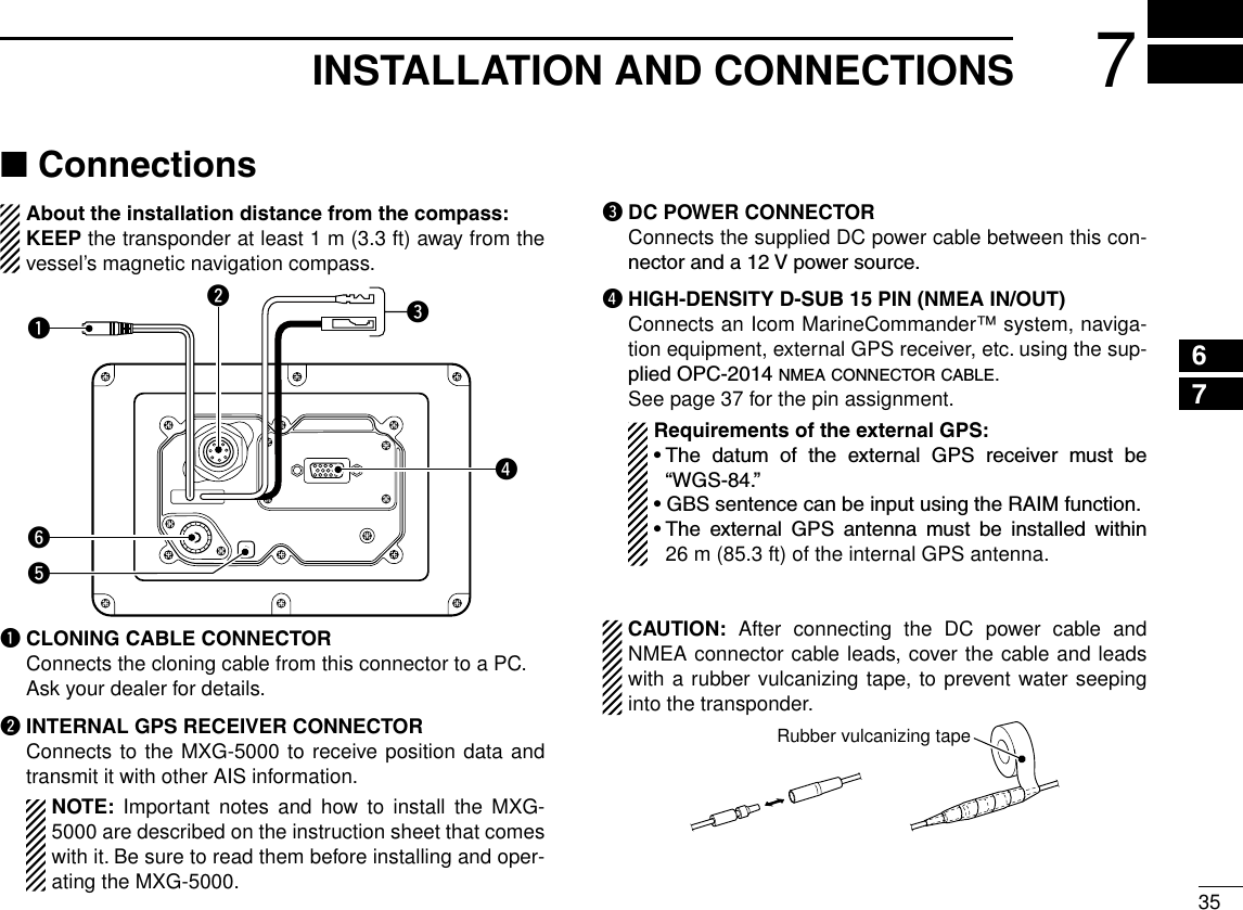
![103PREPARATIONNew2001■ Initial setting mode (Continued)D Internal/External GPS Antenna PositionSetthesemeasurementstoindicatetheinternaland/orexter-nal GPS antenna position on the vessel.•InternalGPSantenna :The GPS antenna which is connected tothe [GPS] connector.•ExternalGPSantenna:The GPS antenna which is connected to one of the NMEA lines. (p. 37)q Push [∫] or [√] to select “A,” “B,” “C” or “D.” •A : Bow to Antenna •B : Stern to Antenna •C : Port side to Antenna •D : Starboard side to Antenna •Push[CLEAR] to cancel and return to the previous screen.w Push [Ω] or [≈] to input the value into that item. A and B : Between 0 and 511 meters (0 and 1676.5 feet) C and D : Between 0 and 63 meters (0 and 206.6 feet)e Repeat steps q and w to input other values.r Push [ENT] to save and return to the Initial setting mode.[CLEAR][ENT][∫], [√],[Ω], [≈]To show the external GPS antenna set screen, select “Set EXT GPS POS” in the “Initial Setting” mode. (p. 9)D Type of ShipSelect your vessel type.➥ P ush [∫] or [√] to select your vessel type from the list, then push [ENT] to save and return to the Initial setting mode.[ENT][∫][√]• Type of Ship List30 Fishing 52 Tugs31 Towing 53 Port tender32 Towing & two < 200m 54 Vesselswithantipollution33 Engaged in Dredging 55 LawenforcementsVessel34 Engaged in Diving 58 Medical Transports35 Engaged in Military 59 Ships RR Resolution NO1836 Sailing 60 Passenger Ship37 Pleasure Craft 70 Cargo Ship50 Pilot 80 Tanker51 Search&RescueVesselThis screen shows the inter-nal GPS antenna set screen.](https://usermanual.wiki/ICOM-orporated/322800/User-Guide-1517361-Page-18.png)
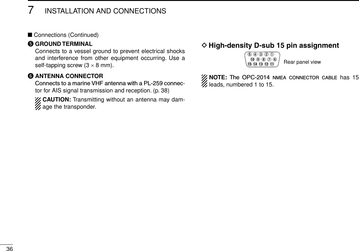
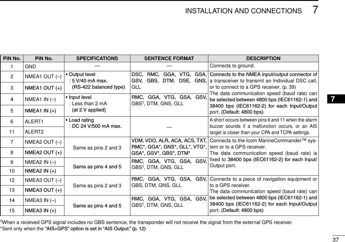
![113PREPARATIONNew200112345678910111213141516D NMEA Input/Output ports• NMEA1/NMEA2/NMEA3 data speedThe data communication speed (baud rate) can be set for eachInput/Outputport;NMEA1andNMEA3.NOTE: The data communication speed of NMEA2 is fixed to38400bps.NMEA2isused for communication between the transponder and the Icom MarineCommander™ sys-tem or a GPS receiver.q Push [∫] or [√] to select “NMEA1” or “NMEA3.” •NMEA1 : Used for communication between the transponder and atransceiveroraGPSreceiver.(Default:4800bps) •NMEA3 : Used for communication between the transponder and a navigational equipment or a GPS receiver. (Default:4800bps) •Youcannotselect“NMEA2.”w Push [ENT] to select the data communication speed be-tween4800bpsand38400bpsintothatitem. •Youcanalsoselecttheoptionbypushing[Ω] or [≈].e Repeat steps q and w to set another port.r Push [CLEAR] to save and return to the Initial setting mode.[CLEAR][ENT][∫], [√],[Ω], [≈]• GPS Input1/GPS Input2/GPS Input3Set the NMEA1, NMEA2 and NMEA3 Input ports’ capability.q Push [∫] or [√] to select “GPS Input1,” “GPS Input2” or “GPS Input3.” •“GPS Input1” is for the NMEA1, “GPS Input2” is for the NMEA2 and “GPS Input3” is for the NMEA3 ports setting.w Push [ENT] to toggle this function ON or OFF. •You can also turn thefunction ON bypushing [≈], or OFF by pushing [Ω]. ON : The GPS information that is received from the ex-ternal GPS receiver of the selected port is sent to the transponder. (Default for “GPS Input2” and “GPS Input3”) OFF : The GPS information that is received from the ex-ternal GPS receiver of the selected port is not sent to the transponder. (Default for “GPS Input1”)e Repeat steps q and w to set other ports’ capability.r Push [CLEAR] to save and return to the Initial setting mode.[CLEAR][ENT][∫], [√],[Ω], [≈]](https://usermanual.wiki/ICOM-orporated/322800/User-Guide-1517361-Page-19.png)
![123PREPARATIONNew2001■ Initial setting modeDNMEAInput/Outputports(Continued)• AIS OutputSet the NMEA2 Output port’s capability.This function should normally be set to “AIS.”q Push [∫] or [√] to select “AIS Output.”w Push [ENT]toselecteither“AIS”or“AIS+GPS.” •Youcanalsoselecttheoptionbypushing[Ω] or [≈]. AIS : The NMEA2 Output port sends only the AIS information to the connected device. (Default) AIS+GPS :The NMEA2 Output port sends both the AISand GPS information to the connected device. This setting is recommended for use in an area where there are few vessels. In an area crowded with AIS equipped vessels, some AIS information may be missed.e Push [CLEAR] to save and return to the Initial setting mode.[CLEAR][ENT][∫], [√],[Ω], [≈]• Remote IDSet a Remote ID number between 80 and 89.The Remote ID is included in the sentence of the format for the Icom own NMEA.q Push [∫] or [√] to select “Remote ID.”w Push [Ω] or [≈] to set a Remote ID number between 80 and 89.e Push [CLEAR] to save and return to the Initial setting mode.[CLEAR][∫], [√],[Ω], [≈]](https://usermanual.wiki/ICOM-orporated/322800/User-Guide-1517361-Page-20.png)
![133PREPARATIONNew200112345678910111213141516D Name and Call Sign settingsq Push [∫] or [√] to select the “Set Name” or “Set Call Sign” that you want to program, then push [ENT] to enter the set-ting mode.[ENT][∫][√]w Push [∫], [√], [Ω] or [≈] to select the desired character in the table, then push [ENT] to input it. •Select“ ,” then push [ENT] to move the cursor forward. •Select“ ,” then push [ENT] to move the cursor backward. •Select“SPACE,” then push [ENT] to input a space. •Select“DELETE,” then push [ENT] to delete a character. •Push[CLEAR] to cancel and return to the previous screen.[CLEAR][ENT][∫], [√],[Ω], [≈]e Repeat step w to input all characters.r Push [∫], [√], [Ω] or [≈] to select “FINISH,” then push [ENT] to save and return to the Initial setting mode.[ENT][∫], [√],[Ω], [≈]](https://usermanual.wiki/ICOM-orporated/322800/User-Guide-1517361-Page-21.png)
![New200114New2001BASIC OPERATION4■ Turning power ONIMPORTANT: BE SURE to connect the GPS receiver to the transponder before turning the power ON. (p. 35)q Hold down [POWER•BRILL] for 1 second to turn ON the power. •A long beep sounds, and the opening screen appears.[POWER•BRILL]w The opening screen displays the results of the ROM, RAM and backup data test, “OK” or “NG” (No Good). •If “NG” is displayed, hold down [POWER•BRILL] for 1 second to turn OFF the power, then ON again to reset the transponder. If there is no change, contact your dealer or service center.e After the opening test is completed, the MMSI code ap-pears, if the code has already been set. •“NoMMSI”appearswhennoMMSIcodeisset. (p. 7)r The GPS search display appears while searching for a GPS satellite. •Whilesearching,theGPSinformationscreencanbedisplayedby pushing [ENT], or you can enter the Menu mode by pushing [MENU]. (pp. 28, 31)t When the GPS receiver receives signals from a satellite, the transponder automatically displays the position data on the plotter display. (p. 15)](https://usermanual.wiki/ICOM-orporated/322800/User-Guide-1517361-Page-22.png)
![New2001154BASIC OPERATIONNew200112345678910111213141516■ Display backlight and contrast settingsYou can adjust the display backlight and contrast settings.The display backlight lights the function display and keys, and is convenient for nighttime operation.Also, you can adjust the display contrast between objects and the background.qPush [POWER•BRILL] to display the popup screen to ad-just the display backlight and contrast level.w Push [∫] or [√] to select “Backlight” or “Contrast,” which-ever one you want to adjust.e Push [Ω] or [≈] to adjust the level. •Backlight:Between1and7,orOFF •Contrast :Between1and8r Push [ENT] to save the settings and turn OFF the popup screen. •Ifnokeyoperationisperformedfor5seconds,the backlight and contrast levels are saved, and the popup screen automatically turns OFF.Convenient!Each push of [POWER•BRILL] after the popup screen is dis-played, also adjusts the display backlight level.■ Plotter display operationWhen the plotter display is selected, the display range and the icons of the AIS targets appear. You can change the display range and type (North up or COG up) to suit your operating style.qPush [DISP MODE] several times to select the plotter dis-play.w Push [∫] or [√] to select the desired display range. •0.125,0.25,0.5,0.75,1.5,3,6,12,24nm(nauticalmiles)areselectable.e Push [≈] to sequentially select each AIS target icon clos-est to your vessel (orwaypoint,ifitisset;seepage24forsetting detail), in sequence. Or, push [Ω] to select each AIS target (or waypoint) icon farthest from your vessel, in sequence. •Atargetboxwillappeararoundtheselectedtarget(orwaypoint)icon. • Shows the range and bearing information from your vessel to the selected AIS target. • Shows the CPA (Closest Point of Approach) and TCPA (Time to CPA) information of the selected AIS target whose CPA is less than 6 nm (nautical miles) and TCPA is less than 60 minutes to your vessel.r Push [ENT] to display it’s detail screen. (p. 17)NOTE: The alarm buzzer sounds when a malfunction oc-curs or an AIS target is closer than your CPA and TCPA settings,dependingonthepresetting.(pp.29,30,33,44)➥ To stop the alarm buzzer, push [CLEAR]. •If the popup screen is displayed, push [CLEAR] again to turn it OFF.](https://usermanual.wiki/ICOM-orporated/322800/User-Guide-1517361-Page-23.png)
![164BASIC OPERATIONNew2001■ Plotter display operation (Continued)D Setting the display type (North up/COG up)Select the display type between “North up” and “COG up.”q Push [MENU] to enter the Menu mode.w Push [∫] or [√]toselect“Northup/COGup,”thenpush[ENT].e Push [ENT] to select either “North up” or “COG up.” •Youcanalsoselecttheoptionbypushing[Ω] or [≈]. North up : The top of the plotter display represents North. COG up : The top of the plotter display represents the di-rection your course is heading.r Push [CLEAR] to save and return to the Menu mode.t Push [CLEAR] to exit the Menu mode.[CLEAR][ENT][MENU][∫], [√],[Ω], [≈]■ Target list display operationThe target list display shows all AIS targets being detected by the transponder, including their range and bearing infor-mation.The AIS target data is sorted by the distance from your ves-sel, and the closest target is located on the top of the list.Their range and bearing information is automatically updated every 5 seconds, then the AIS target data is sorted.qPush [DISP MODE] several times to select the target list display.w Push [∫] or [√] to select the desired AIS target.e Push [ENT] to display it’s detail screen. (p. 17)NOTE: The alarm buzzer sounds when a malfunction oc-curs or an AIS target is closer than your CPA and TCPA settings,dependingonthepresetting.(pp.29,30,33,44)➥ To stop the alarm buzzer, push [CLEAR]. •Ifthepopupscreenisdisplayed,push[CLEAR] again to turn it OFF.](https://usermanual.wiki/ICOM-orporated/322800/User-Guide-1517361-Page-24.png)
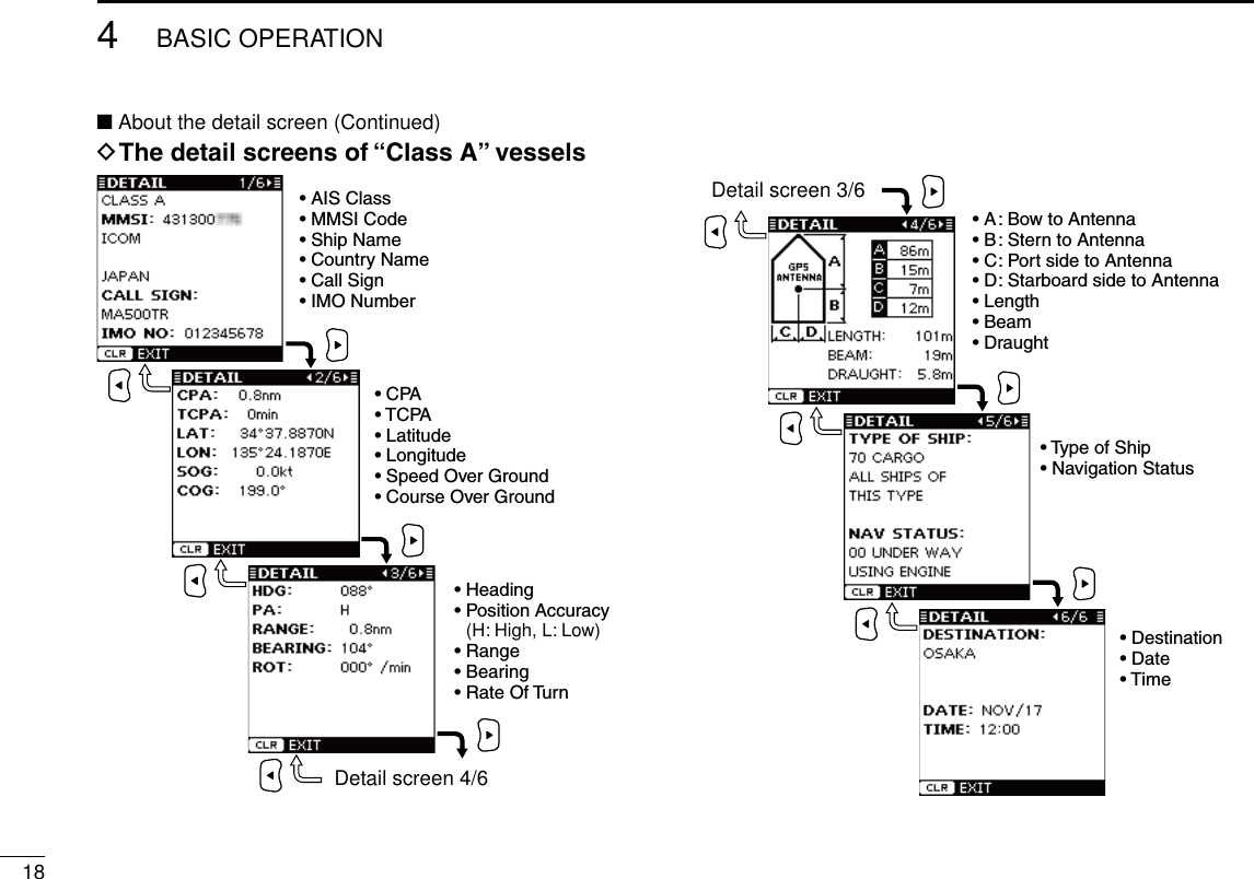
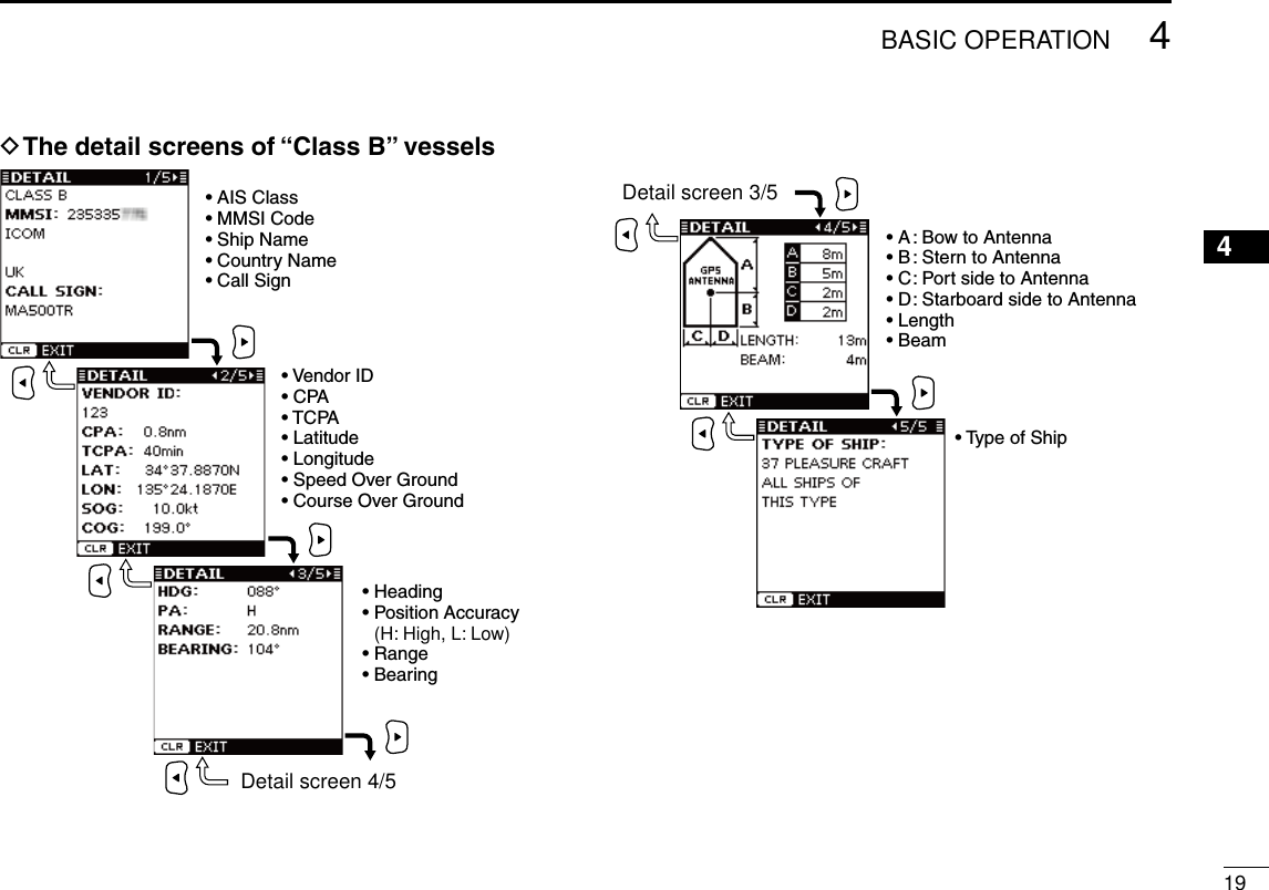
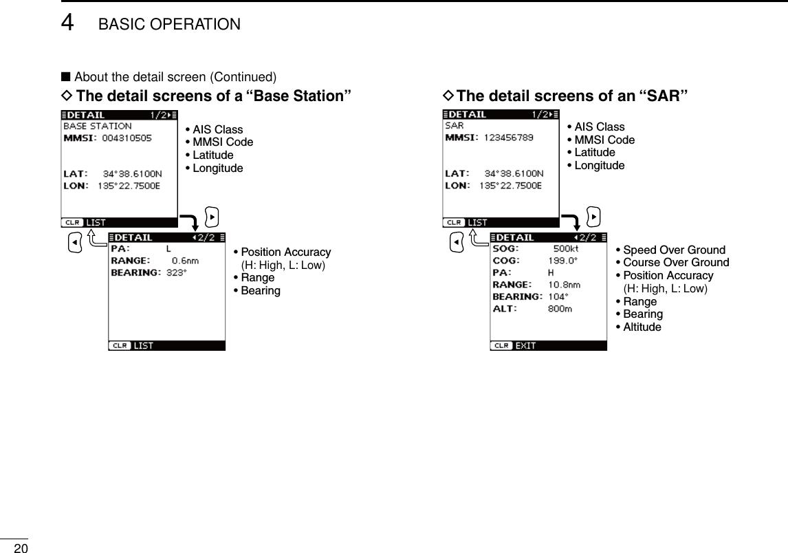
![174BASIC OPERATIONNew200112345678910111213141516■ Danger list display operationThe danger list display shows any dangerous target whose CPA (Closest Point of Approach) distance is less than 6 nm (nautical miles), and TCPA (Time to CPA) time is less than 60 minutes to your vessel.The dangerous target data is sorted by CPA or TCPA (you can choose either; see step q).Their CPA and TCPA information is automatically updated every 5 seconds, then the dangerous target data is sorted.qPush [DISP MODE] several times to select the danger list display. •Push [Ω] to sort the AIS target data by CPA. •Push [≈] to sort the AIS target data by TCPA.w Push [∫] or [√] to select the desired AIS target.e Push [ENT] to display it’s detail screen. (See to the right)NOTE: The alarm buzzer sounds when a malfunction oc-curs or an AIS target is closer than your CPA and TCPA settings,dependingonthepresetting.(pp.29,30,33,44)➥ To stop the alarm buzzer, push [CLEAR]. •Ifthepopupscreenisdisplayed,push[CLEAR] again to turn it OFF.■ About the detail screenThe detail screen shows information about the selected AIS target. The contents differ, depending on the AIS class.In the detail screen, pushing [CLEAR] returns to the previ-ous screen, which was displayed before entering the details screen.See pages 18 to 21 for the detail screen of each AIS class.](https://usermanual.wiki/ICOM-orporated/322800/User-Guide-1517361-Page-25.png)
![New2001224BASIC OPERATIONNew2001When a transceiver* is connected to the transponder, you can transmit an Individual DSC call without needing to enter the vessel’s MMSI code, by simply selecting it’s AIS target and the voice channel you wish to use on the transponder.The transceiver will use the transponder’s data information and make the DSC call on channel 70, then wait for the target vessel to acknowledge it. After receiving the acknowledge-ment ‘Able to comply,’ use the transceiver to communicate with the target vessel on the predetermined voice channel.* See the leaflet that comes with the transponder for details of the trans-ceivers which can operate with this function.Seepages39and40forconnectinginstructions.NOTE: The data communication speed (baud rate) of NMEA1 must be set to 4800 bps to send an IndividualDSC call using the transponder. (p. 11)q Select the desired AIS target on the plotter, target list or danger list display. (pp. 15–17) •Youcanalsogotothenextstepwheneverthedetailscreenofthe AIS target is displayed.w Push [DSC] to display the voice channel selection screen, then push [∫] or [√] to select the desired voice channel. •Voicechannelsarealreadypresetintothetransponderinrecom-mended order.[DSC][∫][√] NOTE: When a base station is selected in step q, a voice channel will be specified by the base station, therefore you cannot change the channel. The tran-sponderwilldisplay“VoiceChannelisspeciedbytheBase station,” in this case.e Push [DSC] to make the Individual DSC call. •“DSC Transmitting” appears. •IfChannel70isbusy,thetransceiverstandsbyuntilthechannelbecomes clear. •If the transceiver cannot make the call, “DSC Transmission FAILED” appears.r After making the Individual DSC call, “DSC Transmission COMPLETED” appears.t Push [CLEAR] to return to the previous screen before you entered the voice channel selection screen in step w.y After receiving the acknowledgement from the AIS target, use the transceiver to communicate. See the transceiver’s manual for details.■ Individual DSC call (Possible only when a transceiver is connected)](https://usermanual.wiki/ICOM-orporated/322800/User-Guide-1517361-Page-30.png)
![235OTHER FUNCTIONSNew200112345678910111213141516■ MessageD Receiving a messageA safety-related message of up to 161 characters can be re-ceived from an AIS equipped vessel in the area.When a message is received, a beep sounds three times, and the message icon appears on the plotter display. (The message icon does not appear on the target list or danger list display.)The contents of the message can be checked in the receive message log, as described to the right.The message icon stays on the plotter display as long as the unread message is stored in the RX log memory.NOTE: The transponder automatically stores the received messages in the RX log memory. (See to the right)AppearsPlotter displayD Message logsThe transponder automatically stores the last 20 received messages in the log memory.The oldest message is automatically deleted when a new message is received.q Push [MENU] to enter the Menu mode.w Push [∫] or [√] to select “Message,” then push [ENT].e Push [∫] or [√] to select “RX Log,” then push [ENT].r Push [∫] or [√] to select the message that you want to read, then push [ENT]. •Thecontentsoftheselectedmessagearedisplayed.t Push [CLEAR] to return to the previous screen.y Push [CLEAR] three times to exit the Menu mode.](https://usermanual.wiki/ICOM-orporated/322800/User-Guide-1517361-Page-31.png)
![245OTHER FUNCTIONSNew2001 New2001■ WaypointD Display a waypoint listUp to 100 waypoints can be stored in the waypoint list.q Push [MENU] to enter the Menu mode.w Push [∫] or [√] to select “Waypoint,” then push [ENT].e Push [∫] or [√] to select “List,” then push [ENT].r Push [∫] or [√] to select the desired waypoint. •Push [Ω] to sort the waypoint data by Name. •Push [≈] to sort the waypoint data by Range.t Push [ENT] to display the detail screen of the selected waypoint.y Push [CLEAR] to return to the previous screen.u Push [CLEAR] three times to exit the Menu mode.D Add a waypointThe position information that you want to memorize can be added as a waypoint.q Push [MENU] to enter the Menu mode.w Push [∫] or [√] to select “Waypoint,” then push [ENT].e Push [∫] or [√] to select “Add,” then push [ENT]. •Yourcurrentpositioninformationisdisplayed.r Push [∫] or [√] to select “Name,” then push [ENT].t Push [∫], [√], [Ω] or [≈] to select the desired character in the table, then push [ENT] to input it. •Select“ ,” then push [ENT] to move the cursor forward. •Select“ ,” then push [ENT] to move the cursor backward. •Select“SPACE,” then push [ENT] to input a space. •Select“DELETE,” then push [ENT] to delete a character. •Push[CLEAR] to cancel and return to the previous screen.[CLEAR][ENT][∫], [√],[Ω], [≈]y Repeat step t to input a waypoint name of up to 10 char-acters.u Push [∫], [√], [Ω] or [≈] to select “FINISH,” then push [ENT] to set and return to the previous screen.](https://usermanual.wiki/ICOM-orporated/322800/User-Guide-1517361-Page-32.png)
![New2001255OTHER FUNCTIONSNew200112345678910111213141516i Push [∫] or [√] to select “LAT:,” then push [ENT].o Push [∫], [√], [Ω] or [≈] to set the desired latitude data in the table, then push [ENT] to input it. •Select“ ,” then push [ENT] to move the cursor forward. •Select“ ,” then push [ENT] to move the cursor backward. •Select“N,” then push [ENT] to input N; North latitude. •Select“S,” then push [ENT] to input S; South latitude. •“W” and “E” cannot be input. •Push[CLEAR] to cancel and return to the previous screen.[CLEAR][ENT][∫], [√],[Ω], [≈]!0 Push [∫], [√], [Ω] or [≈] to select “FINISH,” then push [ENT] to set and return to the previous screen.!1 Push [∫] or [√] to select “LON:,” then push [ENT].!2 Push [∫], [√], [Ω] or [≈] to set the desired longitude data in the table, then push [ENT] to input it. •Select“ ,” then push [ENT] to move the cursor forward. •Select“ ,” then push [ENT] to move the cursor backward. •Select“W,” then push [ENT] to input W; West longitude. •Select“E,” then push [ENT] to input E; East longitude. •“N” and “S” cannot be input. •Push[CLEAR] to cancel and return to the previous screen.[CLEAR][ENT][∫], [√],[Ω], [≈]!3 Push [∫], [√], [Ω] or [≈] to select “FINISH,” then push [ENT] to set and return to the previous screen.!4 Push [∫] or [√]toselect“SAVE,”thenpush[ENT] to save the waypoint data and return to the “WAYPOINT” screen. •Push[CLEAR] to cancel and return to the previous screen.[CLEAR][ENT][∫][√]!5 Push [CLEAR] twice to exit the Menu mode.Convenient!Each time you hold down of [MOB] also adds a waypoint. See page 26 to edit the waypoint data.](https://usermanual.wiki/ICOM-orporated/322800/User-Guide-1517361-Page-33.png)
![265OTHER FUNCTIONSNew2001■ Waypoint (Continued)D Edit a waypointA waypoint’s name, latitude and longitude data can be ed-ited.q Push [MENU] to enter the Menu mode.w Push [∫] or [√] to select “Waypoint,” then push [ENT].e Push [∫] or [√] to select “Edit,” then push [ENT]. •The “EDIT WAYPOINT” list is displayed.r Push [∫] or [√] to select the desired waypoint. •Push [Ω] to sort the waypoint data by Name. •Push [≈] to sort the waypoint data by Range.t Push [ENT] to enter the edit item selection screen.y Push [∫] or [√] to select the top item (waypoint name), then push [ENT].u Enter a waypoint name, latitude data and longitude data, as described in steps t to !3 of “D Add a Waypoint” on pages24and25.i Push [∫] or [√]toselect“SAVE,”thenpush[ENT] to save the edited data and return to the “EDIT WAYPOINT” list screen. •Push[CLEAR] to cancel and return to the previous screen.[CLEAR][ENT][∫][√]o Push [CLEAR] three times to exit the Menu mode.](https://usermanual.wiki/ICOM-orporated/322800/User-Guide-1517361-Page-34.png)
![275OTHER FUNCTIONSNew200112345678910111213141516D Delete a waypointA waypoint can be deleted from the waypoint list.q Push [MENU] to enter the Menu mode.w Push [∫] or [√] to select “Waypoint,” then push [ENT].e Push [∫] or [√] to select “Delete,” then push [ENT]. •The “DELETE WAYPOINT” list is displayed.r Push [∫] or [√] to select the desired waypoint. •Push [Ω] to sort the waypoint data by Name. •Push [≈] to sort the waypoint data by Range.t Push [ENT] to display the detail screen of the selected way-point.y Push [ENT] to display the confirmation screen.u Push [Ω] or [≈] to select “OK,” then push [ENT] to de-lete the selected waypoint data and return to the “DELETE WAYPOINT” list screen. •Select“Cancel”tocanceldeleting.[ENT][≈][Ω]i Push [CLEAR] three times to exit the Menu mode.■ Lost targetA vessel is regarded as a “Lost target” after a specified period of time has passed since the vessel last transmitted data, as described below.The “Lost target” icon disappears from the plotter display 6minutesand40secondsafterthevesselwasregardedasa“Lost target.” (default) Ask your dealer for details.The criteria to become a Lost target (Default):Vesseltype Except Class B Class B1Except Class B : Vessel is at anchor, mooredand moving less than 3 knotsClassB :Vesselismovinglessthan2 knots18 min. 18 min.2Vessel is at anchor, moored and movingmore than 3 knots 1 min. N/A3Vessel is moving between 0 and 14 knots(ExceptClassB),orbetween2and14knots(Class B)1 min. 3 min.4Vessel is moving between 0 and 14 knotswhile changing course 1 min. N/A5Vesselismovingbetween14and23knots 36 sec. 90 sec.6Vesselismovingbetween14and23knotswhile changing course 36 sec. N/A7Vesselismovingmorethan23knots 12 sec. 30 sec.8Vesselismovingmorethan23knotswhilechanging course 12 sec. N/A](https://usermanual.wiki/ICOM-orporated/322800/User-Guide-1517361-Page-35.png)
![28New2001New2001MENU MODE OPERATION6■ Generalq Push [MENU] to enter the Menu mode.w Push [∫] or [√] to select the desired item, then push [ENT].e Select the desired option or check the screen contents. Theproceduresaredescribedonpages29to34. •Someitemsare not described in this section. See the list to the right for the specified pages.r Repeat steps w and e to select or check other items.t Push [CLEAR] to exit the Menu mode.[CLEAR][ENT][MENU][∫][√]■ Menu mode itemsThe Menu mode contains the following items.Item Ref. Item Ref.North up/COG up* p. 16 User SettingCPA/TCPA •RCVMSGBUZZ p. 33 •Alarm p. 29 •InternalGPS p. 33 •SlowWarn p. 29 - SBAS Function p.34 •CPA,TCPA p. 30 - SBAS Search p.34Message - SBAS Satelite p.34 •RXLog* p. 23 Initial SettingWaypoint •SetMMSI* pp. 7, 9 •List* p.24 •SetName*pp. 9, 13 •Add* p.24 •SetCallSign*pp. 9, 13 •Edit* p. 26 •SetINTGPSPOS* p. 10 •Delete* p. 27 •Set EXT GPS POS* p. 10Own Static p. 30 •SetTypeofShip* p. 10Own Dynamic p. 31 •SetInput/Output* p. 11GPS Information p. 31 Channel Information p.34Alarm Status p. 32 DiagnosticsUser Setting •MonitorTest* p.44 •KeyBeep p. 32 •TransponderTest* p.45 •AlarmBuzzer p. 33 •VersionInformation* p.45*These items are not described in this section. See the specified page.](https://usermanual.wiki/ICOM-orporated/322800/User-Guide-1517361-Page-36.png)
![New2001296MENU MODE OPERATIONNew200112345678910111213141516D CPA/TCPA• AlarmYou can turn the collision alarm function ON or OFF.q Push [∫] or [√] to select “Alarm.”w Push [ENT] to toggle this function ON or OFF. •You can also turn ONthe function bypushing [≈], or OFF by pushing [Ω]. ON : “COLLISION ALARM” appears on the display, and the alarm buzzer sounds* repeatedly when an AIS target is closer than your CPA and TCPA settings, as explained to page 30. (default) * The alarm buzzer sounds only when the alarm buzzer function is turned ON. (p. 33) OFF : The collision alarm function is OFF.e Push [CLEAR] to save and return to the Menu mode.[CLEAR][ENT][∫], [√],[Ω], [≈]• Slow WarnThe GPS receiver calculated COG data of a vessel that is at anchor or drifting is unreliable, and therefore the CPA and TCPA data may not be calculated correctly. If a vessel is anchored in your alarm zone, the unreliable data can cause the collision alarm to sound many times, even if there is no real danger. To prevent this, when the anchored vessel’s SOG is less than this set value, the Slow Warn function assumes that vessel’s COG is fixed towards your vessel and an alarm will sound.q Push [∫] or [√] to select “Slow Warn.”w Push [Ω] or [≈]toinputthevaluebetween0.1and4.9kt(in 0.1 kt steps), or select OFF. (default: 1.0 kt)e Push [CLEAR] to save and return to the Menu mode.[CLEAR][∫], [√],[Ω], [≈]NOTE: If other vessels at anchor or drifting come into your alarm zone, the Slow Warn alarm will sound again. Only if the previous vessel disappears from the Dangerous List (pp. 6, 17), and then re-enters the list, can a new Slow Warn or regular alarm sound, depending on the vessels SOG, or CPA and TCPA. The Slow Warn function operates in the same way if your vessel is at anchor and other ves-sels enter your alarm zone area.](https://usermanual.wiki/ICOM-orporated/322800/User-Guide-1517361-Page-37.png)
![306MENU MODE OPERATIONNew2001■ Menu mode itemsDCPA/TCPA(Continued)• CPA, TCPAEnter CPA (Closest Point of Approach) and TCPA (Time to CPA) values.These settings help you find a dangerous target to avoid a collision. The icon blinks on the plotter display and/or thealarm buzzer sounds, when the AIS target is closer than your CPA and TCPA settings.q Push [∫] or [√] to select either “CPA” or “TCPA.”w Push [Ω] or [≈] to input the value into that item. •CPA :Between0.1and6.0nm(in0.1nmsteps) (default: 1.5 nm) •TCPA:Between1and60minutes(in1minutesteps) (default: 20 min)e Repeat steps q and w to input the value into the other item.r Push [CLEAR] to save and return to the Menu mode.[CLEAR][ENT][∫], [√],[Ω], [≈]D Own StaticThis screen shows your static vessel information such as MMSIcode,VesselName,CallSign,Internal/ExternalGPSantenna position and Type of Ship.q When the Own Static screen is displayed, push [≈] to se-lect the next page, or push [Ω] to select the previous page.w Push [CLEAR] to return to the Menu mode.](https://usermanual.wiki/ICOM-orporated/322800/User-Guide-1517361-Page-38.png)
![316MENU MODE OPERATIONNew200112345678910111213141516D Own DynamicThis screen shows your dynamic vessel information such as Latitude and Longitude data, SOG, COG, GPS receiver type, UTC date and time, PA, RAIM (Receiver Autonomous Integ-rity Monitoring) function availability and Latitude and Longi-tude error data.•Aninternal GPShasnoRAIMfunction.Whentheinternal GPSisused, “RAIM,” “LAT ERROR” and “LON ERROR” are not displayed.•AnexternalGPSrequiresaRAIMfunction. When the external GPS is used, “RAIM,” “LAT ERROR” and “LON ERROR” are displayed.q When the Own Dynamic screen is displayed, push [≈] to select the next page, or push [Ω] to select the previous page.w Push [CLEAR] to return to the Menu mode.D GPS InformationThe GPS Information screen shows the viewable GPS satel-lite’s information, when the internal or external* GPS receiver is connected.* Only when the transponder receives the sentence format “GSA”or“GSV”fromtheexternalGPSreceiver.q When the GPS Information screen is displayed, push [≈] to select the next page, or push [Ω] to select the previous page. •Theiconsofthesatellites being used, blink.w Push [CLEAR] to return to the Menu mode.SAT : Satellite numberLEVEL : Signal strength levelThe GPS antenna of your vessel is located in the center of the North, South, East and West screen, and the visible GPS satellite icons are displayed.When a non-differential GPS receiver is connected, PA is normally ‘L.’ However, if the values of “LAT ERROR” and “LON ERROR” are less than 5.0 meters (16.4 feet), PAchanges to ‘H.’ When a differential GPS re-ceiver is connected, PA is normally ‘H.’ However, if the values of “LAT ERROR” and “LON ERROR” are more than15.0meters(49.2feet),PA changes to ‘L.’](https://usermanual.wiki/ICOM-orporated/322800/User-Guide-1517361-Page-39.png)
![326MENU MODE OPERATIONNew2001■ Menu mode items (Continued)D Alarm StatusThe Alarm Status screen shows the type, date and time of the last 25 malfunctions that were detected.Even if the alarm buzzer function is turned OFF, the alarm status is displayed here. (p. 33)q When the Alarm Status screen is displayed, push [∫] or [√] to scroll the screen.w Push [CLEAR] to return to the Menu mode.Alarm typeDateTime[CLEAR][∫][√]• Description of the Alarm typeAlarm type DescriptionGPS Appears when “GPS Malfunction” is detected.RX Appears when “RX Malfunction” is detected.CH A Appears when “CH A Noise Level Malfunction” is detected.CH B Appears when “CH B Noise Level Malfunction” is detected.TX Appears when “TX Malfunction” is detected.ANT Appears when “Antenna Open or Short Malfunction” or“AntennaHighVSWRMalfunction”isdetected.D User SettingThe User setting mode allows you to set the seldom-changed settings, and you can “customize” the transponder operation to suit your preferences and operating style.q Push [MENU] to enter the Menu mode.w Push [∫] or [√] to select “User Setting,” then push [ENT].e Push [∫] or [√] to select the desired item, then push [ENT].r Select the desired option, shown in the Menu below. The procedures are described to the right and continued on the next page.t Repeat steps e and r to select other items.y Push [CLEAR] to save and return to the Menu mode.u Push [CLEAR] to exit the Menu mode.[CLEAR][ENT][∫][√][MENU]<SETTING ITEMS>• Key BeepYou can select the silent operation, or you can have confirma-tion beeps sound when you push a key.➥ Push [ENT] to toggle this function ON or OFF.* ON : A beep sounds when pushing a key. (default) OFF : The key beep is OFF. (Silent operation)](https://usermanual.wiki/ICOM-orporated/322800/User-Guide-1517361-Page-40.png)
![336MENU MODE OPERATIONNew200112345678910111213141516• Alarm BuzzerTurn the alarm buzzer function ON or OFF.➥ Push [ENT] to toggle this function ON or OFF.* ON : The alarm buzzer sounds when a malfunction oc-curs or an AIS target is closer than your CPA and TCPA settings*. (default) * The alarm buzzer sounds only when the collision alarm function is turned ON. (p. 29) OFF : The alarm buzzer is OFF.• Received Message Buzzer (RCV MSG BUZZ)Turn the received message buzzer function ON or OFF.➥ Push [ENT] to toggle this function ON or OFF.* ON : The buzzer sounds three times when a message is received. (default) OFF : The received message buzzer is OFF.* You can also turn ON the function by pushing [≈], or OFF by pushing [Ω].• Internal GPSThe Internal GPS setting mode allows you to set the internal GPS settings.q Push [MENU] to enter the Menu mode.w Push [∫] or [√] to select “User Setting,” then push [ENT].e Push [∫] or [√] to select “Internal GPS,” then push [ENT].r Push [∫] or [√] to select the desired item, then push [ENT].t Select the desired option, shown in the Menu below. The procedures are described to the right and continued on the next page.y Repeat steps r and t to select other items.u Push [CLEAR] to save and return to the User Setting mode.i Push [CLEAR] twice to exit the Menu mode.[CLEAR][ENT][∫][√][MENU]](https://usermanual.wiki/ICOM-orporated/322800/User-Guide-1517361-Page-41.png)
![346MENU MODE OPERATIONNew2001■ Menu mode itemsD User Setting (Continued)<SETTING ITEMS>- SBAS (Satellite Based Augmentation System) FunctionThe SBAS transmits signals to correct errors and improve accuracy and reliability in data received from regular GPS satellites. When this function is ON, the transponder uses the corrected data.➥ Push [ENT] to toggle this function ON or OFF. •You can also turn ONthe function bypushing [≈], or OFF by pushing [Ω]. ON : The SBAS function is ON. (default) OFF : The SBAS function is OFF.- SBAS SearchSet the SBAS search function to “Manual” or “Auto.”This function should normally be set to “Auto.”➥ Push [ENT] to select either “Manual” or “Auto.” •Youcanalsoselecttheoptionbypushing[Ω] or [≈]. Manual : You have to manually select the SBAS satellite. This option can be useful when your vessel is in an area where 2 satellite zones overlap. Auto : The transponder automatically searches for the SBAS satellite that is determined according to the position of your vessel. (default)- SBAS SatelliteWhen “Manual” option is selected in the SBAS Search item, you should manually select the SBAS Satellite which covers the zone your vessel is monitoring.➥ Push [Ω] or [≈] to select an SBAS Satellite number be-tween 120 and 138. (default: 120)D Channel informationThe channel information screen shows the channels 2087 and 2088 information in which safety-related messages are transmitted to, and received from, the AIS targets.The channel to be used is automatically set according to the message received from an AIS Base Station.➥ Push [CLEAR] to return to the Menu mode.[CLEAR]New2001](https://usermanual.wiki/ICOM-orporated/322800/User-Guide-1517361-Page-42.png)
![438MAINTENANCENew200112345678910111213141516PROBLEM POSSIBLE CAUSE SOLUTION REF.The transponder does not turn ON.•Badconnectionatthepowersource. •Check the connection to the transpon-der. p. 35Cannot transmit. •1 minute has not passed from turningON the transponder power.•Wait for 1 minute from turning ON thetransponder power. —The plotter display does not appear.•Theresults ofthe openingtestis“NG”(No Good).•The transponder is still searching forGPS satellites.•Holddown[POWER•BRILL] for 1 sec-ond to turn the power OFF, then push to turn it ON again to reset the transpon-der.•Wait until the transponder detects aGPS satellite.pp. 7, 14—The GPS search display does not disappear.•The GPS receiver is not connected tothe transponder.•Connect the GPS receiver to the tran-sponder. p. 35An error beep sounds after pushing [DSC].•AnAIStargetisnotselected.•A transceiver is not connected to thetransponder.•SelectthedesiredAIStargetordisplaythe detail screen of the AIS target.•Connectthetransceivertothetranspon-der.pp. 15, 16, 17p. 39The collision alarm does not sound.•The collision alarm function is OFF.•ThealarmbuzzerfunctionisOFF.•Turn ON the collision alarm function.•TurnONthealarmbuzzerfunction.p. 29p. 33■ TroubleshootingThe following chart is designed to help you correct problems which are not equipment malfunctions.If you are unable to locate the cause of a problem or solve it through the use of this chart, contact your nearest Icom Dealer or Service Center.](https://usermanual.wiki/ICOM-orporated/322800/User-Guide-1517361-Page-51.png)
![448MAINTENANCENew2001■ Error messageError message is displayed when a malfunction occurs that has an error message programmed for it.Message contents DescriptionGPS MALFUNCTIONNO GPS DATAAppears when no GPS data is received.RX MALFUNCTIONNORCVAppears when the transponder receive cir-cuit has failed.RX MALFUNCTIONCHANOISELEVELAppears when the transponder receives excessively strong noise signals from an-other piece of navigation equipment on Channel A.RX MALFUNCTIONCHBNOISELEVELAppears when the transponder receives excessively strong noise signals from an-other piece of navigation equipment on Channel B.TX MALFUNCTIONNO TX POWERAppears when no RF power is output, or the transmit circuit has failed. TX MALFUNCTIONCONTINUOUS TXAppears when the protective circuit cuts off the AIS signal after 1 second of continuous transmission.ANT MALFUNCTIONOPEN OR SHORTAppears when the antenna is open or shorted.ANT MALFUNCTIONHIGHVSWRAppearswhenthehighVSWR*isdetected(the antenna is mismatched).*VoltageStandingWaveRatio ■ DiagnosticsThere are two types of diagnostic tests performed — Monitor test,TranspondertestandVersioninformation.• Monitor TestYou can check whether all LCD segments turn ON and OFF properly.q Push [MENU] to enter the Menu mode.w Push [∫] or [√] to select “Diagnostics,” then push [ENT].e Push [∫] or [√] to select “Monitor Test,” then push [ENT].r Push [∫] or [√] to select “All ON 2 Sec” or “All OFF 2 Sec,” then push [ENT]. •All ON 2 Sec : All LCD segments turn ON for 2 seconds. •All OFF 2 Sec : All LCD segments turn OFF for 2 seconds.t Push [CLEAR] to return to the “DIAGNOSTICS” screen.y Push [CLEAR] twice to exit the Menu mode.[CLEAR][ENT][∫][√][MENU]](https://usermanual.wiki/ICOM-orporated/322800/User-Guide-1517361-Page-52.png)
![458MAINTENANCENew200112345678910111213141516• Transponder TestYou can check whether the transponder units work properly.q Push [MENU] to enter the Menu mode.w Push [∫] or [√] to select “Diagnostics,” then push [ENT].e Push [∫] or [√] to select “Transponder Test,” then push [ENT].r ThescreenshowstheresultsoftheROM,RAM,RX/TXunit, antenna and GPS receiver tests; “OK” or “NG” (No Good).t Push [CLEAR] to return to the “DIAGNOSTICS” screen.y Push [CLEAR] twice to exit the Menu mode.[CLEAR][ENT][∫][√][MENU]• Version InformationYou can check the version information of SW (Software), FI (Function Image) and the Internal GPS receiver.q Push [MENU] to enter the Menu mode.w Push [∫] or [√] to select “Diagnostics,” then push [ENT].e Push [∫] or [√]toselect“VersionInformation,”then push [ENT].r The screen shows the version information of each item.t Push [CLEAR] to return to the “DIAGNOSTICS” screen.y Push [CLEAR] twice to exit the Menu mode.[CLEAR][ENT][∫][√][MENU]](https://usermanual.wiki/ICOM-orporated/322800/User-Guide-1517361-Page-53.png)


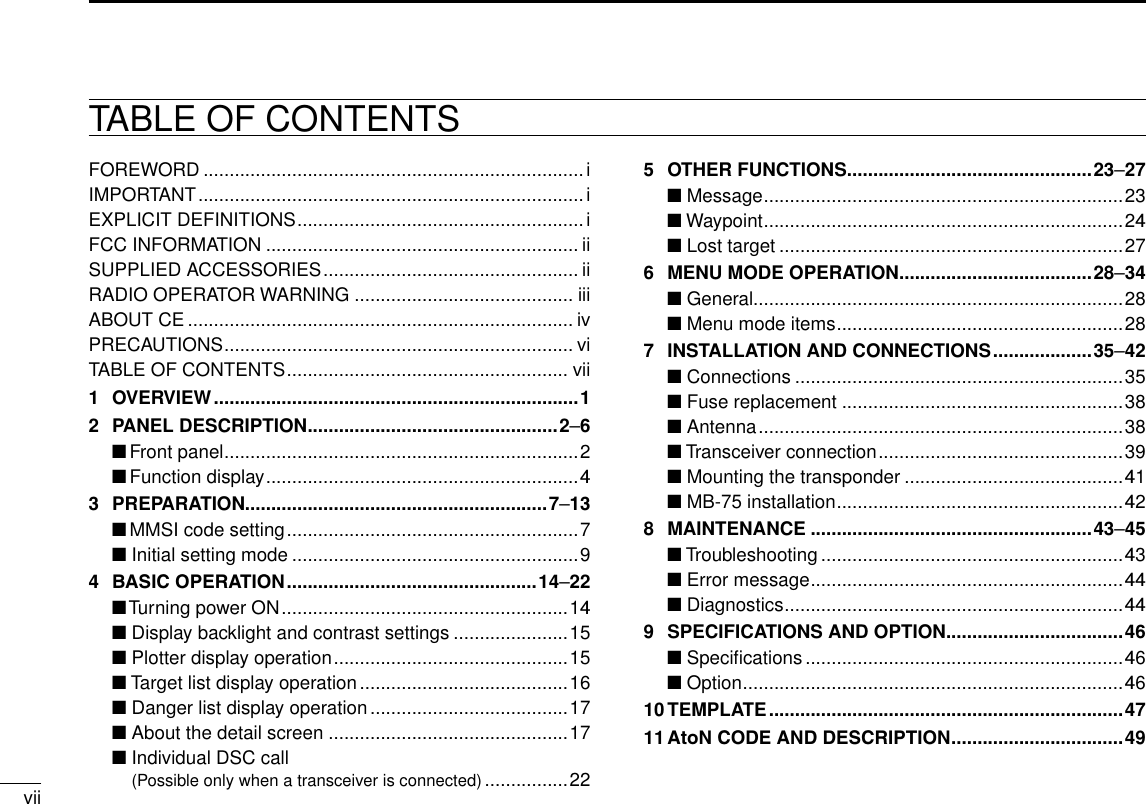
![About calculating positionThe GPS receiver acquires signals from GPS satellites. It calculates its position by the orbit information of the GPS satellites and needs to measure the distance between itself and three or more GPS satellites to obtain a reliable posi-tion. The GPS receiver acquires all available satellites when it is first powered up, powered off for a long time, or powered up again at a place a long way from when it was last powered off. Normally, it takes approximately 1 minute for de-termining a position.In places where the GPS signals cannot reach the GPS receiver, such as around tall buildings, it may show position errors (misplacement) or no position reading at all.As the satellites are continuously moving, mea-surement of the position or time by the GPS receiver may take a while, and/or no position reading can be made in some instances. Even if the GPS receiver acquires signals from three or more GPS satellites, it may take a longer time to determine a position depending on the satellite locations.About Almanac and Ephemeris DataTo reduce the time for calculating position, the GPS receiver stores the Almanac Data (the orbit course/orbital parameters of the satellites) in its internal memory. When the GPS receiver is left with the power OFF for a long time, it needs to acquire the Almanac Data again. In this case, the GPS receiver starts as a “cold” start.The GPS receiver stores Ephemeris Data of the satellite’s orbital course, and refers to this data when it is turned OFF for a short time.This is called a “hot” start, and uses the Ephem-eris Data that is valid to within less than 4 hours.1-1-32 Kamiminami, Hirano-ku, Osaka 547-0003, Japan. A-6747H-1EX-q Printed in Japan© 2009–2010 Icom Inc.Icom, Icom Inc. and the Icom logo are registered trademarks of Icom Incorporated (Japan) in Japan, the United States, United Kingdom, Germany, France, Spain, Russia and/or other countries.MarineCommander is a trademark of Icom Incorporated.ATTENTIONMOUNTINGLocation precisionThe GPS receiver automatically calculates its position when it acquires signals from three or more GPS satellites.The GPS satellite’s measurement error is about ±10 meters, however this can vary up to several hundred meters depending on the surrounding environment.When the GPS receiver is powered up again at a place a long way from when it was last pow-ered off, the first calculation of its position may be incorrect in some cases.The GPS information and its accuracy varies, depending on the GPS system being acquired, place and time.About NMEA sentenceAt times, the current position data cannot be received due to the GPS signal being blocked by something, or it takes a long time to acquire the position data from a cold start. In those cases, the GPS receiver sends the last memorized NMEA sentence, but the sentence may also in-clude invalid data.ï Mounting locationsThe GPS receiver should be mounted in a location that has a clear, unobstructed view in all directions and as far away from interfer-ence as possible, for the best reception. When selecting a mounting location, follow the guide-lines below.- The location should be at least 1 m (3.28 ft.) away from a VHF/UHF antenna, and 4 m (13.12 ft.) away from a MF/HF antenna.- The location should be at least 5 m (16.40 ft.) away from an Inmarsat antenna.- Be sure the location is out of the radar beam.- Be sure the location will not be shaded by a random antenna or mast.- Mount the GPS receiver as high as possible.We recommend that you place the GPS receiv-er in the desired location temporarily, and see if it receives any interference.ï InstallationThe supplied extension pipe is to be inserted firmly into the base of the GPS receiver and screwed in a clockwise direction.Using the supplied hose clamps, the GPS receiver can be stabilized to the mounting mast.Prior to any operation, it is important to make sure that all connections are made accurately. All connections should be made only by certi-fied persons.The output connector is to be connected from the GPS receiver to the GPS data input terminal of the MarineCommander™.CONNECTIONHose clamps(Supplied)MarineCommander™MXP-5000MXG-5000[GPS]](https://usermanual.wiki/ICOM-orporated/322800/User-Guide-1517361-Page-62.png)