ICOM orporated 322800 Class B AIS Transponder User Manual MA 500TR Instruction Manual
ICOM Incorporated Class B AIS Transponder MA 500TR Instruction Manual
User Manual
INSTRUCTION MANUAL
New2001
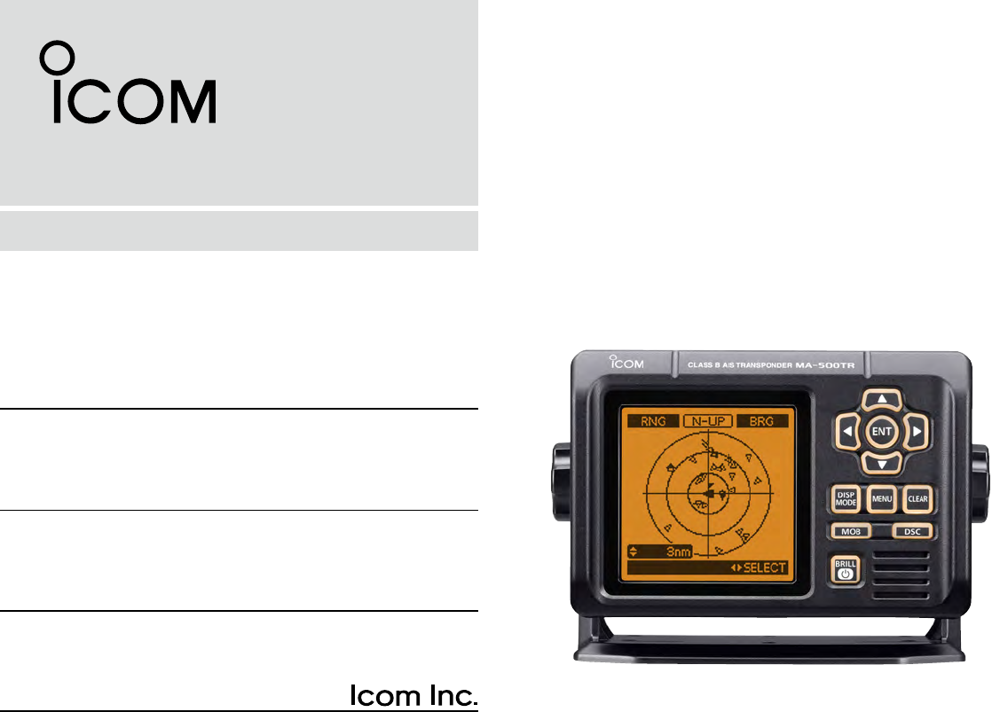
MA-500TR
CLASS B AIS TRANSPONDER
New2001
i
FOREWORD
Thank you for purchasing this Icom product.
The MA-500TR c l a s s b a i s t r a n s p o n d e r is designed and
built with Icom’s state of the art technology and craftsman-
ship. With proper care, this product should provide you with
years of trouble-free operation.
We appreciate you making the MA-500TR your transpon-
der of choice, and hope you agree with Icom’s philosophy of
“technology first.” Many hours of research and development
went into the design of your MA-500TR.
D FEATURES
❍ Full dot-matrix display visually shows real-time
vessel traffic information
❍ IPX7 waterproof protection
❍ 3 lines of NMEA0183 Input/Output
❍ GPS receiver comes with the MA-500TR
❍ Collision-risk management functions
❍ Integration with Icom VHF transceivers
*
*
See the leaflet that comes with the transponder for details of the
corresponding transceiver.
IMPORTANT
READ ALL INSTRUCTIONS carefully and completely
before using the transponder.
SAVE THIS INSTRUCTION MANUAL — This in-
struction manual contains important operating instructions
for the MA-500TR.
EXPLICIT DEFINITIONS
WORD DEFINITION
RWARNING! Personal injury, fire hazard or electric
shock may occur.
CAUTION Equipment damage may occur.
NOTE
If disregarded, inconvenience only. No risk
of personal injury, fire or electric shock.
CLEAN THE TRANSPONDER THOROUGHLY WITH
FRESH WATER after exposure to saltwater, otherwise, the
keys and switch may become inoperable due to salt crystal-
lization.
ii
New2001
FCC INFORMATION
• FOR CLASS B UNINTENTIONAL RADIATORS
This equipment has been tested and found to comply with the
limits for a Class B digital device, pursuant to part 15 of the
FCC Rules. These limits are designed to provide reasonable
protection against harmful interference in a residential instal-
lation. This equipment generates, uses and can radiate radio
frequency energy and, if not installed and used in accordance
with the instructions, may cause harmful interference to radio
communications. However, there is no guarantee that inter-
ference will not occur in a particular installation. If this equip-
ment does cause harmful interference to radio or television
reception, which can be determined by turning the equipment
off and on, the user is encouraged to try to correct the inter-
ference by one or more of the following measures:
•Reorientorrelocatethereceivingantenna.
•Increase the separation between the equipment and
receiver.
•Connecttheequipmentintoanoutletonacircuitdifferent
from that to which the receiver is connected.
•Consultthedealeroranexperiencedradio/TVtechnician
for help.
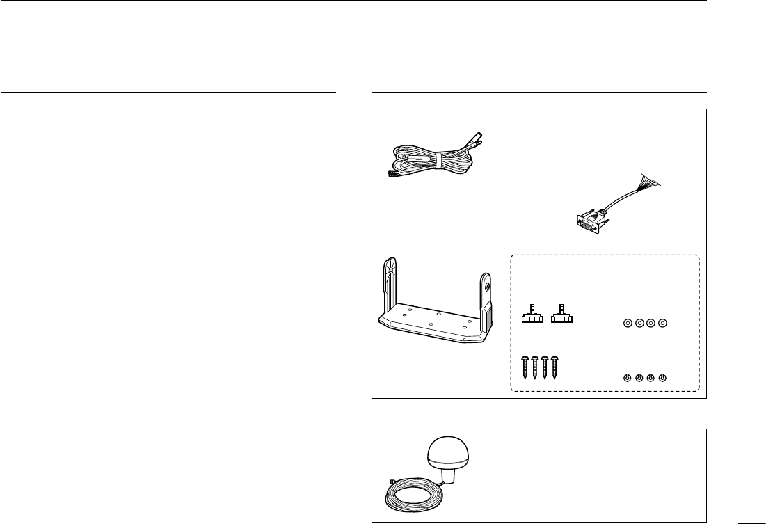
SUPPLIED ACCESSORIES
Mounting bracket
For the mounting bracket
DC power cable (OPC-2059)
Knob bolts
Screws (5×20)
Flat washers
(M5)
Spring washers
(M5)
NMEA connector cable
(OPC-2014)
MXG-5000 g p s r e c e i v e r is included with MA-500TR.
MXG-5000 (Referred to as Internal GPS)
Cable length: Approx. 10 m (32.8 ft)
•AninstructionsheetcomeswiththeMXG-
5000. Please read it before installing and
operating the MXG-5000.
•The OPC-2014 has 15
leads, numbered 1 to 15.
iii
New2001
RADIO OPERATOR WARNING
WARNING
Icom requires the radio operator to meet the
FCC Requirements for Radio Frequency Expo-
sure. An omnidirectional antenna with gain not
greater than 9 dBi must be mounted a minimum
of 5 meters (measured from the lowest point of
the antenna) vertically above the main deck and
all possible personnel. This is the minimum safe separation
distance estimated to meet all RF exposure compliance re-
quirements. This 5 meter distance is based on the FCC Safe
Maximum Permissible Exposure (MPE) distance of 3 meters
added to the height of an adult (2 meters) and is appropriate
for all vessels.
For watercraft without suitable structures, the antenna must
be mounted so as to maintain a minimum of 1 meter vertically
between the antenna, (measured from the lowest point of the
antenna), to the heads of all persons AND all persons must
stay outside of the 3 meter MPE radius.
Do not transmit with radio and antenna when persons are
within the MPE radius of the antenna, unless such persons
(such as driver or radio operator) are shielded from antenna
field by a grounded metallic barrier. The MPE Radius is the
minimum distance from the antenna axis that person should
maintain in order to avoid RF exposure higher than the allow-
able MPE level set by FCC.
FAILURE TO OBSERVE THESE LIMITS MAY ALLOW
THOSE WITHIN THE MPE RADIUS TO EXPERIENCE RF
RADIATION ABSORPTION WHICH EXCEEDS THE FCC
MAXIMUM PERMISSIBLE EXPOSURE (MPE) LIMIT.
IT IS THE RESPONSIBILITY OF THE RADIO OPERATOR
TO ENSURE THAT THE MAXIMUM PERMISSIBLE EXPO-
SURE LIMITS ARE OBSERVED AT ALL TIMES DURING
RADIO TRANSMISSION. THE RADIO OPERATOR IS TO
ENSURE THAT NO BYSTANDERS COME WITHIN THE
RADIUS OF THE MAXIMUM PERMISSIBLE EXPOSURE
LIMITS.
Determining MPE Radius
THE MAXIMUM PERMISSIBLE EXPOSURE (MPE) RADIUS
HAS BEEN ESTIMATED TO BE A RADIUS OF ABOUT 3M
PER OET BULLETIN 65 OF THE FCC.
THIS ESTIMATE IS MADE ASSUMING THE MAXIMUM
POWER OF THE RADIO AND ANTENNAS WITH A MAXI-
MUM GAIN OF 9dBi ARE USED FOR A VESSEL MOUNTED
SYSTEM.
iv
New2001
1
2
3
4
5
6
7
8
9
10
11
12
13
14
15
16
• INSTALLATION NOTES
The installation of this equipment should be made in such a
manner as to respect the EC recommended electromagnetic
eldexposurelimits(1999/519/EC).
The maximum RF power available from this device is 2 watts.
The antenna should be installed as high as possible for maxi-
mum efficiency and that this installation height should be
at least 5 meters above ground (or accessible) level. In the
case where an antenna cannot be installed at a reasonable
height, then the transmitter should neither be continuously
operated for long periods if any person is within 5 meters of
the antenna, nor operated at all if any person is touching the
antenna.
In all cases any possible risk depends on the transmitter
being activated for long periods. (actual recommendation lim-
its are specified as an average of 6 minutes) Normally the
transmitter is not active for long periods of time. Some radio
licenses will require that a timer circuit automatically cuts the
transmitter after 1 to 2 minutes etc.
Similarly some types of transmitter, SSB, CW, AM, etc. have
a lower ‘average’ output power and the perceived risk is even
lower.
ABOUT CE
CE versions of the MA-500TR which display
the “CE” symbol on the serial number label,
comply with the essential requirements of the
European Radio and Telecommunication Ter-
minalDirective1999/5/EC.
This warning symbol indicates that this equip-
ment operates in non-harmonised frequency
bandsand/ormaybesubjecttolicensingcon-
ditions in the country of use. Be sure to check
that you have the correct version of this radio
or the correct programming of this radio, to
comply with national licensing requirement.
v
New2001
ABOUT CE
DECLARATION
OF CONFORMITY
We Icom Inc. Japan
1-1-32, Kamiminami, Hirano-ku
Osaka 547-0003, Japan
Kind of equipment:
Type-designation:
Signature
Authorized representative name
Place and date of issue
Version (where applicable):
This compliance is based on conformity with the following harmonised
standards, specifications or documents:
IEC 62287-1
ITU-R M.1371-3
ITU-R M.825-3
IEC 60945 2002
EN 60950-1 2006 A11:2009
0560
Y. Furukawa
General Manager
Icom (Europe) GmbH
Communication Equipment
Auf der Krautweide 24,
65812 Bad Soden am Taunus,
Germany
CLASS B AIS TRANSPONDER
ma- 500tr
i)
ii)
iii)
iv)
v)
vi)
vii)
viii)
2nd Dec.
2010Bad Soden
Declare on our sole responsibility that this equipment complies with the
essential requirements of the Radio and Telecommunications Te rminal
Equipment Directive, 1999/5/EC, and that any applicable Essential Te st
Suite measurements have been performed.
• List of Country codes (ISO 3166-1)
Country Codes Country Codes
1
2
3
4
5
6
7
8
9
10
11
12
13
14
15
16
17
Austria
Belgium
Bulgaria
Croatia
Czech Republic
Cyprus
Denmark
Estonia
Finland
France
Germany
Greece
Hungary
Iceland
Ireland
Italy
Latvia
AT
BE
BG
HR
CZ
CY
DK
EE
FI
FR
DE
GR
HU
IS
IE
IT
LV
18
19
20
21
22
23
24
25
26
27
28
29
30
31
32
33
Liechtenstein
Lithuania
Luxembourg
Malta
Netherlands
Norway
Poland
Portugal
Romania
Slovakia
Slovenia
Spain
Sweden
Switzerland
Turkey
United Kingdom
LI
LT
LU
MT
NL
NO
PL
PT
RO
SK
SI
ES
SE
CH
TR
GB

vi
New2001
PRECAUTIONS
RWARNING! NEVER connect the transponder to an
AC outlet. This may pose a fire hazard or result in an electric
shock.
RWARNING! NEVER connect the transponder to a
powersourceofmorethan16VDCorusereversepolarity.
This could cause a fire or damage the transponder.
RWARNING! NEVER cut the DC power cable between
the DC plug at the back of the transponder and fuse holder. If
an incorrect connection is made after cutting, the transponder
may be damaged.
CAUTION:
NEVER place the
transponder
where normal
operation of the vessel may be hindered or where it could
cause bodily injury.
KEEP the transponder at least 1 m (3.3 ft) away from the
vessel’s magnetic navigation compass.
DO NOT use or place the transponder in areas with tem-
peraturesbelow–20°C(–4°F)orabove+60°C(+140°F)or,in
areas subject to direct sunlight, such as the dashboard.
DO NOT use harsh solvents such as benzine or alcohol
when cleaning, as they will damage the transponder surfaces.
If the transponder becomes dusty or dirty, wipe it clean with
a soft, dry cloth.
BE CAREFUL! The transponder rear panel will become
hot when operating continuously for long periods of time.
Place the transponder in a secure place to avoid inadvertent
use by children.
BE CAREFUL! The transponder meets IPX7* require-
ments for waterproof protection. However, once the tran-
sponder has been dropped, waterproof protection cannot be
guaranteed because of possible damage to the transponder’s
case or the waterproof seal.
* Except for the DC power and cloning cable connectors.
For U.S.A. only
CAUTION: Changes or modifications to this device, not
expressly approved by Icom Inc., could void your authority to
operate this device under FCC regulations.
Approved Icom optional equipment is designed for optimal
performance when used with an Icom transponder.
Icom is not responsible for the destruction or damage to an
Icom transponder in the event Icom transponder is used with
equipment that is not manufactured or approved by Icom.
Icom, Icom Inc. and the Icom logo are registered trademarks of Icom Incor-
porated (Japan) in Japan, the United States, the United Kingdom, Germany,
France,Spain,Russiaand/orothercountries.
MarineCommander is a trademark of Icom Incorporated.
All other products or brands are registered trademarks or trademarks of their
respective holders.

vii
New2001
TABLE OF CONTENTS
New2001
FOREWORD .........................................................................i
IMPORTANT ..........................................................................i
EXPLICIT DEFINITIONS .......................................................i
FCC INFORMATION ............................................................ ii
SUPPLIED ACCESSORIES ................................................. ii
RADIO OPERATOR WARNING .......................................... iii
ABOUT CE .......................................................................... iv
PRECAUTIONS ................................................................... vi
TABLE OF CONTENTS ...................................................... vii
1 OVERVIEW ......................................................................1
2 PANEL DESCRIPTION ................................................2–6
■ Front panel ....................................................................2
■ Function display ............................................................4
3 PREPARATION..........................................................7–13
■ MMSI code setting ........................................................7
■ Initial setting mode .......................................................9
4 BASIC OPERATION ................................................14–22
■ Turning power ON .......................................................14
■ Display backlight and contrast settings ......................15
■ Plotter display operation .............................................15
■ Target list display operation ........................................16
■ Danger list display operation ......................................17
■ About the detail screen ..............................................17
■ Individual DSC call
(Possible only when a transceiver is connected) ................22
5 OTHER FUNCTIONS ...............................................23–27
■ Message .....................................................................23
■ Waypoint .....................................................................24
■ Lost target ..................................................................27
6 MENU MODE OPERATION .....................................28–34
■ General.......................................................................28
■ Menu mode items .......................................................28
7 INSTALLATION AND CONNECTIONS ...................35–42
■ Connections ...............................................................35
■ Fuse replacement ......................................................38
■ Antenna ......................................................................38
■ Transceiver connection ...............................................39
■ Mounting the transponder ..........................................41
■ MB-75 installation .......................................................42
8 MAINTENANCE ......................................................43–45
■ Troubleshooting ..........................................................43
■ Error message ............................................................44
■ Diagnostics .................................................................44
9 SPECIFICATIONS AND OPTION ..................................46
■ Specifications .............................................................46
■ Option .........................................................................46
10 TEMPLATE ....................................................................47
11 AtoN CODE AND DESCRIPTION .................................49
1
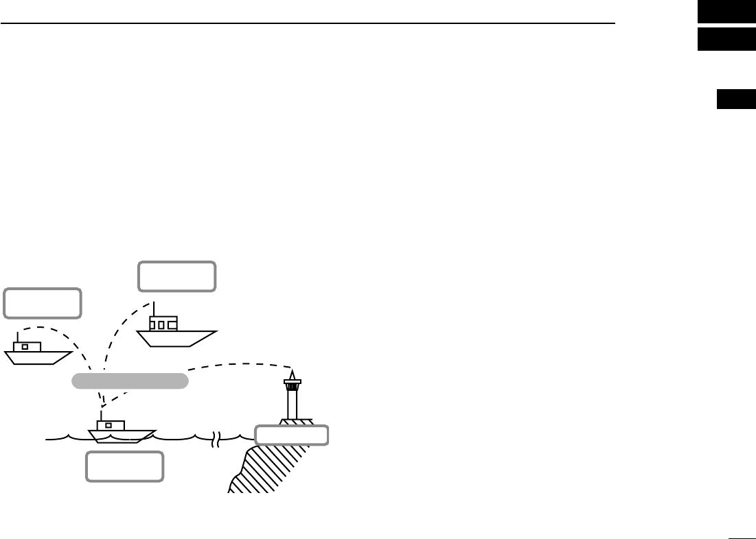
D ABOUT AIS
AIS is an acronym for “Automatic Identification System.”
An AIS transponder is a short range data radio unit, used
primarily for collision-risk management and navigation safety.
It automatically transmits and receives vessel information
such as the vessel name, MMSI code, vessel type, position
data, speed, course, destination and more. Information is ex-
changedamongthevesselsand/orbasestationsontheVHF
maritime mobile band. The information helps to identify other
nearby vessels or stations by displaying the received data on
a plotter or a radar screen.
Your vessel
(Class B AIS)
Other vessel
(Class A AIS)
Other vessel
(Class B AIS)
Base Station
Vessel information
D AIS Classes
There are four types of AIS stations; vessels, base stations,
Aids to Navigation (AtoN) and Search and Rescue (SAR).
There are two classes of AIS units, which are installed on
vessels; Class A and Class B.
Under the Safety Of Life At Sea (SOLAS) convention, all
SOLAS vessels, as described below, are required to install a
Class A AIS transponder:
•Upwards of 300 gross tonnage engaged on international
voyages.
•Passengervessels,irrespectiveofsize,engagedoninter-
national voyages.
•Upwardsof500grosstonnagenotengagedoninternational
voyages.
A Class B AIS transponder is designed to be interoperability
with Class A units, but not to impact the Class A network.
Many commercial vessels, and some leisure craft, not clas-
sified as requiring a Class A unit, choose to install a Class B
unit to avoid accidents at sea.
1
1
OVERVIEW
New2001
1
2
3
4
5
6
7
8
9
10
11
12
13
14
15
16
2
New2001
PANEL DESCRIPTION
2
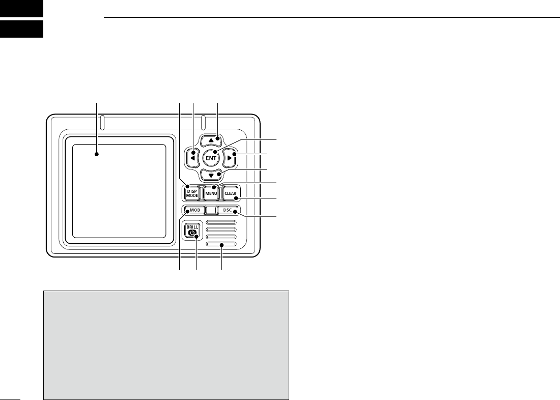
■ Front panel
Function display (p. 4)
Speaker
qw e
r
w
e
t
y
io
u
The angle brackets show common or special display op-
erations, as described below:
•<Common> shows the common operation.
•<In the plotter display> shows the plotter display opera-
tion.
•<In the target list display> shows the target list display
operation.
•<In the danger list display> shows the danger list dis-
play operation.
q DISPLAY MODE KEY [DISP MODE]
<Common>
➥ Push to switch the display mode between the plotter,
targetlistanddangerlist.(pp.4−6)
➥ While in the Menu mode, push to exit it, and return to
the plotter, target list or danger list display which was
selected before you entered the Menu mode.
w LEFT AND RIGHT KEYS [Ω]/[≈]
<Common>
While in the Menu item setting mode, push to select a
menu option. (pp. 29, 33)
<In the plotter display>
➥ Push [Ω] to sequentially select each AIS target icon far-
thest from your vessel (or waypoint, if it is set; see page
24forsettingdetail).
(p. 15)
➥ Push [≈] to sequentially select each AIS target icon
closest to your vessel (or waypoint, if it is set; see page
24forsettingdetail).
(p. 15)
•
A target box will appear around the selected target or waypoint
icon.
<In the danger list display>
➥ Push [Ω] to sort the AIS target data by CPA (Closest
Point of Approach).
(p. 17)
➥ Push [≈] to sort the AIS target data by TCPA (Time to
CPA).
(p. 17)

3
2
PANEL DESCRIPTION
New2001
e UP AND DOWN KEYS [∫]/[√]
<Common>
➥ While in the Menu mode, push to select a menu item.
(pp. 9, 28)
➥ Push to select a voice channel in the voice channel se-
lection screen.
(p. 21)
<In the plotter display>
Push to select the display range.
(p. 15)
<In the target or danger list display>
Push to select an AIS target in the target or danger list
display.
(pp. 16, 17)
r ENTER KEY [ENT]
<Common>
➥ Push to display the detail screen of the selected AIS
target.(pp.15−17)
➥ Push to save the input data. (pp. 8, 10, 15)
➥ Push to enter the Menu item setting mode.
(pp. 9, 28)
➥ While in the Menu item setting mode, push to select a
menu option.
(pp. 11, 12, 16, 29, 32
−34
)
➥ While searching for a GPS satellite, push [ENT] to dis-
playtheGPSinformationscreen.(p.14,31)
t MENU KEY [MENU]
<Common>
➥ Push to enter the Menu mode. (pp. 9, 28)
➥ While in the Menu mode, push to exit it, and return to
the plotter, target list or danger list display which was
selected before you entered the Menu mode.
y CLEAR KEY [CLEAR]
<Common>
➥ Push to cancel the entered function, or return to the pre-
vious screen. (pp. 10, 13, 23)
➥ While in the Menu mode, push to exit it, and return to the
previous screen. (pp. 9, 28)
➥Pushtostopanalarm.(pp.15−17)
u DSC KEY [DSC]
<Common>
➥ When the AIS target is selected, or the detail screen is
displayed, push to display the voice channel selection
screen. (p. 22)
➥ After selecting the voice channel, push to transmit an
Individual DSC call to the selected AIS target. (p. 22)
This function is available only when a transceiver is con-
nected to the transponder. (p. 39)
i POWER/BRILL KEY [POWER•BRILL]
<Common>
➥
Hold down for 1 second to turn the power ON or OFF.
(p.14)
•
After turning ON the power, the opening screen will appear.
➥ Push to show the display backlight and contrast adjust-
ing screen. (p. 15)
o MAN OVERBOAT KEY [MOB]
<Common>
Hold down for 1 second to set the waypoint.
(p. 25)
•TheMOBalarmsounds,andaagiconappearsonyourcurrent
position.
2
4
2PANEL DESCRIPTION
New2001
■ Function display
There are three display types; plotter, target list and danger list,
and you can select your desired type using the [DISP MODE] key.
NOTE: When one of the following messages is displayed on
the function display, push [CLEAR] to clear it.
•“PRIORITYINTERRUPTEDLASTATTEMPTS”isdisplayed
when the transponder cannot make a periodic transmission
because the transponder detects a transmit signal.
•“BASESTATIONINHIBITINGAISTXFORMM MIN”* is dis-
played when the transmission is inhibited by a base station
for the displayed time period.
*The transmission inhibit period is displayed instead of “MM.”
- “ ” is also displayed while transmission is inhibited.
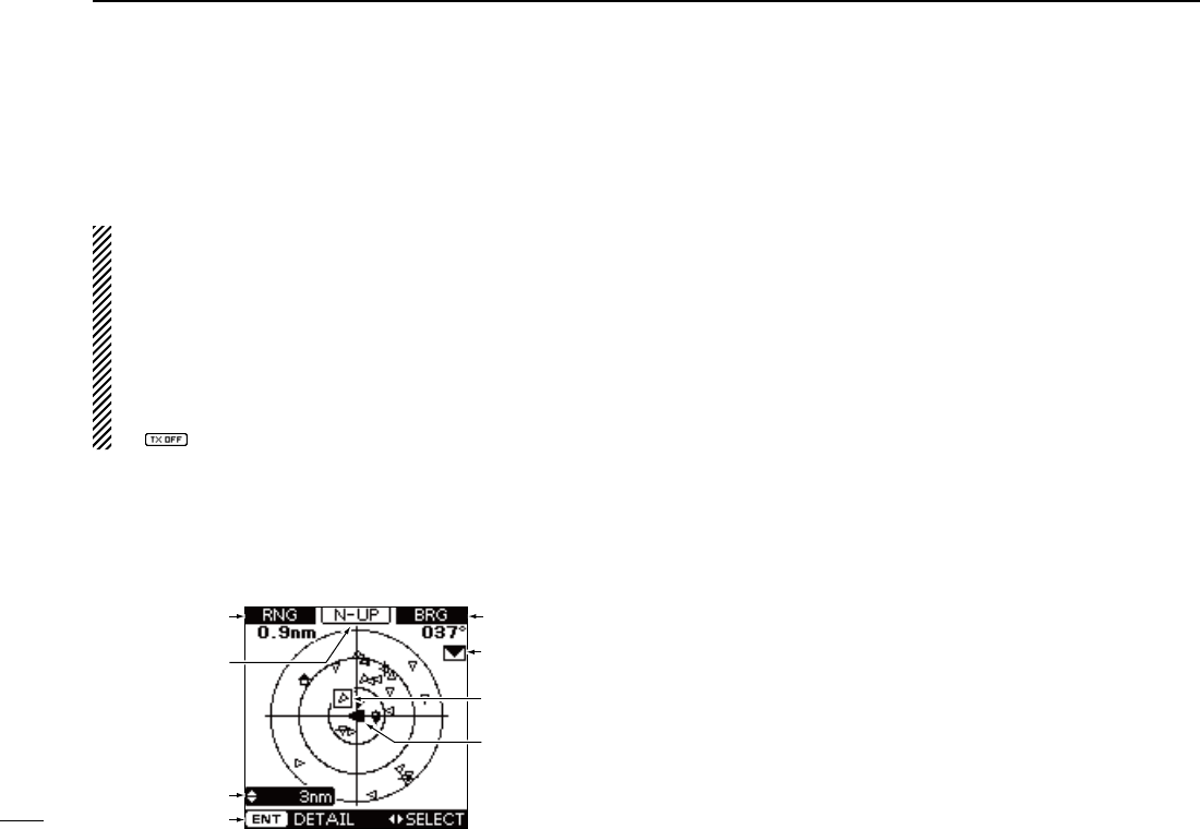
D Plotter display
After the transponder is turned ON, the plotter display automati-
cally appears, if the GPS receiver is connected and it receives
signals from a satellite. It shows the display range and the icons
of the AIS targets.
r
y
t
q
e
w
u
i
q DISPLAY TYPE
Shows the selected display type.
•When“N-UP” is displayed,thetop oftheplotterdisplayrepre-
sents North.
•When“AC-UP”isdisplayed,thetopoftheplotterdisplayrepre-
sents the direction your course is heading.
w RANGE/CPA INFORMATION
➥ Shows the range information from your vessel to the se-
lected AIS target.
➥ Shows the CPA (Closest Point of Approach) information
of the selected AIS target whose CPA is within 6 nm
(nautical miles) and TCPA (Time to CPA) is within 60
minutes of your vessel.
e BEARING/TCPA INFORMATION
➥ Shows the bearing information from your vessel to the
selected AIS target.
➥ Shows TCPA information of the selected AIS target
whose CPA is within 6 nm (nautical miles) and TCPA is
within 60 minutes of your vessel.
r MESSAGE ICON
Appears when
a message is received.
•
The message icon stays on the plotter display as long as the
unread message is stored in the RX log memory.
5
2
PANEL DESCRIPTION
New2001
1
2
3
4
5
6
7
8
9
10
11
12
13
14
15
16
t TARGET BOX
Shows the selected AIS target (or waypoint, if it is set; see
pages24–26forsettingdetail).
•When a target box appears, push [ENT] to display the detail
screen of the selected AIS target or waypoint.
y YOUR VESSEL ICON
Your
vessel icon is displayed in the center of the display.
•When“N-UP”isdisplayed,thevesseliconautomaticallypoints
inthedirectionyouareheading,in45degreessteps.
•When“AC-UP”isdisplayed,thevesseliconconstantlypointsto
the top of the plotter display.
•Whenyourvessel moves less than 2 knots, the icon is displayed
as “ .”
u KEY ENTRY GUIDE
Shows the key entry guide.
➥ Push [Ω] or [≈] to select each AIS target icon (or way-
point), in sequence.
(p. 15)
•
A target box will appear around the selected target icon.
➥ Push [ENT] to display the detail screen of the selected
AIS target or waypoint. (pp. 15–17)
i DISPLAY RANGE
Shows the selected display range.
•0.125,0.25,0.5,0.75,1.5,3,6,12,24nm(nauticalmiles)are
selectable.
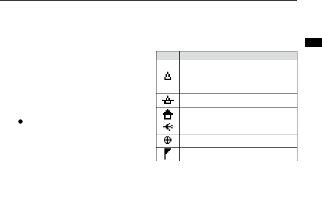
• Description of the icons
Icon Description
AIStarget:Vessel
The tip of the target triangle automatically points
in the direction it’s heading.
The icon blinks when the AIS target is closer than
your CPA and TCPA settings. (Dangerous target)
AIS target: Lost target*
The target triangle is marked with a diagonal line.
AIS target: Base Station
AIS target: Search and Rescue (SAR)
AIS target: Aids to Navigation (AtoN)
Waypoint
* A vessel is regarded as a “Lost target” after a specified pe-
riod of time has passed since the vessel last transmitted
data. (p. 27)
The “Lost target” icon disappears from the plotter display 6
minutesand 40seconds(default)after the vesselwas re-
garded as a “Lost target.” Ask your dealer for details.
6
2PANEL DESCRIPTION
New2001
■ Function display (Continued)
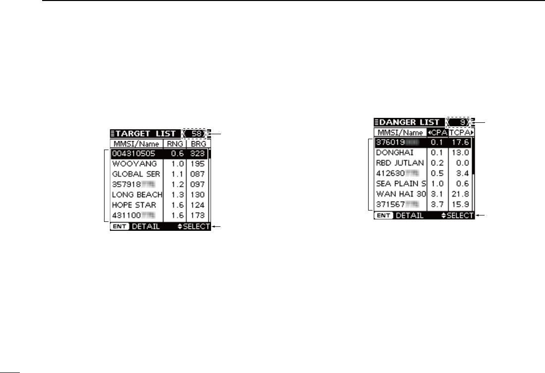
D Target list display
In the plotter display, push [DISP MODE] to switch to the tar-
get list display, which shows all AIS targets being detected by
the transponder.
The AIS target data is sorted by the distance from your ves-
sel, and the closest target is located on the top of the list.
e
q
w
q THE NUMBER OF TARGETS
Shows the number of AIS targets which are being detected
by the transponder.
w KEY ENTRY GUIDE
Shows the key entry guide.
➥ Push [∫] or [√] to select an AIS target.
(p. 16)
➥ Push [ENT] to display the detail screen of the selected
AIS target. (pp. 16, 17)
e TARGET INFORMATION
Shows the following AIS target information:
•MMSIcodeorname, if the name is programmed.
•Range(RNG)fromyourvesseltothetarget(unit:nauticalmile)
•Bearing(BRG)fromyourvesseltothetarget(unit:degree)
D Danger list display
In the target list display, push [DISP MODE] to switch to the
danger list display, which helps you to find any dangerous
target whose CPA is within 6 nm (nautical miles) and TCPA is
within 60 minutes of your vessel.
e
q
w
q THE NUMBER OF DANGEROUS TARGETS
Shows the number of AIS targets which are being detected
by the transponder.
w KEY ENTRY GUIDE
Shows the key entry guide.
➥ Push [Ω] or [≈] to sort the danger target data.
(p. 17)
➥ Push [ENT] to display the detail screen of the selected
AIS target. (p. 17)
e DANGER TARGET INFORMATION
Shows the following dangerous target information:
•MMSIcodeorname, if the name is programmed.
•CPA :ClosestPointofApproach(unit:nauticalmile)
•TCPA:TimetoCPA(unit:minute)
New2001
7
3
PREPARATION
New2001
1
2
3
4
5
6
7
8
9
10
11
12
13
14
15
16
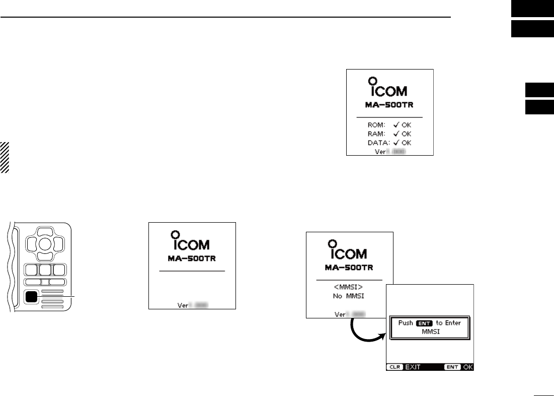
■ MMSI code setting
The 9-digit MMSI (Maritime Mobile Service Identity: DSC self
ID) code can be set at power ON. If the MMSI code has al-
ready been set, the following steps are not needed. Go to
page 9.
This initial code setting can be performed only once.
After being set, it can be changed by only your dealer or
distributor.
q Hold down [POWER•BRILL] for 1 second to turn ON the
power.
•A long beep sounds, and the opening screen appears.
[POWER•BRILL]
w The opening screen displays the results of the opening
test (ROM, RAM and backup data test); “OK” or “NG” (No
Good).
•
If “NG” is displayed, hold down [POWER•BRILL] for 1 second to turn
OFF the power, then ON again to reset the transponder. If there is no
change, contact your dealer or service center.
e After the opening test is completed, “No MMSI” appears
when no MMSI code is set.
•If the MMSI code has already been set, the MMSI code appears.
Go to page 9.
•Push[CLEAR] to skip the setting, and go to the plotter display.
In this case, the transponder operates as just an AIS receiver.
☞ Continued on the next page.
8
3PREPARATION
New2001
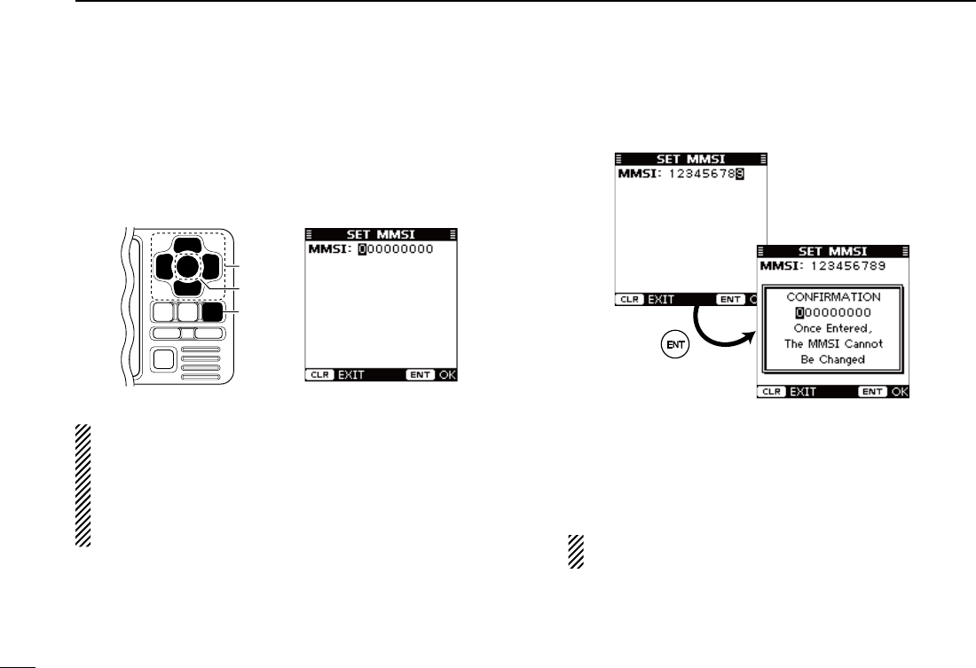
■ MMSI code setting (Continued)
r
Push [ENT] to enter the MMSI code setting mode.
t Push [∫] or [√]
to input
the specific 9-digit MMSI code.
•Push[≈] to move the cursor forward.
•Push[Ω] to move the cursor backward.
•Push[CLEAR] to cancel, and go to the plotter display. In this
case, the transponder operates as just an AIS receiver.
[CLEAR]
[ENT]
[∫], [√],
[Ω], [≈]
NOTE: The coast station ID or the group ID cannot be en-
tered as your MMSI code.
•GroupID :Therstonedigitis“0.”
•CoaststationID:Thersttwodigitsare“0.”
If you enter a code that starts with “0” or “00,” an error beep
sounds after pushing [ENT] in step y.
y After inputting the 9-digit code, push [ENT].
•TheMMSIconfirmationscreenappears.
u Input the same MMSI code which was entered in steps t
and y for the confirmation. Then, push [ENT] to save.
i After the MMSI code has been saved, the transponder au-
tomatically enters the Initial setting mode. See pages 9 to
13 for setting details.
The Initial setting mode can also be entered from the
Menu mode. (p. 9)
9
3
PREPARATION
New2001
1
2
3
4
5
6
7
8
9
10
11
12
13
14
15
16
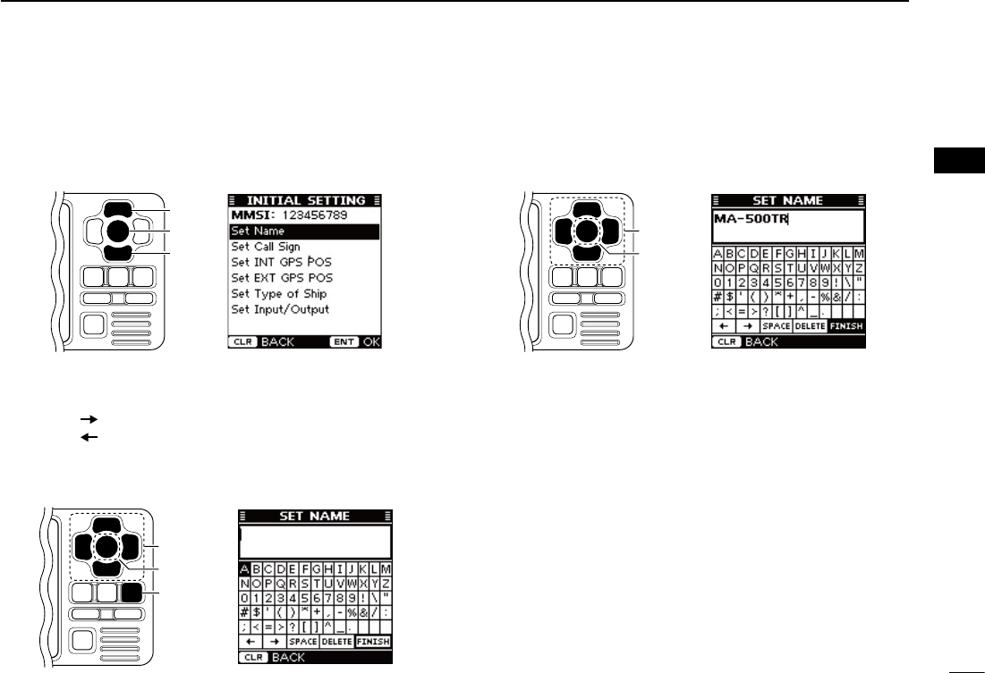
■ Initial setting mode
The Initial setting mode allows you to set the vessel’s infor-
mation that is exchanged among the vessels and/or base
stations.And,youcansettheseldom-changedNMEAInput/
Output settings.
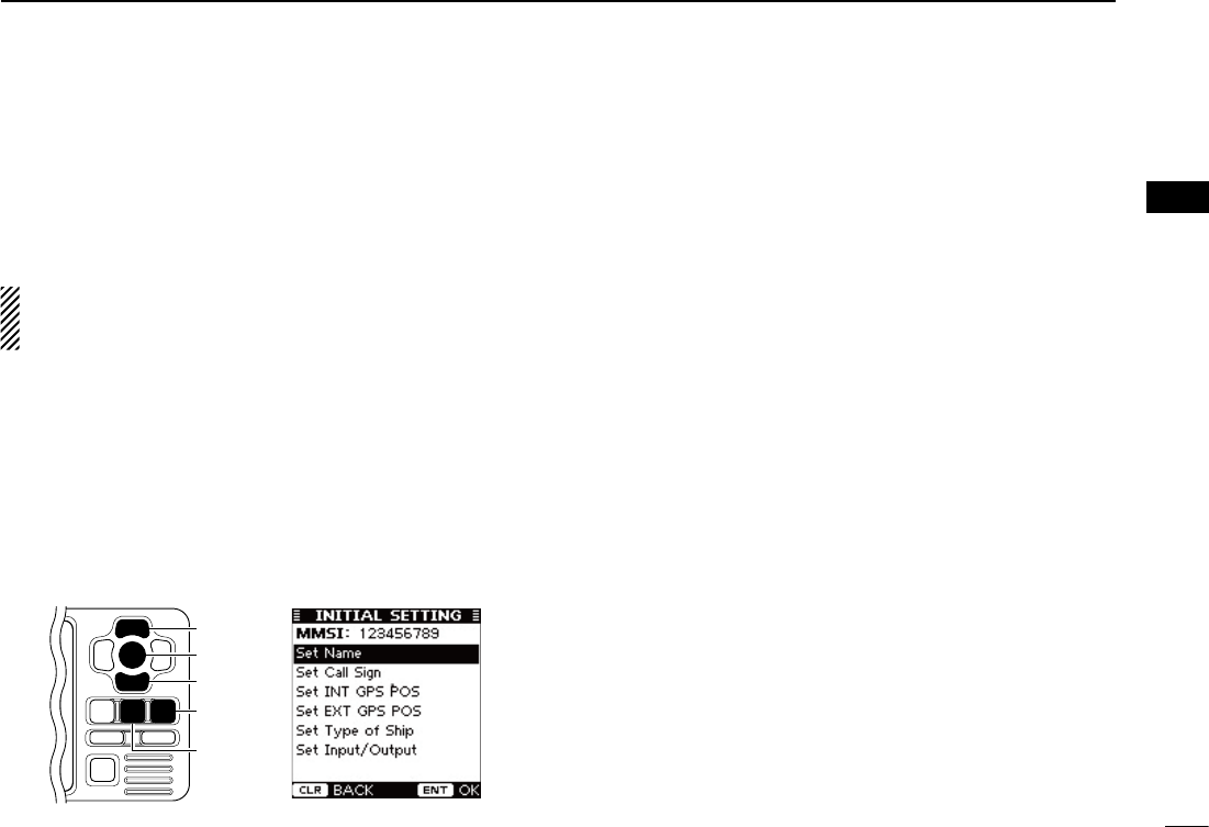
NOTE: After the MMSI code programming, the transpon-
der automatically enters the Initial setting mode. In this
case, skip steps q and w.
q Push [MENU] to enter the Menu mode.
w Push [∫] or [√] to select “Initial Setting,” then push [ENT].
e
Push [∫] or [√] to select the desired item, then push [ENT].
r Enter the characters or select the desired option.
The procedures are described on pages 10 to 13.
t Repeat steps e and r to set other items.
y Push [CLEAR] to exit the Initial setting mode, and return
to the Menu mode.
u Push [CLEAR] to exit the Menu mode.
[CLEAR]
[ENT]
[MENU]
[∫]
[√]
D MMSI code
Enter the vessel’s MMSI code.
See page 7 for setting details.
•IftheMMSIcodehasalreadybeenset,youcannotchangethis.
D Name
Enter the vessel’s name of up to 20 characters.
See page 13 for setting details.
D Call Sign
Enter the Call Sign of up to 7 characters.
The Call Sign is a unique designation ID for a station.
See page 13 for setting details.
10
3PREPARATION
New2001
■ Initial setting mode (Continued)
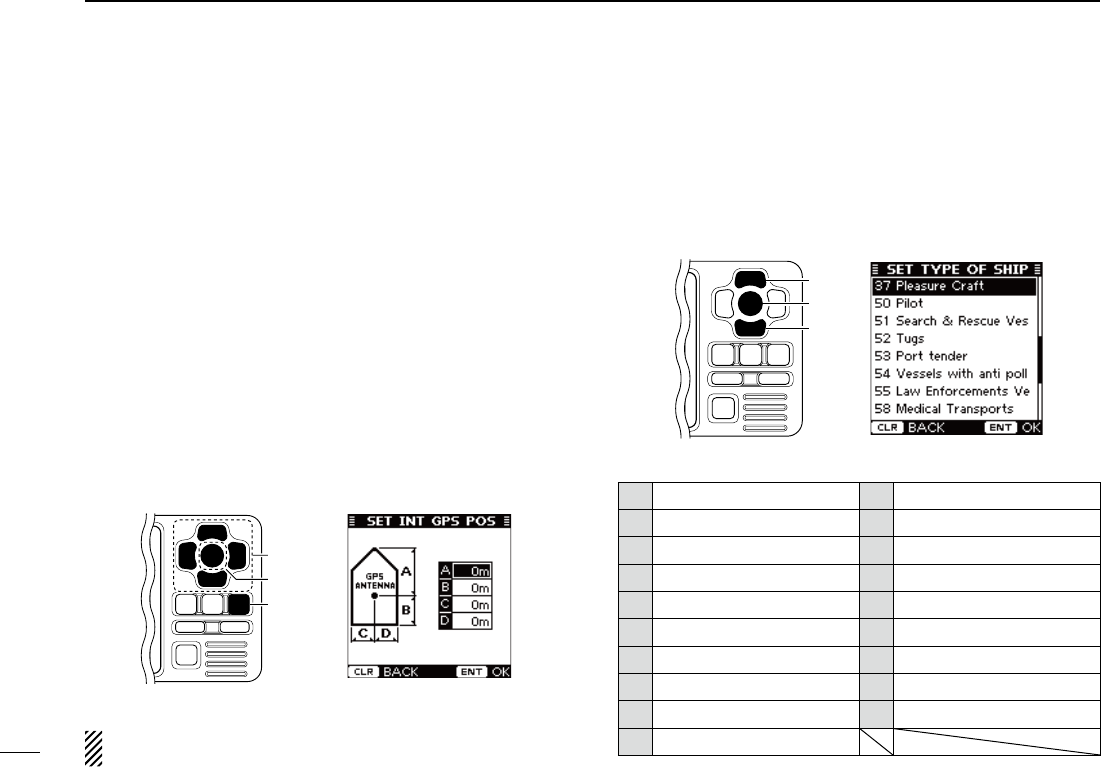
D Internal/External GPS Antenna Position
Setthesemeasurementstoindicatetheinternaland/orexter-
nal GPS antenna position on the vessel.
•InternalGPSantenna :The GPS antenna which is connected to
the [GPS] connector.
•ExternalGPSantenna:
The GPS antenna which is connected to one
of the NMEA lines. (p. 37)
q Push [∫] or [√] to select “A,” “B,” “C” or “D.”
•A : Bow to Antenna
•B : Stern to Antenna
•C : Port side to Antenna
•D : Starboard side to Antenna
•Push[CLEAR] to cancel and return to the previous screen.
w Push [Ω] or [≈] to input the value into that item.
A and B : Between 0 and 511 meters (0 and 1676.5 feet)
C and D : Between 0 and 63 meters (0 and 206.6 feet)
e Repeat steps q and w to input other values.
r Push [ENT] to save and return to the Initial setting mode.
[CLEAR]
[ENT]
[∫], [√],
[Ω], [≈]
To show the external GPS antenna set screen, select
“Set
EXT GPS POS” in the “Initial Setting” mode. (p. 9)
D Type of Ship
Select your vessel type.
➥ P ush
[∫] or [√]
to select your vessel type from the list,
then push [ENT] to save and return to the Initial setting
mode.
[ENT]
[∫]
[√]
• Type of Ship List
30 Fishing 52 Tugs
31 Towing 53 Port tender
32 Towing & two < 200m 54 Vesselswithantipollution
33 Engaged in Dredging 55 LawenforcementsVessel
34 Engaged in Diving 58 Medical Transports
35 Engaged in Military 59 Ships RR Resolution NO18
36 Sailing 60 Passenger Ship
37 Pleasure Craft 70 Cargo Ship
50 Pilot 80 Tanker
51 Search&RescueVessel
This screen shows the inter-
nal GPS antenna set screen.
11
3
PREPARATION
New2001
1
2
3
4
5
6
7
8
9
10
11
12
13
14
15
16
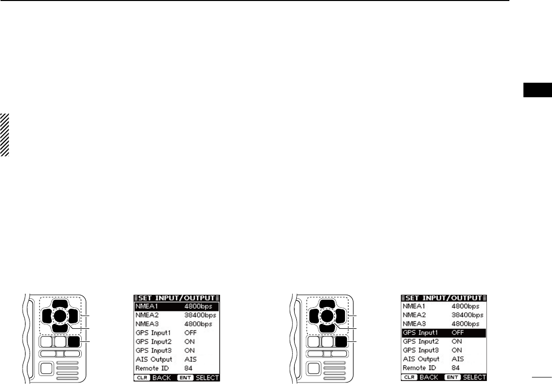
D NMEA Input/Output ports
• NMEA1/NMEA2/NMEA3 data speed
The data communication speed (baud rate) can be set for
eachInput/Outputport;NMEA1andNMEA3.
NOTE: The data communication speed of NMEA2 is fixed
to38400bps.NMEA2isused for communication between
the transponder and the Icom MarineCommander™ sys-
tem or a GPS receiver.
q P
ush [∫] or [√] to select “NMEA1” or “NMEA3.”
•NMEA1 : Used for communication between the transponder and
atransceiveroraGPSreceiver.(Default:4800bps)
•NMEA3 : Used for communication between the transponder and
a navigational equipment or a GPS receiver.
(Default:4800bps)
•Youcannotselect“NMEA2.”
w Push [ENT] to select the data communication speed be-
tween4800bpsand38400bpsintothatitem.
•Youcanalsoselecttheoptionbypushing[Ω] or [≈].
e Repeat steps q and w to set another port.
r
Push [CLEAR] to save and return to the Initial setting mode.
[CLEAR]
[ENT]
[∫], [√],
[Ω], [≈]
• GPS Input1/GPS Input2/GPS Input3
Set the NMEA1, NMEA2 and NMEA3 Input ports’ capability.
q P
ush [∫] or [√] to select “GPS Input1,” “GPS Input2” or
“GPS Input3.”
•
“GPS Input1” is for the NMEA1, “GPS Input2” is for the NMEA2
and “GPS Input3” is for the NMEA3 ports setting.
w Push [ENT] to toggle this function ON or OFF.
•You can also turn thefunction ON bypushing [≈], or OFF by
pushing [Ω].
ON : The GPS information that is received from the ex-
ternal GPS receiver of the selected port is sent to
the transponder.
(Default for
“GPS Input2” and “GPS Input3”
)
OFF : The GPS information that is received from the ex-
ternal GPS receiver of the selected port is not sent
to the transponder. (Default for
“GPS Input1”
)
e Repeat steps q and w to set other ports’ capability.
r Push [CLEAR] to save and return to the Initial setting
mode.
[CLEAR]
[ENT]
[∫], [√],
[Ω], [≈]
12
3PREPARATION
New2001
■ Initial setting mode
DNMEAInput/Outputports(Continued)
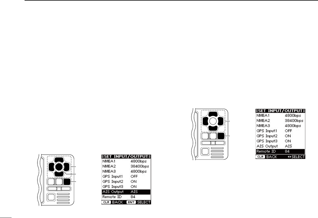
• AIS Output
Set the NMEA2 Output port’s capability.
This function should normally be set to “
AIS
.”
q P
ush [∫] or [√] to select “AIS Output.”
w Push [ENT]toselecteither“AIS”or“AIS+GPS.”
•Youcanalsoselecttheoptionbypushing[Ω] or [≈].
AIS : The NMEA2 Output port sends only the AIS
information to the connected device. (Default)
AIS+GPS :The NMEA2 Output port sends both the AIS
and GPS information to the connected device.
This setting is recommended for use in an
area where there are few vessels. In an area
crowded with AIS equipped vessels, some AIS
information may be missed.
e Push [CLEAR] to save and return to the Initial setting
mode.
[CLEAR]
[ENT]
[∫], [√],
[Ω], [≈]
• Remote ID
Set a Remote ID number between 80 and 89.
The Remote ID is included in the sentence of the format for
the Icom own NMEA.
q P
ush [∫] or [√] to select “Remote ID
.
”
w Push [Ω] or [≈] to set a Remote ID number between 80
and 89.
e Push [CLEAR] to save and return to the Initial setting
mode.
[CLEAR]
[∫], [√],
[Ω], [≈]
13
3
PREPARATION
New2001
1
2
3
4
5
6
7
8
9
10
11
12
13
14
15
16
D
Name and Call Sign settings
q P
ush [∫] or [√] to select the “Set Name” or “Set Call Sign”
that you want to program, then push [ENT] to
enter the set-
ting mode.
[ENT]
[∫]
[√]
w Push [∫], [√], [Ω] or [≈] to select the desired character in
the table, then push [ENT] to input it.
•Select“ ,” then push [ENT] to move the cursor forward.
•Select“ ,” then push [ENT] to move the cursor backward.
•Select“SPACE,” then push [ENT] to input a space.
•Select“DELETE,” then push [ENT] to delete a character.
•Push[CLEAR] to cancel and return to the previous screen.
[CLEAR]
[ENT]
[∫], [√],
[Ω], [≈]
e Repeat step w to input all characters.
r Push [∫], [√], [Ω] or [≈] to select “FINISH,” then push
[ENT] to save and return to the Initial setting mode.
[ENT]
[∫], [√],
[Ω], [≈]
New2001
14
New2001
BASIC OPERATION
4
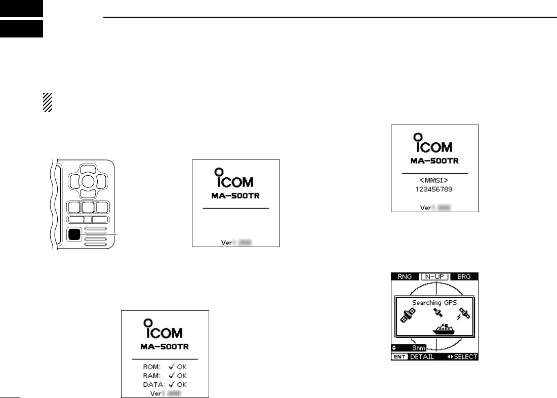
■ Turning power ON
IMPORTANT: BE SURE to connect the GPS receiver to
the transponder before turning the power ON. (p. 35)
q Hold down [POWER•BRILL] for 1 second to turn ON the
power.
•A long beep sounds, and the opening screen appears.
[POWER•BRILL]
w The opening screen displays the results of the ROM, RAM
and backup data test, “OK” or “NG” (No Good).
•
If “NG” is displayed, hold down [POWER•BRILL] for 1 second to turn
OFF the power, then ON again to reset the transponder. If there is no
change, contact your dealer or service center.
e After the opening test is completed, the MMSI code ap-
pears, if the code has already been set.
•“NoMMSI”appearswhennoMMSIcodeisset. (p. 7)
r The GPS search display appears while searching for a
GPS satellite.
•Whilesearching,theGPSinformationscreencanbedisplayed
by pushing [ENT], or you can enter the Menu mode by pushing
[MENU]. (pp. 28, 31)
t When the GPS receiver receives signals from a satellite,
the transponder automatically displays the position data
on the plotter display. (p. 15)

New2001
15
4
BASIC OPERATION
New2001
1
2
3
4
5
6
7
8
9
10
11
12
13
14
15
16
■ Display backlight and
contrast settings
You can adjust the display backlight and contrast settings.
The display backlight lights the function display and keys, and
is convenient for nighttime operation.
Also, you can adjust the display contrast between objects and
the background.
qPush [POWER•BRILL] to display the popup screen to ad-
just the display backlight and contrast level.
w Push [∫] or [√] to select “Backlight” or “Contrast,” which-
ever one you want to adjust.
e Push [Ω] or [≈] to adjust the level.
•Backlight:Between1and7,orOFF
•Contrast :Between1and8
r Push [ENT] to save the settings and turn OFF the popup
screen.
•Ifnokeyoperationisperformedfor5seconds,the backlight and
contrast levels are saved, and the popup screen automatically
turns OFF.
Convenient!
Each push of [POWER•BRILL] after the popup screen is dis-
played, also adjusts the display backlight level.
■ Plotter display operation
When the plotter display is selected, the display range and the
icons of the AIS targets appear. You can change the display range
and type (North up or COG up) to suit your operating style.
qPush [DISP MODE] several times to select the plotter dis-
play.
w Push [∫] or [√] to select the desired display range.
•0.125,0.25,0.5,0.75,1.5,3,6,12,24nm(nauticalmiles)are
selectable.
e Push [≈] to sequentially select each AIS target icon clos-
est to your vessel (orwaypoint,ifitisset;seepage24for
setting detail), in sequence.
Or, push [Ω] to select each AIS target (or waypoint) icon
farthest from your vessel, in sequence.
•Atargetboxwillappeararoundtheselectedtarget(orwaypoint)
icon.
• Shows the range and bearing information from your vessel to the
selected AIS target.
• Shows the CPA (Closest Point of Approach) and TCPA (Time to
CPA) information of the selected AIS target whose CPA is less
than 6 nm (nautical miles) and TCPA is less than 60 minutes to
your vessel.
r Push [ENT] to display it’s detail screen. (p. 17)
NOTE: The alarm buzzer sounds when a malfunction oc-
curs or an AIS target is closer than your CPA and TCPA
settings,dependingonthepresetting.(pp.29,30,33,44)
➥ To stop the alarm buzzer, push [CLEAR].
•
If the popup screen is displayed, push [CLEAR] again to turn it OFF.
16
4BASIC OPERATION
New2001
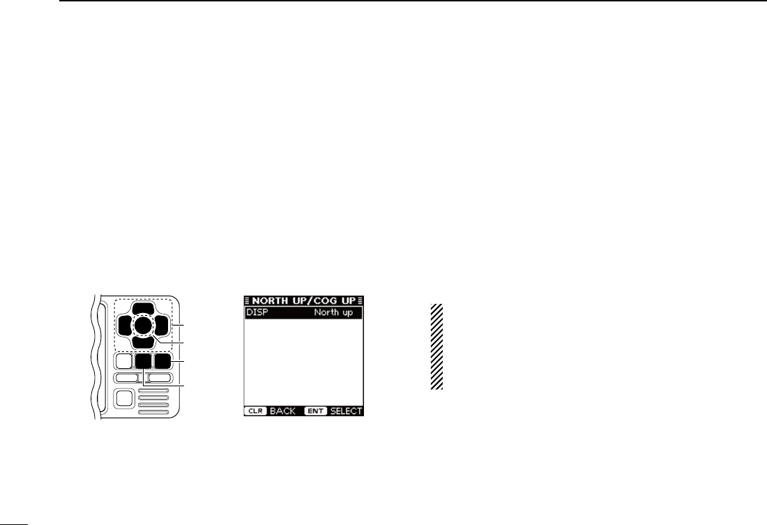
■ Plotter display operation (Continued)
D Setting the display type (North up/COG up)
Select the display type between “North up” and “COG up.”
q Push [MENU] to enter the Menu mode.
w Push [∫] or [√]toselect“Northup/COGup,”thenpush
[ENT].
e Push [ENT] to select either “North up” or “COG up.”
•Youcanalsoselecttheoptionbypushing[Ω] or [≈].
North up : The top of the plotter display represents North.
COG up : The top of the plotter display represents the di-
rection your course is heading.
r Push [CLEAR] to save and return to the Menu mode.
t Push [CLEAR] to exit the Menu mode.
[CLEAR]
[ENT]
[MENU]
[∫], [√],
[Ω], [≈]
■ Target list display operation
The target list display shows all AIS targets being detected
by the transponder, including their range and bearing infor-
mation.
The AIS target data is sorted by the distance from your ves-
sel, and the closest target is located on the top of the list.
Their range and bearing information is automatically updated
every 5 seconds, then the AIS target data is sorted.
qPush [DISP MODE] several times to select the target list
display.
w Push [∫] or [√] to select the desired AIS target.
e Push [ENT] to display it’s detail screen. (p. 17)
NOTE: The alarm buzzer sounds when a malfunction oc-
curs or an AIS target is closer than your CPA and TCPA
settings,dependingonthepresetting.(pp.29,30,33,44)
➥ To stop the alarm buzzer, push [CLEAR].
•Ifthepopupscreenisdisplayed,push[CLEAR] again to turn
it OFF.

17
4
BASIC OPERATION
New2001
1
2
3
4
5
6
7
8
9
10
11
12
13
14
15
16
■ Danger list display operation
The danger list display shows any dangerous target whose
CPA (Closest Point of Approach) distance is less than 6 nm
(nautical miles), and TCPA (Time to CPA) time is less than 60
minutes to your vessel.
The dangerous target data is sorted by CPA or TCPA (you
can choose either; see step q).
Their CPA and TCPA information is automatically updated
every 5 seconds, then the dangerous target data is sorted.
qPush [DISP MODE] several times to select the danger list
display.
•Push [Ω] to sort the AIS target data by CPA.
•Push [≈] to sort the AIS target data by TCPA.
w Push [∫] or [√] to select the desired AIS target.
e Push [ENT] to display it’s detail screen. (See to the right)
NOTE: The alarm buzzer sounds when a malfunction oc-
curs or an AIS target is closer than your CPA and TCPA
settings,dependingonthepresetting.(pp.29,30,33,44)
➥ To stop the alarm buzzer, push [CLEAR].
•Ifthepopupscreenisdisplayed,push[CLEAR] again to turn
it OFF.
■ About the detail screen
The detail screen shows information about the selected AIS
target. The contents differ, depending on the AIS class.
In the detail screen, pushing [CLEAR] returns to the previ-
ous screen, which was displayed before entering the details
screen.
See pages 18 to 21 for the detail screen of each AIS class.
18
4BASIC OPERATION
New2001
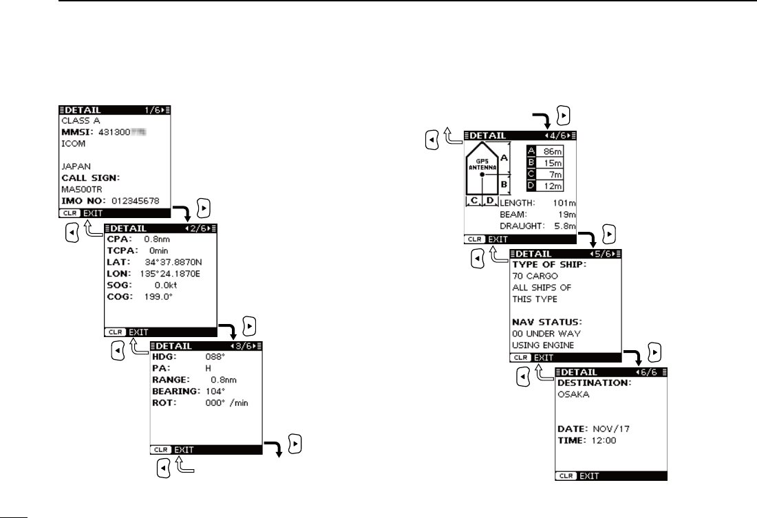
■ About the detail screen (Continued)
D The detail screens of “Class A” vessels
Detail screen 4/6
Detail screen 3/6
•AISClass
•MMSICode
•ShipName
•CountryName
•CallSign
•IMONumber
•CPA
•TCPA
•Latitude
•Longitude
•SpeedOverGround
•CourseOverGround
•Heading
•PositionAccuracy
(H: High, L: Low)
•Range
•Bearing
•RateOfTurn
•A:BowtoAntenna
•B:SterntoAntenna
•C:PortsidetoAntenna
•D:StarboardsidetoAntenna
•Length
•Beam
•Draught
•TypeofShip
•NavigationStatus
•Destination
•Date
•Time
19
4
BASIC OPERATION
New2001
1
2
3
4
5
6
7
8
9
10
11
12
13
14
15
16
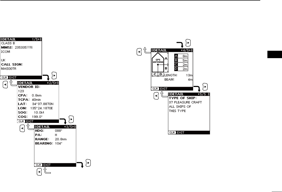
D The detail screens of “Class B” vessels
Detail screen 4/5
Detail screen 3/5
•AISClass
•MMSICode
•ShipName
•CountryName
•CallSign
•VendorID
•CPA
•TCPA
•Latitude
•Longitude
•SpeedOverGround
•CourseOverGround
•Heading
•PositionAccuracy
(H: High, L: Low)
•Range
•Bearing
•A:BowtoAntenna
•B:SterntoAntenna
•C:PortsidetoAntenna
•D:StarboardsidetoAntenna
•Length
•Beam
•TypeofShip
20
4BASIC OPERATION
New2001
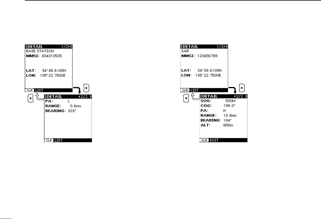
■ About the detail screen (Continued)
D
The
detail screens
of a “Base Station”
D The detail screens of an “SAR”
•AISClass
•MMSICode
•Latitude
•Longitude
•PositionAccuracy
(H: High, L: Low)
•Range
•Bearing
•AISClass
•MMSICode
•Latitude
•Longitude
•SpeedOverGround
•CourseOverGround
•PositionAccuracy
(H: High, L: Low)
•Range
•Bearing
•Altitude
21
4
BASIC OPERATION
New2001
1
2
3
4
5
6
7
8
9
10
11
12
13
14
15
16
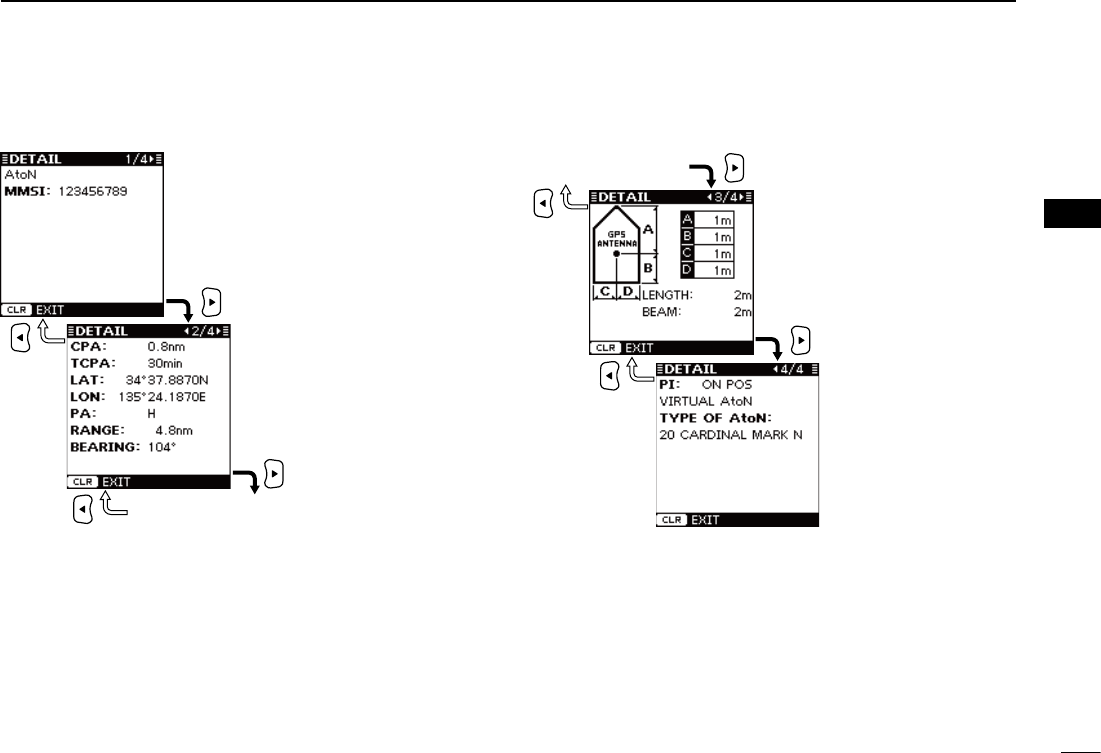
D The detail screens of an “AtoN”
Detail screen 3/4
Detail screen 2/4
•AISClass
•MMSICode
•CPA
•TCPA
•Latitude
•Longitude
•PositionAccuracy
(H: High, L: Low)
•Range
•Bearing
•A:BowtoAntenna
•B:SterntoAntenna
•C:PortsidetoAntenna
•D:StarboardsidetoAntenna
•Length
•Beam
•PositionIndicator
( ON POS : ON Position,
OFF POS :
OFF Position
)
•AtoNexistence
(REAL,VIRTUAL)
•TypeofAtoN
(Seepage49)
•DescriptionofAtoN
New2001
22
4BASIC OPERATION
New2001
When a transceiver* is connected to the transponder, you can
transmit an Individual DSC call without needing to enter the
vessel’s MMSI code, by simply selecting it’s AIS target and
the voice channel you wish to use on the transponder.
The transceiver will use the transponder’s data information
and make the DSC call on channel 70, then wait for the target
vessel to acknowledge it. After receiving the acknowledge-
ment ‘Able to comply,’ use the transceiver to communicate with
the target vessel on the predetermined voice channel.
*
See the leaflet that comes with the transponder
for details of the trans-
ceivers which can operate with this function.
Seepages39and40forconnectinginstructions.
NOTE: The data communication speed (baud rate) of
NMEA1 must be set to 4800 bps to send an Individual
DSC call using the transponder. (p. 11)
q Select the desired AIS target on the plotter, target list or
danger list display. (pp. 15–17)
•Youcanalsogotothenextstepwheneverthedetailscreenof
the AIS target is displayed.
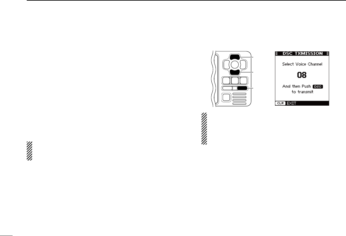
w Push [DSC] to display the voice channel selection screen,
then push [∫] or [√] to select the desired voice channel.
•Voicechannelsarealreadypresetintothetransponderinrecom-
mended order.
[DSC]
[∫]
[√]
NOTE: When a base station is selected in step q, a
voice channel will be specified by the base station,
therefore you cannot change the channel. The tran-
sponderwilldisplay“VoiceChannelisspeciedbythe
Base station,” in this case.
e Push [DSC] to make the Individual DSC call.
•
“DSC Transmitting” appears.
•IfChannel70isbusy,thetransceiverstandsbyuntilthechannel
becomes clear.
•
If the transceiver cannot make the call, “DSC Transmission FAILED”
appears.
r After making the Individual DSC call, “DSC Transmission
COMPLETED” appears.
t Push [CLEAR] to return to the previous screen before you
entered the voice channel selection screen in step w.
y After receiving the acknowledgement from the AIS target,
use the transceiver to communicate. See the transceiver’s
manual for details.
■ Individual DSC call (Possible only when a transceiver is connected)
23
5
OTHER FUNCTIONS
New2001
1
2
3
4
5
6
7
8
9
10
11
12
13
14
15
16
■ Message
D Receiving a message
A safety-related message of up to 161 characters can be re-
ceived from an AIS equipped vessel in the area.
When a message is received, a beep sounds three times,
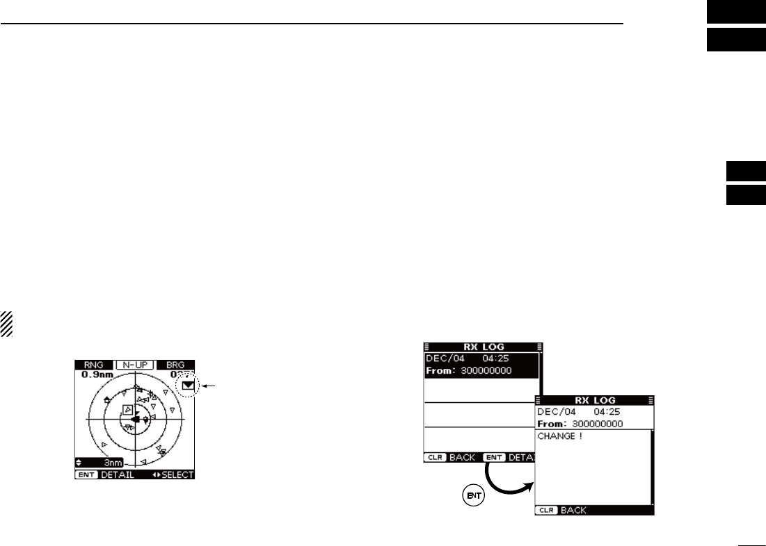
and the message icon appears on the plotter display. (The
message icon does not appear on the target list or danger
list display.)
The contents of the message can be checked in the receive
message log, as described to the right.
The message icon stays on the plotter display as long as the
unread message is stored in the RX log memory.
NOTE: The transponder automatically stores the received
messages in the RX log memory. (See to the right)
Appears
Plotter display
D Message logs
The transponder automatically stores the last 20 received
messages in the log memory.
The oldest message is automatically deleted when a new
message is received.
q Push [MENU] to enter the Menu mode.
w Push [∫] or [√] to select “Message,” then push [ENT].
e Push [∫] or [√] to select “RX Log,” then push [ENT].
r Push [∫] or [√] to select the message that you want to
read, then push [ENT].
•Thecontentsoftheselectedmessagearedisplayed.
t
Push [CLEAR] to return to the previous screen.
y Push [CLEAR] three times to exit the Menu mode.
24
5OTHER FUNCTIONS
New2001 New2001
■ Waypoint
D Display a waypoint list
Up to 100 waypoints can be stored in the waypoint list.
q Push [MENU] to enter the Menu mode.
w Push [∫] or [√] to select “Waypoint,” then push [ENT].
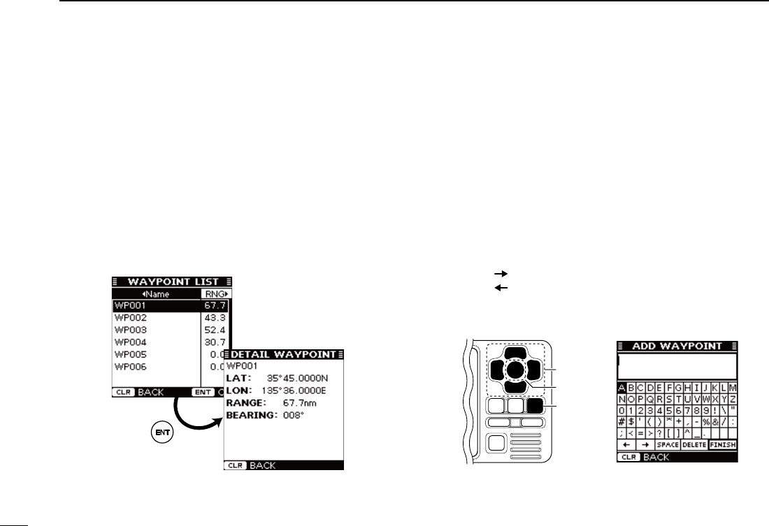
e Push [∫] or [√] to select “List,” then push [ENT].
r Push [∫] or [√] to select the desired waypoint.
•Push [Ω] to sort the waypoint data by Name.
•Push [≈] to sort the waypoint data by Range.
t Push [ENT] to display the detail screen of the selected
waypoint.
y Push [CLEAR] to return to the previous screen.
u Push [CLEAR] three times to exit the Menu mode.
D Add a waypoint
The position information that you want to memorize can be
added as a waypoint.
q Push [MENU] to enter the Menu mode.
w Push [∫] or [√] to select “Waypoint,” then push [ENT].
e Push [∫] or [√] to select “Add,” then push [ENT].
•Yourcurrentpositioninformationisdisplayed.
r Push [∫] or [√] to select “Name,” then push [ENT].
t Push [∫], [√], [Ω] or [≈] to select the desired character in
the table, then push [ENT] to input it.
•Select“ ,” then push [ENT] to move the cursor forward.
•Select“ ,” then push [ENT] to move the cursor backward.
•Select“SPACE,” then push [ENT] to input a space.
•Select“DELETE,” then push [ENT] to delete a character.
•Push[CLEAR] to cancel and return to the previous screen.
[CLEAR]
[ENT]
[∫], [√],
[Ω], [≈]
y Repeat step t to input a waypoint name of up to 10 char-
acters.
u Push [∫], [√], [Ω] or [≈] to select “FINISH,” then push
[ENT] to set and return to the previous screen.
New2001
25
5
OTHER FUNCTIONS
New2001
1
2
3
4
5
6
7
8
9
10
11
12
13
14
15
16
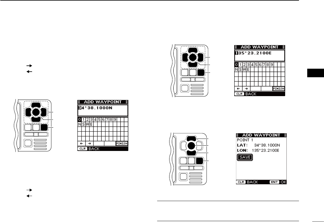
i Push [∫] or [√] to select “LAT:,” then push [ENT].
o Push [∫], [√], [Ω] or [≈] to set the desired latitude data in
the table, then push [ENT] to input it.
•Select“ ,” then push [ENT] to move the cursor forward.
•Select“ ,” then push [ENT] to move the cursor backward.
•Select“N,” then push [ENT] to input N; North latitude.
•Select“S,” then push [ENT] to input S; South latitude.
•“W” and “E” cannot be input.
•Push[CLEAR] to cancel and return to the previous screen.
[CLEAR]
[ENT]
[∫], [√],
[Ω], [≈]
!0 Push [∫], [√], [Ω] or [≈] to select “FINISH,” then push
[ENT] to set and return to the previous screen.
!1 Push [∫] or [√] to select “LON:,” then push [ENT].
!2 Push [∫], [√], [Ω] or [≈] to set the desired longitude data
in the table, then push [ENT] to input it.
•Select“ ,” then push [ENT] to move the cursor forward.
•Select“ ,” then push [ENT] to move the cursor backward.
•Select“W,” then push [ENT] to input W; West longitude.
•Select“E,” then push [ENT] to input E; East longitude.
•“N” and “S” cannot be input.
•Push[CLEAR] to cancel and return to the previous screen.
[CLEAR]
[ENT]
[∫], [√],
[Ω], [≈]
!3 Push [∫], [√], [Ω] or [≈] to select “FINISH,” then push
[ENT] to set and return to the previous screen.
!4 Push [∫] or [√]toselect“SAVE,”thenpush[ENT] to save
the waypoint data
and return to
the “WAYPOINT”
screen.
•Push[CLEAR] to cancel and return to the previous screen.
[CLEAR]
[ENT]
[∫]
[√]
!5 Push [CLEAR] twice to exit the Menu mode.
Convenient!
Each time you hold down of [MOB] also adds a waypoint. See
page 26 to edit the waypoint data.
26
5OTHER FUNCTIONS
New2001
■ Waypoint (Continued)
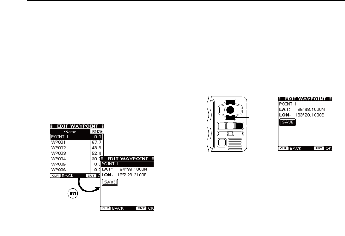
D Edit a waypoint
A waypoint’s name, latitude and longitude data can be ed-
ited.
q Push [MENU] to enter the Menu mode.
w Push [∫] or [√] to select “Waypoint,” then push [ENT].
e Push [∫] or [√] to select “Edit,” then push [ENT].
•The “EDIT WAYPOINT” list is displayed.
r Push [∫] or [√] to select the desired waypoint.
•Push [Ω] to sort the waypoint data by Name.
•Push [≈] to sort the waypoint data by Range.
t Push [ENT] to enter the edit item selection screen.
y Push [∫] or [√] to select the top item (waypoint name),
then push [ENT].
u Enter a waypoint name, latitude data and longitude data,
as described in steps t to !3 of “D Add a Waypoint” on
pages24and25.
i Push [∫] or [√]toselect“SAVE,”thenpush[ENT] to save
the edited data
and return to
the “EDIT WAYPOINT”
list
screen.
•Push[CLEAR] to cancel and return to the previous screen.
[CLEAR]
[ENT]
[∫]
[√]
o Push [CLEAR] three times to exit the Menu mode.
27
5
OTHER FUNCTIONS
New2001
1
2
3
4
5
6
7
8
9
10
11
12
13
14
15
16
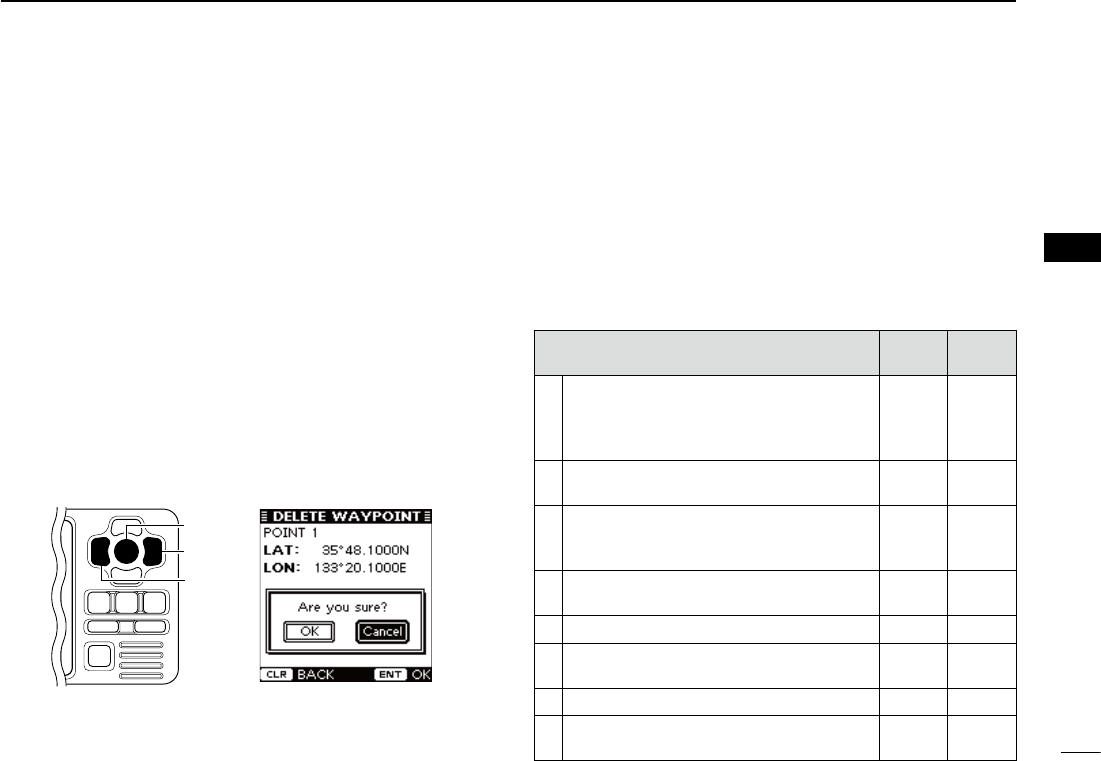
D Delete a waypoint
A waypoint can be deleted from the waypoint list.
q Push [MENU] to enter the Menu mode.
w Push [∫] or [√] to select “Waypoint,” then push [ENT].
e Push [∫] or [√] to select “Delete,” then push [ENT].
•The “DELETE WAYPOINT” list is displayed.
r Push [∫] or [√] to select the desired waypoint.
•Push [Ω] to sort the waypoint data by Name.
•Push [≈] to sort the waypoint data by Range.
t
Push [ENT] to display the detail screen of the selected way-
point.
y Push [ENT] to display the confirmation screen.
u Push [Ω] or [≈] to select “OK,” then push [ENT] to de-
lete the selected waypoint data and return to the “DELETE
WAYPOINT” list screen.
•Select“Cancel”tocanceldeleting.
[ENT]
[≈]
[Ω]
i Push [CLEAR] three times to exit the Menu mode.
■ Lost target
A vessel is regarded as a “Lost target” after a specified period
of time has passed since the vessel last transmitted data, as
described below.
The “Lost target” icon disappears from the plotter display
6minutesand40secondsafterthevesselwasregardedasa
“Lost target.” (default) Ask your dealer for details.
The criteria to become a Lost target (Default):
Vesseltype Except
Class B Class B
1
Except Class B :
Vessel is at anchor, moored
and moving less than 3 knots
ClassB :Vesselismovinglessthan
2 knots
18 min. 18 min.
2Vessel is at anchor, moored and moving
more than 3 knots 1 min. N/A
3
Vessel is moving between 0 and 14 knots
(ExceptClassB),orbetween2and14knots
(Class B)
1 min. 3 min.
4Vessel is moving between 0 and 14 knots
while changing course 1 min. N/A
5Vesselismovingbetween14and23knots 36 sec. 90 sec.
6Vesselismovingbetween14and23knots
while changing course 36 sec. N/A
7Vesselismovingmorethan23knots 12 sec. 30 sec.
8Vesselismovingmorethan23knotswhile
changing course 12 sec. N/A
28
New2001New2001
MENU MODE OPERATION
6
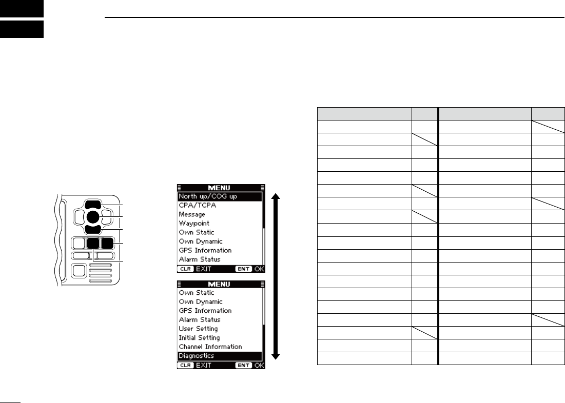
■ General
q Push [MENU] to enter the Menu mode.
w
Push [∫] or [√] to select the desired item, then push [ENT].
e Select the desired option or check the screen contents.
Theproceduresaredescribedonpages29to34.
•Someitemsare not described in this section. See the list to the
right for the specified pages.
r Repeat steps w and e to select or check other items.
t Push [CLEAR] to exit the Menu mode.
[CLEAR]
[ENT]
[MENU]
[∫]
[√]
■ Menu mode items
The Menu mode contains the following items.
Item Ref. Item Ref.
North up/COG up* p. 16 User Setting
CPA/TCPA •RCVMSGBUZZ p. 33
•Alarm p. 29 •InternalGPS p. 33
•SlowWarn p. 29 - SBAS Function p.34
•CPA,TCPA p. 30 - SBAS Search p.34
Message - SBAS Satelite p.34
•RXLog* p. 23 Initial Setting
Waypoint •SetMMSI* pp. 7, 9
•List* p.24 •SetName*
pp. 9, 13
•Add* p.24 •SetCallSign*
pp. 9, 13
•Edit* p. 26 •SetINTGPSPOS* p. 10
•Delete* p. 27 •
Set EXT GPS POS
* p. 10
Own Static p. 30 •SetTypeofShip* p. 10
Own Dynamic p. 31 •SetInput/Output* p. 11
GPS Information p. 31 Channel Information p.34
Alarm Status p. 32 Diagnostics
User Setting •MonitorTest* p.44
•KeyBeep p. 32 •TransponderTest* p.45
•AlarmBuzzer p. 33 •VersionInformation* p.45
*These items are not described in this section. See the specified page.
New2001
29
6
MENU MODE OPERATION
New2001
1
2
3
4
5
6
7
8
9
10
11
12
13
14
15
16
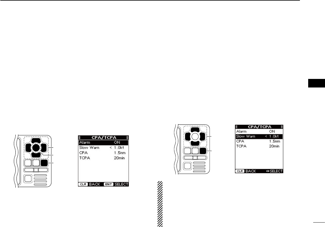
D CPA/TCPA
• Alarm
You can turn the collision alarm function ON or OFF.
q Push [∫] or [√] to select “Alarm.”
w Push [ENT] to toggle this function ON or OFF.
•You can also turn ONthe function bypushing [≈], or OFF by
pushing [Ω].
ON : “COLLISION ALARM” appears on the display, and
the alarm buzzer sounds* repeatedly when an AIS
target is closer than your CPA and TCPA settings, as
explained to page 30. (default)
* The alarm buzzer sounds only when the alarm buzzer
function is turned ON. (p. 33)
OFF : The collision alarm function is OFF.
e Push [CLEAR] to save and return to the Menu mode.
[CLEAR]
[ENT]
[∫], [√],
[Ω], [≈]
• Slow Warn
The GPS receiver calculated COG data of a vessel that is at
anchor or drifting is unreliable, and therefore the CPA and TCPA
data may not be calculated correctly. If a vessel is anchored in
your alarm zone, the unreliable data can cause the collision
alarm to sound many times, even if there is no real danger. To
prevent this, when the anchored vessel’s SOG is less than this
set value, the Slow Warn function assumes that vessel’s COG
is fixed towards your vessel and an alarm will sound.
q Push [∫] or [√] to select “Slow Warn.”
w Push [Ω] or [≈]toinputthevaluebetween0.1and4.9kt
(in 0.1 kt steps), or select OFF. (default: 1.0 kt)
e Push [CLEAR] to save and return to the Menu mode.
[CLEAR]
[∫], [√],
[Ω], [≈]
NOTE: If other vessels at anchor or drifting come into your
alarm zone, the Slow Warn alarm will sound again. Only if
the previous vessel disappears from the Dangerous List
(pp. 6, 17), and then re-enters the list, can a new Slow
Warn or regular alarm sound, depending on the vessels
SOG, or CPA and TCPA. The Slow Warn function operates
in the same way if your vessel is at anchor and other ves-
sels enter your alarm zone area.
30
6MENU MODE OPERATION
New2001
■ Menu mode items
DCPA/TCPA(Continued)
• CPA, TCPA
Enter CPA (Closest Point of Approach) and TCPA (Time to
CPA) values.
These settings help you find a dangerous target to avoid a
collision. The icon blinks on the plotter display and/or the
alarm buzzer sounds, when the AIS target is closer than your
CPA and TCPA settings.
q Push [∫] or [√] to select either “CPA” or “TCPA.”
w Push [Ω] or [≈] to input the value into that item.
•CPA :Between0.1and6.0nm(in0.1nmsteps)
(default: 1.5 nm)
•TCPA:Between1and60minutes(in1minutesteps)
(default: 20 min)
e Repeat steps q and w to input the value into the other
item.
r Push [CLEAR] to save and return to the Menu mode.
[CLEAR]
[ENT]
[∫], [√],
[Ω], [≈]
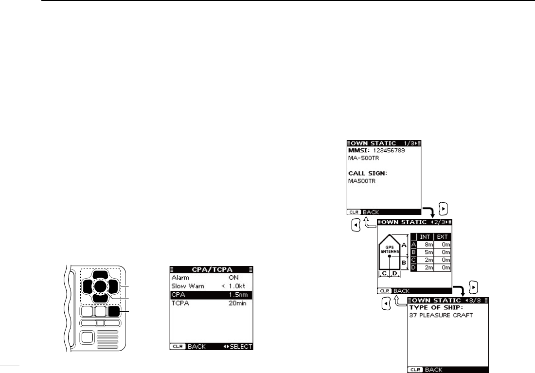
D Own Static
This screen shows your static vessel information such as
MMSIcode,VesselName,CallSign,Internal/ExternalGPS
antenna position and Type of Ship.
q
When the Own Static screen is displayed, push [≈] to se-
lect the next page, or push [Ω] to select the previous page.
w Push [CLEAR] to return to the Menu mode.
31
6
MENU MODE OPERATION
New2001
1
2
3
4
5
6
7
8
9
10
11
12
13
14
15
16
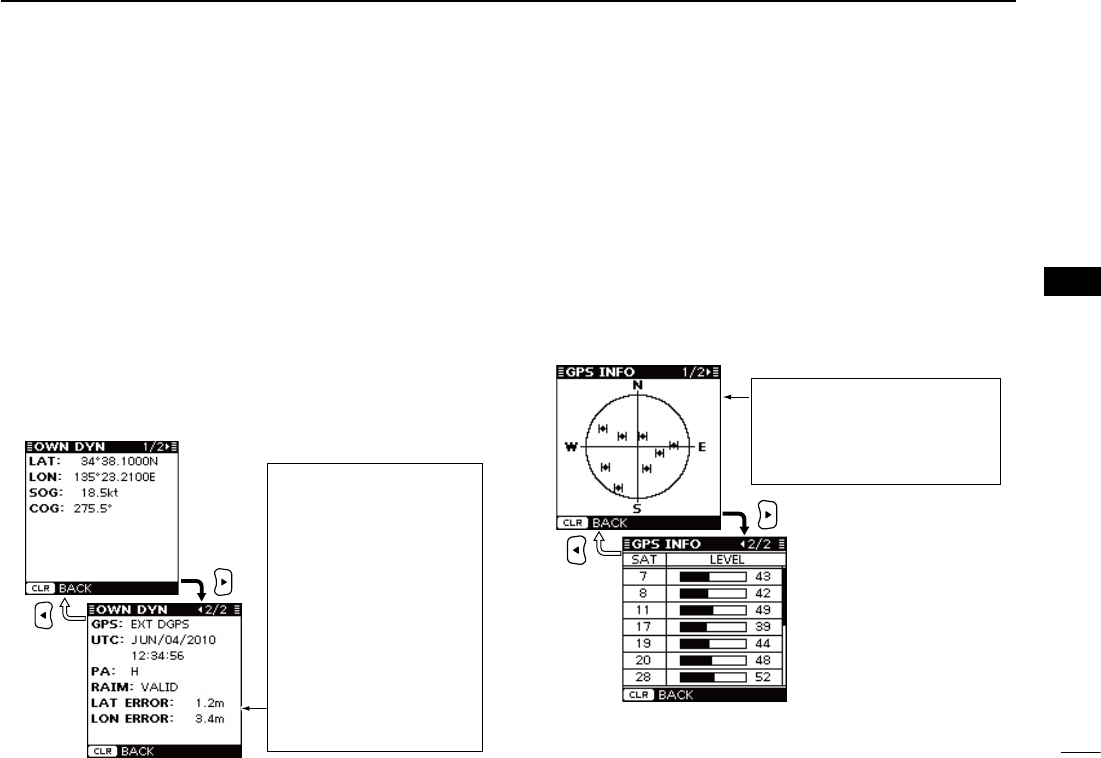
D Own Dynamic
This screen shows your dynamic vessel information such as
Latitude and Longitude data, SOG, COG, GPS receiver type,
UTC date and time, PA, RAIM (Receiver Autonomous Integ-
rity Monitoring) function availability and Latitude and Longi-
tude error data.
•Aninternal GPShasnoRAIMfunction.Whentheinternal GPSis
used, “RAIM,” “LAT ERROR” and “LON ERROR” are not displayed.
•AnexternalGPSrequiresaRAIM
function
. When the external GPS
is used, “RAIM,” “LAT ERROR” and “LON ERROR” are displayed.
q When the Own Dynamic screen is displayed, push [≈] to
select the next page, or push [Ω] to select the previous
page.
w Push [CLEAR] to return to the Menu mode.
D GPS Information
The GPS Information screen shows the viewable GPS satel-
lite’s information, when the internal or external* GPS receiver
is connected.
* Only when the transponder receives the sentence format
“GSA”or“GSV”fromtheexternalGPSreceiver.
q When the GPS Information screen is displayed, push [≈]
to select the next page, or push [Ω] to select the previous
page.
•Theiconsofthesatellites being used, blink.
w Push [CLEAR] to return to the Menu mode.
SAT : Satellite number
LEVEL : Signal strength level
The GPS antenna of your vessel is
located in the center of the
North,
South, East and West screen
, and
the visible GPS satellite icons are
displayed.
When a non-differential GPS
receiver is connected, PA is
normally ‘L.’ However, if the
values of “LAT ERROR” and
“LON ERROR” are less than
5.0 meters (16.4 feet), PA
changes to ‘H.’
When a differential GPS re-
ceiver is connected, PA is
normally ‘H.’ However, if the
values of “LAT ERROR” and
“LON ERROR” are more
than15.0meters(49.2feet),
PA changes to ‘L.’
32
6MENU MODE OPERATION
New2001
■ Menu mode items (Continued)
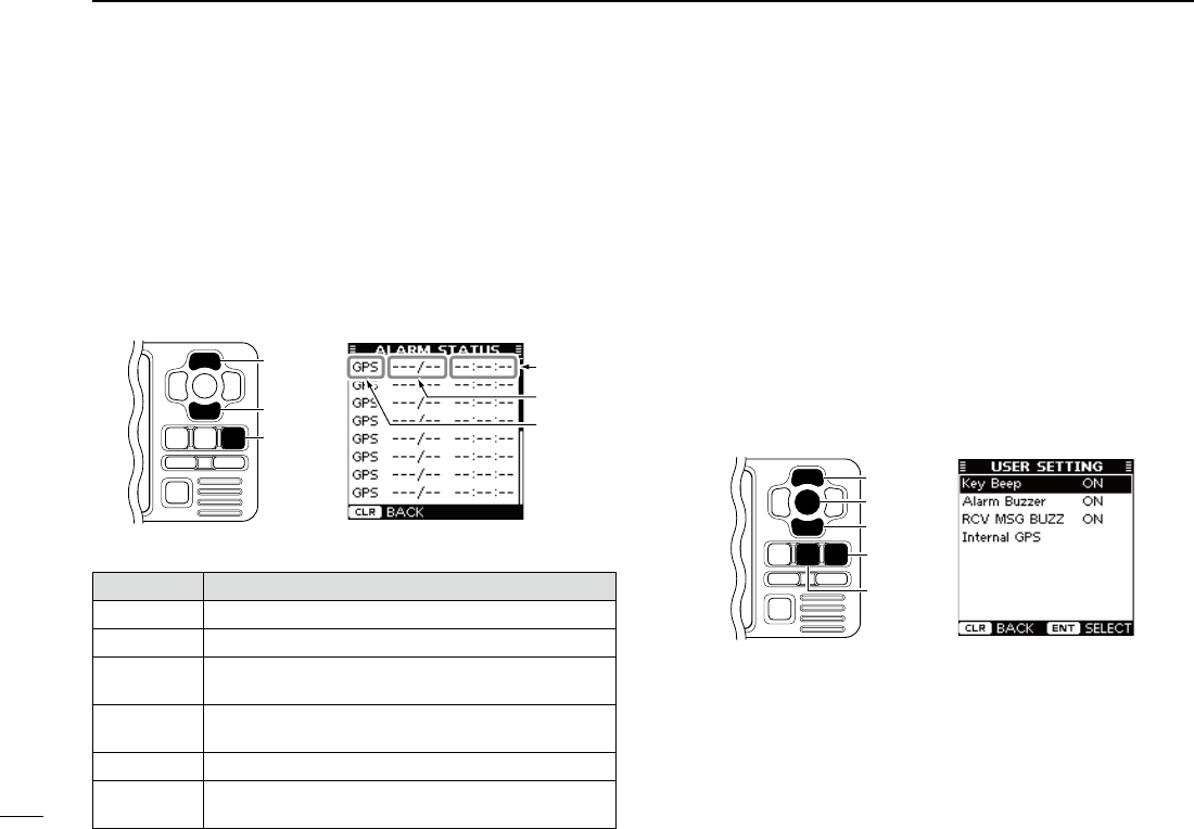
D Alarm Status
The Alarm Status screen shows the type, date and time of the
last 25 malfunctions that were detected.
Even if the alarm buzzer function is turned OFF, the alarm
status is displayed here. (p. 33)
q When the Alarm Status screen is displayed, push [∫] or
[√] to scroll the screen.
w Push [CLEAR] to return to the Menu mode.
Alarm type
Date
Time
[CLEAR]
[∫]
[√]
• Description of the Alarm type
Alarm type Description
GPS Appears when “GPS Malfunction” is detected.
RX Appears when “RX Malfunction” is detected.
CH A Appears when “CH A Noise Level Malfunction” is
detected.
CH B Appears when “CH B Noise Level Malfunction” is
detected.
TX Appears when “TX Malfunction” is detected.
ANT Appears when “Antenna Open or Short Malfunction”
or“AntennaHighVSWRMalfunction”isdetected.
D User Setting
The User setting mode allows you to set the seldom-changed
settings, and you can “customize” the transponder operation
to suit your preferences and operating style.
q Push [MENU] to enter the Menu mode.
w Push [∫] or [√] to select “User Setting,”
then push [ENT].
e
Push [∫] or [√] to select the desired item, then push [ENT].
r Select the desired option, shown in the Menu below.
The procedures are described to the right and continued
on the next page.
t Repeat steps e and r to select other items.
y Push [CLEAR] to save and return to the Menu mode.
u Push [CLEAR] to exit the Menu mode.
[CLEAR]
[ENT]
[∫]
[√]
[MENU]
<SETTING ITEMS>
• Key Beep
You can select the silent operation, or you can have confirma-
tion beeps sound when you push a key.
➥ Push [ENT] to toggle this function ON or OFF.*
ON : A beep sounds when pushing a key. (default)
OFF : The key beep is OFF. (Silent operation)
33
6
MENU MODE OPERATION
New2001
1
2
3
4
5
6
7
8
9
10
11
12
13
14
15
16
• Alarm Buzzer
Turn the alarm buzzer function ON or OFF.
➥ Push [ENT] to toggle this function ON or OFF.*
ON : The alarm buzzer sounds when a malfunction oc-
curs or an AIS target is closer than your CPA and
TCPA settings*. (default)
* The alarm buzzer sounds only when the collision alarm
function is turned ON. (p. 29)
OFF : The alarm buzzer is OFF.
• Received Message Buzzer (RCV MSG BUZZ)
Turn the received message buzzer function ON or OFF.
➥ Push [ENT] to toggle this function ON or OFF.*
ON : The buzzer sounds three times when a message is
received. (default)
OFF : The received message buzzer is OFF.
* You can also turn ON the function by pushing [≈], or OFF
by pushing [Ω].
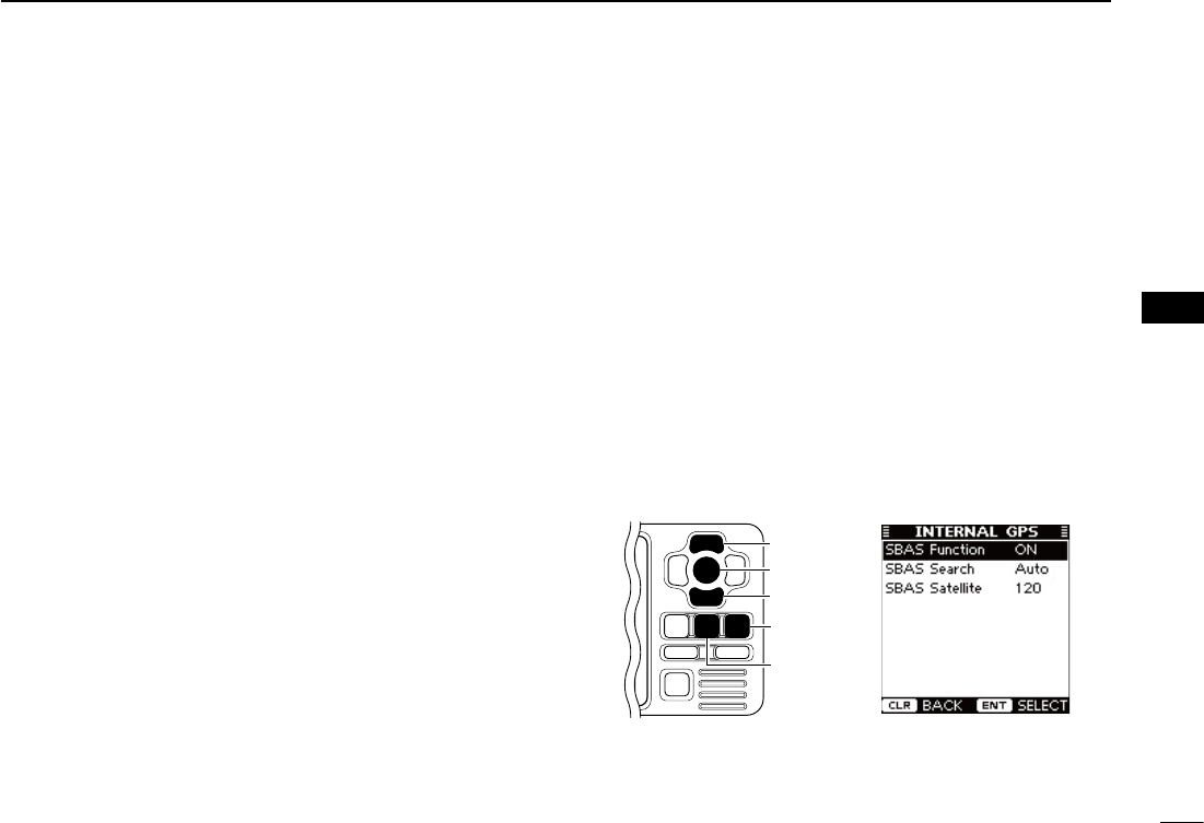
• Internal GPS
The Internal GPS setting mode allows you to set the internal
GPS settings.
q Push [MENU] to enter the Menu mode.
w Push [∫] or [√] to select “User Setting,”
then push [ENT].
e Push [∫] or [√] to select “Internal GPS,”
then push [ENT].
r
Push [∫] or [√] to select the desired item, then push [ENT].
t Select the desired option, shown in the Menu below.
The procedures are described to the right and continued
on the next page.
y Repeat steps r and t to select other items.
u Push [CLEAR] to save and return to the User Setting
mode.
i Push [CLEAR] twice to exit the Menu mode.
[CLEAR]
[ENT]
[∫]
[√]
[MENU]
34
6MENU MODE OPERATION
New2001
■ Menu mode items
D User Setting (Continued)
<SETTING ITEMS>
- SBAS (Satellite Based Augmentation System) Function
The SBAS transmits signals to correct errors and improve
accuracy and reliability in data received from regular GPS
satellites. When this function is ON, the transponder uses the
corrected data.
➥ Push [ENT] to toggle this function ON or OFF.
•You can also turn ONthe function bypushing [≈], or OFF by
pushing [Ω].
ON : The SBAS function is ON. (default)
OFF : The SBAS function is OFF.
- SBAS Search
Set the SBAS search function to “Manual” or “Auto.”
This function should normally be set to “Auto.”
➥ Push [ENT] to select either “Manual” or “Auto.”
•Youcanalsoselecttheoptionbypushing[Ω] or [≈].
Manual : You have to manually select the SBAS satellite.
This option can be useful when your vessel is in
an area where 2 satellite zones overlap.
Auto : The transponder automatically searches for the
SBAS satellite that is determined according to the
position of your vessel. (default)
- SBAS Satellite
When “Manual” option is selected in the SBAS Search item,
you should manually select the SBAS Satellite which covers
the zone your vessel is monitoring.
➥ Push [Ω] or [≈] to select an SBAS Satellite number be-
tween 120 and 138. (default: 120)
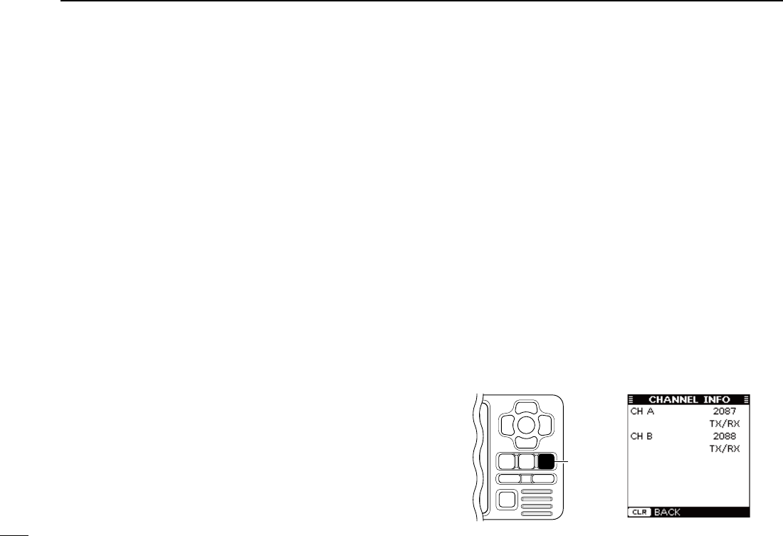
D Channel information
The channel information screen shows the channels 2087
and 2088 information in which safety-related messages are
transmitted to, and received from, the AIS targets.
The channel to be used is automatically set according to the
message received from an AIS Base Station.
➥ Push [CLEAR] to return to the Menu mode.
[CLEAR]
New2001
35
7
INSTALLATION AND CONNECTIONS
New2001
1
2
3
4
5
6
7
8
9
10
11
12
13
14
15
16
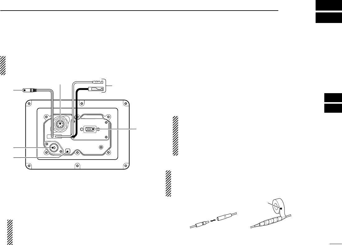
■ Connections
About the installation distance from the compass:
KEEP the transponder at least 1 m (3.3 ft) away from the
vessel’s magnetic navigation compass.
q
t
y
r
e
w
q CLONING CABLE CONNECTOR
Connects the cloning cable from this connector to a PC.
Ask your dealer for details.
w INTERNAL GPS RECEIVER CONNECTOR
Connects to the MXG-5000 to receive position data and
transmit it with other AIS information.
NOTE: Important notes and how to install the MXG-
5000 are described on the instruction sheet that comes
with it. Be sure to read them before installing and oper-
ating the MXG-5000.
e DC POWER CONNECTOR
Connects the supplied DC power cable between this con-
nectoranda12Vpowersource.
r HIGH-DENSITY D-SUB 15 PIN (NMEA IN/OUT)
Connects an Icom MarineCommander™ system, naviga-
tion equipment, external GPS receiver, etc. using the sup-
pliedOPC-2014n m e a c o n n e c t o r c a b l e .
See page 37 for the pin assignment.
Requirements of the external GPS:
•The datum of the external GPS receiver must be
“WGS-84.”
•GBSsentencecanbeinputusingtheRAIMfunction.
•The external GPS antenna must be installed within
26 m (85.3 ft) of the internal GPS antenna.
CAUTION: After connecting the DC power cable and
NMEA connector cable leads, cover the cable and leads
with a rubber vulcanizing tape, to prevent water seeping
into the transponder.
Rubber vulcanizing tape

New2001
36
7INSTALLATION AND CONNECTIONS
New2001
■ Connections (Continued)
t GROUND TERMINAL
Connects to a vessel ground to prevent electrical shocks
and interference from other equipment occurring. Use a
self-tapping screw (3 × 8 mm).
y ANTENNA CONNECTOR
ConnectstoamarineVHFantennawithaPL-259connec-
tor for AIS signal transmission and reception. (p. 38)
CAUTION: Transmitting without an antenna may dam-
age the transponder.
D High-density D-sub 15 pin assignment
qtrew
y!0 oiu
!1!5 !4 !3 !2
NOTE: The OPC-2014 n m e a c o n n e c t o r c a b l e has 15
leads, numbered 1 to 15.
Rear panel view

37
7
INSTALLATION AND CONNECTIONS
New2001
1
2
3
4
5
6
7
8
9
10
11
12
13
14
15
16
PIN No. PIN No. SPECIFICATIONS SENTENCE FORMAT DESCRIPTION
1 GND — — Connects to ground.
2 NMEA1 OUT (–) •Outputlevel
:5V/40mAmax.
(RS-422balancedtype)
DSC, RMC, GGA, VTG, GSA,
GSV, GBS, DTM, DSE, GNS,
GLL
ConnectstotheNMEAinput/outputconnectorof
a transceiver to transmit an Individual DSC call,
or to connect to a GPS receiver. (p. 39)
The data communication speed (baud rate) can
beselectedbetween4800bps(IEC61162-1)and
38400 bps (IEC61162-2) for each Input/Output
port.
(Default:4800bps)
3NMEA1OUT(+)
4NMEA1 IN (–) •Inputlevel
: Less than 2 mA
(at2Vapplied)
RMC, GGA, VTG, GSA, GSV,
GBS†, DTM, GNS, GLL
5NMEA1IN(+)
6 ALERT1 •Loadrating
: DC24V/500mAmax. —
A short occurs between pins 6 and 11 when the alarm
buzzer sounds if a malfunction occurs, or an AIS
target is closer than your CPA and TCPA settings.
11 ALERT2
7 NMEA2 OUT (–) Same as pins 2 and 3
VDM,VDO,ALR,ACA,ACS,TXT,
RMC*,GGA*,GNS*,GLL*,VTG*,
GSA*,GSV*,GBS*,DTM*
Connects to the Icom MarineCommander™ sys-
tem or to a GPS receiver.
The data communication speed (baud rate) is
fixed to
38400bps
(IEC61162-2)foreachInput/
Output port.
8NMEA2OUT(+)
9 NMEA2 IN (–) Sameaspins4and5
RMC, GGA, VTG, GSA, GSV,
GBS†, DTM, GNS, GLL
10 NMEA2IN(+)
12 NMEA3 OUT (–) Same as pins 2 and 3
RMC, GGA, VTG, GSA, GSV,
GBS, DTM, GNS, GLL
Connects to a piece of navigation equipment or
to a GPS receiver.
The data communication speed (baud rate) can
beselectedbetween4800bps(IEC61162-1)and
38400bps(IEC61162-2)foreachInput/Output
port.
(Default:4800bps)
13 NMEA3OUT(+)
14 NMEA3 IN (–)
Sameaspins4and5
RMC, GGA, VTG, GSA, GSV,
GBS†, DTM, GNS, GLL
15 NMEA3IN(+)
†When a received GPS signal includes no GBS sentence, the transponder will not receive the signal from the external GPS receiver.
* Sent only when the “AIS+GPS”optionissetin“AISOutput.”(p.12)
New2001
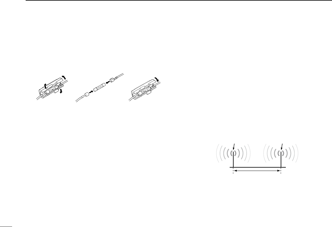
38
7INSTALLATION AND CONNECTIONS
New2001
■ Fuse replacement
One fuse is installed in the DC power cable. If the fuse blows,
track down the source of the problem, have it repaired, and
replace the damaged fuse with a new one of the proper rat-
ing.
Fuse rating: 3 A
■ About the VHF antenna
A key element in the performance of any communication sys-
temistheantenna.TheVHFAIS/radioantennasshouldbe
mounted in a location that has a clear, unobstructed view in
all directions and as far away from interference as possible,
for the best reception and transmission. When selecting a
mounting location, follow the guidelines below.
-Mount theVHF AIS/radio antennas at least 3 m (9.85 ft.)
away from each other.
-MounttheVHFAIS/radioantennasashighaspossible.
- Be sure the location is out of the radar beam.
- Be sure the location will not be shaded by a random antenna
or mast.
VHFAISantenna VHFradioantenna
At least 3 m (9.85 ft.)

39
7
INSTALLATION AND CONNECTIONS
New2001
1
2
3
4
5
6
7
8
9
10
11
12
13
14
15
16
• Antenna connector
The antenna uses a PL-259 connector.
q Slide the coupling ring
down. Strip the cable jacket
and tin the shield.
w Strip the cable as shown at
left. Tin the center conduc-
tor.
e Slide the connector body
on and solder it.
r
Screw the coupling ring onto
the connector body.
NOTE: There are many publications covering antennas
and their proper installation. Check with your local dealer
for more information and recommendations.
■ Transceiver connection
Connect the transponder and a transceiver using the
OPC-2014n m e a c o n n e c t o r c a b l e . After connecting, an In-
dividual DSC call can be made to the AIS target using the
transponder without entering the target’s MMSI code. (p. 22)
Seetheleaetthatcomeswiththetransponderfordetailsof
the transceivers which can operate with this function.
Inthissection,theconnectinginstructionsoftheIC-M504*1,
IC-M505*1, IC-M603*2 and IC-M604*2 are described as an
example. See the instruction manual of each for transceiver’s
connecting instructions.
*1 Requires the first two digits of the serial number to be “21” or
higher.
*2 Requires the first two digits of the serial number to be “31” or
higher.
☞ Continued on the next page.
30 mm
10 mm (tin here)
10 mm
1–2 mm
solder solder
tin
Coupling ring
30 mm (13⁄16 in) 10 mm (13⁄32 in) 1–2 mm (1⁄32–3⁄32 in)
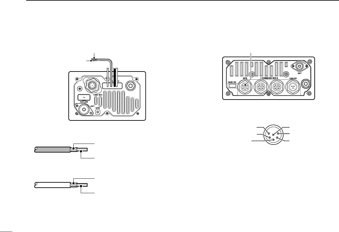
40
7INSTALLATION AND CONNECTIONS
New2001
■ Transceiver connection (Continued)
D IC-M504/M505
Inner conductor: NMEA OUT (+)
Connects to lead 5 of OPC-2014.
Outer conductor: NMEA OUT (−)
Connects to lead 4 of OPC-2014.
Inner conductor: NMEA IN (+)
Connects to lead 3 of OPC-2014.
Outer conductor: NMEA IN (−)
Connects to lead 2 of OPC-2014.
NMEA IN LEAD (Red)
NMEA OUT LEAD
(White)
• NMEA IN LEAD (Red)
• NMEA OUT LEAD (White)
Transceiver’s rear panel
D IC-M603/M604
r NMEAOUT (+)
e NMEAOUT (–)
w NMEAIN (+)q NMEAIN (–)
SP (+)
SP (–)
r NMEA OUT (+)
Connects to lead 5 of OPC-2014.
e NMEA OUT (−)
Connects to lead 4 of OPC-2014.
w NMEA IN (+)
Connects to lead 3 of OPC-2014.
q NMEA IN (−)
Connects to lead 2 of OPC-2014.
GPS receiver/External speaker connector
• GPS receiver/External speaker connector
Transceiver’s rear panel
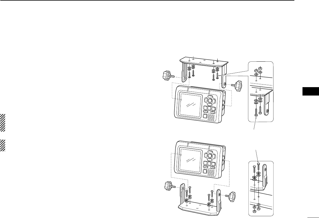
4141
7
INSTALLATION AND CONNECTIONS
New2001
1
2
3
4
5
6
7
8
9
10
11
12
13
14
15
16
■ Mounting the transponder
D Using the mounting bracket
The universal mounting bracket supplied with your transpon-
der allows overhead or dashboard mounting.
qMount the bracket securely with the 4 supplied screws
(5 × 20 mm) to a surface which is more than 10 mm (13⁄32 in)
thick and can support more than 3 kg (6 lb 61 oz).
w Attach the transponder to the bracket so that the face of
the transponder is at 90° to your line of sight when operat-
ing it.
About the installation distance from the compass:
KEEP the transponder at least 1 m (3.3 ft) away from the
vessel’s magnetic navigation compass.
NOTE: Check the installation angle; the function display
may not be easy to read at some angles.
• OVERHEAD MOUNTING
• MOUNTING ON THE BOARD These bolts show a
mounting example only.
Not supplied with acces-
sories.
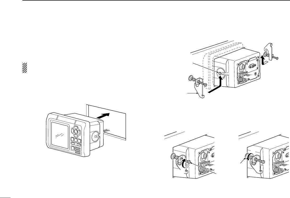
42
7INSTALLATION AND CONNECTIONS
New2001 New2001
■ MB-75 installation
An optional MB-75 f l u s h m o u n t k i t is available for mount-
ingthetranspondertoaatsurface,suchasaninstrument
panel.
KEEP the transponder at least 1 m (3.3 ft) away from your
vessel’s magnetic navigation compass.
qUsingthetemplateonthepage47,carefullycutaholeinto
the instrument panel (or wherever you plan to mount the
transponder).
w Slide the transponder through the hole.
e Attach the 2 supplied bolts (M5 × 8 mm) on either side of
the transponder.
r Attach the clamps on either side of the transponder.
•Make sure that the clamps align parallel to the transponder’s
body.
r
r
Clamp
Bolt
t Tighten the end bolts on the clamps (rotate clockwise) so
that the clamps press firmly against the inside of the in-
strument control panel.
y Tighten the locking nuts (rotate counterclockwise) so that
the transponder is securely mounted in position.
End bolt
t
Locking nut
y
u Connect the antenna, power cable, GPS receiver and
OPC-2014,thenreturntheinstrumentcontrolpaneltoits
original place.

43
8
MAINTENANCE
New2001
1
2
3
4
5
6
7
8
9
10
11
12
13
14
15
16
PROBLEM POSSIBLE CAUSE SOLUTION REF.
The transponder does not
turn ON.
•Badconnectionatthepowersource. •Check the connection to the transpon-
der. p. 35
Cannot transmit. •1 minute has not passed from turning
ON the transponder power.
•Wait for 1 minute from turning ON the
transponder power. —
The plotter display does not
appear.
•Theresults ofthe openingtestis“NG”
(No Good).
•The transponder is still searching for
GPS satellites.
•Holddown[POWER•BRILL] for 1 sec-
ond to turn the power OFF, then push to
turn it ON again to reset the transpon-
der.
•Wait until the transponder detects a
GPS satellite.
pp. 7,
14
—
The GPS search display does
not disappear.
•The GPS receiver is not connected to
the transponder.
•Connect the GPS receiver to the tran-
sponder. p. 35
An error beep sounds after
pushing [DSC].
•AnAIStargetisnotselected.
•A transceiver is not connected to the
transponder.
•SelectthedesiredAIStargetordisplay
the detail screen of the AIS target.
•Connectthetransceivertothetranspon-
der.
pp. 15,
16, 17
p. 39
The collision alarm does not
sound.
•The collision alarm function is OFF.
•ThealarmbuzzerfunctionisOFF.
•Turn ON the collision alarm function.
•TurnONthealarmbuzzerfunction.
p. 29
p. 33
■ Troubleshooting
The following chart is designed to help you correct problems
which are not equipment malfunctions.
If you are unable to locate the cause of a problem or solve
it through the use of this chart, contact your nearest Icom
Dealer or Service Center.
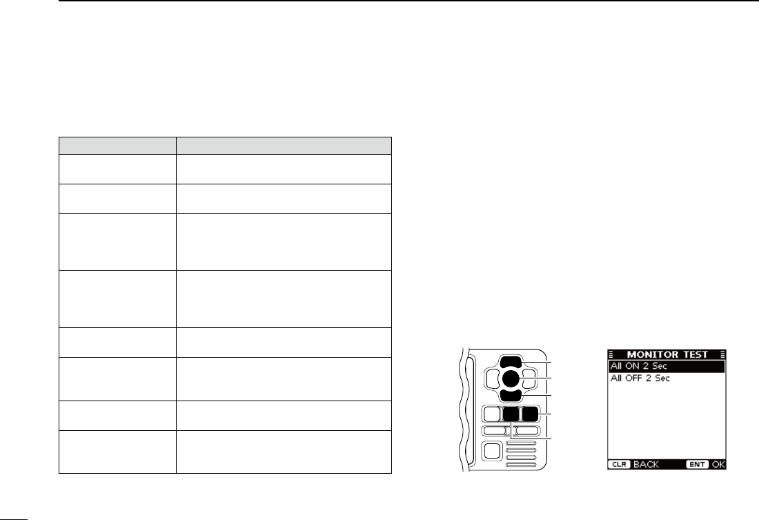
44
8MAINTENANCE
New2001
■ Error message
Error message is displayed when a malfunction occurs that
has an error message programmed for it.
Message contents Description
GPS MALFUNCTION
NO GPS DATA
Appears when no GPS data is received.
RX MALFUNCTION
NORCV
Appears when the transponder receive cir-
cuit has failed.
RX MALFUNCTION
CHANOISELEVEL
Appears when the transponder receives
excessively strong noise signals from an-
other piece of navigation equipment on
Channel A.
RX MALFUNCTION
CHBNOISELEVEL
Appears when the transponder receives
excessively strong noise signals from an-
other piece of navigation equipment on
Channel B.
TX MALFUNCTION
NO TX POWER
Appears when no RF power is output, or
the transmit circuit has failed.
TX MALFUNCTION
CONTINUOUS TX
Appears when the protective circuit cuts off
the AIS signal after 1 second of continuous
transmission.
ANT MALFUNCTION
OPEN OR SHORT
Appears when the antenna is open or
shorted.
ANT MALFUNCTION
HIGHVSWR
AppearswhenthehighVSWR*isdetected
(the antenna is mismatched).
*VoltageStandingWaveRatio
■ Diagnostics
There are two types of diagnostic tests performed — Monitor
test,TranspondertestandVersioninformation.
• Monitor Test
You can check whether all LCD segments turn ON and OFF
properly.
q Push [MENU] to enter the Menu mode.
w Push [∫] or [√] to select “Diagnostics,”
then push [ENT].
e Push [∫] or [√] to select “Monitor Test,”
then push [ENT].
r Push [∫] or [√] to select “All ON 2 Sec” or “All OFF 2 Sec,”
then push [ENT].
•All ON 2 Sec : All LCD segments turn ON for 2 seconds.
•All OFF 2 Sec : All LCD segments turn OFF for 2 seconds.
t Push [CLEAR] to return to the “DIAGNOSTICS” screen.
y Push [CLEAR] twice to exit the Menu mode.
[CLEAR]
[ENT]
[∫]
[√]
[MENU]
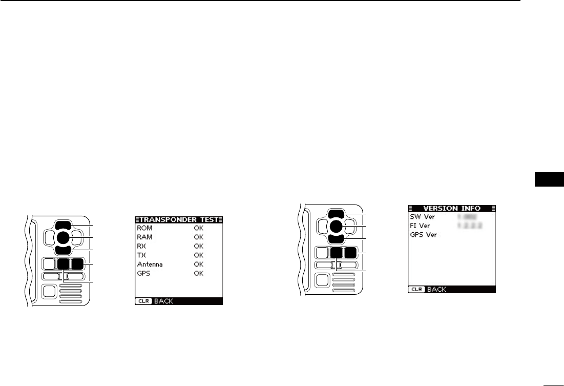
45
8
MAINTENANCE
New2001
1
2
3
4
5
6
7
8
9
10
11
12
13
14
15
16
• Transponder Test
You can check whether the transponder units work properly.
q Push [MENU] to enter the Menu mode.
w Push [∫] or [√] to select “Diagnostics,”
then push [ENT].
e Push [∫] or [√] to select “Transponder Test,”
then push
[ENT].
r ThescreenshowstheresultsoftheROM,RAM,RX/TX
unit, antenna and GPS receiver tests; “OK” or “NG” (No
Good).
t Push [CLEAR] to return to the “DIAGNOSTICS” screen.
y Push [CLEAR] twice to exit the Menu mode.
[CLEAR]
[ENT]
[∫]
[√]
[MENU]
• Version Information
You can check the version information of SW (Software), FI
(Function Image) and the Internal GPS receiver.
q Push [MENU] to enter the Menu mode.
w Push [∫] or [√] to select “Diagnostics,”
then push [ENT].
e Push [∫] or [√]toselect“VersionInformation,”
then push
[ENT].
r The screen shows the version information of each item.
t Push [CLEAR] to return to the “DIAGNOSTICS” screen.
y Push [CLEAR] twice to exit the Menu mode.
[CLEAR]
[ENT]
[∫]
[√]
[MENU]
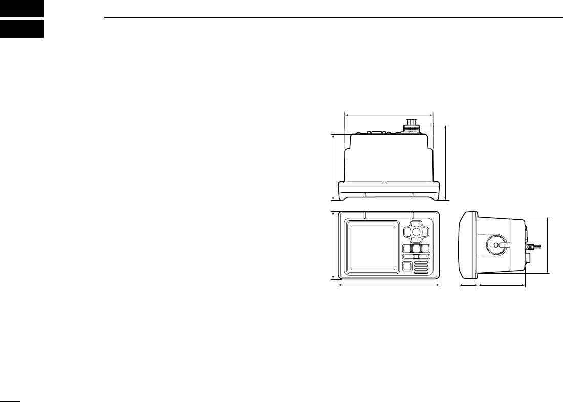
New2001
46
New2001
SPECIFICATIONS AND OPTION
9
■ Specications
D General
•Frequencycoverage :161.975,162.025MHz(default)
156.025–162.025 MHz
•Typeofemission :
16K0GXW (GMSK)
•Currentdrain(at12Vnominal) :TX:1.5A,RX:0.7A
•Powersupplyrequirement :9.6to15.6VDC
(negative ground)
•Operatingtemperaturerange :–20°Cto+60°C;–4°Fto+140°F
•Antennaimpedance :50ø nominal
•Intermediatefrequency
AIS1 :
1st:21.700MHz,2nd:450kHz
AIS2 :
1st:30.875MHz,2nd:450kHz
•Dimensions :165(W)× 110(H) × 123.3(D) mm,
(Projections not included) 6 1⁄2(W) ×411⁄32(H) ×427⁄32(D) in
•Weight :Approximately1.0kg;2lb20oz
•I/Oconnector :High-densityD-sub15pin
D Transmitter
•Outputpower :2W
•Modulationsystem :GMSK
•
Conducted
Spurious emissions : Less than –36 dBm
D Receiver
•Sensitivity(20% Packet Error Rate) : –110 dBm
•Intermodulationrejectionratio :Morethan65dB
•
Spurious response rejection ratio
:Morethan74dB(AIS)
More than 70 dB (DSC)
•Adjacentchannelselectivity :Morethan70dB
•
Conducted spurious emission
: Less than –57 dBm (AIS)
This equipment meets IEC 62287-1 specifications.
D Dimensions
Unit: mm (inch)
110 (4 11⁄32) 108.4 (4 9⁄32)
165 (6 1⁄2)
145 (5 23⁄32)
31.4
(1 1⁄4)
91.4 (3 19⁄32)
77 (3 1⁄32)
123.3 (4 27⁄32)
All stated specifications are subject to change without notice or obligation.
■ Option
• MB-75 f l u s h m o u n t k i t
Used to mount the transponder to a panel.
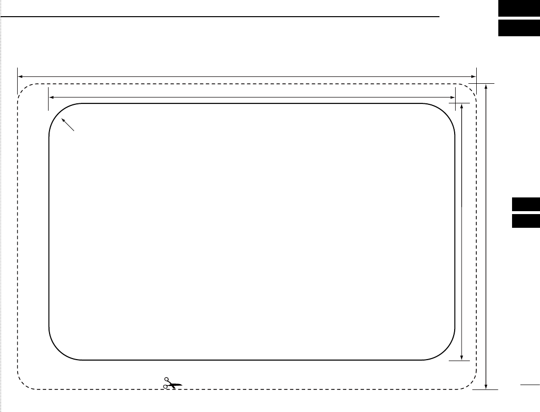
47
10
TEMPLATE
New2001
1
2
3
4
5
6
7
8
9
10
11
12
13
14
15
16
Cut here
Unit: mm (inch)
165 (6 1⁄2)
110 (4 11⁄32)
146 (5 3⁄4)
92.4 (3 5⁄8)
R12 (Max.)
New2001
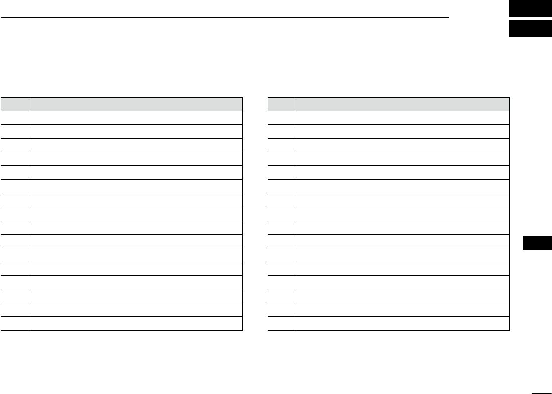
49
11
AtoN CODE AND DESCRIPTION
New2001
1
2
3
4
5
6
7
8
9
10
11
12
13
14
15
16
Code Description
0DEFAULT, TYPE OF ATON NOT SPECIFIED
1REFERENCE POINT
2RACON
3OFF SHORE STRUCTURE
4SPARE
5LIGHT, WITHOUT SECTORS
6LIGHT, WITH SECTORS
7LEADING LIGHT FRONT
8LEADING LIGHT REAR
9BEACON, CARDINAL N
10 BEACON, CARDINAL E
11 BEACON, CARDINAL S
12 BEACON, CARDINAL W
13 BEACON, PORT HAND
14 BEACON, STARBOARD HAND
15 BEACON, PREFERRED CHANNEL PORT HAND
Code Description
16 BEACON, PREFERRED CHANNEL STARBOARD HAND
17 BEACON, ISOLATED DANGER
18 BEACON, SAFE WATER
19 BEACON, SPECIAL MARK
20 CARDINAL MARK N
21 CARDINAL MARK E
22 CARDINAL MARK S
23 CARDINAL MARK W
24 PORT HAND MARK
25 STARBOARD HAND MARK
26 PREFERRED CHANNEL PORT HAND
27 PREFERRED CHANNEL STARBOARD HAND
28 ISOLATED DANGER
29 SAFE WATER
30 SPECIAL MARK
31 LIGHTVESSEL/LANBY
The following table shows all the AtoN codes which appear
on the detail screens of an “AtoN.” (p. 21)

MEMO
New2001

MEMO
New2001
1
2
3
4
5
6
7
8
9
10
11
12
13
14
15
16
1-1-32Kamiminami,Hirano-ku,Osaka547-0003,Japan
New2001
A-6860D-1EX
Printed in Japan
© 2010 Icom Inc.
Printed on recycled paper with soy ink.
< Intended Country of Use >
AT
FI
IT
PL
GB
RO
BE
FR
LV
PT
IS
TR
CY
DE
LT
SK
LI
HR
CZ
GR
LU
SI
NO
DK
HU
MT
ES
CH
EE
IE
NL
SE
BG
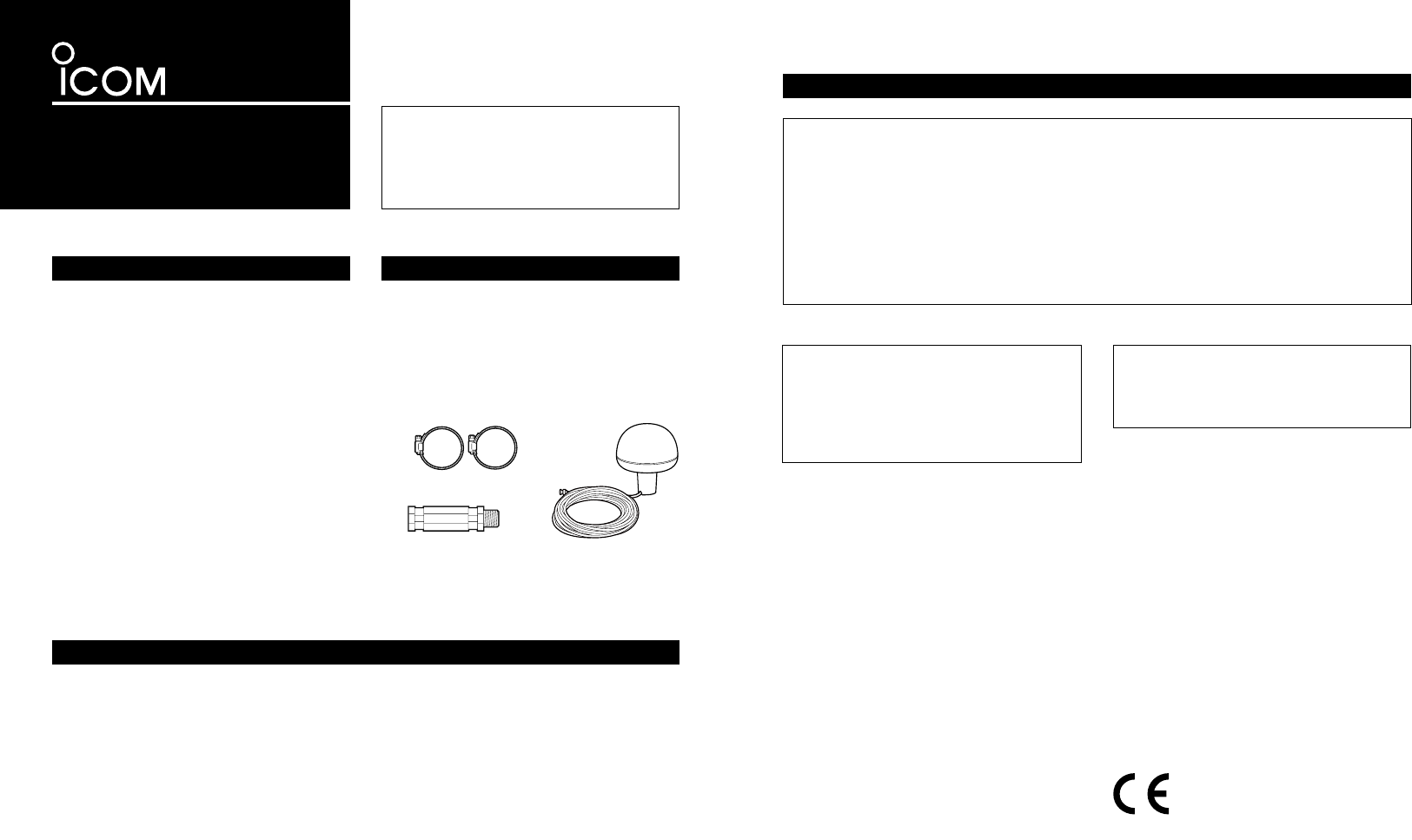
INSTRUCTIONS
GPS RECEIVER
MXG-5000
Thank you for purchasing the MXG-5000
gps receiver.
Please read these instructions thoroughly
before installing and operating the GPS
receiver.
PRECAUTIONS
For CLASS A UNINTENTIONAL RADIATORS
This equipment has been tested and found to comply with the limits for a Class A digital device,
pursuant to part 15 of the FCC Rules. These limits are designed to provide reasonable protection
against harmful interference when the equipment is operated in a commercial environment. This
equipment generates, uses, and can radiate radio frequency energy and, if not installed and used in
accordance with the instruction manual, may cause harmful interference to radio communications.
Operation of this equipment in a residential area is likely to cause harmful interference in which
case the user will be required to correct the interference at his own expense.
NEVER immerse the GPS receiver in water. The
GPS receiver meets IPX6 requirements for high-
pressure water jet resistance. However, once it
has been dropped, high-pressure water jet resis-
tance cannot be guaranteed because of possible
damage to its case or the waterproof seal.
DO NOT use or place the GPS receiver in
areas with temperatures below –20°C (–4°F)
or above +60°C (+140°F).
DO NOT use chemical agents such as benzine
or alcohol when cleaning, as they can damage
the GPS receiver’s surfaces.
The GPS receiver is for Icom MarineCommander™
only! —Other manufacturer’s equipment may
have different pin assignments and can damage
the equipment or GPS receiver if attached.
Item Qty.
q Hose clamp (HAS-40) .......................... 2
w Extension pipe (2273 pipe) .................. 1
e GPS receiver ........................................1
FCC INFORMATION
CAUTION: Changes or modifications not
expressly approved by the party responsible
for compliance could void the user’s authority
to operate the equipment.
The GPS receiver complies with
the essential requirements of
the 2004/108/EC directive for
Electromagnetic Compatibility.
This compliance is based upon the harmonised
CENELEC generic standard EN60945 Ed4.0:
2002, EN60950-1 Ed2.0: 2005, EN61162-1
Ed3.0: 2007.
This device complies with Part 15 of the FCC
Rules. Operation is subject to the following two
conditions: (1) this device may not cause harm-
ful interference, and (2) this device must ac-
cept any interference received, including inter-
ference that may cause undesired operation.
SUPPLIED ACCESSORIES
• Power supply voltage : 4.75 to 5.25 V DC
(supplied from the
MarineCommander™)
• Operating temp. range : −20˚C to +60˚C;
−4˚F to +140˚F
• Relative humidity : Less than 95%
(at +35˚C;
+95˚F)
• Dimensions :
140(d)×157.2(H)
mm;
51⁄2(d)×63⁄16(H) in.
• Weight (approx.) : 710 g; 1.57 oz
• Cable length (approx.) : 10 m; 32 ft. 93⁄4 in.
• Receiving frequency : 1575.42 MHz
• Receiving channels : 12
• Receiving codes : L1, C/A-code, SPS
• Satellite differential type
:
WAAS, EGNOS, MSAS
• TTFF (Time to First Fix)
Cold start (typical) : 40 sec.
Hot start (typical) : 4 sec.
SPECIFICATIONS
All stated specifications are subject to change without notice or obligation.
q
w
e
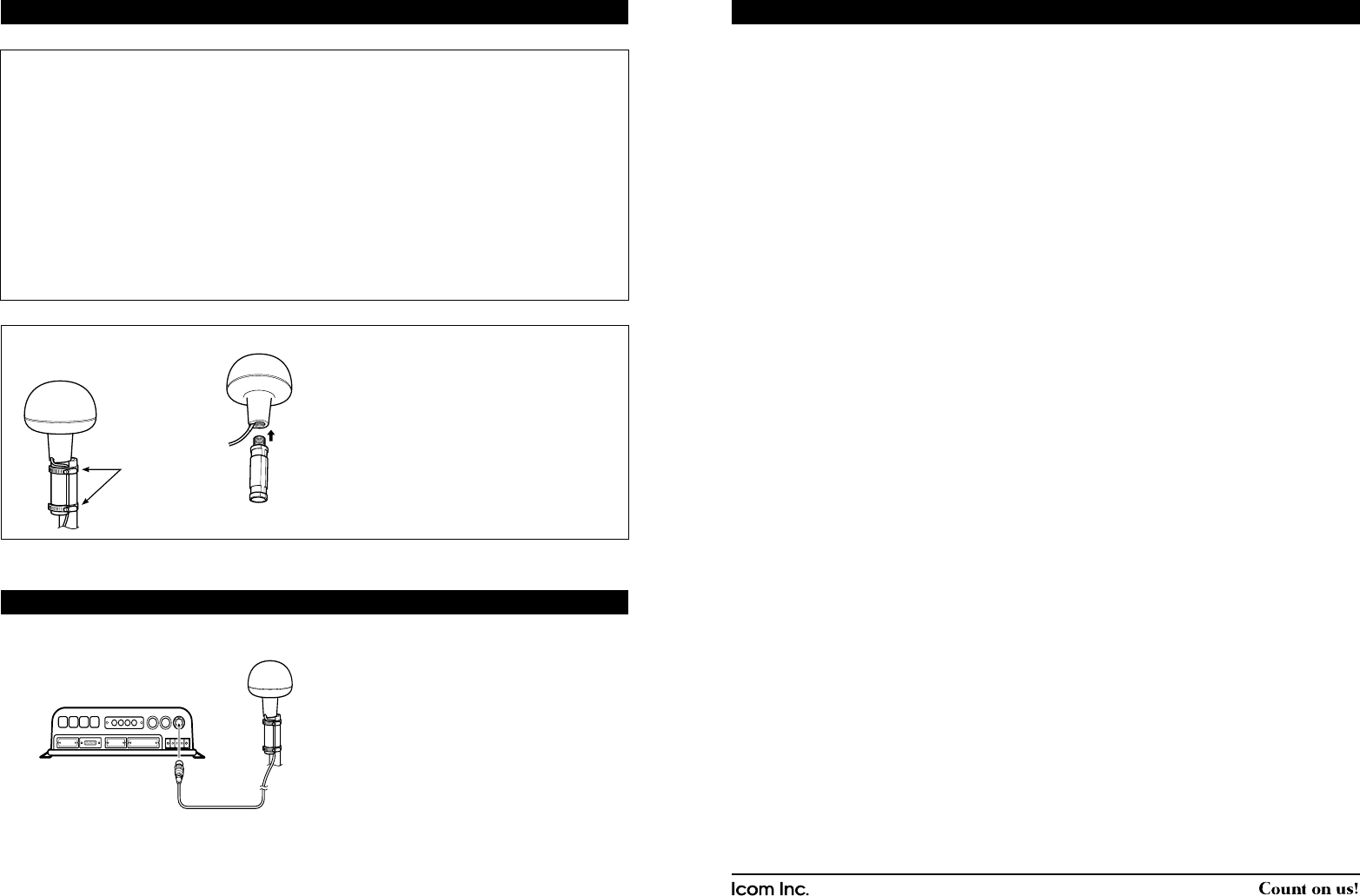
About calculating position
The GPS receiver acquires signals from GPS
satellites. It calculates its position by the orbit
information of the GPS satellites and needs to
measure the distance between itself and three
or more GPS satellites to obtain a reliable posi-
tion. The GPS receiver acquires all available
satellites when it is first powered up, powered off
for a long time, or powered up again at a place
a long way from when it was last powered off.
Normally, it takes approximately 1 minute for de-
termining a position.
In places where the GPS signals cannot reach
the GPS receiver, such as around tall buildings,
it may show position errors (misplacement) or
no position reading at all.
As the satellites are continuously moving, mea-
surement of the position or time by the GPS
receiver may take a while, and/or no position
reading can be made in some instances. Even if
the GPS receiver acquires signals from three or
more GPS satellites, it may take a longer time to
determine a position depending on the satellite
locations.
About Almanac and Ephemeris Data
To reduce the time for calculating position, the
GPS receiver stores the Almanac Data (the orbit
course/orbital parameters of the satellites) in its
internal memory. When the GPS receiver is left
with the power OFF for a long time, it needs to
acquire the Almanac Data again. In this case,
the GPS receiver starts as a “cold” start.
The GPS receiver stores Ephemeris Data of the
satellite’s orbital course, and refers to this data
when it is turned OFF for a short time.
This is called a “hot” start, and uses the Ephem-
eris Data that is valid to within less than 4 hours.
1-1-32 Kamiminami, Hirano-ku, Osaka 547-0003, Japan. A-6747H-1EX-q Printed in Japan
© 2009–2010 Icom Inc.
Icom, Icom Inc. and the Icom logo are registered trademarks of Icom Incorporated (Japan) in Japan, the United
States, United Kingdom, Germany, France, Spain, Russia and/or other countries.
MarineCommander is a trademark of Icom Incorporated.
ATTENTION
MOUNTING
Location precision
The GPS receiver automatically calculates its
position when it acquires signals from three or
more GPS satellites.
The GPS satellite’s measurement error is about
±10 meters, however this can vary up to several
hundred meters depending on the surrounding
environment.
When the GPS receiver is powered up again at
a place a long way from when it was last pow-
ered off, the first calculation of its position may
be incorrect in some cases.
The GPS information and its accuracy varies,
depending on the GPS system being acquired,
place and time.
About NMEA sentence
At times, the current position data cannot be
received due to the GPS signal being blocked by
something, or it takes a long time to acquire the
position data from a cold start. In those cases,
the GPS receiver sends the last memorized
NMEA sentence, but the sentence may also in-
clude invalid data.
ï Mounting locations
The GPS receiver should be mounted in a
location that has a clear, unobstructed view
in all directions and as far away from interfer-
ence as possible, for the best reception. When
selecting a mounting location, follow the guide-
lines below.
- The location should be at least 1 m (3.28 ft.)
away from a VHF/UHF antenna, and 4 m
(13.12 ft.) away from a MF/HF antenna.
- The location should be at least 5 m (16.40 ft.)
away from an Inmarsat antenna.
- Be sure the location is out of the radar beam.
- Be sure the location will not be shaded by a
random antenna or mast.
- Mount the GPS receiver as high as possible.
We recommend that you place the GPS receiv-
er in the desired location temporarily, and see
if it receives any interference.
ï Installation
The supplied extension pipe is to be inserted
firmly into the base of the GPS receiver and
screwed in a clockwise direction.
Using the supplied hose clamps, the GPS
receiver can be stabilized to the mounting mast.
Prior to any operation, it is important to make
sure that all connections are made accurately.
All connections should be made only by certi-
fied persons.
The output connector is to be connected from
the GPS receiver to the GPS data input terminal
of the
MarineCommander™
.
CONNECTION
Hose clamps
(Supplied)
MarineCommander™
MXP-5000
MXG-5000
[GPS]