ICOM orporated 325000 Communications Receiver User Manual
ICOM Incorporated Communications Receiver
UserManual.wiki
>
ICOM orporated
>
325000 User Manual
Users Manual
Navigation menu
Upload a User Manual
Namespaces
Wiki Guide
HTML
PDF
Info
Views
User Manual
Discussion / Help
Navigation
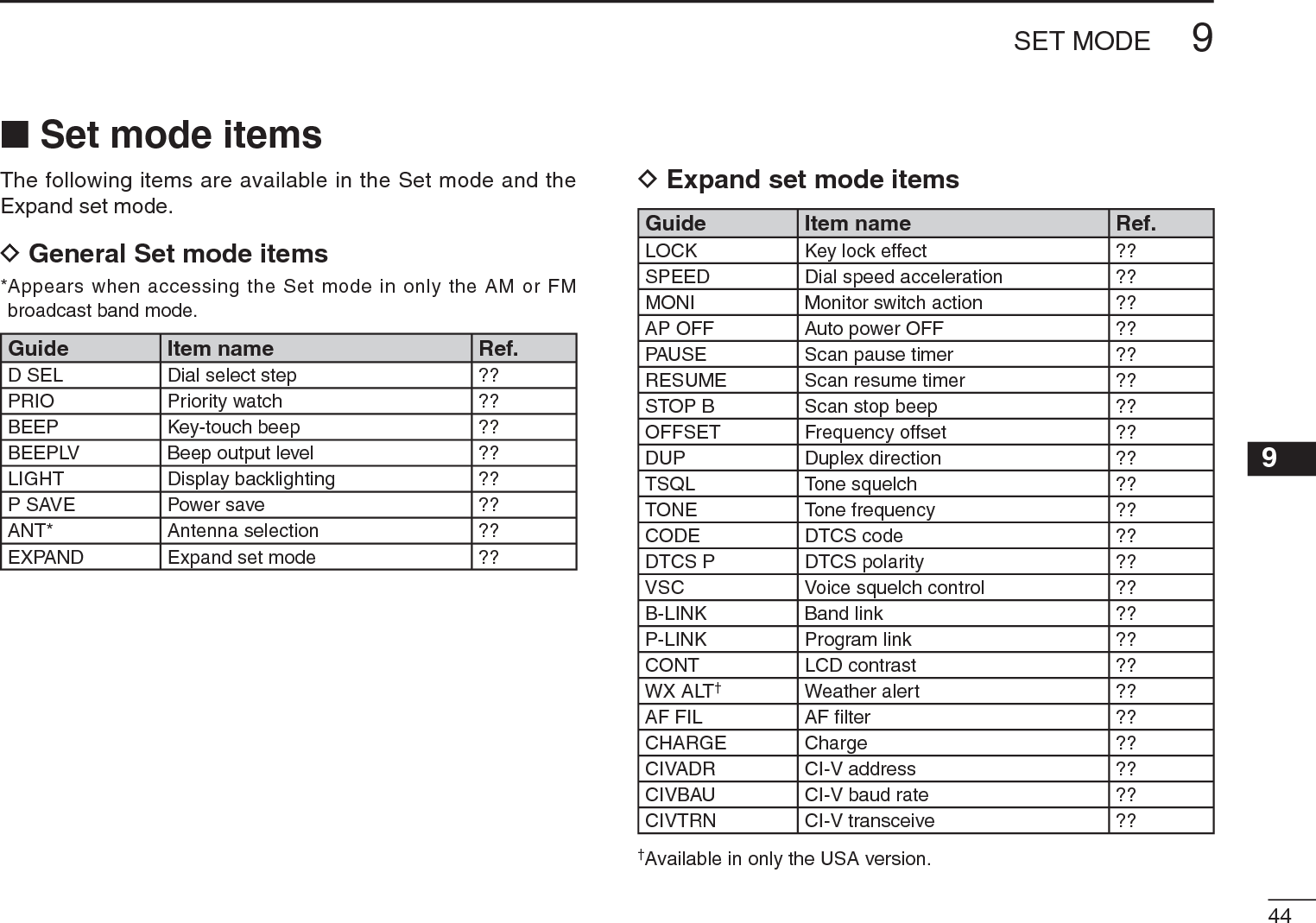
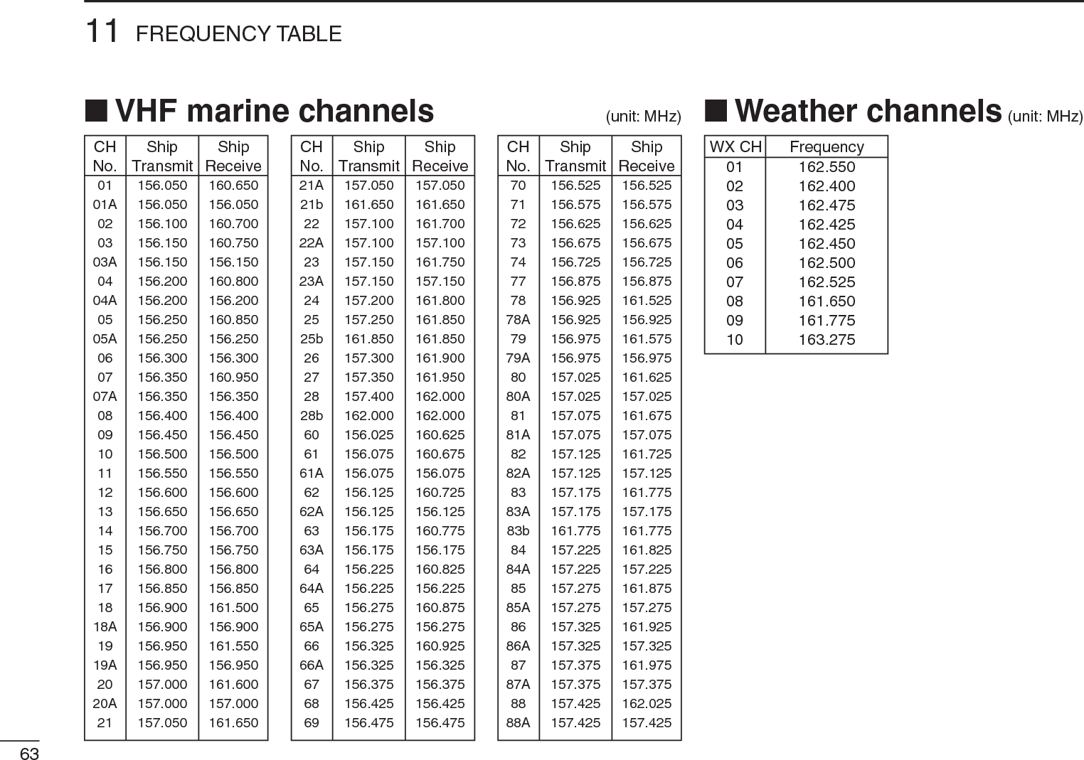
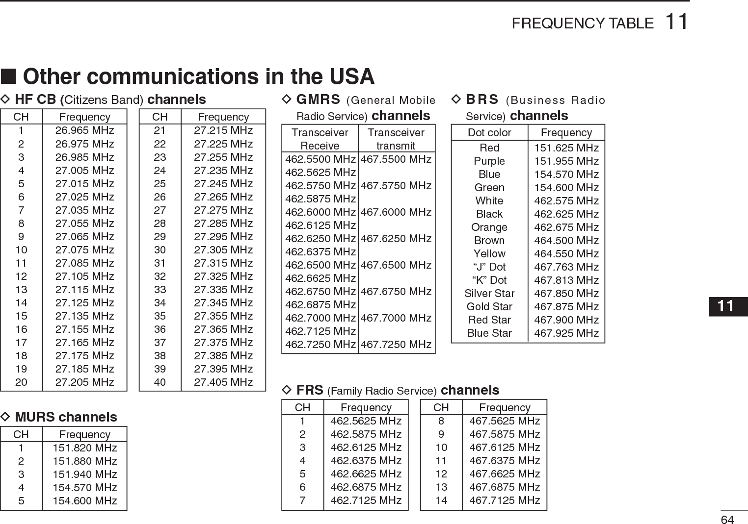
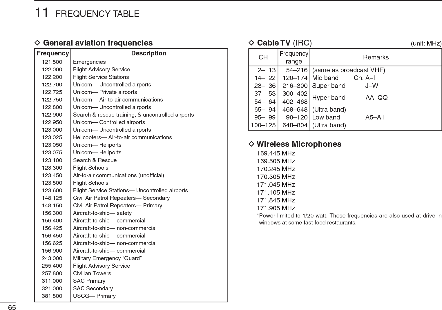
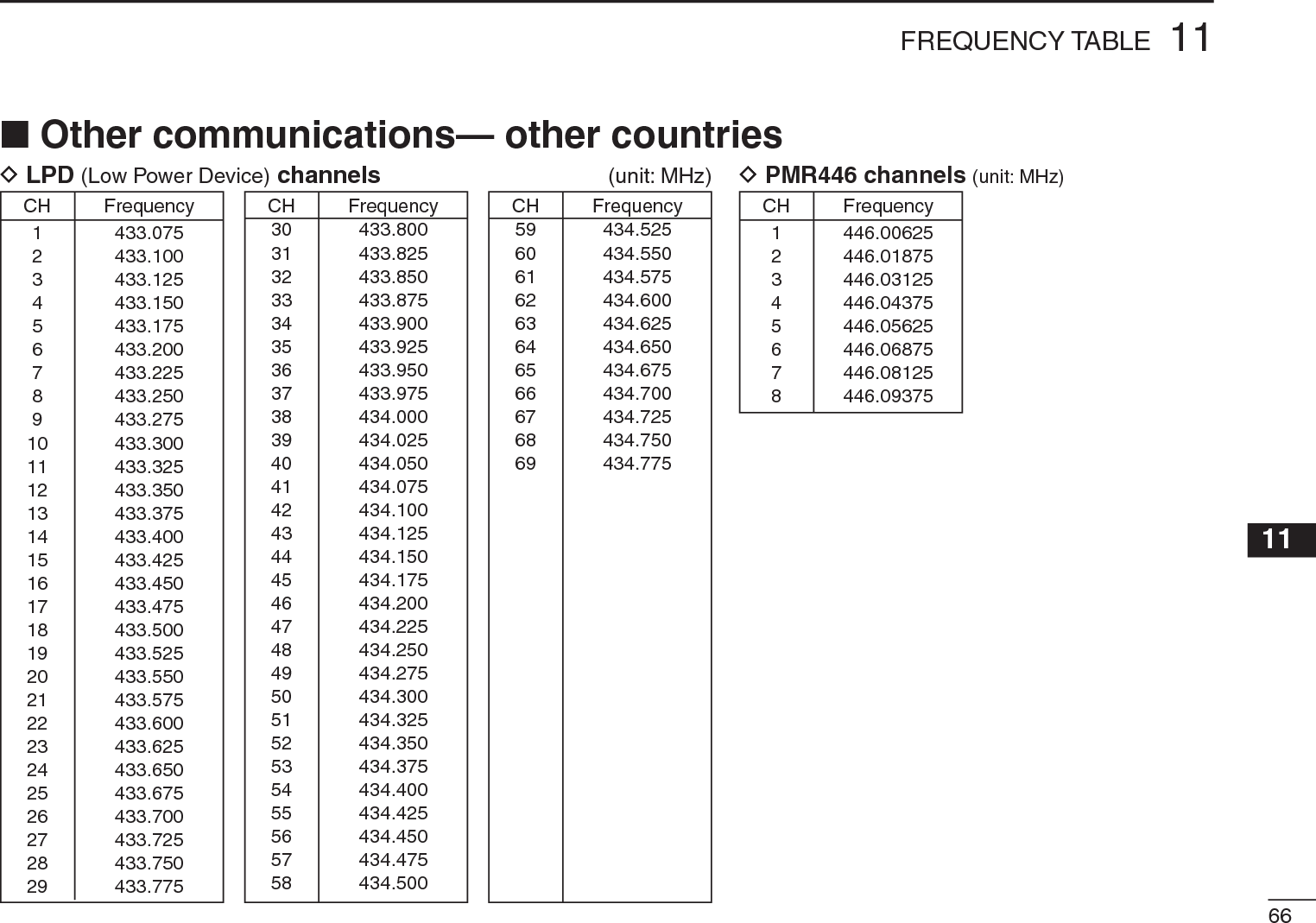
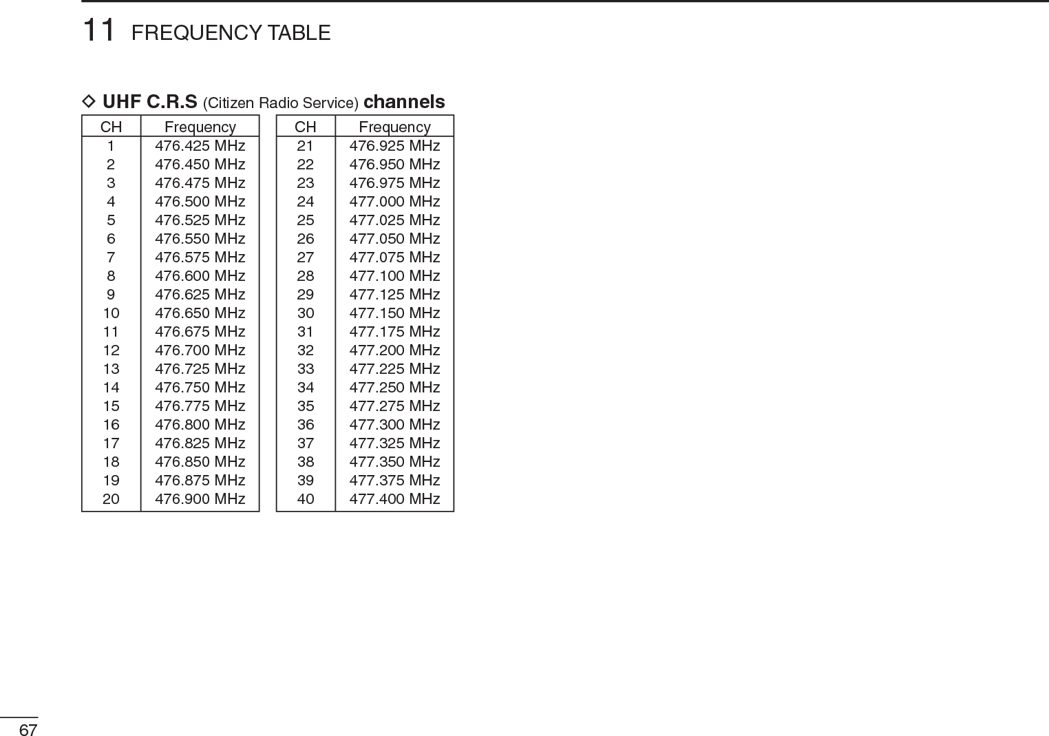
![v7 PRIORITY WATCH ……………………………… 36–38 Priority watch types…………………………………… 36 Priority watch operation ……………………………… 378 TONE SQUELCH AND POCKET BEEP ……… 39–41 Tone/DTCS squelch operation ……………………… 39Tone squelch frequency/DTCS code setting ……… 40 DTCS polarity setting ………………………………… 41 Tone scan ……………………………………………… 429 Set mode ………………………………………… 43–54 General ………………………………………………… 43 Set mode items ……………………………………… 4410 OTHER FUNCTIONS …………………………… 55–59 [DIAL] function assignment ………………………… 55 Weather channel operation ………………………… 55 Data cloning ………………………………………… 57 Auto power-off function ……………………………… 58 Partial reset …………………………………………… 59 All reset ……………………………………………… 5911 FREQUENCY TABLE …………………………… 60–67 TV channels …………………………………………… 60 VHF marine channels ………………………………… 63 Weather channels …………………………………… 63 Other communications in the USA ………………… 64Other communications— other countries ………… 6612 MAINTENANCE …………………………………… 68–69 Troubleshooting ……………………………………… 68 CP-18A/E fuse replacement ………………………… 6913 SPECIFICATIONS ……………………………………… 7014 OPTIONS ……………………………………………… 7115 POCKET GUIDE ………………………………… 72–7316 CE …………………………………………………… 73–74SUPPLIED ACCESSORIESqw eqAntenna …………………………………………………… 1wHand strap ………………………………………………… 1eBelt clip ……………………………………………………… 1TABLE OF CONTENTS](https://usermanual.wiki/ICOM-orporated/325000/User-Guide-1227030-Page-6.png)
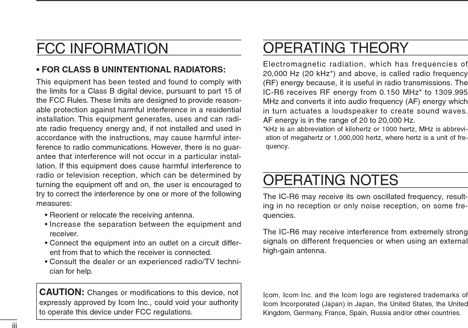
![IIQUICK REFERENCE GUIDEDCharging the batteryIC-R6CP-18A/ECigarette lighter cablewith DC-DC converterAC adapterto a cigarette lighter socketThe shape maydiffer dependingon the version.to an AC outletto the [DC4.5V]jackq Install the Ni-MH batteries.w Plug the optional AC adapter into an AC outlet.eInsert the optional adapter plug into the [DC4.5V] of the receiver.• The battery confirmation is displayed.RWARNING!:NEVER attempt to charge the alkaline batteries. t Rotate [DIAL] to select “Y,” then push [BAND].[DIAL]• The charging confirmation is displayed.uRotate [DIAL] to select “Y,” then push [BAND] to start the battery charging.Rotate Then, push• The battery icon scrolls during charge.• Both segments blink when completely charged.](https://usermanual.wiki/ICOM-orporated/325000/User-Guide-1227030-Page-8.png)
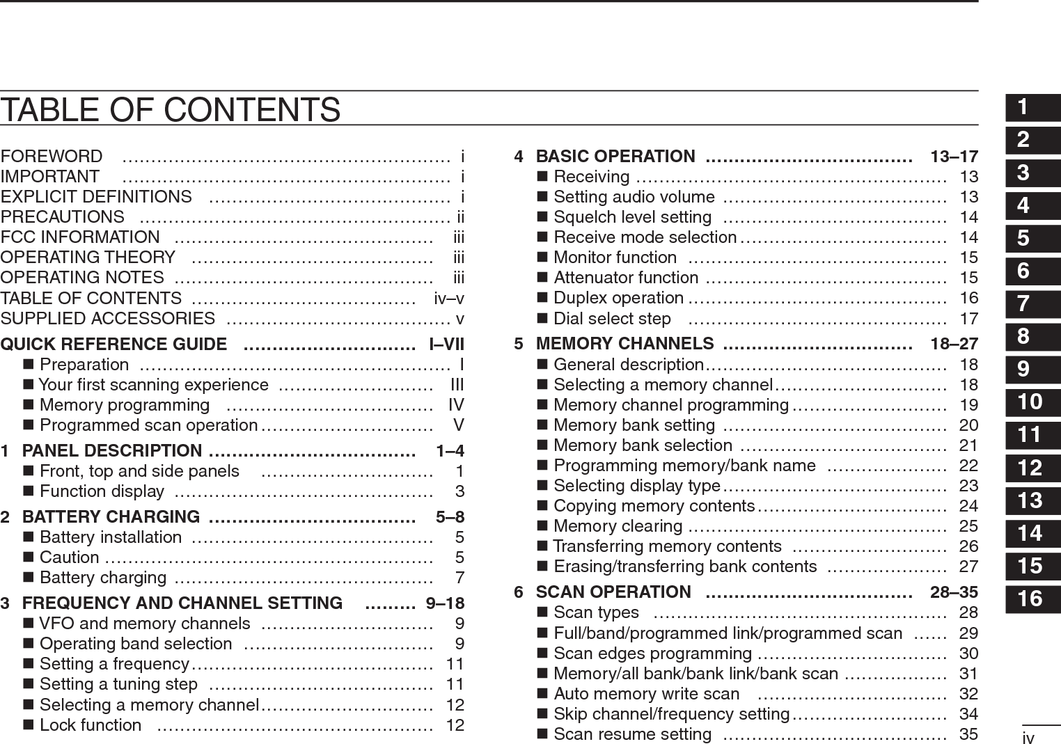
![IIIQUICK REFERENCE GUIDEQuick reference guideNow that you have your IC-R6 ready, you are probably ex-cited to start listening. We would like to take you through a few basic operation steps to make your first “Listennig Expe-rience” enjoyable. DAbout the default settingsThe [DIAL] control function can be traded with the [S]/[T]keys function in the Set mode. However, in this QUICK REF-ERENCE GUIDE, the factory default setting ([DIAL] selects the operating frequency) is used for simple instruction.DBasic operation1. Turning ON the receiver±Hold down [ ] for 1 second to turn the power ON.2. Adjusting audio level±Push [S]/[T] to set a desired audio level.3. Adjusting squelch level±While holding down [SQL],rotate [DIAL] to set the squelch level.4. Setting a desired frequencyThe tuning dial will allow you to dial in the frequency you want to listen to. Pages 9 and 15 will instruct you on how to set the tuning speed.q Push [BAND] repeatedly to select a frequency band.• Holding down [BAND], rotating [DIAL] will also select a frequency band.w Rotate [DIAL] to set the receive frequency.•While holding down [FUNC], rotate [DIAL] to select frequencies in 1 MHz steps.N Your first scanning experience[DIAL][DIAL]](https://usermanual.wiki/ICOM-orporated/325000/User-Guide-1227030-Page-9.png)
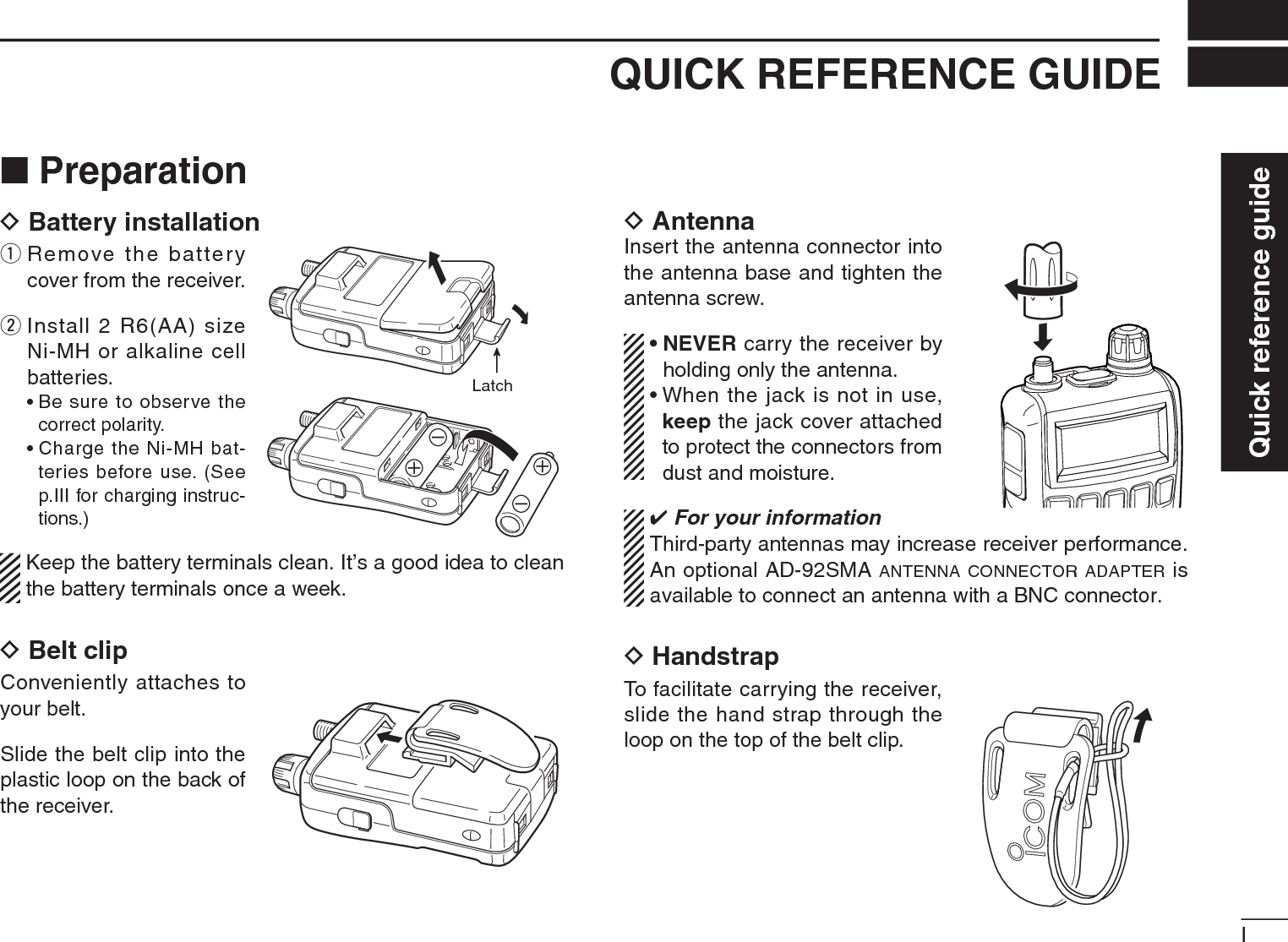
![IVQUICK REFERENCE GUIDEN Your first scanning experience (continued)5. Receive mode selection±Push [MODE] repeatedly to select a desired receive mode.• The FM, WFM or AM is selectable.N Memory programmingThe IC-R6 has a total of 1300 memory channels for stor-ing often used receive frequency, mode, etc. The memory channels include 200 auto write channels and 50 scan edge channels.1. Setting frequencyIn the VFO mode, set a desired receive frequency mode.• When the “ ” icon is displayed, push [V/M] to select the VFO mode.2. Selecting a memory channelHold down [S.MW](V/M) for 1 second, then rotate [DIAL] to select a desired memory channel.• The “ ” icon and memory chan-nel number blink.3. Writing a memory channelHold down [S.MW](V/M) for 1 second until 3 beeps sound.• The memory channel number automatically increases when hold-ing down [S.MW](V/M,) after programming.[DIAL]](https://usermanual.wiki/ICOM-orporated/325000/User-Guide-1227030-Page-10.png)
![VQUICK REFERENCE GUIDEN Programmed scan operation25 pairs, 50 channels of memories are used for programmed scan operation, that specifies a scanning ranges. The pro-grammed scan scans between “xxA” and “xxB” (xx=00 to 24) frequencies. Therefore, before operating the programmed scan, different frequencies must be programmed into “A” and “B” scan edge channels.D Programming scan edgesA start frequency must be programmed into a “xxA,” and end frequency must be programmed into a “xxB” memory chan-nel. 1. Setting frequencyIn the VFO mode, set a desired receive frequency selection mode.• When the “ ” icon is displayed, push [V/M] to select the VFO mode.2. Selecting a scan edge “A” channel Hold down [S.MW](V/M) for 1 second, then rotate [DIAL] to select one of the 25 scan edge “A” channels.• The “ ” icon and scan edge channel number blink.3. Writing a memory channelHold down [S.MW](V/M) for 1 second until 3 beeps sound.• The paired scan edge “B” channel is automatically selected when holding down [S.MW](V/M) after programming.• When programming is completed, return to the VFO mode.4. Selecting a scan edge “B” channel Hold down [S.MW](V/M) for 1 second, then rotate [DIAL] to select one of the 25 scan edge channel “B.”• The “ ” icon and the scan edge channel number blink.• When the scan edge “B” channel is already selected in step 3. (by holding down [S.MW](V/M) after programming), skip this step.5. Writing a memory channelHold down [S.MW](V/M) for 1 second until 3 beeps sound.• The next scan edge “A” channel is automatically selected when holding down [S.MW](V/M) after programming.• When programming is completed, return to the VFO mode.Quick reference guide](https://usermanual.wiki/ICOM-orporated/325000/User-Guide-1227030-Page-11.png)
![VIQUICK REFERENCE GUIDED Starting scan1. Select the VFO mode.Push [V/M] to select the VFO mode for a VFO scan opera-tion, such as full scan, band scan and programmed scan.• Select the memory mode by pushing [V/M] again for a memory scan operation, such as all memory scan, bank link scan or bank scan.2. Selecting a scan typeHold down[SCAN](MODE) for 1 second, and then rotate [DIAL]to select one of a desired scanning types.• Select “ALL” for full scan, “BAND” for band scan, “P-LINK x” for programmed link scan (x= 0 to 9), “PROGxx” for programmed scan (xx= 0 to 24; only programmed scan edge numbers are displayed).• Select “M-ALL” for all memory scan, “B-ALL” for all bank scan, “B-LINK” for bank link scan or “BANK-x” for bank scan (x= A to R, T, U, W, Y; only pro-grammed bank groups are displayed).• Full scan• Band scan• Program link scan• Program scan• All memory scan• All bank scan• Bank link scan• Bank scanScan type display examplesIn the VFO mode In the memory mode](https://usermanual.wiki/ICOM-orporated/325000/User-Guide-1227030-Page-12.png)
 to start the scan.• Rotate [DIAL] to change the scanning direction.• Full/Band scan• Program link Program scan• All memory/All bank bank link scan• Bank scanIn the VFO mode In the memory mode4. Cancelling scanPush[SCAN](MODE) again to stop the scan. For your informationThe memory channel number you program the scan edges into correlates “PROGxx” as follows:00A/00B: Selects “PROG 00” to scan between frequencies programmed in channels 00A and 00B.01A/01B: Selects “PROG 01” to scan between frequencies programmed in channels 01A and 01B. ••••23A/23B: Selects “PROG 23” to scan between frequencies programmed in channels 23A and 23B.24A/24B: Selects “PROG 24” to scan between frequencies programmed in channels 24A and 24B.Quick reference guide](https://usermanual.wiki/ICOM-orporated/325000/User-Guide-1227030-Page-13.png)
![1PANEL DESCRIPTION1N Front, top and side panels!2!0utrew!1qFunction display(pp 3, 4)SpeakeroiyqANTENNA CONNECTOR (p. I)Connect the supplied antenna.• An optional AD-92SMA is available for connecting an antenna with a BNC connector.wFUNCTION KEY [FUNC]While holding down this switch, access a key’s secondary or third function.eSQUELCH • ATTENUATOR KEY [SQL] • [ATT](SQL)±Hold down to temporarily open the squelch and moni-tor the operating frequency. (p. 13)±While holding down this switch, rotate [DIAL]* to adjust the squelch level. (p. 12)±While holding down [FUNC], push to toggle the attenu-ator function ON or OFF. (p. 10)rUP/DOWN KEYS [S]/[T]*Adjusts the audio volume level. (p. 11)t BAND • LOCK • MEMORY NAME KEY[BAND] • [ ](BAND) • [ ](BAND)± Push to select the operating frequency band. (p. 7)±While holding down [FUNC], push and hold for 1 second to toggle the lock function ON or OFF. (p. 10)±During memory mode operation, hold down [FUNC],then push this key to select the display type.• The display shows the memory bank name†, memory name†and channel number in sequence, and then returns to the frequency display.†The memory bank name or memory name must have pre-programmed.*The functions of [DIAL] and [S]/[T] can be exchanged. See page 49 for details.](https://usermanual.wiki/ICOM-orporated/325000/User-Guide-1227030-Page-14.png)
![21PANEL DESCRIPTION12345678910111213141516y TUNING STEP • SET • DIAL EXCHANGE KEY[TS] • [SET](TS) • [ ](TS)]± Push to enter tuning step selecting mode. (p. 9)± Hold down for 1 second to enter the Set mode. (p. 39)±While holding down [FUNC], push to exchange the [DIAL] and [S]/[T] keys’ functions. (p. 49)uPOWER KEY [ ]Hold down for 1 second to turn the receiver power ON or OFF.i MODE • SCAN • TONE SCAN KEY [MODE] • [SCAN](MODE) • [ ](MODE)± Push to select the receive mode. (p. 12)±Hold down for 1 second to enter the scan type selec-tion mode. (p. 26)• Push again to start the scan.±While holding down [FUNC], push to start a tone scan. (p. 38)o VFO/MEMORY • MEMORY WRITE • SKIP KEY[V/M] • [S.MW](V/M) • [ ](V/M)± Toggles between the VFO or the memory mode. (p. 7)±Hold down for 1 second to enter memory edit condi-tion. (p. 16)±During VFO mode operation, hold down [FUNC], then push this key to select the programmed skip scan set-ting ON or OFF. ±During memory mode operation, hold down [FUNC],then push this key to select the scan skip condition for the selected channel. (p. 30)!0EXTERNAL DC-IN CONNECTOR [DC4.5V] (p. 6)Connects an AC adapter or an optional cigarette lighter cable for both charging the installed re-chargeable battery and operating. Connectable voltage is from 4.5 V DC to 6.3 V DC.!1EXTERNAL SPEAKER CONNECTOR [SP]Connect an optional earphone or headphones.The internal speaker will not function when any external equipment is connected. (See page 65 for a list of avail-able options.)!2CONTROL DIAL [DIAL]*± Rotate to select the operating frequency.* (p. 9)±While scanning, changes the scanning direction. (p. 26)±While holding down [SQL], sets the squelch level. (p. 12)±While holding down [FUNC], sets the operating fre-quency in 100 kHz, 1 MHz or 10 MHz in the VFO mode. (p. 9)±While holding down [FUNC], selects the memory chan-nel in 10 channels steps in the memory mode. (p. 10)±While holding down [BAND], selects the operating band in the VFO mode. (p. 7)*The functions of [DIAL] and [S]/[T] can be exchanged. See page 49 for details.](https://usermanual.wiki/ICOM-orporated/325000/User-Guide-1227030-Page-15.png)
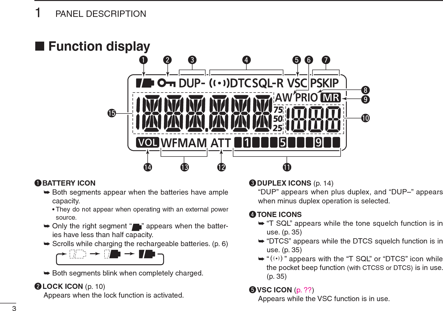
![41PANEL DESCRIPTION1yAUTO WRITE CHANNEL ICON (p. 29)Appears when an auto write channel is selected.uSKIP ICONS (p. 30)±“SKIP” appears when the selected memory channel is specified as a skip channel.±“PSKIP” appears when the displayed frequency is specified as a skip frequency.iPRIORITY WATCH ICON (p. 33)Appears while priority watch is in use.oMEMORY ICON (pgs. 7, 10)Appears when the memory mode is selected.!0MEMORY CHANNEL NUMBERShows the selected memory channel number. (pgs. 7, 10)!1SIGNAL STRENGTH INDICATOR (p. 11)Shows the relative signal strength while receiving signals. !2ATTENUATOR ICON (p. 13)Appears while the RF attenuator is in use.!3RECEIVE MODE ICON (p. 12)Shows the selected receive mode.• FM, WFM and AM modes are selectable.!4VOLUME EXCHANGE ICON (p. 49)Appears when the function of [DIAL] and [S]/[T] are exchanged.!5FREQUENCY READOUT Shows a variety of information, such as the operating fre-quency, Set mode contents, memory names.• The smaller “75,” “50” and “25” to the right of the readout indi-cate 0.75, 0.5 and 0.25 kHz, respectively.• The decimal point blinks during a scan.](https://usermanual.wiki/ICOM-orporated/325000/User-Guide-1227030-Page-17.png)
![5BATTERY CHARGING2N Battery installationBefore installing, or replacing the batteries, hold down [ ]for 1 second to turn the power OFF.q Remove the battery cover from the receiver.Latchw Install 2 R6 (AA) size Ni-MH batteries.• Be sure to observe the correct polarity.N Caution•R DANGER! NEVER short the battery terminals (or charg-ing terminals). Also, current may flow into nearby metal objects such as a necklace, so be careful when placing batteries (or the receiver) in handbags, etc.Simply carrying with or placing near metal objects such as a necklace, etc. may cause shorting. This may damage not only the batteries, but also the receiver.•R DANGER! NEVER incinerate used batteries. Internal battery gas may cause an explosion.•R DANGER! NEVER immerse the batteries in water. If the batteries become wet, be sure to wipe them dry BEFOREinstalling them to the receiver.• When installing batteries, make sure they are all the same brand, type and capacity. Also, do not mix new and old bat-teries together.• Never use batteries whose insulated covering is damaged.•Keep battery terminals clean to avoid rust or misscontact. It’s a good idea to clean battery terminals once a week.D Caution for the Ni-MH batteries•CAUTION: Always use the batteries within the speci-fied temperature range, –5˚C to +60˚C (+23˚F to +140˚F). Using the batteries out of their specified temperature range will reduce the battery’s performance and battery life.](https://usermanual.wiki/ICOM-orporated/325000/User-Guide-1227030-Page-18.png)
![72BATTERY CHARGINGN Battery chargingD Charging connectionsIC-R6CP-18A/ECigarette lighter cablewith DC-DC converterAC adapterto a cigarette lighter socketThe shape maydiffer dependingon the version.to an AC outletto the [DC4.5V]jack• Charging periods: Approx. 15 hoursRWARNING!:NEVER attempt to charge the alkaline batteries. CAUTION: BE SURE to disconnect the CP-18A/E from the cigarette lighter socket when charging is finished, be-cause, a slight current still follows in the CP-18A/E and the vehicle’s battery will become exhausted.D Charging descriptionqInstall the Ni-MH batteries. (See page 5.)w Plug the AC adapter into an AC outlet; or the CP-18A/E into a cigarette lighter socket.eInsert the adapter plug into [DC4.5V] of the receiver.• Once the batteries are removed for more then 2 seconds, the following operations are necessary.• The battery confirmation is displayed.If the confirmation does not appear, following operation is necessary.q Disconnect the adapter plug from [DC4.5V].w Holding down [FUNC], insert the adapter plug again.e Release [FUNC].r Rotate [DIAL] to select “Y,” then push [BAND].[DIAL]](https://usermanual.wiki/ICOM-orporated/325000/User-Guide-1227030-Page-20.png)
![82BATTERY CHARGING12345678910111213141516• The charging confirmation is displayed.uRotate [DIAL] to select “Y,” then push [BAND] to start the battery charging.Rotate Then, push• The battery icon scrolls during charge.• Both segments blink when completely charged.• It takes approximately 13 hours to fully charge the Ni-MH bat-teries.D Charge adapter BC-194The BC-194, charge adapter, is useful to charge, and the receiver is easy to attach to or detach from the BC-194.The BC-194 can be used the BC-196S/BC-153SC or CP-18A/E to a power source.ReceiverBC-194CP-18A/Ecigarette lighter cableAC adapter(supplie with receiver)Double-sided tape(with BC-194)Ground screw(with BC-194)](https://usermanual.wiki/ICOM-orporated/325000/User-Guide-1227030-Page-21.png)
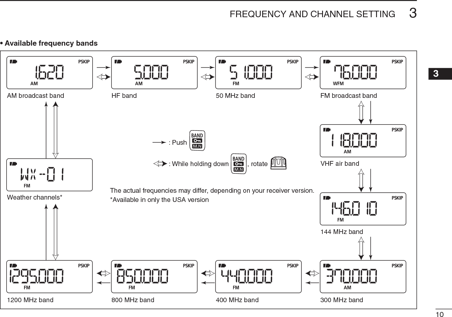
![9FREQUENCY AND CHANNEL SETTING3N VFO and memory channelsThe IC-R6 has 2 normal operating modes: the VFO mode and the memory mode.The VFO mode is used for a desired frequency setting within the frequency coverage.± Push [V/M] to select the VFO mode.The memory mode is used for quick recall the preprogrammed memory channels.± Push [V/M] to select the memory mode.• See p. 16 for memory programming details.[DIAL]“ ” and memory channel number appear.• VFO mode display• Memory mode displayWhat is VFO?VFO is an abbreviation of Variable Frequency Oscillator. Operating frequencies are generated and controlled by the VFO.N Operating band selectionThe receiver can receive the AM broadcast, HF band, 50 MHz, FM broadcast, VHF air, 144 MHz, 300 MHz, 400 MHz, 800 MHz,* 1200 MHz, television channels or Weather channels†.±Push [BAND] repeatedly to select a desired frequency band.• When the memory mode is selected, push [V/M] to select the VFO mode first, then push [BAND] to select a desired band.±While holding down [BAND], rotating [DIAL] also selects frequency band.[DIAL]Available frequency bands are differ depending on ver-sion. See the specification for details. *Some frequency ranges are inhibited for the USA version due to local regulation.†Available in only the USA version.](https://usermanual.wiki/ICOM-orporated/325000/User-Guide-1227030-Page-22.png)
![113FREQUENCY AND CHANNEL SETTING N Setting a frequencyqPush [V/M] to select the VFO mode, if necessary.wSelect a desired frequency band with [BAND].• Or, while holding down [BAND], rotate the [DIAL] to select a desired frequency band.eRotate [DIAL] to select a desired frequency band.• The frequency changes according to the preset tuning steps. See the section to the right for setting the tuning step.• While holding down [FUNC], rotate [DIAL] to change the fre-quency in 1 MHz steps (default).[DIAL][DIAL] changes thefrequency according tothe selected tuning step.While continuing to push[FUNC], [DIAL] changesthe frequency in 1 MHzsteps (default).The 1 MHz tuning step (dial select step) can be set to 100 kHz, 1 MHz or 10 MHz tuning steps in the Set mode. See p. 15 for details.NSetting a tuning stepThe tuning step can be selected for each frequency band. However, additional steps become selectable only in theadditional steps become selectable only in the VHF Air band (8.33 kHz) and in the AM broadcast band (9 kHz)*. The following tuning steps are available for the IC-R6.The following tuning steps are available for the IC-R6.• 5.0 kHz • 6.25 kHz • 8.33 kHz* • 9.0 kHz*• 10.0 kHz • 12.5 kHz • 15.0 kHz • 20.0 kHz• 25.0 kHz • 30.0 kHz • 50.0 kHz • 100.0 kHzD Tuning step selectionqPush [V/M] to select the VFO mode, if necessary.wPush [BAND] to select a desired frequency band.• Or, while holding down [BAND], rotate [DIAL] to select a desired frequency band.ePush [TS] to enter tuning step selecting condition.rRotate [DIAL] to select a desired tuning step.tPush [TS] to return to the VFO mode.[DIAL]5 kHz tuning step](https://usermanual.wiki/ICOM-orporated/325000/User-Guide-1227030-Page-24.png)
![123FREQUENCY AND CHANNEL SETTING 3N Selecting a memory channelqPush [V/M] to select the memory mode.• “ ” appears when the memory mode is selected.wRotate [DIAL] to select a desired memory channel.• Only programmed memory channels can be selected.• While holding down [FUNC], rotate [DIAL] to select a memory channel in 10 channels steps.[DIAL][DIAL] changes thememory channel.N Lock functionTo prevent accidental frequency changes and unnecessary function access, use the lock function. ±While holding down [FUNC], push and hold [ ](BAND)for 1 second to turn the lock function ON or OFF.• “ ” appears while the lock function is activated.•[SQL] and [S]/[T] can be used while the lock function is in use with default setting. Either or both [SQL] and [S]/[T] keys can also be locked in the Set mode. (p. 43)“ ” appears while the lock function is in use.](https://usermanual.wiki/ICOM-orporated/325000/User-Guide-1227030-Page-25.png)
![13BASIC OPERATION4N ReceivingMake sure charged Ni-MH or brand new alkaline batteries are installed (p. 5).qHold down [] for 1 second to turn power ON.wPush[S] or [T] to set a desired audio level. • The function display shows the volume level while setting. See the section to the right for details.eSet the receive frequency. (p. 9)rSet the squelch level. (p. 12)• While holding down [SQL], rotate [DIAL].• The first click of [DIAL] indicates the current squelch level.• “LEVEL 1” is loose squelch and “LEVEL 9” is tight squelch.• “AUTO” indicates automatic level adjustment with a noise pulse count system.• Hold down [SQL] to open the squelch manually.t When a signal is received:• Squelch opens and audio is heard.• The S-meter shows the relative signal strength.qPower ON [ ]e Set frequencyr Set squelch levelw Set audio levele Select bandr Push for settingthe squelch(Push to monitor)NSetting audio volumeThe audio level can be adjusted through 40 levels.±Push [S] or [T] to adjust the audio level. • A beep tone sounds while adjusting. The tone sound let you know the approximate sound level.• Holding down either key will continuously change the audio level.• The display shows the volume level while setting.AUDIO LEVELMinimum level(no audio)Maximum levelInitial settingDISPLAY](https://usermanual.wiki/ICOM-orporated/325000/User-Guide-1227030-Page-26.png)
![144BASIC OPERATION4N Squelch level settingThe squelch circuit mutes the received audio signal, depend-ing on the signal strength. The receiver has 9 squelch levels, a continuously open setting and an automatic squelch set-ting.±While holding down [SQL], rotate [DIAL] to select the squelch level.• “LEVEL 1” is loose squelch (for weak signals) and “LEVEL 9” is tight squelch (for strong signals).• “AUTO” indicates the automatic level adjustment by a noise pulse count system.• “OPEN” indicates the continuously open setting.[DIAL]Automatic squelchMaximum levelN Receive mode selectionThe receiver has three receive modes, FM, AM and WFM. The mode selection is stored independently in each band and memory channels.Typically, the AM mode is used for the AM broadcast stations (0.495–1.620 MHz) and air band (118–135.995 MHz), and WFM is used for FM broadcast stations (76–107.9 MHz).±Push [MODE] repeatedly to select a desired receive mode.FM modeAM modeWFM mode](https://usermanual.wiki/ICOM-orporated/325000/User-Guide-1227030-Page-27.png)
![N Monitor functionThis function is used to listen to weak signals, without dis-turbing the squelch setting. It can also be used to open the squelch manually, even when mute functions such as the tone squelch are in use.± Hold down [SQL] to monitor the receive frequency.• The 1st segment of the S-meter blinks.The 1st/2nd segments blinkThe [SQL] switch can be set to a ‘sticky’ operation in the Expand set mode. See page 43 for details.N Attenuator functionThe attenuator prevents a received signal from distorting when very strong signals are near a desired frequency, or when very strong electric fields, such as from a broadcasting station, are near your location.± While holding down [FUNC], push [ATT](SQL) to toggle the attenuator function ON or OFF.• “ATT” appears when the attenuator functions is in use.“ATT” appears while theattenuator functions is inuse.154BASIC OPERATION](https://usermanual.wiki/ICOM-orporated/325000/User-Guide-1227030-Page-28.png)
 for 1 second to enter the Set mode.eRotate [DIAL] to select the “EXPAND” item.• “EXPAND” disappears after 1 second and “OFF” (default) and “EX” appear.[DIAL]Expanded set mode itemSetting displayr While holding down [FUNC], rotate [DIAL] to select “ON.”tRotate [DIAL] to select the “OFFSET” item.• “OFFSET” disappears after 1 second and “0.600” (default) and “OW” appear. (Default offset differs depending on the frequency band or receiver version.)Frequency offset item Setting displayAfter 1 sec.y While holding down [FUNC], rotate [DIAL] to set a desired offset frequency within 0.000–159.995 MHz range.• The tuning step, selected in the VFO mode, is used for setting.uRotate [DIAL] to select the “DUP” item.• “DUP” disappears after 1 second and “OFF” (default) and “DP” appear.Duplex item Setting indicationAfter 1 sec.i While holding down [FUNC], rotate [DIAL] to select “–DUP” or “+DUP.”oPush [SET](TS) to exit the Set mode.!0 Hold down [SQL] to monitor the transmit station frequen-cy (repeater input frequency) directly.NDuplex operation USING EXPAND SET MODE](https://usermanual.wiki/ICOM-orporated/325000/User-Guide-1227030-Page-29.png)
![174BASIC OPERATIONN Dial select step [This receiver has a 1 MHz tuning step for quick frequency setting. You can select 100 kHz, 1 MHz or 10 MHz steps, as desired.D Setting dial select stepqPush [V/M] to select the VFO mode.wHold down [SET](TS) for 1 second to enter the Set mode.eRotate [DIAL] to select the “D SEL” item.• “D SEL” disappears after 1 second and “1M” (default) and “DS” appear.r While holding down [FUNC], rotate [DIAL] to select a desired dial select step.• 100 kHz, 1 MHz and 10 MHz can be selected.tPush [SET](TS) to exit the Set mode.[DIAL]1 MHz step10 MHz step100 kHz step](https://usermanual.wiki/ICOM-orporated/325000/User-Guide-1227030-Page-30.png)
![185MEMORY CHANNELS45N General descriptionThe receiver has 1350 memory channels, including 50 scan edge memory channels (25 pairs) for storage of often-used frequencies. A total of 18 memory banks, A to R, T, U, W and Y can be selected. Up to 100 channels can be assigned to each bank.D Memory channel contentsThe following information can be programmed into memory channels:• Receive frequency (p. 9)• Receive mode (p. 12)• Duplex direction (+DUP or –DUP) with a frequency offset (p. 14)• Tone squelch or DTCS squelch ON/OFF (p. 35)• Tone squelch frequency or DTCS code with polarity (pp. 36, 37)• Scan skip setting (p. 30)• Memory bank (p. 95)• Memory name (p. 97)• Tuning step (p. 22)N Selecting a memory channelq Push [V/M] to select the memory mode.• Push [V/M] to toggle between the VFO mode and the memory channel mode.w Rotate [DIAL] to select a desired memory channel.• Only programmed channels are displayed.• While holding down [FUNC], rotate [DIAL] to select the memory channel in 10 channel steps.AppearsRotate [DIAL] to selectthe memory channel.NOTE: Memory data can be erased by static electricity, electric transients, etc.In addition, it can be erased by malfunction and during repairs. Therefore, we recommend that memory data be written down or saved to a PC using the CS-R6 CLONINGSOFTWARE.](https://usermanual.wiki/ICOM-orporated/325000/User-Guide-1227030-Page-31.png)
![195MEMORY CHANNELSNMemory channel programmingqPush [V/M] to select the VFO mode.wSet a desired frequency:± Select a desired band with [BAND].± Set a desired frequency with [DIAL].±Set other data (e.g. frequency offset, duplex direction, tone squelch, etc.), if desired.e Hold down [S.MW](V/M) for 1 second to enter the select memory write mode.• 1 short and 1 long beep sound.• The “ ” icon and memory channel number blink.rRotate [DIAL] to select a desired channel.• Scan edge channels, 00A/B to 24A/B can also be selected.• While holding down [FUNC], rotate [DIAL] to select memory channels in 10 channel steps.tHold down [S.MW](V/M) for 1 second.• 3 beeps sound• The memory channel number automatically increases when holding down [S.MW](V/M) after programming.NOTE: Push [V/M] to cancel programming and exit the select memory write mode, before memory programming is finished.RotateHold down for 1 sec. to select channel 20.Hold down for 1 sec. to program.The VFO mode Enter the select memory write mode.Return to the VFO mode.[EXAMPLE]: Programming 145.870 MHz into memory channel 20 (a blank channel).](https://usermanual.wiki/ICOM-orporated/325000/User-Guide-1227030-Page-32.png)
 for 1 second to enter the select memory write mode.• 1 short and 1 long beep sound.• The “ ” icon and memory channel number blink.wRotate [DIAL] to select a desired memory channel.e While holding down [MODE], rotate [DIAL] to select the “BANK” item.• The bank group and channel number are displayed if the select-ed memory channel has already been assigned to a bank.• The “BANK” item can also be selected by pushing [MODE]repeatedly.[DIAL]Afterreleased.• After releasing [MODE], “-- -- -- --” is displayed instead of the frequency display, and only the “ ” icon blinks.r While holding down [BAND], rotate [DIAL] to select a desired bank group.• Bank groups A to R, T, U, W and Y are available.• The bank groups can also be selected by repeatedly pushing [BAND].[DIAL]Bank grouptRotate [DIAL] to select a desired bank channel number.• Only vacant bank channel numbers are displayed.[DIAL]Bank channely Hold down [S.MW](V/M) for 1 second to assign the chan-nel to the bank.• Return to the previous screen before entering the select memo-ry write mode.](https://usermanual.wiki/ICOM-orporated/325000/User-Guide-1227030-Page-33.png)
![215MEMORY CHANNELSN Memory bank selectionqPush [V/M] to select the memory mode.w While holding down [BAND], rotate [DIAL] to select a desired bank.• The bank can also be selected by pushing [BAND] repeatedly.• Only banks with entries are displayed.[DIAL]Auto write channelsRegular memorychannelsOnly banks with entries are displayede Rotate [DIAL] to select the bank channel.• Only programmed channels are displayed.[DIAL] Bank initialBank chanel numberr To return to a regular memory channel, rotate [DIAL]while holding down [BAND], or repeatedly push [BAND].](https://usermanual.wiki/ICOM-orporated/325000/User-Guide-1227030-Page-34.png)
![225MEMORY CHANNELS5Each memory channel can be programmed with an alpha-numeric channel name for easy recognition, and can be dis-played independently by channel. Names can be a maximum of 6 characters.qPush [V/M] to select the memory mode.wRotate [DIAL] to select a desired memory channel.e Hold down [S.MW](V/M) for 1 second to enter the select memory write mode.• 1 short and 1 long beep sound.• The “ ” icon and memory channel number blink.r While holding down [MODE], rotate [DIAL] to select the “M NAME” or “B NAME” item when programming the memory name or the bank name, respectively.• The item can also be selected by pushing [MODE] repeatedly.Bank name selectionMemory name selection• After releasing [MODE], a line blinks under the first digit, and the “ ” icon blinks.t While holding down [FUNC], rotate [DIAL] to select a desired character.• The selected character blinks.yRotate [DIAL] to move the cursor to the left or to the right.Bank nameMemory nameu Repeat steps t and y until a desired 6-character chan-nel name is displayed.i Push [MODE] repeatedly, or rotate [DIAL] while holding down [MODE] to select the “S.MW” item. o Hold down [S.MW](V/M) for 1 second to program the name and exit the programming mode.• 3 beeps sound.• Available charactersA to Z, 0 to 9, ( , ) , , +, –, , /, |, = and space.NOTE: Only one bank name can be programmed into each bank. Therefore, the previously programmed bank name will be displayed when bank name is selected. Also, the programmed bank name is automatically assigned to another bank channel.N Programming memory/bank name](https://usermanual.wiki/ICOM-orporated/325000/User-Guide-1227030-Page-35.png)
![235MEMORY CHANNELSN Selecting display typeDuring memory mode operation, either the programmed bank name, memory name or the channel number can be displayed instead of the frequency display.[DIAL]Frequency displayBank name displayMemory name displayChannel number displayqPush [V/M] to select the memory mode.• If desired, push [BAND] repeatedly to select a desired bank group.w While holding down [FUNC], push [BAND] repeatedly to select the display type from frequency, bank name, mem-ory name or the channel number.D Selecting bank channel displayDuring bank channel operation, the bank channel number can also be displayed, instead of the memory channel number.qSelect the channel number display as described to the left.w While holding down [BAND], rotate [DIAL] to select a desired bank.• The bank can also be selected by pushing [BAND] repeatedly.PushMemory channel number displayBank channel number displayBank channel number displayAuto write channel number displayWhen the selected memory channel has no programmed the bank name or memory name, the frequency is displayed.](https://usermanual.wiki/ICOM-orporated/325000/User-Guide-1227030-Page-36.png)
![245MEMORY CHANNELS5NCopying memory contentsThis function transfers a memory channel’s contents to the VFO (or another memory channel). This is useful when search-ing for signals around a memory channel frequency and for recalling the frequency offset, subaudible tone frequency etc.DMemoryDVFOqSelect the memory channel to be copied.±Push [V/M] to select the memory mode, then rotate [DIAL] to select a desired channel.• If desired, push [BAND] repeatedly to select a desired bank group, then rotate [DIAL] to select a desired bank channel.w Hold down [S.MW](V/M) for 1 second to enter the select memory write mode.• 1 short and 1 long beep sound.• The “ ” icon and memory channel number blink.eRotate [DIAL] to select “VF.” r Hold down [S.MW](V/M) for 1 second to write the selected channel contents into the VFO.• Automatically returns to the VFO mode.Holding down [S.MW](V/M) for 2 seconds in step w will also copy the memory contents to the VFO. In that case, steps e and r are not necessary.DMemoryDmemoryqSelect the memory channel to be copied.±Push [V/M]to select the memory mode, then rotate [DIAL] to select a desired channel.w Hold down [S.MW](V/M) for 1 second to enter the select memory write mode.• 1 short and 1 long beep sound.• The “ ” icon and memory channel number blink.• Do not hold down [S.MW](V/M) for more than 2 seconds. Otherwise the memory contents will be copied to the VFO.eRotate [DIAL] to select the target memory channel.r Hold down [S.MW](V/M) for 1 second again to copy.Rotate .Hold down for 1 sec. Hold down for 1 sec. to program.Select the memory channel[EXAMPLE]: Copying channel 20 to 51.](https://usermanual.wiki/ICOM-orporated/325000/User-Guide-1227030-Page-37.png)
 for 1 second to enter the select memory write mode.• 1 short and 1 long beep sounds.• The “ ” icon and memory channel number blink.• Do not hold down [S.MW](V/M) for more than 2 seconds. Otherwise the memory contents will be copied to the VFO.w Rotate [DIAL] to select a desired memory channel to be cleared.e While holding down [MODE], rotate [DIAL] to select the “CLEAR” item.• The “CLEAR” item can also be selected by pushing [MODE]repeatedly.[DIAL]Afterreleased.• After releasing [MODE], “CLR” is displayed and the “ ” icon blinks.r Hold down [S.MW](V/M) for 1 second to clear the con-tents.• 3 beeps sound.• The cleared channel changes to a blank channel.• Return to the select memory write mode.— The “ ” icon and memory channel number blink. Push and hold for 1 sec.t Push [V/M] to return to the screen displayed before you the select memory write mode in step q.After step w, while holding down [FUNC], push and hold [S.MW] (V/M) for 1 second can also be clear the con-tents. In that case, steps e and r are not necessary.BE CAREFUL!— The contents of cleared memories CANNOT be recalled, even in the bank channel mode.](https://usermanual.wiki/ICOM-orporated/325000/User-Guide-1227030-Page-38.png)
 for 1 second to enter the select memory write mode.• 1 short and 1 long beep sounds.• The “ ” icon and memory channel number blink.• Do not hold down [S.MW](V/M) for more than 2 seconds. Otherwise the memory contents will be copied to the VFO.w Rotate [DIAL] to select a desired memory channel to be transferred.e While holding down [MODE], rotate [DIAL] to select the “CLEAR” item, then release [MODE].• Pushing [MODE] repeatedly also selects the “CLEAR” item.rHold down [S.MW](V/M) for 1 second. • The displayed contents are cleared.CONVENIENT!:Instead of doing steps e and r, while holding down [FUNC], push and hold [S.MW](V/M) for 1 second also clears the contents.tRotate [DIAL] to select a desired target memory channel.y Hold down [S.MW](V/M) for 1 second to transfer the con-tents.[DIAL]• ExampleTransferring the contents of memory channel 51 to channel 33.Steps q and wStep eStep rStep tStep y](https://usermanual.wiki/ICOM-orporated/325000/User-Guide-1227030-Page-39.png)
![275MEMORY CHANNELSThe contents of programmed memory channels can be erased or transferred to another memory.INFORMATION: Even if the memory bank contents are erased, the memory channel contents still remain pro-grammed.q Select a desired bank contents to be transferred or erased from the bank.± Push [V/M] to select the memory mode.±While holding down [BAND], rotate [DIAL] to select a desired memory bank group.± Rotate [DIAL] to select the bank channel.w Hold down [S.MW](V/M) for 1 second to enter the select memory write mode.• 1 short and 1 long beep sounds.• Do not hold down [S.MW](V/M) for more than 2 seconds. Otherwise the bank contents will be copied to the VFO.Push and hold for 1 sec.• The original memory channel number is automatically dis-played, then the “ ” icon and the memory channel number blink.e While holding down [MODE], rotate [DIAL] to select the “BANK” item.• Pushing [MODE] repeatedly also selects the “BANK” item.r While holding down [BAND], rotate [DIAL] to select a desired bank group to transfer.• Select the “-- -- -- --” display when erasing the contents from the bank.[DIAL] To transfer the bank contentsin bank E.To erasetRotate [DIAL] to select a desired bank channel.y While holding down [MODE], rotate [DIAL] to select the “S.MW” item.• Pushing [MODE] repeatedly also selects the “S.MW” item.u Hold down [S.MW](V/M) for 1 second to erase or transfer the bank contents.N Erasing/transferring bank contents](https://usermanual.wiki/ICOM-orporated/325000/User-Guide-1227030-Page-40.png)
![286SCAN OPERATION12345678910111213141516N Scan typesScanning automatically searches for signals and makes it easier to locate new stations for listening purposes.There are 7 scan types and 4 resume options to suit your operating needs.FULL SCAN (p. 26)100kHz1309.995MHzScanJumpRepeatedly scans all frequen-cies over the entire band.Some frequency ranges are not scanned, depending on the frequency coverage of the receiver version.SELECTED BAND SCAN (p. 26)BandedgeBandedgeScanJumpRepeatedly scans all fre-quencies over the entire selected band. ALL/SELECTED BANK SCAN (p. 28)SKIPSKIPA99 A03A00 A01 A02A04A98A05Repeatedly scans all bank channels or selected bank channels. The skip scan is also selectable.FREQUENCY/MEMORY SKIP FUNCTION (p. 30)BandedgeBandedgeScanSKIP SKIPJumpSkips unwanted frequencies or channels that inconven-iently stop scanning. This function can be turned ON or OFF by pushing [FUNC] + [ ](V/M) in either the VFO or the memory mode.PROGRAMMED SCAN (p. 26)Bandedge xxA xxBBandedgeScan edgesScanJumpRepeatedly scans between two user-programmed fre-quencies. Used to check for frequencies within a specified range, such as repeater out-put frequencies, etc.MEMORY (SKIP) SCAN (p. 28)SKIPSKIPM0 M4M1 M2 M3M5M 199M6Repeatedly scans memory channels, except those set as skip channels. Skip channels can be turned ON or OFF by pushing [FUNC] + [ ](V/M)in the memory mode.](https://usermanual.wiki/ICOM-orporated/325000/User-Guide-1227030-Page-41.png)
![296SCAN OPERATIONqPush [V/M] to select the VFO mode.• Push [BAND] to select a desired frequency band.wSet the squelch level.e Hold down [SCAN](MODE) for 1 second to enter the scan type selection mode.rRotate [DIAL] to select a desired scanning type.• Select “ALL” for full scan, “BAND” for band scan, “P-LINK x” for programmed link scan (x= 0 to 9), “PROGxx” for programmed scan (xx= 0 to 24; only programmed scan edge numbers are displayed).[DIAL]Selectable between“0” to “24” if programmedSelectable between“0” to “9” if programmed• Full scan• Band scan• Program link scan• Program scanRotateHold downfor 1 sec.tTo start the scan, push [SCAN](MODE).• The scan pauses when a signal is received.• Rotate [DIAL] to change the scanning direction. This also resumes scanning.• Push [SCAN](MODE) again to stop the scan.During full/band scan During programmed/link program scanNOTE: Instead of doing steps e to t, while holding down [SCAN](MODE), rotate [DIAL] to select a desired scan type. In this case, the scan starts after releasing [SCAN](MODE).About the scanning steps: The VFO mode, the selected tuning step in each frequency band is used during the scan.N Full/band/programmed link/programmed scan](https://usermanual.wiki/ICOM-orporated/325000/User-Guide-1227030-Page-42.png)
![306SCAN OPERATION12345678910111213141516N Scan edges programmingScan edges can be programmed in the same manner as memory channels. Scan edges are programmed into scan edge memory channels, 00A/00B to 24A/24B.qPush [V/M] to select the VFO mode.wSet a desired frequency:± Push [BAND] to select a desired band.± Rotate [DIAL] to set a desired frequency.±Set other data (e.g. offset frequency, duplex direction, tone squelch, etc.), if desired.e Hold down [S.MW](V/M) for 1 second to enter the select memory write mode.• 1 short and 1 long beep sounds.• The “ ” icon and memory channel number blink.r Rotate [DIAL] to select a desired programmed scan edge channel from 00A to 24A.tHold down [S.MW](V/M) for 1 second.• 3 beeps sound• The matched “B” channel is automatically selected when hold-ing down [S.MW](V/M) after programming.y To program a frequency for the other pair of scan edges, 00B or 24B, repeat steps w and r.• If the same frequency is programmed into a pair of scan edges, programmed scan will not function.RotateHold down for 1 sec. to select channel 03A.Hold down for 1 sec. to program.The VFO mode Enter the select memory write mode.Return to the VFO mode.[EXAMPLE]: Programming 145.370 MHz into scan edge channel 03A (a blank channel).](https://usermanual.wiki/ICOM-orporated/325000/User-Guide-1227030-Page-43.png)
![316SCAN OPERATIONN Memory/all bank/bank link/bank scanqPush [V/M] to select the memory mode.wSet the squelch level.e Hold down [SCAN](MODE) for 1 second to enter the scan type selection mode.rRotate [DIAL] to select a desired scanning type.• Select “M-ALL” for all memory scan, “B-ALL” for all bank scan, “B-LINK” for bank link scan or “BANK-x” for bank scan (x= A to R, T, U, W, Y; only programmed bank groups are displayed).[DIAL]• All memory scan• All bank scan• Bank link scan• Bank scanSelectable between“A” to “R,” “T,” “U,” “W” or “Y,”if programmedRotateHold downfor 1 sec.tTo start the scan, push [SCAN](MODE).• The scan pauses when a signal is received.• Rotate [DIAL] to change the scanning direction. This also resumes scanning.• Push [SCAN](MODE) again to stop the scan.During memory/all bank/bank link scanDuring bank scanIMPORTANT!: To perform a memory or bank scan, two or more memory/bank channels MUST be programmed, otherwise the scan will not start.](https://usermanual.wiki/ICOM-orporated/325000/User-Guide-1227030-Page-44.png)
![326SCAN OPERATION6N Auto memory write scanThis scan is useful for searching a specified frequency range, and automatically storing busy frequencies into memory channels. The same frequency ranges used for a program scan are used for an auto memory write scan.qStart a VFO scan.± Push [V/M] to select the VFO mode.± Set the squelch level.±Hold down [SCAN](MODE) for 1 second to enter the scan type selection mode.± Rotate [DIAL] to select a desired scanning type.• Select “ALL” for full scan, “BAND” for band scan, “P-LINK x” for programmed link scan (x= 0 to 9), “PROGxx” for pro-grammed scan (xx= 0 to 24; only programmed scan edge numbers are displayed).± Push [SCAN](MODE) to start the scan.w Push [V/M] to turn the auto memory write function ON or OFF.• The “ ” icon blinks.• Push [SCAN](MODE) to stop the scan.[DIAL] • During auto memory write scanThe “ ” icon blinksduring auto memorywrite scan.](https://usermanual.wiki/ICOM-orporated/325000/User-Guide-1227030-Page-45.png)
![336SCAN OPERATIOND During auto memory write scanning:• When a signal is received, the scan pauses and the frequency is stored into an auto memory write channel group (AW000–AW199).- 2 short beeps sound when stored.• Scan resumes after frequency storing.• When all channels are stored, the scan automatically stops and 1 long beep sounds.D Re-calling the stored frequencies:q Push [V/M] to select the memory mode.w Push [BAND] repeatedly, or while holding down [BAND],rotate [DIAL],to select the auto memory write channel group.• “AW” appears.eRotate [DIAL] to select a desired channel.“AW” appears when theauto memory write channelgroup is selected.D Clearing the stored frequencies:qSelect the auto memory write channel group.w While holding down [FUNC], push and hold [S.MW](V/M)for 1 second to clear the all channels contents.• 1 short and 1 long beep sounds.NOTE: The auto memory write channel contents CANNOT be cleared by an independent channel. Thus it is good idea to copy the contents into a regular memory channel.](https://usermanual.wiki/ICOM-orporated/325000/User-Guide-1227030-Page-46.png)
![346SCAN OPERATION6Memory channels can be set to be skipped for a memory skip scan. In addition, memory channels can be set to be skipped for both a memory skip scan and a frequency skip scan. These are useful to speed up the scan time.qSelect a memory channel:± Push [V/M] to select the memory mode.±Rotate [DIAL] to select a desired channel to be a skip channel/frequency.w Hold down [S.MW](V/M) for 1 second to enter the select memory write mode.ePush [MODE] repeatedly to select the “SKIP” item.• While holding down [MODE], rotating [DIAL] can also select the “SKIP” item.[DIAL] • Skip settingr While holding down [FUNC], rotate [DIAL] to select the skip option from “SKIP,” “PSKIP” or “OFF,” for the selected channel.• SKIP : The channel is skipped during a memory or bank scan. • PSKIP : The channel is skipped during a memory/bank scan. The programmed frequency is skipped during a VFO scan, such as a programmed scan.• OFF : The channel or programmed frequency is scanned dur-ing any scan.t Push [MODE] repeatedly, or while holding down [MODE],rotate [DIAL] to select the “S.MW” item.y Hold down [S.MW](V/M) for 1 second to store the skip status.• The “SKIP” or “PSKIP” icon appears, according to the skip selection in step r.• Skip channel setting • Program skip setting“SKIP” appears “PSKIP” appears CONVENIENT!The skip setting can also be set using the following steps, for easy setting.q Select a desired memory channel to be set as a skip channel/frequency.wWhile holding down [FUNC], push [ ](V/M) to select the skip status from “SKIP,” “PSKIP” and “OFF (no indication).”N Skip channel/frequency setting](https://usermanual.wiki/ICOM-orporated/325000/User-Guide-1227030-Page-47.png)
 for 1 second to enter the Set mode.wRotate [DIAL] to select the “EXPAND” item.e While holding down [FUNC], rotate [DIAL] to turn the Expand set mode selection ON.rRotate [DIAL] to select the “PAUSE” item.t While holding down [FUNC], rotate [DIAL] to set a desired scan pausing time from 2–20 seconds (2 seconds steps) or “HOLD.”• “2SEC”–“20SEC”: Scan pauses 2–20 seconds while receiving a signal.• “HOLD” : Scan pauses on a received a signal until it disappears.yPush [SET](TS) to exit the Set mode.[DIAL]After 1 sec.D Scan resume timerThe scan resumes after a signal disappears according to the resume time. It can be set from 0–5 seconds, or unlimited.qHold down [SET](TS) for 1 second to enter the Set mode.wRotate [DIAL] to select the “EXPAND” item.e While holding down [FUNC], rotate [DIAL] to turn the Expand set mode selection ON.rRotate [DIAL] to select the “RESUME” item.t While holding down [FUNC], rotate [DIAL] to set a desired scan pausing time from 0–5 seconds (1 second steps) or “HOLD.”• “0SEC” : Scan resumes immediately after the signal disappears.• “1SEC”–“5SEC” : Scan resumes 1–5 seconds after the signal disappears.• “HOLD” : Scan resumes by rotating [DIAL] only.yPush [SET](TS) to exit the Set mode.After 1 sec.The scan resume timer must be set shorter than the scan pause timer, otherwise this timer will not be activated.N Scan resume setting USING EXPAND SET MODE](https://usermanual.wiki/ICOM-orporated/325000/User-Guide-1227030-Page-48.png)
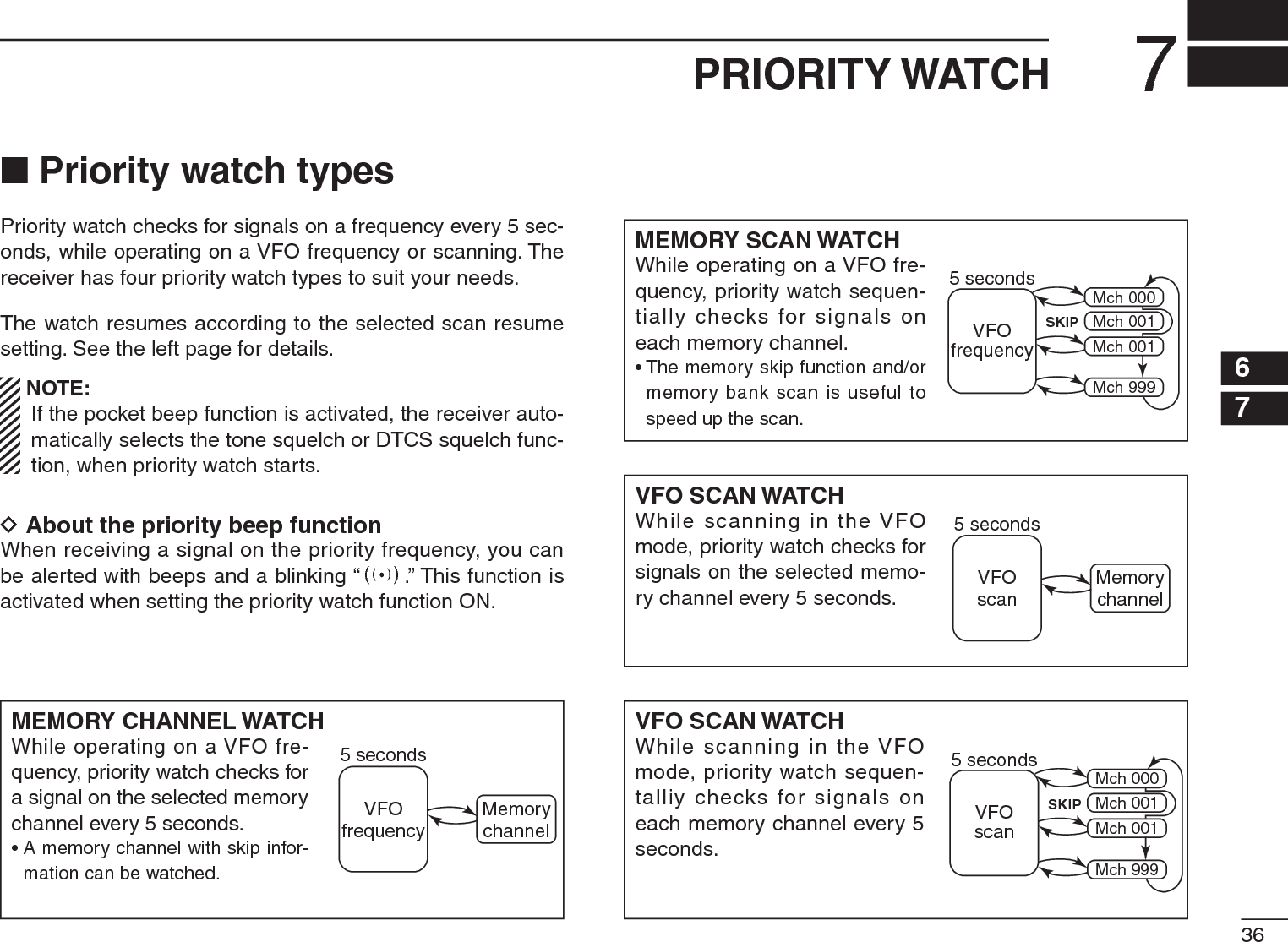
![377PRIORITY WATCHNPriority watch operationD Memory channel/memory scan watchqSelect the VFO mode; then, set an operating frequency.wSelect the channel(s) to be watched.For memory channel watch:Select a desired memory channel.For memory scan watch:± Push [V/M] to select the memory mode.±Hold down [SCAN](MODE) for 1 second to enter the scan type selection mode.±Rotate [DIAL] to select a desired scan type, then push [SCAN](H/M/L) again to start the memory/bank scan.eHold down [SET](TS) for 1 second to enter the Set mode.rRotate [DIAL] to select the priority watch set item.t While holding down [FUNC], rotate [DIAL] to select “ON.”• Select “BELL” if the priority beep function is desired.[DIAL]After 1 sec.Priority ONyPush [TS] to exit the Set mode and start the watch.• The “PRIO” icon appears.• The receiver checks the memory/bank channel(s) every 5 sec-onds.• The watch resumes according to the selected scan resume set-ting. (p. 31)During priority watchMonitors VFO frequencyfor 5 seconds.Pauses on a memorychannel when a signal isreceived.During priority watch with the priority beepA beep tone sounds and “S” icon blinks when a signalis received on a memory channel.uPush [SET](TS) to cancel the watch.](https://usermanual.wiki/ICOM-orporated/325000/User-Guide-1227030-Page-50.png)
![387PRIORITY WATCH7D VFO scan watchqSelect the channel(s) to be watched.For memory channel watch:Select a desired memory channel.For memory scan watch:± Push [V/M] to select the memory mode.±Hold down [SCAN](MODE) for 1 second to enter the scan type selection mode.±Rotate [DIAL] to select a desired scan type, then push [SCAN](H/M/L) again to start the memory/bank scan.wHold down [SET](TS) for 1 second to enter the Set mode.eRotate [DIAL] to select the priority watch set item.r While holding down [FUNC], rotate [DIAL] to select “ON.”• Select “BELL” if the priority beep function is desired.After 1 sec.tPush [SET](TS) to exit the Set mode and start the watch.• The “PRIO” icon appears.y Hold down [SCAN](MODE) for 1 second to enter scan type selection mode.u Rotate [DIAL] to select a desired scan type from “ALL,” “BAND,” “P-LINK x (x= 0 to 9)”or “PROGxx (xx= 0–24).”iPush [SCAN](MODE) to start the VFO scan watch.• The receiver checks the memory channel(s) every 5 seconds.• The watch resumes according to the selected scan resume set-ting. (p. 31)During VFO watchSearches VFO frequen-cies for 5 seconds.Pauses on a memorychannel when a signal isreceived.During VFO scan watch with the priority beepA beep tone sounds and “S” icon blinks when a signalis received on a memory channel.oPush [TS] to cancel the watch and scan.](https://usermanual.wiki/ICOM-orporated/325000/User-Guide-1227030-Page-51.png)
 for 1 second to enter the Set mode.eRotate [DIAL] to select the “EXPAND” item.r While holding down [FUNC], rotate [DIAL] to turn the Expand set mode ON.tRotate [DIAL] to select the “TSQL” item.y While holding down [FUNC], rotate [DIAL] to select a desired subaudible tone setting from “TSQLS,” “TSQL,” “DTCS,” “DTCSS,” “TSQL (reverse),” “DTCS (reverse)” or “OFF.”Tone squelchDTCS squelchTone squelch (reverse)DTCS squelch (reverse)Tone squelch with pocket beepDTCS squelch with pocket beepuPush [SET](TS) to exit the Set mode.• One of “S T SQL,” T SQL,” “SDTCS,” “DTCS,” “T SQL-R” or “DTCS -R” appears according to the tone selection in step y.Tone squelchDTCS squelchDTCS squelch (reverse)Tone squelch (reverse)Tone squelch with pocket beepDTCS squelch with pocket beepi When a signal with the matched tone is received, the squelch opens and the receiver emits audio. When pocket beep function is activated, the receiver also emits beep tones and blinks “S.”• Beep tones sound and “S” blinks for 30 seconds.oPush [FUNC] to stop the beeps and blinking manually.• “S” disappears and the pocket beep function is deactivated.!0 To cancel the tone squelch or DTCS, select “OFF” with the “TSQL” item in the Expand set mode, as described in step y.](https://usermanual.wiki/ICOM-orporated/325000/User-Guide-1227030-Page-52.png)
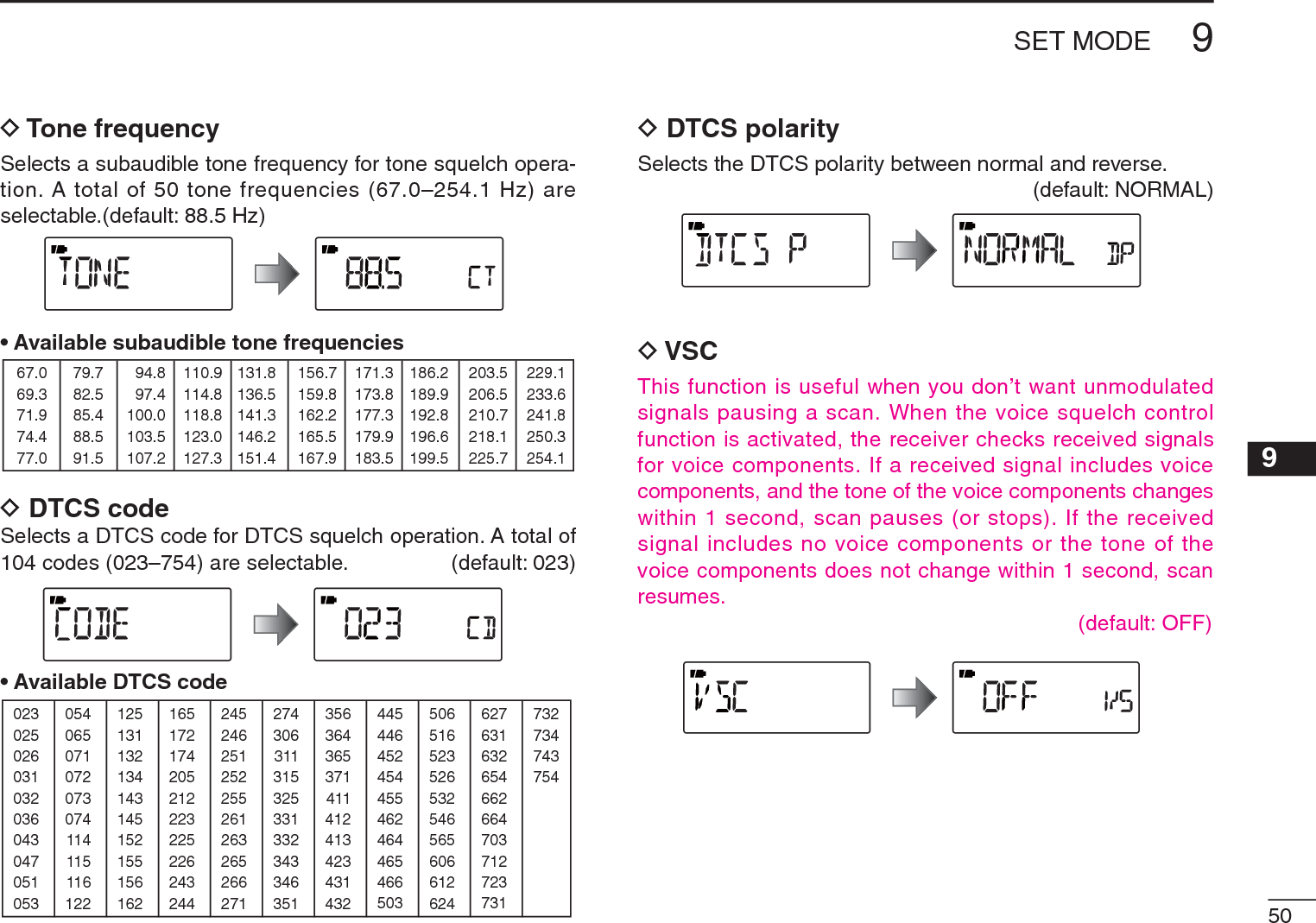
 for 1 second to enter the Set mode.wRotate [DIAL] to select the “EXPAND” item.e While holding down [FUNC], rotate [DIAL] to turn the Expand set mode ON.r Rotate [DIAL] to select the “TONE” item when selecting the tone squelch frequency; select the “CODE” item when selecting the DTCS code.After1 sec.After1 sec.Tone squelch frequency selectionDTCS code selectiont While holding down [FUNC], rotate [DIAL] to select a desired subaudible tone frequency or DTCS code.• See the tables at right.yPush [SET](TS) to exit the Set mode.•Available tone frequency list67.069.371.974.477.079.782.585.488.591.594.897.4100.0103.5107.2110.9114.8118.8123.0127.3131.8136.5141.3146.2151.4156.7159.8162.2165.5167.9171.3173.8177.3179.9183.5186.2189.9192.8196.6199.5203.5206.5210.7218.1225.7229.1233.6241.8250.3254.1NOTE: The receiver has 50 tone frequencies and conse-quently their spacing is narrow compared to units having 38 tones. Therefore, some tone frequencies may receive interference from adjacent tone frequencies.•Available DTCS code list023025026031032036043047051053125131132134143145152155156162245246251252255261263265266271356364365371411412413423431432506516523526532546565606612624054065071072073074114115116122165172174205212223225226243244274306311315325331332343346351445446452454455462464465466503627631632654662664703712723731732734743754](https://usermanual.wiki/ICOM-orporated/325000/User-Guide-1227030-Page-53.png)
 for 1 second to enter the Set mode.wRotate [DIAL] to select the “EXPAND” item.e While holding down [FUNC], rotate [DIAL] to turn the Expand set mode ON.r Rotate [DIAL] to select the “DTCS P” item.[DIAL]After 1 sec.t While holding down [FUNC], rotate [DIAL] to select the polarity from normal (NORMAL) and reverse (REV).Normal polarity Reverse polarityyPush [SET](TS) to exit the Set mode.](https://usermanual.wiki/ICOM-orporated/325000/User-Guide-1227030-Page-54.png)
![428TONE SQUELCH AND POCKET BEEP 8N Tone scanBy monitoring a signal that is being operated with pocket beep, tone or DTCS squelch function, you can determine the tone frequency or DTCS code necessary to open a squelch.q Set the frequency to be checked for a tone frequency or code.w Turn a desired tone type, tone squelch or DTCS ON in the Expand set mode.• One of “TSQL” or “DTCS” appears. • Even the pocket beep function is activated, the function is can-celled when starts the tone scan.e While holding down [FUNC], push [ ](MODE) to start the tone scan.• To change the scanning direction, rotate [DIAL].[DIAL] Tone squelch scanDTCS squelch scanrWhen the CTCSS tone frequency or 3-digit DTCS code is matched, the squelch opens and the tone frequency or code is temporarily programmed into the selected condi-tion, such as memory channel.• The tone scan pauses when a CTCSS tone frequency or 3-digit DTCS code is detected.NOTE: The decoded tone frequency or code is pro-grammed temporarily when a memory channel is selected. However, this will be cleared when the other memory chan-nel is selected. For your convenient!Even no tone type is selected, either tone squelch or DTCS, pushing [ ](MODE) while holding down [FUNC] also start tone scan. In this case, the tone scan searching for tone squelch frequency only.](https://usermanual.wiki/ICOM-orporated/325000/User-Guide-1227030-Page-55.png)
 for 1 second to enter the Set mode.wRotate [DIAL] to select a desired item.e While holding down [FUNC], rotate [DIAL] to select a desired value or option.r Push [SET](TS) to exit the Set mode, or repeat w and eto set other items.[DIAL]D Expand set mode ON/OFFqHold down [SET](TS) for 1 second to enter the Set mode.wRotate [DIAL] to select the “EXPAND” item.e While holding down [FUNC], rotate [DIAL] to turn the Expand set mode ON or OFF.Expand set mode OFF Expand set mode ONrRotate [DIAL] to select a desired item.t While holding down [FUNC], rotate [DIAL] to select a desired value or option.y Push [SET](TS) to exit the Set mode, or repeat r and tto set other items.](https://usermanual.wiki/ICOM-orporated/325000/User-Guide-1227030-Page-56.png)
![459SET MODED Dial select stepSelect the tuning step between 100 kHz, 1 MHz (default) and 10 MHz for a temporary faster frequency setting. When setting a frequency with the increased tuning step, hold down [FUNC], and then rotate [DIAL].D Priority watchTurn the priority watch or priority beep (priority watch with beep sounds) ON. (default: OFF)• OFF : Turns the function OFF.• ON : Starts priority watch after exiting the Set mode.• BELL : When a signal is received on the priority fre-quency, beeps sound and the ((*)) icon blinks. D Key-touch beepThe key-touch beep can be turned OFF for silent operation. (default: ON)D Beep output levelAdjust the key-touch beep tone level to one of 32 set levels, or set it to follow the volume control level. • VOLUME : The beep tone level is linked to the vol-ume set level. (default)• _ _ _ _ _ _ – ooo ooo : The beep tone level is independently adjustable at one of 32 levels.The key-touch beep (previous item) must be set to ON to have a beep tone.](https://usermanual.wiki/ICOM-orporated/325000/User-Guide-1227030-Page-58.png)
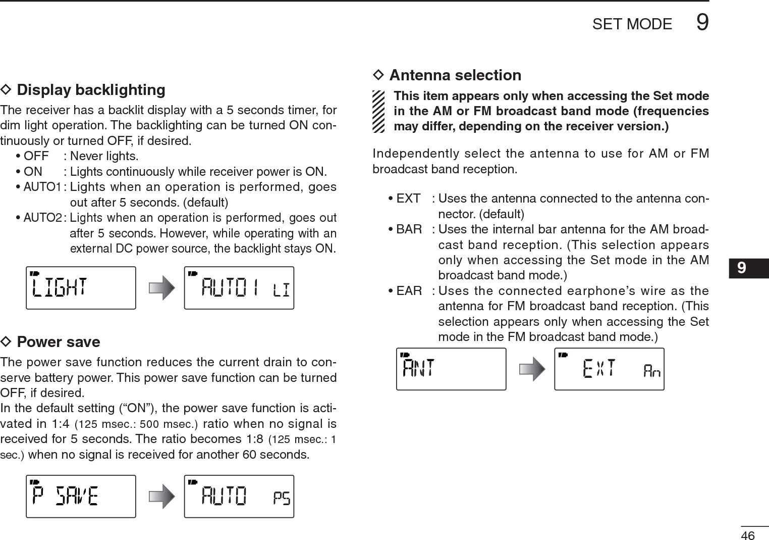
![479SET MODED Expand set modeTurn the Expand set mode ON or OFF.• OFF : Displays only the regular set mode. (default)• ON : Displays the regular set mode and the expand set mode.D Key lock effectEven while the key lock function is ON, [Y]/[Z] and [SQL]can still be usable. Usable switches can be set to one of 4 groups.[] and [FUNC]+[ ](BAND) are also usable during the locked state, however, these switches are not effected by this setting.• NORMAL : [Y]/[Z] and [SQL] are accessible. (default)• NO SQL : [SQL] is accessible. (The function of [SQL] is not locked.)*• NO VOL : [Y]/[Z] are accessible. (The function of [Y]/[Z is not locked.)*• ALL : No key function is usable, except [] and [FUNC]+[ ](BAND).*“NO” indicates no lock on the function.D Dial speed accelerationThe dial speed acceleration automatically speeds up the tuning dial speed, when rotating [DIAL] rapidly.• OFF : The dial speed acceleration is turned OFF.• ON : The dial speed acceleration is tuned ON. (default)D Monitor switch actionThe monitor switch, [SQL], can be set as a ‘sticky’ switch. When set to the sticky condition, each push of [SQL] toggles the monitor function ON or OFF.• PUSH : Pushing and holding [SQL] to monitor the fre-quency. (default)• HOLD : Push [SQL] momentarily to monitor the fre-quency and push momentarily again to cancel it.](https://usermanual.wiki/ICOM-orporated/325000/User-Guide-1227030-Page-60.png)
![489SET MODE9D Auto power OFFThe receiver can be set to automatically turn OFF, and sound a beep, after a specified period when no key opera-tions are performed.OFF (default), times of 30 minutes, 1 hour, 1.5 hours, 2 hours and BUSY can be specified. The (repetitive) period is retained even when the receiver is turned OFF, even by the auto power OFF function. To cancel the function, select “OFF”.D Scan pause timerSelects the scan pause time. When receiving signals, the scan pauses according to the scan pause time.• 2–20 : The scan pauses for 2–20 seconds on a received signal, and is selected in 2 second steps. (default: 10 seconds)• HOLD : The scan pauses on a received signal until it disappears. Rotate [DIAL] to resume manually.D Scan resume timerSelects the scan resume time. The scan resumes after the specified period after the received signal disappears.• 0 : The scan resumes immediately after the received signal disappears.• 1–5 : The scan pause 1–5 seconds after the received signal disappears. (default: 2 seconds)• HOLD : The scan pauses on the received signal, even if it disappears. Rotate [DIAL] to resume manu-ally.D Scan stop beepTurns the scan stop beep function ON or OFF (default). When the function is activated (“ON” is selected), a long beep will sound each time when signal is received during a scan.](https://usermanual.wiki/ICOM-orporated/325000/User-Guide-1227030-Page-61.png)
![499SET MODED Frequency offsetSets the frequency offset for each frequency band independ-ently within 0 to 159.995 MHz range. During duplex opera-tion (–DUP or +DUP), the monitoring frequency (while [SQL]is pushed) shifts the set frequency. The default value may differ depending on the selected frequency band, before accessing the Set mode, and the receiver version.The selected tuning step in the VFO mode is used for the frequency offset setting.D Duplex directionSelects the duplex direction. The displaying frequency shifts the programmed frequency in frequency offset above when monitor function is in use (while holding down [SQL]).• OFF : Simplex operation. (default)• –DUP : The displayed frequency shifts down dur-ing monitor.• +DUP : The displayed frequency shifts up during monitor.D Tone squelch Selects the tone or DTCS squelch operation and pocket beep capability, when waiting for a desired signal. • OFF : Regular noise squelch operation. (default)• TSQL(( )) : In addition to the “TSQL” setting, alert beeps will sound when a signal with the matched subaudible tone is received.• TSQL : Selects tone squelch. The squelch opens only when a signal with a matched subaudi-ble tone is received.• DTCS(( )) : In addition to the “DTCS” setting, alert beeps will sound when a signal with a matched DTCS code is received.• DTCS : Selects DTCS squelch. The squelch opens only when a signal with a matched DTCS code is received.• TSQL-R : Selects reverse tone squelch. The squelch becomes mute only when a signal with a matched subaudible tone is received.• DTCS-R : Selects reverse DTCS squelch. The squelch becomes mute only when a signal with a matched DTCS code is received.The subaudible tone frequency is programmed in the tone frequency and DTCS code is programmed into the DTCS code option.](https://usermanual.wiki/ICOM-orporated/325000/User-Guide-1227030-Page-62.png)
![519SET MODED Memory bank link function (B-LINK)Turns the memory bank link function ON (default) or OFF. The link function provides continuous bank scan, scanning all channels in the selected banks during bank scan.• Bank link settingqPush [MODE] to enter the bank link setting mode.wRotate [DIAL] to select a bank that you want to change the link setting.eWhile holding down [FUNC], rotate [DIAL] to set the link setting ON or OFF.Setting is ON Setting is OFFrRepeat steps w and e until the bank link setting is fin-ished.tPush [TS] to exit the bank link setting mode.D Program scan link function (P-LINK)Sets the program scan link function. During program scan, link function performs a continuous program scan in the se-lected program scan number during program scan.Default settings for LINK0 to LINK9;PROG 1 to PROG 24 are linked, but PROG 0 is not linked.• Confirming program scan linkqPush to [MODE] to enter the program scan link setting.wRotate [DIAL] to select the program scan link number that you want to confirm, then push [MODE].• “LINK” appears.ePush [MODE], then rotate [DIAL] to confirm the linked program scans.rPush [TS] three times to exit the program scan link setting.](https://usermanual.wiki/ICOM-orporated/325000/User-Guide-1227030-Page-64.png)
![529SET MODE12345678910111213141516• Program scan link settingqPush to [MODE] to enter the program scan link setting.wRotate [DIAL] to select the program scan link number that you want to change.ePush [MODE], then rotate [DIAL] to select the option, “ADD” or “CLEAR”.rRotate [DIAL] to select the desired program scan.• When “ADD” is selected in step e, only non-linked pro-gram scans are displayed. When “CLEAR” is selected in step e, only linked program scans are displayed.tPush [MODE] to set the program scan link setting.yRepeat steps r and t to add or clear the program scan to or from the link, or push [TS] twice to exit the program scan link setting.• Program scan link name programmingqPush to [MODE] to enter the program scan link setting.wRotate [DIAL] to select the program scan link number that you want to change.ePush [MODE], then rotate [DIAL] to select “NAME.”rPush [MODE] to enter the name programming.tWhile holding down [FUNC], rotate [DIAL] to select the desired character, number, symbol or space. • Rotate [DIAL] right or left to move the cursor right or left, respectively.yWhen finishing entering a name, push [MODE] to set the name and then exit the name programming.uPush [TS] twice to exit the program scan link setting.i Push [TS] to exit the Set mode.](https://usermanual.wiki/ICOM-orporated/325000/User-Guide-1227030-Page-65.png)
![55OTHER FUNCTIONS10N [DIAL] function assignmentThe [DIAL] control can be used as an audio volume control, instead of [Y]/[Z] keys. However, while [DIAL] functions as an audio volume control, the [Y]/[Z] keys function as tuning controls.± While holding down [FUNC], push [ ](TS) to toggle the [DIAL] function between tuning dial and audio volume.•“ ” icon appears when [DIAL] functions as the volume control.“VOL” appears while[DIAL] functions as theaudio volume control.• [DIAL] and [Y]/[Z]] functionsN Weather channel operationU.S.A. version onlyD Weather channel selectionq Push [V/M] to select the VFO mode, if any other mode is selected.w While holding down [BAND], rotate [DIAL] to select the weather channel group.• The weather channel group can also be selected by pushing [BAND] repeatedly.eRotate [DIAL] to select a desired weather channel. [DIAL]Weather channel displayr Push [BAND] to change frequency band, or push [V/M] to select the memory mode.No “VOL” icon “VOL” appearsFrequency, Memory channel,Audio volume [DIAL] Squelch level, Scanningdirection, Set mode item and condition setAudio volume setFrequency, Memory channel,[Y]/[Z]Squelch level, Scanning direction, Set mode item and condition set](https://usermanual.wiki/ICOM-orporated/325000/User-Guide-1227030-Page-68.png)
 to enter the Set mode.±Rotate [DIAL] to select the weather alert option. Then, while holding down [FUNC], rotate [DIAL] to set “ON”. ± Push [SET](TS) to exit the Set mode.eSet a desired stand-by condition.• Select the VFO or a memory channel.• Scan or priority watch operation can also be selected.r When the alert is detected, a beep sounds and the follow-ing indicator will be displayed.The above icons are alternately displayed.t Turn the weather alert function OFF in the Set mode.NOTE: While receiving a signal (on a frequency other than the weather alert ON frequency), the receiving signal or audio will be interrupted momentarily every 5 seconds (approx.) when the alert function is turned ON. This is caused by the WX alert function. To eliminate the interrup-tion, set the weather alert item OFF in the Set mode.](https://usermanual.wiki/ICOM-orporated/325000/User-Guide-1227030-Page-69.png)
![5710 OTHER FUNCTIONSN Data cloningCloning allows you to quickly and easily transfer the pro-grammed contents from one receiver to another; or data from a personal computer to a receiver, using the optional CS-R6 CLONING SOFTWARE.DCloning between receiversq Connect the OPC-474 cloning cable to the [SP] jack of the master and sub-receivers.• The master receiver is used to send data to the sub-receiver.to [SP]MasterreceiverSubreceiverto [SP]NOTE: DO NOT push any key on the sub-receiver during cloning. This will cause a cloning error.w While holding down [V/M], turn only the master receiver power ON, to enter the cloning mode (master receiver only— power ON only for sub-receiver).Master receiver“CLONE” and “m” appearwhen entered the cloningmode.e Push [SQL] on the master receiver.• The receiver displays the following.During cloningAfter cloningMaster receiver display Sub-receiver displayr When cloning is finished, turn power OFF, then ON to exit the cloning mode.](https://usermanual.wiki/ICOM-orporated/325000/User-Guide-1227030-Page-70.png)
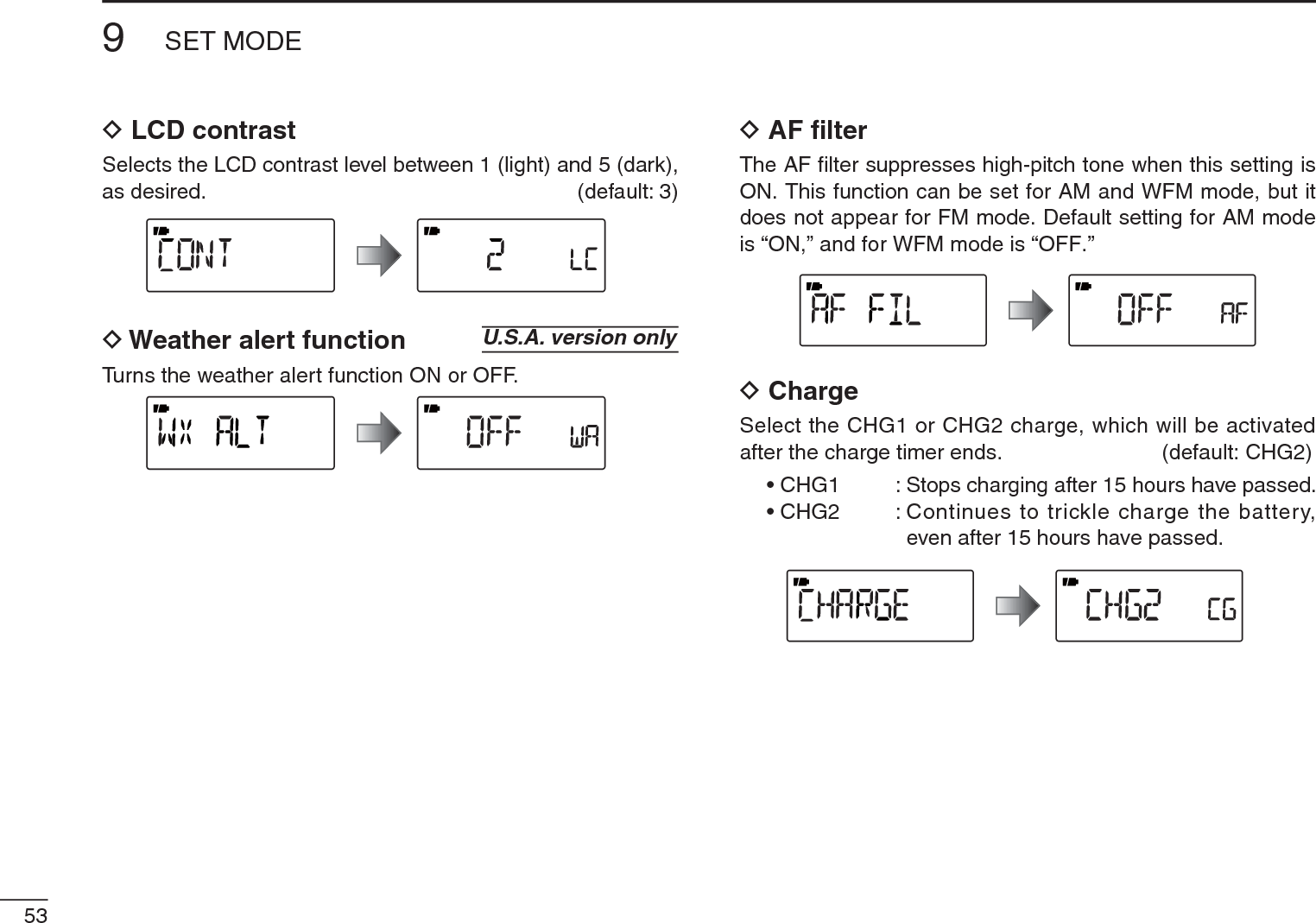
 for 1 second to enter the Set mode.wRotate [DIAL] to select the “AP OFF” item.• Turn the Expand set mode ON for selection. (p. 39)[DIAL]e While holding down [FUNC], rotate [DIAL] to select a desired time or to turn the function OFF.rPush [SET](TS) to exit the Set mode.Microsoft, Windows and Windows Vista are registered trademarks of Microsoft Corporation in the U.S.A. and other countries.](https://usermanual.wiki/ICOM-orporated/325000/User-Guide-1227030-Page-71.png)
![5910 OTHER FUNCTIONSN Partial resetIf you want to initialize the operating settings (VFO frequen-cy, VFO settings, Set mode contents) without clearing the memory contents, a partial resetting function is available for the receiver.±While holding down [FUNC] and [TS], turn the power ON to partially reset the receiver.N All resetThe function display may occasionally display erroneous information (e.g. when first applying power). This may be caused externally by static electricity or by other factors.If this problem occurs, turn power OFF. After waiting a few seconds, turn power ON again. If the problem persists, per-form the following procedure.• Partial resetting is also available. See to the left for details.IMPORTANT!:Resetting the receiver CLEARS all memory informa-tion and initializes all values in the receiver, including TV channel skip setting.±While holding down [FUNC] and [Z], turn the power ON to reset the CPU.*The appearing frqeuencyis differ according toreceiver version.±While holding down [FUNC] and [TS], turn the power OFF, then ON again to partially reset the receiver.](https://usermanual.wiki/ICOM-orporated/325000/User-Guide-1227030-Page-72.png)
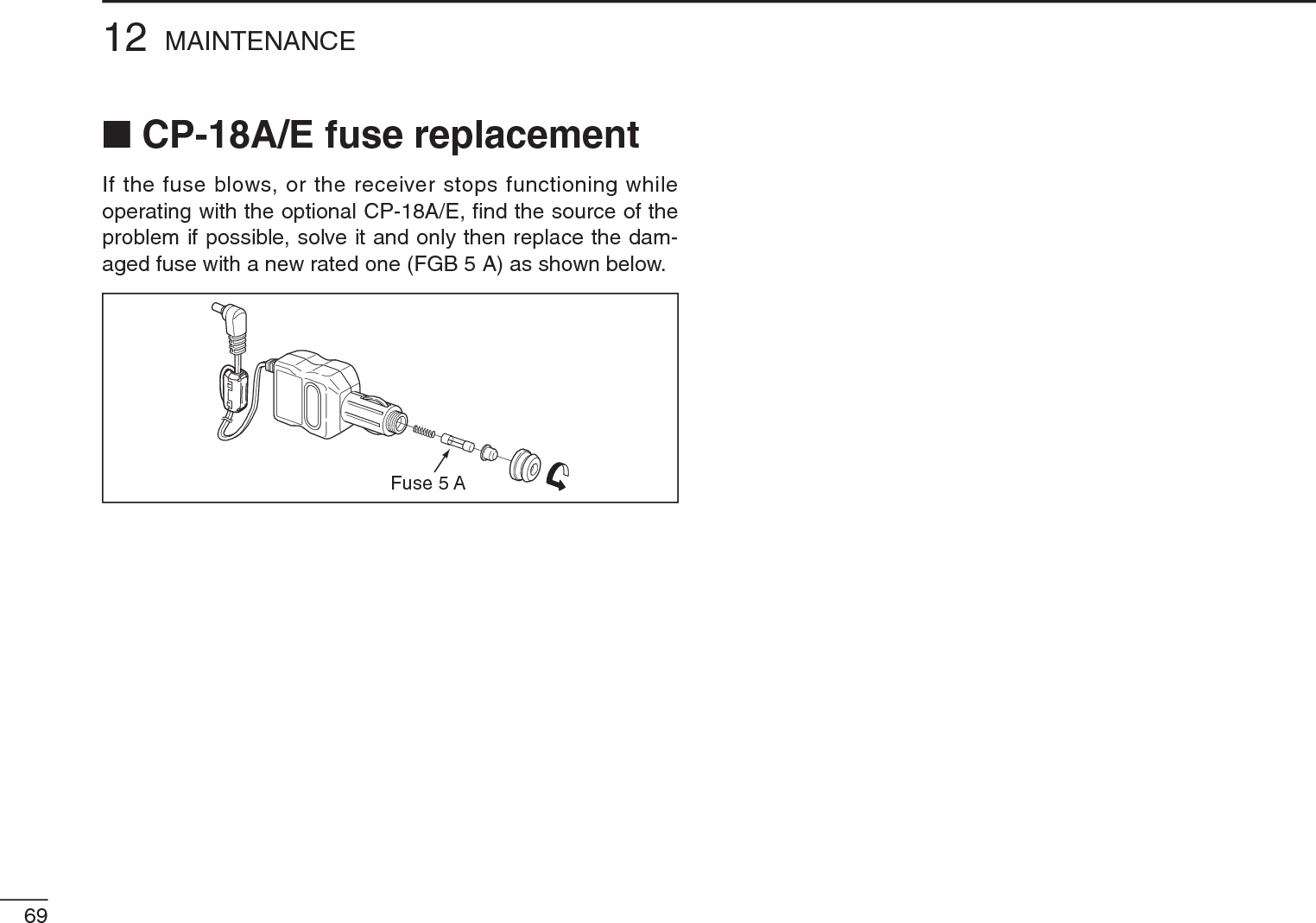
![6812MAINTENANCE1112PROBLEM POSSIBLE CAUSE SOLUTION REF.N Troubleshooting If your receiver seems to be malfunctioning, please check the following points before sending it to a service center.No power comes on.No sound comes from the speaker.Sensitivity is low and only strong signals are audible.Frequency cannot be set.No beep sound.Receive audio is distorted.Desired Set mode item cannot be selected.Programmed scan does not start.Memory or bank scan does not start.Installed batteries cannot be charged.• The batteries are exhausted.• The battery polarity is reversed.• Volume level is too low.• Squelch level is set too tight.• Different tone is selected with tone squelch.• Attenuator function is activated.• The lock function is activated.• Beep tones are turned OFF or the beep tone level is too low.• The operating mode is not selected correctly.• “EXPAND” item is set to OFF.• Some Set mode items can be selected in the AM or FM broadcast band only.• Program scan edges are not programmed.• No or only one memory or bank channel is programmed.• The batteries over discharged.• Replace the batteries or charge the batteries.• Check the battery polarity. • Push [Y] to obtain a suitable level.• While holding down [SQL], rotate [DIAL] to set the squelch level.• Turn the appropriate function OFF.• While holding down [FUNC], push [SQL] to turn the attenuator function OFF.• While holding down [FUNC], push [](BAND) for 1 second to turn the function OFF.• Turn beep tone ON or set the beep tone level to appropriate level in the Set mode.• Push [MODE] repeatedly to select a suitable operating mode.• Turn “EXPAND” item ON.• Choose the AM or FM broadcast band.• Program a pair of scan edge channels.• Program at least 2 memory or bank channels• Re-install the batteries (wait at least for 1 second), then plug the AC adapter while holding down [FUNC].pgs. 5, 6p. 5p. 11p. 12p. 35p. 13p. 10p. 41p. 12p. 39p. 7p. 27pgs. 16,17p. 6](https://usermanual.wiki/ICOM-orporated/325000/User-Guide-1227030-Page-81.png)
![qwiR6VFO and memory mode selectionPOCKET GUIDEPush [V/M] to toggle between theVFO and the memory mode. Receive mode selectionPush [MODE] repeatedly toselect the desired mode Audio level settingPush [Y] to increase, push [Z]to decrease the audio level. Squelch level settingHold down [SQL], rotate [DIAL]to set the squelch level. Frequency band selectionPush [BAND] repeatedly, or holddown [BAND], rotate [DIAL] toselect the desired frequency band. Tuning step selectionPush [TS], then rotate [DIAL] toselect the desired tuning step.• Push [TS] again to return to theprevious screen.Key lock functionHold down [FUNC], push [ ](BAND) for 1 sec. to toggle thekey lock function ON or OFF.• “ ” appears when the lock functionis in use. Frequency settingPush [V/M] to select the VFOmode.Rotate [DIAL] to set the desiredoperating frequency. qw Memory channel selectionPush [V/M] to select thememory mode.Rotate [DIAL] to set a desiredmemory channel.• Hold down [FUNC], rotate [DIAL]changes memory channel in 10channel steps.qwe Memory bank channel selectionPush [V/M] to select thememory mode.Push [BAND] repeatedly, orwhile holding down [BAND],rotate [DIAL] selects a desiredbank.Rotate [DIAL] to select thedesired bank channel. Attenuator functionHold down [FUNC], push [ ](SQL) to toggle the attenuatorON or OFF.• “ATT” appears when the attenua-tor function is in use.7215POCKET GUIDEImportant operating instructions are summed up on this and the followingpage for your simple reference.By cutting along the line and folding on the dotted line, it will become acard sized operating guide which can easily be carried in a card case orwallet, etc.q Cut w Fold e Complete<CUT HERE>](https://usermanual.wiki/ICOM-orporated/325000/User-Guide-1227030-Page-85.png)
 for 1 sec. to enter the select memory write mode.• 1 short and 1 long beeps sound.Rotate [DIAL] to select a desired memory channel.Push and hold [S.MW](V/M) for 1 sec. to program the contents into the selected channel.• 3 beeps sound.qwe Scan skip settingPush [V/M] to select the memory mode.Rotate [DIAL] to select a desired memory channel.Hold down [FUNC], push [ ](V/M) to set the skip setting (skip channel or skip frequency) ON or OFF.qw VFO scansPush [V/M] to select the VFO mode.Push and hold [SCAN] (MODE) for 1 sec.• A scan type appears. ertRotate [DIAL] to select the desired scan type.Push [SCAN] (MODE) to start the scan.• Rotate [DIAL] to change the scanning direction.• During scan, push [V/M] to start the auto memory write scan.Push [SCAN](MODE) again to stop the scan.qw Memory scansPush [V/M] to select the memory mode.Push and hold [SCAN](MODE) for 1 sec.• A scan type appears.ertRotate [DIAL] to select the desired scan type.Push [SCAN] (MODE) to start the scan.• Rotate [DIAL] to change the scanning direction.Push [SCAN](MODE) again to stop scan.CE Versions of the IC-R6 which display the ‘CE’symbol on the serial number label, comply withthe essential requirements of the EuropeanRadio and Telecommunication Terminal Direc-tive 1999/5/EC7316 CE• List of Country codes (ISO 3166-1)Country Codes Country Codes1 Austria AT 18 Liechtenstein LI2 Belgium BE 19 Lithuania LT3 Bulgaria BG 20 Luxembourg LU4 Croatia HR 21 Malta MT5Czech Republic CZ 22 Netherlands NL6 Cyprus CY 23 Norway NO7 Denmark DK 24 Poland PL8 Estonia EE 25 Portugal PT9 Finland FI 26 Romania RO10 France FR 27 Slovakia SK11 Germany DE 28 Slovenia SI12 Greece GR 29 Spain ES13 Hungary HU 30 Sweden SE14 Iceland IS 31 Switzerland CH15 Ireland IE 32 Turkey TR16 Italy IT 33 United Kingdom GB17 Latvia LV](https://usermanual.wiki/ICOM-orporated/325000/User-Guide-1227030-Page-86.png)