ICOM orporated 325000 Communications Receiver User Manual
ICOM Incorporated Communications Receiver
Users Manual
INSTRUCTION MANUAL
iR6
COMMUNICATIONS RECEIVER
This device complies with Part 15 of the FCC Rules. Operation
is subject to the following two conditions: (1) this device may
not cause harmful interference, and (2) this device must accept
any interference received, including interference that may cause
undesired operation.
WARNING: MODIFICATION OF THIS DEVICE TO RECEIVE
CELLULAR RADIOTELEPHONE SERVICE SIGNALS IS
PROHIBITED UNDER FCC RULES AND FEDERAL LAW.
i
FOREWORD
Thank you for purchasing this Icom product. The IC-R6
COMMUNICATIONS RECEIVER is designed and built with Icom’s
superior technology and craftsmanship. With proper care,
this product should provide you with years of trouble-free
operation.
We want to take a moment of your time to thank you for mak-
ing your IC-R6 your radio of choice, and hope you agree with
Icom’s philosophy of “technology first.” Many hours of research
and development went into the design of your IC-R6.
D FEATURES
Covers 0.100–1309.995 MHz* wide
frequency range
*
Some frequency bands are inhibited
, depending on the
version
External power supply operation
1350 memory channels* with 22 banks
available
*Including 200 auto write and 50 scan edge channels
Built-in bar-antenna
New DMS (Dynamic Memory Scan) System
IMPORTANT
READ ALL INSTRUCTIONS carefully and completely
before using the receiver.
SAVE THIS INSTRUCTION MANUAL— This
instruction manual contains important operating instructions
for the IC-R6.
EXPLICIT DEFINITIONS
WORD DEFINITION
R WARNING!
CAUTION
NOTE
Personal injury, fire hazard or electric shock
may occur.
Equipment damage may occur.
Recommended for optimum use. No risk of
personal injury, fire or electric shock.

ii
RWARNING! NEVER operate the receiver with a
earphone, headphones or other audio accessories at high
volume levels. Hearing experts advise against continuous
high volume operation. If you experience a ringing in your
ears, reduce the volume level or discontinue use.
RWARNING! NEVER operate the receiver while
driving a vehicle. Safe driving requires your full attention—
anything less may result in an accident.
RWARNING! NEVER connect the receiver to an AC
outlet. This may pose a fire hazard or result in an electric
shock.
RWARNING! NEVER throw a battery cell into a fire
since as internal battery gas can cause explosion.
RWARNING! NEVER disassemble the battery cell.
If the battery cell’s internal material (electrolyte liquid) gets
into your eyes, wash your eyes with water and obtain treat-
ment from an eye doctor immediately.
NEVER connect the receiver to a power source of more
than 6 V DC directly. This will damage the receiver.
NEVER connect the receiver to a power source using
reverse polarity. This will damage the receiver.
NEVER expose the receiver to rain, snow or any liquids.
The receiver may be damaged.
NEVER operate or touch the receiver with wet hands. This
may result in an electric shock or damage the receiver.
NEVER solder the battery cell. This may damage the bat-
tery.
DO NOT use or place the receiver in direct sunlight or
in areas with temperatures below –10°C (+14˚F) or above
+60°C (+140˚F).
DO NOT use harsh solvents such as benzine or alco-
hol to clean the transceiver, because they can damage the
transceiver’s surfaces.
Even when the receiver power is OFF, a slight current still
flows in the circuits. Remove batteries from the receiver
when not using it for a long time. Otherwise, the installed
batteries will become exhausted, and will need to be
recharged.
PRECAUTIONS

iii
FCC INFORMATION
• FOR CLASS B UNINTENTIONAL RADIATORS:
This equipment has been tested and found to comply with
the limits for a Class B digital device, pursuant to part 15 of
the FCC Rules. These limits are designed to provide reason-
able protection against harmful interference in a residential
installation. This equipment generates, uses and can radi-
ate radio frequency energy and, if not installed and used in
accordance with the instructions, may cause harmful inter-
ference to radio communications. However, there is no guar-
antee that interference will not occur in a particular instal-
lation. If this equipment does cause harmful interference to
radio or television reception, which can be determined by
turning the equipment off and on, the user is encouraged to
try to correct the interference by one or more of the following
measures:
• Reorient or relocate the receiving antenna.
• Increase the separation between the equipment and
receiver.
• Connect the equipment into an outlet on a circuit differ-
ent from that to which the receiver is connected.
• Consult the dealer or an experienced radio/TV techni-
cian for help.
OPERATING THEORY
Electromagnetic radiation, which has frequencies of
20,000 Hz (20 kHz*) and above, is called radio frequency
(RF) energy because, it is useful in radio transmissions. The
IC-R6 receives RF energy from 0.150 MHz* to 1309.995
MHz and converts it into audio frequency (AF) energy which
in turn actuates a loudspeaker to create sound waves.
AF energy is in the range of 20 to 20,000 Hz.
*kHz is an abbreviation of kilohertz or 1000 hertz, MHz is abbrevi-
ation of megahertz or 1,000,000 hertz, where hertz is a unit of fre-
quency.
OPERATING NOTES
The IC-R6 may receive its own oscillated frequency, result-
ing in no reception or only noise reception, on some fre-
quencies.
The IC-R6 may receive interference from extremely strong
signals on different frequencies or when using an external
high-gain antenna.
Icom, Icom Inc. and the Icom logo are registered trademarks of
Icom Incorporated (Japan) in Japan, the United States, the United
Kingdom, Germany, France, Spain, Russia and/or other countries.
CAUTION: Changes or modifications to this device, not
expressly approved by Icom Inc., could void your authority
to operate this device under FCC regulations.

iv
1
2
3
4
5
6
7
8
9
10
11
12
13
14
15
16
1
2
3
4
5
6
7
8
9
10
11
12
13
14
15
16
TABLE OF CONTENTS
FOREWORD ………………………………………………… i
IMPORTANT ………………………………………………… i
EXPLICIT DEFINITIONS …………………………………… i
PRECAUTIONS ……………………………………………… ii
FCC INFORMATION ……………………………………… iii
OPERATING THEORY …………………………………… iii
OPERATING NOTES ……………………………………… iii
TABLE OF CONTENTS ………………………………… iv–v
SUPPLIED ACCESSORIES ………………………………… v
QUICK REFERENCE GUIDE ………………………… I–VII
Preparation ……………………………………………… I
Your first scanning experience ……………………… III
Memory programming ……………………………… IV
Programmed scan operation ………………………… V
1 PANEL DESCRIPTION ……………………………… 1–4
Front, top and side panels ………………………… 1
Function display ……………………………………… 3
2 BATTERY CHARGING ……………………………… 5–8
Battery installation …………………………………… 5
Caution ………………………………………………… 5
Battery charging ……………………………………… 7
3 FREQUENCY AND CHANNEL SETTING ……… 9–18
VFO and memory channels ………………………… 9
Operating band selection …………………………… 9
Setting a frequency…………………………………… 11
Setting a tuning step ………………………………… 11
Selecting a memory channel………………………… 12
Lock function ………………………………………… 12
4 BASIC OPERATION ……………………………… 13–17
Receiving ……………………………………………… 13
Setting audio volume ………………………………… 13
Squelch level setting ………………………………… 14
Receive mode selection ……………………………… 14
Monitor function ……………………………………… 15
Attenuator function …………………………………… 15
Duplex operation ……………………………………… 16
Dial select step ……………………………………… 17
5 MEMORY CHANNELS …………………………… 18–27
General description…………………………………… 18
Selecting a memory channel………………………… 18
Memory channel programming ……………………… 19
Memory bank setting ………………………………… 20
Memory bank selection ……………………………… 21
Programming memory/bank name ………………… 22
Selecting display type………………………………… 23
Copying memory contents…………………………… 24
Memory clearing ……………………………………… 25
Transferring memory contents ……………………… 26
Erasing/transferring bank contents ………………… 27
6 SCAN OPERATION ……………………………… 28–35
Scan types …………………………………………… 28
Full/band/programmed link/programmed scan …… 29
Scan edges programming …………………………… 30
Memory/all bank/bank link/bank scan ……………… 31
Auto memory write scan …………………………… 32
Skip channel/frequency setting……………………… 34
Scan resume setting ………………………………… 35
v
7 PRIORITY WATCH ……………………………… 36–38
Priority watch types…………………………………… 36
Priority watch operation ……………………………… 37
8 TONE SQUELCH AND POCKET BEEP ……… 39–41
Tone/DTCS squelch operation ……………………… 39
Tone squelch frequency/DTCS code setting ……… 40
DTCS polarity setting ………………………………… 41
Tone scan ……………………………………………… 42
9 Set mode ………………………………………… 43–54
General ………………………………………………… 43
Set mode items ……………………………………… 44
10 OTHER FUNCTIONS …………………………… 55–59
[DIAL] function assignment ………………………… 55
Weather channel operation ………………………… 55
Data cloning ………………………………………… 57
Auto power-off function ……………………………… 58
Partial reset …………………………………………… 59
All reset ……………………………………………… 59
11 FREQUENCY TABLE …………………………… 60–67
TV channels …………………………………………… 60
VHF marine channels ………………………………… 63
Weather channels …………………………………… 63
Other communications in the USA ………………… 64
Other communications— other countries ………… 66
12 MAINTENANCE …………………………………… 68–69
Troubleshooting ……………………………………… 68
CP-18A/E fuse replacement ………………………… 69
13 SPECIFICATIONS ……………………………………… 70
14 OPTIONS ……………………………………………… 71
15 POCKET GUIDE ………………………………… 72–73
16 CE …………………………………………………… 73–74
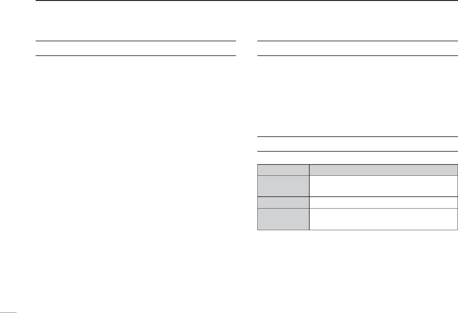
SUPPLIED ACCESSORIES
qw e
qAntenna …………………………………………………… 1
wHand strap ………………………………………………… 1
eBelt clip ……………………………………………………… 1
TABLE OF CONTENTS
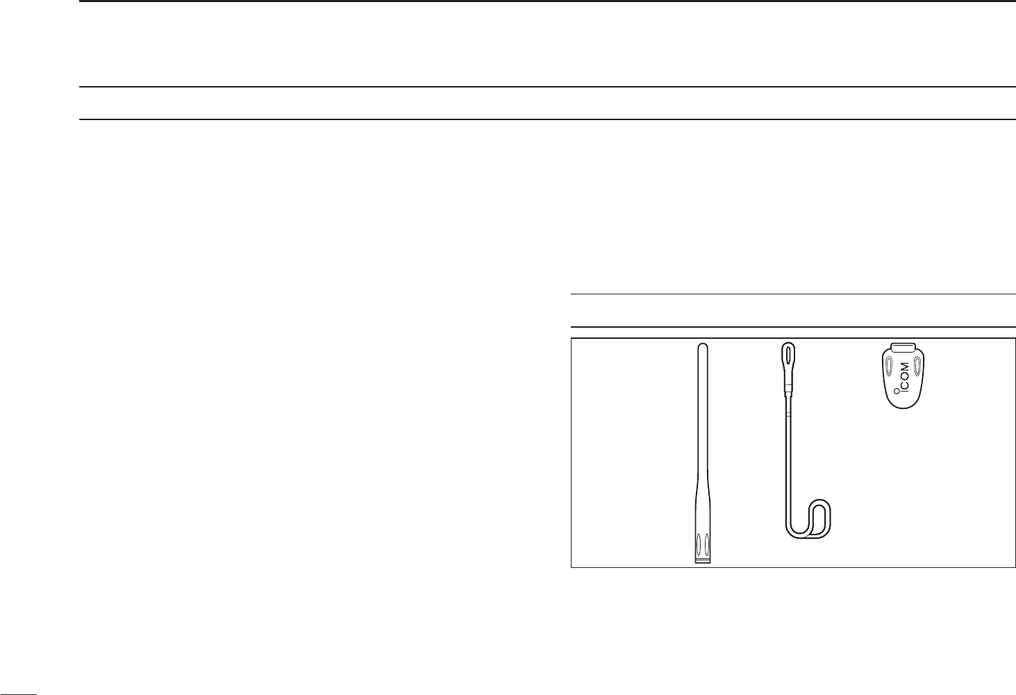
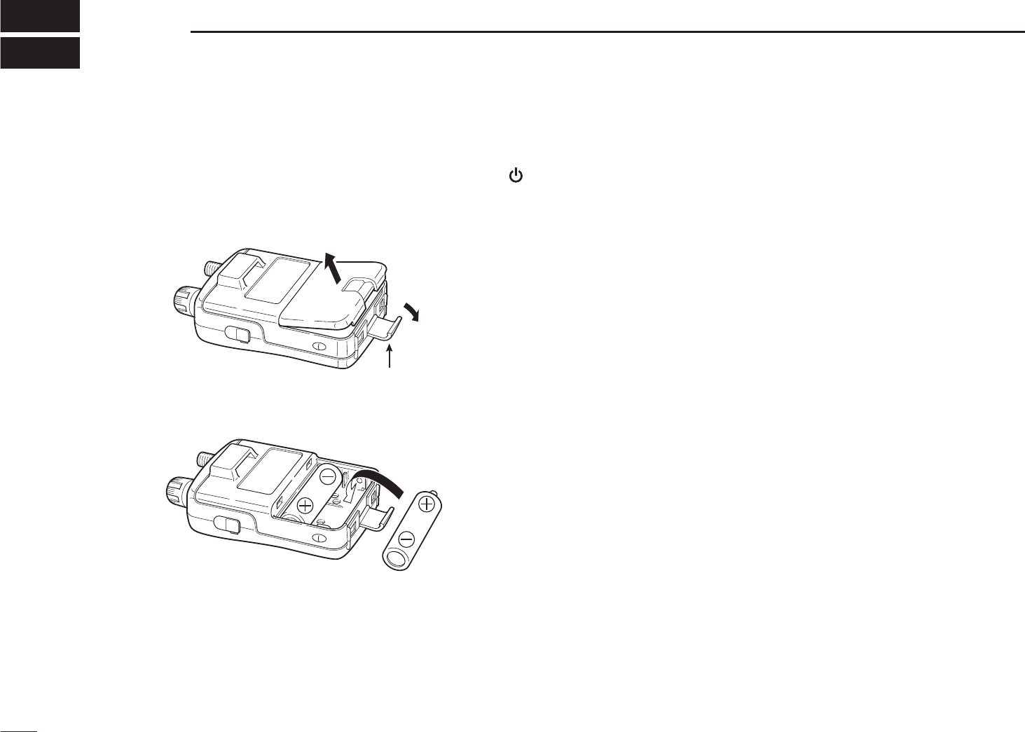
N Preparation
DBattery installation
qRemove the battery
cover from the receiver.
wInstall 2 R6(AA) size
Ni-MH or alkaline cell
batteries.
• Be sure to observe the
correct polarity.
• Charge the Ni-MH bat-
teries before use. (See
p.III for charging instruc-
tions.)
Keep the battery terminals clean. It’s a good idea to clean
the battery terminals once a week.
DBelt clip
Conveniently attaches to
your belt.
Slide the belt clip into the
plastic loop on the back of
the receiver.
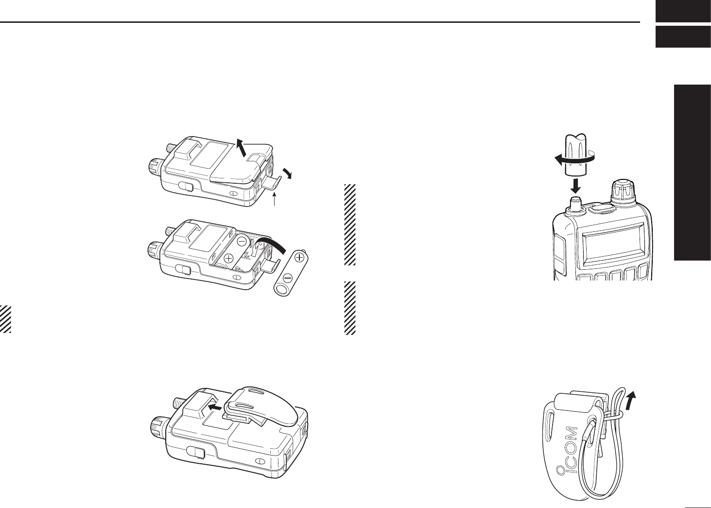
DAntenna
Insert the antenna connector into
the antenna base and tighten the
antenna screw.
• NEVER carry the receiver by
holding only the antenna.
• When the jack is not in use,
keep the jack cover attached
to protect the connectors from
dust and moisture.
For your information
Third-party antennas may increase receiver performance.
An optional AD-92SMA ANTENNA CONNECTOR ADAPTER is
available to connect an antenna with a BNC connector.
DHandstrap
To facilitate carrying the receiver,
slide the hand strap through the
loop on the top of the belt clip.
Latch
I
QUICK REFERENCE GUIDE
Quick reference guide
II
QUICK REFERENCE GUIDE
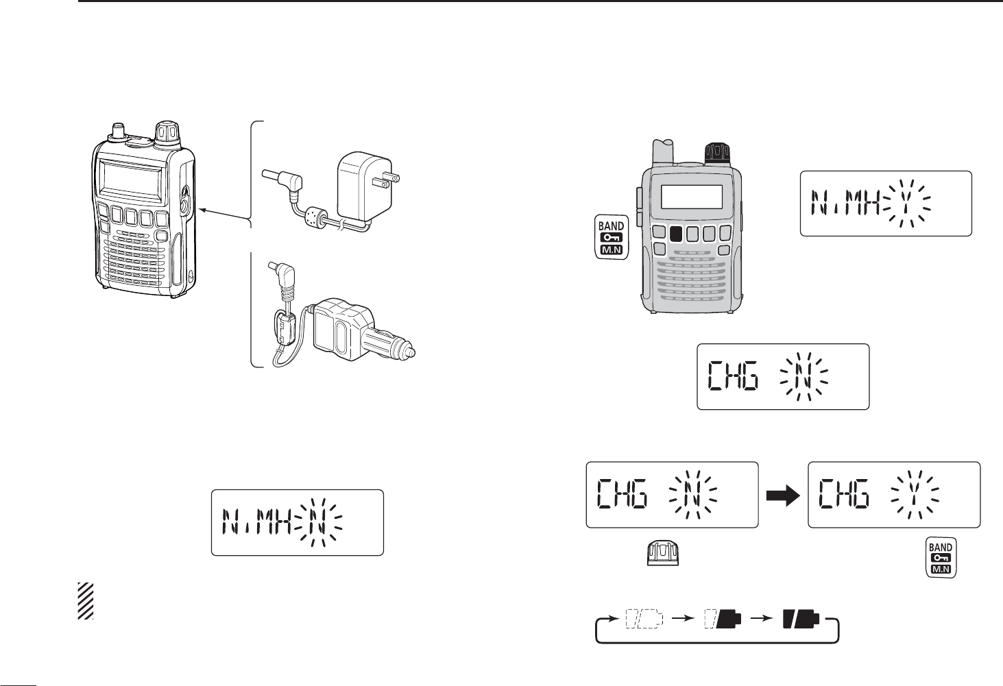
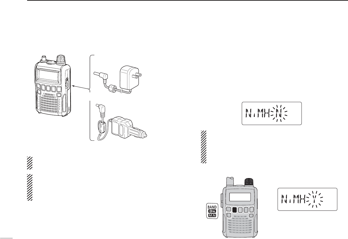
DCharging the battery
IC-R6
CP-18A/E
Cigarette lighter cable
with DC-DC converter
AC adapter
to a cigarette
lighter socket
The shape may
differ depending
on the version.
to an AC outlet
to the [DC4.5V]
jack
q Install the Ni-MH batteries.
w Plug the optional AC adapter into an AC outlet.
eInsert the optional adapter plug into the [DC4.5V] of the
receiver.
• The battery confirmation is displayed.
RWARNING!:
NEVER attempt to charge the alkaline batteries.
t Rotate [DIAL] to select “Y,” then push [BAND].
[DIAL]
• The charging confirmation is displayed.
uRotate [DIAL] to select “Y,” then push [BAND] to start the
battery charging.
Rotate Then, push
• The battery icon scrolls during charge.
• Both segments blink when completely charged.
III
QUICK REFERENCE GUIDE
Quick reference guide
Now that you have your IC-R6 ready, you are probably ex-
cited to start listening. We would like to take you through a
few basic operation steps to make your first “Listennig Expe-
rience” enjoyable.
DAbout the default settings
The [DIAL] control function can be traded with the [S]/[T]
keys function in the Set mode. However, in this QUICK REF-
ERENCE GUIDE, the factory default setting ([DIAL] selects
the operating frequency) is used for simple instruction.
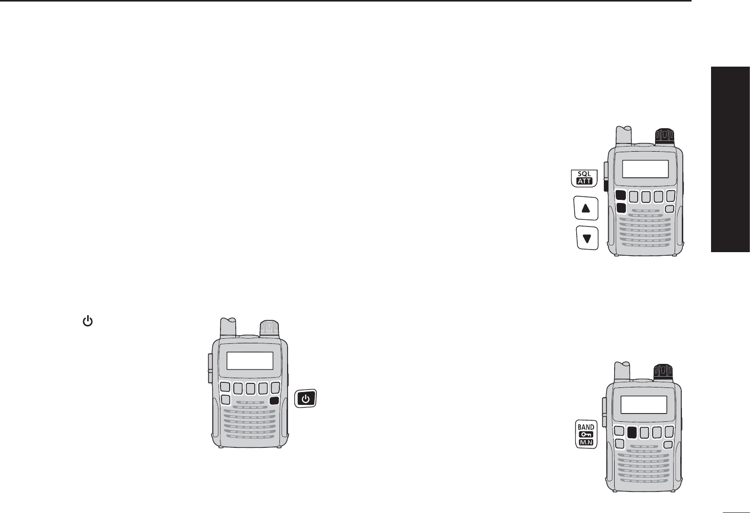
DBasic operation
1. Turning ON the receiver
±Hold down [ ] for 1 second to
turn the power ON.
2. Adjusting audio level
±Push [S]/[T] to set a desired
audio level.
3. Adjusting squelch level
±While holding down [SQL],
rotate [DIAL] to set the squelch
level.
4. Setting a desired frequency
The tuning dial will allow you to dial in the frequency you
want to listen to. Pages 9 and 15 will instruct you on how to
set the tuning speed.
q Push [BAND] repeatedly to
select a frequency band.
• Holding down [BAND], rotating
[DIAL] will also select a frequency
band.
w Rotate [DIAL] to set the receive
frequency.
•
While holding down [FUNC], rotate
[DIAL] to select frequencies in 1
MHz steps.
N Your first scanning experience
[DIAL]
[DIAL]
IV
QUICK REFERENCE GUIDE
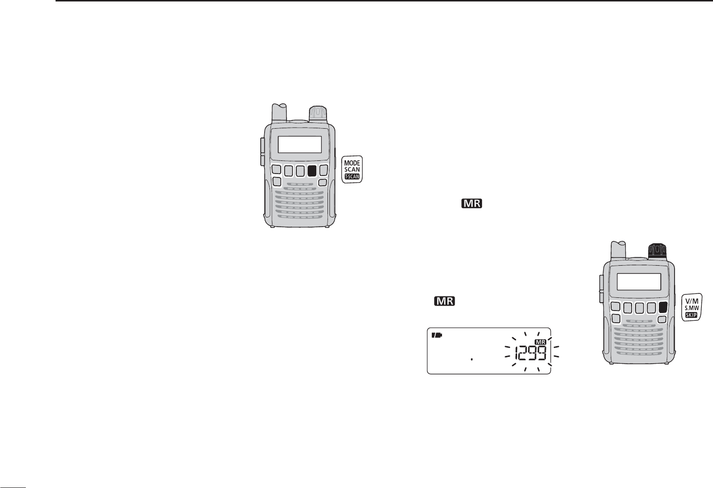
N Your first scanning experience (continued)
5. Receive mode selection
±Push [MODE] repeatedly to
select a desired receive mode.
• The FM, WFM or AM is selectable.
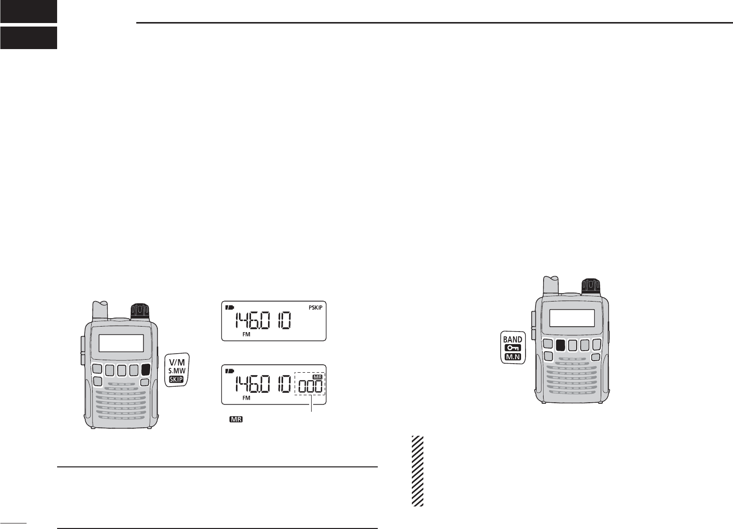
N Memory programming
The IC-R6 has a total of 1300 memory channels for stor-
ing often used receive frequency, mode, etc. The memory
channels include 200 auto write channels and 50 scan edge
channels.
1. Setting frequency
In the VFO mode, set a desired receive frequency mode.
• When the “ ” icon is displayed, push [V/M] to select the VFO
mode.
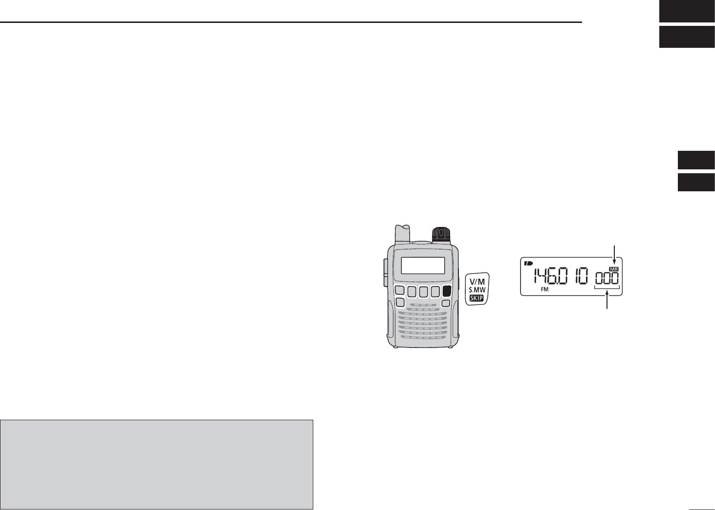
2. Selecting a memory channel
Hold down [S.MW](V/M) for
1 second, then rotate [DIAL] to
select a desired memory channel.
• The “ ” icon and memory chan-
nel number blink.
3. Writing a memory channel
Hold down [S.MW](V/M) for 1 second until 3 beeps sound.
• The memory channel number automatically increases when hold-
ing down [S.MW](V/M,) after programming.
[DIAL]
V
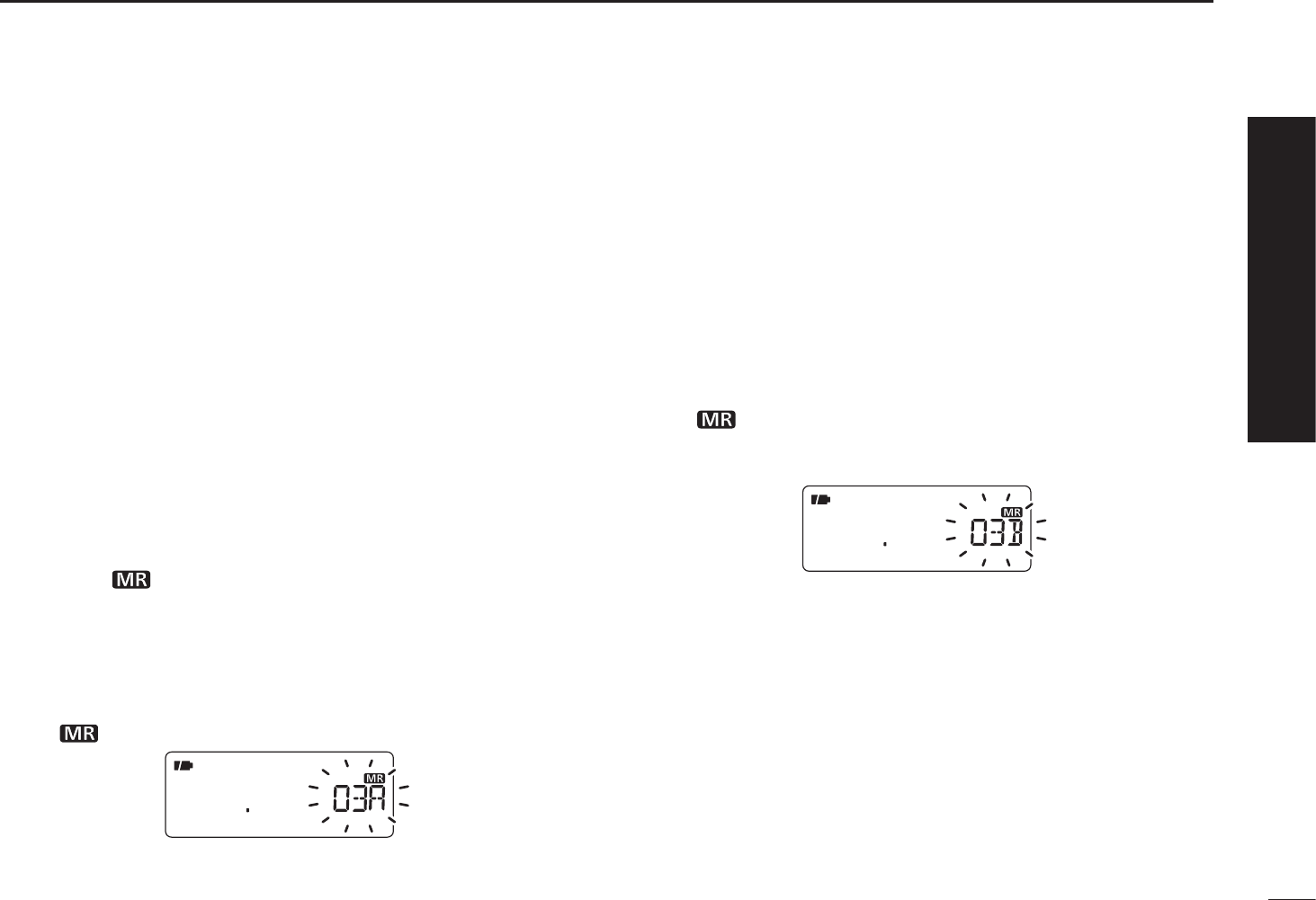
QUICK REFERENCE GUIDE
N Programmed scan operation
25 pairs, 50 channels of memories are used for programmed
scan operation, that specifies a scanning ranges. The pro-
grammed scan scans between “xxA” and “xxB” (xx=00 to 24)
frequencies. Therefore, before operating the programmed
scan, different frequencies must be programmed into “A” and
“B” scan edge channels.
D Programming scan edges
A start frequency must be programmed into a “xxA,” and end
frequency must be programmed into a “xxB” memory chan-
nel.
1. Setting frequency
In the VFO mode, set a desired receive frequency selection
mode.
• When the “ ” icon is displayed, push [V/M] to select the VFO
mode.
2. Selecting a scan edge “A” channel
Hold down [S.MW](V/M)
for 1 second,
then rotate [DIAL] to
select one of the 25 scan edge “A” channels.
• The “ ” icon and scan edge channel number blink.
3. Writing a memory channel
Hold down [S.MW](V/M) for 1 second until 3 beeps sound.
• The paired scan edge “B” channel is automatically selected when
holding down [S.MW](V/M) after programming.
• When programming is completed, return to the VFO mode.
4. Selecting a scan edge “B” channel
Hold down [S.MW](V/M)
for 1 second,
then rotate [DIAL] to
select one of the 25 scan edge channel “B.”
• The “ ” icon and the scan edge channel number blink.
• When the scan edge “B” channel is already selected in step 3. (by
holding down [S.MW](V/M) after programming), skip this step.
5. Writing a memory channel
Hold down [S.MW](V/M) for 1 second until 3 beeps sound.
• The next scan edge “A” channel is automatically selected when
holding down [S.MW](V/M) after programming.
• When programming is completed, return to the VFO mode.
Quick reference guide
VI
QUICK REFERENCE GUIDE
D Starting scan
1. Select the VFO mode.
Push [V/M] to select the VFO mode for a VFO scan opera-
tion, such as full scan, band scan and programmed scan.
• Select the memory mode by pushing [V/M] again for a memory
scan operation, such as all memory scan, bank link scan or bank
scan.
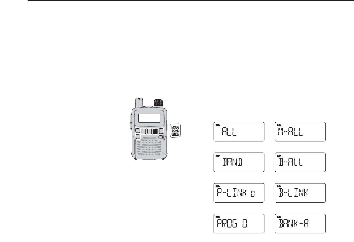
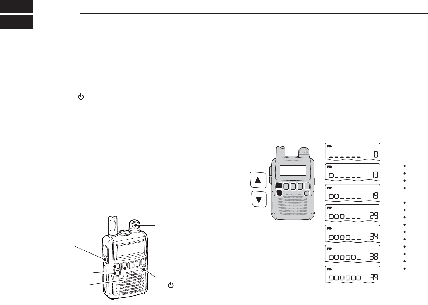
2. Selecting a scan type
Hold down
[SCAN](MODE) for
1 second, and
then rotate [DIAL]
to select one of a desired scanning
types.
• Select “ALL” for full scan, “BAND” for
band scan, “P-LINK x” for programmed
link scan (x= 0 to 9), “PROGxx” for
programmed scan (xx= 0 to 24; only
programmed scan edge numbers are
displayed).
• Select “M-ALL” for all memory scan,
“B-ALL” for all bank scan, “B-LINK” for
bank link scan or “BANK-x” for bank
scan (x= A to R, T, U, W, Y; only pro-
grammed bank groups are displayed).
• Full scan
• Band scan
• Program link scan
• Program scan
• All memory scan
• All bank scan
• Bank link scan
• Bank scan
Scan type display examples
In the VFO mode In the memory mode
VII
QUICK REFERENCE GUIDE
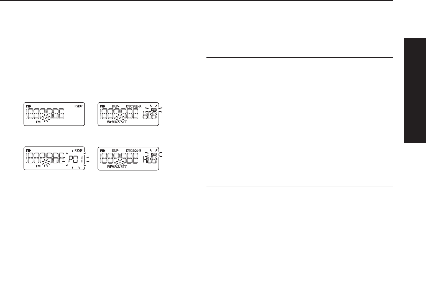
3. Starting scan
Push
[SCAN](MODE)
to start the scan.
• Rotate [DIAL] to change the scanning direction.
• Full/Band scan
• Program link
Program scan
• All memory/All bank
bank link scan
• Bank scan
In the VFO mode In the memory mode
4. Cancelling scan
Push
[SCAN](MODE)
again to stop the scan.
For your information
The memory channel number you program the scan edges
into correlates “PROGxx” as follows:
00A/00B: Selects “PROG 00” to scan between frequencies
programmed in channels 00A and 00B.
01A/01B: Selects “PROG 01” to scan between frequencies
programmed in channels 01A and 01B.
•
•
•
•
23A/23B: Selects “PROG 23” to scan between frequencies
programmed in channels 23A and 23B.
24A/24B: Selects “PROG 24” to scan between frequencies
programmed in channels 24A and 24B.
Quick reference guide
1
PANEL DESCRIPTION
1
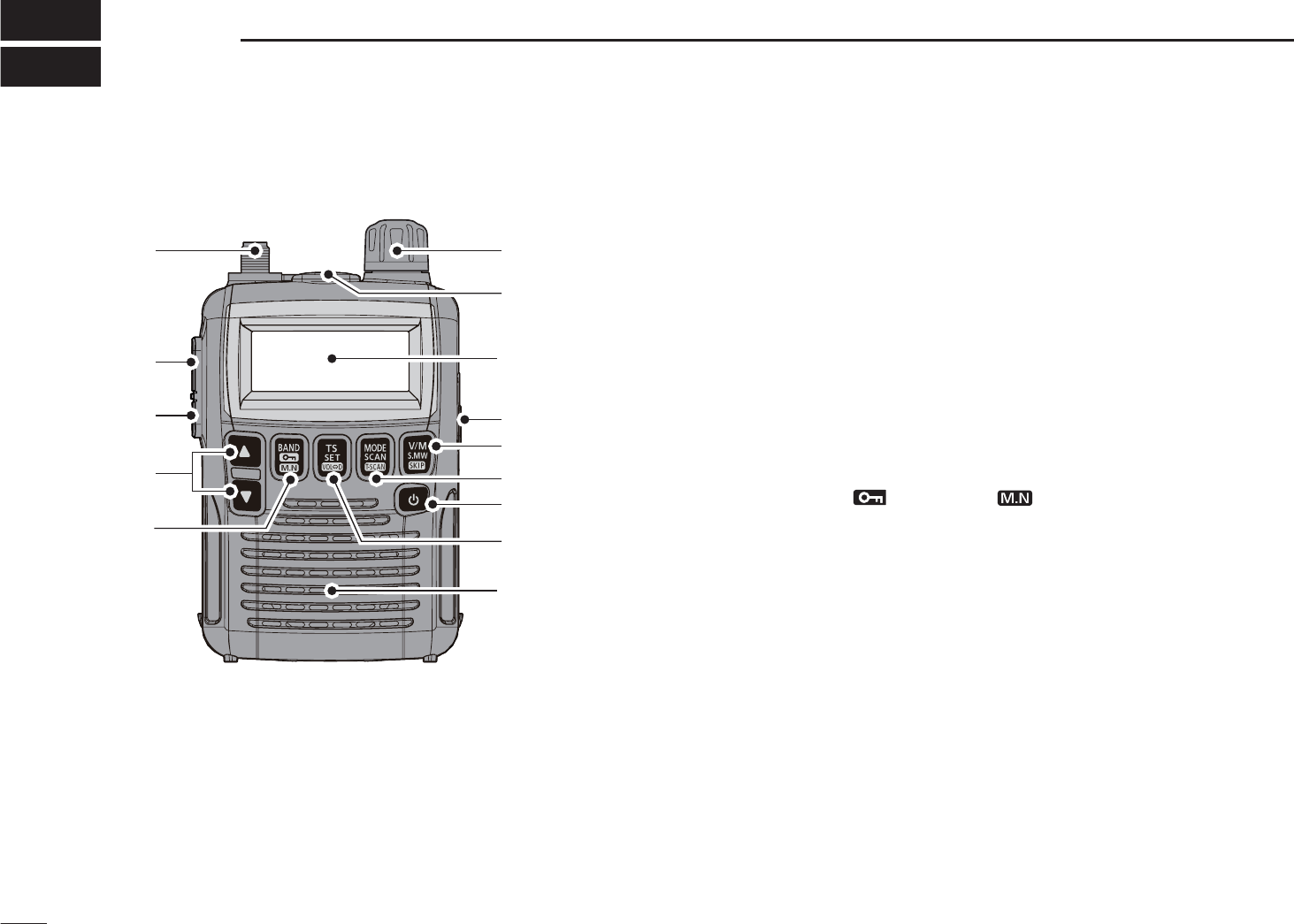
N Front, top and side panels
!2
!0
u
t
r
e
w
!1
q
Function display
(pp 3, 4)
Speaker
o
i
y
qANTENNA CONNECTOR (p. I)
Connect the supplied antenna.
• An optional AD-92SMA is available for connecting an antenna
with a BNC connector.
wFUNCTION KEY [FUNC]
While holding down this switch, access a key’s secondary
or third function.
eSQUELCH • ATTENUATOR KEY [SQL] • [ATT](SQL)
±Hold down to temporarily open the squelch and moni-
tor the operating frequency. (p. 13)
±While holding down this switch, rotate [DIAL]* to adjust
the squelch level. (p. 12)
±While holding down [FUNC], push to toggle the attenu-
ator function ON or OFF. (p. 10)
rUP/DOWN KEYS [S]/[T]*
Adjusts the audio volume level. (p. 11)
t BAND • LOCK • MEMORY NAME KEY
[BAND] • [ ](BAND) • [ ](BAND)
± Push to select the operating frequency band. (p. 7)
±While holding down [FUNC], push and hold for
1 second to toggle the lock function ON or OFF. (p. 10)
±During memory mode operation, hold down [FUNC],
then push this key to select the display type.
• The display shows the memory bank name†, memory name†
and channel number in sequence, and then returns to the
frequency display.
†The memory bank name or memory name must have pre-
programmed.
*The functions of [DIAL] and [S]/[T] can be exchanged. See page
49 for details.

2
1
PANEL DESCRIPTION
1
2
3
4
5
6
7
8
9
10
11
12
13
14
15
16
y TUNING STEP • SET • DIAL EXCHANGE KEY
[TS] • [SET](TS) • [ ](TS)]
± Push to enter tuning step selecting mode. (p. 9)
± Hold down for 1 second to enter the Set mode. (p. 39)
±While holding down [FUNC], push to exchange the
[DIAL] and [S]/[T] keys’ functions. (p. 49)
uPOWER KEY [ ]
Hold down for 1 second to turn the receiver power ON or
OFF.
i MODE • SCAN • TONE SCAN KEY
[MODE] • [SCAN](MODE) • [ ](MODE)
± Push to select the receive mode. (p. 12)
±Hold down for 1 second to enter the scan type selec-
tion mode. (p. 26)
• Push again to start the scan.
±While holding down [FUNC], push to start a tone scan.
(p. 38)
o VFO/MEMORY • MEMORY WRITE • SKIP KEY
[V/M] • [S.MW](V/M) • [ ](V/M)
± Toggles between the VFO or the memory mode. (p. 7)
±Hold down for 1 second to enter memory edit condi-
tion. (p. 16)
±During VFO mode operation, hold down [FUNC], then
push this key to select the programmed skip scan set-
ting ON or OFF.
±During memory mode operation, hold down [FUNC],
then push this key to select the scan skip condition for
the selected channel. (p. 30)
!0EXTERNAL DC-IN CONNECTOR [DC4.5V] (p. 6)
Connects an AC adapter or an optional cigarette lighter
cable for both charging the installed re-chargeable battery
and operating. Connectable voltage is from 4.5 V DC to
6.3 V DC.
!1EXTERNAL SPEAKER CONNECTOR [SP]
Connect an optional earphone or headphones.
The internal speaker will not function when any external
equipment is connected. (See page 65 for a list of avail-
able options.)
!2CONTROL DIAL [DIAL]*
± Rotate to select the operating frequency.* (p. 9)
±While scanning, changes the scanning direction.
(p. 26)
±While holding down [SQL], sets the squelch level.
(p. 12)
±While holding down [FUNC], sets the operating fre-
quency in 100 kHz, 1 MHz or 10 MHz in the VFO
mode. (p. 9)
±While holding down [FUNC], selects the memory chan-
nel in 10 channels steps in the memory mode. (p. 10)
±While holding down [BAND], selects the operating
band in the VFO mode. (p. 7)
*The functions of [DIAL] and [S]/[T] can be exchanged. See page
49 for details.
3
1PANEL DESCRIPTION
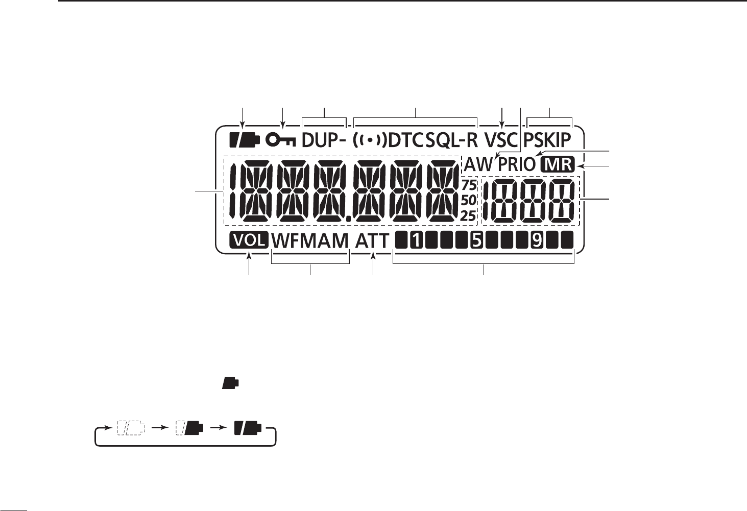
qBATTERY ICON
±Both segments appear when the batteries have ample
capacity.
• They do not appear when operating with an external power
source.
±Only the right segment “ ” appears when the batter-
ies have less than half capacity.
±Scrolls while charging the rechargeable batteries. (p. 6)
±Both segments blink when completely charged.
wLOCK ICON (p. 10)
Appears when the lock function is activated.
eDUPLEX ICONS (p. 14)
“DUP” appears when plus duplex, and “DUP–” appears
when minus duplex operation is selected.
rTONE ICONS
±“T SQL” appears while the tone squelch function is in
use. (p. 35)
±“DTCS” appears while the DTCS squelch function is in
use. (p. 35)
±“S” appears with the “T SQL” or “DTCS” icon while
the pocket beep function (with CTCSS or DTCS) is in use.
(p. 35)
tVSC ICON (p. ??)
Appears while the VSC function is in use.
N Function display
q
!5
!3 !2
o
i
!1
!0
!4
we yrtu

4
1
PANEL DESCRIPTION
1
yAUTO WRITE CHANNEL ICON (p. 29)
Appears when an auto write channel is selected.
uSKIP ICONS (p. 30)
±“SKIP” appears when the selected memory channel is
specified as a skip channel.
±“PSKIP” appears when the displayed frequency is
specified as a skip frequency.
iPRIORITY WATCH ICON (p. 33)
Appears while priority watch is in use.
oMEMORY ICON (pgs. 7, 10)
Appears when the memory mode is selected.
!0MEMORY CHANNEL NUMBER
Shows the selected memory channel number. (pgs. 7, 10)
!1SIGNAL STRENGTH INDICATOR (p. 11)
Shows the relative signal strength while receiving signals.
!2ATTENUATOR ICON (p. 13)
Appears while the RF attenuator is in use.
!3RECEIVE MODE ICON (p. 12)
Shows the selected receive mode.
• FM, WFM and AM modes are selectable.
!4VOLUME EXCHANGE ICON (p. 49)
Appears when the function of [DIAL] and [S]/[T] are
exchanged.
!5FREQUENCY READOUT
Shows a variety of information, such as the operating fre-
quency, Set mode contents, memory names.
• The smaller “75,” “50” and “25” to the right of the readout indi-
cate 0.75, 0.5 and 0.25 kHz, respectively.
• The decimal point blinks during a scan.
5
BATTERY CHARGING
2
N Battery installation
Before installing, or replacing the batteries, hold down [ ]
for 1 second to turn the power OFF.
q Remove the battery cover from the receiver.
Latch
w Install 2 R6 (AA) size Ni-MH batteries.
• Be sure to observe the correct polarity.
N Caution
•R DANGER! NEVER short the battery terminals (or charg-
ing terminals). Also, current may flow into nearby metal
objects such as a necklace, so be careful when placing
batteries (or the receiver) in handbags, etc.
Simply carrying with or placing near metal objects such as
a necklace, etc. may cause shorting. This may damage not
only the batteries, but also the receiver.
•R DANGER! NEVER incinerate used batteries. Internal
battery gas may cause an explosion.
•R DANGER! NEVER immerse the batteries in water. If the
batteries become wet, be sure to wipe them dry BEFORE
installing them to the receiver.
• When installing batteries, make sure they are all the same
brand, type and capacity. Also, do not mix new and old bat-
teries together.
• Never use batteries whose insulated covering is damaged.
•Keep battery terminals clean to avoid rust or misscontact.
It’s a good idea to clean battery terminals once a week.
D Caution for the Ni-MH batteries
•CAUTION: Always use the batteries within the speci-
fied temperature range, –5˚C to +60˚C (+23˚F to +140˚F).
Using the batteries out of their specified temperature range
will reduce the battery’s performance and battery life.

6
2
BATTERY CHARGING
2
•CAUTION: Shorter battery life could occur if the batteries
are left completely discharged, or in an excessive temper-
ature environment (above +55˚C; +131˚F) for an extended
period of time. If the batteries must be left unused for a
long time, they must be detached from the receiver after
charging. Keep them safely in a cool dry place at the fol-
lowing temperature range:
–20˚C to +45˚C (–4˚F to +113˚F) (up to a month)
–20˚C to +35˚C (–4˚F to +95˚F) (up to six months)
–20˚C to +25˚C (–4˚F to +77˚F) (up to a year*)
* We recommend charging the batteries every 6 months.
• If your Ni-MH batteries seem to have no capacity, even
after being charged, completely discharge them by leaving
the power ON overnight. Then, fully charge the batteries
again. If the batteries still do not retain a charge (or only
very little charge), a new batteries must be purchased.
Prior to using the receiver for the first time, the batteries
must be fully charged for optimum life and operation.
• The supplied batteries are rechargeable batteries.
Charge the batteries before first operating the receiver, or
when the batteries become exhausted.
If you want to prolong the battery life, the following points
should be observed:
- Avoid over charging.
- Use the batteries until it becomes almost completely ex-
hausted, under normal conditions.
D Charging caution
•RWARNING! NEVER charge alkaline batteries.
The receiver can charge only the Ni-MH batteries (1.2 V,
1400 mAH typ.). Other types of rechargeable battery, such
as Ni-Cd or Li-Ion cannot be charged.
•AVOID over charging— The installed rechargeable batter-
ies can be charged during operation when the AC adapter
or the cigarette lighter cable is connected. To prevent over
charging, the IC-R6 has charging timer that automatically
disconnecting* the charging line electronically after 15 hours
from charging. However, the charging timer will reset and
start charging again when disconnect then reconnecting the
AC adapter or CP-18A/E more than 1 minute interval.
* When the “CHARGE” setting in the Set mode is set to “CHG2,”
the receiver continues to trickle charge after 15 hours have past.
• Recommended temperature range for charging:
between 0°C (+32˚F) and +40°C (+140˚F) by the receiver.
• Use the BC-196S/BC-153SC AC adapter or CP-18A/E cig-
arette liter cable only. NEVER use other manufacturers’
chargers.
• The external DC power supply voltage must be between
12–16 V to charge the batteries and for operation when
using an optional CP-18A/E.
• If the battery icons (“ ” and “ ”) disappear only
1 minute after connecting to the DC power supply, the bat-
teries may have problem. In this case, contact your Icom
dealer/distributor, or purchase a new batteries.
7
2BATTERY CHARGING
N Battery charging
D Charging connections
IC-R6
CP-18A/E
Cigarette lighter cable
with DC-DC converter
AC adapter
to a cigarette
lighter socket
The shape may
differ depending
on the version.
to an AC outlet
to the [DC4.5V]
jack
• Charging periods: Approx. 15 hours
RWARNING!:
NEVER attempt to charge the alkaline batteries.
CAUTION: BE SURE to disconnect the CP-18A/E from
the cigarette lighter socket when charging is finished, be-
cause, a slight current still follows in the CP-18A/E and
the vehicle’s battery will become exhausted.
D Charging description
qInstall the Ni-MH batteries. (See page 5.)
w Plug the AC adapter into an AC outlet; or the CP-18A/E
into a cigarette lighter socket.
eInsert the adapter plug into [DC4.5V] of the receiver.
• Once the batteries are removed for more then 2 seconds, the
following operations are necessary.
• The battery confirmation is displayed.
If the confirmation does not appear, following operation
is necessary.
q Disconnect the adapter plug from [DC4.5V].
w Holding down [FUNC], insert the adapter plug again.
e Release [FUNC].
r Rotate [DIAL] to select “Y,” then push [BAND].
[DIAL]
8
2
BATTERY CHARGING
1
2
3
4
5
6
7
8
9
10
11
12
13
14
15
16
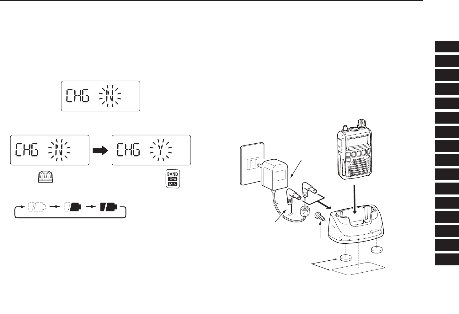
• The charging confirmation is displayed.
uRotate [DIAL] to select “Y,” then push [BAND] to start the
battery charging.
Rotate Then, push
• The battery icon scrolls during charge.
• Both segments blink when completely charged.
• It takes approximately 13 hours to fully charge the Ni-MH bat-
teries.
D Charge adapter BC-194
The BC-194, charge adapter, is useful to charge, and the
receiver is easy to attach to or detach from the BC-194.
The BC-194 can be used the BC-196S/BC-153SC or
CP-18A/E to a power source.
Receiver
BC-194
CP-18A/E
cigarette lighter cable
AC adapter
(supplie with receiver)
Double-sided tape
(with BC-194)
Ground screw
(with BC-194)
9
FREQUENCY AND CHANNEL SETTING
3
N VFO and memory channels
The IC-R6 has 2 normal operating modes: the VFO mode
and the memory mode.
The VFO mode is used for a desired frequency setting
within the frequency coverage.
± Push [V/M] to select the VFO mode.
The memory mode is used for quick recall the
preprogrammed memory channels.
± Push [V/M] to select the memory mode.
• See p. 16 for memory programming details.
[DIAL]
“ ” and memory channel
number appear.
• VFO mode display
• Memory mode display
What is VFO?
VFO is an abbreviation of Variable Frequency Oscillator.
Operating frequencies are generated and controlled by the
VFO.
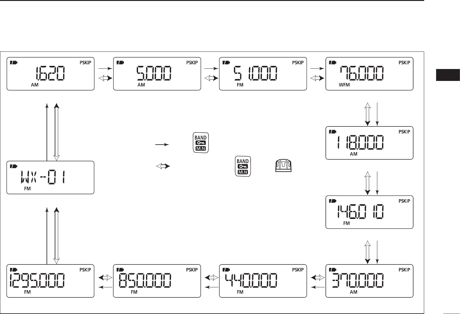
N Operating band selection
The receiver can receive the AM broadcast, HF band, 50 MHz,
FM broadcast, VHF air, 144 MHz, 300 MHz, 400 MHz, 800
MHz,* 1200 MHz, television channels or Weather channels†.
±Push [BAND] repeatedly to select a desired frequency
band.
• When the memory mode is selected, push [V/M] to select the
VFO mode first, then push [BAND] to select a desired band.
±While holding down [BAND], rotating [DIAL] also selects
frequency band.
[DIAL]
Available frequency bands are differ depending on ver-
sion. See the specification for details.
*Some frequency ranges are inhibited for the USA version
due to local regulation.
†Available in only the USA version.
10
3
FREQUENCY AND CHANNEL SETTING
3
• Available frequency bands
AM broadcast band HF band 50 MHz band
800 MHz band 400 MHz band
FM broadcast band
VHF air band
144 MHz band
300 MHz band
Weather channels*
1200 MHz band
: Push
: While holding down , rotate
The actual frequencies may differ, depending on your receiver version.
*Available in only the USA version
11
3FREQUENCY AND CHANNEL SETTING
N Setting a frequency
qPush [V/M] to select the VFO mode, if necessary.
wSelect a desired frequency band with [BAND].
• Or, while holding down [BAND], rotate the [DIAL] to select a
desired frequency band.
eRotate [DIAL] to select a desired frequency band.
• The frequency changes according to the preset tuning steps.
See the section to the right for setting the tuning step.
• While holding down [FUNC], rotate [DIAL] to change the fre-
quency in 1 MHz steps (default).
[DIAL]
[DIAL] changes the
frequency according to
the selected tuning step.
While continuing to push
[FUNC], [DIAL] changes
the frequency in 1 MHz
steps (default).
The 1 MHz tuning step (dial select step) can be set to 100
kHz, 1 MHz or 10 MHz tuning steps in the Set mode. See
p. 15 for details.
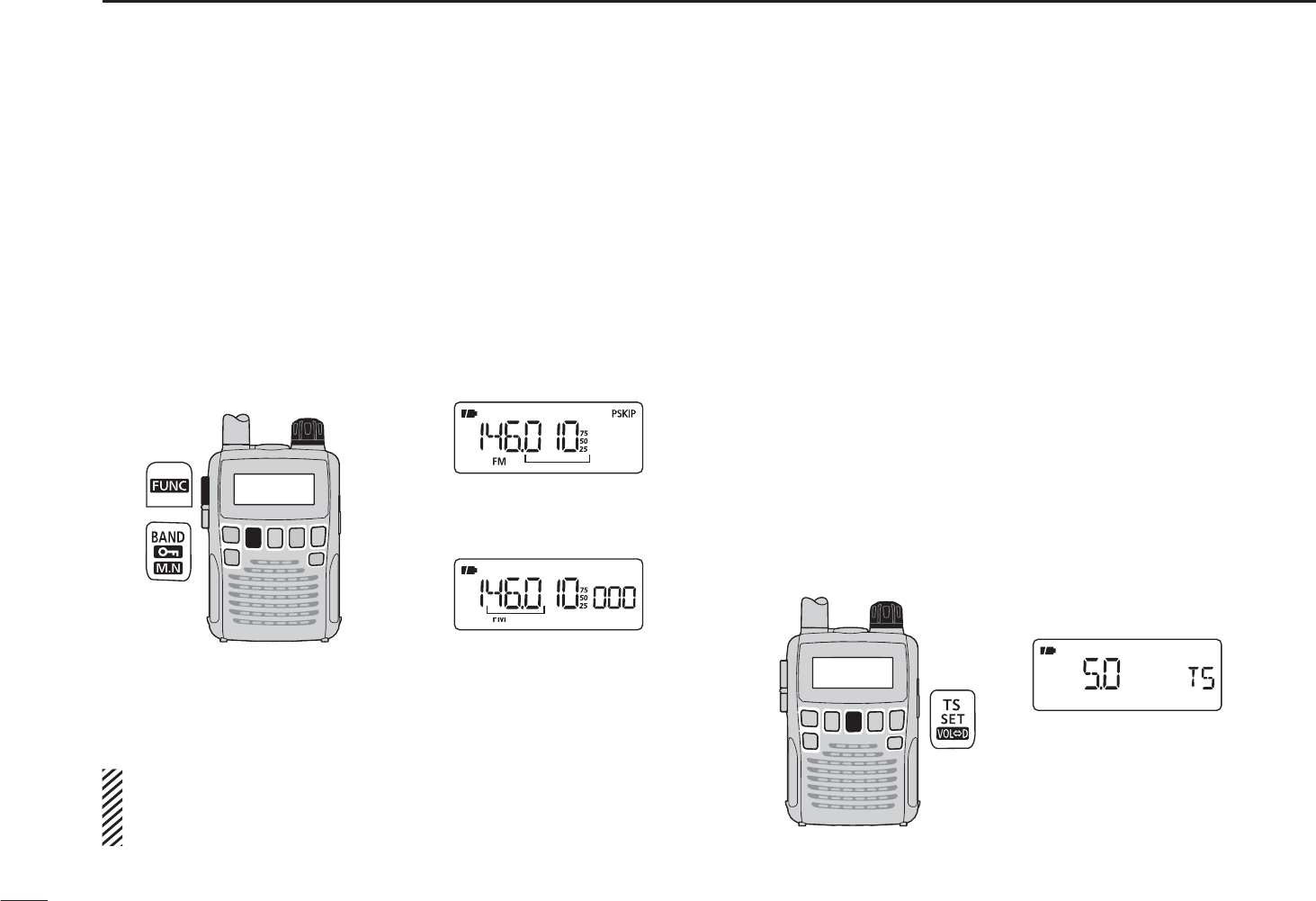
NSetting a tuning step
The tuning step can be selected for each frequency band.
However, additional steps become selectable only in theadditional steps become selectable only in the
VHF Air band (8.33 kHz) and in the AM broadcast band (9
kHz)*. The following tuning steps are available for the IC-R6.The following tuning steps are available for the IC-R6.
• 5.0 kHz • 6.25 kHz • 8.33 kHz* • 9.0 kHz*
• 10.0 kHz • 12.5 kHz • 15.0 kHz • 20.0 kHz
• 25.0 kHz • 30.0 kHz • 50.0 kHz • 100.0 kHz
D Tuning step selection
qPush [V/M] to select the VFO mode, if necessary.
wPush [BAND] to select a desired frequency band.
• Or, while holding down [BAND], rotate [DIAL] to select a
desired frequency band.
ePush [TS] to enter tuning step selecting condition.
rRotate [DIAL] to select a desired tuning step.
tPush [TS] to return to the VFO mode.
[DIAL]
5 kHz tuning step
12
3
FREQUENCY AND CHANNEL SETTING
3
N Selecting a memory channel
qPush [V/M] to select the memory mode.
• “ ” appears when the memory mode is selected.
wRotate [DIAL] to select a desired memory channel.
• Only programmed memory channels can be selected.
• While holding down [FUNC], rotate [DIAL] to select a memory
channel in 10 channels steps.
[DIAL]
[DIAL] changes the
memory channel.
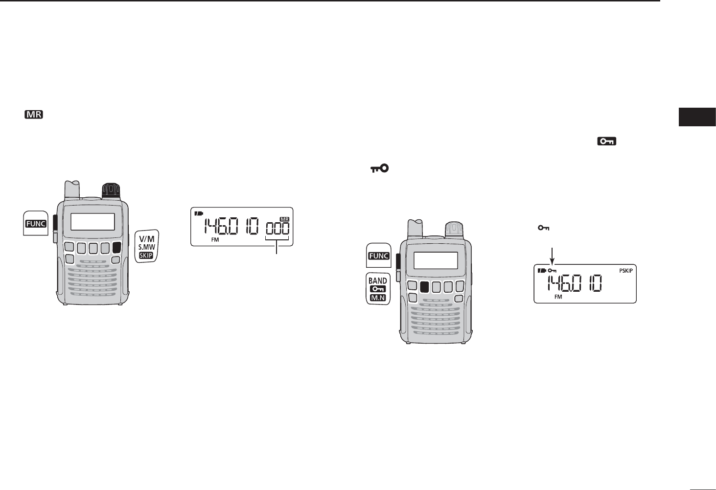
N Lock function
To prevent accidental frequency changes and unnecessary
function access, use the lock function.
±While holding down [FUNC], push and hold [ ](BAND)
for 1 second to turn the lock function ON or OFF.
• “ ” appears while the lock function is activated.
•[SQL] and [S]/[T] can be used while the lock function is in use
with default setting. Either or both [SQL] and [S]/[T] keys can
also be locked in the Set mode. (p. 43)
“ ” appears while the
lock function is in use.
13
BASIC OPERATION
4
N Receiving
Make sure charged Ni-MH or brand new alkaline batteries
are installed (p. 5).
qHold down [] for 1 second to turn power ON.
wPush
[S]
or
[T]
to set a desired audio level.
• The function display shows the volume level while setting. See
the section to the right for details.
eSet the receive frequency. (p. 9)
rSet the squelch level. (p. 12)
• While holding down [SQL], rotate [DIAL].
• The first click of [DIAL] indicates the current squelch level.
• “LEVEL 1” is loose squelch and “LEVEL 9” is tight squelch.
• “AUTO” indicates automatic level adjustment with a noise pulse
count system.
• Hold down [SQL] to open the squelch manually.
t When a signal is received:
• Squelch opens and audio is heard.
• The S-meter shows the relative signal strength.
qPower ON
[ ]
e Set frequency
r Set squelch level
w Set audio level
e Select band
r Push for setting
the squelch
(Push to monitor)
NSetting audio volume
The audio level can be adjusted through 40 levels.
±P
ush [S] or [T] to adjust the audio level.
• A beep tone sounds while adjusting. The tone sound let you
know the approximate sound level.
• Holding down either key will continuously change the audio
level.
• The display shows the volume level while setting.
AUDIO LEVEL
Minimum level
(no audio)
Maximum level
Initial setting
DISPLAY
14
4
BASIC OPERATION
4
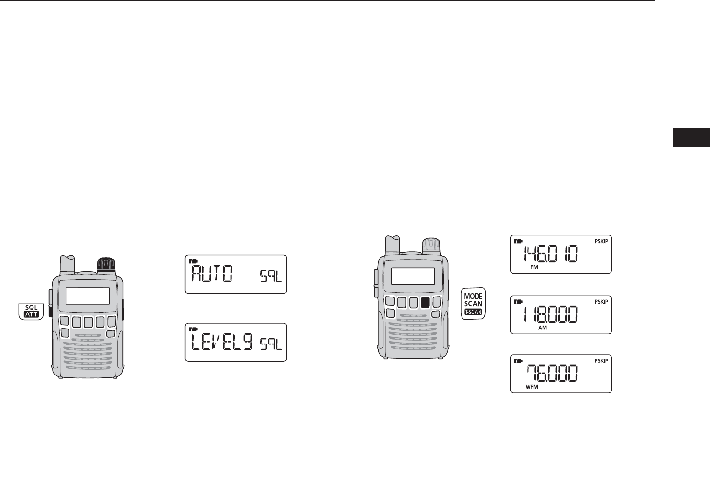
N Squelch level setting
The squelch circuit mutes the received audio signal, depend-
ing on the signal strength. The receiver has 9 squelch levels,
a continuously open setting and an automatic squelch set-
ting.
±While holding down [SQL], rotate [DIAL] to select the
squelch level.
• “LEVEL 1” is loose squelch (for weak signals) and “LEVEL 9” is
tight squelch (for strong signals).
• “AUTO” indicates the automatic level adjustment by a noise
pulse count system.
• “OPEN” indicates the continuously open setting.
[DIAL]
Automatic squelch
Maximum level
N Receive mode selection
The receiver has three receive modes, FM, AM and WFM.
The mode selection is stored independently in each band
and memory channels.
Typically, the AM mode is used for the AM broadcast stations
(0.495–1.620 MHz) and air band (118–135.995 MHz), and
WFM is used for FM broadcast stations (76–107.9 MHz).
±Push [MODE] repeatedly to select a desired receive
mode.
FM mode
AM mode
WFM mode
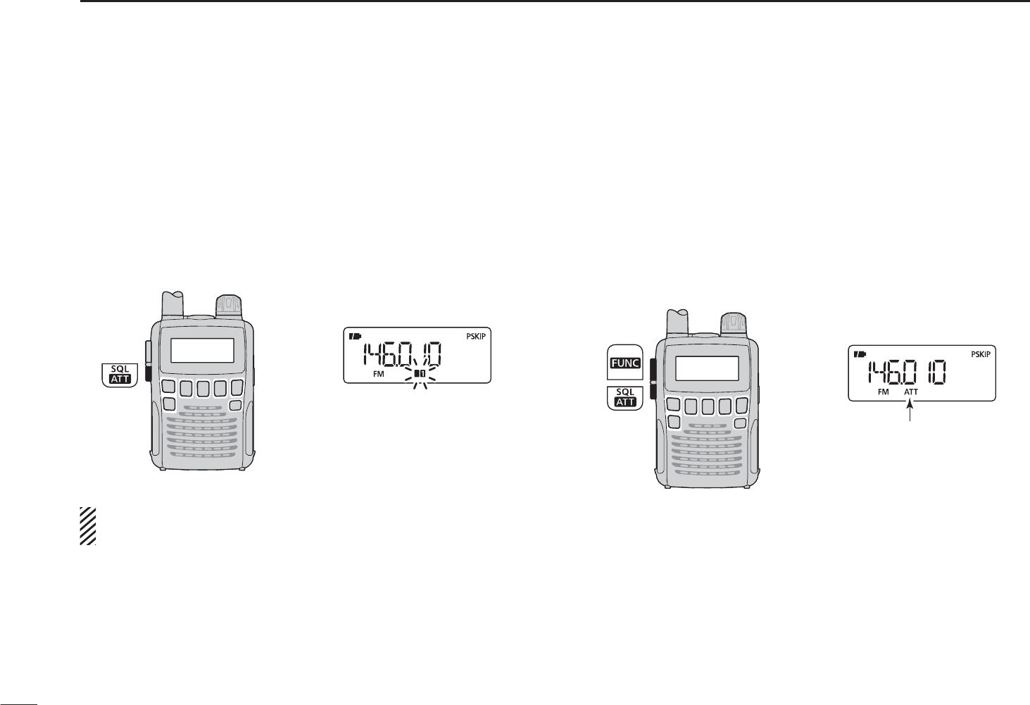
N Monitor function
This function is used to listen to weak signals, without dis-
turbing the squelch setting. It can also be used to open the
squelch manually, even when mute functions such as the
tone squelch are in use.
± Hold down [SQL] to monitor the receive frequency.
• The 1st segment of the S-meter blinks.
The 1st/2nd segments blink
The [SQL] switch can be set to a ‘sticky’ operation in the
Expand set mode. See page 43 for details.
N Attenuator function
The attenuator prevents a received signal from distorting
when very strong signals are near a desired frequency, or
when very strong electric fields, such as from a broadcasting
station, are near your location.
±
While holding down [FUNC], push [ATT](SQL) to toggle
the attenuator function ON or OFF.
• “ATT” appears when the attenuator functions is in use.
“ATT” appears while the
attenuator functions is in
use.
15
4BASIC OPERATION
16
4
BASIC OPERATION
4
Duplex communication uses 2 different frequencies for trans-
mitting and receiving. Generally, duplex is used in communi-
cation through a repeater, some utility communications, etc.
During duplex operation, the transmit station frequency is
shifted from the receive station frequency by the offset fre-
quency. Repeater information (offset frequency and shift di-
rection) can be programmed into memory channels. (p. 16)
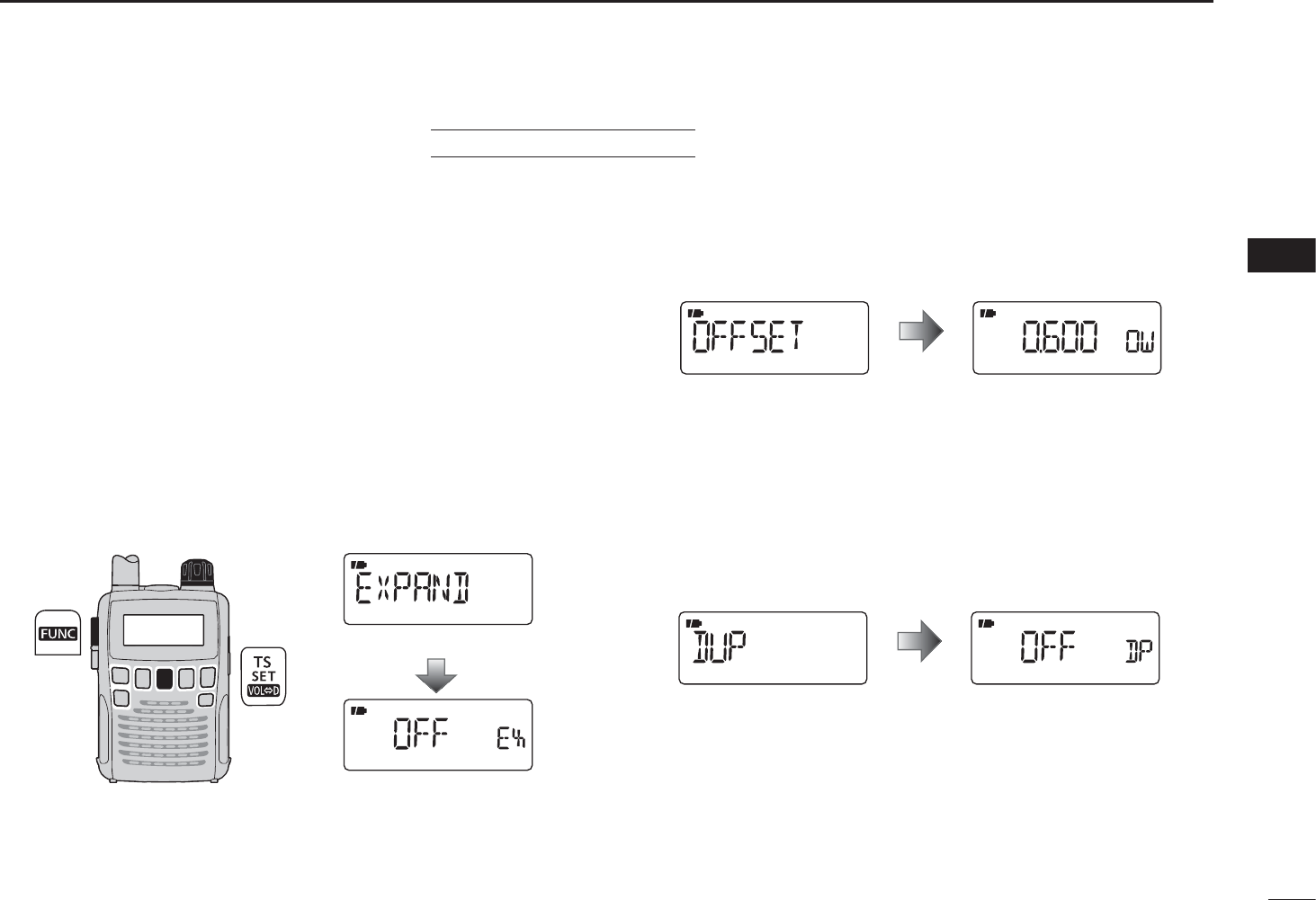
D Setting
q
Set the receive station frequency
(repeater output frequency)
.
wHold down [SET](TS) for 1 second to enter the Set mode.
eRotate [DIAL] to select the “EXPAND” item.
• “EXPAND” disappears after 1 second and “OFF” (default) and
“EX” appear.
[DIAL]
Expanded set mode item
Setting display
r While holding down [FUNC], rotate [DIAL] to select “ON.”
tRotate [DIAL] to select the “OFFSET” item.
• “OFFSET” disappears after 1 second and “0.600” (default) and
“OW” appear.
(Default offset differs depending on the frequency band or
receiver version.)
Frequency offset item Setting display
After 1 sec.
y While holding down [FUNC], rotate [DIAL] to set a
desired offset frequency within 0.000–159.995 MHz
range.
• The tuning step, selected in the VFO mode, is used for setting.
uRotate [DIAL] to select the “DUP” item.
• “DUP” disappears after 1 second and “OFF” (default) and “DP”
appear.
Duplex item Setting indication
After 1 sec.
i While holding down [FUNC], rotate [DIAL] to select “–
DUP” or “+DUP.”
oPush [SET](TS) to exit the Set mode.
!0 Hold down [SQL] to monitor the transmit station frequen-
cy (repeater input frequency) directly.
NDuplex operation USING EXPAND SET MODE
17
4BASIC OPERATION
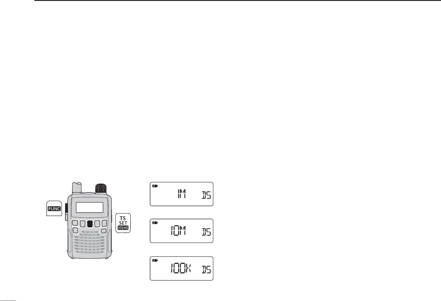
N Dial select step [
This receiver has a 1 MHz tuning step for quick frequency
setting. You can select 100 kHz, 1 MHz or 10 MHz steps, as
desired.
D Setting dial select step
qPush [V/M] to select the VFO mode.
wHold down [SET](TS) for 1 second to enter the Set mode.
eRotate [DIAL] to select the “D SEL” item.
• “D SEL” disappears after 1 second and “1M” (default) and “DS”
appear.
r While holding down [FUNC], rotate [DIAL] to select a
desired dial select step.
• 100 kHz, 1 MHz and 10 MHz can be selected.
tPush [SET](TS) to exit the Set mode.
[DIAL]
1 MHz step
10 MHz step
100 kHz step
18
5
MEMORY CHANNELS
4
5
N General description
The receiver has 1350 memory channels, including 50 scan
edge memory channels (25 pairs) for storage of often-used
frequencies. A total of 18 memory banks, A to R, T, U, W and
Y can be selected. Up to 100 channels can be assigned to
each bank.
D Memory channel contents
The following information can be programmed into memory
channels:
• Receive frequency (p. 9)
• Receive mode (p. 12)
• Duplex direction (+DUP or –DUP) with a frequency offset
(p. 14)
• Tone squelch or DTCS squelch ON/OFF (p. 35)
• Tone squelch frequency or DTCS code with polarity (pp.
36, 37)
• Scan skip setting (p. 30)
• Memory bank (p. 95)
• Memory name (p. 97)
• Tuning step (p. 22)
N Selecting a memory channel
q Push [V/M] to select the memory mode.
• Push [V/M] to toggle between the VFO mode and the memory
channel mode.
w Rotate [DIAL] to select a desired memory channel.
• Only programmed channels are displayed.
• While holding down [FUNC], rotate [DIAL] to select the memory
channel in 10 channel steps.
Appears
Rotate [DIAL] to select
the memory channel.
NOTE: Memory data can be erased by static electricity,
electric transients, etc.
In addition, it can be erased by malfunction and during
repairs. Therefore, we recommend that memory data be
written down or saved to a PC using the CS-R6 CLONING
SOFTWARE.
19
5MEMORY CHANNELS
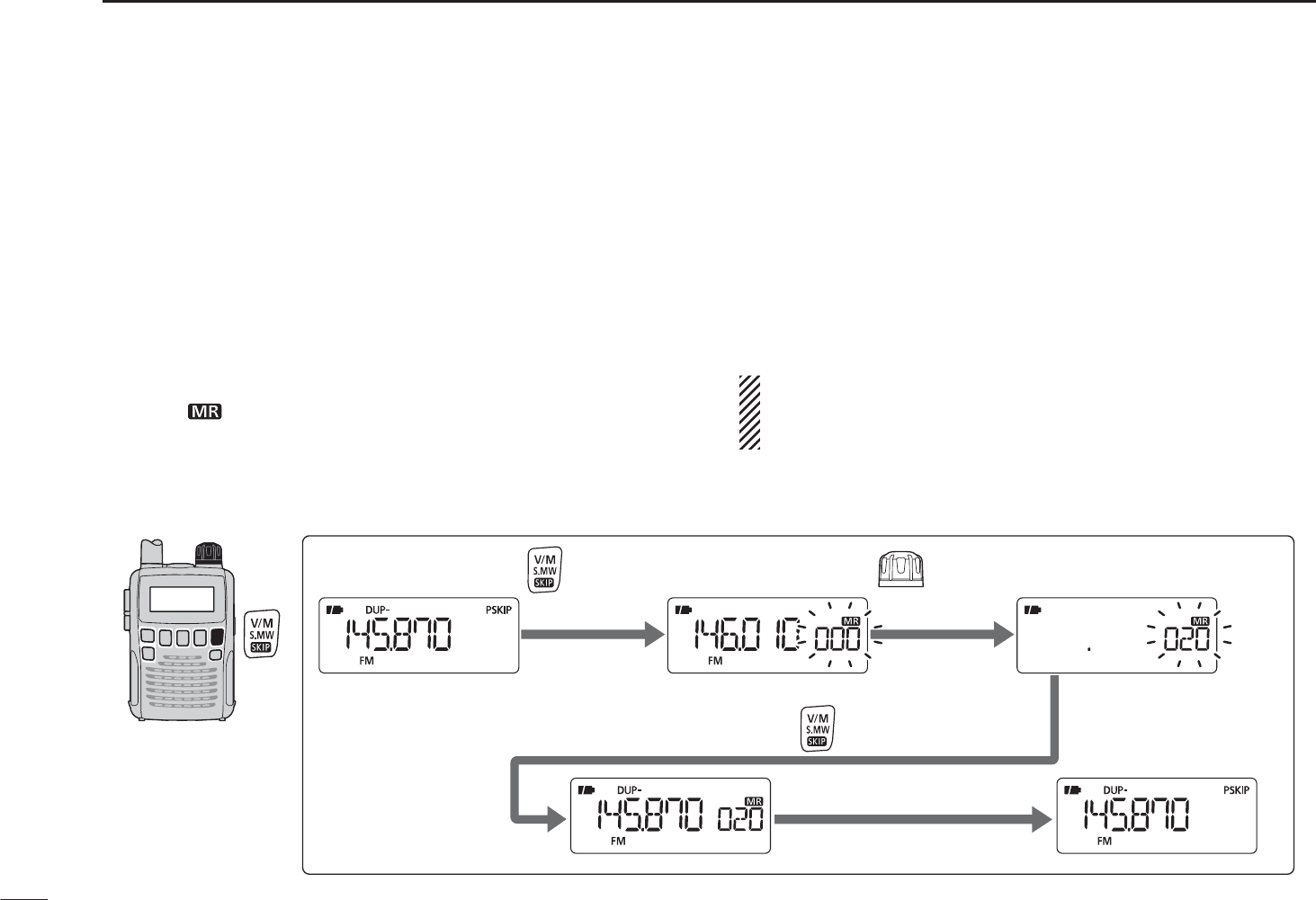
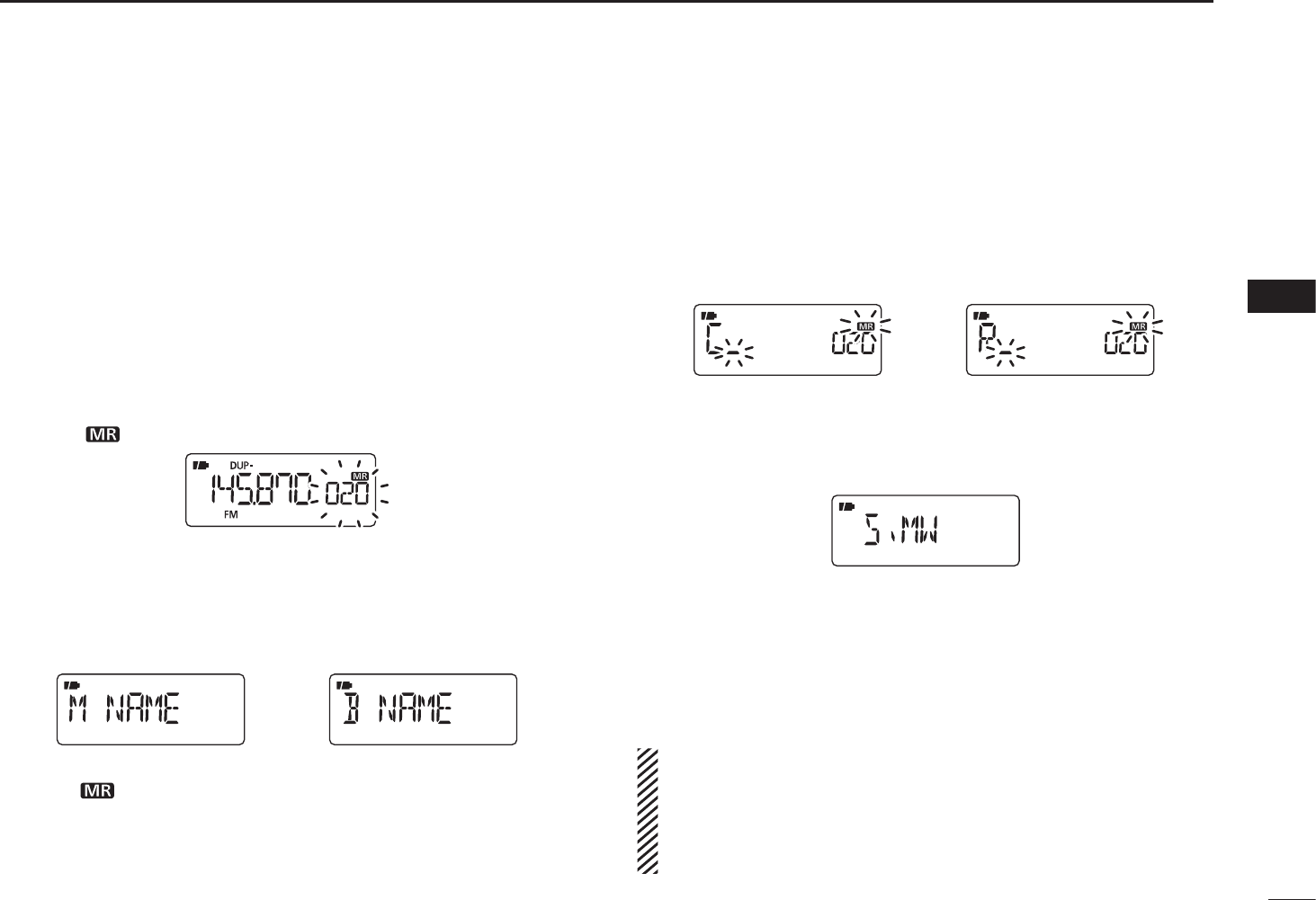
N
Memory channel programming
qPush [V/M] to select the VFO mode.
wSet a desired frequency:
± Select a desired band with [BAND].
± Set a desired frequency with [DIAL].
±Set other data (e.g. frequency offset, duplex direction, tone
squelch, etc.), if desired.
e Hold down [S.MW](V/M) for 1 second to enter the select
memory write mode.
• 1 short and 1 long beep sound.
• The “ ” icon and memory channel number blink.
rRotate [DIAL] to select a desired channel.
• Scan edge channels, 00A/B to 24A/B can also be selected.
• While holding down [FUNC], rotate [DIAL] to select memory
channels in 10 channel steps.
tHold down [S.MW](V/M) for 1 second.
• 3 beeps sound
• The memory channel number automatically increases when
holding down [S.MW](V/M) after programming.
NOTE: Push [V/M] to cancel programming and exit the
select memory write mode, before memory programming
is finished.
RotateHold down for 1 sec. to select channel 20.
Hold down for 1 sec. to program.
The VFO mode Enter the select memory write mode.
Return to the VFO mode.
[EXAMPLE]: Programming 145.870 MHz into memory channel 20 (a blank channel).
20
5
MEMORY CHANNELS
1
2
3
4
5
6
7
8
9
10
11
12
13
14
15
16
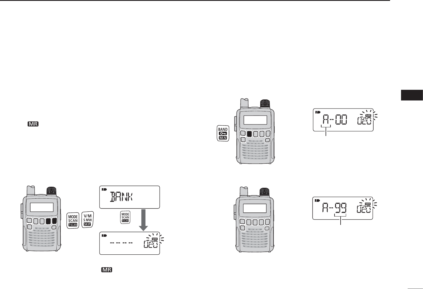
N Memory bank setting
The IC-R6 has a total of 22 banks (A to R, T, U, W and Y).
Regular memory channels 000 to 1299, and scan edge
memory channels 00A to 24B, can be assigned to any
desired bank, for easy memory management.
q Hold down [S.MW](V/M) for 1 second to enter the select
memory write mode.
• 1 short and 1 long beep sound.
• The “ ” icon and memory channel number blink.
wRotate [DIAL] to select a desired memory channel.
e While holding down [MODE], rotate [DIAL] to select the
“BANK” item.
• The bank group and channel number are displayed if the select-
ed memory channel has already been assigned to a bank.
• The “BANK” item can also be selected by pushing [MODE]
repeatedly.
[DIAL]
After
released.
• After releasing [MODE], “-- -- -- --” is displayed instead of the
frequency display, and only the “ ” icon blinks.
r While holding down [BAND], rotate [DIAL] to select a
desired bank group.
• Bank groups A to R, T, U, W and Y are available.
• The bank groups can also be selected by repeatedly pushing
[BAND].
[DIAL]
Bank group
tRotate [DIAL] to select a desired bank channel number.
• Only vacant bank channel numbers are displayed.
[DIAL]
Bank channel
y Hold down [S.MW](V/M) for 1 second to assign the chan-
nel to the bank.
• Return to the previous screen before entering the select memo-
ry write mode.
21
5MEMORY CHANNELS
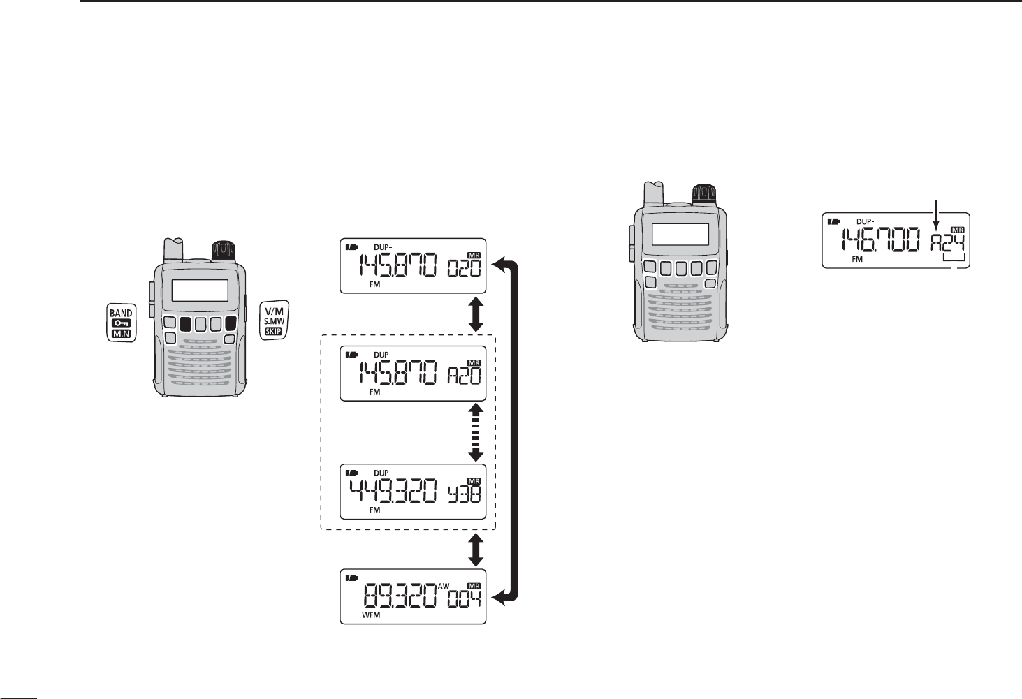
N Memory bank selection
qPush [V/M] to select the memory mode.
w While holding down [BAND], rotate [DIAL] to select a
desired bank.
• The bank can also be selected by pushing [BAND] repeatedly.
• Only banks with entries are displayed.
[DIAL]
Auto write channels
Regular memory
channels
Only banks with
entries are displayed
e Rotate [DIAL] to select the bank channel.
• Only programmed channels are displayed.
[DIAL] Bank initial
Bank chanel number
r To return to a regular memory channel, rotate [DIAL]
while holding down [BAND], or repeatedly push [BAND].
22
5
MEMORY CHANNELS
5
Each memory channel can be programmed with an alpha-
numeric channel name for easy recognition, and can be dis-
played independently by channel. Names can be a maximum
of 6 characters.
qPush [V/M] to select the memory mode.
wRotate [DIAL] to select a desired memory channel.
e Hold down [S.MW](V/M) for 1 second to enter the select
memory write mode.
• 1 short and 1 long beep sound.
• The “ ” icon and memory channel number blink.
r While holding down [MODE], rotate [DIAL] to select the
“M NAME” or “B NAME” item when programming the
memory name or the bank name, respectively.
• The item can also be selected by pushing [MODE] repeatedly.
Bank name selectionMemory name selection
• After releasing [MODE], a line blinks under the first digit, and
the “ ” icon blinks.
t While holding down [FUNC], rotate [DIAL] to select a
desired character.
• The selected character blinks.
yRotate [DIAL] to move the cursor to the left or to the right.
Bank nameMemory name
u Repeat steps t and y until a desired 6-character chan-
nel name is displayed.
i Push [MODE] repeatedly, or rotate [DIAL] while holding
down [MODE] to select the “S.MW” item.
o Hold down [S.MW](V/M) for 1 second to program the
name and exit the programming mode.
• 3 beeps sound.
• Available characters
A to Z, 0 to 9, ( , ) , , +, –, , /, |, = and space.
NOTE: Only one bank name can be programmed into
each bank. Therefore, the previously programmed bank
name will be displayed when bank name is selected. Also,
the programmed bank name is automatically assigned to
another bank channel.
N Programming memory/bank name
23
5MEMORY CHANNELS
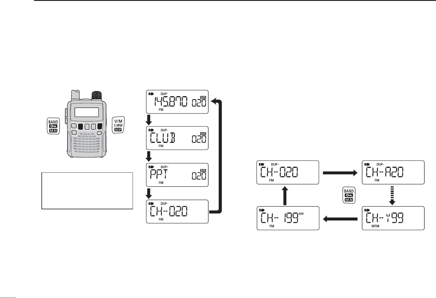
N Selecting display type
During memory mode operation, either the programmed
bank name, memory name or the channel number can be
displayed instead of the frequency display.
[DIAL]
Frequency display
Bank name display
Memory name display
Channel number display
qPush [V/M] to select the memory mode.
• If desired, push [BAND] repeatedly to select a desired bank
group.
w While holding down [FUNC], push [BAND] repeatedly to
select the display type from frequency, bank name, mem-
ory name or the channel number.
D Selecting bank channel display
During bank channel operation, the bank channel number
can also be displayed, instead of the memory channel
number.
qSelect the channel number display as described to the
left.
w While holding down [BAND], rotate [DIAL] to select a
desired bank.
• The bank can also be selected by pushing [BAND] repeatedly.
Push
Memory channel
number display
Bank channel
number display
Bank channel
number display
Auto write channel
number display
When the selected memory
channel has no programmed the
bank name or memory name,
the frequency is displayed.
24
5
MEMORY CHANNELS
5
N
Copying memory contents
This function transfers a memory channel’s contents to the
VFO (or another memory channel). This is useful when search-
ing for signals around a memory channel frequency and for
recalling the frequency offset, subaudible tone frequency etc.
DMemoryDVFO
qSelect the memory channel to be copied.
±Push [V/M] to select the memory mode, then rotate
[DIAL] to select a desired channel.
• If desired, push [BAND] repeatedly to select a desired bank
group, then rotate [DIAL] to select a desired bank channel.
w Hold down [S.MW](V/M) for 1 second to enter the select
memory write mode.
• 1 short and 1 long beep sound.
• The “ ” icon and memory channel number blink.
eRotate [DIAL] to select “VF.”
r Hold down [S.MW](V/M) for 1 second to write the selected
channel contents into the VFO.
• Automatically returns to the VFO mode.
Holding down [S.MW](V/M) for 2 seconds in step w will
also copy the memory contents to the VFO. In that case,
steps e and r are not necessary.
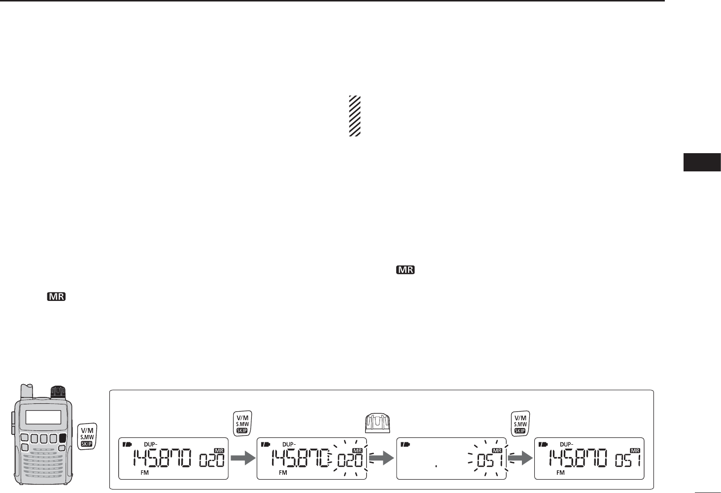
DMemoryDmemory
qSelect the memory channel to be copied.
±
Push
[V/M]
to select the memory mode, then rotate
[DIAL] to select a desired channel.
w Hold down [S.MW](V/M) for 1 second to enter the select
memory write mode.
• 1 short and 1 long beep sound.
• The “ ” icon and memory channel number blink.
• Do not hold down [S.MW](V/M) for more than 2 seconds.
Otherwise the memory contents will be copied to the VFO.
eRotate [DIAL] to select the target memory channel.
r Hold down [S.MW](V/M) for 1 second again to copy.
Rotate .
Hold down for 1 sec. Hold down for 1 sec. to program.
Select the memory channel
[EXAMPLE]: Copying channel 20 to 51.
25
5MEMORY CHANNELS
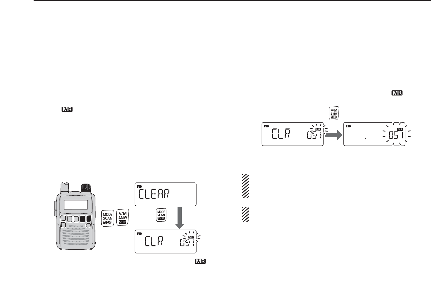
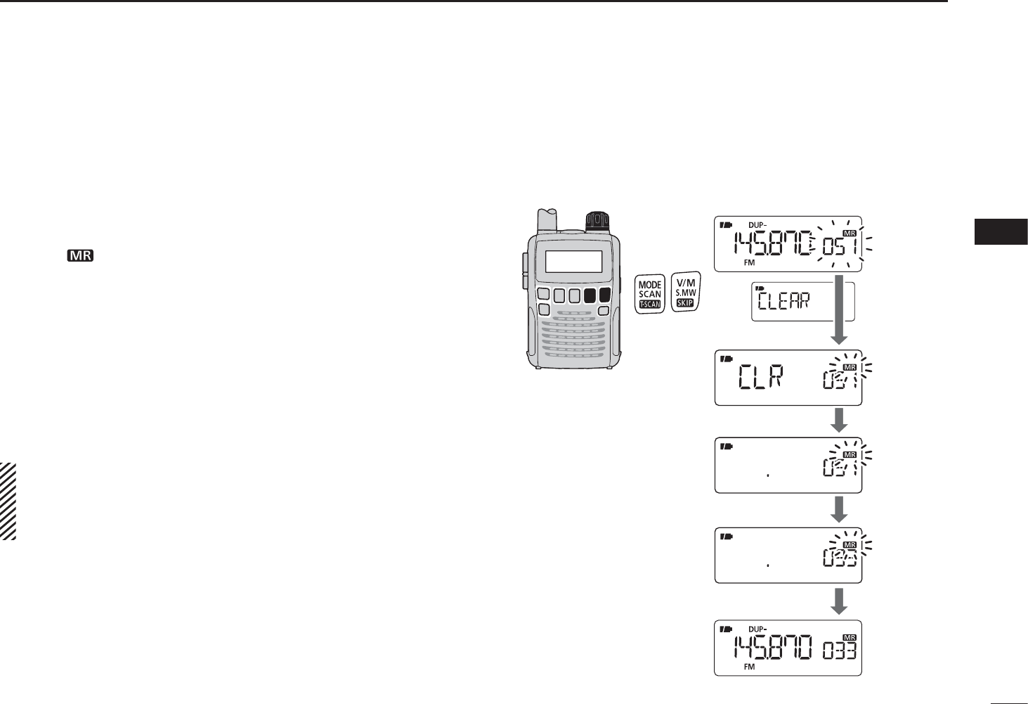
N Memory clearing
Contents of programmed memories can be cleared (erased),
if desired.
q Hold down [S.MW](V/M) for 1 second to enter the select
memory write mode.
• 1 short and 1 long beep sounds.
• The “ ” icon and memory channel number blink.
• Do not hold down [S.MW](V/M) for more than 2 seconds.
Otherwise the memory contents will be copied to the VFO.
w Rotate [DIAL] to select a desired memory channel to be
cleared.
e While holding down [MODE], rotate [DIAL] to select the
“CLEAR” item.
• The “CLEAR” item can also be selected by pushing [MODE]
repeatedly.
[DIAL]
After
released.
• After releasing [MODE], “CLR” is displayed and the “ ” icon
blinks.
r Hold down [S.MW](V/M) for 1 second to clear the con-
tents.
• 3 beeps sound.
• The cleared channel changes to a blank channel.
• Return to the select memory write mode.— The “ ” icon and
memory channel number blink.
Push and hold for 1 sec.
t Push [V/M] to return to the screen displayed before you
the select memory write mode in step q.
After step w, while holding down [FUNC], push and hold
[S.MW] (V/M) for 1 second can also be clear the con-
tents. In that case, steps e and r are not necessary.
BE CAREFUL!— The contents of cleared memories
CANNOT be recalled, even in the bank channel mode.
26
5
MEMORY CHANNELS
5
N
Transferring memory contents
The contents of programmed memory channels can be
transferred to another memory channels.
q Hold down [S.MW](V/M) for 1 second to enter the select
memory write mode.
• 1 short and 1 long beep sounds.
• The “ ” icon and memory channel number blink.
• Do not hold down [S.MW](V/M) for more than 2 seconds.
Otherwise the memory contents will be copied to the VFO.
w Rotate [DIAL] to select a desired memory channel to be
transferred.
e While holding down [MODE], rotate [DIAL] to select the
“CLEAR” item, then release [MODE].
• Pushing [MODE] repeatedly also selects the “CLEAR” item.
rHold down [S.MW](V/M) for 1 second.
• The displayed contents are cleared.
CONVENIENT!:
Instead of doing steps e and r, while holding down
[FUNC], push and hold [S.MW](V/M) for 1 second also
clears the contents.
t
Rotate [DIAL] to select a desired target memory channel.
y Hold down [S.MW](V/M) for 1 second to transfer the con-
tents.
[DIAL]
• Example
Transferring the contents of memory
channel 51 to channel 33.
Steps q and w
Step e
Step r
Step t
Step y
27
5MEMORY CHANNELS
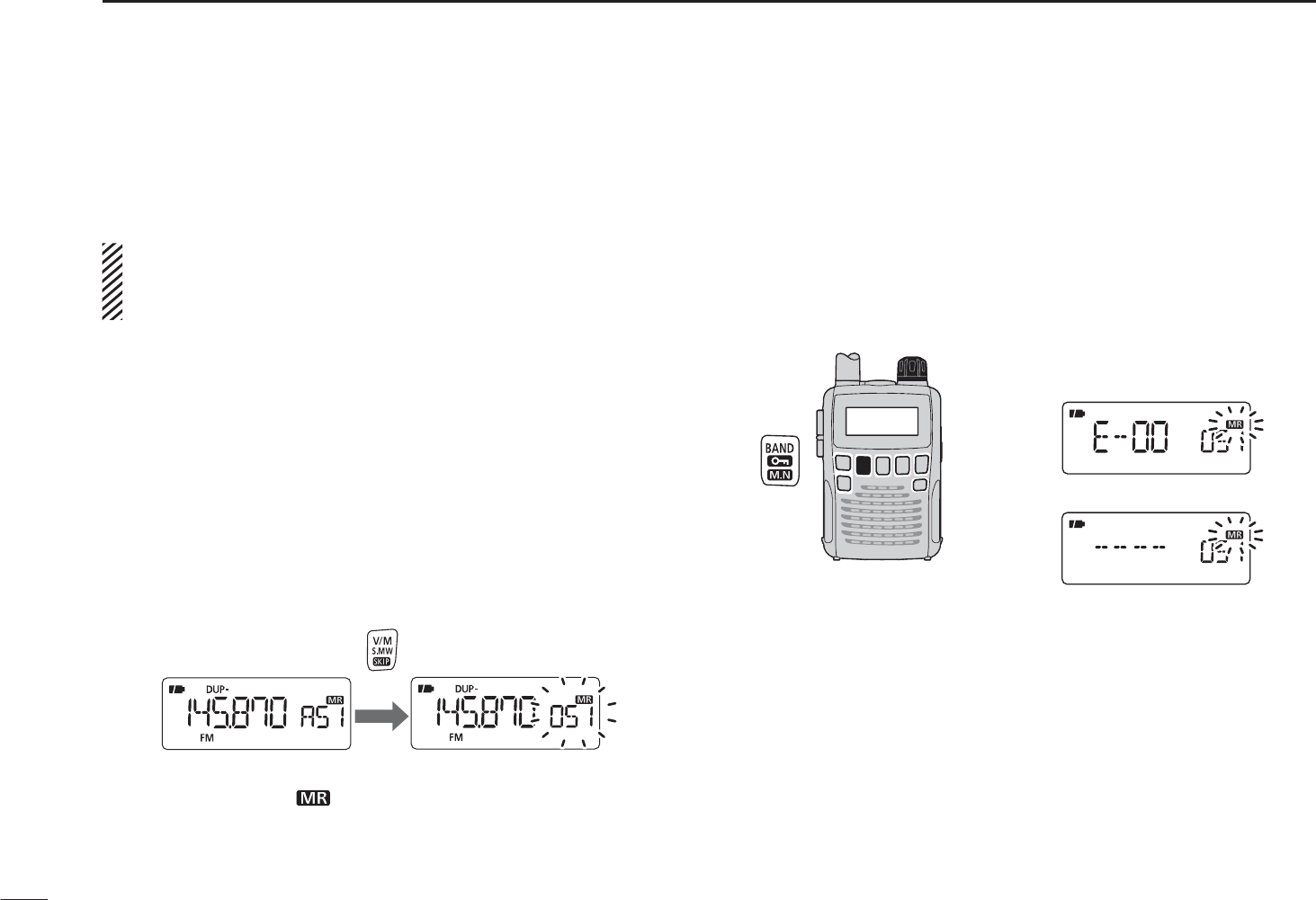
The contents of programmed memory channels can be
erased or transferred to another memory.
INFORMATION: Even if the memory bank contents are
erased, the memory channel contents still remain pro-
grammed.
q Select a desired bank contents to be transferred or erased
from the bank.
± Push [V/M] to select the memory mode.
±While holding down [BAND], rotate [DIAL] to select a
desired memory bank group.
± Rotate [DIAL] to select the bank channel.
w Hold down [S.MW](V/M) for 1 second to enter the select
memory write mode.
• 1 short and 1 long beep sounds.
• Do not hold down [S.MW](V/M) for more than 2 seconds.
Otherwise the bank contents will be copied to the VFO.
Push and hold for 1 sec.
• The original memory channel number is automatically dis-
played, then the “ ” icon and the memory channel number
blink.
e While holding down [MODE], rotate [DIAL] to select the
“BANK” item.
• Pushing [MODE] repeatedly also selects the “BANK” item.
r While holding down [BAND], rotate [DIAL] to select a
desired bank group to transfer.
• Select the “-- -- -- --” display when erasing the contents from the
bank.
[DIAL] To transfer the bank contents
in bank E.
To erase
tRotate [DIAL] to select a desired bank channel.
y While holding down [MODE], rotate [DIAL] to select the
“S.MW” item.
• Pushing [MODE] repeatedly also selects the “S.MW” item.
u Hold down [S.MW](V/M) for 1 second to erase or transfer
the bank contents.
N Erasing/transferring bank contents
28
6
SCAN OPERATION
1
2
3
4
5
6
7
8
9
10
11
12
13
14
15
16
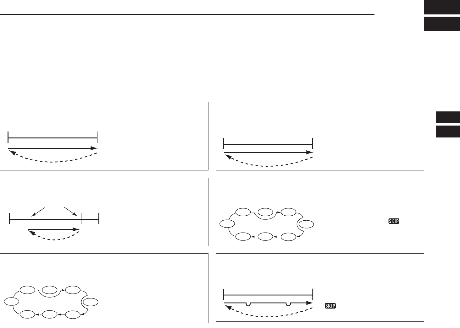
N Scan types
Scanning automatically searches for signals and makes it
easier to locate new stations for listening purposes.
There are 7 scan types and 4 resume options to suit your
operating needs.
FULL SCAN (p. 26)
100
kHz
1309.995
MHz
Scan
Jump
Repeatedly scans all frequen-
cies over the entire band.
Some frequency ranges are
not scanned, depending on
the frequency coverage of the
receiver version.
SELECTED BAND SCAN
(p. 26)
Band
edge
Band
edge
Scan
Jump
Repeatedly scans all fre-
quencies over the entire
selected band.
ALL/SELECTED BANK
SCAN (p. 28)
SKIP
SKIP
A99 A03
A00 A01 A02
A04
A98
A05
Repeatedly scans all bank
channels or selected bank
channels. The skip scan is
also selectable.
FREQUENCY/MEMORY
SKIP FUNCTION (p. 30)
Band
edge
Band
edge
Scan
SKIP SKIP
Jump
Skips unwanted frequencies
or channels that inconven-
iently stop scanning. This
function can be turned ON
or OFF by pushing [FUNC] +
[ ](V/M) in either the VFO
or the memory mode.
PROGRAMMED SCAN
(p. 26)
Band
edge xxA xxB
Band
edge
Scan edges
Scan
Jump
Repeatedly scans between
two user-programmed fre-
quencies. Used to check for
frequencies within a specified
range, such as repeater out-
put frequencies, etc.
MEMORY (SKIP) SCAN
(p. 28)
SKIP
SKIP
M0 M4
M1 M2 M3
M5
M 199
M6
Repeatedly scans memory
channels, except those set as
skip channels. Skip channels
can be turned ON or OFF by
pushing [FUNC] + [ ](V/M)
in the memory mode.
29
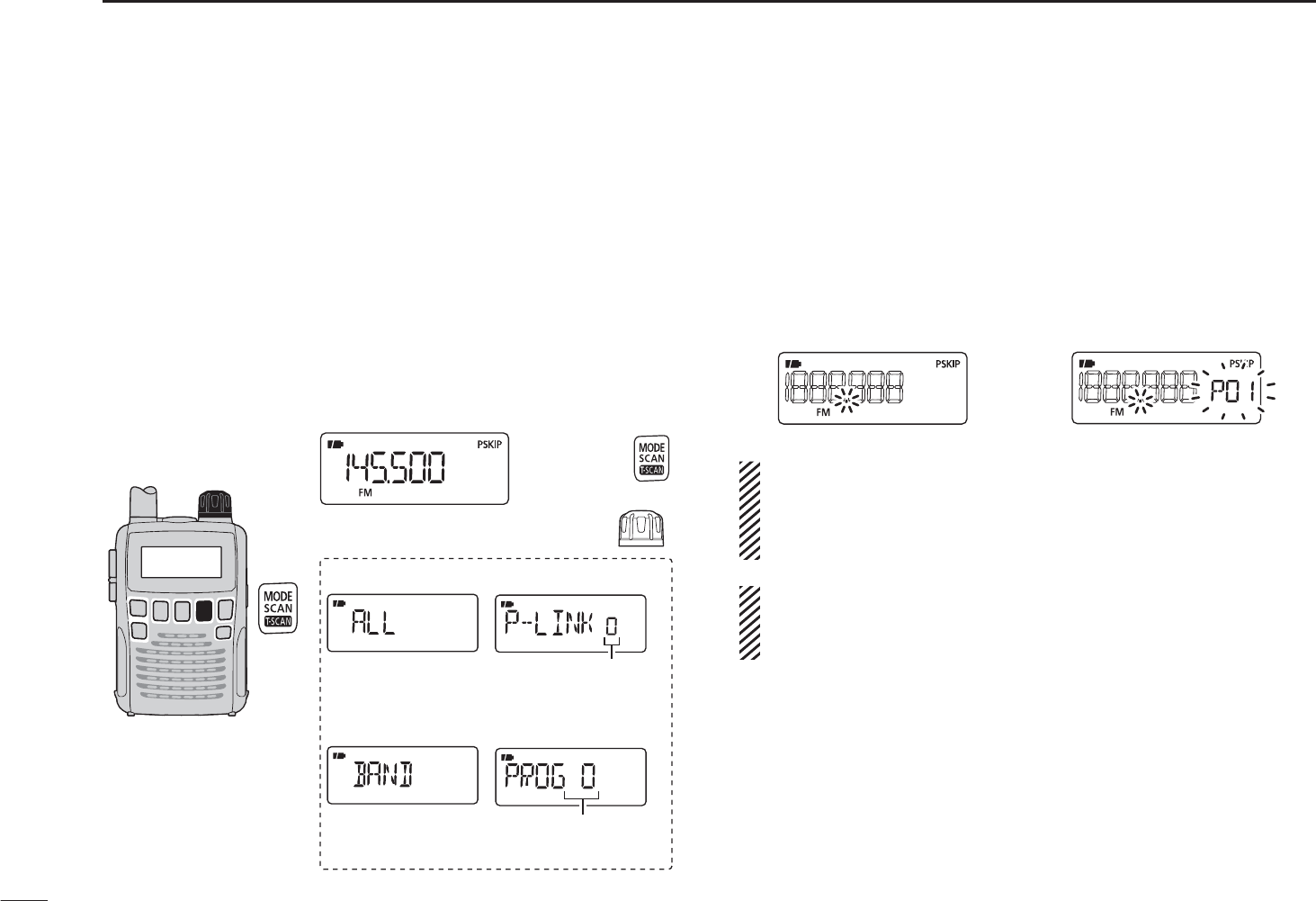
6SCAN OPERATION
qPush [V/M] to select the VFO mode.
• Push [BAND] to
select a desired frequency band.
wSet the squelch level.
e Hold down [SCAN](MODE) for 1 second to enter the scan
type selection mode.
rRotate [DIAL] to select a desired scanning type.
• Select “ALL” for full scan, “BAND” for band scan, “P-LINK x” for
programmed link scan (x= 0 to 9), “PROGxx” for programmed
scan (xx= 0 to 24; only programmed scan edge numbers are
displayed).
[DIAL]
Selectable between
“0” to “24” if programmed
Selectable between
“0” to “9” if programmed
• Full scan
• Band scan
• Program link scan
• Program scan
Rotate
Hold down
for 1 sec.
tTo start the scan, push [SCAN](MODE).
• The scan pauses when a signal is received.
• Rotate [DIAL] to change the scanning direction. This also
resumes scanning.
• Push [SCAN](MODE) again to stop the scan.
During full/band scan During programmed/
link program scan
NOTE: Instead of doing steps e to t, while holding
down [SCAN](MODE), rotate [DIAL] to select a desired
scan type. In this case, the scan starts after releasing
[SCAN](MODE).
About the scanning steps: The VFO mode, the selected
tuning step in each frequency band is used during the
scan.
N Full/band/programmed link/programmed scan
30
6
SCAN OPERATION
1
2
3
4
5
6
7
8
9
10
11
12
13
14
15
16
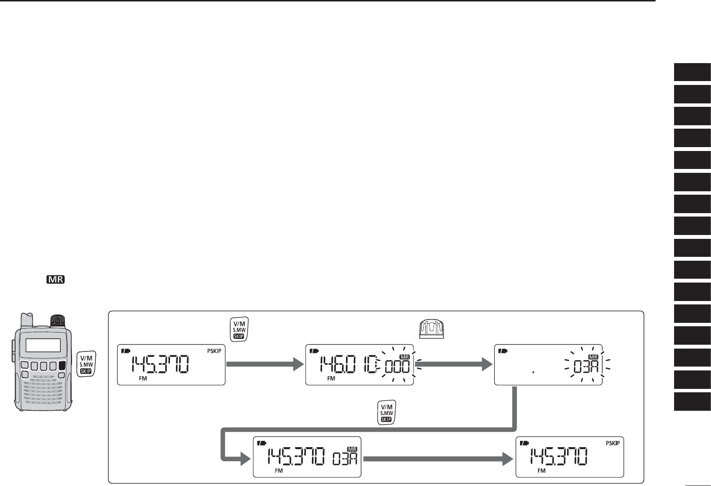
N Scan edges programming
Scan edges can be programmed in the same manner as
memory channels. Scan edges are programmed into scan
edge memory channels, 00A/00B to 24A/24B.
qPush [V/M] to select the VFO mode.
wSet a desired frequency:
± Push [BAND] to select a desired band.
± Rotate [DIAL] to set a desired frequency.
±Set other data (e.g. offset frequency, duplex direction, tone
squelch, etc.), if desired.
e Hold down [S.MW](V/M) for 1 second to enter the select
memory write mode.
• 1 short and 1 long beep sounds.
• The “ ” icon and memory channel number blink.
r Rotate [DIAL] to select a desired programmed scan edge
channel from 00A to 24A.
tHold down [S.MW](V/M) for 1 second.
• 3 beeps sound
• The matched “B” channel is automatically selected when hold-
ing down [S.MW](V/M) after programming.
y To program a frequency for the other pair of scan edges,
00B or 24B, repeat steps w and r.
• If the same frequency is programmed into a pair of scan edges,
programmed scan will not function.
RotateHold down for 1 sec. to select channel 03A.
Hold down for 1 sec. to program.
The VFO mode Enter the select memory write mode.
Return to the VFO mode.
[EXAMPLE]: Programming 145.370 MHz into scan edge channel 03A (a blank channel).
31
6SCAN OPERATION
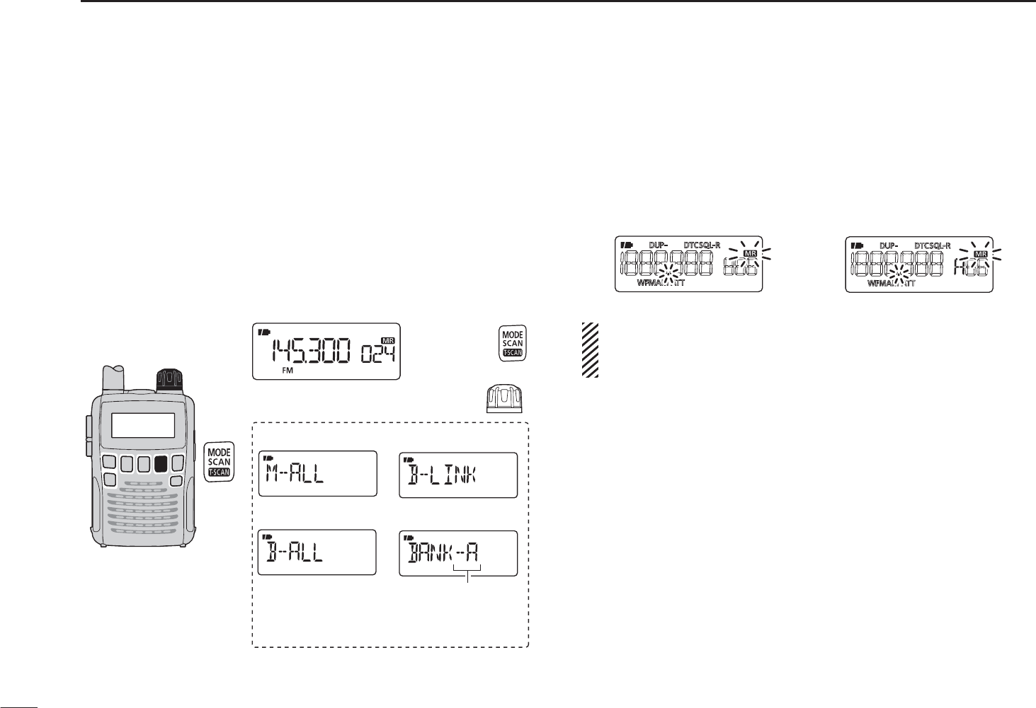
N Memory/all bank/bank link/bank scan
qPush [V/M] to select the memory mode.
wSet the squelch level.
e Hold down [SCAN](MODE) for 1 second to enter the scan
type selection mode.
rRotate [DIAL] to select a desired scanning type.
• Select “M-ALL” for all memory scan, “B-ALL” for all bank scan,
“B-LINK” for bank link scan or “BANK-x” for bank scan (x= A to
R, T, U, W, Y; only programmed bank groups are displayed).
[DIAL]
• All memory scan
• All bank scan
• Bank link scan
• Bank scan
Selectable between
“A” to “R,” “T,” “U,” “W” or “Y,”
if programmed
Rotate
Hold down
for 1 sec.
tTo start the scan, push [SCAN](MODE).
• The scan pauses when a signal is received.
• Rotate [DIAL] to change the scanning direction. This also
resumes scanning.
• Push [SCAN](MODE) again to stop the scan.
During memory/
all bank/bank link scan
During bank scan
IMPORTANT!: To perform a memory or bank scan, two or
more memory/bank channels MUST be programmed,
otherwise the scan will not start.
32
6
SCAN OPERATION
6
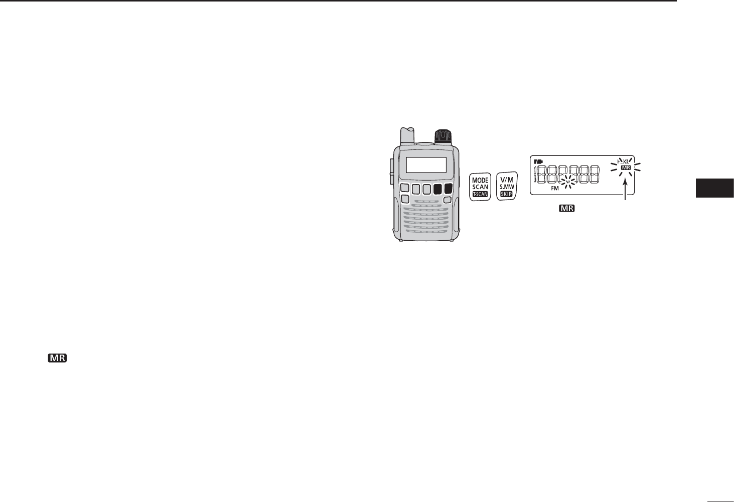
N Auto memory write scan
This scan is useful for searching a specified frequency
range, and automatically storing busy frequencies into
memory channels. The same frequency ranges used for a
program scan are used for an auto memory write scan.
qStart a VFO scan.
± Push [V/M] to select the VFO mode.
± Set the squelch level.
±Hold down [SCAN](MODE) for 1 second to enter the
scan type selection mode.
± Rotate [DIAL] to select a desired scanning type.
• Select “ALL” for full scan, “BAND” for band scan, “P-LINK
x” for programmed link scan (x= 0 to 9), “PROGxx” for pro-
grammed scan (xx= 0 to 24; only programmed scan edge
numbers are displayed).
± Push [SCAN](MODE) to start the scan.
w Push [V/M] to turn the auto memory write function ON or
OFF.
• The “ ” icon blinks.
• Push [SCAN](MODE) to stop the scan.
[DIAL] • During auto memory
write scan
The “ ” icon blinks
during auto memory
write scan.

33
6SCAN OPERATION
D During auto memory write scanning:
• When a signal is received, the scan pauses and the
frequency is stored into an auto memory write channel
group (AW000–AW199).
- 2 short beeps sound when stored.
• Scan resumes after frequency storing.
• When all channels are stored, the scan automatically
stops and 1 long beep sounds.
D Re-calling the stored frequencies:
q Push [V/M] to select the memory mode.
w Push [BAND] repeatedly, or while holding down [BAND],
rotate [DIAL],to select the auto memory write channel group.
• “AW” appears.
eRotate [DIAL] to select a desired channel.
“AW” appears when the
auto memory write channel
group is selected.
D Clearing the stored frequencies:
qSelect the auto memory write channel group.
w While holding down [FUNC], push and hold [S.MW](V/M)
for 1 second to clear the all channels contents.
• 1 short and 1 long beep sounds.
NOTE: The auto memory write channel contents CANNOT
be cleared by an independent channel. Thus it is good
idea to copy the contents into a regular memory channel.
34
6
SCAN OPERATION
6
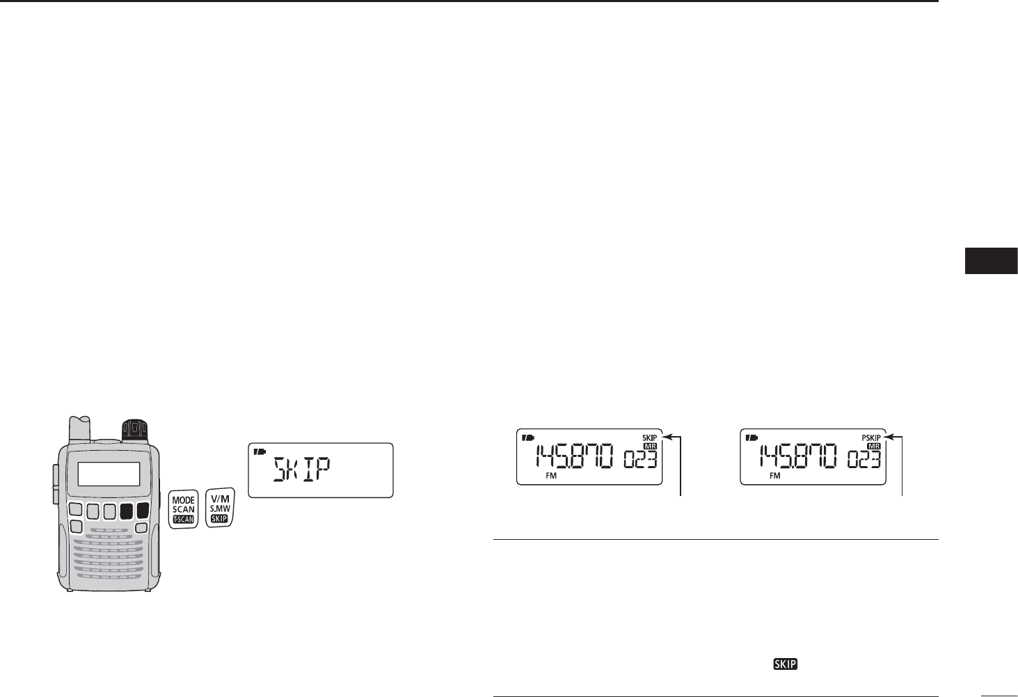
Memory channels can be set to be skipped for a memory
skip scan. In addition, memory channels can be set to be
skipped for both a memory skip scan and a frequency skip
scan. These are useful to speed up the scan time.
qSelect a memory channel:
± Push [V/M] to select the memory mode.
±Rotate [DIAL] to select a desired channel to be a skip
channel/frequency.
w Hold down [S.MW](V/M) for 1 second to enter the select
memory write mode.
ePush [MODE] repeatedly to select the “SKIP” item.
• While holding down [MODE], rotating [DIAL] can also select
the “SKIP” item.
[DIAL] • Skip setting
r While holding down [FUNC], rotate [DIAL] to select the
skip option from “SKIP,” “PSKIP” or “OFF,” for the selected
channel.
• SKIP : The channel is skipped during a memory or bank scan.
• PSKIP : The channel is skipped during a memory/bank scan.
The programmed frequency is skipped during a VFO
scan, such as a programmed scan.
• OFF : The channel or programmed frequency is scanned dur-
ing any scan.
t Push [MODE] repeatedly, or while holding down [MODE],
rotate [DIAL] to select the “S.MW” item.
y
Hold down [S.MW](V/M) for 1 second to store the skip status.
• The “SKIP” or “PSKIP” icon appears, according to the skip
selection in step r.
• Skip channel setting • Program skip setting
“SKIP” appears “PSKIP” appears
CONVENIENT!
The skip setting can also be set using the following steps, for
easy setting.
q Select a desired memory channel to be set as a skip
channel/frequency.
w
While holding down [FUNC], push
[ ](V/M)
to select the
skip status from “SKIP,” “PSKIP” and “OFF (no indication).”
N Skip channel/frequency setting
35
6SCAN OPERATION
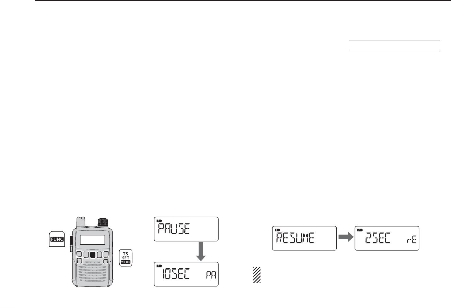
D Scan pause timer
The scan pauses when receiving signals according to the
scan pause time. It can be set from 2–20 seconds, or unlim-
ited.
qHold down [SET](TS) for 1 second to enter the Set mode.
wRotate [DIAL] to select the “EXPAND” item.
e While holding down [FUNC], rotate [DIAL] to turn the
Expand set mode selection ON.
rRotate [DIAL] to select the “PAUSE” item.
t While holding down [FUNC], rotate [DIAL] to set a
desired scan pausing time from 2–20 seconds (2 seconds
steps) or “HOLD.”
• “2SEC”–“20SEC”: Scan pauses 2–20 seconds while receiving
a signal.
• “HOLD” : Scan pauses on a received a signal until it
disappears.
yPush [SET](TS) to exit the Set mode.
[DIAL]
After 1 sec.
D Scan resume timer
The scan resumes after a signal disappears according to the
resume time. It can be set from 0–5 seconds, or unlimited.
qHold down [SET](TS) for 1 second to enter the Set mode.
wRotate [DIAL] to select the “EXPAND” item.
e While holding down [FUNC], rotate [DIAL] to turn the
Expand set mode selection ON.
rRotate [DIAL] to select the “RESUME” item.
t While holding down [FUNC], rotate [DIAL] to set a
desired scan pausing time from 0–5 seconds (1 second
steps) or “HOLD.”
• “0SEC” : Scan resumes immediately after the signal
disappears.
• “1SEC”–“5SEC” : Scan resumes 1–5 seconds after the signal
disappears.
• “HOLD” : Scan resumes by rotating [DIAL] only.
yPush [SET](TS) to exit the Set mode.
After 1 sec.
The scan resume timer must be set shorter than the scan
pause timer, otherwise this timer will not be activated.
N Scan resume setting USING EXPAND SET MODE
36
7
PRIORITY WATCH
6
7
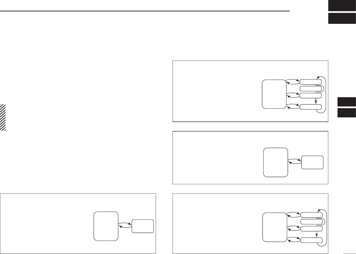
N Priority watch types
Priority watch checks for signals on a frequency every 5 sec-
onds, while operating on a VFO frequency or scanning. The
receiver has four priority watch types to suit your needs.
The watch resumes according to the selected scan resume
setting. See the left page for details.
NOTE:
If the pocket beep function is activated, the receiver auto-
matically selects the tone squelch or DTCS squelch func-
tion, when priority watch starts.
D About the priority beep function
When receiving a signal on the priority frequency, you can
be alerted with beeps and a blinking “S.” This function is
activated when setting the priority watch function ON.
MEMORY CHANNEL WATCH
While operating on a VFO fre-
quency, priority watch checks for
a signal on the selected memory
channel every 5 seconds.
• A memory channel with skip infor-
mation can be watched.
MEMORY SCAN WATCH
While operating on a VFO fre-
quency, priority watch sequen-
tially checks for signals on
each memory channel.
• The memory skip function and/or
memory bank scan is useful to
speed up the scan.
5 seconds
VFO
frequency
Memory
channel
5 seconds
VFO
frequency
SKIP
Mch 000
Mch 001
Mch 001
Mch 999
VFO SCAN WATCH
While scanning in the VFO
mode, priority watch checks for
signals on the selected memo-
ry channel every 5 seconds.
5 seconds
VFO
scan
Memory
channel
VFO SCAN WATCH
While scanning in the VFO
mode, priority watch sequen-
talliy checks for signals on
each memory channel every 5
seconds.
5 seconds
VFO
scan
SKIP
Mch 000
Mch 001
Mch 001
Mch 999
37
7PRIORITY WATCH
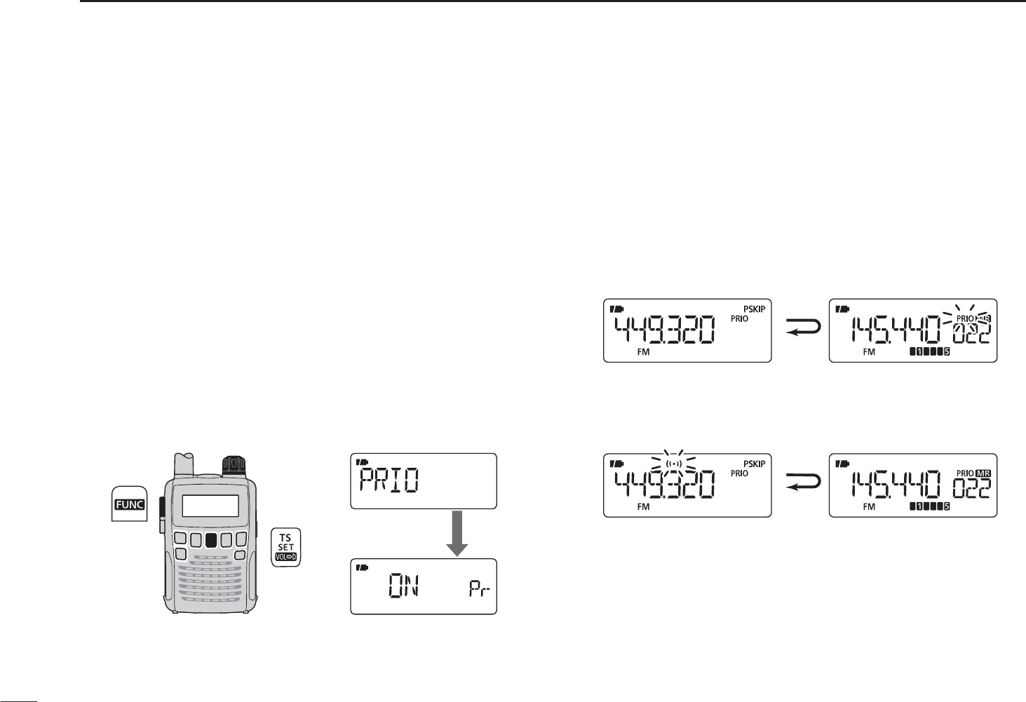
NPriority watch operation
D Memory channel/memory scan watch
qSelect the VFO mode; then, set an operating frequency.
wSelect the channel(s) to be watched.
For memory channel watch:
Select a desired memory channel.
For memory scan watch:
± Push [V/M] to select the memory mode.
±Hold down [SCAN](MODE) for 1 second to enter the
scan type selection mode.
±Rotate [DIAL] to select a desired scan type, then push
[SCAN](H/M/L) again to start the memory/bank scan.
eHold down [SET](TS) for 1 second to enter the Set mode.
rRotate [DIAL] to select the priority watch set item.
t While holding down [FUNC], rotate [DIAL] to select “ON.”
• Select “BELL” if the priority beep function is desired.
[DIAL]
After 1 sec.
Priority ON
yPush [TS] to exit the Set mode and start the watch.
• The “PRIO” icon appears.
• The receiver checks the memory/bank channel(s) every 5 sec-
onds.
• The watch resumes according to the selected scan resume set-
ting. (p. 31)
During priority watch
Monitors VFO frequency
for 5 seconds.
Pauses on a memory
channel when a signal is
received.
During priority watch with the priority beep
A beep tone sounds and “S” icon blinks when a signal
is received on a memory channel.
uPush [SET](TS) to cancel the watch.
38
7
PRIORITY WATCH
7
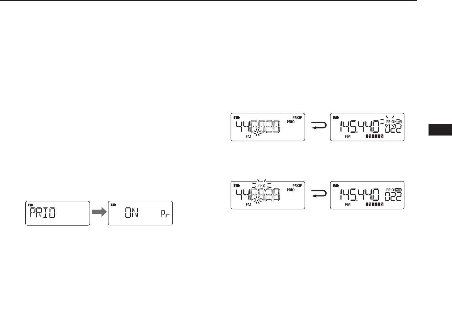
D VFO scan watch
qSelect the channel(s) to be watched.
For memory channel watch:
Select a desired memory channel.
For memory scan watch:
± Push [V/M] to select the memory mode.
±Hold down [SCAN](MODE) for 1 second to enter the
scan type selection mode.
±Rotate [DIAL] to select a desired scan type, then push
[SCAN](H/M/L) again to start the memory/bank scan.
wHold down [SET](TS) for 1 second to enter the Set mode.
eRotate [DIAL] to select the priority watch set item.
r While holding down [FUNC], rotate [DIAL] to select “ON.”
• Select “BELL” if the priority beep function is desired.
After 1 sec.
tPush [SET](TS) to exit the Set mode and start the watch.
• The “PRIO” icon appears.
y Hold down [SCAN](MODE) for 1 second to enter scan
type selection mode.
u Rotate [DIAL] to select a desired scan type from “ALL,”
“BAND,” “P-LINK x (x= 0 to 9)”or “PROGxx (xx= 0–24).”
iPush [SCAN](MODE) to start the VFO scan watch.
• The receiver checks the memory channel(s) every 5 seconds.
• The watch resumes according to the selected scan resume set-
ting. (p. 31)
During VFO watch
Searches VFO frequen-
cies for 5 seconds.
Pauses on a memory
channel when a signal is
received.
During VFO scan watch with the priority beep
A beep tone sounds and “S” icon blinks when a signal
is received on a memory channel.
oPush [TS] to cancel the watch and scan.
39
TONE SQUELCH AND POCKET BEEP
8
N Tone/DTCS squelch operation
The tone or DTCS squelch opens only when receiving a
signal with the same pre-programmed subaudible tone or
DTCS code, respectively. You can silently wait for the speci-
fied signal using the same tone.
qSet a desired frequency in the FM mode.
wHold down [SET](TS) for 1 second to enter the Set mode.
eRotate [DIAL] to select the “EXPAND” item.
r While holding down [FUNC], rotate [DIAL] to turn the
Expand set mode ON.
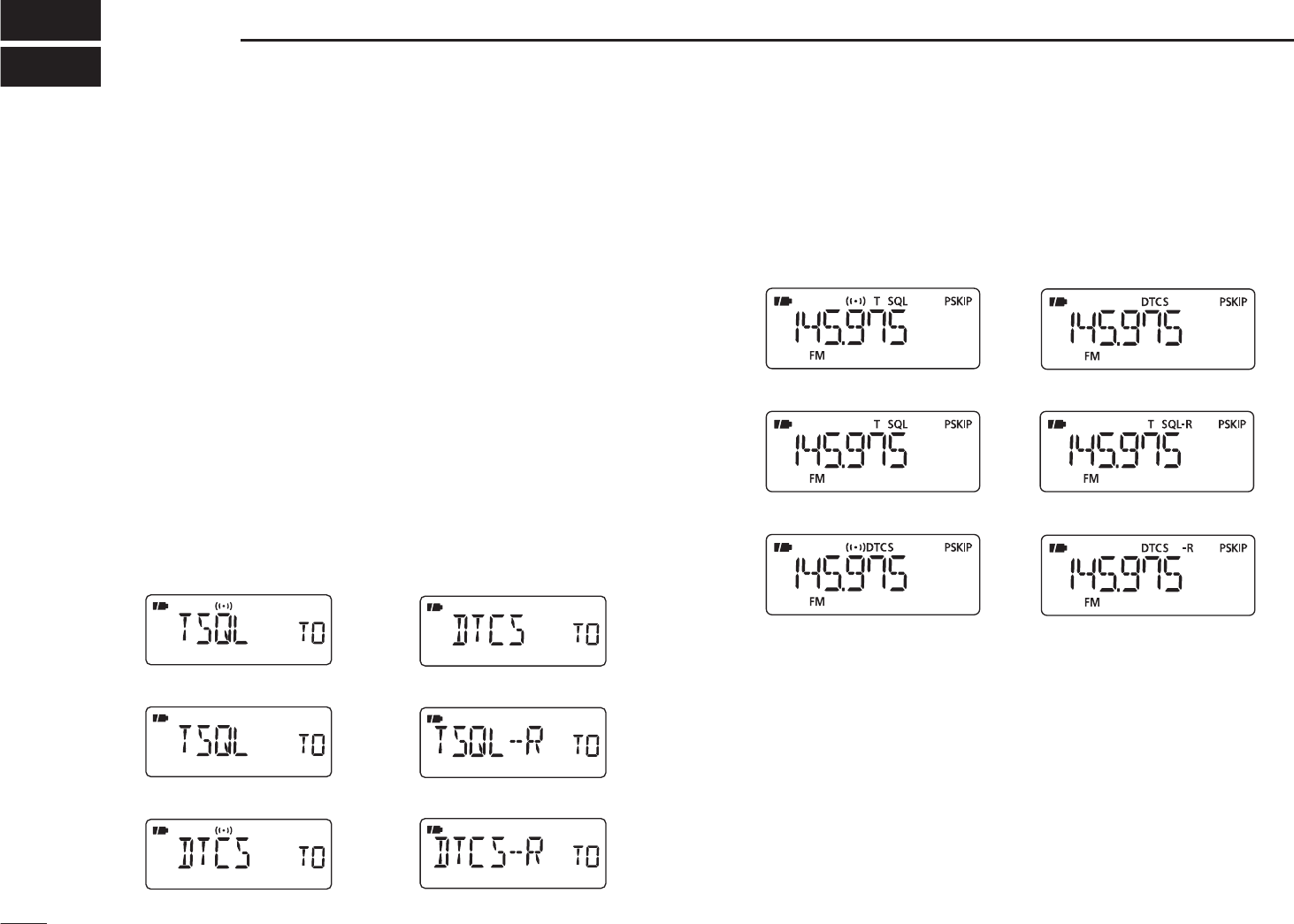
tRotate [DIAL] to select the “TSQL” item.
y While holding down [FUNC], rotate [DIAL] to select a
desired subaudible tone setting from “TSQLS,” “TSQL,”
“DTCS,” “DTCSS,” “TSQL (reverse),” “DTCS (reverse)”
or “OFF.”
Tone squelch
DTCS squelch
Tone squelch (reverse)
DTCS squelch (reverse)
Tone squelch with pocket beep
DTCS squelch with pocket beep
uPush [SET](TS) to exit the Set mode.
• One of “S T SQL,” T SQL,” “SDTCS,” “DTCS,” “T SQL-R”
or “DTCS -R” appears according to the tone selection in step y.
Tone squelch
DTCS squelch
DTCS squelch (reverse)
Tone squelch (reverse)
Tone squelch with pocket beep
DTCS squelch with pocket beep
i When a signal with the matched tone is received, the
squelch opens and the receiver emits audio.
When pocket beep function is activated, the receiver also
emits beep tones and blinks “S.”
• Beep tones sound and “S” blinks for 30 seconds.
oPush [FUNC] to stop the beeps and blinking manually.
• “S” disappears and the pocket beep function is deactivated.
!0 To cancel the tone squelch or DTCS, select “OFF” with the
“TSQL” item in the Expand set mode, as described in step
y.
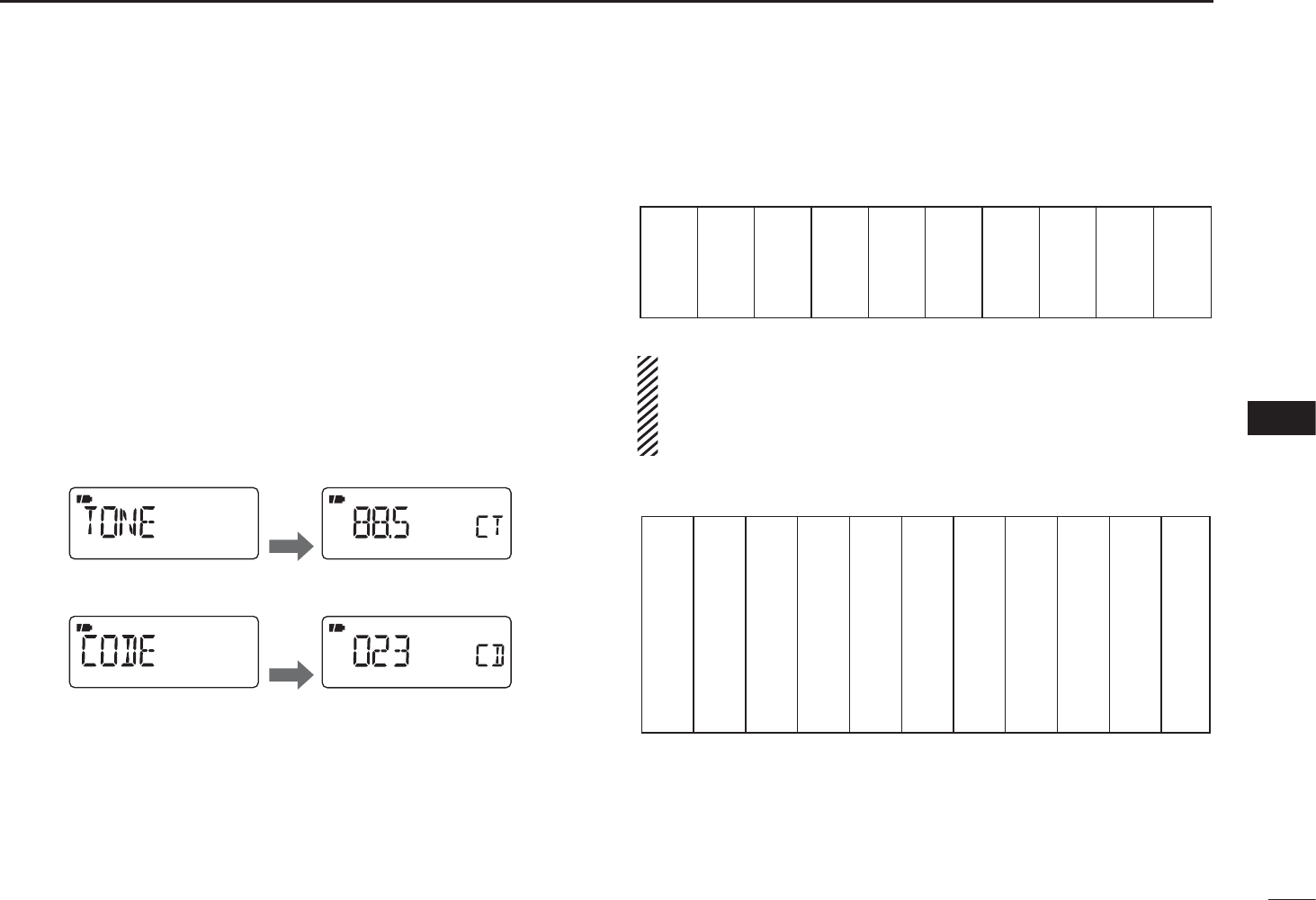
40
8
TONE SQUELCH AND POCKET BEEP
8
N Tone squelch frequency/DTCS code setting
88.5 Hz and 023 is set as the default for the tone squelch
frequency and the DTCS code, respectively. The frequency
and code can be selected as desired.
qHold down [SET](TS) for 1 second to enter the Set mode.
wRotate [DIAL] to select the “EXPAND” item.
e While holding down [FUNC], rotate [DIAL] to turn the
Expand set mode ON.
r Rotate [DIAL] to select the “TONE” item when selecting
the tone squelch frequency; select the “CODE” item when
selecting the DTCS code.
After
1 sec.
After
1 sec.
Tone squelch frequency selection
DTCS code selection
t While holding down [FUNC], rotate [DIAL] to select a
desired subaudible tone frequency or DTCS code.
• See the tables at right.
yPush [SET](TS) to exit the Set mode.
•Available tone frequency list
67.0
69.3
71.9
74.4
77.0
79.7
82.5
85.4
88.5
91.5
94.8
97.4
100.0
103.5
107.2
110.9
114.8
118.8
123.0
127.3
131.8
136.5
141.3
146.2
151.4
156.7
159.8
162.2
165.5
167.9
171.3
173.8
177.3
179.9
183.5
186.2
189.9
192.8
196.6
199.5
203.5
206.5
210.7
218.1
225.7
229.1
233.6
241.8
250.3
254.1
NOTE: The receiver has 50 tone frequencies and conse-
quently their spacing is narrow compared to units having
38 tones. Therefore, some tone frequencies may receive
interference from adjacent tone frequencies.
•Available DTCS code list
023
025
026
031
032
036
043
047
051
053
125
131
132
134
143
145
152
155
156
162
245
246
251
252
255
261
263
265
266
271
356
364
365
371
411
412
413
423
431
432
506
516
523
526
532
546
565
606
612
624
054
065
071
072
073
074
114
115
116
122
165
172
174
205
212
223
225
226
243
244
274
306
311
315
325
331
332
343
346
351
445
446
452
454
455
462
464
465
466
503
627
631
632
654
662
664
703
712
723
731
732
734
743
754
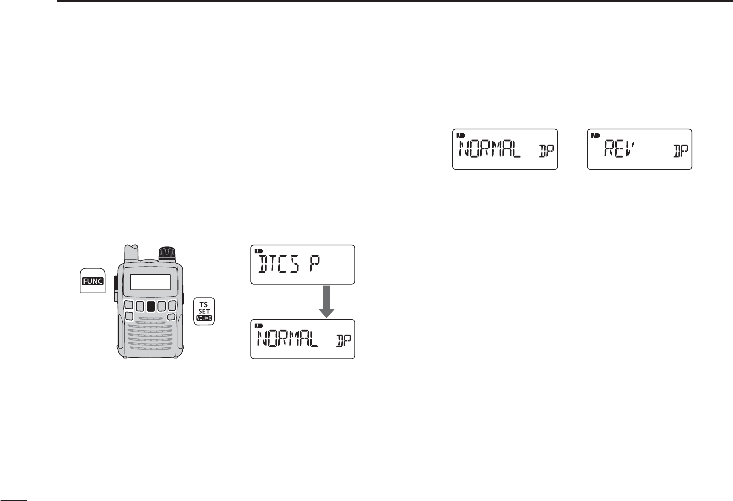
41
8TONE SQUELCH AND POCKET BEEP
N DTCS polarity setting
As well as the code setting, the polarity setting is also avail-
able for the DTCS operation. When a different polarity is
set, the DTCS never releases audio mute even a signal with
matched code number is received.
qHold down [SET](TS) for 1 second to enter the Set mode.
wRotate [DIAL] to select the “EXPAND” item.
e While holding down [FUNC], rotate [DIAL] to turn the
Expand set mode ON.
r Rotate [DIAL] to select the “DTCS P” item.
[DIAL]
After 1 sec.
t While holding down [FUNC], rotate [DIAL] to select the
polarity from normal (NORMAL) and reverse (REV).
Normal polarity Reverse polarity
yPush [SET](TS) to exit the Set mode.
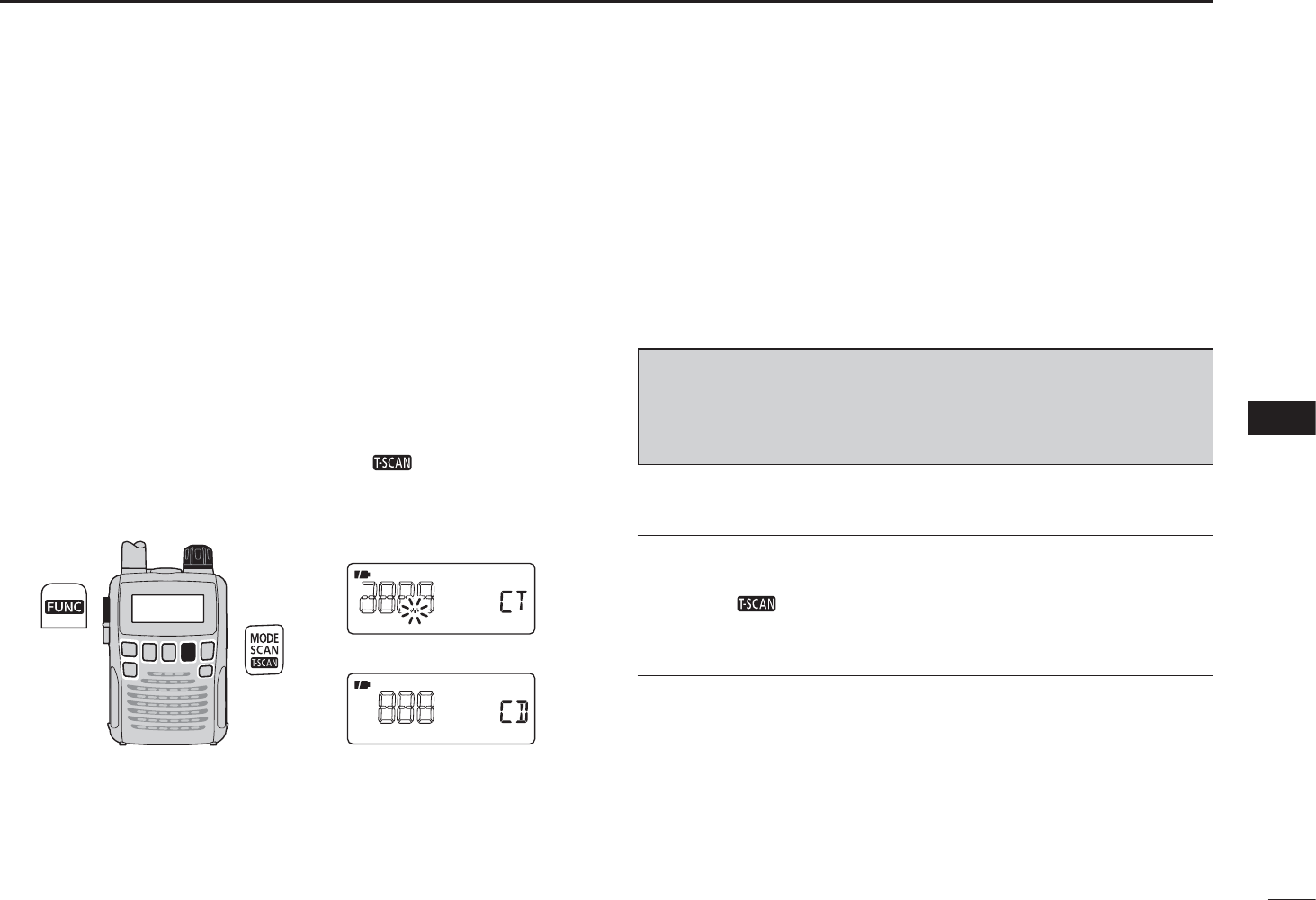
42
8
TONE SQUELCH AND POCKET BEEP
8
N Tone scan
By monitoring a signal that is being operated with pocket
beep, tone or DTCS squelch function, you can determine the
tone frequency or DTCS code necessary to open a squelch.
q Set the frequency to be checked for a tone frequency or
code.
w Turn a desired tone type, tone squelch or DTCS ON in the
Expand set mode.
• One of “TSQL” or “DTCS” appears.
• Even the pocket beep function is activated, the function is can-
celled when starts the tone scan.
e While holding down [FUNC], push [ ](MODE) to start
the tone scan.
• To change the scanning direction, rotate [DIAL].
[DIAL] Tone squelch scan
DTCS squelch scan
rWhen the CTCSS tone frequency or 3-digit DTCS code
is matched, the squelch opens and the tone frequency or
code is temporarily programmed into the selected condi-
tion, such as memory channel.
• The tone scan pauses when a CTCSS tone frequency or 3-digit
DTCS code is detected.
NOTE: The decoded tone frequency or code is pro-
grammed temporarily when a memory channel is selected.
However, this will be cleared when the other memory chan-
nel is selected.
For your convenient!
Even no tone type is selected, either tone squelch or DTCS,
pushing [ ](MODE) while holding down [FUNC] also
start tone scan. In this case, the tone scan searching for
tone squelch frequency only.
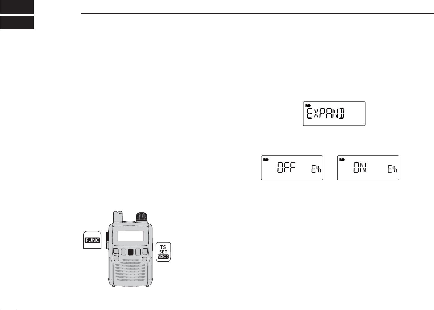
43
SET MODE
9
N General
Set mode is used for programming infrequently changed val-
ues or options of the functions.
In addition, the IC-R6 has the Expand set mode which is
used for programming even more infrequently changed val-
ues or options of the functions. When turning the Expand set
mode OFF, only half of the Set mode items are displayed for
simple operation.
D Set mode entering and operation
qHold down [SET](TS) for 1 second to enter the Set mode.
wRotate [DIAL] to select a desired item.
e While holding down [FUNC], rotate [DIAL] to select a
desired value or option.
r Push [SET](TS) to exit the Set mode, or repeat w and e
to set other items.
[DIAL]
D Expand set mode ON/OFF
qHold down [SET](TS) for 1 second to enter the Set mode.
wRotate [DIAL] to select the “EXPAND” item.
e While holding down [FUNC], rotate [DIAL] to turn the
Expand set mode ON or OFF.
Expand set mode OFF Expand set mode ON
rRotate [DIAL] to select a desired item.
t While holding down [FUNC], rotate [DIAL] to select a
desired value or option.
y Push [SET](TS) to exit the Set mode, or repeat r and t
to set other items.
44
9
SET MODE
9
N Set mode items
The following items are available in the Set mode and the
Expand set mode.
D General Set mode items
*Appears when accessing the Set mode in only the AM or FM
broadcast band mode.
D Expand set mode items
†Available in only the USA version.
Guide Item name Ref.
D SEL Dial select step ??
PRIO Priority watch ??
BEEP Key-touch beep ??
BEEPLV Beep output level ??
LIGHT Display backlighting ??
P SAVE Power save ??
ANT* Antenna selection ??
EXPAND Expand set mode ??
Guide Item name Ref.
LOCK Key lock effect ??
SPEED Dial speed acceleration ??
MONI Monitor switch action ??
AP OFF Auto power OFF ??
PAUSE Scan pause timer ??
RESUME Scan resume timer ??
STOP B Scan stop beep ??
OFFSET Frequency offset ??
DUP Duplex direction ??
TSQL Tone squelch ??
TONE Tone frequency ??
CODE DTCS code ??
DTCS P DTCS polarity ??
VSC Voice squelch control ??
B-LINK Band link ??
P-LINK Program link ??
CONT LCD contrast ??
WX ALT†Weather alert ??
AF FIL AF filter ??
CHARGE Charge ??
CIVADR CI-V address ??
CIVBAU CI-V baud rate ??
CIVTRN CI-V transceive ??
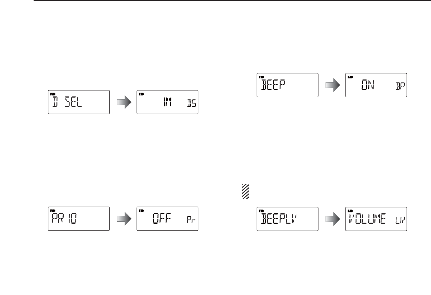
45
9SET MODE
D Dial select step
Select the tuning step between 100 kHz, 1 MHz (default)
and 10 MHz for a temporary faster frequency setting. When
setting a frequency with the increased tuning step, hold
down [FUNC], and then rotate [DIAL].
D Priority watch
Turn the priority watch or priority beep (priority watch with
beep sounds) ON. (default: OFF)
• OFF : Turns the function OFF.
• ON : Starts priority watch after exiting the Set mode.
• BELL : When a signal is received on the priority fre-
quency, beeps sound and the ((*)) icon blinks.
D Key-touch beep
The key-touch beep can be turned OFF for silent operation.
(default: ON)
D Beep output level
Adjust the key-touch beep tone level to one of 32 set levels,
or set it to follow the volume control level.
• VOLUME : The beep tone level is linked to the vol-
ume set level. (default)
• _ _ _ _ _ _ – ooo ooo
: The beep tone level is independently
adjustable at one of 32 levels.
The key-touch beep (previous item) must be set to ON to
have a beep tone.
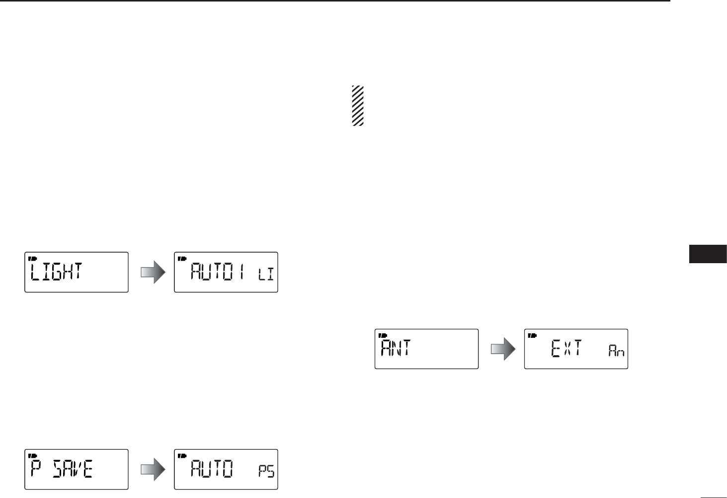
46
9
SET MODE
9
D Display backlighting
The receiver has a backlit display with a 5 seconds timer, for
dim light operation. The backlighting can be turned ON con-
tinuously or turned OFF, if desired.
• OFF : Never lights.
• ON :
Lights continuously while receiver power is ON.
• AUTO1
: Lights when an operation is performed, goes
out after 5 seconds. (default)
• AUTO2
:
Lights when an operation is performed, goes out
after 5 seconds. However, while operating with an
external DC power source, the backlight stays ON.
D Power save
The power save function reduces the current drain to con-
serve battery power. This power save function can be turned
OFF, if desired.
In the default setting (“ON”), the power save function is acti-
vated in 1:4 (125 msec.: 500 msec.) ratio when no signal is
received for 5 seconds. The ratio becomes 1:8 (125 msec.: 1
sec.) when no signal is received for another 60 seconds.
D Antenna selection
This item appears only when accessing the Set mode
in the AM or FM broadcast band mode (frequencies
may differ, depending on the receiver version.
)
Independently select the antenna to use for AM or FM
broadcast band reception.
• EXT : Uses the antenna connected to the antenna con-
nector. (default)
• BAR : Uses the internal bar antenna for the AM broad-
cast band reception. (This selection appears
only when accessing the Set mode in the AM
broadcast band mode.)
• EAR : Uses the connected earphone’s wire as the
antenna for FM broadcast band reception. (This
selection appears only when accessing the Set
mode in the FM broadcast band mode.)
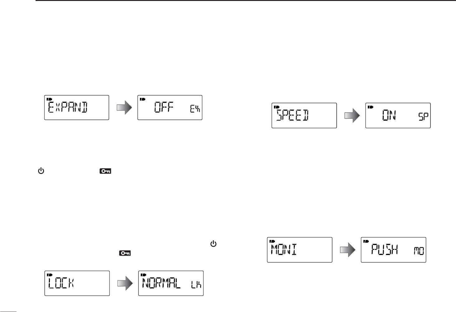
47
9SET MODE
D Expand set mode
Turn the Expand set mode ON or OFF.
• OFF : Displays only the regular set mode. (default)
• ON :
Displays the regular set mode and the expand
set mode.
D Key lock effect
Even while the key lock function is ON, [Y]/[Z] and [SQL]
can still be usable. Usable switches can be set to one of 4
groups.
[] and [FUNC]+[ ](BAND) are also usable during the
locked state, however, these switches are not effected by
this setting.
• NORMAL : [Y]/[Z] and [SQL] are accessible. (default)
• NO SQL : [SQL] is accessible. (The function of [SQL] is
not locked.)*
• NO VOL : [Y]/[Z] are accessible. (The function of
[Y]/[Z is not locked.)*
• ALL : No key function is usable, except [] and
[FUNC]+[ ](BAND).
*“NO” indicates no lock on the function.
D Dial speed acceleration
The dial speed acceleration automatically speeds up the
tuning dial speed, when rotating [DIAL] rapidly.
• OFF : The dial speed acceleration is turned OFF.
• ON : The dial speed acceleration is tuned ON.
(default)
D Monitor switch action
The monitor switch, [SQL], can be set as a ‘sticky’ switch.
When set to the sticky condition, each push of [SQL] toggles
the monitor function ON or OFF.
• PUSH : Pushing and holding [SQL] to monitor the fre-
quency. (default)
• HOLD :
Push [SQL] momentarily to monitor the fre-
quency and push momentarily again to cancel it
.
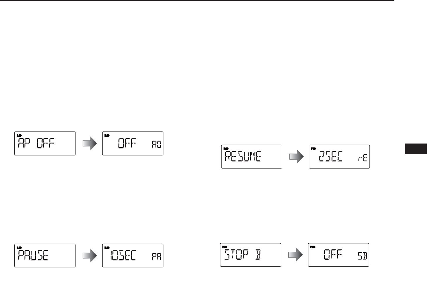
48
9
SET MODE
9
D Auto power OFF
The receiver can be set to automatically turn OFF, and
sound a beep, after a specified period when no key opera-
tions are performed.
OFF (default), times of 30 minutes, 1 hour, 1.5 hours, 2
hours and BUSY can be specified. The (repetitive) period
is retained even when the receiver is turned OFF, even by
the auto power OFF function. To cancel the function, select
“OFF”.
D Scan pause timer
Selects the scan pause time. When receiving signals, the
scan pauses according to the scan pause time.
• 2–20 : The scan pauses for 2–20 seconds on a
received signal, and is selected in 2 second
steps. (default: 10 seconds)
• HOLD : The scan pauses on a received signal until it
disappears. Rotate [DIAL] to resume manually.
D Scan resume timer
Selects the scan resume time. The scan resumes after the
specified period after the received signal disappears.
• 0 : The scan resumes immediately after the
received signal disappears.
• 1–5 : The scan pause 1–5 seconds after the received
signal disappears. (default: 2 seconds)
• HOLD : The scan pauses on the received signal, even
if it disappears. Rotate [DIAL] to resume manu-
ally.
D Scan stop beep
Turns the scan stop beep function ON or OFF (default).
When the function is activated (“ON” is selected), a long
beep will sound each time when signal is received during a
scan.
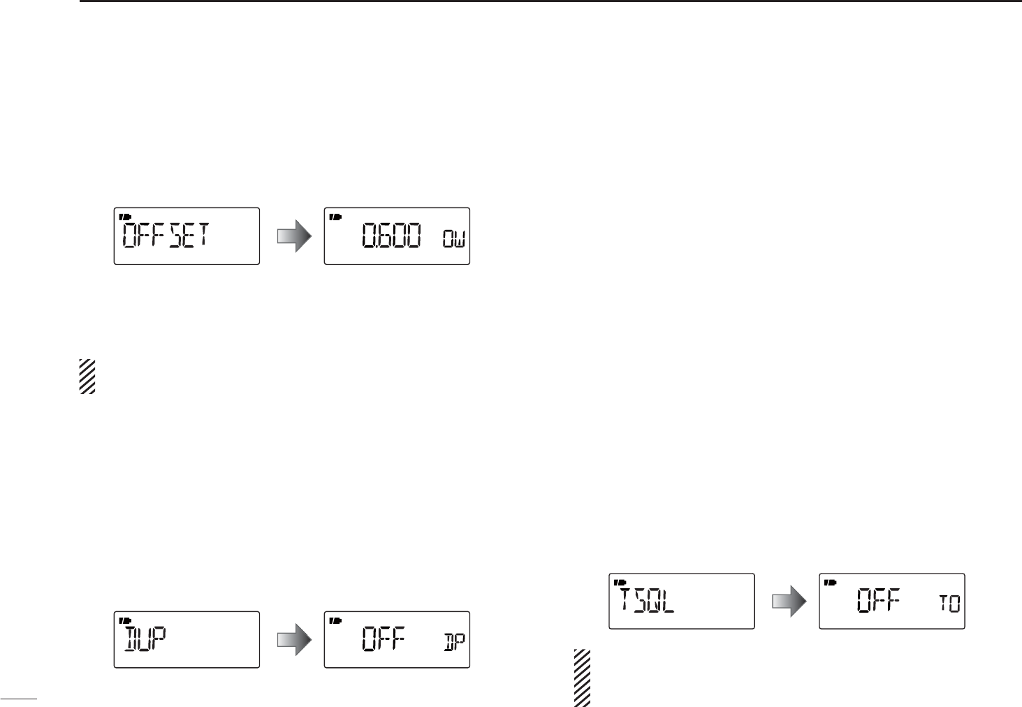
49
9SET MODE
D Frequency offset
Sets the frequency offset for each frequency band independ-
ently within 0 to 159.995 MHz range. During duplex opera-
tion (–DUP or +DUP), the monitoring frequency (while [SQL]
is pushed) shifts the set frequency.
The default value may differ depending on the selected
frequency band, before accessing the Set mode, and the
receiver version.
The selected tuning step in the VFO mode is used for the
frequency offset setting.
D Duplex direction
Selects the duplex direction. The displaying frequency shifts
the programmed frequency in frequency offset above when
monitor function is in use (while holding down [SQL]).
• OFF : Simplex operation. (default)
• –DUP : The displayed frequency shifts down dur-
ing monitor.
• +DUP : The displayed frequency shifts up during
monitor.
D Tone squelch
Selects the tone or DTCS squelch operation and pocket
beep capability, when waiting for a desired signal.
• OFF : Regular noise squelch operation. (default)
• TSQL(( )) : In addition to the “TSQL” setting, alert
beeps will sound when a signal with the
matched subaudible tone is received.
• TSQL : Selects tone squelch. The squelch opens
only when a signal with a matched subaudi-
ble tone is received.
• DTCS(( )) : In addition to the “DTCS” setting, alert
beeps will sound when a signal with a
matched DTCS code is received.
• DTCS : Selects DTCS squelch. The squelch opens
only when a signal with a matched DTCS
code is received.
• TSQL-R : Selects reverse tone squelch. The squelch
becomes mute only when a signal with a
matched subaudible tone is received.
• DTCS-R : Selects
reverse DTCS squelch. The squelch
becomes mute only when a signal with a
matched DTCS code is received.
The subaudible tone frequency is programmed in the tone
frequency and DTCS code is programmed into the DTCS
code option.
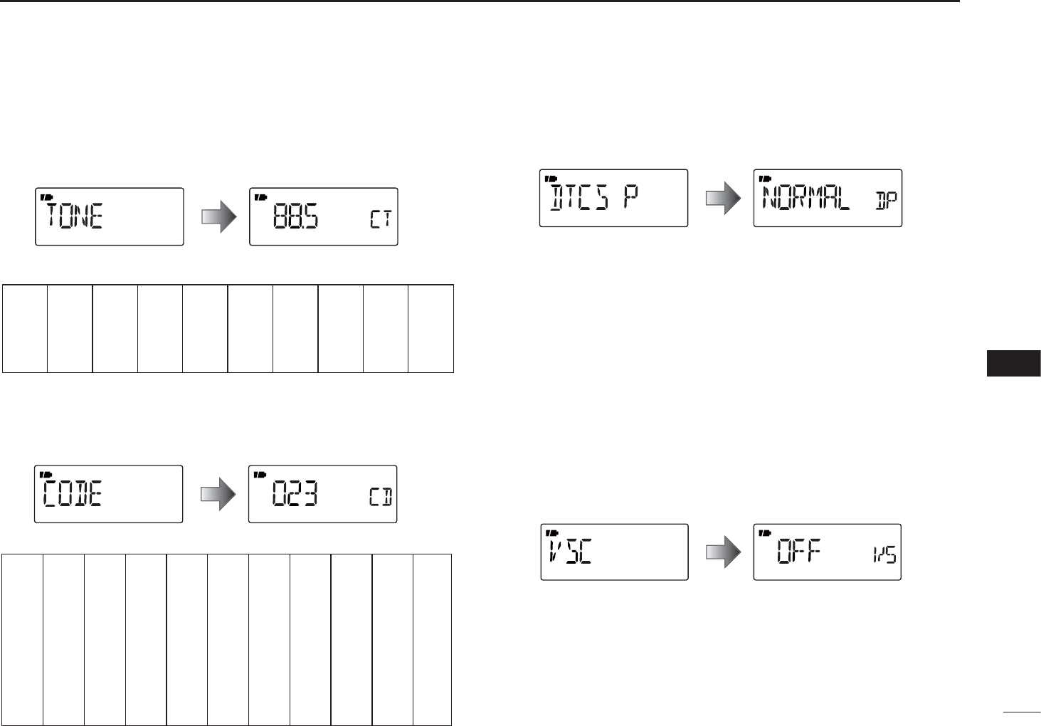
50
9
SET MODE
9
D Tone frequency
Selects a subaudible tone frequency for tone squelch opera-
tion. A total of 50 tone frequencies (67.0–254.1 Hz) are
selectable.(default: 88.5 Hz)
• Available subaudible tone frequencies
67.0
69.3
71.9
74.4
77.0
79.7
82.5
85.4
88.5
91.5
94.8
97.4
100.0
103.5
107.2
110.9
114.8
118.8
123.0
127.3
131.8
136.5
141.3
146.2
151.4
156.7
159.8
162.2
165.5
167.9
171.3
173.8
177.3
179.9
183.5
186.2
189.9
192.8
196.6
199.5
203.5
206.5
210.7
218.1
225.7
229.1
233.6
241.8
250.3
254.1
D DTCS code
Selects a DTCS code for DTCS squelch operation. A total of
104 codes (023–754) are selectable. (default: 023)
• Available DTCS code
D DTCS polarity
Selects the DTCS polarity between normal and reverse.
(default: NORMAL)
D VSC
This function is useful when you don’t want unmodulated
signals pausing a scan. When the voice squelch control
function is activated, the receiver checks received signals
for voice components. If a received signal includes voice
components, and the tone of the voice components changes
within 1 second, scan pauses (or stops). If the received
signal includes no voice components or the tone of the
voice components does not change within 1 second, scan
resumes.
(default: OFF)
023
025
026
031
032
036
043
047
051
053
125
131
132
134
143
145
152
155
156
162
245
246
251
252
255
261
263
265
266
271
356
364
365
371
411
412
413
423
431
432
506
516
523
526
532
546
565
606
612
624
054
065
071
072
073
074
114
115
116
122
165
172
174
205
212
223
225
226
243
244
274
306
311
315
325
331
332
343
346
351
445
446
452
454
455
462
464
465
466
503
627
631
632
654
662
664
703
712
723
731
732
734
743
754
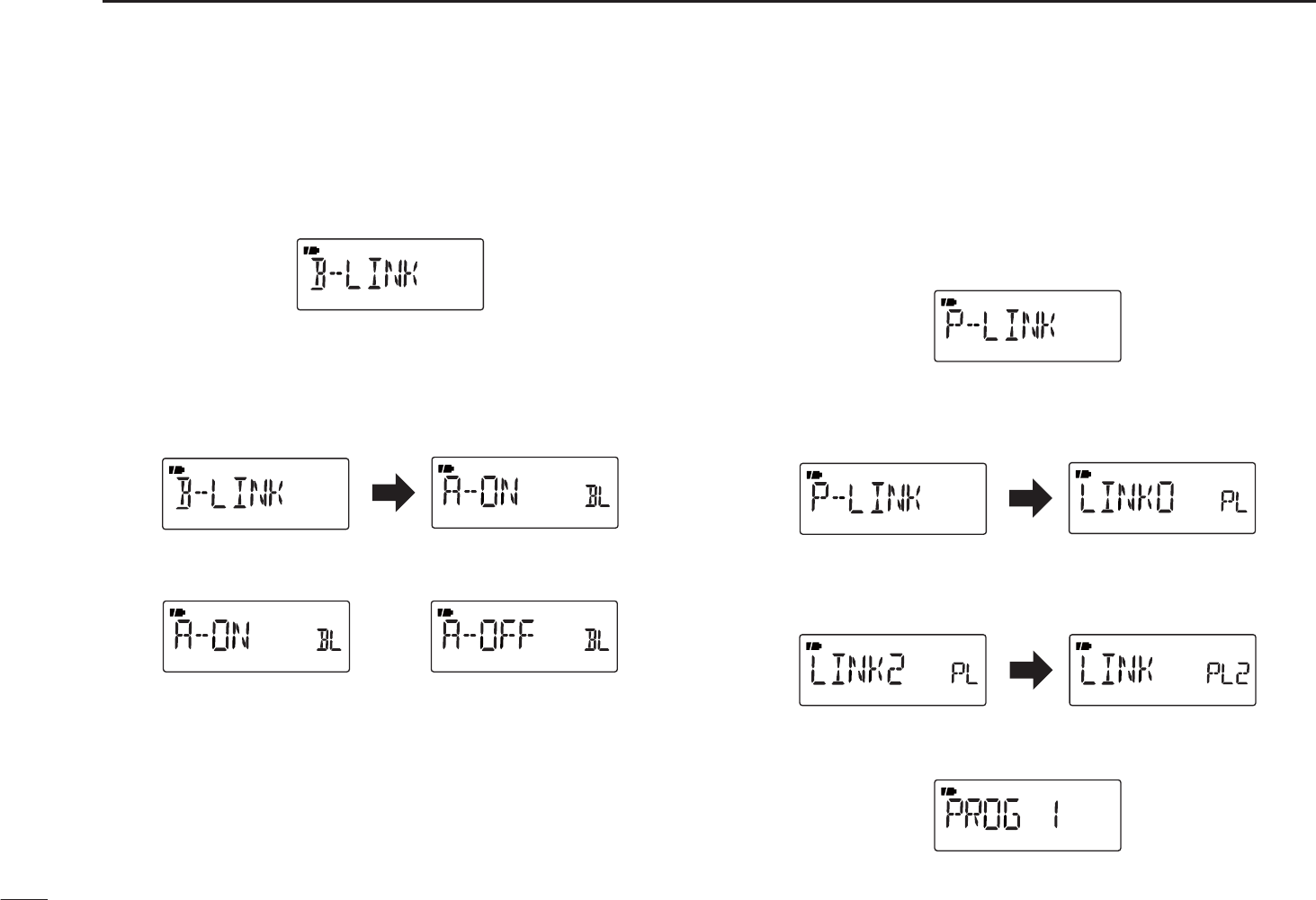
51
9SET MODE
D Memory bank link function (B-LINK)
Turns the memory bank link function ON (default) or OFF.
The link function provides continuous bank scan, scanning
all channels in the selected banks during bank scan.
• Bank link setting
qPush [MODE] to enter the bank link setting mode.
wRotate [DIAL] to select a bank that you want to change
the link setting.
eWhile holding down [FUNC], rotate [DIAL] to set the link
setting ON or OFF.
Setting is ON Setting is OFF
rRepeat steps w and e until the bank link setting is fin-
ished.
tPush [TS] to exit the bank link setting mode.
D Program scan link function (P-LINK)
Sets the program scan link function. During program scan,
link function performs a continuous program scan in the se-
lected program scan number during program scan.
Default settings for LINK0 to LINK9;
PROG 1 to PROG 24 are linked, but PROG 0 is not linked.
• Confirming program scan link
qPush to [MODE] to enter the program scan link setting.
wRotate [DIAL] to select the program scan link number
that you want to confirm, then push [MODE].
• “LINK” appears.
ePush [MODE], then rotate [DIAL] to confirm the linked
program scans.
rPush [TS] three times to exit the program scan link setting.
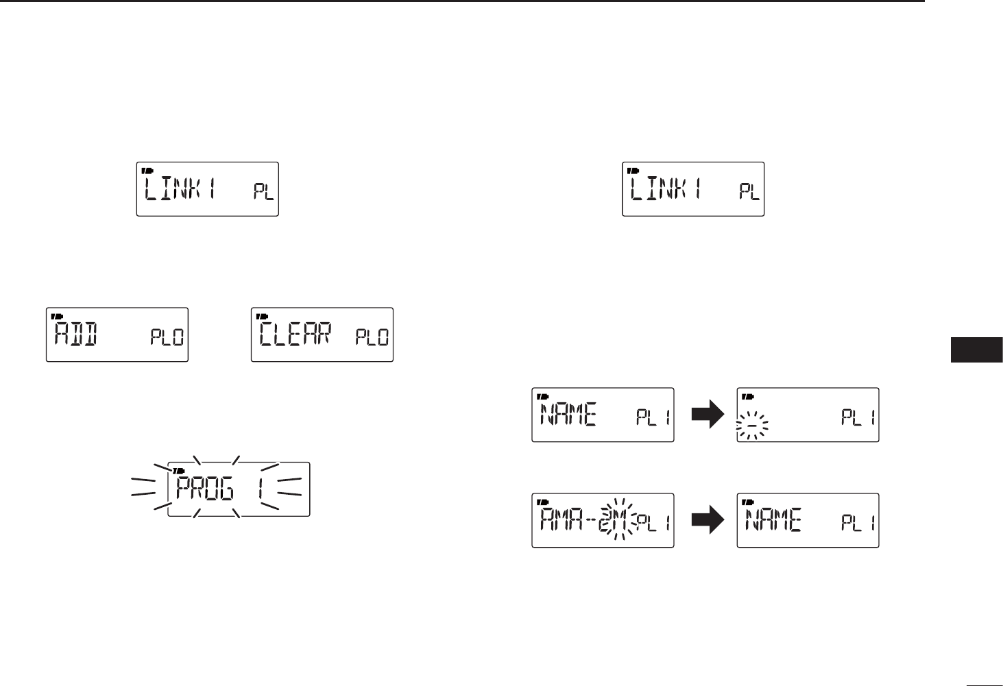
52
9
SET MODE
1
2
3
4
5
6
7
8
9
10
11
12
13
14
15
16
• Program scan link setting
qPush to [MODE] to enter the program scan link setting.
wRotate [DIAL] to select the program scan link number
that you want to change.
ePush [MODE], then rotate [DIAL] to select the option,
“ADD” or “CLEAR”.
rRotate [DIAL] to select the desired program scan.
• When “ADD” is selected in step e, only non-linked pro-
gram scans are displayed. When “CLEAR” is selected in
step e, only linked program scans are displayed.
tPush [MODE] to set the program scan link setting.
yRepeat steps r and t to add or clear the program scan
to or from the link, or push [TS] twice to exit the program
scan link setting.
• Program scan link name programming
qPush to [MODE] to enter the program scan link setting.
wRotate [DIAL] to select the program scan link number
that you want to change.
ePush [MODE], then rotate [DIAL] to select “NAME.”
rPush [MODE] to enter the name programming.
tWhile holding down [FUNC], rotate [DIAL] to select the
desired character, number, symbol or space.
• Rotate [DIAL] right or left to move the cursor right or
left, respectively.
yWhen finishing entering a name, push [MODE] to set the
name and then exit the name programming.
uPush [TS] twice to exit the program scan link setting.
i Push [TS] to exit the Set mode.
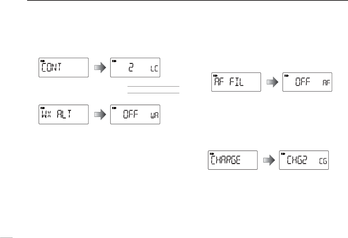
53
9SET MODE
D LCD contrast
Selects the LCD contrast level between 1 (light) and 5 (dark),
as desired.
(default: 3)
D Weather alert function U.S.A. version only
Turns the weather alert function ON or OFF.
D AF filter
The AF filter suppresses high-pitch tone when this setting is
ON. This function can be set for AM and WFM mode, but it
does not appear for FM mode. Default setting for AM mode
is “ON,” and for WFM mode is “OFF.”
D Charge
Select the CHG1 or CHG2 charge, which will be activated
after the charge timer ends. (default: CHG2)
• CHG1 :
Stops charging after 15 hours have passed.
• CHG2 : Continues to trickle charge the battery,
even after 15 hours have passed.
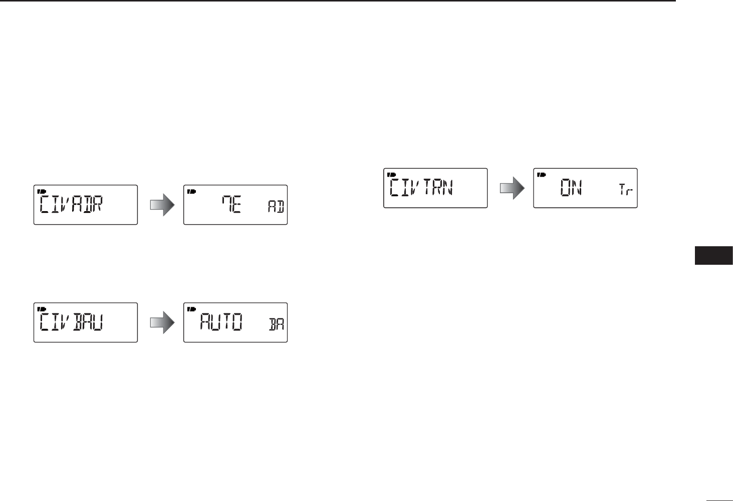
54
9
SET MODE
1
2
3
4
5
6
7
8
9
10
11
12
13
14
15
16
54
9
10
D CI-V Address
To distinguish equipments, each CI-V transceiver/receiver
has its own Icom standard address in hexadecimal number.
The IC-R6’s address is “7E.”
When 2 or more IC-R6 receivers are connected with an op-
tional CT-17 CI-V level converter, set a different address for
each of them in the range “01” to “DF.” (default: 7E)
D CI-V baud rate
Sets the baud rate. When “AUTO” is selected, the baud rate
is automatically set according to the connected controller or
other Icom CI-V radio. (default: AUTO)
D CI-V transceiver
CI-V transceive operation is possible even if the IC-R6 re-
ceiver is connected to an Icom CI-V radio. When set to “ON”,
the frequency and the operating mode of the IC-R6 automat-
ically change to those of connected radios, and vice versa.
(default: ON)
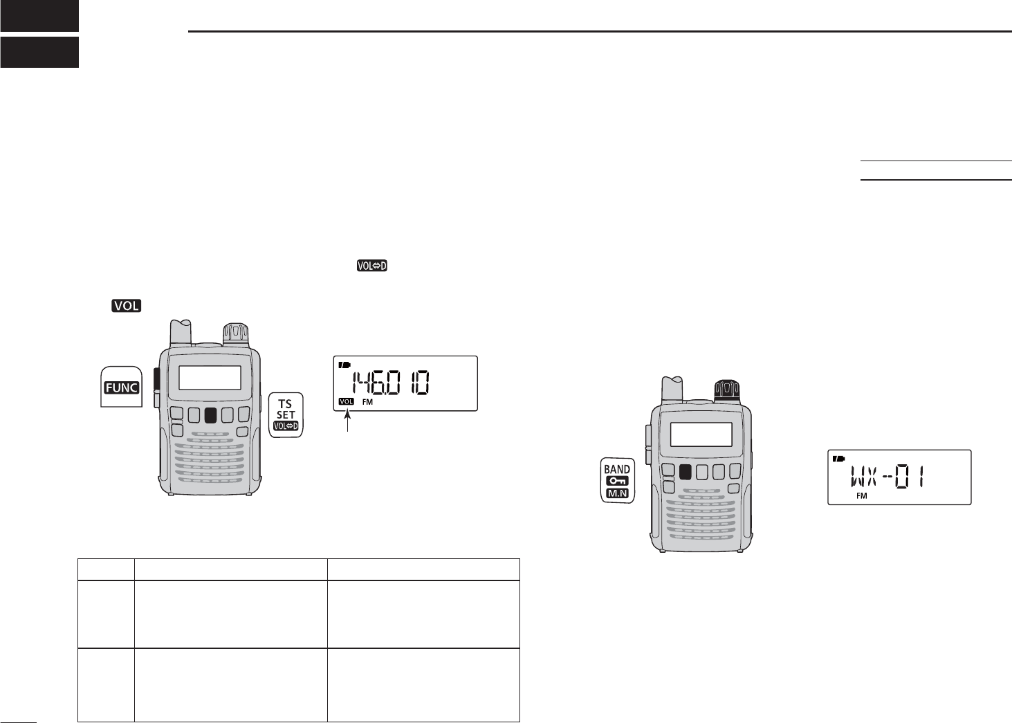
55
OTHER FUNCTIONS
10
N [DIAL] function assignment
The [DIAL] control can be used as an audio volume control,
instead of
[Y]/[Z]
keys. However, while [DIAL] functions as
an audio volume control, the
[Y]/[Z]
keys function as tuning
controls.
±
While holding down [FUNC], push
[ ]
(TS) to toggle the
[DIAL] function between tuning dial and audio volume.
•
“ ” icon appears when [DIAL] functions as the volume control.
“VOL” appears while
[DIAL] functions as the
audio volume control.
• [DIAL] and [Y]/[Z]
]
functions
N Weather channel operation
U.S.A. version only
D Weather channel selection
q Push [V/M] to select the VFO mode, if any other mode is
selected.
w While holding down [BAND], rotate [DIAL] to select the
weather channel group.
• The weather channel group can also be selected by pushing
[BAND] repeatedly.
eRotate [DIAL] to select a desired weather channel.
[DIAL]
Weather channel display
r Push [BAND] to change frequency band, or push [V/M] to
select the memory mode.
No “VOL” icon “VOL” appears
Frequency, Memory channel,
Audio volume
[DIAL] Squelch level, Scanning
direction, Set mode item
and condition set
Audio volume set
Frequency, Memory channel,
[Y]/[Z]Squelch level, Scanning
direction, Set mode item
and condition set
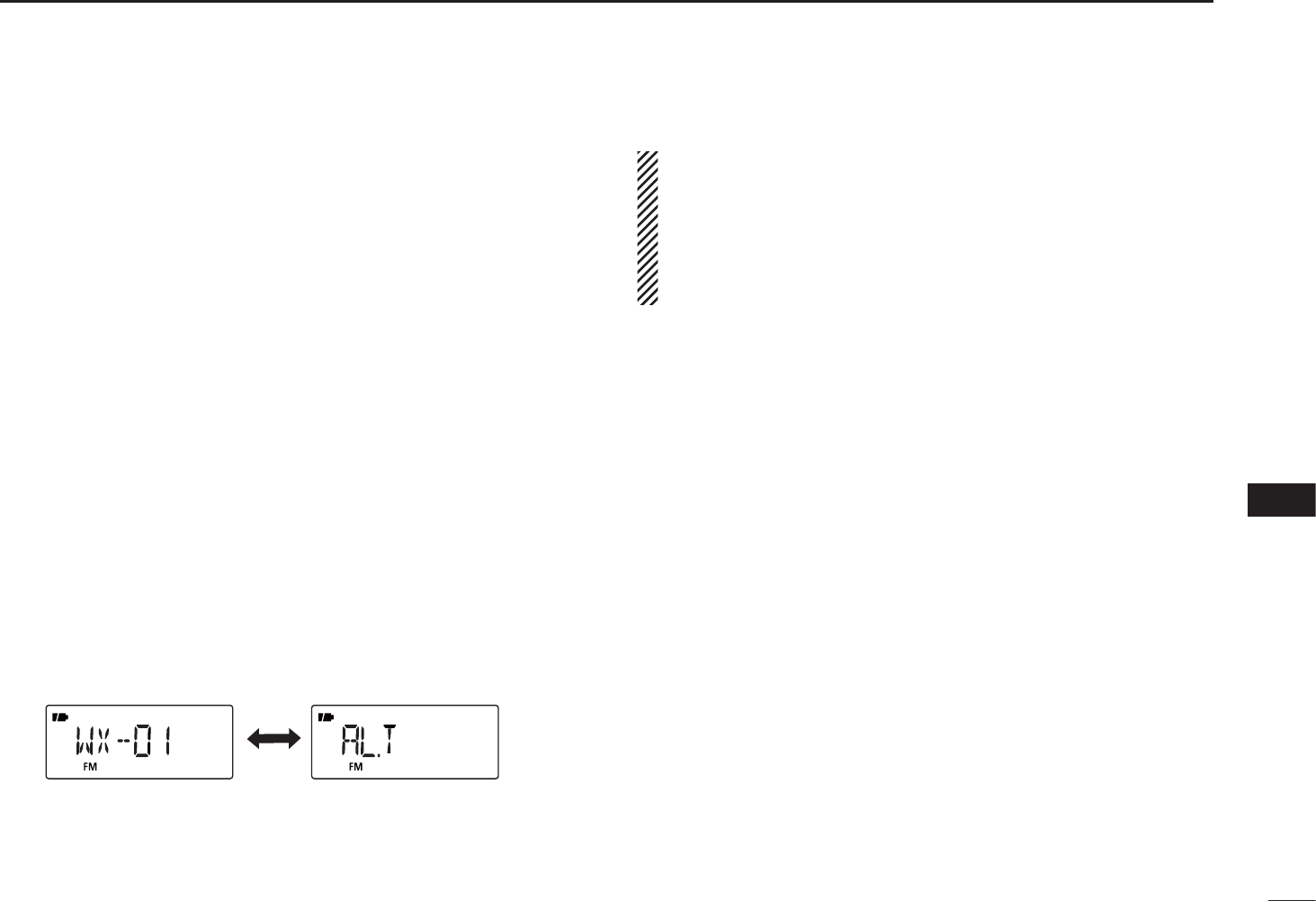
56
10
OTHER FUNCTIONS
1
2
3
4
5
6
7
8
9
10
11
12
13
14
15
16
D Weather alert function
NOAA broadcast stations transmit weather alert tones
before important weather announcements. When the weath-
er alert function is turned ON, the selected weather channel
is monitored every 5 seconds for the announcement. When
the alert signal is detected, the “ALT” and the WX channel
are displayed alternately and a beep tone sounds until the
receiver is operated. The previously selected (used) weather
channel is checked periodically during standby, or while
scanning.
qSelect a desired weather channel.
wTurn the weather alert function ON in the Set mode.
± Push [SET](TS) to enter the Set mode.
±Rotate [DIAL] to select the weather alert option. Then,
while holding down [FUNC], rotate [DIAL] to set “ON”.
± Push [SET](TS) to exit the Set mode.
eSet a desired stand-by condition.
• Select the VFO or a memory channel.
• Scan or priority watch operation can also be selected.
r When the alert is detected, a beep sounds and the follow-
ing indicator will be displayed.
The above icons are alternately displayed.
t Turn the weather alert function OFF in the Set mode.
NOTE: While receiving a signal (on a frequency other
than the weather alert ON frequency), the receiving signal
or audio will be interrupted momentarily every 5 seconds
(approx.)
when the alert function is turned ON. This is
caused by the WX alert function. To eliminate the interrup-
tion, set the weather alert item OFF in the Set mode.
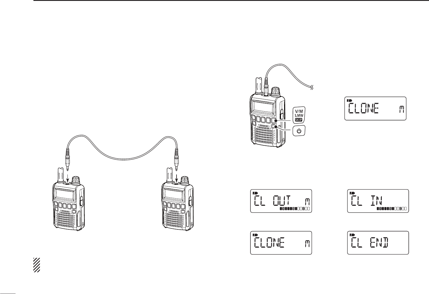
57
10 OTHER FUNCTIONS
N Data cloning
Cloning allows you to quickly and easily transfer the pro-
grammed contents from one receiver to another; or data
from a personal computer to a receiver, using the optional
CS-R6 CLONING SOFTWARE.
DCloning between receivers
q Connect the OPC-474 cloning cable to the [SP] jack of the
master and sub-receivers.
• The master receiver is used to send data to the sub-receiver.
to [SP]
Master
receiver
Sub
receiver
to [SP]
NOTE: DO NOT push any key on the sub-receiver during
cloning. This will cause a cloning error.
w While holding down [V/M], turn only the master receiver
power ON, to enter the cloning mode (master receiver only—
power ON only for sub-receiver).
Master receiver
“CLONE” and “m” appear
when entered the cloning
mode.
e Push [SQL] on the master receiver.
• The receiver displays the following.
During cloning
After cloning
Master receiver display Sub-receiver display
r When cloning is finished, turn power OFF, then ON to exit
the cloning mode.
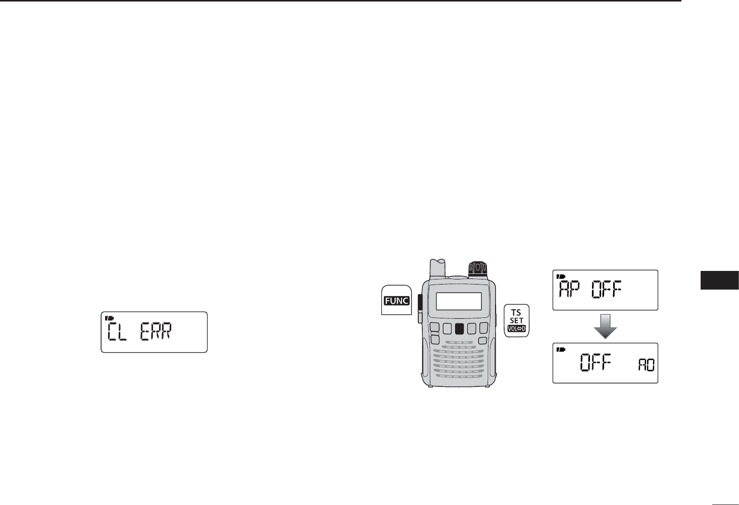
58
10
OTHER FUNCTIONS
10
DCloning using a personal computer
Data can be cloned to and from a personal computer
(Microsoft® Windows® 2000/XP/Windows Vista® or Windows 7)
using the optional CS-R6 CLONING SOFTWARE and the option-
al OPC-478/OPC-478UC CLONING CABLE. Consult the CS-R6
CLONING SOFTWARE HELP file for details.
DCloning error
)NOTE: DO NOT push any key on the sub-receiver during
cloning. This will cause a cloning error.
When the display appears as below, a cloning error has
occurred.
In such a case, both receivers automatically return to the
clone standby condition and cloning must be repeated.
N Auto power-off function
The IC-R6 can be set to automatically turn OFF after a
specified period in which no operation is performed.
120, 90, 60, 30 minutes and OFF can be specified. The
specified period is retained even when the receiver is turned
OFF by the auto power-off function. To cancel the function,
select “OFF” in step e below.
qPush [SET](TS) for 1 second to enter the Set mode.
wRotate [DIAL] to select the “AP OFF” item.
• Turn the Expand set mode ON for selection. (p. 39)
[DIAL]
e While holding down [FUNC], rotate [DIAL] to select a
desired time or to turn the function OFF.
rPush [SET](TS) to exit the Set mode.
Microsoft, Windows and Windows Vista are registered trademarks of Microsoft
Corporation in the U.S.A. and other countries.
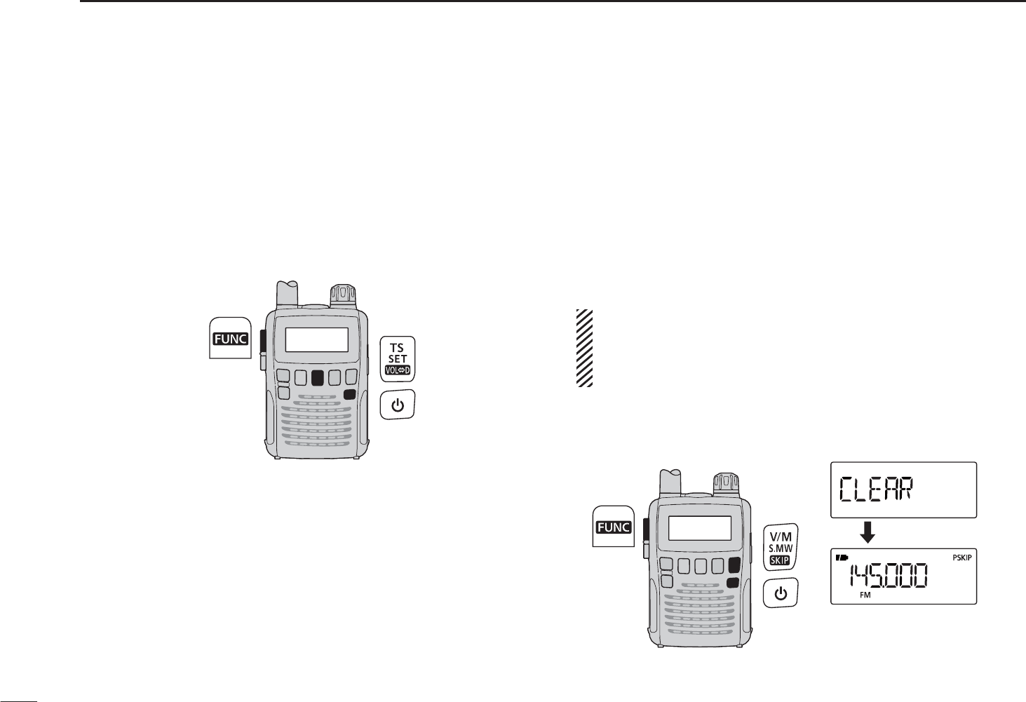
59
10 OTHER FUNCTIONS
N Partial reset
If you want to initialize the operating settings (VFO frequen-
cy, VFO settings, Set mode contents) without clearing the
memory contents, a partial resetting function is available for
the receiver.
±While holding down [FUNC] and [TS], turn the power ON
to partially reset the receiver.
N All reset
The function display may occasionally display erroneous
information (e.g. when first applying power). This may be
caused externally by static electricity or by other factors.
If this problem occurs, turn power OFF. After waiting a few
seconds, turn power ON again. If the problem persists, per-
form the following procedure.
• Partial resetting is also available. See to the left for details.
IMPORTANT!:
Resetting the receiver CLEARS all memory informa-
tion and initializes all values in the receiver, including TV
channel skip setting.
±While holding down [FUNC] and [Z], turn the power ON
to reset the CPU.
*The appearing frqeuency
is differ according to
receiver version.
±While holding down [FUNC] and [TS], turn the power
OFF, then ON again to partially reset the receiver.

60
11
FREQUENCY TABLE
10
11
N TV channels
The following tables show the channels versus
video and audio frequencies, depending on
each version.
D U.S.A. channels (unit: MHz)
CH Freq.
2 59.75
3 65.75
4 71.75
5 81.75
6 87.75
7 179.75
8 185.75
9 191.75
10 197.75
11 203.75
12 209.75
13 215.75
14 475.75
15 481.75
16 487.75
17 493.75
18 499.75
19 505.75
20 511.75
21 517.75
22 523.75
23 529.75
24 535.75
25 541.75
26 547.75
CH Freq.
27 553.75
28 559.75
29 565.75
30 571.75
31 577.75
32 583.75
33 589.75
34 595.75
35 601.75
36 607.75
37 613.75
38 619.75
39 625.75
40 631.75
41 637.75
42 643.75
43 649.75
44 655.75
45 661.75
46 667.75
47 673.75
48 679.75
49 685.75
50 691.75
51 697.75
CH Freq.
52 703.75
53 709.75
54 715.75
55 721.75
56 727.75
57 733.75
58 739.75
59 745.75
60 751.75
61 757.75
62 763.75
63 769.75
64 775.75
65 781.75
66 787.75
67 793.75
68 799.75
69 805.75
D CCIR channels (unit: MHz)
CH Freq.
1 46.75
2 53.75
3 60.75
4 67.75
5 180.75
6 187.75
7 194.75
8 201.75
9 208.75
10 215.75
11 222.75
12 229.75
21 476.75
22 484.75
23 492.75
24 500.75
25 508.75
26 516.75
27 524.75
28 532.75
29 540.75
30 548.75
31 556.75
32 564.75
33 572.75
34 580.75
35 588.75
36 596.75
37 604.75
38 612.75
39 620.75
CH Freq.
40 628.75
41 636.75
42 644.75
43 652.75
44 660.75
45 668.75
46 676.75
47 684.75
48 692.75
49 700.75
50 708.75
51 716.75
52 724.75
53 732.75
54 740.75
55 748.75
56 756.75
57 764.75
58 772.75
59 780.75
60 788.75
61 796.75
62 804.75
63 812.75
64 820.75
65 828.75
66 836.75
67 844.75
68 852.75
69 860.75
D Australian channels
(unit: MHz)
CH Freq.
0 51.75
1 62.75
2 69.75
3 91.75
4 100.75
5 107.75
5A 143.75
6 180.75
7 187.75
8 194.75
9 201.75
10 214.75
11 221.75
28 532.75
29 539.75
30 546.75
31 553.75
32 560.75
33 567.75
34 574.75
35 581.75
36 588.75
37 595.75
38 602.75
39 609.75
40 616.75
41 623.75
42 630.75
CH Freq.
43 637.75
44 644.75
45 651.75
46 658.75
47 665.75
48 672.75
49 679.75
50 686.75
51 693.75
52 700.75
53 707.75
54 714.75
55 721.75
56 728.75
57 735.75
58 742.75
59 749.75
60 756.75
61 763.75
62 770.75
63 777.75
64 784.75
65 791.75
66 798.75
67 805.75
68 812.75
69 819.75

61
11 FREQUENCY TABLE
D China channels (unit: MHz)
CH Freq.
1 56.25
2 64.25
3 72.25
4 83.75
5 91.75
6 174.75
7 182.75
8 190.75
9 198.75
10 206.75
11 214.75
12 222.75
13 477.75
14 485.75
15 493.75
16 501.75
17 509.75
18 517.75
19 525.75
20 533.75
21 541.75
22 549.75
23 557.75
24 565.75
25 613.75
26 621.75
27 629.75
28 637.75
29 645.75
30 653.75
31 661.75
CH Freq.
32 669.75
33 677.75
34 685.75
35 693.75
36 701.75
37 709.75
38 717.75
39 725.75
40 733.75
41 741.75
42 749.75
43 757.75
44 765.75
45 773.75
46 781.75
47 789.75
48 797.75
49 805.75
50 813.75
51 821.75
52 829.75
53 837.75
54 845.75
55 853.75
56 861.75
57 869.75
58 877.75
59 885.75
60 893.75
61 901.75
62 909.75
CH Freq.
63 917.75
64 925.75
65 933.75
66 941.75
67 949.75
68 957.75
DNew
Zealand
channels
(unit: MHz)
CH Freq.
1 50.75
2 60.75
3 67.75
4 180.75
5 187.75
6 194.75
7 201.75
8 208.75
9 215.75
10 222.75
11 229.75
D UK channels (unit: MHz)
CH Freq.
21 477.25
22 485.25
23 493.25
24 501.25
25 509.25
26 517.25
27 525.25
28 533.25
29 541.25
30 549.25
31 557.25
32 565.25
33 573.25
34 581.25
35 589.25
36 597.25
37 605.25
38 613.25
39 621.25
40 629.25
41 637.25
42 645.25
43 653.25
44 661.25
45 669.25
46 677.25
47 685.25
48 693.25
49 701.25
50 709.25
51 717.25
CH Freq.
52 725.25
53 733.25
54 741.25
55 749.25
56 757.25
57 765.25
58 773.25
59 781.25
60 789.25
61 797.25
62 805.25
63 813.25
64 821.25
65 829.25
66 837.25
67 845.25
68 853.25
69 861.25
D French channels (unit: MHz)
CH Freq.
2 49.25
3 54.00
4 57.25
5 182.50
6 190.50
7 198.50
8 206.50
9 214.50
10 222.50
21 477.75
22 485.75
23 493.75
24 501.75
25 509.75
26 517.75
27 525.75
28 533.75
29 541.75
30 549.75
31 557.75
32 565.75
33 573.75
34 581.75
35 589.75
36 597.75
37 605.75
38 613.75
39 621.75
40 629.75
41 637.75
42 645.75
CH Freq.
43 653.75
44 661.75
45 669.75
46 677.75
47 685.75
48 693.75
49 701.75
50 709.75
51 717.75
52 725.75
53 733.75
54 741.75
55 749.75
56 757.75
57 765.75
58 773.75
59 781.75
60 789.75
61 797.75
62 805.75
63 813.75
64 821.75
65 829.75
66 837.75
67 845.75
68 853.75
69 861.75

62
11
FREQUENCY TABLE
11
D Indonesian channels
(unit: MHz)
CH Freq.
2 53.75
3 60.75
4 67.75
5 180.75
6 187.75
7 194.75
8 201.75
9 208.75
10 215.75
11 222.75
12 229.75
21 476.75
22 484.75
23 492.75
24 500.75
25 508.75
26 516.75
27 524.75
28 532.75
29 540.75
30 548.75
31 556.75
32 564.75
33 572.75
34 580.75
35 588.75
36 596.75
37 604.75
38 612.75
39 620.75
CH Freq.
40 628.75
41 636.75
42 644.75
43 652.75
44 660.75
45 668.75
46 676.75
47 684.75
48 692.75
49 700.75
50 708.75
51 716.75
52 724.75
53 732.75
54 740.75
55 748.75
56 756.75
57 764.75
58 772.75
59 780.75
60 788.75
61 796.75
62 804.75
63 812.75
64 820.75
65 828.75
66 836.75
67 844.75
68 852.75
69 860.75
D Italian channels (unit: MHz)
CH Freq.
A 59.25
B 67.75
C 87.75
D 180.75
E 188.75
F 197.75
G 206.75
H 215.75
H1 222.75
H2 229.75
21 476.75
22 484.75
23 492.75
24 500.75
25 508.75
26 516.75
27 524.75
28 532.75
29 540.75
30 548.75
31 556.75
32 564.75
33 572.75
34 580.75
35 588.75
36 596.75
37 604.75
38 612.75
39 620.75
40 628.75
41 636.75
CH Freq.
42 644.75
43 652.75
44 660.75
45 668.75
46 676.75
47 684.75
48 692.75
49 700.75
50 708.75
51 716.75
52 724.75
53 732.75
54 740.75
55 748.75
56 756.75
57 764.75
58 772.75
59 780.75
60 788.75
61 796.75
62 804.75
63 812.75
64 820.75
65 828.75
66 836.75
67 844.75
68 852.75
69 860.75
D Taiwan channels
(unit: MHz)
CH Freq.
7 179.75
8 185.75
9 191.75
10 197.75
11 203.75
12 209.75
D FOT channels
(unit: MHz)
CH Freq.
4 181.75
5 189.75
6 197.75
7 205.75
8 213.75
9 221.75

63
11 FREQUENCY TABLE
N VHF marine channels (unit: MHz)
CH Ship Ship
No. Transmit Receive
01 156.050 160.650
01A 156.050 156.050
02 156.100 160.700
03 156.150 160.750
03A 156.150 156.150
04 156.200 160.800
04A 156.200 156.200
05 156.250 160.850
05A 156.250 156.250
06 156.300 156.300
07 156.350 160.950
07A 156.350 156.350
08 156.400 156.400
09 156.450 156.450
10 156.500 156.500
11 156.550 156.550
12 156.600 156.600
13 156.650 156.650
14 156.700 156.700
15 156.750 156.750
16 156.800 156.800
17 156.850 156.850
18 156.900 161.500
18A 156.900 156.900
19 156.950 161.550
19A 156.950 156.950
20 157.000 161.600
20A 157.000 157.000
21 157.050 161.650
WX CH Frequency
01 162.550
02 162.400
03 162.475
04 162.425
05 162.450
06 162.500
07 162.525
08 161.650
09 161.775
10 163.275
CH Ship Ship
No. Transmit Receive
21A 157.050 157.050
21b 161.650 161.650
22 157.100 161.700
22A 157.100 157.100
23 157.150 161.750
23A 157.150 157.150
24 157.200 161.800
25 157.250 161.850
25b 161.850 161.850
26 157.300 161.900
27 157.350 161.950
28 157.400 162.000
28b 162.000 162.000
60 156.025 160.625
61 156.075 160.675
61A 156.075 156.075
62 156.125 160.725
62A 156.125 156.125
63 156.175 160.775
63A 156.175 156.175
64 156.225 160.825
64A 156.225 156.225
65 156.275 160.875
65A 156.275 156.275
66 156.325 160.925
66A 156.325 156.325
67 156.375 156.375
68 156.425 156.425
69 156.475 156.475
CH Ship Ship
No. Transmit Receive
70 156.525 156.525
71 156.575 156.575
72 156.625 156.625
73 156.675 156.675
74 156.725 156.725
77 156.875 156.875
78 156.925 161.525
78A 156.925 156.925
79 156.975 161.575
79A 156.975 156.975
80 157.025 161.625
80A 157.025 157.025
81 157.075 161.675
81A 157.075 157.075
82 157.125 161.725
82A 157.125 157.125
83 157.175 161.775
83A 157.175 157.175
83b 161.775 161.775
84 157.225 161.825
84A 157.225 157.225
85 157.275 161.875
85A 157.275 157.275
86 157.325 161.925
86A 157.325 157.325
87 157.375 161.975
87A 157.375 157.375
88 157.425 162.025
88A 157.425 157.425
N Weather channels (unit: MHz)

64
11
FREQUENCY TABLE
11
N Other communications in the USA
Dot color Frequency
Red 151.625 MHz
Purple 151.955 MHz
Blue 154.570 MHz
Green 154.600 MHz
White 462.575 MHz
Black 462.625 MHz
Orange 462.675 MHz
Brown 464.500 MHz
Yellow 464.550 MHz
“J” Dot 467.763 MHz
“K” Dot 467.813 MHz
Silver Star 467.850 MHz
Gold Star 467.875 MHz
Red Star 467.900 MHz
Blue Star 467.925 MHz
DBRS (Business Radio
Service) channels
Transceiver Transceiver
Receive transmit
462.5500 MHz 467.5500 MHz
462.5625 MHz
462.5750 MHz 467.5750 MHz
462.5875 MHz
462.6000 MHz 467.6000 MHz
462.6125 MHz
462.6250 MHz 467.6250 MHz
462.6375 MHz
462.6500 MHz 467.6500 MHz
462.6625 MHz
462.6750 MHz 467.6750 MHz
462.6875 MHz
462.7000 MHz 467.7000 MHz
462.7125 MHz
462.7250 MHz 467.7250 MHz
DGMRS (General Mobile
Radio Service) channels
CH Frequency
1 151.820 MHz
2 151.880 MHz
3 151.940 MHz
4 154.570 MHz
5 154.600 MHz
DMURS channels
CH Frequency
1 26.965 MHz
2 26.975 MHz
3 26.985 MHz
4 27.005 MHz
5 27.015 MHz
6 27.025 MHz
7 27.035 MHz
8 27.055 MHz
9 27.065 MHz
10 27.075 MHz
11 27.085 MHz
12 27.105 MHz
13 27.115 MHz
14 27.125 MHz
15 27.135 MHz
16 27.155 MHz
17 27.165 MHz
18 27.175 MHz
19 27.185 MHz
20 27.205 MHz
D HF CB (Citizens Band) channels
CH Frequency
21 27.215 MHz
22 27.225 MHz
23 27.255 MHz
24 27.235 MHz
25 27.245 MHz
26 27.265 MHz
27 27.275 MHz
28 27.285 MHz
29 27.295 MHz
30 27.305 MHz
31 27.315 MHz
32 27.325 MHz
33 27.335 MHz
34 27.345 MHz
35 27.355 MHz
36 27.365 MHz
37 27.375 MHz
38 27.385 MHz
39 27.395 MHz
40 27.405 MHz
CH Frequency
1 462.5625 MHz
2 462.5875 MHz
3 462.6125 MHz
4 462.6375 MHz
5 462.6625 MHz
6 462.6875 MHz
7 462.7125 MHz
DFRS (Family Radio Service) channels
CH Frequency
8 467.5625 MHz
9 467.5875 MHz
10 467.6125 MHz
11 467.6375 MHz
12 467.6625 MHz
13 467.6875 MHz
14 467.7125 MHz

65
11 FREQUENCY TABLE
Frequency Description
121.500 Emergencies
122.000 Flight Advisory Service
122.200 Flight Service Stations
122.700 Unicom— Uncontrolled airports
122.725 Unicom— Private airports
122.750 Unicom— Air-to-air communications
122.800 Unicom— Uncontrolled airports
122.900 Search & rescue training, & uncontrolled airports
122.950 Unicom— Controlled airports
123.000 Unicom— Uncontrolled airports
123.025 Helicopters— Air-to-air communications
123.050 Unicom— Heliports
123.075 Unicom— Heliports
123.100 Search & Rescue
123.300 Flight Schools
123.450 Air-to-air communications (unofficial)
123.500 Flight Schools
123.600 Flight Service Stations— Uncontrolled airports
148.125 Civil Air Patrol Repeaters— Secondary
148.150 Civil Air Patrol Repeaters— Primary
156.300 Aircraft-to-ship— safety
156.400 Aircraft-to-ship— commercial
156.425 Aircraft-to-ship— non-commercial
156.450 Aircraft-to-ship— commercial
156.625 Aircraft-to-ship— non-commercial
156.900 Aircraft-to-ship— commercial
243.000 Military Emergency “Guard”
255.400 Flight Advisory Service
257.800 Civilian Towers
311.000 SAC Primary
321.000 SAC Secondary
381.800 USCG— Primary
D General aviation frequencies
CH
Frequency
Remarks
range
2– 13 54–216 (same as broadcast VHF)
14– 22 120–174 Mid band Ch. A–I
23– 36 216–300 Super band J–W
37– 53 300–402 Hyper band AA–QQ
54– 64 402–468
65– 94 468–648 (Ultra band)
95– 99 90–120 Low band A5–A1
100–125 648–804 (Ultra band)
D Cable TV (IRC) (unit: MHz)
169.445 MHz
169.505 MHz
170.245 MHz
170.305 MHz
171.045 MHz
171.105 MHz
171.845 MHz
171.905 MHz
*Power limited to 1/20 watt. These frequencies are also used at drive-in
windows at some fast-food restaurants.
D Wireless Microphones

66
11
FREQUENCY TABLE
11
N Other communications— other countries
CH Frequency
1 446.00625
2 446.01875
3 446.03125
4 446.04375
5 446.05625
6 446.06875
7 446.08125
8 446.09375
D
PMR446 channels
(unit: MHz)
CH Frequency
59 434.525
60 434.550
61 434.575
62 434.600
63 434.625
64 434.650
65 434.675
66 434.700
67 434.725
68 434.750
69 434.775
CH Frequency
1 433.075
2 433.100
3 433.125
4 433.150
5 433.175
6 433.200
7 433.225
8 433.250
9 433.275
10 433.300
11 433.325
12 433.350
13 433.375
14 433.400
15 433.425
16 433.450
17 433.475
18 433.500
19 433.525
20 433.550
21 433.575
22 433.600
23 433.625
24 433.650
25 433.675
26 433.700
27 433.725
28 433.750
29 433.775
D LPD (Low Power Device) channels (unit: MHz)
CH Frequency
30 433.800
31 433.825
32 433.850
33 433.875
34 433.900
35 433.925
36 433.950
37 433.975
38 434.000
39 434.025
40 434.050
41 434.075
42 434.100
43 434.125
44 434.150
45 434.175
46 434.200
47 434.225
48 434.250
49 434.275
50 434.300
51 434.325
52 434.350
53 434.375
54 434.400
55 434.425
56 434.450
57 434.475
58 434.500

67
11 FREQUENCY TABLE
CH Frequency
1 476.425 MHz
2 476.450 MHz
3 476.475 MHz
4 476.500 MHz
5 476.525 MHz
6 476.550 MHz
7 476.575 MHz
8 476.600 MHz
9 476.625 MHz
10 476.650 MHz
11 476.675 MHz
12 476.700 MHz
13 476.725 MHz
14 476.750 MHz
15 476.775 MHz
16 476.800 MHz
17 476.825 MHz
18 476.850 MHz
19 476.875 MHz
20 476.900 MHz
DUHF C.R.S (Citizen Radio Service) channels
CH Frequency
21 476.925 MHz
22 476.950 MHz
23 476.975 MHz
24 477.000 MHz
25 477.025 MHz
26 477.050 MHz
27 477.075 MHz
28 477.100 MHz
29 477.125 MHz
30 477.150 MHz
31 477.175 MHz
32 477.200 MHz
33 477.225 MHz
34 477.250 MHz
35 477.275 MHz
36 477.300 MHz
37 477.325 MHz
38 477.350 MHz
39 477.375 MHz
40 477.400 MHz

68
12
MAINTENANCE
11
12
PROBLEM POSSIBLE CAUSE SOLUTION REF.
N Troubleshooting If your receiver seems to be malfunctioning, please check
the following points before sending it to a service center.
No power comes on.
No sound comes from the
speaker.
Sensitivity is low and only
strong signals are audible.
Frequency cannot be set.
No beep sound.
Receive audio is distorted.
Desired Set mode item
cannot be selected.
Programmed scan does
not start.
Memory or bank scan
does not start.
Installed batteries cannot
be charged.
• The batteries are exhausted.
• The battery polarity is reversed.
• Volume level is too low.
• Squelch level is set too tight.
• Different tone is selected with tone squelch.
• Attenuator function is activated.
• The lock function is activated.
• Beep tones are turned OFF or the beep tone
level is too low.
• The operating mode is not selected correctly.
• “EXPAND” item is set to OFF.
• Some Set mode items can be selected in the AM
or FM broadcast band only.
• Program scan edges are not programmed.
• No or only one memory or bank channel is
programmed.
• The batteries over discharged.
• Replace the batteries or charge the batteries.
• Check the battery polarity.
• Push
[Y]
to obtain a suitable level.
• While holding down [SQL], rotate [DIAL] to set the
squelch level.
• Turn the appropriate function OFF.
• While holding down [FUNC], push [SQL] to turn
the attenuator function OFF.
• While holding down [FUNC], push [](BAND)
for 1 second to turn the function OFF.
• Turn beep tone ON or set the beep tone level to
appropriate level in the Set mode.
• Push [MODE] repeatedly to select a suitable
operating mode.
• Turn “EXPAND” item ON.
• Choose the AM or FM broadcast band.
• Program a pair of scan edge channels.
• Program at least 2 memory or bank channels
• Re-install the batteries (wait at least for 1 second),
then plug the AC adapter while holding down [FUNC].
pgs. 5, 6
p. 5
p. 11
p. 12
p. 35
p. 13
p. 10
p. 41
p. 12
p. 39
p. 7
p. 27
pgs. 16,
17
p. 6
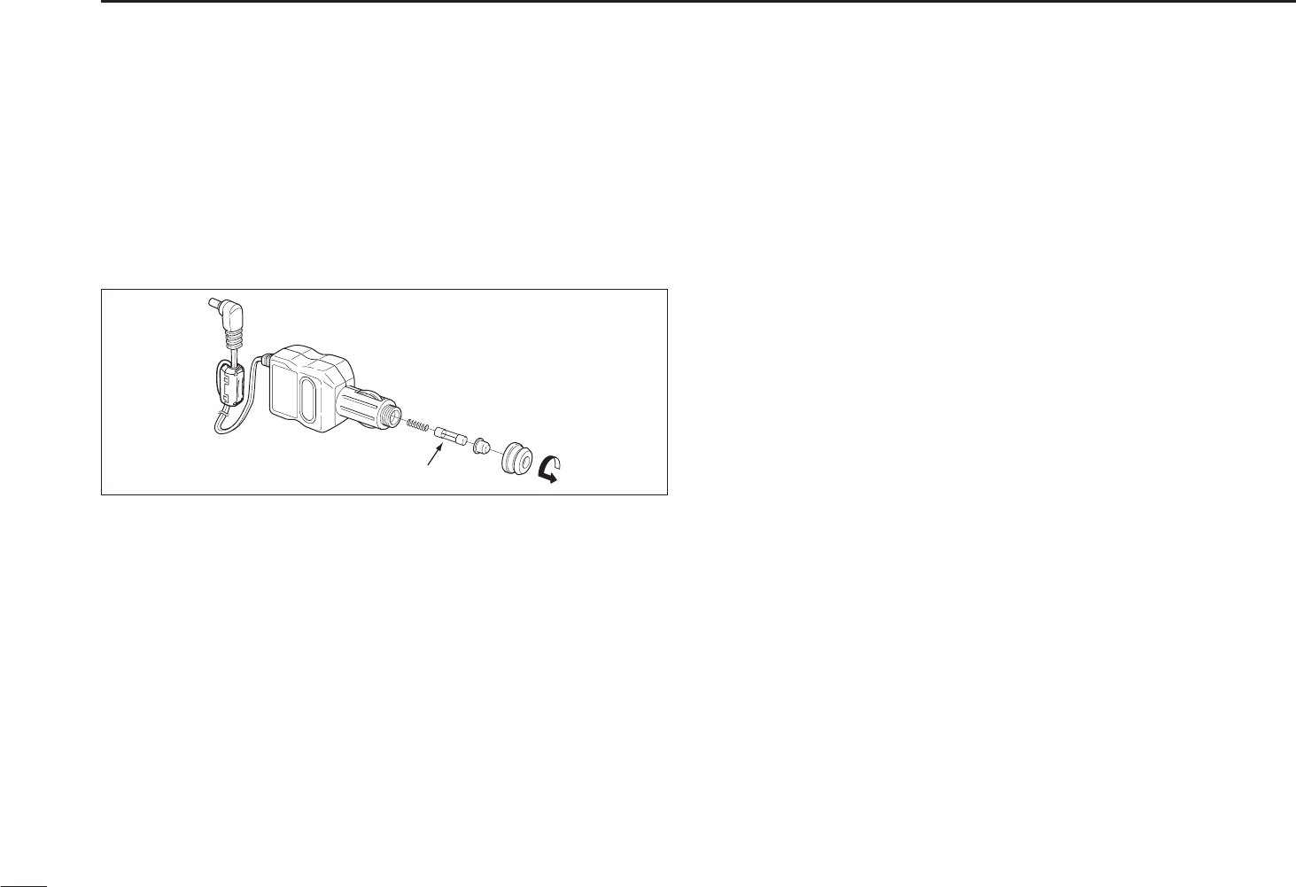
69
12 MAINTENANCE
N CP-18A/E fuse replacement
If the fuse blows, or the receiver stops functioning while
operating with the optional CP-18A/E, find the source of the
problem if possible, solve it and only then replace the dam-
aged fuse with a new rated one (FGB 5 A) as shown below.
Fuse 5 A

70
13
SPECIFICATIONS
12
13
D GENERAL
• Frequency coverage : (Unit: MHz)
USA 0.100–823.995, 851.000–866.995,
896.000–1309.995
France 0.100–29.995, 50.200–51.200,
87.500–107.995, 144.000–146.000,
430.000–440.000, 1240.000–1300.000
Other than above 0.100–1309.995 MHz
• Number of memory channels : 1350 (incl. 50 scan edges and 200 auto
write channels)
• Frequency resolution : 5, 6.25, 8.33,* 9*, 10, 12.5, 15, 20, 25,
30, 50, 100, 125, 200 kHz
*selectable depending on the operating frequency band.
• Receive modes : FM, WFM, AM
• Operating temperature range : –10°C to +60°C; +14˚F to +140˚F
• Reference frequency stability : ±1.0 ppm (+25°C)
• Power supply requirement : 2 AA (R6) alkaline cells
2 AA (R6) Ni-MH cells
4.5 to 6.3 V DC
(with AC adapter or CP-18A/E)
• Current drain (backlight OFF at 3.0 V DC):
rated audio 130 mA typical
receive stanby 65 mA typical
power save (1:4) 30 mA typical
charging 140 mA typical
• Antenna connector : SMA (50 ȍ)
• Dimensions : 58(W) u 86(H) u 29.8(D) mm
(projections not included) 29⁄32(W)u33⁄8(H)u13⁄16(D) in
• Weight (approximately) : 200 g; 7.1 oz
(with supplied antenna and batteries)
• Ext. speaker connector : 3-conductor 3.5 (d) mm (1⁄8s)/8 ȍ
D RECEIVER
• Receive system : Triple-conversion superheterodyne
• Intermediate frequencies : 1st : 266.7 MHz,
2nd : 19.65 MHz (FM/AM),
19.95 MHz (WFM)
3rd : 450 kHz (FM/AM),
750 kHz (WFM)
• Sensitivity (except spurious points): when connecting EXT-ANT
FM (1 kHz/3.5 kHz Dev.; 12 dB SINAD)
1.625–4.995 MHz 0.32 μV typical
5.000–29.995 MHz 0.25 μV typical
30.000–117.995 MHz 0.18 μV typical
118.000–246.995 MHz 0.18 μV typical
247.000–469.995 MHz 0.18 μV typical
470.000–832.995 MHz 0.32 μV typical
833.000–1029.995 MHz 0.28 μV typical
1030.000–1309.995 MHz 0.35 μV typical
WFM (1 kHz/52.5 kHz Dev.; 12 dB SINAD)
76.000–108.000 MHz 1.1 μV typical
175.000–221.995 MHz 1.1 μV typical
470.000–770.000 MHz 1.8 μV typical
AM (1 kHz/30% MOD.; 10 dB S/N)
0.495–4.995 MHz 1.3 μV typical
5.000–29.995 MHz 0.89 μV typical
118.000–136.000 MHz 0.63 μV typical
222.000–246.995 MHz 0.63 μV typical
247.000–329.995 MHz 0.79 μV typical
• Selectivity :
AM/FM More than 12 kHz/–9 dB
Less than 30 kHz/–60 dB
WFM More than 150 kHz/–6 dB
• Audio output power : (at 10% distortion/3.0 V DC)
Internal speaker More than 150 mW with a 16 : load
External speaker 80 mW typical with an 8 : load
All stated specifications are subject to change without notice or obligation.
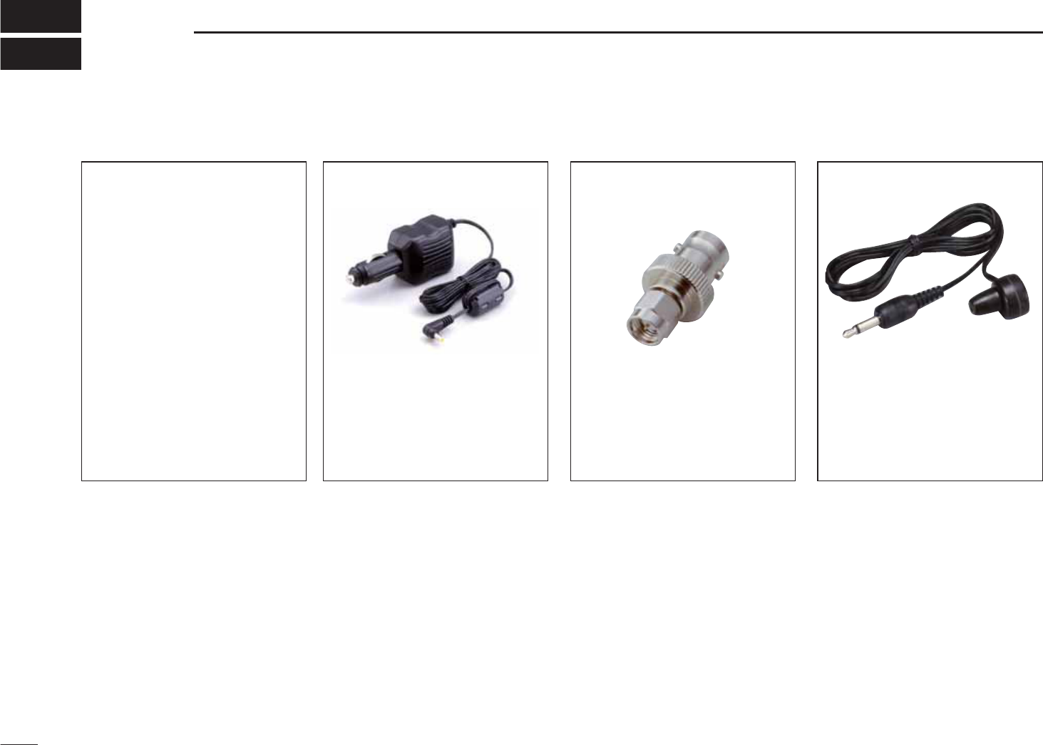
71
OPTIONS
14
NOptions
BC-196SA/SD/153SC AC ADAPTER
Regularly charges the installed
batteries.
BC-196SA/SD:
4.5 V DC/400 mA output
BC-153SC:
6.0 V DC/1 A output
CP-18A/E CIGARETTE LIGHTER
CABLE WITH DC-DC CONVERTER
Allows you to operate the
receiver through a 12 V ciga-
rette lighter socket, and also
charges the installed recharge-
able batteries regularly. A
DC-DC converter is built-in.
AD-92SMA ANTENNA
CONNECTOR ADAPTER
Allows you to connect an exter-
nal antenna with a BNC con-
nector.
SP-13 EARPHONE
Provides clear audio in noisy
environments.
BC-194 CHARGE ADAPTER
Allows you to charge the receiver
on the desktop. Requires AC
adapter or cigarette lighter cable.
LC-146A CARRYING CASE
Helps protect the receiver from
scratches, etc.
OPC-474 CLONING CABLE
For connection between receiv-
ers for data cloning.
OPC-478/OPC-478UC
CLONING CABLE
Used for data cloning between
receiver and PC with CS-R6
(cloning software).
CS-R6 CLONING SOFTWARE
Provides quick and easy pro-
gramming of such settings as
memory channels and Set mode
contents via your PC’s RS-232C
terminal (using OPC-478), or
USB port (OPC-478UC). Either
OPC-478 or OPC-478UC is
required.
CT-17 CI-V LEVEL CONVERTER
For receiver remote control using
a PC.
HP-4 HEAD PHONE
Provides clear audio in noisy
environments.
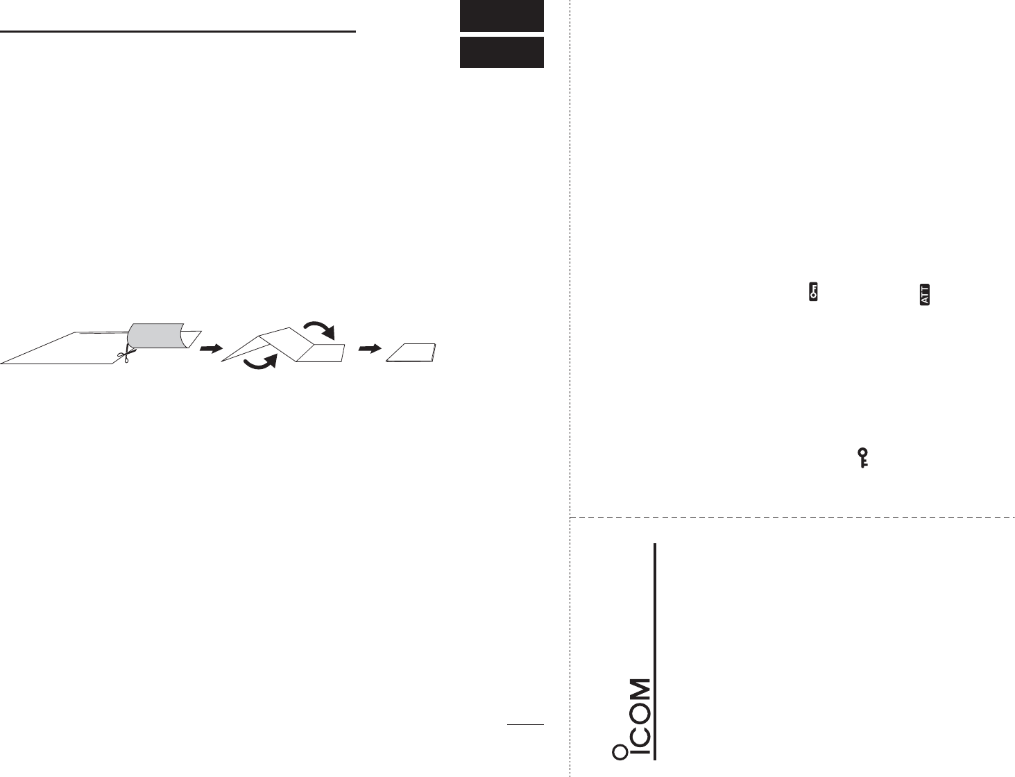
q
w
iR6
VFO and memory mode selection
POCKET GUIDE
Push [V/M] to toggle between the
VFO and the memory mode.
Receive mode selection
Push [MODE] repeatedly to
select the desired mode
Audio level setting
Push [Y] to increase, push [Z]
to decrease the audio level.
Squelch level setting
Hold down [SQL], rotate [DIAL]
to set the squelch level.
Frequency band selection
Push [BAND] repeatedly, or hold
down [BAND], rotate [DIAL] to
select the desired frequency band.
Tuning step selection
Push [TS], then rotate [DIAL] to
select the desired tuning step.
• Push [TS] again to return to the
previous screen.
Key lock function
Hold down [FUNC], push [ ]
(BAND) for 1 sec. to toggle the
key lock function ON or OFF.
• “ ” appears when the lock function
is in use.
Frequency setting
Push [V/M] to select the VFO
mode.
Rotate [DIAL] to set the desired
operating frequency.
q
w
Memory channel selection
Push [V/M] to select the
memory mode.
Rotate [DIAL] to set a desired
memory channel.
• Hold down [FUNC], rotate [DIAL]
changes memory channel in 10
channel steps.
q
w
e
Memory bank channel selection
Push [V/M] to select the
memory mode.
Push [BAND] repeatedly, or
while holding down [BAND],
rotate [DIAL] selects a desired
bank.
Rotate [DIAL] to select the
desired bank channel.
Attenuator function
Hold down [FUNC], push [ ]
(SQL) to toggle the attenuator
ON or OFF.
• “ATT” appears when the attenua-
tor function is in use.
72
15
POCKET GUIDE
Important operating instructions are summed up on this and the following
page for your simple reference.
By cutting along the line and folding on the dotted line, it will become a
card sized operating guide which can easily be carried in a card case or
wallet, etc.
q Cut w Fold e Complete
<CUT HERE>
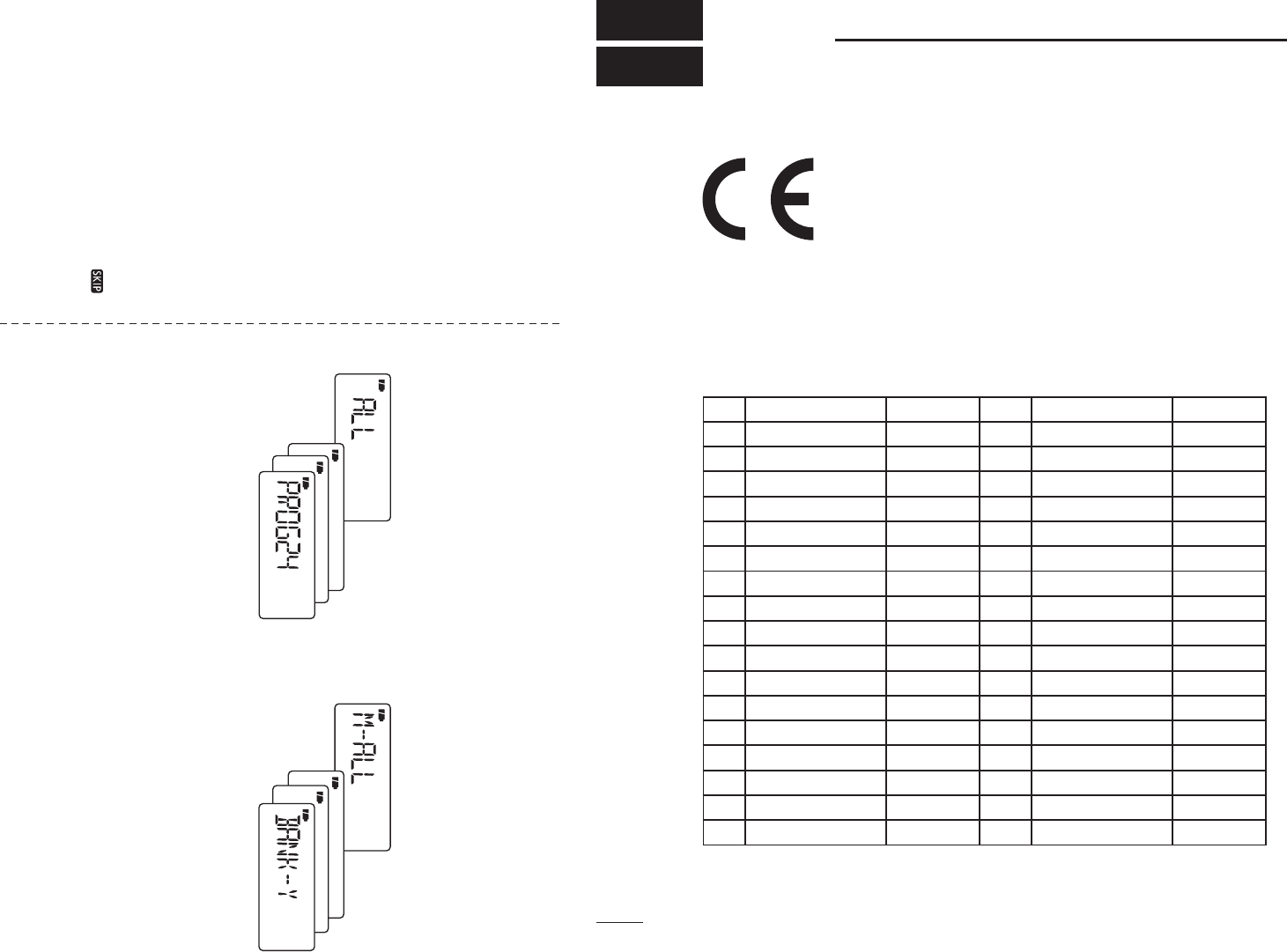
q
w
e
r
Memory channel programming
Set the desired frequency and
other functions in the VFO mode.
Push and hold [S.MW](V/M) for
1 sec. to enter the select
memory write mode.
• 1 short and 1 long beeps sound.
Rotate [DIAL] to select a desired
memory channel.
Push and hold [S.MW](V/M) for
1 sec. to program the contents
into the selected channel.
• 3 beeps sound.
q
w
e
Scan skip setting
Push [V/M] to select the
memory mode.
Rotate [DIAL] to select a desired
memory channel.
Hold down [FUNC], push [ ]
(V/M) to set the skip setting
(skip channel or skip
frequency) ON or OFF.
q
w
VFO scans
Push [V/M] to select the VFO
mode.
Push and hold [SCAN] (MODE)
for 1 sec.
• A scan type appears.
e
r
t
Rotate [DIAL] to select the
desired scan type.
Push [SCAN] (MODE) to start
the scan.
• Rotate [DIAL] to change the scanning
direction.
• During scan, push [V/M] to start the
auto memory write scan.
Push [SCAN](MODE) again to
stop the scan.
q
w
Memory scans
Push [V/M] to select the
memory mode.
Push and hold [SCAN](MODE)
for 1 sec.
• A scan type appears.
e
r
t
Rotate [DIAL] to select the
desired scan type.
Push [SCAN] (MODE) to start
the scan.
• Rotate [DIAL] to change the scanning
direction.
Push [SCAN](MODE) again to
stop scan.
CE Versions of the IC-R6 which display the ‘CE’
symbol on the serial number label, comply with
the essential requirements of the European
Radio and Telecommunication Terminal Direc-
tive 1999/5/EC
73
16 CE
• List of Country codes (ISO 3166-1)
Country Codes Country Codes
1 Austria AT 18 Liechtenstein LI
2 Belgium BE 19 Lithuania LT
3 Bulgaria BG 20 Luxembourg LU
4 Croatia HR 21 Malta MT
5Czech Republic CZ 22 Netherlands NL
6 Cyprus CY 23 Norway NO
7 Denmark DK 24 Poland PL
8 Estonia EE 25 Portugal PT
9 Finland FI 26 Romania RO
10 France FR 27 Slovakia SK
11 Germany DE 28 Slovenia SI
12 Greece GR 29 Spain ES
13 Hungary HU 30 Sweden SE
14 Iceland IS 31 Switzerland CH
15 Ireland IE 32 Turkey TR
16 Italy IT 33 United Kingdom GB
17 Latvia LV

74
16
CE
1
2
3
4
5
6
7
8
9
10
11
12
13
14
15
16
DECLARATION
OF CONFORMITY
We Icom Inc. Japan
1-1-32, Kamiminami, Hirano-ku
Osaka 547-0003, Japan
Kind of equipment:
Type-designation:
Signature
Authorized representative name
Place and date of issue
Version (where applicable):
This compliance is based on conformity with the following harmonised
standards, specifications or documents:
Bad Soden
Y. Furukawa
General Manager
Icom (Europe) GmbH
Communication Equipment
Auf der Krautweide 24,
65812 Bad Soden am Taunus,
Germany
i)
ii)
iii)
iv)
Declare on our sole responsibility that this equipment complies with the
essential requirements of the Radio and Telecommunications Terminal
Equipment Directive, 1999/5/EC, and that any applicable Essential Test
Suite measurements have been performed.
EN 301 489-1 v1.6.1 (September 2005)
EN 301 489-15 v1.2.1 (August 2002)
EN 301 783-2 v1.1.1 (September 2000)
EN 60950-1 (2001): A11: 2004
COMMUNICATIONS RECEIVER
iC- r6
24th Dec. 2009
1-1-32 Kamiminami, Hirano-ku, Osaka 547-0003, Japan
Printed on recycled paper with soy ink.
A-6810H-1EX
Printed in Japan
©2009 Icom Inc.
#02 Europe
#12 Europe-1
#03 U.K.
#04 Italy
#14 Italy-1
#07 France
#17 France-1
#08 Spain
#18 Spain-1
<Intended Country of Use>
N AT N BE N CY N CZ N DK N EE
N FI N FR N DE N GR N HU N IE
N IT N LV N LT N LU N MT N NL
N PL N PT N SK N SI N ES N SE
N GB N IS N LI N NO N CH N BG
N RO N TR N HR
<Intended Country of Use>
N AT N BE N CY N CZ N DK N EE
N FI N FR N DE N GR N HU N IE
N IT N LV N LT N LU N MT N NL
N PL N PT N SK N SI N ES N SE
N GB N IS N LI N NO N CH N BG
N
RO N TR N HR
<Intended Country of Use>
N AT N BE N CY N CZ N DK N EE
N FI N FR N DE N GR N HU N IE
N IT N LV N LT N LU N MT N NL
N PL N PT N SK N SI N ES N SE
N GB N IS N LI N NO N CH N BG
N
RO N TR N HR
<Intended Country of Use>
N AT N BE N CY N CZ N DK N EE
N FI N FR N DE N GR N HU N IE
N IT N LV N LT N LU N MT N NL
N PL N PT N SK N SI N ES N SE
N GB N IS N LI N NO N CH N BG
N
RO N TR N HR
<Intended Country of Use>
N AT N BE N CY N CZ N DK N EE
N FI N FR N DE N GR N HU N IE
N IT N LV N LT N LU N MT N NL
N PL N PT N SK N SI N ES N SE
N GB N IS N LI N NO N CH N BG
N
RO N TR N HR