ICOM orporated 325300 VHF/UHF Dual Band FM Transceiver User Manual
ICOM Incorporated VHF/UHF Dual Band FM Transceiver
UserManual.wiki
>
ICOM orporated
>
325300 User Manual
Users Manual
Navigation menu
Upload a User Manual
Namespaces
Wiki Guide
HTML
PDF
Info
Views
User Manual
Discussion / Help
Navigation
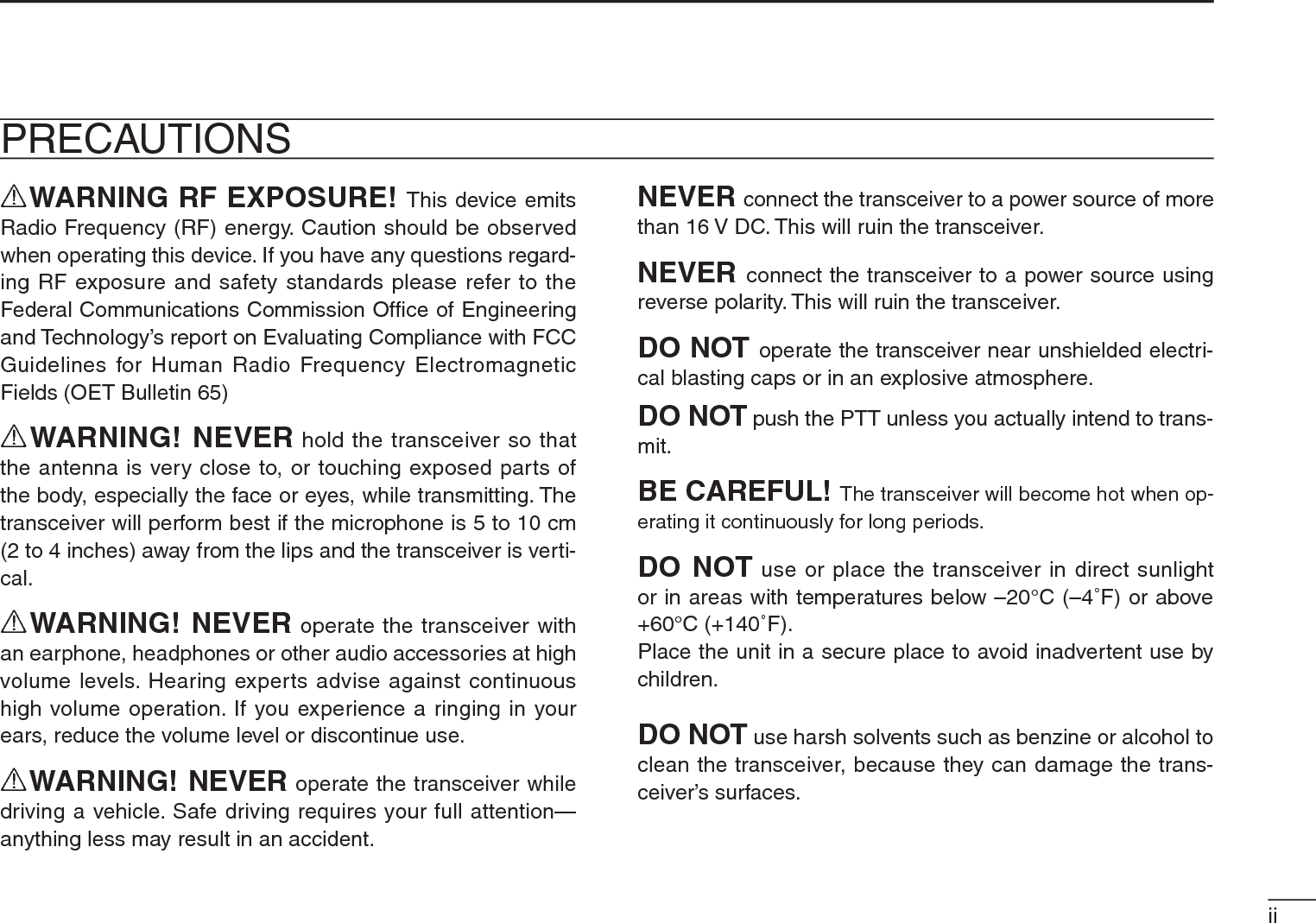
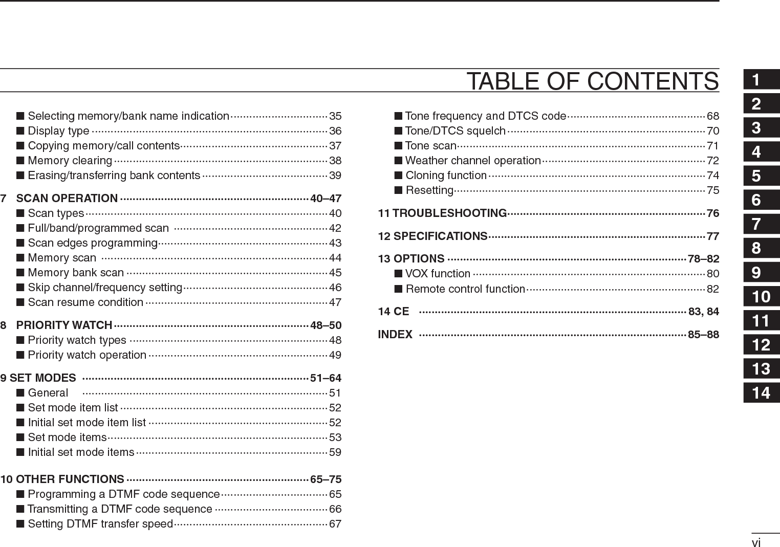
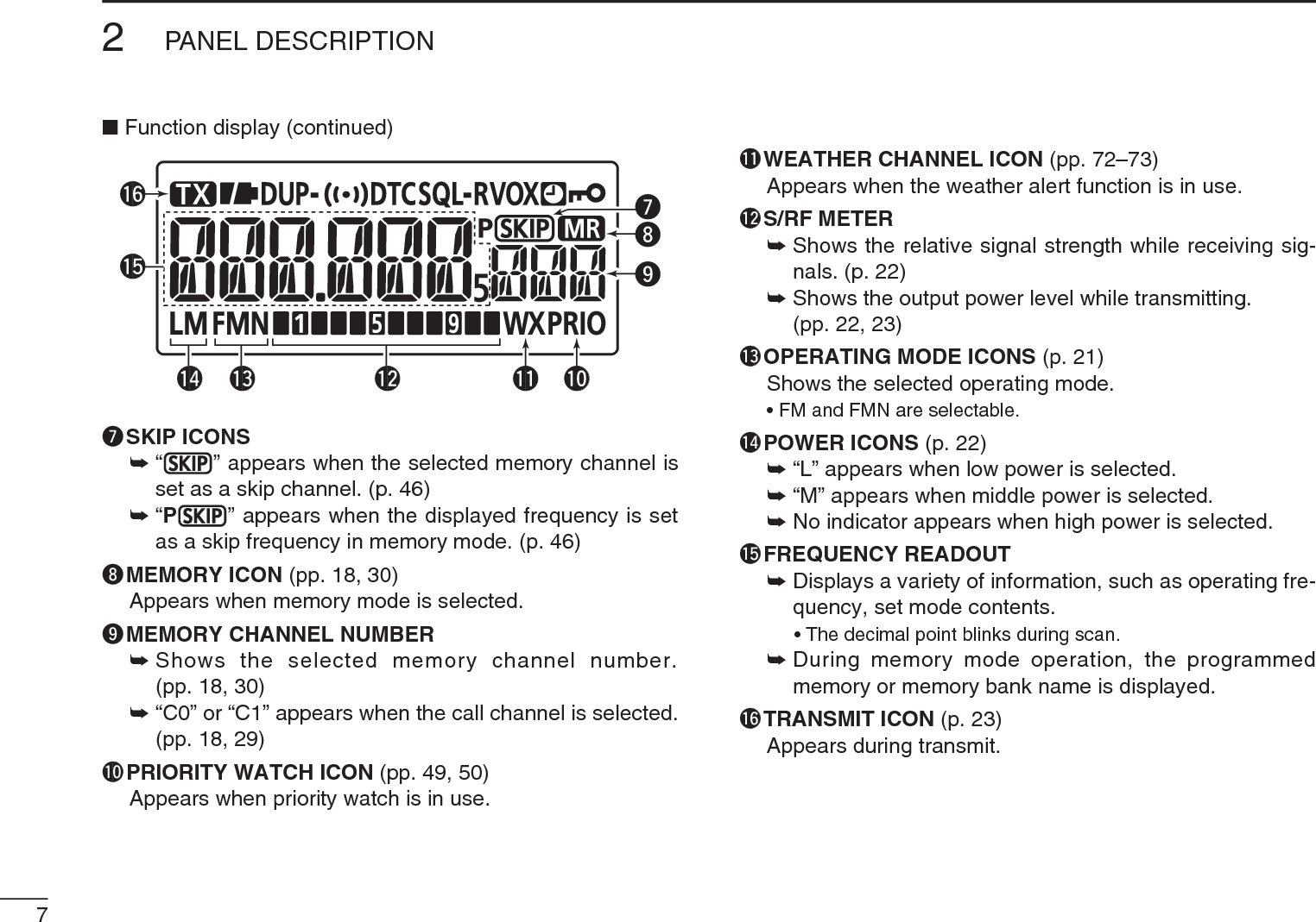
![3PANEL DESCRIPTION2N Front, top and side panelsSpeakerANTENNACONNECTOREXTERNALDC IN JACKVOLUMECONTROLCONTROL DIALEXTERNAL SPEAKER/MICROPHONE JACKSKeypad (pp. 4, 5)Internal microphoneFunction display (pp. 6, 7)PTT SWITCHerywqtqANTENNA CONNECTOR (p. 3)Connects the supplied antenna.• An optional AD-92SMA adapter (p. 79) is available for connect-ing an antenna with a BNC connector.wEXTERNAL SPEAKER/MICROPHONE JACKS [SP/MIC]Connect an optional speaker microphone, cloning cable, or headset, if desired.See page 79 for a list of available options.Be sure to turn power OFF before connecting or dis-connecting optional equipment to/from the [SP/MIC] jack.eCONTROL DIAL [DIAL]± Rotate to tune the operating frequency. (p. 19)±During memory mode, rotate to select the memory channel. (pp. 18, 30)±While scanning, changes the scanning direction. (pp. 42, 44, 45)±While continuing to push [MONI](BAND), sets the squelch level. (p. 17)±After pushing [BAND] during memory mode operation, selects the programmed bank. (p. 33)±During set mode operation, rotate to select the set items. (p. 51)](https://usermanual.wiki/ICOM-orporated/325300/User-Guide-1227495-Page-10.png)
![42PANEL DESCRIPTION12345678910111213141516171819rVOLUME CONTROL [VOL]±Adjust audio volume level. (p. 16)±During set mode operation, rotate to select the options. (p. 51)tPTT SWITCH [PTT]±Push and hold to transmit, release to receive. (p. 23)For IC-T70E only±Push briefly, then push and hold to transmit a 1750 Hz tone burst. (p. 28)yEXTERNAL DC IN JACK [DC IN]±Connects the supplied wall charger, BC-167S, to charge the attached battery pack, BP-264. (p. 12)• The transceiver can charge only the Ni-MH battery pack, BP-264. Charging the Li-Ion battery pack, BP-265 requires the rapid charger, BC-193.±Connect an external DC power supply through the op-tional CP-12L, CP-19R or OPC-254L for external DC operation. (p. 15)D Keypad±Push to input numeral for frequency input, memory chan-nel selection.±Push to send the DTMF code. (pp. 66, 67) • [0]–[9] send “0”–“9,” [A](SET) sends “A,” [B](BAND) sends “B,” [C](H/M/L) sends “C,” [D](V/M/C) sends “D,” [1](DUP) sends “1(E)” and [#](T.SCAN) sends “# (F).”POWER KEY [ ]±Push and hold for 1 sec. to turn the transceiver power ON or OFF. (p. 16)VFO/MEMORY/CALL • SELECT MEMORY WRITE KEY[V/M/C] • [S.MW](V/M/C)±Push to select the VFO mode, memory mode, call channel mode or weather channel mode*. (pp. 18, 29, 30, 72) *Only for the U.S.A. version transceiver.±Push and hold for 1 sec. to enter select memory write mode. (p. 31)](https://usermanual.wiki/ICOM-orporated/325300/User-Guide-1227495-Page-11.png)
![52PANEL DESCRIPTIONDKeypad (continued)BAND • MONITOR KEY [BAND] • [MONI](BAND)±During VFO mode operation, push to select an operating frequency band. (p. 19)±Push and hold to open the squelch temporarily and monitor the operating frequency. (p. 17)±While continuing to push this key, rotate [DIAL] to adjust the squelch level. (p. 17)±During memory mode operation, push to enter the memory bank group selection. (p. 33)OUTPUT POWER • SCAN KEY [H/M/L] • [SCAN](H/M/L)±Push to select the output power. (p. 22)• Selects the transmit output power from high, mid or low.±Push and hold for 1 sec. to enter the scan type selection mode. (pp. 42, 44, 45)• Push again to start the scan.SET • LOCK KEY [SET] • [ ](SET)±Push to enter the Set mode. (p. 51)±Push and hold for 1 sec. to toggle the lock func-tion ON or OFF. (p. 21)±During select memory write mode, push to select the items. (pp. 32, 34, 38, 39)TONE SCAN [T.SCAN](#)±Push and hold for 1 sec. to start tone scan func-tion. (p. 71)TONE/TONE SQUELCH KEY [TONE](0)±Push and hold for 1 sec. to select repeater tone, tone squelch, tone squelch reverse, DTCS squelch, DTCS squelch reverse and no tone op-eration in sequence. (p. 70)• Pocket beep function is available for tone squelch and DTCS squelch. (p. 70)DUPLEX KEY [DUP](1)±Push and hold for 1 sec. to select minus duplex, plus duplex or simplex operation. (p. 26)• “DUP–” (minus duplex), “DUP” (plus duplex) and no indication (simplex) appear in order.](https://usermanual.wiki/ICOM-orporated/325300/User-Guide-1227495-Page-12.png)
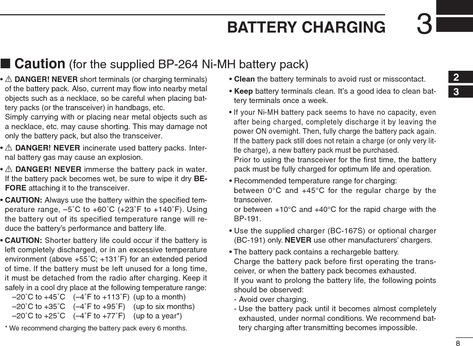
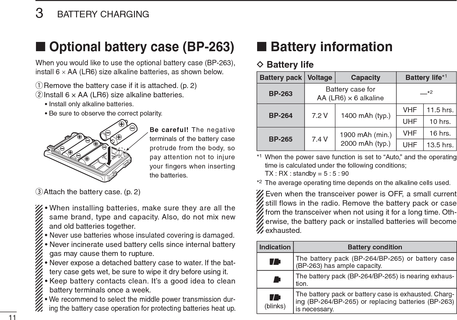
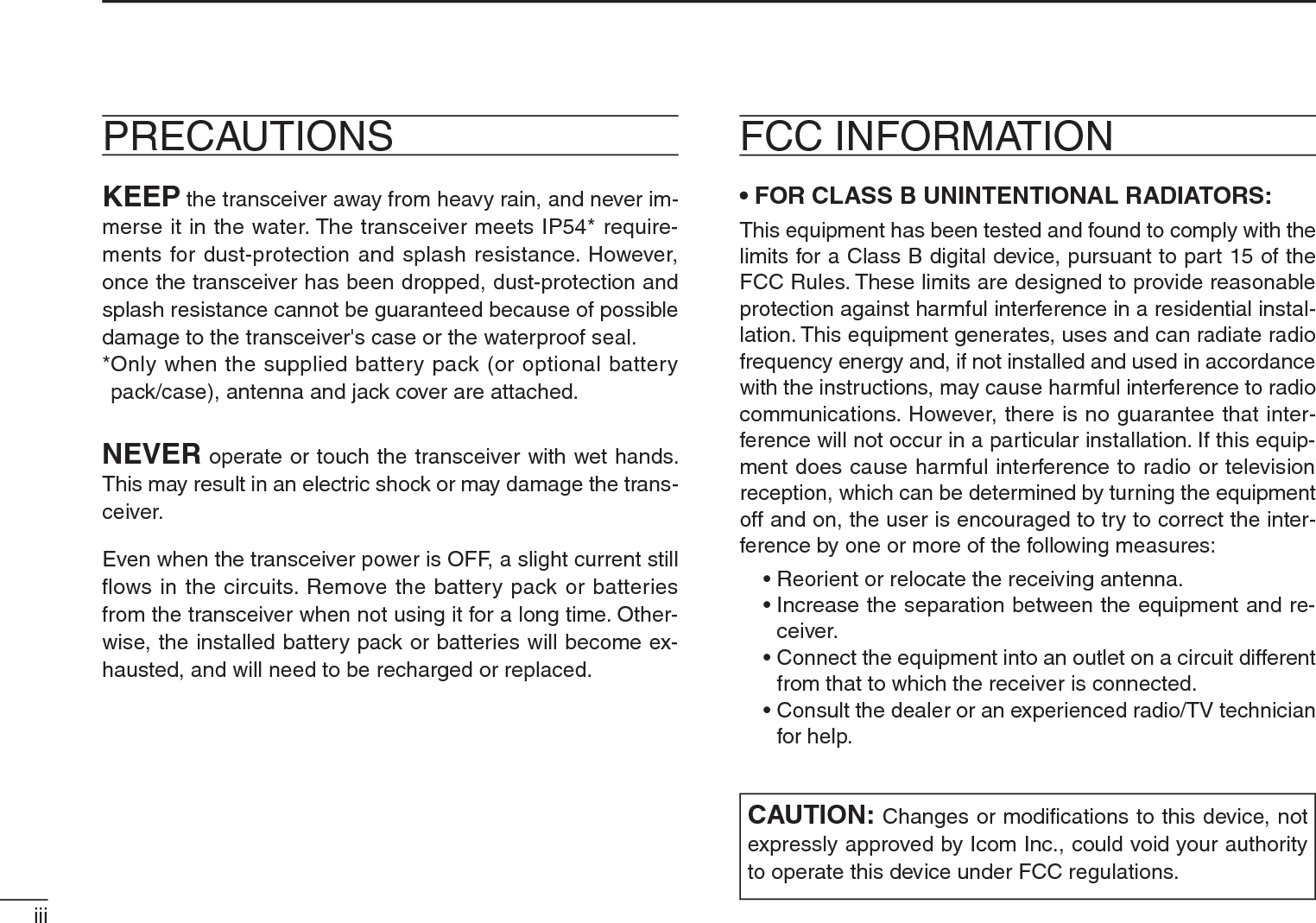
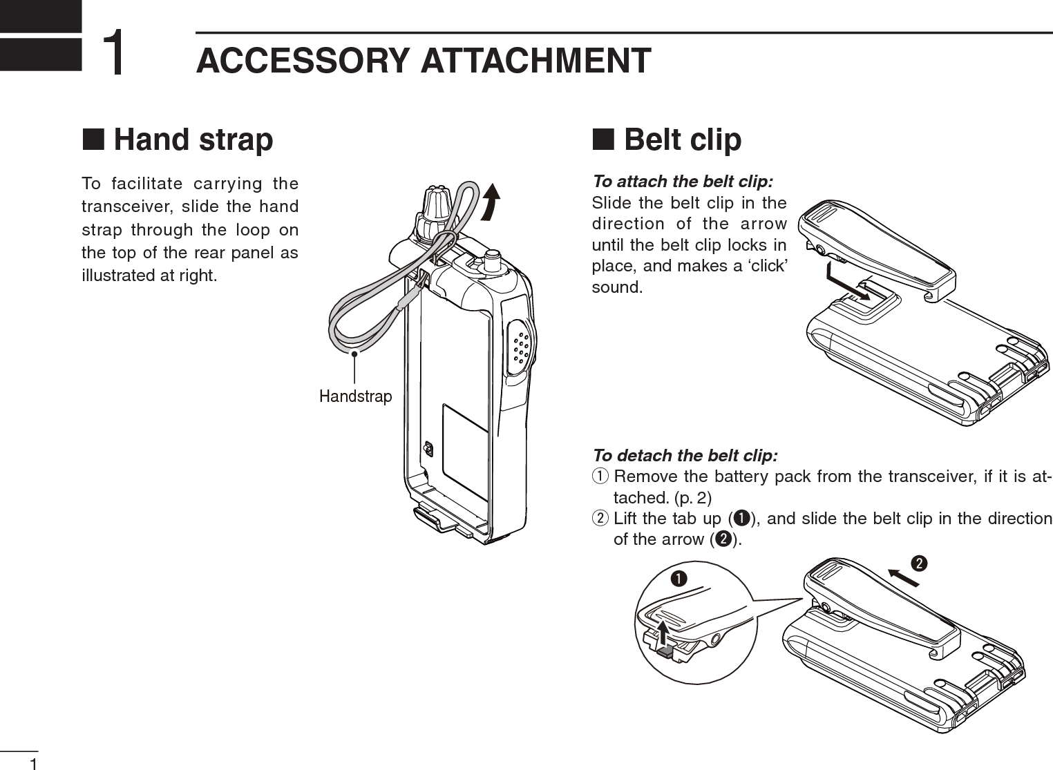
![123BATTERY CHARGING3N Regular chargingPrior to using the transceiver for the first time, the battery pack must be fully charged for optimum life and operation.DBattery iconsThe icons show “ ,” “ ” and “ (disappers)” in se-quence and “CHARGE” appears while charging (when the transceiver’s power is OFF). The icons and “CHARGE” dis-appear when the battery pack is completely charged.DCharging note• Be sure to turn the transceiver power OFF.Otherwise the battery pack will not be charged completely or will take much longer to charge.• The transceiver can charge only the BP-264 battery pack. Other types of rechargeable battery, Ni-Cd or Li-Ion batter-ies cannot be charged.• External DC power operation becomes possible when using an optional CP-12L, CP-19R or OPC-254L. The attached battery pack is also charged simultaneously, except during transmit (see p. 15 for more details).• The external DC power supply voltage must be between 10–16 V to charge the battery pack and for operation when using an optional OPC-254L. (We recommend 11 V DC for operation.)• If the battery icons (“ ” and “ ”) disappears only after 1 min. from connecting to the DC power supply, the bat-tery pack may have problem. In this case, contact your Icom dealer/distributor, or purchase a new battery pack.• BC-167S• CP-12L (Optional)• OPC-254L (Optional)to AC outletto cigarette lightersocket (12 V DC)to 11 V DC(power supply)White: +Black: _Transceiverto[DC IN]Turn power OFF while charging the batterypack.The shape maydiffe depending on the version.• Charging time period:Approx. 8 hoursBP-264• CP-19R (Optional)Be sure to disconnect the AC adapter from the AC outlet after the battery charging is completed, otherwise the trans-ceiver may receive switching noise from the AC adapter de-pending on the operating frequencies and/or antenna used.](https://usermanual.wiki/ICOM-orporated/325300/User-Guide-1227495-Page-19.png)
![133BATTERY CHARGINGThe optional BC-191 provides rapid charging of the Ni-MH battery pack BP-264.DCharging note• Be sure to turn the transceiver power OFF.• The desktop charger, BC-191, can charge only the BP-264 battery pack. Other types of rechargeable battery, Ni-Cd or Li-Ion batteries cannot be charged.•NEVER install the transceiver with battery pack to the BC-191 when the transceiver is connected to the DC power supply. This may cause the BC-191’s manufunction and the charging indicator of the BC-191 lights red. In this case, dis-connect the AC adapter from the BC-191, and then recon-nect the AC adapter to the BC-191.• The optional CP-23L and OPC-515L can be used instead of the supplied AC adapter. Connect one of these to the [DC 12-16V] jack in this case.• Charging period: approx. 2 hours (with BP-264)TransceiverBattery packCharge indicator• Lights orange : While charging• Lights green : Charging is completed.• Blinks red : Charging error occurs.Screws*(Self tapping screw:M3.5 × at least 30 mm)*Purchase separately.Using screws isrecommended tosecure the charger.About OPC-515LWhite line: Black line:CAUTION: NEVER connect the OPC-515L to a power sourceusing reverse polarity. This willruin the battery charger.+–Optional OPC-515L(for DC powersource) or CP-23L(for 12 V cigarettelighter socket) canbe used instead ofthe AC adapter.BC-123S(suppliedwith BC-191)Turn power OFFN Rapid charging with the BC-191](https://usermanual.wiki/ICOM-orporated/325300/User-Guide-1227495-Page-20.png)
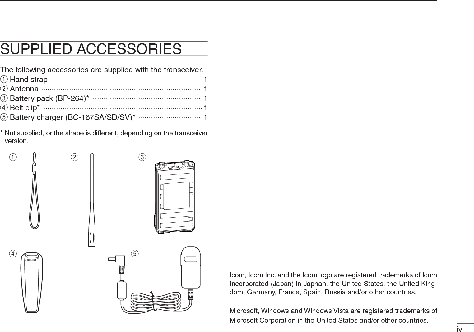
![143BATTERY CHARGING3The optional BC-193 provides rapid charging of the Li-Ion-battery pack BP-265.DCharging note• Be sure to turn the transceiver power OFF.• The desktop charger, BC-193, can charge only the BP-265 battery pack. Other types of rechargeable battery, Ni-Cd or Ni-MH batteries cannot be charged.•NEVER install the transceiver with battery pack to the BC-193 when the transceiver is connected to the DC power supply. This may cause the BC-193’s manufunction and the charging indicator of the BC-193 lights red. In this case, dis-connect the AC adapter from the BC-193, and then recon-nect the AC adapter to the BC-193.• The optional CP-23L and OPC-515L can be used instead of the supplied AC adapter. Connect one of these to the [DC 12-16V] jack in this case.• Charging period: approx. 2.5 hours (with BP-265)TransceiverTurn power OFFBattery packBC-123S(suppliedwith BC-193)The optional OPC-515L (for DC powersource) or CP-23L(for 12 V cigarettelighter socket) canbe used instead ofthe AC adapter.Charge indicator• Lights orange : While charging• Lights green : Charging is completed.• Blinks red : Charging error occurs.Screws*(Self tapping screw:M3.5 × at least 30 mm)*Purchase separately.Using screws isrecommended tosecure the charger.About OPC-515LWhite line: Black line:CAUTION: NEVER connect theOPC-515L to a power sourceusing reverse polarity. This willruin the battery charger.+–IMPORTANT!Ensure the tabs onthe battery pack arecorrectly aligned withthe guide rails insidethe charger adapter.Guide railTabsN Rapid charging with the BC-193](https://usermanual.wiki/ICOM-orporated/325300/User-Guide-1227495-Page-21.png)
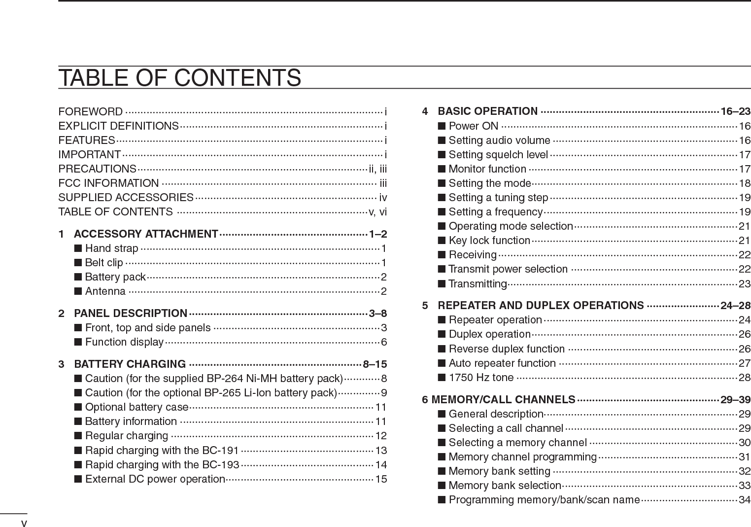
![153BATTERY CHARGINGN External DC power operationAn optional cigarette lighter cable (CP-12L or CP-19R; for 12 V cigarette lighter socket) or external DC power cable (OPC-254L) can be used for external power operation. (We recommend the CP-19R when you want to connect a 12 V cigarette lighter socket.)D Operating note• Power supply voltage must be between 10.0–16.0 V DC. (We recommend 11.0 V DC.) NEVER CONNECT OVER 16 V DC directly into the [DC IN] jack of the transceiver.•BE SURE to use CP-12L, CP-19R or OPC-254L when connecting a regulated 12 V DC power supply.Use an external DC-DC converter to connect the transceiver through optional CP-12L, CP-19R or OPC-254L to a 24 VDC power source.• The voltage of the external power supply must be within 10–16 V DC when using either CP-12L, CP-19R or OPC-254L, otherwise, use the battery pack/battery case.• Disconnect the power cable from the transceiver when not using it. Otherwise, the vehicle battery will become ex-hausted.• The power save function is deactivated automatically dur-ing external DC power operation.TransceiverBP-264• CP-12L (Optional)• CP-19R (Optional)• OPC-254L (Optional)to cigarette lightersocket (12 V DC)to 11 V DC(power supply)White: +Black: _to[DC IN]NOTE: Up to 5 W (approx.) of maximum output power is available when using external DC power. However, when the supplied voltage exceeds 14 V, the built-in protection circuit activates to reduce the transmit output power to 2.5 W (approx.).](https://usermanual.wiki/ICOM-orporated/325300/User-Guide-1227495-Page-22.png)
![164BASIC OPERATION12345678910111213141516171819N Power ON± Push and hold [ ] for 1 sec. to turn power ON.• Push and hold [ ] for 1 sec. to turn power OFF.The voltage indication is skipped in the Initial set mode (p. 61).N Setting audio volume± Rotate [VOL]to adjust the audio level. • If squelch is closed, push and hold [MONI](BAND) while setting the audio level.• The display shows the volume level while setting.[VOL]Minimum setting (no audio)Maximum settingVolume levelThe beep level is adjustable in the Initial set mode (p. 60).](https://usermanual.wiki/ICOM-orporated/325300/User-Guide-1227495-Page-23.png)
, rotate [DIAL] to select the squelch level.• “LEVEL1” is loose squelch (for weak signals) and “LEVEL9” is tight squelch (for strong signals).• “Auto” indicates automatic level adjustment by a noise pulse counting system.• “OPEn” indicates continuously open setting.[DIAL]Maximum levelAutomatic squelchN Monitor functionThis function is used to listen to weak signals without disturb-ing the squelch setting or to open the squelch manually even when mute functions such as the tone squelch are in use.±Push and hold [MONI](BAND) to monitor the operating frequency.• The 1st and 2nd segments of the S-meter blink.Two segments blinkThe [MONI] key can be set to ‘sticky’ operation in the Initial set mode. See page 63 for details.](https://usermanual.wiki/ICOM-orporated/325300/User-Guide-1227495-Page-24.png)
![184BASIC OPERATION12345678910111213141516171819N Setting the modeq Push [V/M/C] repeatedly to select the VFO mode, memory mode, call channel mode or weather channel mode*, in sequence*Only for the U.S.A. version transceiver.w Rotate [DIAL] to change the fre-quency or select a desired channel.D VFO modeThe VFO mode is used to set the desired frequency.• VFO mode displayWhat is VFO?VFO is an abbreviation of Variable Frequency Oscillator. Fre-quencies for both transmitting and receiving are generated and controlled by the VFO.D Memory modeMemory mode is used for opera-tion on memory channels which store programmed frequencies.•“ ” appears when memory mode is selected.• Only programmed memory chan-nels can be selected.• Enter the memory channel directly to select the desired memory channel. (p. 30)D Call channel modeThe Call channel is used for quick recall of most often-used frequency.• “C0” or “C1” appears instead of the memory channel number when the Call channel mode is selected.D Weather channel mode*There are 10 weather channels for monitoring weather broad-casts from NOAA (National Oceanic and Atmospheric Ad-ministration).*Only for the U.S.A. version transceiver.[DIAL]• Memory mode displayAppears• Call channel display• Weather channel display](https://usermanual.wiki/ICOM-orporated/325300/User-Guide-1227495-Page-25.png)
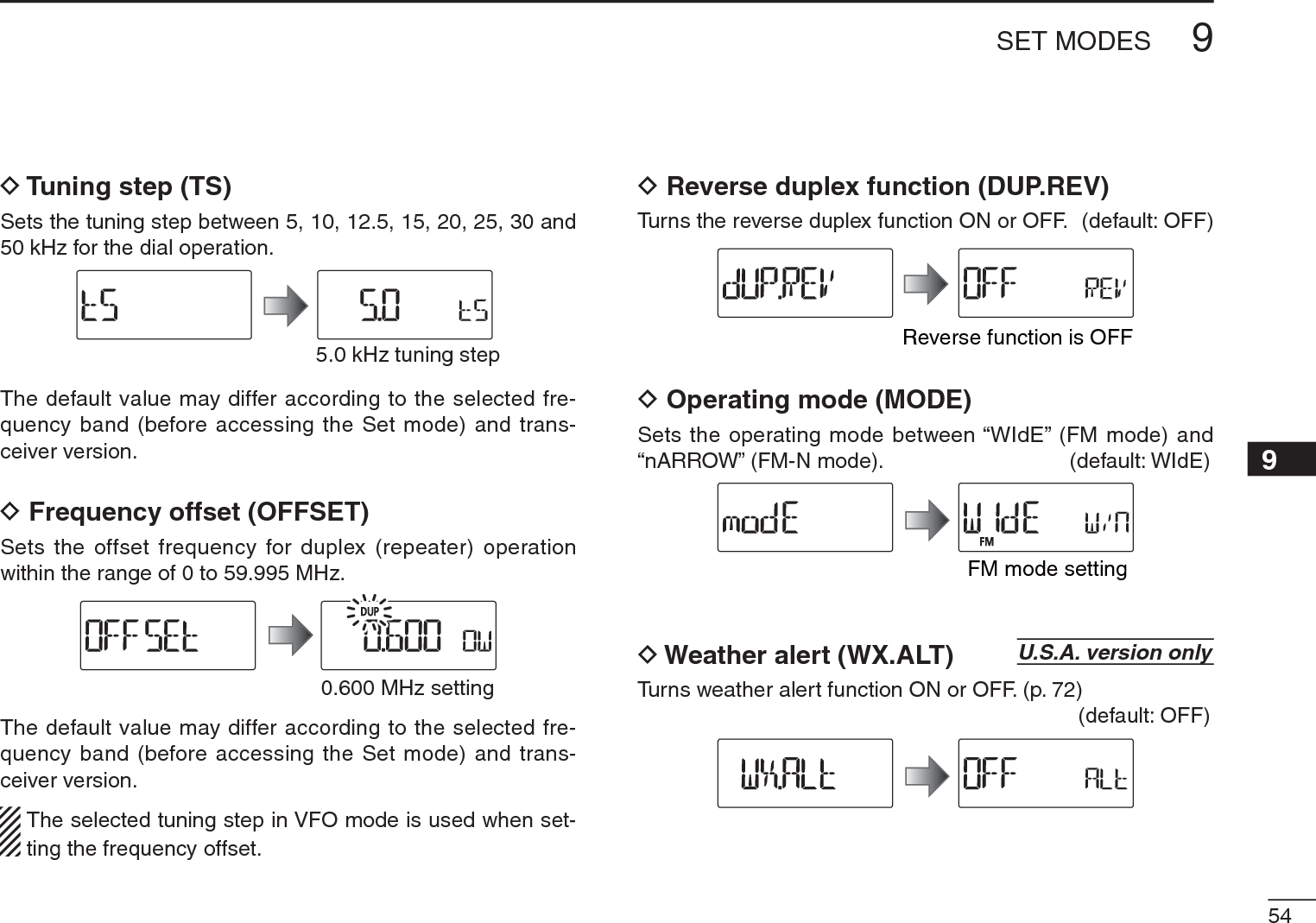
![194BASIC OPERATIONN Setting a tuning stepThe tuning step can be selected for both band. The following tuning steps are available for the IC-T70A/T70E.• 5.0 kHz • 10.0 kHz • 12.5 kHz • 15.0 kHz• 20.0 kHz • 25.0 kHz • 30.0 kHz • 50.0 kHz• 100.0 kHz • 125.0 kHz • 200.0 kHzD Tuning step selectionq In the VFO mode, push [BAND] to select the desired fre-quency band.• If the VFO mode is not selected, such as a memory channel/call channel mode or the weather channel mode, push [V/M/C] to select the VFO mode first, then push [BAND] to select the de-sired band.w Push [SET] to enter the Set mode.e Rotate [DIAL] to select the tuning step set item, then ro-tate [VOL] to select the desired tuning step.rPush [V/M/C] to return to the VFO mode.[VOL][DIAL]5 kHz tuning stepN Setting a frequencyD Using the dialq Push [V/M/C] to select the VFO mode, if any other mode is selected.w Push [BAND] to select the desired frequency band.eRotate [DIAL] to select the desired frequency.• The frequency changes according to the preset tuning steps. See the previous content to set the tuning step.[DIAL][DIAL] changes the frequencyaccording to the selectedtuning step.• 144 MHz band• 400 MHz bandPush [BAND]](https://usermanual.wiki/ICOM-orporated/325300/User-Guide-1227495-Page-26.png)
![D Using the keypadThe frequency can be directly set via numeric keys.• If a frequency outside the frequency range is en-tered, the previously displayed frequency is auto-matically recalled after entering last digit.q Push [V/M/C] to select the VFO mode, if any other mode is selected.w Enter the desired frequency via the keypad.204BASIC OPERATION12345678910111213141516171819Depending on the tuning step setting, it may not be possible to input a 1 kHz digit. In this case, enter “0” as 1 kHz digit, then ro-tate [DIAL] to set the desired frequency.• Entering 145.580 MHz• Changing 100 kHz and belowEditing 145.550 MHz to 145.640 MHzPush to cancel numeral key input.](https://usermanual.wiki/ICOM-orporated/325300/User-Guide-1227495-Page-27.png)
![N Operating mode selectionOperating modes are determined by the modulation of the radio signals. The transceiver has two operating modes, FM and FM-N (narrow). The mode selection is stored indepen-dently for each band and memory channel.q Push [V/M/C] to select the VFO mode, if any other mode is selected.w Push [BAND] to select the desired frequency band.e Push [SET] to enter the Set mode.r Rotate [DIAL] to select the operating mode set item, then rotate [VOL] to select “WIDE” (FM) or “nARROW” (FM-nar-row).tPush [V/M/C] to return to the VFO mode.[VOL][DIAL]: Rotate [VOL]FM FMNN Key lock functionTo prevent accidental frequency changes and unnecessary function access, use the lock function. ±Push and hold [](SET) for 1 sec. to turn the lock func-tion ON or OFF.• “ ” appears while the lock function is activated.•[],[ ](SET), [MONI](BAND), [PTT],[VOL] and squelch ad-justment ([MONI](BAND) + [DIAL]) are operable while the lock function is activated.AppearsTo prevent accidental transmission, etc., the transceiver has a PTT lock function. Turns the PTT lock function ON or OFF in the Initial set mode. (p. 62)214BASIC OPERATION](https://usermanual.wiki/ICOM-orporated/325300/User-Guide-1227495-Page-28.png)
![224BASIC OPERATION12345678910111213141516171819N ReceivingMake sure a charged battery pack (BP-264, BP-265) or brand new alkaline batteries (BP-263) are installed (pp. 2, 12–14).qPush and hold [] for 1 sec. to turn power ON.w Rotate [VOL] to set the desired audio level. (p. 16)• The frequency display shows the volume level while setting.eSet the receiving frequency. (p. 20)rSet the squelch level. (p. 17)• While continuing to push [MONI](BAND), rotate [DIAL].• The first click of [DIAL] indicates the current squelch level.• “LEVEL1” is loose squelch (for weak signals) and “LEVEL9” is tight squelch (for strong signals).• “Auto” indicates automatic level adjustment by a noise pulse counting system.• Push and hold [MONI](BAND) to open the squelch manually.t When a signal is received:• Squelch opens and audio is output.• The S/RF meter shows the relative signal strength level.qr Set squelch levele Set frequencyr Push and hold forsetting the squelch(Push and hold to monitor)e Select bandw Set audio levelN Transmit power selectionThe transceiver has three output power levels to suit your op-erating requirements. Low output power during short-range communications may reduce the possibility of interference to other stations and will conserve battery power.± Push [H/M/L] to toggle the transmit output power between High (5W*), Mid (2.5 W*) and Low (0.5 W*). *approx.AppearsLow power transmissionMid. power transmissionHigh power transmission• During transmitting](https://usermanual.wiki/ICOM-orporated/325300/User-Guide-1227495-Page-29.png)
 to listen on the frequency before transmitting.Microphone[PTT]q Set the operating frequency. (p. 20)• Transmission is available on the 144 MHz/400 MHz amateur bands only.• Select output power if desired. See pre-vious page for details.w Push and hold [PTT] to transmit.•“ ” appears.• S/RF meter shows the output power level.e Speak into the microphone using your normal voice level.• DO NOT hold the transceiver too close to your mouth or speak too loudly. This may distort your speech.rRelease [PTT] to return to receive.RWARNING!NEVER continuously transmit for long periods of time. When the transceiver is used for continuous prolonged transmission at high power, the transceiver radiates heat to protect itself from overheating and transceiver’s chassis will become hot. This may cause a burn.DO NOT operate the transceiver in a situation that will ob-struct heat dissipation, especially if the transceiver is oper-ated with an external power supply. Heat dissipation may be affected, and it may cause a burn, warp the casing or damage the transceiver.NOTE: When the transceiver becomes hot from continuous transmission, etc., the transceiver’s heat protection gradu-ally reduces the output power to 2.5 W (Mid), then it stops transmission after that, to protect the transceiver itself until it has cooled down.• “M” (Power icon) blinks during the heat protection reduces the output power.• “Hot” is displayed during the heat protection inhibits the transmis-sion.CAUTION: Transmitting without an antenna will damage the transceiver.](https://usermanual.wiki/ICOM-orporated/325300/User-Guide-1227495-Page-30.png)
![245REPEATER AND DUPLEX OPERATIONS12345678910111213141516171819N Repeater operationWhen using a repeater, the transmit frequency is shifted from the receive frequency by the frequency offset (p. 54). This is called duplex operation. It is convenient to program repeater information into memory channels (p. 29).Station A Station BRepeater145.300 MHz144.700 MHz 144.700 MHz145.300 MHzUplinkDownlink(transmitting freq.)(receiving freq.)q Set the receive frequency (repeater output frequency).w Set the shift direction of the transmit frequency. (DUP– or DUP; see p. 26 for details.)• When the auto repeater function is in use (U.S.A. and Korean versions only), this selection and step e are not necessary. (p. 27)“DUP–”or “DUP” appears[PTT]TAppearse Push and hold [TONE](0) for 1 sec. to activate the subaudible tone encoder, according to repeater re-quirements.• “T” appears. Refer to p. 53 for tone frequency set-tings.rPush and hold [PTT] to transmit.• The displayed frequency automati-cally changes to the transmit fre-quency (repeater input frequency).• If “OFF” appears, check the frequency offset or shift direction. (p. 26)While receiving While transmittingtRelease [PTT] to receive.y Push and hold [MONI](BAND) to check whether the other station’s transmit signal can be directly received or not. U.S.A. and Korean versions:Auto repeater function uses standard values of the re-peater tone frequency and frequency offset.](https://usermanual.wiki/ICOM-orporated/325300/User-Guide-1227495-Page-31.png)
 to check whether the other station’s transmit signal can be received directly or not.• When the other station’s signal can be directly received, move to a non-repeater frequency to use simplex. (duplex OFF)Display while receivingReceives –0.6 MHz lowerBlinks while pushing and holding [MONI]Push and holdDOff band indicationIf the transmit frequency is out of the amateur band when [PTT] is pushed, the off band indication, “OFF,” appears on the display. Check the frequency offset or duplex direction in this case. (p. 26) U.S.A. and Korean versions:The auto repeater function uses standard values of the frequency offset. CONVENIENT!Tone scan function: When you don’t know the subaudible tone used for a repeater, the tone scan is convenient for de-tecting the tone frequency.±Push and hold [T.SCAN](#) for 1 sec. to start the tone scan. See p. 71 for more information.](https://usermanual.wiki/ICOM-orporated/325300/User-Guide-1227495-Page-32.png)
![265REPEATER AND DUPLEX OPERATIONS12345678910111213141516171819N Duplex operationDSetting frequency offsetq Push [SET] to enter the Set mode.w Rotate [DIAL] to select the frequency offset set item, then rotate [VOL] to set the frequency offset.e Push [V/M/C] to return to the fre-quency display.Frequency offset setting0.6 MHz offsetDSetting duplex direction±Push and hold [DUP](1) for 1 sec. to select “DUP–” (nega-tive offset) or “DUP” (positive offset).• “DUP–” or “DUP” indicates the transmit frequency for minus shift or plus shift, respectively.• When frequency offset is 0.6 MHz–Duplex example+Duplex exampleReceiving TransmittingU.S.A. and Korean versions:The auto repeater function has priority over the manual duplex setting. If the transmit frequency changes after setting, the auto repeater function may have changed the duplex setting. Turn the auto repeater function OFF to prevent this (p. 26).N Reverse duplex functionWhen the reverse duplex function is ON, the receive and transmit frequencies are reversed. The function can be set in the Set mode.qPush [SET] to enter the Set mode.w Rotate [DIAL] to select the reverse duplex set item, then rotate [VOL] to turn the function ON or OFF.Reverse duplex settingePush [V/M/C] to return to the frequency display.Each receive and transmit frequency is shown in the table below, with the following configurations;Input freq.: 145.300 MHz, Direction: – (down), Offset: 0.6 MHz• “DUP–” or “DUP” blinks when the reverse duplex function is ON.ReversedRX freq. TX freq.OFF145.300 MHz 144.700 MHzON144.700 MHz 145.300 MHz[DIAL][VOL]](https://usermanual.wiki/ICOM-orporated/325300/User-Guide-1227495-Page-33.png)
![275REPEATER AND DUPLEX OPERATIONSN Auto repeater functionThe U.S.A. and Korean versions automatically use standard repeater settings (duplex ON/OFF, duplex direction, tone encoder ON/OFF) when the operating frequency falls within or outside of the general repeater output frequency range. The offset and repeater tone frequencies are not changed by the auto repeater function. Reset these frequencies, if necessary.DFrequency range and offset direction• U.S.A. version• Korean versionFREQUENCY RANGE SHIFT DIRECTION439.000–440.000 MHz “DUP–” appearsq While continuing to push [SET], turn the power ON to enter the Initial set mode.w Rotate [DIAL] to select the auto repeater set item, then rotate [VOL] to set the auto repeater setting.U.S.A. version: • “R1” : Activates duplex only. (default) • “R2” : Activates duplex and tone. • “OFF” : Auto repeater function is turned OFF.Korean version: • “On” : Activates duplex and tone. (default) • “OFF” : Auto repeater function is turned OFF.[VOL][DIAL]U.S.A. versionKorean versionAuto repeater settinge Push [ ] to return to the frequency display.FREQUENCY RANGE SHIFT DIRECTION147.000–147.395 MHz “DUP” appears442.000–444.995 MHz “DUP” appears447.000–449.995 MHz “DUP–” appears145.200–145.495 MHz146.610–146.995 MHz “DUP–” appears](https://usermanual.wiki/ICOM-orporated/325300/User-Guide-1227495-Page-34.png)
![285REPEATER AND DUPLEX OPERATIONS12345678910111213141516171819N 1750 Hz toneTo access some European repeaters, the transceiver must transmit a 1750 Hz tone burst. For such European repeaters, perform the following.• This tone can be use as a ‘Call signal’ in countries out of Europe.q Push [SET] to enter the Set mode.w Rotate [DIAL] to select the DTMF key item, then rotate [VOL] to set to “t-CALL.”[VOL][DIAL]Tone call settingDTMF key settingePush [V/M/C] to return to the frequency display.r Set the receive frequency (repeater output frequency).t Set the shift direction of the transmit frequency. (–DUP or +DUP; see p. 26 for details.)y While continuing to push [PTT], push [MONI](BAND) to transmit a 1750 Hz tone burst signal.• If “OFF” appears, check the frequency offset or shift direction. (p. 26)• The displayed frequency automatically changes to the transmit frequency (repeater input frequency).uPush and hold [PTT] to transmit.iRelease [PTT] to receive.o Push and hold [MONI](BAND) to check whether the other station’s transmit signal can be received directly or not, by listening on the repeater input frequency. CONVENIENT! (For the IC-T70E only)q Set the receive frequency (repeater output frequency).w Set the shift direction of the transmit frequency. (–DUP or +DUP; see p. 26 for details.)e Push [PTT] briefly, then push and hold [PTT] again for 1 to 2 sec. to transmit a 1750 Hz tone burst signal.• If “OFF” appears, check the frequency offset or shift direction. (p. 26)• The displayed frequency automatically changes to the transmit frequency (repeater input frequency).rPush and hold [PTT] to transmit; release to receive.](https://usermanual.wiki/ICOM-orporated/325300/User-Guide-1227495-Page-35.png)
![29MEMORY/CALL CHANNELS6N General descriptionThe IC-T70A/T70E has 300 memory channels, and 2 call channels. Memory channels include 50 scan edge memory channels (25 pairs) for storage of often-used frequencies.Also, 26 memory banks, A to Z, are available in each band for storing groups of frequencies, etc. Up to 100 channels can be assigned to a bank.D Memory channel contentsThe following information can be programmed into memory channels:• Operating frequency (p. 20)• Operating mode (p. 21)• Duplex direction (+DUP or –DUP) with a frequency offset (p. 26)• Reverse duplex function ON/OFF (p. 26)• Subaudible tone encoder (p. 24), tone squelch or DTCS squelch ON/OFF (p. 70)• Subaudible tone frequency (p. 53), tone squelch fre-quency or DTCS code with polarity (p. 53)• Scan skip setting (p. 46)• Memory bank (p. 32)• Memory name (p. 34)• Tuning step (p. 19)• Output power (p. 22)NOTE: Memory data can be erased by static electricity, electric transients, etc.In addition, they can be erased by malfunction and during repairs. Therefore, we recommend that memory data be written down or be saved to a PC using the CS-T70 CLONING SOFTWARE.N Selecting a call channelq Push [V/M/C] to select call channel mode.• Pushing [V/M/C] toggles between the VFO mode, the memory channel mode, call channel mode and weather channel mode*.*Only the U.S.A. version transceiver.w Rotate [DIAL] to select a desired call channel.• “C0” and “C1” are selectable.[DIAL] VHF band call channelUHF band call channel](https://usermanual.wiki/ICOM-orporated/325300/User-Guide-1227495-Page-36.png)
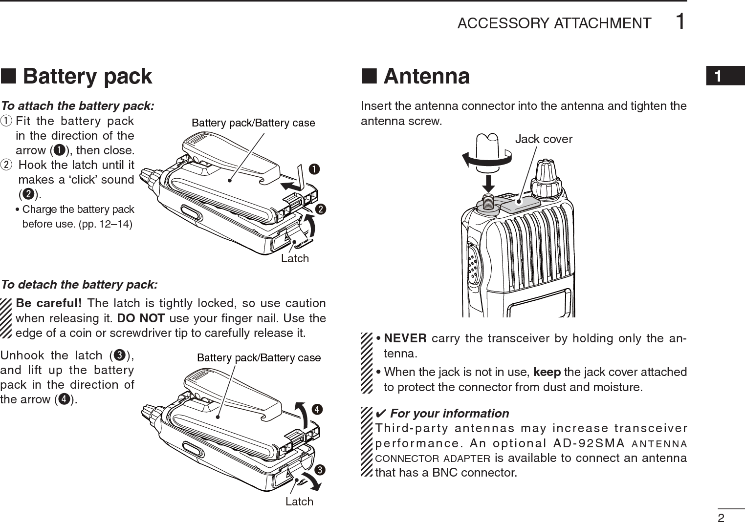
![306MEMORY/CALL CHANNELS12345678910111213141516171819N Selecting a memory channelD Using [DIAL]q Push [V/M/C] to select the memory mode.• Pushing [V/M/C] toggles between the VFO mode, the memory channel mode, call channel mode and weather channel mode*.*Only the U.S.A. version transceiver.w Rotate [DIAL] to select a desired memory channel.• Only programmed channels are displayed.[DIAL] AppearsRotate [DIAL] to selectthe memory channel.D Using the Numeral keysq Push [V/M/C] to select the memory mode.• Pushing [V/M/C] toggles between the VFO mode, the memory channel mode, call channel mode and weather channel mode*.*Only the U.S.A. version transceiver.w Use the numeral keys to enter 3 digits to select a desired memory channel.• The blank channels are also selectable.• Example— selecting memory channel “25”Push [V/M/C], then push [0],[2],[5].AppearsNumeralkeysThe entered memorychannel is selected.](https://usermanual.wiki/ICOM-orporated/325300/User-Guide-1227495-Page-37.png)
![316MEMORY/CALL CHANNELSqPush [V/M/C] to select the VFO mode.wSet a desired frequency:± Select a desired band with [BAND].± Set a desired frequency with [DIAL].± Or set a desired frequency with keypad directly. In this case, the band and frequency settings with [BAND] and [DIAL] as above are not required.±Set other data (e.g. frequency offset, duplex direction, tone squelch, etc.), if desired.e Push and hold [S.MW](V/M/C) for 1 sec. to enter the select memory write mode.• 1 short and 1 long beep sound.•“ ” icon and memory channel number blink.rRotate [DIAL] to select a desired channel.• Call channels (C0, C1), VFO and scan edge channels (0A/0b to 24A/24b), as well as regular memory channels, can be pro-grammed in this way.tPush and hold [S.MW](V/M/C) for 1 sec. to program.• 3 beeps sound.• Memory channel number automatically increases when continu-ing to push [S.MW](V/M/C) for 1 sec. after programming.NOTE: Push [H/M/L] to cancel to program and exit the select memory write mode before memory programming is finished.[DIAL]The VFO mode Enter the select memory write mode.to select channel 11.RotatePush and hold for 1 sec.Return to the VFO mode.Push and hold for 1 sec. to program.[EXAMPLE]: Programming 145.440 MHz into memory channel 11 (a blank channel).Channel 11NMemory channel programming](https://usermanual.wiki/ICOM-orporated/325300/User-Guide-1227495-Page-38.png)
 for 1 sec. to enter the select memory write mode.• 1 short and 1 long beep sound.•“ ” icon and memory channel number blink.wRotate [DIAL] to select a desired memory channel.e Push [SET] to select “bAnk” item.• Bank group and channel number are displayed if the selected memory channel has already been assigned to a bank.[DIAL]Pushr Rotate [DIAL] to select a desired bank group from “A” to “Z.”[DIAL]t Push [BAND] to select the bank channel digit, then rotate [DIAL] to select the bank channel number from “00” to “99.”• Push [BAND] to toggle the bank group selection and bank chan-nel selection.[DIAL]Rotatey Push and hold [S.MW](V/M/C) for 1 sec. to assign the channel to the bank.• Return to the previous indication before entering the select memory write mode.](https://usermanual.wiki/ICOM-orporated/325300/User-Guide-1227495-Page-39.png)
![336MEMORY/CALL CHANNELSN Memory bank selectionq Push [V/M/C] to select the memory mode.w Push [BAND] to enter the bank selection mode.e Rotate [DIAL] to select a desired bank (A to Z), then push [BAND].• Only programmed banks are displayed.• Also regular memory channel can be selected.[DIAL]PushRotateBank channel is displayed.Regular memorychannelis displayed.Pushr Rotate [DIAL] to select the bank channel.• Only programmed channels are displayed.[DIAL]Bank channel is selected.](https://usermanual.wiki/ICOM-orporated/325300/User-Guide-1227495-Page-40.png)
![346MEMORY/CALL CHANNELS12345678910111213141516171819N Programming memory/bank/scan nameEach memory channel can be programmed with an alpha-numeric channel name for easy recognition and can be indi-cated independently by channel. Names can be a maximum of 6 characters.NOTE: Scan name indication can be turned ON or OFF in the Initial set mode. (p. 34)qPush [V/M/C] to select the memory mode.w Push and hold [S.MW](V/M/C) for 1 sec. to enter the select memory write mode.• 1 short and 1 long beep sound.•“ ” icon and memory channel number blink.eRotate [DIAL] to select a desired memory channel.• Select Call channels (C0 or C1) or scan edge channels (0A/0b to 24A/24b) to program a call channel name or scan name, re-spectively.r Push [SET] repeatedly to select “b nAmE,” “m nAmE” or “S nAmE” when programming the bank name, the memory name or the scan name, respectively.t Push and hold [SET] for 1 sec. to enter the name program-ming mode.• After selecting the name to be programmed, a cursor blinks for the first character.y Rotate [DIAL] to select a desired character.• The selected character blinks.• Push [BAND] to move the cursor right; push [SET] to move the cursor left. u Repeat step y until a desired channel name is pro-grammed.i Push and hold [S.MW](V/M/C) for 1 sec. to set the name and exit channel name programming state.• 3 beeps sound.NOTE: Only one bank name can be programmed into each bank. Therefore, the previously programmed bank name will be displayed when bank name indication is selected. Also, the programmed bank name is assigned for the other bank channels automatically.D Usable characters(A) (b) (C) (d) (E) (F) (G) (H) ( I ) (J) (k) (L) (m)(n) (O) (P) (q) (R) (S) (t) (U) (V) (W)(9)(0) (1) (2) (3) (4) (5) (6) (7) (8)(+) (:)(=) (()())()(X) (y) (Z)(-) (/)(Space)](https://usermanual.wiki/ICOM-orporated/325300/User-Guide-1227495-Page-41.png)
![356MEMORY/CALL CHANNELSNProgramming memory/bank/scan name (continued)[EXAMPLE]: Programming the bank name “VHF” into the scan edge channel 1ANSelecting memory/bank name indicationDuring memory mode operation, either the programmed memory name or bank name can be displayed.q While continuing to push [SET], turn the power ON to enter the Initial set mode.w Rotate [DIAL] to select the memory name item, then rotate [VOL] to set the memory name indication setting.• “OFF” : Memory name indication is turned OFF.• “On” : Activates the memory name indication. (default)[VOL][DIAL] Memory name settinge Push [ ] to return to the frequency display.Push and holdfor 1 sec.Push and holdfor 1 sec.Enter the select memorywrite mode.Push repeatedlyto select “b nAmE*2.”Push and holdfor 1 sec. to program.During memory mode, rotateto select scan edge channel 1A.Rotate to select “V,”then push .Select “H” and “F”with and .*1 S nAmE can be set for scan edge channels only.*2 b nAmE can be set for bank assigned channels only.Select “m nAmE” or “S nAmE*1” when programming the memoryname or the scan name, respectively.](https://usermanual.wiki/ICOM-orporated/325300/User-Guide-1227495-Page-42.png)
![366MEMORY/CALL CHANNELS12345678910111213141516171819NDisplay typeDuring memory mode operation, the transceiver has 3display types to suit your operating style. Set the display type in the Initial set mode.q While continuing to push [SET], turn the power ON to enter the Initial set mode.w Rotate [DIAL] to select the display mode item, then rotate [VOL] to set the display type from “FREq,” “CH” or “PRIV.”[VOL][DIAL] Display mode settinge Push [ ] to return to the frequency display.“Frequency display”Displays the programmed fre-quency. (default)“Channel number display”Displays the memory chan-nel number. Only programmed memory channels are displayed, and modes other than the memory mode cannot be selected.• When the channel number display type is selected, only the following functions can be performed.- Scan function (p. 44) - Output power setting (p. 22)- Monitor function (p. 17) - Key lock function (p. 21)- DTMF transmit function (p. 66)- The scan pause timer setting, the scan resume timer setting, the DTMF memory selection, the mic gain setting and the VOX gain setting in the Set mode.“Private channel display”Displays the memory channel number. Only programmed mem-ory channels 0 to 5 are displayed, and modes other than the memory mode cannot be selected.• When the private channel display type is selected, only the following functions can be performed.- Output power setting (p. 22) - Monitor function (p. 17)- Key lock function (p. 21) - DTMF transmit function (p. 66)](https://usermanual.wiki/ICOM-orporated/325300/User-Guide-1227495-Page-43.png)
![376MEMORY/CALL CHANNELSN Copying memory/call contentsThis function transfers a memory channel’s contents to VFO (or another memory/call channel). This is useful when search-ing for signals around a memory channel frequency and for recalling the frequency offset, subaudible tone frequency etc.D Memory/call¶VFOqSelect the memory (call) channel to be copied.±Push [V/M/C] repeatedly to select the memory mode or the call channel mode, then rotate [DIAL] to select a desired channel.w Push and hold [S.MW](V/M/C) for 1 sec. to enter the select memory write mode.• 1 short and 1 long beep sound.•“ ” icon and memory channel number blink.eRotate [DIAL] to select “VFO.”r Push and hold [S.MW](V/M/C) for 1 sec. to write the se-lected channel contents to the VFO mode.• Returns to the VFO mode automatically.Pushing and holding [S.MW](V/M/C) for 2 seconds at step w, will also copy the memory contents to VFO. In this case, steps e and r are not necessary.DMemory/call¶memory/callqSelect the memory (call) channel to be copied.±Push [V/M/C] repeatedly to select the memory mode or the call channel mode, then rotate [DIAL] to select a desired channel.w Push and hold [S.MW](V/M/C) for 1 sec. to enter the select memory write mode.• 1 short and 1 long beep sound.•“ ” icon and memory channel number blink.• Do not hold [S.MW](V/M/C) for more than 2 seconds otherwise the memory contents will be copied to the VFO mode.eRotate [DIAL] to select the target memory (call) channel.rPush and hold [S.MW](V/M/C) for 1 sec. again to copy.[DIAL]Memory mode Enterthe select memory write mode.to select “VFO.”RotatePush and hold for 1 sec.“VFO” is selected. Return to the VFO mode.Push and hold for 1 sec.[EXAMPLE]: Copying memory channel 11 to the VFO mode.](https://usermanual.wiki/ICOM-orporated/325300/User-Guide-1227495-Page-44.png)
 for 1 sec. to enter the select memory write mode.• 1 short and 1 long beep sound.•“ ” icon and memory channel number blink.• Do not hold [S.MW](V/M/C) for more than 2 seconds otherwise the memory contents will be copied to the VFO mode.w Rotate [DIAL] to select a desired memory channel to be cleared.e Push [SET] repeatedly to select “CLEAR.”r Push and hold [S.MW](V/M/C) for 1 sec. to clear the con-tents.• 3 beeps sound.• The cleared channel changes to blank channel• Return to the select memory write mode.— Memory channel number blinks. Push [H/M/L] to exit the select memory write mode.NOTE: Be careful!— the contents of cleared memories CANNOT be recalled.[DIAL]The VFO mode Enter the select memory write mode.to select a desired channel.RotatePush and hold for 1 sec.Channel 14Push repeatedly to select “CLEAR.”Push and hold for 1 sec to clear and return to the VFO mode.[EXAMPLE]: Clearing memory channel 14.NMemory clearing](https://usermanual.wiki/ICOM-orporated/325300/User-Guide-1227495-Page-45.png)
![396MEMORY/CALL CHANNELSN Erasing/transferring bank contentsThe bank contents of programmed memory channels can be cleared or reassigned to another memory bank.INFORMATION: Even if the memory bank contents are cleared, the memory channel contents still remain programmed.q Select a desired bank contents to be transferred or erased from the bank. (p. 33)±Push [BAND] to enter the memory bank selection mode.±Rotate [DIAL] to select a desired memory bank group, then push [BAND].±Rotate [DIAL] to select the bank channel.[DIAL]w Push [S.MW](V/M/C) for 1 sec. to enter the select memory write mode.• 1 short and 1 long beeps sound.• Displays the original memory channel number automatically, and then “ ” icon and memory channel number blink.• Do not hold [S.MW](V/M/C) for more than 2 seconds, otherwise the memory contents will be copied to VFO.e Push [SET] repeatedly to select “bAnk.”r Push [BAND] to toggle the bank channels selection or the bank group selection.t Rotate [DIAL] to select a desired bank group or channel to be transferred.• Select “– – – –” display when erasing the contents from the bank.[DIAL]To transfer the bank contentsto ch 11 in Bank b.To eraseBank channel is displayed.is displayed.y Push [S.MW](V/M/C) for 1 sec. to erase/transfer the bank contents.](https://usermanual.wiki/ICOM-orporated/325300/User-Guide-1227495-Page-46.png)
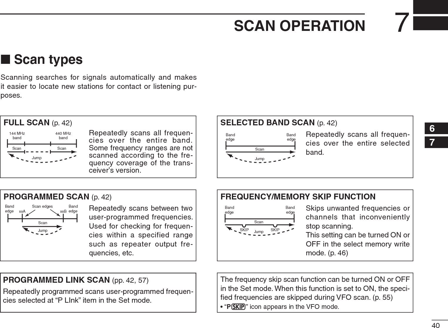
![N Full/band/programmed scan qPush [V/M/C] to select the VFO mode.• Select a desired frequency band with [BAND], if desired.wSet the squelch level.e Push and hold [SCAN](H/M/L) for 1 sec. to enter the scan-ning type selection.r Rotate [DIAL] to select a desired scanning type.• “ALL” for full scan; “bAnd” for band scan, “P-LInk x” for pro-grammed link scan (x= 0 to 9), “PROGxx (or scan name if pro-grammed)” for programmed scan (xx= 0 to 24; only programmed scan edge numbers are displayed), “dUP” (appears only when duplex operation is set) for duplex scan.[DIAL]Full scanBand scan Duplex scanProgrammed link scanPush and holdfor 1 sec.Programmed scanRotateSelectable from “0” to “9.”Selectable from “0” to “24,”if programmed.tPush [SCAN](H/M/L) to start the scan.• Scan pauses when a signal is received.• Rotate [DIAL] to change the scanning direction. This also causes the transceiver to resume scanning.• Push [V/M/C] to stop the scan.• Push [BAND] to change the band during band scan, or change the scan edge during programmed scan/program link scan.During full/band scan During programmed scanScan name can be displayed instead of “P-LInk x” for pro-gram link scan (x= 0 to 9), “PROGxx” for programmed scan (xx= 0 to 24) when scan name is programmed and set to ON in the Initial set mode.Scan name is not displayed during scan.427SCAN OPERATION12345678910111213141516171819](https://usermanual.wiki/ICOM-orporated/325300/User-Guide-1227495-Page-49.png)
![437SCAN OPERATIONN Scan edges programmingScan edges can be programmed in the same manner as memory channels. Scan edges are programmed into scan edges, 0A/0b to 24A/24b, in memory channels.qPush [V/M/C] to select the VFO mode.wSet a desired frequency:± Select a desired band with [BAND].± Set a desired frequency with [DIAL].±Program different frequencies in “1A” and “1b” respec-tively.±Set other data (e.g. frequency offset, duplex direction, tone squelch, etc.), if desired.e Push and hold [S.MW](V/M/C) for 1 sec. to enter the select memory write mode.• 1 short and 1 long beep sound.•“ ” icon and memory channel number blink.r Rotate [DIAL] to select a desired programmed scan edge channel from 0A to 24A.tPush and hold [S.MW](V/M/C) for 1 sec.• 3 beeps sound.• The other scan edge channel “b,” 0b to 24b, is automatically se-lected when continuing to push [S.MW](V/M/C) after program-ming.y To program a frequency for the other pair of scan edges, 0b to 24b, repeat steps w and r.• If the same frequency is programmed into a pair of scan edges, programmed scan will not function.[DIAL]The VFO mode Enterthe select memory write mode.to selectRotatePush and holdfor 1 sec. “3A.”“3A” is selected. Return to the VFO mode.Push and holdfor 1 sec.[EXAMPLE]: Programming 145.300 MHz into scan edges 3A.](https://usermanual.wiki/ICOM-orporated/325300/User-Guide-1227495-Page-50.png)
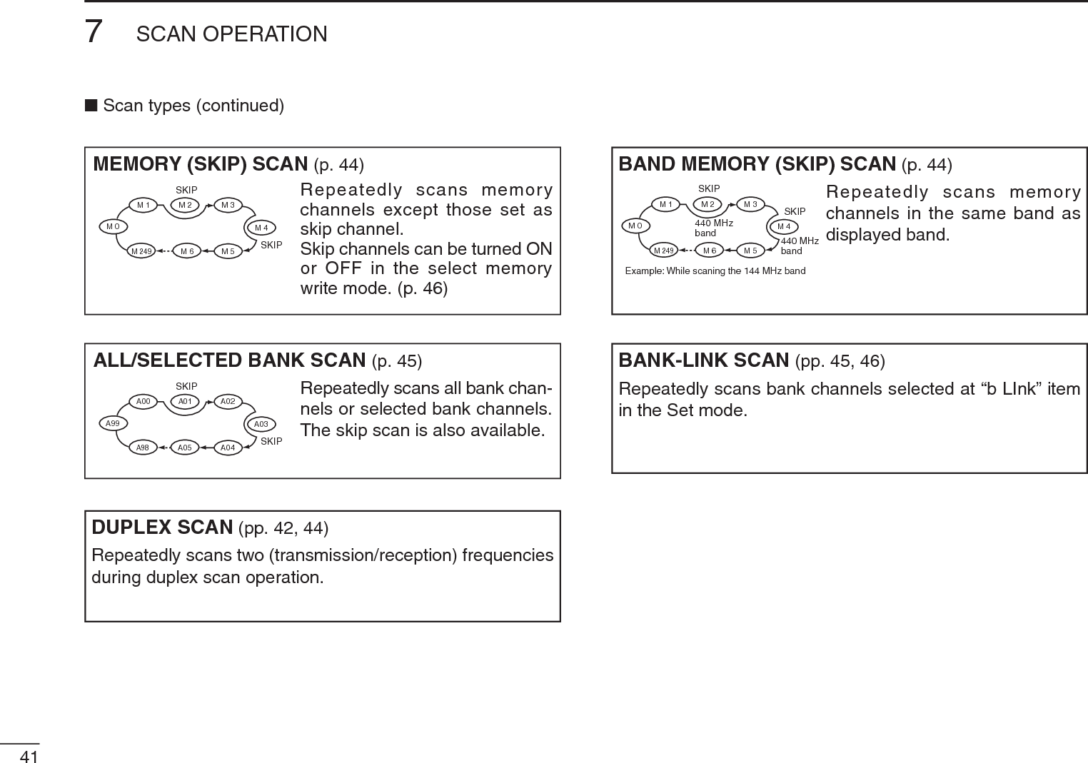
![N Memory scan IMPORTANT!: To perform memory scan, 2 or more mem-ory channels MUST be programmed, otherwise the scan will not start.q Push [V/M/C] repeatedly to select the memory mode.wSet the squelch level.e Push and hold [SCAN](H/M/L) for 1 sec. to enter the scan-ning type selection.r Rotate [DIAL] to select a desired scanning type.• “ALL” for all memory scan; “bAnd” for band memory scan, “dUP” (appears only when duplex operation is set) for duplex scan.[DIAL]All memory scanBand memory scanDuplex scanPush and holdfor 1 sec.RotatetPush [SCAN](H/M/L) to start the scan.• Scan pauses when a signal is received.• Rotate [DIAL] to change the scanning direction. This also causes the transceiver to resume scanning.• Push [V/M/C] to stop the scan.During memory scan447SCAN OPERATION12345678910111213141516171819](https://usermanual.wiki/ICOM-orporated/325300/User-Guide-1227495-Page-51.png)
![457SCAN OPERATIONN Memory bank scan IMPORTANT!: To perform memory bank scan, 2 or more bank channels MUST be programmed, otherwise the scan will not start.q Select memory bank mode.±Select the memory mode with [V/M/C].± Enter the memory bank selection mode with [BAND].±Set a desired bank (A to Z) with [DIAL], then push [BAND].wSet the squelch level.e Push and hold [SCAN](H/M/L) for 1 sec. to enter the scan-ning type selection.[DIAL]All bank scanBank link scanBank scanDuplex scanPush and holdfor 1 sec.RotateSelectable from “A” to “Z”if programmed.r Rotate [DIAL] to select a desired scanning type.• “ALL” for all bank scan; “b-LInk” for bank link scan or “bAnk-x” for bank scan (x= A to Z; programmed bank groups are only displayed.), “dUP” (appears only when duplex operation is set) for duplex scan.tPush [SCAN](H/M/L) to start the scan.• Scan pauses when a signal is received.• Rotate [DIAL] to change the scanning direction. This also causes the transceiver to resume scanning.• Push [V/M/C] to stop the scan.• Push [BAND] to change the bank during bank scan.During all bank/bank link scan During bank scanThe bank-link setting can be changed in the Set mode. See page 56 for details.Memory bank scan skips any memory channels in the se-lected bank that are set to “SKIP” or “PSKIP.”Memory bank scan stops at the first channel when all channels in a bank are set to “SKIP” or “PSKIP.”](https://usermanual.wiki/ICOM-orporated/325300/User-Guide-1227495-Page-52.png)
![N Skip channel/frequency settingMemory channels can be set to be skipped during memory skip scan. In addition, memory channels can be set to be skipped during both memory skip scan and frequency skip scan. This is useful to speed up the scan rate.qSelect a memory channel:± Push [V/M/C] to select the memory mode.±Rotate [DIAL] to select a desired channel to be a skip channel/frequency.[DIAL]w Push and hold [S.MW](V/M/C) for 1 sec. to enter the select memory write mode.e Push [SET] repeatedly to select “SkIP” item.Push repeatedly.r Rotate [DIAL] to select the skip condition from “SkIP,” “PSkIP” or “OFF” for the selected channel.• PSkIP : The channel is skipped during memory/bank scan and the programmed frequency is skipped during VFO scan, such as programmed scan.• SkIP : The channel is skipped during memory or bank scan. • OFF : The channel is scanned during any scan.t Push and hold [S.MW](V/M/C) for 1 sec. to store the skip condition into the memory.•“ ” or “P” icon appears, according to the skip selection in step r.“ ” appears “ ” appearsSkip channel setting Program skip setting467SCAN OPERATION12345678910111213141516171819](https://usermanual.wiki/ICOM-orporated/325300/User-Guide-1227495-Page-53.png)
![N Scan resume conditionD Scan pause timerThe scan pauses when receiving signals according to the scan pause time. It can be set from 2 to 20 seconds or un-limited.q Push [SET] to enter the Set mode.w Rotate [DIAL] to select the scan pause timer item.e Rotate [VOL] to select a desired scan pausing time from 2–20 seconds (2 seconds steps) or “HOLd.” • “2”–“20” : Scan pauses for 2–20 seconds while receiving a sig-nal.• “HOLd” : Scan pauses on a received a signal until it disap-pears.rPush [V/M/C] to return to the frequency display.D Scan resume timerThe scan restarts after the signal disappears according to the resume time. It can be set from 0–5 seconds or unlimited.q Push [SET] to enter the Set mode.w Rotate [DIAL] to select the scan pause timer item.e Rotate [VOL] to select a desired scan resume time from 0–5 seconds (1 second steps) or “HOLd.” • “0” : Scan restarts immediately after the signal disap-pears.• “1”–“5” : Scan restarts 1–5 seconds after the signal disap-pears.• “HOLd” : Scan remains paused on the received signal accord-ing to the scan pause timer even if it disappears. Ro-tate [DIAL] to resume manually.rPush [V/M/C] to return to the frequency display.Scan resume timer must be set shorter than the scan pause timer, otherwise this timer does not activate.477SCAN OPERATION](https://usermanual.wiki/ICOM-orporated/325300/User-Guide-1227495-Page-54.png)
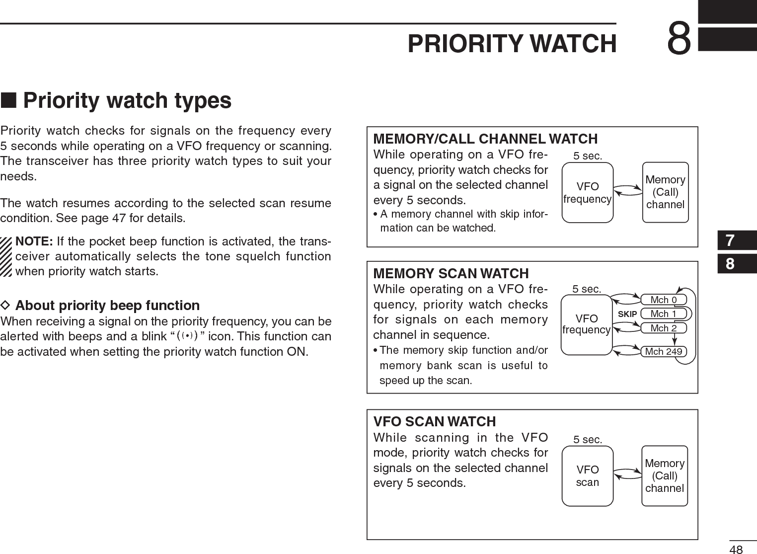
 for 1 sec. to enter the scan type selection mode.±Rotate [DIAL] to select a desired scan type, then push [SCAN](H/M/L) again to start the memory/bank scan.e Push [SET] to enter the Set mode.r Rotate [DIAL] to select the priority watch set item.t Rotate [VOL] to select “On.”• Select “bELL” if the priority beep function is desired.y Push [V/M/C] to exit the Set mode and start the watch.• “PRIO” icon appears.• The transceiver checks the memory/bank channel(s) or call channel every 5 seconds.• The watch resumes according to the selected scan resume con-dition. (p. 47)u Push [V/M/C] to cancel the watch.Monitors VFO frequency for 5 sec.Pauses on a memoryor call channel when a signal is received.• During priority watchSounds beep tone and blinks “S” icon when a signal is received on a memory or call channel.• During priority watch with priority beep](https://usermanual.wiki/ICOM-orporated/325300/User-Guide-1227495-Page-56.png)
 for 1 sec. to enter the scan type selection.±Rotate [DIAL] to select a desired scan type, then push [SCAN](H/M/L) again to start memory/bank scan.w Push [SET] to enter the Set mode.e Rotate [DIAL] to select the priority watch set item.r Rotate [VOL] to select “On.”• Select “bELL” if the priority beep function is desired.t Push [V/M/C] to exit the Set mode and start the watch.• “PRIO” icon appears.y Push and hold [SCAN](H/M/L) for 1 sec. to enter scan type selection mode.u Rotate [DIAL] to select a desired scan type from “ALL,” “bAnd,” “P-LInk x (x= 0–9),” “PROGxx (xx= 0–24)” and “dUP.” iPush [SCAN](H/M/L) to start the VFO scan watch.• The transceiver checks the memory/bank channel(s) or call channel every 5 seconds.• The watch resumes according to the selected scan resume con-dition. (p. 47)i Push [V/M/C] to cancel the watch.Searches VFO frequencies for 5 sec.Pauses on a memoryor call channel when a signal is received.• During priority watchSounds beep tone and blinks “S” icon when a signal is received on a memory or call channel.• During priority watch with priority beep](https://usermanual.wiki/ICOM-orporated/325300/User-Guide-1227495-Page-57.png)
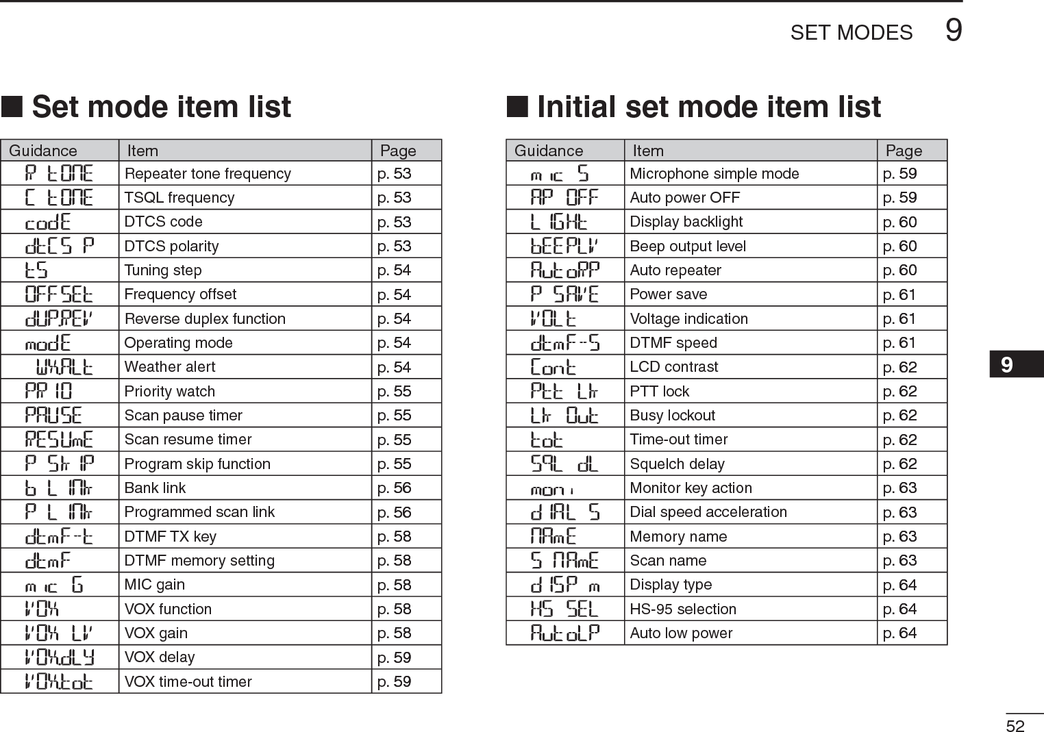
![51SET MODES9N GeneralD Entering Set mode and operationThe Set mode is used to change the settings of the trans-ceiver’s functions.q Push [SET] to enter the Set mode.w Rotate [DIAL] to select the desired set item.e Rotate [VOL] to set the desired value or setting.rPush [V/M/C] to return to frequency display, or repeat steps w and e to set another items.[VOL][DIAL]D Entering Initial set mode and operationThe Initial set mode can be accessed at power ON and al-lows you to set seldom-changed settings, to suit your prefer-ence and operating style.qWhile continuing to push [SET], turn the power ON to enter the Initial set mode.w Rotate [DIAL] to select the desired set item.e Rotate [VOL] to set the desired value or setting.rPush [] to return to the frequency display, or repeat steps w and e to set another items.[VOL][DIAL]](https://usermanual.wiki/ICOM-orporated/325300/User-Guide-1227495-Page-58.png)
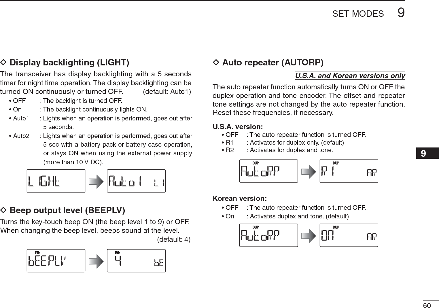
![559SET MODESD Priority watch (PRIO)Activates priority watch or priority watch with alert (Bell). (default: OFF)• OFF : The priority watch is turned OFF.• On : The transceiver checks the memory channel frequency every 5 seconds.• bELL : The transceiver checks the memory channel frequency every 5 seconds. You can be alerted with beeps and blinking “S.”D Scan pause timer (PAUSE)Selects the scan pause time. When receiving signals, the scan pauses according to the scan pause timer. (default: 10)• 2–20 : Scan pauses for 2–20 seconds while receiving a signal in 2 seconds steps.• HOLd : Scan pauses on a received signal until it disappears. D Scan resume timer (RESUME)Selects the scan resume time from a pause after the received signal disappears. (default: 2)• 0 : Scan resumes immediately after the received signal disappears.• 1–5 : Scan pauses 1–5 seconds after the received signal dis-appears.• HOLd : Scan remains paused on the received signal according to the scan pause timer even if it disappears. Rotate [DIAL] to resume manually.Scan resume timer must be set shorter than scan pause timer (previous item), otherwise this timer cannot be acti-vated.D Program skip scan (P SKIP)Sets programmed skip scan function ON (default) or OFF for VFO scan (full scan, programmed scan, etc.) operation.](https://usermanual.wiki/ICOM-orporated/325300/User-Guide-1227495-Page-62.png)
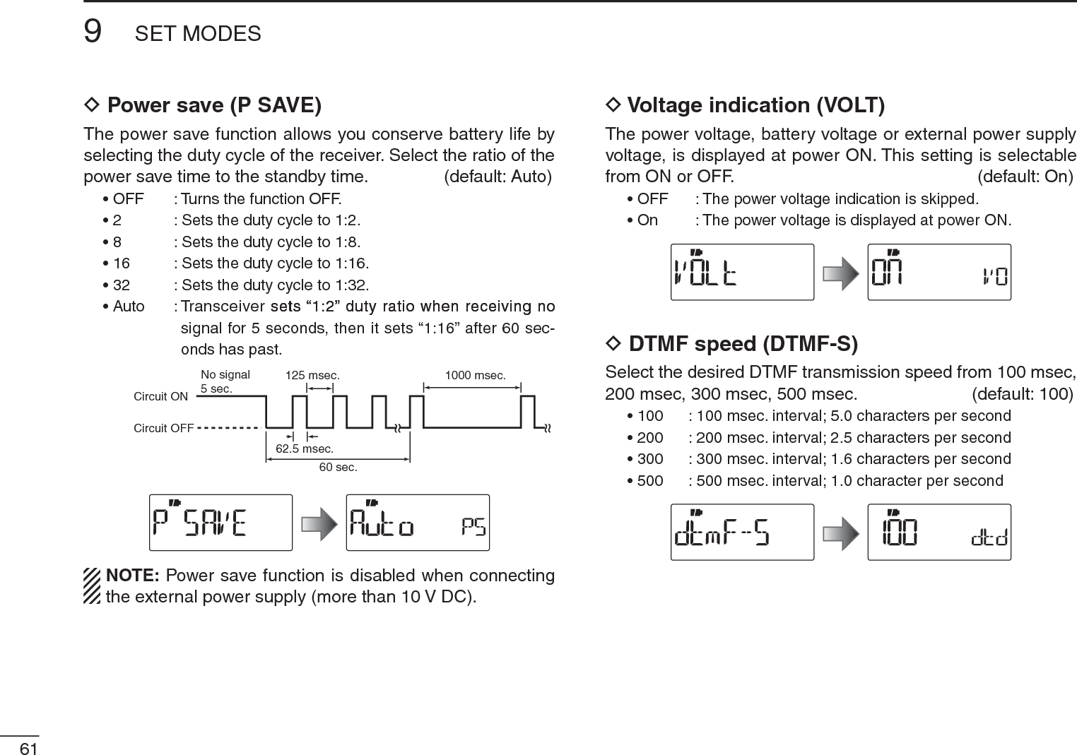
![569SET MODES12345678910111213141516171819D Memory bank link function (B LINK)Sets the memory bank link function ON (default) or OFF. The link function provides continuous bank scan, scanning all channels in the selected banks during bank scan.• Bank link settingqPush and hold [SET] for 1 sec. to enter the bank link setting.wRotate [DIAL] to select the bank that you want to change the link setting.eRotate [VOL] to select the option. Setting is OFFSetting is ONrRotate [DIAL] to select next bank and repeat steps wand e, or push [BAND] to exit the BANK link setting.D Program scan link function (P LINK)Sets the program scan link function. The link function pro-vides continuous program scan in the selected program scan number during program scan. Default settings for LInk0 to LInk9;PROG 1 to PROG 24 are linked, but PROG 0 is no-linked.• Confirming program scan linkqRotate [VOL] to select the program scan link number that you want to confirm.wPush and hold [SET] for 1 sec. to enter the program scan link setting.• “LInk” appears.ePush and hold [SET] for 1 sec., then rotate [DIAL] to confirm the linked program scans.rPush [BAND] to exit the program scan link setting.](https://usermanual.wiki/ICOM-orporated/325300/User-Guide-1227495-Page-63.png)
![579SET MODES• Program scan link settingqRotate [VOL] to select the program scan link number that you want to change.wPush and hold [SET] for 1 sec. to enter the program scan link setting.• “LInk” appears.eRotate [DIAL] to select the option, “Add” or “CLEAR.”rPush and hold [SET] for 1 sec., then rotate [DIAL] to select the desired program scan.• When “Add” is selected in step e, only non-linked program scans are displayed. When “CLEAR” is selected in step e, only linked program scans are displayed. tPush and hold [SET] for 1 sec. to set the program scan link setting.yRepeat steps r and t to add or clear the program scan to/from the link, or push [BAND] to exit the program link scan setting.• Program scan link name programmingqRotate [VOL] to select the program scan link number for which you want to program a name.wPush and hold [SET] for 1 sec. to enter the program scan link setting.• “LInk” appears.eRotate [DIAL] to select “nAmE.”rPush and hold [SET] for 1 sec. to enter the name programming.t Rotate [DIAL] to select the desired character, number, symbol or space; push [BAND] or [SET] to move the cur-sor right or left, respectively.y When the cursor is on the 6th digit, push [BAND] to pro-gram the scan link name and exit the setting.u Push [BAND] to exit the program link setting.iRepeat steps from q to u to program the program link scan name, or push [V/M/C] to exit the Set mode.](https://usermanual.wiki/ICOM-orporated/325300/User-Guide-1227495-Page-64.png)
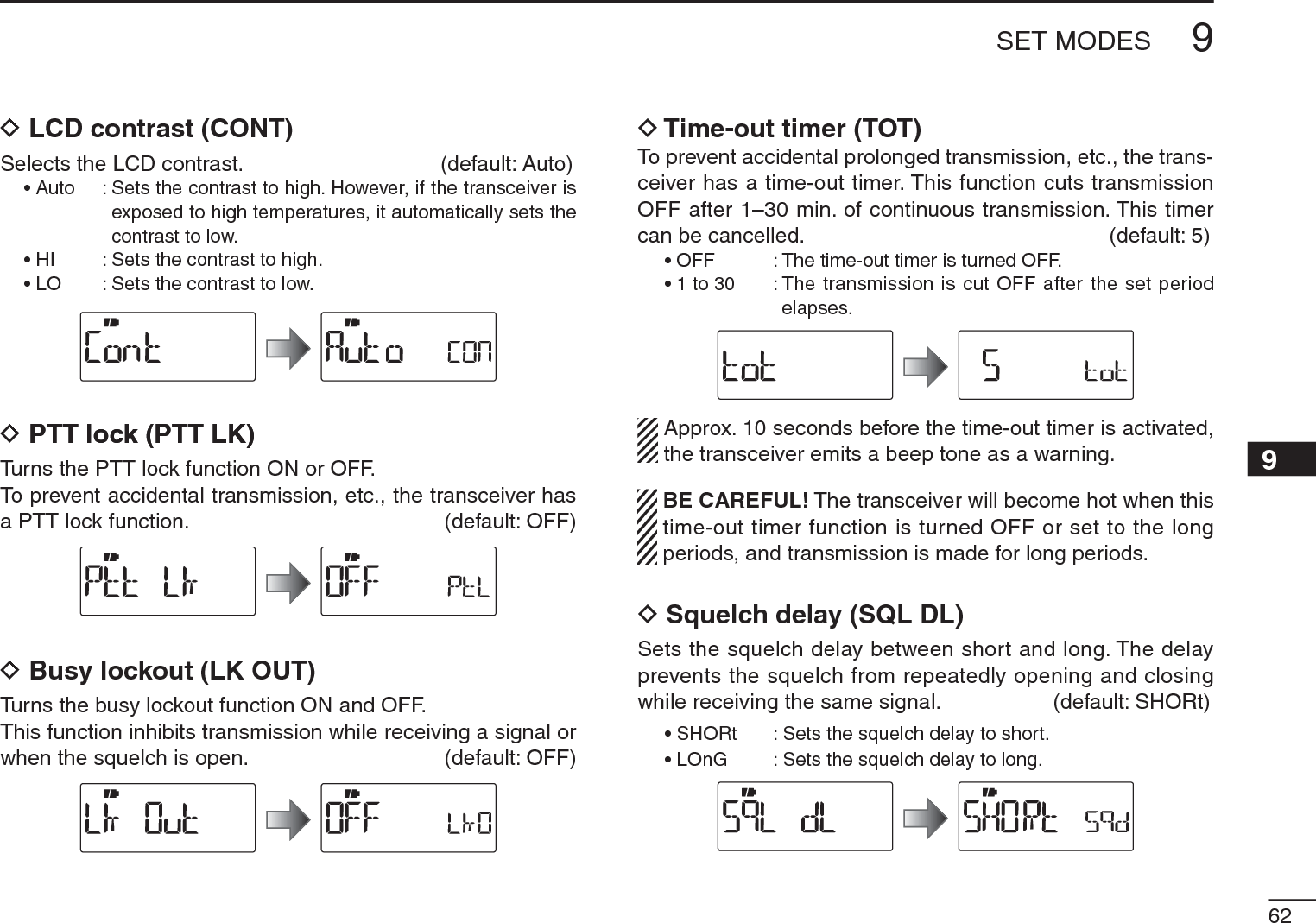
![589SET MODES12345678910111213141516171819D DTMF TX key (DTMF-T)Selects the method to transmit a DTMF code sequence. While continueing to push [PTT], push one of the keys, [0] to [9], [A](SET), [B](BAND), [C](H/M/L), [D](V/M/C), [1] (indica-tion: E) and [#] (indication: F). • KEy : Transmits the appropriate DTMF code assigned to the key. (default)• mEm : Transmits the programmed DTMF code sequence in the DTMF memory channel assigned to the key.• t-CALL : No DTMF code can be transmitted. However, while continuing to push [PTT], push [MONI](BAND) to transmit a 1750 Hz tone burst signal.DDTMF memory (DTMF)Program the DTMF memory channels. (p. 65)DMicrophone gain (MIC G)Sets the microphone gain to between 1 and 4 to suit your preference. Higher values make the microphone more sensi-tive to your voice. (default: 2)NOTE: When using the VOX function, we recommend setting the microphone gain to 3. However, you can adjust it to suit your operating environment (including the head-set performance you are using).DVOX function (VOX) (VOX)Turns the vox function ON or OFF. (p. 80) (default: On)DVOX gain (VOX LV) (VOX LV)Sets the VOX gain to between 1 and 10. Higher values make the VOX function more sensitive to your voice.To turn the VOX function OFF, select “OFF.” (default: 5)NOTE: Set the microphone gain before setting the VOX gain. See page 80 for details of the VOX function.](https://usermanual.wiki/ICOM-orporated/325300/User-Guide-1227495-Page-65.png)
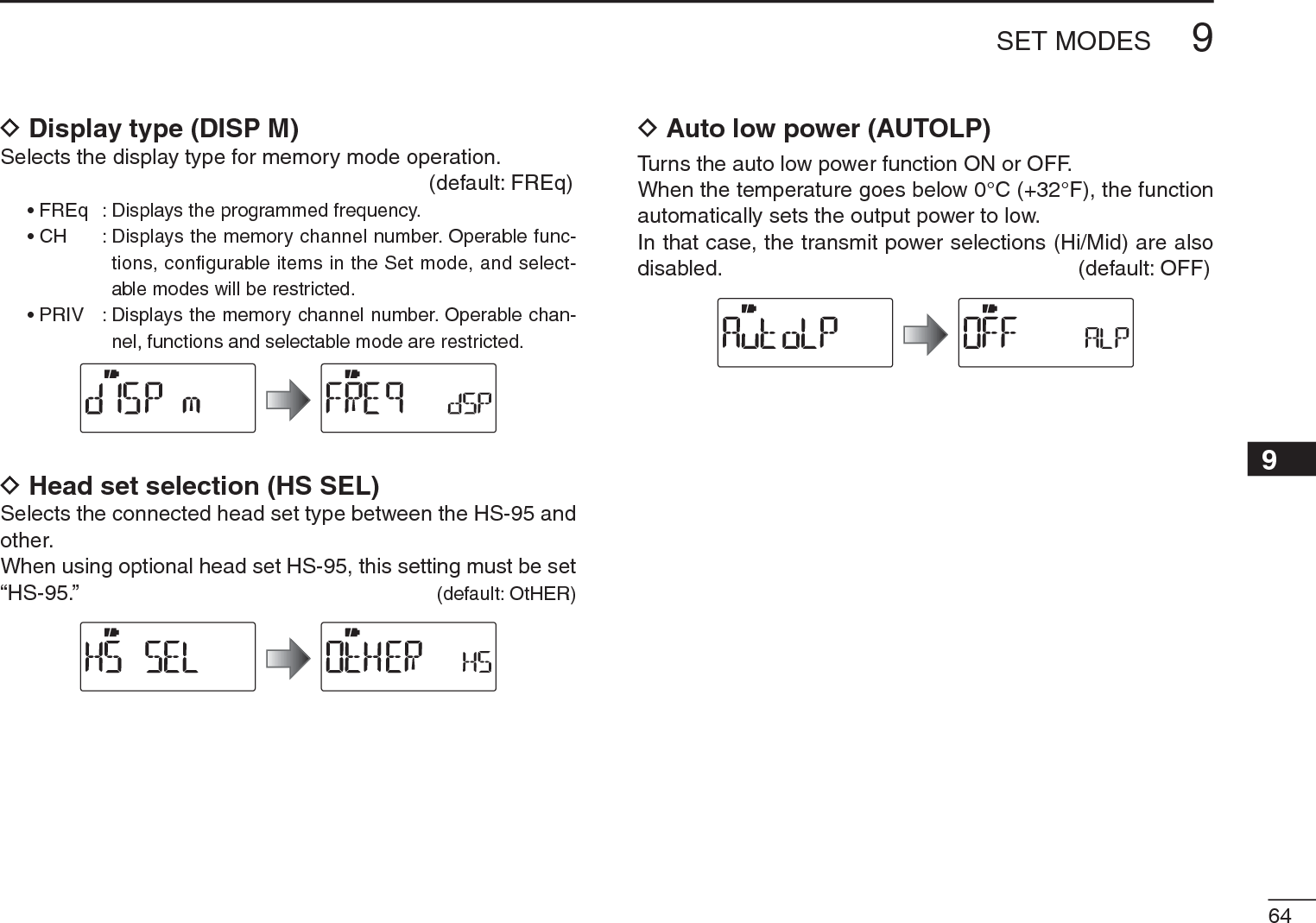
, can be set as a ‘sticky’ key. When set to the sticky condition, each push of [MONI](BAND) toggles the monitor function ON and OFF. (default: PUSH)• PUSH : Push and hold [MONI](BAND) to monitor the fre-quency.• HOLd : Push and hold [MONI](BAND) for 1 sec. to monitor the frequency and push again to cancel it.D Dial speed acceleration (DIAL S)The dial speed acceleration automatically speeds up the tun-ing dial speed when rotating [DIAL] rapidly. (default: On)• OFF : The dial speed acceleration is turned OFF.• On : The dial speed acceleration is tuned ON.D Memory name (NAME)The memory name is displayed during memory mode. (default: OFF)• OFF : The frequency of the selected memory channel is dis-played.• On : The pre-programmed memory name is displayed when the memory mode is selected.D Scan name (S NAME)The programmed scan, programmed link scan or bank name is displayed during the scan type selection. (default: On)• OFF : The programmed scan, programmed link scan or bank name is not displayed.• On : The programmed scan, programmed link scan or bank name is displayed.](https://usermanual.wiki/ICOM-orporated/325300/User-Guide-1227495-Page-70.png)
![65OTHER FUNCTIONS10DTMF codes are used for autopatching, accessing repeat-ers, controlling other equipment, etc. The transceiver has 16DTMF memory channels (d0–d9, dA, db, dC, dd, dE, dF) for storage of often-used DTMF codes of up to 24 digits.q Push [SET] to enter the Set mode.w Rotate [DIAL] to select the DTMF programming item.e Rotate [VOL] to select a desired DTMF memory channel.• If programmed, previously programmed DTMF code is dis-played.[VOL][DIAL]DTMF memory channelBlank channel indicationr Push and hold [SET] for 1 sec. to enter the programming mode.The cursor is blinking duringprogramming mode.t Rotate [VOL] to select the char-acters.• “0”–“9,” “A,” “b,” “C,” “d,” “E” and “F” are selectable.• Up to 24 digits can be programmed.• Push [BAND] to move the cursor right; push [SET] to move the cur-sor left.y Repeat step t until the desired code is input.Next display appears after 6th digit has been input.: 1st display : 2nd display: 3rd display : 4th display• If a digit is mistakenly programmed, push [SET] (or [BAND]) re-peatedly to select the digit, then rotate [VOL] to correct it.Or rotate [VOL] to select “_” to erase on and after the digits. Pro-grammed memories will be cleared by this operation on the 1st digit.y Push [BAND] twice to program the DTMF code and exit the programming mode.• After the 24th digit is input, the transceiver automatically stores the code sequence and returns to step e.uPush [V/M/C] to return to the frequency display.N Programming a DTMF code sequence[VOL]](https://usermanual.wiki/ICOM-orporated/325300/User-Guide-1227495-Page-72.png)
![6610OTHER FUNCTIONS12345678910111213141516171819The transceiver has 3 methods of transmitting a DTMF code sequence. Select a desired option in the Set mode.q Push [SET] to enter the Set mode.w Rotate [DIAL] to select the DTMF TX key item.[VOL][DIAL]e Rotate [VOL] to select a desired DTMF key setting.• kEy : Transmits the appropriate DTMF code assigned to the pushed key. (default)• mEm :Transmits the programmed DTMF code sequence in the DTMF memory channel assigned to the pushed key.• t-CALL : No DTMF code can be transmitted. However, while continuing to push [PTT], pushing [MONI](BAND) transmits a 1750 Hz tone burst signal.rPush [V/M/C] to return to the frequency display.DManual DTMF code transmissionFirst, set the DTMF TX key to “kEy” in the Set mode.±While continuing to push [PTT], push the desired keys to transmit a DTMF code sequence manually.•[0]–[9],[A](SET), [B](BAND), [C](H/M/L), [D](V/M/C), [1](.) or [#] sends “0”–“9,” “A,” “B,” “C,” “D,” “” or “#.”[PTT]DTMF code keysN Transmitting a DTMF code sequence](https://usermanual.wiki/ICOM-orporated/325300/User-Guide-1227495-Page-73.png)
![NTransmitting a DTMF code sequence (continued)DUsing a DTMF memory channelFirst, set the DTMF TX key to “mEm” in the Set mode.±While continuing to push [PTT], push one of the keys to transmit the programmed DTMF code sequence in the DTMF memory.• Pushing [0] to [9], [A](SET), [B](BAND), [C](H/M/L), [D](V/M/C), [M](.) or [#] transmits “d0”–“d9,” “dA,” “db,” “dC,” “dd,” “dE” or “dF.”D1750 Hz toneTo access some European repeaters, the transceiver must transmit a 1750 Hz tone burst signal. • This tone can be used as a ‘Call signal’ in countries out of Europe.First, set the DTMF TX key to “t-CALL” in the Set mode.±While continuing to push [PTT], push and hold [MONI](BAND) for 1 or 2 sec. to transmit a 1750 Hz tone burst signal.N Setting DTMF transfer speedThe DTMF transfer speed can be selected.q While continuing to push [SET], turn the power ON to enter the Initial set mode.w Rotate [DIAL] to select the DTMF transfer speed item, then rotate [VOL] to select the transfer speed. 100 : Transfer the DTMF tones at about 100 msec. per tone.200 : Transfer the DTMF tones at about 200 msec per tone. 300 : Transfer the DTMF tones at about 300 msec per tone.500 : Transfer the DTMF tones at about 500 msec per tone.e Push [] to return to the frequency display.6710 OTHER FUNCTIONS](https://usermanual.wiki/ICOM-orporated/325300/User-Guide-1227495-Page-74.png)
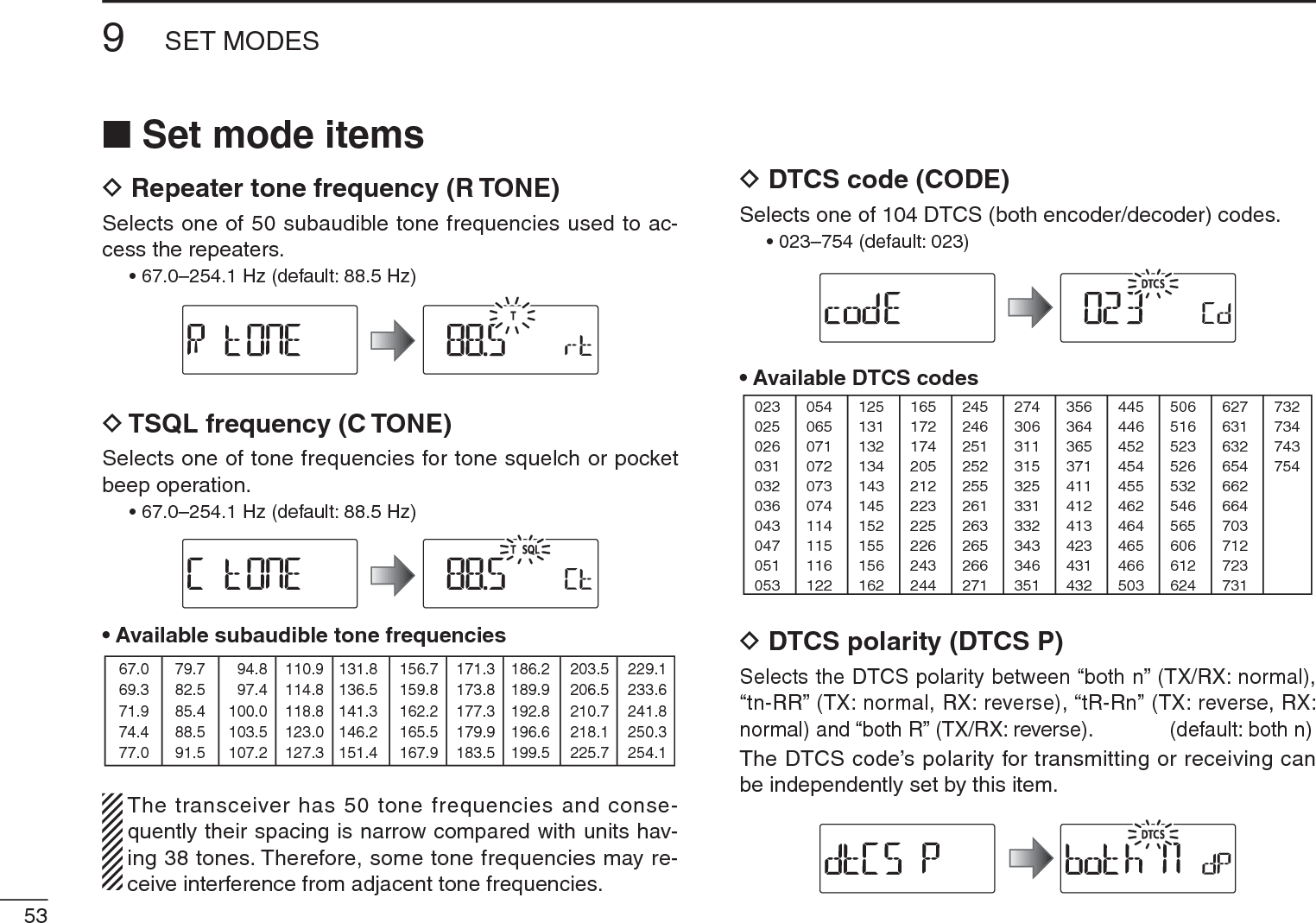
![6810OTHER FUNCTIONS12345678910111213141516171819NTone frequency and DTCS codeDTone and DTCS squelchesThe tone squelch (CTCSS) or DTCS squelch opens only when receiving a signal containing a matching subaudible tone or DTCS code, respectively. You can silently wait for calls from group members using the same tone or code. Separate tone frequencies can be set for repeater and tone squelch/pocket beep operation.DReverse tone/DTCS squelchThe reverse tone/DTCS squelch is convenient if you want to ignore a specific signal. The transceiver mutes the squelch when a signal with the matched tone or code is received. “T SQL-R” / “DTCS-R” is displayed when the reverse tone/DTCS squelch is set.DPocket beepThese functions use subaudible tones or DTCS codes for calling and can be used as a “common pager” to inform you that someone has called while you were away from the transceiver.DSetting subaudible tones for tone squelchq Push [SET] to enter the Set mode.w Rotate [DIAL] to select the CTCSS tone frequency item.[VOL][DIAL]e Rotate [VOL] to select a desired CTCSS tone frequency.• Each operating band and each memory channel have indepen-dent settings.• See page 53 for available tone frequencies for details.rPush [V/M/C] to return to the frequency display.](https://usermanual.wiki/ICOM-orporated/325300/User-Guide-1227495-Page-75.png)
![NTone frequency and DTCS code (continued)DSetting DTCS code for DTCS squelchq Push [SET] to enter the Set mode.w Rotate [DIAL] to select the DTCS code item.[VOL][DIAL]e Rotate [VOL] to select a desired DTCS code.• Each operating band and each memory channel have indepen-dent settings.• See page 53 for available DTCS codes for details.rPush [V/M/C] to return to the frequency display.DTCS phase can be selected in “dtCS-P” item. See next content for more details.DSetting DTCS polarityq Push [SET] to enter the Set mode.w Rotate [DIAL] to select the DTCS polarity item.[VOL][DIAL]e Rotate [VOL] to select a desired DTCS polarity mode.• bOtH n : Normal phase is used for both TX and RX. (Default)• tn-RR : Normal phase is used for TX; Reverse phase for RX.• tR-Rn : Reverse phase is used for TX; Normal phase for RX.• bOtH R : Reverse phase is used for both TX and RX.rPush [V/M/C] to return to the frequency display.6910 OTHER FUNCTIONS](https://usermanual.wiki/ICOM-orporated/325300/User-Guide-1227495-Page-76.png)
 for 1 sec. repeatedly to activate the tone or DTCS squelch. (T SQL or DTCS)• Subaudible tone encoder “T,” pocket beep (tone squelch) “ST SQL,” tone squelch “T SQL,” DTCS beep “SDTCS,”DTCS squelch “DTCS,” tone squelch reverse “T SQL-R,” DTCS squelch reverse “DTCS-R” and no tone operation are select-able in order.e Operate the transceiver in the normal way.r When the received signal includes a matching tone/code, the squelch opens and the signal can be heard.When the pocket beep function is activated, the trans-ceiver also emits beep tones and blinks ““S.”• When the received signal’s tone/code does not match, tone/DTCS squelch does not open, however, the S-indicator shows signal strength.• To open the squelch manually, push and hold [MONI](BAND).t Push [PTT] to answer or push and hold [MONI](BAND) for 1 sec. to stop the beeps and blinking.No tone operation Subaudible tone encoderTone squelchPocket beepDTCS beep DTCS squelchTone squelch (reverse) DTCS squelch (reverse)](https://usermanual.wiki/ICOM-orporated/325300/User-Guide-1227495-Page-77.png)
 for 1 sec. repeatedly to activate the repeater tone, tone squelch or DTCS squelch. (T, T SQL or DTCS)e Push and hold [T.SCAN](#) for 1 sec. to start the tone scan.• To change the scanning direction, rotate [DIAL].r When the tone frequency or DTCS code is decoded, the set mode contents are programmed with the frequency or code.• The tone scan pauses for the set period in scan pause timer (p. 47) when a tone frequency or DTCS code is detected.• The decoded tone frequency is used for the repeater tone fre-quency when any tone setting, such as repeater tone or tone squelch is OFF.• The decoded tone frequency is used for the tone squelch fre-quency when the tone squelch is ON.• The decoded DTCS code is used for the DTCS squelch code when the DTCS squelch is ON.Tone scan for repeater toneTone scan for tone squelchtPush [V/M/C] to stop the scan.• If the scan is cancelled before the transceiver detects the tone or code, the set mode contents are not changed.• The detected tone is used for temporary operation only. The stored tone setting in memory or call channel won’t be changed.7110 OTHER FUNCTIONSNOTE: Tone frequency is over-written automatically when it corresponds with the scanning tone frequency in tone squelch mode. However, it is not over-written in memory or call channel mode.](https://usermanual.wiki/ICOM-orporated/325300/User-Guide-1227495-Page-78.png)
![7210OTHER FUNCTIONS12345678910111213141516171819There are 10 weather channels for monitoring weather broadcasts from the NOAA (National Oceanic and Atmospheric Administration).D Weather channel selectionq Push [V/M/C] repeatedly to select weather channel mode.• “WX” and the weather channel number appear.wRotate [DIAL] to select a desired weather channel.e Push [V/M/C] to return to the previous frequency or mem-ory channel.[DIAL]Weather channel indicationPush and hold [SCAN](H/M/L) for 1 sec. activates the weather channel scan. Push [SCAN](H/M/L) again to stop the scan.D Weather alert functionNOAA broadcast stations transmit weather alert tones be-fore important weather announcements. When the weather alert function is turned ON, the selected weather channel is monitored every 5 seconds for the announcement. When the alert signal is detected, the “ALT” and the WX channel in-dications are displayed alternately and a beep sounds until the transceiver is operated. The previously selected (used) weather channel is checked periodically during standby or while scanning.qSelect the desired weather channel.w Push [SET] to enter the Set mode.e Rotate [DIAL] to select the weather alert setting item, then rotate [VOL] to select “On.”rPush [V/M/C] to return to the weather channel display.tSet the desired stand-by condition.• Select VFO, memory or call channel.• Scan or priority watch operation can also be selected.NWeather channel operation U.S.A. version only](https://usermanual.wiki/ICOM-orporated/325300/User-Guide-1227495-Page-79.png)
![7410OTHER FUNCTIONS12345678910111213141516171819N Cloning functionThe IC-T70A/T70E has transceiver-to-transceiver data clon-ing capability. This function is useful when you want to copy all of the programmed contents from one IC-T70A/T70E to another.• An optional OPC-474 CLONING CABLE is required.q Turn the transceiver’s power OFF, then connect an optional OPC-474 between both [SP] jacks.OPC-474to the [SP] jack to the [SP] jackw While continuing to push [V/M/C], push and hold []for 1 sec. to enter the cloning mode.• “CLOnE m” appears.ePush [PTT] on the “master” transceiver.• “CL OUt m” appears and the bar meter shows that cloning is taking place.• After the cloning is completed, the display returns to “CLOnE m.”rPush and hold [ ] for 1 sec. to turn power OFF.The optional CS-T70 CLONING SOFTWARE is also available to clone/edit contents with a PC (for Microsoft® Windows®2000/XP, Windows Vista® or Windows® 7) using ICF format files.PCOPC-478(RS-232C type)OPC-478UC(USB type) to USB portto RS-232Cportto the[SP] jack](https://usermanual.wiki/ICOM-orporated/325300/User-Guide-1227495-Page-81.png)
![7510 OTHER FUNCTIONSN ResettingThe display may occasionally display erroneous information (e.g. when first applying power). This may be caused externally by static electricity or by other factors.If this problem occurs, turn power OFF. After waiting a few seconds, turn power ON again. If the problem persists, per-form either or both procedures below.• All resetReset the CPU before operating the transceiver for the first time, or if the internal CPU malfunctions due to static electricity, etc. All reset clears all pro-gramming and returns all settings to their factory defaults. • Partial resetUse Partial reset if you want to initial-ize the operating conditions (VFO frequency, VFO settings, set mode contents) without clearing the memory contents.D All resetq Push and hold [ ] for 1 sec. to turn power OFF.w While continuing to push [SET],[BAND] and [H/M/L], then turn power ON to reset the CPU.• “CLEAR” appears when resetting the CPU (See the illustration below).CAUTION: Resetting the CPU re-turns all programmed contents to their default settings.D Partial resetq Push and hold [ ] for 1 sec. to turn power OFF.w While continuing to push [V/M/C], then turn power ON to partially reset the transceiver.NOTE: No message appears on the display after the partial reset is done.All resetPartial reset](https://usermanual.wiki/ICOM-orporated/325300/User-Guide-1227495-Page-82.png)
![7611TROUBLESHOOTING12345678910111213141516171819If your transceiver seems to be malfunctioning, please check the following points before sending it to a service center.PROBLEM POSSIBLE CAUSE SOLUTION REF.Transceiver does not turn ON.• The battery is exhausted.• The battery polarity is reversed.• Loose connection of a battery pack (case).• Charge the battery pack, or replace the batteries.• Check the battery polarity.• Clean battery terminals.pp. 2, 11–14p. 11–No sound comes from the speaker.• Volume level is too low.• An external speaker or a cloning cable is con-nected to the [SP] jack.• Rotate [VOL] to adjust to a desired level.• Check the external speaker connection or remove the cloning cable. p. 16–Transmitting is impossible. • A frequency outside of the 144/400 MHz ama-teur bands is set.• The PTT lock function is activated.• The heat protection is activated, and “Hot” is displayed.• Set the frequency within 144/400 MHz amateur bands.• Set the PTT lock function OFF in the Initial set mode.• Cool down the transceiver.p. 20p. 62p. 23Transmitting using the VOX function is impossible.• The VOX gain is set to OFF or too low.• The microphone gain is too low.•Set the VOX gain to a suitable level.•Set the microphone gain to a suitable level.p. 81p. 58Contacting with another station is impossible.• Different tone or code is used for the tone/DTCS squelch.• Check the tone/DTCS by performing a tone scan. p. 71Frequency cannot be set. • The lock function is activated.• The memory mode, Call channel mode, or weather channel mode is selected.• Push and hold [](SET) for 1 sec. to cancel the lock function.• Push [V/M/C] repeatedly to select the VFO mode.p. 21p. 18A program scan does not start.• The memory mode, Call channel mode, or weather channel mode is selected.• The same frequency has been programmed in the scan edge channels, “1A” and “1b.”• Push [V/M/C] repeatedly to select the VFO mode.• Programming different frequencies in the scan edge channels.p. 18p. 43A memory scan does not start.•The VFO mode or Call channel mode is selected.• Only one or no memory channel has been pro-grammed.•Push [V/M/C] repeatedly to select the memory mode.• Program 2 or more memory channels.p. 18p. 31The displayed frequency is erroneous.• The CPU has malfunctioned.• External factors have caused a fault.• Reset the transceiver.• Remove and re-attach the battery pack/case.p. 75p. 2](https://usermanual.wiki/ICOM-orporated/325300/User-Guide-1227495-Page-83.png)
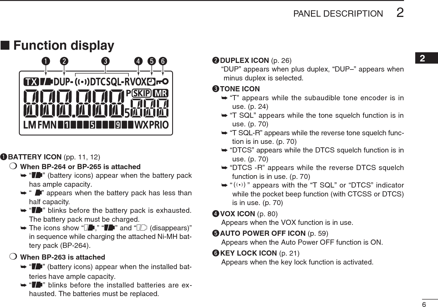
![8013OPTIONS12345678910111213141516171819The transceiver has a VOX function, which allows hands-free operation.An optional HS-94, HS-95 or HS-97 headset and the OPC-2006 plug adapter cable are also required for operation.• The VOX (voice operated transmission) function starts transmis-sion when you speak into the microphone, without needing to push [PTT]; then, automatically returns to reception when you stop speaking.DOptional unit connectionq Push and hold [ ] for 1 sec. to turn the power OFF.w Remove the jack cover.e Connect the optional HS-94, HS-95 or HS-97 and OPC-2006, as illustrated below.OPC-2006HS-95TransceiverDTurning the VOX function ON or OFFq Connect an optional headset and plug adapter cable to the transceiver, and then turn the power ON.w Push [SET] to enter the Set mode.e Rotate [DIAL] to select the VOX setting item, then rotate [VOL] to select “On.”rPush [V/M/C] to return to the frequency display.•“VOX” appears when the VOX function is ON.NOTE: • When using the VOX function, adjust the microphone gain and the VOX-related settings (p. 81) to suit your operating environment (including your headset performance).• Set the microphone gain before setting the VOX gain in the Set mode (p. 58). We recommend setting the micro-phone gain to 3.• When the PTT lock is set to “On” in the Set mode, you cannot transmit using the VOX function. (p. 62)N VOX function](https://usermanual.wiki/ICOM-orporated/325300/User-Guide-1227495-Page-87.png)
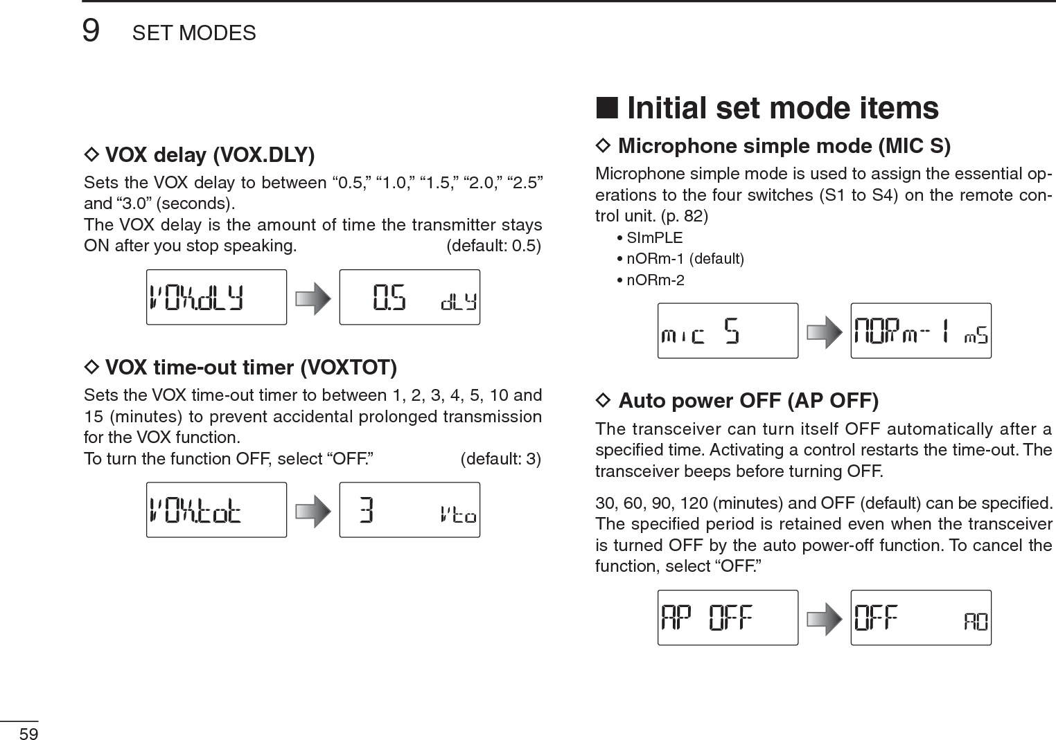
![8113 OPTIONSDVOX-related settingsThe VOX gain, the VOX delay, and the VOX time-out timer can be set in the Set mode.q Connect an optional headset and plug adapter cable to the transceiver, and then turn the power ON.w Push [SET] to enter the Set mode.e Rotate [DIAL] to select the VOX gain (VOX LV), the VOX delay (VOX.dLy), or the VOX time-out timer (VOX.tot) item.r Rotate [VOL] to select a desired option.tPush [V/M/C] to exit the Set mode.The VOX function does not activate transmission while in the Set mode.•VOX gainThe VOX gain level can be adjusted between 1 (minimum) and 10 (maximum), or turned OFF. Higher values make the VOX function more sensitive to your voice. (default: 5)±While speaking into the headset microphone, adjust the VOX gain until “VOX” continuously appears on the LCD.If “VOX” is intermittent, be sure the VOX delay is set long enough to allow normal pauses in speech, but keep the VOX ON until you finish speaking. CONVENIENT!While transmitting using the VOX function, you can adjust the VOX gain simply by rotating [DIAL].•VOX delaySets the VOX delay to between 0.5 and 3.0 seconds (in 0.5 sec. steps). The VOX delay is the amount of time the transmit-ter stays ON after you stop speaking. (default: 0.5)•VOX time-out timerSets the VOX time-out timer to between 1, 2, 3, 4, 5, 10 and 15 minutes to prevent accidental prolonged transmission for the VOX function.To turn the function OFF, select “OFF.” (default: 3)](https://usermanual.wiki/ICOM-orporated/325300/User-Guide-1227495-Page-88.png)
![8213OPTIONS12345678910111213141516171819N Remote control functionThe remote control unit allows you to remotely select operat-ing frequencies, memory channels, etc.•User remote control unitThe below circuit is for reference only.2.7k:6.8k:15k:33k:+–S1 S2 S3 S4to the [SP] jackGNDSPREMOTERated input 700 mW (8 :)EXTERNAL SPEAKER3.5(d) mm>ĴBe sure to turn power OFF when plugging/unplugging the remote control unit to/from the [SP/MIC] jack.D Simple remote control modeq While continuing to push [SET], turn the power ON to enter the Initial set mode.w Rotate [DIAL] to select the microphone simple mode (mic S) item.e Rotate [DIAL] to select “SImPLE,” “nORm-1” or “nORm-2” option.r Push [ ] to return to the frequency display.• SIMPLES1 Selects the Call channel.S2 Turns the monitor function ON or OFF.S3 Selects memory channel 0.S4 Selects memory channel 1.• NORM-1S1 Toggles the VFO mode and the memory mode.S2 Selects the Call channel.S3 Frequency or memory channel “UP.”S4 Frequency or memory channel “DOWN.”• NORM-2S1 Toggles the VFO mode and the memory mode.S2 Turns the monitor function ON or OFF.S3 Frequency or memory channel “UP.”S4 Frequency or memory channel “DOWN.”The VFO mode cannot be selected via the remote control unit when SIMPLE mode is selected.• COMMON (SIMPLE/NORM-1/NORM-2)S2 Transmits T-CALL (1750 Hz tone) while pushing [PTT].S3 Volume “UP” while operating the monitor function.S4 Volume “DOWN” while operating the monitor function.](https://usermanual.wiki/ICOM-orporated/325300/User-Guide-1227495-Page-89.png)