ICOM orporated 325300 VHF/UHF Dual Band FM Transceiver User Manual
ICOM Incorporated VHF/UHF Dual Band FM Transceiver
Users Manual

This device complies with Part 15 of the FCC Rules. Operation is
subject to the following two conditions: (1) this device may not cause
harmful interference, and (2) this device must accept any interference
received, including interference that may cause undesired operation.
WARNING: MODIFICATION OF THIS DEVICE TO RECEIVE CEL-
LULAR RADIOTELEPHONE SERVICE SIGNALS IS PROHIBITED
UNDER FCC RULES AND FEDERAL LAW.
INSTRUCTION MANUAL
iT70A
iT70
E
VHF/UHF DUAL BAND FM TRANSCEIVER

i
FOREWORD
Thank you for purchasing this fine Icom product. The IC-
T70A/T70E VHF
/
UHF DUAL BAND FM TRANSCEIVER is designed
and build with Icom’s superior technology and craftsmanship.
With proper care, this product should provide you with years
of trouble-free operation.
We want to take a moment of your time to thank you for mak-
ing your IC-T70A/T70E your radio of choice, and hope you
agree with Icom’s philosophy of “technology first.” Many hours
or research and development went into the design of your
IC-T70A/T70E.
EXPLICIT DEFINITIONS
WORD DEFINITION
R DANGER! Personal death, serious injury or an ex-
plosion may occur.
R WARNING! Personal injury, fire hazard or electric
shock may occur.
CAUTION Equipment damage may occur.
NOTE Recommended for optimum use. No risk
of personal injury, fire or electric shock.
FEATURES
MDust-protection/Splash-resistant construc-
tion (IP54*)
*Only when the battery pack/case, antenna and jack cover
are attached.
MBuilt in VOX circuit enabling the VOX opera-
tion* (voice operated transmission)
*To use the VOX operation, an optional headset and a plug
adapter cable are additionally required.
M700 mW* AF power with BTL (bridge-tied
load) amplifier
*At 10% distortion with a 16 : load
IMPORTANT
READ ALL INSTRUCTIONS carefully and completely
before using the transceiver.
SAVE THIS INSTRUCTION MANUAL— This
instruction manual contains important operating instructions
for the IC-T70A/T70E.

ii
RWARNING RF EXPOSURE! This device emits
Radio Frequency (RF) energy. Caution should be observed
when operating this device. If you have any questions regard-
ing RF exposure and safety standards please refer to the
Federal Communications Commission Office of Engineering
and Technology’s report on Evaluating Compliance with FCC
Guidelines for Human Radio Frequency Electromagnetic
Fields (OET Bulletin 65)
RWARNING! NEVER hold the transceiver so that
the antenna is very close to, or touching exposed parts of
the body, especially the face or eyes, while transmitting. The
transceiver will perform best if the microphone is 5 to 10 cm
(2 to 4 inches) away from the lips and the transceiver is verti-
cal.
RWARNING! NEVER operate the transceiver with
an earphone, headphones or other audio accessories at high
volume levels. Hearing experts advise against continuous
high volume operation. If you experience a ringing in your
ears, reduce the volume level or discontinue use.
RWARNING! NEVER operate the transceiver while
driving a vehicle. Safe driving requires your full attention—
anything less may result in an accident.
NEVER connect the transceiver to a power source of more
than 16 V DC. This will ruin the transceiver.
NEVER connect the transceiver to a power source using
reverse polarity. This will ruin the transceiver.
DO NOT operate the transceiver near unshielded electri-
cal blasting caps or in an explosive atmosphere.
DO NOT push the PTT unless you actually intend to trans-
mit.
BE CAREFUL! The transceiver will become hot when op-
erating it continuously for long periods.
DO NOT use or place the transceiver in direct sunlight
or in areas with temperatures below –20°C (–4˚F) or above
+60°C (+140˚F).
Place the unit in a secure place to avoid inadvertent use by
children.
DO NOT use harsh solvents such as benzine or alcohol to
clean the transceiver, because they can damage the trans-
ceiver’s surfaces.
PRECAUTIONS

iii
FCC INFORMATION
• FOR CLASS B UNINTENTIONAL RADIATORS:
This equipment has been tested and found to comply with the
limits for a Class B digital device, pursuant to part 15 of the
FCC Rules. These limits are designed to provide reasonable
protection against harmful interference in a residential instal-
lation. This equipment generates, uses and can radiate radio
frequency energy and, if not installed and used in accordance
with the instructions, may cause harmful interference to radio
communications. However, there is no guarantee that inter-
ference will not occur in a particular installation. If this equip-
ment does cause harmful interference to radio or television
reception, which can be determined by turning the equipment
off and on, the user is encouraged to try to correct the inter-
ference by one or more of the following measures:
• Reorient or relocate the receiving antenna.
• Increase the separation between the equipment and re-
ceiver.
• Connect the equipment into an outlet on a circuit different
from that to which the receiver is connected.
• Consult the dealer or an experienced radio/TV technician
for help.
PRECAUTIONS
KEEP the transceiver away from heavy rain, and never im-
merse it in the water. The transceiver meets IP54* require-
ments for dust-protection and splash resistance. However,
once the transceiver has been dropped, dust-protection and
splash resistance cannot be guaranteed because of possible
damage to the transceiver's case or the waterproof seal.
*Only when the supplied battery pack (or optional battery
pack/case), antenna and jack cover are attached.
NEVER operate or touch the transceiver with wet hands.
This may result in an electric shock or may damage the trans-
ceiver.
Even when the transceiver power is OFF, a slight current still
flows in the circuits. Remove the battery pack or batteries
from the transceiver when not using it for a long time. Other-
wise, the installed battery pack or batteries will become ex-
hausted, and will need to be recharged or replaced.
CAUTION: Changes or modifications to this device, not
expressly approved by Icom Inc., could void your authority
to operate this device under FCC regulations.
iv
Icom, Icom Inc. and the Icom logo are registered trademarks of Icom
Incorporated (Japan) in Japnan, the United States, the United King-
dom, Germany, France, Spain, Russia and/or other countries.
1
2
3
4
5
6
7
8
9
10
11
12
13
14
15
16
17
18
19
Microsoft, Windows and Windows Vista are registered trademarks of
Microsoft Corporation in the United States and/or other countries.
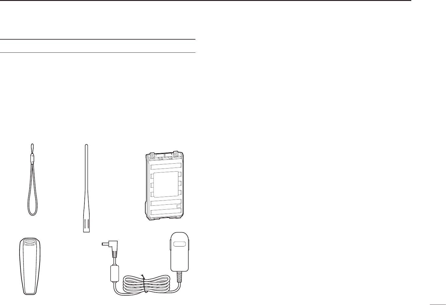
SUPPLIED ACCESSORIES
The following accessories are supplied with the transceiver.
qHand strap ····································································· 1
wAntenna ·········································································· 1
eBattery pack (BP-264)* ·················································· 1
rBelt clip* ··········································································1
tBattery charger (BC-167SA/SD/SV)* ····························· 1
* Not supplied, or the shape is different, depending on the transceiver
version.
t
e
q
r
w

v
FOREWORD ····················································································· i
EXPLICIT DEFINITIONS ··································································· i
FEATURES ························································································ i
IMPORTANT ······················································································ i
PRECAUTIONS ············································································ii, iii
FCC INFORMATION ······································································· iii
SUPPLIED ACCESSORIES ···························································· iv
TABLE OF CONTENTS ·······························································v, vi
1 ACCESSORY ATTACHMENT·················································1–2
N Hand strap ···············································································1
N Belt clip ····················································································1
N Battery pack ·············································································2
N Antenna ···················································································2
2 PANEL DESCRIPTION ···························································3–8
N Front, top and side panels ·······················································3
N Function display ·······································································6
3 BATTERY CHARGING ·························································8–15
N Caution (for the supplied BP-264 Ni-MH battery pack) ············8
N Caution (for the optional BP-265 Li-Ion battery pack) ··············9
N Optional battery case ·····························································11
N Battery information ································································11
N Regular charging ···································································12
N Rapid charging with the BC-191 ············································13
N Rapid charging with the BC-193 ············································14
N External DC power operation ·················································15
4 BASIC OPERATION ···························································16–23
N Power ON ··············································································16
N Setting audio volume ·····························································16
N Setting squelch level ······························································17
N Monitor function ·····································································17
N Setting the mode····································································18
N Setting a tuning step ······························································19
N Setting a frequency ································································19
N Operating mode selection ······················································21
N Key lock function ····································································21
N Receiving ···············································································22
N Transmit power selection ·······················································22
N Transmitting ············································································23
5 REPEATER AND DUPLEX OPERATIONS ························24–28
N Repeater operation ································································24
N Duplex operation ····································································26
N Reverse duplex function ························································26
N Auto repeater function ···························································27
N 1750 Hz tone ·········································································28
6 MEMORY/CALL CHANNELS ···············································29–39
N General description································································29
N Selecting a call channel ·························································29
N Selecting a memory channel ·················································30
N Memory channel programming ··············································31
N Memory bank setting ·····························································32
N Memory bank selection ··························································33
N Programming memory/bank/scan name ································34
TABLE OF CONTENTS

vi
N Selecting memory/bank name indication ·······························35
N Display type ···········································································36
N Copying memory/call contents···············································37
N Memory clearing ····································································38
N Erasing/transferring bank contents ········································39
7 SCAN OPERATION ····························································40–47
N Scan types ·············································································40
N Full/band/programmed scan ·················································42
N Scan edges programming ······················································43
N Memory scan ········································································44
N Memory bank scan ································································45
N Skip channel/frequency setting ··············································46
N Scan resume condition ··························································47
8 PRIORITY WATCH······························································48–50
N Priority watch types ·······························································48
N Priority watch operation ·························································49
9 SET MODES ········································································51–64
N General ··············································································51
N Set mode item list ··································································52
N Initial set mode item list ·························································52
N Set mode items ······································································53
N Initial set mode items ·····························································59
10 OTHER FUNCTIONS ··························································65–75
N Programming a DTMF code sequence ··································65
N Transmitting a DTMF code sequence ····································66
N Setting DTMF transfer speed ·················································67
N Tone frequency and DTCS code ············································68
NTone/DTCS squelch ·······························································70
N Tone scan···············································································71
N Weather channel operation ····················································72
N Cloning function ·····································································74
N Resetting················································································75
11 TROUBLESHOOTING·······························································76
12 SPECIFICATIONS·····································································77
13 OPTIONS ············································································78–82
N VOX function ··········································································80
N Remote control function ·························································82
14 CE ····················································································· 83, 84
INDEX ·····················································································85–88
TABLE OF CONTENTS 1
2
3
4
5
6
7
8
9
10
11
12
13
14
15
16
17
18
19
1
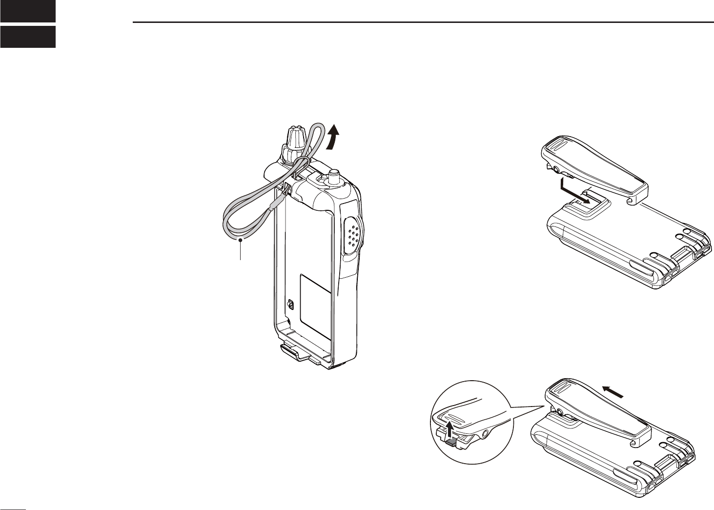
ACCESSORY ATTACHMENT
1
N Hand strap
To facilitate carrying the
transceiver, slide the hand
strap through the loop on
the top of the rear panel as
illustrated at right.
N Belt clip
To attach the belt clip:
Slide the belt clip in the
direction of the arrow
until the belt clip locks in
place, and makes a ‘click’
sound.
To detach the belt clip:
qRemove the battery pack from the transceiver, if it is at-
tached. (p. 2)
wLift the tab up (q), and slide the belt clip in the direction
of the arrow (w).
qw
Handstrap
2
1
ACCESSORY ATTACHMENT
1
2
3
4
5
6
7
8
9
10
11
12
13
14
15
16
17
18
19
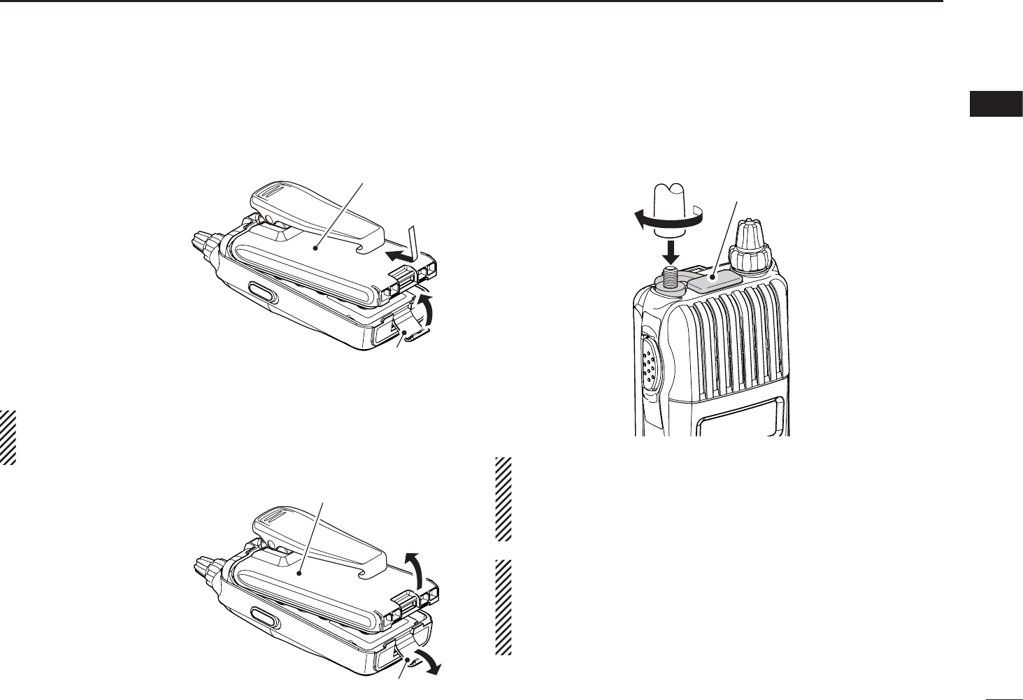
N Battery pack
To attach the battery pack:
qFit the battery pack
in the direction of the
arrow (q), then close.
wHook the latch until it
makes a ‘click’ sound
(w).
• Charge the battery pack
before use. (pp. 12–14)
To detach the battery pack:
Be careful! The latch is tightly locked, so use caution
when releasing it. DO NOT use your finger nail. Use the
edge of a coin or screwdriver tip to carefully release it.
Unhook the latch (e),
and lift up the battery
pack in the direction of
the arrow (r).
N Antenna
Insert the antenna connector into the antenna and tighten the
antenna screw.
Jack cover
•NEVER carry the transceiver by holding only the an-
tenna.
•When the jack is not in use, keep the jack cover attached
to protect the connector from dust and moisture.
For your information
Third-party antennas may increase transceiver
performance. An optional AD-92SMA ANTENNA
CONNECTOR ADAPTER is available to connect an antenna
that has a BNC connector.
w
q
Latch
Battery pack/Battery case
e
r
Latch
Battery pack/Battery case
3
PANEL DESCRIPTION
2
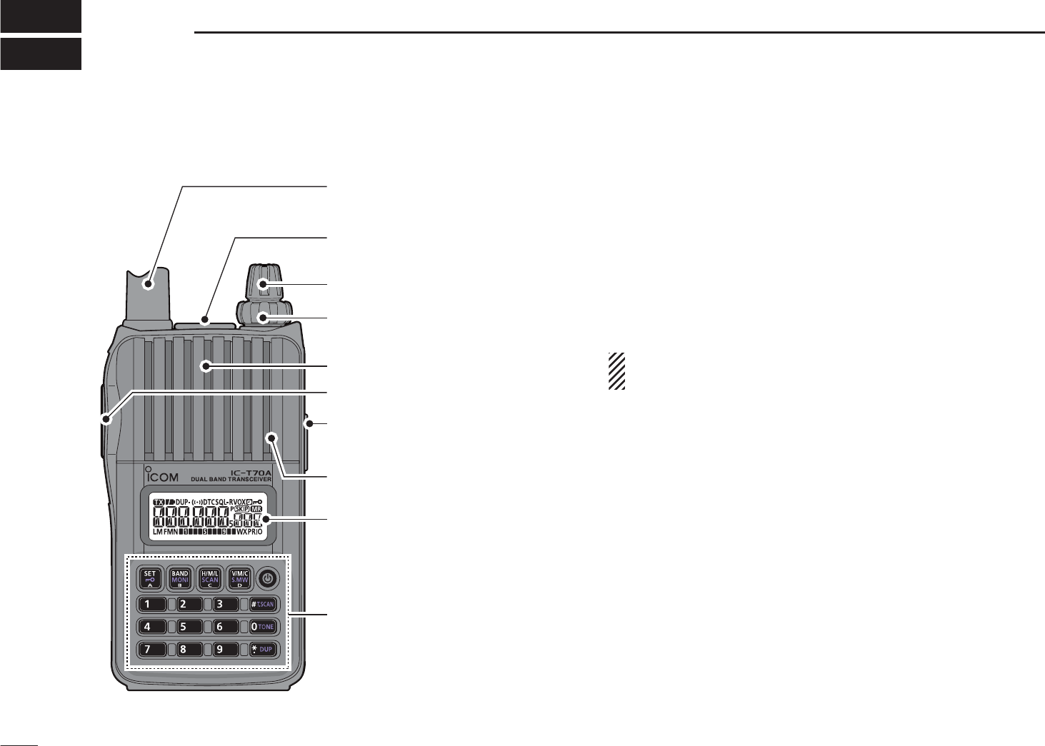
N Front, top and side panels
Speaker
ANTENNA
CONNECTOR
EXTERNAL
DC IN JACK
VOLUME
CONTROL
CONTROL DIAL
EXTERNAL SPEAKER/
MICROPHONE JACKS
Keypad (pp. 4, 5)
Internal microphone
Function display (pp. 6, 7)
PTT SWITCH
e
r
y
w
q
t
qANTENNA CONNECTOR (p. 3)
Connects the supplied antenna.
• An optional AD-92SMA adapter (p. 79) is available for connect-
ing an antenna with a BNC connector.
wEXTERNAL SPEAKER/MICROPHONE JACKS [SP/MIC]
Connect an optional speaker microphone, cloning cable,
or headset, if desired.
See page 79 for a list of available options.
Be sure to turn power OFF before connecting or dis-
connecting optional equipment to/from the [SP/MIC]
jack.
eCONTROL DIAL [DIAL]
± Rotate to tune the operating frequency. (p. 19)
±During memory mode, rotate to select the memory
channel. (pp. 18, 30)
±While scanning, changes the scanning direction.
(pp. 42, 44, 45)
±While continuing to push [MONI](BAND), sets the
squelch level. (p. 17)
±After pushing [BAND] during memory mode operation,
selects the programmed bank. (p. 33)
±During set mode operation, rotate to select the set
items. (p. 51)
4
2
PANEL DESCRIPTION
1
2
3
4
5
6
7
8
9
10
11
12
13
14
15
16
17
18
19
rVOLUME CONTROL [VOL]
±Adjust audio volume level. (p. 16)
±During set mode operation, rotate to select the options.
(p. 51)
tPTT SWITCH [PTT]
±Push and hold to transmit, release to receive. (p. 23)
For IC-T70E only
±Push briefly, then push and hold to transmit a 1750 Hz
tone burst. (p. 28)
yEXTERNAL DC IN JACK [DC IN]
±Connects the supplied wall charger, BC-167S, to charge
the attached battery pack, BP-264. (p. 12)
• The transceiver can charge only the Ni-MH battery pack, BP-
264. Charging the Li-Ion battery pack, BP-265 requires the
rapid charger, BC-193.
±Connect an external DC power supply through the op-
tional CP-12L, CP-19R or OPC-254L for external DC
operation. (p. 15)
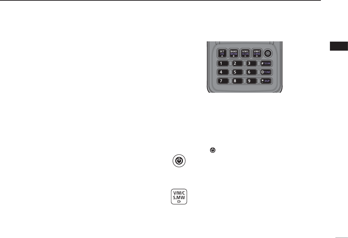
D Keypad
±Push to input numeral for frequency input, memory chan-
nel selection.
±Push to send the DTMF code. (pp. 66, 67)
• [0]–[9] send “0”–“9,” [A](SET) sends “A,” [B](BAND) sends “B,”
[C](H/M/L) sends “C,” [D](V/M/C) sends “D,” [1](DUP) sends
“1(E)” and [#](T.SCAN) sends “# (F).”
POWER KEY [ ]
±Push and hold for 1 sec. to turn the transceiver
power ON or OFF. (p. 16)
VFO/MEMORY/CALL • SELECT MEMORY WRITE KEY
[V/M/C] • [S.MW](V/M/C)
±Push to select the VFO mode, memory mode, call
channel mode or weather channel mode*. (pp. 18,
29, 30, 72)
*Only for the U.S.A. version transceiver.
±Push and hold for 1 sec. to enter select memory
write mode. (p. 31)

5
2PANEL DESCRIPTION
DKeypad (continued)
BAND • MONITOR KEY [BAND] • [MONI](BAND)
±During VFO mode operation, push to select an
operating frequency band. (p. 19)
±Push and hold to open the squelch temporarily
and monitor the operating frequency. (p. 17)
±While continuing to push this key, rotate [DIAL] to
adjust the squelch level. (p. 17)
±During memory mode operation, push to enter the
memory bank group selection. (p. 33)
OUTPUT POWER • SCAN KEY [H/M/L] • [SCAN](H/M/L)
±Push to select the output power. (p. 22)
• Selects the transmit output power from high, mid or
low.
±Push and hold for 1 sec. to enter the scan type
selection mode. (pp. 42, 44, 45)
• Push again to start the scan.
SET • LOCK KEY [SET] • [ ](SET)
±Push to enter the Set mode. (p. 51)
±Push and hold for 1 sec. to toggle the lock func-
tion ON or OFF. (p. 21)
±During select memory write mode, push to select
the items. (pp. 32, 34, 38, 39)
TONE SCAN [T.SCAN](#)
±Push and hold for 1 sec. to start tone scan func-
tion. (p. 71)
TONE/TONE SQUELCH KEY [TONE](0)
±Push and hold for 1 sec. to select repeater tone,
tone squelch, tone squelch reverse, DTCS
squelch, DTCS squelch reverse and no tone op-
eration in sequence. (p. 70)
• Pocket beep function is available for tone squelch and
DTCS squelch. (p. 70)
DUPLEX KEY [DUP](1)
±Push and hold for 1 sec. to select minus duplex,
plus duplex or simplex operation. (p. 26)
• “DUP–” (minus duplex), “DUP” (plus duplex) and no
indication (simplex) appear in order.
6
2
PANEL DESCRIPTION
1
2
3
4
5
6
7
8
9
10
11
12
13
14
15
16
17
18
19
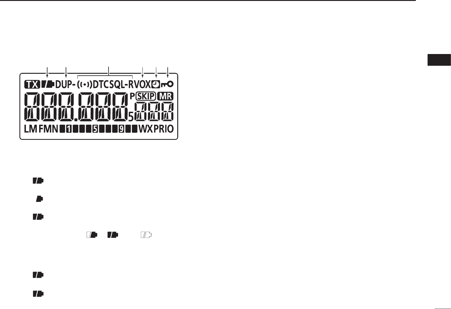
N Function display
ytrq we
qBATTERY ICON (pp. 11, 12)
MWhen BP-264 or BP-265 is attached
±“” (battery icons) appear when the battery pack
has ample capacity.
±“” appears when the battery pack has less than
half capacity.
±“” blinks before the battery pack is exhausted.
The battery pack must be charged.
±The icons show “ ,” “ ” and “ (disappears)”
in sequence while charging the attached Ni-MH bat-
tery pack (BP-264).
MWhen BP-263 is attached
±“” (battery icons) appear when the installed bat-
teries have ample capacity.
±“” blinks before the installed batteries are ex-
hausted. The batteries must be replaced.
wDUPLEX ICON (p. 26)
“DUP” appears when plus duplex, “DUP–” appears when
minus duplex is selected.
eTONE ICON
± “T” appears while the subaudible tone encoder is in
use. (p. 24)
± “T SQL” appears while the tone squelch function is in
use. (p. 70)
± “T SQL-R” appears while the reverse tone squelch func-
tion is in use. (p. 70)
± “DTCS” appears while the DTCS squelch function is in
use. (p. 70)
± “DTCS -R” appears while the reverse DTCS squelch
function is in use. (p. 70)
± “S” appears with the “T SQL” or “DTCS” indicator
while the pocket beep function (with CTCSS or DTCS)
is in use. (p. 70)
r VOX ICON (p. 80)
Appears when the VOX function is in use.
t AUTO POWER OFF ICON (p. 59)
Appears when the Auto Power OFF function is ON.
yKEY LOCK ICON (p. 21)
Appears when the key lock function is activated.
7
2PANEL DESCRIPTION
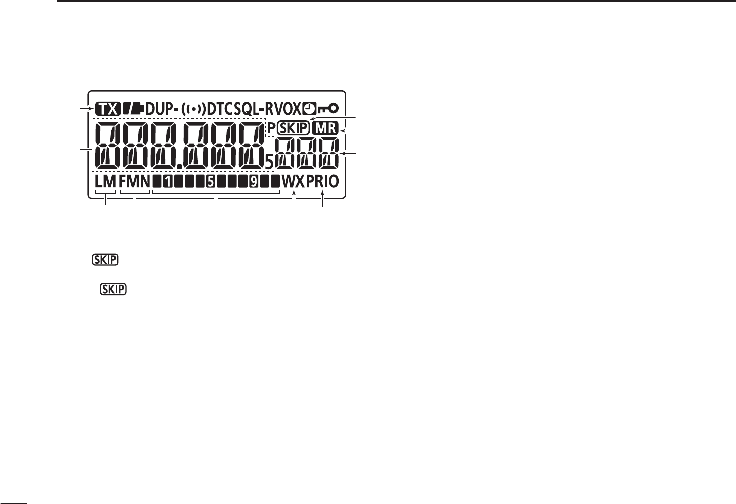
NFunction display (continued)
!4 !3 !2
i
o
u
!5
!6
!1 !0
uSKIP ICONS
±“ ” appears when the selected memory channel is
set as a skip channel. (p. 46)
±“P” appears when the displayed frequency is set
as a skip frequency in memory mode. (p. 46)
iMEMORY ICON (pp. 18, 30)
Appears when memory mode is selected.
oMEMORY CHANNEL NUMBER
±Shows the selected memory channel number.
(pp. 18, 30)
±“C0” or “C1” appears when the call channel is selected.
(pp. 18, 29)
!0PRIORITY WATCH ICON (pp. 49, 50)
Appears when priority watch is in use.
!1WEATHER CHANNEL ICON (pp. 72–73)
Appears when the weather alert function is in use.
!2S/RF METER
±Shows the relative signal strength while receiving sig-
nals. (p. 22)
±Shows the output power level while transmitting.
(pp. 22, 23)
!3OPERATING MODE ICONS (p. 21)
Shows the selected operating mode.
• FM and FMN are selectable.
!4POWER ICONS (p. 22)
± “L” appears when low power is selected.
± “M” appears when middle power is selected.
± No indicator appears when high power is selected.
!5FREQUENCY READOUT
±Displays a variety of information, such as operating fre-
quency, set mode contents.
• The decimal point blinks during scan.
±During memory mode operation, the programmed
memory or memory bank name is displayed.
!6TRANSMIT ICON (p. 23)
Appears during transmit.

8
3
BATTERY CHARGING
1
2
3
4
5
6
7
8
9
10
11
12
13
14
15
16
17
18
19
•
R DANGER! NEVER short terminals (or charging terminals)
of the battery pack. Also, current may flow into nearby metal
objects such as a necklace, so be careful when placing bat-
tery packs (or the transceiver) in handbags, etc.
Simply carrying with or placing near metal objects such as
a necklace, etc. may cause shorting. This may damage not
only the battery pack, but also the transceiver.
•R DANGER! NEVER incinerate used battery packs. Inter-
nal battery gas may cause an explosion.
•R DANGER! NEVER immerse the battery pack in water.
If the battery pack becomes wet, be sure to wipe it dry BE-
FORE attaching it to the transceiver.
•CAUTION: Always use the battery within the specified tem-
perature range, –5˚C to +60˚C (+23˚F to +140˚F). Using
the battery out of its specified temperature range will re-
duce the battery’s performance and battery life.
•CAUTION: Shorter battery life could occur if the battery is
left completely discharged, or in an excessive temperature
environment (above +55˚C; +131˚F) for an extended period
of time. If the battery must be left unused for a long time,
it must be detached from the radio after charging. Keep it
safely in a cool dry place at the following temperature range:
–20˚C to +45˚C (–4˚F to +113˚F) (up to a month)
–20˚C to +35˚C (–4˚F to +95˚F) (up to six months)
–20˚C to +25˚C (–4˚F to +77˚F) (up to a year*)
* We recommend charging the battery pack every 6 months.
•Clean the battery terminals to avoid rust or misscontact.
•Keep battery terminals clean. It’s a good idea to clean bat-
tery terminals once a week.
• If your Ni-MH battery pack seems to have no capacity, even
after being charged, completely discharge it by leaving the
power ON overnight. Then, fully charge the battery pack again.
If the battery pack still does not retain a charge (or only very lit-
tle charge), a new battery pack must be purchased.
Prior to using the transceiver for the first time, the battery
pack must be fully charged for optimum life and operation.
• Recommended temperature range for charging:
between 0°C and +45°C for the regular charge by the
transceiver.
or between +10°C and +40°C for the rapid charge with the
BP-191.
• Use the supplied charger (BC-167S) or optional charger
(BC-191) only. NEVER use other manufacturers’ chargers.
• The battery pack contains a rechargeble battery.
Charge the battery pack before first operating the trans-
ceiver, or when the battery pack becomes exhausted.
If you want to prolong the battery life, the following points
should be observed:
- Avoid over charging.
- Use the battery pack until it becomes almost completely
exhausted, under normal conditions. We recommend bat-
tery charging after transmitting becomes impossible.
N Caution (for the supplied BP-264 Ni-MH battery pack)

9
3BATTERY CHARGING
N Caution (for the optional BP-265 Li-Ion battery pack)
•R DANGER! Use and charge only specified Icom battery
packs with Icom radios and Icom chargers. Only Icom bat-
tery packs are tested and approved for use with Icom radios
or charged with Icom chargers. Using third-party or coun-
terfeit battery packs may cause smoke, fire, or cause the
battery to burst.
D Battery caution
•R DANGER! DO NOT hammer or otherwise impact the bat-
tery. Do not use the battery if it has been severely impacted
or dropped, or if the battery has been subjected to heavy
pressure. Battery damage may not be visible on the outside
of the case. Even if the surface of the battery does not show
cracks or any other damage, the cells inside the battery may
rupture or catch fire.
•R DANGER! NEVER use or leave battery pack in areas
with temperatures above +60˚C (+140˚F). High tempera-
ture buildup in the battery, such as could occur near fires
or stoves, inside a sun heated car, or in direct sunlight may
cause the battery to rupture or catch fire. Excessive tem-
peratures may also degrade battery performance or shorten
battery life.
•R DANGER! DO NOT expose the battery to rain, snow,
seawater, or any other liquids. Do not charge or use a wet
battery. If the battery gets wet, be sure to wipe it dry before
using.
•R DANGER! NEVER incinerate a used battery pack, since
internal battery gas may cause it to rupture, or may cause
an explosion.
•R DANGER! NEVER solder the battery terminals, or
NEVER modify the battery pack. This may cause heat gen-
eration, and the battery may burst, emit smoke or catch
fire.
•R DANGER! Use the battery only with the transceiver for
which it is specified. Never use a battery with any other
equipment, or for any purpose that is not specified in this
instruction manual.
•R DANGER! If fluid from inside the battery gets in your
eyes, blindness can result. Rinse your eyes with clean water,
without rubbing them, and see a doctor immediately.
•R WARNING! Immediately stop using the battery if it emits
an abnormal odor, heats up, or is discolored or deformed. If
any of these conditions occur, contact your Icom dealer or
distributor.
•RWARNING! Immediately wash, using clean water, any
part of the body that comes into contact with fluid from in-
side the battery.
Misuse of Lithium-Ion batteries may result in the following
hazards: smoke, fire, or the battery may rupture. Misuse
can also cause damage to the battery or degradation of
battery performance.

10
3
BATTERY CHARGING
1
2
3
4
5
6
7
8
9
10
11
12
13
14
15
16
17
18
19
• R WARNING! NEVER put the battery in a microwave oven,
high-pressure container, or in an induction heating cooker.
This could cause a fire, overheating, or cause the battery to
rupture.
• CAUTION: Always use the battery within the specified tem-
perature range, –20˚C to +60˚C (–4˚F to +140˚F). Using the
battery out of its specified temperature range will reduce the
battery’s performance and battery life.
• CAUTION: Shorter battery life could occur if the battery is
left fully charged, completely discharged, or in an excessive
temperature environment (above +50˚C; +122˚F) for an ex-
tended period of time. If the battery must be left unused for a
long time, it must be detached from the radio after discharg-
ing. You may use the battery until the remaining capacity is
about half, and then keep it safely in a cool dry place at the
following temperature range:
–20˚C to +50˚C (–4˚F to +122˚F) (up to a month)
–20˚C to +35˚C (–4˚F to +95˚F) (up to three months)
–20˚C to +20˚C (–4˚F to +68˚F) (up to a year)
D Charging caution
• R DANGER! NEVER charge the battery pack in areas with
extremely high temperatures, such as near fires or stoves,
inside a sun-heated vehicle, or in direct sunlight. In such
environments, the safety/protection circuit in the battery will
activate, causing the battery to stop charging.
• R WARNING! DO NOT charge or leave the battery in the
battery charger beyond the specified time for charging. If
the battery is not completely charged by the specified time,
stop charging and remove the battery from the battery char-
ger. Continuing to charge the battery beyond the specified
time limit may cause a fire, overheating, or the battery may
rupture.
• R WARNING! NEVER insert the transceiver (battery at-
tached to the transceiver) into the charger if it is wet or
soiled. This could corrode the battery charger terminals or
damage the charger. The charger is not waterproof.
• CAUTION: DO NOT charge the battery outside of the speci-
fied temperature range: BC-193 (+10˚C to +40˚C; +50˚F to
+104˚F). Icom recommends charging the battery at +20˚C
(+68˚F). The battery may heat up or rupture if charged out
of the specified temperature range. Additionally, battery per-
formance or battery life may be reduced.
11
3BATTERY CHARGING
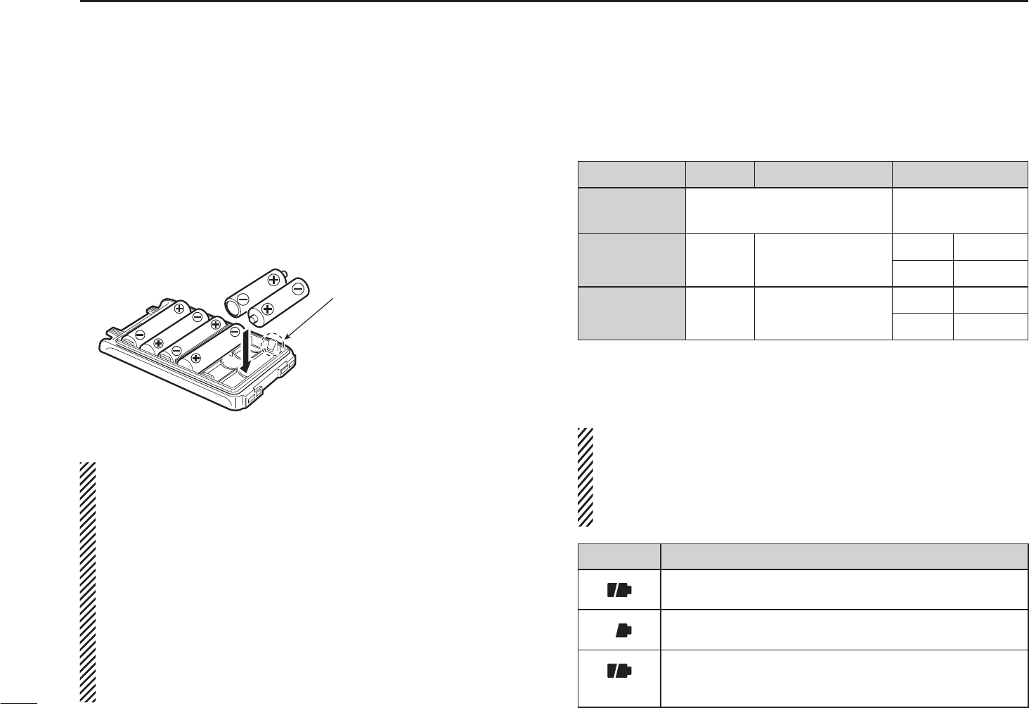
N
Optional battery case (BP-263)
When you would like to use the optional battery case (BP-263),
install 6 uAA (LR6) size alkaline batteries, as shown below.
q Remove the battery case if it is attached. (p. 2)
w Install 6 × AA (LR6) size alkaline batteries.
• Install only alkaline batteries.
• Be sure to observe the correct polarity.
e Attach the battery case. (p. 2)
• When installing batteries, make sure they are all the
same brand, type and capacity. Also, do not mix new
and old batteries together.
• Never use batteries whose insulated covering is damaged.
• Never incinerate used battery cells since internal battery
gas may cause them to rupture.
• Never expose a detached battery case to water. If the bat-
tery case gets wet, be sure to wipe it dry before using it.
• Keep battery contacts clean. It’s a good idea to clean
battery terminals once a week.
• We recommend to select the middle power transmission dur-
ing the battery case operation for protecting batteries heat up.
N Battery information
D Battery life
Battery pack Voltage Capacity Battery life*1
BP-263 Battery case for
AA (LR6) × 6 alkaline —*2
BP-264 7.2 V 1400 mAh (typ.) VHF 11.5 hrs.
UHF 10 hrs.
BP-265 7.4 V 1900 mAh (min.)
2000 mAh (typ.)
VHF 16 hrs.
UHF 13.5 hrs.
*1
When the power save function is set to “Auto,” and the operating
time is calculated under the following conditions;
TX : RX : standby = 5 : 5 : 90
*2The average operating time depends on the alkaline cells used.
Even when the transceiver power is OFF, a small current
still flows in the radio. Remove the battery pack or case
from the transceiver when not using it for a long time. Oth-
erwise, the battery pack or installed batteries will become
exhausted.
Indication Battery condition
The battery pack (BP-264/BP-265) or battery case
(BP-263) has ample capacity.
The battery pack (BP-264/BP-265) is nearing exhaus-
tion.
(blinks)
The battery pack or battery case is exhausted. Charg-
ing (BP-264/BP-265) or replacing batteries (BP-263)
is necessary.
Be careful! The negative
terminals of the battery case
protrude from the body, so
pay attention not to injure
your fingers when inserting
the batteries.
12
3
BATTERY CHARGING
3
N Regular charging
Prior to using the transceiver for the first time, the battery
pack must be fully charged for optimum life and operation.
DBattery icons
The icons show “ ,” “ ” and “ (disappers)” in se-
quence and “CHARGE” appears while charging (when the
transceiver’s power is OFF). The icons and “CHARGE” dis-
appear when the battery pack is completely charged.
DCharging note
• Be sure to turn the transceiver power OFF.
Otherwise the battery pack will not be charged completely
or will take much longer to charge.
• The transceiver can charge only the BP-264 battery pack.
Other types of rechargeable battery, Ni-Cd or Li-Ion batter-
ies cannot be charged.
• External DC power operation becomes possible when using
an optional CP-12L, CP-19R or OPC-254L. The attached
battery pack is also charged simultaneously, except during
transmit (see p. 15 for more details).
• The external DC power supply voltage must be between
10–16 V to charge the battery pack and for operation when
using an optional OPC-254L. (We recommend 11 V DC for
operation.)
• If the battery icons (“ ” and “ ”) disappears only after
1 min. from connecting to the DC power supply, the bat-
tery pack may have problem. In this case, contact your Icom
dealer/distributor, or purchase a new battery pack.
• BC-167S
• CP-12L (Optional)
• OPC-254L (Optional)
to AC outlet
to cigarette lighter
socket (12 V DC)
to 11 V DC
(power supply)
White: +
Black: _
Transceiver
to
[DC IN]
Turn power OFF while
charging the battery
pack.
The shape may
diffe depending
on the version.
• Charging time period:
Approx. 8 hours
BP-264
• CP-19R (Optional)
Be sure to disconnect the AC adapter from the AC outlet
after the battery charging is completed, otherwise the trans-
ceiver may receive switching noise from the AC adapter de-
pending on the operating frequencies and/or antenna used.
13
3BATTERY CHARGING
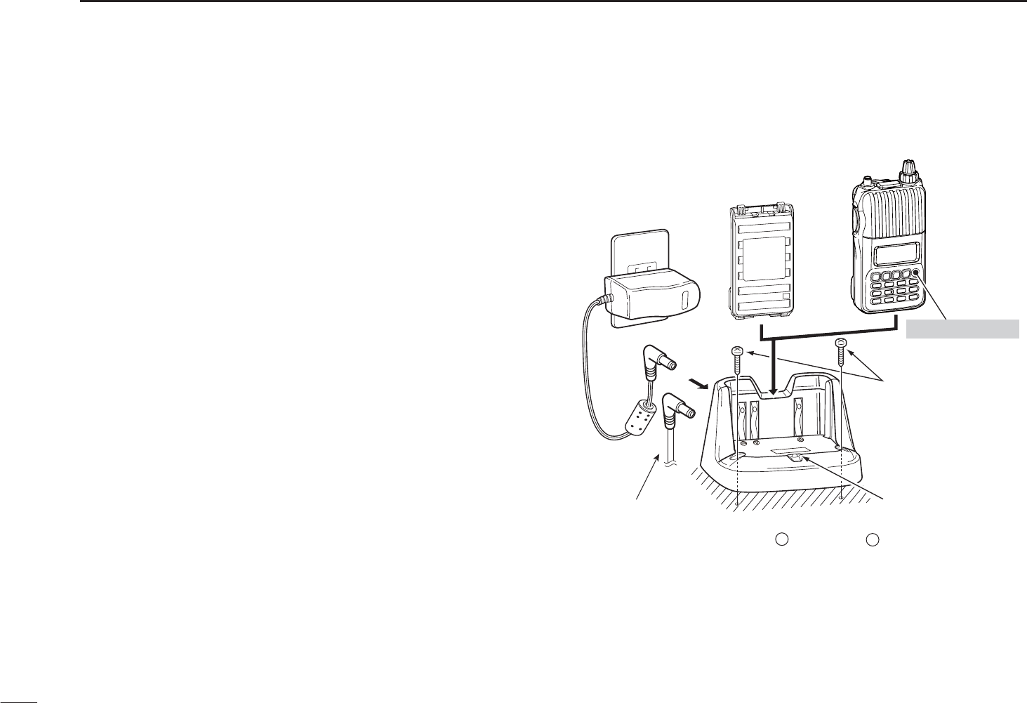
The optional BC-191 provides rapid charging of the Ni-MH
battery pack BP-264.
DCharging note
• Be sure to turn the transceiver power OFF.
• The desktop charger, BC-191, can charge only the BP-264
battery pack. Other types of rechargeable battery, Ni-Cd or
Li-Ion batteries cannot be charged.
•NEVER install the transceiver with battery pack to the BC-
191 when the transceiver is connected to the DC power
supply. This may cause the BC-191’s manufunction and the
charging indicator of the BC-191 lights red. In this case, dis-
connect the AC adapter from the BC-191, and then recon-
nect the AC adapter to the BC-191.
• The optional CP-23L and OPC-515L can be used instead
of the supplied AC adapter. Connect one of these to the
[DC 12-16V] jack in this case.
• Charging period: approx. 2 hours (with BP-264)
TransceiverBattery pack
Charge indicator
• Lights orange :
While charging
• Lights green :
Charging is completed.
• Blinks red :
Charging error occurs.
Screws*
(Self tapping screw:
M3.5 × at least 30 mm)
*Purchase separately.
Using screws is
recommended to
secure the charger.
About OPC-515L
White line: Black line:
CAUTION: NEVER connect the
OPC-515L to a power source
using reverse polarity. This will
ruin the battery charger.
+–
Optional OPC-515L
(for DC power
source) or CP-23L
(for 12 V cigarette
lighter socket) can
be used instead of
the AC adapter.
BC-123S
(supplied
with BC-191)
Turn power OFF
N Rapid charging with the BC-191
14
3
BATTERY CHARGING
3
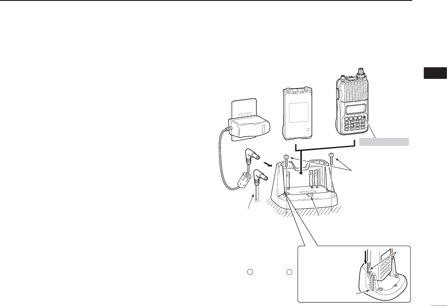
The optional BC-193 provides rapid charging of the Li-Ion-
battery pack BP-265.
DCharging note
• Be sure to turn the transceiver power OFF.
• The desktop charger, BC-193, can charge only the BP-265
battery pack. Other types of rechargeable battery, Ni-Cd or
Ni-MH batteries cannot be charged.
•NEVER install the transceiver with battery pack to the BC-
193 when the transceiver is connected to the DC power
supply. This may cause the BC-193’s manufunction and the
charging indicator of the BC-193 lights red. In this case, dis-
connect the AC adapter from the BC-193, and then recon-
nect the AC adapter to the BC-193.
• The optional CP-23L and OPC-515L can be used instead
of the supplied AC adapter. Connect one of these to the
[DC 12-16V] jack in this case.
• Charging period: approx. 2.5 hours (with BP-265)
Transceiver
Turn power OFF
Battery pack
BC-123S
(supplied
with BC-193)
The optional OPC-
515L (for DC power
source) or CP-23L
(for 12 V cigarette
lighter socket) can
be used instead of
the AC adapter.
Charge indicator
• Lights orange : While charging
• Lights green : Charging is completed.
• Blinks red : Charging error occurs.
Screws*
(Self tapping screw:
M3.5 × at least 30 mm)
*Purchase separately.
Using screws is
recommended to
secure the charger.
About OPC-515L
White line: Black line:
CAUTION: NEVER connect the
OPC-515L to a power source
using reverse polarity. This will
ruin the battery charger.
+–
IMPORTANT!
Ensure the tabs on
the battery pack are
correctly aligned with
the guide rails inside
the charger adapter.
Guide rail
Tabs
N Rapid charging with the BC-193
15
3BATTERY CHARGING
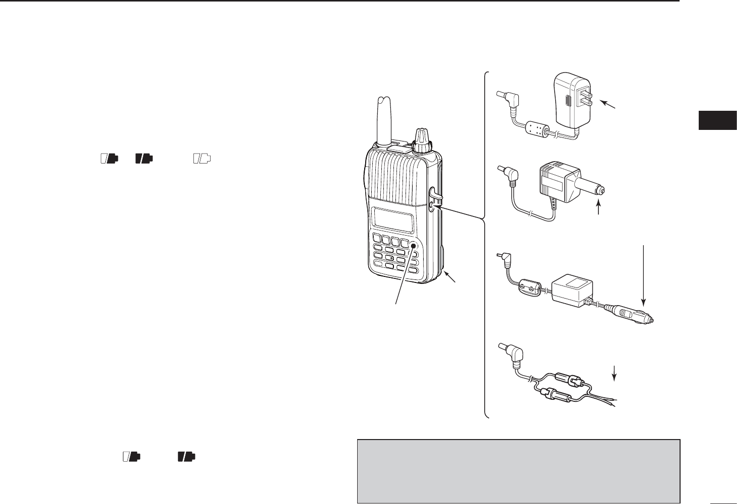
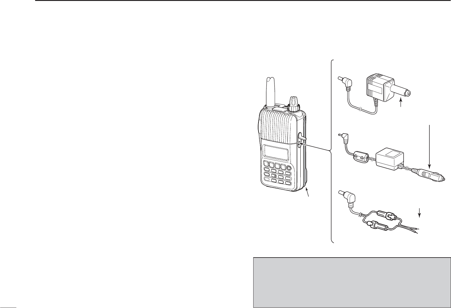
N External DC power operation
An optional cigarette lighter cable (CP-12L or CP-19R; for
12 V cigarette lighter socket) or external DC power cable
(OPC-254L) can be used for external power operation. (We
recommend the CP-19R when you want to connect a 12 V
cigarette lighter socket.)
D Operating note
• Power supply voltage must be between 10.0–16.0 V DC.
(We recommend 11.0 V DC.) NEVER CONNECT OVER 16
V DC directly into the [DC IN] jack of the transceiver.
•BE SURE to use CP-12L, CP-19R or OPC-254L when
connecting a regulated 12 V DC power supply.
Use an external DC-DC converter to connect the transceiver
through optional CP-12L, CP-19R or OPC-254L to a 24 V
DC power source.
• The voltage of the external power supply must be within
10–16 V DC when using either CP-12L, CP-19R or OPC-
254L, otherwise, use the battery pack/battery case.
• Disconnect the power cable from the transceiver when
not using it. Otherwise, the vehicle battery will become ex-
hausted.
• The power save function is deactivated automatically dur-
ing external DC power operation.
Transceiver
BP-264
• CP-12L (Optional)
• CP-19R (Optional)
• OPC-254L (Optional)
to cigarette lighter
socket (12 V DC)
to 11 V DC
(power supply)
White: +
Black: _
to
[DC IN]
NOTE: Up to 5 W (approx.) of maximum output power is
available when using external DC power. However, when
the supplied voltage exceeds 14 V, the built-in protection
circuit activates to reduce the transmit output power to
2.5 W (approx.).
16
4
BASIC OPERATION
1
2
3
4
5
6
7
8
9
10
11
12
13
14
15
16
17
18
19
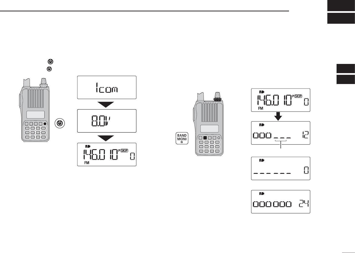
N Power ON
± Push and hold [ ] for 1 sec. to turn power ON.
• Push and hold [ ] for 1 sec. to turn power OFF.
The voltage indication is skipped in the Initial set mode
(p. 61).
N Setting audio volume
± Rotate [VOL]
to adjust the audio level.
• If squelch is closed, push and hold [MONI](BAND) while setting the
audio level.
• The display shows the volume level while setting.
[VOL]
Minimum setting (no audio)
Maximum setting
Volume level
The beep level is adjustable in the Initial set mode (p. 60).
17
4BASIC OPERATION
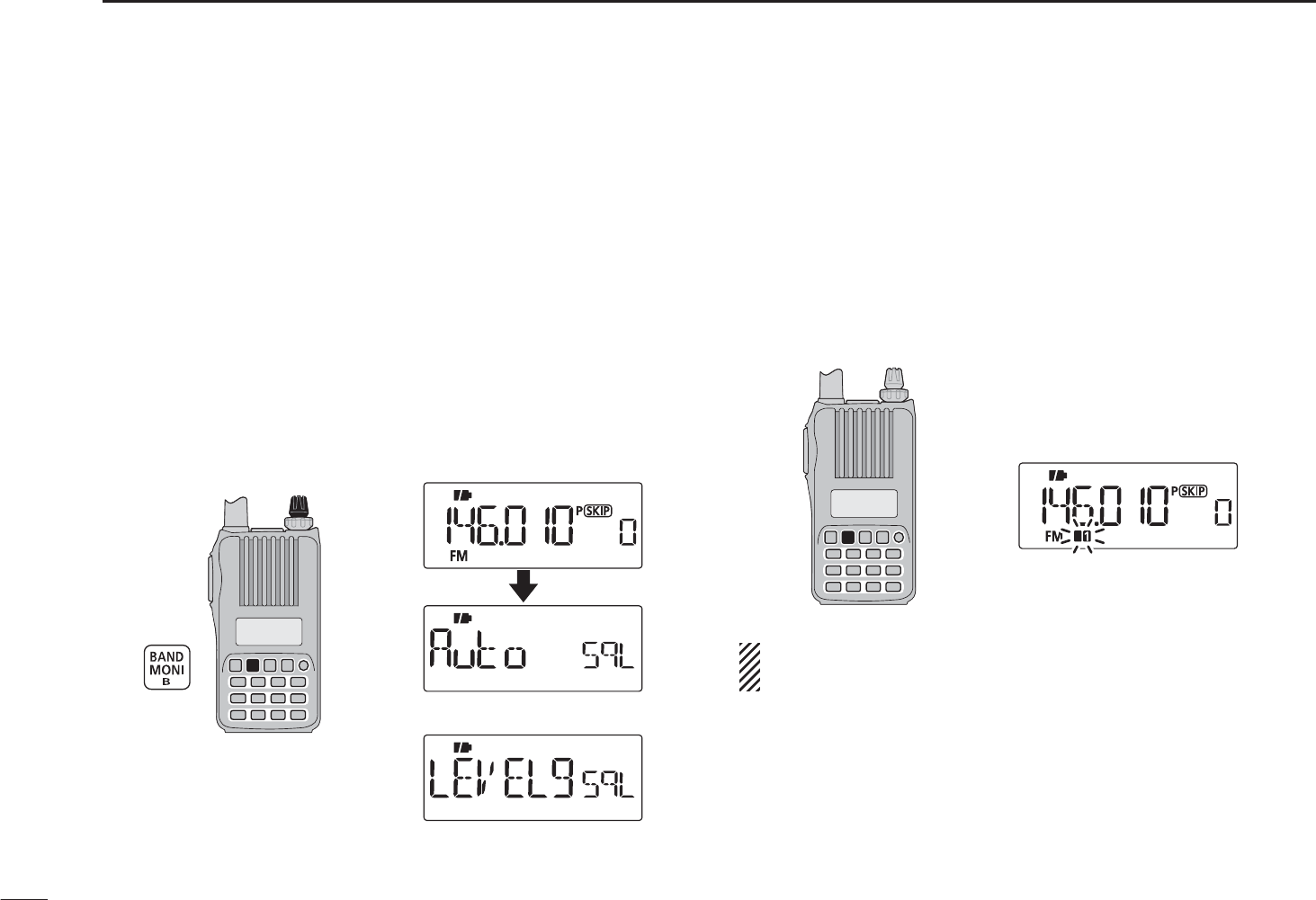
N Setting squelch level
The squelch circuit mutes the received audio signal depend-
ing on the signal strength. The transceiver has 9 squelch lev-
els, a continuously open setting and an automatic squelch
setting.
±While continuing to push [MONI](BAND), rotate [DIAL] to
select the squelch level.
• “LEVEL1” is loose squelch (for weak signals) and “LEVEL9” is
tight squelch (for strong signals).
• “Auto” indicates automatic level adjustment by a noise pulse
counting system.
• “OPEn” indicates continuously open setting.
[DIAL]
Maximum level
Automatic squelch
N Monitor function
This function is used to listen to weak signals without disturb-
ing the squelch setting or to open the squelch manually even
when mute functions such as the tone squelch are in use.
±Push and hold [MONI](BAND) to monitor the operating
frequency.
• The 1st and 2nd segments of the S-meter blink.
Two segments blink
The [MONI] key can be set to ‘sticky’ operation in the Initial
set mode. See page 63 for details.
18
4
BASIC OPERATION
1
2
3
4
5
6
7
8
9
10
11
12
13
14
15
16
17
18
19
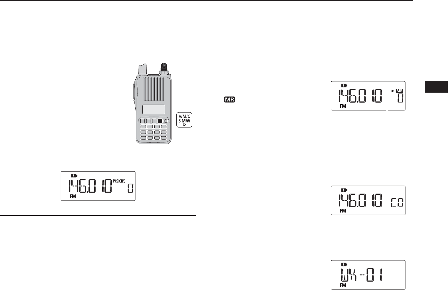
N Setting the mode
q Push [V/M/C] repeatedly to select
the VFO mode, memory mode, call
channel mode or weather channel
mode*, in sequence
*Only for the U.S.A. version transceiver.
w Rotate [DIAL] to change the fre-
quency or select a desired channel.
D VFO mode
The VFO mode is used to set the desired frequency.
• VFO mode display
What is VFO?
VFO is an abbreviation of Variable Frequency Oscillator. Fre-
quencies for both transmitting and receiving are generated
and controlled by the VFO.
D Memory mode
Memory mode is used for opera-
tion on memory channels which
store programmed frequencies.
•“ ” appears when memory mode
is selected.
• Only programmed memory chan-
nels can be selected.
• Enter the memory channel directly to select the desired memory
channel. (p. 30)
D Call channel mode
The Call channel is used for
quick recall of most often-used
frequency.
• “C0” or “C1” appears instead of the
memory channel number when the
Call channel mode is selected.
D Weather channel mode*
There are 10 weather channels
for monitoring weather broad-
casts from NOAA (National
Oceanic and Atmospheric Ad-
ministration).
*Only for the U.S.A. version transceiver.
[DIAL]
• Memory mode display
Appears
• Call channel display
• Weather channel display
19
4BASIC OPERATION
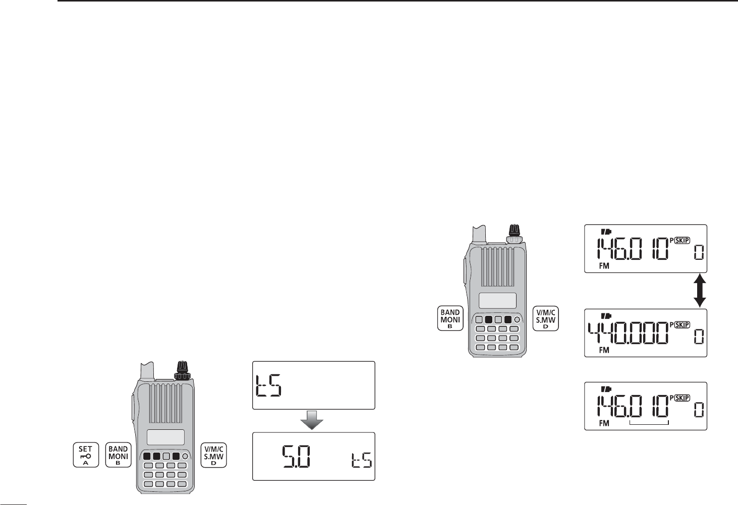
N Setting a tuning step
The tuning step can be selected for both band. The following
tuning steps are available for the IC-T70A/T70E.
• 5.0 kHz • 10.0 kHz • 12.5 kHz • 15.0 kHz
• 20.0 kHz • 25.0 kHz • 30.0 kHz • 50.0 kHz
• 100.0 kHz • 125.0 kHz • 200.0 kHz
D Tuning step selection
q In the VFO mode, push [BAND] to select the desired fre-
quency band.
• If the VFO mode is not selected, such as a memory channel/call
channel mode or the weather channel mode, push [V/M/C] to
select the VFO mode first, then push [BAND] to select the de-
sired band.
w Push [SET] to enter the Set mode.
e Rotate [DIAL] to select the tuning step set item, then ro-
tate [VOL] to select the desired tuning step.
rPush [V/M/C] to return to the VFO mode.
[VOL]
[DIAL]
5 kHz tunin
g
ste
p
N Setting a frequency
D Using the dial
q Push [V/M/C] to select the VFO mode, if any other mode is
selected.
w Push [BAND] to select the desired frequency band.
eRotate [DIAL] to select the desired frequency.
• The frequency changes according to the preset tuning steps.
See the previous content to set the tuning step.
[DIAL]
[DIAL] changes the frequency
according to the selected
tuning step.
• 144 MHz band
• 400 MHz band
Push [BAND]
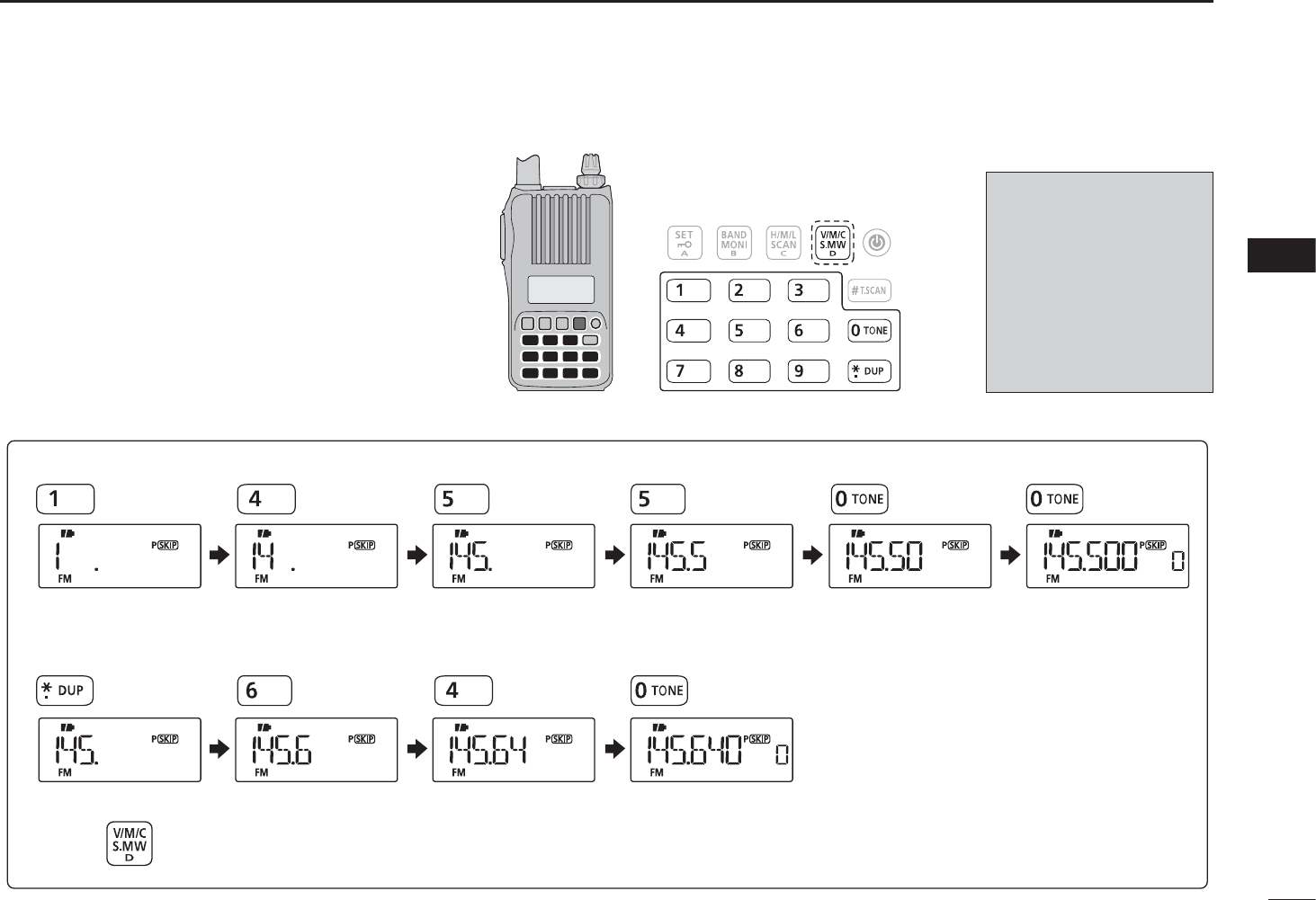
D Using the keypad
The frequency can be directly set via numeric
keys.
• If a frequency outside the frequency range is en-
tered, the previously displayed frequency is auto-
matically recalled after entering last digit.
q Push [V/M/C] to select the VFO mode, if any
other mode is selected.
w Enter the desired frequency via the keypad.
20
4
BASIC OPERATION
1
2
3
4
5
6
7
8
9
10
11
12
13
14
15
16
17
18
19
Depending on the
tuning step setting, it
may not be possible
to input a 1 kHz digit.
In this case, enter “0”
as 1 kHz digit, then ro-
tate [DIAL] to set the
desired frequency.
• Entering 145.580 MHz
• Changing 100 kHz and below
Editing 145.550 MHz to 145.640 MHz
Push to cancel numeral key input.
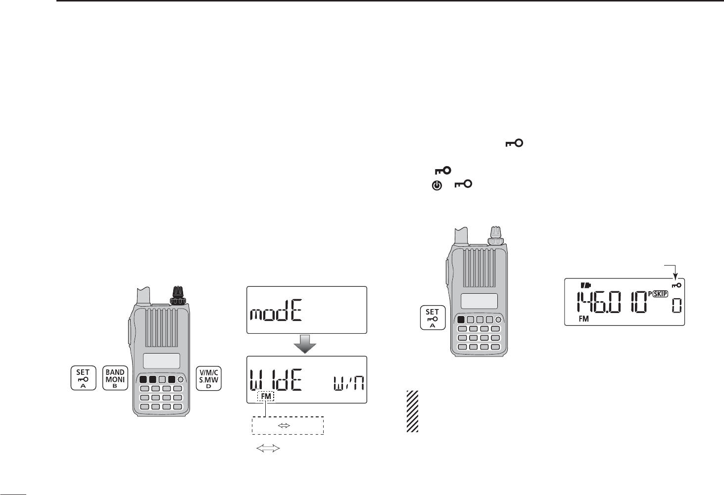
N Operating mode selection
Operating modes are determined by the modulation of the
radio signals. The transceiver has two operating modes, FM
and FM-N (narrow). The mode selection is stored indepen-
dently for each band and memory channel.
q Push [V/M/C] to select the VFO mode, if any other mode is
selected.
w Push [BAND] to select the desired frequency band.
e Push [SET] to enter the Set mode.
r Rotate [DIAL] to select the operating mode set item, then
rotate [VOL] to select “WIDE” (FM) or “nARROW” (FM-nar-
row).
tPush [V/M/C] to return to the VFO mode.
[VOL]
[DIAL]
: Rotate [VOL]
FM FMN
N Key lock function
To prevent accidental frequency changes and unnecessary
function access, use the lock function.
±Push and hold [](SET) for 1 sec. to turn the lock func-
tion ON or OFF.
• “ ” appears while the lock function is activated.
•[],[ ](SET), [MONI](BAND), [PTT],[VOL] and squelch ad-
justment ([MONI](BAND) + [DIAL]) are operable while the lock
function is activated.
Appears
To prevent accidental transmission, etc., the transceiver
has a PTT lock function. Turns the PTT lock function ON or
OFF in the Initial set mode. (p. 62)
21
4BASIC OPERATION
22
4
BASIC OPERATION
1
2
3
4
5
6
7
8
9
10
11
12
13
14
15
16
17
18
19
N Receiving
Make sure a charged battery pack (BP-264, BP-265) or brand
new alkaline batteries (BP-263) are installed (pp. 2, 12–14).
qPush and hold [] for 1 sec. to turn power ON.
w Rotate [VOL] to set the desired audio level. (p. 16)
• The frequency display shows the volume level while setting.
eSet the receiving frequency. (p. 20)
rSet the squelch level. (p. 17)
• While continuing to push [MONI](BAND), rotate [DIAL].
• The first click of [DIAL] indicates the current squelch level.
• “LEVEL1” is loose squelch (for weak signals) and “LEVEL9” is
tight squelch (for strong signals).
• “Auto” indicates automatic level adjustment by a noise pulse
counting system.
• Push and hold [MONI](BAND) to open the squelch manually.
t When a signal is received:
• Squelch opens and audio is output.
• The S/RF meter shows the relative signal strength level.
q
r Set squelch level
e Set frequency
r Push and hold for
setting the squelch
(Push and hold
to monitor)
e Select band
w Set audio level
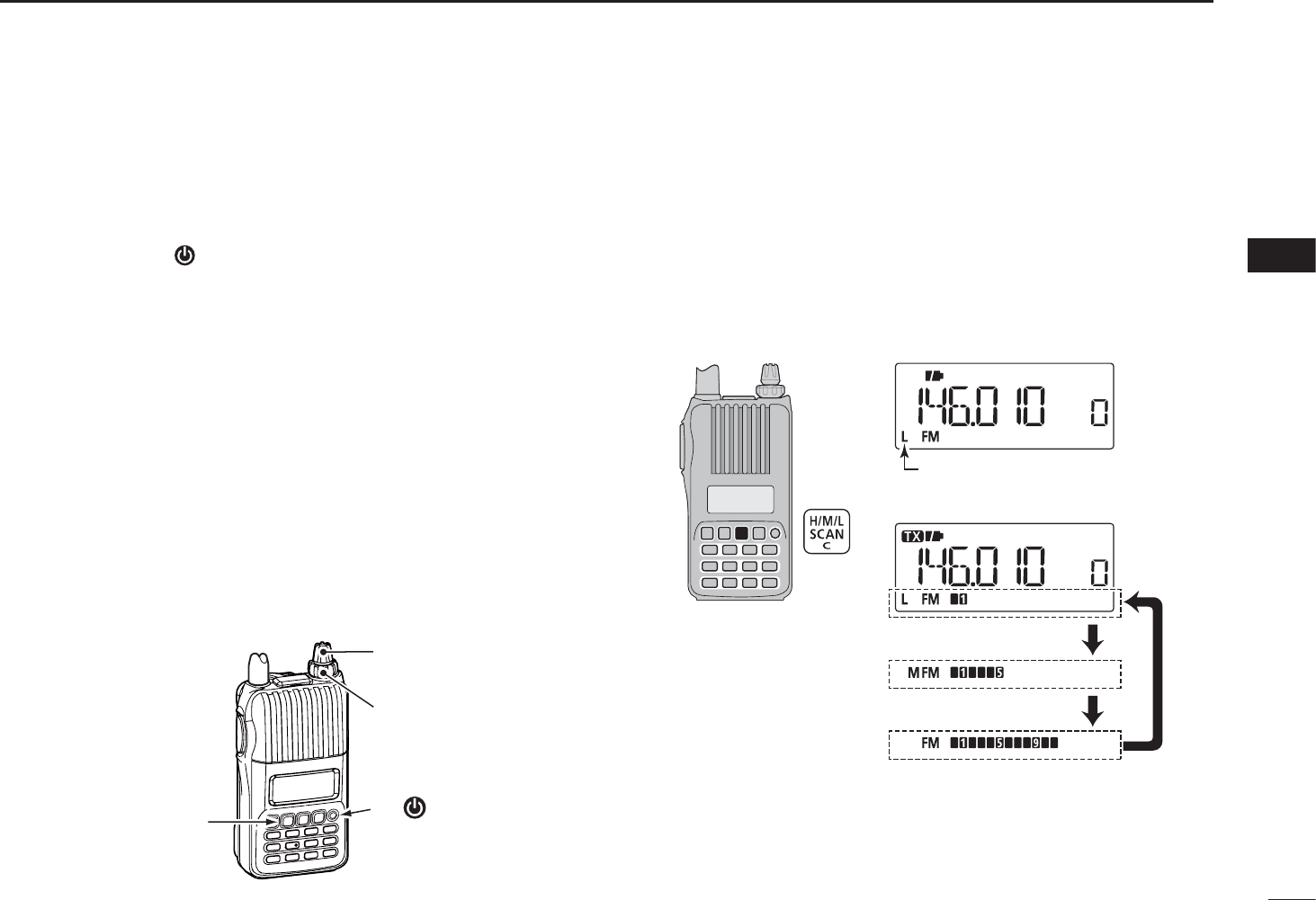
N Transmit power selection
The transceiver has three output power levels to suit your op-
erating requirements. Low output power during short-range
communications may reduce the possibility of interference to
other stations and will conserve battery power.
±
Push [H/M/L] to toggle the transmit output power between
High (5W*), Mid (2.5 W*) and Low (0.5 W*). *approx.
Appears
Low power transmission
Mid. power transmission
High power transmission
• During transmitting
23
4BASIC OPERATION
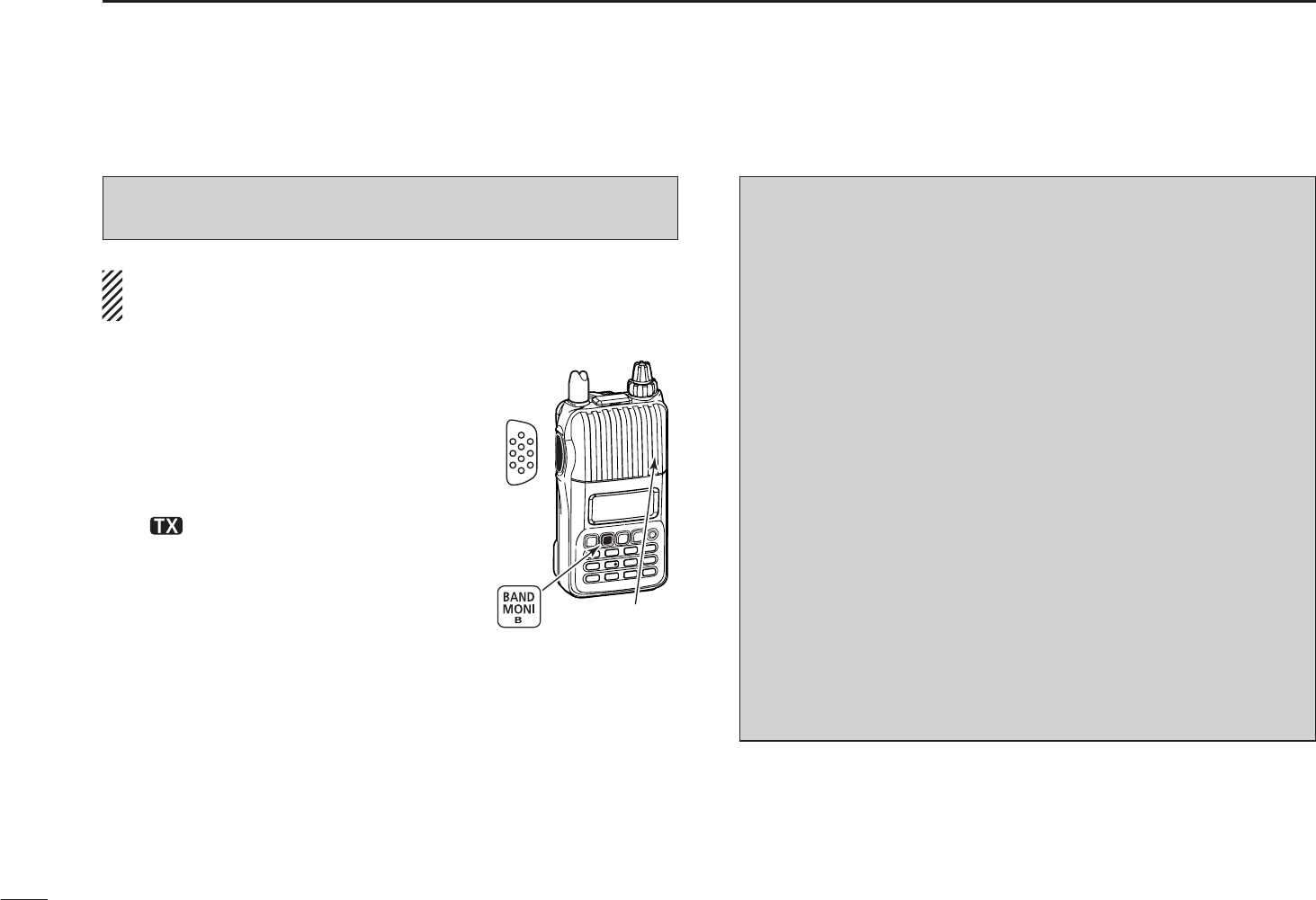
N Transmitting
NOTE: To prevent interference, push and hold [MONI]
(BAND) to listen on the frequency before transmitting.
Microphone
[PTT]
q Set the operating frequency. (p. 20)
• Transmission is available on the
144 MHz/400 MHz amateur bands only.
• Select output power if desired. See pre-
vious page for details.
w Push and hold [PTT] to transmit.
•“ ” appears.
• S/RF meter shows the output power
level.
e Speak into the microphone using
your normal voice level.
• DO NOT hold the transceiver too close
to your mouth or speak too loudly. This
may distort your speech.
rRelease [PTT] to return to receive.
RWARNING!
NEVER continuously transmit for long periods of time.
When the transceiver is used for continuous prolonged
transmission at high power, the transceiver radiates heat to
protect itself from overheating and transceiver’s chassis will
become hot. This may cause a burn.
DO NOT operate the transceiver in a situation that will ob-
struct heat dissipation, especially if the transceiver is oper-
ated with an external power supply. Heat dissipation may
be affected, and it may cause a burn, warp the casing or
damage the transceiver.
NOTE: When the transceiver becomes hot from continuous
transmission, etc., the transceiver’s heat protection gradu-
ally reduces the output power to 2.5 W (Mid), then it stops
transmission after that, to protect the transceiver itself until
it has cooled down.
• “M” (Power icon) blinks during the heat protection reduces the
output power.
• “Hot” is displayed during the heat protection inhibits the transmis-
sion.
CAUTION: Transmitting without an antenna will damage the
transceiver.
24
5
REPEATER AND DUPLEX OPERATIONS
1
2
3
4
5
6
7
8
9
10
11
12
13
14
15
16
17
18
19
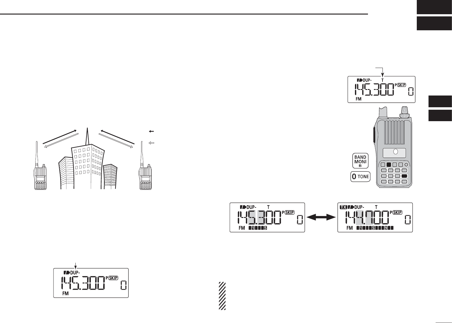
N Repeater operation
When using a repeater, the transmit frequency is shifted from
the receive frequency by the frequency offset (p. 54). This is
called duplex operation. It is convenient to program repeater
information into memory channels (p. 29).
Station A Station B
Repeater
145.300 MHz
144.700 MHz 144.700 MHz
145.300 MHz
Uplink
Downlink
(transmitting freq.)
(receiving freq.)
q Set the receive frequency (repeater output frequency).
w Set the shift direction of the transmit frequency. (DUP– or
DUP; see p. 26 for details.)
• When the auto repeater function is in use (U.S.A. and Korean
versions only), this selection and step e are not necessary.
(p. 27)
“DUP–”or “DUP” appears
[PTT]
T
Appears
e Push and hold [TONE](0) for 1 sec.
to activate the subaudible tone
encoder, according to repeater re-
quirements.
• “T” appears.
Refer to p. 53 for tone frequency set-
tings.
rPush and hold [PTT] to transmit.
• The displayed frequency automati-
cally changes to the transmit fre-
quency (repeater input frequency).
• If “OFF” appears, check the frequency
offset or shift direction. (p. 26)
While receiving While transmitting
tRelease [PTT] to receive.
y Push and hold [MONI](BAND) to check whether the other
station’s transmit signal can be directly received or not.
U.S.A. and Korean versions:
Auto repeater function uses standard values of the re-
peater tone frequency and frequency offset.
25
5REPEATER AND DUPLEX OPERATIONS
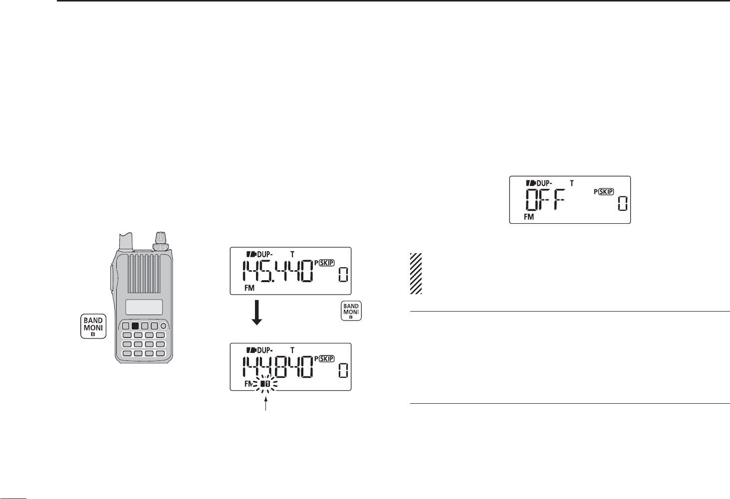
DChecking the repeater input signal
The transceiver can check whether the other station’s trans-
mit signal can be received directly or not, by listening on the
repeater input frequency.
±Push and hold [MONI](BAND) to check whether the other
station’s transmit signal can be received directly or not.
• When the other station’s signal can be directly received, move
to a non-repeater frequency to use simplex. (duplex OFF)
Display while receiving
Receives –0.6 MHz lower
Blinks while pushing and holding [MONI]
Push and hold
DOff band indication
If the transmit frequency is out of the amateur band when
[PTT] is pushed, the off band indication, “OFF,” appears on
the display. Check the frequency offset or duplex direction in
this case. (p. 26)
U.S.A. and Korean versions:
The auto repeater function uses standard values of the
frequency offset.
CONVENIENT!
Tone scan function: When you don’t know the subaudible
tone used for a repeater, the tone scan is convenient for de-
tecting the tone frequency.
±Push and hold [T.SCAN](#) for 1 sec. to start the tone
scan. See p. 71 for more information.
26
5
REPEATER AND DUPLEX OPERATIONS
1
2
3
4
5
6
7
8
9
10
11
12
13
14
15
16
17
18
19
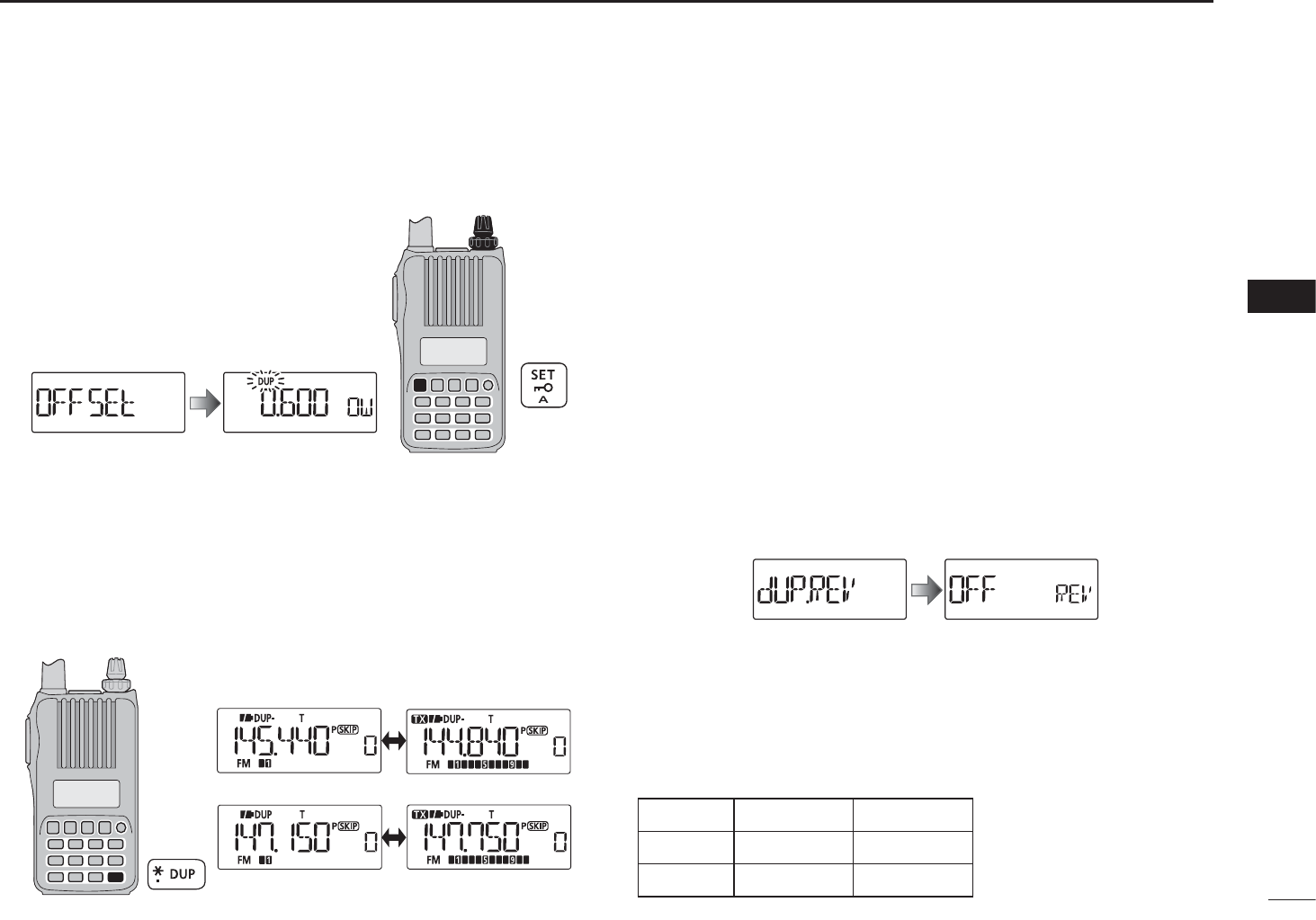
N Duplex operation
DSetting frequency offset
q Push [SET] to enter the Set mode.
w Rotate [DIAL] to select the frequency
offset set item, then rotate [VOL] to
set the frequency offset.
e Push [V/M/C] to return to the fre-
quency display.
Frequency offset
setting
0.6 MHz offset
DSetting duplex direction
±Push and hold [DUP](1) for 1 sec. to select “DUP–” (nega-
tive offset) or “DUP” (positive offset).
• “DUP–” or “DUP” indicates the transmit frequency for minus
shift or plus shift, respectively.
• When frequency offset is 0.6 MHz
–Duplex example
+Duplex example
Receiving Transmitting
U.S.A. and Korean versions:
The auto repeater function has priority over the manual duplex
setting. If the transmit frequency changes after setting, the
auto repeater function may have changed the duplex setting.
Turn the auto repeater function OFF to prevent this (p. 26).
N Reverse duplex function
When the reverse duplex function is ON, the receive and
transmit frequencies are reversed. The function can be set in
the Set mode.
qPush [SET] to enter the Set mode.
w Rotate [DIAL] to select the reverse duplex set item, then
rotate [VOL] to turn the function ON or OFF.
Reverse duplex setting
ePush [V/M/C] to return to the frequency display.
Each receive and transmit frequency is shown in the table
below, with the following configurations;
Input freq.:
145.300 MHz,
Direction: – (down), Offset: 0.6 MHz
• “DUP–” or “DUP” blinks
when the reverse duplex
function is ON.
Reversed
RX freq. TX freq.
OFF
145.300 MHz 144.700 MHz
ON
144.700 MHz 145.300 MHz
[DIAL]
[VOL]
27
5REPEATER AND DUPLEX OPERATIONS
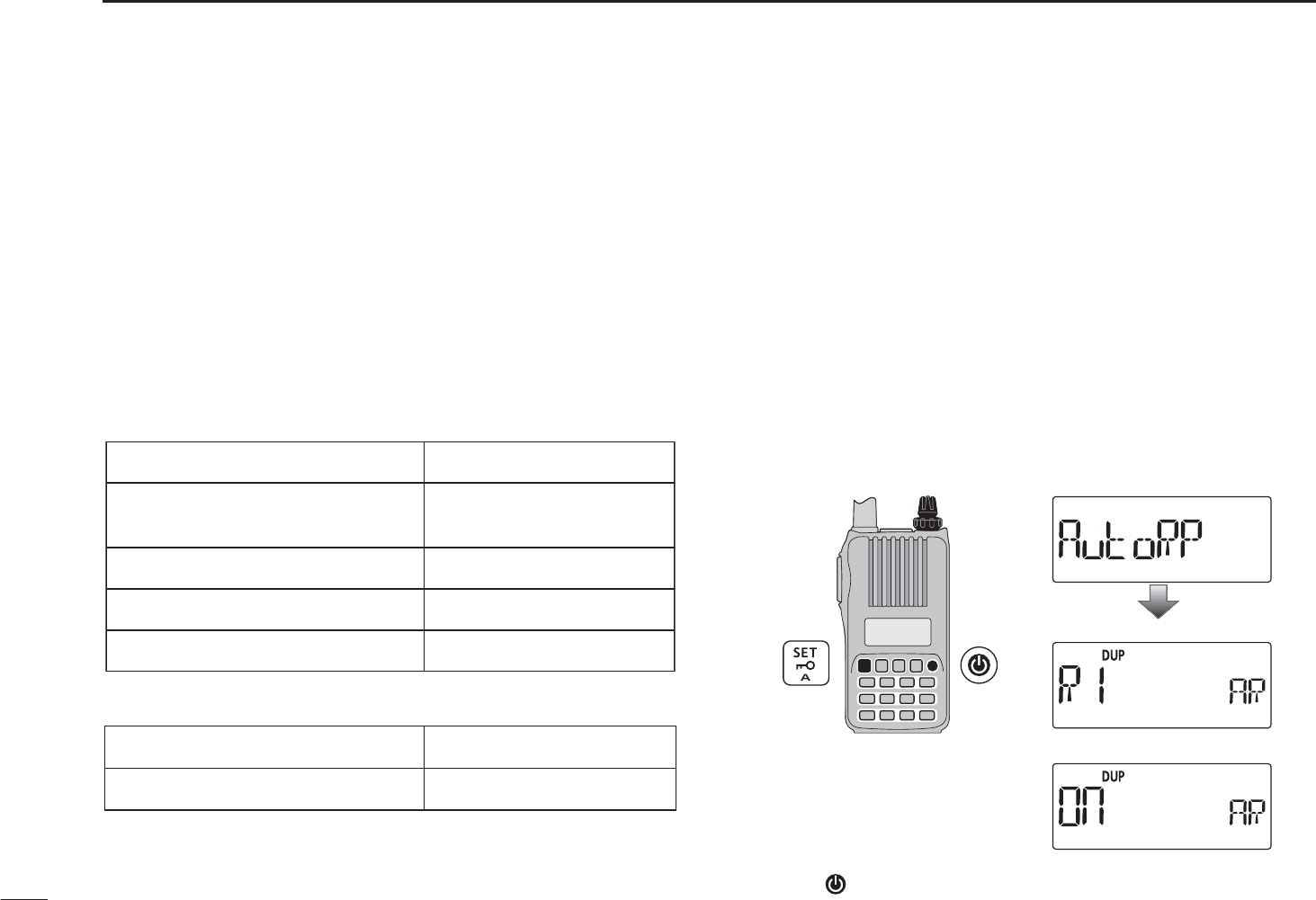
N Auto repeater function
The U.S.A. and Korean versions automatically use standard
repeater settings (duplex ON/OFF, duplex direction, tone encoder
ON/OFF) when the operating frequency falls within or outside
of the general repeater output frequency range. The offset
and repeater tone frequencies are not changed by the auto
repeater function. Reset these frequencies, if necessary.
DFrequency range and offset direction
• U.S.A. version
• Korean version
FREQUENCY RANGE SHIFT DIRECTION
439.000–440.000 MHz “DUP–” appears
q While continuing to push [SET], turn the power ON to
enter the Initial set mode.
w Rotate [DIAL] to select the auto repeater set item, then
rotate [VOL] to set the auto repeater setting.
U.S.A. version:
• “R1” : Activates duplex only. (default)
• “R2” : Activates duplex and tone.
• “OFF” : Auto repeater function is turned OFF.
Korean version:
• “On” : Activates duplex and tone. (default)
• “OFF” : Auto repeater function is turned OFF.
[VOL]
[DIAL]
U.S.A. version
Korean version
Auto repeater setting
e Push [ ] to return to the frequency display.
FREQUENCY RANGE SHIFT DIRECTION
147.000–147.395 MHz “DUP” appears
442.000–444.995 MHz “DUP” appears
447.000–449.995 MHz “DUP–” appears
145.200–145.495 MHz
146.610–146.995 MHz “DUP–” appears
28
5
REPEATER AND DUPLEX OPERATIONS
1
2
3
4
5
6
7
8
9
10
11
12
13
14
15
16
17
18
19
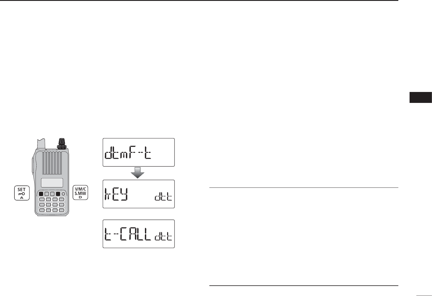
N 1750 Hz tone
To access some European repeaters, the transceiver must
transmit a 1750 Hz tone burst. For such European repeaters,
perform the following.
• This tone can be use as a ‘Call signal’ in countries out of Europe.
q Push [SET] to enter the Set mode.
w Rotate [DIAL] to select the DTMF key item, then rotate
[VOL] to set to “t-CALL.”
[VOL]
[DIAL]
Tone call setting
DTMF key setting
ePush [V/M/C] to return to the frequency display.
r Set the receive frequency (repeater output frequency).
t Set the shift direction of the transmit frequency. (–DUP or
+DUP; see p. 26 for details.)
y While continuing to push [PTT], push [MONI](BAND) to
transmit a 1750 Hz tone burst signal.
• If “OFF” appears, check the frequency offset or shift direction.
(p. 26)
• The displayed frequency automatically changes to the transmit
frequency (repeater input frequency).
uPush and hold [PTT] to transmit.
iRelease [PTT] to receive.
o Push and hold [MONI](BAND) to check whether the other
station’s transmit signal can be received directly or not, by
listening on the repeater input frequency.
CONVENIENT! (For the IC-T70E only)
q Set the receive frequency (repeater output frequency).
w Set the shift direction of the transmit frequency. (–DUP or
+DUP; see p. 26 for details.)
e Push [PTT] briefly, then push and hold [PTT] again for 1 to
2 sec. to transmit a 1750 Hz tone burst signal.
• If “OFF” appears, check the frequency offset or shift direction.
(p. 26)
• The displayed frequency automatically changes to the transmit
frequency (repeater input frequency).
rPush and hold [PTT] to transmit; release to receive.
29
MEMORY/CALL CHANNELS
6
N General description
The IC-T70A/T70E has 300 memory channels, and 2 call
channels. Memory channels include 50 scan edge memory
channels (25 pairs) for storage of often-used frequencies.
Also, 26 memory banks, A to Z, are available in each band for
storing groups of frequencies, etc. Up to 100 channels can be
assigned to a bank.
D Memory channel contents
The following information can be programmed into memory
channels:
• Operating frequency (p. 20)
• Operating mode (p. 21)
• Duplex direction (+DUP or –DUP) with a frequency offset
(p. 26)
• Reverse duplex function ON/OFF (p. 26)
• Subaudible tone encoder (p. 24), tone squelch or DTCS
squelch ON/OFF (p. 70)
• Subaudible tone frequency (p. 53), tone squelch fre-
quency or DTCS code with polarity (p. 53)
• Scan skip setting (p. 46)
• Memory bank (p. 32)
• Memory name (p. 34)
• Tuning step (p. 19)
• Output power (p. 22)
NOTE: Memory data can be erased by static electricity, electric transients, etc.
In addition, they can be erased by malfunction and during repairs. Therefore, we recommend that memory data be written down
or be saved to a PC using the CS-T70 CLONING SOFTWARE.
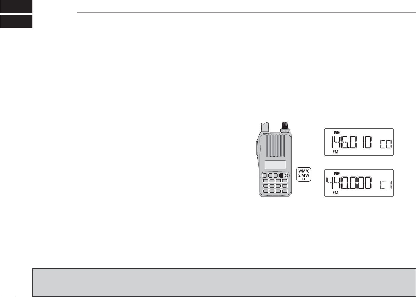
N Selecting a call channel
q Push [V/M/C] to select call channel mode.
• Pushing [V/M/C] toggles between the VFO mode, the memory
channel mode, call channel mode and weather channel mode*.
*Only the U.S.A. version transceiver.
w Rotate [DIAL] to select a desired call channel.
• “C0” and “C1” are selectable.
[DIAL] VHF band call channel
UHF band call channel
30
6
MEMORY/CALL CHANNELS
1
2
3
4
5
6
7
8
9
10
11
12
13
14
15
16
17
18
19
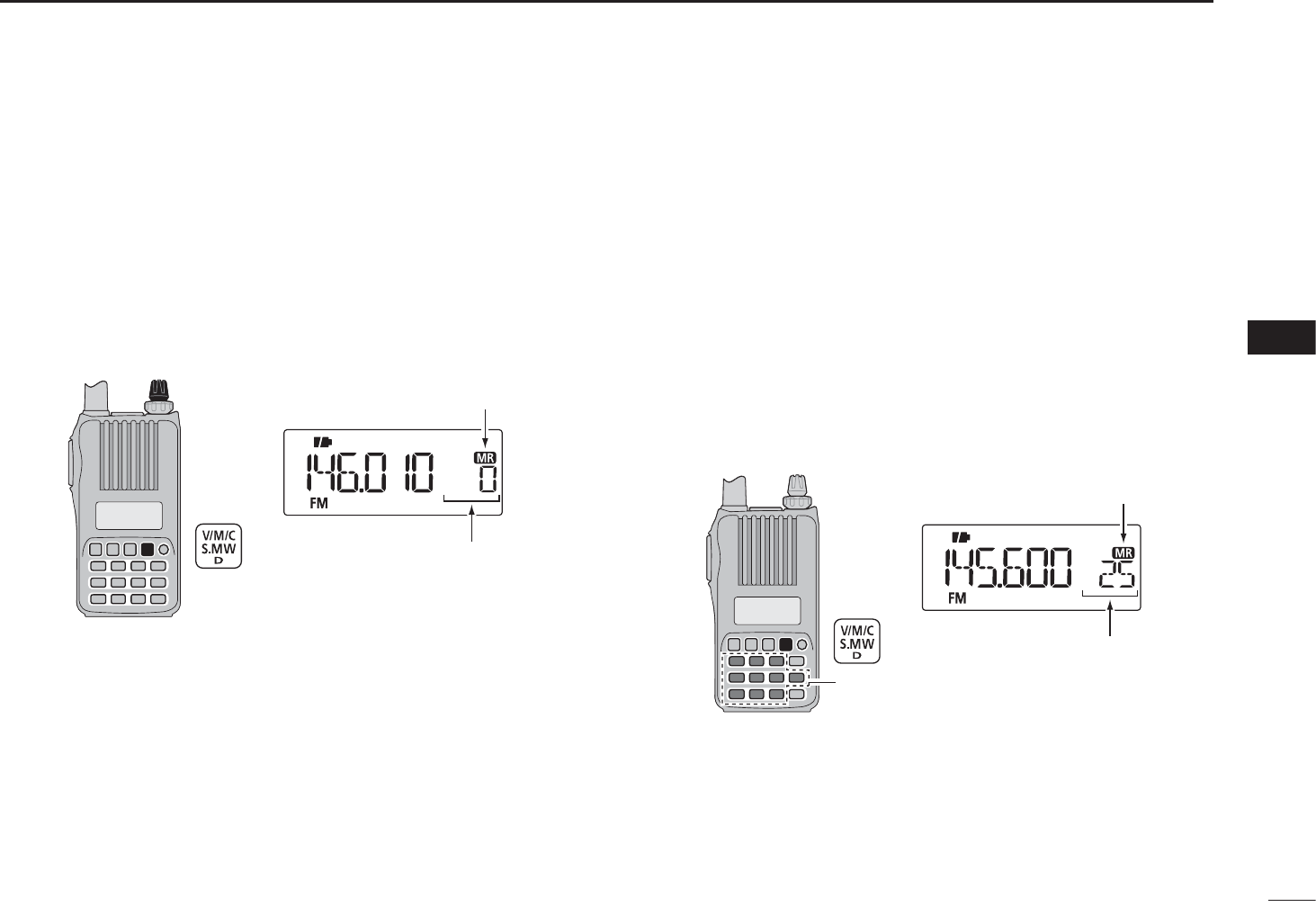
N Selecting a memory channel
D Using [DIAL]
q Push [V/M/C] to select the memory mode.
• Pushing [V/M/C] toggles between the VFO mode, the memory
channel mode, call channel mode and weather channel mode*.
*Only the U.S.A. version transceiver.
w Rotate [DIAL] to select a desired memory channel.
• Only programmed channels are displayed.
[DIAL] Appears
Rotate [DIAL] to select
the memory channel.
D Using the Numeral keys
q Push [V/M/C] to select the memory mode.
• Pushing [V/M/C] toggles between the VFO mode, the memory
channel mode, call channel mode and weather channel mode*.
*Only the U.S.A. version transceiver.
w Use the numeral keys to enter 3 digits to select a desired
memory channel.
• The blank channels are also selectable.
• Example— selecting memory channel “25”
Push [V/M/C], then push [0],[2],[5].
Appears
Numeral
keys
The entered memory
channel is selected.
31
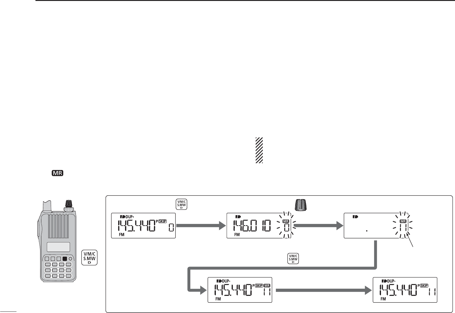
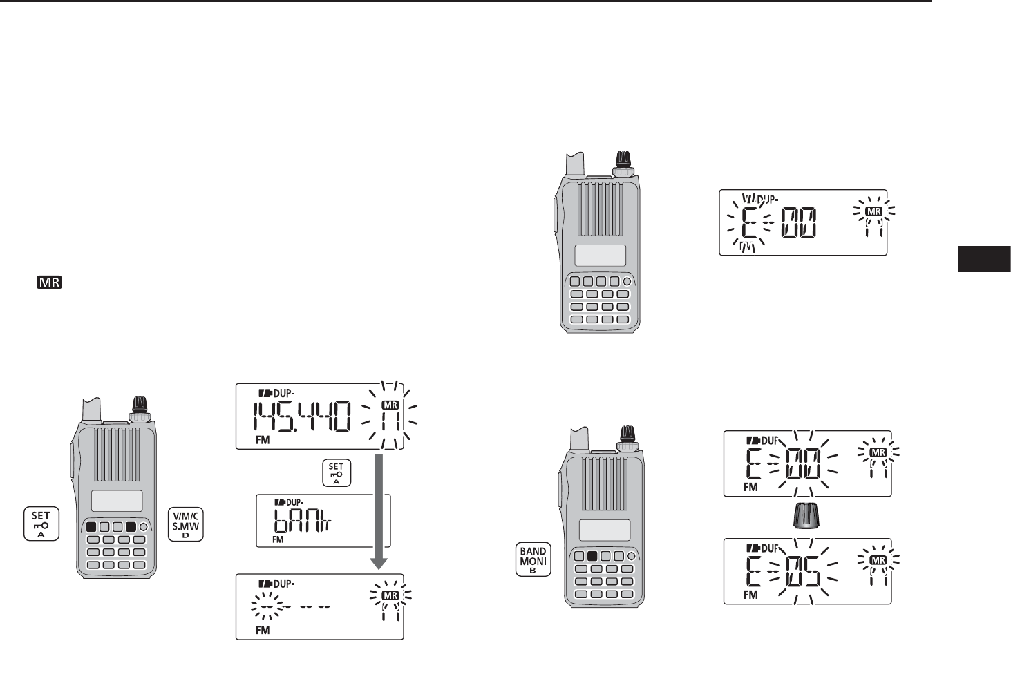
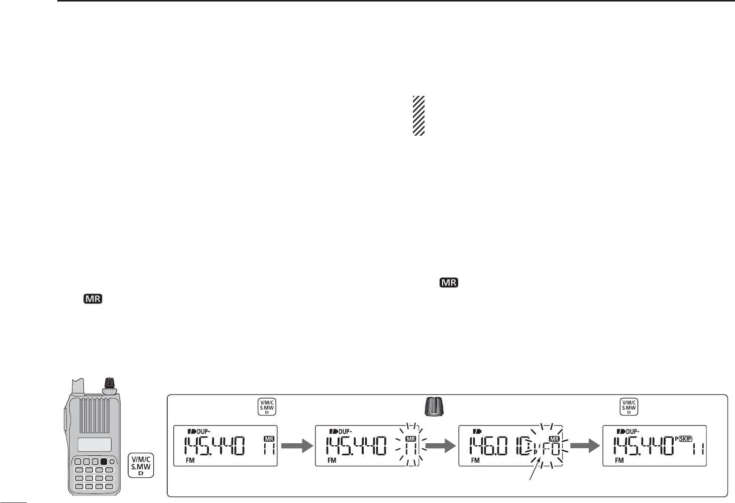
6MEMORY/CALL CHANNELS
qPush [V/M/C] to select the VFO mode.
wSet a desired frequency:
± Select a desired band with [BAND].
± Set a desired frequency with [DIAL].
± Or set a desired frequency with keypad directly.
In this case, the band and frequency settings with
[BAND] and [DIAL] as above are not required.
±Set other data (e.g. frequency offset, duplex direction,
tone squelch, etc.), if desired.
e Push and hold [S.MW](V/M/C) for 1 sec. to enter the select
memory write mode.
• 1 short and 1 long beep sound.
•“ ” icon and memory channel number blink.
rRotate [DIAL] to select a desired channel.
• Call channels (C0, C1), VFO and scan edge channels (0A/0b
to 24A/24b), as well as regular memory channels, can be pro-
grammed in this way.
tPush and hold [S.MW](V/M/C) for 1 sec. to program.
• 3 beeps sound.
• Memory channel number automatically increases when continu-
ing to push [S.MW](V/M/C) for 1 sec. after programming.
NOTE: Push [H/M/L] to cancel to program and exit the
select memory write mode before memory programming is
finished.
[DIAL]
The VFO mode Enter the select memory write mode.
to select channel 11.Rotate
Push and hold for 1 sec.
Return to the VFO mode.
Push and hold for 1 sec. to program.
[EXAMPLE]: Programming 145.440 MHz into memory channel 11 (a blank channel).
Channel 11
NMemory channel programming
32
6
MEMORY/CALL CHANNELS
1
2
3
4
5
6
7
8
9
10
11
12
13
14
15
16
17
18
19
N Memory bank setting
The IC-T70A/T70E has a total of 26 banks (A to Z). Memory
channels 0 to 249 are assigned to any desired bank for easy
memory management.
q Push and hold [S.MW](V/M/C) for 1 sec. to enter the select
memory write mode.
• 1 short and 1 long beep sound.
•“ ” icon and memory channel number blink.
wRotate [DIAL] to select a desired memory channel.
e Push [SET] to select “bAnk” item.
• Bank group and channel number are displayed if the selected
memory channel has already been assigned to a bank.
[DIAL]
Push
r Rotate [DIAL] to select a desired bank group from “A” to “Z.”
[DIAL]
t Push [BAND] to select the bank channel digit, then rotate
[DIAL] to select the bank channel number from “00” to “99.”
• Push [BAND] to toggle the bank group selection and bank chan-
nel selection.
[DIAL]
Rotate
y Push and hold [S.MW](V/M/C) for 1 sec. to assign the
channel to the bank.
• Return to the previous indication before entering the select
memory write mode.
33
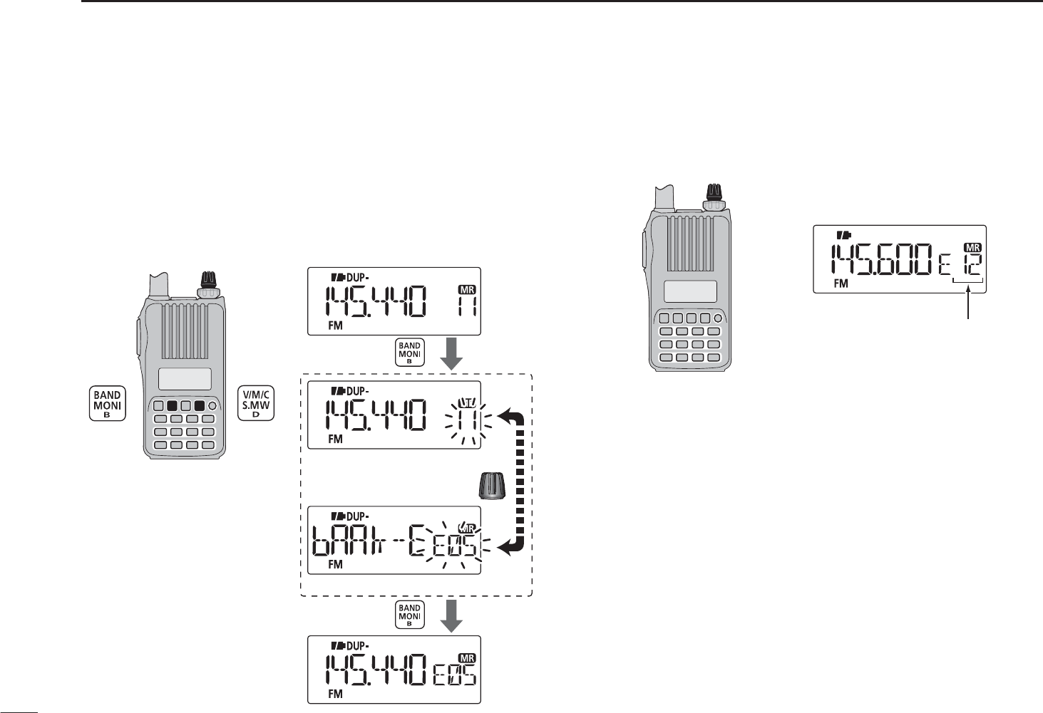
6MEMORY/CALL CHANNELS
N Memory bank selection
q Push [V/M/C] to select the memory mode.
w Push [BAND] to enter the bank selection mode.
e Rotate [DIAL] to select a desired bank (A to Z), then push
[BAND].
• Only programmed banks are displayed.
• Also regular memory channel can be selected.
[DIAL]
Push
Rotate
Bank channel is displayed.
Regular memory
channel
is displayed.
Push
r Rotate [DIAL] to select the bank channel.
• Only programmed channels are displayed.
[DIAL]
Bank channel is selected.
34
6
MEMORY/CALL CHANNELS
1
2
3
4
5
6
7
8
9
10
11
12
13
14
15
16
17
18
19
N Programming memory/bank/scan name
Each memory channel can be programmed with an alpha-
numeric channel name for easy recognition and can be indi-
cated independently by channel. Names can be a maximum
of 6 characters.
NOTE: Scan name indication can be turned ON or OFF in
the Initial set mode. (p. 34)
qPush [V/M/C] to select the memory mode.
w Push and hold [S.MW](V/M/C) for 1 sec. to enter the select
memory write mode.
• 1 short and 1 long beep sound.
•“ ” icon and memory channel number blink.
eRotate [DIAL] to select a desired memory channel.
• Select Call channels (C0 or C1) or scan edge channels (0A/0b
to 24A/24b) to program a call channel name or scan name, re-
spectively.
r Push [SET] repeatedly to select “b nAmE,” “m nAmE” or
“S nAmE” when programming the bank name, the memory
name or the scan name, respectively.
t Push and hold [SET] for 1 sec. to enter the name program-
ming mode.
• After selecting the name to be programmed, a cursor blinks for
the first character.
y Rotate [DIAL] to select a desired character.
• The selected character blinks.
• Push [BAND] to move the cursor right; push [SET] to move the
cursor left.
u Repeat step y until a desired channel name is pro-
grammed.
i Push and hold [S.MW](V/M/C) for 1 sec. to set the name
and exit channel name programming state.
• 3 beeps sound.
NOTE: Only one bank name can be programmed into each
bank. Therefore, the previously programmed bank name
will be displayed when bank name indication is selected.
Also, the programmed bank name is assigned for the other
bank channels automatically.
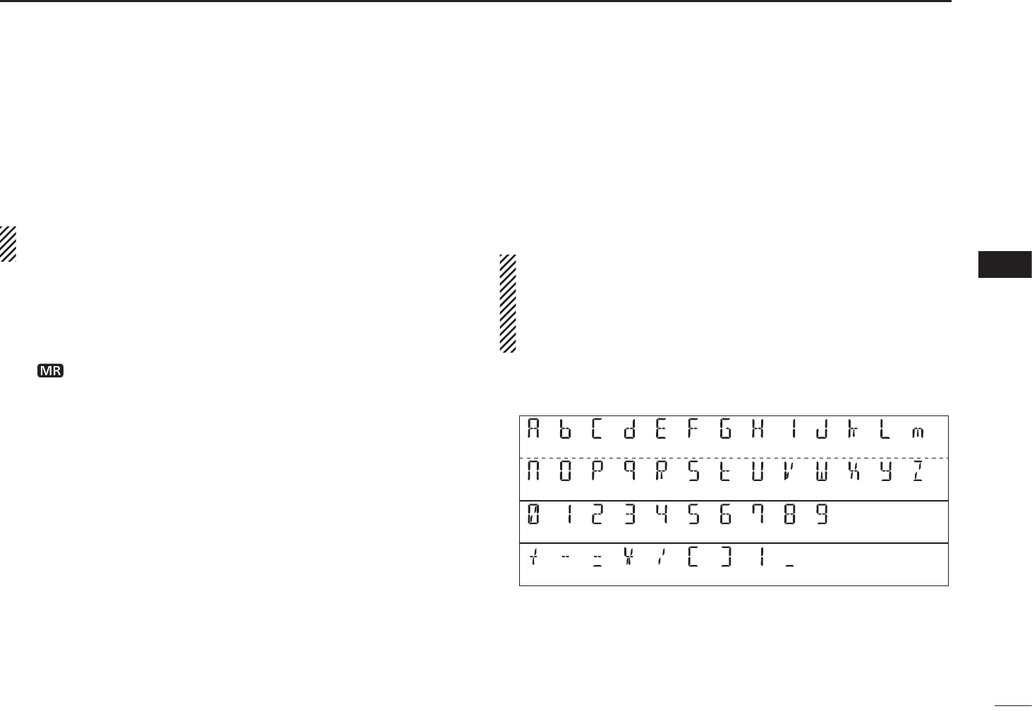
D Usable characters
(A) (b) (C) (d) (E) (F) (G) (H) ( I ) (J) (k) (L) (m)
(n) (O) (P) (q) (R) (S) (t) (U) (V) (W)
(9)(0) (1) (2) (3) (4) (5) (6) (7) (8)
(+) (:)
(=) (
(
)(
)
)
(
)
(X) (y) (Z)
(-) (
/
)
(Space)
35
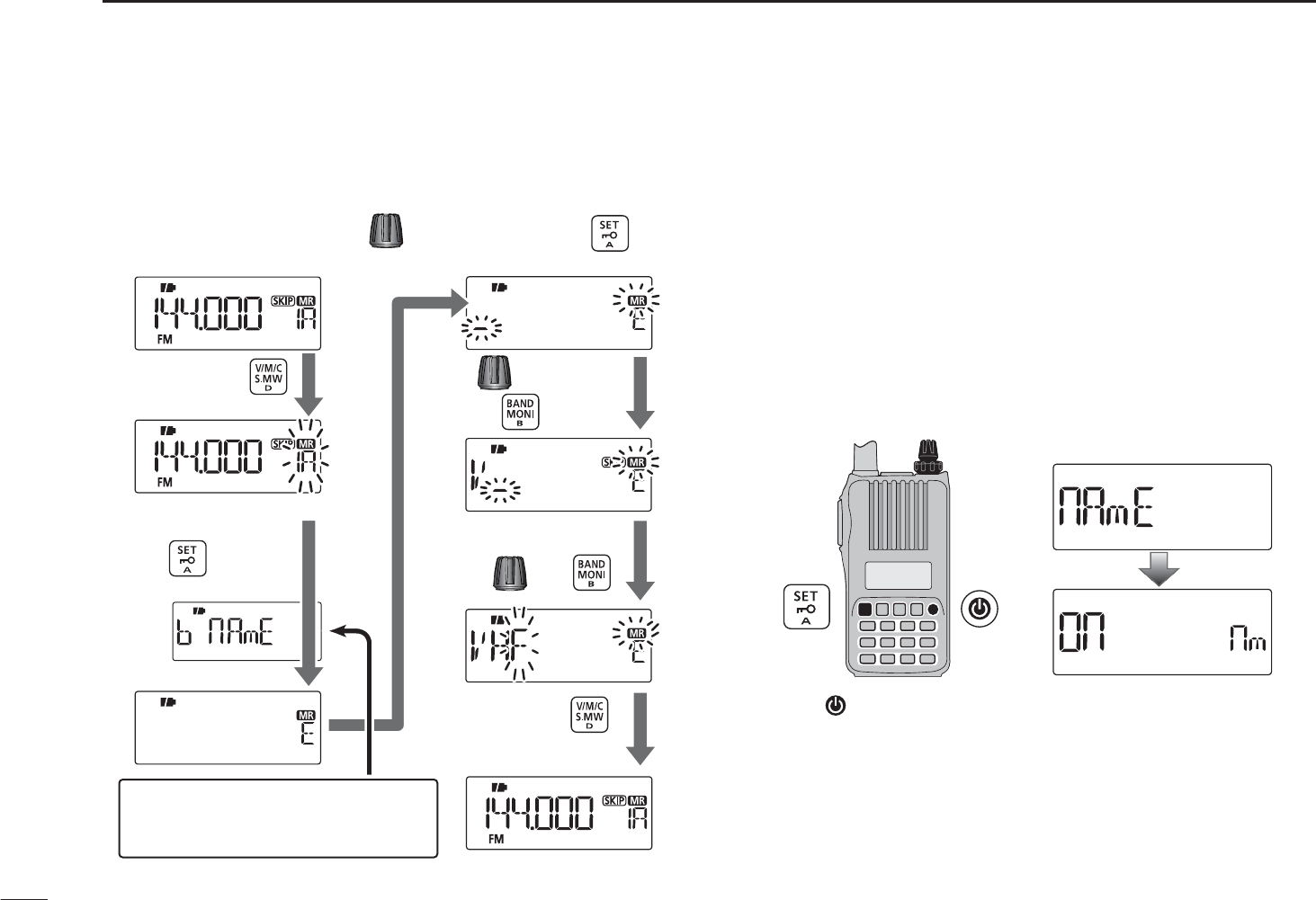
6MEMORY/CALL CHANNELS
NProgramming memory/bank/scan name (continued)
[EXAMPLE]: Programming the bank name “VHF” into the
scan edge channel 1A
NSelecting memory/bank
name indication
During memory mode operation, either the programmed
memory name or bank name can be displayed.
q While continuing to push [SET], turn the power ON to
enter the Initial set mode.
w Rotate [DIAL] to select the memory name item, then rotate
[VOL] to set the memory name indication setting.
• “OFF” : Memory name indication is turned OFF.
• “On” : Activates the memory name indication. (default)
[VOL]
[DIAL] Memory name setting
e Push [ ] to return to the frequency display.
Push and hold
for 1 sec.
Push and hold
for 1 sec.
Enter the select memory
write mode.
Push repeatedly
to select “b nAmE*2.”
Push and hold
for 1 sec. to program.
During memory mode, rotate
to select scan edge channel 1A.
Rotate to select “V,”
then push .
Select “H” and “F”
with and .
*1 S nAmE can be set for scan edge channels only.
*2 b nAmE can be set for bank assigned channels only.
Select “m nAmE” or “S nAmE*
1
”
when programming the memory
name or the scan name, respectively.

36
6
MEMORY/CALL CHANNELS
1
2
3
4
5
6
7
8
9
10
11
12
13
14
15
16
17
18
19
NDisplay type
During memory mode operation, the transceiver has 3
display types to suit your operating style. Set the display type
in the Initial set mode.
q While continuing to push [SET], turn the power ON to
enter the Initial set mode.
w Rotate [DIAL] to select the display mode item, then rotate
[VOL] to set the display type from “FREq,” “CH” or “PRIV.”
[VOL]
[DIAL] Display mode setting
e Push [ ] to return to the frequency display.
“Frequency display”
Displays the programmed fre-
quency. (default)
“Channel number display”
Displays the memory chan-
nel number. Only programmed
memory channels are displayed,
and modes other than the memory
mode cannot be selected.
• When the channel number display type is selected, only the
following functions can be performed.
- Scan function (p. 44) - Output power setting (p. 22)
- Monitor function (p. 17) - Key lock function (p. 21)
- DTMF transmit function (p. 66)
- The scan pause timer setting, the scan resume timer setting, the
DTMF memory selection, the mic gain setting and the VOX gain
setting in the Set mode.
“Private channel display”
Displays the memory channel
number. Only programmed mem-
ory channels 0 to 5 are displayed,
and modes other than the memory
mode cannot be selected.
• When the private channel display type is selected, only the
following functions can be performed.
- Output power setting (p. 22) - Monitor function (p. 17)
- Key lock function (p. 21) - DTMF transmit function (p. 66)
37
6MEMORY/CALL CHANNELS
N Copying memory/call contents
This function transfers a memory channel’s contents to VFO
(or another memory/call channel). This is useful when search-
ing for signals around a memory channel frequency and for
recalling the frequency offset, subaudible tone frequency etc.
D Memory/call¶VFO
qSelect the memory (call) channel to be copied.
±Push [V/M/C] repeatedly to select the memory mode
or the call channel mode, then rotate [DIAL] to select a
desired channel.
w Push and hold [S.MW](V/M/C) for 1 sec. to enter the select
memory write mode.
• 1 short and 1 long beep sound.
•“ ” icon and memory channel number blink.
eRotate [DIAL] to select “VFO.”
r Push and hold [S.MW](V/M/C) for 1 sec. to write the se-
lected channel contents to the VFO mode.
• Returns to the VFO mode automatically.
Pushing and holding [S.MW](V/M/C) for 2 seconds at step
w, will also copy the memory contents to VFO. In this
case, steps e and r are not necessary.
DMemory/call¶memory/call
qSelect the memory (call) channel to be copied.
±Push [V/M/C] repeatedly to select the memory mode
or the call channel mode, then rotate [DIAL] to select a
desired channel.
w Push and hold [S.MW](V/M/C) for 1 sec. to enter the select
memory write mode.
• 1 short and 1 long beep sound.
•“ ” icon and memory channel number blink.
• Do not hold [S.MW](V/M/C) for more than 2 seconds otherwise
the memory contents will be copied to the VFO mode.
eRotate [DIAL] to select the target memory (call) channel.
rPush and hold [S.MW](V/M/C) for 1 sec. again to copy.
[DIAL]
Memory mode Enter
the select memory write mode.
to select “VFO.”Rotate
Push and hold for 1 sec.
“VFO” is selected. Return to the VFO mode.
Push and hold for 1 sec.
[EXAMPLE]: Copying memory channel 11 to the VFO mode.
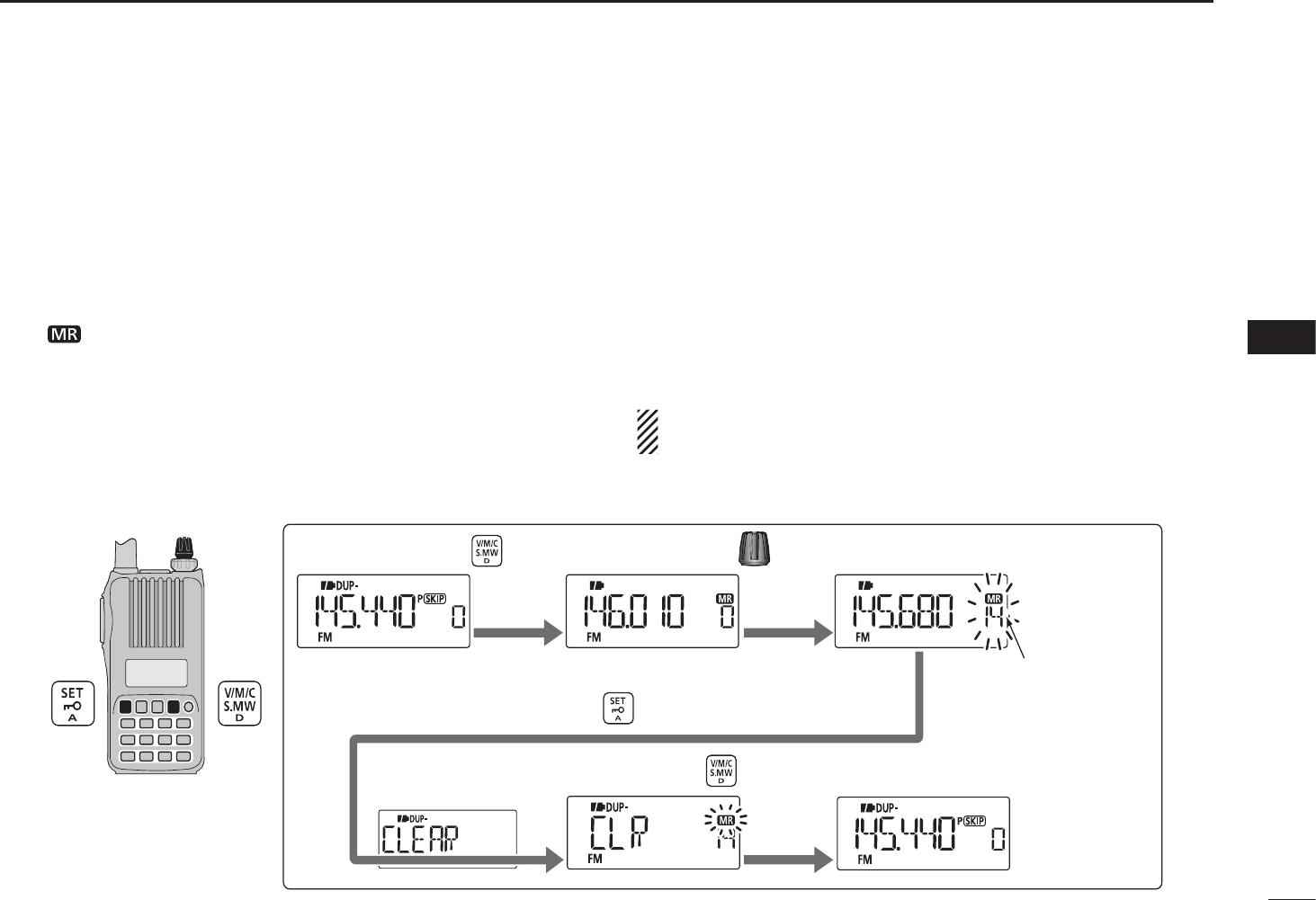
38
6
MEMORY/CALL CHANNELS
1
2
3
4
5
6
7
8
9
10
11
12
13
14
15
16
17
18
19
Contents of programmed memories can be cleared (erased),
if desired.
q Push and hold [S.MW](V/M/C) for 1 sec. to enter the select
memory write mode.
• 1 short and 1 long beep sound.
•“ ” icon and memory channel number blink.
• Do not hold [S.MW](V/M/C) for more than 2 seconds otherwise
the memory contents will be copied to the VFO mode.
w Rotate [DIAL] to select a desired memory channel to be
cleared.
e Push [SET] repeatedly to select “CLEAR.”
r Push and hold [S.MW](V/M/C) for 1 sec. to clear the con-
tents.
• 3 beeps sound.
• The cleared channel changes to blank channel
• Return to the select memory write mode.— Memory channel
number blinks. Push [H/M/L] to exit the select memory write
mode.
NOTE: Be careful!— the contents of cleared memories
CANNOT be recalled.
[DIAL]
The VFO mode Enter the select memory write mode.
to select a desired channel.Rotate
Push and hold for 1 sec.
Channel 14
Push repeatedly to select “CLEAR.”
Push and hold for 1 sec to clear and return to the VFO mode.
[EXAMPLE]: Clearing memory channel 14.
NMemory clearing
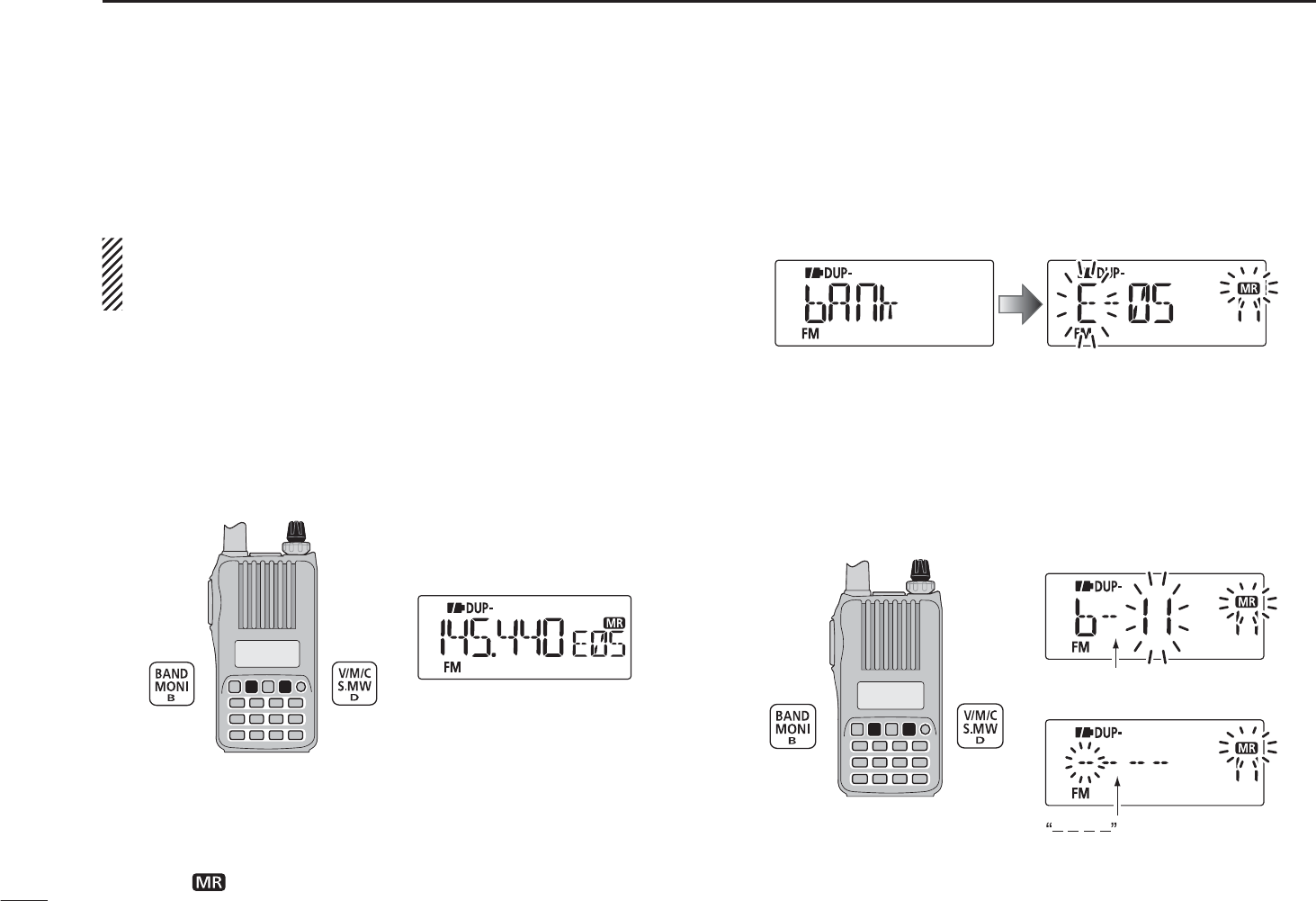
39
6MEMORY/CALL CHANNELS
N Erasing/transferring bank contents
The bank contents of programmed memory channels can be
cleared or reassigned to another memory bank.
INFORMATION: Even if the memory bank contents are
cleared, the memory channel contents still remain
programmed.
q Select a desired bank contents to be transferred or erased
from the bank. (p. 33)
±Push [BAND] to enter the memory bank selection
mode.
±Rotate [DIAL] to select a desired memory bank group,
then push [BAND].
±Rotate [DIAL] to select the bank channel.
[DIAL]
w Push [S.MW](V/M/C) for 1 sec. to enter the select memory
write mode.
• 1 short and 1 long beeps sound.
• Displays the original memory channel number automatically, and
then “ ” icon and memory channel number blink.
• Do not hold [S.MW](V/M/C) for more than 2 seconds, otherwise
the memory contents will be copied to VFO.
e Push [SET] repeatedly to select “bAnk.”
r Push [BAND] to toggle the bank channels selection or the
bank group selection.
t Rotate [DIAL] to select a desired bank group or channel to
be transferred.
• Select “– – – –” display when erasing the contents from the
bank.
[DIAL]
To transfer the bank contents
to ch 11 in Bank b.
To erase
Bank channel is displayed.
is displayed.
y Push [S.MW](V/M/C) for 1 sec. to erase/transfer the bank
contents.
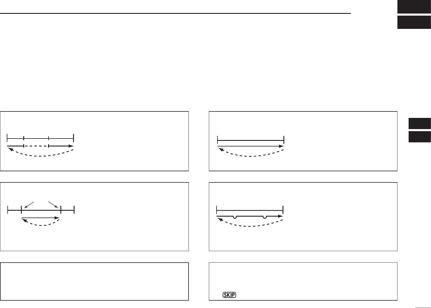
40
7
SCAN OPERATION
1
2
3
4
5
6
7
8
9
10
11
12
13
14
15
16
17
18
19
N Scan types
Scanning searches for signals automatically and makes
it easier to locate new stations for contact or listening pur-
poses.
FULL SCAN (p. 42)
Repeatedly scans all frequen-
cies over the entire band.
Some frequency ranges are not
scanned according to the fre-
quency coverage of the trans-
ceiver’s version.
SELECTED BAND SCAN (p. 42)
Repeatedly scans all frequen-
cies over the entire selected
band.
FREQUENCY/MEMORY SKIP FUNCTION
Skips unwanted frequencies or
channels that inconveniently
stop scanning.
This setting can be turned ON or
OFF in the select memory write
mode. (p. 46)
PROGRAMMED SCAN (p. 42)
Repeatedly scans between two
user-programmed frequencies.
Used for checking for frequen-
cies within a specified range
such as repeater output fre-
quencies, etc.
144 MHz
band
440 MHz
band
ScanScan
Jump
Band
edge
Band
edge
Scan
Jump
Band
edge xxA xxB
Band
edge
Scan edges
Scan
Jump
Band
edge
Band
edge
Scan
SKIP SKIP
Jump
PROGRAMMED LINK SCAN (pp. 42, 57)
Repeatedly programmed scans user-programmed frequen-
cies selected at “P LInk” item in the Set mode.
The frequency skip scan function can be turned ON or OFF
in the Set mode. When this function is set to ON, the speci-
fied frequencies are skipped during VFO scan. (p. 55)
•“P” icon appears in the VFO mode.
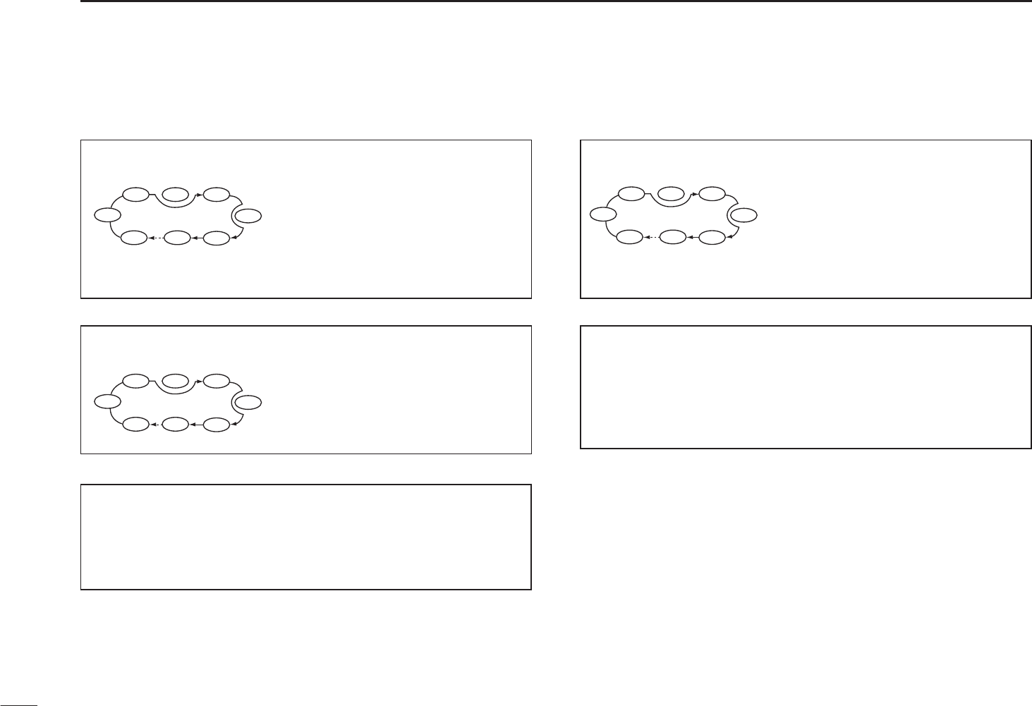
41
7SCAN OPERATION
ALL/SELECTED BANK SCAN (p. 45)
Repeatedly scans all bank chan-
nels or selected bank channels.
The skip scan is also available.
MEMORY (SKIP) SCAN (p. 44)
Repeatedly scans memory
channels except those set as
skip channel.
Skip channels can be turned ON
or OFF in the select memory
write mode. (p. 46)
BAND MEMORY (SKIP) SCAN (p. 44)
Repeatedly scans memory
channels in the same band as
displayed band.
BANK-LINK SCAN (pp. 45, 46)
Repeatedly scans bank channels selected at “b LInk” item
in the Set mode.
DUPLEX SCAN (pp. 42, 44)
Repeatedly scans two (transmission/reception) frequencies
during duplex scan operation.
N Scan types (continued)
SKIP
SKIP
M0 M4
M1 M2 M3
M5
M 249
M6
SKIP
440 MHz
band 440 MHz
band
Example: While scaning the 144 MHz band
SKIP
M0 M4
M1 M2 M3
M5
M 249
M6
SKIP
SKIP
A99 A03
A00 A01 A02
A04
A98
A05
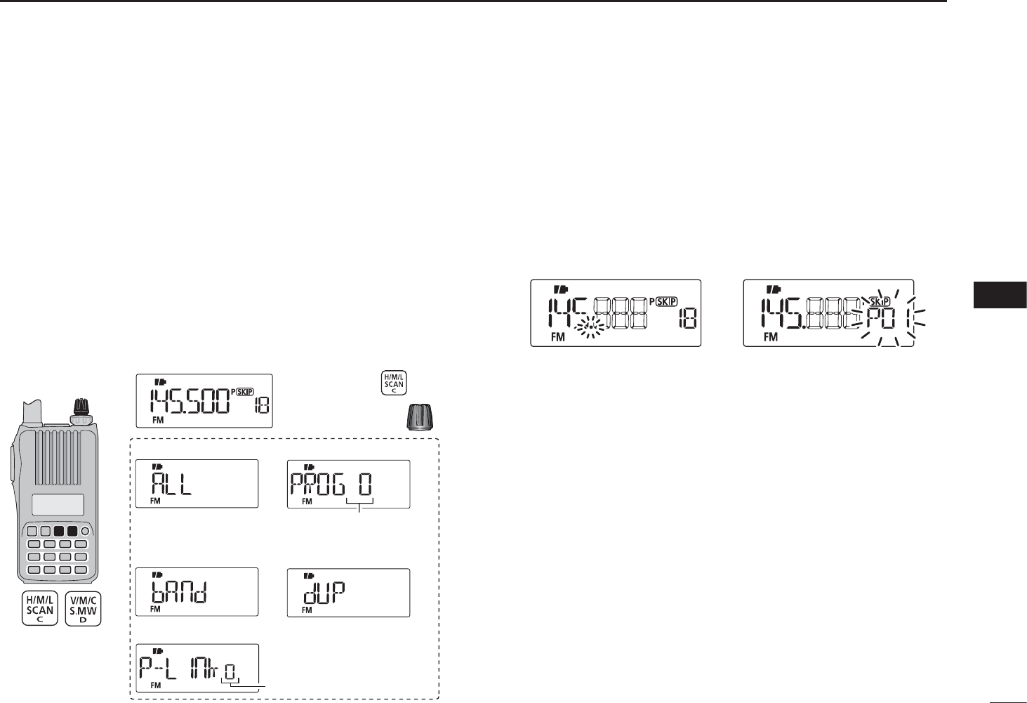
N Full/band/programmed scan
qPush [V/M/C] to select the VFO mode.
• Select a desired frequency band with [BAND], if desired.
wSet the squelch level.
e Push and hold [SCAN](H/M/L) for 1 sec. to enter the scan-
ning type selection.
r Rotate [DIAL] to select a desired scanning type.
• “ALL” for full scan; “bAnd” for band scan, “P-LInk x” for pro-
grammed link scan (x= 0 to 9), “PROGxx (or scan name if pro-
grammed)” for programmed scan (xx= 0 to 24; only programmed
scan edge numbers are displayed), “dUP” (appears only when
duplex operation is set) for duplex scan.
[DIAL]
Full scan
Band scan Duplex scan
Programmed link scan
Push and hold
for 1 sec.
Programmed scan
Rotate
Selectable from “0” to “9.”
Selectable from “0” to “24,”
if programmed.
tPush [SCAN](H/M/L) to start the scan.
• Scan pauses when a signal is received.
• Rotate [DIAL] to change the scanning direction. This also
causes the transceiver to resume scanning.
• Push [V/M/C] to stop the scan.
• Push [BAND] to change the band during band scan, or change
the scan edge during programmed scan/program link scan.
During full/band scan During programmed scan
Scan name can be displayed instead of “P-LInk x” for pro-
gram link scan (x= 0 to 9), “PROGxx” for programmed scan
(xx= 0 to 24) when scan name is programmed and set to ON
in the Initial set mode.
Scan name is not displayed during scan.
42
7
SCAN OPERATION
1
2
3
4
5
6
7
8
9
10
11
12
13
14
15
16
17
18
19
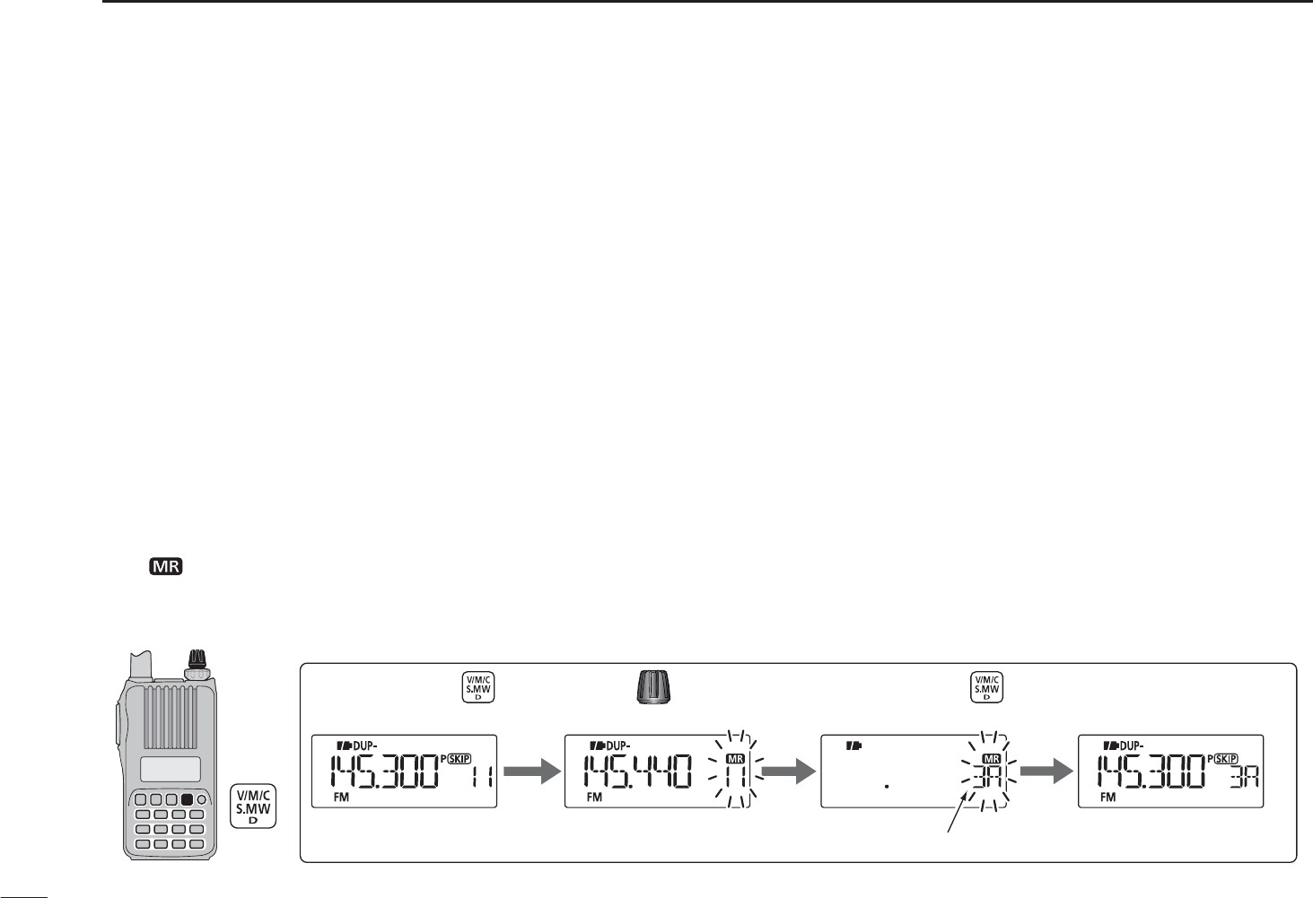
43
7SCAN OPERATION
N Scan edges programming
Scan edges can be programmed in the same manner as
memory channels. Scan edges are programmed into scan
edges, 0A/0b to 24A/24b, in memory channels.
qPush [V/M/C] to select the VFO mode.
wSet a desired frequency:
± Select a desired band with [BAND].
± Set a desired frequency with [DIAL].
±Program different frequencies in “1A” and “1b” respec-
tively.
±Set other data (e.g. frequency offset, duplex direction, tone
squelch, etc.), if desired.
e Push and hold [S.MW](V/M/C) for 1 sec. to enter the select
memory write mode.
• 1 short and 1 long beep sound.
•“ ” icon and memory channel number blink.
r Rotate [DIAL] to select a desired programmed scan edge
channel from 0A to 24A.
tPush and hold [S.MW](V/M/C) for 1 sec.
• 3 beeps sound.
• The other scan edge channel “b,” 0b to 24b, is automatically se-
lected when continuing to push [S.MW](V/M/C) after program-
ming.
y To program a frequency for the other pair of scan edges,
0b to 24b, repeat steps w and r.
• If the same frequency is programmed into a pair of scan edges,
programmed scan will not function.
[DIAL]
The VFO mode Enter
the select memory write mode.
to selectRotate
Push and hold
for 1 sec. “3A.”
“3A” is selected. Return to the VFO mode.
Push and hold
for 1 sec.
[EXAMPLE]: Programming 145.300 MHz into scan edges 3A.
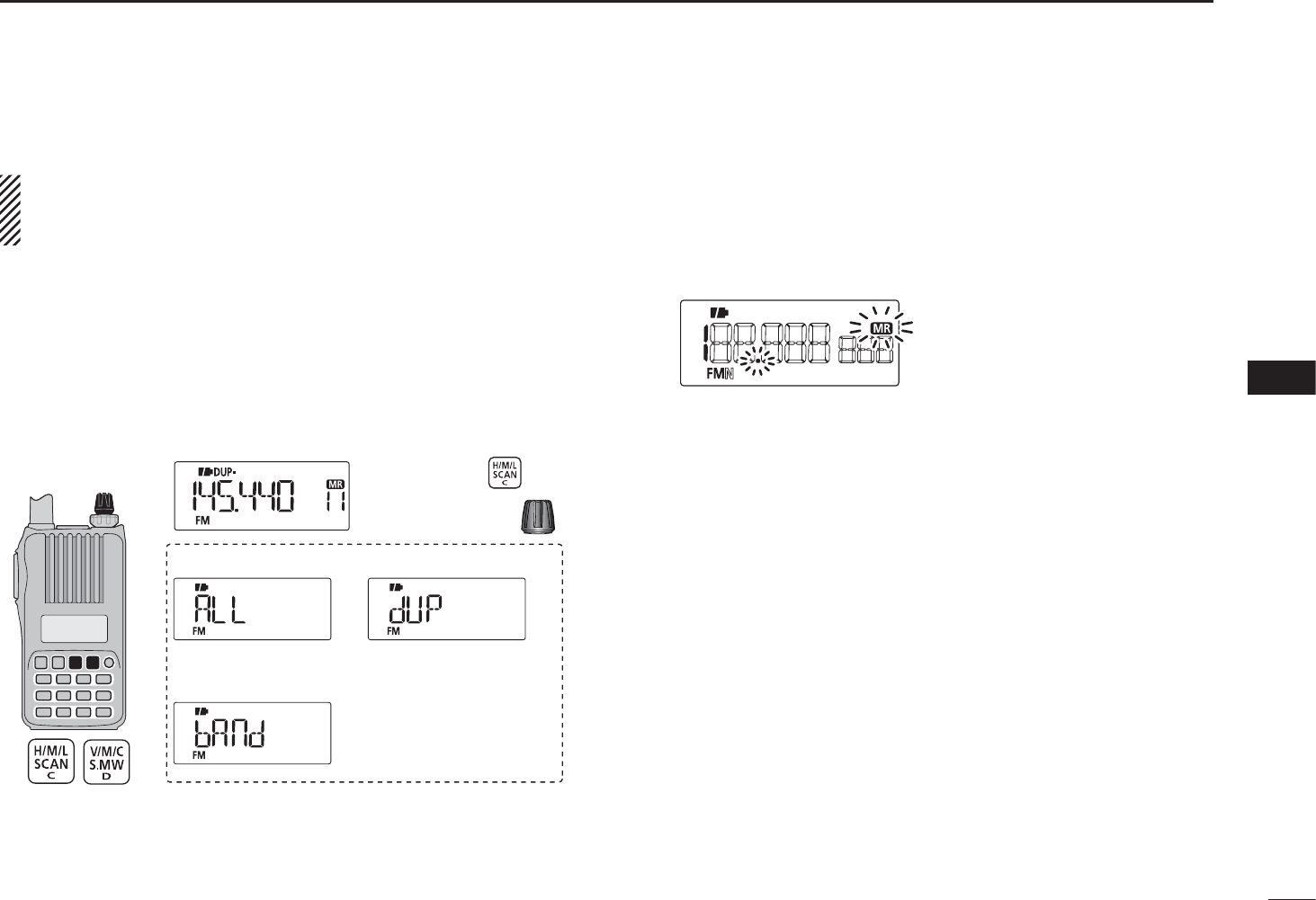
N Memory scan
IMPORTANT!: To perform memory scan, 2 or more mem-
ory channels MUST be programmed, otherwise the scan
will not start.
q Push [V/M/C] repeatedly to select the memory mode.
wSet the squelch level.
e Push and hold [SCAN](H/M/L) for 1 sec. to enter the scan-
ning type selection.
r Rotate [DIAL] to select a desired scanning type.
• “ALL” for all memory scan; “bAnd” for band memory scan, “dUP”
(appears only when duplex operation is set) for duplex scan.
[DIAL]
All memory scan
Band memory scan
Duplex scan
Push and hold
for 1 sec.
Rotate
tPush [SCAN](H/M/L) to start the scan.
• Scan pauses when a signal is received.
• Rotate [DIAL] to change the scanning direction. This also
causes the transceiver to resume scanning.
• Push [V/M/C] to stop the scan.
During memory scan
44
7
SCAN OPERATION
1
2
3
4
5
6
7
8
9
10
11
12
13
14
15
16
17
18
19
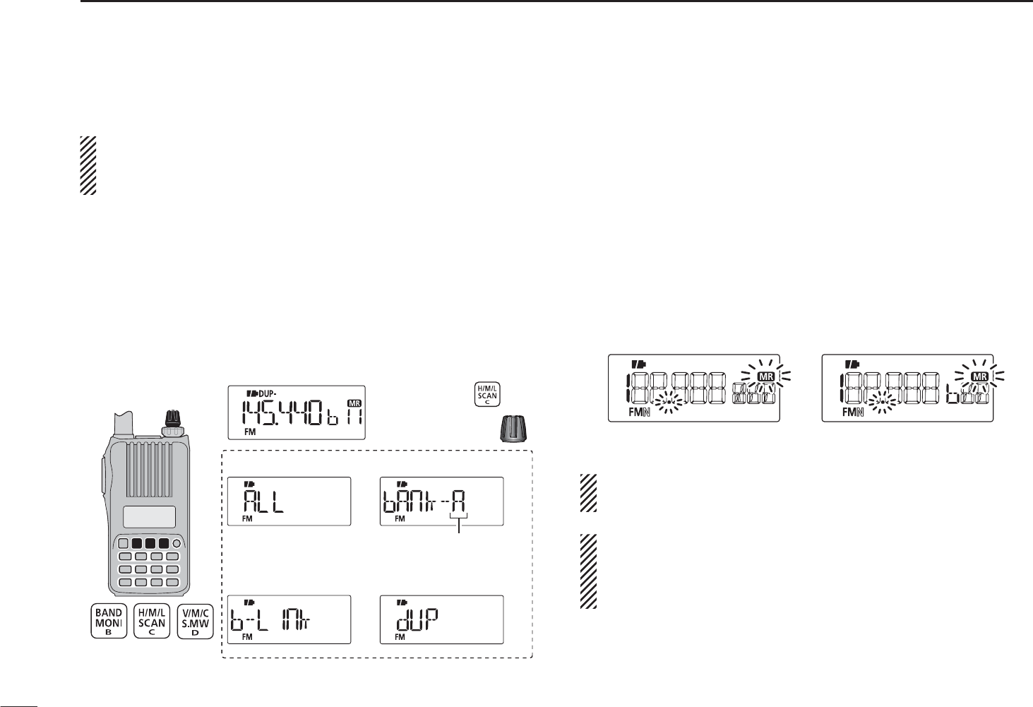
45
7SCAN OPERATION
N Memory bank scan
IMPORTANT!: To perform memory bank scan, 2 or more
bank channels MUST be programmed, otherwise the scan
will not start.
q Select memory bank mode.
±Select the memory mode with [V/M/C].
± Enter the memory bank selection mode with [BAND].
±Set a desired bank (A to Z) with [DIAL], then push
[BAND].
wSet the squelch level.
e Push and hold [SCAN](H/M/L) for 1 sec. to enter the scan-
ning type selection.
[DIAL]
All bank scan
Bank link scan
Bank scan
Duplex scan
Push and hold
for 1 sec.
Rotate
Selectable from “A” to “Z”
if programmed.
r Rotate [DIAL] to select a desired scanning type.
• “ALL” for all bank scan; “b-LInk” for bank link scan or “bAnk-x”
for bank scan (x= A to Z; programmed bank groups are only
displayed.), “dUP” (appears only when duplex operation is set)
for duplex scan.
tPush [SCAN](H/M/L) to start the scan.
• Scan pauses when a signal is received.
• Rotate [DIAL] to change the scanning direction. This also
causes the transceiver to resume scanning.
• Push [V/M/C] to stop the scan.
• Push [BAND] to change the bank during bank scan.
During all bank/bank link scan During bank scan
The bank-link setting can be changed in the Set mode.
See page 56 for details.
Memory bank scan skips any memory channels in the se-
lected bank that are set to “SKIP” or “PSKIP.”
Memory bank scan stops at the first channel when all
channels in a bank are set to “SKIP” or “PSKIP.”
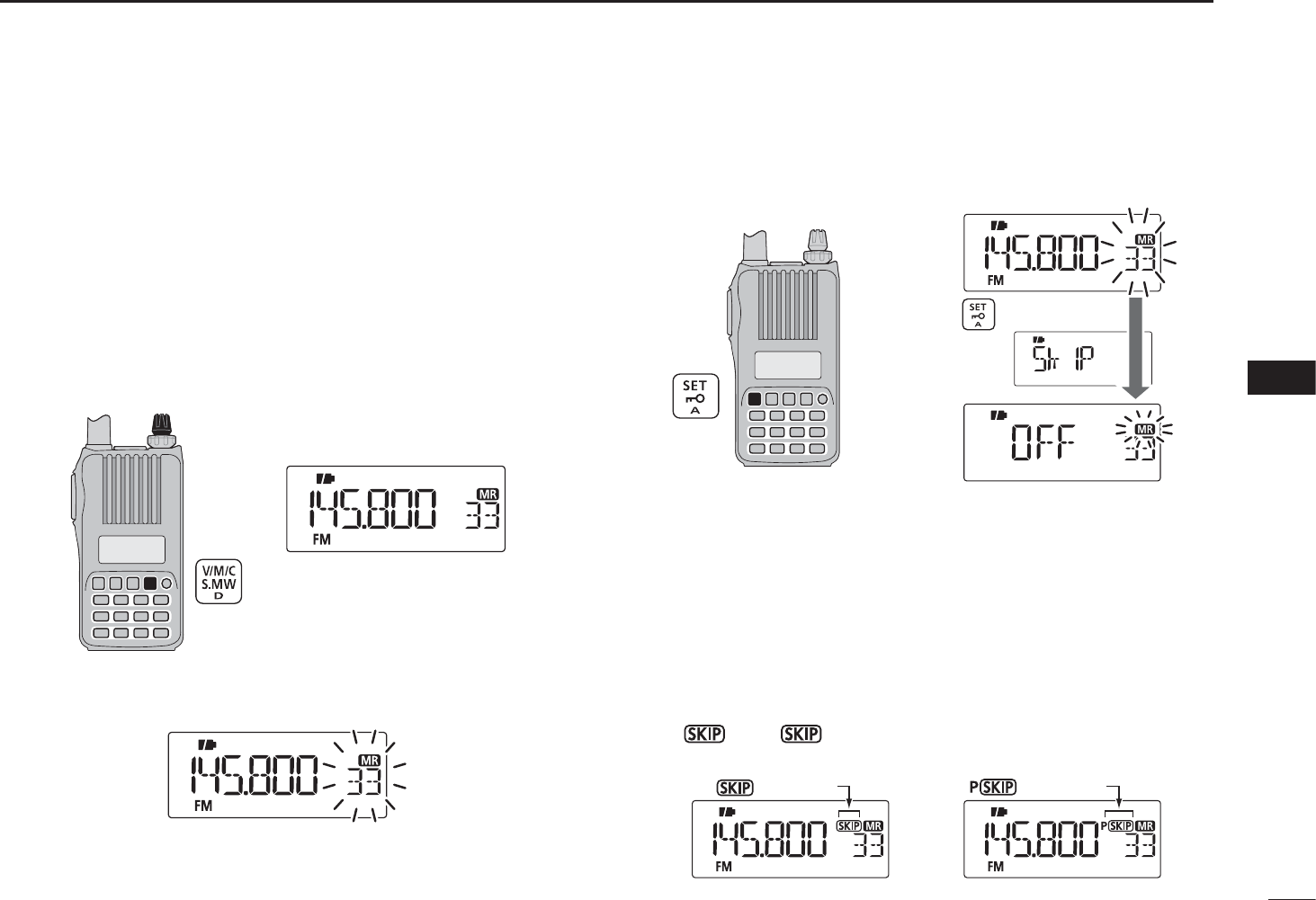
N Skip channel/frequency setting
Memory channels can be set to be skipped during memory
skip scan. In addition, memory channels can be set to be
skipped during both memory skip scan and frequency skip
scan. This is useful to speed up the scan rate.
qSelect a memory channel:
± Push [V/M/C] to select the memory mode.
±Rotate [DIAL] to select a desired channel to be a skip
channel/frequency.
[DIAL]
w Push and hold [S.MW](V/M/C) for 1 sec. to enter the select
memory write mode.
e Push [SET] repeatedly to select “SkIP” item.
Push repeatedly.
r Rotate [DIAL] to select the skip condition from “SkIP,”
“PSkIP” or “OFF” for the selected channel.
• PSkIP : The channel is skipped during memory/bank scan and
the programmed frequency is skipped during VFO scan,
such as programmed scan.
• SkIP : The channel is skipped during memory or bank scan.
• OFF : The channel is scanned during any scan.
t Push and hold [S.MW](V/M/C) for 1 sec. to store the skip
condition into the memory.
•“ ” or “P” icon appears, according to the skip selection
in step r.
“ ” appears “ ” appears
Skip channel setting Program skip setting
46
7
SCAN OPERATION
1
2
3
4
5
6
7
8
9
10
11
12
13
14
15
16
17
18
19
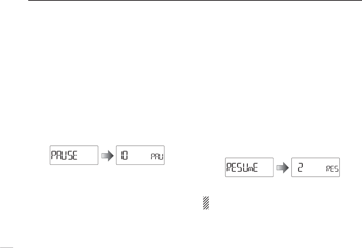
N Scan resume condition
D Scan pause timer
The scan pauses when receiving signals according to the
scan pause time. It can be set from 2 to 20 seconds or un-
limited.
q Push [SET] to enter the Set mode.
w Rotate [DIAL] to select the scan pause timer item.
e Rotate [VOL] to select a desired scan pausing time from
2–20 seconds (2 seconds steps) or “HOLd.”
• “2”–“20” : Scan pauses for 2–20 seconds while receiving a sig-
nal.
• “HOLd” : Scan pauses on a received a signal until it disap-
pears.
rPush [V/M/C] to return to the frequency display.
D Scan resume timer
The scan restarts after the signal disappears according to the
resume time. It can be set from 0–5 seconds or unlimited.
q Push [SET] to enter the Set mode.
w Rotate [DIAL] to select the scan pause timer item.
e Rotate [VOL] to select a desired scan resume time from
0–5 seconds (1 second steps) or “HOLd.”
• “0” : Scan restarts immediately after the signal disap-
pears.
• “1”–“5” : Scan restarts 1–5 seconds after the signal disap-
pears.
• “HOLd” : Scan remains paused on the received signal accord-
ing to the scan pause timer even if it disappears. Ro-
tate [DIAL] to resume manually.
rPush [V/M/C] to return to the frequency display.
Scan resume timer must be set shorter than the scan
pause timer, otherwise this timer does not activate.
47
7SCAN OPERATION
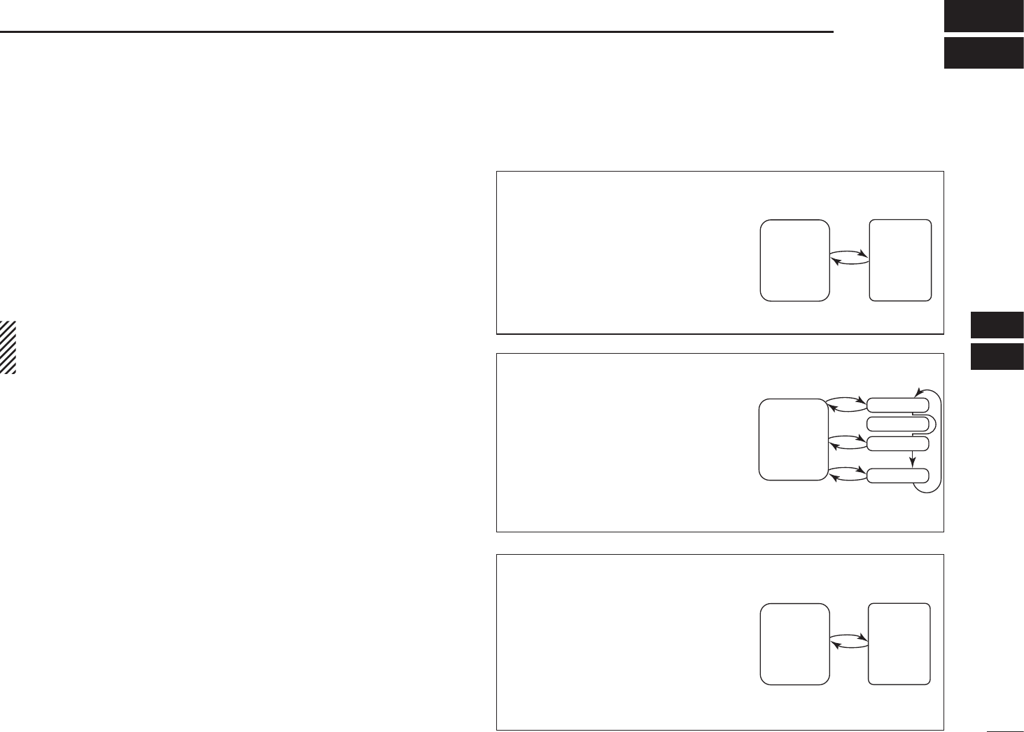
48
8
PRIORITY WATCH
1
2
3
4
5
6
7
8
9
10
11
12
13
14
15
16
17
18
19
N Priority watch types
Priority watch checks for signals on the frequency every
5 seconds while operating on a VFO frequency or scanning.
The transceiver has three priority watch types to suit your
needs.
The watch resumes according to the selected scan resume
condition. See page 47 for details.
NOTE: If the pocket beep function is activated, the trans-
ceiver automatically selects the tone squelch function
when priority watch starts.
D About priority beep function
When receiving a signal on the priority frequency, you can be
alerted with beeps and a blink “S” icon. This function can
be activated when setting the priority watch function ON.
MEMORY/CALL CHANNEL WATCH
While operating on a VFO fre-
quency, priority watch checks for
a signal on the selected channel
every 5 seconds.
• A memory channel with skip infor-
mation can be watched.
MEMORY SCAN WATCH
While operating on a VFO fre-
quency, priority watch checks
for signals on each memory
channel in sequence.
• The memory skip function and/or
memory bank scan is useful to
speed up the scan.
VFO SCAN WATCH
While scanning in the VFO
mode, priority watch checks for
signals on the selected channel
every 5 seconds.
5 sec.
VFO
frequency
Memory
(Call)
channel
5 sec.
VFO
frequency
SKIP
Mch 0
Mch 1
Mch 2
Mch 249
5 sec.
VFO
scan
Memory
(Call)
channel
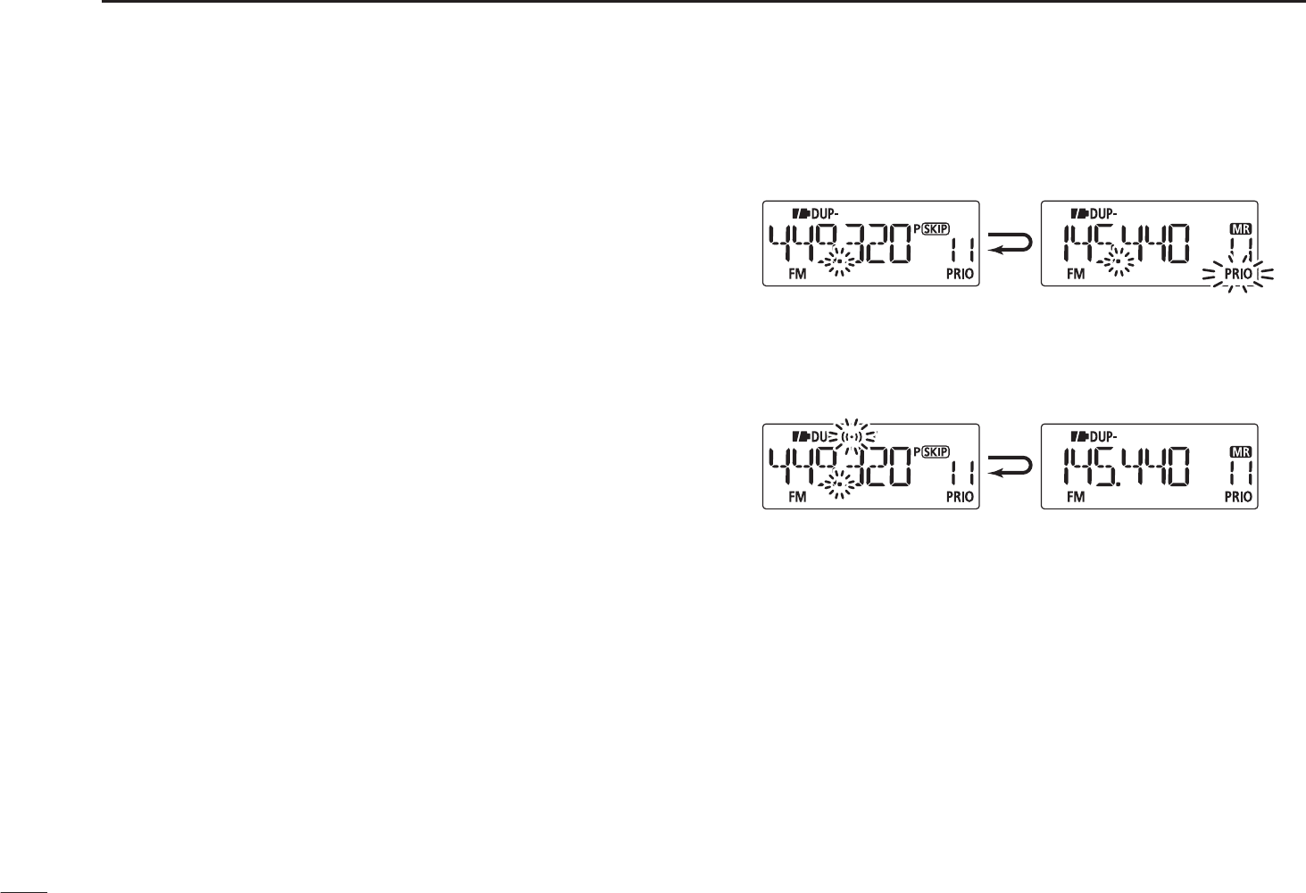
49
8PRIORITY WATCH
NPriority watch operation
DMemory/call channel and memory scan watch
qSelect the VFO mode; then, set an operating frequency.
wSelect the channel(s) to be watched.
For memory channel watch:
Select a desired memory channel.
For call channel watch:
Select a desired call channel.
For memory scan watch:
± Select the memory mode, or a desired bank group.
±Push and hold [SCAN](H/M/L) for 1 sec. to enter the
scan type selection mode.
±Rotate [DIAL] to select a desired scan type, then push
[SCAN](H/M/L) again to start the memory/bank scan.
e Push [SET] to enter the Set mode.
r Rotate [DIAL] to select the priority watch set item.
t Rotate [VOL] to select “On.”
• Select “bELL” if the priority beep function is desired.
y Push [V/M/C] to exit the Set mode and start the watch.
• “PRIO” icon appears.
• The transceiver checks the memory/bank channel(s) or call
channel every 5 seconds.
• The watch resumes according to the selected scan resume con-
dition. (p. 47)
u Push [V/M/C] to cancel the watch.
Monitors VFO frequency
for 5 sec.
Pauses on a memory
or call channel when
a signal is received.
• During priority watch
Sounds beep tone and blinks “S” icon when a signal is
received on a memory or call channel.
• During priority watch with priority beep
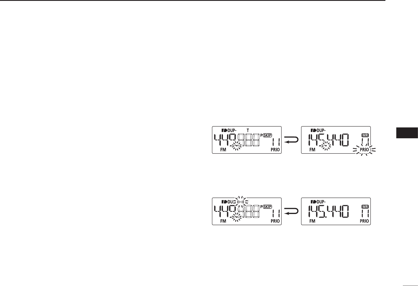
50
8
PRIORITY WATCH
1
2
3
4
5
6
7
8
9
10
11
12
13
14
15
16
17
18
19
DVFO scan watch
qSelect the channel(s) to be watched.
For memory channel watch:
Select a desired memory channel.
For call channel watch:
Select a desired call channel.
For memory scan watch:
± Select the memory mode, or a desired bank group.
±Push and hold [SCAN](H/M/L) for 1 sec. to enter the
scan type selection.
±Rotate [DIAL] to select a desired scan type, then push
[SCAN](H/M/L) again to start memory/bank scan.
w Push [SET] to enter the Set mode.
e Rotate [DIAL] to select the priority watch set item.
r Rotate [VOL] to select “On.”
• Select “bELL” if the priority beep function is desired.
t Push [V/M/C] to exit the Set mode and start the watch.
• “PRIO” icon appears.
y Push and hold [SCAN](H/M/L) for 1 sec. to enter scan type
selection mode.
u Rotate [DIAL] to select a desired scan type from “ALL,”
“bAnd,” “P-LInk x (x= 0–9),” “PROGxx (xx= 0–24)” and “dUP.”
iPush [SCAN](H/M/L) to start the VFO scan watch.
• The transceiver checks the memory/bank channel(s) or call
channel every 5 seconds.
• The watch resumes according to the selected scan resume con-
dition. (p. 47)
i Push [V/M/C] to cancel the watch.
Searches VFO frequencies
for 5 sec.
Pauses on a memory
or call channel when
a signal is received.
• During priority watch
Sounds beep tone and blinks “S” icon when a signal is
received on a memory or call channel.
• During priority watch with priority beep
51
SET MODES
9
N General
D Entering Set mode and operation
The Set mode is used to change the settings of the trans-
ceiver’s functions.
q Push [SET] to enter the Set mode.
w Rotate [DIAL] to select the desired set item.
e Rotate [VOL] to set the desired value or setting.
rPush [V/M/C] to return to frequency display, or repeat
steps w and e to set another items.
[VOL]
[DIAL]
D Entering Initial set mode and operation
The Initial set mode can be accessed at power ON and al-
lows you to set seldom-changed settings, to suit your prefer-
ence and operating style.
qWhile continuing to push [SET], turn the power ON to
enter the Initial set mode.
w Rotate [DIAL] to select the desired set item.
e Rotate [VOL] to set the desired value or setting.
rPush [] to return to the frequency display, or repeat
steps w and e to set another items.
[VOL]
[DIAL]
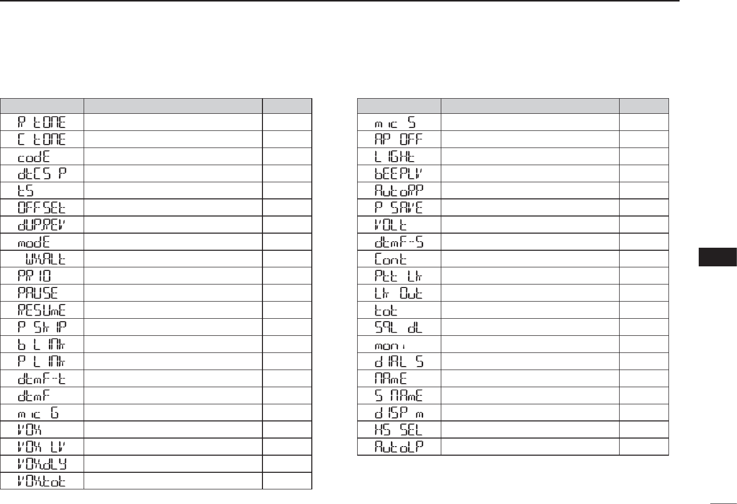
52
9
SET MODES
1
2
3
4
5
6
7
8
9
10
11
12
13
14
15
16
17
18
19
N Set mode item list
Guidance Item Page
Repeater tone frequency p. 5353
TSQL frequency p. 5353
DTCS code p. 5353
DTCS polarity p. 5353
Tuning step p. 5454
Frequency offset p. 5454
Reverse duplex function p. 5454
Operating mode p. 5454
Weather alert p. 5454
Priority watch p. 5555
Scan pause timer p. 5555
Scan resume timer p. 5555
Program skip function p. 5555
Bank link p. 5656
Programmed scan link p. 5656
DTMF TX key p. 5858
DTMF memory setting p. 5858
MIC gain p. 5858
VOX function p. 5858
VOX gain p. 5858
VOX delay p. 5959
VOX time-out timer p. 5959
N Initial set mode item list
Guidance Item Page
Microphone simple mode p. 5959
Auto power OFF p. 5959
Display backlight p. 6060
Beep output level p. 6060
Auto repeater p. 6060
Power save p. 6161
Voltage indication p. 6161
DTMF speed p. 6161
LCD contrast p. 6262
PTT lock p. 6262
Busy lockout p. 6262
Time-out timer p. 6262
Squelch delay p. 6262
Monitor key action p. 6363
Dial speed acceleration p. 6363
Memory name p. 6363
Scan name p. 6363
Display type p. 6464
HS-95 selection p. 6464
Auto low power p. 6464
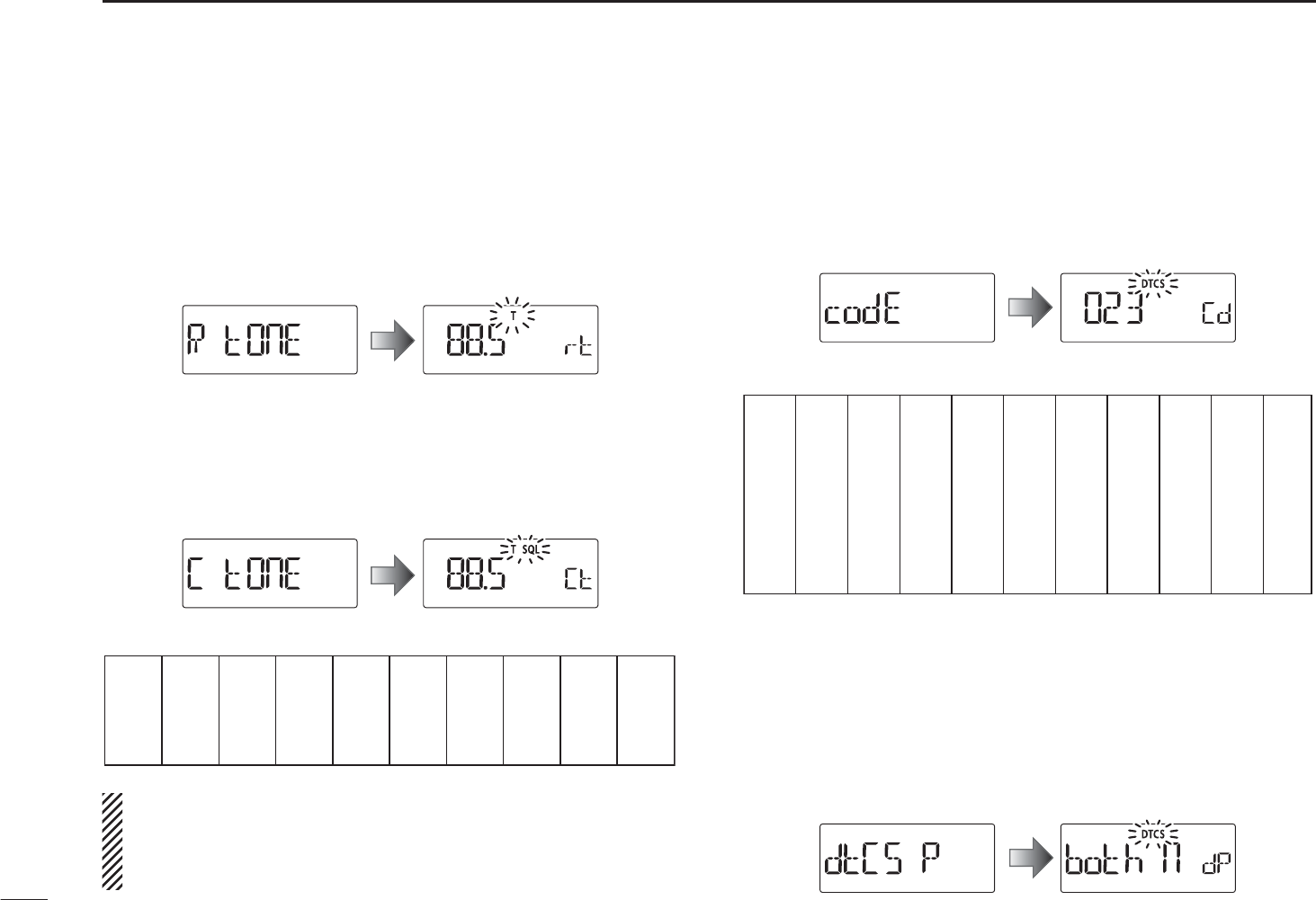
53
9SET MODES
N Set mode items
D Repeater tone frequency (R TONE)
Selects one of 50 subaudible tone frequencies used to ac-
cess the repeaters.
• 67.0–254.1 Hz (default: 88.5 Hz)
D TSQL frequency (C TONE)
Selects one of tone frequencies for tone squelch or pocket
beep operation.
• 67.0–254.1 Hz (default: 88.5 Hz)
• Available subaudible tone frequencies
67.0
69.3
71.9
74.4
77.0
79.7
82.5
85.4
88.5
91.5
94.8
97.4
100.0
103.5
107.2
110.9
114.8
118.8
123.0
127.3
131.8
136.5
141.3
146.2
151.4
156.7
159.8
162.2
165.5
167.9
171.3
173.8
177.3
179.9
183.5
186.2
189.9
192.8
196.6
199.5
203.5
206.5
210.7
218.1
225.7
229.1
233.6
241.8
250.3
254.1
The transceiver has 50 tone frequencies and conse-
quently their spacing is narrow compared with units hav-
ing 38 tones. Therefore, some tone frequencies may re-
ceive interference from adjacent tone frequencies.
DDTCS code (CODE)
Selects one of 104 DTCS (both encoder/decoder) codes.
• 023–754 (default: 023)
• Available DTCS codes
023
025
026
031
032
036
043
047
051
053
125
131
132
134
143
145
152
155
156
162
245
246
251
252
255
261
263
265
266
271
356
364
365
371
411
412
413
423
431
432
506
516
523
526
532
546
565
606
612
624
054
065
071
072
073
074
114
115
116
122
165
172
174
205
212
223
225
226
243
244
274
306
311
315
325
331
332
343
346
351
445
446
452
454
455
462
464
465
466
503
627
631
632
654
662
664
703
712
723
731
732
734
743
754
DDTCS polarity (DTCS P)
Selects the DTCS polarity between “both n” (TX/RX: normal),
“tn-RR” (TX: normal, RX: reverse), “tR-Rn” (TX: reverse, RX:
normal) and “both R” (TX/RX: reverse). (default: both n)
The DTCS code’s polarity for transmitting or receiving can
be independently set by this item.
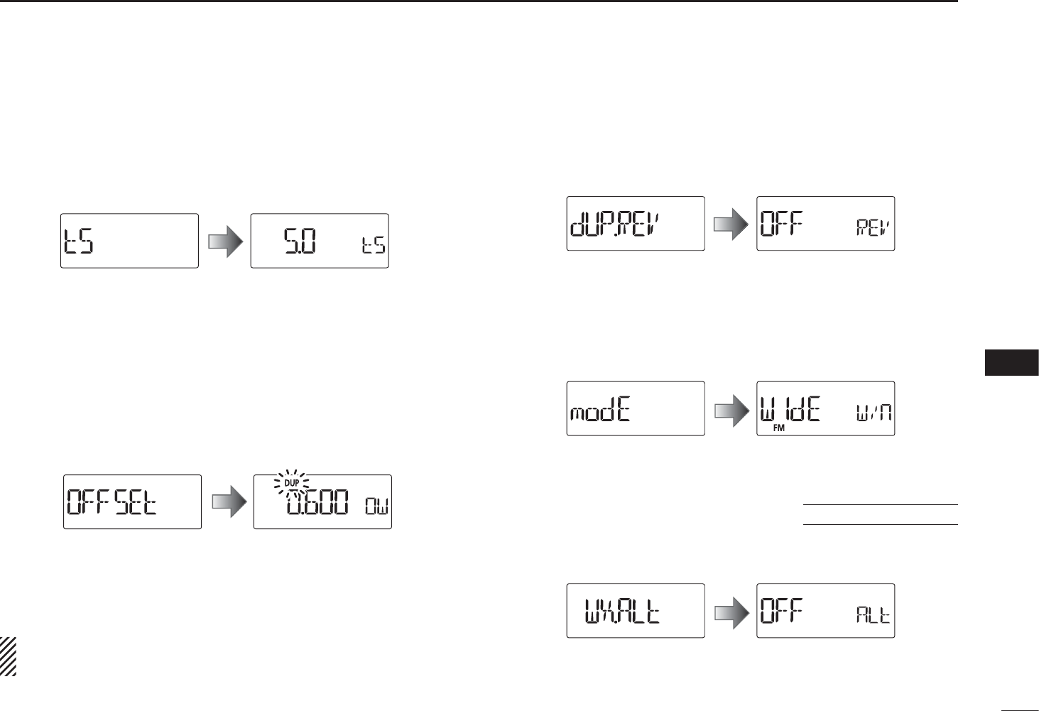
54
9
SET MODES
1
2
3
4
5
6
7
8
9
10
11
12
13
14
15
16
17
18
19
D Tuning step (TS)
Sets the tuning step between 5, 10, 12.5, 15, 20, 25, 30 and
50 kHz for the dial operation.
5.0 kHz tuning step
The default value may differ according to the selected fre-
quency band (before accessing the Set mode) and trans-
ceiver version.
D Frequency offset (OFFSET)
Sets the offset frequency for duplex (repeater) operation
within the range of 0 to 59.995 MHz.
0.600 MHz setting
The default value may differ according to the selected fre-
quency band (before accessing the Set mode) and trans-
ceiver version.
The selected tuning step in VFO mode is used when set-
ting the frequency offset.
DReverse duplex function (DUP.REV)
Turns the reverse duplex function ON or OFF. (default: OFF)
Reverse function is OFF
D Operating mode (MODE)
Sets the operating mode between “WIdE” (FM mode) and
“nARROW” (FM-N mode). (default: WIdE)
FM mode setting
U.S.A. version only
D Weather alert (WX.ALT)
Turns weather alert function ON or OFF. (p. 72)
(default: OFF)
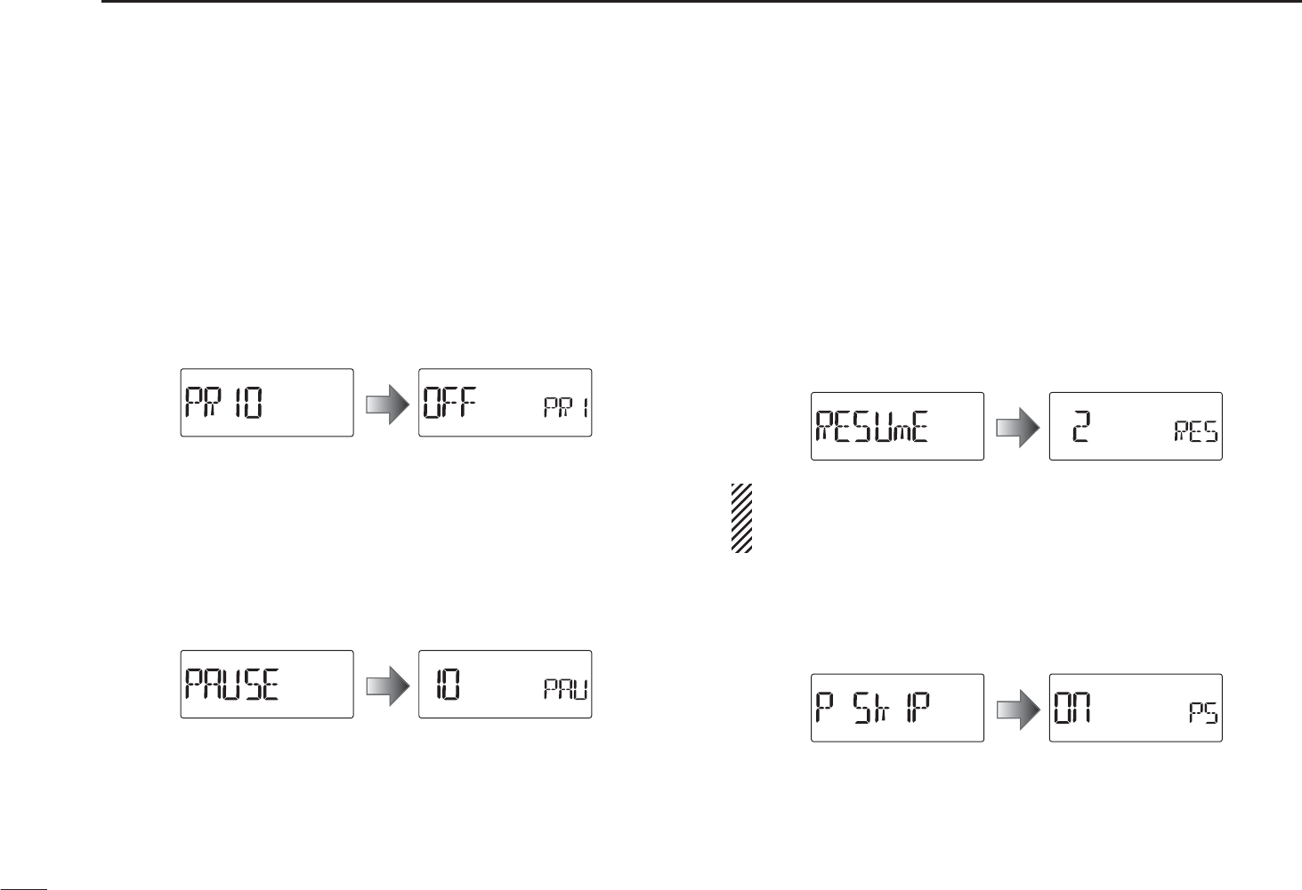
55
9SET MODES
D Priority watch (PRIO)
Activates priority watch or priority watch with alert (Bell).
(default: OFF)
• OFF : The priority watch is turned OFF.
• On : The transceiver checks the memory channel frequency
every 5 seconds.
• bELL : The transceiver checks the memory channel frequency
every 5 seconds. You can be alerted with beeps and
blinking “S.”
D Scan pause timer (PAUSE)
Selects the scan pause time. When receiving signals, the
scan pauses according to the scan pause timer. (default: 10)
• 2–20 : Scan pauses for 2–20 seconds while receiving a signal
in 2 seconds steps.
• HOLd : Scan pauses on a received signal until it disappears.
D Scan resume timer (RESUME)
Selects the scan resume time from a pause after the received
signal disappears. (default: 2)
• 0 : Scan resumes immediately after the received signal
disappears.
• 1–5 : Scan pauses 1–5 seconds after the received signal dis-
appears.
• HOLd : Scan remains paused on the received signal according
to the scan pause timer even if it disappears. Rotate
[DIAL] to resume manually.
Scan resume timer must be set shorter than scan pause
timer (previous item), otherwise this timer cannot be acti-
vated.
D Program skip scan (P SKIP)
Sets programmed skip scan function ON (default) or OFF for
VFO scan (full scan, programmed scan, etc.) operation.
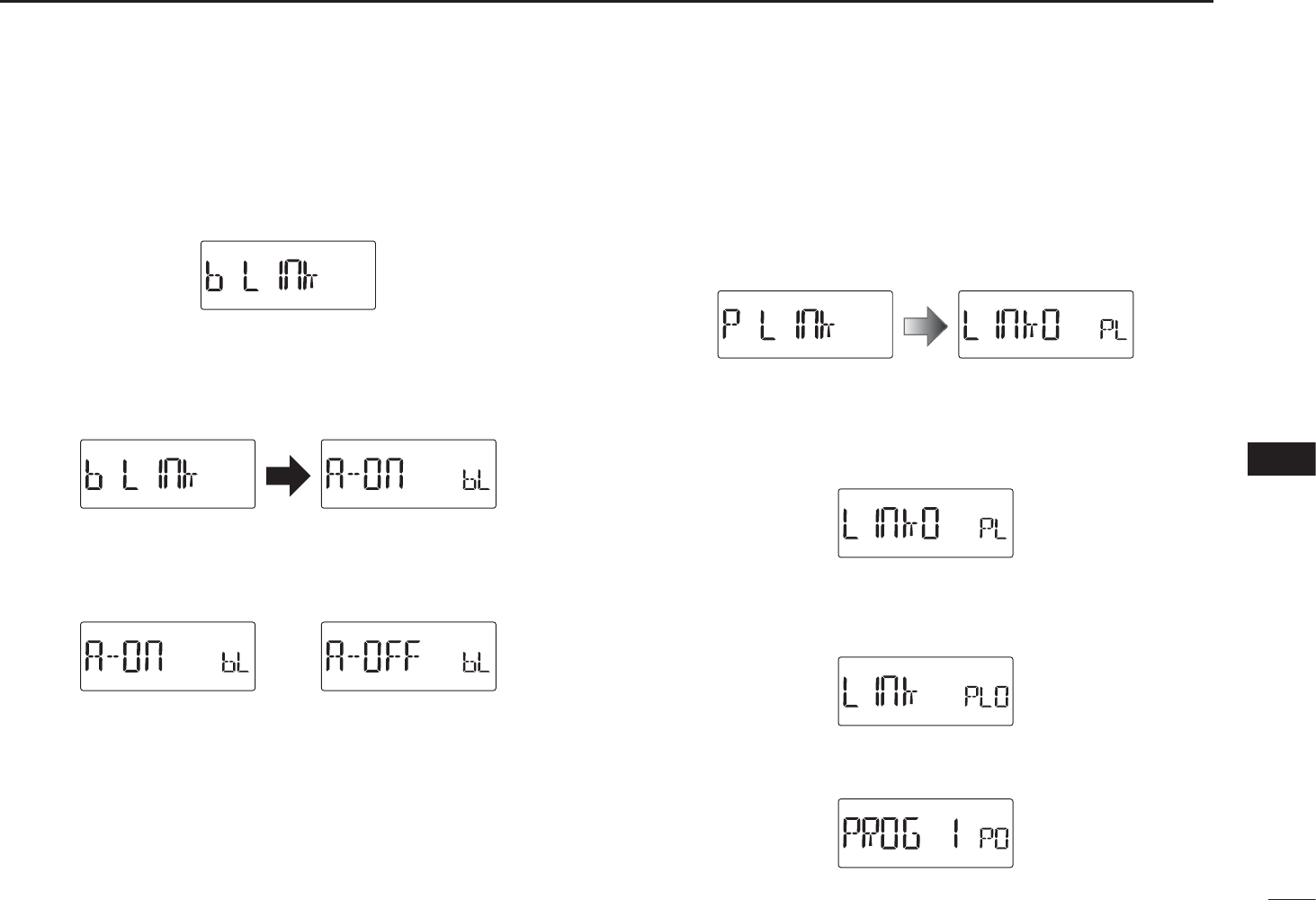
56
9
SET MODES
1
2
3
4
5
6
7
8
9
10
11
12
13
14
15
16
17
18
19
D Memory bank link function (B LINK)
Sets the memory bank link function ON (default) or OFF. The
link function provides continuous bank scan, scanning all
channels in the selected banks during bank scan.
• Bank link setting
qPush and hold [SET] for 1 sec. to enter the bank link
setting.
wRotate [DIAL] to select the bank that you want to change
the link setting.
eRotate [VOL] to select the option.
Setting is OFFSetting is ON
rRotate [DIAL] to select next bank and repeat steps w
and e, or push [BAND] to exit the BANK link setting.
D Program scan link function (P LINK)
Sets the program scan link function. The link function pro-
vides continuous program scan in the selected program scan
number during program scan.
Default settings for LInk0 to LInk9;
PROG 1 to PROG 24 are linked, but PROG 0 is no-linked.
• Confirming program scan link
qRotate [VOL] to select the program scan link number that
you want to confirm.
wPush and hold [SET] for 1 sec. to enter the program scan
link setting.
• “LInk” appears.
ePush and hold [SET] for 1 sec., then rotate [DIAL] to
confirm the linked program scans
.
rPush [BAND]
to exit the program scan link setting.
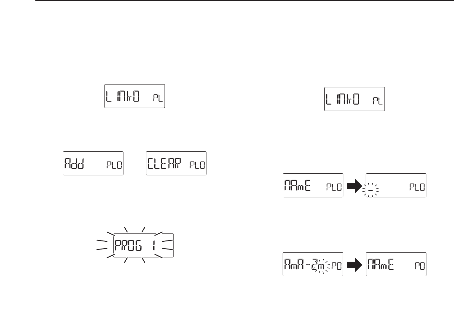
57
9SET MODES
• Program scan link setting
qRotate [VOL] to select the program scan link number that
you want to change.
wPush and hold [SET] for 1 sec. to enter the program scan
link setting.
• “LInk” appears.
eRotate [DIAL] to select the option, “Add” or “CLEAR.”
rPush and hold [SET] for 1 sec., then rotate [DIAL] to
select the desired program scan
.
• When “Add” is selected in step e, only non-linked program
scans are displayed. When “CLEAR” is selected in step e, only
linked program scans are displayed.
tPush and hold [SET] for 1 sec.
to set the program scan
link setting.
yRepeat steps r and t to add or clear the program scan
to/from the link, or push [BAND] to exit the program link
scan setting.
• Program scan link name programming
qRotate [VOL] to select the program scan link number for
which you want to program a name.
wPush and hold [SET] for 1 sec. to enter the program scan
link setting.
• “LInk” appears.
eRotate [DIAL] to select “nAmE.”
rPush and hold [SET] for 1 sec. to enter the name
programming.
t Rotate [DIAL] to select the desired character, number,
symbol or space; push [BAND] or [SET] to move the cur-
sor right or left, respectively.
y When the cursor is on the 6th digit, push [BAND] to pro-
gram the scan link name and exit the setting.
u Push [BAND] to exit the program link setting.
iRepeat steps from q to u to program the program link
scan name, or push [V/M/C] to exit the Set mode.
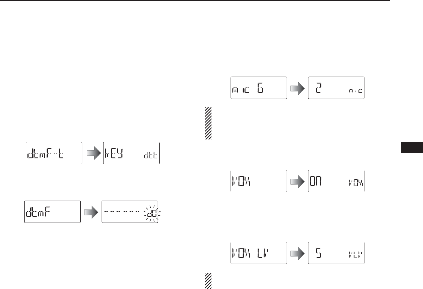
58
9
SET MODES
1
2
3
4
5
6
7
8
9
10
11
12
13
14
15
16
17
18
19
D DTMF TX key (DTMF-T)
Selects the method to transmit a DTMF code sequence.
While continueing to push [PTT], push one of the keys, [0] to
[9], [A](SET), [B](BAND), [C](H/M/L), [D](V/M/C), [1] (indica-
tion: E) and [#] (indication: F).
• KEy : Transmits the appropriate DTMF code assigned to
the key. (default)
• mEm : Transmits the programmed DTMF code sequence
in the DTMF memory channel assigned to the key.
• t-CALL : No DTMF code can be transmitted. However, while
continuing to push [PTT], push [MONI](BAND) to
transmit a 1750 Hz tone burst signal.
DDTMF memory (DTMF)
Program the DTMF memory channels. (p. 65)
DMicrophone gain (MIC G)
Sets the microphone gain to between 1 and 4 to suit your
preference. Higher values make the microphone more sensi-
tive to your voice. (default: 2)
NOTE: When using the VOX function, we recommend
setting the microphone gain to 3. However, you can adjust
it to suit your operating environment (including the head-
set performance you are using).
DVOX function (VOX) (VOX)
Turns the vox function ON or OFF. (p. 80) (default: On)
DVOX gain (VOX LV) (VOX LV)
Sets the VOX gain to between 1 and 10. Higher values make
the VOX function more sensitive to your voice.
To turn the VOX function OFF, select “OFF.” (default: 5)
NOTE: Set the microphone gain before setting the VOX
gain. See page 80 for details of the VOX function.
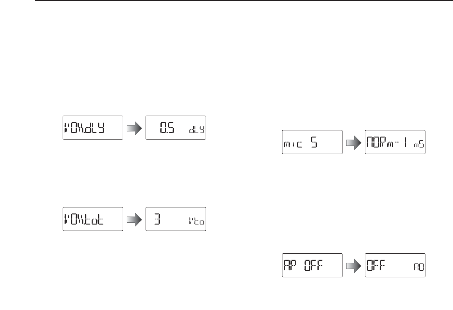
59
9SET MODES
DVOX delay (VOX.DLY)
Sets the VOX delay to between “0.5,” “1.0,” “1.5,” “2.0,” “2.5”
and “3.0” (seconds).
The VOX delay is the amount of time the transmitter stays
ON after you stop speaking. (default: 0.5)
DVOX time-out timer (VOXTOT)
Sets the VOX time-out timer to between 1, 2, 3, 4, 5, 10 and
15 (minutes) to prevent accidental prolonged transmission
for the VOX function.
To turn the function OFF, select “OFF.” (default: 3)
N Initial set mode items
D Microphone simple mode (MIC S)
Microphone simple mode is used to assign the essential op-
erations to the four switches (S1 to S4) on the remote con-
trol unit. (p. 82)
• SImPLE
• nORm-1 (default)
• nORm-2
D Auto power OFF (AP OFF)
The transceiver can turn itself OFF automatically after a
specified time. Activating a control restarts the time-out. The
transceiver beeps before turning OFF.
30, 60, 90, 120 (minutes) and OFF (default) can be specified.
The specified period is retained even when the transceiver
is turned OFF by the auto power-off function. To cancel the
function, select “OFF.”
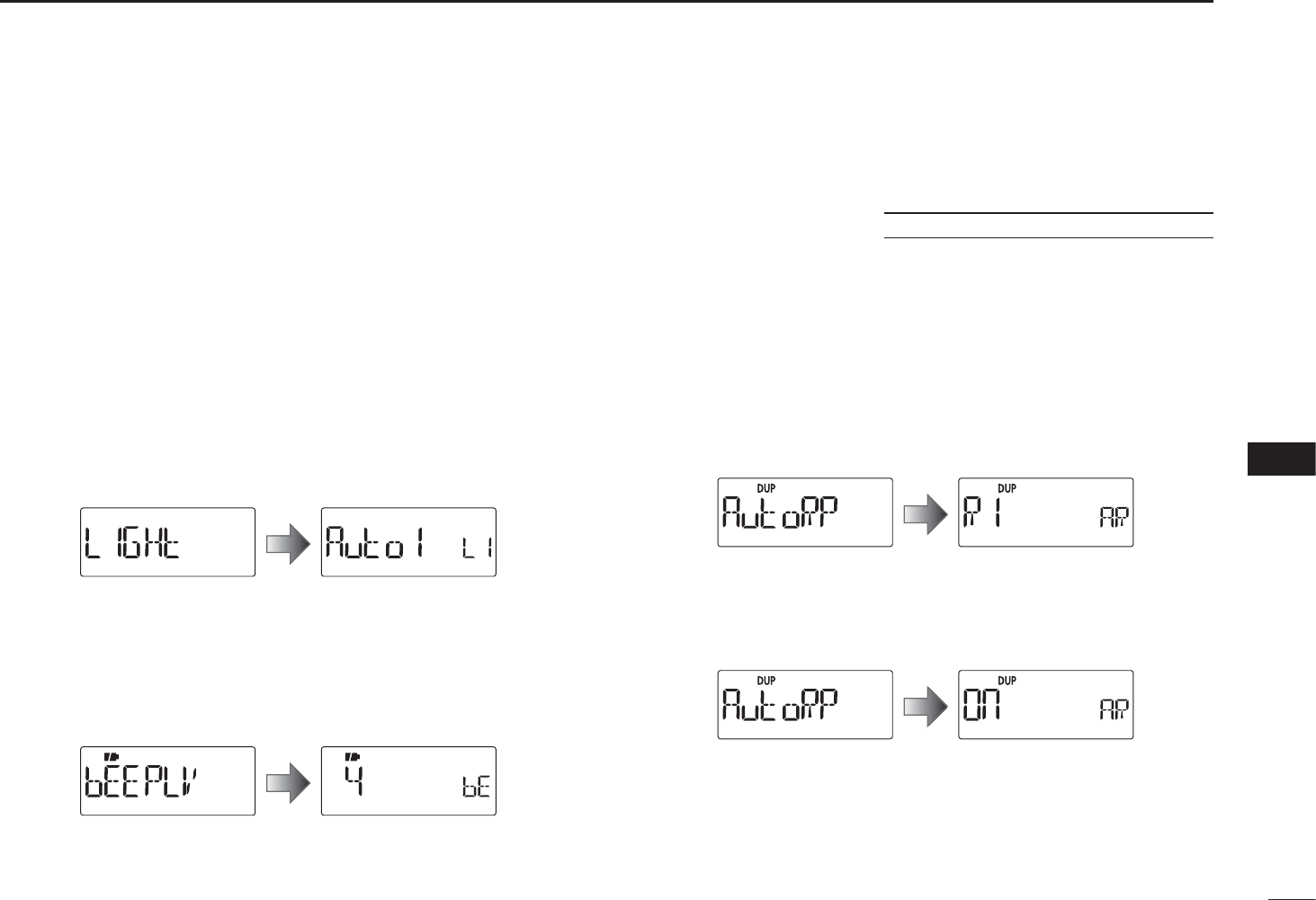
60
9
SET MODES
1
2
3
4
5
6
7
8
9
10
11
12
13
14
15
16
17
18
19
D Display backlighting (LIGHT)
The transceiver has display backlighting with a 5 seconds
timer for night time operation. The display backlighting can be
turned ON continuously or turned OFF. (default: Auto1)
• OFF : The backlight is turned OFF.
• On : The backlight continuously lights ON.
• Auto1 : Lights when an operation is performed, goes out after
5 seconds.
• Auto2 : Lights when an operation is performed, goes out after
5 sec with a battery pack or battery case operation,
or stays ON when using the external power supply
(more than 10 V DC).
D Beep output level (BEEPLV)
Turns the key-touch beep ON (the beep level 1 to 9) or OFF.
When changing the beep level, beeps sound at the level.
(default: 4)
D Auto repeater (AUTORP)
U.S.A. and Korean versions only
The auto repeater function automatically turns ON or OFF the
duplex operation and tone encoder. The offset and repeater
tone settings are not changed by the auto repeater function.
Reset these frequencies, if necessary.
U.S.A. version:
• OFF : The auto repeater function is turned OFF.
• R1 : Activates for duplex only. (default)
• R2 : Activates for duplex and tone.
Korean version:
• OFF : The auto repeater function is turned OFF.
• On : Activates duplex and tone. (default)
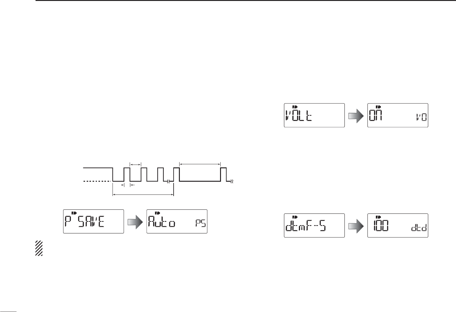
61
9SET MODES
D Power save (P SAVE)
The power save function allows you conserve battery life by
selecting the duty cycle of the receiver. Select the ratio of the
power save time to the standby time. (default: Auto)
• OFF : Turns the function OFF.
• 2 : Sets the duty cycle to 1:2.
• 8 : Sets the duty cycle to 1:8.
• 16 : Sets the duty cycle to 1:16.
• 32 : Sets the duty cycle to 1:32.
• Auto : Transceiver sets “1:2” duty ratio when receiving nosets “1:2” duty ratio when receiving no
signal for 5 seconds, then it sets “1:16” after 60 sec-
onds has past.
62.5 msec.
60 sec.
125 msec. 1000 msec.
No signal
5 sec.
Circuit ON
Circuit OFF
NOTE: Power save function is disabled when connecting
the external power supply (more than 10 V DC).
D Voltage indication (VOLT)
The power voltage, battery voltage or external power supply
voltage, is displayed at power ON. This setting is selectable
from ON or OFF. (default: On)
• OFF : The power voltage indication is skipped.
• On : The power voltage is displayed at power ON.
D DTMF speed (DTMF-S)
Select the desired DTMF transmission speed from 100 msec,
200 msec, 300 msec, 500 msec. (default: 100)
• 100 : 100 msec. interval; 5.0 characters per second
• 200 : 200 msec. interval; 2.5 characters per second
• 300 : 300 msec. interval; 1.6 characters per second
• 500 : 500 msec. interval; 1.0 character per second
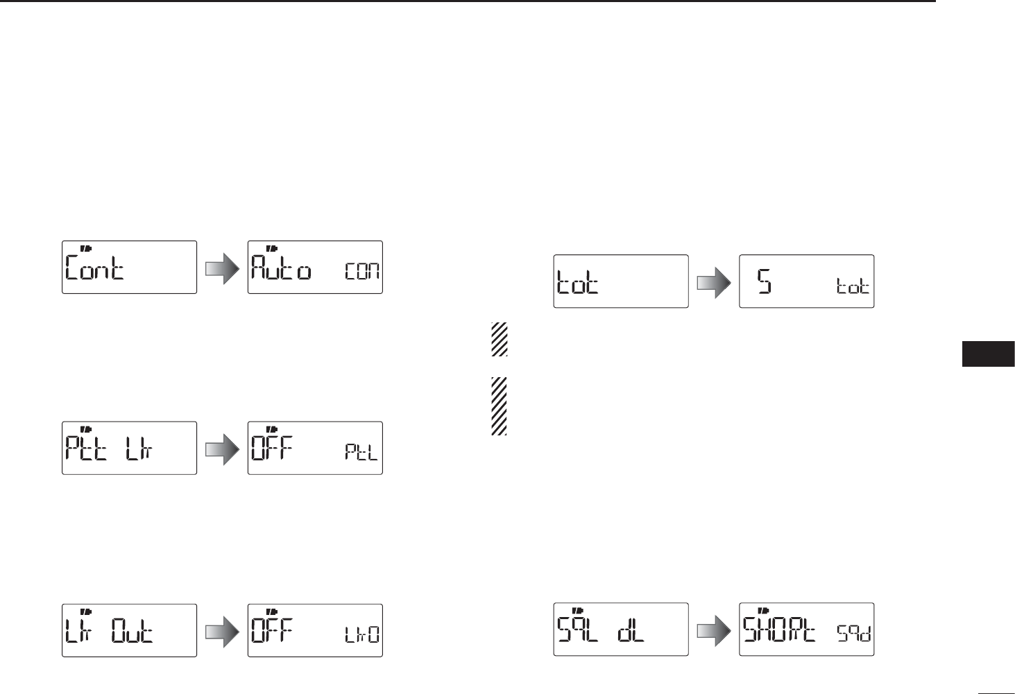
62
9
SET MODES
1
2
3
4
5
6
7
8
9
10
11
12
13
14
15
16
17
18
19
D LCD contrast (CONT)
Selects the LCD contrast. (default: Auto)
• Auto : Sets the contrast to high. However, if the transceiver is
exposed to high temperatures, it automatically sets the
contrast to low.
• HI : Sets the contrast to high.
• LO : Sets the contrast to low.
DPTT lock (PTT LK)PTT lock (PTT LK)
Turns the PTT lock function ON or OFF.
To prevent accidental transmission, etc., the transceiver has
a PTT lock function. (default: OFF)
D Busy lockout (LK OUT)
Turns the busy lockout function ON and OFF.
This function inhibits transmission while receiving a signal or
when the squelch is open. (default: OFF)
D Time-out timer (TOT)
To prevent accidental prolonged transmission, etc., the trans-
ceiver has a time-out timer. This function cuts transmission
OFF after 1–30 min. of continuous transmission. This timer
can be cancelled. (default: 5)
• OFF : The time-out timer is turned OFF.
• 1 to 30 : The transmission is cut OFF after the set period
elapses.
Approx. 10 seconds before the time-out timer is activated,
the transceiver emits a beep tone as a warning.
BE CAREFUL! The transceiver will become hot when this
time-out timer function is turned OFF or set to the long
periods, and transmission is made for long periods.
DSquelch delay (SQL DL)
Sets the squelch delay between short and long. The delay
prevents the squelch from repeatedly opening and closing
while receiving the same signal. (default: SHORt)
• SHORt : Sets the squelch delay to short.
• LOnG : Sets the squelch delay to long
.
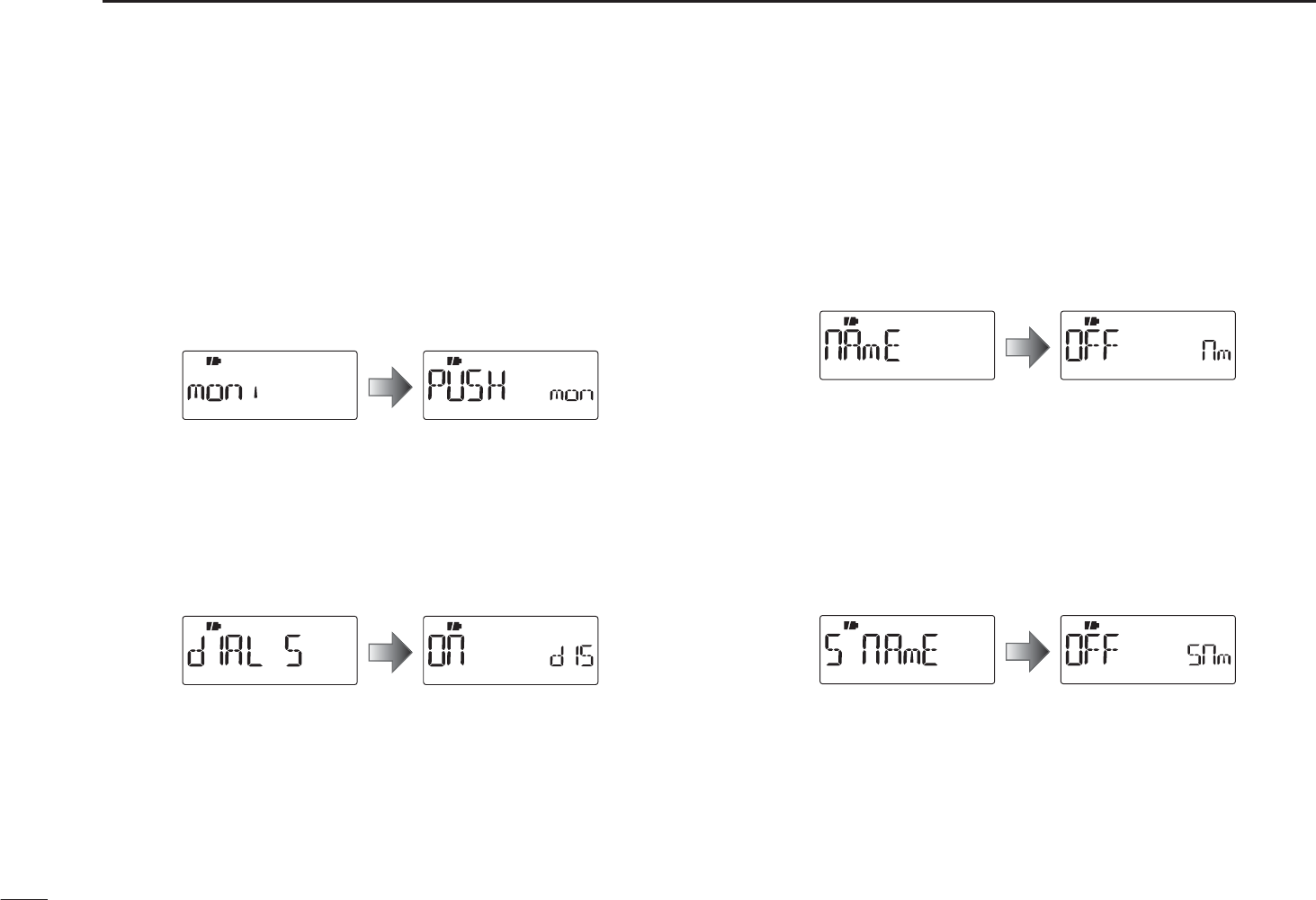
63
9SET MODES
D Monitor key action (MONI)
The monitor key, [MONI](BAND), can be set as a ‘sticky’ key.
When set to the sticky condition, each push of [MONI](BAND)
toggles the monitor function ON and OFF. (default: PUSH)
• PUSH : Push and hold [MONI](BAND) to monitor the fre-
quency.
• HOLd : Push and hold
[MONI](BAND)
for 1 sec. to monitor the
frequency and push again to cancel it.
D Dial speed acceleration (DIAL S)
The dial speed acceleration automatically speeds up the tun-
ing dial speed when rotating [DIAL] rapidly. (default: On)
• OFF : The dial speed acceleration is turned OFF.
• On : The dial speed acceleration is tuned ON.
D Memory name (NAME)
The memory name is displayed during memory mode.
(default: OFF)
• OFF : The frequency of the selected memory channel is dis-
played.
• On : The pre-programmed memory name is displayed
when the memory mode is selected.
D Scan name (S NAME)
The programmed scan, programmed link scan or bank name
is displayed during the scan type selection. (default: On)
• OFF : The programmed scan, programmed link scan or bank
name is not displayed.
• On : The programmed scan, programmed link scan or bank
name is displayed.
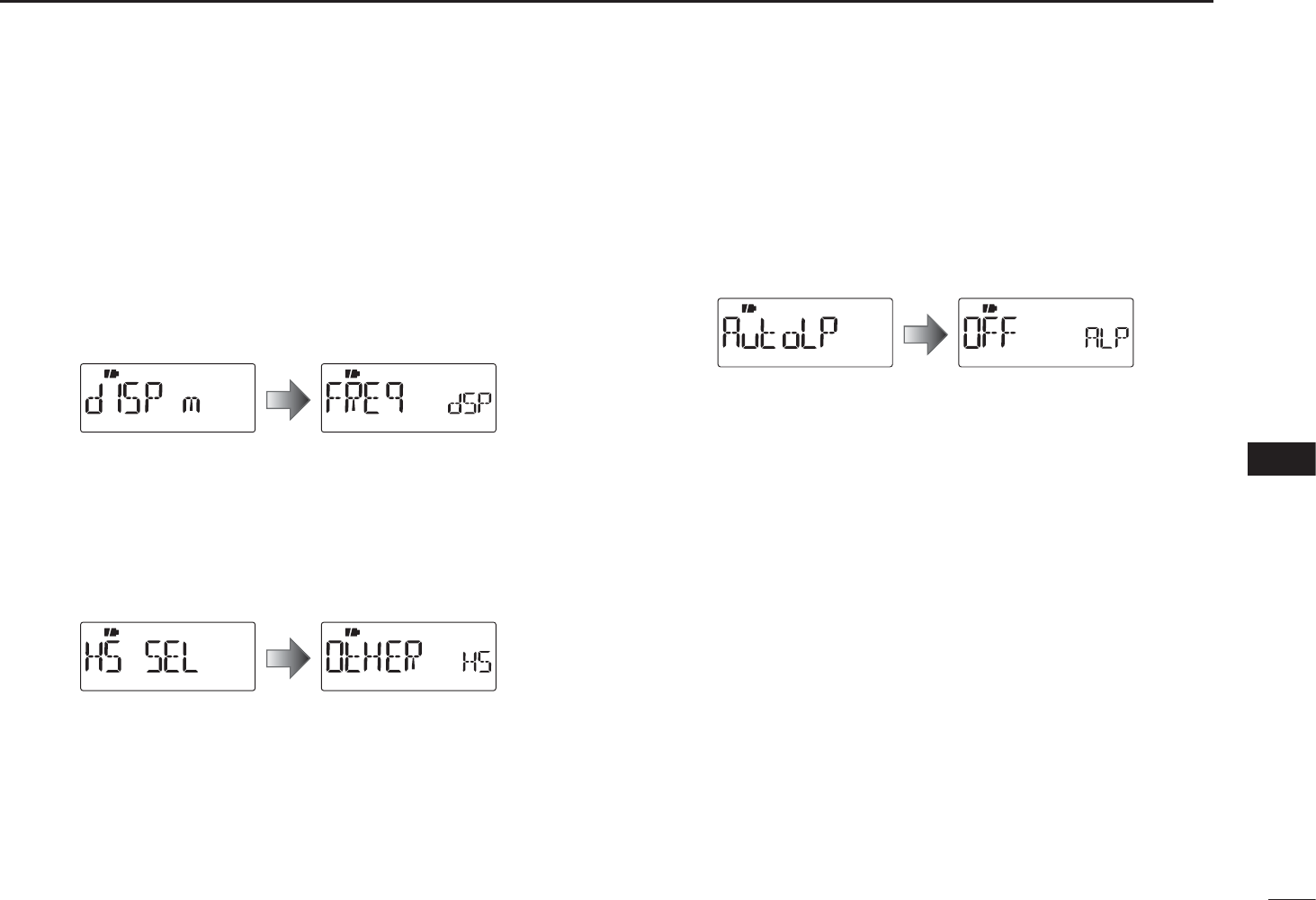
64
9
SET MODES
1
2
3
4
5
6
7
8
9
10
11
12
13
14
15
16
17
18
19
D Display type (DISP M)
Selects the display type for memory mode operation.
(default: FREq)
• FREq : Displays the programmed frequency.
•CH :
Displays the memory channel number. Operable func-
tions, configurable items in the Set mode, and select-
able modes will be restricted.
• PRIV :
Displays the memory channel number. Operable chan-
nel, functions and selectable mode are restricted.
D Head set selection (HS SEL)
Selects the connected head set type between the HS-95 and
other.
When using optional head set HS-95, this setting must be set
“HS-95.” (default: OtHER)
DAuto low power (AUTOLP)
Turns the auto low power function ON or OFF.
When the temperature goes below 0°C (+32°F), the function
automatically sets the output power to low.
In that case, the transmit power selections (Hi/Mid) are also
disabled. (default: OFF)
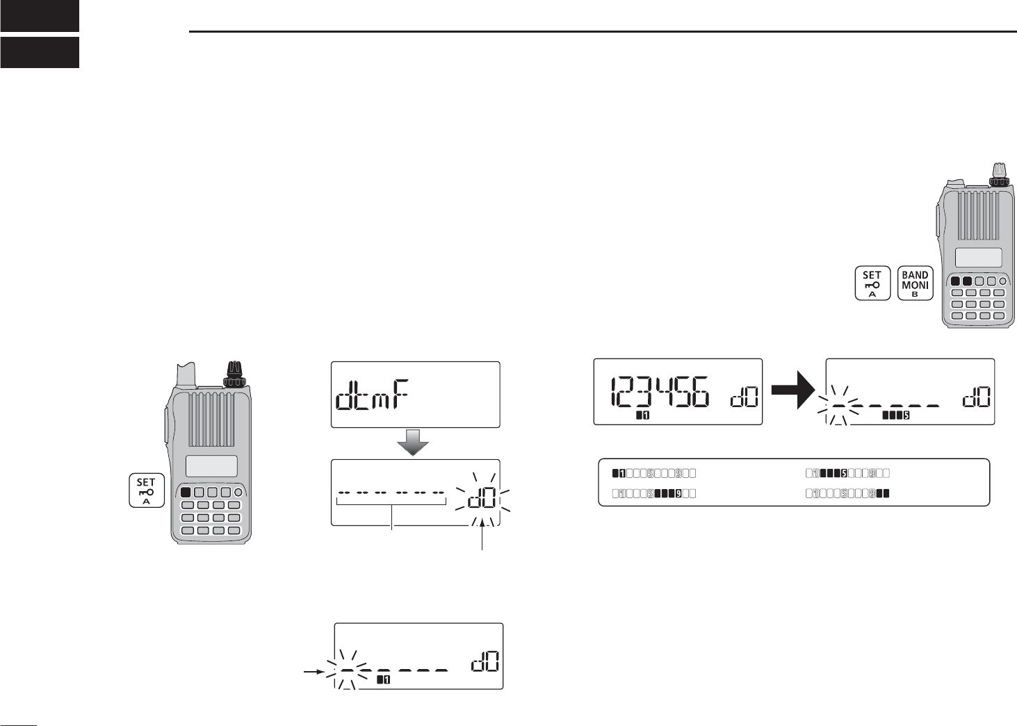
65
OTHER FUNCTIONS
10
DTMF codes are used for autopatching, accessing repeat-
ers, controlling other equipment, etc. The transceiver has 16
DTMF memory channels (d0–d9, dA, db, dC, dd, dE, dF) for
storage of often-used DTMF codes of up to 24 digits.
q Push [SET] to enter the Set mode.
w Rotate [DIAL] to select the DTMF programming item.
e Rotate [VOL] to select a desired DTMF memory channel.
• If programmed, previously programmed DTMF code is dis-
played.
[VOL]
[DIAL]
DTMF memory channel
Blank channel indication
r Push and hold [SET] for 1 sec. to enter the programming
mode.
The cursor is blinking during
programming mode.
t Rotate [VOL] to select the char-
acters.
• “0”–“9,” “A,” “b,” “C,” “d,” “E” and “F”
are selectable.
• Up to 24 digits can be programmed.
• Push [BAND] to move the cursor
right; push [SET] to move the cur-
sor left.
y Repeat step t until the desired code is input.
Next display appears after 6th digit has been input.
: 1st display : 2nd display
: 3rd display : 4th display
• If a digit is mistakenly programmed, push [SET] (or [BAND]) re-
peatedly to select the digit, then rotate [VOL] to correct it.
Or rotate [VOL] to select “_” to erase on and after the digits. Pro-
grammed memories will be cleared by this operation on the 1st
digit.
y Push [BAND] twice to program the DTMF code and exit
the programming mode.
• After the 24th digit is input, the transceiver automatically stores
the code sequence and returns to step e.
uPush [V/M/C] to return to the frequency display.
N Programming a DTMF code sequence
[VOL]
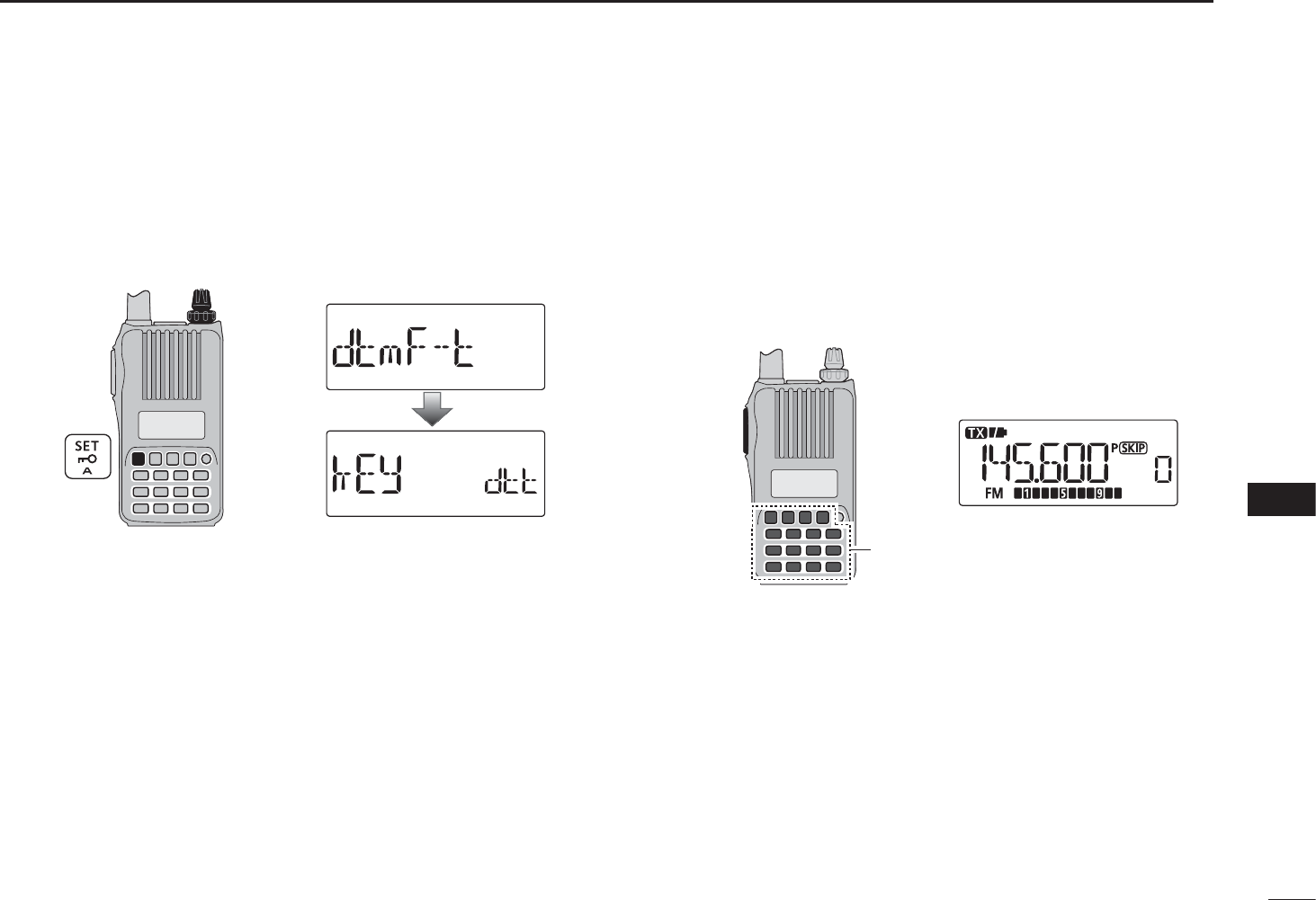
66
10
OTHER FUNCTIONS
1
2
3
4
5
6
7
8
9
10
11
12
13
14
15
16
17
18
19
The transceiver has 3 methods of transmitting a DTMF code
sequence. Select a desired option in the Set mode.
q Push [SET] to enter the Set mode.
w Rotate [DIAL] to select the DTMF TX key item.
[VOL]
[DIAL]
e Rotate [VOL] to select a desired DTMF key setting.
• kEy : Transmits the appropriate DTMF code assigned to the
pushed key. (default)
• mEm :
Transmits the programmed DTMF code sequence in the
DTMF memory channel assigned to the pushed key.
• t-CALL : No DTMF code can be transmitted. However, while
continuing to push [PTT], pushing [MONI](BAND)
transmits a 1750 Hz tone burst signal.
rPush [V/M/C] to return to the frequency display.
DManual DTMF code transmission
First, set the DTMF TX key to
“kEy” in the Set mode.
±While continuing to push [PTT], push the desired keys to
transmit a DTMF code sequence manually.
•[0]–[9],[A](SET), [B](BAND), [C](H/M/L), [D](V/M/C), [1](.) or
[#] sends “0”–“9,” “A,” “B,” “C,” “D,” “” or “#.”
[PTT]
DTMF code keys
N Transmitting a DTMF code sequence
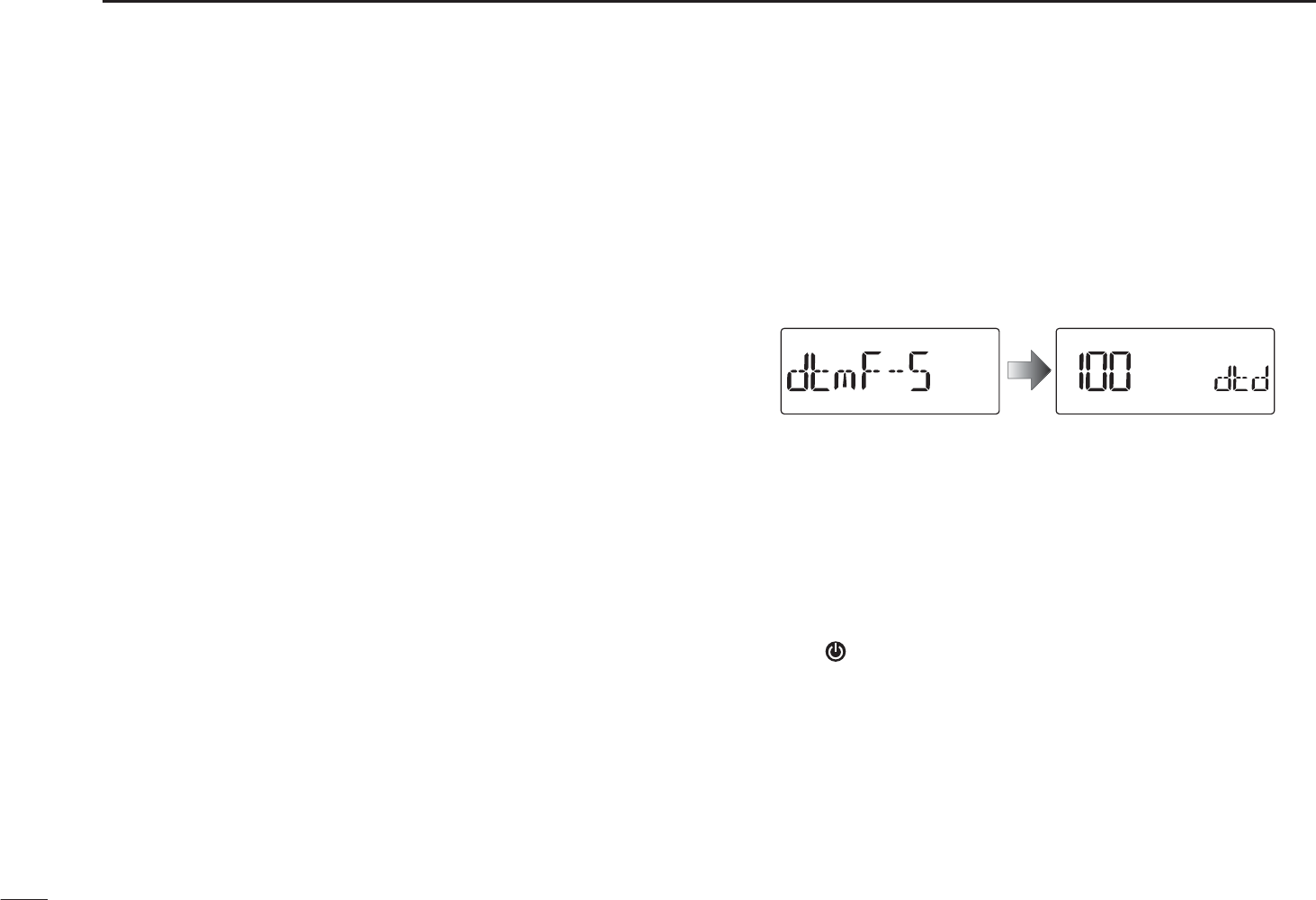
NTransmitting a DTMF code sequence (continued)
DUsing a DTMF memory channel
First, set the DTMF TX key to
“mEm” in the Set mode.
±While continuing to push [PTT], push one of the keys to
transmit the programmed DTMF code sequence in the
DTMF memory.
• Pushing [0] to [9], [A](SET), [B](BAND), [C](H/M/L),
[D](V/M/C),
[
M
]
(.) or
[
#
]
transmits “d0”–“d9,” “dA,” “db,” “dC,”
“dd,” “dE” or “dF.”
D1750 Hz tone
To access some European repeaters, the transceiver must
transmit a 1750 Hz tone burst signal.
• This tone can be used as a ‘Call signal’ in countries out of Europe.
First, set the DTMF TX key to
“t-CALL” in the Set mode.
±While continuing to push [PTT], push and hold [MONI]
(BAND) for 1 or 2 sec. to transmit a 1750 Hz tone burst
signal.
N Setting DTMF transfer speed
The DTMF transfer speed can be selected.
q While continuing to push [SET], turn the power ON to
enter the Initial set mode.
w Rotate [DIAL] to select the DTMF transfer speed item,
then rotate [VOL] to select the transfer speed.
100 : Transfer the DTMF tones at about 100 msec. per
tone.
200 : Transfer the DTMF tones at about 200 msec per
tone.
300 : Transfer the DTMF tones at about 300 msec per
tone.
500 : Transfer the DTMF tones at about 500 msec per
tone.
e Push [] to return to the frequency display.
67
10 OTHER FUNCTIONS
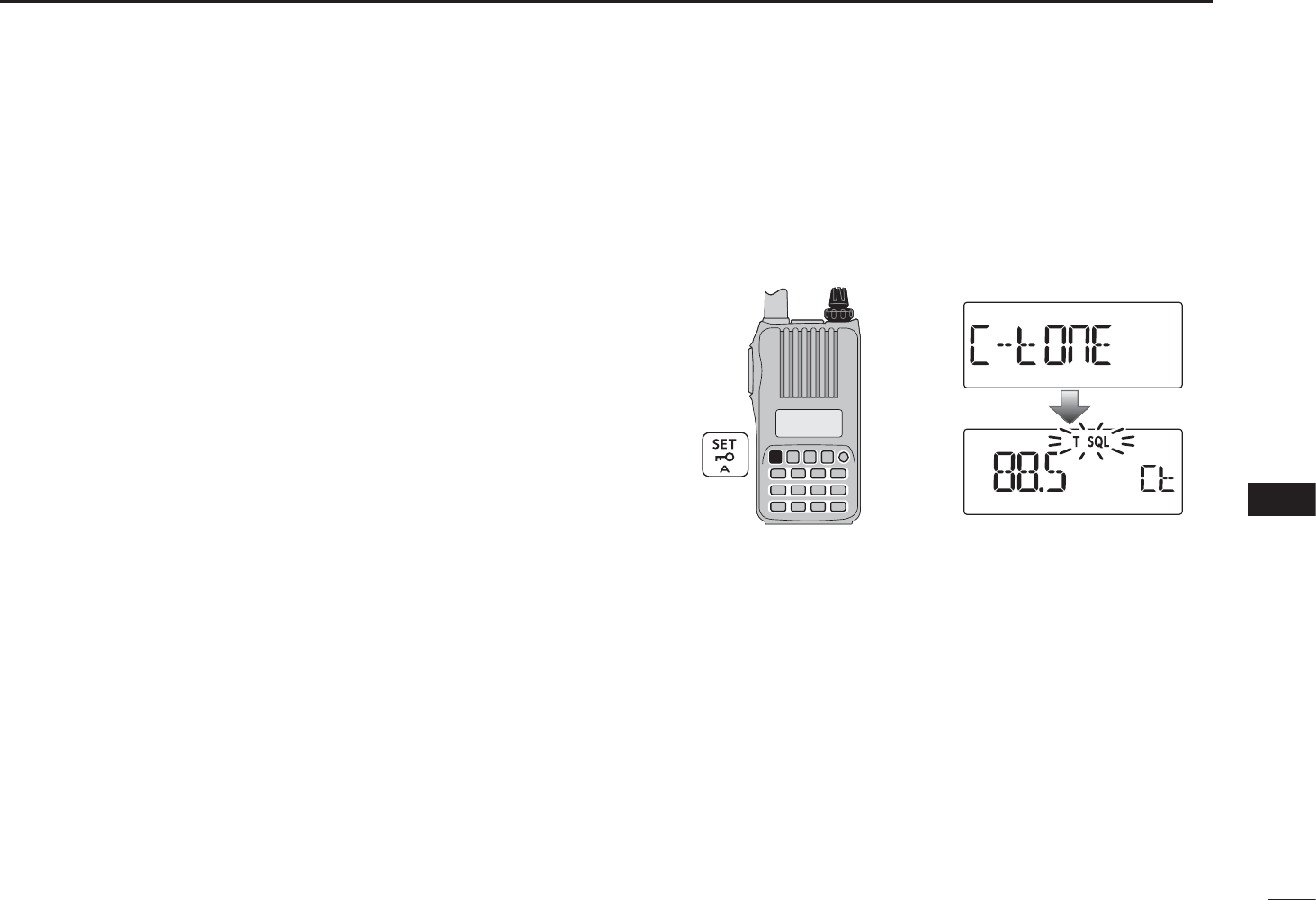
68
10
OTHER FUNCTIONS
1
2
3
4
5
6
7
8
9
10
11
12
13
14
15
16
17
18
19
NTone frequency and DTCS code
DTone and DTCS squelches
The tone squelch (CTCSS) or DTCS squelch opens only
when receiving a signal containing a matching subaudible
tone or DTCS code, respectively. You can silently wait for
calls from group members using the same tone or code.
Separate tone frequencies can be set for repeater and tone
squelch/pocket beep operation.
DReverse tone/DTCS squelch
The reverse tone/DTCS squelch is convenient if you want to
ignore a specific signal. The transceiver mutes the squelch
when a signal with the matched tone or code is received.
“T SQL-R” / “DTCS-R” is displayed when the reverse tone/
DTCS squelch is set.
DPocket beep
These functions use subaudible tones or DTCS codes for
calling and can be used as a “common pager” to inform
you that someone has called while you were away from the
transceiver.
DSetting subaudible tones for tone squelch
q Push [SET] to enter the Set mode.
w Rotate [DIAL] to select the CTCSS tone frequency item.
[VOL]
[DIAL]
e Rotate [VOL] to select a desired CTCSS tone frequency.
• Each operating band and each memory channel have indepen-
dent settings.
• See page 53 for available tone frequencies for details.
rPush [V/M/C] to return to the frequency display.
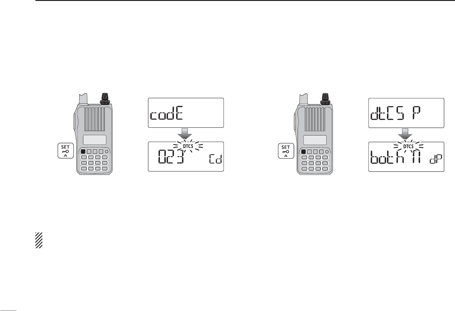
NTone frequency and DTCS code (continued)
DSetting DTCS code for DTCS squelch
q Push [SET] to enter the Set mode.
w Rotate [DIAL] to select the DTCS code item.
[VOL]
[DIAL]
e Rotate [VOL] to select a desired DTCS code.
• Each operating band and each memory channel have indepen-
dent settings.
• See page 53 for available DTCS codes for details.
rPush [V/M/C] to return to the frequency display.
DTCS phase can be selected in “dtCS-P” item. See next
content for more details.
DSetting DTCS polarity
q Push [SET] to enter the Set mode.
w Rotate [DIAL] to select the DTCS polarity item.
[VOL]
[DIAL]
e Rotate [VOL] to select a desired DTCS polarity mode.
• bOtH n : Normal phase is used for both TX and RX. (Default)
• tn-RR : Normal phase is used for TX; Reverse phase for RX.
• tR-Rn : Reverse phase is used for TX; Normal phase for RX.
• bOtH R : Reverse phase is used for both TX and RX.
rPush [V/M/C] to return to the frequency display.
69
10 OTHER FUNCTIONS
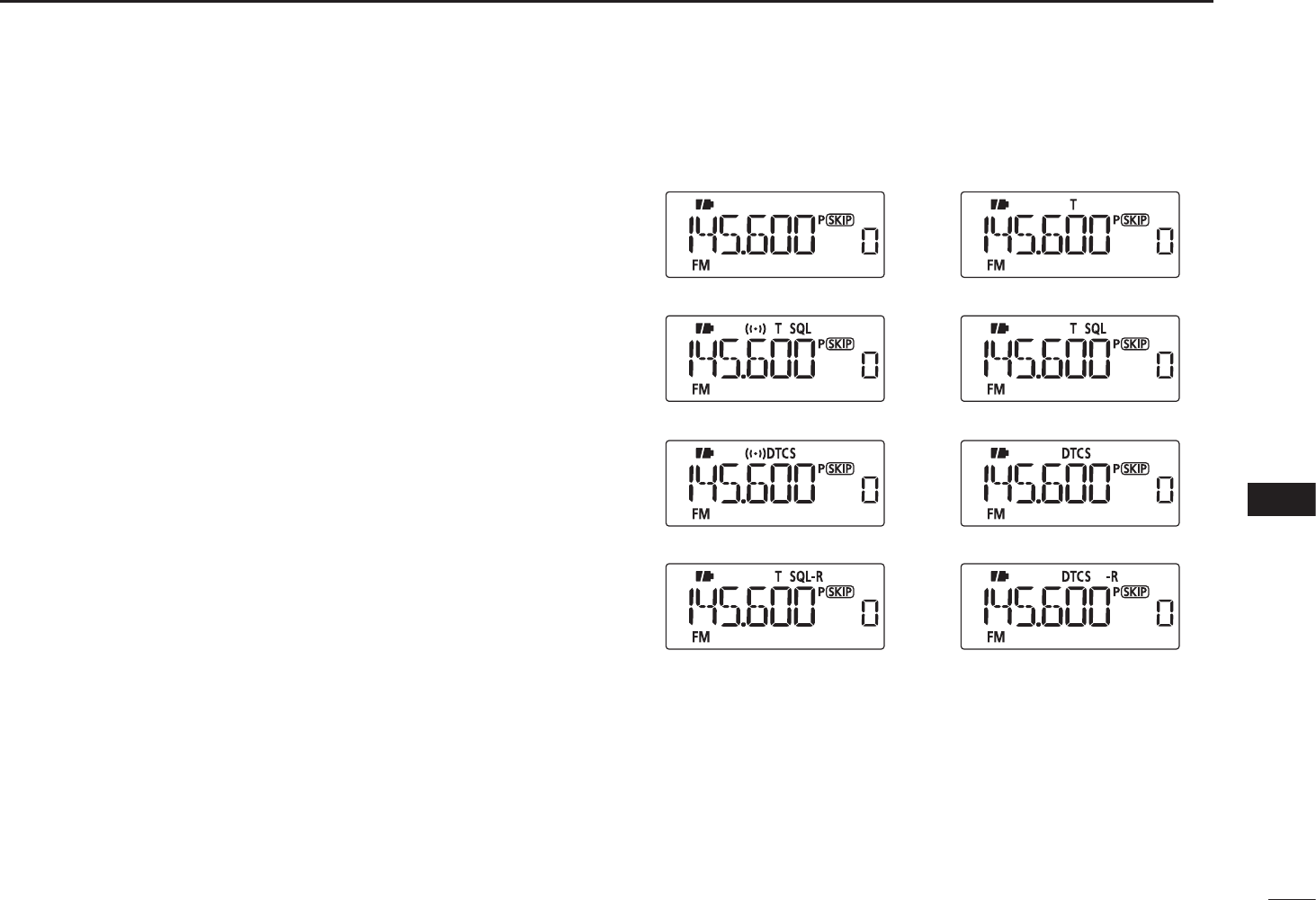
70
10
OTHER FUNCTIONS
1
2
3
4
5
6
7
8
9
10
11
12
13
14
15
16
17
18
19
N Tone/DTCS squelch
q Set a desired operating frequency, and then set a
CTCSS tone or DTCS code.
w Push and hold [TONE](0) for 1 sec. repeatedly to activate
the tone or DTCS squelch. (T SQL or DTCS)
• Subaudible tone encoder “T,” pocket beep (tone squelch)
“ST SQL,” tone squelch “T SQL,” DTCS beep “SDTCS,”
DTCS squelch “DTCS,” tone squelch reverse “T SQL-R,” DTCS
squelch reverse “DTCS-R” and no tone operation are select-
able in order.
e Operate the transceiver in the normal way.
r When the received signal includes a matching tone/code,
the squelch opens and the signal can be heard.
When the pocket beep function is activated, the trans-
ceiver also emits beep tones and blinks ““S.”
• When the received signal’s tone/code does not match, tone/
DTCS squelch does not open, however, the S-indicator shows
signal strength.
• To open the squelch manually, push and hold [MONI](BAND).
t Push [PTT] to answer or push and hold [MONI](BAND)
for 1 sec. to stop the beeps and blinking.
No tone operation Subaudible tone encoder
Tone squelchPocket beep
DTCS beep DTCS squelch
Tone squelch (reverse) DTCS squelch (reverse)
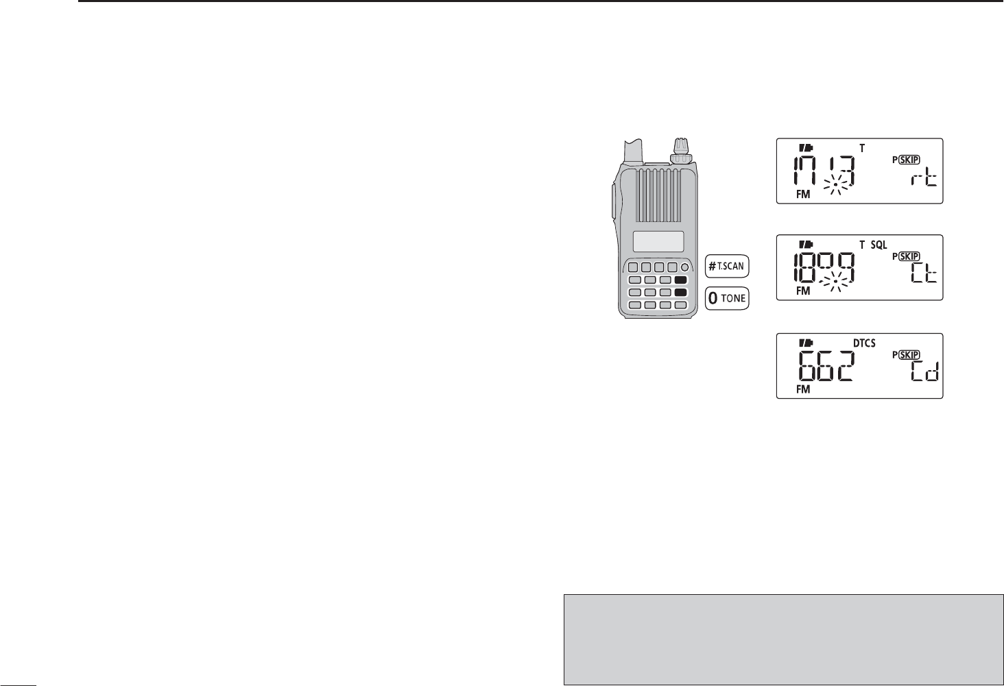
N Tone scan
The transceiver can detect the subaudible tone frequency
and DTCS code in a received signal. By monitoring a signal
that is being transmitted on a repeater input frequency, you
can determine the tone frequency required to access the re-
peater.
q Set the desired frequency or memory channel to be
checked for a tone frequency or DTCS code.
w Push and hold [TONE](0) for 1 sec. repeatedly to activate
the repeater tone, tone squelch or DTCS squelch. (T,
T SQL or DTCS)
e Push and hold [T.SCAN](#) for 1 sec. to start the tone
scan.
• To change the scanning direction, rotate [DIAL].
r When the tone frequency or DTCS code is decoded, the
set mode contents are programmed with the frequency or
code.
• The tone scan pauses for the set period in scan pause timer
(p. 47) when a tone frequency or DTCS code is detected.
• The decoded tone frequency is used for the repeater tone fre-
quency when any tone setting, such as repeater tone or tone
squelch is OFF.
• The decoded tone frequency is used for the tone squelch fre-
quency when the tone squelch is ON.
• The decoded DTCS code is used for the DTCS squelch code
when the DTCS squelch is ON.
Tone scan for repeater tone
Tone scan for tone squelch
tPush [V/M/C] to stop the scan.
• If the scan is cancelled before the transceiver detects the tone
or code, the set mode contents are not changed.
• The detected tone is used for temporary operation only.
The stored tone setting in memory or call channel won’t be
changed.
71
10 OTHER FUNCTIONS
NOTE: Tone frequency is over-written automatically when
it corresponds with the scanning tone frequency in tone
squelch mode. However, it is not over-written in memory or
call channel mode.
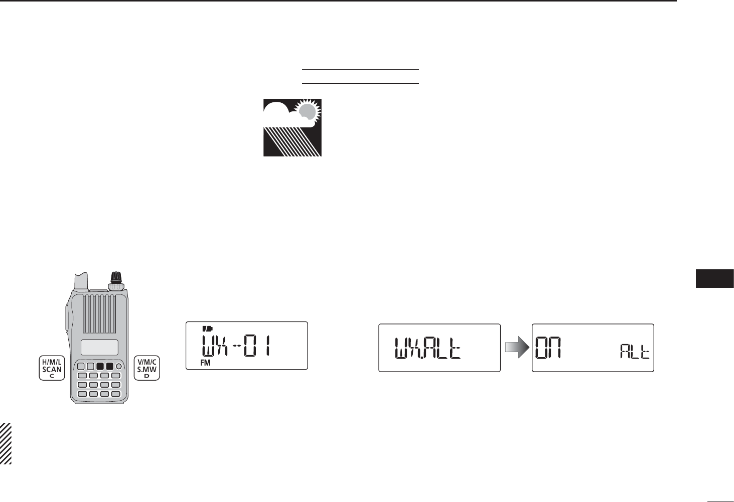
72
10
OTHER FUNCTIONS
1
2
3
4
5
6
7
8
9
10
11
12
13
14
15
16
17
18
19
There are 10 weather channels for monitoring
weather broadcasts from the NOAA (National
Oceanic and Atmospheric Administration).
D Weather channel selection
q Push [V/M/C] repeatedly to select weather channel
mode.
• “WX” and the weather channel number appear.
wRotate [DIAL] to select a desired weather channel.
e Push [V/M/C] to return to the previous frequency or mem-
ory channel.
[DIAL]
Weather channel indication
Push and hold [SCAN](H/M/L) for 1 sec. activates the
weather channel scan. Push [SCAN](H/M/L) again to stop
the scan.
D Weather alert function
NOAA broadcast stations transmit weather alert tones be-
fore important weather announcements. When the weather
alert function is turned ON, the selected weather channel is
monitored every 5 seconds for the announcement. When the
alert signal is detected, the “ALT” and the WX channel in-
dications are displayed alternately and a beep sounds until
the transceiver is operated. The previously selected (used)
weather channel is checked periodically during standby or
while scanning.
qSelect the desired weather channel.
w Push [SET] to enter the Set mode.
e Rotate [DIAL] to select the weather alert setting item, then
rotate [VOL] to select “On.”
rPush [V/M/C] to return to the weather channel display.
tSet the desired stand-by condition.
• Select VFO, memory or call channel.
• Scan or priority watch operation can also be selected.
NWeather channel operation U.S.A. version only
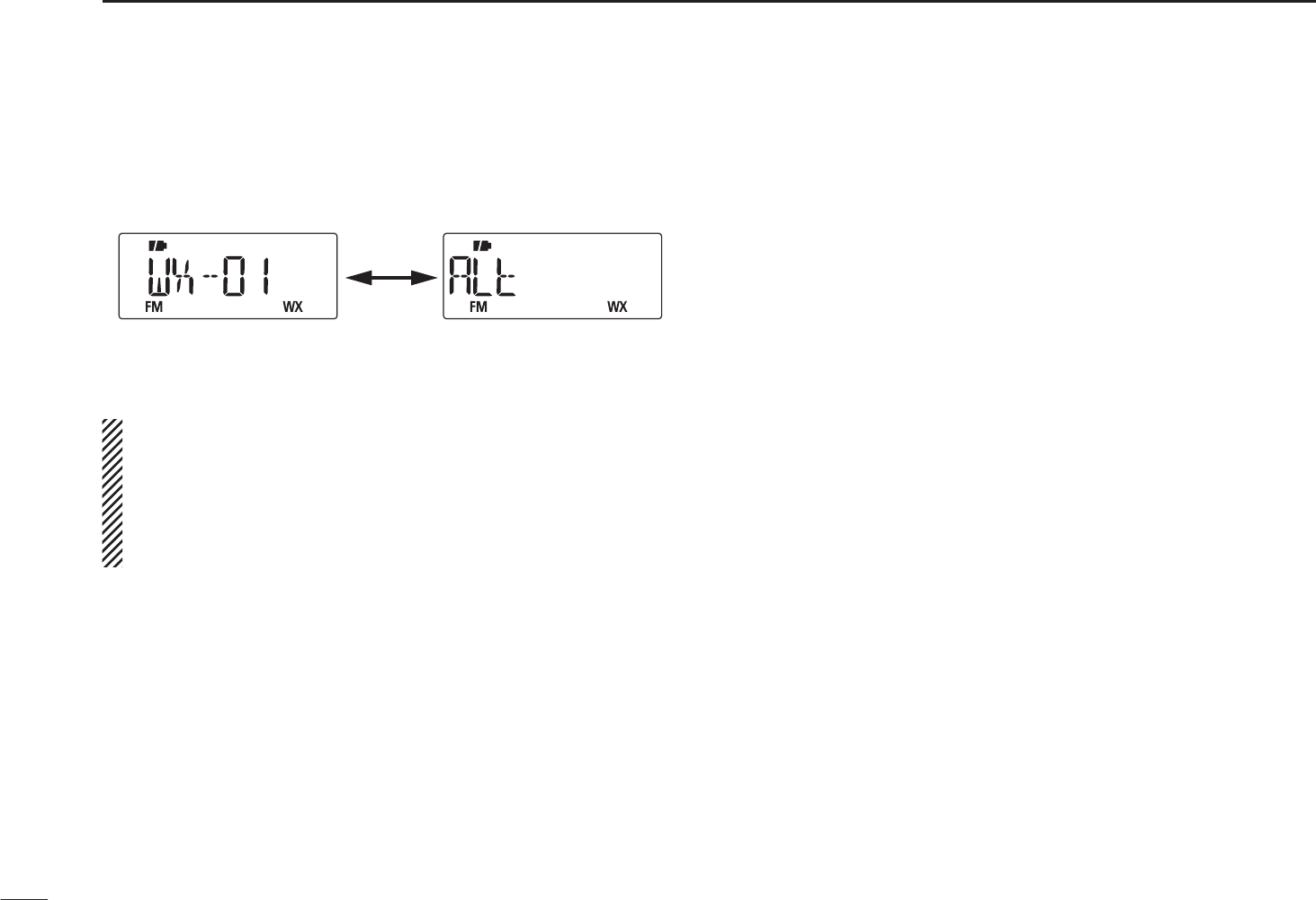
DWeather alert function (continued)
y When the alert is detected, a beep sounds and the follow-
ing indication is displayed.
Shows above indications alternately.
uTurn the weather alert function OFF in the Set mode.
NOTE: While receiving a signal on a frequency other than
the Weather alert frequency, the receiving signal will be
interrupted momentarily approximately every 5 seconds
when the Whether alert function is ON. These interrup-
tions cease when the Weather alert function is turned
OFF.
73
10 OTHER FUNCTIONS
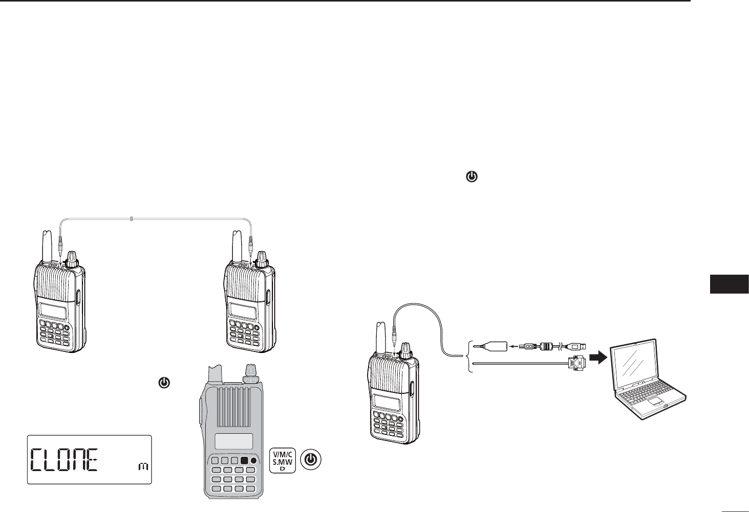
74
10
OTHER FUNCTIONS
1
2
3
4
5
6
7
8
9
10
11
12
13
14
15
16
17
18
19
N Cloning function
The IC-T70A/T70E has transceiver-to-transceiver data clon-
ing capability. This function is useful when you want to copy
all of the programmed contents from one IC-T70A/T70E to
another.
• An optional OPC-474 CLONING CABLE is required.
q Turn the transceiver’s power OFF, then connect an optional
OPC-474 between both [SP] jacks.
OPC-474
to the [SP] jack to the [SP] jack
w While continuing to push
[V/M/C], push and hold []for
1 sec. to enter the cloning mode.
• “CLOnE m” appears.
ePush [PTT] on the “master” transceiver.
• “CL OUt m” appears and the bar meter shows that cloning is
taking place.
• After the cloning is completed, the display returns to “CLOnE
m.”
rPush and hold [ ] for 1 sec. to turn power OFF.
The optional CS-T70 CLONING SOFTWARE is also available
to clone/edit contents with a PC (for Microsoft
®
Windows
®
2000/XP, Windows Vista
®
or Windows
®
7) using ICF format
files.
PC
OPC-478
(RS-232C type)
OPC-478UC
(USB type) to USB port
to RS-232C
port
to the
[SP] jack
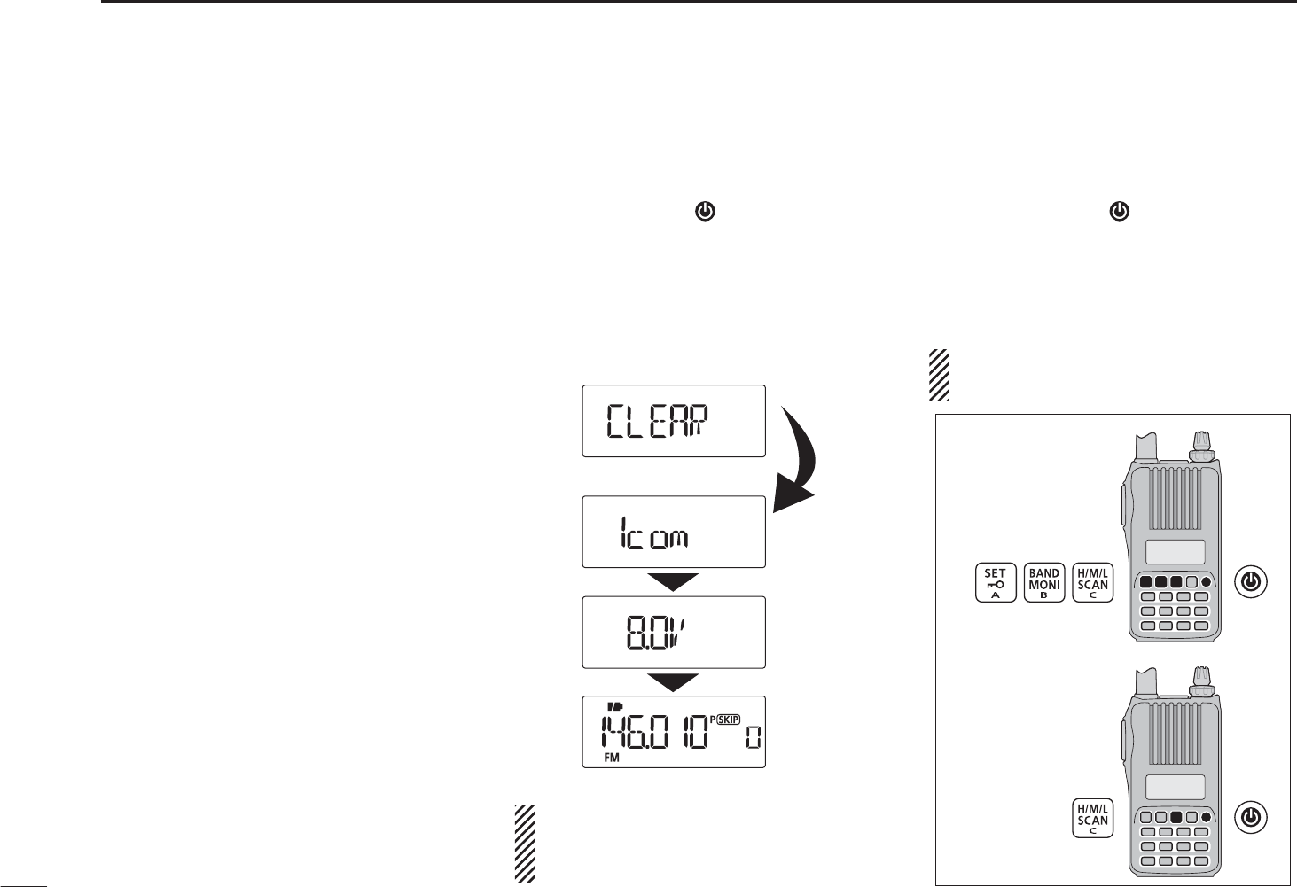
75
10 OTHER FUNCTIONS
N Resetting
The display may occasionally display
erroneous information (e.g. when first
applying power). This may be caused
externally by static electricity or by
other factors.
If this problem occurs, turn power OFF.
After waiting a few seconds, turn power
ON again. If the problem persists, per-
form either or both procedures below.
• All reset
Reset the CPU before operating the
transceiver for the first time, or if the
internal CPU malfunctions due to static
electricity, etc. All reset clears all pro-
gramming and returns all settings to
their factory defaults.
• Partial reset
Use Partial reset if you want to initial-
ize the operating conditions (VFO
frequency, VFO settings, set mode
contents) without clearing the memory
contents.
D All reset
q Push and hold [ ] for 1 sec. to turn
power OFF.
w While continuing to push [SET],
[BAND] and [H/M/L], then turn
power ON to reset the CPU.
• “CLEAR” appears when resetting the
CPU (See the illustration below).
CAUTION: Resetting the CPU re-
turns all programmed contents to
their default settings.
D Partial reset
q Push and hold [ ] for 1 sec. to turn
power OFF.
w While continuing to push [V/M/C],
then turn power ON to partially
reset the transceiver.
NOTE: No message appears on the
display after the partial reset is done.
All reset
Partial reset

76
11
TROUBLESHOOTING
1
2
3
4
5
6
7
8
9
10
11
12
13
14
15
16
17
18
19
If your transceiver seems to be malfunctioning, please check the following points before sending it to a service center.
PROBLEM POSSIBLE CAUSE SOLUTION REF.
Transceiver does not turn
ON.
• The battery is exhausted.
• The battery polarity is reversed.
• Loose connection of a battery pack (case).
• Charge the battery pack, or replace the batteries.
• Check the battery polarity.
• Clean battery terminals.
pp. 2, 11–14
p. 11
–
No sound comes from the
speaker.
• Volume level is too low.
• An external speaker or a cloning cable is con-
nected to the [SP] jack.
• Rotate [VOL] to adjust to a desired level.
• Check the external speaker connection or remove
the cloning cable.
p. 16
–
Transmitting is impossible. • A frequency outside of the 144/400 MHz ama-
teur bands is set.
• The PTT lock function is activated.
• The heat protection is activated, and “Hot” is
displayed.
• Set the frequency within 144/400 MHz amateur
bands.
• Set the PTT lock function OFF in the Initial set mode.
• Cool down the transceiver.
p. 20
p. 62
p. 23
Transmitting using the VOX
function is impossible.
• The VOX gain is set to OFF or too low.
• The microphone gain is too low.
•
Set the VOX gain to a suitable level.
•
Set the microphone gain to a suitable level.
p. 81
p. 58
Contacting with another
station is impossible.
• Different tone or code is used for the tone/
DTCS squelch.
• Check the tone/DTCS by performing a tone scan. p. 71
Frequency cannot be set. • The lock function is activated.
• The memory mode, Call channel mode, or
weather channel mode is selected.
• Push and hold [](SET) for 1 sec. to cancel the
lock function.
• Push [V/M/C] repeatedly to select the VFO mode.
p. 21
p. 18
A program scan does not
start.
• The memory mode, Call channel mode, or
weather channel mode is selected.
• The same frequency has been programmed in
the scan edge channels, “1A” and “1b.”
• Push [V/M/C] repeatedly to select the VFO mode.
• Programming different frequencies in the scan edge
channels.
p. 18
p. 43
A memory scan does not
start.
•
The VFO mode or Call channel mode is selected.
• Only one or no memory channel has been pro-
grammed.
•
Push [V/M/C] repeatedly to select the memory mode.
• Program 2 or more memory channels.
p. 18
p. 31
The displayed frequency is
erroneous.
• The CPU has malfunctioned.
• External factors have caused a fault.
• Reset the transceiver.
• Remove and re-attach the battery pack/case.
p. 75
p. 2

77
SPECIFICATIONS
12
D General
• Frequency coverage : (unit: MHz)
Version TX RX
EUR, KOR 144–146, 430–440 144–146, 430–440
UK, RSP 144–146, 430–440 136–174*1, 400–479*2
U.S.A. 144–148, 420–450*4136–174*3, 400–479*4
TPE 144–146, 430–432 144–146, 430–432
AUS 144–148, 420–450*2136–174*3, 400–479*2
CHN, EXP 136–174*3, 400–479*2136–174*3, 400–479*2
*1Guaranteed 144–146 MHz only, *2Guaranteed 430–440 MHz only,
*3Guaranteed 144–148 MHz only, *4Guaranteed 440–450 MHz only
• Mode :
FM, FM-N
• No. of memory channels : 302
(incl. 50 scan edges and 2 call channels)
• Usable temp. range : –20°C to +60°C; –4°F to +140°F
• Tuning steps : 5, 10, 12.5, 15, 20, 25, 30, 50, 100,
125 and 200 kHz
• Frequency stability :
±2.5 ppm
(–20°C to +60°C; –4°F to +140°F)
• Power supply : 10.0–16.0 V DC for external DC power,
or specified Icom battery pack
• Current drain (at 7.2 V DC) :
TX High(typical) VHF 1.7 A, UHF 2.1 A
Mid. (typical) VHF 1.2 A, UHF 1.5 A
Low (typical) VHF 0.6 A, UHF 0.8 A
Rx Max. output Less than 450 mA (Internal speaker)
Less than 300 mA (External speaker)
Power save Less than 40 mA (Duty 1:8)
standby Less than 90 mA
• Antenna connector : SMA (50 :)
• Dimensions : 58(W)u111(H)u30(D) mm;
(projections not included) 2
9⁄32(W)u43⁄8(H)u13⁄16(D) in
• Weight (approx.) : 380 g; 13.4 oz (with antenna and BP-264)
D Transmitter
• Modulation system : Variable reactance freq. modulation
• Output power (at 7.2 V DC) : High 5.0 W, Mid. 2.5 W, Low 0.5 W
(typical)
• Max. frequency deviation : ±5.0 kHz (FM wide: approx.)
±2.5 kHz (FM narrow: approx.)
• Spurious emissions : Less than –60 dBc at High/Mid.
Less than –13 dBm at Low
• Ext. mic. impedance : 2.2 k:
D Receiver
• Receive system : Double-conversion superheterodyne
• Intermediate frequencies : 1st 46.35 MHz, 2nd 450 kHz
• Sensitivity (except spurious points, 1 kHz/3.5 kHz Dev.; 12 dB SINAD) :
Guaranteed freq. range Less than 0.18 μV
Other freq. range Less than 0.32 μV
• Squelch Sensitivity (except spurious points, 1 kHz/3.5 kHz Dev.) :
Guaranteed range Less than 0.18 μV
Other frequency range Less than 0.32 μV
• Audio output power : (at 10% distortion/7.2 V DC)
Internal speaker More than 700 mW with a 16 : load
External speaker More than 400 mW with an 8 : load
• Selectivity :
(at CH spacing 20 kHz/in the amateur bands)
FM (Wide) More than 60 dB
FM (Narrow) More than 60 dB
• Ext. speaker connector : 3-conductor 3.5(d) mm; (1⁄8˝)/8 :
• Spurious and image rejection ratio (in guaranteed freq. range) :
More than 60 dB
All stated specifications are subject to change without notice or obligation.

78
13
OPTIONS
1
2
3
4
5
6
7
8
9
10
11
12
13
14
15
16
17
18
19
• BP-263 BATTERY CASE
Battery case for LR6 (AA) u 6 alkaline batteries.
• BP-264 NI-MH BATTERY PACK
7.2 V/1400 mAh (Typ.) Ni-MH battery pack. Battery life:
11.5 hrs. (approx.; VHF, FM, high power, Tx : Rx : Standby
= 5:5:90)
• BP-265 LI-ION BATTERY PACK
7.4 V/1900 mAh (Min.)/2000 mAh (Typ.) Lithium Ion battery
pack. Battery life: 16 hrs. (approx.; VHF, FM, high power, Tx
: Rx : Standby = 5:5:90)
• BC-167SA/SC/SV BATTERY CHARGER
For regular charging of the battery pack BP-264.
• BC-191 DESKTOP CHARGER+BC-123S AC ADAPTER
For rapid charging of the Ni-MH battery pack. An AC
adapter may be supplied with the charger, depending on
the version.
Charging time: approx. 2 hours for the BP-264.
• BC-193 DESKTOP CHARGER+BC-123S AC ADAPTER
For rapid charging of the Li-Ion battery pack. An AC
adapter may be supplied with the charger, depending on
the version.
Charging time: approx. 2.5 hours for the BP-265.
BC-191/BC-193 common specifications
Power supply voltage 12 to 16 V DC or the specified
Icom AC adapter (BC-123S)
Charging temp. range +10°C to +40°C;
+50°F to +104°F
Dimensions
(projections not included)
87.5(W)u53.7(H)u72.8(D) mm;
37⁄16(W)u21⁄8(H)u27⁄8(D) in
•CP-12L CIGARETTE LIGHTER CABLE WITH NOISE FILTER
•CP-19R CIGARETTE LIGHTER CABLE WITH DC-DC CONVERTER
Allows you to operate the transceiver through a 12 V ciga-
rette lighter socket. You can also charge the attached bat-
tery pack (during stand-by only).
CP-19R: A built-in DC-DC converter provides an 11 V DC
output.
•OPC-254L DC POWER CABLE
For operation and charging via an external power supply.
• CP-23L CIGARETTE LIGHTER CABLE
Allows charging of the battery packs through a 12 V ciga-
rette lighter socket. (For BC-191/BC-193)
• OPC-515L DC POWER CABLE
Allows charging of the battery packs using a 12 V DC
power source instead of the AC adapter. (For BC-191/
BC-193)

79
13 OPTIONS
• AD-92SMA ANTENNA CONNECTOR ADAPTER
Allows you to connect an external antenna with a BNC
connector.
• HM-131 SPEAKER-MICROPHONE
Combination speaker-microphone that provides convenient
operation while hanging the transceiver on your belt.
• HM-153/HM-166 EARPHONE-MICROPHONE
Ideal for hands-free operation: clip the HM-153/HM-166
(with integrated PTT switch) to your lapel or breast pocket.
•HS-94/HS-95/HS-97 HEADSET
+OPC-2006 PLUG ADAPTER CABLE
HS-94 : Ear hook type
HS-95 : Neck & arm type
HS-97 : Throat microphone
OPC-2006 : Allows you to connect the HS-94/HS-95/HS-97
to the transceiver. After connecting, the VOX
function can be used.
•SP-13 EARPHONE
Provides clear audio in noisy environments.
•OPC-474 CLONING CABLE
For transceiver-to-transceiver cloning.
•OPC-478/478UC CLONING CABLE
Used for data cloning between transceiver and PC with
CS-T70 (cloning software).
• CS-T70 CLONING SOFTWARE
Provides quick and easy programming of such settings as
memory channels and Set modes contents via your PC’s
RS-232C terminal (using OPC-478), or USB port (OPC-
478UC). Either OPC-478 or OPC-478UC is required.
•LC-174 CARRYING CASE
Helps protect the transceiver from scratches, etc.
Approved Icom optional equipment is designed for optimal
performance when used with an Icom transceiver.
Icom is not responsible for the destruction or damage to an
Icom transceiver in the event the Icom transceiver is used
with equipment that is not manufactured or approved by
Icom.
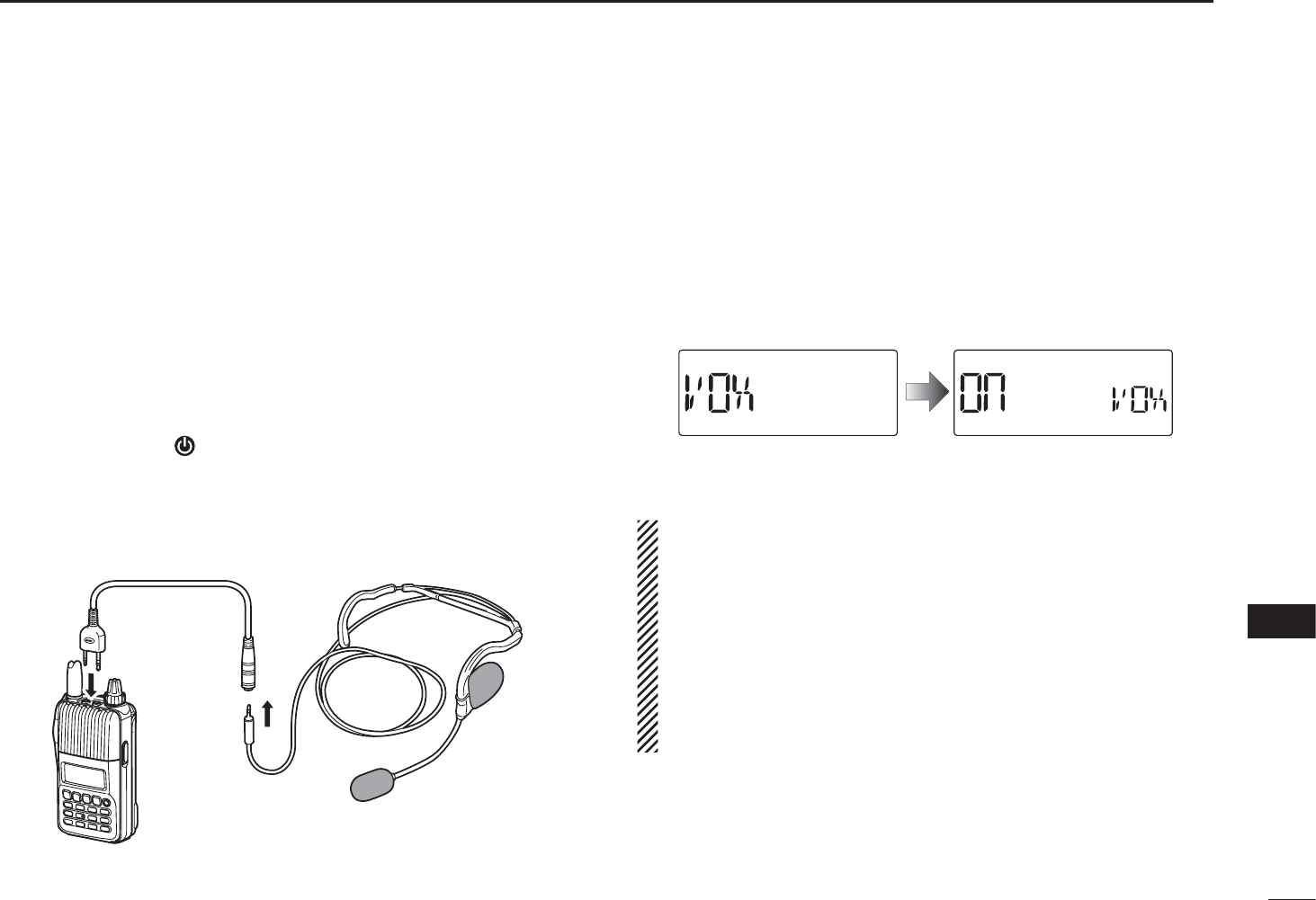
80
13
OPTIONS
1
2
3
4
5
6
7
8
9
10
11
12
13
14
15
16
17
18
19
The transceiver has a VOX function, which allows hands-free
operation.
An optional HS-94, HS-95 or HS-97 headset and the
OPC-2006 plug adapter cable are also required for operation.
• The VOX (voice operated transmission) function starts transmis-
sion when you speak into the microphone, without needing to
push [PTT]; then, automatically returns to reception when you stop
speaking.
DOptional unit connection
q Push and hold [ ] for 1 sec. to turn the power OFF.
w Remove the jack cover.
e Connect the optional HS-94, HS-95 or HS-97 and OPC-
2006, as illustrated below.
OPC-2006
HS-95
Transceiver
DTurning the VOX function ON or OFF
q Connect an optional headset and plug adapter cable to the
transceiver, and then turn the power ON.
w Push [SET] to enter the Set mode.
e Rotate [DIAL] to select the VOX setting item, then rotate
[VOL] to select “On.”
rPush [V/M/C] to return to the frequency display.
•
“VOX” appears when the VOX function is ON.
NOTE:
• When using the VOX function, adjust the microphone gain
and the VOX-related settings (p. 81) to suit your operating
environment (including your headset performance).
• Set the microphone gain before setting the VOX gain in
the Set mode (p. 58). We recommend setting the micro-
phone gain to 3.
• When the PTT lock is set to “On” in the Set mode, you
cannot transmit using the VOX function. (p. 62)
N VOX function
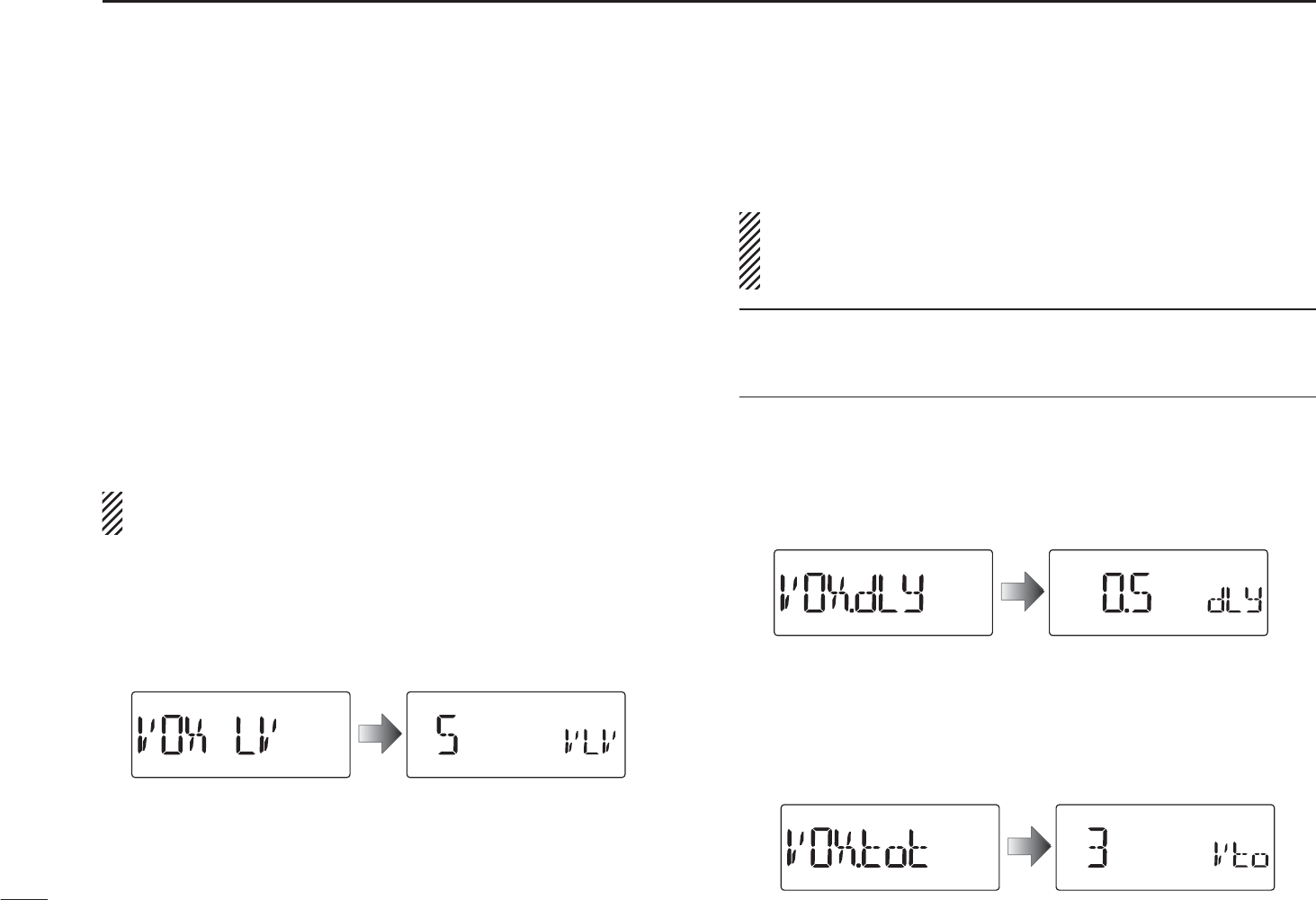
81
13 OPTIONS
DVOX-related settings
The VOX gain, the VOX delay, and the VOX time-out timer
can be set in the Set mode.
q Connect an optional headset and plug adapter cable to the
transceiver, and then turn the power ON.
w Push [SET] to enter the Set mode.
e Rotate [DIAL] to select the VOX gain (VOX LV), the VOX
delay (VOX.dLy), or the VOX time-out timer (VOX.tot) item.
r Rotate [VOL] to select a desired option.
tPush [V/M/C] to exit the Set mode.
The VOX function does not activate transmission while in
the Set mode.
•VOX gain
The VOX gain level can be adjusted between 1 (minimum)
and 10 (maximum), or turned OFF. Higher values make the
VOX function more sensitive to your voice. (default: 5)
±While speaking into the headset microphone, adjust the
VOX gain until “VOX” continuously appears on the LCD.
If “VOX” is intermittent, be sure the VOX delay is set long
enough to allow normal pauses in speech, but keep the
VOX ON until you finish speaking.
CONVENIENT!
While transmitting using the VOX function, you can adjust the
VOX gain simply by rotating [DIAL].
•VOX delay
Sets the VOX delay to between 0.5 and 3.0 seconds (in 0.5
sec. steps). The VOX delay is the amount of time the transmit-
ter stays ON after you stop speaking. (default: 0.5)
•VOX time-out timer
Sets the VOX time-out timer to between 1, 2, 3, 4, 5, 10 and
15 minutes to prevent accidental prolonged transmission for
the VOX function.
To turn the function OFF, select “OFF.” (default: 3)
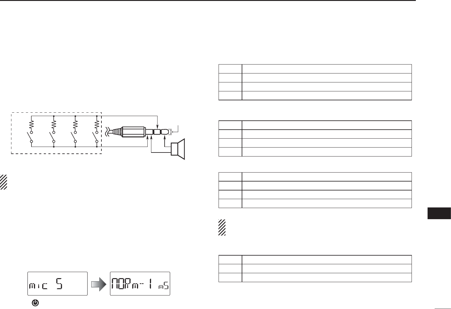
82
13
OPTIONS
1
2
3
4
5
6
7
8
9
10
11
12
13
14
15
16
17
18
19
N Remote control function
The remote control unit allows you to remotely select operat-
ing frequencies, memory channels, etc.
•User remote control unit
The below circuit is for reference only.
2.7k:6.8k:15k:33k:
+
–
S1 S2 S3 S4
to the [SP] jack
GND
SP
REMOTE
Rated input 700 mW (8 :)
EXTERNAL SPEAKER
3.5(d) mm
>
Ĵ
Be sure to turn power OFF when plugging/unplugging the
remote control unit to/from the [SP/MIC] jack.
D Simple remote control mode
q While continuing to push [SET], turn the power ON to
enter the Initial set mode.
w Rotate [DIAL] to select the microphone simple mode
(mic S) item.
e Rotate [DIAL] to select “SImPLE,” “nORm-1” or “nORm-2”
option.
r Push [ ] to return to the frequency display.
• SIMPLE
S1 Selects the Call channel.
S2 Turns the monitor function ON or OFF.
S3 Selects memory channel 0.
S4 Selects memory channel 1.
• NORM-1
S1 Toggles the VFO mode and the memory mode.
S2 Selects the Call channel.
S3 Frequency or memory channel “UP.”
S4 Frequency or memory channel “DOWN.”
• NORM-2
S1 Toggles the VFO mode and the memory mode.
S2 Turns the monitor function ON or OFF.
S3 Frequency or memory channel “UP.”
S4 Frequency or memory channel “DOWN.”
The VFO mode cannot be selected via the remote control
unit when SIMPLE mode is selected.
• COMMON (SIMPLE/NORM-1/NORM-2)
S2 Transmits T-CALL (1750 Hz tone) while pushing [PTT].
S3 Volume “UP” while operating the monitor function.
S4 Volume “DOWN” while operating the monitor function.
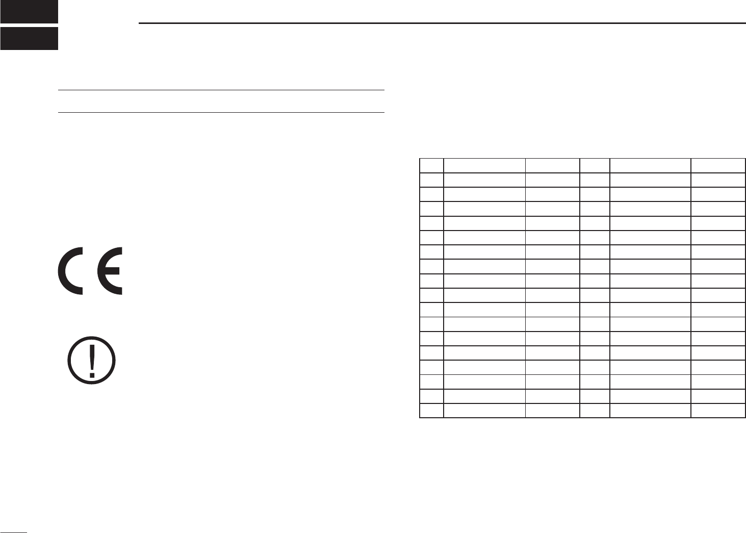
83
CE
14
IMPORTANT
• When transmitting with a portable radio, hold the radio in
a vertical position with its microphone 2.5 to 5 centimetres
from your head and body.
• If you wear a portable two-way radio on your body, ensure
that the antenna is at least 2.5 centimetres from your body
when transmitting.
CE Versions of the IC-T70E which display
the ‘CE’ symbol on the serial number label,
comply with the essential requirements of the
European Radio and Telecommunication Ter-
minal Directive 1999/5/EC.
This warning symbol indicates that this equip-
ment operates in non-harmonised frequency
bands and/or may be subject to licensing con-
ditions in the country of use. Be sure to check
that you have the correct version of this radio
or the correct programming of this radio, to
comply with national licensing requirements.
• List of Country codes (ISO 3166-1)
Country Codes Country Codes
1 Austria AT 18 Liechtenstein LI
2 Belgium BE 19 Lithuania LT
3 Bulgaria BG 20 Luxembourg LU
4 Croatia HR 21 Malta MT
5 Czech Republic CZ 22 Netherlands NL
6 Cyprus CY 23 Norway NO
7 Denmark DK 24 Poland PL
8 Estonia EE 25 Portugal PT
9 Finland FI 26 Romania RO
10 France FR 27 Slovakia SK
11 Germany DE 28 Slovenia SI
12 Greece GR 29 Spain EP
13 Hungary HU 30 Sweden SE
14 Iceland IS 31 Switzerland CH
15 Ireland IE 32 Turkey TR
16 Italy IT 33 United Kingdom GB
17 Latvia LV

84
14
CE
1
2
3
4
5
6
7
8
9
10
11
12
13
14
15
16
17
18
19

85
INDEX
– 1 –
1750 Hz tone ··················································································28
– A –
All reset···························································································75
Antenna ····························································································2
Auto low power (AUTOLP)······························································64
Auto power OFF (AP OFF)·····························································59
Auto repeater (AUTORP)································································60
Auto repeater function ····································································27
– B –
Band scan (VFO mode)··································································42
Battery caution ···············································································10
Battery icons···················································································12
Battery information ·········································································11
Battery life·······················································································11
Battery pack······················································································2
Beep output level (BEEPLV) ···························································60
Belt clip·····························································································1
Busy lockout (LK OUT)···································································62
– C –
Call channel mode··········································································18
Call channel watch ·········································································49
Caution (for the optional BP-265 Li-Ion battery pack) ······················9
Caution (for the supplied BP-264 Ni-MH battery pack) ····················8
CE·····························································································83, 84
Channel number display·································································36
Charging caution ············································································10
Charging note···········································································12–15
Checking the repeater input signal·················································25
Cloning function··············································································74
Copying call channel contents························································37
Copying memory contents······························································37
– D –
DC operating note ··········································································15
Dial speed acceleration (DIAL S) ···················································63
Display backlighting (LIGHT)··························································60
Display type ····················································································36
Display type (DISP M) ····································································64
DOC································································································84
DTCS code (CODE) ·······································································53
DTCS polarity (DTCS P) ································································53
DTCS squelch ················································································70
DTMF memory (DTMF) ··································································58
DTMF speed (DTMF-S)··································································61
DTMF TX key (DTMF-T)·································································58
Duplex operation ············································································26
– E –
Entering Initial set mode and operation··········································51
Entering Set mode and operation···················································51
Erasing bank contents····································································39
Explicit definitions·············································································· i
External DC power operation ·························································15

86
INDEX
1
2
3
4
5
6
7
8
9
10
11
12
13
14
15
16
17
18
19
– F –
FCC information ·············································································· iii
Features ···························································································· i
Foreword···························································································· i
Frequency display···········································································36
Frequency offset (OFFSET) ···························································54
Frequency range and offset direction ·············································27
Front panel························································································3
Full scan ·························································································42
Function display················································································6
– G –
General description ········································································29
– H –
Hand strap························································································1
Head set selection (HS SEL)··························································64
– I –
Important ··························································································· i
Index·························································································85–88
Initial set mode item list ··································································52
Initial set mode items······································································59
– K –
Key lock function·············································································21
Keypad······························································································4
– L –
LCD contrast (CONT)·····································································62
– M –
Memory bank link function (B LINK)···············································56
Memory bank scan ·········································································45
Memory bank selection ··································································33
Memory bank setting ······································································32
Memory channel contents ······························································29
Memory channel programming·······················································31
Memory channel watch···································································49
Memory clearing·············································································38
Memory mode ················································································18
Memory name (NAME)···································································63
Memory scan ·················································································44
Memory scan watch········································································49
Microphone gain (MIC G) ·······························································58
Microphone simple mode (MIC S)··················································59
Monitor function··············································································17
Monitor key action (MONI)······························································63
– O –
Off band indication··········································································25
Operating mode (MODE)································································54
Operating mode selection·······························································21
Optional battery case ·····································································11
Optional unit connection·································································80
Options ·····················································································78–82

87
INDEX
– P –
Partial reset ····················································································75
Pocket beep····················································································68
Power OFF ·····················································································16
Power ON ·······················································································16
Power save (P SAVE) ·····································································61
Precautions···················································································ii, iii
Priority watch (PRIO)······································································55
Priority watch operation··································································49
Priority watch types ········································································48
Private channel display···································································36
Program scan link function (P LINK) ··············································56
Program skip scan (P SKIP)···························································55
Programmed scan ·········································································42
Programming a DTMF code sequence···········································65
Programming bank name ·······························································34
Programming memory name··························································34
Programming scan name ·······························································34
PTT lock (PTT LK)··········································································62
– R –
Rapid charging with the BC-191·····················································13
Rapid charging with the BC-193·····················································14
Receiving························································································22
Regular charging ············································································12
Remote control function··································································82
Repeater operation·········································································24
Repeater tone frequency (R TONE) ···············································53
Resetting ························································································75
Reverse duplex function (DUP.REV)···············································54
Reverse tone/DTCS squelch ··························································68
Reverse duplex function ·································································26
– S –
Scan edges programming ······························································43
Scan name (S NAME) ····································································63
Scan pause timer············································································47
Scan pause timer (PAUSE)·····························································55
Scan resume condition···································································47
Scan resume timer ·········································································47
Scan resume timer (RESUME)·······················································55
Scan types······················································································40
Selecting a call channel··································································29
Selecting a memory channel ··························································30
Selecting bank name indication······················································35
Selecting memory name indication ················································35
Set mode item list···········································································52
Set mode items···············································································53
Setting a frequency using the dial ··················································19
Setting a frequency using the keypad·············································20
Setting a tuning step·······································································19
Setting audio volume ······································································16
Setting DTCS code for DTCS squelch ···········································69
Setting DTCS polarity·····································································69
Setting DTMF transfer speed··························································67
Setting duplex direction ··································································26
Setting frequency offset··································································26
Setting squelch level·······································································17

88
INDEX
1
2
3
4
5
6
7
8
9
10
11
12
13
14
15
16
17
18
19
Setting subaudible tone for tone squelch········································68
Setting the mode ············································································18
Side panel·························································································3
Skip channel setting ·······································································46
Skip frequency setting ····································································46
Specifications ·················································································77
Squelch delay (SQL DL)·································································62
Supplied accessories······································································· iv
– T –
Table of contents ··········································································v, vi
Time-out timer (TOT) ······································································62
Tone and DTCS squelches·····························································68
Tone frequency and DTCS code ····················································68
Tone scan ·······················································································71
Tone squelch ··················································································70
Top panel ··························································································3
Transferring bank contents ·····························································39
Transmit power selection ································································22
Transmit warning ············································································23
Transmitting ····················································································23
Transmitting a DTMF code sequence·············································66
Troubleshooting ··············································································76
TSQL frequency (C TONE)·····························································53
Tuning step (TS) ·············································································54
Tuning step selection ······································································19
Turning the VOX function ON or OFF ·············································80
– U –
Usable characters···········································································34
– V –
VFO mode ······················································································18
VFO scan watch ·············································································50
Voltage indication (VOLT) ·······························································61
VOX delay (VOX.DLY)·····································································59
VOX function···················································································80
VOX function (VOX) ········································································58
VOX gain (VOX LV)·········································································58
VOX time-out timer (VOXTOT)························································59
VOX-related settings·······································································81
– W –
Weather alert (WX.ALT)··································································54
Weather alert function ····································································72
Weather channel mode ··································································18
Weather channel operation·····························································72
Weather channel scan····································································72
Weather channel selection ·····························································72

1-1-32 Kamiminami, Hirano-ku, Osaka 547-0003, Japan
A-6808H-1EX
Printed in Japan
©2009 Icom Inc.
Printed on recycled paper with soy ink.