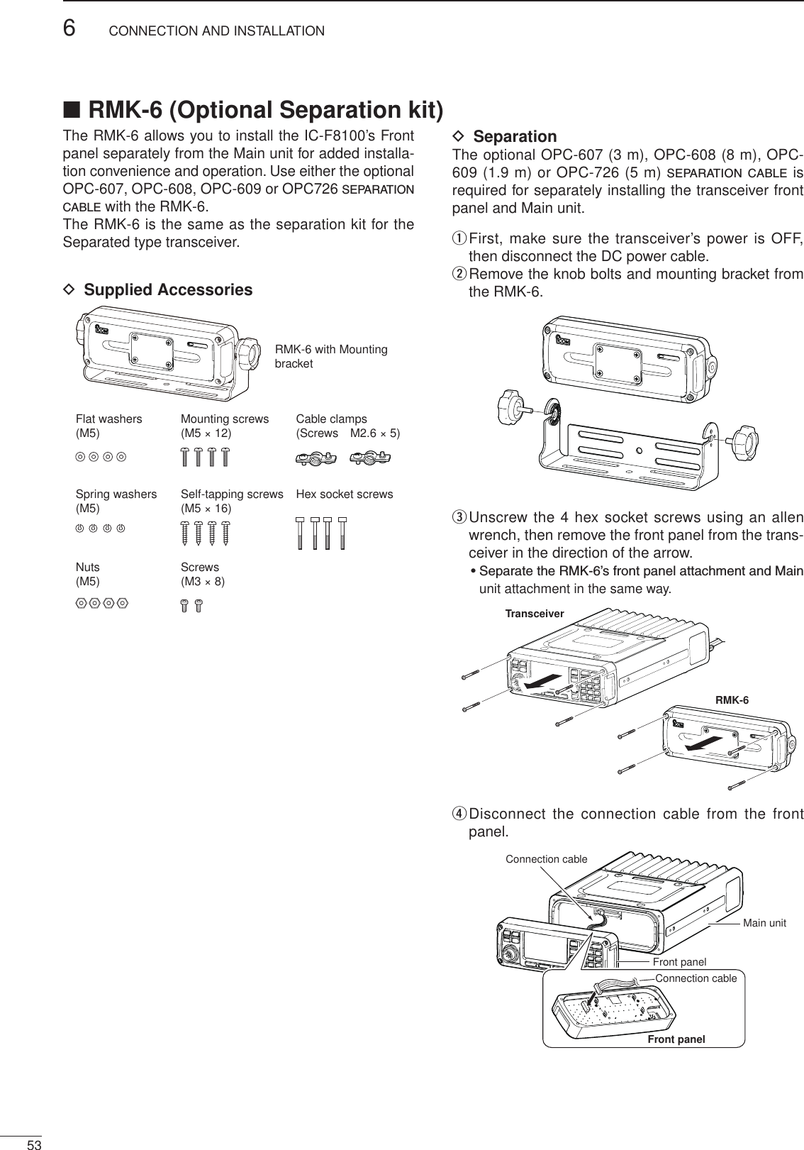
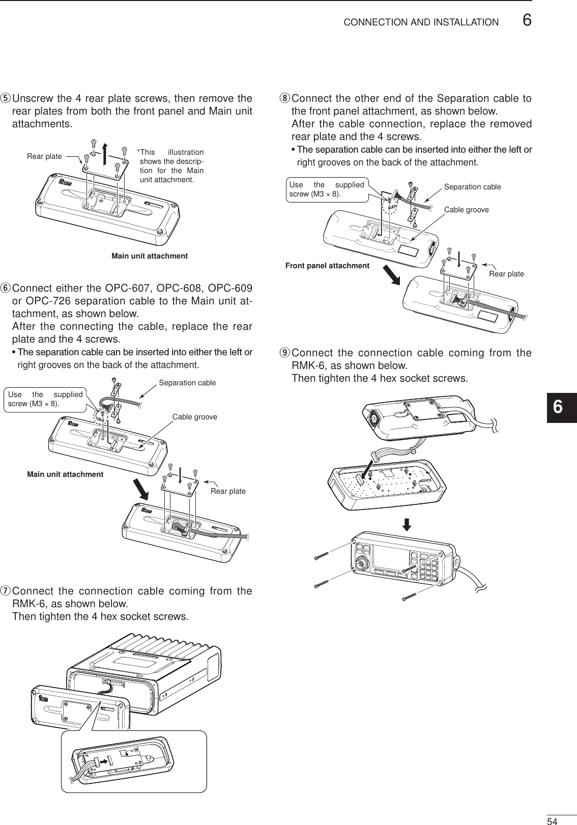
ICOM orporated 329600 HF TRANSCEIVER User Manual
ICOM Incorporated HF TRANSCEIVER
UserManual.wiki
>
ICOM orporated
>
329600 User Manual
User Manual
Navigation menu
Upload a User Manual
Namespaces
Wiki Guide
HTML
PDF
Info
Views
User Manual
Discussion / Help
Navigation
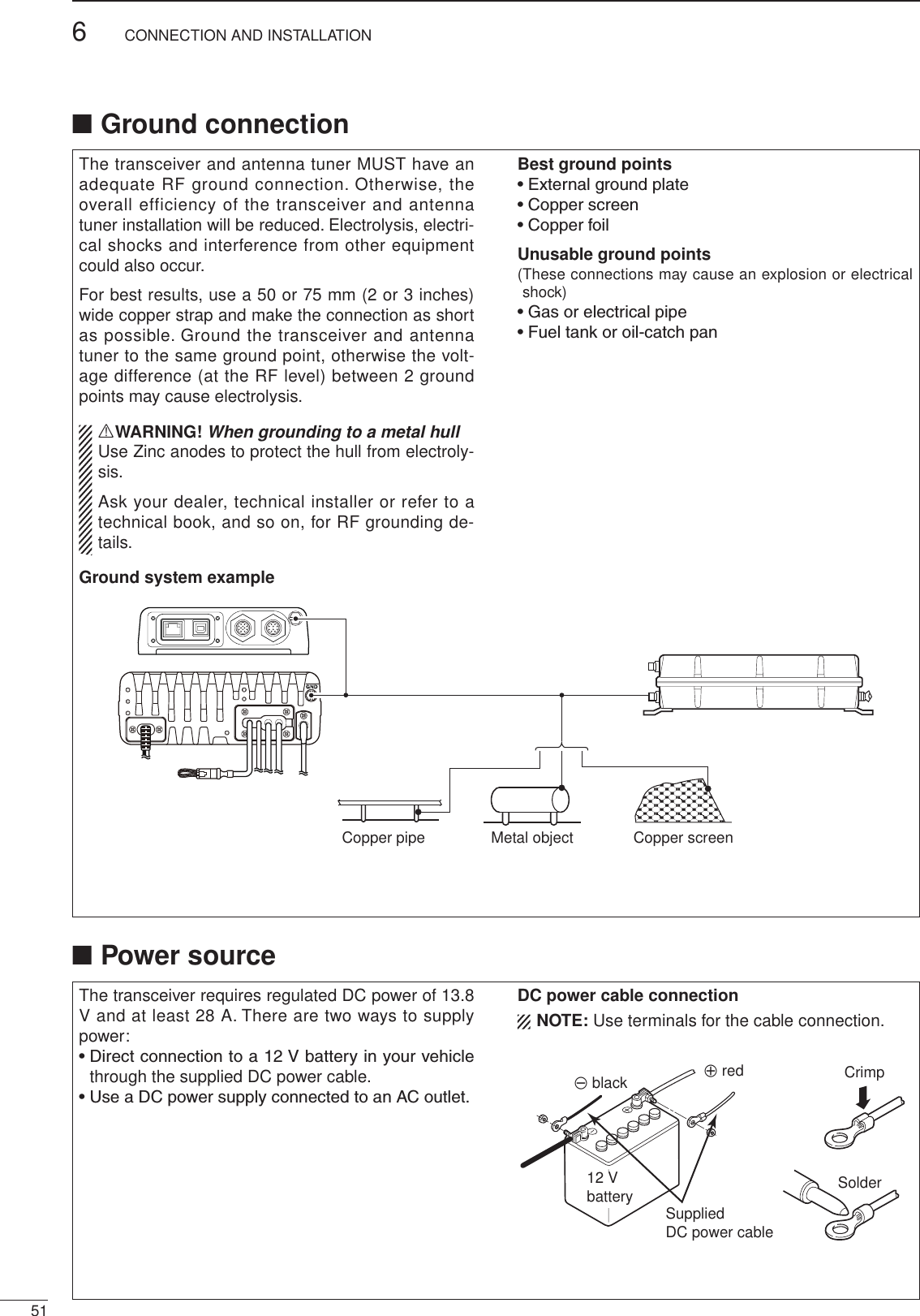
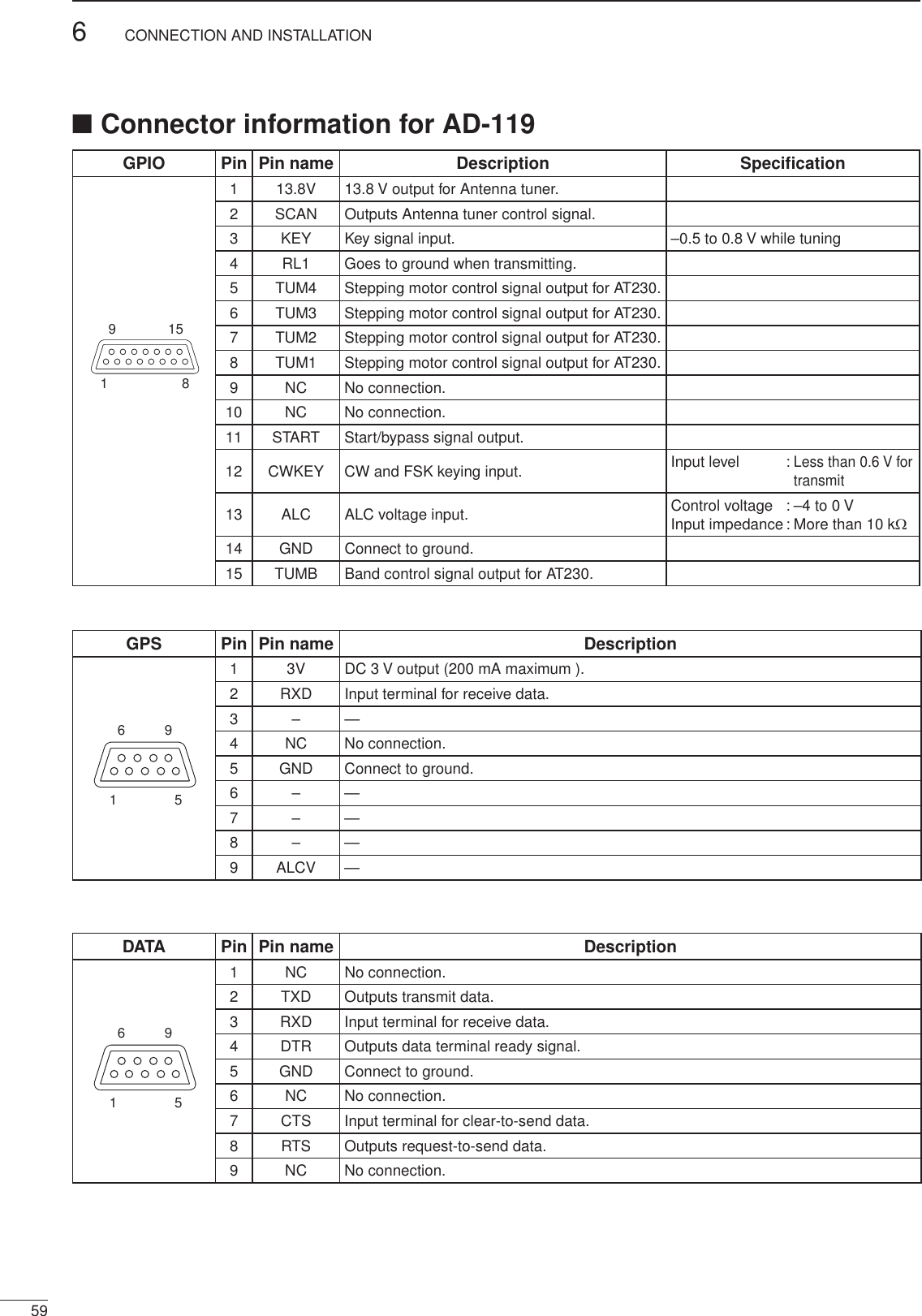
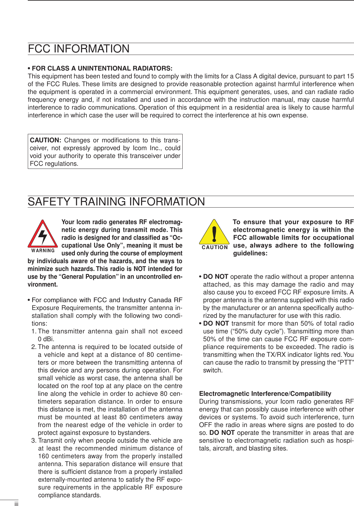
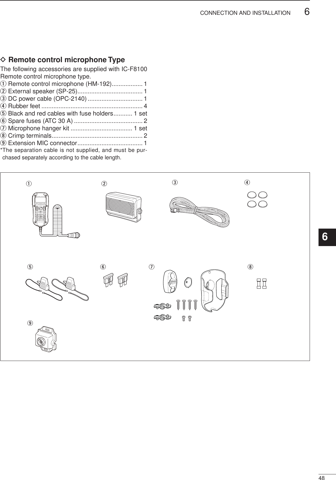
![2001 NEWiiPRECAUTIONSR DANGER HIGH RF VOLTAGE! NEVER attach an antenna or internal antenna connector during trans-mission. This may result in an electrical shock or burn.R WARNING! NEVER operate the transceiver with a headset or other audio accessories at high volume levels. Hearing experts advise against continuous high volume operation. If you experience a ringing in your ears, reduce the volume or discontinue use.R WARNING! NEVER operate or touch the trans-ceiver with wet hands. This may result in an electric shock or damage to the transceiver.R WARNING! NEVER apply AC power to the [DC13.8V] socket on the transceiver rear panel. This could cause a fire or damage the transceiver.R WARNING! NEVER apply more than 16 V DC to the [DC13.8V] socket on the transceiver rear panel, or use reverse polarity. This could cause a fire or damage the transceiver.R WARNING! NEVER let metal, wire or other objects protrude into the transceiver or into connectors on the rear panel. This may result in an electric shock.R WARNING! ALWAYS use the supplied Black and red cables with fuse holders. After connecting the fuse holders, NEVER cut the DC power cable between the DC plug and fuse holder. If an incorrect connection is made after cutting, the transceiver might be damaged.R WARNING! Immediately turn OFF the transceiver power and remove the power cable if it emits an abnor-mal odor, sound or smoke. Contact your Icom dealer or distributor for advice.CAUTION: NEVER change the internal settings of the transceiver. This may reduce transceiver performance and/or damage to the transceiver.In particular, incorrect settings for transmitter circuits, such as output power, idling current, and so on, might damage the expensive final devices.The transceiver warranty does not cover any problems caused by unauthorized internal adjustment.CAUTION: NEVER install the transceiver in a place without adequate ventilation. Heat dissipation may be reduced, and the transceiver may be damaged.DO NOT use or place the transceiver in direct sunlight or in areas with temperatures below –30°C (+32°F) or above +60°C (+122°F).The basic operations, transmission and reception of the transceiver are guaranteed within the specified operat-ing temperature range. However, the LCD display may not be operate correctly, or show an indication in the case of long hours of operation, or after being placed in extremely cold areas.DO NOT use harsh solvents such as benzine or alco-hol when cleaning, as they will damage the transceiver surfaces.DO NOT push the PTT switch when you don’t actually desire to transmit.DO NOT place the transceiver against walls or putting anything on top of the transceiver. This may overheat the transceiver.Always place unit in a secure place to avoid inadvertent use by children.BE CAREFUL! If you use a linear amplifier, set the transceiver’s RF output power to less than the linear amplifier’s maximum input level, otherwise, the linear amplifier will be damaged.BE CAREFUL! The transceiver will become hot when operating the transceiver continuously for long periods of time.USE only the specified microphone. Other manufactur-ers’ microphones have different pin assignments, and connection to the IC-F8100 may damage the transceiver or microphone.During mobile operation, NEVER place the transceiver where air bag deployment may be obstructed.During mobile operation, DO NOT place the transceiver where hot or cold air blows directly onto it.During mobile operation, DO NOT operate the trans-ceiver without running the vehicle’s engine. When the transceiver’s power is ON and your vehicle’s engine is OFF, the vehicle’s battery will soon become exhausted.Make sure the transceiver power is OFF before starting the vehicle engine. This will avoid possible damage to the transceiver by ignition voltage spikes.During maritime mobile operation, keep the trans-ceiver and microphone as far away as possible from the magnetic navigation compass to prevent erroneous indi-cations.Turn OFF the transceiver’s power and/or disconnect the DC power cable when you will not use the transceiver for long period of time.KEEP the transceiver away from the heavy rain, and Never immerse it in the water. The transceiver meets IP54* requirements for dust-protection and splash resis-tance.However, once the transceiver has been dropped, dust-protection and splash resistance cannot be guaranteed due to the fact that the transceiver may be cracked, or the waterproof seal damaged, and so on.* Only when the supplied microphone is attached.12345678](https://usermanual.wiki/ICOM-orporated/329600/User-Guide-1729805-Page-3.png)
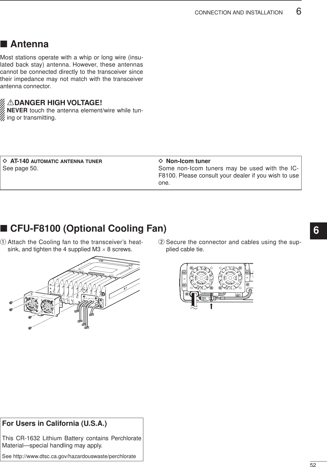
![2001 NEW2001 NEW11PANEL DESCRIPTION2001 NEWq VOLUME KEYS [ +]/[ –](p. 9)Adjusts the audio output level.w EMERGENCY KEY [ ] NOTE: While in the VFO mode, the Emergency key cannot be used.➥ Push to enter the Emergency channel list. • Push again to return to the normal operating screen.➥ Hold down for 1 second to transmit the Selcall and RFDS (Royal Flying Doctor Service) calls to the specified Selcall addresses in sequential order. NOTE: RFDS calls are available in only the AUS versions.e POWER KEY [ ] ➥ When the transceiver’s power is OFF: Push to turn ON the transceiver power. • First, turn ON the DC power source. ➥ When the transceiver’s power is ON: Hold down for 2 seconds to turn OFF the power.r CALL KEY [ ]Push to enter the Call menu. • Push again to go to the next screen in the Call menu.t UP/DOWN KEYS [r]/[s]Selects the operating channel, the items in the Menu mode, and so on.y ENTER KEY [4] Push to enter or exit the selected Menu in the Menu screen.u CLEAR KEY [8]➥ Push to exit the Menu screen.➥ Push to return to the previous screen in the Call menu. i HOME/MENU KEY [HOME] [MENU](HOME)➥ Push to return to the home display. ➥ Hold down for 1 second to enter the Menu screen.o FUNCTION KEYS [§]/[§§]/[§§§] Push to select the function that is displayed above each key on the LCD display. • The functions vary, depending on the selected menu and the operating mode.q ww !1eerio!0tyuKeypad (p. 2)qouytri• HM-192• Front panel■ Controller (Front panel or HM-192)• Common](https://usermanual.wiki/ICOM-orporated/329600/User-Guide-1729805-Page-6.png)
![2001 NEW21PANEL DESCRIPTION2001 NEW1234567891011121314151617Quick Reference!0 MICROPHONE CONNECTOR [MIC]Connects to only the microphone supplied with the transceiver. NOTE: NEVER connect the HM-192 or any other microphone here. This could damage the trans-ceiver and/or the microphone.yutrqweiFront view q MIC (microphone input)w MIC SW1e AFr MIC SW2t PTTy GNDu GND (microphone ground)i +8 V DC output (Max 10 mA)!1 LOCK KEY [ ]Hold down for 1 second to set the Key lock function to ALL, NUMERIC KEY or OFF.D Keypad➥ Inputs numbers for the Clock Setting.➥ Inputs numbers, characters or letters for the Sel-call direct input.10-key• Front panel • HM-192• Selectable charactersKEY INPUT INPUTKEY(space)Upper/Lower case letters/Numbers1 Q Z q z2 A B C a b c3 D E F d e f4 G H I g h i5 J K L j k l6 M N O m n o7 P R S p r s8 T U V t u v9 W X Y w x y0 , . ; ? : ” ` ’ / ! @ # $ % ^ & * ( ) _ – + = | \ ~ < > { } [ ]](https://usermanual.wiki/ICOM-orporated/329600/User-Guide-1729805-Page-7.png)
![31PANEL DESCRIPTION2001 NEW 2001 NEWVFO KEY [VFO] Push to turn the VFO mode ON or OFF. NOTE: The VFO mode operation can be inhibited in the Admin Menu. (p. 39)GPS KEY [GPS] When a GPS receiver is connected through the optional AD-119 Junction Box or OPC-2205 Shielded control cable, and valid data is received, push to turn the GPS display ON or OFF. The GPS information that can be se-lected are Position, Direction and Elevation.CLARIFIER KEY [CLAR] Push to turn the Clarifier function ON or OFF. NOTE: This key cannot be used when the “Clarifier” item in the User Menu is set to “OFF.” (p. 36)CLEAR TALK KEY [C TALK] Push to turn the Clear Talk function ON or OFF.• The “C” icon appears when the function is ON.TUNER KEY [TUNER] Push to turn the Antenna tune mode to Auto, Manual or OFF. (p. 12)• The “Auto Tune” or “Manual Tune” screen ap-pears when the antenna tune mode is ON.• The SWR meter appears when the antenna tune mode is ON.MUTE KEY [MUTE] Push to select the squelch type. Call squelch, S-meter squelch (level 1 to 50), Voice squelch or squelch OFF are selectable.• The “S” icon appears when the Call squelch function is ON.• The “L” icon appears when the S-meter squelch function is ON.• The “V” icon appears when the Voice squelch function is ON.SCAN KEY [SCAN]Push to start or stop a scan.Keypad (Continued) D](https://usermanual.wiki/ICOM-orporated/329600/User-Guide-1729805-Page-8.png)
![2001 NEW41PANEL DESCRIPTION1234567891011121314151617Quick Referenceq DC POWER CONNECTOR [DC] Accepts 13.8 V DC through a DC power cable.w FAN CONNECTOR [FAN] Connects to the optional CFU-F8100 Cooling Fan. NOTE: Attach the protect plug when the optional Cooling Fan is not used.e SPEAKER JACK [SP] Connects to an external speaker such as the sup-plied SP-25.r ACCESSORY CONNECTOR (10 PIN) [ACC1] t ACCESSORY CONNECTOR (12 PIN) [ACC2] Connects to the optional AD-119 junction b o x or OPC-2205 s h i e l d e d c o n t r o l c a b l e . Both connectors must be connected to use the AD-119 or OPC-2205. NOTE: Attach the connector caps when the op-tional unit or cable is not used.y ANTENNA CONNECTOR Connects to a 50 Ω HF band antenna.u GROUND TERMINAL IMPORTANT! Connects to a solid ground point.ACC2ACC1GNDANTytruDCqFANProtect plugwSPe■ Rear panel](https://usermanual.wiki/ICOM-orporated/329600/User-Guide-1729805-Page-9.png)
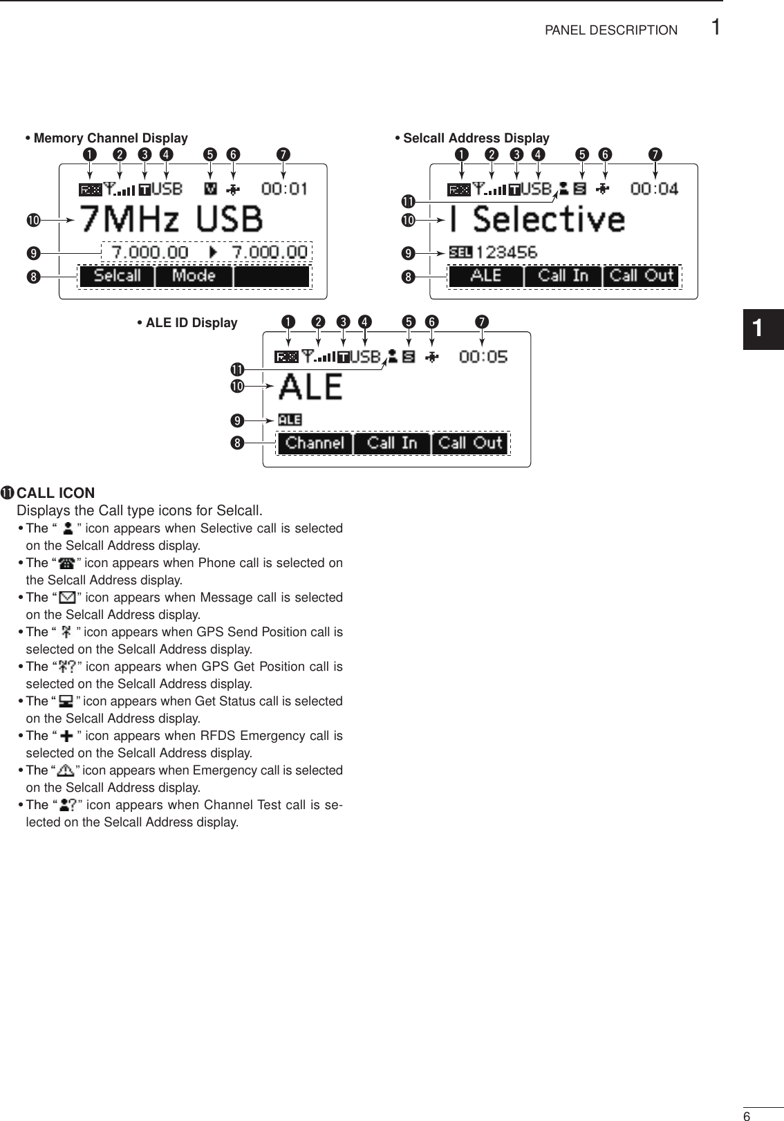
![51PANEL DESCRIPTION2001 NEW 2001 NEWq RECEIVE/TRANSMIT ICON ➥ “ RX” appears when signals are received or the squelch is open. ➥ “ TX” appears during transmit.w S-METER/TX METERS ➥ Displays the receive signal strength. ➥ Displays the transmit output power. Mic gain can also be displayed when the “METER TYPE” item in the Admin Menu is set to “MIC LEVEL.”e TUNE ICON Appears after the automatic antenna tuner matches the transceiver and antenna.r OPERATING MODE INDICATOR Displays the selected operating mode. • “LSB,” “USB,” “CW,” “AM,” “D1,”* “D2”* or “D3”* appears, depending on the operating mode. * When the “Modem” setting in the Admin Menu is set to “OFF,” “RTTY” appears instead. (p. 40) The D1, D2 or D3 mode can be set in the “Data mode 1,” “Data mode 2” or “Data mode 3” settings in the Admin Menu. (p. 40)t MUTE ICON ➥ “S” appears when the Call squelch function is se-lected. ➥ “L” appears when the S-meter squelch is se-lected. ➥ “V” appears when the Voice squelch is selected.y GPS ICON Appears when valid position data is received from a GPS receiver that is connected to the AD-119 or OPC-2205. u TIME DISPLAY Displays time data.i FUNCTION DISPLAY Displays the function of the function keys ([§], [§§] and [§§§]).o SUB READOUTS <Memory Channel display> Shows the channel transmit and receive frequen-cies. The receive frequency is displayed on the right and the transmit frequency is displayed on the left. NOTE: The transmit frequency is not displayed when the selected channel is configured as “re-ceive only.” <Selcall Address display> Shows the Selcall ID or phone number of the call. <ALE ID display> Displays the NET ID for ALE transmissions.!0 MAIN READOUTS <Memory Channel display> Displays the channel name. <Selcall Address display> Shows the Selcall Address of the call. <ALE ID display> Shows the ALE ID for ALE transmission.::• Memory Channel Display • Selcall Address Display• ALE ID Displayq w r t y u q w r t y uq w re ee t y uo!0o!0!1!1o!0i ii■ LCD screen](https://usermanual.wiki/ICOM-orporated/329600/User-Guide-1729805-Page-10.png)
![2001 NEW71PANEL DESCRIPTION2001 NEWq DATA JACK [DATA] Connects to a PC through an RS-232C cable (D-sub 9-pin) for remote control in the RS-232C for-mat.w GPS CONNECTOR [GPS] Connects to a GPS receiver to automatically set your position and time data from data in NMEA0183 ver. 2.0 or 3.01 formats.e GPIO CONNECTOR [GPIO] Connects to the control cable of the optional AT-140 Antenna Tuner or AT230 Automatic Tuning An-tenna.q USB CONNECTOR [USB] Connects to a PC through an A-B type USB cable.w ACCESSORY CONNECTOR 2 (12 PIN) [ACC2]e ACCESSORY CONNECTOR 1 (10 PIN) [ACC1] Connects to the IC-F8100’s Accessory connectors. Both connectors must be connected to use this Junction Box.r GROUND TERMINAL IMPORTANT! Connects to a solid ground point.t EXTERNAL MODEM CONNECTOR [EXT. MODEM] Connects to an external unit such as an HF email modem or TNC (Terminal Node Controller). NOTE: This connector may not be available, de-pending on the AD-119’s version.q w e■ AD-119 Optional Junction BoxD Front Panelqtw e rD Rear Panel](https://usermanual.wiki/ICOM-orporated/329600/User-Guide-1729805-Page-12.png)
![28BASIC OPERATION2001 NEW1234567891011121314151617Quick Reference➥ Push [ ] to turn ON the Power. • Built-in Test is displayed. The BIT display can be turned OFF in the Advance Menu. • Hold down [] for 2 seconds to turn OFF the power.■ Power ONq Push [§] one or more times to select the Memory Channel display. • The display sequentially selects “Channel” ➪“Selcall” ➪“ALE” ➪“Channel.”w Push [r] or [s] to select a desired memory chan-nel.•••➥ Push [§] one or more times to select a desired dis-play mode. • The display sequentially selects “Channel” ➪“Selcall” ➪“ALE” ➪“Channel.”Memory channel displaySelcall Address displayALE ID display■ Selecting a channel■ Selecting display mode](https://usermanual.wiki/ICOM-orporated/329600/User-Guide-1729805-Page-13.png)
 one or more times to select a squelch type. Selectable types are Call SQL, S-meter SQL (level 1 to 50), Voice SQL and OFF. • The S-meter squelch level can be adjusted in “Squelch Level” in the User Menu.Mute icon • The Mute icon, “S,” “L” or “V,” appears when the squelch function is turned ON.➥ Push [ +] or [ –] to adjust the audio level. • If the squelch is closed, push [MUTE](M) one or more times to open the squelch. • The display shows the volume level while adjusting. Minimum audio level•••Maximum audio level■ Squelch function■ Setting audio volumeThe scan function repeatedly scans programmed channels. This function is convenient to wait for calls on multiple channels.[Stop]q Push [SCAN](#) to start a scan.• “Scanning” and the Scan type are displayed.w When a signal is received, the scan pauses on that channel.e Push [Stop](§§) to cancel the scan.• Pushing [SCAN](#) also cancels the scan. NOTE: The scan resume setting (the action after receiving a signal) can be changed in “Scan Re-sume” in the Admin Menu. (p. 41)■ Scan function](https://usermanual.wiki/ICOM-orporated/329600/User-Guide-1729805-Page-14.png)
![2001 NEW102BASIC OPERATION1234567891011121314151617Quick ReferenceThe following modes are selectable in the IC-F8100:LSB, USB, CW, AM, D1,* D2* and D3.** When the “Modem” setting in the Admin Menu is set to “OFF,” “RTTY” can be selected instead. (p. 40) The D1, D2 or D3 mode can be set in the “Data mode 1,” “Data mode 2” or “Data mode 3” settings in the Admin Menu. (p. 40)[Mode]q Push [§] one or more times to select the Memory Channel display. • The display sequentially selects “Channel” ➪“Selcall” ➪“ALE” ➪“Channel.”w Push [Mode](§§) one or more times to select the desired mode. • The selected mode icon appears at the top of the display. NOTE: • The selected mode can be used only temporarily. When the channel is changed, it returns to the preprogrammed operating mode. • Depending on the transceiver version or prepro-gramming, some operating modes may not be selectable or usable except receive.To prevent accidental channel changes, or unneces-sary function access, use the Key Lock function. The transceiver has two types of Key Lock functions.[Default] [][]/q Hold down [MENU](HOME) for 1 second to enter the Menu screen.w Push [r] or [s] to select the “User Menu,” and then push [4].e Push [r] or [s] to select “Key Lock.”r Push [t](§) or [u](§§§) to select the Key Lock function, “ALL” or “NUMERIC KEY.” • Hold down [Default](§§) for 1 second to return to the default setting.t Push [MENU](HOME) twice to return to the nor-mal operating screen.• To turn OFF the functionWhen you push the locked key, “Numeric Key Locked” or “All Key Locked” appears, depending on the func-tion. Then push [Unlock](§§) to turn OFF the func-tion.■ Mode selection■ Key Lock function](https://usermanual.wiki/ICOM-orporated/329600/User-Guide-1729805-Page-15.png)
 to turn the VFO mode ON or OFF.• Frequency setting q Push [A/B](§) to select VFO A or VFO B. w Push [4] to enter the frequency setting mode. e Push [t](§) or [u](§§§) to move the cursor to se-lect the desired digit to change. • The cursor is displayed below the selected digit. r Push [r] or [s] to change the frequency. t Push [4] to exit the frequency setting mode.• Turning ON the split frequency function q Push [A/B](§) to select VFO A or VFO B, and separately set the receive and transmit frequen-cies. w Push [Split](§§§) to turn the split frequency func-tion ON. • The TX frequency appears below the RX frequency. • Pushing [A/B](§) changes the VFOs between trans-mit and receive. e To turn OFF the split frequency function, push [Split](§§§) again.[��][���][�]/■ VFO operation](https://usermanual.wiki/ICOM-orporated/329600/User-Guide-1729805-Page-16.png)
 one or more times to turn OFF the mute.Mute iconw Push [r] or [s] to select the desired receive chan-nel. • The S-meter shows signal strength when signal is re-ceived.e Push [ +] or [ –] to adjust a desired audio level when receiving a signal. • If the bass or treble of the receive audio is too strong, set “Clarifier” to ON in the User Menu, and adjust to ob-tain clear audio. (See page 15 for the Clarifier function details.) • If the audio is distorted, select the suitable operating mode. (See page 10 for the Mode selection details.)r Push [TUNER](9) once or twice to enter the an-tenna tune mode. • The “Auto Tune” or “Manual Tune” screen sequentially appears. When the transceiver is connected to an optional antenna tuner and “Auto Tune” screen is selected, push [4] to start auto tuning. • The display shows the antenna SWR. • If the antenna cannot be tuned after 20 seconds, the tuning circuit is automatically bypassed. • After tuning is finished, the auto tune automatically stops transmitting. • Push [8] to manually stop transmitting, if necessary. • Push [Through](§§) to turn OFF the AT-140 (bypass). When the transceiver is connected to another an-tenna tuner, or directly connected to an antenna and the “Manual Tune” screen is selected, push [4] to start transmitting and tune the antenna. • The display shows the antenna SWR. • Push [8] to stop transmitting.t After tuning is finished, push [TUNER](9) once or twice to return to the normal operating screen.y To transmit on the channel, hold down [PTT] on the microphone, and speak at a normal voice level. • The RF meter shows the output power.u Release [PTT] to receive.](https://usermanual.wiki/ICOM-orporated/329600/User-Guide-1729805-Page-17.png)
![■ Functions for transmitï Transmit power selectionThe transceiver has three output power levels, HIGH, MID and LOW. High power provides longer distance communications and low power reduces power con-sumption.[Default] [][]/q Hold down [MENU](HOME) for 1 second to enter the Menu screen.w Push [r] or [s] to select the “User Menu,” and then push [4].e Push [r] or [s] to select “RF Power.”r Push [t](§) or [u](§§§) to select the desired out-put power. • Hold down [Default](§§) for 1 second to return to the default setting.t Push [MENU](HOME) twice to return to the nor-mal operating screen.ï Setting Microphone gainThe microphone gain must be properly adjusted so that your signal is not distorted when transmitted.[Default] [][]/q Hold down [MENU](HOME) for 1 second to enter the Menu screen.w Push [r] or [s] to select the “User Menu,” and then push [4].e Push [r] or [s] to select “Mic Gain.”r Push [t](§) or [u](§§§) to select the desired Mic gain. • Hold down [Default](§§) for 1 second to return to the default setting.t Push [MENU](HOME) twice to return to the nor-mal operating screen.133RECEIVE AND TRANSMIT2001 NEW 2001 NEW](https://usermanual.wiki/ICOM-orporated/329600/User-Guide-1729805-Page-18.png)
![143RECEIVE AND TRANSMIT3ï Checking the MIC levelThe transceiver has a MIC level meter. You can check the MIC level before or after adjusting the Microphone gain.[Default] [][]/q Hold down [MENU](HOME) for 1 second to enter the Menu screen.w Push [r] or [s] to select the “Admin Menu,” and then push [4].e Push [r] or [s] to select “Meter Type.”r Push [u](§§§) to select “MIC LEVEL.”t Push [MENU](HOME) twice to return to the nor-mal operating screen.y Hold down [PTT] on the microphone, and speak at a normal voice level.u While speaking into the microphone, check the TX meter reading.ï Speech ProcessorThe IC-F8100 has a built-in, low distortion Speech Processor circuit. This circuit increases your average talk power in the SSB mode and is especially useful when the receiving station is having difficulty hearing your audio.[Default] [][]/q Hold down [MENU](HOME) for 1 second to enter the Menu screen.w Push [r] or [s] to select the “User Menu,” and then push [4].e Push [r] or [s] to select “Speech Processor.”r Push [t](§) or [u](§§§) to turn the Speech proces-sor function ON or OFF. • Hold down [Default](§§) for 1 second to return to the default setting.t Push [MENU](HOME) twice to return to the nor-mal operating screen.y Push [Mode](§§) one or more times to select the USB or LSB mode.u Hold down [PTT] on the microphone, and speak at a normal voice level.2001 NEW](https://usermanual.wiki/ICOM-orporated/329600/User-Guide-1729805-Page-19.png)
![153RECEIVE AND TRANSMIT2001 NEW 2001 NEW■ Functions for receiveï Clarifier functionThe Clarifier function compensates for off-frequency stations. The function shifts the receive frequency up to ±200 Hz, without moving the transmit frequency.• Setting[�]/q Hold down [MENU](HOME) for 1 second to enter the Menu screen.w Push [r] or [s] to select the “User Menu,” and then push [4].e Push [r] or [s] to select “Clarifier.”r Push [u](§§§) to turn ON the Clarifier function.t Push [MENU](HOME) twice to return to the nor-mal operating screen.• Operation[��][���][�]/Upper shiftLower shiftq Push [CLAR](7) to turn ON the Clarifier function.w Push [–](§) or [+](§§§) to tune the frequency shift. • The transmit frequency is not shifted. • Hold down [Clear](§§) for 1 second to return to the center position, if desired. When cancelling the Clarifier function, push [CLAR](7) again.](https://usermanual.wiki/ICOM-orporated/329600/User-Guide-1729805-Page-20.png)
![316RECEIVE AND TRANSMIT32001 NEWï Preamp and AttenuatorThe preamp amplifies received signals in the front end circuit to improve the S/N ratio and sensitivity. Turn ON this function to better receive weak signals.The attenuator prevents strong undesired signals near the desired frequency or near your location, such as from a broadcast station, from causing dis-tortion or spurious signals.[][]/q Hold down [MENU](HOME) for 1 second to enter the Menu screen.w Push [r] or [s] to select the “User Menu,” and then push [4].e Push [r] or [s] to select “Pre Amp.”r Push [t](§) or [u](§§§) to turn ON the Preamp or Attenuator function.t Push [MENU](HOME) twice to return to the nor-mal operating screen.ï Noise BlankerThe noise blanker reduces pulse-type noise such as that generated by automobile ignition systems.The noise blanker may distort reception of strong signals. In such cases, the noise blanker should be turned OFF.[][]/q Hold down [MENU](HOME) for 1 second to enter the Menu screen.w Push [r] or [s] to select the “User Menu,” and then push [4].e Push [r] or [s] to select “Noise Blanker.”r Push [u](§§§) to turn ON the Noise Blanker func-tion.t Push [s] to select “Blanker Level.”y Push [t](§) or [u](§§§) to adjust the noise blanker level.u Push [MENU](HOME) twice to return to the nor-mal operating screen. When using the noise blanker, received signals may be distorted if they are excessively strong.](https://usermanual.wiki/ICOM-orporated/329600/User-Guide-1729805-Page-21.png)
![173RECEIVE AND TRANSMIT2001 NEW 2001 NEW■ Functions for receive (Continued)D AGC functionThe AGC (automatic gain control) controls receiver gain to produce a constant audio output level, even when the received signal strength varies by fading, and so on.The transceiver has two AGC characteristics; AUTO and time constants FAST and SLOW. [][]/q Hold down [MENU](HOME) for 1 second to enter the Menu screen.w Push [r] or [s] to select the “User Menu,” and then push [4].e Push [r] or [s] to select “AGC.”r Push [t](§) or [u](§§§) to select the desired AGC time constant, FAST, SLOW or AUTO. When AUTO is selected, the AGC time constant varies, depending on the operating mode.t Push [MENU](HOME) twice to return to the nor-mal operating screen.D AGC OFF functionWhen receiving weak signals with adjacent strong signals or noise, the AGC function may reduce the sensitivity. In this situation, the AGC function should be turned OFF.[�]/q Hold down [MENU](HOME) for 1 second to enter the Menu screen.w Push [r] or [s] to select the “Admin Menu,” and then push [4].e Push [r] or [s] to select “AGC.”r Push [t](§) to turn OFF the AGC function.t Push [MENU](HOME) twice to return to the nor-mal operating screen.](https://usermanual.wiki/ICOM-orporated/329600/User-Guide-1729805-Page-22.png)
 to turn the Clear Talk function ON or OFF. • “C” appears when the Clear Talk function is ON.Appearsï IF Filter selectionThe transceiver has three passband IF filter widths for each mode.[][]/q Hold down [MENU](HOME) for 1 second to enter the Menu screen.w Push [r] or [s] to select the “User Menu,” and then push [4].e Push [r] or [s] to select “Bandwidth”y Push [t](§) or [u](§§§) to select the IF filter width, NARROW, MID or WIDE.u Push [MENU](HOME) twice to return to the nor-mal operating screen.](https://usermanual.wiki/ICOM-orporated/329600/User-Guide-1729805-Page-23.png)
![204SELCALL/ALE OPERATION4The Selcall function allows you to make individual or group calls. Each transceiver is assigned an individual ID (identification) and can be called using this ID.• Preparation for Selective callSend a Channel Test call on several Selcall channels, and check the propagation on each one to select the channel with the best signal quality. (p. 30)• Sending Selective callq With the Memory Channel displayed, push [] to enter the Call select menu.w Push [t](§) or [u](§§§) to set the Call to “SEL-CALL,” then push [ ] to enter the Selcall menu.e Push [t](§) or [u](§§§) to set the Call type to “SE-LECTIVE.” • “SELECTIVE,” “PHONE,” “MESSAGE,” “SEND POSITION,” “GET POSITION,” “GET STATUS,” “EMERGENCY” and “CHANNEL TEST” are selectable.r Push [ ] to go to the next screen. • Push [HOME] to return to the previous screen. ❍ Call ID input Push the numeric keys to enter the Call ID. • Push [8] to delete the number. • This Call ID is not stored in the Call ID list. ❍ Call ID selection ➥ Push [List](§§) to enter the list selection mode. ➥ Push [t](§) or [u](§§§) to select the Call ID. • Push [Edit](§§) to return to the direct input mode.t Push [ ] to go to the next screen. • Push [HOME] to return to the previous screen. ❍ Network selection Push [t](§) or [u](§§§) to select the Network.y Push [ ] to go to the next screen. • Push [HOME] to return to the previous screen. ❍ Self ID selection Push [t](§) or [u](§§§) to select the Self ID. ❍ Self ID input ➥ Push [Edit](§§) to enter the direct input mode. ➥ Push the numeric keys to enter the Self ID. • Push [8] to delete the number. • This Self ID is overwritten or stored in the Self ID list. • Push [List](§§) to return to the list selection mode.u Push [ ] to enter the Channel Menu, and then push [t](§) or [u](§§§) to select the desired operat-ing channel. • Push [HOME] to return to the Selcall menu.i Push [ ] to transmit the Selective call. The call is stored in the Call Out memory. • While calling, push [PTT] to cancel the call. You can also transmit a Selective call when the Sel-call Address is displayed. In this case, you can skip steps q to t above, after selecting the Selective call address.• Receiving Selective callsWhen a transceiver receives a Selective call with your individual ID, it automatically responds by transmitting. The received Selcall is stored in the Call In memory.q After receiving a Selective call, and push any key to enter the Call In memory screen.w Push [More](§§§) or [Prev](§) to select the informa-tion.e Push [Home] to return to the normal operating screen.ï Selective call](https://usermanual.wiki/ICOM-orporated/329600/User-Guide-1729805-Page-25.png)
![214SELCALL/ALE OPERATION2001 NEW 2001 NEWAllows you to make Phone calls through a telephone interconnect service provider.• Preparation for Phone callSend a Channel Test call on several Phone call chan-nels, and check the propagation on each one to select the channel with the best signal quality. (p. 30)• Sending Phone callq With the Memory Channel displayed, push [] to enter the Call select menu.w Push [t](§) or [u](§§§) to set the Call to “SEL-CALL,” then push [ ] to enter the Selcall menu.e Push [t](§) or [u](§§§) to set the Call type to “PHONE.” • “SELECTIVE,” “PHONE,” “MESSAGE,” “SEND PO-SITION,” “GET POSITION,” “GET STATUS,” “EMER-GENCY” and “CHANNEL TEST” are selectable.r Push [ ] to go to the next screen. • Push [HOME] to return to the previous screen. ❍ Phone number input Push the numeric keys to enter the Phone num-ber. • Push [8] to delete the number. • This Number is not stored in the Phone address list. ❍ Phone address selection ➥ Push [List](§§) to enter the list selection mode. ➥ Push [t](§) or [u](§§§) to select the Phone address. • Push [Edit](§§) to return to the direct input mode.t Push [ ] to go to the next screen. • Push [HOME] to return to the previous screen. ❍ Phone Link selection Push [t](§) or [u](§§§) to select the Network. ❍ Phone Link input ➥ Push [Edit](§§) to enter the direct input mode. ➥ Push the numeric keys to enter the Phone Link. • Push [8] to delete the number. • This Phone Link is not stored in the Phone Link list. • Push [List](§§) to return to the list selection mode.y Push [ ] to go to the next screen. • Push [HOME] to return to the previous screen. ❍ Network selection Push [t](§) or [u](§§§) to select the Network.u Push [ ] to go to the next screen. • Push [HOME] to return to the previous screen. ❍ Self ID selection Push [t](§) or [u](§§§) to select the Self ID. ❍ Self ID input ➥ Push [Edit](§§) to enter the direct input mode. ➥ Push the numeric keys to enter the Self ID. • Push [8] to delete the number. • This Self ID is overwritten or stored in the Self ID list. • Push [List](§§) to return to the list selection mode.ï Phone call](https://usermanual.wiki/ICOM-orporated/329600/User-Guide-1729805-Page-26.png)
![224SELCALL/ALE OPERATION42001 NEWi Push [ ] to enter the Channel Menu, and then push [t](§) or [u](§§§) to select the desired operat-ing channel. • Push [HOME] to return to Selcall menu.o Push [ ] to transmit the Phone call. The call is stored in the Call Out memory. • While calling, push [PTT] to cancel the call. You can also transmit a Phone call when the Selcall Address is displayed. In this case, you can skip steps q to r above, after selecting the Phone call address.• After a Phone callq When a Phone call is finished, push [] to enter the Selcall menu. • “TEL DISCONNECT” appears. • If desired, push [HOME] to return to the previous screen.w Then, push [ ] to transmit the disconnect call. • Until ‘TEL DISCONNECT’ is transmitted, the telephone interconnect service provider continues counting the time for toll charging.](https://usermanual.wiki/ICOM-orporated/329600/User-Guide-1729805-Page-27.png)
![234SELCALL/ALE OPERATION2001 NEW 2001 NEWThe Message call allows you to exchange text mes-sages of up to 64 characters,* with the intended ID station, and also leave a message at the station. * 64 characters for ICOM Selcall system; 32 charac-ters for Open Selcall system. • Preparation for Message callSend a Channel Test call on several Phone call chan-nels, and check the propagation on each one to select the channel with the best signal quality. (p. 30)• Sending Message callq With the Memory Channel displayed, push [] to enter the Call select menu.w Push [t](§) or [u](§§§) to set the Call to “SEL-CALL,” then push [ ] to enter the Selcall menu.e Push [t](§) or [u](§§§) to set the Call type to “MES-SAGE.” • “SELECTIVE,” “PHONE,” “MESSAGE,” “SEND PO-SITION,” “GET POSITION,” “GET STATUS,” “EMER-GENCY” and “CHANNEL TEST” are selectable.r Push [ ] to go to the next screen. • Push [HOME] to return to the previous screen. ❍ Call ID input Push the numeric keys to enter the Call ID. • Push [8] to delete the number. • This Call ID is not stored in the Call ID list. ❍ Call ID selection ➥ Push [List](§§) to enter the list selection mode. ➥ Push [t](§) or [u](§§§) to select the Call ID. • Push [Edit](§§) to return to the direct input mode.t Push [ ] to go to the next screen. • Push [HOME] to return to the previous screen. ❍ Message selection Push [t](§) or [u](§§§) to select the Message. ❍ Message input ➥ Push [Edit](§§) to enter the direct input mode. ➥ Push the numeric keys to enter the Message. • Push [A/a](#) to select the character group, ABC (Upper case letters), abc (lower case letters) or 123 (numbers). • Push [8] to delete the character. • This Message is overwritten or stored in the Mes-sage list. • Push [List](§§) to return to the list selection mode.y Push [ ] to go to the next screen. • Push [HOME] to return to the previous screen. ❍ Network selection Push [t](§) or [u](§§§) to select the Network.u Push [ ] to go to the next screen. • Push [HOME] to return to the previous screen. ❍ Self ID selection Push [t](§) or [u](§§§) to select the Self ID. ❍ Self ID input ➥ Push [Edit](§§) to enter the direct input mode. ➥ Push the numeric keys to enter the Self ID. • Push [8] to delete the number. • This Self ID is overwritten or stored in the Self ID list. • Push [List](§§) to return to the list selection mode.i Push [ ] to enter the Channel Menu, and then push [t](§) or [u](§§§) to select the desired operat-ing channel. • Push [HOME] to return to the Selcall menu.o Push [ ] to transmit the Message call. The call is stored in the Call Out memory. • While calling, push [PTT] to cancel the call. You can also transmit a Selective call when the Sel-call Address is displayed. In this case, you can skip steps q to y above, after selecting the Message call address.ï Message call](https://usermanual.wiki/ICOM-orporated/329600/User-Guide-1729805-Page-28.png)
 or [Prev](§) to select the informa-tion.e Push [HOME] to return to the normal operating screen.](https://usermanual.wiki/ICOM-orporated/329600/User-Guide-1729805-Page-29.png)
![254SELCALL/ALE OPERATION2001 NEW 2001 NEWThe Send Position call allows you to send your own position/time information to the intended ID station.• Preparation for Send Position callSend a Channel Test call on several Phone call chan-nels, and check the propagation on each one to select the channel with the best signal quality. (p. 30)• Sending Send Position callq With the Memory Channel displayed, push [] to enter the Call select menu.w Push [t](§) or [u](§§§) to set the Call to “SEL-CALL,” then push [ ] to enter the Selcall menu.e Push [t](§) or [u](§§§) to set the Call type to “SEND POSITION.” • “SELECTIVE,” “PHONE,” “MESSAGE,” “SEND PO-SITION,” “GET POSITION,” “GET STATUS,” “EMER-GENCY” and “CHANNEL TEST” are selectable.r Push [ ] to go to the next screen. • Push [HOME] to return to the previous screen. ❍ Call ID input Push the numeric keys to enter the Call ID. • Push [8] to delete the number. • This Call ID is not stored in the Call ID list. ❍ Call ID selection ➥ Push [List](§§) to enter the list selection mode. ➥ Push [t](§) or [u](§§§) to select the Call ID. • Push [Edit](§§) to return to the direct input mode.t Push [ ] to go to the next screen. • Push [HOME] to return to the previous screen. ❍ Network selection Push [t](§) or [u](§§§) to select the Network.y Push [] to go to the next screen. • Push [HOME] to return to the previous screen. ❍ Self ID selection Push [t](§) or [u](§§§) to select the Self ID. ❍ Self ID input ➥ Push [Edit](§§) to enter the direct input mode. ➥ Push the numeric keys to enter the Self ID. • Push [8] to delete the number. • This Self ID is overwritten or stored in the Self ID list. • Push [List](§§) to return to the list selection mode.u Push [ ] to enter the Channel Menu, and then push [t](§) or [u](§§§) to select the desired operat-ing channel. • Push [HOME] to return to the Selcall menu.i Push [ ] to transmit the Send Position call. The call is stored in the Call Out memory. • While calling, push [PTT] to cancel the call. You can also transmit a Send Position call when the Selcall Address is displayed. In this case, you can skip steps q to t above, after selecting the Send Position call address.• Receiving a Send Position callWhen a transceiver receives a Send Position call with your individual ID, it automatically responds by trans-mitting. The received Send Position call is stored in the Call In memory.q After receiving a Send Position call, and push any key to enter the Call In memory.w Push [More](§§§) or [Prev](§) to select the informa-tion.e Push [HOME] to return to normal operating screen.ï Send Position call](https://usermanual.wiki/ICOM-orporated/329600/User-Guide-1729805-Page-30.png)
![264SELCALL/ALE OPERATION42001 NEWThe Get Position call allows you to request an intended ID station to send its position information.• Preparation for Get Position callSend a Channel Test call on several Phone call chan-nels, and check the propagation on each one to select the channel with the best signal quality. (p. 30)• Sending Get Position callq With the Memory Channel displayed, push [] to enter the Call select menu.w Push [t](§) or [u](§§§) to set the Call to “SEL-CALL,” then push [ ] to enter the Selcall menu.e Push [t](§) or [u](§§§) to set the Call type to “GET POSITION.” • “SELECTIVE,” “PHONE,” “MESSAGE,” “SEND PO-SITION,” “GET POSITION,” “GET STATUS,” “EMER-GENCY” and “CHANNEL TEST” are selectable.r Push [ ] to go to the next screen. • Push [HOME] to return to the previous screen. ❍ Call ID input Push the numeric keys to enter the Call ID. • Push [8] to delete the number. • This Call ID is not stored in the Call ID list. ❍ Call ID selection ➥ Push [List](§§) to enter the list selection mode. ➥ Push [t](§) or [u](§§§) to select the Call ID. • Push [Edit](§§) to return to the direct input mode.t Push [ ] to go to the next screen. • Push [HOME] to return to the previous screen. ❍ Network selection Push [t](§) or [u](§§§) to select the Network.y Push [ ] to go to the next screen. • Push [HOME] to return to the previous screen. ❍ Self ID selection Push [t](§) or [u](§§§) to select the Self ID. ❍ Self ID input ➥ Push [Edit](§§) to enter the direct input mode. ➥ Push the numeric keys to enter the Self ID. • Push [8] to delete the number. • This Self ID is overwritten or stored in the Self ID list. • Push [List](§§) to return to the list selection mode.u Push [ ] to enter the Channel Menu, and then push [t](§) or [u](§§§) to select the desired operat-ing channel. • Push [HOME] to return to the Selcall menu.i Push [ ] to transmit the Get Position call. The call is stored in the Call Out memory. • While calling, push [PTT] to cancel the call. You can also transmit a Get Position call when the Selcall Address is displayed. In this case, you can skip steps q to t above, after selecting the Get Position call address.• Receiving a Get Position call acknowledgementq After the call is transmitted, your called station sends position/time information as an acknowledge-ment. Push [] to enter the Call In memory.w Push [More](§§§) or [Prev](§) to select the informa-tion.e Push [HOME] to return to the normal operating screen.• Receiving a Get Position callWhen your transceiver receives a Get Position call that includes your individual ID, it automatically responds by transmitting. ï Get Position call](https://usermanual.wiki/ICOM-orporated/329600/User-Guide-1729805-Page-31.png)
![274SELCALL/ALE OPERATION2001 NEW 2001 NEWThe Get Status call requests sending radio status infor-mation including power supply voltage, signal strength, output power, VSWR, and so on.• Preparation for Get Status callSend a Channel Test call on several Phone call chan-nels, and check the propagation on each one to select the channel with the best signal quality. (p. 30)• Sending Get Status callq With the Memory Channel displayed, push [] to enter the Call select menu.w Push [t](§) or [u](§§§) to set the Call to “SEL-CALL,” then push [ ] to enter the Selcall menu.e Push [t](§) or [u](§§§) to set the Call type to “GET STATUS.” • “SELECTIVE,” “PHONE,” “MESSAGE,” “SEND PO-SITION,” “GET POSITION,” “GET STATUS,” “EMER-GENCY” and “CHANNEL TEST” are selectable.r Push [ ] to go to the next screen. • Push [HOME] to return to the previous screen. ❍ Call ID input Push the numeric keys to enter the Call ID. • Push [8] to delete the number. • This Call ID is not stored in the Call ID list. ❍ Call ID selection ➥ Push [List](§§) to enter the list selection mode. ➥ Push [t](§) or [u](§§§) to select the Call ID. • Push [Edit](§§) to return to the direct input mode.t Push [ ] to go to the next screen. • Push [HOME] to return to the previous screen. ❍ Network selection Push [t](§) or [u](§§§) to select the Network.y Push [] to go to the next screen. • Push [HOME] to return to the previous screen. ❍ Self ID selection Push [t](§) or [u](§§§) to select the Self ID. ❍ Self ID input ➥ Push [Edit](§§) to enter the direct input mode. ➥ Push the numeric keys to enter the Self ID. • Push [8] to delete the number. • This Self ID is overwritten or stored in the Self ID list. • Push [List](§§) to return to the list selection mode.u Push [ ] to enter the Channel Menu, and then push [t](§) or [u](§§§) to select the desired operat-ing channel. • Push [HOME] to return to the Selcall menu.i Push [ ] to transmit the Get Status call. The call is stored in the Call Out memory. • While calling, push [PTT] to cancel the call. You can also transmit a Get Status call when the Selcall Address is displayed. In this case, you can skip steps q to t above, after selecting the Get Status call address.• Receiving a Get Status call acknowledgementq After the call is transmitted, your called station sends status information as an acknowledgement. Push any key to enter the Call In memory.w Push [More](§§§) or [Prev](§) to select the informa-tion. • Status information includes power supply voltage and signal strength.e Push [HOME] to return to the normal operating screen.• Receiving a Get Status callWhen a transceiver receives a Get Status call that in-cludes your individual ID, it automatically responds by transmitting. ï Get Status call](https://usermanual.wiki/ICOM-orporated/329600/User-Guide-1729805-Page-32.png)
![284SELCALL/ALE OPERATION42001 NEWThe RFDS (Royal Flying Doctor Service) emergency call uses a 2-Tone signal for an emergency call.• Sending RFDS emergency callq With the Memory Channel displayed, push [] to enter the Call select menu.w Push [t](§) or [u](§§§) to set the Call to “SEL-CALL,” then push [ ] to enter the Selcall menu.e Push [t](§) or [u](§§§) to set the Call type to “RFDS EMERGENCY.” • “SELECTIVE,” “PHONE,” “MESSAGE,” “SEND PO-SITION,” “GET POSITION,” “GET STATUS,” “EMER-GENCY,” “CHANNEL TEST” and “RFDS EMERGENCY” are selectable.r Push [ ] to enter the Channel Menu, and then push [t](§) or [u](§§§) to select the desired operat-ing channel. • Push [HOME] to return to the Selcall menu.t Push [ ] to transmit the RFDS emergency call. The call is stored in the Call Out memory. • While calling, push [PTT] to cancel the call. You can also transmit an RFDS emergency call when the Selcall Address is displayed. In this case, you can skip steps q to e above, after selecting the RFDS emergency call address.ï RFDS emergency call (only AUS versions)](https://usermanual.wiki/ICOM-orporated/329600/User-Guide-1729805-Page-33.png)
![294SELCALL/ALE OPERATION2001 NEW 2001 NEWThe Emergency call allows you to broadcast an emer-gency signal with your own position information.• Sending Emergency callq With the Memory Channel displayed, push [] to enter the Call select menu.w Push [t](§) or [u](§§§) to set the Call to “SEL-CALL,” then push [ ] to enter the Selcall menu.e Push [t](§) or [u](§§§) to set the Call type to “EMERGENCY.” • “SELECTIVE,” “PHONE,” “MESSAGE,” “SEND PO-SITION,” “GET POSITION,” “GET STATUS,” “EMER-GENCY” and “CHANNEL TEST” are selectable.r Push [ ] to go to the next screen. • Push [HOME] to return to the previous screen. ❍ Call ID input Push the numeric keys to enter the Call ID. • Push [8] to delete the number. • This Call ID is not stored in the Call ID list. ❍ Call ID selection ➥ Push [List](§§) to enter the list selection mode. ➥ Push [t](§) or [u](§§§) to select the Call ID. • Push [Edit](§§) to return to the direct input mode.t Push [ ] to go to the next screen. • Push [HOME] to return to the previous screen. ❍ Network selection Push [t](§) or [u](§§§) to select the Network.y Push [ ] to go to the next screen. • Push [HOME] to return to the previous screen. ❍ Self ID selection Push [t](§) or [u](§§§) to select the Self ID. ❍ Self ID input ➥ Push [Edit](§§) to enter the direct input mode. ➥ Push the numeric keys to enter the Self ID. • Push [8] to delete the number. • This Self ID is overwritten or stored in the Self ID list. • Push [List](§§) to return to the list selection mode.u Push [ ] to enter the Channel Menu, and then push [t](§) or [u](§§§) to select the desired operat-ing channel. • Push [HOME] to return to the Selcall menu.i Push [ ] to transmit the Emergency call. The call is stored in the Call Out memory. • While calling, push [PTT] to cancel the call. You can also transmit an Emergency call when the Selcall Address is displayed. In this case, you can skip steps q to t above, after selecting the Emer-gency call address.• Receiving an Emergency CallWhen your transceiver receives an Emergency Call with your individual ID, it automatically responds by transmitting. The received Emergency Call is stored in the Call In memory.q After receiving a Emergency call, and push any key to enter the Call In memory.w Push [More](§§§) or [Prev](§) to select the informa-tion.e Push [HOME] to return to normal operating screen.ï Emergency selcall](https://usermanual.wiki/ICOM-orporated/329600/User-Guide-1729805-Page-34.png)
![304SELCALL/ALE OPERATION42001 NEWThe Channel Test call allows the user determine the signal quality between your transceiver and a spe-cific transceiver before an individual or group call. The Channel Test call is also used for checking the channel before sending a Phone call.• Sending Channel Test callq With the Memory Channel displayed, push [] to enter the Call select menu.w Push [t](§) or [u](§§§) to set the Call to “SEL-CALL,” then push [ ] to enter the Selcall menu.e Push [t](§) or [u](§§§) to set the Call type to “CHANNEL TEST.” • “SELECTIVE,” “PHONE,” “MESSAGE,” “SEND POSITION,” “GET POSITION,” “GET STATUS,” “EMERGENCY” and “CHANNEL TEST” are selectable.r Push [ ] to go to the next screen. • Push [HOME] to return to the previous screen. ❍ Call ID input Push the numeric keys to enter the Call ID. • Push [8] to delete the number. • This Call ID is not stored in the Call ID list. ❍ Call ID selection ➥ Push [List](§§) to enter the list selection mode. ➥ Push [t](§) or [u](§§§) to select the Call ID. • Push [Edit](§§) to return to the direct input mode.t Push [ ] to go to the next screen. • Push [HOME] to return to the previous screen. ❍ Network selection Push [t](§) or [u](§§§) to select the Network.y Push [ ] to go to the next screen. • Push [HOME] to return to the previous screen. ❍ Self ID selection Push [t](§) or [u](§§§) to select the Self ID. ❍ Self ID input ➥ Push [Edit](§§) to enter the direct input mode. ➥ Push the numeric keys to enter the Self ID. • Push [8] to delete the number. • This Self ID is overwritten or stored in the Self ID list. • Push [List](§§) to return to the list selection mode.u Push [ ] to enter the Channel Menu, and then push [t](§) or [u](§§§) to select the desired operat-ing channel. • Push [HOME] to return to the Selcall menu.i Push [ ] to transmit the Channel Test call. The call is stored in the Call Out memory. • While calling, push [PTT] to cancel the call. You can also transmit a Channel test call when the Selcall Address is displayed. In this case, you can skip steps q to t above, after selecting the Chan-nel Test call address.ï Channel Test call](https://usermanual.wiki/ICOM-orporated/329600/User-Guide-1729805-Page-35.png)
![314SELCALL/ALE OPERATION2001 NEW 2001 NEWAutomatically establish a communication link by using the ALE table.• Sending an Individual callq With the Memory Channel displayed, push [] to enter the Call select menu.w Push [t](§) or [u](§§§) to set the Call to “ALE,” then push [ ] to enter the ALE menu.e Push [t](§) or [u](§§§) to set the ALE type to “IN-DIVIDUAL.” • “INDIVIDUAL,” “NET,” “SOUNDING” and “AMD” are se-lectable.r Push [ ] to go to the next screen. • Push [HOME] to return to the previous screen. ❍ ALE ID selection Push [t](§) or [u](§§§) to select the ALE ID.t Push [ ] to go to the next screen. • Push [HOME] to return to the previous screen. ❍ Self ID selection Push [t](§) or [u](§§§) to select Self ID.y Push [ ] to enter the Channel Menu, and then push [t](§) or [u](§§§) to select the desired operat-ing channel. • Push [HOME] to return to the ALE Menu. • When <Auto> is selected, the transceiver automatically selects the best quality channel in sequential order, using the LQA table.u Push [ ] to transmit an Individual call. The call is stored in the Call Out memory. • While calling, push [PTT] to cancel the call. You can also transmit an Individual call when the ALE ID is displayed. In this case, you can skip the Call selection.• After an ALE callq After an ALE call is finished, push any key to enter the ALE menu. • While linking the ALE call, “TERMINATION” appears.w Push [ ] to transmit a disconnect call. • Until ‘TERMINATION’ is transmitted, the channel cannot be changed.• Sending Net callq Set the Call to “ALE,” the same operation as Send-ing Individual call’s steps q and w, to the left.w Push [t](§) or [u](§§§) to set the ALE type to “NET.” • “INDIVIDUAL,” “NET,” “SOUNDING” and “AMD” are se-lectable.e Push [ ] to go to the next screen. • Push [HOME] to return to the previous screen. ❍ ALE ID selection Push [t](§) or [u](§§§) to select an ALE ID for a Net call.r Select the Self ID and Operating channel, the same operation as Sending Individual call’s in steps t and y to the left.t Push [ ] to transmit the Net call. The call is stored in the Call Out memory. • While calling, push [PTT] to cancel the call. You can also transmit a Net call when the ALE ID is displayed. In this case, you can skip the Call selec-tion.ï ALE call](https://usermanual.wiki/ICOM-orporated/329600/User-Guide-1729805-Page-36.png)
![2001 NEW324SELCALL/ALE OPERATION1234567891011121314151617Quick Referenceï ALE soundingAutomatically sends a sounding signal at a certain interval (0.5–16 hours) to check the propagation and stores the data in a table. Manual soundings can also be made.• Manual soundingq With the Memory Channel displayed, push [] to enter the Call select menu.w Push [t](§) or [u](§§§) to set the Call to “ALE,” then push [ ] to enter the ALE menu.e Push [t](§) or [u](§§§) to set the ALE type to “SOUNDING.” • “INDIVIDUAL,” “NET,” “SOUNDING” and “AMD” are se-lectable.r Push [ ] to go to the next screen. • Push [HOME] to return to the previous screen. ❍ Self ID selection Push [t](§) or [u](§§§) to select Self ID.t Push [ ] to enter the Channel Menu, and then push [t](§) or [u](§§§) to select the desired operat-ing channel. • Push [HOME] to return to the ALE Menu.y Push [ ] to transmit the ALE sounding. • While calling, push [PTT] to cancel the call. You can also transmit an ALE sounding when the ALE ID is displayed. In this case, you can skip the Call selection.](https://usermanual.wiki/ICOM-orporated/329600/User-Guide-1729805-Page-37.png)
![334SELCALL/ALE OPERATION2001 NEW 2001 NEW2001 NEWï ALE AMDThe ALE AMD (Automatic Message Display) sends and receives test messages of up to 90 characters.q With the Memory Channel displayed, push [ ] to enter the Call select menu.w Push [t](§) or [u](§§§) to set the Call to “ALE,” then push [ ] to enter the ALE menu.e Push [t](§) or [u](§§§) to set the ALE type to “AMD.” • “INDIVIDUAL,” “NET,” “SOUNDING” and “AMD” are se-lectable.r Push [ ] to go to the next screen. • Push [HOME] to return to the previous screen. ❍ ALE ID selection Push [t](§) or [u](§§§) to select the ALE ID.t Push [ ] to go to the next screen. • Push [HOME] to return to the previous screen. ❍ Self ID selection Push [t](§) or [u](§§§) to select the Self ID.y Push [ ] to go to the next screen. • Push [HOME] to return to the previous screen. ❍ ALE Message selection Push [t](§) or [u](§§§) to select the ALE Mes-sage.u Push [ ] to enter the Channel Menu, and then push [t](§) or [u](§§§) to select the desired operat-ing channel. • Push [HOME] to return to the ALE Menu. • When <Auto> is selected, the transceiver automatically selects the best quality channel in sequential order, using the LQA table.i Push [ ] to transmit an ALE AMD call. The call is stored in the Call Out memory. • While calling, push [PTT] to cancel the call. You can also transmit an ALE AMD when the ALE ID is displayed. In this case, you can skip the Call selection.• Disconnecting an ALE callq After an ALE call is finished, push [] to enter the ALE menu. • While linking the ALE call, “TERMINATION” appears.w Push [ ] to transmit and disconnect the call. • Until ‘TERMINATION’ is transmitted, the channel cannot be changed.](https://usermanual.wiki/ICOM-orporated/329600/User-Guide-1729805-Page-38.png)
 for 1 second to enter the Menu screen.w Push [r] one or more times to select the Edit Menu, and then push [4].e Push [r] once to select the Clock Setting, and then push [4] again.r Push the numeric keys, 0 to 9 to edit the time. • Push [t](§) or [u](§§§) to move the cursor.t Push [4] to save the time.y Push [MENU](HOME) twice to return to the normal operating screen.[][]/q Hold down [MENU](HOME) for 1 second to enter the Menu screen.w Push [r] one or more times to select the Edit Menu, and then push [4].e Push [s] once to select the UTC Offset Setting, and then push [4] again.r Push [t](§) or [u](§§§) to adjust the offset time. • Hold down [Clear](§§) for 1 second to clear the offset time.t Push [4] to save the offset.y Push [MENU](HOME) twice to return to the normal operating screen.[Clear] [][]/](https://usermanual.wiki/ICOM-orporated/329600/User-Guide-1729805-Page-39.png)
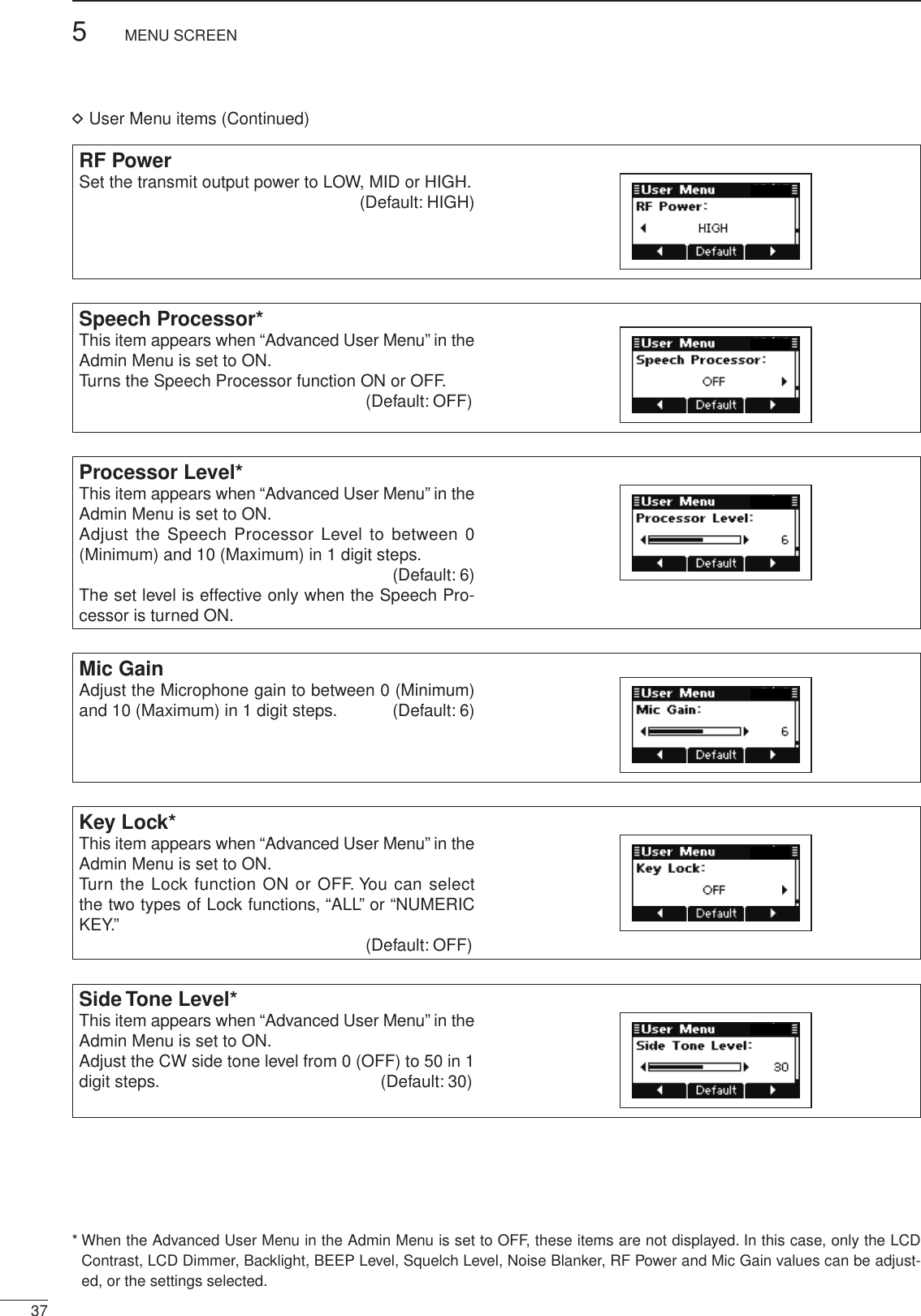
 for 1 second to enter the Menu screen.w Push [r] or [s] to select the User Menu, and then push [4].e Push [r] or [s] to select the desired item.r Push [t](§) or [u](§§§) to adjust or set the value or setting. • Hold down [Default](§§) for 1 second to set the default value or setting.t Push [MENU](HOME) twice to return to the normal operating screen.[Default] [][]/](https://usermanual.wiki/ICOM-orporated/329600/User-Guide-1729805-Page-40.png)
 to turn ON the Clarifier function in the VFO/Memory Channel display.Pre Amp*This item appears when the “Advanced User Menu” in the Admin Menu is set to ON.Turn the receiver Preamplifier function ON or OFF. (Default: ON)When receiving a week signal, turn ON this item.* When the Advanced User Menu in the Admin Menu is set to OFF, these items are not displayed. In this case, only the LCD Contrast, LCD Dimmer, Backlight, BEEP Level, Squelch Level, Noise Blanker, RF Power and Mic Gain values can be adjust-ed, or the settings selected.](https://usermanual.wiki/ICOM-orporated/329600/User-Guide-1729805-Page-41.png)
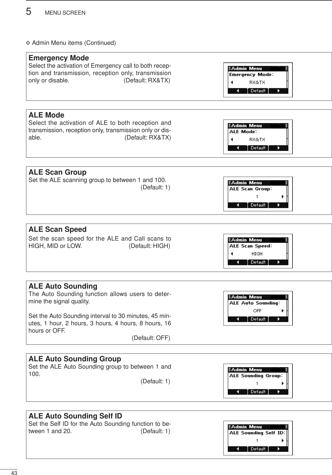
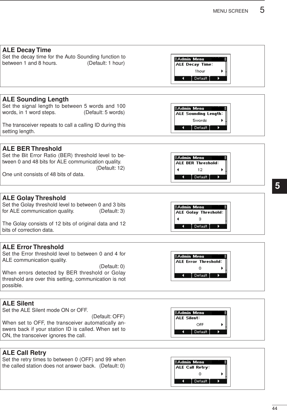
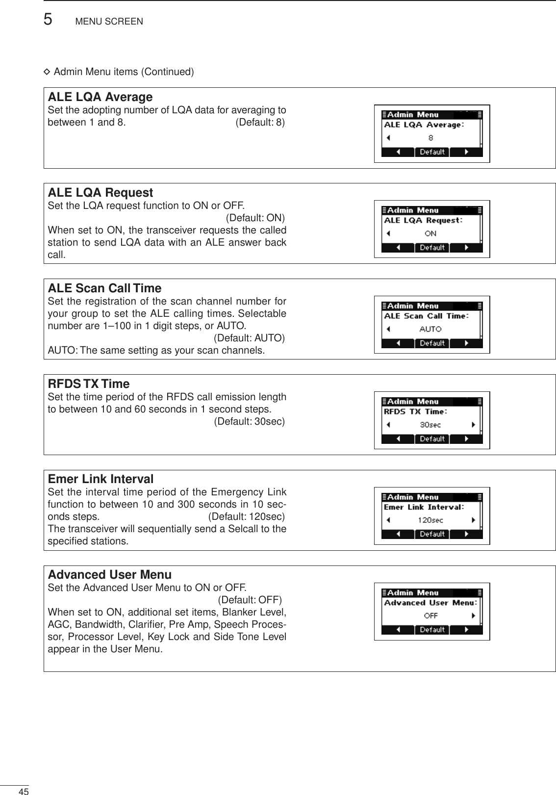
![385MENU SCREEN52001 NEW■ Admin MenuThe Admin Menu is used for programming infrequently changed values, settings or functions.D Entering the Administrator modeWhen first entering the Administrator mode, a login password may be required, depending on the prepro-gramming.q Turn OFF the transceiver power, if it is ON.w While holding down [], [ ] and [8], push [ ] to turn ON the transceiver power and enter the Ad-ministrator mode. • The “Login” display appears, depending on the prepro-gramming. e Push the keypad keys to enter your password, and then push [4] to enter the Administrator mode. • Repeatedly push [A/a](#) to select the character group, ABC (upper case letters), abc (lower case letters) or 123 (numbers). • Push [8] to delete a character. • Push [t](§) or [u](§§§) to move the cursor.[][]KeypadD Return to User modeq Turn OFF the transceiver power, if the transceiver is powered ON.w While holding down [HOME], push [ ] to turn ON the transceiver power to return to the User mode.D Entering Admin Menuq Hold down [MENU](HOME) for 1 second to enter the Menu screen.w Push [s] to select the Admin Menu, and then push [4].e Push [r] or [s] to select the desired item.r Push [t](§) or [u](§§§) to adjust or set the value or setting. • Hold down [Default](§§) for 1 second to set the default value or setting.t Push [MENU](HOME) twice to return to the normal operating screen.[Default] [][]/](https://usermanual.wiki/ICOM-orporated/329600/User-Guide-1729805-Page-43.png)
![2001 NEW465MENU SCREEN1234567891011121314151617Quick ReferenceCI-V BaudrateSet the data transfer rate to 300, 1200, 4800, 9600, 19200 bps or AUTO. (Default: AUTO)AF Line SelectWhen the optional AD-119 is connected, select the input for the modulation signals from an external unit, such as an HF email modem or TNC (Terminal Node Controller). (Default: USB)When MODEM is selected, the input for the modula-tion signals is from an internal or external modem.BIT DisplaySet the activation of Built-in Test display to ON or OFF. (Default: ON)When set to ON, the transceiver displays the device check screen after turning ON the power.CI-V AddressTo distinguish equipment, each CI-V transceiver has its own Icom standard address in hexadecimal code. The IC-F8100’s address is 82h. (Default: 82h)If you want to initialize the operating settings in the User Menu and Admin Menu without clearing mem-ory channel contents or ID contents, do the following steps.q Turn OFF the transceiver power, if the transceiver is powered ON.w While holding down [r] and [s], push [] to turn ON the transceiver power to reset the CPU./■ CPU Reset](https://usermanual.wiki/ICOM-orporated/329600/User-Guide-1729805-Page-51.png)
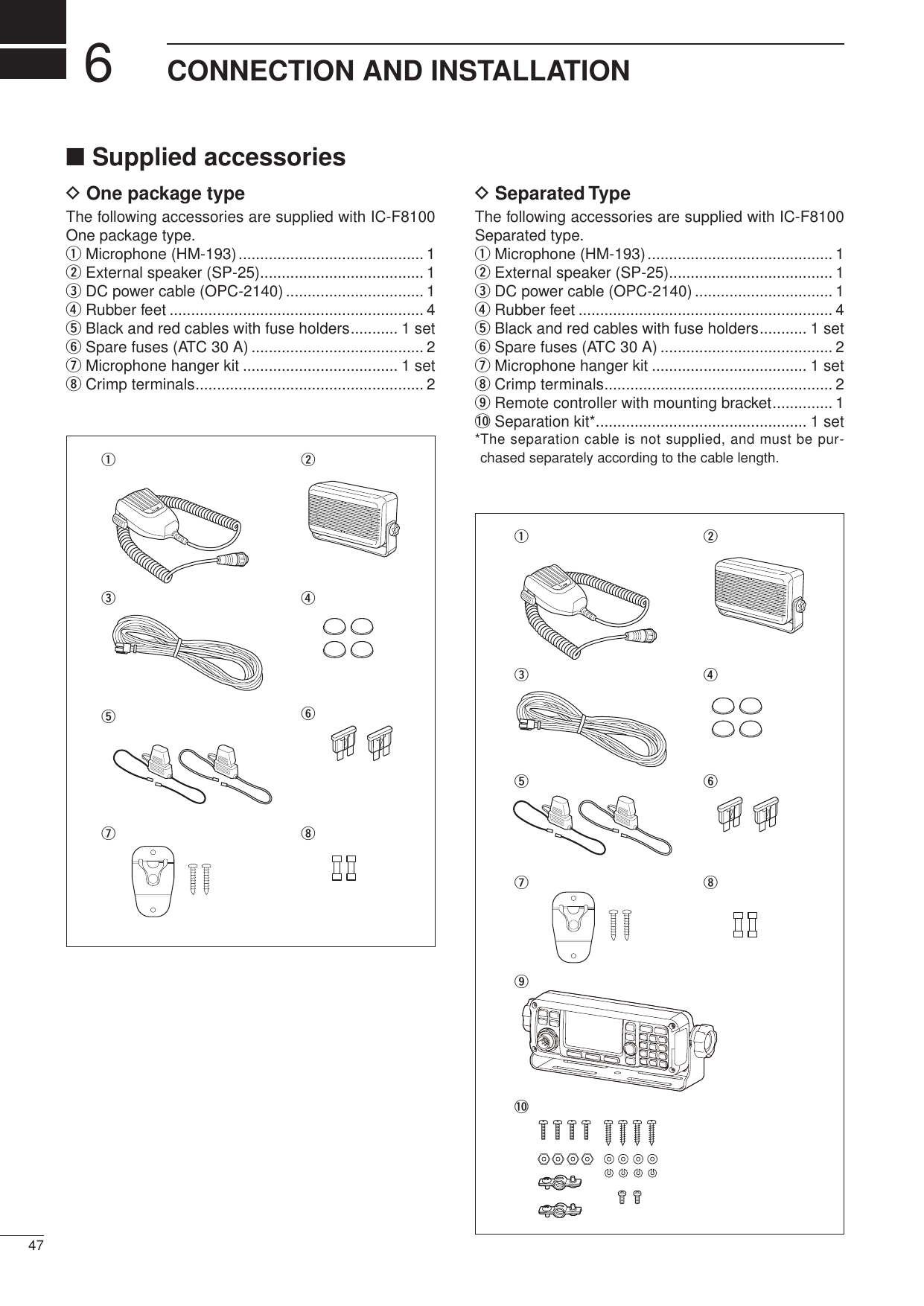
![496CONNECTION AND INSTALLATION2001 NEW 2001 NEW■ ConnectionsPCto[ACC1]to[ACC2]to [USB]to a USB portto a 13.8 V DC power sourceto [ACC1]to [ACC2]OPC-2126OPC-2127TransceiverUSB cable(purchase separately)AD-119SP-25+ red_ black12VBattery12VBatteryCrimpterminalR WARNING! NEVER remove the fuse holders from the black and red cables.Crimp R WARNING! NEVER connect to a 24 V battery. This will damage the transceiver.](https://usermanual.wiki/ICOM-orporated/329600/User-Guide-1729805-Page-54.png)
![2001 NEW506CONNECTION AND INSTALLATION1234567891011121314151617Quick ReferenceAT-140OPC-2205GroundIC-F8100 main unitto a 13.8 V DC power source to a GPS receiver to [ACC2]to [ACC1]OPC-2142 (10 m): 4 pinGround(see page 51)AT-140AT230Ground(see page 51)Ground(see page 51)IC-F8100 main unitOPC-2142 (10 m): 4 pinOPC-2143 (5 m)to a 13.8 V DC power source to[ACC2]to[ACC1]AD-119DO NOT stretch the Ground wire. This may cause a ground wire disconnection and/or damage. DO NOT pull the antenna and control cable re-ceptacles. This may cause a cable disconnection (in the tuner unit), inside connector damage or a bad connection. Wrap both the antenna and the control cable con-nectors with rubber vulcanizing tape, and then wrap electrical tape over the rubber vulcanizing tape to help in waterproofing. CAUTION: DO NOT transmit continuously while using an AT230, otherwise the AT230 will be dam-aged.](https://usermanual.wiki/ICOM-orporated/329600/User-Guide-1729805-Page-55.png)