ICOM orporated 332902 UHF Transceiver User Manual IC F3100D F4100D Series Instruction Manual
ICOM Incorporated UHF Transceiver IC F3100D F4100D Series Instruction Manual
UserManual.wiki
>
ICOM orporated
>
332902 User Manual
User Manual
Navigation menu
Upload a User Manual
Namespaces
Wiki Guide
HTML
PDF
Info
Views
User Manual
Discussion / Help
Navigation
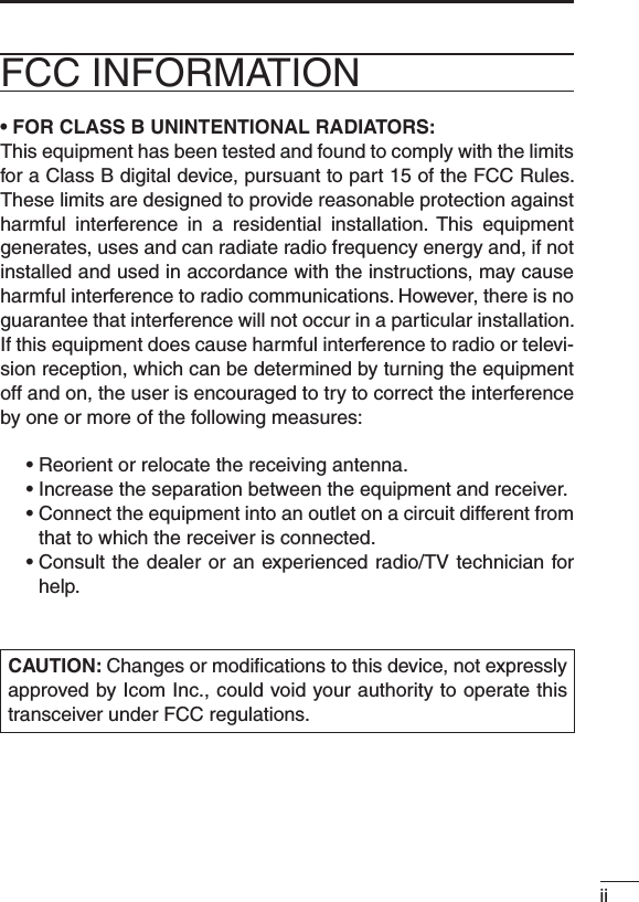
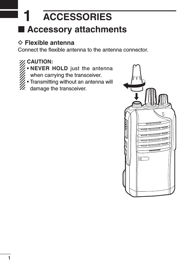
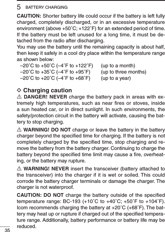
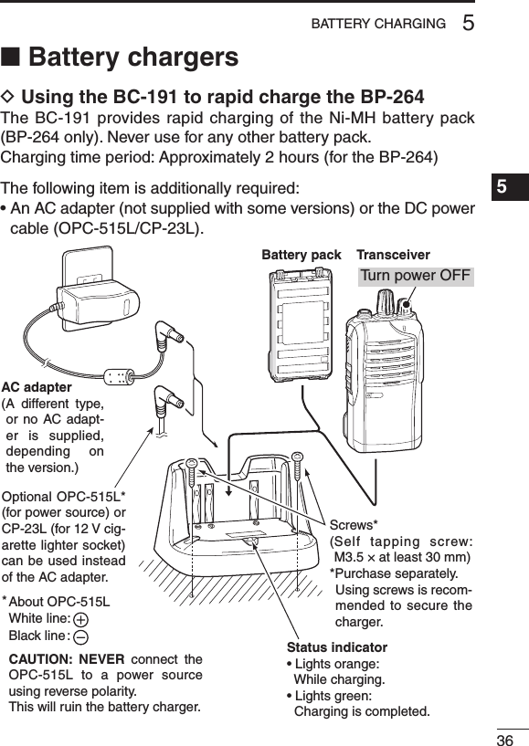
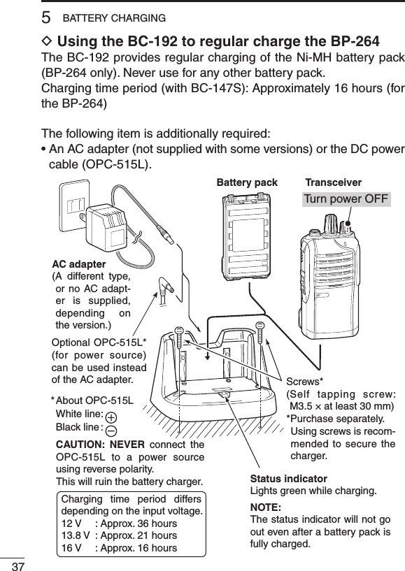
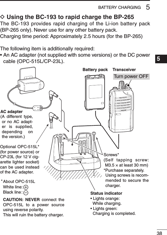
![iiiPRECAUTIONSR DANGER! NEVER short the terminals of the battery pack.R DANGER! Use and charge only specified Icom battery packs with Icom radios or Icom chargers. Only Icom battery packs are tested and approved for use with Icom radios or charged with Icom chargers. Using third-party or counterfeit battery packs or chargers may cause smoke, fire, or cause the battery to burst.R WARNING! NEVER hold the transceiver so that the antenna is very close to, or touching exposed parts of the body, especially the face or eyes, while transmitting. The transceiver will perform best if the microphone is 5 to 10 cm (2 to 4 inches) away from the lips and the transceiver is vertical.R WARNING! NEVER operate the transceiver with a headset or other audio accessories at high volume levels. Hearing experts advise against continuous high volume operation. If you experience a ringing in your ears, reduce the volume level or discontinue use.R WARNING! NEVER operate the transceiver while driving a vehicle. Safe driving requires your full attention—anything less may result in an accident.CAUTION: MAKE SURE the flexible antenna and battery pack are securely attached to the transceiver, and that the antenna and battery pack are dry before attachment. Exposing the inside of the transceiver to water will result in serious damage to the trans-ceiver.DO NOT operate the transceiver near unshielded electrical blast-ing caps or in an explosive atmosphere.DO NOT push [PTT] when not actually intending to transmit.DO NOT use or place the transceiver in direct sunlight or in areas with temperatures below –30°C (+22°F) or above +60°C (+140°F).](https://usermanual.wiki/ICOM-orporated/332902/User-Guide-1507198-Page-4.png)
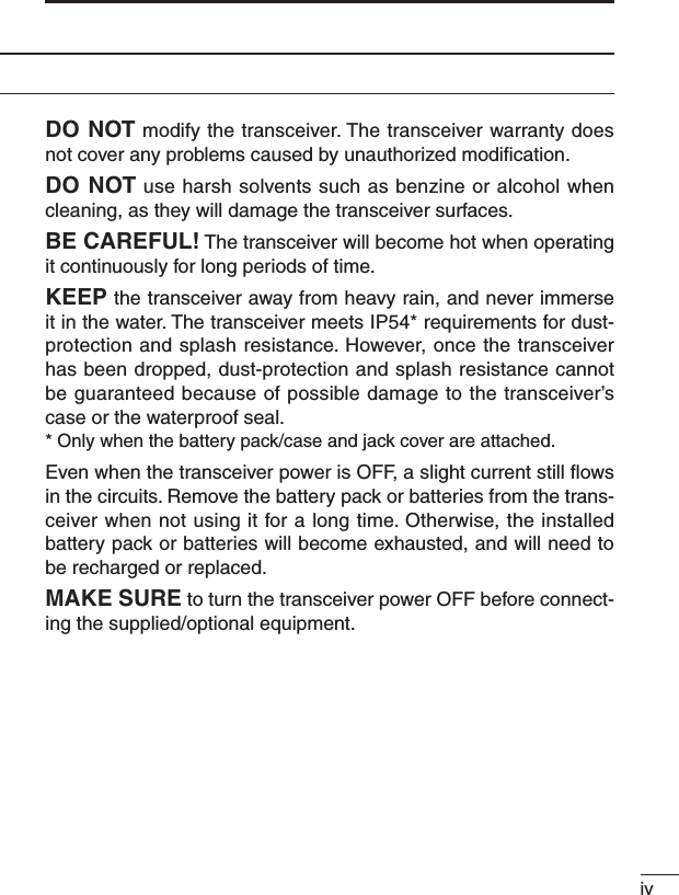
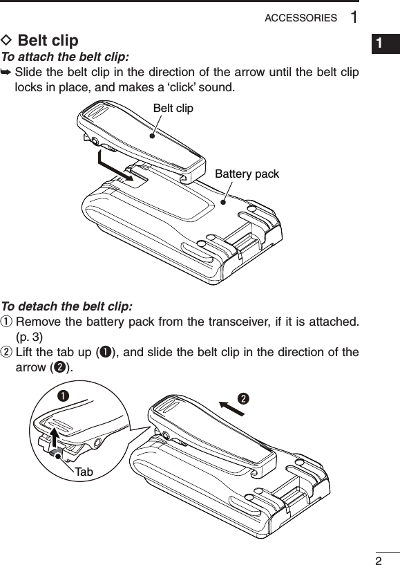
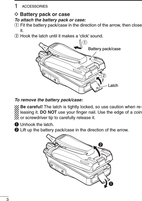
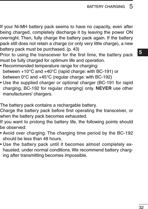
![41ACCESSORIES1234567891011121314151617181920NEVER remove or attach the battery pack/case when the trans-ceiver is wet or soiled. This may result in water or dust getting into the transceiver, battery pack/case, and may result in them being damaged.NOTE: Keep the battery terminals clean. It’s a good idea to clean the battery terminals once a week.D Jack coverAttach the jack cover when the optional equipment is not used.To attach the jack cover:q Attach the jack cover to the [SP MIC] jack.w Tighten the screws.To detach the jack cover:q Remove the screws with a phillips screwdriver.w Detach the jack cover to con-nect the optional equipment.wwwqqq](https://usermanual.wiki/ICOM-orporated/332902/User-Guide-1507198-Page-13.png)
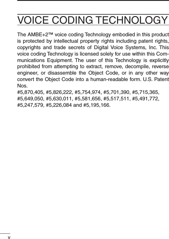
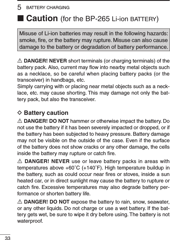
![52PANEL DESCRIPTION■ Front, top and side panelsMicrophoneSpeakerrweqyuitLOWER KEYUPPER KEYPTT SWITCHANTENNACONNECTORROTARYSELECTORLED INDICATORVOLUMECONTROLSPEAKER-MICROPHONEJACKq ROTARY SELECTOR Rotate to select the pre-programmed memory channels or scan lists, depending on the pre-programming.w VOLUME CONTROL [VOL] Rotate to turn the power ON or OFF, and adjust the audio level.](https://usermanual.wiki/ICOM-orporated/332902/User-Guide-1507198-Page-14.png)
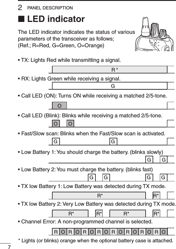
![62PANEL DESCRIPTIONe LED INDICATOR (p. 7)➥ Lights red* while transmitting. * When the optional battery case is attached, the LED indicator lights orange.➥ Lights green while receiving a signal, or when the squelch is open.➥ Lights/blinks orange when the matched 2/5-tone code is re-ceived, depending on the pre-programming.r SPEAKER-MICROPHONE JACK [SP MIC] Connect the optional speaker-microphone or VOX adapter cable.t LOWER KEY [Lower]y UPPER KEY [Upper] The desired function can be assigned by your dealer. (p. 8)u PTT SWITCH [PTT]Hold down to transmit; release to receive.i ANTENNA CONNECTOR Connect the antenna.1234567891011121314151617181920Jack coverNOTE: Attach the jack cover when the optional equipment is not used. (p. 4)](https://usermanual.wiki/ICOM-orporated/332902/User-Guide-1507198-Page-15.png)
![82PANEL DESCRIPTION■ Programmable function keysThe following functions can be assigned to the [Upper] and [Lower] programmable function keys.Consult your Icom dealer or system operator for details concerning your transceiver’s programming.SCANPush to start and cancel the scanning operation.•WhenthescanstartedwiththePowerONScanorAutoScanfunc-tion, push to pause the scanning operation. The paused scan re-sumes after the specified time period has passed.PRIORITY A CHANNEL, PRIORITY B CHANNELPush to select the Priority A or Priority B channel.PRIORITY A CHANNEL (REWRITE),PRIORITY B CHANNEL (REWRITE)➥ Push to select the Priority A or Priority B channel.➥ Hold down [Prio A (Rewrite)] or [Prio B (Rewrite)] for 1 second to assign the operating channel to Priority A or Priority B channel, respectively.MEMORY CHANNELS 1, 2, 3, 4Push to directly select memory channel 1, 2, 3 or 4, if programmed. Consult your dealer for details.LONE WORKER (p. 24)➥ Push to turn the Lone Worker function OFF.➥ Hold down to turn the Lone Worker function ON. •WhentheLoneWorkerfunctionisturnedON,andnooperationisperformed for the specified time period, the Emergency function is automatically turned ON.1234567891011121314151617181920](https://usermanual.wiki/ICOM-orporated/332902/User-Guide-1507198-Page-17.png)
![92PANEL DESCRIPTIONMONITOR, MONITOR (AUDIBLE)➥ Push to turn the CTCSS (DTCS) or 2/5-tone squelch Mute ON or OFF. •Only during LMR operation, push to open any squelch func-tions, or deactivate any mute functions. •Only during PMR operation, push to activate one or two of the following functions* on each channel. - Hold down to un-mute the channel (Audible mode). - Push to mute the channel (Inaudible mode). - Push to send a ‘reset code’ after the communication is finished. *Ask your dealer for details. NOTE: The un-mute condition may automatically return to the mute condition, after a specified time period.➥ Depending on the presetting, holding down this key for 1 sec-ond cancels a scan.LOCKHold down to electronically lock all programmable keys except [Moni(Audi)], [Call] (including Call A and Call B), [Emergency], Surveillance] and [Lone Worker].HIGH/LOW (p. 22)Select the transmit output power level temporarily or permanently, depending on the presetting.•Askyourdealerfortheoutputpowerlevelforeachselection.TALK AROUND➥ Push to turn the Talk Around function OFF.➥ Hold down to turn the Talk Around function ON. •TheTalkAroundfunctionequalizesthetransmitfrequencytothereceive frequency for transceiver-to-transceiver communication.DTMF AUTODIALPush to transmit a programmed DTMF code.](https://usermanual.wiki/ICOM-orporated/332902/User-Guide-1507198-Page-18.png)
![102PANEL DESCRIPTIONWIDE/NARROW➥ Push to switch the IF bandwidth to Wide. •Thewidepassbandwidthcanbeselectedfrom20or25kHzusingthe optional cloning software (PMR operation only). Ask your dealer for details.➥ Hold down to switch the IF bandwidth to Narrow.CALL, CALL A, CALL BPush to transmit a 2/5-tone code.•Tonecalltransmissionmaybenecessarybeforeyoucallanothersta-tion, depending on your signalling system.•[CallA]and/or[CallB]keysmaybeavailablewhenyoursystemem-ploys selective ‘Individual/Group’ calls. Ask your dealer which call is assigned to each key.EMERGENCYHold down for specified time period to transmit an emergency call.•Theemergencycalltransmitswithbeeps,and the LED lights red.•Thetransceivercan transmitan emergencycallwithout the beep sounding and the LED indicator lighting. Ask your dealer for details.•Ifyouwanttocanceltheemergencycall,holddownthekeyagainbefore transmitting the call.•Theemergencycallistransmittedonetimeonly,orrepeatedlyuntilre-ceiving an acknowledgement signal, or until the power is turned OFF. When a matched 5-tone code signal is received, the emergency func-When a matched 5-tone code signal is received, the emergency func-tion can be cancelled depending on the presetting. (PMR operation only)SURVEILLANCE➥ Push to turn the Surveillance function OFF.➥ Hold down to turn the Surveillance function ON. •WhenthisfunctionisturnedON,thebeepisnotheardandtheLEDdoes not light when a signal is received, or a key is pushed.1234567891011121314151617181920](https://usermanual.wiki/ICOM-orporated/332902/User-Guide-1507198-Page-19.png)
![SIRENHold down for 1 second to emit a siren sound.This function can be used for situations other than an emergency alert, such as a security alarm for example.The transceiver emits the siren sound until the power is turned OFF.ENCRYPTIONPush to turn the Voice Encryption function ON or OFF while operat-ing in the digital mode.ANNOUNCEPush to turn the Channel Announce function ON or OFF.•WhenthisfunctionisturnedON,thetransceiverannouncestheposi-tion of [ROTARY SELECTOR] between 1 and 16 when rotating [RO-TARY SELECTOR] to a desired scale.112PANEL DESCRIPTION](https://usermanual.wiki/ICOM-orporated/332902/User-Guide-1507198-Page-20.png)
![123BASIC OPERATION1234567891011121314151617181920■ Turning power ONPrior to using the transceiver for the first time, the battery pack must be fully charged for optimum life and operation. (p. 31)➥Rotate [VOL] to turn power ON.D Battery type selectionThe battery type must be selected according to the battery pack or case when it is changed, but only the first time it is used.Check the battery type before you begin the selection procedure.One to three beep(s) sound in sequence, so you must repeat the steps until the number of beeps matches your battery type.For example, if your battery type is a Li-ion battery pack, you must repeat the procedure until one beep is heard.q Set [ROTARY SELECTOR] to any channel other than Channel 16.w Rotate [VOL] to turn OFF the trans-ceiver’s power.e While holding down [PTT], rotate [VOL] to turn ON the power. •Youshouldhold[PTT]untilthebeepsounds. (It takes approximately 5 second.) •One beep sounds when the Li-ionbattery is selected. •Twobeepssoundwhenthebatterycaseisselected. •ThreebeepssoundwhentheNi-MHbatteryisselected.r After the beep sounds, release [PTT].t Repeat steps w to r until you select the attached battery type.NOTE: This operation may not be available, depending on the presetting. Ask your dealer for details.[VOL][VOL][PTT][ROTARY SELECTOR]](https://usermanual.wiki/ICOM-orporated/332902/User-Guide-1507198-Page-21.png)
![■ Channel selectionSeveral types of channel selecting methods are available. They may differ, according to your system set up.To select a desired operating channel, do one of the following.•Rotate[ROTARYSELECTOR].•Pushoneofmemorychannelkeys,[MR-CH1]to[MR-CH4].•Pushoneofthesekeys,[PrioA],[PrioB],[PrioA(Rewrite)]and[Prio B (Rewrite)].AUTOMATIC SCAN TYPE:Selecting a channel is not necessary for this type. When turning ON the power, the transceiver automatically starts scanning. Scanning stops when a call is received.NOTE: If the Move to Priority A channel at Power ON function (p. 22) is turned ON, the transceiver does not start scanning at power ON.133BASIC OPERATION](https://usermanual.wiki/ICOM-orporated/332902/User-Guide-1507198-Page-22.png)
![143BASIC OPERATION1234567891011121314151617181920■ Call procedureWhen your system employs tone signalling (excluding CTCSS and DTCS), the tone call procedure may be necessary prior to voice transmission. The tone signalling that is employed in the transceiver may be a selective calling system, which allows you to call only specific station(s), and prevent unwanted stations from contacting you.q Select a desired TX code channel or 2/5-tone code, according to your System Operator’s instructions. •Thismaynotbenecessary,dependingonprogramming.w Push [Call] (assigned to one of the dealer programmable keys.) (p. 10)e After transmitting a 2/5-tone code, the remainder of your com-munication can be carried out normally.Selective calling Non-selective calling](https://usermanual.wiki/ICOM-orporated/332902/User-Guide-1507198-Page-23.png)
![153BASIC OPERATION■ Receiving and transmittingCAUTION: Transmitting without an antenna will damage the transceiver. See page 1 for antenna attachment.Receiving:q Rotate [VOL] to turn ON the power.w Rotate [ROTARY SELECTOR], or push one of the memory chan-nel keys, [MR-CH 1] to [MR-CH 4], to select a channel.e When receiving a call, adjust the audio output to a comfortable listening level.NOTE: When a matched RX code signal is received, audio from the microphone is automatically transmitted for a specified time period.** Depending on the presetting. Ask your dealer for details.Transmitting:Wait for the channel to become clear to avoid interference.q While holding down [PTT], speak into the microphone at a nor-mal voice level.w Release [PTT] to return to receive.IMPORTANT: To maximize the readability of your signal;1. Pause briefly after pushing [PTT].2. Hold the microphone 5 to 10 cm (2 to 4 inches) from your mouth, then speak into the microphone at a normal voice level.](https://usermanual.wiki/ICOM-orporated/332902/User-Guide-1507198-Page-24.png)
![163BASIC OPERATION1234567891011121314151617181920D Transmitting notes• Transmit inhibit functionThe transceiver has several inhibit functions, which restrict trans-mission under the following conditions:- The channel is muted. (PMR operation only)- The channel is busy.- A signal with the un-matched (or matched) CTCSS (or DTCS) tone is received.- The selected channel is a ‘receive only’ channel.• Time-out timerAfter continuously transmitting longer than the pre-programmed time period, the time-out timer activates, and stops further transmitting.• Penalty timerOnce the time-out timer activates, transmitting is further inhibited for a time period determined by the penalty timer.• PTTID callThe transceiver automatically sends the ID code (5-tone, DTMF, BIIS, MDC system or IDAS operations) when [PTT] is pushed (be-ginning of the transmission) and/or released (end of transmission), depending on the presetting.](https://usermanual.wiki/ICOM-orporated/332902/User-Guide-1507198-Page-25.png)
![D DTMF transmissionIf the transceiver has [DTMF Autodial] assigned to it, the automatic DTMF transmission function is usable.➥ Push [DTMF Autodial] to transmit the DTMF code.D Receiving a Stun, Kill and Revive commandThe dispatcher can send a 2/5-tone signal that will stun, kill or re-vive your transceiver.When the Stun command is received, a beep sounds*, and the transceiver becomes unusable. Receiving a Revive command is necessary to operate the transceiver again in this case.When the Kill command is received, a beep sounds*, and the trans-ceiver becomes unusable (the transceiver switches to the cloning required condition). Cloning the transceiver is necessary to operate the transceiver again in this case.* Depending on the presetting. Ask your dealer for details.173BASIC OPERATION](https://usermanual.wiki/ICOM-orporated/332902/User-Guide-1507198-Page-26.png)
![■ Setting the microphone gainAdjusts the microphone gain.q Rotate [VOL] to turn the trans-ceiver power OFF.w Set [ROTARY SELECTOR] to Channel 16.e While holding down [Upper], ro-tate [VOL] to turn ON the power and enter the microphone gain adjustment mode.r Push [Upper] to increase, or push [Lower] to decrease the microphone gain. •Theadjustablerangeis1(mini-mum) to 4 (maximum). •A beep sounds after pushing[Upper] or [Lower]. An error beep sounds if you try to decrease more than 1 or try to increase more than 4. Therefore, you can determine the current level setting by the type of beep that sounds.t Rotate [VOL] to turn the power OFF, then ON again to exit the microphone gain adjustment mode.NOTE:•Thisoperationmaynotbeavailable,dependingonthepreset-ting. Ask your dealer for details.•WhenusingtheVOXfunction,werecommendsettingthemi-crophone gain to 3. However, you can adjust it to suit your op-erating environment (including your headset performance).183BASIC OPERATION1234567891011121314151617181920[Upper][VOL][ROTARY SELECTOR]](https://usermanual.wiki/ICOM-orporated/332902/User-Guide-1507198-Page-27.png)
![■ Setting the squelch levelThe squelch circuit mutes the received audio signal, depending on the signal strength.q Rotate [VOL] to turn the trans-ceiver power OFF.w Set [ROTARY SELECTOR] to any channel other than Chan-nel 16.e While holding down [Upper], ro-tate [VOL] to turn ON the power and enter the squelch level ad-justment mode.r Push [Upper] to increase the squelch level (tight squelch), or push [Lower] to decrease the squelch level (loose squelch). •Theadjustablerangeis0(loosesquelch) to 9 (tight squelch). •A beep sounds after pushing[Upper] or [Lower]. An error beep sounds if you try to decrease more than 0 or try to increase more than 9. Therefore, you can determine the current level setting by the type of beep that sounds.t Rotate [VOL] to turn the power OFF, then ON again to exit the squelch level adjustment mode.NOTE: This operation may not be available, depending on the presetting. Ask your dealer for details.193BASIC OPERATION[VOL][Upper][ROTARY SELECTOR]](https://usermanual.wiki/ICOM-orporated/332902/User-Guide-1507198-Page-28.png)
![■ Setting the Beep levelThe beep function can be turned ON or OFF, and its level can be adjusted between 1 and 5, or 1 (linked) and 5 (linked). When a Linked option is selected, the beep level is adjustable with [VOL].q Rotate [VOL] to turn the trans-ceiver power OFF.w Set [ROTARY SELECTOR] to any channel other than Chan-nel 16.e While holding down [Lower], ro-tate [VOL] to turn ON the power and enter the beep level adjust-ment mode.r Push [Upper] to change the beep level, or push [Lower] to turn the beep function ON or OFF. •Theadjustablerangeis1to5or1 (Linked) to 5 (Linked). •Ifthelevelisseton1to4or1(Linked) to 4 (Linked), pushing [Upper] increases the level. If the level is 5 or 5 (Linked), 1 (Linked) or 1 is selected after push-ing [Upper], respectively. •A beep sounds after pushing [Upper].Therefore, you can deter-mine the current level setting by the type of beep that sounds. •OnebeepsoundswhenthebeepfunctionisturnedONafterpush-ing [Lower].t Rotate [VOL] to turn the power OFF, then ON again to exit the beep level adjustment mode.NOTE: This operation may not be available, depending on the presetting. Ask your dealer for details.203BASIC OPERATION1234567891011121314151617181920[VOL][Lower][ROTARY SELECTOR]](https://usermanual.wiki/ICOM-orporated/332902/User-Guide-1507198-Page-29.png)
![213BASIC OPERATION■ Setting the Ringer levelThe Ringer level can be adjusted between 1 and 5, or 1 (Linked) and 5 (Linked). When a Linked option is selected, the Ringer level is adjustable with [VOL].q Rotate [VOL] to turn the trans-ceiver power OFF.w Set [ROTARY SELECTOR] to Channel 16.e While holding down [Lower], ro-tate [VOL] to turn ON the power and enter the Ringer level ad-justment mode.r Push [Upper] to increase, or push [Lower] to decrease the Ringer level. •Theadjustablerangeis1to5or1 (Linked) to 5 (Linked). •If the level is set on 5 or 5(Linked), pushing [Upper] selects 1 (Linked) or 1, respectively. If the level is 1 or 1 (Linked), pushing [Lower] selects 5 (Linked) or 5, respectively. •A beep sounds after pushing [Upper] or [Lower]. Therefore, youcan determine the current level setting by the type of beep that sounds.t Rotate [VOL] to turn the power OFF, then ON again to exit the beep level adjustment mode.NOTE: This operation may not be available, depending on the presetting. Ask your dealer for details.[VOL][Lower][ROTARY SELECTOR]](https://usermanual.wiki/ICOM-orporated/332902/User-Guide-1507198-Page-30.png)
![223BASIC OPERATION1234567891011121314151617181920■ Output power level selectionIf the transceiver has [High/Low] assigned to it, the transmit output power level can be selected, depending on the presetting.When the battery case is selected as the battery type, or the bat-tery voltage drops to a low power level and the LED indicator sta-tus is “Low Battery 2,” the output power automatically switches to “Low 1.” (pp. 7, 12)➥ Push [High/Low] to select the transmit output power level. •Onebeepsoundswhen“Low1”isselected. •Twobeepssoundwhen“Low2”isselected. •Threebeepssoundwhen“High”isselected.■ Priority A channel selectionWhen one of the following operations is performed, the transceiver automatically selects the Priority A channel.•TurningthepowerON The Priority A channel is selected each time the transceiver pow-er is turned ON.•AutoresetThe Priority A channel is selected when the Auto Reset timer ends.](https://usermanual.wiki/ICOM-orporated/332902/User-Guide-1507198-Page-31.png)
![233BASIC OPERATION■ MDC 1200 system operationThe MDC 1200 signaling system enhances your transceiver’s capa-bilities. It allows PTT ID* and Emergency signaling.* When [PTT] is pushed and/or released, the transceiver transmits your station ID.D Transmitting an Emergency CallThe MDC 1200 system’s Emergency feature can be accessed using the [Emergency] key. The transceiver will send an Emergency MDC 1200 system command once, or repeatedly for a programmed number of times until it receives an acknowledgement signal.The emergency call can be transmitted without a beep sound, de-pending on how the emergency function is programmed. Ask your dealer for details.■ Lone Worker Emergency CallWhen the Lone Worker function is turned ON, and no operation is performed for the specified time period*, the transceiver enters the emergency mode, and then the countdown for the emergency call transmission starts.After the specified time period* has passed, an emergency call is automatically transmitted once, or repeatedly*.If someone operates the transceiver before the call is transmitted, the transceiver exits the emergency mode, and the emergency call is can-celled.* Depending on the presetting. Ask your dealer for details.q Hold down [Lone Worker] to turn ON the Lone Worker function.w Push [Lone Worker] to turn OFF the Lone Worker function.](https://usermanual.wiki/ICOM-orporated/332902/User-Guide-1507198-Page-32.png)
![243BASIC OPERATION1234567891011121314151617181920■ Emergency CallWhen [Emergency] is held down for the specified time period*, the emergency signal is transmitted once, or repeatedly, on the speci-fied emergency channel.A repeat emergency signal is automatically transmitted until you turn the power OFF. Depending on the pre-programmed settings, receiving a matching 5-tone code cancels the transmission. When no emergency channel is specified, the signal is transmitted on the previously selected channel.If you want to cancel the emergency call, hold down [Emergency] again before transmitting the call.If your transceiver is programmed for Silent operation, you can transmit an Emergency call without the beep sounding and the LED indicator lighting.IMPORTANT: It is recommended to set an emergency channel individually to provide the certain emergency call operation.D NOTESDepending on the presetting, the following functions are automati-cally activated. Ask your dealer for details.• Auto TX functionAfter the emergency call transmission, audio from the microphone is automatically transmitted for a specified time period.*• Auto RX functionAfter the emergency call transmission, the transceiver stands by in the audible mode for the specified time period.** Depending on the presetting. Ask your dealer for details.](https://usermanual.wiki/ICOM-orporated/332902/User-Guide-1507198-Page-33.png)
![254IDAS OPERATION■ IDAS operationThe IC-F3100D series and IC-F4100D series provide Icom Digital Advanced System (IDAS) that meets the 6.25 kHz emission mask requirements for narrow banding, and increases efficiency of chan-nel allocation and use of spectrum.NOTE: During IDAS operation, BIIS 1200 and MDC 1200 sys-tem operations are not available.■ IDAS-Trunk operationThe IDAS-Trunk system enables further effective channel manage-ment by sharing a minimum of channels with a large number of users.Rotate [ROTARY SELECTOR] to select the memory channel that is programmed in the IDAS-Trunk zone.NOTE: During IDAS-Trunk operation, you can receive and trans-mit digital calls in the same way with the following IDAS opera-tion.](https://usermanual.wiki/ICOM-orporated/332902/User-Guide-1507198-Page-34.png)
![264IDAS OPERATION1234567891011121314151617181920■ Receiving a callD Receiving a Call Alertq When a Call Alert is received; •Thetransceiverwillautomaticallytransmittheacknowledgement. •TheLEDindicatorblinksorange. •Beepssound.w Hold down [PTT], then speak into the microphone.e Release [PTT] to receive a response.NOTE: The LED indicator or Beeps may differ, depending on the presetting. Ask your dealer for details.D Receiving a Stun, Kill or ReviveIf an individual call with Stun or Kill command is received (RAN code matching is not necessary depending on the presetting), the transceiver will automatically transmit the acknowledgement, and then you cannot receive* or transmit.* Depending on the received Stun command setting.➥ When a Stun command is received; •ThetransceivercannotbeoperateduntiltheindividualcallwithRevive command is received (RAN code matching is not nec-essary depending on the presetting) or until the data cloning is performed. •Evenif[ROTARYSELECTOR]ischanged,thetransceiverwillkeep the same channel as the Stun command is received.➥ When a Kill command is received; •TheLEDindicatoralternatelyblinksredandgreen. •The transceiver cannot be operated until the data cloning isperformed. Ask your dealer for details.NOTE: Depending on the presetting, the transceiver ignores the Stun, Revive and Kill commands, which are from a non-specified station.](https://usermanual.wiki/ICOM-orporated/332902/User-Guide-1507198-Page-35.png)
![284IDAS OPERATION1234567891011121314151617181920■ Transmitting a callIDAS operation allows you to make a call to a specific station (In-dividual call) or to a particular group (Talkgroup call). Other digital mode transceivers on the channel will not receive a call that does not match their individual or talkgroup ID and/or RAN (Radio Ac-cess Number) code.D Transmitting an Emergency CallWhen [Emergency] is held down for the specified time period, the emergency signal (digital command) is transmitted once or repeat-edly* on the specified emergency channel. When no emergency chan-nel is specified, the signal is transmitted on the operating channel.* When the Repeat Cancel function is ON, the transceiver cancels repeating after receiving an acknowledgement.When the Repeat Cancel function is OFF, the transceiver repeats calling according to the number of repeat cycles, even after re-ceiving an acknowledgement.Individual or Talkgroup call types of emergency calls can be pre-fixed. If the call type is not pre-fixed, the default or selected call type is used.If you want to cancel the emergency call, hold down [Emergency] again before transmitting the call.If your transceiver is programmed for Silent operation, you can transmit an Emergency call without the beep sounding and the LED indicator lighting.The transceiver can also be programmed to keep the microphone open during an emergency call, allowing monitoring of the situation.Ask your dealer for details.](https://usermanual.wiki/ICOM-orporated/332902/User-Guide-1507198-Page-37.png)
![304IDAS OPERATION1234567891011121314151617181920■ Position data transmissionWhen an optional HM-171GP or any other GPS receiver is con-nected to the transceiver, the position (longitude and latitude) data can be transmitted automatically when; •AftersendingaStatusCall - Set the ‘Send with Status Call’ item as ‘Enable.’ •AftersendinganEmergencyCall - Set the ‘Send with Emergency’ item as ‘Enable.’ •AftersendingaVoiceCall - Set the ‘Send with Voice Call’ item as ‘Enable.’Ask your dealer or system operator for connection details.■ Status message transmissionThe status message can be transmitted automatically.The status message is transmitted when the transceiver is turned ON or OFF. - Select a status message to be transmitted in ‘Power ON Status’ or ‘Power OFF Status’ item, respectively. - Select a target station ID in ‘Power Status ID’.■ Encryption functionThe encryption function enables voice scrambling, which provides private digital communication between stations.Push [Encryption] to turn the encryption function ON or OFF.](https://usermanual.wiki/ICOM-orporated/332902/User-Guide-1507198-Page-39.png)
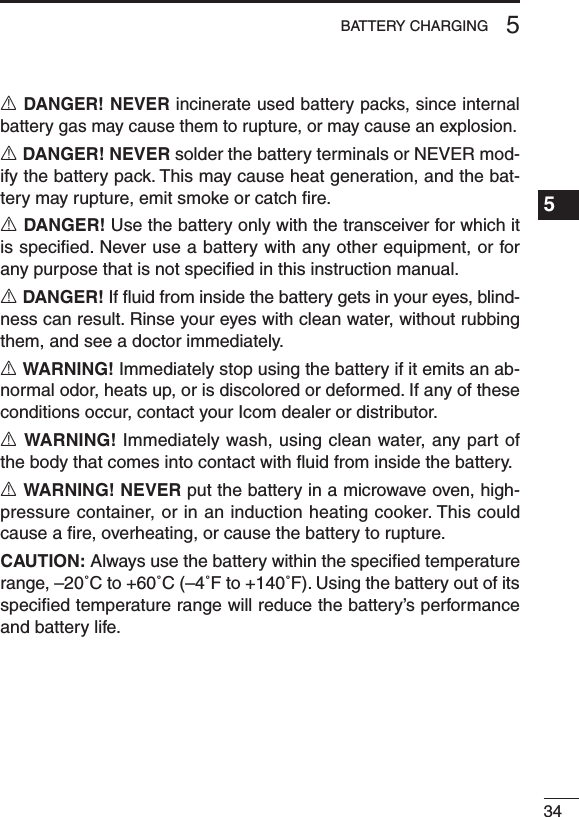
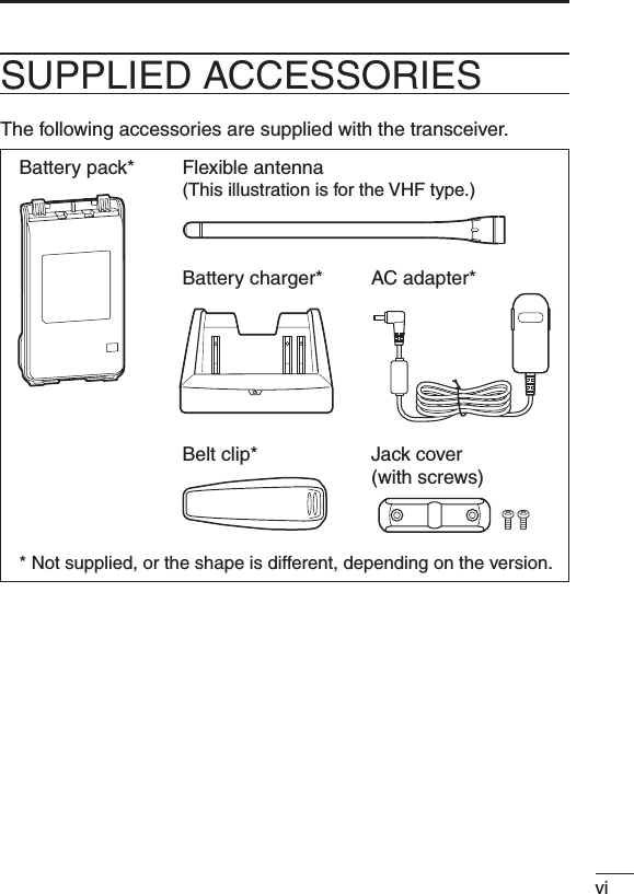
![467OPTIONS1234567891011121314151617181920■ VOX functionThe transceiver has a VOX function, which allows you hands-free operation.An optional headset (HS-94/HS-95/HS-97) and a plug adapter cable (OPC-2004) are additionally required for operation.•The VOX (voice operated transmission) function starts transmittingwhen you speak into the microphone, without needing to push the PTT switch; then, automatically returns to receive when you stop speak-ing.D Optional unit connectionq Rotate [VOL] to turn the transceiver power OFF.w Remove the jack cover. (p. 4)e Connect the optional headset (HS-94, HS-95 or HS-97) and OPC-2004 as described below.HS-94OPC-2004qwe[VOL]](https://usermanual.wiki/ICOM-orporated/332902/User-Guide-1507198-Page-55.png)
![477OPTIONSD Turning the VOX function ON or OFFThe VOX function can be turned ON or OFF when turning the trans-ceiver power ON.q Rotate [VOL] to turn the trans-ceiver power OFF.w Set [ROTARY SELECTOR] to any channel other than Chan-nel 16.e While holding down [PTT] and [Upper], rotate [VOL] to turn ON the power to switch the VOX function ON or OFF. •OnebeepsoundswhentheVOXfunction is turned OFF. •TwobeepssoundwhentheVOXfunction is turned ON.NOTE: This operation may not be available, depending on the presetting. Ask your dealer for details.[VOL][Upper][PTT][ROTARY SELECTOR]](https://usermanual.wiki/ICOM-orporated/332902/User-Guide-1507198-Page-56.png)
![487OPTIONS1234567891011121314151617181920D Setting the VOX gainThe VOX sensitivity level can be adjusted from 1 (minimum) to 10 (maximum).q Connect the optional headset (HS-94, HS-95 or HS-97) and OPC-2004. (p. 46)w Rotate [VOL] to turn the trans-ceiver power OFF.e Set [ROTARY SELECTOR] to Channel 16.r While holding down [PTT] and [Upper], rotate [VOL] to turn ON the power and enter the VOX gain adjustment mode.t Push [Upper] to increase, or push [Lower] to decrease the VOX gain while speaking into the optional headset. •Theadjustablerangeis1(mini-mum) to 10 (maximum). •Abeepsoundsafterpushing[Upper]or[Lower]. If the level is set on 1 or 10, an error beep sounds after pushing. Therefore, you can determine the current level setting by the type of beep that sounds.y Rotate [VOL] to turn the power OFF, then ON to exit the VOX gain adjustment mode.NOTE:•Thisoperationmaynotbeavailable,dependingonthepreset-ting. Ask your dealer for details.•Set the microphone gain before setting the VOX gain. (p. 18)[VOL][Upper][PTT][ROTARY SELECTOR]](https://usermanual.wiki/ICOM-orporated/332902/User-Guide-1507198-Page-57.png)