ICOM orporated 332902 UHF Transceiver User Manual IC F3100D F4100D Series Instruction Manual
ICOM Incorporated UHF Transceiver IC F3100D F4100D Series Instruction Manual
User Manual

INSTRUCTION MANUAL
This device complies with Part 15 of the FCC
Rules. Operation is subject to the condition that
this device does not cause harmful interference.
UHF TRANSCEIVERS
iF4100D
Series
VHF TRANSCEIVERS
iF3100D
Series
Limited functions only
Limited functions only

i
FOREWORD
READ ALL INSTRUCTIONS carefully and completely before
using the transceiver.
SAVE THIS INSTRUCTION MANUAL— This instruc-
tion manual contains important operating instructions for the IC-
F3101D/IC-F3103D/IC-F3106D VHF TRANSCEIVERS and the
IC-F4101D/IC-F4103D/IC-F4106D UHF TRANSCEIVERS.
EXPLICIT DEFINITIONS
WORD DEFINITION
RDANGER! Personal death, serious injury or an explo-
sion may occur.
RWARNING! Personal injury, fire hazard or electric shock
may occur.
CAUTION Equipment damage may occur.
NOTE
If disregarded, inconvenience only. No risk
of personal injury, fire or electric shock.
Icom, Icom Inc. and the Icom logo are registered trademarks of Icom Incorpo-
rated (Japan) in Japan, the United States, the United Kingdom, Germany, France,
Spain, Russia and/or other countries.

ii
FCC INFORMATION
• FOR CLASS B UNINTENTIONAL RADIATORS:
This equipment has been tested and found to comply with the limits
for a Class B digital device, pursuant to part 15 of the FCC Rules.
These limits are designed to provide reasonable protection against
harmful interference in a residential installation. This equipment
generates, uses and can radiate radio frequency energy and, if not
installed and used in accordance with the instructions, may cause
harmful interference to radio communications. However, there is no
guarantee that interference will not occur in a particular installation.
If this equipment does cause harmful interference to radio or televi-
sion reception, which can be determined by turning the equipment
off and on, the user is encouraged to try to correct the interference
by one or more of the following measures:
•Reorientorrelocatethereceivingantenna.
•Increasetheseparationbetweentheequipmentandreceiver.
•Connecttheequipmentintoanoutletonacircuitdifferentfrom
that to which the receiver is connected.
•Consultthedealeroranexperiencedradio/TVtechnicianfor
help.
CAUTION: Changes or modifications to this device, not expressly
approved by Icom Inc., could void your authority to operate this
transceiver under FCC regulations.

iii
PRECAUTIONS
R DANGER! NEVER short the terminals of the battery pack.
R DANGER! Use and charge only specified Icom battery packs
with Icom radios or Icom chargers. Only Icom battery packs are
tested and approved for use with Icom radios or charged with Icom
chargers. Using third-party or counterfeit battery packs or chargers
may cause smoke, fire, or cause the battery to burst.
R WARNING! NEVER hold the transceiver so that the antenna
is very close to, or touching exposed parts of the body, especially
the face or eyes, while transmitting. The transceiver will perform
best if the microphone is 5 to 10 cm (2 to 4 inches) away from the
lips and the transceiver is vertical.
R WARNING! NEVER operate the transceiver with a headset
or other audio accessories at high volume levels. Hearing experts
advise against continuous high volume operation. If you experience
a ringing in your ears, reduce the volume level or discontinue use.
R WARNING! NEVER operate the transceiver while driving a
vehicle. Safe driving requires your full attention—anything less may
result in an accident.
CAUTION: MAKE SURE the flexible antenna and battery pack
are securely attached to the transceiver, and that the antenna and
battery pack are dry before attachment. Exposing the inside of
the transceiver to water will result in serious damage to the trans-
ceiver.
DO NOT operate the transceiver near unshielded electrical blast-
ing caps or in an explosive atmosphere.
DO NOT push [PTT] when not actually intending to transmit.
DO NOT use or place the transceiver in direct sunlight or in areas
with temperatures below –30°C (+22°F) or above +60°C (+140°F).

iv
PRECAUTIONS
DO NOT modify the transceiver. The transceiver warranty does
not cover any problems caused by unauthorized modification.
DO NOT use harsh solvents such as benzine or alcohol when
cleaning, as they will damage the transceiver surfaces.
BE CAREFUL! The transceiver will become hot when operating
it continuously for long periods of time.
KEEP the transceiver away from heavy rain, and never immerse
it in the water. The transceiver meets IP54* requirements for dust-
protection and splash resistance. However, once the transceiver
has been dropped, dust-protection and splash resistance cannot
be guaranteed because of possible damage to the transceiver’s
case or the waterproof seal.
* Only when the battery pack/case and jack cover are attached.
Even when the transceiver power is OFF, a slight current still flows
in the circuits. Remove the battery pack or batteries from the trans-
ceiver when not using it for a long time. Otherwise, the installed
battery pack or batteries will become exhausted, and will need to
be recharged or replaced.
MAKE SURE to turn the transceiver power OFF before connect-
ing the supplied/optional equipment.

v
VOICE CODING TECHNOLOGY
The AMBE+2™ voice coding Technology embodied in this product
is protected by intellectual property rights including patent rights,
copyrights and trade secrets of Digital Voice Systems, Inc. This
voice coding Technology is licensed solely for use within this Com-
munications Equipment. The user of this Technology is explicitly
prohibited from attempting to extract, remove, decompile, reverse
engineer, or disassemble the Object Code, or in any other way
convert the Object Code into a human-readable form. U.S. Patent
Nos.
#5,870,405, #5,826,222, #5,754,974, #5,701,390, #5,715,365,
#5,649,050, #5,630,011, #5,581,656, #5,517,511, #5,491,772,
#5,247,579, #5,226,084 and #5,195,166.
vi
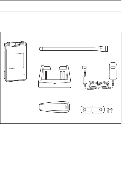
SUPPLIED ACCESSORIES
The following accessories are supplied with the transceiver.
Flexible antenna
(This illustration is for the VHF type.)
Battery pack*
Belt clip* Jack cover
(with screws)
Battery charger*AC adapter*
* Not supplied, or the shape is different, depending on the version.

vii
TABLE OF CONTENTS
FOREWORD ........................................................................................ i
EXPLICIT DEFINITIONS ...................................................................... i
FCC INFORMATION ........................................................................... ii
PRECAUTIONS .............................................................................. iii, iv
VOICE CODING TECHNOLOGY ........................................................ v
SUPPLIED ACCESSORIES ............................................................... vi
TABLE OF CONTENTS ................................................................ vii, vii
1 ACCESSORIES ......................................................................... 1–4
■ Accessory attachments .............................................................. 1
2 PANEL DESCRIPTION ............................................................ 5–11
■ Front, top and side panels .......................................................... 5
■ LED indicator .............................................................................. 7
■ Programmable function keys ......................................................8
3 BASIC OPERATION .............................................................. 12–24
■ Turning power ON ..................................................................... 12
■ Channel selection ..................................................................... 13
■ Call procedure .......................................................................... 14
■ Receiving and transmitting ....................................................... 15
■ Setting the microphone gain ..................................................... 18
■ Setting the squelch level ...........................................................19
■ Setting the Beep level ............................................................... 20
■ Setting the Ringer level ............................................................. 21
■ Output power level selection ..................................................... 22
■ Priority A channel selection ...................................................... 22
■ MDC 1200 system operation .................................................... 23
■ Lone Worker Emergency Call ................................................... 23
■ Emergency Call ........................................................................ 24
4 IDAS OPERATION ................................................................. 25–30
■ IDAS operation ......................................................................... 25
■ IDAS-Trunk operation ...............................................................25
■ Receiving a call......................................................................... 26

viii
1
2
3
4
5
6
7
8
9
10
11
12
13
14
15
16
17
18
19
20
■ Transmitting a call ..................................................................... 28
■ Position data transmission ........................................................30
■ Status message transmission ................................................... 30
■ Encryption function ................................................................... 30
5 BATTERY CHARGING .......................................................... 31–41
■ Caution (for the BP-264 ni-m h b at t e r y ) .................................... 31
■ Caution (for the BP-265 Li-ion b at t e r y ) ....................................33
■ Battery chargers ....................................................................... 36
6 BATTERY CASE .......................................................................... 42
■ Optional battery case (BP-263) ................................................ 42
7 OPTIONS ............................................................................... 43–48
■ VOX function ............................................................................. 46
8 SAFETY TRAINING INFORMATION ..................................... 49–50
TABLE OF CONTENTS
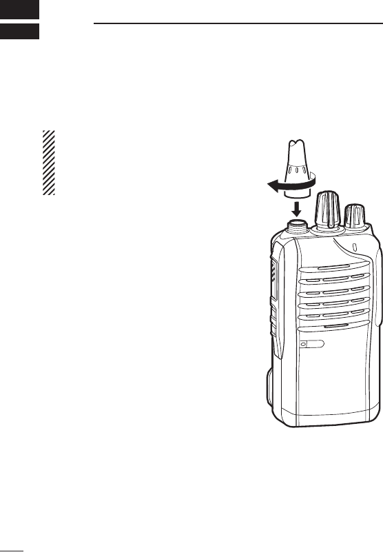
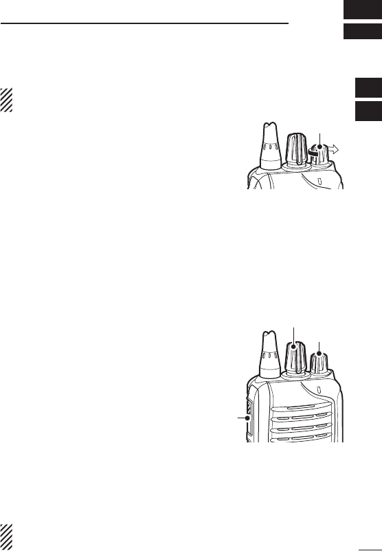
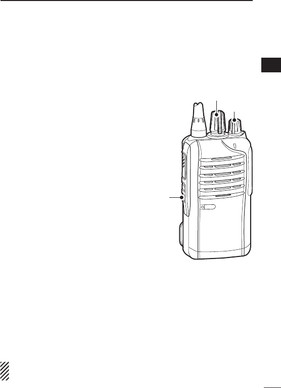
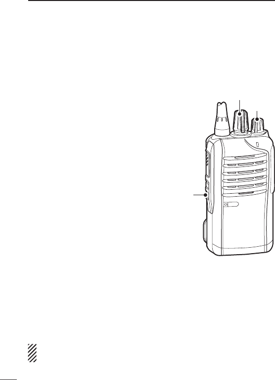
■ Accessory attachments
D Flexible antenna
Connect the flexible antenna to the antenna connector.
CAUTION:
•NEVER HOLD just the antenna
when carrying the transceiver.
•Transmittingwithoutanantennawill
damage the transceiver.
1
1ACCESSORIES
2
1
ACCESSORIES
1
2
3
4
5
6
7
8
9
10
11
12
13
14
15
16
17
18
19
20
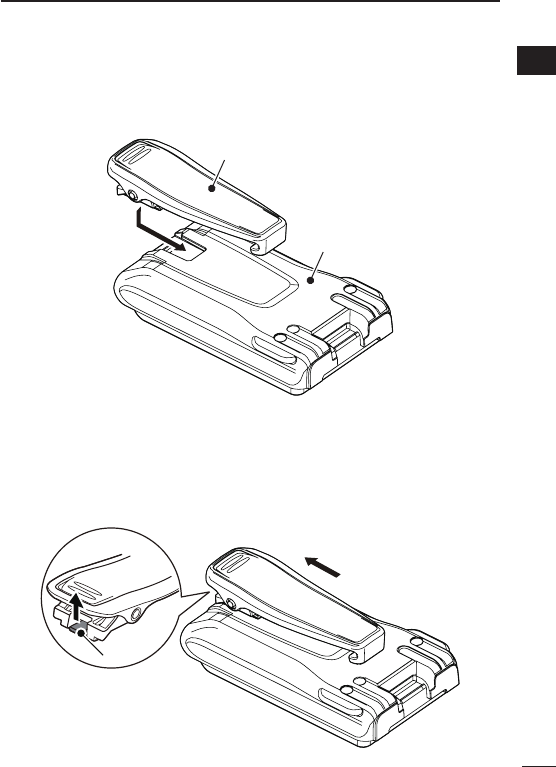
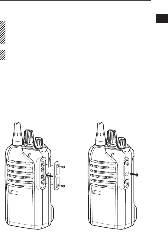
D Belt clip
To attach the belt clip:
➥ Slide the belt clip in the direction of the arrow until the belt clip
locks in place, and makes a ‘click’ sound.
Battery pack
Belt clip
To detach the belt clip:
q Remove the battery pack from the transceiver, if it is attached.
(p. 3)
w Lift the tab up (q), and slide the belt clip in the direction of the
arrow (w).
w
q
Ta b
3
1ACCESSORIES
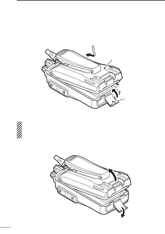
D Battery pack or case
To attach the battery pack or case:
q Fit the battery pack/case in the direction of the arrow, then close
it.
w Hook the latch until it makes a ‘click’ sound.
q
Latch
w
Battery pack/case
To remove the battery pack/case:
Be careful! The latch is tightly locked, so use caution when re-
leasing it. DO NOT use your finger nail. Use the edge of a coin
or screwdriver tip to carefully release it
.
q Unhook the latch.
w Lift up the
battery pack/case
in the direction of the arrow.
q
w
4
1
ACCESSORIES
1
2
3
4
5
6
7
8
9
10
11
12
13
14
15
16
17
18
19
20
NEVER remove or attach the
battery pack/case
when the trans-
ceiver is wet or soiled. This may result in water or dust getting into
the transceiver,
battery pack/case,
and may result in them being
damaged.
NOTE: Keep the battery terminals clean. It’s a good idea to clean
the battery terminals once a week.
D Jack cover
Attach the jack cover when the optional equipment is not used.
To attach the jack cover:
q Attach the jack cover to the
[SP MIC] jack.
w Tighten the screws.
To detach the jack cover:
q Remove the screws with a
phillips screwdriver.
w Detach the jack cover to con-
nect the optional equipment.
w
w
w
q
q
q
5
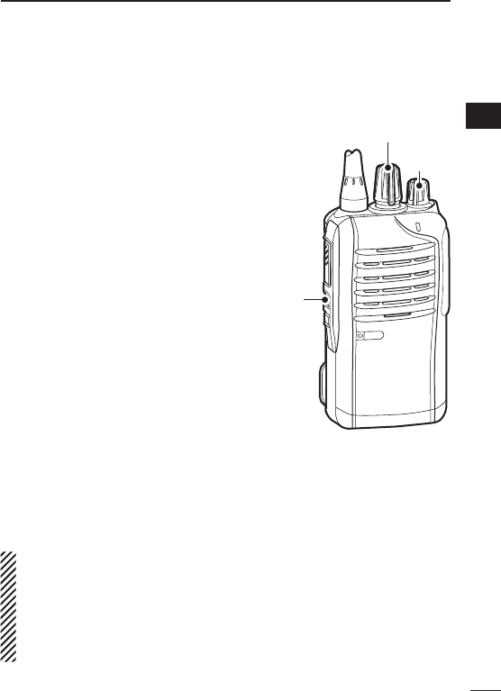
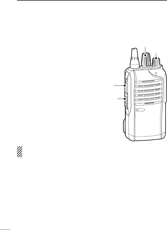
2PANEL DESCRIPTION
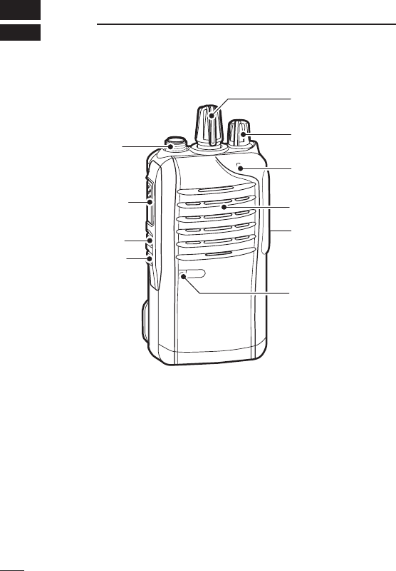
■ Front, top and side panels
Microphone
Speaker
r
w
e
q
y
u
i
tLOWER KEY
UPPER KEY
PTT SWITCH
ANTENNA
CONNECTOR
ROTARY
SELECTOR
LED INDICATOR
VOLUME
CONTROL
SPEAKER-
MICROPHONE
JACK
q ROTARY SELECTOR
Rotate to select the pre-programmed memory channels or scan
lists, depending on the pre-programming.
w VOLUME CONTROL [VOL]
Rotate to turn the power ON or OFF, and adjust the audio level.
6
2
PANEL DESCRIPTION
e LED INDICATOR (p. 7)
➥ Lights red* while transmitting.
* When the optional battery case is attached, the LED indicator
lights orange.
➥ Lights green while receiving a signal, or when the squelch is
open.
➥ Lights/blinks orange when the matched 2/5-tone code is re-
ceived, depending on the pre-programming.
r SPEAKER-MICROPHONE JACK [SP MIC]
Connect the optional speaker-microphone or VOX adapter
cable.
t LOWER KEY [Lower]
y UPPER KEY [Upper]
The desired function can be assigned by your dealer. (p. 8)
u PTT SWITCH [PTT]
Hold down to transmit; release to receive.
i ANTENNA CONNECTOR
Connect the antenna.
1
2
3
4
5
6
7
8
9
10
11
12
13
14
15
16
17
18
19
20
Jack cover
NOTE: Attach the jack cover
when the optional equipment
is not used. (p. 4)
7
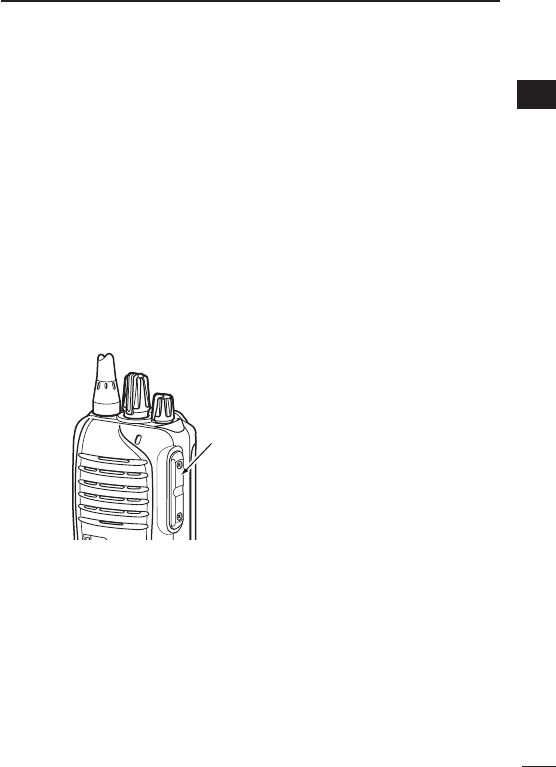
2PANEL DESCRIPTION
■ LED indicator
The LED indicator indicates the status of various
parameters of the transceiver as follows;
(Ref.; R=Red, G=Green, O=Orange)
R* R*
TX Low BATT2 R* R* R* R*
O
O O
G G G G
G G
G G G G G G G G
R G R G R G R G R G R G R G R G
R O R O R O R O R O R O R O R O
G
G G
Clone Err
Clone TX/RX
Low BATT1
Low BATT2
Busy
F/S Scan
Call LED Blink
Call LED ON
TX Low BATT1
R*
TX
•TX:LightsRedwhiletransmittingasignal.
•RX:LightsGreenwhilereceivingasignal.
•CallLED(ON):TurnsONwhilereceivingamatched2/5-tone.
•CallLED(Blink):Blinkswhilereceivingamatched2/5-tone.
•Fast/Slowscan:BlinkswhentheFast/Slowscanisactivated.
•LowBattery1:Youshouldchargethebattery.(blinksslowly)
•LowBattery2:Youmustchargethebattery.(blinksfast)
•TXlowBattery2:VeryLowBatterywasdetectedduringTXmode.
•ChannelError:Anon-programmedchannelisselected.
* Lights (or blinks) orange when the optional battery case is attached.
•TXlowBattery1:LowBatterywasdetectedduringTXmode.

8
2
PANEL DESCRIPTION
■ Programmable function keys
The following functions can be assigned to the [Upper] and [Lower]
programmable function keys.
Consult your Icom dealer or system operator for details concerning
your transceiver’s programming.
SCAN
Push to start and cancel the scanning operation.
•WhenthescanstartedwiththePowerONScanorAutoScanfunc-
tion, push to pause the scanning operation. The paused scan re-
sumes after the specified time period has passed.
PRIORITY A CHANNEL, PRIORITY B CHANNEL
Push to select the Priority A or Priority B channel.
PRIORITY A CHANNEL (REWRITE),
PRIORITY B CHANNEL (REWRITE)
➥ Push to select the Priority A or Priority B channel.
➥ Hold down [Prio A (Rewrite)] or [Prio B (Rewrite)] for 1 second to
assign the operating channel to Priority A or Priority B channel,
respectively.
MEMORY CHANNELS 1, 2, 3, 4
Push to directly select memory channel 1, 2, 3 or 4, if programmed.
Consult your dealer for details.
LONE WORKER (p. 24)
➥ Push to turn the Lone Worker function OFF.
➥ Hold down to turn the Lone Worker function ON.
•WhentheLoneWorkerfunctionisturnedON,andnooperationis
performed for the specified time period, the Emergency function is
automatically turned ON.
1
2
3
4
5
6
7
8
9
10
11
12
13
14
15
16
17
18
19
20

9
2PANEL DESCRIPTION
MONITOR, MONITOR (AUDIBLE)
➥ Push to turn the CTCSS (DTCS) or 2/5-tone squelch Mute ON
or OFF.
•Only during LMR operation, push to open any squelch func-
tions, or deactivate any mute functions.
•Only during PMR operation, push to activate one or two of the
following functions* on each channel.
- Hold down to un-mute the channel (Audible mode).
- Push to mute the channel (Inaudible mode).
- Push to send a ‘reset code’ after the communication is finished.
*Ask your dealer for details.
NOTE: The un-mute condition may automatically return to
the mute condition, after a specified time period.
➥ Depending on the presetting, holding down this key for 1 sec-
ond cancels a scan.
LOCK
Hold down to electronically lock all programmable keys except
[Moni(Audi)], [Call] (including Call A and Call B), [Emergency],
Surveillance] and [Lone Worker].
HIGH/LOW (p. 22)
Select the transmit output power level temporarily or permanently,
depending on the presetting.
•Askyourdealerfortheoutputpowerlevelforeachselection.
TALK AROUND
➥ Push to turn the Talk Around function OFF.
➥ Hold down to turn the Talk Around function ON.
•TheTalkAroundfunctionequalizesthetransmitfrequencytothe
receive frequency for transceiver-to-transceiver communication.
DTMF AUTODIAL
Push to transmit a programmed DTMF code.

10
2
PANEL DESCRIPTION
WIDE/NARROW
➥ Push to switch the IF bandwidth to Wide.
•Thewidepassbandwidthcanbeselectedfrom20or25kHzusing
the optional cloning software (PMR operation only). Ask your dealer
for details.
➥ Hold down to switch the IF bandwidth to Narrow.
CALL, CALL A, CALL B
Push to transmit a 2/5-tone code.
•Tonecalltransmissionmaybenecessarybeforeyoucallanothersta-
tion, depending on your signalling system.
•[CallA]and/or[CallB]keysmaybeavailablewhenyoursystemem-
ploys selective ‘Individual/Group’ calls. Ask your dealer which call is
assigned to each key.
EMERGENCY
Hold down for specified time period to transmit an emergency call.
•Theemergencycalltransmitswithbeeps,and the LED lights red.
•Thetransceivercan transmitan emergencycallwithout the beep
sounding and the LED indicator lighting. Ask your dealer for details.
•Ifyouwanttocanceltheemergencycall,holddownthekeyagain
before transmitting the call.
•Theemergencycallistransmittedonetimeonly,orrepeatedlyuntilre-
ceiving an acknowledgement signal, or until the power is turned OFF.
When a matched 5-tone code signal is received, the emergency func-When a matched 5-tone code signal is received, the emergency func-
tion can be cancelled depending on the presetting. (PMR operation
only)
SURVEILLANCE
➥ Push to turn the Surveillance function OFF.
➥ Hold down to turn the Surveillance function ON.
•WhenthisfunctionisturnedON,thebeepisnotheardandtheLED
does not light when a signal is received, or a key is pushed.
1
2
3
4
5
6
7
8
9
10
11
12
13
14
15
16
17
18
19
20

SIREN
Hold down for 1 second to emit a siren sound.
This function can be used for situations other than an emergency
alert, such as a security alarm for example.
The transceiver emits the siren sound until the power is turned
OFF.
ENCRYPTION
Push to turn the Voice Encryption function ON or OFF while operat-
ing in the digital mode.
ANNOUNCE
Push to turn the Channel Announce function ON or OFF.
•WhenthisfunctionisturnedON,thetransceiverannouncestheposi-
tion of [ROTARY SELECTOR] between 1 and 16 when rotating [RO-
TARY SELECTOR] to a desired scale.
11
2PANEL DESCRIPTION
12
3
BASIC OPERATION
1
2
3
4
5
6
7
8
9
10
11
12
13
14
15
16
17
18
19
20
■ Turning power ON
Prior to using the transceiver for the first time, the battery pack
must be fully charged for optimum life and operation. (p. 31)
➥Rotate [VOL] to turn power ON.
D Battery type selection
The battery type must be selected according to the battery pack or
case when it is changed, but only the first time it is used.
Check the battery type before you begin the selection procedure.
One to three beep(s) sound in sequence, so you must repeat the
steps until the number of beeps matches your battery type.
For example, if your battery type is a Li-ion battery pack, you must
repeat the procedure until one beep is heard.
q Set
[ROTARY SELECTOR] to any
channel other than Channel 16.
w Rotate [VOL] to turn OFF the trans-
ceiver’s power.
e
While holding down [PTT], rotate
[VOL] to turn ON the power.
•Youshouldhold[PTT]untilthebeep
sounds. (It takes approximately 5
second.)
•One beep sounds when the Li-ion
battery is selected.
•Twobeepssoundwhenthebatterycaseisselected.
•ThreebeepssoundwhentheNi-MHbatteryisselected.
r After the beep sounds, release [PTT].
t Repeat steps w to r until you select the attached battery type.
NOTE: This operation may not be available, depending on the
presetting. Ask your dealer for details.
[VOL]
[VOL]
[PTT]
[ROTARY SELECTOR]

■ Channel selection
Several types of channel selecting methods are available. They
may differ, according to your system set up.
To select a desired operating channel, do one of the following.
•Rotate[ROTARYSELECTOR].
•Pushoneofmemorychannelkeys,[MR-CH1]to[MR-CH4].
•Pushoneofthesekeys,[PrioA],[PrioB],[PrioA(Rewrite)]and
[Prio B (Rewrite)].
AUTOMATIC SCAN TYPE:
Selecting a channel is not necessary for this type. When turning ON
the power, the transceiver automatically starts scanning. Scanning
stops when a call is received.
NOTE: If the Move to Priority A channel at Power ON function
(p. 22) is turned ON, the transceiver does not start scanning at
power ON.
13
3BASIC OPERATION
14
3
BASIC OPERATION
1
2
3
4
5
6
7
8
9
10
11
12
13
14
15
16
17
18
19
20
■ Call procedure
When your system employs tone signalling (excluding CTCSS and
DTCS), the tone call procedure may be necessary prior to voice
transmission. The tone signalling that is employed in the transceiver
may be a selective calling system, which allows you to call only
specific station(s), and prevent unwanted stations from contacting
you.
q Select a desired TX code channel or 2/5-tone code, according to
your System Operator’s instructions.
•Thismaynotbenecessary,dependingonprogramming.
w Push [Call] (assigned to one of the dealer programmable keys.)
(p. 10)
e After transmitting a 2/5-tone code, the remainder of your com-
munication can be carried out normally.
Selective calling Non-selective calling

15
3BASIC OPERATION
■ Receiving and transmitting
CAUTION: Transmitting without an antenna will damage the
transceiver. See page 1 for antenna attachment.
Receiving:
q Rotate [VOL] to turn ON the power.
w Rotate [ROTARY SELECTOR], or push one of the memory chan-
nel keys, [MR-CH 1] to [MR-CH 4], to select a channel.
e When receiving a call, adjust the audio output to a comfortable
listening level.
NOTE: When a matched RX code signal is received, audio from
the microphone is automatically transmitted for a specified time
period.*
* Depending on the presetting. Ask your dealer for details.
Transmitting:
Wait for the channel to become clear to avoid interference.
q While holding down [PTT], speak into the microphone at a nor-
mal voice level.
w Release [PTT] to return to receive.
IMPORTANT: To maximize the readability of your signal;
1. Pause briefly after pushing [PTT].
2.
Hold the microphone 5 to 10 cm (2 to 4 inches) from your mouth,
then speak into the microphone at a normal voice level.

16
3
BASIC OPERATION
1
2
3
4
5
6
7
8
9
10
11
12
13
14
15
16
17
18
19
20
D Transmitting notes
• Transmit inhibit function
The transceiver has several inhibit functions, which restrict trans-
mission under the following conditions:
- The channel is muted. (PMR operation only)
- The channel is busy.
- A signal with the un-matched (or matched) CTCSS (or DTCS) tone
is received.
- The selected channel is a ‘receive only’ channel.
• Time-out timer
After continuously transmitting longer than the pre-programmed time
period, the time-out timer activates, and stops further transmitting.
• Penalty timer
Once the time-out timer activates, transmitting is further inhibited for
a time period determined by the penalty timer.
• PTTID call
The transceiver automatically sends the ID code (5-tone, DTMF,
BIIS, MDC system or IDAS operations) when [PTT] is pushed (be-
ginning of the transmission) and/or released (end of transmission),
depending on the presetting.

D DTMF transmission
If the transceiver has [DTMF Autodial] assigned to it, the automatic
DTMF transmission function is usable.
➥ Push [DTMF Autodial] to transmit the DTMF code.
D Receiving a Stun, Kill and Revive command
The dispatcher can send a 2/5-tone signal that will stun, kill or re-
vive your transceiver.
When the Stun command is received, a beep sounds*, and the
transceiver becomes unusable. Receiving a Revive command is
necessary to operate the transceiver again in this case.
When the Kill command is received, a beep sounds*, and the trans-
ceiver becomes unusable (the transceiver switches to the cloning
required condition). Cloning the transceiver is necessary to operate
the transceiver again in this case.
* Depending on the presetting. Ask your dealer for details.
17
3BASIC OPERATION
■ Setting the microphone gain
Adjusts the microphone gain.
q Rotate [VOL] to turn the trans-
ceiver power OFF.
w Set [ROTARY SELECTOR] to
Channel 16.
e While holding down [Upper], ro-
tate [VOL] to turn ON the power
and enter the microphone gain
adjustment mode.
r Push [Upper] to increase, or
push [Lower] to decrease the
microphone gain.
•Theadjustablerangeis1(mini-
mum) to 4 (maximum).
•A beep sounds after pushing
[Upper] or [Lower].
An error beep sounds if you try
to decrease more than 1 or try
to increase more than 4.
Therefore, you can determine the current level setting by the type
of beep that sounds.
t Rotate [VOL] to turn the power OFF, then ON again to exit the
microphone gain adjustment mode.
NOTE:
•Thisoperationmaynotbeavailable,dependingonthepreset-
ting. Ask your dealer for details.
•WhenusingtheVOXfunction,werecommendsettingthemi-
crophone gain to 3. However, you can adjust it to suit your op-
erating environment (including your headset performance).
18
3
BASIC OPERATION
1
2
3
4
5
6
7
8
9
10
11
12
13
14
15
16
17
18
19
20
[Upper]
[VOL]
[ROTARY SELECTOR]
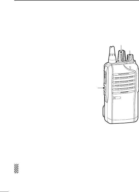
■ Setting the squelch level
The squelch circuit mutes the received audio signal, depending on
the signal strength.
q Rotate [VOL] to turn the trans-
ceiver power OFF.
w Set [ROTARY SELECTOR] to
any channel other than Chan-
nel 16.
e While holding down [Upper], ro-
tate [VOL] to turn ON the power
and enter the squelch level ad-
justment mode.
r Push [Upper] to increase the
squelch level (tight squelch), or
push [Lower] to decrease the
squelch level (loose squelch).
•Theadjustablerangeis0(loose
squelch) to 9 (tight squelch).
•A beep sounds after pushing
[Upper] or [Lower].
An error beep sounds if you try to decrease more than 0 or try to
increase more than 9.
Therefore, you can determine the current level setting by the type
of beep that sounds.
t Rotate [VOL] to turn the power OFF, then ON again to exit the
squelch level adjustment mode.
NOTE: This operation may not be available, depending on the
presetting. Ask your dealer for details.
19
3BASIC OPERATION
[VOL]
[Upper]
[ROTARY SELECTOR]
■ Setting the Beep level
The beep function can be turned ON or OFF, and its level can be
adjusted between 1 and 5, or 1 (linked) and 5 (linked). When a
Linked option is selected, the beep level is adjustable with [VOL].
q Rotate [VOL] to turn the trans-
ceiver power OFF.
w Set [ROTARY SELECTOR] to
any channel other than Chan-
nel 16.
e While holding down [Lower], ro-
tate [VOL] to turn ON the power
and enter the beep level adjust-
ment mode.
r Push [Upper] to change the beep
level, or push [Lower] to turn the
beep function ON or OFF.
•Theadjustablerangeis1to5or
1 (Linked) to 5 (Linked).
•Ifthelevelisseton1to4or1
(Linked) to 4 (Linked), pushing
[Upper] increases the level.
If the level is 5 or 5 (Linked), 1 (Linked) or 1 is selected after push-
ing [Upper], respectively.
•A beep sounds after pushing [Upper].Therefore, you can deter-
mine the current level setting by the type of beep that sounds.
•OnebeepsoundswhenthebeepfunctionisturnedONafterpush-
ing [Lower].
t Rotate [VOL] to turn the power OFF, then ON again to exit the
beep level adjustment mode.
NOTE: This operation may not be available, depending on the
presetting. Ask your dealer for details.
20
3
BASIC OPERATION
1
2
3
4
5
6
7
8
9
10
11
12
13
14
15
16
17
18
19
20
[VOL]
[Lower]
[ROTARY SELECTOR]
21
3BASIC OPERATION
■ Setting the Ringer level
The Ringer level can be adjusted between 1 and 5, or 1 (Linked)
and 5 (Linked). When a Linked option is selected, the Ringer level
is adjustable with [VOL].
q Rotate [VOL] to turn the trans-
ceiver power OFF.
w Set [ROTARY SELECTOR] to
Channel 16.
e While holding down [Lower], ro-
tate [VOL] to turn ON the power
and enter the Ringer level ad-
justment mode.
r Push [Upper] to increase, or
push [Lower] to decrease the
Ringer level.
•Theadjustablerangeis1to5or
1 (Linked) to 5 (Linked).
•If the level is set on 5 or 5
(Linked), pushing [Upper] selects
1 (Linked) or 1, respectively. If the
level is 1 or 1 (Linked), pushing
[Lower] selects 5 (Linked) or 5,
respectively.
•A beep sounds after pushing [Upper] or [Lower]. Therefore, you
can determine the current level setting by the type of beep that
sounds.
t Rotate [VOL] to turn the power OFF, then ON again to exit the
beep level adjustment mode.
NOTE: This operation may not be available, depending on the
presetting. Ask your dealer for details.
[VOL]
[Lower]
[ROTARY SELECTOR]

22
3
BASIC OPERATION
1
2
3
4
5
6
7
8
9
10
11
12
13
14
15
16
17
18
19
20
■ Output power level selection
If the transceiver has [High/Low] assigned to it, the transmit output
power level can be selected, depending on the presetting.
When the battery case is selected as the battery type, or the bat-
tery voltage drops to a low power level and the LED indicator sta-
tus is “Low Battery 2,” the output power automatically switches to
“Low 1.” (pp. 7, 12)
➥ Push [High/Low] to select the transmit output power level.
•Onebeepsoundswhen“Low1”isselected.
•Twobeepssoundwhen“Low2”isselected.
•Threebeepssoundwhen“High”isselected.
■ Priority A channel selection
When one of the following operations is performed, the transceiver
automatically selects the Priority A channel.
•TurningthepowerON
The Priority A channel is selected each time the transceiver pow-
er is turned ON.
•Autoreset
The Priority A channel is selected when the Auto Reset timer
ends.

23
3BASIC OPERATION
■ MDC 1200 system operation
The MDC 1200 signaling system enhances your transceiver’s capa-
bilities. It allows PTT ID* and Emergency signaling.
* When [PTT] is pushed and/or released, the transceiver transmits your
station ID.
D Transmitting an Emergency Call
The MDC 1200 system’s Emergency feature can be accessed
using the [Emergency] key. The transceiver will send an Emergency
MDC 1200 system command once, or repeatedly for a programmed
number of times until it receives an acknowledgement signal.
The emergency call can be transmitted without a beep sound, de-
pending on how the emergency function is programmed. Ask your
dealer for details.
■ Lone Worker Emergency Call
When the Lone Worker function is turned ON, and no operation is
performed for the specified time period*, the transceiver enters the
emergency mode, and then the countdown for the emergency call
transmission starts.
After the specified time period* has passed, an emergency call is
automatically transmitted once, or repeatedly*.
If someone operates the transceiver before the call is transmitted, the
transceiver exits the emergency mode, and the emergency call is can-
celled.
* Depending on the presetting. Ask your dealer for details.
q Hold down [Lone Worker] to turn ON the Lone Worker function.
w Push [Lone Worker] to turn OFF the Lone Worker function.

24
3
BASIC OPERATION
1
2
3
4
5
6
7
8
9
10
11
12
13
14
15
16
17
18
19
20
■ Emergency Call
When [Emergency] is held down for the specified time period*, the
emergency signal is transmitted once, or repeatedly, on the speci-
fied emergency channel.
A repeat emergency signal is automatically transmitted until you
turn the power OFF.
Depending on the pre-programmed settings, receiving a matching
5-tone code cancels the transmission.
When no emergency channel is specified, the signal is transmitted
on the previously selected channel.
If you want to cancel the emergency call, hold down [Emergency]
again before transmitting the call.
If your transceiver is programmed for Silent operation, you can
transmit an Emergency call without the beep sounding and the LED
indicator lighting.
IMPORTANT: It is recommended to set an emergency channel
individually to provide the certain emergency call operation.
D NOTES
Depending on the presetting, the following functions are automati-
cally activated. Ask your dealer for details.
• Auto TX function
After the emergency call transmission, audio from the microphone
is automatically transmitted for a specified time period.*
• Auto RX function
After the emergency call transmission, the transceiver stands by in
the audible mode for the specified time period.*
* Depending on the presetting. Ask your dealer for details.

25
4IDAS OPERATION
■ IDAS operation
The IC-F3100D series and IC-F4100D series provide Icom Digital
Advanced System (IDAS) that meets the 6.25 kHz emission mask
requirements for narrow banding, and increases efficiency of chan-
nel allocation and use of spectrum.
NOTE: During IDAS operation, BIIS 1200 and MDC 1200 sys-
tem operations are not available.
■ IDAS-Trunk operation
The IDAS-Trunk system enables further effective channel manage-
ment by sharing a minimum of channels with a large number of
users.
Rotate [ROTARY SELECTOR] to select the memory channel that is
programmed in the IDAS-Trunk zone.
NOTE: During IDAS-Trunk operation, you can receive and trans-
mit digital calls in the same way with the following IDAS opera-
tion.

26
4
IDAS OPERATION
1
2
3
4
5
6
7
8
9
10
11
12
13
14
15
16
17
18
19
20
■ Receiving a call
D Receiving a Call Alert
q When a Call Alert is received;
•Thetransceiverwillautomaticallytransmittheacknowledgement.
•TheLEDindicatorblinksorange.
•Beepssound.
w Hold down [PTT], then speak into the microphone.
e Release [PTT] to receive a response.
NOTE: The LED indicator or Beeps may differ, depending on the
presetting. Ask your dealer for details.
D Receiving a Stun, Kill or Revive
If an individual call with Stun or Kill command is received (RAN
code matching is not necessary depending on the presetting), the
transceiver will automatically transmit the acknowledgement, and
then you cannot receive* or transmit.
* Depending on the received Stun command setting.
➥ When a Stun command is received;
•Thetransceivercannotbeoperateduntiltheindividualcallwith
Revive command is received (RAN code matching is not nec-
essary depending on the presetting) or until the data cloning is
performed.
•Evenif[ROTARYSELECTOR]ischanged,thetransceiverwill
keep the same channel as the Stun command is received.
➥ When a Kill command is received;
•TheLEDindicatoralternatelyblinksredandgreen.
•The transceiver cannot be operated until the data cloning is
performed. Ask your dealer for details.
NOTE: Depending on the presetting, the transceiver ignores the
Stun, Revive and Kill commands, which are from a non-specified
station.

27
4IDAS OPERATION
D Receiving a Remote Monitor or Radio Check Call
If an individual call with Remote monitor or Radio check command
is received (RAN code matching is not necessary depending on the
presetting), the transceiver will automatically transmit.
➥ When a Remote monitor command is received;
•The transceiver will automatically transmit the acknowledge-
ment, and then it transmits the microphone audio for the set
time period.
➥ When a Radio check command is received;
•The transceiver will automatically transmit the acknowledge-
ment.

28
4
IDAS OPERATION
1
2
3
4
5
6
7
8
9
10
11
12
13
14
15
16
17
18
19
20
■ Transmitting a call
IDAS operation allows you to make a call to a specific station (In-
dividual call) or to a particular group (Talkgroup call). Other digital
mode transceivers on the channel will not receive a call that does
not match their individual or talkgroup ID and/or RAN (Radio Ac-
cess Number) code.
D Transmitting an Emergency Call
When [Emergency] is held down for the specified time period, the
emergency signal (digital command) is transmitted once or repeat-
edly* on the specified emergency channel. When no emergency chan-
nel is specified, the signal is transmitted on the operating channel.
* When the Repeat Cancel function is ON, the transceiver cancels
repeating after receiving an acknowledgement.
When the Repeat Cancel function is OFF, the transceiver repeats
calling according to the number of repeat cycles, even after re-
ceiving an acknowledgement.
Individual or Talkgroup call types of emergency calls can be pre-
fixed. If the call type is not pre-fixed, the default or selected call
type is used.
If you want to cancel the emergency call, hold down [Emergency]
again before transmitting the call.
If your transceiver is programmed for Silent operation, you can
transmit an Emergency call without the beep sounding and the LED
indicator lighting.
The transceiver can also be programmed to keep the microphone
open during an emergency call, allowing monitoring of the situation.
Ask your dealer for details.

29
4IDAS OPERATION
IMPORTANT: It is recommended to set an emergency channel
individually to provide the certain emergency call operation.
NOTE: The Digital Request Ack function is activated, the trans-
ceiver transmits the emergency call with the request to send
back an acknowledgment.

30
4
IDAS OPERATION
1
2
3
4
5
6
7
8
9
10
11
12
13
14
15
16
17
18
19
20
■ Position data transmission
When an optional HM-171GP or any other GPS receiver is con-
nected to the transceiver, the position (longitude and latitude) data
can be transmitted automatically when;
•AftersendingaStatusCall
- Set the ‘Send with Status Call’ item as ‘Enable.’
•AftersendinganEmergencyCall
- Set the ‘Send with Emergency’ item as ‘Enable.’
•AftersendingaVoiceCall
- Set the ‘Send with Voice Call’ item as ‘Enable.’
Ask your dealer or system operator for connection details.
■ Status message transmission
The status message can be transmitted automatically.
The status message is transmitted when the transceiver is turned
ON or OFF.
- Select a status message to be transmitted in ‘Power ON Status’
or ‘Power OFF Status’ item, respectively.
- Select a target station ID in ‘Power Status ID’.
■ Encryption function
The encryption function enables voice scrambling, which provides
private digital communication between stations.
Push [Encryption] to turn the encryption function ON or OFF.

31
5BATTERY CHARGING
■ Caution (for the BP-264 ni-m h b at t e r y )
R DANGER! NEVER short terminals (or charging terminals) of the
battery pack. Also, current may flow into nearby metal objects such
as a necklace, so be careful when placing battery packs (or the
transceiver) in handbags, etc.
Simply carrying with or placing near metal objects such as a neck-
lace, etc. may cause shorting. This may damage not only the bat-
tery pack, but also the transceiver.
R DANGER! NEVER incinerate used battery packs. Internal bat-
tery gas may cause an explosion.
R DANGER! NEVER immerse the battery pack in water. If the bat-
tery pack becomes wet, be sure to wipe it dry BEFORE attaching
it to the transceiver.
CAUTION: Always use the battery within the specified temperature
range, –5˚C to +60˚C (+23˚F to +140˚F). Using the battery out of its
specified temperature range will reduce the battery’s performance
and battery life.
CAUTION: Shorter battery life could occur if the battery is left com-
pletely discharged, or in an excessive temperature environment
(above +55˚C; +131˚F) for an extended period of time. If the battery
must be left unused for a long time, it must be detached from the
radio after charging. Keep it safely in a cool dry place at the follow-
ing temperature range:
–20˚C to +45˚C (–4˚F to +113˚F) (up to a month)
–20˚C to +35˚C (–4˚F to +95˚F) (up to six months)
–20˚C to +25˚C (–4˚F to +77˚F) (up to a year*)
* We recommend charging the battery pack every 6 months.
Clean the battery terminals to avoid rust or misscontact.
Keep the battery terminals clean. It’s a good idea to clean the bat-
tery terminals once a week.

32
5
BATTERY CHARGING
1
2
3
4
5
6
7
8
9
10
11
12
13
14
15
16
17
18
19
20
If your Ni-MH battery pack seems to have no capacity, even after
being charged, completely discharge it by leaving the power ON
overnight. Then, fully charge the battery pack again. If the battery
pack still does not retain a charge (or only very little charge), a new
battery pack must be purchased. (p. 43)
Prior to using the transceiver for the first time, the battery pack
must be fully charged for optimum life and operation.
•Recommendedtemperaturerangeforcharging:
between +10°C and +40°C (rapid charge: with BC-191) or
between 0°C and +45°C (regular charge: with BC-192)
•Usethesuppliedchargeroroptionalcharger(BC-191forrapid
charging, BC-192 for regular charging) only. NEVER use other
manufacturers’ chargers.
The battery pack contains a rechargable battery.
Charge the battery pack before first operating the transceiver, or
when the battery pack becomes exhausted.
If you want to prolong the battery life, the following points should
be observed:
•Avoidovercharging.ThechargingtimeperiodbytheBC-192
should be less than 48 hours.
•Use thebattery pack until itbecomes almost completelyex-
hausted, under normal conditions. We recommend battery charg-
ing after transmitting becomes impossible.

■ Caution (for the BP-265 Li-ion b at t e r y )
Misuse of Li-ion batteries may result in the following hazards:
smoke, fire, or the battery may rupture. Misuse can also cause
damage to the battery or degradation of battery performance.
R DANGER! NEVER short terminals (or charging terminals) of the
battery pack. Also, current may flow into nearby metal objects such
as a necklace, so be careful when placing battery packs (or the
transceiver) in handbags, etc.
Simply carrying with or placing near metal objects such as a neck-
lace, etc. may cause shorting. This may damage not only the bat-
tery pack, but also the transceiver.
D Battery caution
R DANGER! DO NOT hammer or otherwise impact the battery. Do
not use the battery if it has been severely impacted or dropped, or if
the battery has been subjected to heavy pressure. Battery damage
may not be visible on the outside of the case. Even if the surface
of the battery does not show cracks or any other damage, the cells
inside the battery may rupture or catch fire.
R DANGER! NEVER use or leave battery packs in areas with
temperatures above +60˚C (+140˚F). High temperature buildup in
the battery, such as could occur near fires or stoves, inside a sun
heated car, or in direct sunlight may cause the battery to rupture or
catch fire. Excessive temperatures may also degrade battery per-
formance or shorten battery life.
R DANGER! DO NOT expose the battery to rain, snow, seawater,
or any other liquids. Do not charge or use a wet battery. If the bat-
tery gets wet, be sure to wipe it dry before using. The battery is not
waterproof.
33
5BATTERY CHARGING

34
5
BATTERY CHARGING
1
2
3
4
5
6
7
8
9
10
11
12
13
14
15
16
17
18
19
20
R DANGER! NEVER incinerate used battery packs, since internal
battery gas may cause them to rupture, or may cause an explosion.
R DANGER! NEVER solder the battery terminals or NEVER mod-
ify the battery pack. This may cause heat generation, and the bat-
tery may rupture, emit smoke or catch fire.
R DANGER! Use the battery only with the transceiver for which it
is specified. Never use a battery with any other equipment, or for
any purpose that is not specified in this instruction manual.
R DANGER! If fluid from inside the battery gets in your eyes, blind-
ness can result. Rinse your eyes with clean water, without rubbing
them, and see a doctor immediately.
R
WARNING! Immediately stop using the battery if it emits an ab-
normal odor, heats up, or is discolored or deformed. If any of these
conditions occur, contact your Icom dealer or distributor.
R
WARNING! Immediately wash, using clean water, any part of
the body that comes into contact with fluid from inside the battery.
R
WARNING! NEVER put the battery in a microwave oven, high-
pressure container, or in an induction heating cooker. This could
cause a fire, overheating, or cause the battery to rupture.
CAUTION: Always use the battery within the specified temperature
range, –20˚C to +60˚C (–4˚F to +140˚F). Using the battery out of its
specified temperature range will reduce the battery’s performance
and battery life.

35
5BATTERY CHARGING
CAUTION: Shorter battery life could occur if the battery is left fully
charged, completely discharged, or in an excessive temperature
environment (above +50˚C; +122˚F) for an extended period of time.
If the battery must be left unused for a long time, it must be de-
tached from the radio after discharging.
You may use the battery until the remaining capacity is about half,
then keep it safely in a cool dry place within the temperature range
as shown below:
–20˚C to +50˚C (–4˚F to +122˚F) (up to a month)
–20˚C to +35˚C (–4˚F to +95˚F) (up to three months)
–20˚C to +20˚C (–4˚F to +68˚F) (up to a year)
D Charging caution
R DANGER! NEVER charge the battery pack in areas with ex-
tremely high temperatures, such as near fires or stoves, inside
a sun heated car, or in direct sunlight. In such environments, the
safety/protection circuit in the battery will activate, causing the bat-
tery to stop charging.
R
WARNING! DO NOT charge or leave the battery in the battery
charger beyond the specified time for charging. If the battery is not
completely charged by the specified time, stop charging and re-
move the battery from the battery charger. Continuing to charge the
battery beyond the specified time limit may cause a fire, overheat-
ing, or the battery may rupture.
R
WARNING! NEVER insert the transceiver (battery attached to
the transceiver) into the charger if it is wet or soiled. This could
corrode the battery charger terminals or damage the charger. The
charger is not waterproof.
CAUTION: DO NOT charge the battery outside of the specified
temperature range: BC-193 (+10˚C to +40˚C; +50˚F to +104˚F).
Icom recommends charging the battery at +20˚C (+68˚F). The bat-
tery may heat up or rupture if charged out of the specified tempera-
ture range. Additionally, battery performance or battery life may be
reduced.
36
5
BATTERY CHARGING
1
2
3
4
5
6
7
8
9
10
11
12
13
14
15
16
17
18
19
20
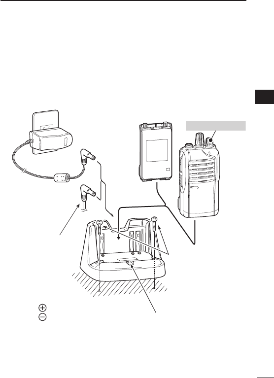
■ Battery chargers
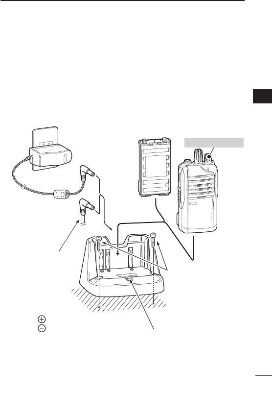
D Using the BC-191 to rapid charge the BP-264
The BC-191 provides rapid charging of the Ni-MH battery pack
(BP-264 only). Never use for any other battery pack.
Charging time period: Approximately 2 hours (for the BP-264)
The following item is additionally required:
•AnACadapter(notsuppliedwithsomeversions)ortheDCpower
cable (OPC-515L/CP-23L).
Status indicator
• Lights orange:
While charging.
• Lights green:
Charging is completed.
AC adapter
(A different type,
or no AC adapt-
er is supplied,
depending on
the version.)
About OPC-515L
White line:
Black line :
CAUTION: NEVER connect the
OPC-515L to a power source
using reverse polarity.
This will ruin the battery charger.
*
Battery packTransceiver
Tu rn power OFF
Optional OPC-515L*
(for power source) or
CP-23L (for 12 V cig-
arette lighter socket)
can be used instead
of the AC adapter.
Screws*
( Self tapping screw:
M3.5 × at least 30 mm)
*Purchase separately.
Using screws is recom-
mended to secure the
charger.
37
5BATTERY CHARGING
D Using the BC-192 to regular charge the BP-264
The BC-192 provides regular charging of the Ni-MH battery pack
(BP-264 only). Never use for any other battery pack.
Charging time period (with BC-147S): Approximately 16 hours (for
the BP-264)
The following item is additionally required:
•AnACadapter(notsuppliedwithsomeversions)ortheDCpower
cable (OPC-515L).
AC adapter
(A different type,
or no AC adapt-
er is supplied,
depending on
the version.)
Charging time period differs
depending on the input voltage.
12 V
13.8 V
16 V
: Approx. 36 hours
: Approx. 21 hours
: Approx. 16 hours
About OPC-515L
White line:
Black line :
CAUTION: NEVER connect the
OPC-515L to a power source
using reverse polarity.
This will ruin the battery charger.
*
Battery packTransceiver
Tu rn power OFF
Optional OPC-515L*
(for power source)
can be used instead
of the AC adapter. Screws*
( Self tapping screw:
M3.5 × at least 30 mm)
*Purchase separately.
Using screws is recom-
mended to secure the
charger.
Status indicator
Lights green while charging.
NOTE:
The status indicator will not go
out even after a battery pack is
fully charged.
38
5
BATTERY CHARGING
1
2
3
4
5
6
7
8
9
10
11
12
13
14
15
16
17
18
19
20
D Using the BC-193 to rapid charge the BP-265
The BC-193 provides rapid charging of the Li-ion battery pack
(BP-265 only). Never use for any other battery pack.
Charging time period: Approximately 2.5 hours (for the BP-265)
The following item is additionally required:
•AnACadapter(notsuppliedwithsomeversions)ortheDCpower
cable (OPC-515L/CP-23L).
Status indicator
• Lights orange:
While charging.
• Lights green:
Charging is completed.
AC adapter
(A different type,
or no AC adapt-
er is supplied,
depending on
the version.)
About OPC-515L
White line:
Black line :
CAUTION: NEVER connect the
OPC-515L to a power source
using reverse polarity.
This will ruin the battery charger.
*
Battery packTransceiver
Tu rn power OFF
Optional OPC-515L*
(for power source) or
CP-23L (for 12 V cig-
arette lighter socket)
can be used instead
of the AC adapter.
Screws*
( Self tapping screw:
M3.5 × at least 30 mm)
*Purchase separately.
Using screws is recom-
mended to secure the
charger.
39
5BATTERY CHARGING
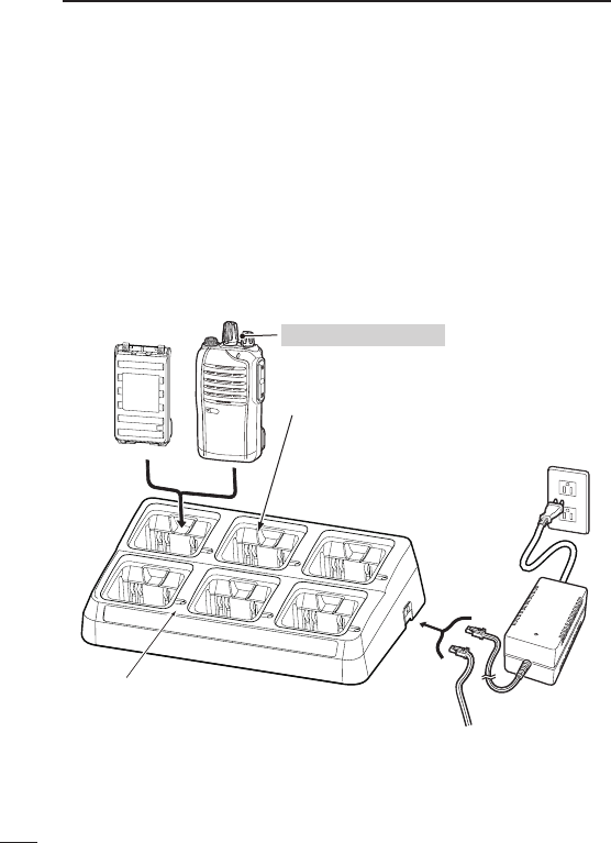
D Using the BC-197 to rapid charge the BP-264 or
BP-265
The BC-197 rapidly charges up to six battery packs.
Charging time for BP-264: Approximately 2 hours
Charging time for BP-265: Approximately 2.5 hours
The following additional item is required:
•AnACadapter(notsuppliedwithsomeversions)ortheDCpower
cable (OPC-656)
(An AC adapter is
not supplied with
some versions.)
AC adapter
(Connect to a DC power supply;
12 to 16 V/at least 7 A)
Red line : + Black line : _
Transceiver
Battery pack Tu rn OFF the power
Status indicator
(each indicator independently functions)
Charger adapters* are
installed in each slot.
The shape of charger adapter depends
on the version of the BC-197.
*
DC power cable (OPC-656)

40
5
BATTERY CHARGING
1
2
3
4
5
6
7
8
9
10
11
12
13
14
15
16
17
18
19
20
There are two types of BC-197 chargers for the IC-F3100D series
or IC-F4100D series; one is for Ni-MH batteries, and the other is for
Li-ion batteries.
Before you purchase a BC-197, check the type of battery you are
using, and then be sure to choose the suitable charger.
BC-197 Charger Type Chargeable Battery
With AD-120* charger adapters BP-264 Ni-MH battery
With AD-121* charger adapters BP-265 Li-ion battery
* The type of the charger adapter, AD-120 or AD-121 is printed on the
inside bottom of the charger adapter, and the type of battery it holds is
printed on the top right corner of the adapter.
41
5BATTERY CHARGING
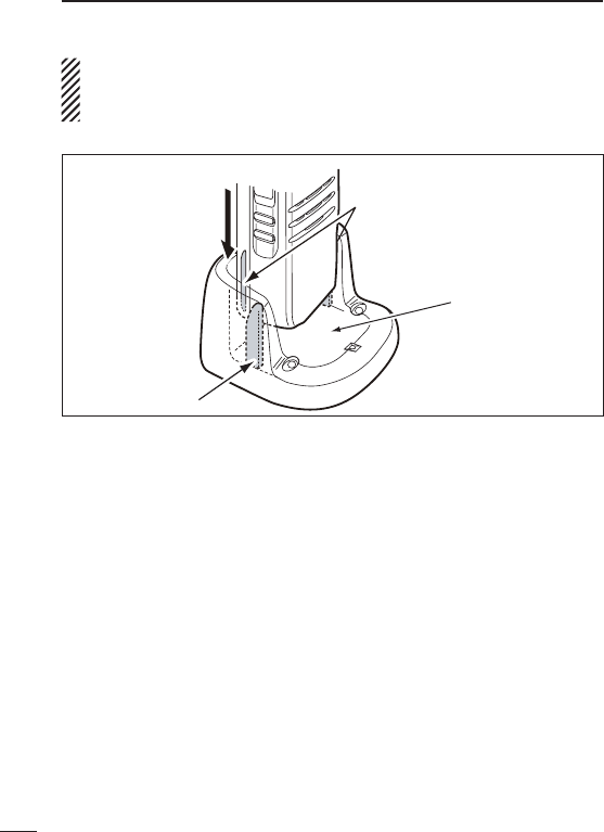
IMPORTANT:
Ensure the tabs on the battery pack are correctly aligned with
the guide rails inside the charger.
Guide rail
Tabs
BC-191, BC-192, BC-193
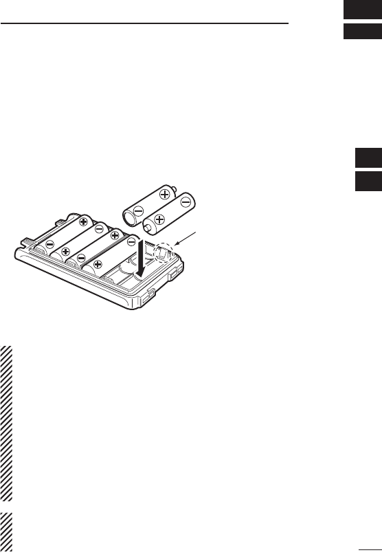
■ Optional battery case (BP-263)
When using the optional battery case, install 6 × AA (LR6) size
alkaline batteries, as illustrated below.
q Remove the battery case, if it is attached. (pp. 3, 4)
w Install 6 × AA (LR6) size alkaline batteries.
•Installonlyalkalinebatteries.
•Besuretoobservethecorrectpolarity.
e Attach the battery case. (pp. 3, 4)
CAUTION:
•Wheninstalling batteries,make sure theyareall thesame
brand, type and capacity. Also, do not mix new and old batter-
ies together.
•Keepthebatteryterminalsclean.It’sagoodideatocleanthe
battery terminals once a week.
•Neverincinerateusedbatterycellssinceinternalbatterygas
may cause them to rupture.
•Neverexposeadetachedbatterycasetowater.Ifthebattery
case gets wet, be sure to wipe it dry before using it.
•Neverusebatterieswhoseinsulatedcoverisdamaged.
NOTE: When the optional battery case is attached, the battery
type must be selected as “Battery case operation” when turning
the transceiver ON. Ask your dealer for details. (p. 12)
42
6
BATTERY CASE
1
2
3
4
5
6
7
8
9
10
11
12
13
14
15
16
17
18
19
20
Be careful! The negative
terminals of the battery case
protrude from the body, so
pay attention not to injure
your fingers when inserting
the batteries.

D BATTERY PACK
Battery pack Voltage Capacity Battery life*1
BP-263 Battery case for
AA (LR6) × 6 alkaline —*2
BP-264 7.2 V 1400 mAh (typ.) VHF 12 hrs.
UHF 11.3 hrs.
BP-265 7.4 V 1900 mAh (min.)
2000 mAh (typ.)
VHF 17.5 hrs.
UHF 16.1 hrs.
*1
When the power save function is turned ON, and the operating time
is calculated under the following conditions;
TX : RX : standby = 5 : 5 : 90
*2 The average operating time depends on the alkaline cells used.
D BELT CLIPS
• MB-124 b e Lt c L i p
Exclusive alligator-type belt clip.
D CHARGERS
• BC-191 d e s k t o p c h a r g e r + BC-123S a c a d a p t e r
For rapid charging of the Ni-MH battery pack. An AC adapter is
supplied with the charger, depending on the version.
Charging time period: approximately 2 hours for the BP-264.
• BC-192 d e s k t o p c h a r g e r + BC-147S a c a d a p t e r
For regular charging of the Ni-MH battery pack. An AC adapter is
supplied with the charger, depending on the version.
Charging time period: approximately 16 hours for the BP-264.
• BC-193 d e s k t o p c h a r g e r + BC-123S a c a d a p t e r
For rapid charging of the Li-ion battery pack. An AC adapter is
supplied with the charger, depending on the version.
Charging time period: approximately 2.5 hours for the BP-265.
43
7OPTIONS

44
7
OPTIONS
1
2
3
4
5
6
7
8
9
10
11
12
13
14
15
16
17
18
19
20
• BC-197 m u L t i -c h a r g e r
For rapid
simultaneously
charging of up to six battery packs
.
An
AC adapter may
be supplied with the charger, depending on the
version.
There are two types of BC-197 chargers for the IC-F3100D/
IC-F4100D series.
BC-197 Charger Type Chargeable Battery Charging time
With AD-120* BP-264 Ni-MH battery Approx. 2 hrs.
With AD-121* BP-265 Li-ion battery Approx. 2.5 hrs.
* Either AD-120 or AD-121 charger adapters are installed in the BC-
197, depending on the chargeable battery pack.
D DC POWER CABLES
• CP-23L c i g a r e t t e L i g h t e r c a b L e
Allows charging of the battery pack through a 12 V cigarette lighter
socket. (For BC-191/BC-193)
• OPC-515L/OPC-656 d c p o w e r c a b L e
For charging of the battery packs using a 12 V DC power source
instead of the AC adapter.
(OPC-515L for BC-191/BC-192/BC-193: OPC-656 for BC-197)
D ANTENNAS
• FA-SC73US/FA-SC56VS/FA-SC57VS s t u b b y a n t e n n a s
FA-SC73US : 450–490 MHz FA-SC56VS : 150–162 MHz
FA-SC57VS : 160–174 MHz
• FA-SC25U/FA-SC57U/FA-SC72U/
FA-SC25V/FA-SC55V a n t e n n a s
FA-SC25U : 400–430 MHz FA-SC57U : 430–470 MHz
FA-SC72U : 470–520 MHz FA-SC25V : 136–155 MHz
FA-SC55V : 146–174 MHz
• FA-SC61VC/FA-SC61UC c u t a n t e n n a s
FA-SC61VC : 136–174 MHz FA-SC61UC : 380–520 MHz

45
7OPTIONS
D OTHER OPTIONS
• AD-98FSC a n t e n n a c o n n e c t o r c o n v e r t e r
Allows you to connect an external antenna with a BNC connector.
• HM-158L/HM-159L s p e a k e r -m i c r o p h o n e
Combination speaker-microphone that provides convenient op-
eration while hanging the transceiver on your belt.
• HM-171GP s p e a k e r -m i c r o p h o n e
GPS speaker-microphone for BIIS and Digital modes operation.
• HS-94/HS-95/HS-97 h e a d s e t + OPC-2004 p L u g a d a p t e r c a b L e
HS-94 : Ear hook type
HS-95 : Neck-arm type
HS-97 : Throat microphone
OPC-2004 : Allows you to connect the HS-94/HS-95/HS-97 to the
transceiver. After connection, the VOX function can
be used.
• SP-27 t u b e e a r p h o n e
Provides clear audio in noisy environments.
Approved Icom optional equipment is designed for optimal performance
when used with an Icom transceiver.
Icom is not responsible for the destruction or damage to an Icom trans-
ceiver in the event the Icom transceiver is used with equipment that is
not manufactured or approved by Icom.
Some options may not be available in some countries. Please ask your
dealer for details.
46
7
OPTIONS
1
2
3
4
5
6
7
8
9
10
11
12
13
14
15
16
17
18
19
20
■ VOX function
The transceiver has a VOX function, which allows you hands-free
operation.
An optional headset (HS-94/HS-95/HS-97) and a plug adapter
cable (OPC-2004) are additionally required for operation.
•The VOX (voice operated transmission) function starts transmitting
when you speak into the microphone, without needing to push the PTT
switch; then, automatically returns to receive when you stop speak-
ing.
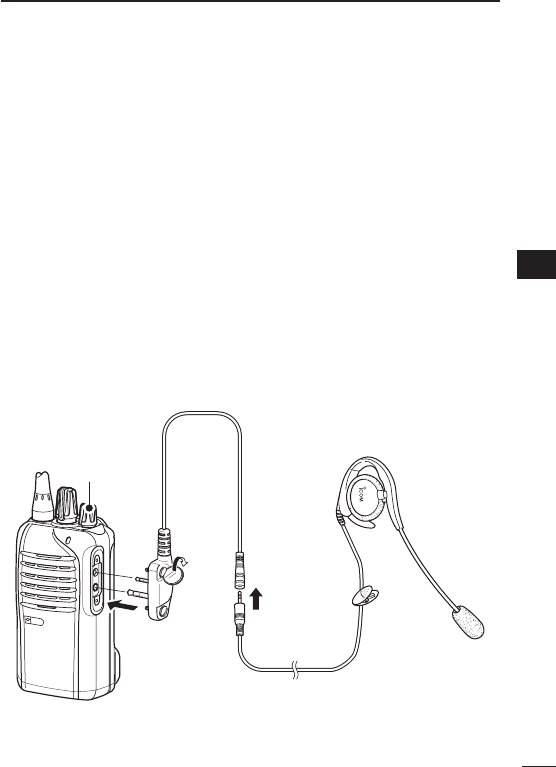
D Optional unit connection
q Rotate [VOL] to turn the transceiver power OFF.
w Remove the jack cover. (p. 4)
e Connect the optional headset (HS-94, HS-95 or HS-97) and
OPC-2004 as described below.
HS-94
OPC-2004
q
w
e
[VOL]
47
7OPTIONS
D Turning the VOX function ON or OFF
The VOX function can be turned ON or OFF when turning the trans-
ceiver power ON.
q Rotate [VOL] to turn the trans-
ceiver power OFF.
w Set [ROTARY SELECTOR] to
any channel other than Chan-
nel 16.
e While holding down [PTT] and
[Upper], rotate [VOL] to turn ON
the power to switch the VOX
function ON or OFF.
•OnebeepsoundswhentheVOX
function is turned OFF.
•TwobeepssoundwhentheVOX
function is turned ON.
NOTE: This operation may not be available, depending on the
presetting. Ask your dealer for details.
[VOL]
[Upper]
[PTT]
[ROTARY SELECTOR]
48
7
OPTIONS
1
2
3
4
5
6
7
8
9
10
11
12
13
14
15
16
17
18
19
20
D Setting the VOX gain
The VOX sensitivity level can be adjusted from 1 (minimum) to 10
(maximum).
q Connect the optional headset
(HS-94, HS-95 or HS-97) and
OPC-2004. (p. 46)
w Rotate [VOL] to turn the trans-
ceiver power OFF.
e Set [ROTARY SELECTOR] to
Channel 16.
r While holding down [PTT] and
[Upper], rotate [VOL] to turn ON
the power and enter the VOX
gain adjustment mode.
t Push [Upper] to increase, or
push [Lower] to decrease the
VOX gain while speaking into
the optional headset.
•Theadjustablerangeis1(mini-
mum) to 10 (maximum).
•Abeepsoundsafterpushing[Upper]or[Lower].
If the level is set on 1 or 10, an error beep sounds after pushing.
Therefore, you can determine the current level setting by the type
of beep that sounds.
y Rotate [VOL] to turn the power OFF, then ON to exit the VOX
gain adjustment mode.
NOTE:
•Thisoperationmaynotbeavailable,dependingonthepreset-
ting. Ask your dealer for details.
•Set the microphone gain before setting the VOX gain. (p. 18)
[VOL]
[Upper]
[PTT]
[ROTARY SELECTOR]

WARNING
Your Icom radio generates RF electromagnetic energy
during transmit mode. This radio is designed for and
classified as “Occupational Use Only”, meaning it must
be used only during the course of employment by indi-
viduals aware of the hazards, and the ways to minimize
such hazards. This radio is NOT intended for use by the
“General Population” in an uncontrolled environment.
This radio has been tested and complies with the FCC
RF exposure limits for “Occupational Use Only”. In addition, your Icom
radio complies with the following Standards and Guidelines with regard
to RF energy and electromagnetic energy levels and evaluation of such
levels for exposure to humans:
•FCCOETBulletin65Edition97-01SupplementC,Evaluating
Compliance with FCC Guidelines for Human Exposure to Radio
Frequency Electromagnetic Fields.
•AmericanNationalStandardsInstitute(C95.1-1992),IEEEStandard
for Safety Levels with Respect to Human Exposure to Radio Fre-
quency Electromagnetic Fields, 3 kHz to 300 GHz.
•AmericanNationalStandardsInstitute(C95.3-1992),IEEERecom-
mended Practice for the Measurement of Potentially Hazardous
Electromagnetic Fields– RF and Microwave.
•The accessories (antennas, batteries, belt clips, speaker-micro-
phone, etc. that is listed on pages 43–45) are authorized for use
with this product. Use of accessories other than those specified may
result in RF exposure levels exceeding the FCC requirements for
wireless RF exposure.
CAUTION
To ensure that your expose to RF electromagnetic
energy is within the FCC allowable limits for occu-
pational use, always adhere to the following guide-
lines:
49
8
SAFETY TRAINING INFORMATION

50
8
SAFETY TRAINING INFORMATION
1
2
3
4
5
6
7
8
9
10
11
12
13
14
15
16
17
18
19
20
•DO NOT operate the radio without a proper antenna attached, as
this may damaged the radio and may also cause you to exceed FCC
RF exposure limits. A proper antenna is the antenna supplied with
this radio by the manufacturer or antenna specifically authorized by
the manufacturer for use with this radio.
•DO NOT transmit for more than 50% of total radio use time (“50%
duty cycle”). “50% duty cycle” is also applicable to VOX/PTT mode.
Transmitting more than 50% of the time can cause FCC RF expo-
sure compliance requirements to be exceeded. The radio is trans-
mitting when the “LED indicator” lights red. You can cause the radio
to transmit by pressing the “PTT” switch or VOX function.
•ALWAYS keep the antenna at least 2.5 cm (1 inch) away from the
body when transmitting and only use the Icom belt-clip which is
listed on page 43 when attaching the radio to your belt, etc., to en-
sure FCC RF exposure compliance requirements are not exceeded.
To provide the recipients of your transmission the best sound qual-
ity, hold the antenna at least 5 cm (2 inches) from your mouth, and
slightly off to one side.
The information listed above provides the user with the information
needed to make him or her aware of RF exposure, and what to do to as-
sure that this radio operates with the FCC RF exposure limits of this radio.
Electromagnetic Interference/Compatibility
During transmissions, your Icom radio generates RF energy that can
possibly cause interference with other devices or systems. To avoid such
interference, turn off the radio in areas where signs are posted to do so.
DO NOT operate the transmitter in areas that are sensitive to electro-
magnetic radiation such as hospitals, aircraft, and blasting sites.
Occupational/Controlled Use
The radio transmitter is used in situations in which persons are exposed as
consequence of their employment provided those persons are fully aware
of the potential for exposure and can exercise control over their exposure.

MEMO

MEMO
1
2
3
4
5
6
7
8
9
10
11
12
13
14
15
16
17
18
19
20

MEMO

1
2
3
4
5
6
7
8
9
10
11
12
13
14
15
16
17
18
19
20
MEMO

1-1-32 Kamiminami, Hirano-ku, Osaka 547-0003, Japan
A-6884D-1EX
Printed in Japan
© 2010 Icom Inc.
Printed on recycled paper with soy ink.