ICOM orporated 333212 UHF Digital Transceiver User Manual IC F5020 F6020 series Instruction Manual
ICOM Incorporated UHF Digital Transceiver IC F5020 F6020 series Instruction Manual
Contents
- 1. User_Manual_IC-F6121D
- 2. User_Manual_IC-F6220D
User_Manual_IC-F6121D
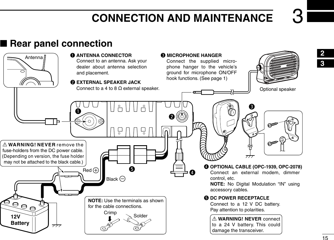
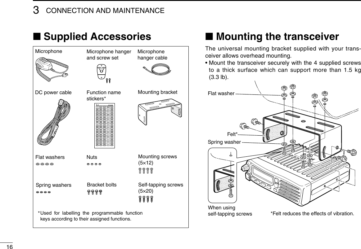
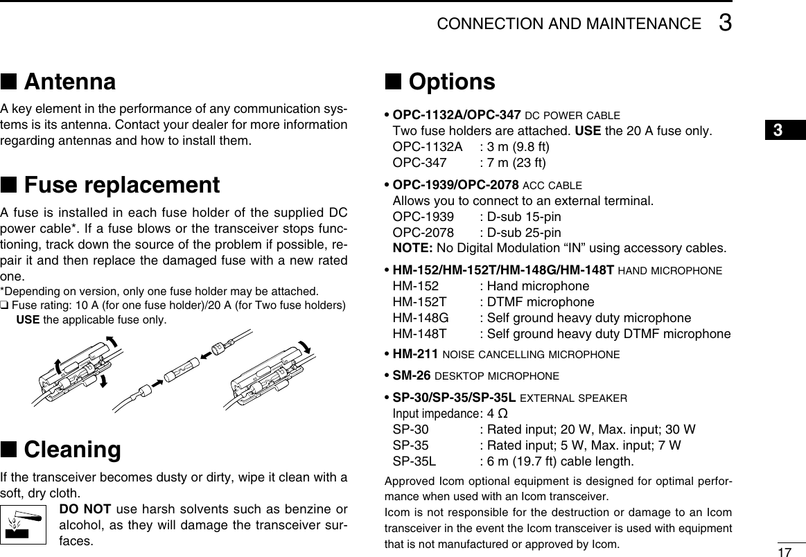
![11PANEL DESCRIPTION12345678910111213141516q wtSpeakerFunction display (p. 2)re■ Front panelq AF VOLUME CONTROL KNOB [VOL] Rotate the knob to adjust the audio output level. • Minimum audio level is pre-programmed. (p. 12)w UP/DOWN KEYS [CH Up]/[CH Down] Push to select an operating channel, etc. * The desired function can be assigned by your dealer. (p. 3)e POWER KEY [ ] Push to turn the power ON or OFF. • The following optional functions are available at power ON: - Automatic scan start - Password promptr DEALER-PROGRAMMABLE KEYS Required functions can be independently programmed by your dealer. (p. 3)t MICROPHONE CONNECTOR Connect the supplied or optional microphone. NEVER connect non-specified microphones. The pin assign-ments may be different and may damage the transceiver.D MicrophoneThe supplied or optional microphone has a PTT switch and a hanger hook.• The following functions are available when the microphone is ON or OFF hook (depending on the preprogramming): - Automatic scan starts when you put it ON hook. - Scan is cancelled when you take it OFF hook. - Scan is paused when you take it OFF hook. - Automatically selects the Priority channel when you take it OFF hook. - Sets to the ‘Inaudible’ mode (mute state) when you put it ON hook. - Sets to the ‘Audible’ mode (unmute state) when you take it OFF hook.](https://usermanual.wiki/ICOM-orporated/333212.User-Manual-IC-F6121D/User-Guide-3854477-Page-5.png)
![31PANEL DESCRIPTION12345678910111213141516■ Programmable function keysThe following functions can be assigned to [UP], [DOWN], [P0], [P1], [P2] and [P3] programmable function keys.Consult your Icom dealer or system operator for details con-cerning your transceivers programming.CH UP AND DOWN KEYS As described in the following topics, after pushing a pro-grammed key, push [CH Up] or [CH Down] to select an op-tion, setting, etc.ZONE KEYPush this key, then select the desired zone using [CH Up]/ [CH Down]. What is “zone”?— Certain channels are grouped together and assigned to a zone, according to their intended to use. For example, ‘Staff A’ and ‘Staff B’ are assigned to a “Busi-ness” zone, and ‘John’ and ‘Cindy’ are assigned to a “Pri-vate” zone.SCAN START/STOPKEY➥ Push to start and cancel scanning operation. • When a scan is started with the Power ON Scan or Automatic scan function, push this key to cancel it. The cancelled scan resumes after the pre-programmed time period. ➥ Hold down this key for 1 second to display the scan group, then push [CH Up] or [CH Down] to select the desired one.SCAN ADD/DEL (TAG) KEY➥ Push to add the channel to, or delete it from, the current scan group. 1. Push to display the scan group, then push [CH Up] or [CH Down] to select the desired one. 2. Push to add the channel to, or delete it from, the selected scan group. 3. Hold down for 1 second to exit the scan list selection mode.➥ While a scan is paused on a non-priority channel, push this key to delete the selected channel from the scan group. Depending on the setting, the cleared channel is added to the scan group again after the scan is cancelled.](https://usermanual.wiki/ICOM-orporated/333212.User-Manual-IC-F6121D/User-Guide-3854477-Page-7.png)
![41PANEL DESCRIPTION■ Programmable function keys (Continued)PRIO A/B KEYS➥ Push to select the Priority A or Priority B channel.➥ Hold down [Prio A (Rewrite)] or [Prio B (Rewrite)] for 1 second to rewrite the operating channel as Priority A or Priority B, MR-CH 1/2/3/4 KEYSPush to directly select memory channel 1 to 4.MONI (AUDI) KEY ➥ Push to turn the CTCSS (DTCS) or 2/5-tone squelch mute ON or OFF. • Only during LMR (Land Mobile Radio) operation, push to open any squelch, or deactivate any mute functions. • Only during PMR (Private Mobile Radio) operation, push to acti-vate one or two of the following functions on each channel (de-pending on the preprogramming): - Hold down to unmute the channel (‘Audible’ mode). - Push to mute the channel (‘Inaudible’ mode). - After the communication is finished, push to send a ‘reset code’ (only 5-tone operation). NOTE: The ‘Audible’ (unmute) mode may automatically return to the ‘Inaudible’ (mute) mode, after the pre-pro-grammed time period.LIGHT KEYPush to turn ON the backlight for about 5 seconds, when the backlight function is set to “OFF” in the User Set mode.LOCK KEY➥ Hold down this key until “LOCK ON” is displayed to elec-tronically lock all programmable keys except the follow-ing: [Moni(Audi)], [Lock], [Call] (incl. Call A and Call B), [Emergency], [Surveillance], [Siren], [Lone Worker] and [Light].➥ When the Key Lock function is ON, hold down this key until “LOCK OFF” is displayed to turn it OFF. LONE WORKER KEYPush to turn the Lone Worker function ON or OFF.• If the Lone Worker function is turned ON, and no operation occurs during the pre-programmed time period, the Emergency function is automatically turned ON.HIGH/LOW KEYPush to select the transmit output power temporarily or per-manently, depending on the preprogramming.• Ask your dealer for the output power level for each selection.C.TONE CH ENT KEYPush to enter the continuous tone channel selection mode. Then, push [CH Up] or [CH Down] to change the tone fre-quency/code setting. The selected channel remains set as the continuous tone channel until another channel is desig-nated as such.](https://usermanual.wiki/ICOM-orporated/333212.User-Manual-IC-F6121D/User-Guide-3854477-Page-8.png)
![51PANEL DESCRIPTION1TONE/RAN CH SELECT KEY➥ While in analog mode, push to enter the continuous tone channel selection mode. Then push [CH Up] or [CH Down] to select a desired tone frequency/code setting. After the selection, push this key again to set it.➥ While in digital mode, push to enter the RAN channel se-lection mode. Then push [CH Up] or [CH Down] to select a desired RAN code. After the selection, push this key again to set it.➥ While in mixed (digital and analog) mode, push to enter the continuous tone channel selection mode. Then push [CH Up] or [CH Down] to select a desired tone frequency/code setting. After setting, push this key to set it. After that, the RAN channel selection mode appears. Select a desired RAN code with [CH Up] or [CH Down]. After the selection, push this key again to set it.TALK AROUND KEYPush to turn the Talk Around function ON or OFF.• The Talk Around function equalizes the transmit frequency to the receive frequency for transceiver-to-transceiver communication.WIDE/NARROW KEYPush to toggle the IF bandwidth between wide and narrow. • The wide passband width can be selected from 25.0 or 20.0 kHz using the CS-F3100D/F5120D cloning software. (PMR operation only) Ask your dealer for details.DTMF AUTODIAL KEY➥ Push to enter the DTMF channel selection mode, then push [CH Up] or [CH Down] to select the desired DTMF channel.➥ After selecting the DTMF channel, push again to transmit the selected DTMF code.RE-DIAL KEYPush to transmit the last-transmitted DTMF code.• TX memories are cleared after turning OFF the transceiver.EMERGENCY KEYHold down for a specified period to transmit an emergency call.• If you want to cancel the emergency call, hold down the key again, before transmitting it.](https://usermanual.wiki/ICOM-orporated/333212.User-Manual-IC-F6121D/User-Guide-3854477-Page-9.png)
![61PANEL DESCRIPTION■ Programmable function keys (Continued)CALL KEYSPush to transmit a 2/5-tone ID code.• Tone call transmission may be necessary before you call another station, depending on your signalling system.• [Call A] and/or [Call B] may be selectable when your system em-ploys selective ‘Individual/Group’ calls. Ask your dealer which call is assigned to each key.SURVEILLANCE KEYPush to turn the surveillance function ON or OFF.When a signal is received, or a key is pushed, while this function is turned ON, the beeps do not sound and the LCD backlight does not light.SIRENHold down for 1 second to sound the siren.This function can be used for situations other than an emer-gency alert, such as a security alarm for example.• The siren can only be stopped by turning OFF the transceiver power.TX CODE ENTER KEY (PMR operation only)Push to enter the TX code edit mode, then push [CH Up] or [CH Down] to set a desired digit. (p. 11)TX CODE CHANNEL SELECT KEY➥ Push to enter the TX code channel selection mode, then push [CH Up] or [CH Down] to set a desired channel. (p. 10)➥ While in the TX code channel selection mode, hold down this key for 1 second to enter the TX code edit mode. Then push [CH Up] or [CH Down] to set a desired digit. (p. 11)TX CODE CHANNEL UP/DOWN KEYSPush to select a TX code channel.ID-MR SELECT KEY (PMR operation only)➥ Push to recall the received ID code. • Push this key, then select the ID code using [CH Up]/ [CH Down]. • Up to 5 codes can be memorized.➥ Hold down this key for 1 second to clear the selected ID code.ENCRYPTION KEY While operating in the digital mode, push to turn the encryp-tion function ON or OFF.](https://usermanual.wiki/ICOM-orporated/333212.User-Manual-IC-F6121D/User-Guide-3854477-Page-10.png)
![71PANEL DESCRIPTION12345678910111213141516USER SET MODE KEY➥ Hold down for 1 second to enter the User Set mode. • While in the User Set mode, push this key to select an item*, and change the value or setting using [CH Up] or [CH Down]. * Selectable items may differ, depending on the preprogram-ming.➥ Hold down this key for 1 second again to exit the User Set mode.HOOK SCANWhen the Hook Scan function is pre-programmed, push this key to temporarily disable the function. Push this key again to enable the function.Ext. CH Sel Mode KEYPush to turn the Ext. CH Select function ON or OFF. When the function is turned ON, memory channels can be selected with only and external input. When the function is turned OFF, memory channels can be selected by pushing [CH Up] or [CH Down], and cannot be externally controlled. • This function is available when the external unit, such as a dimmer control is connected to the transceiver with an optional OPC-1939 or OPC-2078 cable (p. 17).• Ask your dealer for more details on external input operation.POWER OFF EMERGENCYWhile holding down this key, turn OFF the transceiver to activate the Power OFF Emergency function. This function makes the transceiver transmit emergency calls, even though it appears to be powered OFF. (p. 14)](https://usermanual.wiki/ICOM-orporated/333212.User-Manual-IC-F6121D/User-Guide-3854477-Page-11.png)
![82BASIC OPERATION■ Turning ON the powerq Push [ ] to turn ON the power.w If the transceiver is programmed for a start up password, input the digit codes as directed by your dealer. • The keys shown below can be used for password input: The transceiver detects numbers in the same block as identical. Therefore “01234” and “56789” are the same.e If the “PASSWORD” indication does not clear after input-ting 6 digits, the input code number may be incorrect. Turn OFF the power and re-enter your password.■ Channel selectionThere are several methods to select channels, and they may differ, depending on your system set up.NON-ZONE TYPE:To select the desired operating channel:• Push [CH Up] or [CH Down].• Push one of [MR-CH 1] to [MR-CH 4].ZONE TYPE:To select the desired operating channel:Push [Zone], then push [CH Up] or [CH Down].AUTOMATIC SCAN TYPE:Channel setting is not necessary for this type. When turning ON the power, the transceiver automatically starts scanning. Scanning stops when a signal is detected.KEYNUMBER 0549382716](https://usermanual.wiki/ICOM-orporated/333212.User-Manual-IC-F6121D/User-Guide-3854477-Page-12.png)
![92BASIC OPERATION12345678910111213141516■ Call procedureWhen your system employs tone signaling (excluding CTCSS and DTCS), a call procedure may be necessary prior to voice transmission. The tone signalling employed may be a selective calling system which allows you to call only specific station(s), and prevents unwanted stations from contacting you.q Select the desired TX code channel or 2/5-tone code, ac-cording to your System Operator’s instructions. • This may not be necessary, depending on the preprogram-ming. • Refer to pages 10 and 11 for selection.w Push [Call] (assigned to one of the dealer programmable keys).e After transmitting, the remainder of your communication can be carried out in the normal fashion.Selective calling Non-selective calling■ Receiving and transmittingReceiving:q Hold down [] for 1 second to turn ON the power.w Push [CH Up] or [CH Down] to select a channel.e When receiving a call, rotate [VOL] to adjust the audio out-put level to a comfortable listening level.NOTE: Depending on the preprogramming, the transceiver automatically transmits the microphone audio for the specified time period*, when a matched RX code signal is received.• HM-148G or HM-152 hand microphone is required.* Depending on the preprogramming. Ask your dealer for details.Transmitting:Wait for the channel to become clear to avoid interference.q Take the microphone OFF hook. • The ‘Audible’ mode is selected. • A priority channel may be automatically selected.w Wait for the channel to become clear. • The channel is busy when the BUSY icon appears on the LCD.e While holding down [PTT], speak into the microphone at your normal voice level.r Release [PTT] to return to receive. IMPORTANT: To maximize the readability of your signal; 1. Pause briefly after pushing [PTT]. 2. Hold the microphone 5 to 10 cm (2 to 4 inches) from your mouth, then speak into the microphone at a normal voice level.](https://usermanual.wiki/ICOM-orporated/333212.User-Manual-IC-F6121D/User-Guide-3854477-Page-13.png)
![102BASIC OPERATION■ Receiving and transmitting (Continued)D Transmitting notes• Transmit inhibit function The transceiver has several inhibit functions which restrict transmission under the following conditions: - The channel is in the ‘Inaudible’ (mute) mode; “ ” (Audible icon) does not appear. - The channel is busy. However, depending on the prepro-grammed settings, you can transmit when the call includes an unmatching (or matching) CTCSS (DTCS), RAN code, or Individual or Talkgroup ID. - The selected channel is a ‘receive only’ channel.• Time-out timer If continuous transmission exceeds the pre-programmed time-out timer limit, the transmission is cut off.• Penalty timer After the transmission is cut off by the time-out timer, trans-mission is further inhibited for the pre-programmed penalty timer period.• PTTID call The transceiver automatically sends the 5-tone, DTMF, BIIS or digital ANI ID code when [PTT] is pushed (at the begin-ning of the transmission), and/or when it is released (at the end of transmission), depending on the preprogramming. A PTTID call also be made with the MDC 1200 signaling system.D TX code channel selectionIf the transceiver has a key assigned to [TX Code CH Select], the display can be toggled between the operating channel number (or name) and TX code channel number (or name). When the TX code channel number (or name) is displayed, [CH Up] or [CH Down] selects the TX code channel.USING [TX CODE CH SELECT] KEY:q Push [TX Code CH Select]— a TX code channel number (or name) appears.w Push [CH Up] or [CH Down] to select the desired TX code channel.e After selecting, push [TX Code CH Select] to set. • Return to the stand-by mode.r Push [Call] to transmit the selected TX code.USING [TX CODE CH UP]/[TX CODE CH DOWN] KEY:If the transceiver has a key assigned to [TX Code CH Up] or [TX Code CH Down], the programmed TX code channel can be directly selected when pushed.](https://usermanual.wiki/ICOM-orporated/333212.User-Manual-IC-F6121D/User-Guide-3854477-Page-14.png)
![112BASIC OPERATION12345678910111213141516D TX code number edit (PMR operation only)If the transceiver has a key assigned to [TX Code CH Select] or [TX Code Enter], TX code contents can be edited within the allowable digits.USING [TX CODE CH SELECT] KEY:q Push [TX Code CH Select] to enter the TX code channel selection mode. • Select the desired channel before entering the TX code channel selection mode, if necessary.w Hold down [TX Code CH Select] for 1 second to enter the TX code edit mode. • The digit to be edited blinks.e Push [TX Code CH Select] to select the desired digit to be edited.r Push [CH Up] or [CH Down] to select the desired digit.t Push [TX Code CH Select] to set. The digit to the right will automatically blink.y Repeat r and t to edit all allowable digits.u After editing, push [TX Code CH Select] to set. • Return to the stand-by mode.i Push [Call] to transmit.USING [TX CODE ENTER] KEY:q Push [TX Code Enter] to enter the TX code edit mode. • The digit to be edited blinks.w Push [TX Code Enter] to select the desired digit to be ed-ited.e Push [CH Up] or [CH Down] to select the desired digit.r Push [TX Code Enter] to set. The digit to the right will au-tomatically blink.t Repeat e and r to edit all allowable digits.y After editing, push [TX Code Enter] to set. • Return to the stand-by mode.u Push [Call] to transmit.D DTMF transmissionIf the transceiver has a key assigned to [DTMF Autodial], the automatic DTMF transmission function is available. Up to 8 DTMF channels are selectable.q Push [DTMF Autodial]— a DTMF channel appears.w Push [CH Up] or [CH Down] to select the desired DTMF channel.e Push [DTMF Autodial] to transmit the DTMF code.](https://usermanual.wiki/ICOM-orporated/333212.User-Manual-IC-F6121D/User-Guide-3854477-Page-15.png)
![122BASIC OPERATION■ User Set modeThe User Set mode allows you to set seldom-changed set-tings, and you can “customize” the transceiver operation to suit your preferences and operating style.Entering the User Set mode:q Hold down [SET] for 1 second to enter the User Set mode.w Push [SET] several times to select the appropriate item. Then push [CH Up] or [CH Down] to set the desired level or option. • In the User set mode, the selectable items are preset by your dealer. The presetable Set mode items are Backlight, Beep ON/OFF, Beep Level, Ringer Level, SQL Level, AF Min Level, Mic Gain, Battery Voltage, Horn, Signal Moni, Lone Worker and System Info.e Hold down [SET] for 1 second again to exit the User Set mode.■ Encryption functionThe encryption function provides private communication be-tween stations while operating in the digital mode.q Push [Encryption] to turn ON the encryption function. • “ ” (Encryption icon) appears.w Push [Encryption] again to turn OFF the encryption func-tion. • “ ” disappears.■ Stun functionThe dispatcher can send a 2/5-tone signal that will stun, kill or revive your transceiver. When the Stun ID is received, a beep sounds*, and the trans-ceiver becomes unusable. Receiving a Revive command or entering password* (p. 8) is necessary to operate the trans-ceiver again in this case.When the Kill ID is received, a beep sounds*, and the trans-ceiver becomes unusable (the transceiver switches to the cloning required condition). Cloning the transceiver is neces-sary to operate the transceiver again in this case.* Depending on the preprogramming. Ask your dealer for de-tails. See the operating guide for details of the Stun function with the MDC and Digital system operations. Ask your dealer for details.](https://usermanual.wiki/ICOM-orporated/333212.User-Manual-IC-F6121D/User-Guide-3854477-Page-16.png)
![132BASIC OPERATION2■ Emergency transmissionWhen [Emergency] is held down for the specified time pe-riod*, the emergency signal is transmitted on the specified emergency channel once or repeatedly.When no emergency channel is specified, the call is transmit-ted on the operating channel.The repeat emergency signal is automatically transmitted until you turn OFF the power.Depending on the preprogramming, receiving a matching 5-tone code cancels the transmission.If you want to cancel the Emergency function, hold down [Emergency] for the pre-programmed time period again be-fore transmitting the call.If your transceiver is programmed for Silent operation, you can transmit emergency calls without the beep sounding and the LCD indication change. IMPORTANT: It is recommended to set an emergency channel individually to provide the certain emergency call operation.D NOTESDepending on the preprogramming, the following functions are automatically activated. Ask your dealer for details.• Auto TX functionAfter the emergency call transmission, audio from the micro-phone is automatically transmitted for a specified time pe-riod.*• The HM-148G or HM-152 hand microphone is required.• Auto RX functionAfter the emergency call transmission, the transceiver stands by in the audible mode for the specified time period.** Depending on the preprogramming. Ask your dealer for de-tails.](https://usermanual.wiki/ICOM-orporated/333212.User-Manual-IC-F6121D/User-Guide-3854477-Page-17.png)
![142BASIC OPERATION■ Power OFF Emergency functionWhen the transceiver has a key assigned to Power OFF Emergency, you can use the function.This function makes the transceiver transmit emergency calls, even though it appears to be powered OFF.To activate the Power OFF Emergency function, turn the power OFF while holding down [Power OFF Emergency].When the function is activated, any key operation, the ON/OFF Hook and Lone Worker functions become invalid. The beep, display and speaker are turned OFF as well.On the other hand, the transceiver can transmit emergency calls according to the pre-programmed emergency settings.Depending on the pre-programmed settings, the Remote Monitor function can also be used (digital operation only).To cancel the Power OFF Emergency function and restore the transceiver, turn the power ON.■ Priority A channel selectionWhen one of the following operations is performed, the trans-ceiver automatically selects the Priority A channel.• Turning ON the power The Priority A channel is selected each time the transceiver power is turned ON.• Auto Reset The Priority A channel is selected when the Auto Reset timer ends.• OFF hook The Priority A channel is selected when you take the micro-phone OFF hook.](https://usermanual.wiki/ICOM-orporated/333212.User-Manual-IC-F6121D/User-Guide-3854477-Page-18.png)