ICOM orporated 333212 UHF Digital Transceiver User Manual IC F5020 F6020 series Instruction Manual
ICOM Incorporated UHF Digital Transceiver IC F5020 F6020 series Instruction Manual
Contents
- 1. User_Manual_IC-F6121D
- 2. User_Manual_IC-F6220D
User_Manual_IC-F6220D
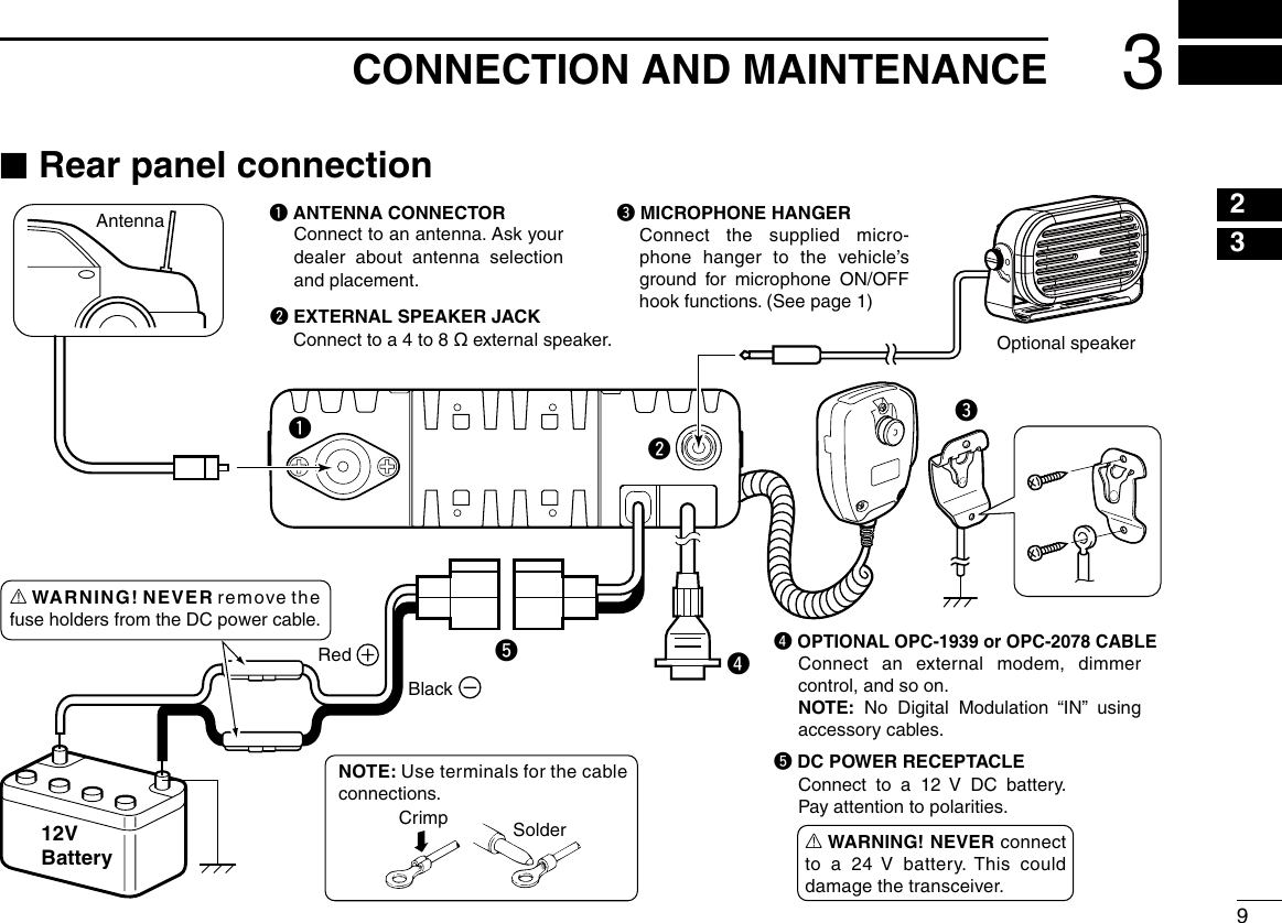
![11PANEL DESCRIPTION12345678910111213141516q wtSpeakerFunction display (p. 2)re ■Front panelq AF VOLUME CONTROL KNOB [VOL] Rotate the knob to adjust the audio output level. • Minimum audio level is preprogrammed. (p. 8)w UP/DOWN KEYS [UP]/[DOWN] Push to select an operating channel and so on. * The desired function can be assigned by your dealer. (p. 3)e POWER KEY [ ] Push to turn the power ON or OFF. • The following optional functions are available at power ON: - Automatic scan start - Password promptr DEALER-PROGRAMMABLE KEYS Required functions can be independently programmed by your dealer. (p. 3)t MICROPHONE CONNECTOR Connect the supplied or optional microphone. See page 10 for detail of the PTT switch and a hanger hook operations. NEVER connect non-specified microphones. The pin assignments may be different and may damage the transceiver.](https://usermanual.wiki/ICOM-orporated/333212.User-Manual-IC-F6220D/User-Guide-3854478-Page-5.png)
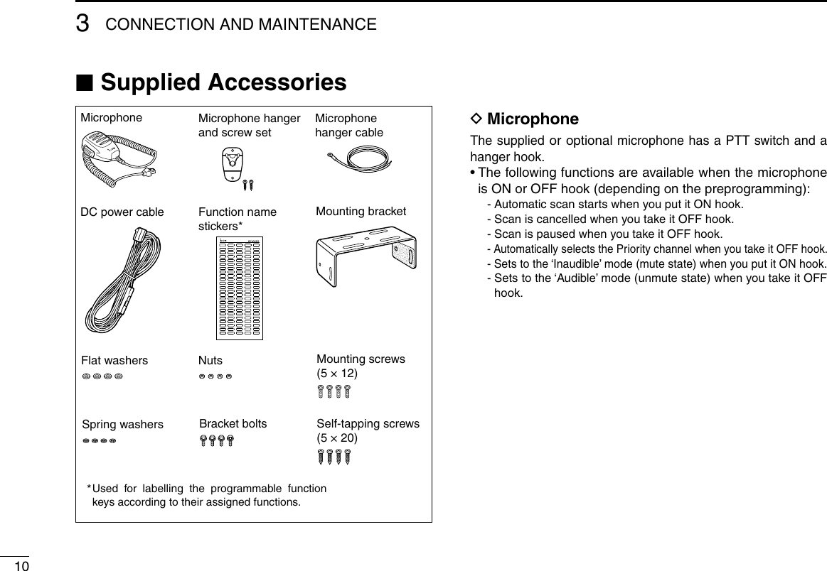
![21PANEL DESCRIPTION ■Function displayq w e r t y u i o!0q TRANSMIT ICON Appears while transmitting a signal.w BUSY ICON Appears while the channel is busy (receiving).e SIGNAL STRENGTH ICON Shows the relative receive signal strength level.Weak Receive Signal level Strong About “ ” icon for the Trunking mode ➥ Disappears while in the no service area. ➥ Blinks while registering to the repeater. ➥ Appears when the registration is completed.r LOW POWER ICON Appears when low output power is selected.t AUDIBLE ICON ➥ In the analog mode, appears when the CTCSS (DTCS) squelch mute is released while holding down [Monitor]. ➥ In the digital mode, appears while holding down [Moni-tor].y GPS ICON Appears when the GPS receiver acquires the received GPS signal from a satellite.u ENCRYPTION ICON In the digital mode, appears when the encryption function is activated.i BELL ICON In the digital mode, appears/blinks when a SDM (Short Data Message), Status Call or Call Alert is received, de-pending on the preprogramming.o SCAN ICON ➥ Blinks during a scan. ➥ Appears when a scan channel is selected.!0 ALPHANUMERIC DISPLAY Displays an operating channel number, channel name, User Set mode contents, and so on.](https://usermanual.wiki/ICOM-orporated/333212.User-Manual-IC-F6220D/User-Guide-3854478-Page-6.png)
![31PANEL DESCRIPTION12345678910111213141516 ■Programmable function keysThe following functions can be assigned to [UP], [DOWN], [P0], [P1], [P2] and [P3] programmable function keys.Consult your Icom dealer or system operator for details con-cerning your transceivers programming.NOTE: The function keys for the digital mode are described in the operating guide.CH UP AND DOWNAs described in the following topics, after pushing a pro-grammed key, push [CH Up] or [CH Down] to select an op-tion, setting, and so on.ZONEPush this key, then select the desired zone using [CH Up]/ [CH Down]. What is “zone”?— Certain channels are grouped togeth-er and assigned to a zone, according to their intended to use. For example, ‘Staff A’ and ‘Staff B’ are assigned to a “Business” zone, and ‘John’ and ‘Cindy’ are assigned to a “Private” zone.SCAN START/STOP ➥Push to start and cancel a scan. • When a scan is started with the Power ON Scan or Automatic scan function, push this key to cancel it. The cancelled scan re-sumes after the preprogrammed time period. ➥ Hold down this key for 1 second to display the scan group, then push [CH Up] or [CH Down] to select the desired one.SCAN ADD/DEL (TAG) ➥ Push to add the channel to, or delete it from, the current scan group. 1. Hold down to display the scan group, then push [CH Up] or [CH Down] to select the desired one. 2. Push to add the channel to, or delete it from, the selected scan group. 3. Hold down for 1 second to exit the scan list selection mode. ➥ While a scan is paused on a non-priority channel, push this key to delete the selected channel from the scan group. Depending on the setting, the cleared channel is added to the scan group again after the scan is cancelled.](https://usermanual.wiki/ICOM-orporated/333212.User-Manual-IC-F6220D/User-Guide-3854478-Page-7.png)
![41PANEL DESCRIPTION ■Programmable function keys (Continued)PRIORITY A CHANNEL, PRIORITY B CHANNELPush to select the Priority A or Priority B channel.PRIORITY A CHANNEL (REWRITE),PRIORITY B CHANNEL (REWRITE) ➥Push to select the Priority A or Priority B channel. ➥ Hold down [Prio A (Rewrite)] or [Prio B (Rewrite)] for 1 second to assign the operating channel to Priority A or Priority B channel, respectively.MEMORY CHANNELS 1, 2, 3, 4Push to directly select memory channel 1, 2, 3 or 4, if pro-grammed.Consult your dealer for details.MONITOR Push to turn the CTCSS (DTCS) squelch mute ON or OFF. LIGHTPush to turn ON the backlight for about 5 seconds, when the backlight function is set to “OFF” in the User Set mode.HIGH/LOWPush to select the transmit output power temporarily or per-manently, depending on the preprogramming.• Ask your dealer for the output power level for each selection.LOCK ➥ Hold down this key until “LOCK ON” is displayed to elec-tronically lock all programmable keys except the following: [Moni], [Lock], [Emergency]*, [Power OFF Emergency]*, [Surveillance], [Siren], [Lone Worker]*, [Light] and [Shift]. * For digital operation. See the operating guide for details ➥ To turn OFF the Key Lock function, hold down this key until “LOCK OFF” is displayed.TALK AROUNDPush to turn the Talk Around function ON or OFF.• The Talk Around function equalizes the transmit frequency to the receive frequency for transceiver-to-transceiver communication.WIDE/NARROWPush to toggle the IF bandwidth between wide and narrow. SURVEILLANCEPush to turn the surveillance function ON or OFF.When this function is turned ON and a signal is received, the beep is not heard and the LED does not light, even if a key is pushed.SIRENHold down for 1 second to sound the siren.This function can be used for situations other than an emer-gency alert, such as a security alarm for example.• The siren can only be stopped by turning OFF the transceiver power.](https://usermanual.wiki/ICOM-orporated/333212.User-Manual-IC-F6220D/User-Guide-3854478-Page-8.png)
![51PANEL DESCRIPTION12345678910111213141516HOOK SCANWhen the Hook Scan function is preprogrammed, push this key to temporarily disable the function. Push this key again to enable the function.USER SET MODE ➥ Hold down for 1 second to enter the User Set mode. • While in the User Set mode, push this key to select an item*, and change the value or setting using [CH Up] or [CH Down]. * Selectable items may differ, depending on the preprogram-ming. ➥ Hold down this key for 1 second again to exit the User Set mode.EXT. CH SEL MODEPush to turn the Ext. CH Select function ON or OFF. When the function is turned ON, memory channels can be selected with only an external input.When the function is turned OFF, memory channels can be selected by pushing [CH Up] or [CH Down], and cannot be externally controlled. • This function is usable when an external unit, such as a dimmer control is connected to the transceiver with an optional OPC-1939 or OPC-2078 cable (p. 12).• Ask your dealer for more details on external input operation.ANNOUNCEPush to turn the Channel Announce function ON or OFF.When this function is turned ON, the transceiver announces the channel number when it is selected.RESET ➥Push to return to the normal operating mode. ➥ While in the audible mode, push to return to the inaudible mode.NOTE: See the operating guide for the [Reset] key opera-tions in the digital mode.GPS DISPLAYPush to switch the display mode between stand-by and GPS position data.SHIFTPush to switch the Normal mode key functions and the Shift mode key functions.• When the Shift mode is selected, the display briefly shows “SHIFT ON.” When the Normal mode is selected, the display briefly shows “SHIFT OFF.”](https://usermanual.wiki/ICOM-orporated/333212.User-Manual-IC-F6220D/User-Guide-3854478-Page-9.png)
![62BASIC OPERATION ■Turning ON the power qPush [ ] to turn ON the power. w If the transceiver is programmed for a start up password, input the digit codes that were set by your dealer. • The keys shown below can be used for password input: The transceiver detects numbers in the same block as identical. Therefore “01234” and “56789” are the same.KEYNUMBER 0549382716 e If the “PASSWORD” indication does not clear after input-ting 6 digits, the input code number may be incorrect. Turn OFF the power and re-enter your password. ■Channel selectionThere are several ways to select channels, and they may dif-fer, depending on your system set up.NON-ZONE TYPE:To select the desired operating channel: ➥Push [CH Up] or [CH Down]. ➥Push one of [MR-CH 1] to [MR-CH 4].ZONE TYPE:To select the desired operating channel: ➥Push [Zone], then push [CH Up] or [CH Down].VOTING OPERATION:The transceiver automatically starts scanning when a zone, specified for the voting operation, is selected.The voting scan detects the S-meter of the repeater and au-tomatically selects the strongest station.AUTOMATIC SCAN TYPE:Channel setting is not necessary for this type. When turning ON the power, the transceiver automatically starts scanning. Scanning stops when a signal is detected.](https://usermanual.wiki/ICOM-orporated/333212.User-Manual-IC-F6220D/User-Guide-3854478-Page-10.png)
![72BASIC OPERATION12345678910111213141516 ■Receiving and transmittingReceiving: qHold down [] for 1 second to turn ON the power. w Push [CH Up] or [CH Down] to select a channel. e When receiving a call, rotate [VOL] to adjust the audio out-put level to a comfortable listening level.Transmitting:Wait for the channel to become clear to avoid interference. q Take the microphone OFF hook. • The ‘Audible’ mode is selected. • A priority channel may be automatically selected. wWait for the channel to become clear. • The channel is busy when the BUSY icon appears on the LCD. e While holding down [PTT], speak into the microphone at your normal voice level. rRelease [PTT] to return to receive. IMPORTANT: To maximize the readability of your signal; 1. Pause briefly after pushing [PTT]. 2. Hold the microphone 5 to 10 cm (2 to 4 inches) from your mouth, then speak into the microphone at a normal voice level. DTransmitting notes• Transmit inhibit function The transceiver has several inhibit functions which restrict transmission under the following conditions: - The channel is busy. However, depending on the preprogrammed settings, you can transmit when the call includes an unmatching (or matching) CTCSS (DTCS), RAN code*, or Individual or Talk-group ID*. * Digital operation only - The selected channel is a ‘receive only’ channel.• Time-out timer If continuous transmission exceeds the preprogrammed time-out timer limit, the transmission is cut off.• Penalty timer After the transmission is cut off by the time-out timer, trans-mission is further inhibited for the preprogrammed penalty timer period.](https://usermanual.wiki/ICOM-orporated/333212.User-Manual-IC-F6220D/User-Guide-3854478-Page-11.png)
![82BASIC OPERATION ■User Set modeThe User Set mode allows you to set seldom-changed set-tings. If the transceiver has [User Set Mode] assigned to it, you can “customize” the transceiver operation to suit your preferences and operating style.Entering the User Set mode: q Hold down [User Set Mode] for 1 second to enter the User Set mode. w Push [User Set Mode] several times to select the appro-priate item. Then push [CH Up] or [CH Down] to set the desired level/condition. • Selectable Set mode items are Backlight, Beep ON/OFF, Beep Level, Ringer Level, SQL Level, AF Min Level, Mic Gain, Horn, Battery Voltage, Signal Moni, Lone Worker and Sys-tem Info. e Hold down [User Set Mode] for 1 second again to exit the User Set mode. ■Priority A channel selectionWhen one of the following operations is performed, the trans-ceiver automatically selects the Priority A channel.• Turning ON the power The Priority A channel is selected each time the transceiv-er power is turned ON.• Auto Reset The Priority A channel is selected when the Auto Reset timer ends.• OFF hook The Priority A channel is selected when you take the mi-crophone OFF hook.](https://usermanual.wiki/ICOM-orporated/333212.User-Manual-IC-F6220D/User-Guide-3854478-Page-12.png)