ICOM orporated 333502 UHF Mobile Transceiver User Manual IC F5020 F6020 series Instruction Manual
ICOM Incorporated UHF Mobile Transceiver IC F5020 F6020 series Instruction Manual
UserManual.wiki
>
ICOM orporated
>
333502 User Manual
User Manual
Navigation menu
Upload a User Manual
Namespaces
Wiki Guide
HTML
PDF
Info
Views
User Manual
Discussion / Help
Navigation
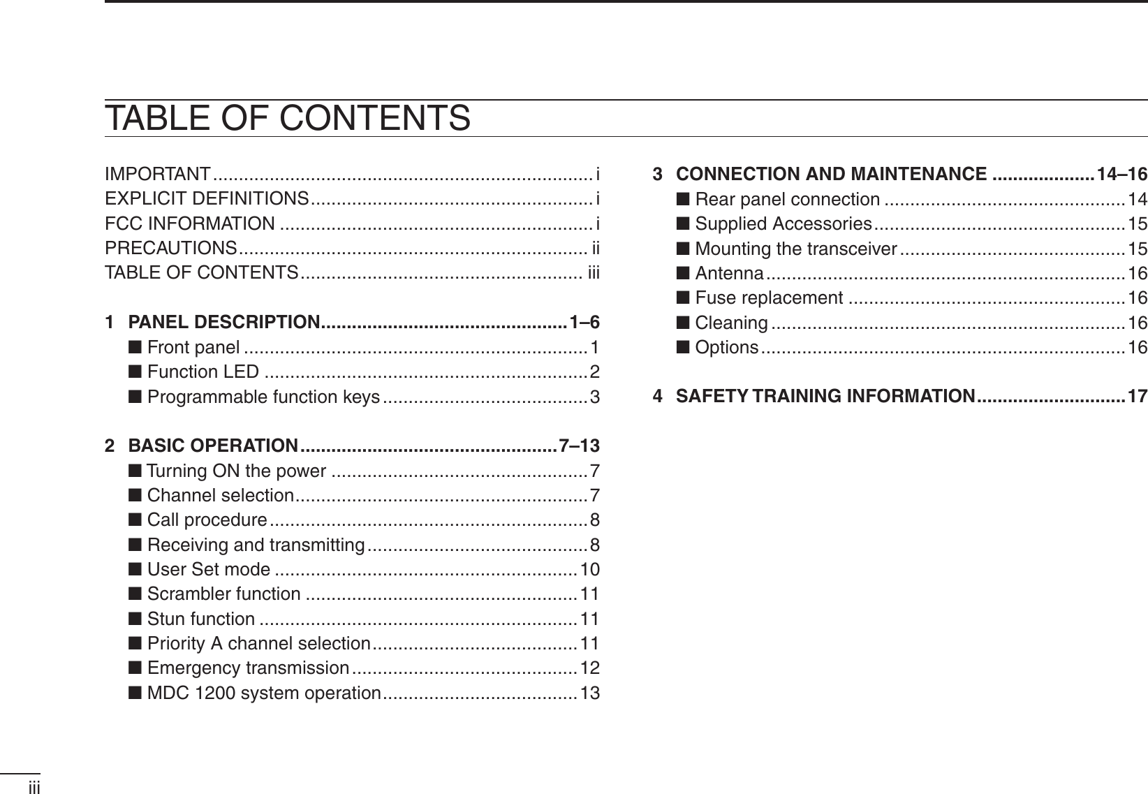
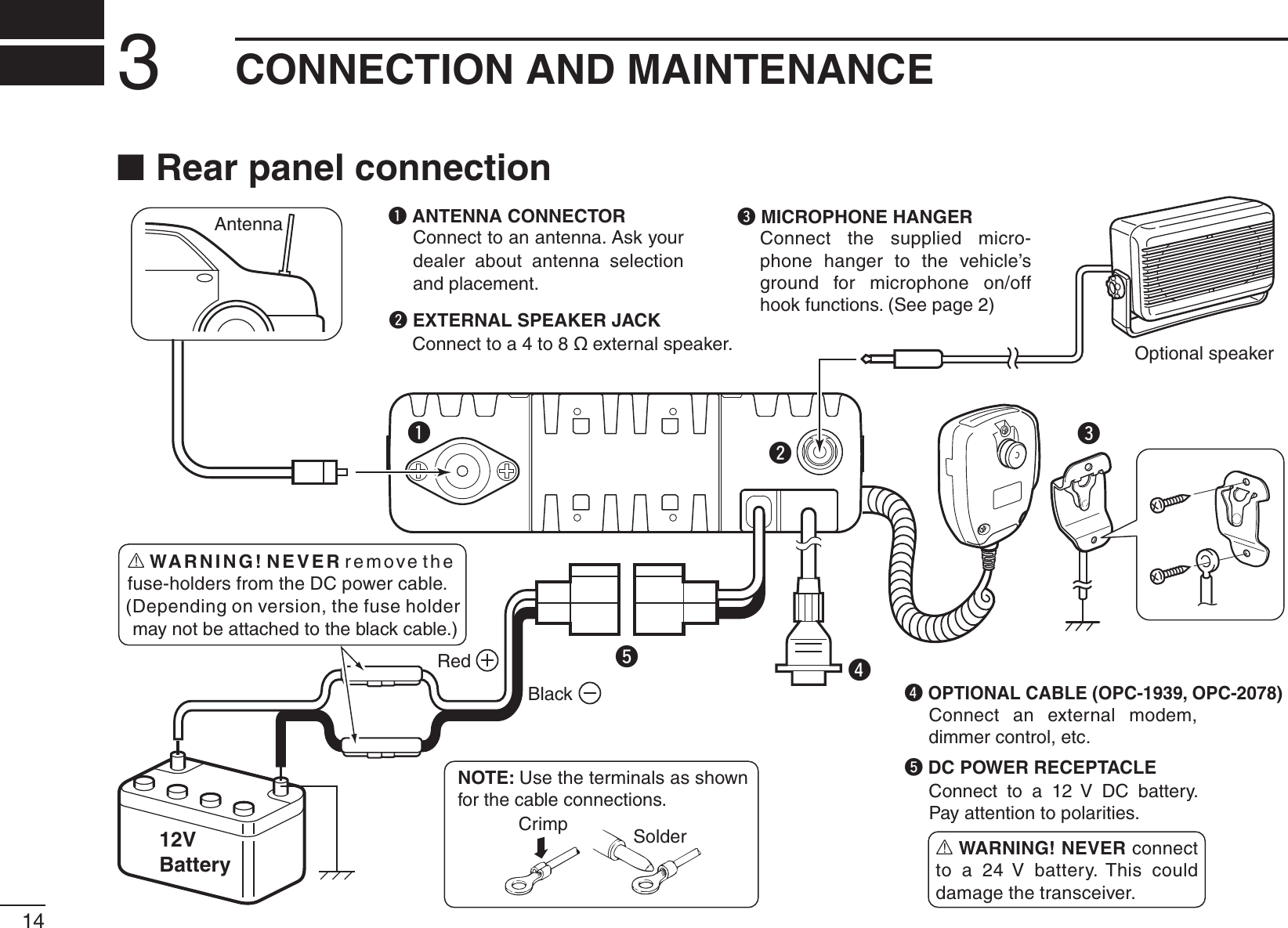
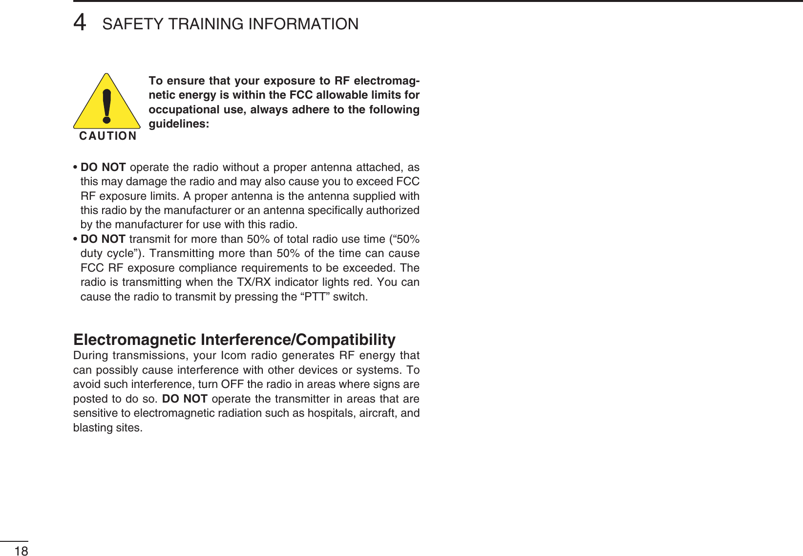
![11PANEL DESCRIPTION12345678910111213141516TX/RX1234P0 P1 P2 P3qeSpeakerFunction LED (p. 2)rwN Front panelq AF VOLUME CONTROL KNOB [VOL] Rotate the knob to adjust the audio output level. s-INIMUMAUDIOLEVELISPRESETPw MICROPHONE CONNECTOR Connect the supplied or optional microphone. NEVER connect non-specified microphones. The pin assignments may be different and the transceiver may be damaged.e DEALER-PROGRAMMABLE KEYS Desired functions can be independently programmed by your dealer. (p. 3)r POWER KEY [ ]Push to turn the power ON or OFF. s4HEFOLLOWINGOPTIONALFUNCTIONSAREAVAILABLEATPOWER/. - Automatic scan start - Password prompt - User Set mode](https://usermanual.wiki/ICOM-orporated/333502/User-Guide-1394343-Page-5.png)
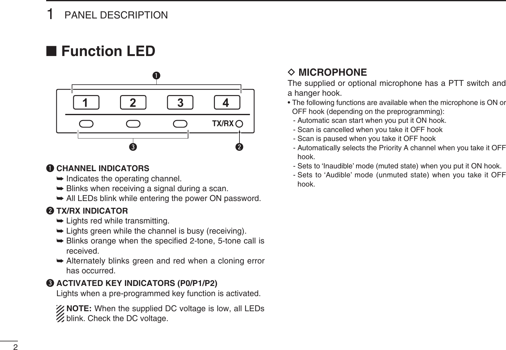
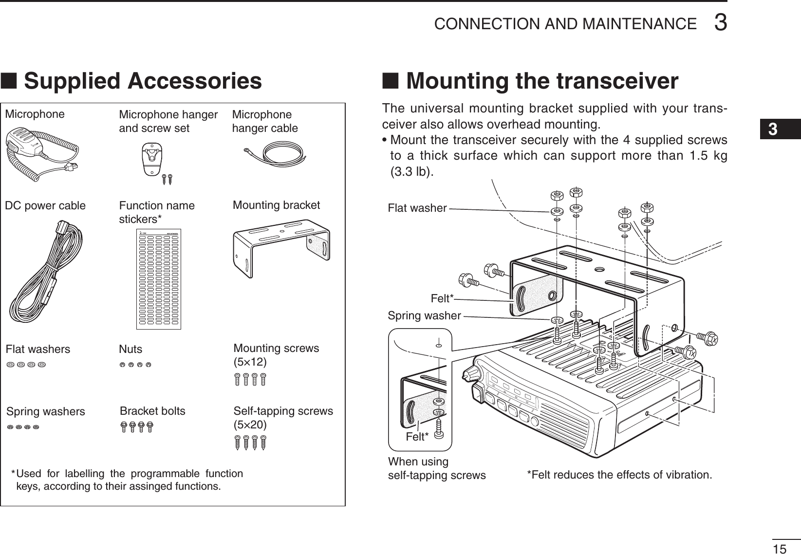
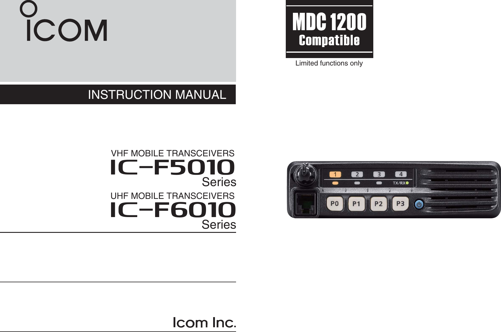
![31PANEL DESCRIPTION12345678910111213141516N Programmable function keysThe following functions can be assigned to [P0], [P1], [P2] and [P3] programmable function keys.Consult your Icom dealer or system operator for details con-cerning your transceivers programming.CH UP AND DOWN KEYS Push to select an operating channel.SCAN A START/STOP KEYPush to start or cancel a scan.SCAN B START/STOP KEYPush to start or cancel a scan.When a scan started with the Power ON Scan or by pushing THIS KEY PUSH TO CANCEL IT )F THE SCAN IS CANCELLED EXCEPTby pushing this key, the cancelled scan resumes after the specified time period.SCAN ADD/DEL (TAG) KEYWhile scan is paused by a detected signal, on a channel other than a priority channel, push this key to clear the chan-nel from the scan list. Depending on the preprogramming, the cleared channel is added to the scan list again after the scan is cancelled.PRIO A/B KEYS± Push to select Priority Channel A or B.± To rewrite the operating channel as Priority A or Priority B, hold down [Prio A (Rewrite)] or [Prio B (Rewrite)] for 1second.MR-CH 1/2/3/4 KEYSPush to directly select memory channels 1 to 4.MONI (AUDI) KEY±0USHTOTURNTHE#4#33$4#3ORTONESQUELCH-UTEON or OFF. s/NLYDURING,-2OPERATIONHOLDDOWNTOOPENANYSQUELCHfunctions, or deactivate any mute functions. s/NLYDURING0-2OPERATIONPUSHTOACTIVATEONEORTWOOFTHEfollowing functions* on each channel. - Hold down to unmute the channel (Audible mode). - Push to mute the channel (Inaudible mode). - Push to send a ‘reset code’ after the communication is fin-ished. *Ask your dealer for details. ./4% After a specified period, the un-muted state (‘Au-dible’ mode) may automatically return to the muted state (‘Inaudible’ mode), depending on the preprogramming.± Hold down this key for 1 second to cancel a scan, depend-ing on the preprogramming.](https://usermanual.wiki/ICOM-orporated/333502/User-Guide-1394343-Page-7.png)
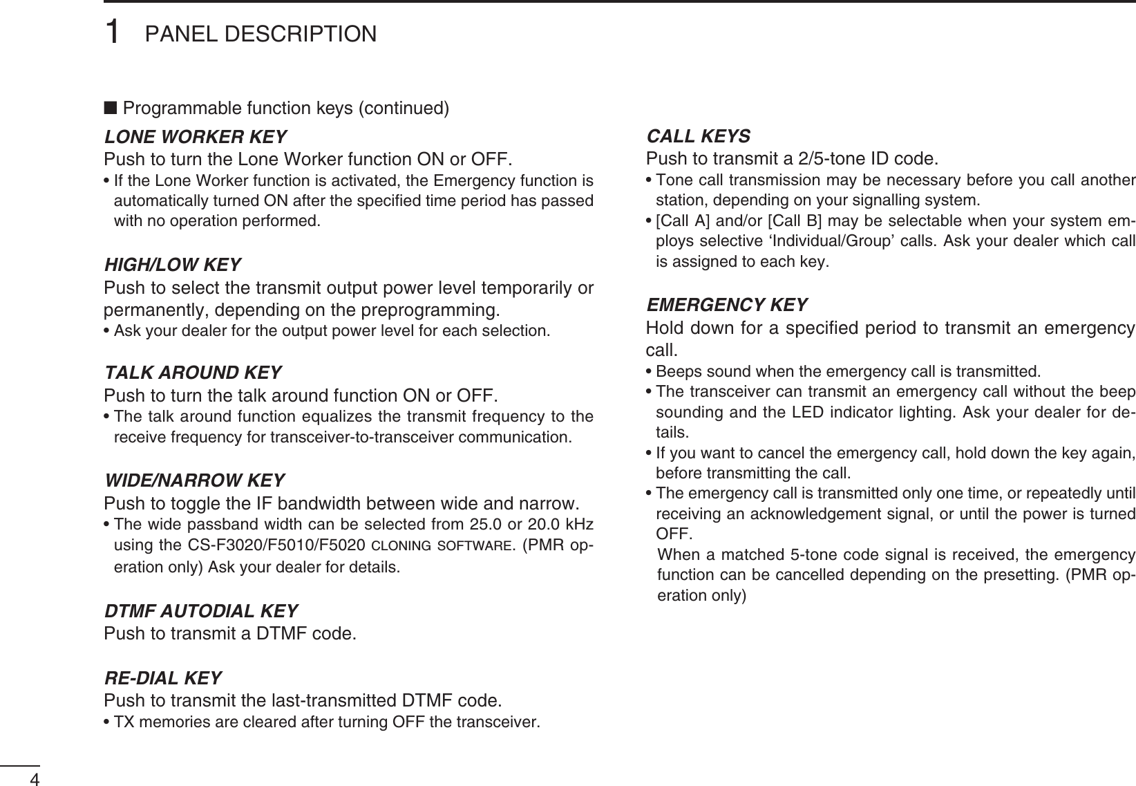
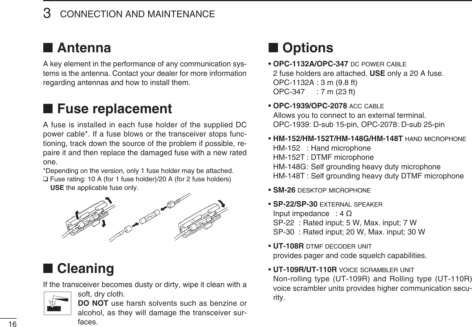
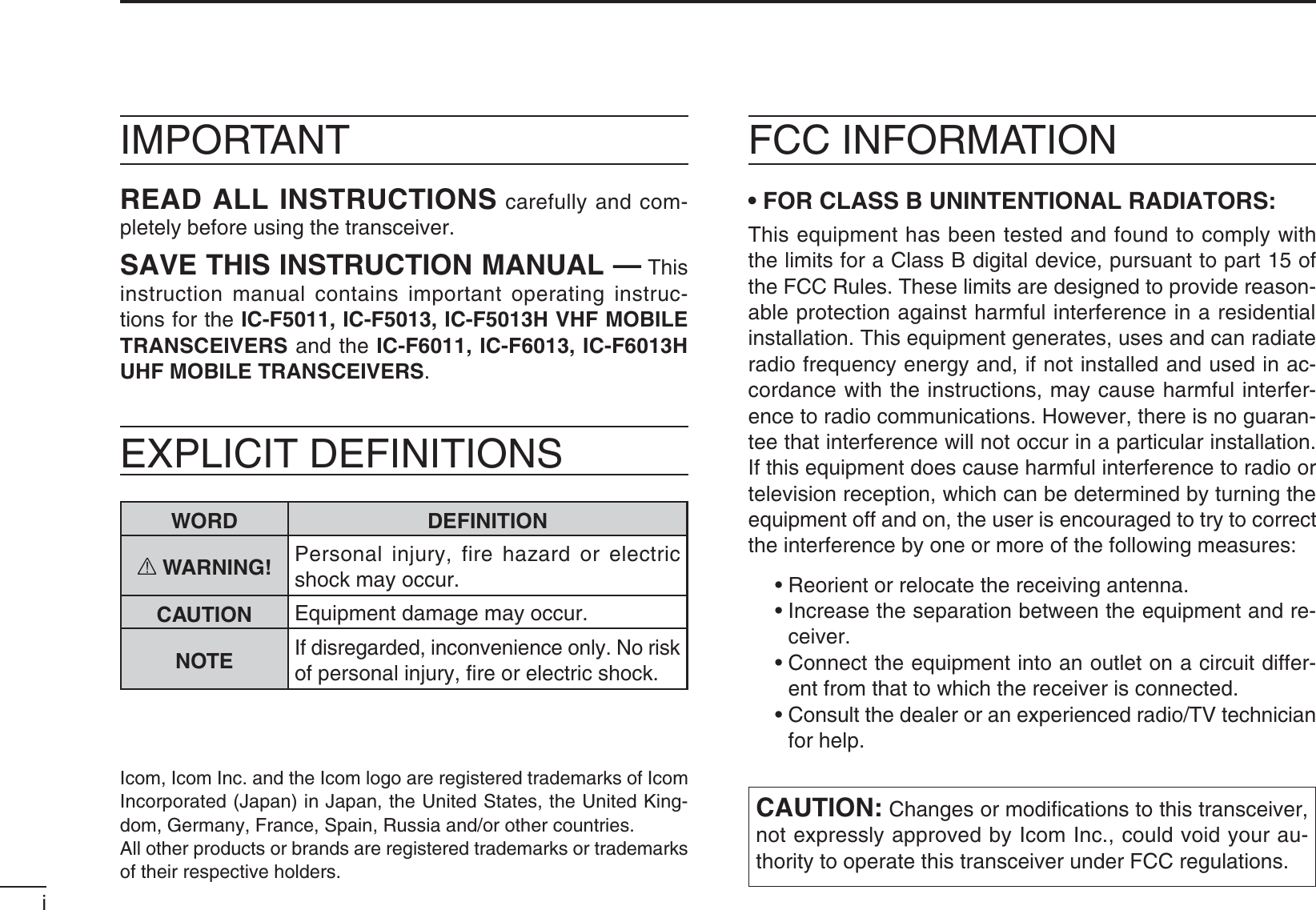
![72BASIC OPERATION12345678910111213141516N Turning ON the powerq Push [ ] to turn ON the power.w If the transceiver is programmed for a start up password, input the digit codes as directed by your dealer. s4HEKEYSSHOWNBELOWCANBEUSEDFORPASSWORDINPUT The transceiver detects numbers in the same block as identical. Therefore “01234” and “56789” are the same.e If all channel indicator LEDs still blink after inputting 4 dig-its, the input code number may be incorrect. Turn OFF the power and re-enter your password.N Channel selectionThere are several methods to select channels, and they may differ, according to your system set up.Push [CH Up] or [CH Down] to sequentially select the desired operating channel, or push one of the [MR-CH 1] to [MR-CH 4] keys to select a channel directly.AUTOMATIC SCAN TYPE:Channel setting is not necessary for this type. When turn-ing ON power, the transceiver automatically starts scanning. Scanning stops when a signal is detected.KEYNUMBER 0549382716P0 P1 P2 P3](https://usermanual.wiki/ICOM-orporated/333502/User-Guide-1394343-Page-11.png)
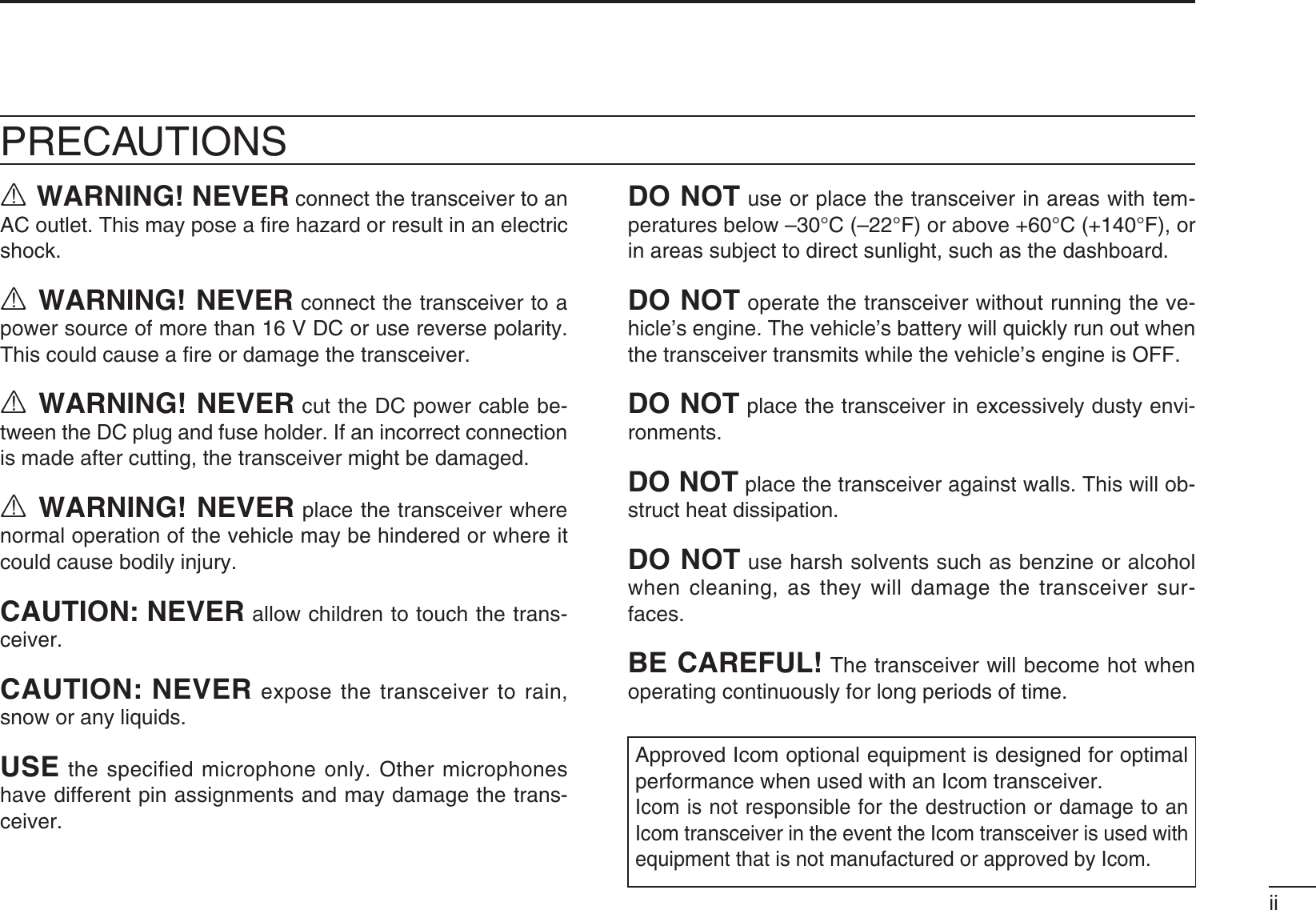
![82BASIC OPERATIONN Call procedure7HENYOURSYSTEMEMPLOYSTONESIGNALINGEXCLUDING#4#33and DTCS), a call procedure may be necessary prior to voice transmission. The tone signalling employed may be a selec-tive calling system which allows you to call specific station(s) only and prevents unwanted stations from contacting you.q3ELECTTHEDESIRED48CODECHANNELANDATONECODEaccording to your System Operator’s instructions. s4HISMAY NOT BENECESSARY DEPENDINGON THEPREPROGRAM-ming. s2EFERTOPAGESANDFORSELECTIONw Push [Call] (assigned to one of the dealer programmable keys).e After transmitting, the remainder of your communication can be carried out in the normal fashion.Selective calling Non-selective callingN Receiving and transmittingReceiving:q Hold down [] for 1 second to turn ON the power.w Push [CH Up] or [CH Down] to select a channel.e When receiving a call, rotate [VOL] to adjust the audio out-put level to a comfortable listening level../4%Depending on the preprogramming, the transceiver automatically transmits the microphone audio for the specified time period* when a matched RX code signal is received.s(-'OR(-HAND MICROPHONE is required.* Depending on the preprogramming. Ask your dealer for details.Transmitting:Wait for the channel to become clear to avoid interference.q Take the microphone off hook. s4HE@AUDIBLECONDITIONISSELECTED s!PRIORITYCHANNELMAYBEAUTOMATICALLYSELECTEDw Wait for the channel to become clear.s4HECHANNELISBUSYWHENTHE4828INDICATORLIGHTSGREENe While holding down [PTT], speak into the microphone at your normal voice level.r Release [PTT] to return to receive.)-0/24!.44OMAXIMIZETHEREADABILITYOFYOURSIGNAL 1. Pause briefly after pushing [PTT]. 2. Hold the microphone 5 to 10 cm (2 to 4 inches) from your mouth, then speak into the microphone at a normal voice level.](https://usermanual.wiki/ICOM-orporated/333502/User-Guide-1394343-Page-12.png)
![92BASIC OPERATION12345678910111213141516D Transmitting notess4RANSMITINHIBITFUNCTION The transceiver has several inhibit functions which restrict transmission under the following conditions: - The channel is muted (‘Inaudible’ mode) - The channel is busy. - Un-matched CTCSS is received. (Or matched, depending on the preprogramming) - The selected channel is a ‘receive only’ channel.s4IMEOUTTIMER After continuously transmitting for the pre-programmed time period, the time-out timer is activated, causing the trans-ceiver to stop transmitting.s0ENALTYTIMER Once the time-out timer is activated, transmission is further inhibited for a period, determined by the penalty timer.s044)$CALL The transceiver automatically sends the 5-tone, DTMF or digital ANI ID code when [PTT] is pushed (beginning of the TRANSMISSIONANDORWHENITISRELEASEDENDOFTRANSMIS-sion), depending on the preprogramming. A PTTID call also be made with the MDC 1200 signal-ing system. (p. 13)D DTMF transmissionIf the transceiver has [DTMF Autodial] assigned to it, the au-tomatic DTMF transmission function can be used.Push [DTMF Autodial] to transmit the DTMF code.](https://usermanual.wiki/ICOM-orporated/333502/User-Guide-1394343-Page-13.png)
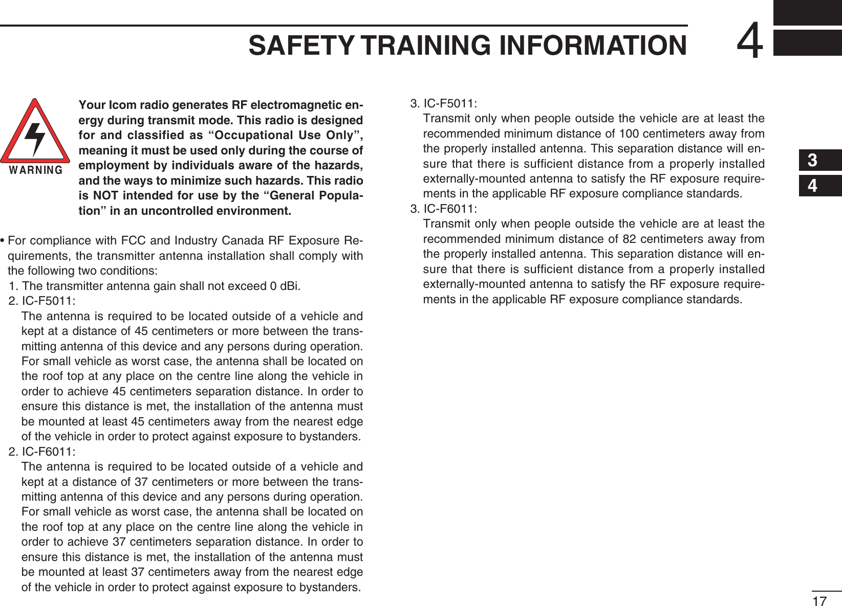
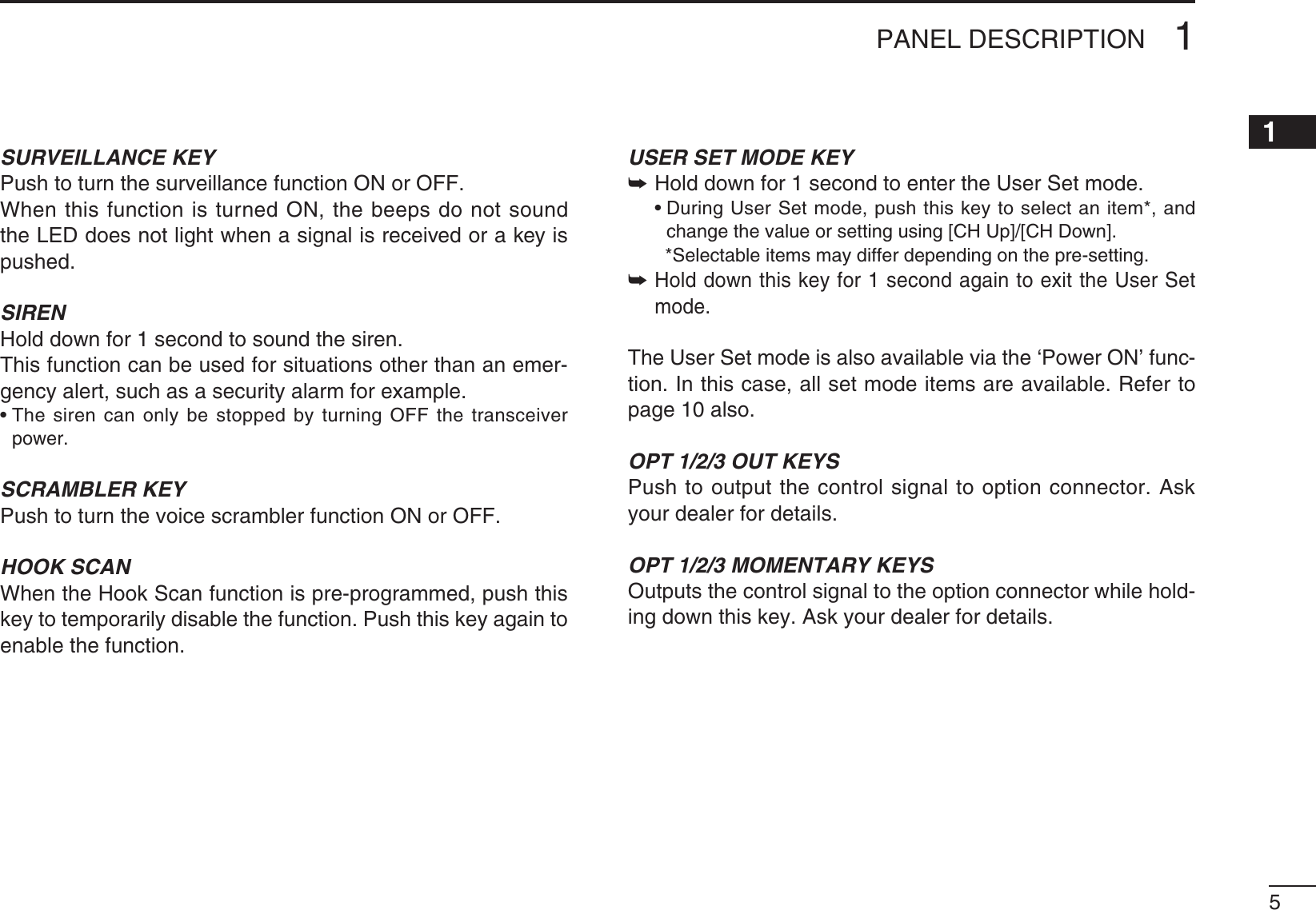
![102BASIC OPERATIONN User Set modeThe User Set mode can be accessed with the ‘Power ON’ function. In this case, all set mode items are selectable. The User Set mode allows you to set seldom-changed set-tings, and you can “customize” the transceiver operation to suit your preferences and operating style.Entering the User Set mode:q Push [] to turn OFF the power.w While holding down [P1] and [P2], push [] to turn ON the power. s(OLDDOWN;0=AND;0=CONTINUOUSLYUNTILITTURN/.TX/RX1234[P1] [P2] [ ]e Hold down [P0] for 1 second to enter the User Set mode. s(OLDDOWN;0=FORSECONDAGAINTOEXITTHE5SER3ETMODETX/RX1234[P0]r Push [P0] several times to select the appropriate item. Then, push [P2] or [P3] to set the desired level or setting. s3ELECTABLESETMODEFUNCTIONSAREBacklight, Beep ON/OFF setting, Beep Level, SQL Level, AF Min Level, Mic Gain, Horn, Signal Moni and Lone Worker. s4HE#HANNELINDICATORAND!CTIVATEDKEYINDICATORLIGHTTOSHOWthe selected item.TX/RX1234[P0] [P2] [P3]Channel indicatorActivated keyindicatort Hold down [ ] for 1 second to turn OFF the power, then ON again to return the normal operating mode.TX/RX1234[ ]The User Set mode also be selected using a programmable key. Please refer to the [User Set Mode] section on page 5 for instructions on how to use the key assigned to the User Set mode.[User Set Mode] can be used for quick item selection. Set h%NABLEvFORTHEOFTENUSEDITEMSWITHTHE#3&&F5020 CLONING SOFTWARE.](https://usermanual.wiki/ICOM-orporated/333502/User-Guide-1394343-Page-14.png)
![112BASIC OPERATION2N Scrambler functionThe Voice Scrambler function provides private communica-tion between stations.The optional Rolling or Non-rolling type can be used.Push [Scrambler] to turn ON the Scrambler function.s0USH;3CRAMBLER=AGAINTOTURN/&&THEFUNCTIONN Stun function4HEDISPATCHERCANSENDATONESIGNALTHATWILLSTUNKILLor revive your transceiver.When the Stun ID is received, a beep sounds*, and the trans-ceiver becomes unusable. Receiving a Revive command or entering the password* (p. 7) is necessary to operate the transceiver again in this case.When the Kill ID is received, a beep sounds*, and the trans-ceiver becomes unusable (the transceiver switches to the cloning required condition). Cloning the transceiver is neces-sary to operate the transceiver again in this case.* Depending on the preprogramming. Ask your dealer for de-tails.Stun function is also available with the MDC 1200 signaling system. (p. 13)N Priority A channel selectionWhen one of the following operations is performed, the trans-ceiver automatically selects the Priority A channel. s4URNING/.THEPOWER The Priority A channel is selected each time the trans-ceiver power is turned ON. s/FFHOOK The Priority A channel is selected when the microphone is taken off its hanger.](https://usermanual.wiki/ICOM-orporated/333502/User-Guide-1394343-Page-15.png)
![122BASIC OPERATIONN Emergency transmissionWhen [Emergency] is held down for the specified time pe-riod*, the emergency signal is transmitted on the specified emergency channel once, or repeatedly.When no emergency channel is specified, the call is transmit-ted on the operating channel.The repeat emergency signal is automatically transmitted until you turn OFF the power. Depending on the preprogramming, receiving a matching 5-tone code cancels the transmission.If you want to cancel the Emergency function, hold down [Emergency] for the pre-programmed time period again be-fore transmitting the call.If your transceiver is programmed for Silent operation, you can transmit emergency calls without the beep sounding and the LEDs lighting.)-0/24!.4 It is recommended to set an emergency channel individually to provide the certain emergency call operation.D NOTESDepending on the preprogramming, the following functions are automatically activated. Ask your dealer for details.s!UTO48FUNCTIONAfter the emergency call transmission, audio from the micro-phone is automatically transmitted for a specified time pe-riod.*s4HE(-'OR(-HANDMICROPHONEISREQUIREDs!UTO28FUNCTIONAfter the emergency call transmission, the transceiver stands by in the audible mode for the specified time period.** Depending on the preprogramming. Ask your dealer for de-tails.](https://usermanual.wiki/ICOM-orporated/333502/User-Guide-1394343-Page-16.png)
![1312345678910111213141516N MDC 1200 system operationThe MDC 1200 signaling system enhances your transceiver’s capabilities with PTT ID* and Emergency signaling.7HEN;044=ISPUSHEDANDORRELEASEDTHETRANSCEIVERTRANSMITSITSown station ID.D Transmitting an Emergency Call The MDC 1200 system’s Emergency feature can be ac-cessed using the [Emergency] key (p. 4). The transceiver will send an Emergency MDC 1200 system command once, or repeatedly for a programmed number of times, until it re-ceives an acknowledgement signal.The emergency call can be transmitted without a beep sound, depending on the preprogramming. Ask your dealer for de-tails.D Receiving a Stun and ReviveThe dispatcher can send MDC 1200 system signals that will stun or revive your transceiver. If a Stun command that matches your station ID is received, the transceiver will not receive or transmit. When a Revive command that matches your station ID is received, normal operation is restored.2BASIC OPERATION](https://usermanual.wiki/ICOM-orporated/333502/User-Guide-1394343-Page-17.png)