ICOM orporated 333502 UHF Mobile Transceiver User Manual IC F5020 F6020 series Instruction Manual
ICOM Incorporated UHF Mobile Transceiver IC F5020 F6020 series Instruction Manual
User Manual

INSTRUCTION MANUAL
VHF MOBILE TRANSCEIVERS
iF5010
Series
UHF MOBILE TRANSCEIVERS
iF6010
Series
Limited functions only

i
IMPORTANT
READ ALL INSTRUCTIONS carefully and com-
pletely before using the transceiver.
SAVE THIS INSTRUCTION MANUAL — This
instruction manual contains important oper ating instruc-
tions for the IC-F5011, IC-F5013, IC-F5013H VHF MOBILE
TRANSCEIVERS and the IC-F6011, IC-F6013, IC-F6013H
UHF MOBILE TRANSCEIVERS.
EXPLICIT DEFINITIONS
WORD DEFINITION
R WARNING! Personal injury, fire hazard or electric
shock may occur.
CAUTION Equipment damage may occur.
NOTE
If disregarded, inconvenience only. No risk
of personal injury, fire or electric shock.
FCC INFORMATION
s&/2#,!33"5.).4%.4)/.!,2!$)!4/23
This equipment has been tested and found to comply with
the limits for a Class B digital device, pursuant to part 15 of
the FCC Rules. These limits are designed to provide reason-
able protection against harmful interference in a residential
installation. This equipment generates, uses and can radiate
radio frequency energy and, if not installed and used in ac-
cordance with the instructions, may cause harmful interfer-
ence to radio communications. However, there is no guaran-
tee that interference will not occur in a particular installation.
If this equipment does cause harmful interference to radio or
television reception, which can be determined by turning the
equipment off and on, the user is encouraged to try to correct
the interference by one or more of the following measures:
s2EORIENTORRELOCATETHERECEIVINGANTENNA
s)NCREASETHESEPARATIONBETWEENTHEEQUIPMENTANDRE-
ceiver.
s#ONNECTTHEEQUIPMENTINTOANOUTLETONACIRCUITDIFFER-
ent from that to which the receiver is connected.
s#ONSULTTHEDEALERORANEXPERIENCEDRADIO46TECHNICIAN
for help.
Icom, Icom Inc. and the Icom logo are registered trademarks of Icom
Incorporated (Japan) in Japan, the United States, the United King-
DOM'ERMANY&RANCE3PAIN2USSIAANDOROTHERCOUNTRIES
All other products or brands are registered trademarks or trademarks
of their respective holders.
#!54)/. Changes or modifications to this transceiver,
NOTEXPRESSLYAPPROVEDBY)COM)NCCOULDVOIDYOURAU-
thority to operate this transceiver under FCC regulations.

ii
PRECAUTIONS
R WARNING! NEVER connect the transceiver to an
AC outlet. This may pose a fire hazard or result in an electric
shock.
R WARNING! NEVER connect the transceiver to a
power source of more than 16 V DC or use reverse polarity.
This could cause a fire or damage the transceiver.
R WARNING! NEVER cut the DC power cable be-
tween the DC plug and fuse holder. If an incorrect connection
is made after cutting, the transceiver might be damaged.
R WARNING! NEVER place the transceiver where
normal operation of the vehicle may be hindered or where it
could cause bodily injury.
#!54)/. NEVER allow children to touch the trans-
ceiver.
#!54)/. NEVEREXPOSETHETRANSCEIVER TO RAIN
snow or any liquids.
USE the specified microphone only. Other microphones
have different pin assignments and may damage the trans-
ceiver.
DO NOT use or place the transceiver in areas with tem-
peratures below –30°C (–22°F) or above +60°C (+140°F), or
in areas subject to direct sunlight, such as the dashboard.
DO NOT operate the transceiver without running the ve-
hicle’s engine. The vehicle’s battery will quickly run out when
the transceiver transmits while the vehicle’s engine is OFF.
DO NOTPLACETHETRANSCEIVERINEXCESSIVELYDUSTYENVI-
ronments.
DO NOT place the transceiver against walls. This will ob-
struct heat dissipation.
DO NOT use harsh solvents such as benzine or alcohol
when cleaning, as they will damage the transceiver sur-
faces.
BE CAREFUL! The transceiver will become hot when
operating continuously for long periods of time.
Approved Icom optional equipment is designed for optimal
performance when used with an Icom transceiver.
Icom is not responsible for the destruction or damage to an
Icom transceiver in the event the Icom transceiver is used with
equipment that is not manufactured or approved by Icom.

iii
TABLE OF CONTENTS
IMPORTANT .......................................................................... i
EXPLICIT DEFINITIONS ....................................................... i
FCC INFORMATION ............................................................. i
PRECAUTIONS .................................................................... ii
TABLE OF CONTENTS ....................................................... iii
1 PANEL DESCRIPTION ................................................1–6
N Front panel ...................................................................1
N Function LED ...............................................................2
N Programmable function keys ........................................3
2 BASIC OPERATION ..................................................7–13
N Turning ON the power ..................................................7
N Channel selection .........................................................7
N Call procedure ..............................................................8
N Receiving and transmitting ...........................................8
N User Set mode ...........................................................10
N Scrambler function .....................................................11
N Stun function ..............................................................11
N Priority A channel selection ........................................11
N Emergency transmission ............................................12
N MDC 1200 system operation ......................................13
3 CONNECTION AND MAINTENANCE ....................14–16
N Rear panel connection ...............................................14
N Supplied Accessories .................................................15
N Mounting the transceiver ............................................15
N Antenna ......................................................................16
N Fuse replacement ......................................................16
N Cleaning .....................................................................16
N Options .......................................................................16
4 SAFETY TRAINING INFORMATION .............................17
1
1
PANEL DESCRIPTION
1
2
3
4
5
6
7
8
9
10
11
12
13
14
15
16
TX/RX
1234
P0 P1 P2 P3
q
e
SpeakerFunction LED (p. 2)
rw
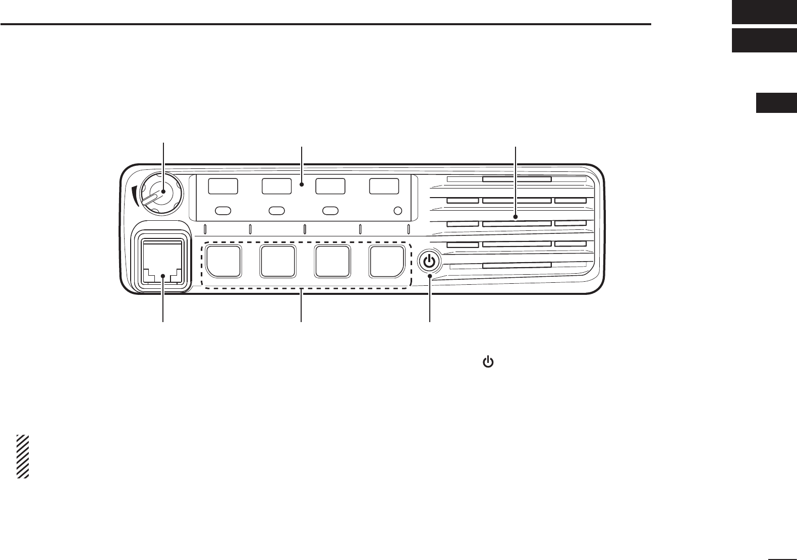
N Front panel
q AF VOLUME CONTROL KNOB [VOL]
Rotate the knob to adjust the audio output level.
s-INIMUMAUDIOLEVELISPRESETP
w MICROPHONE CONNECTOR
Connect the supplied or optional microphone.
NEVER connect non-specified microphones. The pin
assignments may be different and the transceiver may
be damaged.
e DEALER-PROGRAMMABLE KEYS
Desired functions can be independently programmed by
your dealer. (p. 3)
r POWER KEY [ ]
Push to turn the power ON or OFF.
s4HEFOLLOWINGOPTIONALFUNCTIONSAREAVAILABLEATPOWER/.
- Automatic scan start
- Password prompt
- User Set mode

2
1PANEL DESCRIPTION
N Function LED
q CHANNEL INDICATORS
± Indicates the operating channel.
± Blinks when receiving a signal during a scan.
± All LEDs blink while entering the power ON password.
w TX/RX INDICATOR
± Lights red while transmitting.
± Lights green while the channel is busy (receiving).
± Blinks orange when the specified 2-tone, 5-tone call is
received.
± Alternately blinks green and red when a cloning error
has occurred.
e ACTIVATED KEY INDICATORS (P0/P1/P2)
Lights when a pre-programmed key function is activated.
./4% When the supplied DC voltage is low, all LEDs
blink
. Check the DC voltage.
D MICROPHONE
The supplied or optional microphone has a PTT switch and
a hanger hook.
s4HEFOLLOWINGFUNCTIONSAREAVAILABLEWHENTHEMICROPHONEIS/.OR
OFF hook (depending on the preprogramming):
- Automatic scan start when you put it ON hook.
- Scan is cancelled when you take it OFF hook
- Scan is paused when you take it OFF hook
- Automatically selects the Priority A channel when you take it OFF
hook.
- Sets to ‘Inaudible’ mode (muted state) when you put it ON hook.
- Sets to ‘Audible’ mode (unmuted state) when you take it OFF
hook.
TX/RX
1234
q
we

3
1
PANEL DESCRIPTION
1
2
3
4
5
6
7
8
9
10
11
12
13
14
15
16
N Programmable function keys
The following functions can be assigned to [P0], [P1], [P2]
and [P3] programmable function keys.
Consult your Icom dealer or system operator for details con-
cerning your transceivers programming.
CH UP AND DOWN KEYS
Push to select an operating channel.
SCAN A START/STOP KEY
Push to start or cancel a scan.
SCAN B START/STOP KEY
Push to start or cancel a scan.
When a scan started with the Power ON Scan or by pushing
THIS KEY PUSH TO CANCEL IT )F THE SCAN IS CANCELLED EXCEPT
by pushing this key, the cancelled scan resumes after the
specified time period.
SCAN ADD/DEL (TAG) KEY
While scan is paused by a detected signal, on a channel
other than a priority channel, push this key to clear the chan-
nel from the scan list.
Depending on the preprogramming, the cleared channel is
added to the scan list again after the scan is cancelled.
PRIO A/B KEYS
± Push to select Priority Channel A or B.
± To rewrite the operating channel as Priority A or Priority
B, hold down [Prio A (Rewrite)] or [Prio B (Rewrite)] for
1second.
MR-CH 1/2/3/4 KEYS
Push to directly select memory channels 1 to 4.
MONI (AUDI) KEY
±0USHTOTURNTHE#4#33$4#3ORTONESQUELCH-UTE
ON or OFF.
s/NLYDURING,-2OPERATIONHOLDDOWNTOOPENANYSQUELCH
functions, or deactivate any mute functions.
s/NLYDURING0-2OPERATIONPUSHTOACTIVATEONEORTWOOFTHE
following functions* on each channel.
- Hold down to unmute the channel (Audible mode).
- Push to mute the channel (Inaudible mode).
- Push to send a ‘reset code’ after the communication is fin-
ished.
*Ask your dealer for details.
./4% After a specified period, the un-muted state (‘Au-
dible’ mode) may automatically return to the muted state
(‘Inaudible’ mode), depending on the preprogramming.
± Hold down this key for 1 second to cancel a scan, depend-
ing on the preprogramming.

4
1PANEL DESCRIPTION
N Programmable function keys (continued)
LONE WORKER KEY
Push to turn the Lone Worker function ON or OFF.
s)FTHE,ONE7ORKERFUNCTIONISACTIVATEDTHE%MERGENCYFUNCTIONIS
automatically turned ON after the specified time period has passed
with no operation performed.
HIGH/LOW KEY
Push to select the transmit output power level temporarily or
permanently, depending on the preprogramming.
s!SKYOURDEALERFORTHEOUTPUTPOWERLEVELFOREACHSELECTION
TALK AROUND KEY
Push to turn the talk around function ON or OFF.
s4HETALKAROUNDFUNCTIONEQUALIZESTHETRANSMITFREQUENCYTOTHE
receive frequency for transceiver-to-transceiver communication.
WIDE/NARROW KEY
Push to toggle the IF bandwidth between wide and narrow.
s4HEWIDEPASSBANDWIDTHCANBESELECTEDFROMORK(Z
USINGTHE#3&&&CLONING SOFTWARE. (PMR op-
eration only) Ask your dealer for details.
DTMF AUTODIAL KEY
Push to transmit a DTMF code.
RE-DIAL KEY
Push to transmit the last-transmitted DTMF code.
s48MEMORIESARECLEAREDAFTERTURNING/&&THETRANSCEIVER
CALL KEYS
0USHTOTRANSMITATONE)$CODE
s4ONECALLTRANSMISSIONMAYBENECESSARYBEFOREYOUCALLANOTHER
station, depending on your signalling system.
s;#ALL!=ANDOR;#ALL"=MAYBESELECTABLEWHENYOURSYSTEMEM-
PLOYSSELECTIVE@)NDIVIDUAL'ROUPCALLS!SKYOURDEALERWHICHCALL
is assigned to each key.
EMERGENCY KEY
Hold down for a specified period to transmit an emergency
call.
s"EEPSSOUNDWHENTHEEMERGENCYCALLISTRANSMITTED
s4HETRANSCEIVERCANTRANSMITANEMERGENCYCALLWITHOUTTHEBEEP
sounding and the LED indicator lighting. Ask your dealer for de-
tails.
s)FYOUWANTTOCANCELTHEEMERGENCYCALLHOLDDOWNTHEKEYAGAIN
before transmitting the call.
s4HEEMERGENCYCALLISTRANSMITTEDONLYONETIMEORREPEATEDLYUNTIL
receiving an acknowledgement signal, or until the power is turned
OFF.
When a matched 5-tone code signal is received, the emergency
function can be cancelled depending on the presetting. (PMR op-
eration only)

5
1
PANEL DESCRIPTION
1
SURVEILLANCE KEY
Push to turn the surveillance function ON or OFF.
When this function is turned ON, the beeps do not sound
the LED does not light when a signal is received or a key is
pushed.
SIREN
Hold down for 1 second to sound the siren.
This function can be used for situations other than an emer-
GENCYALERTSUCHASASECURITYALARMFOREXAMPLE
s4HESIRENCANONLY BESTOPPEDBY TURNING/&&THETRANSCEIVER
power.
SCRAMBLER KEY
Push to turn the voice scrambler function ON or OFF.
HOOK SCAN
When the Hook Scan function is pre-programmed, push this
key to temporarily disable the function. Push this key again to
enable the function.
USER SET MODE KEY
± Hold down for 1 second to enter the User Set mode.
s$URING5SER3ETMODEPUSHTHISKEYTOSELECTANITEMAND
CHANGETHEVALUEORSETTINGUSING;#(5P=;#($OWN=
*Selectable items may differ depending on the pre-setting.
±
(OLDDOWNTHISKEYFORSECONDAGAINTOEXITTHE5SER3ET
mode.
The User Set mode is also available via the ‘Power ON’ func-
tion. In this case, all set mode items are available. Refer to
page 10 also.
OPT 1/2/3 OUT KEYS
Push to output the control signal to option connector. Ask
your dealer for details.
OPT 1/2/3 MOMENTARY KEYS
Outputs the control signal to the option connector while hold-
ing down this key. Ask your dealer for details.

6
1PANEL DESCRIPTION
N Programmable function keys (continued)
Ext. CH Sel Mode KEY
0USHTOTURNTHE%XT#(3ELECTFUNCTION/.OR/&&
When the function is turned ON, memory channels can be
SELECTEDWITHEXTERNALINPUTOPERATIONONLY
When the function is turned OFF, memory channels can be
SELECTEDWITH;#(5P=OR;#($OWN=OPERATIONORWITHEXTER-
nal input operation.
s4HISFUNCTIONISAVAILABLEWHENTHEEXTERNALUNITSUCHASADIMMER
control is connected to the transceiver with the optional OPC-1939
or OPC-2078 cable (p. 16).
s!SKYOURDEALERFORDETAILSOFEXTERNALINPUTOPERATION

7
2
BASIC OPERATION
1
2
3
4
5
6
7
8
9
10
11
12
13
14
15
16
N Turning ON the power
q Push [ ] to turn ON the power.
w If the transceiver is programmed for a start up password,
input the digit codes as directed by your dealer.
s4HEKEYSSHOWNBELOWCANBEUSEDFORPASSWORDINPUT
The transceiver detects numbers in the same block as identical.
Therefore “01234” and “56789” are the same.
e If all channel indicator LEDs still blink after inputting 4 dig-
its, the input code number may be incorrect. Turn OFF the
power and re-enter your password.
N Channel selection
There are several methods to select channels, and they may
differ, according to your system set up.
Push [CH Up] or [CH Down] to sequentially select the desired
operating channel, or push one of the [MR-CH 1] to [MR-CH 4]
keys to select a channel directly.
AUTOMATIC SCAN TYPE:
Channel setting is not necessary for this type. When turn-
ing ON power, the transceiver automatically starts scanning.
Scanning stops when a signal is detected.
KEY
NUMBER 0
5
4
9
3
8
2
7
1
6
P0 P1 P2 P3
8
2BASIC OPERATION
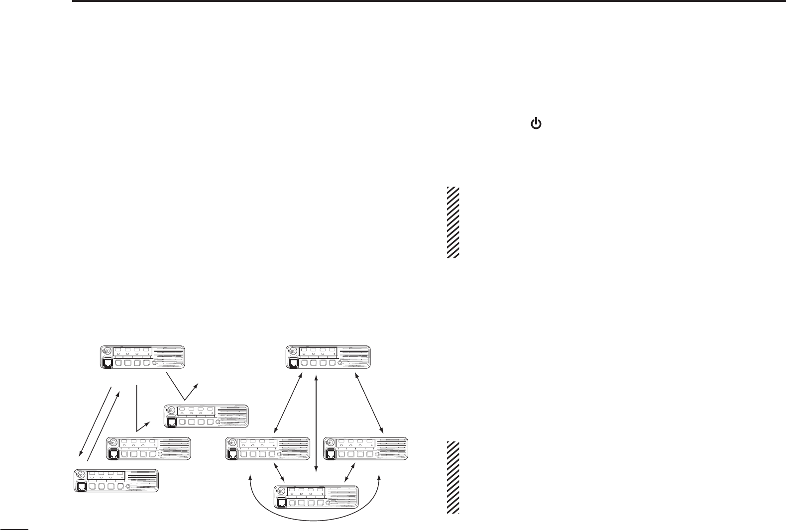
N Call procedure
7HENYOURSYSTEMEMPLOYSTONESIGNALINGEXCLUDING#4#33
and DTCS), a call procedure may be necessary prior to voice
transmission. The tone signalling employed may be a selec-
tive calling system which allows you to call specific station(s)
only and prevents unwanted stations from contacting you.
q3ELECTTHEDESIRED48CODECHANNELANDATONECODE
according to your System Operator’s instructions.
s4HISMAY NOT BENECESSARY DEPENDINGON THEPREPROGRAM-
ming.
s2EFERTOPAGESANDFORSELECTION
w Push [Call] (assigned to one of the dealer programmable
keys).
e After transmitting, the remainder of your communication
can be carried out in the normal fashion.
Selective calling Non-selective calling
N Receiving and transmitting
Receiving:
q Hold down [] for 1 second to turn ON the power.
w Push [CH Up] or [CH Down] to select a channel.
e When receiving a call, rotate [VOL] to adjust the audio out-
put level to a comfortable listening level.
./4%
Depending on the preprogramming, the transceiver
automatically transmits the microphone audio for the specified
time period* when a matched RX code signal is received.
s(-'OR(-HAND MICROPHONE is required.
* Depending on the preprogramming. Ask your dealer for details.
Transmitting:
Wait for the channel to become clear to avoid interference.
q Take the microphone off hook.
s4HE@AUDIBLECONDITIONISSELECTED
s!PRIORITYCHANNELMAYBEAUTOMATICALLYSELECTED
w Wait for the channel to become clear.
s
4HECHANNELISBUSYWHENTHE4828INDICATORLIGHTSGREEN
e While holding down [PTT], speak into the microphone at
your normal voice level.
r Release [PTT] to return to receive.
)-0/24!.44OMAXIMIZETHEREADABILITYOFYOURSIGNAL
1. Pause briefly after pushing [PTT].
2. Hold the microphone 5 to 10 cm (2 to 4 inches) from
your mouth, then speak into the microphone at a normal
voice level.

9
2
BASIC OPERATION
1
2
3
4
5
6
7
8
9
10
11
12
13
14
15
16
D Transmitting notes
s4RANSMITINHIBITFUNCTION
The transceiver has several inhibit functions which restrict
transmission under the following conditions:
- The channel is muted (‘Inaudible’ mode)
- The channel is busy.
- Un-matched CTCSS is received.
(Or matched, depending on the preprogramming)
- The selected channel is a ‘receive only’ channel.
s4IMEOUTTIMER
After continuously transmitting for the pre-programmed time
period, the time-out timer is activated, causing the trans-
ceiver to stop transmitting.
s0ENALTYTIMER
Once the time-out timer is activated, transmission is further
inhibited for a period, determined by the penalty timer.
s044)$CALL
The transceiver automatically sends the 5-tone, DTMF or
digital ANI ID code when [PTT] is pushed (beginning of the
TRANSMISSIONANDORWHENITISRELEASEDENDOFTRANSMIS-
sion), depending on the preprogramming.
A PTTID call also be made with the MDC 1200 signal-
ing system. (p. 13)
D DTMF transmission
If the transceiver has [DTMF Autodial] assigned to it, the au-
tomatic DTMF transmission function can be used.
Push [DTMF Autodial] to transmit the DTMF code.
10
2BASIC OPERATION
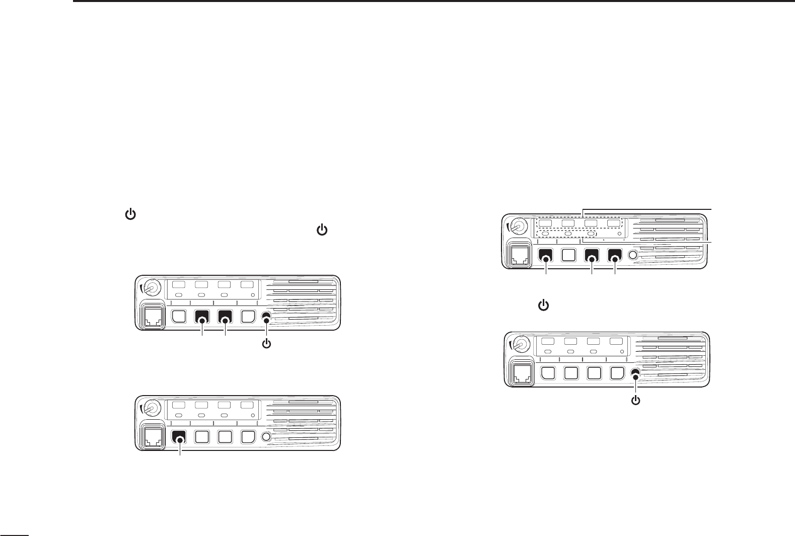
N User Set mode
The User Set mode can be accessed with the ‘Power ON’
function. In this case, all set mode items are selectable.
The User Set mode allows you to set seldom-changed set-
tings, and you can “customize” the transceiver operation to
suit your preferences and operating style.
Entering the User Set mode:
q Push [] to turn OFF the power.
w While holding down [P1] and [P2], push [] to turn ON the
power.
s(OLDDOWN;0=AND;0=CONTINUOUSLYUNTILITTURN/.
TX/RX
1234
[P1] [P2] [ ]
e Hold down [P0] for 1 second to enter the User Set mode.
s(OLDDOWN;0=FORSECONDAGAINTOEXITTHE5SER3ETMODE
TX/RX
1234
[P0]
r Push [P0] several times to select the appropriate item.
Then, push [P2] or [P3] to set the desired level or setting.
s3ELECTABLESETMODEFUNCTIONSAREBacklight, Beep ON/OFF
setting, Beep Level, SQL Level, AF Min Level, Mic Gain,
Horn, Signal Moni and Lone Worker.
s4HE#HANNELINDICATORAND!CTIVATEDKEYINDICATORLIGHTTOSHOW
the selected item.
TX/RX
1234
[P0] [P2] [P3]
Channel indicator
Activated key
indicator
t Hold down [ ] for 1 second to turn OFF the power, then
ON again to return the normal operating mode.
TX/RX
1234
[ ]
The User Set mode also be selected using a programmable
key. Please refer to the [User Set Mode] section on page 5
for instructions on how to use the key assigned to the User
Set mode.
[User Set Mode] can be used for quick item selection. Set
h%NABLEvFORTHEOFTENUSEDITEMSWITHTHE#3&&
F5020 CLONING SOFTWARE.

11
2
BASIC OPERATION
2
N Scrambler function
The Voice Scrambler function provides private communica-
tion between stations.
The optional Rolling or Non-rolling type can be used.
Push [Scrambler] to turn ON the Scrambler function.
s0USH;3CRAMBLER=AGAINTOTURN/&&THEFUNCTION
N Stun function
4HEDISPATCHERCANSENDATONESIGNALTHATWILLSTUNKILL
or revive your transceiver.
When the Stun ID is received, a beep sounds*, and the trans-
ceiver becomes unusable. Receiving a Revive command or
entering the password* (p. 7) is necessary to operate the
transceiver again in this case.
When the Kill ID is received, a beep sounds*, and the trans-
ceiver becomes unusable (the transceiver switches to the
cloning required condition). Cloning the transceiver is neces-
sary to operate the transceiver again in this case.
* Depending on the preprogramming. Ask your dealer for de-
tails.
Stun function is also available with the MDC 1200 signaling
system. (p. 13)
N Priority A channel selection
When one of the following operations is performed, the trans-
ceiver automatically selects the Priority A channel.
s4URNING/.THEPOWER
The Priority A channel is selected each time the trans-
ceiver power is turned ON.
s/FFHOOK
The Priority A channel is selected when the microphone
is taken off its hanger.

12
2BASIC OPERATION
N Emergency transmission
When [Emergency] is held down for the specified time pe-
riod*, the emergency signal is transmitted on the specified
emergency channel once, or repeatedly.
When no emergency channel is specified, the call is transmit-
ted on the operating channel.
The repeat emergency signal is automatically transmitted
until you turn OFF the power.
Depending on the preprogramming, receiving a matching
5-tone code cancels the transmission.
If you want to cancel the Emergency function, hold down
[Emergency] for the pre-programmed time period again be-
fore transmitting the call.
If your transceiver is programmed for Silent operation, you
can transmit emergency calls without the beep sounding and
the LEDs lighting.
)-0/24!.4 It is recommended to set an emergency
channel individually to provide the certain emergency call
operation
.
D NOTES
Depending on the preprogramming, the following functions
are automatically activated. Ask your dealer for details.
s!UTO48FUNCTION
After the emergency call transmission, audio from the micro-
phone is automatically transmitted for a specified time pe-
riod.*
s4HE(-'OR(-HANDMICROPHONEISREQUIRED
s!UTO28FUNCTION
After the emergency call transmission, the transceiver stands
by in the audible mode for the specified time period.*
* Depending on the preprogramming. Ask your dealer for de-
tails.

13
1
2
3
4
5
6
7
8
9
10
11
12
13
14
15
16
N MDC 1200 system operation
The MDC 1200 signaling system enhances your transceiver’s
capabilities with PTT ID* and Emergency signaling
.
7HEN;044=ISPUSHEDANDORRELEASEDTHETRANSCEIVERTRANSMITSITS
own station ID.
D Transmitting an Emergency Call
The MDC 1200 system’s Emergency feature can be ac-
cessed using the [Emergency] key (p. 4). The transceiver
will send an Emergency MDC 1200 system command once,
or repeatedly for a programmed number of times, until it re-
ceives an acknowledgement signal.
The emergency call can be transmitted without a beep sound,
depending on the preprogramming. Ask your dealer for de-
tails.
D Receiving a Stun and Revive
The dispatcher can send MDC 1200 system signals that
will stun or revive your transceiver. If a Stun command that
matches your station ID is received, the transceiver will not
receive or transmit. When a Revive command that matches
your station ID is received, normal operation is restored.
2
BASIC OPERATION
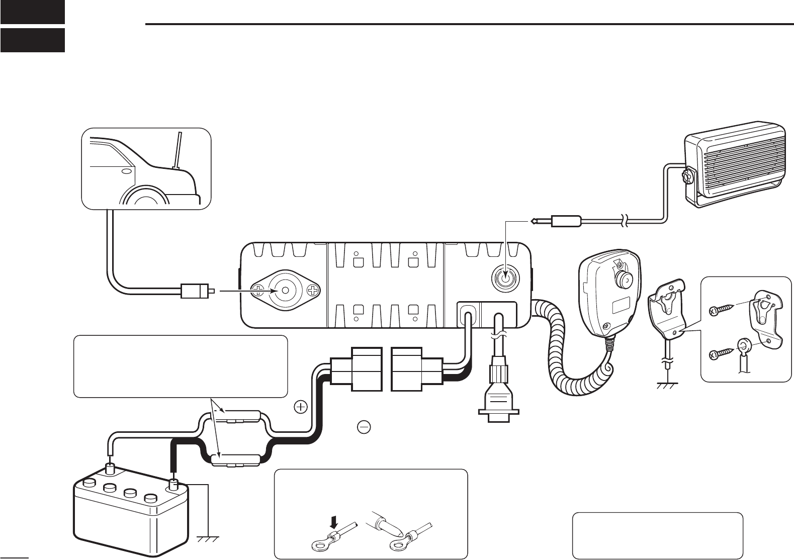
e
r
Antenna
Black
Red
12V
Battery
Solder
Crimp
NO4% Use the terminals as shown
for the cable connections.
q ANTENNA CONNECTOR
Connect to an antenna. Ask your
dealer about antenna selection
and placement.
qw
w EXTERNAL SPEAKER JACK
Connect to a 4 to 8 ø eXTERnal speaker.
e MICROPHONE HANGER
Connect the supplied micro-
phone hanger to the vehicle’s
ground for microphone ONOFF
hook functions. (See page 2)
r
OPTIONAL CABLE (OPC-1939, OPC-2078
)
t
t DC POWER RECEPTACLE
Connect to a 12 V DC battery.
Pay attention to polarities.
Optional speaker
Connect an eXTErnal modem,
dimmer control, etc.
R WARNING! NEVER connect
to a 24 V battery. This could
damage the transceiver.
R WARNING! NEVER remove the
fuse-holders from the DC power cable.
(Depending on version, the fuse holder
may not be attached to the black cable.)
N Rear panel connection
3CONNECTION AND MAINTENANCE
14
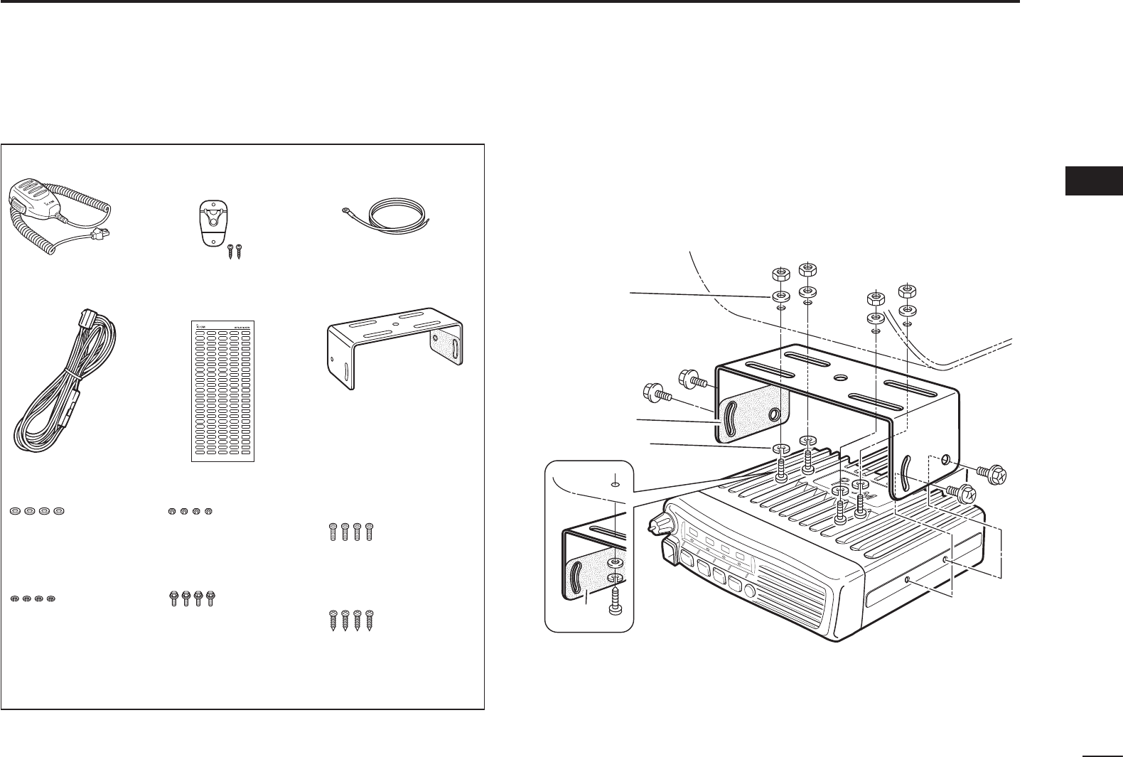
N Supplied Accessories N Mounting the transceiver
The universal mounting bracket supplied with your trans-
ceiver also allows overhead mounting.
s-OUNTTHETRANSCEIVERSECURELYWITHTHESUPPLIEDSCREWS
to a thick surface which can support more than 1.5 kg
(3.3 lb).
Flat washer
Felt*
Spring washer
When using
self-tapping screws
Felt*
*Felt reduces the effects of vibration.
CONNECTION AND MAINTENANCE 3
1
2
16
15
14
13
12
11
10
9
8
7
6
5
4
15
3
Microphone Microphone hanger
and screw set
Microphone
hanger cable
DC power cable
Flat washers
Spring washers Bracket bolts
Mounting screws
(5×12)
Self-tapping screws
(5×20)
Nuts
Function name
stickers*
Used for labelling the programmable function
keys, according to their assinged functions.
*
Mounting bracket

16
3CONNECTION AND MAINTENANCE
N Antenna
A key element in the performance of any communication sys-
tems is the antenna. Contact your dealer for more information
regarding antennas and how to install them.
N Fuse replacement
A fuse is installed in each fuse holder of the supplied DC
power cable*. If a fuse blows or the transceiver stops func-
tioning, track down the source of the problem if possible, re-
paire it and then replace the damaged fuse with a new rated
one.
*Depending on the version, only 1 fuse holder may be attached.
Q&USERATING!FORFUSEHOLDER!FORFUSEHOLDERS
USE the applicable fuse only.
N Cleaning
If the transceiver becomes dusty or dirty, wipe it clean with a
soft, dry cloth.
DO NOT use harsh solvents such as benzine or
alcohol, as they will damage the transceiver sur-
faces.
N Options
s/0#!/0#DC POWER CABLE
2 fuse holders are attached. USE only a 20 A fuse.
OPC-1132A : 3 m (9.8 ft)
OPC-347 : 7 m (23 ft)
s/0#/0#ACC CABLE
!LLOWSYOUTOCONNECTTOANEXTERNALTERMINAL
OPC-1939: D-sub 15-pin, OPC-2078: D-sub 25-pin
sHM-152/HM-152T/HM-148G/HM-148T HAND MICROPHONE
HM-152 : Hand microphone
HM-152T : DTMF microphone
HM-148G : Self grounding heavy duty microphone
HM-148T : Self grounding heavy duty DTMF microphone
sSM-26 DESKTOP MICROPHONE
sSP-22/SP-30 EXTERNAL SPEAKER
Input impedance : 4 ø
30 2ATEDINPUT7-AXINPUT7
30 2ATEDINPUT7-AXINPUT7
sUT-108R DTMF DECODER UNIT
provides pager and code squelch capabilities.
sUT-109R/UT-110R VOICE SCRAMBLER UNIT
Non-rolling type (UT-109R) and Rolling type (UT-110R)
voice scrambler units provides higher communication secu-
rity.

4
SAFETY TRAINING INFORMATION
WARNING
Your Icom radio generates RF electromagnetic en-
ergy during transmit mode. This radio is designed
for and classified as “Occupational Use Only”,
meaning it must be used only during the course of
employment by individuals aware of the hazards,
and the ways to minimize such hazards. This radio
is NOT intended for use by the “General Popula-
tion” in an uncontrolled environment.
s&ORCOMPLIANCEWITH&##AND)NDUSTRY#ANADA2&%XPOSURE2E-
quirements, the transmitter antenna installation shall comply with
the following two conditions:
4HETRANSMITTERANTENNAGAINSHALLNOTEXCEEDD"I
2. IC-F5011:
The antenna is required to be located outside of a vehicle and
kept at a distance of 45 centimeters or more between the trans-
mitting antenna of this device and any persons during operation.
For small vehicle as worst case, the antenna shall be located on
the roof top at any place on the centre line along the vehicle in
order to achieve 45 centimeters separation distance. In order to
ensure this distance is met, the installation of the antenna must
be mounted at least 45 centimeters away from the nearest edge
OFTHEVEHICLEINORDERTOPROTECTAGAINSTEXPOSURETOBYSTANDERS
2. IC-F6011:
The antenna is required to be located outside of a vehicle and
kept at a distance of 37 centimeters or more between the trans-
mitting antenna of this device and any persons during operation.
For small vehicle as worst case, the antenna shall be located on
the roof top at any place on the centre line along the vehicle in
order to achieve 37 centimeters separation distance. In order to
ensure this distance is met, the installation of the antenna must
be mounted at least 37 centimeters away from the nearest edge
OFTHEVEHICLEINORDERTOPROTECTAGAINSTEXPOSURETOBYSTANDERS
3. IC-F5011:
Transmit only when people outside the vehicle are at least the
recommended minimum distance of 100 centimeters away from
the properly installed antenna. This separation distance will en-
sure that there is sufficient distance from a properly installed
EXTERNALLYMOUNTEDANTENNATOSATISFYTHE2&EXPOSUREREQUIRE-
MENTSINTHEAPPLICABLE2&EXPOSURECOMPLIANCESTANDARDS
3. IC-F6011:
Transmit only when people outside the vehicle are at least the
recommended minimum distance of 82 centimeters away from
the properly installed antenna. This separation distance will en-
sure that there is sufficient distance from a properly installed
EXTERNALLYMOUNTEDANTENNATOSATISFYTHE2&EXPOSUREREQUIRE-
MENTSINTHEAPPLICABLE2&EXPOSURECOMPLIANCESTANDARDS
1
2
5
6
7
8
9
10
11
12
13
14
15
16
17
3
4

18
4SAFETY TRAINING INFORMATION
CAUTION
To ensure that your exposure to RF electromag-
netic energy is within the FCC allowable limits for
occupational use, always adhere to the following
GUIDELINES
sDO NOT operate the radio without a proper antenna attached, as
THISMAYDAMAGETHERADIOANDMAYALSOCAUSEYOUTOEXCEED&##
2&EXPOSURELIMITS!PROPERANTENNAISTHEANTENNASUPPLIEDWITH
this radio by the manufacturer or an antenna specifically authorized
by the manufacturer for use with this radio.
sDO NOT transmit for more than 50% of total radio use time (“50%
duty cycle”). Transmitting more than 50% of the time can cause
&##2&EXPOSURECOMPLIANCEREQUIREMENTSTOBEEXCEEDED4HE
RADIOISTRANSMITTINGWHENTHE4828INDICATORLIGHTSRED9OUCAN
cause the radio to transmit by pressing the “PTT” switch.
Electromagnetic Interference/Compatibility
During transmissions, your Icom radio generates RF energy that
can possibly cause interference with other devices or systems. To
avoid such interference, turn OFF the radio in areas where signs are
posted to do so. DO NOT operate the transmitter in areas that are
sensitive to electromagnetic radiation such as hospitals, aircraft, and
blasting sites.

MEMO
1
2
3
4
5
6
7
8
9
10
11
12
13
14
15
16

1-1-32 Kamiminami, Hirano-ku, Osaka 547-0003, Japan
A-6902H-1EX
Printed in Japan
© 2010 Icom Inc.
Printed on recycled paper with soy ink.