ICOM orporated 333800 VHF Marine Transceiver User Manual
ICOM Incorporated VHF Marine Transceiver
UserManual.wiki
>
ICOM orporated
>
333800 User Manual
User Manual
Navigation menu
Upload a User Manual
Namespaces
Wiki Guide
HTML
PDF
Info
Views
User Manual
Discussion / Help
Navigation
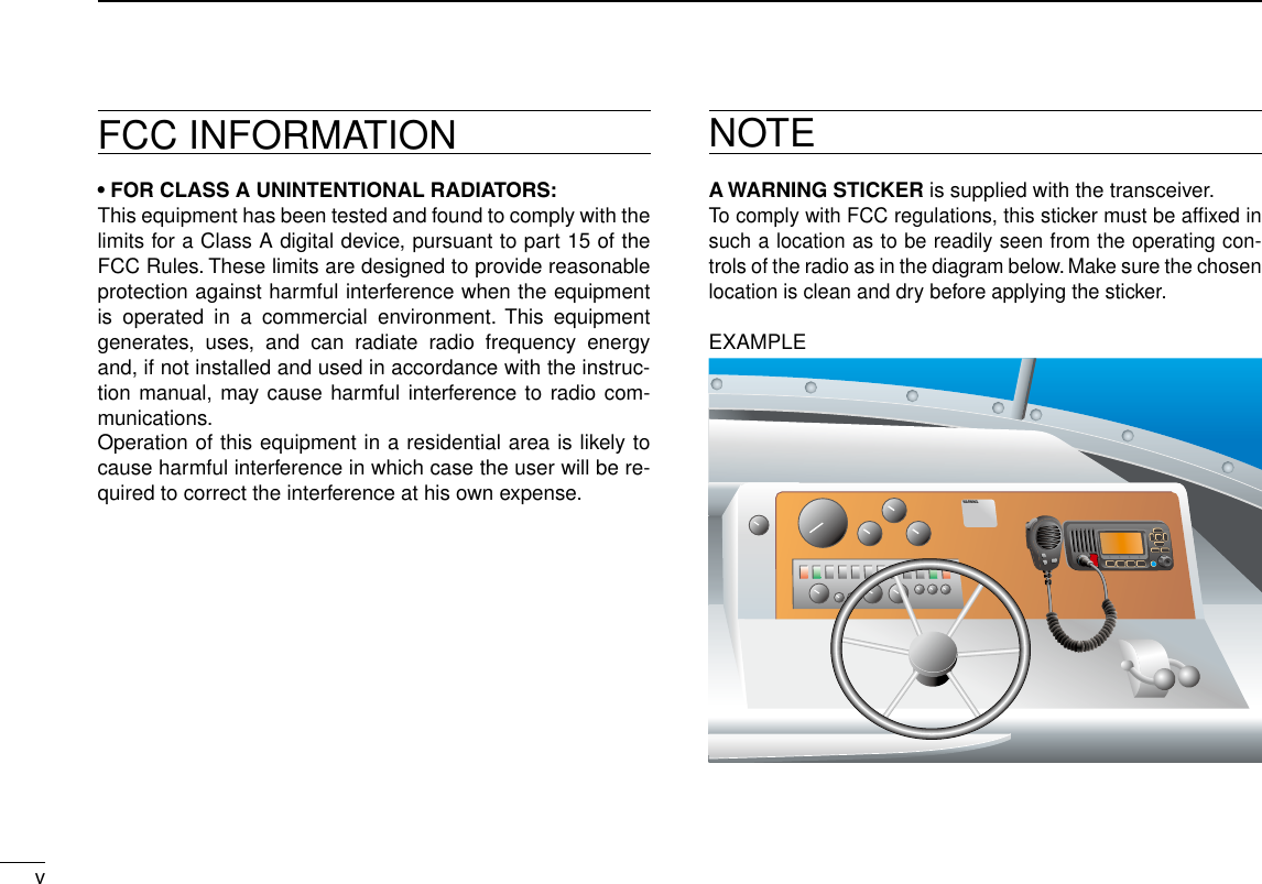
![If your vessel requires assistance, contact other vessels and the Coast Guard by sending a Distress call on Channel 16. Or, transmit your Distress call using digital selective calling on Channel 70.USING CHANNEL 16DISTRESS CALL PROCEDURE1. “MAYDAY MAYDAY MAYDAY.”2. “THIS IS ...............” (name of vessel).3. Say your call sign or other description of the vessel (AND 9 digit DSC ID if you have one).4. “LOCATED AT ...............” (your position).5. State the nature of the distress and assistance re-quired.6. Give any other information which might facilitate the rescue.USING DIGITAL SELECTIVE CALLING (Ch 70)DISTRESS CALL PROCEDURE1. While lifting up the key cover, hold down [DIS-TRESS] for 3 seconds until you hear 3 short beeps and then one long beep.2. Wait for an acknowledgment on Channel 70 from a coast station. •Aftertheacknowledgementisreceived,Channel16isautomatically selected.3. Hold down [PTT], then transmit the appropriate in-formation as listed above.iiIN CASE OF EMERGENCY](https://usermanual.wiki/ICOM-orporated/333800/User-Guide-1676007-Page-3.png)
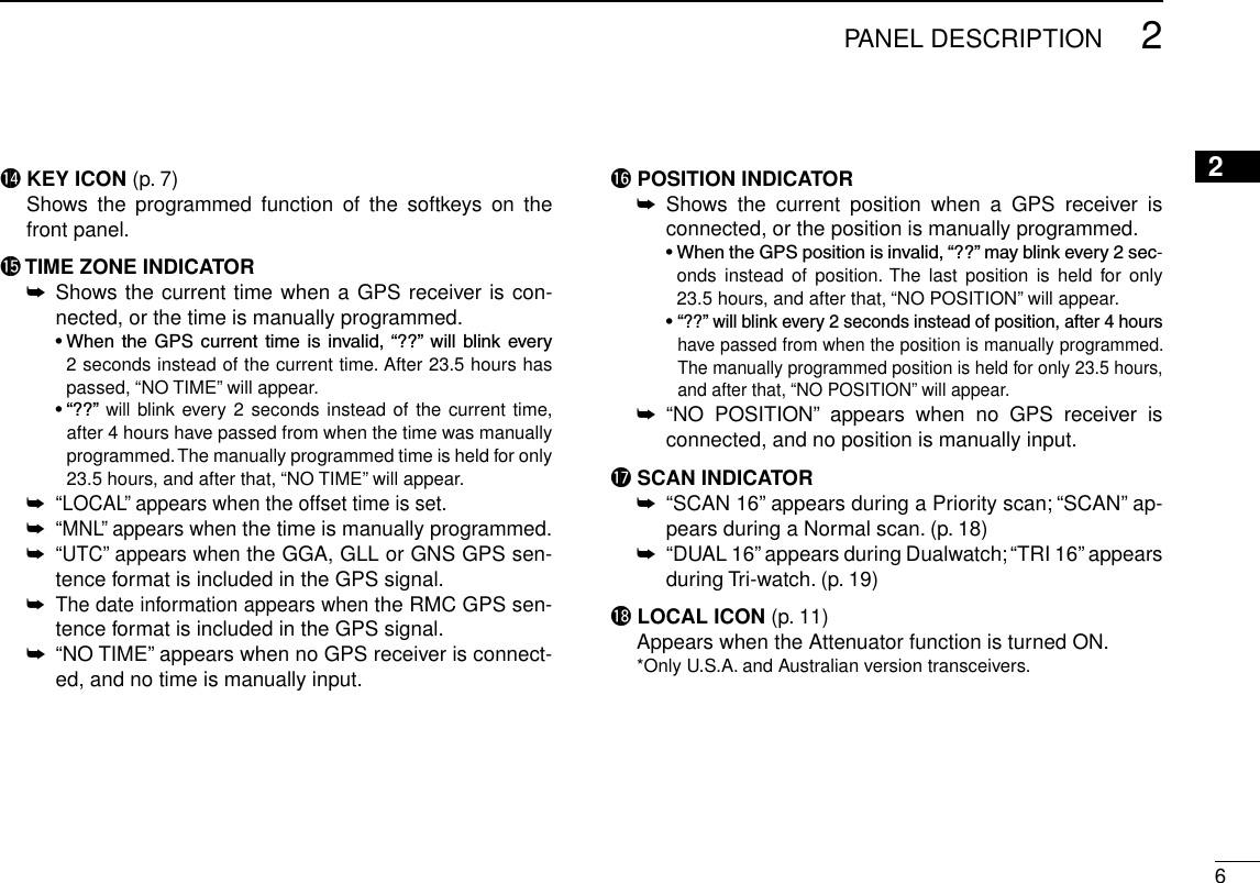
![22PANEL DESCRIPTION12345678910111213141516Front panel ■tuywerioqFunction display (p. 5)Speakerq DISTRESS KEY [DISTRESS] (pp. 24, 25) Hold down for 3 seconds to transmit a Distress call.w ENTER KEY [ENT] (pp. 8, 10, 75) Push to set the input data, selected item, and so on.e LEFT AND RIGHT KEYS [Ω]/[≈] Push to switch to the previous or next key function that ➥is assigned to the softkeys. (p. 7) Push to select the desired character or number in the ➥table while in the channel name, position, MMSI code programming mode, and so on. (pp. 8, 13, 23)r UP AND DOWN/CHANNEL SELECT KEYS [∫•CH]/[√•CH] Push to select the operating channels, Menu items, ➥Menu settings, and so on. (pp. 11, 75) ➥Push to check TAG channels, change the scanning di-rection or manually resume a scan. (p. 18)t CLEAR KEY [CLEAR] (pp. 8, 13, 75) Push to cancel the entered data, or to exit the Menu screen.y MENU KEY [MENU] (p. 75) Push to enter or exit the Menu screen.u VOLUME AND SQUELCH SWITCH/POWER SWITCH [VOL/SQL•PWR] When the power is OFF, hold down for 1 second to turn ➥ON power. (p. 11)Hold down for 1 second to turn OFF power. ➥ When the power is ON, push to enter the volume level ➥adjustment mode.* (p. 15) •Eachpushofthisswitchtogglesthemodebetweenthevol-ume level adjustment, squelch threshold level adjustment, operating channel selection and the LCD and key backlight brightness adjustment, if assigned. Rotate to adjust the volume level.* (p. 15) ➥ *The desired function can be assigned in the Menu screen.](https://usermanual.wiki/ICOM-orporated/333800/User-Guide-1676007-Page-11.png)
![32PANEL DESCRIPTIONNew2001 New2001tuywerioqFunction display (p. 5)Speakeri CHANNEL 16/CALL CHANNEL KEY [16/C] Push to select Channel 16. (p. 9) ➥ Hold down for 1 second to select the Call channel. (p. ➥9) •“CALL”appearswhentheCallchannelisselected. ➥When the Call channel is selected, hold down for 3 sec-onds to enter Call channel programming mode. (p. 13)o SOFTKEYS Desired functions as described below can be assigned in the Menu screen. Scan [ ] (p. 18) Push to start or stop a Normal or Priority scan. Dualwatch/Tri-watch [ ] (p. 19) Push to start a Dualwatch or Tri-watch scan. ➥ Push to stop a Dualwatch or Tri-watch scan when either ➥is activated. High/Low [ ] (p. 11) Push to set the power to high or low. •Somechannelsaresettoonlylowpower. Channel/Weather channel [ ]* (pp. 9, 11) Push to selects and toggles the regular channel and Weather channel. *Only U.S.A. and Australian version transceivers. Channel [ ]* (p. 9) Push to select a regular channel. *Only Chinese version transceiver. Public address [ ] (p. 73) Push to enter the PA (Public Address) mode. RX Speaker [ ] (p. 73) Push to turn the RX Speaker mode ON or OFF. Horn [ ] (p. 74) Push to enter the Horn mode. Intercom [ ] (p. 72) Push to enter the Intercom mode.](https://usermanual.wiki/ICOM-orporated/333800/User-Guide-1676007-Page-12.png)
![New200142PANEL DESCRIPTIONNew200112345678910111213141516 AquaQuake [ ] (p. 16) While holding down, the AquaQuake function is activated to clear water away from the speaker grill. Favorite channel [ ] (p. 18) Push to set or clear the displayed channel as a Favorite ➥(Tag) channel. Hold down for 3 seconds to clear or set all Favorite ➥channels in the selected channel group. Name [ ] (p. 13) Push to enter the channel name programming mode. Backlight [ ] (p. 16) Push to enter the LCD and key backlight brightness ad-justment mode. •While in the adjustment mode, push [∫]/[√] or rotate Dial to adjust the brightness of the LCD and key backlight. LO/DX [ ]* (p. 11) Push to turn the Attenuator function ON or OFF. •“LOCAL”appearswhentheAttenuatorfunctionisON. *Only U.S.A. and Australian version transceivers. Log [ ] (p. 63) Push to enter “RCVD CALL LOG” in the DSC CALLS menu.](https://usermanual.wiki/ICOM-orporated/333800/User-Guide-1676007-Page-13.png)
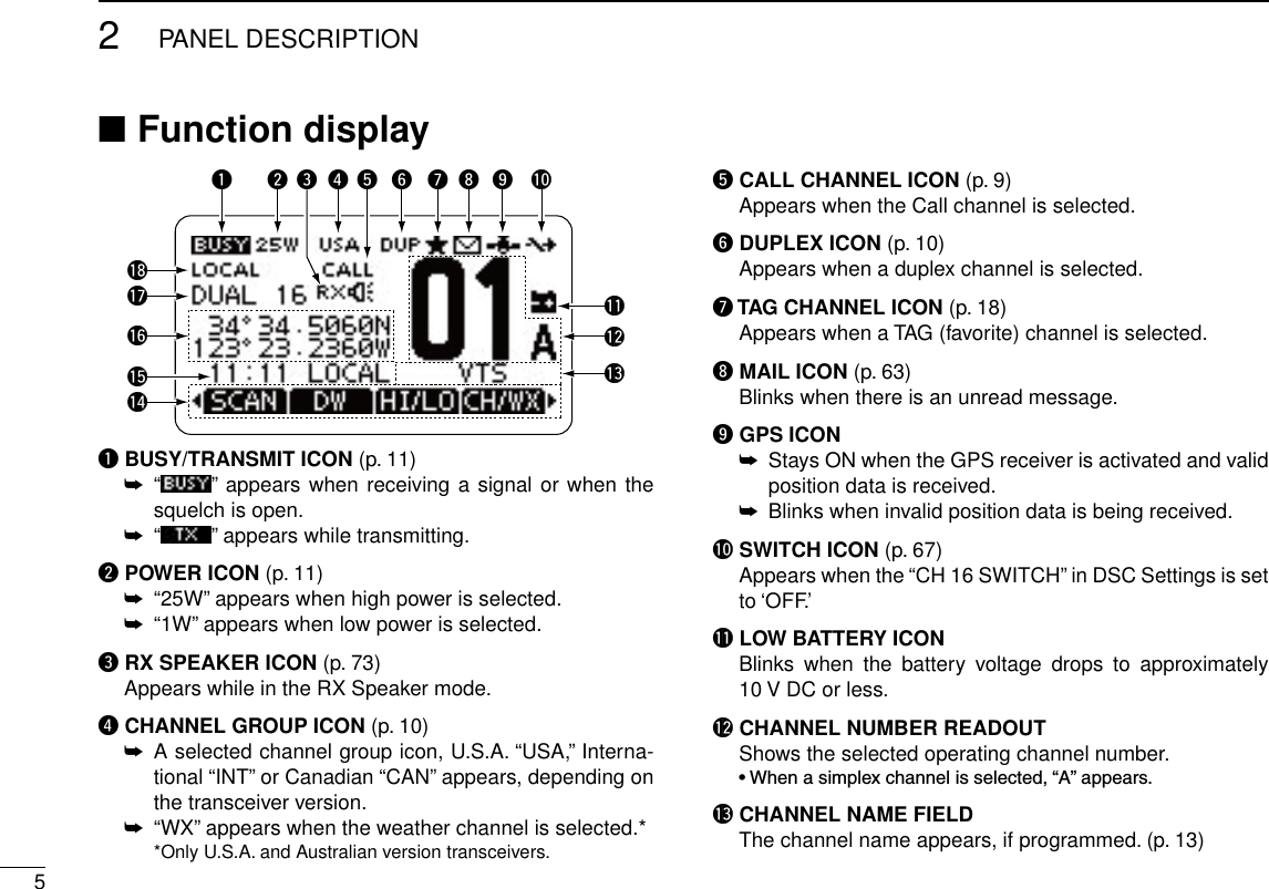
![New200172PANEL DESCRIPTIONSpeaker Microphone ■MicrophoneSpeakerwqeq PTT SWITCH [PTT] Hold down to transmit, release to receive. (p. 11)w CHANNEL UP/DOWN KEYS [Y]/[Z] Push either key to check TAG channels, Set mode set- ➥tings, and so on. (pp. 11, 75) Push either key to change scanning direction or manu- ➥ally resumes a scan. (p. 18)e TRANSMIT POWER KEY [HI/LO]Push to toggle the power high or low. (p. 11) ➥ •Somechannelsaresettoonlylowpower. While holding down [HI/LO], turn ON the power to turn ➥the Microphone Lock function ON or OFF. (p. 14)Softkey function ■Various functions can be assigned to the softkeys. When a key function is assigned, the key icon is displayed above the soft-key, as shown below. Consult your Icom dealer for details con-cerning which functions are preprogrammed into the keys.Softkey function selection D When “ ➥Ω” or “≈” is displayed beside the key icon, push-ing [Ω] or [≈] sequentially shows the previous or next key function that is assigned to the softkey.Push Push**Push this key to start and stop scan.The order of the key icons may differ, depending on the preprogramming.For Chinese version transceiver:•[ ] appears instead of [ ].•[ ] does not appear.](https://usermanual.wiki/ICOM-orporated/333800/User-Guide-1676007-Page-16.png)
 to turn ON the power. q •Threeshortbeepssound,and“NODSCMMSI”isdisplayed.Push [ENT] to start the MMSI code programming. w •Push[CLEAR]twicetocanceltheprogramming,andgotothenormal operating screen. In this case, the transceiver cannot make a DSC call. To program the MMSI code, turn OFF the power, then turn it ON again.Enter your MMSI code in the following manner: e •SelectadesirednumberusingDial,or[∫]/[√]/[Ω]/[≈]. •Push[ENT]orDialtosetit. •Tomovethecursor,selecteitherarrow,“←” or “→,” then push [ENT] or Dial.Repeat step r e to enter all 9 digits. After entering the 9 digit code, “FINISH” is automatically tselected, and then push [ENT] or Dial to set it.The “MMSI CONFIRMATION” screen is displayed. yEnter your MMSI code again for confirmation. u •Enterinthesamemannerasstepse through t. When your MMSI code programming is successfully com- ipleted, the screen as shown below is briefly displayed. •Afterthat,thenormaloperatingscreenisdisplayed.The programmed MMSI code can be checked in the MENU screen. (p. 76)](https://usermanual.wiki/ICOM-orporated/333800/User-Guide-1676007-Page-17.png)
![New20019New2001BASIC OPERATION49Channel selection ■Channel 16 DChannel 16 is the distress and safety channel. It is used for establishing initial contact with a station and for emergency communications. Channel 16 is monitored during both Du-alwatch and Tri-watch. While standing by, you must monitor Channel 16.Push [16/C] to select Channel 16. ➥ Push [CH/WX]* to return to the screen displayed before you ➥selected Channel 16, or push [∫](CH) or [√](CH) to select an operating channel. * [CHAN] appears only for Chinese version transceiver.Call channel DEach regular channel group has a separate leisure use Call channel. The Call channel is monitored during Tri-watch. The Call channels can be programmed, and are used to store your most often used channel in each channel group, for quick recall. (p. 13) Hold down [16/C] for 1 second to select the Call channel of ➥the selected channel group. •“CALL”andtheCallchannelnumberappear. •Eachchannelgrouphasanindependentcallchannelafterpro-gramming. (p. 13) Push [CH/WX]* to return to the screen displayed before you ➥selected Call channel, or push [∫](CH) or [√](CH) to select an operating channel. * [CHAN] appears only for Chinese version transceiver.](https://usermanual.wiki/ICOM-orporated/333800/User-Guide-1676007-Page-18.png)
![New2001104BASIC OPERATIONNew200112345678910111213141516Channel group selection DThere are preprogrammed U.S.A. channels, International channels and Canadian channels. These channel groups may be specified for the operating area.Push [MENU]. q Rotate Dial or push [ w∫]/[√] to select “Radio Settings,” and then push [ENT]. Rotate Dial or push [ e∫]/[√] to select “CHAN Group,” and then push [ENT]. Rotate Dial or push [ r∫]/[√] to select the desired channel group, and then push [ENT]. •U.S.A.(USA),International(INT)andCanadian(CAN)channelgroups can be selected.Push [EXIT] to exit the Menu screen. tPush [ y∫](CH) or [√](CH) to select a channel. •Pushing[Y]/[Z] on the microphone selects only TAG channels. •“DUP”appearswhenaduplexchannelisselected. •“A”appearswhenasimplexchannelisselected.When the International channel group is selected.Channel group icon appears](https://usermanual.wiki/ICOM-orporated/333800/User-Guide-1676007-Page-19.png)
![114BASIC OPERATIONNew2001Weather channels D (U.S.A. and Australian version transceiver only)The transceiver has 10 weather channels. These are used for monitoring broadcasts from NOAA (National Oceanographic and Atmospheric Administration.)The transceiver can automatically detect a weather alert tone on the selected weather channel or while scanning. (p. 17) Push [CH/WX] once or twice to select a weather channel. q •“WX”appearswhenaweatherchannelisselected. •“WX ” appears when the Weather Alert function is in turned ON. (p. 78)Push [ w∫•CH]or[√•CH]toselectachannel. •Pushing[Y]/[Z] on the microphone also selects a channel.When weather alert is OFF.When weather alert is ON.Receiving and transmitting ■CAUTION: Transmitting without an antenna will damage the transceiver.Hold down [PWR](Dial) to turn ON the power. q Set the audio and squelch levels. (p. 15) w First, open the squelch. Then, adjust the audio output ➥level. After that, adjust the squelch level until the noise just disappears. Change the channel group. (p. 10) e Push [ r∫](CH) or [√](CH) to select a channel. (pp. 9, 10) •Pushing[Y]/[Z] on the microphone also selects a channel. •Whenreceivingasignal,“ ” appears and audio is heard. •Furtheradjustmentofthevolumelevelmaybenecessary. Push [LO/DX] to turn the receive Attenuator function ON tor OFF, if necessary. •OnlyU.S.A.andAustralianversiontransceivers. •“LOCAL”appearswhenthereceiveAttenuatorfunctionisON. Push [HI/LO] to select the output power, if necessary. y •“25W”appearswhenhighpowerisselected,and“1W”appearswhen low power is selected. •Chooselowpowerforshortrangecommunications,choosehighpower for longer distance communications. •Somechannelsareforonlylowpower. Hold down [PTT] to transmit, then speak at your normal uvoice level. •“ ” appears. •Channel70cannotbeusedfortransmissionotherthanDSC.Release [PTT] to receive. i](https://usermanual.wiki/ICOM-orporated/333800/User-Guide-1676007-Page-20.png)
![124BASIC OPERATIONNew20011234567891011121314151612Information ✓The Noise Cancel function reduces random noise components in the transmit and/or receive signal. See page 80 for details.Simplex channels, 3, 21, 23, 61, 64, 81, 82 and 83 CANNOT be lawfully used by the general public in U.S.A. waters.IMPORTANT: To maximize the readability of your transmit-ted signal, pause a few seconds after pushing [PTT], hold the microphone 5 to 10 cm (2 to 4 inches) from your mouth and speak at a normal voice level.NOTE for the TOT (Time-out Timer) function ✓The TOT function inhibits continuous transmission beyond a preset time period after the transmission starts.10 seconds before transmission is cutoff, a beep sounds to indicate the transmission will be shut down and “TOT” appears in the channel name field. Transmission is not possible for 10 seconds after this shut down.Microphonet y qwiuryr](https://usermanual.wiki/ICOM-orporated/333800/User-Guide-1676007-Page-21.png)
![134BASIC OPERATIONCall channel programming ■You can program the Call channel with your most often-used channel in each channel group for quick recall. Select the desired channel group (INT, USA or CAN) to be qprogrammed. (p. 10) Hold down [16/C] for 1 second to select the Call channel of wthe selected channel group. •“CALL”andtheCallchannelnumberappear. Hold down [16/C] again for 3 seconds (until a long beep echanges to 2 short beeps) to enter the Call channel pro-gramming mode. Rotate Dial or push [ r∫](CH)/[√](CH) to select a channel. Push [ENT] to program the displayed channel as the Call tchannel. •Push[CLEAR]tocancel.Channel name programming ■Each channel can be assigned a unique alphanumeric ID of up to 10 characters.Capital letters, 0 to 9, some symbols (! " # $ % & ' ( ) * + , – . /[\]^_:;<=>?)andaspacecanbeinput.Push [ q∫](CH) or [√](CH) to select a channel. •First, cancel the Dualwatch,Tri-watchorScanfunction,if acti-vated. Push [NAME] to open the channel name programming wscreen. •Ablackboxisdisplayedontherstcharacter.Enter the desired channel name in the following manner: e •SelectadesiredcharacterusingDial,or[∫]/[√]/[Ω]/[≈]. •Push[ENT]tosetit. •Tomovethecursor,selecteitherarrow,“←” or “→,” then push [ENT]. •Select“SPACE,”thenpush[ENT]toinputaspace. •Select“DELETE,”thenpush[ENT]todeleteacharacter. •Push[CLEAR]tocancelandreturntothepreviousscreen.](https://usermanual.wiki/ICOM-orporated/333800/User-Guide-1676007-Page-22.png)
![144BASIC OPERATION12345678910111213141516Repeat step r e to input all characters. Push [ tΩ], [≈], [∫] or [√] to select “FINISH,” then push [ENT] to set the name and return to the previous screen.Microphone Lock function ■The Microphone Lock function electrically locks [∫], [√] and the [HI/LO] keys on the supplied microphone. This prevents accidental channel changes and function access. While holding down [HI/LO] on the microphone, hold down ➥[PWR](Dial) to turn ON the transceiver and turn the Micro-phone Lock function ON or OFF.[HI/LO][Y]/[Z]](https://usermanual.wiki/ICOM-orporated/333800/User-Guide-1676007-Page-23.png)
. Rotate [VOL/SQL](Dial), or push [VOL/SQL](Dial) one or qmore times to display the volume adjustment screen.Rotate [VOL/SQL](Dial) to adjust the volume level. w •Thetransceiverhas20volumelevelsandOFF. •Ifnokeyoperationisperformedforabout5seconds,thetrans-ceiver sets the selected volume level, and returns to the normal mode. Push [ENT] to set the level, and exit the volume adjust- ement mode. •Push[CLEAR]tocancel.The desired function can be assigned to Dial. See page 79 for details.Adjusting the squelch level ■The squelch level can be adjusted with [VOL/SQL](Dial).In order to receive signals properly, as well as for the scan to function effectively, the squelch must be adjusted to the proper level. Push [VOL/SQL](Dial) one or more times to display the qsquelch adjustment screen.Rotate [VOL/SQL](Dial) to adjust the squelch level. w •The transceiver has 11 squelch levels: OPEN is completelyopen; 10 is tight squelch; 1 is loose squelch. •Ifnokeyoperationisperformedforabout5seconds,thetrans-ceiver sets the selected squelch level, and returns to the normal mode. Push [ENT] to set the level, and exit the squelch adjust- ement mode. •Push[CLEAR]tocancel.The desired function can be assigned to Dial. See page 79 for details.](https://usermanual.wiki/ICOM-orporated/333800/User-Guide-1676007-Page-24.png)
![164BASIC OPERATION12345678910111213141516 Adjusting the display ■backlight levelThe function display and keys can be backlit for better visibil-ity under low light conditions.The backlight is adjustable in 7 levels and OFF.Depending on the preprogramming, the adjustment method differs, as described below. Push [BKLT] to show the backlight adjustment screen. Ro- ➥tate Dial to adjust the brightness of the LCD and key back-light, and then, push [ENT]. •Ifnokeyoperationisperformedforabout5seconds,thetransceiversets the selected backlight level, and returns to the normal mode.When the Backlight function is assigned to the [VOL/SQL](Dial): Push [VOL/SQL](Dial) one or more times to display the qbacklight adjustment screen. Rotate [VOL/SQL](Dial) to adjust the brightness of the wLCD and key backlight, and then, push [ENT].The desired function can be assigned to Dial. See page 79 for details. AquaQuake water draining ■functionThe AquaQuake water draining function clears water away from the speaker grill. Without this function, water may muffle the sound coming from the speaker. A buzzing sound is heard when this function is activated. While holding down [AQUA], the AquaQuake function is ➥activated to clear water away from the speaker grill. •Whileholdingdown[AQUA],alowbuzzingsoundstodrainwa-ter, regardless of the volume level setting. •The transceiver keys, except [DISTRESS], are disabled whilethe AquaQuake function is activated.When the AquaQuake function is activated.](https://usermanual.wiki/ICOM-orporated/333800/User-Guide-1676007-Page-25.png)
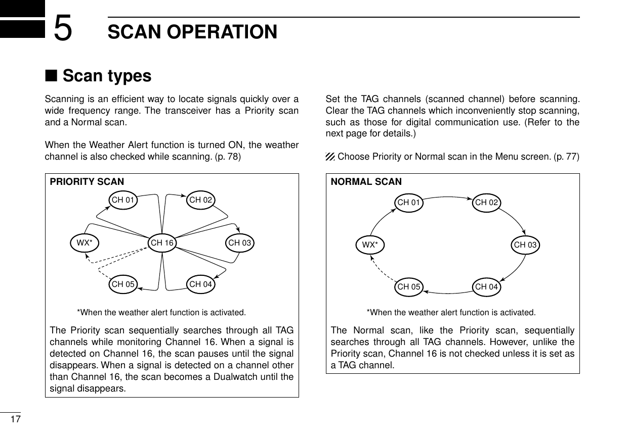
![185SCAN OPERATIONSetting TAG channels ■For more efficient scanning, add desired channels as TAG channels, or clear the TAG on unwanted channels. Channels that are not tagged will be skipped while scanning. TAG channels can be independently assigned to each chan-nel group (INT, USA, or CAN).Select the desired channel group. (p. q10)Select the desired channel to be set as a TAG channel. w Push [ e] to set the displayed channel as a TAG channel. •“” appears on the display. To cancel the TAG channel setting, repeat step r e. •“” disappears.Clearing (or setting) all tagged channels ✓Hold down [] for 3 seconds (until a long beep changes to 2 short beeps) to clear all TAG channel settings in the selected channel group.•RepeataboveproceduretosetallchannelsasTAGchannels.Starting a scan ■First, set the scan type (Priority or Normal scan) and scan resume timer in the Menu screen. (p. 77)Select the desired channel group. (p. q10)Set the TAG channels, as described to the left. wMake sure the squelch is closed to start a scan. ePush [SCAN] to start a Priority or Normal scan. r •“SCAN16”appearsduringaPriorityscan;“SCAN”appearsdur-ing a Normal scan. •Whenasignalisdetected,thescanpausesuntilthesignaldis-appears, or resumes after pausing 5 seconds, depending on the Set mode setting. (Channel 16 is still monitored during a Priority scan.) •Push[Y]/[Z] on either transceiver or microphone, to check the scanning TAG channels, change the scanning direction or man-ually resume the scan. •Abeeptonesoundsand“16”blinkswhenasignalisreceivedonChannel 16 during a Priority scan.To stop the scan, push [CLEAR] or repeat step t r.Scan starts. When a signal is received.Push[SCAN][Example]: Starting a Normal scan.12345678910111213141516](https://usermanual.wiki/ICOM-orporated/333800/User-Guide-1676007-Page-27.png)
 or [Z](CH) to select the desired operating channel. Push [DW] to start a Dualwatch or Tri-watch scan. e •“DUAL16”appearsduringDualwatch;“TRI16”appearsduringTri-watch. •AbeeptonesoundswhenasignalisreceivedonChannel16. To cancel Dualwatch or Tri-watch, push [DW] again. rDUALWATCH/TRI-WATCH SIMULATIONDualwatch Tri-watchCall channelCh 88Ch 16 Ch 88 Ch 16 Ch 88 Ch 9•IfasignalisreceivedonChannel16,DualwatchandTri-watch pause on Channel 16 until the signal disappears.•IfasignalisreceivedontheCallchannelduringTri-watch,Tri-watch becomes Dualwatch until the signal disap-pears.•TotransmitontheselectedchannelduringaDualwatchorTri-watch scan, hold down [PTT].[Example]: Operating Tri-watch on INT Channel 25.Tri-watch starts. Signal is received on Call channel.Tri-watch resumes after the signal disappears.Signal received on Channel 16 takes priority.](https://usermanual.wiki/ICOM-orporated/333800/User-Guide-1676007-Page-28.png)
![207DSC OPERATIONDSC address ID ■Programming Individual ID DA total of 100 DSC address IDs can be programmed and as-signed a name of up to 10 characters.Enter “INDIVIDUAL ID” in the DSC SETTINGS menu. qPush [ADD]. w •The“INDIVIDUALID”programscreenisdisplayed.Enter a desired individual ID in the following way: e •SelectadesirednumberusingDial,or[Y]/[Z]/[Ω]/[≈]. •Push[ENT]orDialtosetit. •Tomovethecursor,selecteitherarrow,“←” or “→,” then push [ENT] or Dial. The first digit is specified as ‘0’ for a Group ID.The first two digits are ‘0’ for any Coast station ID.Repeat step r e to enter all 9 digits.After entering the 9 digit code, push [ENT] or Dial to set it. t •TheIDnameprogrammingscreenisdisplayed.Enter a desired 10 digit ID name in the following way: y •SelectadesiredcharacterusingDial,or[Y]/[Z]/[Ω]/[≈]. •Push[ENT]orDialtosetit. •Tomovethecursor,selecteitherarrow,“←” or “→,” then push [ENT] or Dial. •Push[123]then[!$?]then[ABC]toselectacharactergroup. After entering the ID name, select “FINISH” using Dial, or u[Y]/[Z]/[Ω]/[≈], then push [ENT] or Dial to program it. •The“INDIVIDUALID”listscreenisdisplayed.Push [MENU] to exit the MENU screen. i12345678910111213141516 MENU ➪ DSC Settings ➪ Individual ID (Push [MENU]) (Rotate Dial, then push [ENT].)](https://usermanual.wiki/ICOM-orporated/333800/User-Guide-1676007-Page-29.png)
![217DSC OPERATIONProgramming Group ID DEnter “GROUP ID” in the DSC SETTINGS menu. qPush [ADD]. w •The“GROUPID”programscreenisdisplayed.Enter a desired group ID in the following way: e •SelectadesirednumberusingDial,or[Y]/[Z]/[Ω]/[≈]. •Push[ENT]orDialtosetit. •Tomovethecursor,selecteitherarrow,“←” or “→,” then push [ENT] or Dial. The first digit is fixed as ‘0’ for a Group ID.The first two digits are ‘0’ for any Coast station ID.Repeat step r e to input the specific 9 digits group code. After entering the 9 digit code, push [ENT] or Dial to set it. t •TheGroupIDnameprogrammingscreenisdisplayed.Enter a desired 10 digit ID name in the following way: y •SelectadesiredcharacterusingDial,or[Y]/[Z]/[Ω]/[≈]. •Push[ENT]orDialtosetit. •Tomovethecursor,selecteitherarrow,“←” or “→,” then push [ENT] or Dial. •Push[123],[!$?]or[ABC]toselectacharactergroup. After entering the ID name, select “FINISH” using Dial, or u[Y]/[Z]/[Ω]/[≈], then push [ENT] or Dial to program it. •The“GROUPID”listscreenisdisplayed.Push [MENU] to exit the MENU screen. i MENU ➪ DSC Settings ➪ Group ID (Push [MENU]) (Rotate Dial, then push [ENT].)](https://usermanual.wiki/ICOM-orporated/333800/User-Guide-1676007-Page-30.png)
![227DSC OPERATIONDeleting Individual/Group ID D Enter “INDIVIDUAL ID” or “GROUP ID” in the DSC SET- qTINGS menu. •WhennoaddressIDisprogrammed,“NoID”isdisplayed.Inthiscase, push [MENU] to exit the MENU screen. Rotate Dial or push [ wY]/[Z] to select a desired ID name, then push [DEL]. Push [OK] to delete the ID, and return to the “INDIVIDUAL eID” or “GROUP ID” list screen. •Push[CANCEL]tocancelit.Push [MENU] to exit the MENU screen. r12345678910111213141516 MENU ➪ DSC Settings ➪ Individual ID/Group ID (Push [MENU]) (Rotate Dial, then push [ENT].)](https://usermanual.wiki/ICOM-orporated/333800/User-Guide-1676007-Page-31.png)
![237DSC OPERATIONA Distress call should include the ship’s position and time. If no GPS is connected, your position and UTC (Universal Time Coordinated) time should be manually input. They are auto-matically included when a GPS receiver compatible with the NMEA0183 ver. 2.0 or 3.01 format is connected.•ManualprogrammingisdisabledwhenaGPSreceiverisconnected.•Manuallyprogrammedpositionandtimewillbeheldforonly 23.5 hours.Enter “POSITION INPUT” in the DSC SETTINGS menu. q Edit your latitude and longitude position using Dial, or [ wY]/[Z]/[Ω]/[≈]. •SelectadesirednumberusingDial,or[Y]/[Z]/[Ω]/[≈]. •Push[ENT]orDialtosetit. •Tomovethecursor,selecteitherarrow,“←” or “→,” then push [ENT] or Dial. •SelectN(Northlatitude)orS(Southlatitude)whenthecursorison the ‘N’ or ‘S’ position. •SelectW(Westlongitude)orE(Eastlongitude)whenthecursoris on the ‘W’ or ‘E’ position.After entering the position, push [ENT] to program it. e The UTC time programming screen is displayed, enter the rUTC time in the following way: •SelectadesirednumberusingDial,or[Y]/[Z]/[Ω]/[≈]. •Push[ENT]orDialtosetit. •Tomovethecursor,selecteitherarrow,“←” or “→,” then push [ENT] or Dial. Push [ENT] or Dial to program your position and time. t •Returntothe“DSCSETTING”screen.Position and time programming ■ MENU ➪ DSC Settings ➪ Position Input (Push [MENU]) (Rotate Dial, then push [ENT].)](https://usermanual.wiki/ICOM-orporated/333800/User-Guide-1676007-Page-32.png)
![247DSC OPERATION12345678910111213141516Distress call ■A Distress call should be transmitted if, in the opinion of the Master, the ship or a person is in distress and requires im-mediate assistance.NEVER MAKE A DISTRESS CALL IF YOUR SHIP OR A PERSON IS NOT IN AN EMERGENCY. A DISTRESS CALL SHOULD BE MADE ONLY WHEN IMMEDIATE HELP IS NEEDED.Simple call DConfirm no Distress call is being received. q While lifting up the key cover, hold down [DISTRESS] for 3 wseconds to transmit the Distress call. •Whileholdingdown[DISTRESS],countdownbeepssoundandboth the key and display backlighting blink. •DSC channel (Channel 70) is automatically selected and theDistress call is transmitted. After transmitting the call, the transceiver waits for an ac- eknowledgment call. •The Distress call is automatically transmitted every 3.5 to 4.5minutes, until an acknowledgement is received (‘Call repeat’ mode), or DSC Cancel call is made. (p. 27) •Push[RESEND]tomanuallytransmittheDistressrepeatcall. •Push [Ω]/[≈] then push [INFO] to display the transmitted Dis-tress call information. •Push[Ω]/[≈] then push [PAUSE] to pause the ‘Call repeat’ mode, push [RESUME] to resume it. After receiving the acknowledgment, push [ALARM OFF] rthen reply using the microphone.A distress alert default contains: ➥ •Natureofdistress :Undesignateddistress •Positioninformation:The latest GPS or manual input positionis held for 23.5 hours, or until the power is turned OFF.](https://usermanual.wiki/ICOM-orporated/333800/User-Guide-1676007-Page-33.png)
![257DSC OPERATIONRegular call DThe nature of the Distress call should be included in the Dis-tress call.Enter “DISTRESS CALL” in the DSC CALLS menu. q Select the nature of the distress using Dial or [ wY]/[Z], then push Dial or [ENT]. •‘Undesignated,’‘Fire,Explosion,’‘Flooding,’‘Collision,’‘Grounding,’‘Capsizing,’ ‘Sinking,’ ‘Adrift,’ ‘Abandoning ship,’ ‘Piracy’ or ‘Man Overboard’ is selectable. •Thenatureofthedistressisstoredfor10minutesafteraselec-tion is made.The Distress call confirmation screen is displayed. e •RotateDialorpush[Y]/[Z] to see the hidden lines. Hold down [DISTRESS] for 3 seconds to transmit the Dis- rtress call. •Whileholdingdown[DISTRESS],countdownbeepssoundandboth the key and display backlighting blink. •Theselectednatureofthedistressisstoredfor10minutes. MENU ➪ DSC Calls ➪ Distress Call (Push [MENU]) (Rotate Dial, then push [ENT].)](https://usermanual.wiki/ICOM-orporated/333800/User-Guide-1676007-Page-34.png)
![267DSC OPERATION12345678910111213141516 After transmitting the call, the transceiver waits for an ac- tknowledgment call. •The Distress call is automatically transmitted every 3.5 to 4.5minutes, until an acknowledgement is received (‘Call repeat’ mode), or DSC cancel call is made. (p. 27) •Push[RESEND]tomanuallytransmittheDistressrepeatcall. •Push [Ω]/[≈] then push [INFO] to display the transmitted Dis-tress call information. •Push[Ω]/[≈] then push [PAUSE] to pause the ‘Call repeat’ mode, push [RESUME] to resume it. After receiving an acknowledgment call, push [ALARM yOFF] then reply using the microphone.A distress alert contains: ➥ •Natureofdistress :Selectedinstepw. •Positioninformation:The latest GPS or manual input positionis held for 23.5 hours, or until the power is turned OFF.When no GPS receiver is connected, and both position and time have been manually programmed, the screen as shown below appears. Edit your latitude and longitude po-sition and UTC time as follows: Push [CHG], then edit your latitude and longitude posi- ➥tion and UTC time. •SelectadesirednumberusingDial,or[Y]/[Z]/[Ω]/[≈]. •Push[ENT]orDialtosetit. •Tomovethecursor,selecteitherarrow,“←” or “→,” then push [ENT] or Dial. •SelectN(Northlatitude)orS(Southlatitude)whenthecursoris on the ‘N’ or ‘S’ position. •SelectW(Westlongitude)orE(Eastlongitude)whenthecur-sor is on the ‘W’ or ‘E’ position.](https://usermanual.wiki/ICOM-orporated/333800/User-Guide-1676007-Page-35.png)
![277DSC OPERATIONDistress cancel call D While waiting for an acknowledgment call, push [CAN- qCEL].Push [CONTINUE]. w •Push[BACK]toreturntowaitingforanacknowledgementcall.Push [FINISH]. e •Push[EXIT]toreturntowaitingforanacknowledgementcall.The Distress cancel call is transmitted. rChannel 16 is automatically selected. t •Reportyoursituationusingthemicrophone. •Afterthereport, push[EXIT]toreturn tothenormaloperatingmode.](https://usermanual.wiki/ICOM-orporated/333800/User-Guide-1676007-Page-36.png)
![287DSC OPERATION12345678910111213141516Transmitting DSC calls ■To ensure correct operation of the DSC function, make sure you correctly set the CH70 SQL LEVEL. (p. 69)Transmitting an individual call DThe Individual call function allows you to transmit a DSC sig-nal to only a specific station.Enter “INDIVIDUAL CALL” in the DSC CALLS menu. q MENU ➪ DSC Calls ➪ Individual Call (Push [MENU]) (Rotate Dial, then push [ENT].) Select the desired preprogrammed individual address, or w“Manual Input,” using Dial or [Y]/[Z], then push Dial or [ENT]. •TheIDcodefortheIndividualcallcanbesetrst.(p.20) •When“ManualInput”isselected,setadesired9digitMMSIIDcode for the individual you wish to call. About Manual Inputting:Enter a desired individual ID in the following way:•SelectadesirednumberusingDial,or[Y]/[Z]/[Ω]/[≈].•Push[ENT]orDialtosetit.•Tomovethecursor,selecteitherarrow,“←” or “→,” then push [ENT] or Dial.•Therstdigitisspeciedas‘0’foraGroupID.IfaGroupIDisentered, an error beep sounds after pushing [FINISH].•Thersttwodigitsare‘0’foranycoaststationID. Select Routine, Safety or Urgency as the desired call type eusing Dial or [Y]/[Z], then push [ENT].NOTE: When a coast station is selected in step w, the voice channel is automatically specified by the coast sta-tion. Therefore, skip step r and go directly to step t. + Continued on the next page.](https://usermanual.wiki/ICOM-orporated/333800/User-Guide-1676007-Page-37.png)
/[Z](CH), then push [ENT]. •Intershipchannelsarealreadypresetintothetransceiverintherecommended order.A confirmation screen appears. t •Conrmthecallcontents.Push [CALL] to transmit the Individual call. y •IfChannel70isbusy,thetransceiverstandsbyuntilthechannelbecomes clear. Standby on Channel 70 until an acknowledgement is re- uceived. When the acknowledgement ‘Able to comply’ is received, ibeeps sound and the screen below is displayed. Push [ALARM OFF] to stop the beeps and then select the intership channel specified in step r. •Adifferentintership channel willbeselected if thestationyoucalled cannot use the channel. •Replyusingthemicrophone.Andgotostepo.](https://usermanual.wiki/ICOM-orporated/333800/User-Guide-1676007-Page-38.png)
![307DSC OPERATION12345678910111213141516 Or, when the acknowledgement ‘Unable to comply’ is re-ceived, beeps sound and the screen below is displayed. Push [ALARM OFF] to stop the beeps. Then push [EXIT] to return to the operating channel (before you entered the MENU screen). After communicating, push [EXIT] to return to the normal ooperating mode.Convenient! ✓When the optional MA-500TR c l a s s b a i s t r a n s p o n d e r is connected to your transceiver, you can transmit individual DSC calls to selected AIS targets on the transponder without needing to enter the target’s MMSI code.See pages 70 and 84 for more details.Transmitting an Individual Acknowledgement DWhen receiving an Individual call, you can transmit an ac-knowledgement (‘Able to Comply,’ ‘Propose New Channel’ or ‘Unable to Comply’) by using the on-screen prompts (Quick ACK.) Also, you can send an acknowledgement through the MENU system (Man ual ACK.)Quick ACK: When an Individual call is received, beeps sound and the qscreen below is displayed. Push [ALARM OFF] to stop the beeps.Push [ACK]. w + Continued on the next page.](https://usermanual.wiki/ICOM-orporated/333800/User-Guide-1676007-Page-39.png)
![317DSC OPERATIONTransmitting an Individual Acknowledgement (continued) DSelect one of three options, then push [ENT]. e •AbletoComply :Makeanacknowledgmentcallwithoutany changes. •UnabletoComply :Youcannotmakeacommunication. The Acknowledgement call (‘Unable to Comply’) can be automatically trans-mitted, if set. See page 66 for details. •ProposeNewChannel :You can make an acknowledgementcall, but you specify the intership chan-nel. Select a desired intership channel, using Dial, or [Y](CH)/[Z](CH), then push [ENT].The Individual ACK confirmation screen is displayed. r Push [CALL] to transmit an acknowledgement call.The screens shown below are displayed. tReply to the call using the microphone. yPush [EXIT] to return to the normal operating mode. u](https://usermanual.wiki/ICOM-orporated/333800/User-Guide-1676007-Page-40.png)
![327DSC OPERATION12345678910111213141516Manual ACK:Enter “INDIVIDUAL ACK” in the DSC CALLS menu. q MENU ➪ DSC Calls ➪ Individual ACK (Push [MENU]) (Rotate Dial, then push [ENT].) •WhennoIndividualcallhasbeenreceived,“IndividualACK”itemwill not be displayed. Select a desired individual address or ID code to reply to, wusing Dial or [Y]/[Z], then push [ENT]. Perform steps e e to u, as described in “Quick ACK:,” be-ginning on the previous page.Transmitting a Group call DThe Group call function allows you to transmit a DSC signal to only a specific group.Enter “GROUP CALL” in the DSC CALLS menu. q MENU ➪ DSC Calls ➪ Group Call (Push [MENU]) (Rotate Dial, then push [ENT].) Select the desired preprogrammed group address or “Man- wual Input,” using Dial or [Y]/[Z], then push Dial or [ENT]. •TheIDcodefortheGroupcallcanbesetrst.(p.21) •When“ManualInput”isselected,setthe8digitIDcodeforthegroup you wish to call. Select a desired intership channel using Dial or [ eY](CH)/[Z](CH), then push [ENT]. •Intershipchannelsarealreadypresetintothetransceiverintherecommended order. + Continued on the next page.](https://usermanual.wiki/ICOM-orporated/333800/User-Guide-1676007-Page-41.png)
![337DSC OPERATIONTransmitting a Group call (continued) DAbout Manual Inputting:Enter a desired group ID in the following way:•SelectadesirednumberusingDial,or[Y]/[Z]/[Ω]/[≈].•Push[ENT]orDialtosetit.•Tomovethecursor,selecteitherarrow,“←” or “→,” then push [ENT] or Dial.•Therstdigitisspeciedas‘0’foraGroupID.•Thersttwodigitsare‘0’foranyCoaststationID.A confirmation screen appears. r •Conrmthecallcontents. Push [CALL] to transmit the Group call. t •IfChannel70isbusy,thetransceiverstandsbyuntilthechannelbecomes clear. After the Group call has been transmitted, the following yscreen is displayed.Announce the information using the microphone. u After the announcement, push [EXIT] to return to the nor- imal operating mode.](https://usermanual.wiki/ICOM-orporated/333800/User-Guide-1676007-Page-42.png)
![347DSC OPERATION12345678910111213141516Transmitting an All Ships call DAll ships, that have DSC transceiver, use Channel 70 as their ‘listening channel.’ When you want to announce a message to these ships within range, use the ‘All Ships Call’ function.Enter “ALL SHIPS CALL” in the DSC CALLS menu. q MENU ➪ DSC Calls ➪ All Ships Call (Push [MENU]) (Rotate Dial, then push [ENT].) Select a desired category, using Dial or [ wY]/[Z], then push Dial or [ENT]. •The selectable category may differ, depending on the pro-grammed setting. Ask your dealer for the selectable categories. Select a desired traffic channel, using Dial or [ eY]/[Z], then push Dial or [ENT]. •Theselectedchannelisdisplayed.A confirmation screen appears. r •Conrmthecallcontents.Push [CALL] to transmit the All Ships call. t •IfChannel70isbusy,thetransceiverstandsbyuntilthechannelbecomes clear. After the All Ships call has been transmitted, the following yscreen is displayed.Announce the message using the microphone. u After the announcement, push [EXIT] to return to the nor- imal operating mode.](https://usermanual.wiki/ICOM-orporated/333800/User-Guide-1676007-Page-43.png)
![357DSC OPERATIONTransmitting a Position Request Call D (U.S.A. and Australian version transceiver only)Transmit a Position Request Call when you want to know a specific ship’s current position, etc.Enter “POSITION REQUEST” in the DSC CALLS menu. q MENU ➪ DSC Calls ➪ Position Request (Push [MENU]) (Rotate Dial, then push [ENT].) Select the desired preprogrammed individual address, or w“Manual Input,” using Dial or [Y]/[Z], then push Dial or [ENT]. •TheIDcodeforthePositionRequestCallcanbesetrst.(p.20) •When“ManualInput”isselected,setadesired9digitMMSIIDcode for the individual you wish to call.About Manual Inputting:Enter a desired individual ID in the following way:•SelectadesirednumberusingDial,or[Y]/[Z]/[Ω]/[≈].•Push[ENT]orDialtosetit.•Tomovethecursor,selecteitherarrow,“←” or “→,” then push [ENT] or Dial.•Therstdigitisspeciedas‘0’foraGroupID.IfaGroupIDisentered, an error beep sounds after pushing [FINISH].•Thersttwodigitsare‘0’foranycoaststationID.A confirmation screen appears. e •Conrmthecallcontents.](https://usermanual.wiki/ICOM-orporated/333800/User-Guide-1676007-Page-44.png)
![367DSC OPERATION12345678910111213141516Push [CALL] to transmit the Position Request Call. r •IfChannel70isbusy,thetransceiverstandsbyuntilthechannelbecomes clear. After the Position Request Call has been transmitted, the tfollowing screen is displayed. When the acknowledgement call is received, beeps sound yand the following screen is displayed. Push [ALARM OFF] to stop the beeps, and then the screen uas shown below is displayed.Push [EXIT] to return to the normal operating mode. i](https://usermanual.wiki/ICOM-orporated/333800/User-Guide-1676007-Page-45.png)
![377DSC OPERATIONTransmitting a Position Report Call D (U.S.A. and Australian version transceiver only)Transmit a Position Report Call when you want to announce your own position to a specific ship and receive an answer back.Enter “POSITION REPORT” in the DSC CALLS menu. q MENU ➪ DSC Calls ➪ Position Report (Push [MENU]) (Rotate Dial, then push [ENT].) Select the desired preprogrammed individual address, or w“Manual Input,” using Dial or [Y]/[Z], then push Dial or [ENT]. •TheIDcodefortheIndividualcallcanbesetrst.(p.20) •When“ManualInput”isselected,setadesired9digitMMSIIDcode for the individual you wish to call. About Manual Inputting:Enter a desired individual ID in the following way:•SelectadesirednumberusingDial,or[Y]/[Z]/[Ω]/[≈].•Push[ENT]orDialtosetit.•Tomovethecursor,selecteitherarrow,“←” or “→,” then push [ENT] or Dial.•Therstdigitisspeciedas‘0’foraGroupID.IfaGroupIDisentered, an error beep sounds after pushing [FINISH].•Thersttwodigitsare‘0’foranycoaststationID.A confirmation screen appears. e •Conrmthecallcontents.](https://usermanual.wiki/ICOM-orporated/333800/User-Guide-1676007-Page-46.png)
![387DSC OPERATION12345678910111213141516Push [CALL] to transmit the Position Report Call. r •IfChannel70isbusy,thetransceiverstandsbyuntilthechannelbecomes clear. After the Position Report Call has been transmitted, the ttransceiver automatically returns to the normal operating mode.When no GPS receiver is connected, and both position and time have been manually programmed, the screen shown below appears. Edit your latitude and longitude position and UTC time as follows: Push [CHG], then edit your latitude and longitude position ➥and UTC time. •SelectadesirednumberusingDial,or[Y]/[Z]/[Ω]/[≈]. •Push[ENT]orDialtosetit. •Tomovethecursor,selecteitherarrow,“←” or “→,” then push [ENT] or Dial. •SelectN(Northlatitude)orS(Southlatitude)whenthecursoris on the ‘N’ or ‘S’ position. •SelectW(Westlongitude)orE(Eastlongitude)whenthecur-sor is on the ‘W’ or ‘E’ position.](https://usermanual.wiki/ICOM-orporated/333800/User-Guide-1676007-Page-47.png)
![397DSC OPERATIONTransmitting a Polling Request Call D (U.S.A. and Australian version transceiver only)Transmit a Polling Request Call when you want to know a specific vessel is in the communication area, or not.Enter “POLLING REQUEST” in the DSC CALLS menu. q MENU ➪ DSC Calls ➪ Polling Request (Push [MENU]) (Rotate Dial, then push [ENT].) Select the desired preprogrammed individual address, or w“Manual Input,” using Dial or [Y]/[Z], then push Dial or [ENT]. •TheIDcodefortheIndividualcallcanbesetrst.(p.20) •When“ManualInput”isselected,setadesired9digitMMSIIDcode for the individual you wish to call. About Manual Inputting:Enter a desired individual ID in the following way:•SelectadesirednumberusingDial,or[Y]/[Z]/[Ω]/[≈].•Push[ENT]orDialtosetit.•Tomovethecursor,selecteitherarrow,“←” or “→,” then push [ENT] or Dial.•Therstdigitisspeciedas‘0’foraGroupID.IfaGroupIDisentered, an error beep sounds after pushing [FINISH].•Thersttwodigitsare‘0’foranycoaststationID.A confirmation screen appears. e •Conrmthecallcontents.](https://usermanual.wiki/ICOM-orporated/333800/User-Guide-1676007-Page-48.png)
![407DSC OPERATION12345678910111213141516Push [CALL] to transmit the Polling Request Call. r •IfChannel70isbusy,thetransceiverstandsbyuntilthechannelbecomes clear. After the Polling Request Call has been transmitted, the tfollowing screen is displayed. When the acknowledgement call is received, beeps sound yand the following screen is displayed. Push [ALARM OFF] to stop the beeps, and then the screen uas shown below is displayed.Push [EXIT] to return to the normal operating mode. i](https://usermanual.wiki/ICOM-orporated/333800/User-Guide-1676007-Page-49.png)
![417DSC OPERATIONTransmitting a Test call DTesting on the exclusive DSC distress and safety calling chan-nels should be avoided as much as possible. When testing on a distress/safety channel is unavoidable, you should indicate that these are test transmissions. Normally the test call would require no further communica-tions between the two stations involved.Enter “TEST CALL” in the DSC CALLS menu. q MENU ➪ DSC Calls ➪ Test Call (Push [MENU]) (Rotate Dial, then push [ENT].) Select a desired preprogrammed individual address, or w“Manual Input,” then push Dial or [ENT]. •TheIDcodefortheIndividualcallcanbesetrst.(p.20) •When“ManualInput”isselected,setthe9digitMMSIIDcodeforthe individual you wish to call.About Manual Inputting:Enter a desired address ID in the following way:•SelectadesirednumberusingDial,or[Y]/[Z]/[Ω]/[≈].•Push[ENT]orDialtosetit.•Tomovethecursor,selecteitherarrow,“←” or “→,” then push [ENT] or Dial.•Therstdigitisspeciedas‘0’foraGroupID.IfaGroupIDisentered, an error beep sounds after pushing [FINISH].•Thersttwodigitsare‘0’foranyCoaststationID.A confirmation screen appears. e •Conrmthecallcontents.](https://usermanual.wiki/ICOM-orporated/333800/User-Guide-1676007-Page-50.png)
![427DSC OPERATION12345678910111213141516Push [CALL] to transmit the Test call. r •IfChannel70isbusy,thetransceiverstandsbyuntilthechannelbecomes clear. After the Test call has been transmitted, the following tscreen is displayed. When the acknowledgement call is received, beeps sound yand the following screen is displayed. Push [ALARM OFF] to stop the beeps, and then the screen uas shown below is displayed.Push [EXIT] to return to the normal operating mode. i](https://usermanual.wiki/ICOM-orporated/333800/User-Guide-1676007-Page-51.png)
![437DSC OPERATIONNew2001Transmitting a Test Acknowledgement call DWhen the “TEST ACK” in DSC settings is set to ‘Auto TX’ (p. 66), the transceiver automatically transmits a reply call when receiving a Test call.Quick ACK: When a Test call is received, beeps sound and the screen qshown below is displayed. Push [ALARM OFF] to stop the beeps.Push [ACK]. w •Push[INFO]todisplaytheTestcallinformation. Push [BACK] to return to the previous screen, or push [ACK].The Test ACK confirmation screen is displayed. e Push [CALL] to transmit the acknowledgement call. While transmitting the acknowledgement call, the screen rshown below is displayed, and then returns to the normal operating mode.](https://usermanual.wiki/ICOM-orporated/333800/User-Guide-1676007-Page-52.png)
![447DSC OPERATIONNew200112345678910111213141516Manual ACK:Enter “TEST ACK” in the DSC CALLS menu. q MENU ➪ DSC Calls ➪ Test ACK (Push [MENU]) (Rotate Dial, then push [ENT].) •IfnoTestcallhasbeenreceived,the“TESTACK”itemwillnotbe displayed. Select a desired Test call to reply to, using Dial or [ wY]/[Z], then push Dial or [ENT].The Test ACK confirmation screen is displayed. e Push [CALL] to transmit the acknowledgement call. While transmitting the acknowledgement call, the screen rshown below is displayed, and then returns to the normal operating mode.](https://usermanual.wiki/ICOM-orporated/333800/User-Guide-1676007-Page-53.png)
![457DSC OPERATIONNew2001Transmitting a Position Reply call DTransmit a Position Reply call when a Position Request call is received.When the “POSITION ACK” in DSC Settings is set to ‘Auto TX’ (p. 66), the transceiver automatically transmits a reply call when receiving a Position Request call.Quick Reply: When a Position Request call is received, beeps sound qand the screen shown below is displayed. Push [ALARM OFF] to stop the beeps.Push [ACK]. w •Push[INFO]todisplaythePositionRequestcallinformation. Push [BACK] to return to the previous screen, or push [ACK].The Position Reply confirmation screen is displayed. e Push [CALL] to transmit the reply call. While transmitting the reply call, the screen shown below ris displayed, and then returns to the normal operating mode.](https://usermanual.wiki/ICOM-orporated/333800/User-Guide-1676007-Page-54.png)
![467DSC OPERATIONNew200112345678910111213141516Manual Reply:Enter “POSITION REPLY” in the DSC CALLS menu. q MENU ➪ DSC Calls ➪ Position Reply (Push [MENU]) (Rotate Dial, then push [ENT].) •IfnoPositionRequestcallhasbeenreceived,the“POSITIONREPLY” item will not be displayed. Select a desired Position Request call to reply to, using wDial or [Y]/[Z], then push Dial or [ENT].The Position Reply call confirmation screen is displayed. e Push [CALL] to transmit the acknowledgement call. While transmitting the reply call, the screen shown below ris displayed, and then returns to the normal operating mode.When no GPS receiver is connected, and both position and time have been manually programmed, the screen shown below appears. Edit your latitude and longitude position and UTC time as follows: Push [CHG], then edit your latitude and longitude position ➥and UTC time. •SelectadesirednumberusingDial,or[Y]/[Z]/[Ω]/[≈]. •Push[ENT]orDialtosetit. •Tomovethecursor,selecteitherarrow,“←” or “→,” then push [ENT] or Dial. •SelectN(Northlatitude)orS(Southlatitude)whenthecursoris on the ‘N’ or ‘S’ position. •SelectW(Westlongitude)orE(Eastlongitude)whenthecur-sor is on the ‘W’ or ‘E’ position.](https://usermanual.wiki/ICOM-orporated/333800/User-Guide-1676007-Page-55.png)
![477DSC OPERATIONNew2001Transmitting a Position Report Reply call DTransmit a Position Report Reply call when a Position Report Request call is received.Quick Reply: When a Position Report Request call is received, beeps qsound and the screen as shown below is displayed. Push [ALARM OFF] to stop the beeps.Push [ACK]. w •Push[INFO]todisplaythePositionReportRequestcallinforma-tion. Push [BACK] to return to the previous screen, or push [ACK]. The Position Report Reply confirmation screen is dis- eplayed. Push [CALL] to transmit the reply call. While transmitting the reply call, the screen shown below ris displayed, and then returns to the normal operating mode.](https://usermanual.wiki/ICOM-orporated/333800/User-Guide-1676007-Page-56.png)
![487DSC OPERATIONNew200112345678910111213141516Manual Reply: Enter “POSITION REPORT REPLY” in the DSC CALLS qmenu. MENU ➪ DSC Calls ➪ Position Report Reply (Push [MENU]) (Rotate Dial, then push [ENT].) •IfnoPositionReportRequestcallhasbeenreceived,the“POSI-TION REPORT REPLY” item will not be displayed. Select a desired Position Report Request call to reply to, wusing Dial or [Y]/[Z], then push Dial or [ENT]. The Position Report Reply call confirmation screen is dis- eplayed. Push [CALL] to transmit the acknowledgement call. While transmitting the reply call, the screen shown below ris displayed, and then returns to the normal operating mode.](https://usermanual.wiki/ICOM-orporated/333800/User-Guide-1676007-Page-57.png)
![497DSC OPERATIONNew2001Transmitting a Polling Reply call DTransmit a Polling Reply call when a Polling Request call is received.When the “POSITION ACK” in DSC Settings is set to ‘Auto TX’ (p. 66), the transceiver automatically transmits a reply call when receiving a Polling Request call.Quick Reply: When a Polling Request call is received, beeps sound and qthe screen as shown below is displayed. Push [ALARM OFF] to stop the beeps.Push [ACK]. w •Push[INFO]todisplaythePollingRequestcallinformation. Push [BACK] to return to the previous screen, or push [ACK].The Polling Reply confirmation screen is displayed. e Push [CALL] to transmit the reply call. While transmitting the reply call, the screen shown below ris displayed, and then returns to the normal operating mode.](https://usermanual.wiki/ICOM-orporated/333800/User-Guide-1676007-Page-58.png)
![507DSC OPERATIONNew200112345678910111213141516Manual Reply:Enter “POLLING REPLY” in the DSC CALLS menu. q MENU ➪ DSC Calls ➪ Polling Reply (Push [MENU]) (Rotate Dial, then push [ENT].) •IfnoPollingRequestcallhasbeenreceived,the“POLLINGRE-PLY” item will not be displayed. Select a desired Polling Request call to be replied, using wDial or [Y]/[Z], then push Dial or [ENT]. eThe Polling Reply call confirmation screen is displayed. Push [CALL] to transmit the acknowledgement call. While transmitting the reply call, the screen shown below ris displayed, and then returns to the normal operating mode.](https://usermanual.wiki/ICOM-orporated/333800/User-Guide-1676007-Page-59.png)
![517DSC OPERATIONNew2001 New2001Receiving DSC calls ■Receiving a Distress Call DWhen a Distress Call is received: The emergency alarm sounds. ➥ “RCVD DISTRESS” pops up and the LCD backlight ➥blinks. Push [ALARM OFF] to stop the alarm and the blinking qbacklight. Push a softkey to select your desired action. w [IGN] ➥Push to return to the normal operating mode. •ThetransceiverexitstheDSCmode. •Bypushing[PTT],thetransceiveralsoexitstheDSCmode. •“ ” continues to blink and the Call is stored in the Received Call Log. [INFO] ➥Push to display the Received call information. (p. 64) [ACPT] Push to accept the call. ➥ And then, push [CH 16] to switch the operating channel to Channel 16, and then monitor it, as a coast station may require assistance. •Ifyouhaven’tpushed[CH16]within10seconds,theoperat-ing channel automatically switches to Channel 16. (p. 67)Push](https://usermanual.wiki/ICOM-orporated/333800/User-Guide-1676007-Page-60.png)
![New2001527DSC OPERATIONNew200112345678910111213141516Receiving a Distress Acknowledgement DWhen a Distress Acknowledgement sent to another ship is received:➥ The emergency alarm sounds.➥ “RCVD DISTRESS ACK” pops up and the LCD backlight blinks. Push [ALARM OFF] to stop the alarm and the blinking qbacklight. Push a softkey to select your desired action. w [IGN] ➥Push to return to the normal operating mode. •ThetransceiverexitstheDSCmode. •Bypushing[PTT],thetransceiveralsoexitstheDSCmode. •“ ” continues to blink and the Call is stored in the Received Call Log. [INFO] ➥Push to display the Received call information. (p. 64) [ACPT] Push to accept the call. ➥ And then, push [CH 16] to switch the operating channel to Channel 16, and then monitor it, as a coast station may require assistance. •Ifyouhaven’tpushed[CH16]within10seconds,theoperat-ing channel automatically switches to Channel 16. (p. 67)Push](https://usermanual.wiki/ICOM-orporated/333800/User-Guide-1676007-Page-61.png)
![537DSC OPERATION Receiving D a Distress Relay CallWhen a Distress Relay call is received:➥ The emergency alarm sounds.➥ “RCVD DISTRESS RELAY” pops up and the LCD back-light blinks. Push [ALARM OFF] to stop the alarm and the blinking qbacklight. Push a softkey to select your desired action. w [IGN] ➥Push to return to the normal operating mode. •ThetransceiverexitstheDSCmode. •Bypushing[PTT],thetransceiveralsoexitstheDSCmode. •“ ” continues to blink and the Call is stored in the Received Call Log. [INFO] ➥Push to display the Received call information. (p. 64) [ACPT] Push to accept the call. ➥ And then, push [CH 16] to switch the operating channel to Channel 16, and then monitor it, as a coast station may require assistance. •Ifyouhaven’tpushed[CH16]within10seconds,theoperat-ing channel automatically switches to Channel 16. (p. 67)Push](https://usermanual.wiki/ICOM-orporated/333800/User-Guide-1676007-Page-62.png)
![547DSC OPERATION12345678910111213141516Receiving D a Distress Relay AcknowledgementWhen a Distress Relay Acknowledgement is received:➥ The emergency alarm sounds.➥ “RCVD DIST RELAY ACK” pops up and the LCD backlight blinks. Push [ALARM OFF] to stop the alarm and the blinking qbacklight. Push a softkey to select your desired action. w [IGN] ➥Push to return to the normal operating mode. •ThetransceiverexitstheDSCmode. •Bypushing[PTT],thetransceiveralsoexitstheDSCmode. •“ ” continues to blink and the Call is stored in the Received Call Log. [INFO] ➥Push to display the Received call information. (p. 64) [ACPT] Push to accept the call. ➥ And then, push [CH 16] to switch the operating channel to Channel 16, and then monitor it, as a coast station may require assistance. •Ifyouhaven’tpushed[CH16]within10seconds,theoperat-ing channel automatically switches to Channel 16. (p. 67)Push](https://usermanual.wiki/ICOM-orporated/333800/User-Guide-1676007-Page-63.png)
![557DSC OPERATIONReceiving an Individual Call DWhen an Individual Call is received:➥ The alarm sounds for 2 minutes.➥ “RCVD INDIVIDUAL CALL” pops up. The LCD backlight may blink for 2 minutes, depending on the received Cat-egory. Push [ALARM OFF] to stop the alarm and the blinking qbacklight. •If[ALARMOFF]isnotpushedwithin2minutes,thenextscreenmay appear, depending on the received Category. Push a softkey to select your desired action. w [IGN] ➥Push to ignore the Call and return to the normal operating mode. •ThetransceiverexitstheDSCmode. •TheCallisstoredintheReceivedCallLog. •“ ” continues to blink and the Call is stored in the Received Call Log. [INFO] ➥Push to display the Received call information. (p. 65) [ACK] ➥ Push to display the “INDIVIDUAL ACK” screen to re-ply to the Call, and select the channel specified by the calling station for voice communication, depending on your situation. See page 30 for details of the Individual Acknowledgement procedure.When “INDIVIDUAL ACK” is set to “Auto ACK (Unable),” the transceiver automatically replies to the Call. In that case, both the TX and RX calls are stored in the Transmit-ted and Received Call Logs.](https://usermanual.wiki/ICOM-orporated/333800/User-Guide-1676007-Page-64.png)
![567DSC OPERATION12345678910111213141516Receiving a Group Call DWhen a Group Call is received:➥ The alarm sounds for 2 minutes.➥ “RCVD GROUP CALL” pops up. The LCD backlight may blink for 2 minutes, depending on the received Category. Push [ALARM OFF] to stop the alarm and the blinking qbacklight. •If[ALARMOFF]isnotpushedwithin2minutes,thenextscreenmay appear, depending on the received Category. Push a softkey to select your desired action. w [IGN] ➥Push to ignore the Call and return to the normal operat-ing mode. •ThetransceiverexitstheDSCmode. •“ ” continues to blink and the Call is stored in the Received Call Log. [INFO] ➥Push to display the Received call information. (p. 65) [ACPT] ➥ Push to monitor the channel specified by the calling sta-tion (Example: 08) for an announcement from the call-ing station.](https://usermanual.wiki/ICOM-orporated/333800/User-Guide-1676007-Page-65.png)
![577DSC OPERATIONReceiving an All Ships Call DWhen an All Ships Call is received:➥ The alarm sounds for 2 minutes.➥ “RCVD ALL SHIPS CALL” pops up. The LCD backlight may blink for 2 minutes, depending on the received Category. Push [ALARM OFF] to stop the alarm and the blinking qbacklight. •If[ALARMOFF]isnotpushedwithin2minutes,thenextscreenmay appear, depending on the received Category. Push a softkey to select your desired action. w [IGN] ➥Push to ignore the Call and return to the normal operat-ing mode. •ThetransceiverexitstheDSCmode. •“ ” continues to blink and the Call is stored in the Received Call Log. [INFO] ➥Push to display the Received call information. (p. 65) [ACPT] ➥ Push to monitor the channel specified by the calling sta-tion (Example: 16) for an announcement from the call-ing station.](https://usermanual.wiki/ICOM-orporated/333800/User-Guide-1676007-Page-66.png)
![587DSC OPERATION12345678910111213141516Receiving a Geographical Area Call DWhen a Geographical Area Call (for the area you are in) is received:➥ The alarm sounds for 2 minutes.➥ “RCVD GEOGRAPHICAL CALL” pops up. The LCD back-light may blink for 2 minutes, depending on the received Category. Push [ALARM OFF] to stop the alarm and the blinking qbacklight. •If[ALARMOFF]isnotpushedwithin2minutes,thenextscreenmay appear, depending on the received Category. Push a softkey to select your desired action. w [IGN] ➥Push to ignore the Call and return to the normal operat-ing mode. •ThetransceiverexitstheDSCmode. •“ ” continues to blink and the Call is stored in the Received Call Log. [INFO] ➥Push to display the Received call information. (p. 65) [ACPT] ➥ Push to monitor the channel specified by the calling sta-tion (Example: 08) for an announcement from the call-ing station.When no GPS receiver is connected or if there is a prob-lem with the connected receiver, all Geographical Area Calls are received, regardless of your position.](https://usermanual.wiki/ICOM-orporated/333800/User-Guide-1676007-Page-67.png)
![597DSC OPERATIONReceiving a Position Request Call DWhen a Position Request Call is received:➥ The alarm sounds for 2 minutes.➥ “RCVD POS REQUEST” pops up. The LCD backlight blinks for 2 minutes. Push [ALARM OFF] to stop the alarm and the blinking qbacklight. •If[ALARMOFF]isnotpushedwithin2minutes,thenextscreenmay appear, depending on the received Category. Push a softkey to select your desired action. w [IGN] ➥Push to ignore the Call and return to the normal operat-ing mode. •ThetransceiverexitstheDSCmode. •“ ” continues to blink and the Call is stored in the Received Call Log. [INFO] ➥Push to display the Received call information. (p. 65) [ACK] ➥ Push to display the “POSITION REPLY” screen and send a reply to the Call. (p. 45)When “POSITION ACK” is set to “Auto TX,” the transceiver automatically replies to the Call. In that case, both the TX and RX calls are stored in the Transmitted and Received Call Logs.](https://usermanual.wiki/ICOM-orporated/333800/User-Guide-1676007-Page-68.png)
![607DSC OPERATION12345678910111213141516Receiving a Position Report Call DWhen a Position Report Call is received:➥ The alarm sounds for 2 minutes.➥ “RCVD POSITION REPORT” pops up. The LCD backlight blinks for 2 minutes. Push [ALARM OFF] to stop the alarm and the blinking qbacklight. •If[ALARMOFF]isnotpushedwithin2minutes,thenextscreenmay appear, depending on the received Category. Push a softkey to select your desired action. w [EXIT] ➥Push to ignore the Call and return to the normal operat-ing mode. •ThetransceiverexitstheDSCmode. •“ ” continues to blink and the Call is stored in the Received Call Log. [INFO] ➥Push to display the Received call information. (p. 65)](https://usermanual.wiki/ICOM-orporated/333800/User-Guide-1676007-Page-69.png)
![617DSC OPERATIOND Receiving a Polling Request callWhen a Polling Request call is received:➥ The alarm sounds for 2 minutes.➥ “RCVD POLLING REQUEST” pops up. The LCD backlight blinks for 2 minutes. Push [ALARM OFF] to stop the alarm and the blinking qbacklight. •If[ALARMOFF]isnotpushedwithin2minutes,thenextscreenmay appear, depending on the received Category. Push a softkey to select your desired action. w [IGN] ➥Push to ignore the Call and return to the normal operat-ing mode. •ThetransceiverexitstheDSCmode. •“ ” continues to blink and the Call is stored in the Received Call Log. [INFO] ➥Push to display the Received call information. (p. 65) [ACK] ➥ Push to display the “POLLING REPLY” screen to reply to the Call. (p. 49)When “POSITION ACK” is set to “Auto TX,” the transceiver automatically replies to the Call. In that case, both the TX and RX calls are stored in the Transmitted and Received Call Logs.](https://usermanual.wiki/ICOM-orporated/333800/User-Guide-1676007-Page-70.png)
![627DSC OPERATION12345678910111213141516D Receiving a Test CallWhen a Test Call is received:➥ The alarm sounds for 2 minutes.➥ “RCVD TEST CALL” pops up. The LCD backlight blinks for 2 minutes. Push [ALARM OFF] to stop the alarm and the blinking qbacklight. •If[ALARMOFF]isnotpushedwithin2minutes,thenextscreenmay appear, depending on the received Category. Push a softkey to select your desired action. w [IGN] ➥Push to ignore the Call and return to the normal operat-ing mode. •ThetransceiverexitstheDSCmode. •“ ” continues to blink and the Call is stored in the Received Call Log. [INFO] ➥Push to display the Received call information. (p. 65) [ACK] ➥ Push to display the “TEST ACK” screen to reply to the Call. (p. 43)When “TEST ACK” is set to “Auto TX,” the transceiver au-tomatically replies to the Call. In that case, both the TX and RX calls are stored in the Transmitted and Received Call Logs.](https://usermanual.wiki/ICOM-orporated/333800/User-Guide-1676007-Page-71.png)
![637DSC OPERATIONReceiving a Test Acknowledgement Call DWhen a Test Acknowledgement Call is received: The alarm sounds for 2 minutes. ➥ “RCVD TEST ACK” pops up. The LCD backlight blinks for ➥2 minutes. Push [ALARM OFF] to stop the alarm and the blinking qbacklight. •If[ALARMOFF]isnotpushedwithin2minutes,thenextscreenmay appear, depending on the received Category. Push a softkey to select your desired action. w [EXIT] ➥ Push to return to the normal operating mode. •ThetransceiverexitstheDSCmode. •“ ” continues to blink and the Call is stored in the Received Call Log.Received Call log ■The transceiver automatically stores up to 50 distress mes-sages and 50 other messages, and they can be used as a supplement to your logbook.•Whileinthenormaloperatingmode,“ ” blinks in the upper right corner of the LCD when there is an unread message.Distress message D Push [LOG] to enter “RCVD CALL LOG” in the DSC CALLS qmenu, or you can enter it through the Menu screen. MENU ➪ DSC Calls ➪ Received Call Log (Push [MENU]) (Rotate Dial, then push [ENT].) Push [ wp] or [q] to select “Distress,” then push [ENT]. •TheDistressmessagesarestoredin“Distress.” •“ ” appears when there are unread messages. •“ ” appears when there are no unread messages. •Noiconappearswhentherearenomessages.](https://usermanual.wiki/ICOM-orporated/333800/User-Guide-1676007-Page-72.png)
![647DSC OPERATION12345678910111213141516 Push [ ep] or [q] to select the desired item, then push [ENT]. •Themessageintheunopenedlehasnotbeenread.Rotate Dial to scroll the message contents. rRotate To delete the displayed message, push [DEL]. t •Theconrmationscreenappears,thenpush[OK]todelete. Push [EXIT] to return to the normal operating mode. yOther messages D Push [LOG] to enter “RCVD CALL LOG” in the DSC CALLS qmenu, or you can enter it through the Menu screen. MENU ➪ DSC Calls ➪ Received Call Log (Push [MENU]) (Rotate Dial, then push [ENT].) Push [ wp] or [q] to select “Others,” then push [ENT]. •ThemessagesotherthantheDistressarestoredin“Others.” •“ ” appears when there are unread messages. •“ ” appears when there are no unread messages. •Noiconappearswhentherearenomessages. Push [ ep] or [q] to select the desired item, then push [ENT]. •Themessageintheunopenedlehasnotbeenread.+ Continued on the next page](https://usermanual.wiki/ICOM-orporated/333800/User-Guide-1676007-Page-73.png)
![657DSC OPERATIONReceived Call log (Continued) ■Rotate Dial to scroll the message contents. r •Thestoredmessagehasvariousinformation,dependingontheDSC call type.Rotate To delete the displayed message, push [DEL]. t •Theconrmationscreenappears,thenpush[OK]todelete. Push [EXIT] to return to the normal operating mode. yTransmitted Call log ■The transceiver automatically stores up to 50 transmitted calls, and the logs can be used as a supplement to your log-book. Enter “TX CALL LOG” in the DSC CALLS menu. q MENU ➪ DSC Calls ➪ Transmitted Call Log (Push [MENU]) (Rotate Dial, then push [ENT].) Push [ wp] or [q] to select the desired item, then push [ENT].Rotate Dial to scroll the message contents. eRotate To delete the displayed message, push [DEL]. r •Theconrmationscreenappears,thenpush[OK]todelete. Push [EXIT] to return to the normal operating mode. t](https://usermanual.wiki/ICOM-orporated/333800/User-Guide-1676007-Page-74.png)
![667DSC OPERATION12345678910111213141516DSC Settings ■D Position Input (See page 23)D Add Individual ID/Group ID (See pages 20, 21)D Delete Individual ID/Group ID (See page 22)D Automatic Acknowledgement These items set the Automatic Acknowledgement function to “Auto TX” or “Manual TX.”When an Individual, Position Request, Polling Request or Test Call is received, the transceiver automatically transmits an Individual Acknowledgement, Position Reply, Polling Re-ply or Test Acknowledgement Call, respectively.When “INDIVIDUAL ACK” is set to “Auto TX,” the trans-ceiver automatically transmits the Acknowledgment call including “Unable to Comply” (No Reason Given) after re-ceivng the Individual call. qEnter either “INDIVIDUAL ACK,” “POSITION ACK” or “TEST ACK” in the DSC Settings menu. MENU ➪ DSC Settings ➪ Individual ACK (Push [MENU]) (Rotate Dial, then push [ENT].) MENU ➪ DSC Settings ➪ Position ACK MENU ➪ DSC Settings ➪ Test ACK Rotate Dial wto select “Auto TX” or “Manual TX,” then push [ENT]. •Push[BACK]tocancelandreturntotheDSCSettingsmenu.(default)(default)(default) Push [EXIT] to return to the normal operating mode. e](https://usermanual.wiki/ICOM-orporated/333800/User-Guide-1676007-Page-75.png)
![677DSC OPERATIONNew2001D Channel 16 Switch functionBy regulation, after receiving a Distress call, the transceiv-er switches the operating channel to Channel 16. However, when this setting is set to “OFF,” the function enables the transceiver to remain on the operating channel, even after receiving a Distress call.q Enter “CH 16 SWITCH” in the DSC Settings menu. MENU ➪ DSC Settings ➪ CH 16 Switch (Push [MENU]) (Rotate Dial, then push [ENT].)w Rotate Dial to set the Channel 16 Switch function to “Auto (No Delay),” “10 Second Delay” or “OFF,” then push [ENT]. •Push[BACK]tocancelandreturntotheDSCSettingsmenu.(default)Auto (No Delay) : After receiving a Distress call, and [ACPT] is pushed on the confirmation screen, the transceiver immediately switches to Channel 16.10 Second Delay : After receiving a Distress call, and [ACPT] is pushed on the confirma-tion screen, the transceiver remains on the current operating channel for 10 seconds. After that, the transceiver automatically switches to Channel 16. (default)OFF : Even after receiving a Distress call, the transceiver remains on the operat-ing channel. •“ ” appears. Push [EXIT] to return to the normal operating mode. e](https://usermanual.wiki/ICOM-orporated/333800/User-Guide-1676007-Page-76.png)
![687DSC OPERATIONNew200112345678910111213141516D DSC Data OutputSelect an option for the DSC Data Output function.When receiving a DSC call, this function makes the trans-ceiver send the DSC data from its NMEA Output port to a connected device.q Enter “DSC DATA OUTPUT” in the DSC Settings menu. MENU ➪ DSC Settings ➪ DSC Data Output (Push [MENU]) (Rotate Dial, then push [ENT].)w Rotate Dial to set the DSC Data Output function to “All Sta-tion,” “List Station” or “OFF,” then push [ENT]. •Push[BACK]tocancelandreturntotheDSCSettingsmenu.(default) All Station : Outputs the call from any vessel from the NMEA Output port. List Station : Outputs the call from any vessels listed on the Individual ID screen. OFF : Does not output any call to the external equip-ment. Push [EXIT] to return to the normal operating mode. eD AlarmSet the Alarm function ON or OFF, depending on the Cat-egory or Status.q Enter “ALARM” in the DSC Settings menu. MENU ➪ DSC Settings ➪ Alarm (Push [MENU]) (Rotate Dial, then push [ENT].)w Rotate Dial to select the status, then push [ENT]. •Push[BACK]tocancelandreturntotheDSCSettingsmenu. •“Safety,”“Routine,”“Warning,”“Self-Terminate”and“Discrete”areselectable. (default: ON) Rotate Dial to set the Alarm setting to “ON” or “OFF.” e Push [EXIT] to return to the normal operating mode. r](https://usermanual.wiki/ICOM-orporated/333800/User-Guide-1676007-Page-77.png)
![697DSC OPERATIONNew2001D Channel 70 Squelch levelSet the squelch level on Channel 70.The transceiver has 11 squelch levels between 1 (loose squelch) and 10 (tight squelch) and OPEN.OPEN is completely open.q Enter “CH 70 SQL LEVEL” in the DSC Settings menu. MENU ➪ DSC Settings ➪ CH 70 SQL Level (Push [MENU]) (Rotate Dial, then push [ENT].)w Rotate Dial to adjust the squelch level until the noise just disappears, then push [ENT]. •Push[BACK]tocancelandreturntotheDSCSettingsmenu.(default) Push [EXIT] to return to the normal operating mode. eD DSC Loop TestThe DSC loop test function sends transmit DSC signals to the receive AF circuit to compare and check the TX and RX signals at the AF level.q Enter “DSC LOOP TEST” in the DSC Settings menu. MENU ➪ DSC Settings ➪ DSC Loop Test (Push [MENU]) (Rotate Dial, then push [ENT].)w Push [ENT] to start the DSC loop test. •Push[BACK]tocancelandreturntotheDSCSettingsmenu. •WhenthetransmitDSCandreceiveDSCsignalsarematched,“OK” appears. Push [EXIT] to return to the normal operating mode. eIf “NG” appears in step w, either or both TX and RX DSC circuits has a problem. In that case, you will have to send the transceiver to your nearest dealer for repair.](https://usermanual.wiki/ICOM-orporated/333800/User-Guide-1676007-Page-78.png)
![707DSC OPERATIONNew200112345678910111213141516When the optional MA-500TR CLASS B AIS TRANSPONDER is connected to your transceiver, an individual DSC call can be transmitted to a selected AIS target, without needing to enter the target’s MMSI code. In this case, the call type is automati-cally set to Routine.See page 84 for connecting instructions.To ensure correct operation of the DSC function, make sure you correctly set the CH70 SQL LEVEL. (p. 69)Step 1: Transponder’s operation Select a desired AIS target on the plotter, target list or dan- qger list display. •Youcanalsogotothenextstepwheneverthedetailscreenofthe AIS target is displayed. •Makesurethetransceiverisinthenormaloperatingmode.Oth-erwise, you cannot make an individual DSC call using the tran-sponder. Push [DSC] to display the voice channel selection screen, wand then push [Y] or [Z] to select a desired voice chan-nel*. •Voicechannelsarealreadypresetintothetransponderinrecom-mended order. * When a coast station is selected in step q, a voice channel will be specified by the coast station, therefore you cannot change the channel. The transponder will display “Voice Channel is specified by the Base station,” in this case. Push [DSC] to transmit an individual DSC call to the AIS etarget. •IfChannel70isbusy,thetransceiverstandsbyuntilthechannelbecomes clear. •Ifthetransceivercannotmakethecall,thetransponderwilldis-play “DSC Transmission FAILED.”Making an Individual call using an AIS transponder ■Transponder’s display Transceiver’s displayTransponder’s display Transceiver’s display](https://usermanual.wiki/ICOM-orporated/333800/User-Guide-1676007-Page-79.png)
![717DSC OPERATIONNew2001 After making the individual DSC call, the transponder will rdisplay “DSC Transmission COMPLETED.” •Push[CLEAR]toreturntothescreendisplayedbeforeyouen-tered the voice channel selection screen in step w. •ThetransceiverstandsbyonChannel70untilanacknowledge-ment is received.Step 2: Transceiver’s operation When the acknowledgement is received, beeps sound. t If the acknowledgement ‘Able to comply’ is received, ➥push [ALARM OFF] to stop the beeps, and then select the intership channel specified in step w. •Adifferentintershipchannelwillbeselectedifthestationyoucalled cannot use the channel. •Toreply,push[PTT]andspeakatanormalvoicelevel. •YoucanchecktheMMSIcodeorthename,ifprogrammed,of the AIS target on the display. If the acknowledgement ‘Unable to comply’ is received, ➥push [ALARM OFF] to stop the beeps, and then return to the operating channel before you entered the MENU screen. yAfter the communication is finished, push [EXIT] to return to the normal operating mode.Transponder’s display Transceiver’s display[DSC][CLEAR][Z][Y]TRANSPONDER‘Able to comply’ is received‘Unable to comply’ is received](https://usermanual.wiki/ICOM-orporated/333800/User-Guide-1676007-Page-80.png)
 to turn ON the power. q •The command microphone power is automatically turned ON,even if the power is OFF. Push [INCM] to enter the Intercom mode. w Hold down [INCM CALL] to sound the intercom beeps. e •The transceiver and the command microphone sound beepswhile holding down [INCM CALL]. •“CALL”appears. After releasing [INCM CALL], hold down [PTT] and speak rinto the microphone at a normal voice level. •“TALK”appearsonthecaller’sdisplay,or“LSTN”appearsonthelistener’s display. •To adjust the transceiver’s intercom volume level, rotate Dial. •ToadjusttheHM-195’sintercomvolumelevel,rotate[VOL/SQL](Dial) on the HM-195. After releasing [PTT], you can hear the response through tthe speaker. yTo return to the normal operating mode, push [EXIT].While in the Intercom mode, the transmit and receive func-tions are disabled. When the transceiver is transmitting, the Intercom function is disabled.On the caller’s displayOn the listener’s display](https://usermanual.wiki/ICOM-orporated/333800/User-Guide-1676007-Page-81.png)
![738OTHER FUNCTIONSRX Speaker function ■The RX Speaker function enables you to hear the received audio on the deck or bridge through a PA speaker.Connect a PA speaker as described on page 83. Push q[RX ] to enter the RX Speaker mode. •TheRXSpeakervolumeleveladjustmentscreenisdisplayed. Rotate Dial or push [ wY]/[Z]/[Ω]/[≈] to adjust the RX Speak-er volume level, and then push [ENT]. •“RX ” appears. eTo return to normal operating mode, push [RX ]. •“RX ” disappears.To adjust the audio output level in the RX Speaker mode, hold down [RX ] for 1 second to display the RX Speaker volume level adjustment screen, and then rotate Dial. After adjusting, push [ENT] to set it.PA (Public Address) function ■The transceiver has a PA function to make announcements through a PA speaker.Connect a PA speaker rated at more than 10 W at 10% distor-tion with a 4 ˘ load, as described on page 83.•TransmittingisdisabledwhileinthePAmode.Push [PA] to enter the Public Address mode. q Hold down [PTT] and speak at a normal voice level. w •Whileholdingdown[PTT],thescreenbelowisdisplayed. •ToadjustthePAvolumelevel,rotateDial. Push [EXIT] to return to normal operating screen. eWhile in the PA mode, the transmit and receive functions are disabled. When the transceiver is transmitting, the PA function is disabled.Appears](https://usermanual.wiki/ICOM-orporated/333800/User-Guide-1676007-Page-82.png)
![748OTHER FUNCTIONSNew200112345678910111213141516Horn function ■The Horn function sounds a horn.Connect a PA speaker as described on page 83.Push [HORN] to enter the Horn mode. qHold down [HORN] to sound a horn. w •Whileholdingdown[HORN],thehornsounds,andthescreenbelow is displayed. •Toadjustthehornvolumelevel,rotateDial.Push [EXIT] to return to the normal operating screen. eWhile in the Horn mode, the transmit and receive functions are disabled. When the transceiver is transmitting, the Horn function is disabled.](https://usermanual.wiki/ICOM-orporated/333800/User-Guide-1676007-Page-83.png)
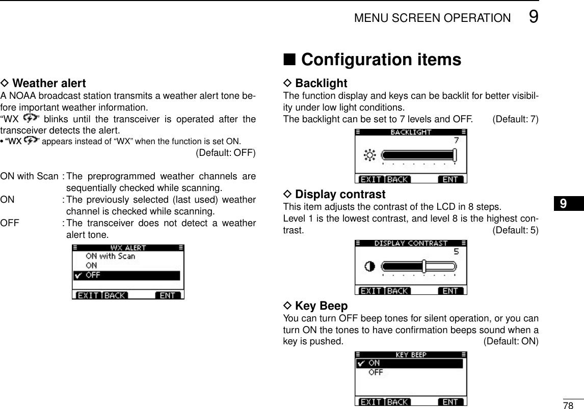
![New200175New2001MENU SCREEN OPERATION9 ■Menu screen operationThe Menu screen is used for programming infrequently changed values, function settings or sending DSC calls.In addition to this page, see pages 76 through 82 for details. DEntering the Menu screen and operationExample: Set the channel group to “INT.”Push [MENU]. q Rotate Dial or push [ w∫]/[√] to select the root item (Radio Setting), and then push [ENT]. •If[∫] or [√] is continuously held down, the items are sequentially highlighted. Rotate Dial or push [ e∫]/[√] to se-lect “CHAN Group,” and then push [ENT]. Rotate Dial or push [ r∫]/[√] to select “USA,” and then push [ENT] to set it. •“✔” is displayed next to “INT.” tPush [EXIT] to exit the Menu screen. •Push [CLEAR] or [BACK] to return tothe previous screen.[ENT][Y]/[Z][CLEAR][EXIT] [ENT][BACK] Dial[MENU]Menu lists](https://usermanual.wiki/ICOM-orporated/333800/User-Guide-1676007-Page-84.png)
![799MENU SCREEN OPERATIONNew2001Key Assignment DDesired functions can be assigned to Dial and the softkeys. When the “KEY ASSIGNMENT” screen is displayed, rotate qDial or push [∫]/[√] to select “Dial” or “Softkeys,” and then push [ENT]. Rotate Dial or push [ w∫]/[√] to select the desired position, and then push [ENT]. •Toreturntothedefault,select“Setdefault”andpush[ENT].For “Dial” assignment For “Softkeys” assignment Rotate Dial or push [ e∫]/[√] to select the option, and then push [ENT] to set it. •“✔” is displayed next to the selected option.For “Dial” assignment For “Softkeys” assignment* * [CHAN] appears instead of [CH/WX] only for Chinese version transceiver. Push [EXIT] to exit the Menu screen. r •Push[CLEAR]or[BACK]toreturntothepreviousscreen.• Dial assignmentThe audio volume (VOL), squelch (SQL), channel selection (CHAN) and LCD backlight level (Backlight) functions can be assigned to any one of 4 positions. After the functions have been assigned, pushing Dial sequentially selects the desired function, and then rotating Dial adjusts the level or selects a value or number.To quickly select the function assigned to only the 1st se-quential position ([ / Push × 1 ]), simply rotate Dial to dis-play the function screen. Then, rotate Dial again to adjust the level or select a value or number. To select the 2nd, 3rd or 4th functions, push Dial the required number of times. VOL (Volume) (p. 15) Push Dial one or more times, or rotate Dial to display the volume adjustment screen, and then rotate Dial to adjust the volume level. SQL (Squelch) (p. 15) Push Dial one or more times, or rotate Dial to display the squelch adjustment screen, and then rotate Dial to adjust the squelch level.](https://usermanual.wiki/ICOM-orporated/333800/User-Guide-1676007-Page-88.png)
![809MENU SCREEN OPERATIONNew200112345678910111213141516 CHAN (Channel) Push Dial one or more times, or rotate Dial to display the operating channel selection screen, and then rotate Dial to select the operating channel. Backlight (p. 16) Push Dial one or more times, or rotate Dial to display the backlight adjustment screen, and then rotate Dial to adjust the brightness of the LCD and key backlight level. Not Used No function NOTE: If you assign “Not Used,” assign it in [Push × 4 ]. If it is assigned to other position, the required num-ber of times for pushing Dial will be changed.Example:When “Not Used” is assigned to [Push × 2 ], and “SQL” is assigned to [Push × 3 ], pushing Dial two time displays the squelch adjustment screen.• Softkeys assignmentThe desired function can be assigned as the softkey func-tion. The assigned function can be used when its key icon is displayed.See page 3 for details of the assignable key functions.UTC Offset DSet the offset time between the UTC (Universal Time Coordi-nated) and your local time to between –14:00 and +14:00 (in 1 minute steps). (Default: 00:00)Noise Cancel DSet the Noise Cancel function for both receive and transmit. qWhen the “NOISE CANCEL” screen is displayed, rotate Dial or push [∫]/[√] to select “RX” or “TX,” and then push [ENT]. Rotate Dial or push [ w∫]/[√] to select the option, and then push [ENT] to set it. •“✔” is displayed next to the selected option. Push [EXIT] to exit the Menu screen. e •Push[CLEAR]or[BACK]toreturntothepreviousscreen.](https://usermanual.wiki/ICOM-orporated/333800/User-Guide-1676007-Page-89.png)
![819MENU SCREEN OPERATIONNew2001• RXTurn the receive Noise Cancel function ON or OFF. OFF : Turns OFF the function. (Default)1 : The Noise Cancel function reduces random noise com-ponents in the received signal to approximately one half.2 : The Noise Cancel function reduces random noise com-ponents in the received signal to approximately one third.3 : The Noise Cancel function reduces random noise com-ponents in the received signal to approximately one tenth.• TXTurn the transmit Noise Cancel function ON or OFF. OFF : Turns OFF the function. (Default)ON : The Noise Cancel function reduces random noise com-ponents in the transmitted signal to one tenth. Inactivity Timer DSet the inactivity timer to between 1 and 10 minutes (in 1 min-ute steps) or OFF for the “Not DSC Related” and “DSC Re-lated” item, and set to between 1 and 15 minutes (in 1 minute steps) or OFF for the “DSC Related” item. The count down alarm sounds 10 seconds before the Inactive timer returns the current screen to the normal operating screen. When the “INACTIVITY TIMER” screen is displayed, rotate qDial or push [∫]/[√] to select “Not DSC Related” or “DSC Related,” and then push [ENT]. Rotate Dial or push [ w∫]/[√] to select the option, and then push [ENT] to set it. •“✔” is displayed next to the selected option.Push [EXIT] to exit the Menu screen. e •Push[CLEAR]or[BACK]toreturntothepreviousscreen.](https://usermanual.wiki/ICOM-orporated/333800/User-Guide-1676007-Page-90.png)
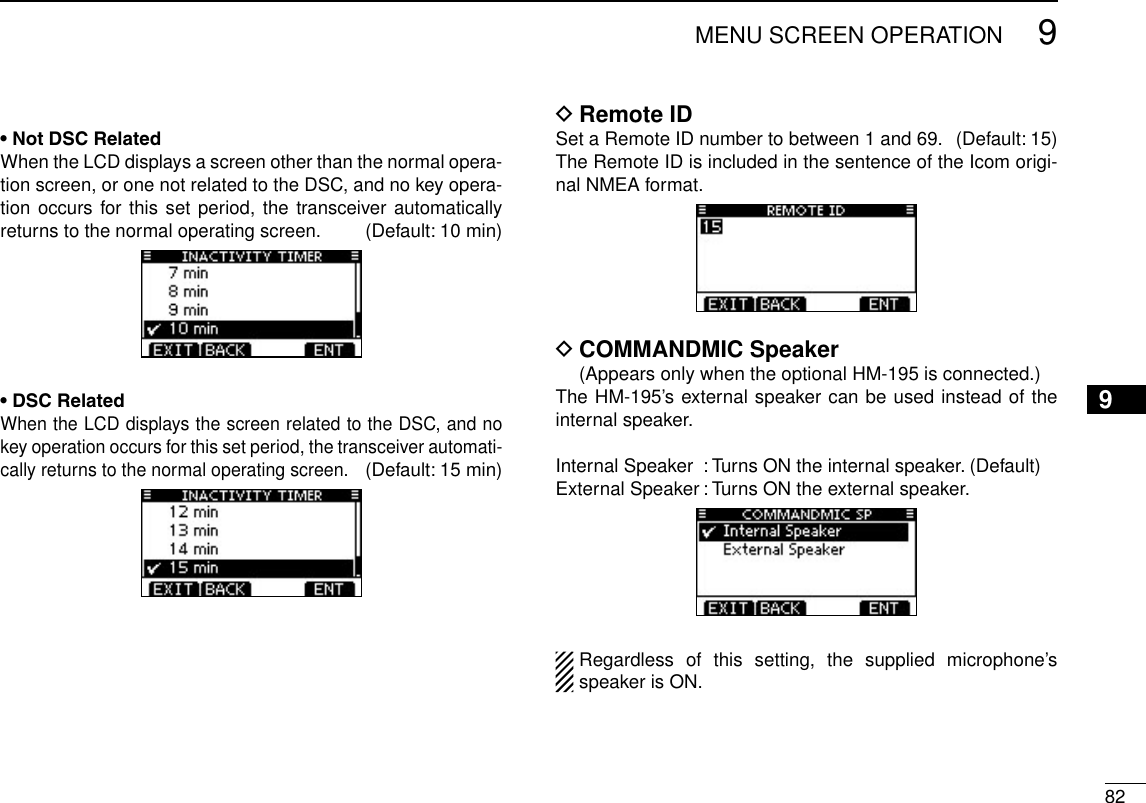
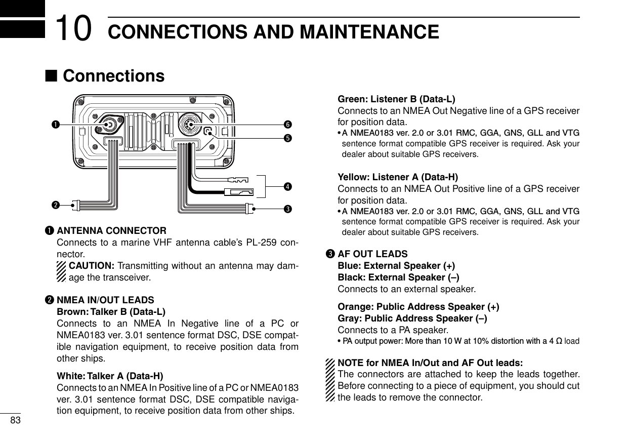
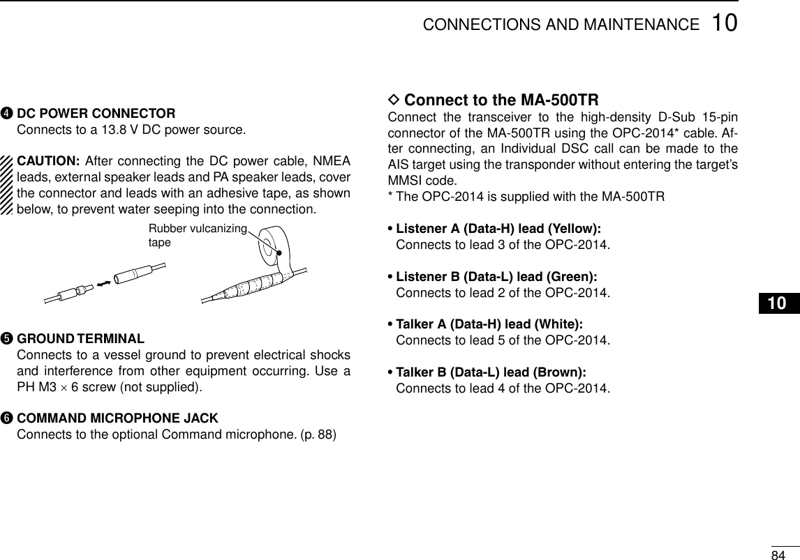
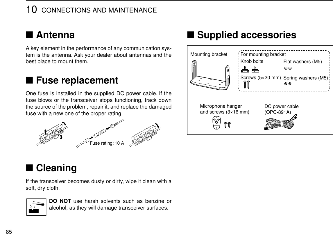
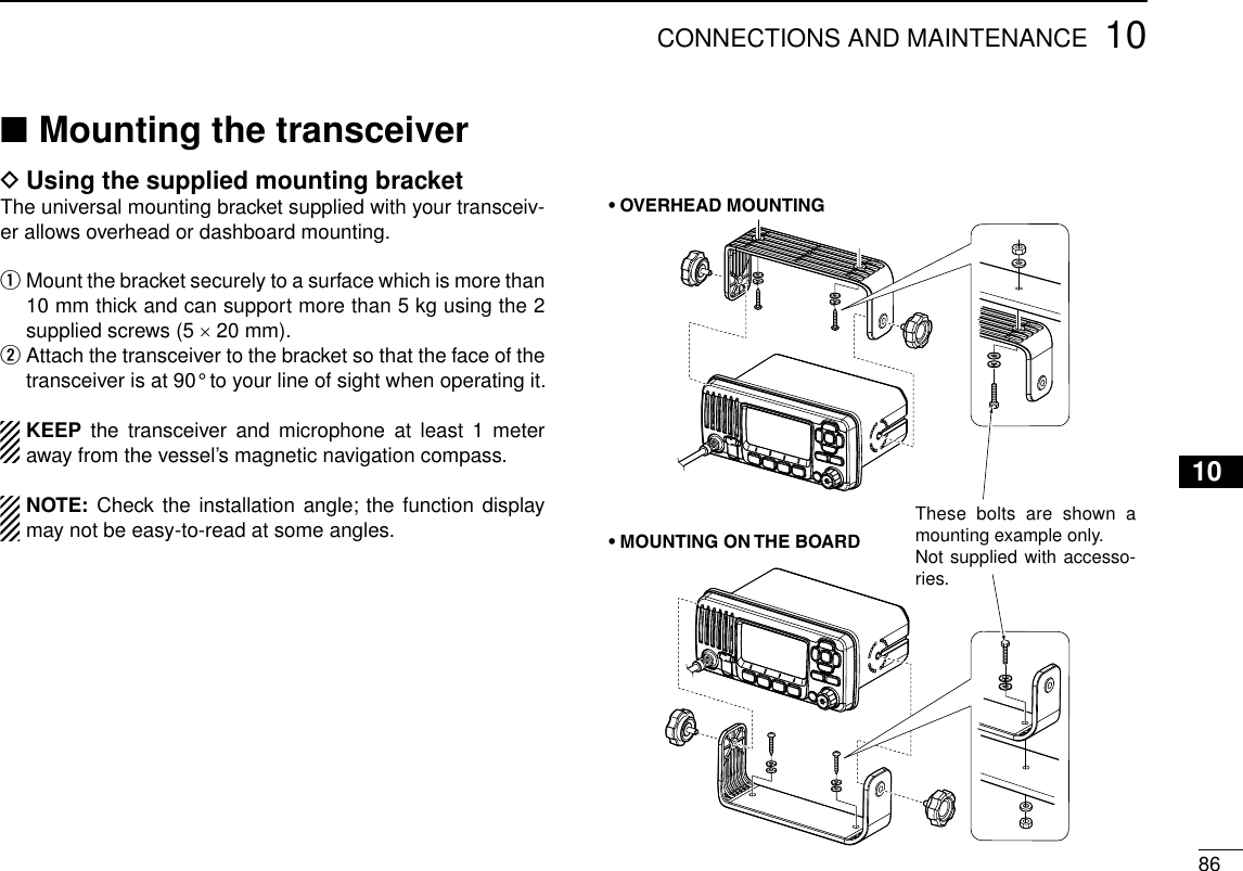
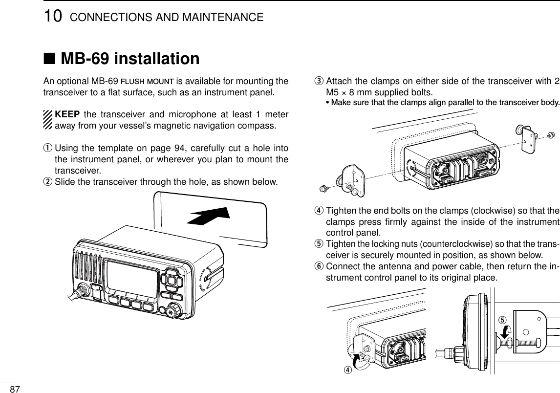
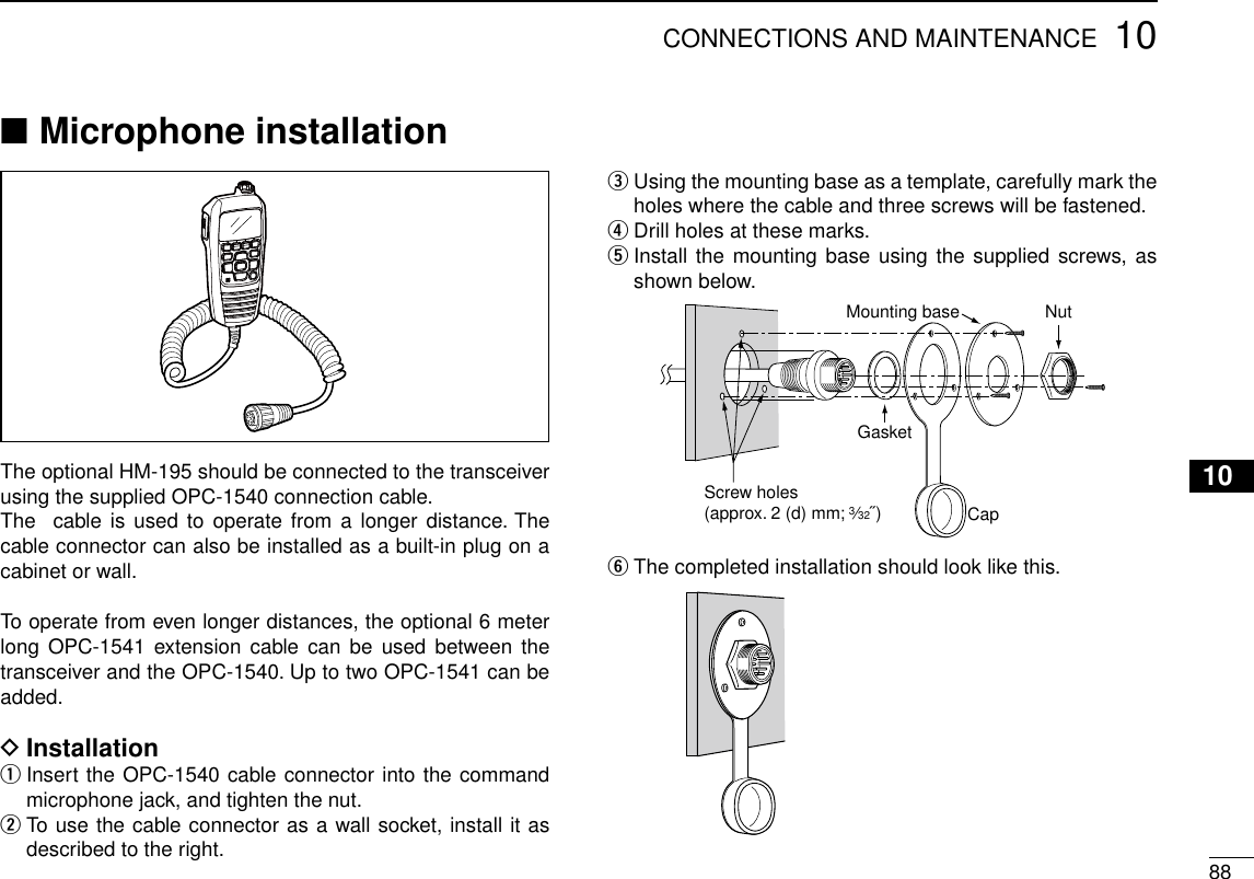
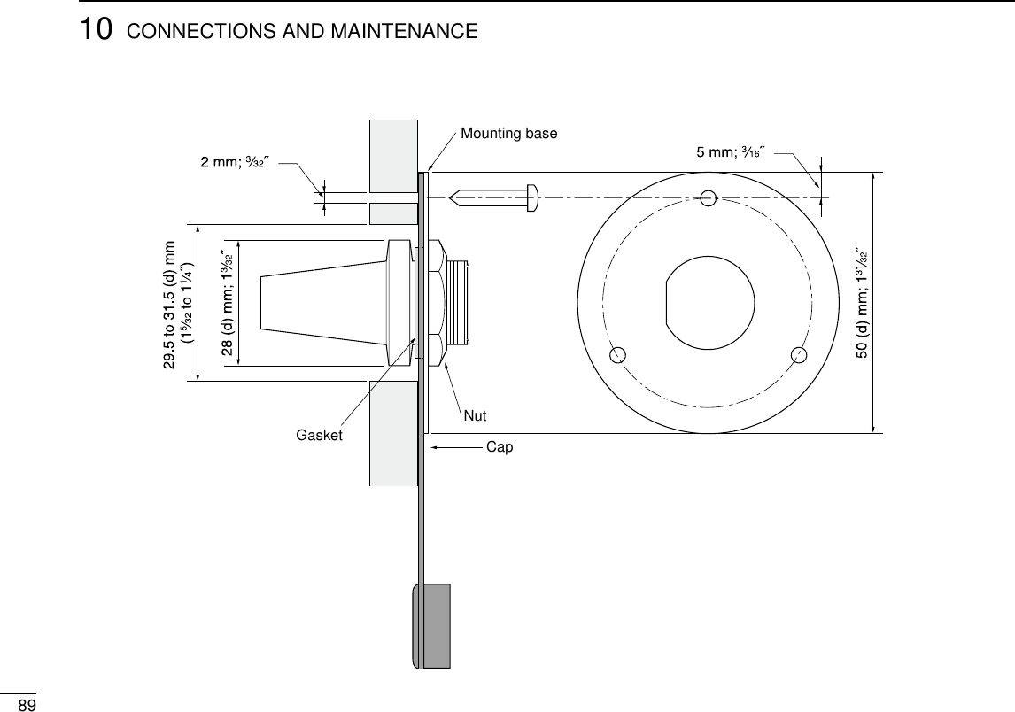
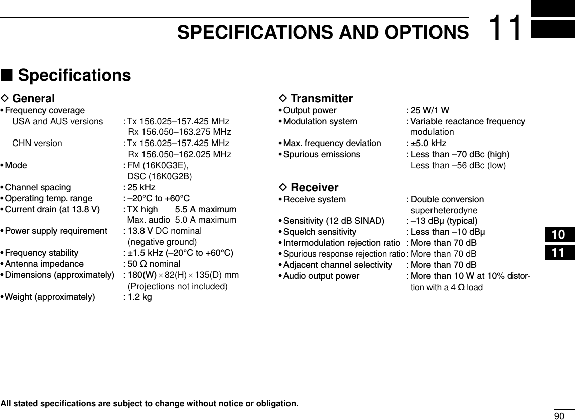
![New20019111 SPECIFICATIONS AND OPTIONSNew2001Dimensions D82 (3.23) 119.9 (4.72)164.1 (6.46)25.3(1) 109.7 (4.32)61.4 (2.42)Unit: mm (inch)180 (7.09)Options ■•MB-69 f l u s h m o u n t k i t To mount the transceiver to a panel.•HM-195 c o m m a n d m i c IV™ External microphone-type controller. Provides optional in-tercom operation. 6 m (20 ft) microphone cable and mount-ing base included. Black and white colors are available.•HM-196 h a n d m i c r o p h o n e Equipped with [Y]/[Z] (channel up/down,) [HI/LO] and [PTT] keys, a speaker and microphone.•OPC-1541 m i c r o p h o n e e x t e n s i o n c a b l e 6 m (20 feet) microphone extension cable for optional HM-195 c o m m a n d m i c IV™. Up to two OPC-1541 can be con-nected. Usable length is 18 m (60 ft) maximum.•MA-500TR c l a s s b a i s t r a n s p o n d e r To transmit individual DSC calls to a selected AIS targets.Approved Icom optional equipment is designed for optimal perfor-mance when used with an Icom transceiver.Icom is not responsible for the destruction or damage to an Icom transceiver in the event the Icom transceiver is used with equipment that is not manufactured or approved by Icom.](https://usermanual.wiki/ICOM-orporated/333800/User-Guide-1676007-Page-100.png)
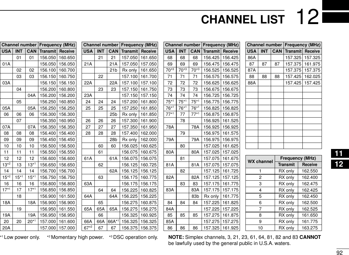
![93New2001TROUBLESHOOTING13PROBLEM POSSIBLE CAUSE SOLUTION REF.The transceiver does not turn ON.•Badconnectiontothepowersupply. •Checktheconnectiontothetransceiverandpower supply. p. 83Little or no sound comes from the speaker.•Squelchlevelissettoohigh.•Volumelevelissettoolow.•Speakerhasbeenexposedtowater.•Setthesquelchtothethresholdpoint.•Setthevolumetoasuitablelevel.•RemovethewaterwiththeAquaQuakefunc-tion.p. 15p. 15p. 16Transmitting is impossi-ble, or high power can-not be selected.•Some channels are programmed for lowpower or receive only by regulations.•Theoutputpowerissettolow.•Changechannels.•Push[HI/LO]toselecthighpower.pp. 9, 10, 11p. 11Scan does not start. •TAGchannelsarenotprogrammed. •SetthedesiredchannelsasTAGchannels. p. 18No beep sounds. •BeeptonesareturnedOFF. •TurnthebeeptonesONintheCONFIGURA-TION menu. p. 78Distress calls cannot be transmitted.•MMSI (DSC self ID) code is not pro-grammed.•ProgramtheMMSI(DSCselfID)code. p. 8](https://usermanual.wiki/ICOM-orporated/333800/User-Guide-1676007-Page-102.png)